WO2017191812A1 - Method for modifying carbon nanotube sheet, modified carbon nanotube sheet, method for manufacturing adhesive sheet, and adhesive sheet - Google Patents
Method for modifying carbon nanotube sheet, modified carbon nanotube sheet, method for manufacturing adhesive sheet, and adhesive sheet Download PDFInfo
- Publication number
- WO2017191812A1 WO2017191812A1 PCT/JP2017/016904 JP2017016904W WO2017191812A1 WO 2017191812 A1 WO2017191812 A1 WO 2017191812A1 JP 2017016904 W JP2017016904 W JP 2017016904W WO 2017191812 A1 WO2017191812 A1 WO 2017191812A1
- Authority
- WO
- WIPO (PCT)
- Prior art keywords
- carbon nanotube
- nanotube sheet
- sheet
- pressure
- sensitive adhesive
- Prior art date
Links
Images


Classifications
-
- C—CHEMISTRY; METALLURGY
- C09—DYES; PAINTS; POLISHES; NATURAL RESINS; ADHESIVES; COMPOSITIONS NOT OTHERWISE PROVIDED FOR; APPLICATIONS OF MATERIALS NOT OTHERWISE PROVIDED FOR
- C09J—ADHESIVES; NON-MECHANICAL ASPECTS OF ADHESIVE PROCESSES IN GENERAL; ADHESIVE PROCESSES NOT PROVIDED FOR ELSEWHERE; USE OF MATERIALS AS ADHESIVES
- C09J7/00—Adhesives in the form of films or foils
- C09J7/30—Adhesives in the form of films or foils characterised by the adhesive composition
-
- C—CHEMISTRY; METALLURGY
- C09—DYES; PAINTS; POLISHES; NATURAL RESINS; ADHESIVES; COMPOSITIONS NOT OTHERWISE PROVIDED FOR; APPLICATIONS OF MATERIALS NOT OTHERWISE PROVIDED FOR
- C09J—ADHESIVES; NON-MECHANICAL ASPECTS OF ADHESIVE PROCESSES IN GENERAL; ADHESIVE PROCESSES NOT PROVIDED FOR ELSEWHERE; USE OF MATERIALS AS ADHESIVES
- C09J7/00—Adhesives in the form of films or foils
- C09J7/20—Adhesives in the form of films or foils characterised by their carriers
- C09J7/29—Laminated material
-
- C—CHEMISTRY; METALLURGY
- C01—INORGANIC CHEMISTRY
- C01B—NON-METALLIC ELEMENTS; COMPOUNDS THEREOF; METALLOIDS OR COMPOUNDS THEREOF NOT COVERED BY SUBCLASS C01C
- C01B32/00—Carbon; Compounds thereof
- C01B32/15—Nano-sized carbon materials
- C01B32/158—Carbon nanotubes
- C01B32/16—Preparation
-
- C—CHEMISTRY; METALLURGY
- C01—INORGANIC CHEMISTRY
- C01B—NON-METALLIC ELEMENTS; COMPOUNDS THEREOF; METALLOIDS OR COMPOUNDS THEREOF NOT COVERED BY SUBCLASS C01C
- C01B32/00—Carbon; Compounds thereof
- C01B32/15—Nano-sized carbon materials
- C01B32/158—Carbon nanotubes
- C01B32/168—After-treatment
-
- C—CHEMISTRY; METALLURGY
- C09—DYES; PAINTS; POLISHES; NATURAL RESINS; ADHESIVES; COMPOSITIONS NOT OTHERWISE PROVIDED FOR; APPLICATIONS OF MATERIALS NOT OTHERWISE PROVIDED FOR
- C09J—ADHESIVES; NON-MECHANICAL ASPECTS OF ADHESIVE PROCESSES IN GENERAL; ADHESIVE PROCESSES NOT PROVIDED FOR ELSEWHERE; USE OF MATERIALS AS ADHESIVES
- C09J201/00—Adhesives based on unspecified macromolecular compounds
-
- C—CHEMISTRY; METALLURGY
- C09—DYES; PAINTS; POLISHES; NATURAL RESINS; ADHESIVES; COMPOSITIONS NOT OTHERWISE PROVIDED FOR; APPLICATIONS OF MATERIALS NOT OTHERWISE PROVIDED FOR
- C09J—ADHESIVES; NON-MECHANICAL ASPECTS OF ADHESIVE PROCESSES IN GENERAL; ADHESIVE PROCESSES NOT PROVIDED FOR ELSEWHERE; USE OF MATERIALS AS ADHESIVES
- C09J7/00—Adhesives in the form of films or foils
- C09J7/10—Adhesives in the form of films or foils without carriers
-
- C—CHEMISTRY; METALLURGY
- C09—DYES; PAINTS; POLISHES; NATURAL RESINS; ADHESIVES; COMPOSITIONS NOT OTHERWISE PROVIDED FOR; APPLICATIONS OF MATERIALS NOT OTHERWISE PROVIDED FOR
- C09J—ADHESIVES; NON-MECHANICAL ASPECTS OF ADHESIVE PROCESSES IN GENERAL; ADHESIVE PROCESSES NOT PROVIDED FOR ELSEWHERE; USE OF MATERIALS AS ADHESIVES
- C09J7/00—Adhesives in the form of films or foils
- C09J7/20—Adhesives in the form of films or foils characterised by their carriers
-
- C—CHEMISTRY; METALLURGY
- C09—DYES; PAINTS; POLISHES; NATURAL RESINS; ADHESIVES; COMPOSITIONS NOT OTHERWISE PROVIDED FOR; APPLICATIONS OF MATERIALS NOT OTHERWISE PROVIDED FOR
- C09J—ADHESIVES; NON-MECHANICAL ASPECTS OF ADHESIVE PROCESSES IN GENERAL; ADHESIVE PROCESSES NOT PROVIDED FOR ELSEWHERE; USE OF MATERIALS AS ADHESIVES
- C09J7/00—Adhesives in the form of films or foils
- C09J7/30—Adhesives in the form of films or foils characterised by the adhesive composition
- C09J7/38—Pressure-sensitive adhesives [PSA]
- C09J7/381—Pressure-sensitive adhesives [PSA] based on macromolecular compounds obtained by reactions involving only carbon-to-carbon unsaturated bonds
- C09J7/385—Acrylic polymers
-
- C—CHEMISTRY; METALLURGY
- C09—DYES; PAINTS; POLISHES; NATURAL RESINS; ADHESIVES; COMPOSITIONS NOT OTHERWISE PROVIDED FOR; APPLICATIONS OF MATERIALS NOT OTHERWISE PROVIDED FOR
- C09J—ADHESIVES; NON-MECHANICAL ASPECTS OF ADHESIVE PROCESSES IN GENERAL; ADHESIVE PROCESSES NOT PROVIDED FOR ELSEWHERE; USE OF MATERIALS AS ADHESIVES
- C09J9/00—Adhesives characterised by their physical nature or the effects produced, e.g. glue sticks
- C09J9/02—Electrically-conducting adhesives
-
- C—CHEMISTRY; METALLURGY
- C01—INORGANIC CHEMISTRY
- C01B—NON-METALLIC ELEMENTS; COMPOUNDS THEREOF; METALLOIDS OR COMPOUNDS THEREOF NOT COVERED BY SUBCLASS C01C
- C01B2202/00—Structure or properties of carbon nanotubes
- C01B2202/08—Aligned nanotubes
-
- C—CHEMISTRY; METALLURGY
- C01—INORGANIC CHEMISTRY
- C01P—INDEXING SCHEME RELATING TO STRUCTURAL AND PHYSICAL ASPECTS OF SOLID INORGANIC COMPOUNDS
- C01P2004/00—Particle morphology
- C01P2004/01—Particle morphology depicted by an image
- C01P2004/02—Particle morphology depicted by an image obtained by optical microscopy
-
- C—CHEMISTRY; METALLURGY
- C01—INORGANIC CHEMISTRY
- C01P—INDEXING SCHEME RELATING TO STRUCTURAL AND PHYSICAL ASPECTS OF SOLID INORGANIC COMPOUNDS
- C01P2006/00—Physical properties of inorganic compounds
- C01P2006/60—Optical properties, e.g. expressed in CIELAB-values
-
- C—CHEMISTRY; METALLURGY
- C08—ORGANIC MACROMOLECULAR COMPOUNDS; THEIR PREPARATION OR CHEMICAL WORKING-UP; COMPOSITIONS BASED THEREON
- C08K—Use of inorganic or non-macromolecular organic substances as compounding ingredients
- C08K3/00—Use of inorganic substances as compounding ingredients
- C08K3/02—Elements
- C08K3/04—Carbon
- C08K3/041—Carbon nanotubes
-
- C—CHEMISTRY; METALLURGY
- C09—DYES; PAINTS; POLISHES; NATURAL RESINS; ADHESIVES; COMPOSITIONS NOT OTHERWISE PROVIDED FOR; APPLICATIONS OF MATERIALS NOT OTHERWISE PROVIDED FOR
- C09J—ADHESIVES; NON-MECHANICAL ASPECTS OF ADHESIVE PROCESSES IN GENERAL; ADHESIVE PROCESSES NOT PROVIDED FOR ELSEWHERE; USE OF MATERIALS AS ADHESIVES
- C09J2301/00—Additional features of adhesives in the form of films or foils
- C09J2301/20—Additional features of adhesives in the form of films or foils characterized by the structural features of the adhesive itself
- C09J2301/206—Additional features of adhesives in the form of films or foils characterized by the structural features of the adhesive itself the adhesive layer comprising non-adhesive protrusions
-
- C—CHEMISTRY; METALLURGY
- C09—DYES; PAINTS; POLISHES; NATURAL RESINS; ADHESIVES; COMPOSITIONS NOT OTHERWISE PROVIDED FOR; APPLICATIONS OF MATERIALS NOT OTHERWISE PROVIDED FOR
- C09J—ADHESIVES; NON-MECHANICAL ASPECTS OF ADHESIVE PROCESSES IN GENERAL; ADHESIVE PROCESSES NOT PROVIDED FOR ELSEWHERE; USE OF MATERIALS AS ADHESIVES
- C09J2301/00—Additional features of adhesives in the form of films or foils
- C09J2301/30—Additional features of adhesives in the form of films or foils characterized by the chemical, physicochemical or physical properties of the adhesive or the carrier
- C09J2301/314—Additional features of adhesives in the form of films or foils characterized by the chemical, physicochemical or physical properties of the adhesive or the carrier the adhesive layer and/or the carrier being conductive
-
- C—CHEMISTRY; METALLURGY
- C09—DYES; PAINTS; POLISHES; NATURAL RESINS; ADHESIVES; COMPOSITIONS NOT OTHERWISE PROVIDED FOR; APPLICATIONS OF MATERIALS NOT OTHERWISE PROVIDED FOR
- C09J—ADHESIVES; NON-MECHANICAL ASPECTS OF ADHESIVE PROCESSES IN GENERAL; ADHESIVE PROCESSES NOT PROVIDED FOR ELSEWHERE; USE OF MATERIALS AS ADHESIVES
- C09J2301/00—Additional features of adhesives in the form of films or foils
- C09J2301/40—Additional features of adhesives in the form of films or foils characterized by the presence of essential components
- C09J2301/408—Additional features of adhesives in the form of films or foils characterized by the presence of essential components additives as essential feature of the adhesive layer
-
- C—CHEMISTRY; METALLURGY
- C09—DYES; PAINTS; POLISHES; NATURAL RESINS; ADHESIVES; COMPOSITIONS NOT OTHERWISE PROVIDED FOR; APPLICATIONS OF MATERIALS NOT OTHERWISE PROVIDED FOR
- C09J—ADHESIVES; NON-MECHANICAL ASPECTS OF ADHESIVE PROCESSES IN GENERAL; ADHESIVE PROCESSES NOT PROVIDED FOR ELSEWHERE; USE OF MATERIALS AS ADHESIVES
- C09J2301/00—Additional features of adhesives in the form of films or foils
- C09J2301/40—Additional features of adhesives in the form of films or foils characterized by the presence of essential components
- C09J2301/41—Additional features of adhesives in the form of films or foils characterized by the presence of essential components additives as essential feature of the carrier layer
-
- C—CHEMISTRY; METALLURGY
- C09—DYES; PAINTS; POLISHES; NATURAL RESINS; ADHESIVES; COMPOSITIONS NOT OTHERWISE PROVIDED FOR; APPLICATIONS OF MATERIALS NOT OTHERWISE PROVIDED FOR
- C09J—ADHESIVES; NON-MECHANICAL ASPECTS OF ADHESIVE PROCESSES IN GENERAL; ADHESIVE PROCESSES NOT PROVIDED FOR ELSEWHERE; USE OF MATERIALS AS ADHESIVES
- C09J2400/00—Presence of inorganic and organic materials
- C09J2400/10—Presence of inorganic materials
- C09J2400/12—Ceramic
- C09J2400/123—Ceramic in the substrate
-
- C—CHEMISTRY; METALLURGY
- C09—DYES; PAINTS; POLISHES; NATURAL RESINS; ADHESIVES; COMPOSITIONS NOT OTHERWISE PROVIDED FOR; APPLICATIONS OF MATERIALS NOT OTHERWISE PROVIDED FOR
- C09J—ADHESIVES; NON-MECHANICAL ASPECTS OF ADHESIVE PROCESSES IN GENERAL; ADHESIVE PROCESSES NOT PROVIDED FOR ELSEWHERE; USE OF MATERIALS AS ADHESIVES
- C09J2433/00—Presence of (meth)acrylic polymer
Definitions
- the present invention relates to a method for modifying a carbon nanotube sheet, a modified carbon nanotube sheet, a method for producing an adhesive sheet, and an adhesive sheet.
- Patent Document 1 discloses a nanofiber sheet containing carbon nanotubes.
- a treatment such as exposing the carbon nanotube sheet to liquid vapor may be performed.
- the carbon nanotube sheet contracts in a direction (width direction) perpendicular to the fiber axis (alignment direction of the carbon nanotubes) in plan view.
- An object of the present invention is to provide a reforming method for preventing shrinkage in the width direction of a carbon nanotube sheet during processing such as exposure to liquid vapor. Another object of the present invention is to provide a modified carbon nanotube sheet obtained by the modification method. Another object of the present invention is to provide a method for producing an adhesive sheet using a modified carbon nanotube sheet obtained by the modification method. Another object of the present invention is to provide an adhesive sheet using the modified carbon nanotube sheet obtained by the modification method.
- a method for modifying a carbon nanotube sheet the step of placing one or a plurality of carbon nanotube sheets on a structure, and the carbon nanotube sheet on the structure being liquid at room temperature
- the carbon nanotube sheet has a structure in which a plurality of carbon nanotubes are preferentially aligned in one direction in the sheet surface, and the structure includes the carbon nanotube sheet.
- the placement section for placing the nanotube sheet has a non-contact portion that does not contact the carbon nanotube sheet and a contact portion that contacts the carbon nanotube sheet, the non-contact portion and the In the plan view of the boundary with the contact portion and the placement portion, the carbon nanotube is aligned in parallel with the alignment direction of the carbon nanotubes and directly across the non-contact portion.
- the non-contact part and the contact part is independently present in plural.
- both the non-contact portion and the contact portion are continuous.
- the non-contact portion of the structure has a fine hole.
- the structure preferably has a raised structure as the contact portion.
- the maximum distance L 1 is preferably less than 0mm super 10 mm.
- the structure includes a plurality of continuous contact portions and a plurality of continuous non-contact portions, and the plurality of continuous contact portions and the A plurality of continuous non-contact portions form a striped structure, and the striped structure intersects the alignment direction of the carbon nanotubes in the plan view and is opposed to adjacent continuous contact portions. It is also preferable that at each of the end portions that are in contact with each other, an arbitrary point on one end portion is provided so that the distance to the closest point on the other end portion is always less than 10 mm.
- a plurality of the carbon nanotube sheets are stacked on the structure, and then the plurality of carbon nanotube sheets on the structure are liquid at room temperature.
- An exposure step to the vapor or particles of the material may be performed.
- the modified carbon nanotube sheet preferably has a light transmittance of 70% or more.
- a modified carbon nanotube sheet obtained by the method for modifying a carbon nanotube sheet according to one aspect of the present invention, and the light beam of the modified carbon nanotube sheet.
- a modified carbon nanotube sheet having a transmittance of 70% or more is provided.
- a method for producing a pressure-sensitive adhesive sheet comprising a step of laminating a carbon nanotube sheet on a pressure-sensitive adhesive layer containing a pressure-sensitive adhesive.
- the modified carbon nanotube sheet obtained by the method for modifying a carbon nanotube sheet according to one aspect the surface opposite to the adhesive layer side surface of the modified carbon nanotube sheet is pasted to an adherend.
- a method for producing a pressure-sensitive adhesive sheet is provided, wherein the pressure-sensitive adhesive strength of the pressure-sensitive adhesive sheet measured is 8 N / 25 mm or more.
- the pressure-sensitive adhesive sheet includes a carbon nanotube sheet and a pressure-sensitive adhesive layer containing a pressure-sensitive adhesive.
- a modified carbon nanotube sheet obtained by the method for modifying a carbon nanotube sheet according to one aspect of the invention, wherein the surface of the modified carbon nanotube sheet opposite to the surface on the pressure-sensitive adhesive layer side is an adherend.
- a pressure-sensitive adhesive sheet is provided, wherein the pressure-sensitive adhesive sheet has an adhesive strength of 8 N / 25 mm or more as measured by being attached to a sheet.
- the present invention it is possible to provide a modification method for preventing shrinkage in the width direction of the carbon nanotube sheet during the treatment such as exposure to liquid vapor. Moreover, according to the present invention, it is possible to provide a modified carbon nanotube sheet obtained by the modification method. Moreover, according to this invention, the manufacturing method of the adhesive sheet using the modified carbon nanotube sheet obtained by the said modification method can be provided. Moreover, according to this invention, the adhesive sheet using the modified
- FIG. 3 is a sectional view taken along line III-III in FIG. 2. It is a microscope picture of the carbon nanotube sheet which gave the modification method of a first embodiment. It is a section schematic diagram of the adhesive sheet of a first embodiment. It is the schematic which shows an example of the structure which concerns on 2nd embodiment.
- FIG. 7 is a sectional view taken along line VII-VII in FIG. 6.
- This modification method includes a step of placing one or a plurality of carbon nanotube sheets on a structure (hereinafter, sometimes referred to as “placement step” for convenience), and the carbon nanotube sheet on the structure is liquid at room temperature. And a step of exposing to vapor or particles of the substance (hereinafter, also referred to as “exposure step” for convenience).
- placement step for convenience
- exposure step for convenience
- the carbon nanotube sheet according to the present embodiment has a structure in which a plurality of carbon nanotubes are preferentially aligned in one direction within the sheet surface.
- the “structure in which the carbon nanotubes are aligned in one direction in the sheet surface” refers to a state in which the carbon nanotubes are aligned in one direction in the sheet surface. However, they are aligned so as to be parallel to one direction in the sheet surface.
- the “preferentially aligned state” means that the aligned state is mainstream.
- the aligned state is mainstream, some of the carbon nanotubes are carbon The long axis of the nanotube may not be aligned so as to be parallel to one direction in the sheet surface.
- the carbon nanotube sheet is, for example, a carbon nanotube forest (a growth body in which a plurality of carbon nanotubes are grown on a substrate so as to be oriented in a direction perpendicular to the main surface of the substrate, and is called an “array”.
- the carbon nanotubes assembled by the intermolecular force are pulled out in a sheet state and pulled away from the substrate.
- a carbon nanotube sheet is placed on the structure. At this time, a single carbon nanotube sheet that is not stacked may be placed, or a sheet in which a plurality of carbon nanotube sheets are previously stacked may be placed.
- the structure according to the present modification method has a placement portion on which the carbon nanotube sheet is placed.
- the mounting portion of the structure includes a non-contact portion that does not contact the carbon nanotube sheet and a contact portion that contacts the carbon nanotube sheet.
- L 1 is the longest distance between the intersections in the non-contact portion between the boundary between the non-contact portion and the contact portion and the straight line parallel to the alignment direction of the carbon nanotubes and straddling the non-contact portion in the plan view of the placement portion.
- L 2 when L 1 is larger than L 2 , at least L 2 is preferably more than 10 ⁇ m and 5 mm or less, more preferably 50 ⁇ m or more and 2 mm or less, and 100 ⁇ m or more and 1.5 mm or less. Is more preferable.
- L 1 when L 1 is smaller than L 2 , at least L 1 is preferably more than 10 ⁇ m and 5 mm or less, more preferably 50 ⁇ m or more and 2 mm or less, and 100 ⁇ m or more and 1.5 mm or less. Is more preferable.
- L 1 and L 2 are preferably more than 10 ⁇ m and 5 mm or less, more preferably 50 ⁇ m or more and 2 mm or less, and 100 ⁇ m or more and 1.5 mm or less. More preferably.
- At least one of the non-contact part and the contact part exists independently.
- the shape of the non-contact part is not particularly limited, for example, square, rectangular, rectangular, circular, elliptical, honeycomb, comb-like
- the shape may be a straight line, a curved line, a wavy line (sinusoidal curve or the like), a polygonal mesh, or the like, or an irregular shape.
- the non-contact part may have a fine hole so that it may mention later.
- each of the independent contact parts is adjacent to (adjacent to) another contact part in the sheet surface in plan view of the placement part.
- the shortest distance is preferably more than 0 mm and less than 10 mm.
- the carbon nanotube sheet a plurality of carbon nanotubes that are preferentially aligned in one direction in the sheet surface are bundled around the direction in the exposure step described later. In this direction, due to the existence of a plurality of individual contact portions that are close to each other, when the carbon nanotubes are bundled, the distance between both ends of the sheet fixed by the contact portions is shortened.
- the plurality of independent contact portions each have a shortest distance of 10 ⁇ m or more and 5 mm or less, more preferably 50 ⁇ m or more and 2 mm or less, in plan view of the placement portion, More preferably, it is 100 ⁇ m or more and 1.5 mm or less.
- the shape of the contact portion is not particularly limited, and may be, for example, a square, a rectangle, a rectangle, a circle, an ellipse, a curve, a wavy line (such as a sine wave curve), a polygon, or the like, or an irregular shape. May be.
- bundling means that the carbon nanotubes constituting the carbon nanotube sheet are in a state in which a plurality of adjacent carbon nanotubes are bundled (structure assembled in a fibrous form). .
- bundling process the process of bundling the carbon nanotubes included in the carbon nanotube sheet is referred to as “bundling process”.
- longest distance L 2 is, with respect to the alignment direction of the carbon nanotubes in the carbon nanotube sheet, straight line intersecting at an angle of 60 ⁇ 90 ° in a plan view of the mounting portion And more than 0 mm and less than 10 mm. More preferably substantially orthogonal (cross at an angle of 80 ⁇ 90 °) to a straight line (see Figure 1 for the case of 90 °) is the longest distance L 2 has, the longest distance L 2 is 0mm It is preferably less than 10 mm.
- Structure according to the present modification process is more preferable maximum distance L 1 is less than 0mm super 10 mm. That is, in the structure, the longest distance between adjacent contact portions (the most spaced distance between the ends of both contact portions) in the alignment direction of the carbon nanotubes is preferably more than 0 mm and less than 10 mm. That is, for a contact portion that is arbitrarily drawn on the surface of the structure and exists on a straight line parallel to the alignment direction of the carbon nanotubes, the length of the straight line segment between adjacent contact portions is more than 0 mm and less than 10 mm. There is preferably (see FIG. 1).
- a plurality of carbon nanotubes that are preferentially aligned in one direction in the sheet surface are bundled around the direction as an axis in an exposure step described later.
- the distance between adjacent contact portions is smaller than 10 mm
- the distance between both ends of the sheet fixed by the contact portions when the plurality of carbon nanotubes are bundled is shortened.
- the number of carbon nanotubes to be bundled becomes moderate, and a uniform distribution of carbon nanotubes is easily maintained.
- the longest distance between adjacent contact portions in the alignment direction of the carbon nanotubes is more preferably more than 10 ⁇ m and not more than 5 mm, further preferably not less than 50 ⁇ m and not more than 2 mm, and more preferably not less than 100 ⁇ m and not more than 1.5 mm. More preferred.
- the carbon nanotube sheet corresponding to the contact portion is not subjected to bundling of carbon nanotubes. Therefore, in order to increase the proportion of the area of the bundling-treated portion in the entire carbon nanotube sheet, it is necessary to relatively reduce the area of the contact portion in the structure.
- the distance between adjacent non-contact portions is preferably more than 0 mm and less than 5 mm. That is, for a non-contact portion existing on a straight line parallel to the alignment direction of the carbon nanotubes arbitrarily drawn on the surface of the structure (surface having the mounting portion), the straight line between the adjacent non-contact portions.
- the length of the minute is preferably more than 0 mm and less than 5 mm.
- the distance between adjacent non-contact portions is more preferably more than 10 ⁇ m and 2 mm or less, further preferably 50 ⁇ m or more and 1 mm or less, and further preferably 100 ⁇ m or more and 500 ⁇ m or less.
- “existing on a straight line parallel to the alignment direction of the carbon nanotubes arbitrarily drawn on the surface of the structure” means that as long as the effect of the invention is obtained, only on a part of the surface of the structure, It exists on the straight line parallel to the alignment direction of the carbon nanotube arbitrarily drawn.
- none of the maximum distance L 1 and the maximum distance L 2 is preferably less than 0mm super 10 mm.
- the structure according to the present modification method for example, a structure in which the non-contact part has fine holes is used.
- micropore refers to a hole having an opening diameter (minimum diameter of the hole) of less than 10 mm.
- a structure having a non-contact portion having a fine hole can also be adopted in a second embodiment to be described later. By adopting such a structure in this embodiment, the non-contact portion and the contact portion are used. It is possible to easily obtain a structure in which at least one of the plurality is independently present. From the viewpoint of preventing shrinkage in the width direction of the carbon nanotube sheet, in this embodiment, the opening diameter of the micropores is preferably 5 mm or less, more preferably 2 mm or less, and 1.5 mm or less. Is more preferable.
- the lower limit of the opening diameter of the micropores is not particularly limited, and may be appropriately designed in consideration of the light transmittance and adhesive strength of the carbon nanotube sheet, but is usually 1 ⁇ m or more, preferably 5 ⁇ m or more, and preferably 10 ⁇ m or more. Is more preferable.
- the shape of the opening of the fine hole is not particularly limited. The fine holes preferably have a maximum diameter of more than 0 mm and less than 10 mm.
- the structure according to the present modification method may be a structure having a plurality of micropores and continuous contact portions, or may be a structure having a plurality of micropores and a plurality of independent contact portions.
- the “continuous contact portion” means that the contact portion is not closed by the non-contact portion in the plan view of the placement portion.
- continuous non-contact portion means that the non-contact portion is not closed by the contact portion in a plan view of the placement portion.
- Examples of the structure according to the present embodiment include a mesh shape, a net shape, a punching shape, an embossed shape, a lattice shape, or a combination of these. More specifically, for example, as a structure having a plurality of fine holes and continuous contact portions, sponge, macroporous material (for example, pumice, macroporous ceramic, etc.), honeycomb porous structure, and punching processing are performed. Metal foil and the like. In these structures, the non-contact portions having fine holes are independent. Further, for example, as a structure having a plurality of fine holes and a plurality of independent contact portions, a metal mesh, a planar sphere-filling structure, and the like can be given. In these structures, non-contact portions having fine holes are continuous. In addition, you may form the structure which has a micropore by well-known means, such as 3D printer.
- FIG. 2 is a schematic view showing another example of the structure according to the first embodiment, in which a part of the carbon nanotube sheet 5A supported by the mesh-like structure 1A is broken.
- the mesh-like structure 1A has a plurality of fine holes 2A in a lattice pattern.
- L 1 is the minimum diameter of the micropores 2A (opening diameter of fine holes 2A).
- the mesh-like structure 1A has a raised structure in which threads constituting the mesh are patterned, and the raised structure on the side on which the carbon nanotube sheet 5A is placed has a contact portion 3A with the carbon nanotube sheet 5A. (See FIG. 3).
- the carbon nanotube sheet 5A placed on the mesh-like structure 1A is exposed to vapor or particles (aerosol) of a liquid substance at room temperature.
- the carbon nanotubes of the carbon nanotube sheet 5A can be bundled by the exposure process.
- room temperature means a temperature of 25 ° C.
- Examples of substances that are liquid at room temperature according to the present embodiment include water and organic solvents.
- Examples of the organic solvent include alcohols, ketones, and esters.
- Examples of alcohols include ethanol, methanol, and isopropyl alcohol.
- Examples of ketones include acetone and methyl ethyl ketone.
- Examples of the esters include ethyl acetate.
- the carbon nanotube sheet 5A placed on the mesh-like structure 1A As a method for exposing the carbon nanotube sheet 5A placed on the mesh-like structure 1A to vapor or particles (aerosol) of a liquid substance at room temperature, for example, the carbon nanotube sheet 5A on the mesh-like structure 1A is applied to the carbon nanotube sheet 5A. After spraying a liquid substance at room temperature and generating an aerosol of the liquid substance at room temperature using an ultrasonic humidifier or the like, the carbon nanotube sheet 5A is meshed with the mesh structure 1A in the generated aerosol. And the method of exposing the whole.
- vapor or particles (aerosol) of a liquid substance at room temperature for example, the carbon nanotube sheet 5A on the mesh-like structure 1A is applied to the carbon nanotube sheet 5A. After spraying a liquid substance at room temperature and generating an aerosol of the liquid substance at room temperature using an ultrasonic humidifier or the like, the carbon nanotube sheet 5A is meshed with the mesh structure 1A in the
- the particle size of the substance that is liquid at normal temperature (the particles attached to the carbon nanotube sheet 5A are randomly selected from the viewpoint of facilitating entry of the particles into the carbon nanotube sheet 5A.
- the average of the major axis of the particles, extracted at 10 points and observed with an optical microscope is preferably 5 nm to 200 ⁇ m, more preferably 7.5 nm to 100 ⁇ m, and more preferably 10 nm to 50 ⁇ m. More preferably, it is as follows.
- the average diameter of the structure in which carbon nanotubes are gathered in a fibrous form is preferably 1 ⁇ m or more and 300 ⁇ m or less, more preferably 3 ⁇ m or more. It is 150 micrometers or less, More preferably, they are 5 micrometers or more and 50 micrometers or less.
- the average diameter of a structure in which carbon nanotubes are gathered into a fiber shape refers to the average diameter of the outer circumference of the structure.
- the contact portion 3A which is a portion where the yarn constituting the mesh in the mesh-like structure 1A forms a patterned raised structure, and the carbon nanotube sheet 5A come into contact with each other.
- the portion of the carbon nanotube sheet 5A that is in contact with 3A is not bundled, and is not in contact with the portion (the portion corresponding to the bottom of the fine hole 2A of the mesh-like structure 1A and the ridge structure of the yarn constituting the mesh)
- the carbon nanotubes of the carbon nanotube sheet 5A at a location corresponding to (b) are bundled (see FIG. 4).
- the bundling process is performed on the carbon nanotube sheet 5A on the mesh-like structure 1A having a plurality of fine holes (non-contact portions having a predetermined opening diameter) 2A in the plan view of the mounting portion 4A. By doing so, contraction in the width direction of the carbon nanotube sheet 5A is prevented.
- the present modification method as a result of a bundle of a plurality of adjacent carbon nanotubes, voids are generated in the carbon nanotube sheet 5A, and as a result, the light transmittance of the carbon nanotube sheet 5A is improved. Moreover, effects such as reduction in sheet resistance can be obtained.
- the carbon nanotube sheet is disposed on a support structure that does not have a non-contact portion and subjected to a treatment such as exposure to liquid vapor, the entire surface of the carbon nanotube sheet on the support structure side comes into contact with the support structure.
- the carbon nanotube sheet only moves to the support structure side (thickness direction of the carbon nanotube sheet), and the carbon nanotubes do not collect in a fibrous form. Therefore, effects such as improvement in light transmittance and reduction in surface resistance cannot be obtained.
- the non-bundled portion is formed on the carbon nanotube sheet in accordance with the pattern of the non-contact portion having the fine holes 2A of the mesh-like structure 1A. Can do.
- Modified carbon nanotube sheet According to this modification method, for example, a carbon nanotube sheet with modified light transmittance, surface resistance, and the like is obtained.
- the modified carbon nanotube sheet preferably has a light transmittance of 70% or more. If the light transmittance of the carbon nanotube sheet is 70% or more, for example, it is suitably used for a passenger car window where visibility is required, a mirror where contrast clarity is required, and the like.
- the light transmittance of the carbon nanotube sheet can be improved, for example, by increasing the number of voids in the carbon nanotube sheet. In order to increase the voids in the carbon nanotube sheet, for example, the area of the non-contact portion may be increased by increasing the opening diameter of the micropores in the structure.
- the light transmittance of the modified carbon nanotube sheet is preferably 70% or more and 100% or less, and more preferably 80% or more and 99.9% or less.
- the light transmittance can be measured using, for example, an optical transmittance measuring device using a visible-ultraviolet light source and a spectroscope.
- FIG. 5 shows a schematic cross-sectional view of the pressure-sensitive adhesive sheet 10 of the present embodiment.
- the adhesive sheet 10 which concerns on this embodiment has the carbon nanotube sheet
- the pressure-sensitive adhesive sheet 10 according to this embodiment includes a first surface 11a of the carbon nanotube sheet 11 (hereinafter, also referred to as “first sheet surface 11a”) and a first surface 12a of the pressure-sensitive adhesive layer 12 (hereinafter, referred to as “first surface 11a”). “May be referred to as“ first adhesive surface 12a ”).
- the carbon nanotube sheet 11 is a carbon nanotube sheet subjected to bundling treatment obtained by the carbon nanotube sheet modification method of the present embodiment described above. Therefore, the light transmittance of the carbon nanotube sheet 11 can be improved.
- the thickness t 11 (see FIG. 5) of the carbon nanotube sheet 11 is appropriately determined according to the application of the pressure-sensitive adhesive sheet 10.
- the carbon nanotube sheet 11 is interposed between the adherend and the pressure-sensitive adhesive layer 12 to increase the light transmittance of the pressure-sensitive adhesive sheet 10 when the pressure-sensitive adhesive sheet 10 is attached to the adherend and the light transmittance of the pressure-sensitive adhesive sheet 10 is increased.
- the thickness t 11 of the carbon nanotube sheet 11 is preferably 0.01 ⁇ m or more and 100 ⁇ m or less, and more preferably 0.05 ⁇ m or more and 75 ⁇ m or less.
- the adhesive which comprises the adhesive layer 12 is not specifically limited.
- the pressure-sensitive adhesive include acrylic pressure-sensitive adhesives, urethane-based pressure-sensitive adhesives, rubber-based pressure-sensitive adhesives, polyester-based pressure-sensitive adhesives, silicone-based pressure-sensitive adhesives, and polyvinyl ether-based pressure-sensitive adhesives.
- the pressure-sensitive adhesive constituting the pressure-sensitive adhesive layer 12 is preferably at least one selected from the group consisting of an acrylic pressure-sensitive adhesive, a urethane pressure-sensitive adhesive, and a rubber pressure-sensitive adhesive, and is preferably an acrylic pressure-sensitive adhesive. More preferred.
- the acrylic pressure-sensitive adhesive contains an acrylic polymer.
- the acrylic polymer includes, for example, a structural unit derived from an alkyl (meth) acrylate having a linear alkyl group or a branched alkyl group, a structural unit derived from a (meth) acrylate having a cyclic structure, and the like.
- (meth) acrylate is used as a term indicating both “acrylate” and “methacrylate”, and the same applies to other similar terms.
- the structural unit of the acrylic polymer is an alkyl (meth) acrylate (a1 ′) having an alkyl group having 1 to 20 carbon atoms (hereinafter also referred to as “monomer component (a1 ′)”). ),
- the above-mentioned acrylic polymer can be a copolymer containing at least one of the structural units (a1) and (a2) and including two or more selected from the structural units (a1) to (a3).
- the form of copolymerization is not particularly limited, and any of a block copolymer, a random copolymer, and a graft copolymer may be used.
- the number of carbon atoms of the alkyl group contained in the monomer component (a1 ′) is preferably 1 to 18, more preferably 2 to 14, and still more preferably 4 to 12, from the viewpoint of improving adhesive properties.
- the number of carbon atoms of the alkyl group of the monomer component (a1 ′) is within such a range, the interaction between the main chains of the acrylic polymer is inhibited, and the influence of crystallization of the side chain is small. Therefore, the glass transition temperature of the acrylic polymer is maintained low, and the adhesiveness of the adhesive is easily improved.
- second sheet surface 11b (hereinafter sometimes referred to as “second sheet surface 11b”)) is attached to the adherend. It becomes easy to adjust the adhesive force of the measured adhesive sheet 10 to the range mentioned later.
- Examples of the monomer component (a1 ′) include methyl (meth) acrylate, ethyl (meth) acrylate, propyl (meth) acrylate, n-butyl (meth) acrylate, isobutyl (meth) acrylate, 2-ethylhexyl (meth) ) Acrylate, n-octyl acrylate, isooctyl (meth) acrylate, decyl (meth) acrylate, lauryl (meth) acrylate, tridecyl (meth) acrylate, and stearyl (meth) acrylate.
- n-butyl (meth) acrylate, isobutyl (meth) acrylate, 2-ethylhexyl (meth) acrylate, n-octyl acrylate, isooctyl (meth) acrylate, decyl (meth) Acrylate and lauryl (meth) acrylate are preferred, and n-butyl (meth) acrylate and 2-ethylhexyl (meth) acrylate are more preferred.
- the acrylic polymer is an acrylic copolymer containing at least the structural unit (a1) and further including any one or more of the structural units (a2) and (a3)
- the structural unit (a1) The content is preferably 50% by mass or more and 99.5% by mass or less, more preferably 55% by mass or more and 99% by mass or less, and still more preferably, with respect to all the structural units (100% by mass) of the acrylic copolymer. Is 60% by mass or more and 97% by mass or less, and more preferably 65% by mass or more and 95% by mass or less.
- Examples of the monomer component (a2 ′) include hydroxy group-containing monomers, carboxy group-containing monomers, epoxy group-containing monomers, amino group-containing monomers, cyano group-containing monomers, keto group-containing monomers, and alkoxysilyl group-containing monomers. Is mentioned. Among these monomer components (a2 ′), a hydroxy group-containing monomer and a carboxy group-containing monomer are preferable.
- hydroxy group-containing monomer examples include 2-hydroxyethyl (meth) acrylate, 2-hydroxypropyl (meth) acrylate, 2-hydroxybutyl (meth) acrylate, 3-hydroxybutyl (meth) acrylate, and 4-hydroxybutyl.
- (Meth) acrylate and the like can be mentioned, and 2-hydroxyethyl (meth) acrylate is preferred.
- carboxy group-containing monomer examples include (meth) acrylic acid, maleic acid, fumaric acid, and itaconic acid, with (meth) acrylic acid being preferred.
- Examples of the epoxy group-containing monomer include glycidyl (meth) acrylate.
- Examples of the amino group-containing monomer include diaminoethyl (meth) acrylate.
- Examples of the cyano group-containing monomer include acrylonitrile.
- the structural unit (a2) is preferably 0.1% by mass or more and 50% by mass or less, more preferably 0.5% by mass or more and 40% by mass or less, with respect to all the structural units (100% by mass) of the acrylic copolymer. More preferably, they are 1.0 mass% or more and 30 mass% or less, More preferably, they are 1.5 mass% or more and 20 mass% or less.
- Examples of the monomer component (a3 ′) include (meth) acrylate having a cyclic structure, vinyl acetate, and styrene.
- Examples of the (meth) acrylate having a cyclic structure include cyclohexyl (meth) acrylate, benzyl (meth) acrylate, isobornyl (meth) acrylate, dicyclopentanyl (meth) acrylate, dicyclopentenyl (meth) acrylate, and dicyclo Examples thereof include pentenyloxyethyl (meth) acrylate, imide (meth) acrylate, and acryloylmorpholine.
- the acrylic polymer is an acrylic copolymer containing at least the structural unit (a1) or (a2) and further including the structural unit (a3)
- the content of the structural unit (a3) Preferably it is larger than 0 mass% and 40 mass% or less, More preferably, it is larger than 0 mass% and 30 mass% or less, More preferably, it is 0 mass% with respect to all the structural units (100 mass%) of a system copolymer. Is more than 25% by mass, more preferably more than 0% by mass and not more than 20% by mass.
- the above-mentioned monomer component (a1 ′) may be used alone or in combination of two or more, and the above-mentioned monomer component (a2 ′) is used alone or in combination of two or more.
- the monomer component (a3 ′) described above may be used alone or in combination of two or more.
- the weight average molecular weight of the acrylic polymer is preferably 50,000 or more and 2,500,000 or less, and more preferably 100,000 or more and 1,500,000 or less. Generally, as the weight average molecular weight of the acrylic polymer is lower, the pressure-sensitive adhesive is softened and the pressure-sensitive adhesive tends to be improved. When adjusting the adhesive strength of the pressure-sensitive adhesive sheet 10 measured by applying the second sheet surface 11b to the adherend to a range described later, the weight average molecular weight of the acrylic polymer is adjusted within such a range. The adhesive force can be easily controlled.
- the acrylic polymer may be cross-linked.
- a crosslinking agent a well-known epoxy type crosslinking agent, an isocyanate type crosslinking agent, an aziridine type crosslinking agent, a metal chelate type crosslinking agent, etc. can be used, for example.
- a functional group derived from the monomer component (a2 ′) can be used as a crosslinking point that reacts with the crosslinking agent. Since the physical properties of the acrylic polymer may not be easily controlled only with the structural unit (a2), in this case, the acrylic polymer is divided into the structural unit (a2), at least the structural unit (a1), and It is preferable to use an acrylic copolymer containing any of (a3).
- the addition amount of the crosslinking agent is preferably 0.01 parts by mass or more and 15 parts by mass or less, and more preferably 0.05 parts by mass or more and 10 parts by mass or less with respect to 100 parts by mass of the acrylic copolymer. .
- the amount of the crosslinking agent is adjusted within such a range, Force can be controlled easily.
- the pressure-sensitive adhesive layer forming composition constituting the pressure-sensitive adhesive layer 12 may contain other components as long as the effects of the present invention are not impaired.
- examples of other components that can be included in the composition for forming an adhesive layer include organic solvents, flame retardants, tackifiers, ultraviolet absorbers, antioxidants, antiseptics, antifungal agents, plasticizers, and antifoaming agents. , And wettability adjusting agents.
- the tackifier is preferably 1 part by mass or more and 300 parts by mass or less with respect to 100 parts by mass of the acrylic adhesive.
- the thickness t 12 (see FIG. 5) of the pressure-sensitive adhesive layer 12 is appropriately determined according to the application of the pressure-sensitive adhesive sheet 10.
- the thickness t 12 of the carbon nanotube sheet 11 first seat surface 11a which is formed on the adhesive layer 12 of, 3 [mu] m or more 150 ⁇ m or less is adjusted preferably in the range of 5 ⁇ m or 100 ⁇ m or less.
- t 12 is preferably 1 ⁇ m or more and 20 ⁇ m or less, and more preferably 2 ⁇ m or more and 9 ⁇ m or less from the viewpoint of reducing the thickness of the entire pressure-sensitive adhesive sheet 10 and obtaining sufficient adhesiveness.
- the pressure-sensitive adhesive sheet 10 covers the second sheet surface 11b from the viewpoint of sufficient fixation to the adherend and from the viewpoint of removal performance when removing an object such as a contaminant due to the adhesiveness of the pressure-sensitive adhesive sheet.
- the adhesive strength measured by sticking to the body is 8 N / 25 mm or more. More preferably, it is 9N / 25mm or more, More preferably, it is 9.5N / 25mm or more.
- the upper limit of the adhesive force measured by attaching the second sheet surface 11b of the carbon nanotube sheet 11 to the adherend is not particularly limited, but is usually about 35 N / 25 mm or less.
- the adhesive force in this specification is the value measured about 30 minutes after sticking by a 180 degree peeling method at a pulling speed of 300 mm / min and a sheet width of 25 mm based on JIS Z0237: 2000. It is.
- the adhesive strength of the adhesive sheet 10 measured by attaching the second sheet surface 11b to the adherend is usually measured as it is when the adhesive sheet 10 does not have a support. It is affected by the elongation of the layer 12. Therefore, the adhesive force in this case is the surface opposite to the surface adjacent to the carbon nanotube sheet 11 of the pressure-sensitive adhesive layer 12 (second surface 12b (hereinafter also referred to as “second adhesive surface 12b”)).
- second adhesive surface 12b (hereinafter also referred to as “second adhesive surface 12b”)).
- a sample obtained by laminating a polyethylene terephthalate film having a thickness of 25 ⁇ m as a support is measured.
- a plurality of adjacent carbon nanotubes are bundled, resulting in voids in the carbon nanotube sheet.
- the manufacturing method of the adhesive sheet 10 of this embodiment includes the process of laminating
- Other steps are not particularly limited.
- the adhesive sheet 10 is manufactured through the following processes. First, a carbon nanotube forest is formed on a substrate such as a silicon wafer by a known method. Next, a carbon nanotube sheet is produced by twisting the end of the formed forest and pulling it out with tweezers or the like. And the carbon nanotube sheet 11 is obtained by performing the modification
- an adhesive is applied on the release sheet to form a coating film.
- the coating film is dried to produce the pressure-sensitive adhesive layer 12.
- the first sheet surface 11a of the carbon nanotube sheet 11 is bonded (laminated) to the first pressure-sensitive adhesive surface 12a of the produced pressure-sensitive adhesive layer 12. Then, if a peeling sheet is peeled off, the adhesive sheet 10 will be obtained.
- the pressure-sensitive adhesive sheet 10 according to the present embodiment has good handleability of the carbon nanotube sheet and can be easily applied to various uses.
- the second embodiment is different from the first embodiment in that the structure according to the carbon nanotube sheet modification method uses a structure having a contact part with a continuous mounting part and a continuous non-contact part. Is different. Since the second embodiment is the same as the first embodiment in other points, the description is omitted or simplified.
- the structure includes a plurality of continuous contact portions (hereinafter also referred to as “a plurality of support portions”) and a plurality of continuous non-contact portions.
- the form which these form the striped structure is mentioned.
- the plurality of support portions (for example, a striped structure) intersect with the alignment direction of the carbon nanotubes in the carbon nanotube sheet in a plan view of the mounting portion, and preferably intersect at an angle of 60 to 90 °.
- the lines constituting the stripes may be straight lines, for example, wavy lines, curved lines, bent lines, or the like.
- the adjacent end portions of the adjacent continuous contact portions are arranged at the other end portion at any one end portion.
- the distance to the closest point is always 5 mm or less, more preferably 2 mm or less, and even more preferably 1.5 mm or less.
- the lower limit value of the longest distance between each of the plurality of support portions is not particularly limited, and may be appropriately designed in consideration of the light transmittance and adhesive strength of the carbon nanotube sheet, but is usually 10 ⁇ m or more and 50 ⁇ m. The above is preferable, and 100 ⁇ m or more is more preferable.
- the maximum distance L 1 is preferably less than 0mm super 10 mm.
- the plurality of support portions and the continuous non-contact portions form a striped structure, one end of each of the adjacent continuous contact portions facing each other
- the distance from the arbitrary point of the part to the closest point of the other end is always less than 10 mm, and the plurality of support parts are arranged in the plane of the mounting part with respect to the alignment direction of the carbon nanotubes in the carbon nanotube sheet. This is easily realized by being substantially orthogonal in view.
- FIG. 6 is a schematic view showing an example of a structure according to the second embodiment, in which a part of the carbon nanotube sheet 5B supported by the structure 1B having a plurality of continuous contact portions 2B is broken and illustrated.
- the structure 1B according to the reforming method of the present embodiment includes a plurality of continuous contact portions 2B and a continuous non-contact portion 3B.
- the plurality of contact portions 2B are orthogonal to the alignment direction of the carbon nanotubes in the carbon nanotube sheet 5B in a plan view of the placement portion 4B (see FIG. 7).
- Distance L 1 between adjacent contact portions 2B is as described above.
- the carbon nanotube sheet 5B placed on the structure 1B is in contact with the contact portion 2B (see FIG. 7).
- the structure on which the carbon nanotube sheet is placed may be a structure having a raised structure as a plurality of independent contact portions and a continuous non-contact portion.
- a structure in which a plurality of needle-like structures, a columnar structure, a raised structure having a gentle slope, and the like are erected on a base.
- the tip portion of the raised structure or the like that is a contact portion with the carbon nanotube sheet is flat or curved.
- the shape of the needle or column include a columnar shape and a conical shape.
- the structure on which the carbon nanotube sheet is placed may be a film in which irregularities are formed by the addition of sandblast or filler, an embossed film, and the like.
- structures having a plurality of fine holes and a plurality of independent contact portions such as a metal mesh and a planar sphere-filling structure, also have a raised structure.
- the structure on which the carbon nanotubes are mounted is an embossed film in addition to the structure having the fine holes as described above and the structure having the raised structure, and a continuous flat unprocessed portion is formed.
- a structure having a contact part and having a plurality of independent depressions as non-contact parts is also included in the first embodiment.
- an exposure step was performed.
- a plurality of carbon nanotube sheets may be laminated, and then the exposure step may be performed.
- the effect of preventing shrinkage in the width direction of the carbon nanotube sheets can be further obtained.
- a treatment is performed by performing a placing process and an exposure process on one carbon nanotube sheet, and a stacked body in which a plurality of carbon nanotube sheets subjected to the processing are stacked. Further, a placing step and an exposing step may be performed. Also in this case, the carbon nanotube sheet subjected to the treatment may be laminated on the structure in the placing step.
- an exposure step is performed, and another carbon nanotube sheet is stacked on the carbon nanotube sheet.
- An exposure process may be performed, and this procedure may be repeated to sequentially perform the exposure process on the laminate.
- the pressure-sensitive adhesive layer 12 may be curable.
- the pressure-sensitive adhesive layer 12 is cured, impact resistance is improved, and deformation of the pressure-sensitive adhesive layer 12 due to impact can be prevented.
- the pressure-sensitive adhesive sheet 10 preferably has a support.
- a support may be laminated on the second pressure-sensitive adhesive surface 12 b, and a subject such as a contaminant due to the viewpoint for sufficient fixation of the pressure-sensitive adhesive sheet 10 to the adherend and the pressure-sensitive adhesive property of the pressure-sensitive adhesive sheet 10. From the viewpoint of removal performance when removing an object, it is preferable that the adhesive strength measured by attaching the second sheet surface 11b to the adherend is within the above range.
- a support may be laminated on the second sheet surface 11 b of the carbon nanotube sheet 11.
- the support can be bonded to the carbon nanotube sheet 11 by the adhesiveness developed on the second sheet surface 11b due to the influence of the adhesive exposed in the voids of the carbon nanotube sheet 11 subjected to the bundling treatment.
- Examples of the support include paper, a resin film, a cured product of a curable resin, a metal foil, and a glass film.
- Examples of the resin film include polyester, polycarbonate, polyimide, polyolefin, polyurethane, and acrylic resin films.
- the surface of the support opposite to the surface adjacent to the pressure-sensitive adhesive layer 12 or the carbon nanotube sheet 11 is subjected to a hard coat treatment using an ultraviolet curable resin or the like in order to enhance protection. Also good.
- the pressure-sensitive adhesive sheet when the pressure-sensitive adhesive sheet is provided with a release material on either the second pressure-sensitive adhesive surface 12b of the pressure-sensitive adhesive layer 12 or the second sheet surface 11b of the carbon nanotube sheet 11, the pressure-sensitive adhesive sheet has the above-described support on the other side. It may be.
- the release material is not particularly limited.
- the release material preferably includes a release substrate and a release agent layer formed by applying a release agent on the release substrate.
- the release material may be provided with a release agent layer only on one side of the release substrate, or may be provided with a release agent layer on both sides of the release substrate.
- the release substrate include a paper substrate, a laminated paper obtained by laminating a thermoplastic resin such as polyethylene on the paper substrate, and a plastic film.
- the paper substrate include glassine paper, coated paper, and cast coated paper.
- plastic film examples include polyester films such as polyethylene terephthalate, polybutylene terephthalate, and polyethylene naphthalate, and polyolefin films such as polypropylene and polyethylene.
- release agent examples include olefin-based resins, rubber-based elastomers (for example, butadiene-based resins and isoprene-based resins), long-chain alkyl-based resins, alkyd-based resins, fluorine-based resins, and silicone-based resins. .
- the thickness of the release material is not particularly limited. Usually, it is 20 ⁇ m or more and 200 ⁇ m or less, and preferably 25 ⁇ m or more and 150 ⁇ m or less.
- the thickness of the release agent layer is not particularly limited.
- the thickness of the release agent layer is preferably 0.01 ⁇ m or more and 2.0 ⁇ m or less, and 0.03 ⁇ m or more and 1.0 ⁇ m or less. Is more preferable.
- the thickness of the plastic film is preferably 3 ⁇ m or more and 50 ⁇ m or less, and more preferably 5 ⁇ m or more and 40 ⁇ m or less.
- the pressure-sensitive adhesive sheet 10 includes a pressure-sensitive adhesive layer 12 on the second sheet surface 11 b of the carbon nanotube sheet 11 in addition to the pressure-sensitive adhesive layer 12 (hereinafter also referred to as “first pressure-sensitive adhesive layer” for convenience). (Hereinafter, sometimes referred to as “second pressure-sensitive adhesive layer” for convenience).
- first pressure-sensitive adhesive layer for convenience
- second pressure-sensitive adhesive layer for convenience
- the pressure-sensitive adhesive contained in the first pressure-sensitive adhesive layer and the pressure-sensitive adhesive contained in the second pressure-sensitive adhesive layer may be the same, similar or completely different.
- a support may be provided on the surface of either one of the first pressure-sensitive adhesive layer and the second pressure-sensitive adhesive layer opposite to the surface adjacent to the carbon nanotube sheet 11.
- the thickness t 21 of the first pressure-sensitive adhesive layer and the thickness t 22 of the second pressure-sensitive adhesive layer are each independently preferably 3 ⁇ m or more and 150 ⁇ m or less, and more preferably 5 ⁇ m or more and 100 ⁇ m or less. .
- the total value (total thickness of the pressure-sensitive adhesive layer) of the first and the thickness t 21 of the pressure-sensitive adhesive layer a second thickness of the pressure-sensitive adhesive layer t 22 is preferably 10 ⁇ m or more 300 ⁇ m or less, 20 [mu] m or more 200 ⁇ m or less It is more preferable that A release material may be further laminated on each of the first pressure-sensitive adhesive layer and the second pressure-sensitive adhesive layer.
- Shrinkage rate (Wi ⁇ Wt) / Wi Wi: Width of the carbon nanotube sheet before bundling treatment (average length in a direction perpendicular to the alignment direction of the carbon nanotubes in the carbon nanotube sheet in plan view)
- Wt Width of the carbon nanotube sheet after bundling treatment (the length of the most contracted portion in the direction perpendicular to the alignment direction of the carbon nanotubes in the carbon nanotube sheet in plan view)
- Example 1 [Modification of carbon nanotube sheet] (1) Preparation of carbon nanotube forest and production of carbon nanotube sheet On a silicon wafer by catalytic chemical vapor deposition using a thermal CVD apparatus equipped with three furnaces using argon gas as a carrier gas and acetylene as a carbon source A carbon nanotube forest was formed. The height of the carbon nanotube forest was 300 ⁇ m. A carbon nanotube sheet with a width of 50 mm was produced by twisting the end of the formed carbon nanotube forest and pulling it out with tweezers.
- Example 2 A carbon nanotube sheet was produced in the same manner as the production of the carbon nanotube sheet in Example 1. This new carbon nanotube sheet is further superposed on the carbon nanotube sheet before modification on the metal mesh, that is, the carbon nanotube sheet is reformed after the number of layers is increased to two by laminating one layer of the carbon nanotube sheet.
- a pressure-sensitive adhesive sheet according to Example 2 was produced in the same manner as Example 1 except that the above was performed.
- Example 3 A carbon nanotube sheet was produced in the same manner as the production of the carbon nanotube sheet in Example 1. This new carbon nanotube sheet is further superposed on the carbon nanotube sheet before modification on the metal mesh, that is, the carbon nanotube sheet is reformed after the number of layers is increased to three by stacking two layers of carbon nanotube sheets.
- a pressure-sensitive adhesive sheet according to Example 3 was produced in the same manner as Example 1 except that the above was performed.
- Reference Example 1 A pressure-sensitive adhesive sheet according to Reference Example 1 was produced in the same manner as in Example 1 except that the carbon nanotube sheet was not bonded to the surface of the pressure-sensitive adhesive layer.
- Comparative Example 1 Instead of attaching the carbon nanotube sheet to the metal mesh, it was attached to a release film (SP-PET 381031 manufactured by Lintec Corporation) placed on a flat plate. A pressure-sensitive adhesive sheet according to Comparative Example 1 was produced in the same manner as in Example 1 except that the carbon nanotube sheet on the release film was pressure-bonded to the pressure-sensitive adhesive layer without performing a bundling process. .
- Example 2 A carbon nanotube sheet was produced in the same manner as the production of the carbon nanotube sheet in Example 1. This new carbon nanotube sheet was further superposed on the carbon nanotube sheet on the release film, that is, compared with Comparative Example 1 except that the number of layers was two by laminating one carbon nanotube sheet. A pressure-sensitive adhesive sheet according to Example 2 was produced.
- Example 3 A carbon nanotube sheet was produced in the same manner as the production of the carbon nanotube sheet in Example 1. This new carbon nanotube sheet was further superposed on the carbon nanotube sheet on the release film, that is, the same as in Comparative Example 1, except that the number of layers was three by stacking two layers of carbon nanotube sheets. A pressure-sensitive adhesive sheet according to Example 3 was produced.
- a carbon nanotube sheet was produced in the same manner as the production of the carbon nanotube sheet in Example 1. This new carbon nanotube sheet is further superposed on the carbon nanotube sheet before modification held by two parallel rods, that is, after the number of layers is made two by laminating one carbon nanotube sheet.
- a carbon nanotube sheet subjected to the bundling process according to Comparative Example 5 was obtained in the same manner as in Comparative Example 4 except that the bundling process was performed. Since the carbon nanotube sheet contracted by the bundling treatment, an adhesive sheet was not manufactured.
- a carbon nanotube sheet was produced in the same manner as the production of the carbon nanotube sheet in Example 1. This new carbon nanotube sheet is further superimposed on the carbon nanotube sheet before modification, which is locked to two parallel rods, that is, after the number of layers is made three by stacking two layers of carbon nanotube sheets.
- a carbon nanotube sheet subjected to the bundling process according to Comparative Example 6 was obtained in the same manner as in Comparative Example 4 except that the bundling process was performed. Since the carbon nanotube sheet contracted by the bundling treatment, an adhesive sheet was not manufactured.
- the present invention can be used when modifying a carbon nanotube sheet, for example, improving the light transmittance of the carbon nanotube sheet or reducing the resistance.
- the pressure-sensitive adhesive sheet of the present invention using the carbon nanotube sheet obtained by the present modification method can be suitably used as a heater or the like due to the excellent electrical conductivity of the carbon nanotube sheet.
Abstract
Description
例えば、特許文献1には、カーボンナノチューブを含むナノファイバーシートが開示されている。 Conventionally, a sheet using carbon nanotubes is known. Such a carbon nanotube sheet has characteristics not found in other materials, such as conductivity, heat generation, and in-plane anisotropy.
For example,
しかしながら、フリースタンディング(自立)の状態でこのような処理を行った場合、カーボンナノチューブシートが、平面視において繊維軸(カーボンナノチューブの整列方向)と直交する方向(幅方向)に収縮するという問題があった。 By the way, in order to modify the carbon nanotube sheet according to the application, for example, a treatment such as exposing the carbon nanotube sheet to liquid vapor may be performed.
However, when such treatment is performed in a free standing state, the carbon nanotube sheet contracts in a direction (width direction) perpendicular to the fiber axis (alignment direction of the carbon nanotubes) in plan view. there were.
[改質方法]
以下、本実施形態のカーボンナノチューブシートの改質方法(以下、「本改質方法」ということもある。)を説明する。 [First embodiment]
[Modification method]
Hereinafter, a method for modifying the carbon nanotube sheet of the present embodiment (hereinafter, also referred to as “the present modification method”) will be described.
以下、まず本実施形態に係るカーボンナノチューブシートについて説明し、その後、本改質方法の各工程について説明する。 This modification method includes a step of placing one or a plurality of carbon nanotube sheets on a structure (hereinafter, sometimes referred to as “placement step” for convenience), and the carbon nanotube sheet on the structure is liquid at room temperature. And a step of exposing to vapor or particles of the substance (hereinafter, also referred to as “exposure step” for convenience).
Hereinafter, the carbon nanotube sheet according to the present embodiment will be described first, and then each step of the modification method will be described.
本実施形態に係るカーボンナノチューブシートは、複数のカーボンナノチューブが、シート面内の一方向に優先的に整列した構造を有する。 (Carbon nanotube sheet)
The carbon nanotube sheet according to the present embodiment has a structure in which a plurality of carbon nanotubes are preferentially aligned in one direction within the sheet surface.
載置工程では、構造体上に、カーボンナノチューブシートを載置する。この時、積層されていない単一のカーボンナノチューブシートを載置してもよいし、複数のカーボンナノチューブシートが予め積層されたシートを載置してもよい。 (Installation process)
In the placing step, a carbon nanotube sheet is placed on the structure. At this time, a single carbon nanotube sheet that is not stacked may be placed, or a sheet in which a plurality of carbon nanotube sheets are previously stacked may be placed.
構造体の載置部は、カーボンナノチューブシートとは接触しない非接触部およびカーボンナノチューブシートと接触する接触部を有する。非接触部と接触部との境界と、載置部の平面視において、カーボンナノチューブの整列方向に平行し、かつ非接触部を跨ぐ直線との、非接触部における交点間の最長距離をL1とし、非接触部と前記接触部との境界と、載置部の平面視において、カーボンナノチューブの整列方向に交差し、かつ非接触部を跨ぐ直線との、非接触部における交点間の最長距離をL2としたとき、L1がL2よりも大きい場合、少なくともL2は0mm超10mm未満である。L1がL2よりも小さい場合、少なくともL1は0mm超10mm未満である。L1とL2が等しい場合、L1およびL2は0mm超10mm未満である。 The structure according to the present modification method has a placement portion on which the carbon nanotube sheet is placed.
The mounting portion of the structure includes a non-contact portion that does not contact the carbon nanotube sheet and a contact portion that contacts the carbon nanotube sheet. L 1 is the longest distance between the intersections in the non-contact portion between the boundary between the non-contact portion and the contact portion and the straight line parallel to the alignment direction of the carbon nanotubes and straddling the non-contact portion in the plan view of the placement portion. And the longest distance between the intersections in the non-contact portion between the boundary between the non-contact portion and the contact portion and the straight line crossing the alignment direction of the carbon nanotubes and straddling the non-contact portion in the plan view of the mounting portion when was the L 2, if L 1 is greater than L 2, at least L 2 is less than 0mm super 10 mm. If L 1 is smaller than L 2, at least L 1 is less than 0mm super 10 mm. When L 1 and L 2 are equal, L 1 and L 2 are more than 0 mm and less than 10 mm.
なお、以下、カーボンナノチューブシートが有するカーボンナノチューブをバンドリングする処理を「バンドリング処理」という。 Here, in the present specification, “bundling” means that the carbon nanotubes constituting the carbon nanotube sheet are in a state in which a plurality of adjacent carbon nanotubes are bundled (structure assembled in a fibrous form). .
Hereinafter, the process of bundling the carbon nanotubes included in the carbon nanotube sheet is referred to as “bundling process”.
なお、ここでいう「構造体表面において任意に引かれた、カーボンナノチューブの整列方向と平行な直線上に存在する」とは、発明の効果が得られる限り、構造体表面の一部のみにおいて、任意に引かれた、カーボンナノチューブの整列方向と平行な直線上に存在することを含む。 Further, as will be described later, in the exposure process, the carbon nanotube sheet corresponding to the contact portion is not subjected to bundling of carbon nanotubes. Therefore, in order to increase the proportion of the area of the bundling-treated portion in the entire carbon nanotube sheet, it is necessary to relatively reduce the area of the contact portion in the structure. From such a viewpoint, in the alignment direction of the carbon nanotubes, the distance between adjacent non-contact portions is preferably more than 0 mm and less than 5 mm. That is, for a non-contact portion existing on a straight line parallel to the alignment direction of the carbon nanotubes arbitrarily drawn on the surface of the structure (surface having the mounting portion), the straight line between the adjacent non-contact portions. The length of the minute is preferably more than 0 mm and less than 5 mm. In the alignment direction of the carbon nanotubes, the distance between adjacent non-contact portions is more preferably more than 10 μm and 2 mm or less, further preferably 50 μm or more and 1 mm or less, and further preferably 100 μm or more and 500 μm or less. .
As used herein, “existing on a straight line parallel to the alignment direction of the carbon nanotubes arbitrarily drawn on the surface of the structure” means that as long as the effect of the invention is obtained, only on a part of the surface of the structure, It exists on the straight line parallel to the alignment direction of the carbon nanotube arbitrarily drawn.
微細孔の開口部の形状は、特に限定されない。
微細孔は、最大径が0mm超10mm未満であることが好ましい。 Here, in this specification, “micropore” refers to a hole having an opening diameter (minimum diameter of the hole) of less than 10 mm. A structure having a non-contact portion having a fine hole can also be adopted in a second embodiment to be described later. By adopting such a structure in this embodiment, the non-contact portion and the contact portion are used. It is possible to easily obtain a structure in which at least one of the plurality is independently present. From the viewpoint of preventing shrinkage in the width direction of the carbon nanotube sheet, in this embodiment, the opening diameter of the micropores is preferably 5 mm or less, more preferably 2 mm or less, and 1.5 mm or less. Is more preferable. The lower limit of the opening diameter of the micropores is not particularly limited, and may be appropriately designed in consideration of the light transmittance and adhesive strength of the carbon nanotube sheet, but is usually 1 μm or more, preferably 5 μm or more, and preferably 10 μm or more. Is more preferable.
The shape of the opening of the fine hole is not particularly limited.
The fine holes preferably have a maximum diameter of more than 0 mm and less than 10 mm.
ここで、本明細書において、「連続した接触部」とは、載置部の平面視において、接触部が非接触部により閉鎖されていないことをいう。また、「連続した非接触部」とは、載置部の平面視において、非接触部が接触部により閉鎖されていないことをいう。 The structure according to the present modification method may be a structure having a plurality of micropores and continuous contact portions, or may be a structure having a plurality of micropores and a plurality of independent contact portions. Good.
Here, in this specification, the “continuous contact portion” means that the contact portion is not closed by the non-contact portion in the plan view of the placement portion. In addition, “continuous non-contact portion” means that the non-contact portion is not closed by the contact portion in a plan view of the placement portion.
また例えば、複数の微細孔と、独立した複数の接触部を有する構造体として、金属メッシュ、および平面的な球充填構造体等が挙げられる。これらの構造体においては、微細孔を有する非接触部は連続している。
なお、3Dプリンター等の公知の手段により、微細孔を有する構造体を形成してもよい。 Examples of the structure according to the present embodiment include a mesh shape, a net shape, a punching shape, an embossed shape, a lattice shape, or a combination of these. More specifically, for example, as a structure having a plurality of fine holes and continuous contact portions, sponge, macroporous material (for example, pumice, macroporous ceramic, etc.), honeycomb porous structure, and punching processing are performed. Metal foil and the like. In these structures, the non-contact portions having fine holes are independent.
Further, for example, as a structure having a plurality of fine holes and a plurality of independent contact portions, a metal mesh, a planar sphere-filling structure, and the like can be given. In these structures, non-contact portions having fine holes are continuous.
In addition, you may form the structure which has a micropore by well-known means, such as 3D printer.
メッシュ状の構造体1Aは、格子状パターンの複数の微細孔2Aを有する。図2において、L1が微細孔2Aの最小径(微細孔2Aの開口径)となる。メッシュ状の構造体1Aは、メッシュを構成する糸がパターン化された隆起構造を有しており、カーボンナノチューブシート5Aが載置される側の隆起構造が、カーボンナノチューブシート5Aとの接触部3Aとなる(図3参照)。 FIG. 2 is a schematic view showing another example of the structure according to the first embodiment, in which a part of the
The mesh-
曝露工程では、メッシュ状の構造体1A上に載置したカーボンナノチューブシート5Aを常温で液体の物質の蒸気または粒子(エアロゾル)に曝露する。
曝露工程により、カーボンナノチューブシート5Aのカーボンナノチューブをバンドリングすることができる。
なお、本明細書において、「常温」とは、25℃の温度のことである。 (Exposure process)
In the exposure step, the
The carbon nanotubes of the
In the present specification, “room temperature” means a temperature of 25 ° C.
なお、本明細書において、カーボンナノチューブが繊維状に集合した構造の平均直径とは、当該構造の外側の円周の平均直径のことを指す。 From the viewpoint of improving light transmittance and reducing surface resistance, the average diameter of the structure in which carbon nanotubes are gathered in a fibrous form (average of the diameters of a plurality of structures) is preferably 1 μm or more and 300 μm or less, more preferably 3 μm or more. It is 150 micrometers or less, More preferably, they are 5 micrometers or more and 50 micrometers or less.
In the present specification, the average diameter of a structure in which carbon nanotubes are gathered into a fiber shape refers to the average diameter of the outer circumference of the structure.
一方、カーボンナノチューブシートを非接触部を有しない支持構造に配置して液体蒸気に曝露する等の処理を施す場合、カーボンナノチューブシートの支持構造側の面全体が支持構造と接触する。そのため、処理を施しても、カーボンナノチューブシートは支持構造側(カーボンナノチューブシートの厚み方向)に移動するのみで、カーボンナノチューブ同士は繊維状に集合しない。そのため、光線透過率の向上、および面抵抗の低下等の効果は得られない。 According to the present modification method, as a result of a bundle of a plurality of adjacent carbon nanotubes, voids are generated in the
On the other hand, when the carbon nanotube sheet is disposed on a support structure that does not have a non-contact portion and subjected to a treatment such as exposure to liquid vapor, the entire surface of the carbon nanotube sheet on the support structure side comes into contact with the support structure. Therefore, even if the treatment is performed, the carbon nanotube sheet only moves to the support structure side (thickness direction of the carbon nanotube sheet), and the carbon nanotubes do not collect in a fibrous form. Therefore, effects such as improvement in light transmittance and reduction in surface resistance cannot be obtained.
本改質方法によれば、例えば、光線透過性、および面抵抗等が改質されたカーボンナノチューブシートが得られる。改質されたカーボンナノチューブシートは、光線透過率は70%以上であることが好ましい。カーボンナノチューブシートの光線透過率が70%以上であれば、例えば、視認性が求められる乗用車の窓、および造影の鮮明性が求められる鏡等に好適に用いられる。カーボンナノチューブシートの光線透過率は、例えば、カーボンナノチューブシート中の空隙を多くすることで向上させることができる。カーボンナノチューブシート中の空隙を多くするには、例えば、構造体における微細孔の開口径を大きくすること等により、非接触部の面積を増やせばよい。
改質されたカーボンナノチューブシートの光線透過率は、好ましくは70%以上100%以下であり、より好ましくは80%以上99.9%以下である。
なお、光線透過率は、例えば、可視-紫外光源および分光器を用いた光学透過率測定器等を用いて測定することができる。 [Modified carbon nanotube sheet]
According to this modification method, for example, a carbon nanotube sheet with modified light transmittance, surface resistance, and the like is obtained. The modified carbon nanotube sheet preferably has a light transmittance of 70% or more. If the light transmittance of the carbon nanotube sheet is 70% or more, for example, it is suitably used for a passenger car window where visibility is required, a mirror where contrast clarity is required, and the like. The light transmittance of the carbon nanotube sheet can be improved, for example, by increasing the number of voids in the carbon nanotube sheet. In order to increase the voids in the carbon nanotube sheet, for example, the area of the non-contact portion may be increased by increasing the opening diameter of the micropores in the structure.
The light transmittance of the modified carbon nanotube sheet is preferably 70% or more and 100% or less, and more preferably 80% or more and 99.9% or less.
The light transmittance can be measured using, for example, an optical transmittance measuring device using a visible-ultraviolet light source and a spectroscope.
以下、本実施形態に係る粘着シートを説明する。
図5には、本実施形態の粘着シート10の断面概略図が示されている。
図5に示されているように、本実施形態に係る粘着シート10は、カーボンナノチューブシート11と、粘着剤を含有する粘着剤層12と、を有する。本実施形態に係る粘着シート10は、カーボンナノチューブシート11の第一の面11a(以下、「第一シート面11a」ということもある)と、粘着剤層12の第一の面12a(以下、「第一粘着面12a」ということもある)とが隣接している。 [Adhesive sheet]
Hereinafter, the adhesive sheet according to the present embodiment will be described.
FIG. 5 shows a schematic cross-sectional view of the pressure-
As FIG. 5 shows, the
粘着剤層12を構成する粘着剤は、特に限定されない。例えば、粘着剤としては、アクリル系粘着剤、ウレタン系粘着剤、ゴム系粘着剤、ポリエステル系粘着剤、シリコーン系粘着剤、およびポリビニルエーテル系粘着剤等が挙げられる。粘着剤層12を構成する粘着剤は、アクリル系粘着剤、ウレタン系粘着剤、およびゴム系粘着剤からなる群から選択される少なくともいずれかであることが好ましく、アクリル系粘着剤であることがより好ましい。 (Adhesive layer)
The adhesive which comprises the
なお、本明細書における粘着力は、JIS Z0237:2000に基づき、180°引き剥がし法により、引っ張り速度300mm/分、シート幅25mmにて、貼付してから30分後の粘着力について測定した値である。 The pressure-
In addition, the adhesive force in this specification is the value measured about 30 minutes after sticking by a 180 degree peeling method at a pulling speed of 300 mm / min and a sheet width of 25 mm based on JIS Z0237: 2000. It is.
本実施形態の粘着シート10の製造方法は、粘着剤を含有する粘着剤層にカーボンナノチューブシートを積層する工程を含む。それ以外の工程は、特に限定されない。
例えば、粘着シート10は、次のような工程を経て製造される。
まず、公知の方法により、シリコンウエハ等の基板上にカーボンナノチューブのフォレストを形成する。次に、形成したフォレストの端部をよじり、ピンセット等で引き出すことにより、カーボンナノチューブシートを作製する。そして、作製したカーボンナノチューブシートに対して、本実施形態に係る改質方法を施すことで、カーボンナノチューブシート11を得る。
カーボンナノチューブシート11とは別に、粘着剤層を作製する。まず、剥離シートの上に粘着剤を塗布し、塗膜を形成する。次に、塗膜を乾燥させて、粘着剤層12を作製する。
作製した粘着剤層12の第一粘着面12aに、カーボンナノチューブシート11の第一シート面11aを貼り合わせる(積層する)。その後、剥離シートを剥がせば、粘着シート10が得られる。 [Method for producing adhesive sheet]
The manufacturing method of the
For example, the
First, a carbon nanotube forest is formed on a substrate such as a silicon wafer by a known method. Next, a carbon nanotube sheet is produced by twisting the end of the formed forest and pulling it out with tweezers or the like. And the
Separate from the
The
第二実施形態は、カーボンナノチューブシートの改質方法に係る構造体として、載置部が連続した接触部と、連続した非接触部とを有する構造体を用いる点で、第一実施形態とは相違する。
第二実施形態は、その他の点において第一実施形態と同様であるため、説明を省略または簡略化する。 [Second Embodiment]
The second embodiment is different from the first embodiment in that the structure according to the carbon nanotube sheet modification method uses a structure having a contact part with a continuous mounting part and a continuous non-contact part. Is different.
Since the second embodiment is the same as the first embodiment in other points, the description is omitted or simplified.
本実施形態の改質方法に係る構造体1Bは、複数の連続した接触部2Bと、連続した非接触部3Bを有している。複数の接触部2Bは、カーボンナノチューブシート5Bにおけるカーボンナノチューブの整列方向に対して、載置部4B(図7参照)の平面視において直交する。隣接する接触部2B間の距離L1は、上述の通りである。構造体1B上に載置したカーボンナノチューブシート5Bは、接触部2Bと接触する(図7参照)。 FIG. 6 is a schematic view showing an example of a structure according to the second embodiment, in which a part of the
The
本発明は、前記実施形態(第一実施形態および第二実施形態)中の例示に限定されず、本発明の目的を達成できる範囲での変形および改良等は、本発明に含まれる。なお、以下の説明では、前記実施形態で説明した部材等と同一であれば、同一符号を付してその説明を省略または簡略する。 [Modification of Embodiment]
The present invention is not limited to the examples in the above-described embodiments (first embodiment and second embodiment), and modifications, improvements, and the like within a scope in which the object of the present invention can be achieved are included in the present invention. In the following description, if it is the same as the member described in the above embodiment, the same reference numeral is given and the description is omitted or simplified.
また例えば、カーボンナノチューブシートを載置する構造体は、サンドブラストまたは充填材の添加により凹凸が形成されたフィルム、およびエンボスフィルム等であってもよい。また、上述したように、金属メッシュおよび平面的な球充填構造体等のような、複数の微細孔と、独立した複数の接触部とを有する構造体も隆起構造を有している。 For example, in the first embodiment, the structure on which the carbon nanotube sheet is placed may be a structure having a raised structure as a plurality of independent contact portions and a continuous non-contact portion. Specific examples of such a structure include a structure in which a plurality of needle-like structures, a columnar structure, a raised structure having a gentle slope, and the like are erected on a base. In this case, it is preferable that the tip portion of the raised structure or the like that is a contact portion with the carbon nanotube sheet is flat or curved. Examples of the shape of the needle or column include a columnar shape and a conical shape.
Further, for example, the structure on which the carbon nanotube sheet is placed may be a film in which irregularities are formed by the addition of sandblast or filler, an embossed film, and the like. As described above, structures having a plurality of fine holes and a plurality of independent contact portions, such as a metal mesh and a planar sphere-filling structure, also have a raised structure.
この場合、第二粘着面12bに、支持体が積層されていてもよく、粘着シート10の被着体への十分な固定のための観点、および粘着シート10の粘着性により汚染物質等の対象物を除去する場合の除去性能の観点から、第二シート面11bを被着体に貼付して測定した粘着力を上述の範囲とすることが好ましい。 For example, when the pressure-
In this case, a support may be laminated on the second pressure-
剥離剤層の厚さは、特に限定されない。剥離剤を含む溶液を塗布して剥離剤層を形成する場合、剥離剤層の厚さは、0.01μm以上2.0μm以下であることが好ましく、0.03μm以上1.0μm以下であることがより好ましい。
剥離基材としてプラスチックフィルムを用いる場合、当該プラスチックフィルムの厚さは、3μm以上50μm以下であることが好ましく、5μm以上40μm以下であることがより好ましい。 The thickness of the release material is not particularly limited. Usually, it is 20 μm or more and 200 μm or less, and preferably 25 μm or more and 150 μm or less.
The thickness of the release agent layer is not particularly limited. When a release agent layer is formed by applying a solution containing a release agent, the thickness of the release agent layer is preferably 0.01 μm or more and 2.0 μm or less, and 0.03 μm or more and 1.0 μm or less. Is more preferable.
When a plastic film is used as the release substrate, the thickness of the plastic film is preferably 3 μm or more and 50 μm or less, and more preferably 5 μm or more and 40 μm or less.
第一の粘着剤層および第二の粘着剤層のそれぞれに、さらに剥離材が積層されてもよい。 The thickness t 21 of the first pressure-sensitive adhesive layer and the thickness t 22 of the second pressure-sensitive adhesive layer are each independently preferably 3 μm or more and 150 μm or less, and more preferably 5 μm or more and 100 μm or less. . The total value (total thickness of the pressure-sensitive adhesive layer) of the first and the thickness t 21 of the pressure-sensitive adhesive layer a second thickness of the pressure-sensitive adhesive layer t 22 is preferably 10μm or more 300μm or less, 20 [mu] m or more 200μm or less It is more preferable that
A release material may be further laminated on each of the first pressure-sensitive adhesive layer and the second pressure-sensitive adhesive layer.
[カーボンナノチューブシートの光線透過率測定]
実施例1~3および比較例1~3で得た各々のカーボンナノチューブシートについて、ヘイズメーター(日本電色工業(株)製、NDH2000)を使用して、JIS K7361に準拠して光線透過率を測定した。なお、比較例4~6については、カーボンナノチューブシートの収縮性評価の結果が不良であったため、本試験を行わなかった。結果を表1に示す。 [Evaluation]
[Measurement of light transmittance of carbon nanotube sheet]
For each of the carbon nanotube sheets obtained in Examples 1 to 3 and Comparative Examples 1 to 3, the light transmittance was measured according to JIS K7361 using a haze meter (NDH2000 manufactured by Nippon Denshoku Industries Co., Ltd.). It was measured. In Comparative Examples 4 to 6, this test was not performed because the result of the shrinkage evaluation of the carbon nanotube sheet was poor. The results are shown in Table 1.
実施例1~3および比較例4~6で得た各々のカーボンナノチューブシートの幅をバンドリング処理前後で測定し、以下の計算式にて収縮率を算出した。なお、比較例1~3については、バンドリング処理を行わなかったため、収縮率を0%とした。結果を表1に示す。
収縮率=(Wi-Wt)/Wi
Wi:バンドリング処理前のカーボンナノチューブシートの幅(平面視で、カーボンナノチューブシートにおけるカーボンナノチューブの整列方向に直交する方向の長さの平均)
Wt:バンドリング処理後のカーボンナノチューブシートの幅(平面視で、カーボンナノチューブシートにおけるカーボンナノチューブの整列方向に直交する方向の長さにおいて、最も収縮した箇所の長さ) [Contractivity evaluation of CNT sheet]
The widths of the carbon nanotube sheets obtained in Examples 1 to 3 and Comparative Examples 4 to 6 were measured before and after the bundling treatment, and the shrinkage was calculated by the following formula. In Comparative Examples 1 to 3, since the bundling process was not performed, the shrinkage rate was set to 0%. The results are shown in Table 1.
Shrinkage rate = (Wi−Wt) / Wi
Wi: Width of the carbon nanotube sheet before bundling treatment (average length in a direction perpendicular to the alignment direction of the carbon nanotubes in the carbon nanotube sheet in plan view)
Wt: Width of the carbon nanotube sheet after bundling treatment (the length of the most contracted portion in the direction perpendicular to the alignment direction of the carbon nanotubes in the carbon nanotube sheet in plan view)
実施例1~3、比較例1~3、および参考例1の各々の粘着シートについて、JIS Z0237:2000に基づき、180°引き剥がし法により、引っ張り速度300mm/分、シート幅25mmにて、貼付30分後の粘着力を測定した。測定の際には、カーボンナノチューブシートの粘着剤層が隣接する面とは反対の面を被着体に貼り付けた。なお、比較例4~6については、粘着シートを製造しなかったため、本試験を行わなかった。結果を表1に示す。 [Adhesion measurement]
The adhesive sheets of Examples 1 to 3, Comparative Examples 1 to 3, and Reference Example 1 were applied at a pulling rate of 300 mm / min and a sheet width of 25 mm by a 180 ° peeling method based on JIS Z0237: 2000. The adhesive strength after 30 minutes was measured. In the measurement, the surface opposite to the surface on which the pressure-sensitive adhesive layer of the carbon nanotube sheet was adjacent was attached to the adherend. In Comparative Examples 4 to 6, since the pressure-sensitive adhesive sheet was not manufactured, this test was not performed. The results are shown in Table 1.
〔カーボンナノチューブシートの改質〕
(1)カーボンナノチューブフォレストの調製およびカーボンナノチューブシートの作製
キャリアガスとしてアルゴンガス、炭素源としてアセチレンを用いた、3つの炉を備える熱CVD装置を用い、触媒化学気相成長法により、シリコンウエハ上にカーボンナノチューブフォレストを形成した。カーボンナノチューブフォレストの高さは300μmであった。
形成したカーボンナノチューブフォレストの端部をよじり、ピンセットで引き出すことにより、幅50mmのカーボンナノチューブシートを作製した。 [Example 1]
[Modification of carbon nanotube sheet]
(1) Preparation of carbon nanotube forest and production of carbon nanotube sheet On a silicon wafer by catalytic chemical vapor deposition using a thermal CVD apparatus equipped with three furnaces using argon gas as a carrier gas and acetylene as a carbon source A carbon nanotube forest was formed. The height of the carbon nanotube forest was 300 μm.
A carbon nanotube sheet with a width of 50 mm was produced by twisting the end of the formed carbon nanotube forest and pulling it out with tweezers.
カーボンナノチューブシートを金属メッシュ(格子形状、格子を構成する金属ワイヤの太さ50μm、格子における正方形の開口部の一辺の長さ700μm)のパターン化された隆起構造を有する表面に付着させた。そして、カーボンナノチューブシート側から、カーボンナノチューブシートにイソプロピルアルコールをスプレーすることにより、カーボンナノチューブシートがイソプロピルアルコールのエアロゾルに曝露された。こうして、金属メッシュのパターン化された隆起構造に接していない領域がバンドリング処理されたカーボンナノチューブシートを得た。 (2) Modification of carbon nanotube sheet Patterned raised structure of carbon nanotube sheet made of metal mesh (lattice shape, thickness of metal wire constituting the lattice is 50 μm, length of one side of square opening in the lattice is 700 μm) Adhered to a surface having The carbon nanotube sheet was exposed to the isopropyl alcohol aerosol by spraying isopropyl alcohol onto the carbon nanotube sheet from the carbon nanotube sheet side. In this way, a carbon nanotube sheet was obtained in which the region not in contact with the patterned raised structure of the metal mesh was bundled.
(1)粘着性組成物の調製
主剤樹脂として、アクリル酸エステル樹脂(n-ブチルアクリレート(BA)/アクリル酸(AAc)=90.0/10.0(質量比)、重量平均分子量:60万、溶剤:酢酸エチル、固形分濃度:33.6質量%)100質量部(固形分比)、架橋剤として、イソシアネート系架橋剤(日本ポリウレタン社製、製品名「コロネートL」、固形分濃度:75質量%)2.23質量部(固形分比)を配合し、酢酸エチルを加えて、均一に攪拌して、固形分濃度31質量%の粘着性組成物の溶液を調製した。 [Manufacture of adhesive sheet]
(1) Preparation of adhesive composition As main resin, acrylic ester resin (n-butyl acrylate (BA) / acrylic acid (AAc) = 90.0 / 10.0 (mass ratio), weight average molecular weight: 600,000 Solvent: ethyl acetate, solid content concentration: 33.6% by mass) 100 parts by mass (solid content ratio), as a crosslinking agent, an isocyanate-based crosslinking agent (manufactured by Nippon Polyurethane Co., Ltd., product name “Coronate L”, solid content concentration: (75% by mass) 2.23 parts by mass (solid content ratio) was added, ethyl acetate was added, and the mixture was stirred uniformly to prepare a solution of an adhesive composition having a solid content concentration of 31% by mass.
ポリエチレンテレフタレート樹脂からなる厚み50μmの基材の片面上に、上記のとおり調製した粘着性組成物の溶液を塗布して塗布膜を形成し、塗布膜を乾燥させて、膜厚が25μmの粘着剤層を形成した。
次に、形成した粘着剤層の表面に、上記の、バンドリング処理された金属メッシュ上のカーボンナノチューブシートを加圧圧着して貼り合わせ、粘着シートを製造した。なお、粘着シートを金属メッシュから剥離した後に、カーボンナノチューブシートの粘着剤層を貼り合わせた面とは逆の面に、シリコーン剥離処理した厚さ38μmのポリエチレンテレフタレートフィルム(リンテック株式会社製、SP-PET381031)の剥離処理面を貼り合わせて、剥離フィルムを設けた。 (2) Production of pressure-sensitive adhesive sheet On one side of a 50 μm-thick base material made of polyethylene terephthalate resin, a solution of the pressure-sensitive adhesive composition prepared as described above was applied to form a coating film, and the coating film was dried, An adhesive layer having a film thickness of 25 μm was formed.
Next, the above-mentioned carbon nanotube sheet on the metal mesh subjected to the bundling treatment was pressed and bonded to the surface of the formed pressure-sensitive adhesive layer to produce a pressure-sensitive adhesive sheet. After peeling the pressure-sensitive adhesive sheet from the metal mesh, a 38 μm-thick polyethylene terephthalate film (SP-, manufactured by Lintec Corporation) on the surface opposite to the surface on which the pressure-sensitive adhesive layer of the carbon nanotube sheet was bonded. A release film was provided by bonding the release-treated surfaces of PET381031).
実施例1におけるカーボンナノチューブシートの作製と同様にしてカーボンナノチューブシートを作製した。この新たなカーボンナノチューブシートを金属メッシュ上の改質前のカーボンナノチューブシート上にさらに重ね合わせる、すなわちカーボンナノチューブシートを1層積層することで層数を2層にした後に、カーボンナノチューブシートの改質を行った以外は、実施例1と同様にして、実施例2に係る粘着シートを製造した。 [Example 2]
A carbon nanotube sheet was produced in the same manner as the production of the carbon nanotube sheet in Example 1. This new carbon nanotube sheet is further superposed on the carbon nanotube sheet before modification on the metal mesh, that is, the carbon nanotube sheet is reformed after the number of layers is increased to two by laminating one layer of the carbon nanotube sheet. A pressure-sensitive adhesive sheet according to Example 2 was produced in the same manner as Example 1 except that the above was performed.
実施例1におけるカーボンナノチューブシートの作製と同様にしてカーボンナノチューブシートを作製した。この新たなカーボンナノチューブシートを金属メッシュ上の改質前のカーボンナノチューブシート上にさらに重ね合わせる、すなわちカーボンナノチューブシートを2層積層することで層数を3層にした後に、カーボンナノチューブシートの改質を行った以外は、実施例1と同様にして、実施例3に係る粘着シートを製造した。 [Example 3]
A carbon nanotube sheet was produced in the same manner as the production of the carbon nanotube sheet in Example 1. This new carbon nanotube sheet is further superposed on the carbon nanotube sheet before modification on the metal mesh, that is, the carbon nanotube sheet is reformed after the number of layers is increased to three by stacking two layers of carbon nanotube sheets. A pressure-sensitive adhesive sheet according to Example 3 was produced in the same manner as Example 1 except that the above was performed.
粘着剤層の表面に、カーボンナノチューブシートを貼り合わせなかった以外は、実施例1と同様にして、参考例1に係る粘着シートを製造した。 [Reference Example 1]
A pressure-sensitive adhesive sheet according to Reference Example 1 was produced in the same manner as in Example 1 except that the carbon nanotube sheet was not bonded to the surface of the pressure-sensitive adhesive layer.
カーボンナノチューブシートを金属メッシュに付着させる代わりに、平板上に置かれた剥離フィルム(リンテック株式会社製、SP-PET381031)に付着させた。この剥離フィルム上のカーボンナノチューブシートを、バンドリング処理を行わずに粘着剤層と加圧圧着して貼り合わせた以外は、実施例1と同様にして、比較例1に係る粘着シートを製造した。 [Comparative Example 1]
Instead of attaching the carbon nanotube sheet to the metal mesh, it was attached to a release film (SP-PET 381031 manufactured by Lintec Corporation) placed on a flat plate. A pressure-sensitive adhesive sheet according to Comparative Example 1 was produced in the same manner as in Example 1 except that the carbon nanotube sheet on the release film was pressure-bonded to the pressure-sensitive adhesive layer without performing a bundling process. .
実施例1におけるカーボンナノチューブシートの作製と同様にしてカーボンナノチューブシートを作製した。この新たなカーボンナノチューブシートを剥離フィルム上のカーボンナノチューブシート上にさらに重ね合わせる、すなわちカーボンナノチューブシートを1層積層することで層数を2層にした以外は、比較例1と同様にして、比較例2に係る粘着シートを製造した。 [Comparative Example 2]
A carbon nanotube sheet was produced in the same manner as the production of the carbon nanotube sheet in Example 1. This new carbon nanotube sheet was further superposed on the carbon nanotube sheet on the release film, that is, compared with Comparative Example 1 except that the number of layers was two by laminating one carbon nanotube sheet. A pressure-sensitive adhesive sheet according to Example 2 was produced.
実施例1におけるカーボンナノチューブシートの作製と同様にしてカーボンナノチューブシートを作製した。この新たなカーボンナノチューブシートを剥離フィルム上のカーボンナノチューブシート上にさらに重ね合わせる、すなわちカーボンナノチューブシートを2層積層することで層数を3層にした以外は、比較例1と同様にして、比較例3に係る粘着シートを製造した。 [Comparative Example 3]
A carbon nanotube sheet was produced in the same manner as the production of the carbon nanotube sheet in Example 1. This new carbon nanotube sheet was further superposed on the carbon nanotube sheet on the release film, that is, the same as in Comparative Example 1, except that the number of layers was three by stacking two layers of carbon nanotube sheets. A pressure-sensitive adhesive sheet according to Example 3 was produced.
カーボンナノチューブシートを金属メッシュに付着させる代わりに、2本の平行な棒にフリースタンディングの状態でカーボンナノチューブシートを係止し、係止されたカーボンナノチューブシートにイソプロピルアルコールをスプレーしてバンドリング処理を行った以外は、実施例1と同様にして実施例1の〔カーボンナノチューブシートの改質〕を行い、バンドリング処理されたカーボンナノチューブシートを得た。バンドリング処理によりカーボンナノチューブシートが収縮したために、粘着シートは製造しなかった。 [Comparative Example 4]
Instead of attaching the carbon nanotube sheet to the metal mesh, the carbon nanotube sheet is locked in a free standing state on two parallel rods, and isopropyl alcohol is sprayed on the locked carbon nanotube sheet for bundling treatment. Except for the above, the same procedure as in Example 1 was carried out to perform [Modification of carbon nanotube sheet] of Example 1 to obtain a carbon nanotube sheet subjected to bundling treatment. Since the carbon nanotube sheet contracted by the bundling treatment, an adhesive sheet was not manufactured.
実施例1におけるカーボンナノチューブシートの作製と同様にしてカーボンナノチューブシートを作製した。この新たなカーボンナノチューブシートを2本の平行な棒に係止された改質前のカーボンナノチューブシート上にさらに重ね合わせる、すなわちカーボンナノチューブシートを1層積層することで層数を2層にした後に、バンドリング処理を行った以外は、比較例4と同様にして、比較例5に係るバンドリング処理されたカーボンナノチューブシートを得た。バンドリング処理によりカーボンナノチューブシートが収縮したために、粘着シートは製造しなかった。 [Comparative Example 5]
A carbon nanotube sheet was produced in the same manner as the production of the carbon nanotube sheet in Example 1. This new carbon nanotube sheet is further superposed on the carbon nanotube sheet before modification held by two parallel rods, that is, after the number of layers is made two by laminating one carbon nanotube sheet. A carbon nanotube sheet subjected to the bundling process according to Comparative Example 5 was obtained in the same manner as in Comparative Example 4 except that the bundling process was performed. Since the carbon nanotube sheet contracted by the bundling treatment, an adhesive sheet was not manufactured.
実施例1におけるカーボンナノチューブシートの作製と同様にしてカーボンナノチューブシートを作製した。この新たなカーボンナノチューブシートを2本の平行な棒に係止された改質前のカーボンナノチューブシート上にさらに重ね合わせる、すなわちカーボンナノチューブシートを2層積層することで層数を3層にした後に、バンドリング処理を行った以外は、比較例4と同様にして、比較例6に係るバンドリング処理されたカーボンナノチューブシートを得た。バンドリング処理によりカーボンナノチューブシートが収縮したために、粘着シートは製造しなかった。 [Comparative Example 6]
A carbon nanotube sheet was produced in the same manner as the production of the carbon nanotube sheet in Example 1. This new carbon nanotube sheet is further superimposed on the carbon nanotube sheet before modification, which is locked to two parallel rods, that is, after the number of layers is made three by stacking two layers of carbon nanotube sheets. A carbon nanotube sheet subjected to the bundling process according to Comparative Example 6 was obtained in the same manner as in Comparative Example 4 except that the bundling process was performed. Since the carbon nanotube sheet contracted by the bundling treatment, an adhesive sheet was not manufactured.
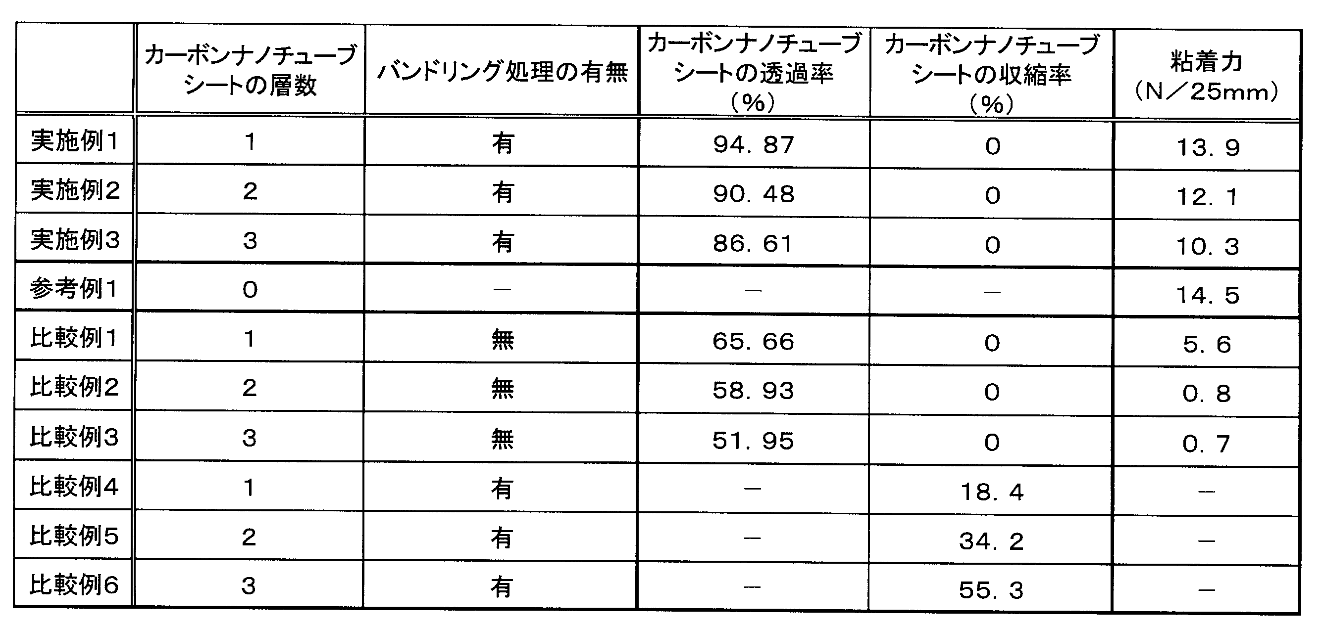
また、本改質方法により得られたカーボンナノチューブシートを用いた本発明の粘着シートは、カーボンナノチューブシートの優れた電気伝導性により、ヒーター等として、好適に用いることができる。
The present invention can be used when modifying a carbon nanotube sheet, for example, improving the light transmittance of the carbon nanotube sheet or reducing the resistance.
Moreover, the pressure-sensitive adhesive sheet of the present invention using the carbon nanotube sheet obtained by the present modification method can be suitably used as a heater or the like due to the excellent electrical conductivity of the carbon nanotube sheet.
Claims (12)
- カーボンナノチューブシートの改質方法であって、
構造体上に一または複数のカーボンナノチューブシートを載置する工程と、
前記構造体上のカーボンナノチューブシートを常温で液体の物質の蒸気または粒子に曝露する工程とを含み、
前記カーボンナノチューブシートは、複数のカーボンナノチューブが、シート面内の一方向に優先的に整列した構造を有し、
前記構造体は、前記カーボンナノチューブシートを載置する載置部を有し、
前記載置部は、前記カーボンナノチューブシートとは接触しない非接触部および前記カーボンナノチューブシートと接触する接触部を有し、
前記非接触部と前記接触部との境界と、載置部の平面視において、前記カーボンナノチューブの整列方向に平行し、かつ非接触部を跨ぐ直線との、非接触部における交点間の最長距離をL1とし、前記非接触部と前記接触部との境界と、載置部の平面視において、前記カーボンナノチューブの整列方向に交差し、かつ非接触部を跨ぐ直線との、非接触部における交点間の最長距離をL2としたとき、
L1がL2よりも大きい場合、少なくともL2は0mm超10mm未満であり、
L1がL2よりも小さい場合、少なくともL1は0mm超10mm未満であり、
L1とL2が等しい場合、L1およびL2は0mm超10mm未満である、
カーボンナノチューブシートの改質方法。 A method of modifying a carbon nanotube sheet,
Placing one or more carbon nanotube sheets on the structure;
Exposing the carbon nanotube sheet on the structure to vapor or particles of a liquid substance at room temperature,
The carbon nanotube sheet has a structure in which a plurality of carbon nanotubes are preferentially aligned in one direction in the sheet surface,
The structure has a placement portion for placing the carbon nanotube sheet,
The placement portion has a non-contact portion that does not contact the carbon nanotube sheet and a contact portion that contacts the carbon nanotube sheet,
The longest distance between the intersections in the non-contact portion of the boundary between the non-contact portion and the contact portion and the straight line parallel to the alignment direction of the carbon nanotubes and straddling the non-contact portion in the plan view of the mounting portion was the L 1, wherein the boundary between the contact part and the non-contact portion, in a plan view of the mounting portion, intersects the alignment direction of the carbon nanotube, and the straight line across the non-contact portion, the non-contact portion when the maximum distance between the intersections was L 2,
If L 1 is greater than L 2 , at least L 2 is greater than 0 mm and less than 10 mm;
When L 1 is smaller than L 2 , at least L 1 is more than 0 mm and less than 10 mm,
When L 1 and L 2 are equal, L 1 and L 2 are greater than 0 mm and less than 10 mm;
A method for modifying a carbon nanotube sheet. - 前記非接触部および前記接触部の少なくともいずれかは、独立して複数存在する、
請求項1に記載のカーボンナノチューブシートの改質方法。 At least one of the non-contact part and the contact part is independently plural,
The method for modifying a carbon nanotube sheet according to claim 1. - 前記非接触部および前記接触部のいずれもが、連続している、
請求項1または請求項2に記載のカーボンナノチューブシートの改質方法。 Both the non-contact part and the contact part are continuous,
The method for modifying a carbon nanotube sheet according to claim 1 or 2. - 前記構造体は、前記非接触部が微細孔を有する、
請求項1から請求項3のいずれか1項に記載のカーボンナノチューブシートの改質方法。 In the structure, the non-contact part has a fine hole,
The method for modifying a carbon nanotube sheet according to any one of claims 1 to 3. - 前記構造体は、前記接触部として、隆起構造を有する、
請求項1から請求項4のいずれか1項に記載のカーボンナノチューブシートの改質方法。 The structure has a raised structure as the contact portion,
The method for modifying a carbon nanotube sheet according to any one of claims 1 to 4. - 前記構造体は、前記最長距離L1が0mm超10mm未満である、
請求項1から請求項5のいずれか1項に記載のカーボンナノチューブシートの改質方法。 The structure, the maximum distance L 1 is less than 0mm super 10 mm,
The method for modifying a carbon nanotube sheet according to any one of claims 1 to 5. - 前記構造体は、連続した複数の接触部と、連続した複数の非接触部とを有し、前記連続した複数の接触部と前記連続した複数の非接触部が、縞状構造を形成し、前記縞状構造が、前記カーボンナノチューブの整列方向に対して前記平面視において交差して、かつ、隣り合う連続した接触部の、対向し合う各々の端部において、一方の端部の任意の一点について、他方の端部の最も近接した点までの距離が常に10mm未満となるように設けられている、
請求項3から請求項6のいずれか1項に記載のカーボンナノチューブシートの改質方法。 The structure has a plurality of continuous contact portions and a plurality of continuous non-contact portions, and the plurality of continuous contact portions and the plurality of continuous non-contact portions form a striped structure, The striped structure intersects with the alignment direction of the carbon nanotubes in the plan view, and at each of the opposing end portions of the adjacent continuous contact portions, any one point of one end portion For the other end, the distance to the closest point is always less than 10 mm,
The method for modifying a carbon nanotube sheet according to any one of claims 3 to 6. - 複数の前記カーボンナノチューブシートを前記構造体上で積層し、その後、前記構造体上の複数の前記カーボンナノチューブシートを、常温で液体の物質の蒸気または粒子に曝露する工程を実施する、
請求項1から請求項7のいずれか1項に記載のカーボンナノチューブシートの改質方法。 Laminating a plurality of the carbon nanotube sheets on the structure, and then performing a step of exposing the plurality of carbon nanotube sheets on the structure to vapor or particles of a liquid substance at room temperature,
The method for modifying a carbon nanotube sheet according to any one of claims 1 to 7. - 改質されたカーボンナノチューブシートの光線透過率が70%以上である請求項1から請求項8のいずれか1項に記載のカーボンナノチューブシートの改質方法。 The method for modifying a carbon nanotube sheet according to any one of claims 1 to 8, wherein the light transmittance of the modified carbon nanotube sheet is 70% or more.
- 請求項1から請求項9のいずれか1項に記載のカーボンナノチューブシートの改質方法により得られる改質されたカーボンナノチューブシートであり、
前記改質されたカーボンナノチューブシートの光線透過率は70%以上である、
改質されたカーボンナノチューブシート。 A modified carbon nanotube sheet obtained by the method of modifying a carbon nanotube sheet according to any one of claims 1 to 9,
The light transmittance of the modified carbon nanotube sheet is 70% or more.
Modified carbon nanotube sheet. - 粘着シートの製造方法であって、
粘着剤を含有する粘着剤層にカーボンナノチューブシートを積層する工程を含み、
前記カーボンナノチューブシートとして、請求項1から請求項9のいずれか1項に記載のカーボンナノチューブシートの改質方法により得られる改質されたカーボンナノチューブシートを用い、
前記改質されたカーボンナノチューブシートの粘着剤層側の面とは反対の面を被着体に貼付して測定した前記粘着シートの粘着力が8N/25mm以上である、
粘着シートの製造方法。 A method of manufacturing an adhesive sheet,
Including a step of laminating a carbon nanotube sheet on an adhesive layer containing an adhesive,
As the carbon nanotube sheet, using a modified carbon nanotube sheet obtained by the carbon nanotube sheet modifying method according to any one of claims 1 to 9,
The adhesive strength of the pressure-sensitive adhesive sheet measured by attaching the surface opposite to the surface on the pressure-sensitive adhesive layer side of the modified carbon nanotube sheet to an adherend is 8 N / 25 mm or more,
A method for producing an adhesive sheet. - 粘着シートであって、
前記粘着シートは、カーボンナノチューブシートと、粘着剤を含有する粘着剤層と、を有し、
前記カーボンナノチューブシートは、請求項1から請求項9のいずれか1項に記載のカーボンナノチューブシートの改質方法により得られる改質されたカーボンナノチューブシートであり、
前記改質されたカーボンナノチューブシートの粘着剤層側の面とは反対の面を被着体に貼付して測定した前記粘着シートの粘着力が8N/25mm以上である、
粘着シート。 An adhesive sheet,
The pressure-sensitive adhesive sheet has a carbon nanotube sheet and a pressure-sensitive adhesive layer containing a pressure-sensitive adhesive,
The carbon nanotube sheet is a modified carbon nanotube sheet obtained by the carbon nanotube sheet modifying method according to any one of claims 1 to 9,
The adhesive strength of the pressure-sensitive adhesive sheet measured by attaching the surface opposite to the surface on the pressure-sensitive adhesive layer side of the modified carbon nanotube sheet to an adherend is 8 N / 25 mm or more,
Adhesive sheet.
Priority Applications (5)
| Application Number | Priority Date | Filing Date | Title |
|---|---|---|---|
| JP2018515719A JP6985254B2 (en) | 2016-05-02 | 2017-04-28 | Method of modifying carbon nanotube sheet |
| KR1020187029911A KR102392846B1 (en) | 2016-05-02 | 2017-04-28 | Method for modifying carbon nanotube sheet, modified carbon nanotube sheet, method for manufacturing pressure-sensitive adhesive sheet, and pressure-sensitive adhesive sheet |
| CN201780027239.XA CN109153573B (en) | 2016-05-02 | 2017-04-28 | Method for modifying carbon nanotube sheet, modified carbon nanotube sheet, method for producing adhesive sheet, and adhesive sheet |
| US16/096,610 US10774243B2 (en) | 2016-05-02 | 2017-04-28 | Method for modifying carbon nanotube sheet, modified carbon nanotube sheet, method for manufacturing adhesive sheet, and adhesive sheet |
| EP17792745.6A EP3453675B1 (en) | 2016-05-02 | 2017-04-28 | Method for modifying carbon nanotube sheet, modified carbon nanotube sheet, method for manufacturing adhesive sheet, and adhesive sheet |
Applications Claiming Priority (2)
| Application Number | Priority Date | Filing Date | Title |
|---|---|---|---|
| US201662330670P | 2016-05-02 | 2016-05-02 | |
| US62/330,670 | 2016-05-02 |
Publications (1)
| Publication Number | Publication Date |
|---|---|
| WO2017191812A1 true WO2017191812A1 (en) | 2017-11-09 |
Family
ID=60202991
Family Applications (1)
| Application Number | Title | Priority Date | Filing Date |
|---|---|---|---|
| PCT/JP2017/016904 WO2017191812A1 (en) | 2016-05-02 | 2017-04-28 | Method for modifying carbon nanotube sheet, modified carbon nanotube sheet, method for manufacturing adhesive sheet, and adhesive sheet |
Country Status (7)
| Country | Link |
|---|---|
| US (1) | US10774243B2 (en) |
| EP (1) | EP3453675B1 (en) |
| JP (1) | JP6985254B2 (en) |
| KR (1) | KR102392846B1 (en) |
| CN (1) | CN109153573B (en) |
| TW (1) | TWI729122B (en) |
| WO (1) | WO2017191812A1 (en) |
Citations (5)
| Publication number | Priority date | Publication date | Assignee | Title |
|---|---|---|---|---|
| WO2009107846A1 (en) * | 2008-02-29 | 2009-09-03 | 独立行政法人産業技術総合研究所 | Carbon nanotube film structure and method for manufacturing the same |
| JP2009208975A (en) * | 2008-02-29 | 2009-09-17 | National Institute Of Advanced Industrial & Technology | Carbon nanotube structure and method for producing the same |
| JP2010215437A (en) * | 2009-03-14 | 2010-09-30 | Taiyo Nippon Sanso Corp | Method and apparatus for continuous synthesis of aligned carbon nanotubes |
| JP2012246210A (en) * | 2011-05-27 | 2012-12-13 | Qinghua Univ | Method for producing graphene/carbon nanotube composite structure |
| JP2014103649A (en) * | 2012-11-20 | 2014-06-05 | Qinghua Univ | Thermoacoustic device and thermoacoustic device array |
Family Cites Families (7)
| Publication number | Priority date | Publication date | Assignee | Title |
|---|---|---|---|---|
| KR101458846B1 (en) * | 2004-11-09 | 2014-11-07 | 더 보드 오브 리전츠 오브 더 유니버시티 오브 텍사스 시스템 | The fabrication and application of nanofiber ribbons and sheets and twisted and non-twisted nanofiber yarns |
| CN101239712B (en) * | 2007-02-09 | 2010-05-26 | 清华大学 | Carbon nano-tube thin film structure and preparation method thereof |
| US9233492B2 (en) | 2010-10-12 | 2016-01-12 | Florida State University Research Foundation, Inc. | Composite materials reinforced with carbon nanotube yarns |
| JP2014084255A (en) * | 2012-10-24 | 2014-05-12 | Hokkaido Univ | Carbon nanotube thin film, transparent electrode and electrode for lithography |
| CN103841500B (en) | 2012-11-20 | 2018-01-30 | 清华大学 | Thermo-acoustic device |
| CN203167267U (en) * | 2012-11-20 | 2013-08-28 | 清华大学 | Thermoacoustic device |
| KR102431014B1 (en) * | 2014-11-21 | 2022-08-09 | 린텍 가부시키가이샤 | Method for producing carbon nanotube sheet, and carbon nanotube sheet |
-
2017
- 2017-04-28 CN CN201780027239.XA patent/CN109153573B/en active Active
- 2017-04-28 EP EP17792745.6A patent/EP3453675B1/en active Active
- 2017-04-28 WO PCT/JP2017/016904 patent/WO2017191812A1/en unknown
- 2017-04-28 US US16/096,610 patent/US10774243B2/en active Active
- 2017-04-28 KR KR1020187029911A patent/KR102392846B1/en active IP Right Grant
- 2017-04-28 JP JP2018515719A patent/JP6985254B2/en active Active
- 2017-05-01 TW TW106114405A patent/TWI729122B/en active
Patent Citations (5)
| Publication number | Priority date | Publication date | Assignee | Title |
|---|---|---|---|---|
| WO2009107846A1 (en) * | 2008-02-29 | 2009-09-03 | 独立行政法人産業技術総合研究所 | Carbon nanotube film structure and method for manufacturing the same |
| JP2009208975A (en) * | 2008-02-29 | 2009-09-17 | National Institute Of Advanced Industrial & Technology | Carbon nanotube structure and method for producing the same |
| JP2010215437A (en) * | 2009-03-14 | 2010-09-30 | Taiyo Nippon Sanso Corp | Method and apparatus for continuous synthesis of aligned carbon nanotubes |
| JP2012246210A (en) * | 2011-05-27 | 2012-12-13 | Qinghua Univ | Method for producing graphene/carbon nanotube composite structure |
| JP2014103649A (en) * | 2012-11-20 | 2014-06-05 | Qinghua Univ | Thermoacoustic device and thermoacoustic device array |
Non-Patent Citations (1)
| Title |
|---|
| See also references of EP3453675A4 * |
Also Published As
| Publication number | Publication date |
|---|---|
| CN109153573A (en) | 2019-01-04 |
| JPWO2017191812A1 (en) | 2019-03-07 |
| EP3453675B1 (en) | 2022-09-07 |
| TW201808797A (en) | 2018-03-16 |
| EP3453675A4 (en) | 2019-12-25 |
| TWI729122B (en) | 2021-06-01 |
| CN109153573B (en) | 2022-04-26 |
| KR20190002453A (en) | 2019-01-08 |
| US10774243B2 (en) | 2020-09-15 |
| KR102392846B1 (en) | 2022-04-29 |
| JP6985254B2 (en) | 2021-12-22 |
| US20190136094A1 (en) | 2019-05-09 |
| EP3453675A1 (en) | 2019-03-13 |
Similar Documents
| Publication | Publication Date | Title |
|---|---|---|
| TWI824186B (en) | Sheet, heating element and heating device | |
| JP5820762B2 (en) | Surface protective film for transparent conductive film and transparent conductive film using the same | |
| JP7321164B2 (en) | METHOD FOR MANUFACTURING ARTICLE WITH CONDUCTIVE SHEET | |
| JP2004346302A (en) | Self-adhesive tape or sheet and manufacturing method thereof | |
| CN113196419B (en) | Conductive adhesive sheet, laminate, and heat-generating device | |
| JP6811705B2 (en) | Adhesive sheet | |
| WO2016136686A1 (en) | Adhesive sheet | |
| JP2020119856A (en) | Manufacturing method of sheet-like conductive member, and sheet-like conductive member | |
| WO2017191812A1 (en) | Method for modifying carbon nanotube sheet, modified carbon nanotube sheet, method for manufacturing adhesive sheet, and adhesive sheet | |
| JP5884608B2 (en) | Method for producing double-sided adhesive tape | |
| JP2016190326A (en) | Release sheet and adhesive sheet | |
| WO2020189173A1 (en) | Sheet-shaped conductive member and manufacturing method therefor | |
| JP7308210B2 (en) | Sheet-shaped conductive member | |
| JP2018172614A (en) | Adhesive sheet | |
| WO2022070481A1 (en) | Wiring sheet and wiring sheet production method | |
| JP2018172613A (en) | Adhesive sheet | |
| JP2023055662A (en) | Adhesive member | |
| JP2022085213A (en) | Wiring sheet and method for manufacturing the same | |
| JP6623098B2 (en) | Adhesive sheet for glass dicing and method for producing the same | |
| JP4381057B2 (en) | Adhesive tape or sheet and method for producing the same | |
| KR20200043982A (en) | Polymer thin film, film-like laminate, and method for manufacturing polymer thin film | |
| JP2005220180A (en) | Adhesive tape or sheet | |
| JP2005194482A (en) | Releasing agent composition, releasing sheet and adhesive |
Legal Events
| Date | Code | Title | Description |
|---|---|---|---|
| ENP | Entry into the national phase |
Ref document number: 2018515719 Country of ref document: JP Kind code of ref document: A |
|
| ENP | Entry into the national phase |
Ref document number: 20187029911 Country of ref document: KR Kind code of ref document: A |
|
| NENP | Non-entry into the national phase |
Ref country code: DE |
|
| 121 | Ep: the epo has been informed by wipo that ep was designated in this application |
Ref document number: 17792745 Country of ref document: EP Kind code of ref document: A1 |
|
| ENP | Entry into the national phase |
Ref document number: 2017792745 Country of ref document: EP Effective date: 20181203 |