EP3453675B1 - Method for modifying carbon nanotube sheet, modified carbon nanotube sheet, method for manufacturing adhesive sheet, and adhesive sheet - Google Patents
Method for modifying carbon nanotube sheet, modified carbon nanotube sheet, method for manufacturing adhesive sheet, and adhesive sheet Download PDFInfo
- Publication number
- EP3453675B1 EP3453675B1 EP17792745.6A EP17792745A EP3453675B1 EP 3453675 B1 EP3453675 B1 EP 3453675B1 EP 17792745 A EP17792745 A EP 17792745A EP 3453675 B1 EP3453675 B1 EP 3453675B1
- Authority
- EP
- European Patent Office
- Prior art keywords
- carbon nanotube
- nanotube sheet
- sheet
- contacting
- assembly
- Prior art date
- Legal status (The legal status is an assumption and is not a legal conclusion. Google has not performed a legal analysis and makes no representation as to the accuracy of the status listed.)
- Active
Links
- OKTJSMMVPCPJKN-UHFFFAOYSA-N Carbon Chemical compound [C] OKTJSMMVPCPJKN-UHFFFAOYSA-N 0.000 title claims description 307
- 239000002041 carbon nanotube Substances 0.000 title claims description 295
- 229910021393 carbon nanotube Inorganic materials 0.000 title claims description 295
- 239000000853 adhesive Substances 0.000 title description 159
- 230000001070 adhesive effect Effects 0.000 title description 89
- 238000000034 method Methods 0.000 title description 40
- 238000004519 manufacturing process Methods 0.000 title description 7
- 238000002715 modification method Methods 0.000 claims description 40
- 239000011148 porous material Substances 0.000 claims description 26
- 239000007788 liquid Substances 0.000 claims description 16
- 239000000126 substance Substances 0.000 claims description 15
- 239000002245 particle Substances 0.000 claims description 12
- 238000010030 laminating Methods 0.000 claims description 10
- NIXOWILDQLNWCW-UHFFFAOYSA-M Acrylate Chemical compound [O-]C(=O)C=C NIXOWILDQLNWCW-UHFFFAOYSA-M 0.000 description 40
- 239000000178 monomer Substances 0.000 description 31
- 230000008569 process Effects 0.000 description 31
- 230000000052 comparative effect Effects 0.000 description 23
- 239000000470 constituent Substances 0.000 description 23
- 229920000058 polyacrylate Polymers 0.000 description 17
- 239000003795 chemical substances by application Substances 0.000 description 15
- 239000002184 metal Substances 0.000 description 14
- KFZMGEQAYNKOFK-UHFFFAOYSA-N Isopropanol Chemical compound CC(C)O KFZMGEQAYNKOFK-UHFFFAOYSA-N 0.000 description 12
- 239000000463 material Substances 0.000 description 12
- 239000004971 Cross linker Substances 0.000 description 11
- 229920005989 resin Polymers 0.000 description 11
- 239000011347 resin Substances 0.000 description 11
- -1 tackifier Substances 0.000 description 11
- XEKOWRVHYACXOJ-UHFFFAOYSA-N Ethyl acetate Chemical compound CCOC(C)=O XEKOWRVHYACXOJ-UHFFFAOYSA-N 0.000 description 8
- 229920006243 acrylic copolymer Polymers 0.000 description 8
- 239000000123 paper Substances 0.000 description 8
- 125000000217 alkyl group Chemical group 0.000 description 7
- 238000012986 modification Methods 0.000 description 7
- 230000004048 modification Effects 0.000 description 7
- 230000000712 assembly Effects 0.000 description 6
- 238000000429 assembly Methods 0.000 description 6
- 239000000758 substrate Substances 0.000 description 6
- 239000003522 acrylic cement Substances 0.000 description 5
- 239000000443 aerosol Substances 0.000 description 5
- 125000004432 carbon atom Chemical group C* 0.000 description 5
- 239000000835 fiber Substances 0.000 description 5
- 239000000203 mixture Substances 0.000 description 5
- 239000007787 solid Substances 0.000 description 5
- 239000011248 coating agent Substances 0.000 description 4
- 238000000576 coating method Methods 0.000 description 4
- 230000000694 effects Effects 0.000 description 4
- 229920001971 elastomer Polymers 0.000 description 4
- 229960004592 isopropanol Drugs 0.000 description 4
- 239000002985 plastic film Substances 0.000 description 4
- 229920006255 plastic film Polymers 0.000 description 4
- 229920000139 polyethylene terephthalate Polymers 0.000 description 4
- 239000005020 polyethylene terephthalate Substances 0.000 description 4
- 238000002834 transmittance Methods 0.000 description 4
- ZWEHNKRNPOVVGH-UHFFFAOYSA-N 2-Butanone Chemical compound CCC(C)=O ZWEHNKRNPOVVGH-UHFFFAOYSA-N 0.000 description 3
- LFQSCWFLJHTTHZ-UHFFFAOYSA-N Ethanol Chemical compound CCO LFQSCWFLJHTTHZ-UHFFFAOYSA-N 0.000 description 3
- OKKJLVBELUTLKV-UHFFFAOYSA-N Methanol Chemical compound OC OKKJLVBELUTLKV-UHFFFAOYSA-N 0.000 description 3
- 239000000654 additive Substances 0.000 description 3
- 230000000996 additive effect Effects 0.000 description 3
- 125000003178 carboxy group Chemical group [H]OC(*)=O 0.000 description 3
- 125000004122 cyclic group Chemical group 0.000 description 3
- 235000019439 ethyl acetate Nutrition 0.000 description 3
- 125000002887 hydroxy group Chemical group [H]O* 0.000 description 3
- 230000006872 improvement Effects 0.000 description 3
- 238000005259 measurement Methods 0.000 description 3
- 125000004108 n-butyl group Chemical group [H]C([H])([H])C([H])([H])C([H])([H])C([H])([H])* 0.000 description 3
- 239000003960 organic solvent Substances 0.000 description 3
- 238000002360 preparation method Methods 0.000 description 3
- 239000005060 rubber Substances 0.000 description 3
- SMZOUWXMTYCWNB-UHFFFAOYSA-N 2-(2-methoxy-5-methylphenyl)ethanamine Chemical compound COC1=CC=C(C)C=C1CCN SMZOUWXMTYCWNB-UHFFFAOYSA-N 0.000 description 2
- NIXOWILDQLNWCW-UHFFFAOYSA-N 2-Propenoic acid Natural products OC(=O)C=C NIXOWILDQLNWCW-UHFFFAOYSA-N 0.000 description 2
- 125000000954 2-hydroxyethyl group Chemical group [H]C([*])([H])C([H])([H])O[H] 0.000 description 2
- CSCPPACGZOOCGX-UHFFFAOYSA-N Acetone Chemical compound CC(C)=O CSCPPACGZOOCGX-UHFFFAOYSA-N 0.000 description 2
- XKRFYHLGVUSROY-UHFFFAOYSA-N Argon Chemical compound [Ar] XKRFYHLGVUSROY-UHFFFAOYSA-N 0.000 description 2
- JOYRKODLDBILNP-UHFFFAOYSA-N Ethyl urethane Chemical compound CCOC(N)=O JOYRKODLDBILNP-UHFFFAOYSA-N 0.000 description 2
- VZCYOOQTPOCHFL-OWOJBTEDSA-N Fumaric acid Chemical compound OC(=O)\C=C\C(O)=O VZCYOOQTPOCHFL-OWOJBTEDSA-N 0.000 description 2
- RRHGJUQNOFWUDK-UHFFFAOYSA-N Isoprene Chemical compound CC(=C)C=C RRHGJUQNOFWUDK-UHFFFAOYSA-N 0.000 description 2
- CERQOIWHTDAKMF-UHFFFAOYSA-N Methacrylic acid Chemical compound CC(=C)C(O)=O CERQOIWHTDAKMF-UHFFFAOYSA-N 0.000 description 2
- 239000004698 Polyethylene Substances 0.000 description 2
- XUIMIQQOPSSXEZ-UHFFFAOYSA-N Silicon Chemical compound [Si] XUIMIQQOPSSXEZ-UHFFFAOYSA-N 0.000 description 2
- PPBRXRYQALVLMV-UHFFFAOYSA-N Styrene Chemical compound C=CC1=CC=CC=C1 PPBRXRYQALVLMV-UHFFFAOYSA-N 0.000 description 2
- 150000001298 alcohols Chemical class 0.000 description 2
- 125000003277 amino group Chemical group 0.000 description 2
- 229920001577 copolymer Polymers 0.000 description 2
- 125000004093 cyano group Chemical group *C#N 0.000 description 2
- 230000003247 decreasing effect Effects 0.000 description 2
- 125000002704 decyl group Chemical group [H]C([H])([H])C([H])([H])C([H])([H])C([H])([H])C([H])([H])C([H])([H])C([H])([H])C([H])([H])C([H])([H])C([H])([H])* 0.000 description 2
- 125000003438 dodecyl group Chemical group [H]C([H])([H])C([H])([H])C([H])([H])C([H])([H])C([H])([H])C([H])([H])C([H])([H])C([H])([H])C([H])([H])C([H])([H])C([H])([H])C([H])([H])* 0.000 description 2
- 125000003700 epoxy group Chemical group 0.000 description 2
- 150000002148 esters Chemical class 0.000 description 2
- 238000011156 evaluation Methods 0.000 description 2
- 239000011888 foil Substances 0.000 description 2
- 125000000524 functional group Chemical group 0.000 description 2
- 230000001788 irregular Effects 0.000 description 2
- 125000000959 isobutyl group Chemical group [H]C([H])([H])C([H])(C([H])([H])[H])C([H])([H])* 0.000 description 2
- 239000012948 isocyanate Substances 0.000 description 2
- 150000002513 isocyanates Chemical class 0.000 description 2
- 150000002576 ketones Chemical class 0.000 description 2
- ANISOHQJBAQUQP-UHFFFAOYSA-N octyl prop-2-enoate Chemical compound CCCCCCCCOC(=O)C=C ANISOHQJBAQUQP-UHFFFAOYSA-N 0.000 description 2
- 238000012856 packing Methods 0.000 description 2
- 229920000573 polyethylene Polymers 0.000 description 2
- 238000004080 punching Methods 0.000 description 2
- 229910052710 silicon Inorganic materials 0.000 description 2
- 239000010703 silicon Substances 0.000 description 2
- 239000013077 target material Substances 0.000 description 2
- 238000012360 testing method Methods 0.000 description 2
- VZCYOOQTPOCHFL-UHFFFAOYSA-N trans-butenedioic acid Natural products OC(=O)C=CC(O)=O VZCYOOQTPOCHFL-UHFFFAOYSA-N 0.000 description 2
- 238000009827 uniform distribution Methods 0.000 description 2
- DTGKSKDOIYIVQL-WEDXCCLWSA-N (+)-borneol Chemical group C1C[C@@]2(C)[C@@H](O)C[C@@H]1C2(C)C DTGKSKDOIYIVQL-WEDXCCLWSA-N 0.000 description 1
- XLPJNCYCZORXHG-UHFFFAOYSA-N 1-morpholin-4-ylprop-2-en-1-one Chemical compound C=CC(=O)N1CCOCC1 XLPJNCYCZORXHG-UHFFFAOYSA-N 0.000 description 1
- RNFJDJUURJAICM-UHFFFAOYSA-N 2,2,4,4,6,6-hexaphenoxy-1,3,5-triaza-2$l^{5},4$l^{5},6$l^{5}-triphosphacyclohexa-1,3,5-triene Chemical compound N=1P(OC=2C=CC=CC=2)(OC=2C=CC=CC=2)=NP(OC=2C=CC=CC=2)(OC=2C=CC=CC=2)=NP=1(OC=1C=CC=CC=1)OC1=CC=CC=C1 RNFJDJUURJAICM-UHFFFAOYSA-N 0.000 description 1
- JAHNSTQSQJOJLO-UHFFFAOYSA-N 2-(3-fluorophenyl)-1h-imidazole Chemical compound FC1=CC=CC(C=2NC=CN=2)=C1 JAHNSTQSQJOJLO-UHFFFAOYSA-N 0.000 description 1
- SXIFAEWFOJETOA-UHFFFAOYSA-N 4-hydroxy-butyl Chemical group [CH2]CCCO SXIFAEWFOJETOA-UHFFFAOYSA-N 0.000 description 1
- NLHHRLWOUZZQLW-UHFFFAOYSA-N Acrylonitrile Chemical compound C=CC#N NLHHRLWOUZZQLW-UHFFFAOYSA-N 0.000 description 1
- 238000012935 Averaging Methods 0.000 description 1
- NOWKCMXCCJGMRR-UHFFFAOYSA-N Aziridine Chemical compound C1CN1 NOWKCMXCCJGMRR-UHFFFAOYSA-N 0.000 description 1
- 239000004593 Epoxy Substances 0.000 description 1
- YCKRFDGAMUMZLT-UHFFFAOYSA-N Fluorine atom Chemical compound [F] YCKRFDGAMUMZLT-UHFFFAOYSA-N 0.000 description 1
- CERQOIWHTDAKMF-UHFFFAOYSA-M Methacrylate Chemical compound CC(=C)C([O-])=O CERQOIWHTDAKMF-UHFFFAOYSA-M 0.000 description 1
- 239000004743 Polypropylene Substances 0.000 description 1
- OFOBLEOULBTSOW-UHFFFAOYSA-N Propanedioic acid Natural products OC(=O)CC(O)=O OFOBLEOULBTSOW-UHFFFAOYSA-N 0.000 description 1
- XTXRWKRVRITETP-UHFFFAOYSA-N Vinyl acetate Chemical compound CC(=O)OC=C XTXRWKRVRITETP-UHFFFAOYSA-N 0.000 description 1
- 150000001252 acrylic acid derivatives Chemical class 0.000 description 1
- 150000001336 alkenes Chemical class 0.000 description 1
- 125000005370 alkoxysilyl group Chemical group 0.000 description 1
- 229920000180 alkyd Polymers 0.000 description 1
- HSFWRNGVRCDJHI-UHFFFAOYSA-N alpha-acetylene Natural products C#C HSFWRNGVRCDJHI-UHFFFAOYSA-N 0.000 description 1
- 239000002518 antifoaming agent Substances 0.000 description 1
- 239000003429 antifungal agent Substances 0.000 description 1
- 229940121375 antifungal agent Drugs 0.000 description 1
- 239000003963 antioxidant agent Substances 0.000 description 1
- 230000003078 antioxidant effect Effects 0.000 description 1
- 238000013459 approach Methods 0.000 description 1
- 229910052786 argon Inorganic materials 0.000 description 1
- 230000008901 benefit Effects 0.000 description 1
- 125000001797 benzyl group Chemical group [H]C1=C([H])C([H])=C(C([H])=C1[H])C([H])([H])* 0.000 description 1
- 229920001400 block copolymer Polymers 0.000 description 1
- CQEYYJKEWSMYFG-UHFFFAOYSA-N butyl acrylate Chemical compound CCCCOC(=O)C=C CQEYYJKEWSMYFG-UHFFFAOYSA-N 0.000 description 1
- 229910052799 carbon Inorganic materials 0.000 description 1
- 239000012159 carrier gas Substances 0.000 description 1
- 239000000919 ceramic Substances 0.000 description 1
- 239000013522 chelant Substances 0.000 description 1
- 238000005229 chemical vapour deposition Methods 0.000 description 1
- 150000001875 compounds Chemical class 0.000 description 1
- 238000004132 cross linking Methods 0.000 description 1
- 238000002425 crystallisation Methods 0.000 description 1
- 230000008025 crystallization Effects 0.000 description 1
- 125000000113 cyclohexyl group Chemical group [H]C1([H])C([H])([H])C([H])([H])C([H])(*)C([H])([H])C1([H])[H] 0.000 description 1
- 230000002950 deficient Effects 0.000 description 1
- 238000000280 densification Methods 0.000 description 1
- 239000000806 elastomer Substances 0.000 description 1
- 238000004049 embossing Methods 0.000 description 1
- 125000001495 ethyl group Chemical group [H]C([H])([H])C([H])([H])* 0.000 description 1
- 125000002534 ethynyl group Chemical group [H]C#C* 0.000 description 1
- 239000000945 filler Substances 0.000 description 1
- 239000003063 flame retardant Substances 0.000 description 1
- 239000011737 fluorine Substances 0.000 description 1
- 229910052731 fluorine Inorganic materials 0.000 description 1
- 239000001530 fumaric acid Substances 0.000 description 1
- 239000007789 gas Substances 0.000 description 1
- 239000011521 glass Substances 0.000 description 1
- 230000009477 glass transition Effects 0.000 description 1
- 239000011086 glassine Substances 0.000 description 1
- 125000003055 glycidyl group Chemical group C(C1CO1)* 0.000 description 1
- 229920000578 graft copolymer Polymers 0.000 description 1
- 238000004050 hot filament vapor deposition Methods 0.000 description 1
- 150000003949 imides Chemical class 0.000 description 1
- 230000003993 interaction Effects 0.000 description 1
- VZCYOOQTPOCHFL-UPHRSURJSA-N maleic acid Chemical compound OC(=O)\C=C/C(O)=O VZCYOOQTPOCHFL-UPHRSURJSA-N 0.000 description 1
- 239000011976 maleic acid Substances 0.000 description 1
- 125000002496 methyl group Chemical group [H]C([H])([H])* 0.000 description 1
- LVHBHZANLOWSRM-UHFFFAOYSA-N methylenebutanedioic acid Natural products OC(=O)CC(=C)C(O)=O LVHBHZANLOWSRM-UHFFFAOYSA-N 0.000 description 1
- 239000003607 modifier Substances 0.000 description 1
- 239000002121 nanofiber Substances 0.000 description 1
- JRZJOMJEPLMPRA-UHFFFAOYSA-N olefin Natural products CCCCCCCC=C JRZJOMJEPLMPRA-UHFFFAOYSA-N 0.000 description 1
- 230000003287 optical effect Effects 0.000 description 1
- 230000000704 physical effect Effects 0.000 description 1
- 239000004014 plasticizer Substances 0.000 description 1
- 229920002857 polybutadiene Polymers 0.000 description 1
- 229920001707 polybutylene terephthalate Polymers 0.000 description 1
- 229920005668 polycarbonate resin Polymers 0.000 description 1
- 239000004431 polycarbonate resin Substances 0.000 description 1
- 229920000728 polyester Polymers 0.000 description 1
- 229920006267 polyester film Polymers 0.000 description 1
- 229920001225 polyester resin Polymers 0.000 description 1
- 239000004645 polyester resin Substances 0.000 description 1
- 229920006290 polyethylene naphthalate film Polymers 0.000 description 1
- 229920001721 polyimide Polymers 0.000 description 1
- 239000009719 polyimide resin Substances 0.000 description 1
- 229920000098 polyolefin Polymers 0.000 description 1
- 229920005672 polyolefin resin Polymers 0.000 description 1
- 229920001155 polypropylene Polymers 0.000 description 1
- 229920001296 polysiloxane Polymers 0.000 description 1
- 229920002635 polyurethane Polymers 0.000 description 1
- 239000004814 polyurethane Substances 0.000 description 1
- 229920005749 polyurethane resin Polymers 0.000 description 1
- 229920001289 polyvinyl ether Polymers 0.000 description 1
- 239000003755 preservative agent Substances 0.000 description 1
- 230000002335 preservative effect Effects 0.000 description 1
- 125000001436 propyl group Chemical group [H]C([*])([H])C([H])([H])C([H])([H])[H] 0.000 description 1
- 239000008262 pumice Substances 0.000 description 1
- 229920005604 random copolymer Polymers 0.000 description 1
- 238000005488 sandblasting Methods 0.000 description 1
- 239000013464 silicone adhesive Substances 0.000 description 1
- 229920002050 silicone resin Polymers 0.000 description 1
- 239000002904 solvent Substances 0.000 description 1
- 238000005507 spraying Methods 0.000 description 1
- 125000004079 stearyl group Chemical group [H]C([*])([H])C([H])([H])C([H])([H])C([H])([H])C([H])([H])C([H])([H])C([H])([H])C([H])([H])C([H])([H])C([H])([H])C([H])([H])C([H])([H])C([H])([H])C([H])([H])C([H])([H])C([H])([H])C([H])([H])C([H])([H])[H] 0.000 description 1
- 238000002230 thermal chemical vapour deposition Methods 0.000 description 1
- 229920005992 thermoplastic resin Polymers 0.000 description 1
- 125000002889 tridecyl group Chemical group [H]C([*])([H])C([H])([H])C([H])([H])C([H])([H])C([H])([H])C([H])([H])C([H])([H])C([H])([H])C([H])([H])C([H])([H])C([H])([H])C([H])([H])C([H])([H])[H] 0.000 description 1
- 239000006097 ultraviolet radiation absorber Substances 0.000 description 1
- XLYOFNOQVPJJNP-UHFFFAOYSA-N water Substances O XLYOFNOQVPJJNP-UHFFFAOYSA-N 0.000 description 1
Images


Classifications
-
- C—CHEMISTRY; METALLURGY
- C09—DYES; PAINTS; POLISHES; NATURAL RESINS; ADHESIVES; COMPOSITIONS NOT OTHERWISE PROVIDED FOR; APPLICATIONS OF MATERIALS NOT OTHERWISE PROVIDED FOR
- C09J—ADHESIVES; NON-MECHANICAL ASPECTS OF ADHESIVE PROCESSES IN GENERAL; ADHESIVE PROCESSES NOT PROVIDED FOR ELSEWHERE; USE OF MATERIALS AS ADHESIVES
- C09J7/00—Adhesives in the form of films or foils
- C09J7/20—Adhesives in the form of films or foils characterised by their carriers
- C09J7/29—Laminated material
-
- C—CHEMISTRY; METALLURGY
- C01—INORGANIC CHEMISTRY
- C01B—NON-METALLIC ELEMENTS; COMPOUNDS THEREOF; METALLOIDS OR COMPOUNDS THEREOF NOT COVERED BY SUBCLASS C01C
- C01B32/00—Carbon; Compounds thereof
- C01B32/15—Nano-sized carbon materials
- C01B32/158—Carbon nanotubes
- C01B32/168—After-treatment
-
- C—CHEMISTRY; METALLURGY
- C09—DYES; PAINTS; POLISHES; NATURAL RESINS; ADHESIVES; COMPOSITIONS NOT OTHERWISE PROVIDED FOR; APPLICATIONS OF MATERIALS NOT OTHERWISE PROVIDED FOR
- C09J—ADHESIVES; NON-MECHANICAL ASPECTS OF ADHESIVE PROCESSES IN GENERAL; ADHESIVE PROCESSES NOT PROVIDED FOR ELSEWHERE; USE OF MATERIALS AS ADHESIVES
- C09J7/00—Adhesives in the form of films or foils
- C09J7/30—Adhesives in the form of films or foils characterised by the adhesive composition
-
- C—CHEMISTRY; METALLURGY
- C01—INORGANIC CHEMISTRY
- C01B—NON-METALLIC ELEMENTS; COMPOUNDS THEREOF; METALLOIDS OR COMPOUNDS THEREOF NOT COVERED BY SUBCLASS C01C
- C01B32/00—Carbon; Compounds thereof
- C01B32/15—Nano-sized carbon materials
- C01B32/158—Carbon nanotubes
- C01B32/16—Preparation
-
- C—CHEMISTRY; METALLURGY
- C09—DYES; PAINTS; POLISHES; NATURAL RESINS; ADHESIVES; COMPOSITIONS NOT OTHERWISE PROVIDED FOR; APPLICATIONS OF MATERIALS NOT OTHERWISE PROVIDED FOR
- C09J—ADHESIVES; NON-MECHANICAL ASPECTS OF ADHESIVE PROCESSES IN GENERAL; ADHESIVE PROCESSES NOT PROVIDED FOR ELSEWHERE; USE OF MATERIALS AS ADHESIVES
- C09J201/00—Adhesives based on unspecified macromolecular compounds
-
- C—CHEMISTRY; METALLURGY
- C09—DYES; PAINTS; POLISHES; NATURAL RESINS; ADHESIVES; COMPOSITIONS NOT OTHERWISE PROVIDED FOR; APPLICATIONS OF MATERIALS NOT OTHERWISE PROVIDED FOR
- C09J—ADHESIVES; NON-MECHANICAL ASPECTS OF ADHESIVE PROCESSES IN GENERAL; ADHESIVE PROCESSES NOT PROVIDED FOR ELSEWHERE; USE OF MATERIALS AS ADHESIVES
- C09J7/00—Adhesives in the form of films or foils
- C09J7/10—Adhesives in the form of films or foils without carriers
-
- C—CHEMISTRY; METALLURGY
- C09—DYES; PAINTS; POLISHES; NATURAL RESINS; ADHESIVES; COMPOSITIONS NOT OTHERWISE PROVIDED FOR; APPLICATIONS OF MATERIALS NOT OTHERWISE PROVIDED FOR
- C09J—ADHESIVES; NON-MECHANICAL ASPECTS OF ADHESIVE PROCESSES IN GENERAL; ADHESIVE PROCESSES NOT PROVIDED FOR ELSEWHERE; USE OF MATERIALS AS ADHESIVES
- C09J7/00—Adhesives in the form of films or foils
- C09J7/20—Adhesives in the form of films or foils characterised by their carriers
-
- C—CHEMISTRY; METALLURGY
- C09—DYES; PAINTS; POLISHES; NATURAL RESINS; ADHESIVES; COMPOSITIONS NOT OTHERWISE PROVIDED FOR; APPLICATIONS OF MATERIALS NOT OTHERWISE PROVIDED FOR
- C09J—ADHESIVES; NON-MECHANICAL ASPECTS OF ADHESIVE PROCESSES IN GENERAL; ADHESIVE PROCESSES NOT PROVIDED FOR ELSEWHERE; USE OF MATERIALS AS ADHESIVES
- C09J7/00—Adhesives in the form of films or foils
- C09J7/30—Adhesives in the form of films or foils characterised by the adhesive composition
- C09J7/38—Pressure-sensitive adhesives [PSA]
- C09J7/381—Pressure-sensitive adhesives [PSA] based on macromolecular compounds obtained by reactions involving only carbon-to-carbon unsaturated bonds
- C09J7/385—Acrylic polymers
-
- C—CHEMISTRY; METALLURGY
- C09—DYES; PAINTS; POLISHES; NATURAL RESINS; ADHESIVES; COMPOSITIONS NOT OTHERWISE PROVIDED FOR; APPLICATIONS OF MATERIALS NOT OTHERWISE PROVIDED FOR
- C09J—ADHESIVES; NON-MECHANICAL ASPECTS OF ADHESIVE PROCESSES IN GENERAL; ADHESIVE PROCESSES NOT PROVIDED FOR ELSEWHERE; USE OF MATERIALS AS ADHESIVES
- C09J9/00—Adhesives characterised by their physical nature or the effects produced, e.g. glue sticks
- C09J9/02—Electrically-conducting adhesives
-
- C—CHEMISTRY; METALLURGY
- C01—INORGANIC CHEMISTRY
- C01B—NON-METALLIC ELEMENTS; COMPOUNDS THEREOF; METALLOIDS OR COMPOUNDS THEREOF NOT COVERED BY SUBCLASS C01C
- C01B2202/00—Structure or properties of carbon nanotubes
- C01B2202/08—Aligned nanotubes
-
- C—CHEMISTRY; METALLURGY
- C01—INORGANIC CHEMISTRY
- C01P—INDEXING SCHEME RELATING TO STRUCTURAL AND PHYSICAL ASPECTS OF SOLID INORGANIC COMPOUNDS
- C01P2004/00—Particle morphology
- C01P2004/01—Particle morphology depicted by an image
- C01P2004/02—Particle morphology depicted by an image obtained by optical microscopy
-
- C—CHEMISTRY; METALLURGY
- C01—INORGANIC CHEMISTRY
- C01P—INDEXING SCHEME RELATING TO STRUCTURAL AND PHYSICAL ASPECTS OF SOLID INORGANIC COMPOUNDS
- C01P2006/00—Physical properties of inorganic compounds
- C01P2006/60—Optical properties, e.g. expressed in CIELAB-values
-
- C—CHEMISTRY; METALLURGY
- C08—ORGANIC MACROMOLECULAR COMPOUNDS; THEIR PREPARATION OR CHEMICAL WORKING-UP; COMPOSITIONS BASED THEREON
- C08K—Use of inorganic or non-macromolecular organic substances as compounding ingredients
- C08K3/00—Use of inorganic substances as compounding ingredients
- C08K3/02—Elements
- C08K3/04—Carbon
- C08K3/041—Carbon nanotubes
-
- C—CHEMISTRY; METALLURGY
- C09—DYES; PAINTS; POLISHES; NATURAL RESINS; ADHESIVES; COMPOSITIONS NOT OTHERWISE PROVIDED FOR; APPLICATIONS OF MATERIALS NOT OTHERWISE PROVIDED FOR
- C09J—ADHESIVES; NON-MECHANICAL ASPECTS OF ADHESIVE PROCESSES IN GENERAL; ADHESIVE PROCESSES NOT PROVIDED FOR ELSEWHERE; USE OF MATERIALS AS ADHESIVES
- C09J2301/00—Additional features of adhesives in the form of films or foils
- C09J2301/20—Additional features of adhesives in the form of films or foils characterized by the structural features of the adhesive itself
- C09J2301/206—Additional features of adhesives in the form of films or foils characterized by the structural features of the adhesive itself the adhesive layer comprising non-adhesive protrusions
-
- C—CHEMISTRY; METALLURGY
- C09—DYES; PAINTS; POLISHES; NATURAL RESINS; ADHESIVES; COMPOSITIONS NOT OTHERWISE PROVIDED FOR; APPLICATIONS OF MATERIALS NOT OTHERWISE PROVIDED FOR
- C09J—ADHESIVES; NON-MECHANICAL ASPECTS OF ADHESIVE PROCESSES IN GENERAL; ADHESIVE PROCESSES NOT PROVIDED FOR ELSEWHERE; USE OF MATERIALS AS ADHESIVES
- C09J2301/00—Additional features of adhesives in the form of films or foils
- C09J2301/30—Additional features of adhesives in the form of films or foils characterized by the chemical, physicochemical or physical properties of the adhesive or the carrier
- C09J2301/314—Additional features of adhesives in the form of films or foils characterized by the chemical, physicochemical or physical properties of the adhesive or the carrier the adhesive layer and/or the carrier being conductive
-
- C—CHEMISTRY; METALLURGY
- C09—DYES; PAINTS; POLISHES; NATURAL RESINS; ADHESIVES; COMPOSITIONS NOT OTHERWISE PROVIDED FOR; APPLICATIONS OF MATERIALS NOT OTHERWISE PROVIDED FOR
- C09J—ADHESIVES; NON-MECHANICAL ASPECTS OF ADHESIVE PROCESSES IN GENERAL; ADHESIVE PROCESSES NOT PROVIDED FOR ELSEWHERE; USE OF MATERIALS AS ADHESIVES
- C09J2301/00—Additional features of adhesives in the form of films or foils
- C09J2301/40—Additional features of adhesives in the form of films or foils characterized by the presence of essential components
- C09J2301/408—Additional features of adhesives in the form of films or foils characterized by the presence of essential components additives as essential feature of the adhesive layer
-
- C—CHEMISTRY; METALLURGY
- C09—DYES; PAINTS; POLISHES; NATURAL RESINS; ADHESIVES; COMPOSITIONS NOT OTHERWISE PROVIDED FOR; APPLICATIONS OF MATERIALS NOT OTHERWISE PROVIDED FOR
- C09J—ADHESIVES; NON-MECHANICAL ASPECTS OF ADHESIVE PROCESSES IN GENERAL; ADHESIVE PROCESSES NOT PROVIDED FOR ELSEWHERE; USE OF MATERIALS AS ADHESIVES
- C09J2301/00—Additional features of adhesives in the form of films or foils
- C09J2301/40—Additional features of adhesives in the form of films or foils characterized by the presence of essential components
- C09J2301/41—Additional features of adhesives in the form of films or foils characterized by the presence of essential components additives as essential feature of the carrier layer
-
- C—CHEMISTRY; METALLURGY
- C09—DYES; PAINTS; POLISHES; NATURAL RESINS; ADHESIVES; COMPOSITIONS NOT OTHERWISE PROVIDED FOR; APPLICATIONS OF MATERIALS NOT OTHERWISE PROVIDED FOR
- C09J—ADHESIVES; NON-MECHANICAL ASPECTS OF ADHESIVE PROCESSES IN GENERAL; ADHESIVE PROCESSES NOT PROVIDED FOR ELSEWHERE; USE OF MATERIALS AS ADHESIVES
- C09J2400/00—Presence of inorganic and organic materials
- C09J2400/10—Presence of inorganic materials
- C09J2400/12—Ceramic
- C09J2400/123—Ceramic in the substrate
-
- C—CHEMISTRY; METALLURGY
- C09—DYES; PAINTS; POLISHES; NATURAL RESINS; ADHESIVES; COMPOSITIONS NOT OTHERWISE PROVIDED FOR; APPLICATIONS OF MATERIALS NOT OTHERWISE PROVIDED FOR
- C09J—ADHESIVES; NON-MECHANICAL ASPECTS OF ADHESIVE PROCESSES IN GENERAL; ADHESIVE PROCESSES NOT PROVIDED FOR ELSEWHERE; USE OF MATERIALS AS ADHESIVES
- C09J2433/00—Presence of (meth)acrylic polymer
Definitions
- the present invention relates to a modification method of a carbon nanotube sheet.
- Such a carbon nanotube sheet possesses unique characteristics such as electrical conductivity, exothermicity and in-plane anisotropy.
- Patent Literature 1 discloses a nanofiber sheet including carbon nanotubes.
- US 2011/111177 A1 discloses a modification method for CNT sheets comprising a densification step.
- the carbon nanotubes are obtained on a wafer substrate and then detached by e.g. using tweezers.
- the obtained CNT sheet is positioned on a specific second wafer substrate which has been produced separately and which contains a plurality of pillars. Pillar distances disclosed in D2 are 4 ⁇ m, 10 ⁇ m and 1 ⁇ m, respectively.
- Patent Literature 1 JP 2008-523254 A
- the carbon nanotube sheet is occasionally subjected to a treatment such as exposure to liquid vapor.
- An object of the invention is to provide a modification method for preventing shrinkage of a carbon nanotube sheet in a width direction thereof at the time of subjecting the carbon nanotube sheet to treatment such as exposure to liquid vapor.
- a modification method of a carbon nanotube sheet includes: mounting at least one carbon nanotube sheet on an assembly; and exposing the carbon nanotube sheet on the assembly to steam or particles of a substance that is liquid at room temperature.
- the carbon nanotube sheet has a structure in which a plurality of carbon nanotubes are aligned preferentially in one direction in a plane of the sheet.
- the assembly includes a mounting section on which the carbon nanotube sheet is mounted.
- the mounting section includes a non-contacting section that is not brought into contact with the carbon nanotube sheet and a contacting section that is brought into contact with the carbon nanotube sheet.
- L 1 is defined by a maximum distance in the non-contacting section between intersection points of a straight line extending across the non-contacting section in parallel with an alignment direction of the carbon nanotubes in a plan view of the mounting section with a border between the non-contacting section and the contacting section
- L 2 is defined by a maximum distance in the non-contacting section between intersection points of a straight line extending across the non-contacting section and intersecting with the alignment direction of the carbon nanotubes in the plan view of the mounting section with the border between the non-contacting section and the contacting section.
- L 1 is larger than L 2 , at least L 2 is more than 10 ⁇ m and 5mm or less, when L 1 is smaller than L 2 , at least L 1 is more than 10 ⁇ m and 5 mm or less, and when L 1 is equal to L 2 , each of L 1 and L 2 is more than 10 ⁇ m and 5 mm or less.
- At least one of the non-contacting section and the contacting section is separately disposed at plural positions.
- the non-contacting section includes a plurality of continuous non-contacting sections and the contacting section includes a plurality of continuous contacting sections.
- the non-contacting section of the assembly has fine pores.
- the assembly includes a bumpy structure as the contacting sections.
- the maximum distance L 1 is more than 10 ⁇ m and 5 mm or less in the assembly.
- the assembly preferably includes a plurality of continuous contacting sections and a plurality of continuous non-contacting sections.
- the continuous contacting sections and the continuous non-contacting sections form a striped arrangement, in which a distance between closest two points, one of the two points being a point on one of facing ends of adjacent ones of the continuous contacting sections and the other of the two points being a point on the other one of the facing ends, is always less than 5 mm, and the striped arrangement crosses the alignment direction of the carbon nanotubes in the plan view.
- the carbon nanotube sheet including a plurality of carbon nanotube sheets may be laminated on the assembly, and then the plurality of carbon nanotube sheets on the assembly may be exposed to the steam or particles of the substance that is liquid at room temperature.
- the light transmissivity of a modified carbon nanotube sheet is 70% or more.
- a modification method of a carbon nanotube sheet of a first exemplary embodiment (hereinafter, also referred to as “the present modification method”) will be described hereinbelow.
- the present modification method includes a process of mounting one or two or more carbon nanotube sheets on an assembly (hereinafter, also referred to as “mounting process” for the sake of the convenience) and a process of exposing the carbon nanotube sheet on the assembly to steam or particles of a substance that is liquid at room temperature (hereinafter, also referred to as “exposure process” for the sake of the convenience).
- the carbon nanotube sheet of the first exemplary embodiment has a structure in which a plurality of carbon nanotubes are preferentially aligned in one direction defined in a plane of the sheet.
- the structure in which the carbon nanotubes are aligned in one direction defined in a plane of the sheet herein means that the carbon nanotubes are aligned along one direction defined in a plane of the sheet. For instance, longitudinal axes of the carbon nanotubes are aligned in parallel with one direction defined in a plane of the sheet.
- the carbon nanotubes are preferentially aligned” herein means that the aligned state of the carbon nanotubes is mainstream.
- the longitudinal axes of the carbon nanotubes are aligned in parallel with one direction defined in a plane of the sheet as described above, the longitudinal axes of a part of the carbon nanotubes need not be aligned in parallel with one direction defined in a plane of the sheet as long as the aligned state of the carbon nanotubes is mainstream.
- the carbon nanotube sheet is produced by, for instance, drawing carbon nanotubes agglomerated by an intermolecular force into a sheet from a carbon nanotube forest (i.e., a grown form, which is occasionally referred to as "array", of a plurality of carbon nanotubes grown on a substrate to be vertically aligned relative to a principal surface of the substrate) and separating the drawn carbon nanotubes from the substrate.
- a carbon nanotube forest i.e., a grown form, which is occasionally referred to as "array”
- array of a plurality of carbon nanotubes grown on a substrate to be vertically aligned relative to a principal surface of the substrate
- the carbon nanotube sheet is mounted on the assembly.
- a single-layered carbon nanotube sheet may be mounted on the assembly, or a multi-layered sheet obtained by preliminarily laminating a plurality of carbon nanotube sheets may be mounted on the assembly.
- the assembly according to the present modification method includes a mounting section on which the carbon nanotube sheet is mounted.
- the mounting section of the assembly has a non-contacting section that is not brought into contact with the carbon nanotube sheet and a contacting section that is brought into contact with the carbon nanotube sheet.
- a straight line extending in parallel with the alignment direction of the carbon nanotubes in a plan view of the mounting section and crossing over the non-contacting section defines intersection points across the non-contacting section with a border between the non-contacting section and the contacting section.
- a maximum distance between the intersection points is denoted by L 1 .
- a straight line intersecting with the alignment direction of the carbon nanotubes in the plan view of the mounting section and crossing over the non-contacting section defines intersection points across the non-contacting section with the border between the non-contacting section and the contacting section.
- a maximum distance between the intersection points is denoted by L 2 .
- L 1 is larger than L 2
- at least L 2 is more than 10 ⁇ m and 5 mm or less.
- at least L 1 is more than 10 ⁇ m and 5 mm or less.
- L 1 is equal to L 2
- each of L 1 and L 2 is more than 10 ⁇ m and 5 mm or less.
- L 2 when L 1 is larger than L 2 , at least L 2 is preferably 50 ⁇ m or more and 2 mm or less, and further preferably 100 ⁇ m or more and 1.5 mm or less.
- L 1 when L 1 is smaller than L 2 , at least L 1 is preferably 50 ⁇ m or more and 2 mm or less, and further preferably 100 ⁇ m or more and 1.5 mm or less.
- each of L 1 and L 2 is preferably 50 ⁇ m or more and 2 mm or less, and further preferably 100 ⁇ m or more and 1.5 mm or less.
- At least one of the non-contacting section and the contacting section is separately disposed at plural positions.
- the shape of the non-contacting section is not particularly limited.
- the shape of the non-contacting section may be, for example, a square, oblong, rectangle, circle, oval, honeycomb, comb teeth, linear, curved, wavy (e.g., sine curve) and a net consisting of polygons, or the non-contacting section may be in an irregular shape. Alternatively, as described later, the non-contacting section may have fine pores.
- the minimum distance between adjacent ones of the separately disposed contacting sections i.e., a distance of closest approach between ends of the adjacent contacting sections
- the minimum distance between adjacent ones of the separately disposed contacting sections is more than 10 ⁇ m and less 5 mm or less.
- the plurality of carbon nanotubes which are preferentially aligned in one direction defined in a plane of the sheet are bundled around the alignment direction in the exposure process described later. Since the plurality of contacting sections which are separated from each other are densely present along the alignment direction, a distance between ends of the sheet fixed by the contacting sections at the time of bundling the carbon nanotubes is reduced.
- the minimum distance between adjacent ones of the separately disposed contacting sections in the plan view of the mounting section is 50 ⁇ m or more and 2 mm or less, further preferably 100 ⁇ m or more and 1.5 mm or less.
- the shape of the contacting section is not particularly limited.
- the shape of the contacting section may be, for example, a square, oblong, rectangle, circle, oval, curved, wavy (e.g., sine curve) and polygon, or the contacting section may be in an irregular shape.
- “bundling” means a state that the plurality of carbon nanotubes close to each other constituting the carbon nanotube sheet are bundled (i.e., gathered into the form of fibers).
- bundling treatment the treatment of bundling the carbon nanotubes of the carbon nanotube sheet.
- the maximum distance L 2 is defined on a straight line intersecting with the alignment direction of the carbon nanotubes in the carbon nanotube sheet with an angle in a range from 60 to 90 degrees in the plan view of the mounting section, whereas the maximum distance L 2 is always more than 10 ⁇ m and 5 mm or less. It is more preferable that the maximum distance L 2 is defined on a straight line substantially perpendicular to the alignment direction of the carbon nanotubes in the carbon nanotube sheet (i.e., intersecting with the alignment direction of the carbon nanotubes in the carbon nanotube sheet with an angle in a range from 80 to 90 degrees) (see Fig. 1 regarding the case of 90 degrees), whereas the maximum distance L 2 is always more than 10 ⁇ m to 5 mm or less.
- the maximum distance L 1 is more than 10 ⁇ m and5 mm or less.
- the maximum distance between the adjacent contacting sections i.e., the widest gap between the ends of the adjacent contacting sections
- the maximum distance between the adjacent contacting sections in the alignment direction of the carbon nanotubes is more than 10 ⁇ m and 5 mm or less.
- a length of a straight line segment, which is randomly drawn on the surface of the assembly so as to be in parallel with the alignment direction of the carbon nanotubes, between the adjacent contacting sections is more than 10 ⁇ m and 5mm or less (see Fig. 1 ).
- the carbon nanotube sheet a plurality of carbon nanotubes which are preferentially aligned in one direction defined in a plane of the sheet are bundled around the alignment direction in the exposure process described later. Since the distance between the adjacent contacting sections in the alignment direction is 5 mm or less, the distance between the ends of the sheet fixed by the contacting sections at the time of bundling the plurality of carbon nanotubes is reduced. As a result, the number of the carbon nanotubes to be bundled becomes appropriate, and a uniform distribution of the carbon nanotubes is easily maintained.
- the maximum distance between the adjacent contacting sections in the alignment direction of the carbon nanotubes is preferably whereas the 50 ⁇ m or more and 2 mm or less, further preferably 100 ⁇ m or more and 1.5 mm or less.
- the bundling of the carbon nanotubes is not performed in the carbon nanotube sheet corresponding to the contacting sections in the exposure process. Accordingly, in order to increase the ratio of the area subjected to the bundling treatment relative to the total area of the carbon nanotube sheet, it is necessary to relatively reduce the area of the contacting sections in the assembly. In view of the above, the distance between the adjacent non-contacting sections in the alignment direction of the carbon nanotubes is more than 10 ⁇ m and less than 5 mm.
- a length of a straight line segment, which is randomly drawn on the surface of the assembly (i.e., surface having the mounting section) so as to be in parallel with the alignment direction of the carbon nanotubes, between the adjacent non-contacting sections is preferably more than 10 ⁇ m and less than 5 mm.
- the distance between the adjacent non-contacting sections in the alignment direction of the carbon nanotubes is preferably more than 10 ⁇ m and 2 mm or less, more preferably 50 ⁇ m or more and 1 mm or less, and further preferably 100 ⁇ m or more and 500 ⁇ m or less.
- a straight line segment which is randomly drawn on the surface of the assembly so as to be in parallel with the alignment direction of the carbon nanotubes herein includes a straight line segment which is randomly drawn on only part of the surface of the assembly so as to be in parallel with the alignment direction of the carbon nanotubes as long as an effect of the invention can be achieved.
- each of the maximum distances L 1 and L 2 is more than 10 ⁇ m and 5 mm or less.
- an assembly in which each of the non-contacting sections has fine pores is used, for example.
- fine pore herein means pores each having an opening diameter (minimum diameter) of 5 mm or less.
- an assembly in which each of the non-contacting sections has fine pores may be adopted in a second exemplary embodiment described later, such an assembly may also be adopted in the first exemplary embodiment so that the assembly in which at least one of the non-contacting section and the contacting section is separately disposed at plural positions can be easily obtained.
- the opening diameter of each of the fine pores is 5 mm or less, more preferably 2 mm or less, further preferably 1.5 mm or less.
- a lower limit of the opening diameter of the fine pores is more than 10 ⁇ m or more, and may be appropriately determined in view of the light transmissivity, adhesive force and the like of the carbon nanotube sheet.
- the shape of the opening of the fine pore is not particularly specified.
- the maximum diameter of the fine pores is preferably in a range more than 10 ⁇ m to 5 mm or less.
- the assembly according to the present modification method may be an assembly including a plurality of fine pores and the contacting sections continuous with each other or an assembly including a plurality of fine pores and the contacting sections separated from each other.
- contacting sections continuous with each other herein means that the contacting section is not closed by the non-contacting section in a plan view of the mounting section. It should be noted that, “non-contacting sections continuous with each other” herein means that the non-contacting section is not closed by the contacting section in a plan view of the mounting section.
- the assembly of the first exemplary embodiment may be in the shape of a mesh, net, punching, embossing, lattice, or combination of them, for example. More specifically, examples of the assembly including the plurality of fine pores and the contacting sections continuous with each other include a sponge, a macroporous material (e.g., pumice, macroporous ceramic and the like), a honeycomb porous assembly and a metal foil processed by punching. In these assemblies, the non-contacting sections each including fine pores are separated from each other.
- a macroporous material e.g., pumice, macroporous ceramic and the like
- examples of the assembly including the plurality of fine pores and the plurality of contacting sections separated from each other include metal mesh and a planar sphere packing assembly.
- the non-contacting sections each including fine pores are continuous with each other.
- a known means such as 3D printer may be used to form the assembly including the fine pores.
- Fig. 2 schematically illustrates another example of assemblies according to the first exemplary embodiment, which is a partially broken view of a carbon nanotube sheet 5A supported by an assembly 1A in the shape of a mesh.
- the assembly 1A in the shape of a mesh includes a plurality of fine pores 2A defining a lattice pattern.
- L 1 is a minimum diameter (opening diameter) of the fine pore 2A.
- the assembly 1A in the shape of a mesh has a bumpy structure in which threads constituting the mesh are patterned.
- the bumpy structure at the side on which the carbon nanotube sheet 5A is mounted defines a contacting section 3A that is in contact with the carbon nanotube sheet 5A (see Fig. 3 ).
- the carbon nanotube sheet 5A mounted on the assembly 1A in the shape of a mesh is exposed to steam or particles (aerosol) of a substance that is liquid at a room temperature (referred to as "room-temperature liquid substance” hereinafter).
- the carbon nanotubes of the carbon nanotube sheet 5A can be bundled.
- room temperature herein means 25 degrees C.
- Examples of the room-temperature liquid substances according to the first exemplary embodiment include water and an organic solvent.
- Examples of the organic solvent include alcohols, ketones and esters.
- Examples of the alcohols include ethanol, methanol and isopropylalcohol.
- Examples of the ketones include acetone and methyl ethyl ketone.
- Examples of the esters include acetic ether.
- a method for exposing the carbon nanotube sheet 5A mounted on the assembly 1A in the shape of a mesh to steam or particles (aerosol) of a room-temperature liquid substance there are a method in which a room-temperature liquid substance is sprayed onto the carbon nanotube sheet 5A mounted on the assembly 1A in the shape of a mesh, and a method in which aerosol of a room-temperature liquid substance is generated using a supersonic humidifier or the like and then the carbon nanotube sheet 5A mounted on the assembly 1A in the shape of a mesh is exposed in the generated aerosol, for example.
- a particle size of the room-temperature liquid substance (obtained by extracting ten particles stuck to the carbon nanotube sheet 5A at random, observing the extracted ten particles using an electron microscope and averaging the major diameters thereof) is preferably in a range from 5 nm to 200 ⁇ m, more preferably in a range from 7.5 nm to 100 ⁇ m, further preferably in a range from 10 nm to 50 ⁇ m.
- an average diameter of the structure in which the carbon nanotubes are gathered into the form of fibers is preferably in a range from 1 ⁇ m to 300 ⁇ m, more preferably in a range from 3 ⁇ m to 150 ⁇ m, further preferably in a range from 5 ⁇ m to 50 ⁇ m.
- the average diameter of the structure in which the carbon nanotubes are gathered into the form of fibers herein means an average diameter of the outer circumferences of the structures.
- the contacting section 3A defined by the bumpy structure in which the threads constituting the mesh of the assembly 1A in the shape of a mesh are patterned is brought into contact with the carbon nanotube sheet 5A, the carbon nanotubes of a portion of the carbon nanotube sheet 5A in contact with the contacting section 3A are not bundled, and the carbon nanotubes of a portion of the carbon nanotube sheet 5A not in contact with the contacting section 3A (i.e., the fine pores 2A of the assembly 1A in the shape of a mesh and a portion corresponding to a root of the bumpy structure of the threads constituting the mesh) are bundled (see Fig. 4 ).
- the carbon nanotube sheet 5A is subjected to the bundling treatment in a free standing state (in a state that the carbon nanotube sheet is not mounted on a support structure of some sort, i.e., self-supported), shrinkage of the carbon nanotube sheet 5A in the width direction becomes outstanding.
- the carbon nanotube sheet 5A is subjected to the bundling treatment on the assembly 1A in the shape of a mesh having the plurality of fine pores (i.e., the non-contacting section having a predetermined opening diameter) 2A in the plan view of the mounting section 4A, so that occurrence of shrinkage of the carbon nanotube sheet 5A in the width direction is prevented.
- the plurality of carbon nanotubes close to each other are bundled, and thereby voids are generated in the carbon nanotube sheet 5A.
- the light transmittance of the carbon nanotube sheet 5A is improved. Additionally, an effect such as decrease in the sheet resistance can be exhibited.
- the carbon nanotube sheet when the carbon nanotube sheet is mounted on a support structure having no non-contacting sections and subjected to a treatment such as exposure to liquid vapor or the like, an entire surface of the carbon nanotube sheet near the support structure is brought into contact with the support structure. Accordingly, even when being subjected to a treatment of some sort, the carbon nanotube sheet only moves toward the support structure (in a thickness direction of the carbon nanotube sheet), and the carbon nanotubes are not gathered into a form of fibers. Consequently, an effect such as improvement in the light transmissivity and decrease in the sheet resistance cannot be exhibited.
- a portion in which the bundling treatment is performed and a portion in which the bundling treatment is not performed can be formed on the carbon nanotube sheet.
- a carbon nanotube sheet which is modified in terms of light transmittance, sheet resistance and the like, for example, can be obtained.
- the light transmissivity of the modified carbon nanotube sheet is preferably 70 % or more.
- the carbon nanotube sheet can be suitably used for a vehicle window that is required to allow for the visibility, a mirror that is required to provide an image with sharpness and the like, for example.
- the light transmissivity of the carbon nanotube sheet can be improved by, for example, increasing the area of voids in the carbon nanotube sheet.
- an area of the non-contacting section may be enlarged by increasing the opening diameter of each of the fine pores in the assembly, for example.
- the light transmissivity of the modified carbon nanotube sheet is preferably in a range from 70% to 100%, more preferably in a range from 80% to 99.9%.
- the light transmissivity may be measured using an optical transmissivity measuring instrument including a visible-ultraviolet light source and a spectrometer, for example.
- Adhesive Sheet (not according to the invention)
- Fig. 5 is a schematic cross-sectional view of an adhesive sheet 10(not according to the invention) according to the first exemplary embodiment.
- the adhesive sheet 10 (not according to the invention) according to the first exemplary embodiment includes a carbon nanotube sheet 11 and an adhesive agent layer 12 containing an adhesive agent.
- a first surface 11a of the carbon nanotube sheet 11 (hereinafter, occasionally referred to as "first sheet surface 11a") is adjacent to a first surface 12a of the adhesive agent layer 12 (hereinafter, occasionally referred to as "first adhesive surface 12a").
- the carbon nanotube sheet 11 is a carbon nanotube sheet subjected to the bundling treatment, which is obtained by the above-described modification method of a carbon nanotube sheet of the first exemplary embodiment. Accordingly, it is possible to improve the light transmittance of the carbon nanotube sheet 11.
- a thickness t 11 of the carbon nanotube sheet 11 is appropriately determined depending on the intended use of the adhesive sheet 10.
- a thickness t 11 of the carbon nanotube sheet 11 is preferably in a range from 0.01 ⁇ m to 100 ⁇ m, more preferably in a range from 0.05 ⁇ m to 75 ⁇ m.
- Adhesive Agent Layer (not according to the invention)
- the adhesive agent of the adhesive agent layer 12 is not particularly limited.
- the adhesive agent include acrylic adhesive agent, urethane adhesive agent, rubber adhesive agent, polyester adhesive agent, silicone adhesive agent and polyvinylether adhesive agent.
- the adhesive agent of the adhesive agent layer 12 is preferably at least one selected from the group consisting of acrylic adhesive agent, urethane adhesive agent and rubber adhesive agent, more preferably an acrylic adhesive agent.
- the acrylic adhesive agent includes acrylic polymer.
- the acrylic polymer includes a constituent unit derived from alkyl(meth)acrylate having a straight or branched alkyl group, a constituent unit derived from (meth)acrylate having a cyclic structure, or the like, for example. It should be noted that “(meth)acrylate” includes “acrylate” and “methacrylate”, and the same applies to the other similar terms.
- the acrylic polymer includes a constituent unit (a1) derived from an alkyl(meth)acrylate (a1') having an alkyl group with 1 to 20 carbon atoms (hereinafter, also referred to as "monomer component (a1')”), a constituent unit (a2) derived from a functional-group-containing monomer (a2') (hereinafter, also referred to as “monomer component (a2')”), and a constituent unit (a3) derived from another monomer component (a3') different from the monomer component (a1') and the monomer component (a2').
- a1' alkyl(meth)acrylate
- a2' having an alkyl group with 1 to 20 carbon atoms
- a constituent unit (a2) derived from a functional-group-containing monomer (a2')
- a3' derived from another monomer component (a3') different from the monomer component (a1') and the monomer component (a2').
- the acrylic polymer may be a copolymer including at least one of the constituent unit (a1) and the constituent unit (a2), and two or more selected from the constituent units (a1) to (a3).
- the type of the copolymer is not particularly limited, but may be a block copolymer, a random copolymer or a graft copolymer.
- the alkyl group in the monomer component (a1') preferably has 1 to 18 carbon atoms, more preferably has 2 to 14 carbon atoms, further preferably has 4 to 12 carbon atoms in terms of improvement in the adhesiveness and the like.
- the carbon atoms of the alkyl group in the monomer component (a1') is within the above range, the interaction between the main chains of the acrylic polymer is disturbed and an influence of crystallization of the side chains is reduced to be small. Accordingly, a glass transition temperature of the acrylic polymer is maintained to be low, and the adhesiveness of the adhesive agent is easily improvable.
- second sheet surface 11b (hereinafter occasionally referred to as "second sheet surface 11b")
- Examples of the monomer component (a1') include methyl(meth)acrylate, ethyl(meth)acrylate, propyl(meth)acrylate, n-butyl(meth)acrylate, isobutyl(meth)acrylate, 2-ethylhexyl(meth)acrylate, n-octyl acrylate, isooctyl(meth)acrylate, decyl(meth)acrylate, lauryl(meth)acrylate, tridecyl(meth)acrylate and stearyl(meth)acrylate.
- n-butyl(meth)acrylate, isobutyl(meth)acrylate, 2-ethylhexyl(meth)acrylate, n-octyl acrylate, isooctyl(meth)acrylate, decyl(meth)acrylate and lauryl(meth)acrylate are preferable, and n-butyl(meth)acrylate and 2-ethylhexyl(meth)acrylate are more preferable.
- the content of the constituent unit (a1) relative to the total constituent units (100 mass%) of the acrylic copolymer is preferably in a range from 50 mass% to 99.5 mass%, more preferably in a range from 55 mass% to 99 mass%, further preferably in a range from 60 mass% to 97 mass%, still more preferably in a range from 65 mass% to 95 mass%.
- Examples of the monomer component (a2') include a hydroxy-group-containing monomer, carboxy-group-containing monomer, epoxy-group-containing monomer, amino-group-containing monomer, cyano-group-containing monomer, keto-group-containing monomer, and alkoxysilyl-group-containing monomer.
- hydroxy-group-containing monomer and carboxy-group-containing monomer are preferable.
- hydroxy-group-containing monomer examples include 2-hydroxyethyl(meth)acrylate, 2-hydroxylpropyl(meth)acrylate, 2-hydroxybutyl(meth)acrylate, 3-hydroxybutyl(meth)acrylate and 4-hydroxybutyl(meth)acrylate, among which 2-hydroxyethyl(meth)acrylate is preferable.
- Examples of the carboxy-group-containing monomer include a (meth)acrylic acid, maleic acid, fumaric acid and itaconic acid, among which a (meth)acrylic acid is preferable.
- Examples of the epoxy-group-containing monomer include glycidyl(meth)acrylate.
- Examples of the amino-group-containing monomer include diaminoethyl(meth)acrylate.
- Examples of the cyano-group-containing monomer include acrylonitrile.
- the acrylic polymer is an acrylic copolymer including at least the constituent unit (a2), and in addition to this, at least one or more selected from the constituent units (a1) and (a3)
- the content of the constituent unit (a2) relative to the total constituent units (100 mass%) of the acrylic copolymer is preferably in a range from 0.1 mass% to 50 mass%, more preferably in a range from 0.5 mass% to 40 mass%, further preferably in a range from 1.0 mass% to 30 mass%, still more preferably in a range from 1.5 mass% to 20 mass%.
- Examples of the monomer component (a3') include (meth)acrylate having a cyclic structure, vinyl acetate, and styrene.
- Examples of (meth)acrylates having a cyclic structure include cyclohexyl(meth)acrylate, benzyl(meth)acrylate, isobornyl(meth)acrylate, dicyclopentanyl(meth)acrylate, dicyclopentenyl(meth)acrylate, dicyclopentenyloxyethyl(meth)acrylate, imide(meth)acrylate and acryloylmorpholine.
- the content of the constituent unit (a3) relative to the total constituent units (100 mass%) of the acrylic copolymer is preferably more than 0 mass% and 40 mass% or less, more preferably more than 0 mass% and 30 mass% or less, further preferably more than 0 mass% and 25 mass% or less, still more preferably more than 0 mass% and 20 mass% or less.
- one of the above monomer components (a1') may be singularly used or two or more thereof may be used in combination
- one of the above monomer components (a2') may be singularly used or two or more thereof may be used in combination
- one of the above monomer components (a3') may be singularly used or two or more thereof may be used in combination.
- the weight-average molecular weight of the acrylic polymer is preferably in a range from 50,000 to 2,500,000, more preferably in a range from 100,000 to 1,500,000.
- the adhesive agent tends to be softened, and the adhesiveness of the adhesive agent tends to be increased.
- the weight-average molecular weight of acrylic polymer is adjusted within the above-described range, so that it becomes easier to control the adhesive force.
- the acrylic polymer may be cross-linked.
- a cross linker may be a known epoxy cross-linker, isocyanate cross-linker, aziridine cross-linker, metal chelate cross-linker or the like.
- the functional group derived from the monomer component (a2') may be used as a cross-linking point where the acrylic polymer is reacted with the cross-linker. It sometimes occurs that the sole use of the constituent unit (a2) is insufficient to easily control the physical property of the acrylic polymer. Therefore, in such a case, it is preferable that the acrylic polymer is an acrylic copolymer including the constituent unit (a2) and at least one of the constituent units (a1) and (a3).
- the additive amount of the cross linker in general, as an additive amount of the cross linker becomes smaller, the adhesive agent tends to be softened, and the adhesiveness of the adhesive agent tends to be increased.
- the additive amount of the cross linker relative to 100 parts by mass of the acrylic copolymer is preferably 0.01 to 15 parts by mass, more preferably 0.05 to 10 parts by mass.
- the additive amount of the cross linker may be adjusted within the above-described range, so as to easily control the adhesive force.
- the composition for forming the adhesive agent layer 12 may contain additional component(s).
- additional component(s) to be contained in the composition for forming the adhesive agent layer include organic solvent, flame retardant, tackifier, ultraviolet absorber, antioxidant, preservative, antifungal agent, plasticizer, antifoaming agent and wettability modifier.
- tackifier When the tackifier is used, it becomes easier to adjust the adhesive force of the adhesive sheet 10 measured after sticking the second sheet surface 11b to the adherend within a range described later.
- the content of the tackifier is preferably 1 to 300 parts by mass relative to 100 parts by mass of the acrylic adhesive agent.
- a thickness t 12 of the adhesive agent layer 12 (see Fig. 5 ) is appropriately determined depending on the intended use of the adhesive sheet 10.
- the thickness t 12 of the adhesive agent layer 12 formed on the first sheet surface 11a of the carbon nanotube sheet 11 is adjusted in a range from 3 ⁇ m to 150 ⁇ m, preferably in a range from 5 ⁇ m to 100 ⁇ m.
- t 12 is preferably in a range from 1 ⁇ m to 20 ⁇ m, more preferably in a range from 2 ⁇ m to 9 ⁇ m.
- the adhesive force of the adhesive sheet 10 measured after sticking the second sheet surface 11b to the adherend is preferably 8 N/25mm or more.
- the adhesive force is more preferably 9 N/25mm or more, further preferably 9.5 N/25mm or more.
- an upper limit of the adhesive force of the adhesive sheet 10 measured after sticking the second sheet surface 11b of the carbon nanotube sheet 11 on the adherend is not particularly specified, the upper limit is usually approximately 35 N/25mm or less.
- the adhesive force herein is a value obtained by measuring the adhesive force after the elapse of 30 minutes from the adhesion of the adhesive sheet 10 with the pulling rate of 300 mm/min. and the sheet width of 25 mm by 180-degree peeling method according to JIS Z0237:2000.
- the adhesive force of the adhesive sheet 10 measured after sticking the second sheet surface 11b to the adherend is usually influenced by extensibility of the adhesive agent layer 12 in the absence of the base.
- a polyethylene terephthalate film having a thickness of 25 ⁇ m as a base is stuck to a surface of the adhesive agent layer 12 opposite to the surface adjacent to the carbon nanotube sheet 11 (second surface 12b (hereinafter, occasionally referred to as "second adhesive surface 12b")) to obtain a sample, and an adhesive force of the sample is measured.
- second adhesive surface 12b second surface 12b
- the plurality of carbon nanotubes close to each other are bundled. Consequently, voids are generated in the carbon nanotube sheet.
- the adhesive agent in the adhesive agent layer on the second sheet surface 11b increasingly exudes through the voids. Accordingly, it becomes easier to adjust the adhesive force of the adhesive sheet 10 measured after sticking the second sheet surface 11b to the adherend within the range described above.
- a production method of the adhesive sheet 10 (not according to the invention) of the first exemplary embodiment includes a process of laminating a carbon nanotube sheet on an adhesive agent layer containing an adhesive agent.
- the production method of the adhesive sheet 10 is not particularly limited except the above-described process.
- the adhesive sheet 10 is produced through the following processes.
- a forest of carbon nanotubes is first formed on a substrate such as a silicon wafer by a known method. Subsequently, an end of the formed forest is twisted and drawn with tweezers or the like to produce the carbon nanotube sheet. Then, the produced carbon nanotube sheet is subjected to the modification method of the first exemplary embodiment to obtain the carbon nanotube sheet 11.
- An adhesive agent layer is produced independently of the carbon nanotube sheet 11.
- the adhesive agent is first applied on a release sheet to form a coating film.
- the coating film is then dried to produce the adhesive agent layer 12.
- the first sheet surface 11a of the carbon nanotube sheet 11 is stuck to (laminated on) the first adhesive surface 12a of the produced adhesive agent layer 12. Subsequently, the release sheet is removed to provide the adhesive sheet 10.
- the adhesive sheet 10 (not according to the invention) of the first exemplary embodiment improves the handleability of the carbon nanotube sheet, and enables the carbon nanotube sheet to be easily applicable to a variety of uses.
- a second exemplary embodiment is different from the first exemplary embodiment in that an assembly in which a mounting section includes contacting sections continuous with each other and non-contacting sections continuous with each other is used as an assembly according to the modification method of a carbon nanotube sheet in the second exemplary embodiment.
- the second exemplary embodiment is the same as the first exemplary embodiment in other points, the description thereof is omitted or simplified.
- the assembly according to the modification method of the second exemplary embodiment includes a plurality of continuous contacting sections (hereinafter, also referred to as "plurality of supporters") and a plurality of continuous non-contacting sections.
- the contacting sections and the non-contacting sections are arranged in stripes.
- the plurality of supporters which are, for instance, arranged in stripes, intersect with the alignment direction of the carbon nanotubes in the carbon nanotube sheet in a plan view of the mounting section.
- a preferable angle defined between each of the plurality of supporters and the alignment direction of the carbon nanotubes is in a range from 60 to 90 degrees.
- the plurality of supporters are substantially perpendicular to the alignment direction of the carbon nanotubes (i.e., intersect with the alignment direction of the carbon nanotubes with an angle therebetween in a range from 80 to 90 degrees).
- the maximum distance between the closest two points, one of the two points being a point on one of facing ends of adjacent ones of the contacting section and the other of the two points being a point on the other one of the facing ends, is always 5 mm or less.
- Lines constituting the stripes may be straight lines, wavy lines, curved lines, or bent lines, for example.
- the maximum distance between the closest two points, one of the two points being a point on one of facing ends of adjacent ones of the contacting section and the other of the two points being a point on the other one of the facing ends is preferably 2 mm or less, further preferably 1.5 mm or less.
- a lower limit of the maximum distance between the adjacent supporters among the plurality of supporters is 10 ⁇ m or more, and may be determined as desired in view of the light transmissivity, adhesive force and the like of the carbon nanotube sheet.
- the lower limit of the maximum distance between the adjacent supporters among the plurality of supporters is preferably 50 ⁇ m or more, more preferably 100 ⁇ m or more.
- the maximum distance L 1 is more than 10 ⁇ m and 5 mm or less in the assembly as in the first exemplary embodiment described above.
- Such a structure can be easily obtained under the conditions that, when the plurality of supporters and the continuous non-contacting sections are arranged in stripes, the maximum distance between the closest two points, one of the two points being a point on one of facing ends of adjacent ones of the contacting section and the other of the two points being a point on the other one of the facing ends, is always 5 mm or less and the plurality of supporters are substantially perpendicular to the alignment direction of the carbon nanotubes in the carbon nanotube sheet in a plan view of the mounting section.
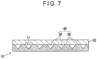
- Fig. 6 schematically illustrates an example of an assembly according to the second exemplary embodiment, which shows part of the carbon nanotube sheet 5B supported by an assembly 1B having a plurality of continuous contacting sections 2B as a broken view.
- the assembly 1B according to the modification method of the second exemplary embodiment includes a plurality of continuous contacting section 2B and continuous non-contacting sections 3B
- the plurality of contacting sections 2B are perpendicular to the alignment direction of the carbon nanotubes in the carbon nanotube sheet 5B in a plan view of a mounting section 4B (see Fig. 7 ).
- the distance L 1 between the adjacent contacting sections 2B is as noted above.
- the carbon nanotube sheet 5B mounted on the assembly 1B comes in contact with the contacting sections 2B (see Fig. 7 ).
- the assembly on which the carbon nanotube sheet is mounted may be an assembly including a bumpy structure defined by a plurality of independent contacting sections and the continuous non-contacting sections.
- Such an assembly is exemplified by a structure having a plurality of needles, a structure having a plurality of pillars and a structure in which a bumpy structure having a gentle slope or the like is erected on a base body.
- distal ends of the bumpy structure or the like defining the contacting sections which are in contact with the carbon nanotube sheet are preferably flat or curved.
- Examples of the shape of the needle or the pillar include a cylinder and a cone.
- the assembly on which the carbon nanotube sheet is mounted may be a film provided with irregularities by sandblasting and addition of filler, or an emboss film.
- an assembly including the plurality of fine pores and the plurality of contacting sections separated from each other, such as a metal mesh and a planar sphere packing assembly, also has the bumpy structure.
- Examples of the assembly on which the carbon nanotube is mounted according to the first exemplary embodiment include, in addition to the assembly having fine pores and the assembly having the bumpy structure, an assembly that is an emboss film having continuous flat untreated sections as the contacting sections and a plurality of concaves separate from each other as the non-contacting section.
- one carbon nanotube sheet or a plurality of carbon nanotube sheets laminated in advance are mounted on the assembly, and then subjected to the exposure process.
- the plurality of carbon nanotube sheets may be laminated on the assembly and then subjected to the exposure process.
- the effect of preventing shrinkage of the carbon nanotube sheets in the width direction is further enhanced.
- the laminated body may be further subjected to the mounting process and the exposure process.
- the carbon nanotube sheets subjected to the processes may be laminated on the assembly in the mounting process.
- the adhesive agent layer 12 may be curable. When the adhesive agent layer 12 is cured, impact resistance is improved to prevent deformation of the adhesive agent layer 12 caused by an impact.
- the adhesive sheet 10 (not according to te invention) in the first and second embodiments has a base.
- the base may be laminated on the second adhesive surface 12b.
- the adhesive force of the adhesive sheet 10 measured after sticking the second sheet surface 11b on the adherend is preferably within the above range.
- the base may be laminated on the second sheet surface 11b of the carbon nanotube sheet 11.
- the base can be stuck to the carbon nanotube sheet 11 due to the adhesiveness provided to the second sheet surface 11b by the influence of the adhesive agent exuding through the voids of the carbon nanotube sheet 11 subjected to the bundling treatment.
- Examples of the base include paper, a resin film, a cured product of curable resin, a metal foil and a glass film.
- Examples of the resin film include a polyester resin film, polycarbonate resin film, polyimide resin film, polyolefin resin film, polyurethane resin film and acryl resin film.
- a surface of the base opposite to the surface adjacent to the adhesive agent layer 12 or the carbon nanotube sheet 11 may be hard-coated using ultraviolet curable resin or the like to be further protected.
- the adhesive sheet may further include a release material laminated on the second adhesive surface 12b of the adhesive agent layer 12.
- the adhesive sheet may further include a release material laminated on the second sheet surface 11b of the carbon nanotube sheet 11.
- the adhesive sheet may include a release material laminated on both the second adhesive surface 12b of the adhesive agent layer 12 and the second sheet surface 11b of the carbon nanotube sheet 11.
- the adhesive sheet may include the base described above on the remaining one of the second adhesive surface 12b of the adhesive agent layer 12.
- the release material is not particularly limited.
- the release material preferably includes a release base and a releasing agent layer formed by applying a releasing agent on the release base.
- the release material may include the releasing agent layer on only one of surfaces of the release base, or may include a releasing agent layer on both of the surfaces of the release base.
- the release base include a paper base, a laminate paper including the paper base and a thermoplastic resin such as polyethylene laminated on the paper base, and a plastic film.
- the paper base include glassine paper, coated paper and cast coated paper.
- plastic film examples include polyester films such as polyethylene terephthalate film, polybutylene terephthalate film and polyethylene naphthalate film, and polyolefin films such as polypropylene film and polyethylene film.
- releasing agent examples include olefin rein, rubber elastomer (e.g., butadiene resin and isoprene resin), long-chain alkyl resin, alkyd resin, fluorine resin and silicone resin.
- a thickness of the release material is not particularly limited.
- the thickness of the release material is usually in a range from 20 ⁇ m to 200 ⁇ m and is preferably in a range from 25 ⁇ m to 150 ⁇ m.
- a thickness of the releasing agent layer is not particularly limited.
- the thickness of the releasing agent layer is preferably in a range from 0.01 ⁇ m to 2.0 ⁇ m, more preferably in a range from 0.03 ⁇ m to 1.0 ⁇ m.
- a thickness of the plastic film is preferably in a range from 3 ⁇ m to 50 ⁇ m, more preferably in a range from 5 ⁇ m to 40 ⁇ m.
- the adhesive sheet 10 may include, in addition to the adhesive agent layer 12 (hereinafter, also referred to as "first adhesive agent layer” for the sake of the convenience), an adhesive agent layer (hereinafter, also referred to as “second adhesive agent layer” for the sake of the convenience) formed on the second sheet surface 11b of the carbon nanotube sheet 11.
- the adhesive agent contained in the first adhesive agent layer and the adhesive agent contained in the second adhesive agent layer may be the same, similar or totally different.
- a base may be provided to a surface of at least one of the first adhesive agent layer and the second adhesive agent layer opposite to the surface adjacent to the carbon nanotube sheet 11.
- a thickness t 21 of the first adhesive agent layer and a thickness t 22 of the second adhesive agent layer are each independently preferably in a range from 3 ⁇ m to 150 ⁇ m, more preferably in a range from 5 ⁇ m to 100 ⁇ m.
- the sum of the thickness t 21 of the first adhesive agent layer and the thickness t 22 of the second adhesive agent layer i.e., the total thickness of the adhesive agent layer is preferably in a range from 10 ⁇ m to 300 ⁇ m, more preferably in a range from 20 ⁇ m to 200 ⁇ m.
- the release material may be laminated to both of the first adhesive agent layer and the second adhesive agent layer.
- a carbon nanotube forest was formed on a silicon wafer by catalytic chemical vapor deposition.
- a height of the carbon nanotube forest was 300 ⁇ m.
- An end of the formed carbon nanotube forest was twisted and drawn with tweezers into a carbon nanotube sheet having a width of 50 mm.
- the carbon nanotube sheet was stuck to a surface of a metal mesh (a lattice shape, a thickness of a metal wire of the lattice: 50 ⁇ m, a length of one side of a square opening of the lattice: 700 ⁇ m) having a patterned bumpy structure. Subsequently, isopropyl alcohol was sprayed onto the carbon nanotube sheet so that the carbon nanotube sheet was exposed to aerosol of isopropyl alcohol. The carbon nanotube sheet having an area, which was not in contact with the patterned bumpy structure of the metal mesh and subjected to the bundling treatment, was thus obtained.
- a metal mesh a lattice shape, a thickness of a metal wire of the lattice: 50 ⁇ m, a length of one side of a square opening of the lattice: 700 ⁇ m
- the solution of the adhesive composition prepared as described above was applied to one of surfaces of a base material made of polyethylene terephthalate resin and having a thickness of 50 ⁇ m to form a coating film, and the coating film was dried to form an adhesive agent layer having a film thickness of 25 ⁇ m.
- the carbon nanotube sheet subjected to the bundling treatment on the metal mesh was stuck to the surface of the formed adhesive agent layer in a pressurized state so as to produce the adhesive sheet.
- a surface of a polyethylene terephthalate film manufactured by LINTEC Corporation, SP-PET381031 having a thickness of 38 ⁇ m and having been subjected to a silicone release treatment was stuck to the surface of the carbon nanotube sheet opposite to the surface to which the adhesive agent layer was stuck, so as to produce a release film.
- a carbon nanotube sheet was produced in the same manner as Example 1.
- An adhesive sheet (not according to the invention) of Example 2 was produced in the same manner as Example 1 except that the newly produced carbon nanotube sheet was further laminated on a non-modified carbon nanotube sheet on the metal mesh, (i.e., the number of layers of the carbon nanotube sheet was increased to two by laminating another carbon nanotube sheet), and thereafter the modification of the carbon nanotube sheet was performed.
- a carbon nanotube sheet was produced in the same manner as Example 1.
- An adhesive sheet (not according to the invention) of Example 3 was produced in the same manner as Example 1 except that the newly produced carbon nanotube sheet was further laminated on a non-modified carbon nanotube sheet on the metal mesh, (i.e., the number of layers of the carbon nanotube sheet was increased to three by laminating two more carbon nanotube sheets), and thereafter the modification of the carbon nanotube sheet was performed.
- An adhesive sheet of Reference 1 was produced in the same manner as Example 1 except that the carbon nanotube sheet was not stuck to the surface of the adhesive agent layer.
- the carbon nanotube sheet was stuck to a release film (manufactured by LINTEC Corporation, SP-PET381031) placed on a flat plate.
- An adhesive sheet according to Comparative 1 was produced in the same manner as Example 1 except that the carbon nanotube sheet on the release film which was not subjected to the bundling treatment was stuck to the adhesive agent layer in a pressurized state.
- a carbon nanotube sheet was produced in the same manner as Example 1.
- An adhesive sheet according to Comparative 2 was produced in the same manner as Comparative 1 except that the newly produced carbon nanotube sheet was further laminated on a non-modified carbon nanotube sheet on the release film, (i.e., the number of layers of the carbon nanotube sheet was increased to two by laminating another carbon nanotube sheet).
- a carbon nanotube sheet was produced in the same manner as Example 1.
- An adhesive sheet according to Comparative 3 was produced in the same manner as Comparative 1 except that the newly produced carbon nanotube sheet was further laminated on a carbon nanotube sheet on the release film, (i.e., the number of layers of the carbon nanotube sheet was increased to three by laminating two more carbon nanotube sheets).
- the modification of the carbon nanotube sheet of Example 1 was performed to produce a carbon nanotube sheet subjected to the bundling treatment in the same manner as Example 1 except that the carbon nanotube sheet was held on two parallel sticks in a free-standing state and subjected to the bundling treatment by spraying isopropyl alcohol onto the held carbon nanotube sheet instead of sticking the carbon nanotube sheet to the metal mesh. Since the carbon nanotube sheet shrank by the bundling treatment, an adhesive sheet was not produced.
- a carbon nanotube sheet was produced in the same manner as Example 1.
- a carbon nanotube sheet subjected to the bundling treatment according to Comparative 5 was produced in the same manner as Comparative 4 except that the newly produced carbon nanotube sheet was further laminated on a non-modified carbon nanotube sheet held on two parallel sticks, (i.e., the number of layers of the carbon nanotube sheet was increased to two by laminating another carbon nanotube sheet), and thereafter subjected to the bundling treatment. Since the carbon nanotube sheet shrank by the bundling treatment, an adhesive sheet was not produced.
- a carbon nanotube sheet was produced in the same manner as Example 1.
- a carbon nanotube sheet subjected to the bundling treatment according to Comparative 6 was produced in the same manner as Comparative 4 except that the newly produced carbon nanotube sheet was further laminated on a non-modified carbon nanotube sheet held on two parallel sticks, (i.e., the number of layers of the carbon nanotube sheet was increased to three by laminating two more carbon nanotube sheets), and thereafter subjected to the bundling treatment. Since the carbon nanotube sheet shrank by the bundling treatment, an adhesive sheet was not produced.
- Table 1 Number of layers of carbon nanotube sheet bundling treatment Light transmissivity of carbon nanotube sheet (%) Shrinkage factor of carbon nanotube sheet (%) Adhesive force (N/25mm) EX.
- the carbon nanotube sheet in Examples 1 to 3 has light transmissivity that has been improved as compared to the carbon nanotube sheet in Comparatives 1 to 3 in which the bundling treatment was not performed. It is confirmed that the decrease in the adhesive force was smaller and the fixation to the adherend was stronger in Examples 1 to 3 as compared to Reference 1 in which the carbon nanotube sheet was not provided.
- the invention is applicable for modifying the carbon nanotube sheet (e.g., improving the light transmissivity of the carbon nanotube sheet and decreasing the sheet resistance), for example.
- the adhesive sheet (not according to the invention) using the carbon nanotube sheet obtained by the modification method of the invention is suitably usable as a heater and the like by taking advantage of the excellent electrical conductivity of the carbon nanotube sheet.
Landscapes
- Chemical & Material Sciences (AREA)
- Organic Chemistry (AREA)
- Engineering & Computer Science (AREA)
- Materials Engineering (AREA)
- Nanotechnology (AREA)
- Inorganic Chemistry (AREA)
- Chemical Kinetics & Catalysis (AREA)
- Adhesive Tapes (AREA)
- Carbon And Carbon Compounds (AREA)
- Laminated Bodies (AREA)
Description
- The present invention relates to a modification method of a carbon nanotube sheet.
- Heretofore, a sheet using carbon nanotubes has been known. Such a carbon nanotube sheet possesses unique characteristics such as electrical conductivity, exothermicity and in-plane anisotropy.
- For instance, Patent Literature 1 discloses a nanofiber sheet including carbon nanotubes.
-
US 2011/111177 A1 discloses a modification method for CNT sheets comprising a densification step. The carbon nanotubes are obtained on a wafer substrate and then detached by e.g. using tweezers. The obtained CNT sheet is positioned on a specific second wafer substrate which has been produced separately and which contains a plurality of pillars. Pillar distances disclosed in D2 are 4 µm, 10 µm and 1 µm, respectively. - Patent Literature 1:
JP 2008-523254 A - Incidentally, in order to modify a carbon nanotube sheet depending on the intended use, for example, the carbon nanotube sheet is occasionally subjected to a treatment such as exposure to liquid vapor.
- However, when the carbon nanotube sheet is subjected to such treatment in a free-standing (self-supported) state, there arises a problem that the carbon nanotube sheet shrinks in a direction perpendicular to a fiber axis (i.e., in an alignment direction of the carbon nanotubes) (i.e., in a width direction of the carbon nanotube sheet) in a plan view.
- An object of the invention is to provide a modification method for preventing shrinkage of a carbon nanotube sheet in a width direction thereof at the time of subjecting the carbon nanotube sheet to treatment such as exposure to liquid vapor.
- According to an aspect of the invention, a modification method of a carbon nanotube sheet includes: mounting at least one carbon nanotube sheet on an assembly; and exposing the carbon nanotube sheet on the assembly to steam or particles of a substance that is liquid at room temperature. The carbon nanotube sheet has a structure in which a plurality of carbon nanotubes are aligned preferentially in one direction in a plane of the sheet. The assembly includes a mounting section on which the carbon nanotube sheet is mounted. The mounting section includes a non-contacting section that is not brought into contact with the carbon nanotube sheet and a contacting section that is brought into contact with the carbon nanotube sheet. L1 is defined by a maximum distance in the non-contacting section between intersection points of a straight line extending across the non-contacting section in parallel with an alignment direction of the carbon nanotubes in a plan view of the mounting section with a border between the non-contacting section and the contacting section, while L2 is defined by a maximum distance in the non-contacting section between intersection points of a straight line extending across the non-contacting section and intersecting with the alignment direction of the carbon nanotubes in the plan view of the mounting section with the border between the non-contacting section and the contacting section. When L1 is larger than L2, at least L2 is more than 10 µm and 5mm or less, when L1 is smaller than L2, at least L1 is more than 10 µm and 5 mm or less, and when L1 is equal to L2, each of L1 and L2 is more than 10 µm and 5 mm or less.
- In the above arrangement, it is preferable that at least one of the non-contacting section and the contacting section is separately disposed at plural positions.
- In the above arrangement, it is preferable that the non-contacting section includes a plurality of continuous non-contacting sections and the contacting section includes a plurality of continuous contacting sections.
- In the above arrangement, it is preferable that the non-contacting section of the assembly has fine pores.
- In the above arrangement, it is preferable that the assembly includes a bumpy structure as the contacting sections.
- In the above arrangement, it is preferable that the maximum distance L1 is more than 10 µm and 5 mm or less in the assembly.
- In the above arrangement, the assembly preferably includes a plurality of continuous contacting sections and a plurality of continuous non-contacting sections. Preferably, the continuous contacting sections and the continuous non-contacting sections form a striped arrangement, in which a distance between closest two points, one of the two points being a point on one of facing ends of adjacent ones of the continuous contacting sections and the other of the two points being a point on the other one of the facing ends, is always less than 5 mm, and the striped arrangement crosses the alignment direction of the carbon nanotubes in the plan view.
- In the above arrangement, the carbon nanotube sheet including a plurality of carbon nanotube sheets may be laminated on the assembly, and then the plurality of carbon nanotube sheets on the assembly may be exposed to the steam or particles of the substance that is liquid at room temperature.
- In the above arrangement, it is preferable that the light transmissivity of a modified carbon nanotube sheet is 70% or more.
-
-
Fig. 1 schematically illustrates an example of assemblies according to a first exemplary embodiment of the invention. -
Fig. 2 schematically illustrates another example of assemblies according to the first exemplary embodiment. -
Fig. 3 is a cross-sectional view taken along a line III-III inFig. 2 . -
Fig. 4 is a photomicrograph of a carbon nanotube sheet subjected to a modification method according to the first exemplary embodiment. -
Fig. 5 is a schematic cross-sectional view of an adhesive sheet according to the first exemplary embodiment (not according to the invention). -
Fig. 6 schematically illustrates an example of assemblies according to a second exemplary embodiment of the invention. -
Fig. 7 is a cross-sectional view taken along a line VII-VII inFig. 6 . - A modification method of a carbon nanotube sheet of a first exemplary embodiment (hereinafter, also referred to as "the present modification method") will be described hereinbelow.
- The present modification method includes a process of mounting one or two or more carbon nanotube sheets on an assembly (hereinafter, also referred to as "mounting process" for the sake of the convenience) and a process of exposing the carbon nanotube sheet on the assembly to steam or particles of a substance that is liquid at room temperature (hereinafter, also referred to as "exposure process" for the sake of the convenience).
- Hereinbelow, a carbon nanotube sheet according to the first exemplary embodiment which can be used in the claimed modification method will be described at first, and then each process of the present modification method will be described.
- The carbon nanotube sheet of the first exemplary embodiment has a structure in which a plurality of carbon nanotubes are preferentially aligned in one direction defined in a plane of the sheet.
- It should be noted that "the structure in which the carbon nanotubes are aligned in one direction defined in a plane of the sheet" herein means that the carbon nanotubes are aligned along one direction defined in a plane of the sheet. For instance, longitudinal axes of the carbon nanotubes are aligned in parallel with one direction defined in a plane of the sheet.
- Further, "the carbon nanotubes are preferentially aligned" herein means that the aligned state of the carbon nanotubes is mainstream. For instance, when the longitudinal axes of the carbon nanotubes are aligned in parallel with one direction defined in a plane of the sheet as described above, the longitudinal axes of a part of the carbon nanotubes need not be aligned in parallel with one direction defined in a plane of the sheet as long as the aligned state of the carbon nanotubes is mainstream.
- The carbon nanotube sheet is produced by, for instance, drawing carbon nanotubes agglomerated by an intermolecular force into a sheet from a carbon nanotube forest (i.e., a grown form, which is occasionally referred to as "array", of a plurality of carbon nanotubes grown on a substrate to be vertically aligned relative to a principal surface of the substrate) and separating the drawn carbon nanotubes from the substrate.
- In the mounting process, the carbon nanotube sheet is mounted on the assembly. At this time, a single-layered carbon nanotube sheet may be mounted on the assembly, or a multi-layered sheet obtained by preliminarily laminating a plurality of carbon nanotube sheets may be mounted on the assembly.
- The assembly according to the present modification method includes a mounting section on which the carbon nanotube sheet is mounted.
- The mounting section of the assembly has a non-contacting section that is not brought into contact with the carbon nanotube sheet and a contacting section that is brought into contact with the carbon nanotube sheet. A straight line extending in parallel with the alignment direction of the carbon nanotubes in a plan view of the mounting section and crossing over the non-contacting section defines intersection points across the non-contacting section with a border between the non-contacting section and the contacting section. A maximum distance between the intersection points is denoted by L1. A straight line intersecting with the alignment direction of the carbon nanotubes in the plan view of the mounting section and crossing over the non-contacting section defines intersection points across the non-contacting section with the border between the non-contacting section and the contacting section. A maximum distance between the intersection points is denoted by L2. When L1 is larger than L2, at least L2 is more than 10 µm and 5 mm or less. When L1 is smaller than L2, at least L1 is more than 10 µm and 5 mm or less. When L1 is equal to L2, each of L1 and L2 is more than 10 µm and 5 mm or less.
- According to the first exemplary embodiment, when L1 is larger than L2, at least L2 is preferably 50 µm or more and 2 mm or less, and further preferably 100 µm or more and 1.5 mm or less.
- According to the first exemplary embodiment, when L1 is smaller than L2, at least L1 is preferably 50 µm or more and 2 mm or less, and further preferably 100 µm or more and 1.5 mm or less.
- According to the first exemplary embodiment, when L1 is equal to L2, each of L1 and L2 is preferably 50 µm or more and 2 mm or less, and further preferably 100 µm or more and 1.5 mm or less.
- According to the first exemplary embodiment, at least one of the non-contacting section and the contacting section is separately disposed at plural positions.
- When the mounting section of the assembly has the non-contacting section separately disposed at plural positions, the shape of the non-contacting section is not particularly limited. The shape of the non-contacting section may be, for example, a square, oblong, rectangle, circle, oval, honeycomb, comb teeth, linear, curved, wavy (e.g., sine curve) and a net consisting of polygons, or the non-contacting section may be in an irregular shape. Alternatively, as described later, the non-contacting section may have fine pores.
- When the mounting section of the assembly has the contacting section separately disposed at plural positions, it is preferable that the minimum distance between adjacent ones of the separately disposed contacting sections (i.e., a distance of closest approach between ends of the adjacent contacting sections) in a plane of the sheet in the plan view of the mounting section is more than 10 µm and less 5 mm or less. In the carbon nanotube sheet, the plurality of carbon nanotubes which are preferentially aligned in one direction defined in a plane of the sheet are bundled around the alignment direction in the exposure process described later. Since the plurality of contacting sections which are separated from each other are densely present along the alignment direction, a distance between ends of the sheet fixed by the contacting sections at the time of bundling the carbon nanotubes is reduced. As a result, the number of the carbon nanotubes to be bundled becomes appropriate, and a uniform distribution of the carbon nanotubes is easily maintained. It is preferable that the minimum distance between adjacent ones of the separately disposed contacting sections in the plan view of the mounting section is 50 µm or more and 2 mm or less, further preferably 100 µm or more and 1.5 mm or less. The shape of the contacting section is not particularly limited. The shape of the contacting section may be, for example, a square, oblong, rectangle, circle, oval, curved, wavy (e.g., sine curve) and polygon, or the contacting section may be in an irregular shape.
- Here, "bundling" means a state that the plurality of carbon nanotubes close to each other constituting the carbon nanotube sheet are bundled (i.e., gathered into the form of fibers).
- Hereinafter, the treatment of bundling the carbon nanotubes of the carbon nanotube sheet will be referred to as "bundling treatment".
- In the assembly according to the present modification method, it is preferable that the maximum distance L2 is defined on a straight line intersecting with the alignment direction of the carbon nanotubes in the carbon nanotube sheet with an angle in a range from 60 to 90 degrees in the plan view of the mounting section, whereas the maximum distance L2 is always more than 10 µm and 5 mm or less. It is more preferable that the maximum distance L2 is defined on a straight line substantially perpendicular to the alignment direction of the carbon nanotubes in the carbon nanotube sheet (i.e., intersecting with the alignment direction of the carbon nanotubes in the carbon nanotube sheet with an angle in a range from 80 to 90 degrees) (see
Fig. 1 regarding the case of 90 degrees), whereas the maximum distance L2 is always more than 10 µm to 5 mm or less. - In the assembly according to the present modification method, the maximum distance L1 is more than 10 µm and5 mm or less. Specifically, in the assembly, the maximum distance between the adjacent contacting sections (i.e., the widest gap between the ends of the adjacent contacting sections) in the alignment direction of the carbon nanotubes is more than 10 µm and 5 mm or less. In other words, a length of a straight line segment, which is randomly drawn on the surface of the assembly so as to be in parallel with the alignment direction of the carbon nanotubes, between the adjacent contacting sections is more than 10 µm and 5mm or less (see
Fig. 1 ). In the carbon nanotube sheet, a plurality of carbon nanotubes which are preferentially aligned in one direction defined in a plane of the sheet are bundled around the alignment direction in the exposure process described later. Since the distance between the adjacent contacting sections in the alignment direction is 5 mm or less, the distance between the ends of the sheet fixed by the contacting sections at the time of bundling the plurality of carbon nanotubes is reduced. As a result, the number of the carbon nanotubes to be bundled becomes appropriate, and a uniform distribution of the carbon nanotubes is easily maintained. The maximum distance between the adjacent contacting sections in the alignment direction of the carbon nanotubes is preferably whereas the 50 µm or more and 2 mm or less, further preferably 100 µm or more and 1.5 mm or less. - Further, as described later, the bundling of the carbon nanotubes is not performed in the carbon nanotube sheet corresponding to the contacting sections in the exposure process. Accordingly, in order to increase the ratio of the area subjected to the bundling treatment relative to the total area of the carbon nanotube sheet, it is necessary to relatively reduce the area of the contacting sections in the assembly. In view of the above, the distance between the adjacent non-contacting sections in the alignment direction of the carbon nanotubes is more than 10 µm and less than 5 mm. Specifically, a length of a straight line segment, which is randomly drawn on the surface of the assembly (i.e., surface having the mounting section) so as to be in parallel with the alignment direction of the carbon nanotubes, between the adjacent non-contacting sections is preferably more than 10 µm and less than 5 mm. The distance between the adjacent non-contacting sections in the alignment direction of the carbon nanotubes is preferably more than 10 µm and 2 mm or less, more preferably 50 µm or more and 1 mm or less, and further preferably 100 µm or more and 500 µm or less.
- It should be noted that "a straight line segment which is randomly drawn on the surface of the assembly so as to be in parallel with the alignment direction of the carbon nanotubes" herein includes a straight line segment which is randomly drawn on only part of the surface of the assembly so as to be in parallel with the alignment direction of the carbon nanotubes as long as an effect of the invention can be achieved.
- In the assembly according to the present modification method, each of the maximum distances L1 and L2 is more than 10 µm and 5 mm or less.
- As the assembly according to the present modification method, an assembly in which each of the non-contacting sections has fine pores is used, for example.
- It should be noted that "fine pore" herein means pores each having an opening diameter (minimum diameter) of 5 mm or less. Although an assembly in which each of the non-contacting sections has fine pores may be adopted in a second exemplary embodiment described later, such an assembly may also be adopted in the first exemplary embodiment so that the assembly in which at least one of the non-contacting section and the contacting section is separately disposed at plural positions can be easily obtained. In order to prevent shrinkage of the carbon nanotube sheet in the width direction, in the first exemplary embodiment, the opening diameter of each of the fine pores is 5 mm or less, more preferably 2 mm or less, further preferably 1.5 mm or less. A lower limit of the opening diameter of the fine pores is more than 10 µm or more, and may be appropriately determined in view of the light transmissivity, adhesive force and the like of the carbon nanotube sheet.
- The shape of the opening of the fine pore is not particularly specified.
- The maximum diameter of the fine pores is preferably in a range more than 10 µm to 5 mm or less.
- The assembly according to the present modification method may be an assembly including a plurality of fine pores and the contacting sections continuous with each other or an assembly including a plurality of fine pores and the contacting sections separated from each other.
- It should be noted that, "contacting sections continuous with each other" herein means that the contacting section is not closed by the non-contacting section in a plan view of the mounting section. It should be noted that, "non-contacting sections continuous with each other" herein means that the non-contacting section is not closed by the contacting section in a plan view of the mounting section.
- The assembly of the first exemplary embodiment may be in the shape of a mesh, net, punching, embossing, lattice, or combination of them, for example. More specifically, examples of the assembly including the plurality of fine pores and the contacting sections continuous with each other include a sponge, a macroporous material (e.g., pumice, macroporous ceramic and the like), a honeycomb porous assembly and a metal foil processed by punching. In these assemblies, the non-contacting sections each including fine pores are separated from each other.
- Additionally, examples of the assembly including the plurality of fine pores and the plurality of contacting sections separated from each other include metal mesh and a planar sphere packing assembly. In these assemblies, the non-contacting sections each including fine pores are continuous with each other.
- Incidentally, a known means such as 3D printer may be used to form the assembly including the fine pores.
-
Fig. 2 schematically illustrates another example of assemblies according to the first exemplary embodiment, which is a partially broken view of acarbon nanotube sheet 5A supported by anassembly 1A in the shape of a mesh. - The
assembly 1A in the shape of a mesh includes a plurality offine pores 2A defining a lattice pattern. InFig. 2 , L1 is a minimum diameter (opening diameter) of thefine pore 2A. Theassembly 1A in the shape of a mesh has a bumpy structure in which threads constituting the mesh are patterned. The bumpy structure at the side on which thecarbon nanotube sheet 5A is mounted defines a contactingsection 3A that is in contact with thecarbon nanotube sheet 5A (seeFig. 3 ). - In the exposure process, the
carbon nanotube sheet 5A mounted on theassembly 1A in the shape of a mesh is exposed to steam or particles (aerosol) of a substance that is liquid at a room temperature (referred to as "room-temperature liquid substance" hereinafter). - By the exposure process, the carbon nanotubes of the
carbon nanotube sheet 5A can be bundled. - It should be noted that "room temperature" herein means 25 degrees C.
- Examples of the room-temperature liquid substances according to the first exemplary embodiment include water and an organic solvent. Examples of the organic solvent include alcohols, ketones and esters. Examples of the alcohols include ethanol, methanol and isopropylalcohol. Examples of the ketones include acetone and methyl ethyl ketone. Examples of the esters include acetic ether.
- As a method for exposing the
carbon nanotube sheet 5A mounted on theassembly 1A in the shape of a mesh to steam or particles (aerosol) of a room-temperature liquid substance, there are a method in which a room-temperature liquid substance is sprayed onto thecarbon nanotube sheet 5A mounted on theassembly 1A in the shape of a mesh, and a method in which aerosol of a room-temperature liquid substance is generated using a supersonic humidifier or the like and then thecarbon nanotube sheet 5A mounted on theassembly 1A in the shape of a mesh is exposed in the generated aerosol, for example. - When the exposure process is performed using particles of a room-temperature liquid substance, in order that the particles easily enter the
carbon nanotube sheet 5A, a particle size of the room-temperature liquid substance (obtained by extracting ten particles stuck to thecarbon nanotube sheet 5A at random, observing the extracted ten particles using an electron microscope and averaging the major diameters thereof) is preferably in a range from 5 nm to 200 µm, more preferably in a range from 7.5 nm to 100 µm, further preferably in a range from 10 nm to 50 µm. - In terms of improving the light transmittance and decreasing the sheet resistance, an average diameter of the structure in which the carbon nanotubes are gathered into the form of fibers (an average diameter of the plurality of structures) is preferably in a range from 1 µm to 300 µm, more preferably in a range from 3 µm to 150 µm, further preferably in a range from 5 µm to 50 µm.
- It should be noted that the average diameter of the structure in which the carbon nanotubes are gathered into the form of fibers herein means an average diameter of the outer circumferences of the structures.
- According to the present modification method, since the contacting
section 3A defined by the bumpy structure in which the threads constituting the mesh of theassembly 1A in the shape of a mesh are patterned is brought into contact with thecarbon nanotube sheet 5A, the carbon nanotubes of a portion of thecarbon nanotube sheet 5A in contact with the contactingsection 3A are not bundled, and the carbon nanotubes of a portion of thecarbon nanotube sheet 5A not in contact with the contactingsection 3A (i.e., the fine pores 2A of theassembly 1A in the shape of a mesh and a portion corresponding to a root of the bumpy structure of the threads constituting the mesh) are bundled (seeFig. 4 ). When the carbon nanotube sheet is subjected to the bundling treatment in a free standing state (in a state that the carbon nanotube sheet is not mounted on a support structure of some sort, i.e., self-supported), shrinkage of thecarbon nanotube sheet 5A in the width direction becomes outstanding. According to the present modification method, thecarbon nanotube sheet 5A is subjected to the bundling treatment on theassembly 1A in the shape of a mesh having the plurality of fine pores (i.e., the non-contacting section having a predetermined opening diameter) 2A in the plan view of the mountingsection 4A, so that occurrence of shrinkage of thecarbon nanotube sheet 5A in the width direction is prevented. - According to the present modification method, the plurality of carbon nanotubes close to each other are bundled, and thereby voids are generated in the
carbon nanotube sheet 5A. As a result, the light transmittance of thecarbon nanotube sheet 5A is improved. Additionally, an effect such as decrease in the sheet resistance can be exhibited. - In contrast, when the carbon nanotube sheet is mounted on a support structure having no non-contacting sections and subjected to a treatment such as exposure to liquid vapor or the like, an entire surface of the carbon nanotube sheet near the support structure is brought into contact with the support structure. Accordingly, even when being subjected to a treatment of some sort, the carbon nanotube sheet only moves toward the support structure (in a thickness direction of the carbon nanotube sheet), and the carbon nanotubes are not gathered into a form of fibers. Consequently, an effect such as improvement in the light transmissivity and decrease in the sheet resistance cannot be exhibited.
- Additionally, according to the present modification method, in accordance with a pattern of the non-contacting section including the
fine pores 2A of theassembly 1A in the shape of a mesh, a portion in which the bundling treatment is performed and a portion in which the bundling treatment is not performed can be formed on the carbon nanotube sheet. - According to the present modification method, a carbon nanotube sheet which is modified in terms of light transmittance, sheet resistance and the like, for example, can be obtained. The light transmissivity of the modified carbon nanotube sheet is preferably 70 % or more. When the light transmissivity of the carbon nanotube sheet is 70 % or more, the carbon nanotube sheet can be suitably used for a vehicle window that is required to allow for the visibility, a mirror that is required to provide an image with sharpness and the like, for example. The light transmissivity of the carbon nanotube sheet can be improved by, for example, increasing the area of voids in the carbon nanotube sheet. In order to increase the area of voids in the carbon nanotube sheet, an area of the non-contacting section may be enlarged by increasing the opening diameter of each of the fine pores in the assembly, for example.
- The light transmissivity of the modified carbon nanotube sheet is preferably in a range from 70% to 100%, more preferably in a range from 80% to 99.9%.
- It should be noted that the light transmissivity may be measured using an optical transmissivity measuring instrument including a visible-ultraviolet light source and a spectrometer, for example.
- Hereinbelow, an adhesive sheet (not according to the invention) according to the first exemplary embodiment is described.
-
Fig. 5 is a schematic cross-sectional view of an adhesive sheet 10(not according to the invention) according to the first exemplary embodiment. - As shown in
Fig. 5 , the adhesive sheet 10 (not according to the invention) according to the first exemplary embodiment includes acarbon nanotube sheet 11 and anadhesive agent layer 12 containing an adhesive agent. In the adhesive sheet 10 (not according to the invention) according to the first exemplary embodiment, afirst surface 11a of the carbon nanotube sheet 11 (hereinafter, occasionally referred to as "first sheet surface 11a") is adjacent to afirst surface 12a of the adhesive agent layer 12 (hereinafter, occasionally referred to as "firstadhesive surface 12a"). - The
carbon nanotube sheet 11 is a carbon nanotube sheet subjected to the bundling treatment, which is obtained by the above-described modification method of a carbon nanotube sheet of the first exemplary embodiment. Accordingly, it is possible to improve the light transmittance of thecarbon nanotube sheet 11. - A thickness t11 of the carbon nanotube sheet 11 (see
Fig. 5 ) is appropriately determined depending on the intended use of theadhesive sheet 10. For instance, in terms of the adhesiveness of theadhesive sheet 10 to be stuck to the adherend with thecarbon nanotube sheet 11 being interposed between the adherend and theadhesive agent layer 12 and the facilitation of increasing the light transmissivity of theadhesive sheet 10, a thickness t11 of thecarbon nanotube sheet 11 is preferably in a range from 0.01 µm to 100 µm, more preferably in a range from 0.05 µm to 75 µm. - The adhesive agent of the
adhesive agent layer 12 is not particularly limited. Examples of the adhesive agent include acrylic adhesive agent, urethane adhesive agent, rubber adhesive agent, polyester adhesive agent, silicone adhesive agent and polyvinylether adhesive agent. The adhesive agent of theadhesive agent layer 12 is preferably at least one selected from the group consisting of acrylic adhesive agent, urethane adhesive agent and rubber adhesive agent, more preferably an acrylic adhesive agent. - The acrylic adhesive agent includes acrylic polymer. The acrylic polymer includes a constituent unit derived from alkyl(meth)acrylate having a straight or branched alkyl group, a constituent unit derived from (meth)acrylate having a cyclic structure, or the like, for example. It should be noted that "(meth)acrylate" includes "acrylate" and "methacrylate", and the same applies to the other similar terms.
- More specifically, the acrylic polymer includes a constituent unit (a1) derived from an alkyl(meth)acrylate (a1') having an alkyl group with 1 to 20 carbon atoms (hereinafter, also referred to as "monomer component (a1')"), a constituent unit (a2) derived from a functional-group-containing monomer (a2') (hereinafter, also referred to as "monomer component (a2')"), and a constituent unit (a3) derived from another monomer component (a3') different from the monomer component (a1') and the monomer component (a2').
- The acrylic polymer may be a copolymer including at least one of the constituent unit (a1) and the constituent unit (a2), and two or more selected from the constituent units (a1) to (a3). In this case, the type of the copolymer is not particularly limited, but may be a block copolymer, a random copolymer or a graft copolymer.
- The alkyl group in the monomer component (a1') preferably has 1 to 18 carbon atoms, more preferably has 2 to 14 carbon atoms, further preferably has 4 to 12 carbon atoms in terms of improvement in the adhesiveness and the like. When the carbon atoms of the alkyl group in the monomer component (a1') is within the above range, the interaction between the main chains of the acrylic polymer is disturbed and an influence of crystallization of the side chains is reduced to be small. Accordingly, a glass transition temperature of the acrylic polymer is maintained to be low, and the adhesiveness of the adhesive agent is easily improvable. Accordingly, it becomes easier to adjust the adhesive force of the
adhesive sheet 10 measured after sticking a surface of thecarbon nanotube sheet 11, which is opposite to the surface adjacent to the adhesive agent layer 12 (asecond surface 11b (hereinafter occasionally referred to as "second sheet surface 11b")), to the adherend within a range described later. - Examples of the monomer component (a1') include methyl(meth)acrylate, ethyl(meth)acrylate, propyl(meth)acrylate, n-butyl(meth)acrylate, isobutyl(meth)acrylate, 2-ethylhexyl(meth)acrylate, n-octyl acrylate, isooctyl(meth)acrylate, decyl(meth)acrylate, lauryl(meth)acrylate, tridecyl(meth)acrylate and stearyl(meth)acrylate. Among the above examples of the monomer component (a1'), n-butyl(meth)acrylate, isobutyl(meth)acrylate, 2-ethylhexyl(meth)acrylate, n-octyl acrylate, isooctyl(meth)acrylate, decyl(meth)acrylate and lauryl(meth)acrylate are preferable, and n-butyl(meth)acrylate and 2-ethylhexyl(meth)acrylate are more preferable.
- When the acrylic polymer is an acrylic copolymer including at least the constituent unit (a1), and at least one of the constituent units (a2) and (a3), the content of the constituent unit (a1) relative to the total constituent units (100 mass%) of the acrylic copolymer is preferably in a range from 50 mass% to 99.5 mass%, more preferably in a range from 55 mass% to 99 mass%, further preferably in a range from 60 mass% to 97 mass%, still more preferably in a range from 65 mass% to 95 mass%.
- Examples of the monomer component (a2') include a hydroxy-group-containing monomer, carboxy-group-containing monomer, epoxy-group-containing monomer, amino-group-containing monomer, cyano-group-containing monomer, keto-group-containing monomer, and alkoxysilyl-group-containing monomer. Among the above examples of the monomer component (a2'), hydroxy-group-containing monomer and carboxy-group-containing monomer are preferable.
- Examples of the hydroxy-group-containing monomer include 2-hydroxyethyl(meth)acrylate, 2-hydroxylpropyl(meth)acrylate, 2-hydroxybutyl(meth)acrylate, 3-hydroxybutyl(meth)acrylate and 4-hydroxybutyl(meth)acrylate, among which 2-hydroxyethyl(meth)acrylate is preferable.
- Examples of the carboxy-group-containing monomer include a (meth)acrylic acid, maleic acid, fumaric acid and itaconic acid, among which a (meth)acrylic acid is preferable.
- Examples of the epoxy-group-containing monomer include glycidyl(meth)acrylate. Examples of the amino-group-containing monomer include diaminoethyl(meth)acrylate. Examples of the cyano-group-containing monomer include acrylonitrile.
- When the acrylic polymer is an acrylic copolymer including at least the constituent unit (a2), and in addition to this, at least one or more selected from the constituent units (a1) and (a3), the content of the constituent unit (a2) relative to the total constituent units (100 mass%) of the acrylic copolymer is preferably in a range from 0.1 mass% to 50 mass%, more preferably in a range from 0.5 mass% to 40 mass%, further preferably in a range from 1.0 mass% to 30 mass%, still more preferably in a range from 1.5 mass% to 20 mass%.
- Examples of the monomer component (a3') include (meth)acrylate having a cyclic structure, vinyl acetate, and styrene. Examples of (meth)acrylates having a cyclic structure include cyclohexyl(meth)acrylate, benzyl(meth)acrylate, isobornyl(meth)acrylate, dicyclopentanyl(meth)acrylate, dicyclopentenyl(meth)acrylate, dicyclopentenyloxyethyl(meth)acrylate, imide(meth)acrylate and acryloylmorpholine.
- When the acrylic polymer is an acrylic copolymer including at least one of the constituent units (a1) and (a2), and further including the constituent unit (a3), the content of the constituent unit (a3) relative to the total constituent units (100 mass%) of the acrylic copolymer is preferably more than 0 mass% and 40 mass% or less, more preferably more than 0 mass% and 30 mass% or less, further preferably more than 0 mass% and 25 mass% or less, still more preferably more than 0 mass% and 20 mass% or less.
- It should be noted that one of the above monomer components (a1') may be singularly used or two or more thereof may be used in combination, one of the above monomer components (a2') may be singularly used or two or more thereof may be used in combination, and one of the above monomer components (a3') may be singularly used or two or more thereof may be used in combination.
- The weight-average molecular weight of the acrylic polymer is preferably in a range from 50,000 to 2,500,000, more preferably in a range from 100,000 to 1,500,000. In general, as the weight-average molecular weight of acrylic polymer becomes smaller, the adhesive agent tends to be softened, and the adhesiveness of the adhesive agent tends to be increased. When the adhesive force of the
adhesive sheet 10 measured after sticking thesecond sheet surface 11b to the adherend is to be adjusted within a range described later, the weight-average molecular weight of acrylic polymer is adjusted within the above-described range, so that it becomes easier to control the adhesive force. - The acrylic polymer may be cross-linked. A cross linker may be a known epoxy cross-linker, isocyanate cross-linker, aziridine cross-linker, metal chelate cross-linker or the like. In order to cross-link the acrylic polymer, the functional group derived from the monomer component (a2') may be used as a cross-linking point where the acrylic polymer is reacted with the cross-linker. It sometimes occurs that the sole use of the constituent unit (a2) is insufficient to easily control the physical property of the acrylic polymer. Therefore, in such a case, it is preferable that the acrylic polymer is an acrylic copolymer including the constituent unit (a2) and at least one of the constituent units (a1) and (a3). In general, as an additive amount of the cross linker becomes smaller, the adhesive agent tends to be softened, and the adhesiveness of the adhesive agent tends to be increased. The additive amount of the cross linker relative to 100 parts by mass of the acrylic copolymer is preferably 0.01 to 15 parts by mass, more preferably 0.05 to 10 parts by mass. When the adhesive force of the
adhesive sheet 10 measured after sticking thesecond sheet surface 11b to the adherend is to be adjusted within a range described later, the additive amount of the cross linker may be adjusted within the above-described range, so as to easily control the adhesive force. - The composition for forming the
adhesive agent layer 12 may contain additional component(s). Examples of the additional component(s) to be contained in the composition for forming the adhesive agent layer include organic solvent, flame retardant, tackifier, ultraviolet absorber, antioxidant, preservative, antifungal agent, plasticizer, antifoaming agent and wettability modifier. When the tackifier is used, it becomes easier to adjust the adhesive force of theadhesive sheet 10 measured after sticking thesecond sheet surface 11b to the adherend within a range described later. The content of the tackifier is preferably 1 to 300 parts by mass relative to 100 parts by mass of the acrylic adhesive agent. - A thickness t12 of the adhesive agent layer 12 (see
Fig. 5 ) is appropriately determined depending on the intended use of theadhesive sheet 10. In general, the thickness t12 of theadhesive agent layer 12 formed on thefirst sheet surface 11a of thecarbon nanotube sheet 11 is adjusted in a range from 3 µm to 150 µm, preferably in a range from 5 µm to 100 µm. For instance, in order to achieve a sufficient adhesiveness while reducing the total thickness of theadhesive sheet 10, t12 is preferably in a range from 1 µm to 20 µm, more preferably in a range from 2 µm to 9 µm. - In terms of sufficient fixation of the
adhesive sheet 10 on the adherend and a performance of removing target materials such as contaminated substances in association with the adhesiveness of theadhesive sheet 10, the adhesive force of theadhesive sheet 10 measured after sticking thesecond sheet surface 11b to the adherend is preferably 8 N/25mm or more. The adhesive force is more preferably 9 N/25mm or more, further preferably 9.5 N/25mm or more. Though, an upper limit of the adhesive force of theadhesive sheet 10 measured after sticking thesecond sheet surface 11b of thecarbon nanotube sheet 11 on the adherend is not particularly specified, the upper limit is usually approximately 35 N/25mm or less. - It should be noted that the adhesive force herein is a value obtained by measuring the adhesive force after the elapse of 30 minutes from the adhesion of the
adhesive sheet 10 with the pulling rate of 300 mm/min. and the sheet width of 25 mm by 180-degree peeling method according to JIS Z0237:2000. - When the
adhesive sheet 10 does not include a base, the adhesive force of theadhesive sheet 10 measured after sticking thesecond sheet surface 11b to the adherend is usually influenced by extensibility of theadhesive agent layer 12 in the absence of the base. In view of the above, a polyethylene terephthalate film having a thickness of 25 µm as a base is stuck to a surface of theadhesive agent layer 12 opposite to the surface adjacent to the carbon nanotube sheet 11 (second surface 12b (hereinafter, occasionally referred to as "secondadhesive surface 12b")) to obtain a sample, and an adhesive force of the sample is measured. According to the above modification method of the invention, the plurality of carbon nanotubes close to each other are bundled. Consequently, voids are generated in the carbon nanotube sheet. As a result, the adhesive agent in the adhesive agent layer on thesecond sheet surface 11b increasingly exudes through the voids. Accordingly, it becomes easier to adjust the adhesive force of theadhesive sheet 10 measured after sticking thesecond sheet surface 11b to the adherend within the range described above. - A production method of the adhesive sheet 10 (not according to the invention) of the first exemplary embodiment includes a process of laminating a carbon nanotube sheet on an adhesive agent layer containing an adhesive agent. The production method of the
adhesive sheet 10 is not particularly limited except the above-described process. - For instance, the
adhesive sheet 10 is produced through the following processes. - A forest of carbon nanotubes is first formed on a substrate such as a silicon wafer by a known method. Subsequently, an end of the formed forest is twisted and drawn with tweezers or the like to produce the carbon nanotube sheet. Then, the produced carbon nanotube sheet is subjected to the modification method of the first exemplary embodiment to obtain the
carbon nanotube sheet 11. - An adhesive agent layer is produced independently of the
carbon nanotube sheet 11. The adhesive agent is first applied on a release sheet to form a coating film. The coating film is then dried to produce theadhesive agent layer 12. - The
first sheet surface 11a of thecarbon nanotube sheet 11 is stuck to (laminated on) the firstadhesive surface 12a of the producedadhesive agent layer 12. Subsequently, the release sheet is removed to provide theadhesive sheet 10. - The adhesive sheet 10 (not according to the invention) of the first exemplary embodiment improves the handleability of the carbon nanotube sheet, and enables the carbon nanotube sheet to be easily applicable to a variety of uses.
- A second exemplary embodiment is different from the first exemplary embodiment in that an assembly in which a mounting section includes contacting sections continuous with each other and non-contacting sections continuous with each other is used as an assembly according to the modification method of a carbon nanotube sheet in the second exemplary embodiment.
- Since the second exemplary embodiment is the same as the first exemplary embodiment in other points, the description thereof is omitted or simplified.
- The assembly according to the modification method of the second exemplary embodiment includes a plurality of continuous contacting sections (hereinafter, also referred to as "plurality of supporters") and a plurality of continuous non-contacting sections. The contacting sections and the non-contacting sections are arranged in stripes. The plurality of supporters, which are, for instance, arranged in stripes, intersect with the alignment direction of the carbon nanotubes in the carbon nanotube sheet in a plan view of the mounting section. A preferable angle defined between each of the plurality of supporters and the alignment direction of the carbon nanotubes is in a range from 60 to 90 degrees. More preferably, the plurality of supporters are substantially perpendicular to the alignment direction of the carbon nanotubes (i.e., intersect with the alignment direction of the carbon nanotubes with an angle therebetween in a range from 80 to 90 degrees). The maximum distance between the closest two points, one of the two points being a point on one of facing ends of adjacent ones of the contacting section and the other of the two points being a point on the other one of the facing ends, is always 5 mm or less. Lines constituting the stripes may be straight lines, wavy lines, curved lines, or bent lines, for example.
- For the purpose of preventing shrinkage of the carbon nanotube sheet in the width direction, according to the second exemplary embodiment, the maximum distance between the closest two points, one of the two points being a point on one of facing ends of adjacent ones of the contacting section and the other of the two points being a point on the other one of the facing ends, is preferably 2 mm or less, further preferably 1.5 mm or less. A lower limit of the maximum distance between the adjacent supporters among the plurality of supporters is 10 µm or more, and may be determined as desired in view of the light transmissivity, adhesive force and the like of the carbon nanotube sheet. However, the lower limit of the maximum distance between the adjacent supporters among the plurality of supporters is preferably 50 µm or more, more preferably 100 µm or more.
- Also in the second exemplary embodiment, the maximum distance L1 is more than 10 µm and 5 mm or less in the assembly as in the first exemplary embodiment described above. Such a structure can be easily obtained under the conditions that, when the plurality of supporters and the continuous non-contacting sections are arranged in stripes, the maximum distance between the closest two points, one of the two points being a point on one of facing ends of adjacent ones of the contacting section and the other of the two points being a point on the other one of the facing ends, is always 5 mm or less and the plurality of supporters are substantially perpendicular to the alignment direction of the carbon nanotubes in the carbon nanotube sheet in a plan view of the mounting section.
-
Fig. 6 schematically illustrates an example of an assembly according to the second exemplary embodiment, which shows part of thecarbon nanotube sheet 5B supported by anassembly 1B having a plurality of continuous contactingsections 2B as a broken view. - The
assembly 1B according to the modification method of the second exemplary embodiment includes a plurality of continuous contactingsection 2B and continuousnon-contacting sections 3B The plurality of contactingsections 2B are perpendicular to the alignment direction of the carbon nanotubes in thecarbon nanotube sheet 5B in a plan view of a mountingsection 4B (seeFig. 7 ). The distance L1 between the adjacent contactingsections 2B is as noted above. Thecarbon nanotube sheet 5B mounted on theassembly 1B comes in contact with the contactingsections 2B (seeFig. 7 ). - The scope of the invention is not limited to the above exemplary embodiments (first and second exemplary embodiments) but includes modifications and improvements compatible with the invention. It should be noted that the same reference signs are attached to the same members and the like as those of the above exemplary embodiment(s) and explanation thereof is omitted or simplified hereinbelow.
- For instance, in the first exemplary embodiment, the assembly on which the carbon nanotube sheet is mounted may be an assembly including a bumpy structure defined by a plurality of independent contacting sections and the continuous non-contacting sections. Such an assembly is exemplified by a structure having a plurality of needles, a structure having a plurality of pillars and a structure in which a bumpy structure having a gentle slope or the like is erected on a base body. In this case, distal ends of the bumpy structure or the like defining the contacting sections which are in contact with the carbon nanotube sheet are preferably flat or curved. Examples of the shape of the needle or the pillar include a cylinder and a cone.
- Further, for instance, the assembly on which the carbon nanotube sheet is mounted may be a film provided with irregularities by sandblasting and addition of filler, or an emboss film. As described above, an assembly including the plurality of fine pores and the plurality of contacting sections separated from each other, such as a metal mesh and a planar sphere packing assembly, also has the bumpy structure.
- Examples of the assembly on which the carbon nanotube is mounted according to the first exemplary embodiment include, in addition to the assembly having fine pores and the assembly having the bumpy structure, an assembly that is an emboss film having continuous flat untreated sections as the contacting sections and a plurality of concaves separate from each other as the non-contacting section.
- According to the modification method of the first and second exemplary embodiments, one carbon nanotube sheet or a plurality of carbon nanotube sheets laminated in advance are mounted on the assembly, and then subjected to the exposure process. However, in the mounting process, the plurality of carbon nanotube sheets may be laminated on the assembly and then subjected to the exposure process. When the plurality of carbon nanotube sheets are laminated, the effect of preventing shrinkage of the carbon nanotube sheets in the width direction is further enhanced.
- For instance, in laminating the plurality of carbon nanotube sheets, after one of the carbon nanotube sheets is subjected to the mounting process and the exposure process and a plurality of the carbon nanotube sheets subjected to the processes are laminated to obtain a laminated body, the laminated body may be further subjected to the mounting process and the exposure process. Also in this case, the carbon nanotube sheets subjected to the processes may be laminated on the assembly in the mounting process.
- When the plurality of carbon nanotube sheets are laminated, after one of the carbon nanotube sheets is mounted on the assembly and subjected to the exposure process, another carbon nanotube sheet may be laminated on the carbon nanotube sheet having been subjected to the exposure process and subjected to the exposure process, and such a procedure may be repeated to sequentially subject the laminated body to the exposure process.
- In the adhesive sheet 10 (not according to the invention) of the first and second exemplary embodiments, the
adhesive agent layer 12 may be curable. When theadhesive agent layer 12 is cured, impact resistance is improved to prevent deformation of theadhesive agent layer 12 caused by an impact. - When the
adhesive agent layer 12 is not curable and theadhesive agent layer 12 does not have a property of keeping itself in the shape of a sheet, it is preferable that the adhesive sheet 10 (not according to te invention) in the first and second embodiments has a base. - In this case, the base may be laminated on the second
adhesive surface 12b. In order to enhance the performance of sufficiently fixing theadhesive sheet 10 on the adherend and improve the performance of removing target materials such as contaminated substances using the adhesiveness of theadhesive sheet 10, the adhesive force of theadhesive sheet 10 measured after sticking thesecond sheet surface 11b on the adherend is preferably within the above range. - The base may be laminated on the
second sheet surface 11b of thecarbon nanotube sheet 11. In this case, the base can be stuck to thecarbon nanotube sheet 11 due to the adhesiveness provided to thesecond sheet surface 11b by the influence of the adhesive agent exuding through the voids of thecarbon nanotube sheet 11 subjected to the bundling treatment. - Examples of the base include paper, a resin film, a cured product of curable resin, a metal foil and a glass film. Examples of the resin film include a polyester resin film, polycarbonate resin film, polyimide resin film, polyolefin resin film, polyurethane resin film and acryl resin film.
- A surface of the base opposite to the surface adjacent to the
adhesive agent layer 12 or thecarbon nanotube sheet 11 may be hard-coated using ultraviolet curable resin or the like to be further protected. - In the first and second exemplary embodiments, the adhesive sheet (not according to the invention) may further include a release material laminated on the second
adhesive surface 12b of theadhesive agent layer 12. The adhesive sheet may further include a release material laminated on thesecond sheet surface 11b of thecarbon nanotube sheet 11. The adhesive sheet may include a release material laminated on both the secondadhesive surface 12b of theadhesive agent layer 12 and thesecond sheet surface 11b of thecarbon nanotube sheet 11. When a release material is provided on any one of the secondadhesive surface 12b of theadhesive agent layer 12 and thesecond sheet surface 11b of thecarbon nanotube sheet 11, the adhesive sheet may include the base described above on the remaining one of the secondadhesive surface 12b of theadhesive agent layer 12. - The release material is not particularly limited. For instance, in terms of handleability, the release material preferably includes a release base and a releasing agent layer formed by applying a releasing agent on the release base. The release material may include the releasing agent layer on only one of surfaces of the release base, or may include a releasing agent layer on both of the surfaces of the release base. Examples of the release base include a paper base, a laminate paper including the paper base and a thermoplastic resin such as polyethylene laminated on the paper base, and a plastic film. Examples of the paper base include glassine paper, coated paper and cast coated paper. Examples of the plastic film include polyester films such as polyethylene terephthalate film, polybutylene terephthalate film and polyethylene naphthalate film, and polyolefin films such as polypropylene film and polyethylene film. Examples of the releasing agent include olefin rein, rubber elastomer (e.g., butadiene resin and isoprene resin), long-chain alkyl resin, alkyd resin, fluorine resin and silicone resin.
- A thickness of the release material is not particularly limited. The thickness of the release material is usually in a range from 20 µm to 200 µm and is preferably in a range from 25 µm to 150 µm.
- A thickness of the releasing agent layer is not particularly limited. When the releasing agent layer is formed by applying a solution containing the releasing agent, the thickness of the releasing agent layer is preferably in a range from 0.01 µm to 2.0 µm, more preferably in a range from 0.03 µm to 1.0 µm.
- When the plastic film is used as the release base, a thickness of the plastic film is preferably in a range from 3 µm to 50 µm, more preferably in a range from 5 µm to 40 µm.
- The adhesive sheet 10 (not according to the invention) may include, in addition to the adhesive agent layer 12 (hereinafter, also referred to as "first adhesive agent layer" for the sake of the convenience), an adhesive agent layer (hereinafter, also referred to as "second adhesive agent layer" for the sake of the convenience) formed on the
second sheet surface 11b of thecarbon nanotube sheet 11. The adhesive agent contained in the first adhesive agent layer and the adhesive agent contained in the second adhesive agent layer may be the same, similar or totally different. A base may be provided to a surface of at least one of the first adhesive agent layer and the second adhesive agent layer opposite to the surface adjacent to thecarbon nanotube sheet 11. - A thickness t21 of the first adhesive agent layer and a thickness t22 of the second adhesive agent layer are each independently preferably in a range from 3 µm to 150 µm, more preferably in a range from 5 µm to 100 µm. The sum of the thickness t21 of the first adhesive agent layer and the thickness t22 of the second adhesive agent layer (i.e., the total thickness of the adhesive agent layer) is preferably in a range from 10 µm to 300 µm, more preferably in a range from 20 µm to 200 µm.
- The release material may be laminated to both of the first adhesive agent layer and the second adhesive agent layer.
- The invention will be described in further detail with reference to Example(s).
- Light transmissivity of a carbon nanotube sheet obtained in each of Examples 1 to 3 and Comparatives 1 to 3 was measured using Haze meter (NDH2000, manufactured by NIPPON DENSHOKU INDUSTRIES CO.,LTD.) according to JIS K7361. It should be noted that, in Comparatives 4 to 6, since the shrinkage properties of the carbon nanotube sheet were evaluated as defective, the present test was not performed. Table 1 shows the results.
- A width of the carbon nanotube sheet obtained in each of Examples 1 to 3 and Comparatives 4 to 6 was measured before and after the bundling treatment, and a shrinkage factor was calculated by the following calculation formula. Incidentally, in Comparative 1 to 3, since the bundling treatment was not performed, the shrinkage factor is considered as 0%. Table 1 shows the results.

- Wi: Width of the carbon nanotube sheet before the bundling treatment (an average length of the carbon nanotube sheet in a direction perpendicular to the alignment direction of the carbon nanotubes in the plan view).
- Wt: Width of the carbon nanotube sheet after the bundling treatment (a length of the carbon nanotube sheet at a position where the carbon nanotube sheet shrank to the maximum degree in a direction perpendicular to the alignment direction of the carbon nanotubes in a plan view)
- The adhesive force after the elapse of 30 minutes from the adhesion of the adhesive sheet (not according to the invention) in each of Examples 1 to 3, Comparative 1 to 3, and Reference 1 was measured with the pulling rate of 300 mm/m and the sheet width of 25 mm by 180-degree peeling method according to JIS Z0237:2000. In the preparation for the measurement, the surface of the carbon nanotube sheet opposite to the surface adjacent to the adhesive agent layer was stuck to the adherend. It should be noted that, in Comparative 4 to 6, since the adhesive sheet was not produced, the present test was not performed. Table 1 shows the results.
- With use of thermal chemical vapor deposition (CVD) equipment including three furnaces and using argon gas as a carrier gas and acetylene as a carbon source, a carbon nanotube forest was formed on a silicon wafer by catalytic chemical vapor deposition. A height of the carbon nanotube forest was 300 µm.
- An end of the formed carbon nanotube forest was twisted and drawn with tweezers into a carbon nanotube sheet having a width of 50 mm.
- The carbon nanotube sheet was stuck to a surface of a metal mesh (a lattice shape, a thickness of a metal wire of the lattice: 50 µm, a length of one side of a square opening of the lattice: 700 µm) having a patterned bumpy structure. Subsequently, isopropyl alcohol was sprayed onto the carbon nanotube sheet so that the carbon nanotube sheet was exposed to aerosol of isopropyl alcohol. The carbon nanotube sheet having an area, which was not in contact with the patterned bumpy structure of the metal mesh and subjected to the bundling treatment, was thus obtained.
- 100 parts by mass (solid ratio) of acrylic ester resin as the base compound resin (n-butyl acrylate (BA)/ acrylic acid (AAc) = 90.0/10.0 (mass ratio), weight-average molecular weight: 600,000, solvent: ethyl acetate, solid content concentration: 33.6 mass%), and 2.23 parts by mass (solid ratio) of an isocyanate cross-linker as a cross linker (manufactured by Nippon Polyurethane Industry Co.,Ltd., product name: "CORONATE L", solid content concentration: 75 mass%) were blended, added with ethyl acetate, and stirred to be uniformly mixed, so as to prepare a solution of an adhesive composition having a solid content concentration of 31 mass%.
- The solution of the adhesive composition prepared as described above was applied to one of surfaces of a base material made of polyethylene terephthalate resin and having a thickness of 50 µm to form a coating film, and the coating film was dried to form an adhesive agent layer having a film thickness of 25 µm.
- Next, the carbon nanotube sheet subjected to the bundling treatment on the metal mesh was stuck to the surface of the formed adhesive agent layer in a pressurized state so as to produce the adhesive sheet. Incidentally, after the adhesive sheet was released from the metal mesh, a surface of a polyethylene terephthalate film (manufactured by LINTEC Corporation, SP-PET381031) having a thickness of 38 µm and having been subjected to a silicone release treatment was stuck to the surface of the carbon nanotube sheet opposite to the surface to which the adhesive agent layer was stuck, so as to produce a release film.
- A carbon nanotube sheet was produced in the same manner as Example 1. An adhesive sheet (not according to the invention) of Example 2 was produced in the same manner as Example 1 except that the newly produced carbon nanotube sheet was further laminated on a non-modified carbon nanotube sheet on the metal mesh, (i.e., the number of layers of the carbon nanotube sheet was increased to two by laminating another carbon nanotube sheet), and thereafter the modification of the carbon nanotube sheet was performed.
- A carbon nanotube sheet was produced in the same manner as Example 1. An adhesive sheet (not according to the invention) of Example 3 was produced in the same manner as Example 1 except that the newly produced carbon nanotube sheet was further laminated on a non-modified carbon nanotube sheet on the metal mesh, (i.e., the number of layers of the carbon nanotube sheet was increased to three by laminating two more carbon nanotube sheets), and thereafter the modification of the carbon nanotube sheet was performed.
- An adhesive sheet of Reference 1 was produced in the same manner as Example 1 except that the carbon nanotube sheet was not stuck to the surface of the adhesive agent layer.
- Instead of sticking the carbon nanotube sheet to the metal mesh, the carbon nanotube sheet was stuck to a release film (manufactured by LINTEC Corporation, SP-PET381031) placed on a flat plate. An adhesive sheet according to Comparative 1 was produced in the same manner as Example 1 except that the carbon nanotube sheet on the release film which was not subjected to the bundling treatment was stuck to the adhesive agent layer in a pressurized state.
- A carbon nanotube sheet was produced in the same manner as Example 1. An adhesive sheet according to Comparative 2 was produced in the same manner as Comparative 1 except that the newly produced carbon nanotube sheet was further laminated on a non-modified carbon nanotube sheet on the release film, (i.e., the number of layers of the carbon nanotube sheet was increased to two by laminating another carbon nanotube sheet).
- A carbon nanotube sheet was produced in the same manner as Example 1. An adhesive sheet according to Comparative 3 was produced in the same manner as Comparative 1 except that the newly produced carbon nanotube sheet was further laminated on a carbon nanotube sheet on the release film, (i.e., the number of layers of the carbon nanotube sheet was increased to three by laminating two more carbon nanotube sheets).
- The modification of the carbon nanotube sheet of Example 1 was performed to produce a carbon nanotube sheet subjected to the bundling treatment in the same manner as Example 1 except that the carbon nanotube sheet was held on two parallel sticks in a free-standing state and subjected to the bundling treatment by spraying isopropyl alcohol onto the held carbon nanotube sheet instead of sticking the carbon nanotube sheet to the metal mesh. Since the carbon nanotube sheet shrank by the bundling treatment, an adhesive sheet was not produced.
- A carbon nanotube sheet was produced in the same manner as Example 1. A carbon nanotube sheet subjected to the bundling treatment according to Comparative 5 was produced in the same manner as Comparative 4 except that the newly produced carbon nanotube sheet was further laminated on a non-modified carbon nanotube sheet held on two parallel sticks, (i.e., the number of layers of the carbon nanotube sheet was increased to two by laminating another carbon nanotube sheet), and thereafter subjected to the bundling treatment. Since the carbon nanotube sheet shrank by the bundling treatment, an adhesive sheet was not produced.
- A carbon nanotube sheet was produced in the same manner as Example 1. A carbon nanotube sheet subjected to the bundling treatment according to Comparative 6 was produced in the same manner as Comparative 4 except that the newly produced carbon nanotube sheet was further laminated on a non-modified carbon nanotube sheet held on two parallel sticks, (i.e., the number of layers of the carbon nanotube sheet was increased to three by laminating two more carbon nanotube sheets), and thereafter subjected to the bundling treatment. Since the carbon nanotube sheet shrank by the bundling treatment, an adhesive sheet was not produced.
Table 1 Number of layers of carbon nanotube sheet bundling treatment Light transmissivity of carbon nanotube sheet (%) Shrinkage factor of carbon nanotube sheet (%) Adhesive force (N/25mm) EX. 1 1 yes 94.87 0 13.9 EX. 2 2 yes 90.48 0 12.1 EX. 3 3 yes 86.61 0 10.3 REF. 1 0 - - - 14.5 COMP. 1 1 no 65.66 0 5.6 COMP. 2 2 no 58.93 0 0.8 COMP. 3 3 no 51.95 0 0.7 COMP. 4 1 ves - 18.4 - COMP. 5 2 yes - 34.2 - COMP. 6 3 yes - 55.3 - - As shown in Table 1, the carbon nanotube sheet in Examples 1 to 3 has light transmissivity that has been improved as compared to the carbon nanotube sheet in Comparatives 1 to 3 in which the bundling treatment was not performed. It is confirmed that the decrease in the adhesive force was smaller and the fixation to the adherend was stronger in Examples 1 to 3 as compared to Reference 1 in which the carbon nanotube sheet was not provided.
- In Examples 1 to 3, since the bundling treatment was performed according to the modification method of the invention, shrinkage of the carbon nanotube sheet in the width direction was not observed regardless of the number of laminated layers. In contrast, in Comparatives 4 to 6, since the bundling treatment was performed while the carbon nanotube sheet was held in a free-standing state, shrinkage of the carbon nanotube sheet in the width direction was observed. As the number of laminated layers was increased, the more the carbon nanotube sheet shrunk.
- The invention is applicable for modifying the carbon nanotube sheet (e.g., improving the light transmissivity of the carbon nanotube sheet and decreasing the sheet resistance), for example.
- Further, the adhesive sheet (not according to the invention) using the carbon nanotube sheet obtained by the modification method of the invention is suitably usable as a heater and the like by taking advantage of the excellent electrical conductivity of the carbon nanotube sheet.
Claims (9)
- A modification method of a carbon nanotube sheet comprising:mounting at least one carbon nanotube sheet on an assembly; andexposing the carbon nanotube sheet on the assembly to steam or particles of a substance that is liquid at room temperature, whereinthe carbon nanotube sheet has a structure in which a plurality of carbon nanotubes are aligned preferentially in one direction in a plane of the sheet,the assembly comprises a mounting section on which the carbon nanotube sheet is mounted,the mounting section comprises a non-contacting section that is not brought into contact with the carbon nanotube sheet and a contacting section that is brought into contact with the carbon nanotube sheet,L1 is defined by a maximum distance across the non-contacting section between intersection points of a straight line extending in parallel with an alignment direction of the carbon nanotubes in a plan view of the mounting section and crossing over the non-contacting section with a border between the non-contacting section and the contacting section, while L2 is defined by a maximum distance across the non-contacting section between intersection points of a straight line crossing over the non-contacting section and intersecting with the alignment direction of the carbon nanotubes in the plan view of the mounting section with the border between the non-contacting section and the contacting section,when L1 is larger than L2, at least L2 is more than 10 µm and 5 mm or less,when L1 is smaller than L2, at least L1 is more than 10 µm and 5 mm or less, andwhen L1 is equal to L2, each of L1 and L2 is more than 10 µm and 5 mm or less.
- The modification method of a carbon nanotube sheet according to claim 1, wherein
at least one of the non-contacting section and the contacting section is separately disposed at plural positions. - The modification method of a carbon nanotube sheet according to claim 1 or 2, wherein
the non-contacting section comprises a plurality of continuous non-contacting sections and the contacting section comprises a plurality of continuous contacting sections. - The modification method of a carbon nanotube sheet according to any one of claims 1 to 3, wherein
the non-contacting section of the assembly has fine pores. - The modification method of a carbon nanotube sheet according to any one of claims 1 to 4, wherein
the assembly comprises a bumpy structure as the contacting sections. - The modification method of a carbon nanotube sheet according to any one of claims 1 to 5, wherein
the maximum distance L1 is more than 10 µm and 5 mm or less in the assembly. - The modification method of a carbon nanotube sheet according to any one of claims 3 to 6, whereinthe assembly comprises a plurality of continuous contacting sections and a plurality of continuous non-contacting sections,the continuous contacting sections and the continuous non-contacting sections form a striped arrangement, in which a distance between closest two points, one of the two points being a point on one of facing ends of adjacent ones of the continuous contacting sections and the other of the two points being a point on the other one of the facing ends, is always less than 5 mm, andthe striped arrangement crosses the alignment direction of the carbon nanotubes in the plan view.
- The modification method of a carbon nanotube sheet according to any one of claims 1 to 7, further comprising:laminating the carbon nanotube sheet comprising a plurality of carbon nanotube sheets on the assembly; andthen exposing the plurality of carbon nanotube sheets on the assembly to the steam or particles of the substance that is liquid at room temperature.
- The modification method of a carbon nanotube sheet according to any one of claims 1 to 8, wherein
light transmissivity of a modified carbon nanotube sheet is 70% or more.
Applications Claiming Priority (2)
| Application Number | Priority Date | Filing Date | Title |
|---|---|---|---|
| US201662330670P | 2016-05-02 | 2016-05-02 | |
| PCT/JP2017/016904 WO2017191812A1 (en) | 2016-05-02 | 2017-04-28 | Method for modifying carbon nanotube sheet, modified carbon nanotube sheet, method for manufacturing adhesive sheet, and adhesive sheet |
Publications (3)
| Publication Number | Publication Date |
|---|---|
| EP3453675A1 EP3453675A1 (en) | 2019-03-13 |
| EP3453675A4 EP3453675A4 (en) | 2019-12-25 |
| EP3453675B1 true EP3453675B1 (en) | 2022-09-07 |
Family
ID=60202991
Family Applications (1)
| Application Number | Title | Priority Date | Filing Date |
|---|---|---|---|
| EP17792745.6A Active EP3453675B1 (en) | 2016-05-02 | 2017-04-28 | Method for modifying carbon nanotube sheet, modified carbon nanotube sheet, method for manufacturing adhesive sheet, and adhesive sheet |
Country Status (7)
| Country | Link |
|---|---|
| US (1) | US10774243B2 (en) |
| EP (1) | EP3453675B1 (en) |
| JP (1) | JP6985254B2 (en) |
| KR (1) | KR102392846B1 (en) |
| CN (1) | CN109153573B (en) |
| TW (1) | TWI729122B (en) |
| WO (1) | WO2017191812A1 (en) |
Family Cites Families (12)
| Publication number | Priority date | Publication date | Assignee | Title |
|---|---|---|---|---|
| CN105696139B (en) | 2004-11-09 | 2019-04-16 | 得克萨斯大学体系董事会 | The manufacture and application of nano-fibre yams, band and plate |
| CN101239712B (en) * | 2007-02-09 | 2010-05-26 | 清华大学 | Carbon nano-tube thin film structure and preparation method thereof |
| JP2009208975A (en) * | 2008-02-29 | 2009-09-17 | National Institute Of Advanced Industrial & Technology | Carbon nanotube structure and method for producing the same |
| US8623495B2 (en) * | 2008-02-29 | 2014-01-07 | National Institute Of Advanced Industrial Science And Technology | Carbon nanotube film structure and method for manufacturing the same |
| JP5534133B2 (en) | 2009-03-14 | 2014-06-25 | 大陽日酸株式会社 | Aligned carbon nanotube continuous synthesis method and apparatus |
| US9233492B2 (en) | 2010-10-12 | 2016-01-12 | Florida State University Research Foundation, Inc. | Composite materials reinforced with carbon nanotube yarns |
| CN102796991B (en) | 2011-05-27 | 2014-08-20 | 清华大学 | Method for preparing graphene carbon nanotube composite membrane structure |
| JP2014084255A (en) * | 2012-10-24 | 2014-05-12 | Hokkaido Univ | Carbon nanotube thin film, transparent electrode and electrode for lithography |
| JP5671101B2 (en) * | 2012-11-20 | 2015-02-18 | ツィンファ ユニバーシティ | Thermoacoustic device and thermoacoustic device array |
| CN203167267U (en) * | 2012-11-20 | 2013-08-28 | 清华大学 | Thermoacoustic device |
| CN103841500B (en) | 2012-11-20 | 2018-01-30 | 清华大学 | Thermo-acoustic device |
| TWI704249B (en) | 2014-11-21 | 2020-09-11 | 日商琳得科股份有限公司 | Manufacturing method of carbon nanotube sheet, carbon nanotube sheet and carbon nanotube sheet laminate |
-
2017
- 2017-04-28 KR KR1020187029911A patent/KR102392846B1/en active IP Right Grant
- 2017-04-28 EP EP17792745.6A patent/EP3453675B1/en active Active
- 2017-04-28 CN CN201780027239.XA patent/CN109153573B/en active Active
- 2017-04-28 WO PCT/JP2017/016904 patent/WO2017191812A1/en unknown
- 2017-04-28 JP JP2018515719A patent/JP6985254B2/en active Active
- 2017-04-28 US US16/096,610 patent/US10774243B2/en active Active
- 2017-05-01 TW TW106114405A patent/TWI729122B/en active
Also Published As
| Publication number | Publication date |
|---|---|
| CN109153573B (en) | 2022-04-26 |
| KR20190002453A (en) | 2019-01-08 |
| CN109153573A (en) | 2019-01-04 |
| EP3453675A4 (en) | 2019-12-25 |
| KR102392846B1 (en) | 2022-04-29 |
| EP3453675A1 (en) | 2019-03-13 |
| JP6985254B2 (en) | 2021-12-22 |
| WO2017191812A1 (en) | 2017-11-09 |
| US20190136094A1 (en) | 2019-05-09 |
| TW201808797A (en) | 2018-03-16 |
| TWI729122B (en) | 2021-06-01 |
| JPWO2017191812A1 (en) | 2019-03-07 |
| US10774243B2 (en) | 2020-09-15 |
Similar Documents
| Publication | Publication Date | Title |
|---|---|---|
| US11654651B2 (en) | Sheet, heating element, and heating device | |
| EP3349930B1 (en) | Flexible sheet, thermally conductive component, electrically conductive component, antistatic component, heating element, electromagnetic wave shield, and method of producing flexible sheet | |
| KR20140126299A (en) | Antifouling layer, antifouling substrate, display device, and input device | |
| JP7321164B2 (en) | METHOD FOR MANUFACTURING ARTICLE WITH CONDUCTIVE SHEET | |
| EP3901966B1 (en) | Conductive adhesive sheet, laminate, and heating device | |
| US20220228039A1 (en) | Repositionable adhesive sheets with pyramidal structures | |
| EP3453675B1 (en) | Method for modifying carbon nanotube sheet, modified carbon nanotube sheet, method for manufacturing adhesive sheet, and adhesive sheet | |
| CN107249880B (en) | Adhesive sheet | |
| JP6770503B2 (en) | Adhesive sheet | |
| EP3467063A1 (en) | Adhesive sheet and article | |
| EP2891889A1 (en) | Discharge member for analysis | |
| US20210269677A1 (en) | Adhesive sheet | |
| JPWO2019065878A1 (en) | Hard coat film | |
| CN112602376B (en) | Sheet-like conductive member | |
| EP3943290A1 (en) | Sheet-shaped conductive member and manufacturing method therefor | |
| EP3279139A1 (en) | Laminated body | |
| JP2020191286A (en) | Conductive member and laminate | |
| JP2017183148A (en) | Conductive member and laminate |
Legal Events
| Date | Code | Title | Description |
|---|---|---|---|
| STAA | Information on the status of an ep patent application or granted ep patent |
Free format text: STATUS: THE INTERNATIONAL PUBLICATION HAS BEEN MADE |
|
| PUAI | Public reference made under article 153(3) epc to a published international application that has entered the european phase |
Free format text: ORIGINAL CODE: 0009012 |
|
| STAA | Information on the status of an ep patent application or granted ep patent |
Free format text: STATUS: REQUEST FOR EXAMINATION WAS MADE |
|
| 17P | Request for examination filed |
Effective date: 20181108 |
|
| AK | Designated contracting states |
Kind code of ref document: A1 Designated state(s): AL AT BE BG CH CY CZ DE DK EE ES FI FR GB GR HR HU IE IS IT LI LT LU LV MC MK MT NL NO PL PT RO RS SE SI SK SM TR |
|
| AX | Request for extension of the european patent |
Extension state: BA ME |
|
| DAV | Request for validation of the european patent (deleted) | ||
| DAX | Request for extension of the european patent (deleted) | ||
| A4 | Supplementary search report drawn up and despatched |
Effective date: 20191126 |
|
| RIC1 | Information provided on ipc code assigned before grant |
Ipc: C09J 7/20 20180101ALI20191120BHEP Ipc: C09J 201/00 20060101ALI20191120BHEP Ipc: C01B 32/168 20170101AFI20191120BHEP |
|
| STAA | Information on the status of an ep patent application or granted ep patent |
Free format text: STATUS: EXAMINATION IS IN PROGRESS |
|
| STAA | Information on the status of an ep patent application or granted ep patent |
Free format text: STATUS: EXAMINATION IS IN PROGRESS |
|
| 17Q | First examination report despatched |
Effective date: 20210113 |
|
| STAA | Information on the status of an ep patent application or granted ep patent |
Free format text: STATUS: EXAMINATION IS IN PROGRESS |
|
| GRAP | Despatch of communication of intention to grant a patent |
Free format text: ORIGINAL CODE: EPIDOSNIGR1 |
|
| STAA | Information on the status of an ep patent application or granted ep patent |
Free format text: STATUS: GRANT OF PATENT IS INTENDED |
|
| INTG | Intention to grant announced |
Effective date: 20220617 |
|
| GRAS | Grant fee paid |
Free format text: ORIGINAL CODE: EPIDOSNIGR3 |
|
| GRAA | (expected) grant |
Free format text: ORIGINAL CODE: 0009210 |
|
| STAA | Information on the status of an ep patent application or granted ep patent |
Free format text: STATUS: THE PATENT HAS BEEN GRANTED |
|
| AK | Designated contracting states |
Kind code of ref document: B1 Designated state(s): AL AT BE BG CH CY CZ DE DK EE ES FI FR GB GR HR HU IE IS IT LI LT LU LV MC MK MT NL NO PL PT RO RS SE SI SK SM TR |
|
| RAP3 | Party data changed (applicant data changed or rights of an application transferred) |
Owner name: LINTEC OF AMERICA, INC. Owner name: LINTEC CORPORATION |
|
| REG | Reference to a national code |
Ref country code: GB Ref legal event code: FG4D |
|
| RIN1 | Information on inventor provided before grant (corrected) |
Inventor name: INOUE, KANZAN Inventor name: ITO, MASAHARU Inventor name: UEDA, TAKAHIRO |
|
| REG | Reference to a national code |
Ref country code: CH Ref legal event code: EP Ref country code: AT Ref legal event code: REF Ref document number: 1516919 Country of ref document: AT Kind code of ref document: T Effective date: 20220915 |
|
| REG | Reference to a national code |
Ref country code: DE Ref legal event code: R096 Ref document number: 602017061557 Country of ref document: DE |
|
| REG | Reference to a national code |
Ref country code: IE Ref legal event code: FG4D |
|
| REG | Reference to a national code |
Ref country code: LT Ref legal event code: MG9D |
|
| REG | Reference to a national code |
Ref country code: NL Ref legal event code: MP Effective date: 20220907 |
|
| PG25 | Lapsed in a contracting state [announced via postgrant information from national office to epo] |
Ref country code: SE Free format text: LAPSE BECAUSE OF FAILURE TO SUBMIT A TRANSLATION OF THE DESCRIPTION OR TO PAY THE FEE WITHIN THE PRESCRIBED TIME-LIMIT Effective date: 20220907 Ref country code: RS Free format text: LAPSE BECAUSE OF FAILURE TO SUBMIT A TRANSLATION OF THE DESCRIPTION OR TO PAY THE FEE WITHIN THE PRESCRIBED TIME-LIMIT Effective date: 20220907 Ref country code: NO Free format text: LAPSE BECAUSE OF FAILURE TO SUBMIT A TRANSLATION OF THE DESCRIPTION OR TO PAY THE FEE WITHIN THE PRESCRIBED TIME-LIMIT Effective date: 20221207 Ref country code: LV Free format text: LAPSE BECAUSE OF FAILURE TO SUBMIT A TRANSLATION OF THE DESCRIPTION OR TO PAY THE FEE WITHIN THE PRESCRIBED TIME-LIMIT Effective date: 20220907 Ref country code: LT Free format text: LAPSE BECAUSE OF FAILURE TO SUBMIT A TRANSLATION OF THE DESCRIPTION OR TO PAY THE FEE WITHIN THE PRESCRIBED TIME-LIMIT Effective date: 20220907 Ref country code: FI Free format text: LAPSE BECAUSE OF FAILURE TO SUBMIT A TRANSLATION OF THE DESCRIPTION OR TO PAY THE FEE WITHIN THE PRESCRIBED TIME-LIMIT Effective date: 20220907 |
|
| REG | Reference to a national code |
Ref country code: AT Ref legal event code: MK05 Ref document number: 1516919 Country of ref document: AT Kind code of ref document: T Effective date: 20220907 |
|
| PG25 | Lapsed in a contracting state [announced via postgrant information from national office to epo] |
Ref country code: HR Free format text: LAPSE BECAUSE OF FAILURE TO SUBMIT A TRANSLATION OF THE DESCRIPTION OR TO PAY THE FEE WITHIN THE PRESCRIBED TIME-LIMIT Effective date: 20220907 Ref country code: GR Free format text: LAPSE BECAUSE OF FAILURE TO SUBMIT A TRANSLATION OF THE DESCRIPTION OR TO PAY THE FEE WITHIN THE PRESCRIBED TIME-LIMIT Effective date: 20221208 |
|
| PG25 | Lapsed in a contracting state [announced via postgrant information from national office to epo] |
Ref country code: SM Free format text: LAPSE BECAUSE OF FAILURE TO SUBMIT A TRANSLATION OF THE DESCRIPTION OR TO PAY THE FEE WITHIN THE PRESCRIBED TIME-LIMIT Effective date: 20220907 Ref country code: RO Free format text: LAPSE BECAUSE OF FAILURE TO SUBMIT A TRANSLATION OF THE DESCRIPTION OR TO PAY THE FEE WITHIN THE PRESCRIBED TIME-LIMIT Effective date: 20220907 Ref country code: PT Free format text: LAPSE BECAUSE OF FAILURE TO SUBMIT A TRANSLATION OF THE DESCRIPTION OR TO PAY THE FEE WITHIN THE PRESCRIBED TIME-LIMIT Effective date: 20230109 Ref country code: ES Free format text: LAPSE BECAUSE OF FAILURE TO SUBMIT A TRANSLATION OF THE DESCRIPTION OR TO PAY THE FEE WITHIN THE PRESCRIBED TIME-LIMIT Effective date: 20220907 Ref country code: CZ Free format text: LAPSE BECAUSE OF FAILURE TO SUBMIT A TRANSLATION OF THE DESCRIPTION OR TO PAY THE FEE WITHIN THE PRESCRIBED TIME-LIMIT Effective date: 20220907 Ref country code: AT Free format text: LAPSE BECAUSE OF FAILURE TO SUBMIT A TRANSLATION OF THE DESCRIPTION OR TO PAY THE FEE WITHIN THE PRESCRIBED TIME-LIMIT Effective date: 20220907 |
|
| PG25 | Lapsed in a contracting state [announced via postgrant information from national office to epo] |
Ref country code: SK Free format text: LAPSE BECAUSE OF FAILURE TO SUBMIT A TRANSLATION OF THE DESCRIPTION OR TO PAY THE FEE WITHIN THE PRESCRIBED TIME-LIMIT Effective date: 20220907 Ref country code: PL Free format text: LAPSE BECAUSE OF FAILURE TO SUBMIT A TRANSLATION OF THE DESCRIPTION OR TO PAY THE FEE WITHIN THE PRESCRIBED TIME-LIMIT Effective date: 20220907 Ref country code: IS Free format text: LAPSE BECAUSE OF FAILURE TO SUBMIT A TRANSLATION OF THE DESCRIPTION OR TO PAY THE FEE WITHIN THE PRESCRIBED TIME-LIMIT Effective date: 20230107 Ref country code: EE Free format text: LAPSE BECAUSE OF FAILURE TO SUBMIT A TRANSLATION OF THE DESCRIPTION OR TO PAY THE FEE WITHIN THE PRESCRIBED TIME-LIMIT Effective date: 20220907 |
|
| REG | Reference to a national code |
Ref country code: DE Ref legal event code: R097 Ref document number: 602017061557 Country of ref document: DE |
|
| P01 | Opt-out of the competence of the unified patent court (upc) registered |
Effective date: 20230519 |
|
| PG25 | Lapsed in a contracting state [announced via postgrant information from national office to epo] |
Ref country code: NL Free format text: LAPSE BECAUSE OF FAILURE TO SUBMIT A TRANSLATION OF THE DESCRIPTION OR TO PAY THE FEE WITHIN THE PRESCRIBED TIME-LIMIT Effective date: 20220907 Ref country code: AL Free format text: LAPSE BECAUSE OF FAILURE TO SUBMIT A TRANSLATION OF THE DESCRIPTION OR TO PAY THE FEE WITHIN THE PRESCRIBED TIME-LIMIT Effective date: 20220907 |
|
| PLBE | No opposition filed within time limit |
Free format text: ORIGINAL CODE: 0009261 |
|
| STAA | Information on the status of an ep patent application or granted ep patent |
Free format text: STATUS: NO OPPOSITION FILED WITHIN TIME LIMIT |
|
| PG25 | Lapsed in a contracting state [announced via postgrant information from national office to epo] |
Ref country code: DK Free format text: LAPSE BECAUSE OF FAILURE TO SUBMIT A TRANSLATION OF THE DESCRIPTION OR TO PAY THE FEE WITHIN THE PRESCRIBED TIME-LIMIT Effective date: 20220907 |
|
| PGFP | Annual fee paid to national office [announced via postgrant information from national office to epo] |
Ref country code: FR Payment date: 20230413 Year of fee payment: 7 Ref country code: DE Payment date: 20230414 Year of fee payment: 7 |
|
| 26N | No opposition filed |
Effective date: 20230608 |
|
| PG25 | Lapsed in a contracting state [announced via postgrant information from national office to epo] |
Ref country code: SI Free format text: LAPSE BECAUSE OF FAILURE TO SUBMIT A TRANSLATION OF THE DESCRIPTION OR TO PAY THE FEE WITHIN THE PRESCRIBED TIME-LIMIT Effective date: 20220907 |
|
| PGFP | Annual fee paid to national office [announced via postgrant information from national office to epo] |
Ref country code: GB Payment date: 20230413 Year of fee payment: 7 |
|
| REG | Reference to a national code |
Ref country code: CH Ref legal event code: PL |
|
| PG25 | Lapsed in a contracting state [announced via postgrant information from national office to epo] |
Ref country code: LU Free format text: LAPSE BECAUSE OF NON-PAYMENT OF DUE FEES Effective date: 20230428 |
|
| REG | Reference to a national code |
Ref country code: BE Ref legal event code: MM Effective date: 20230430 |
|
| PG25 | Lapsed in a contracting state [announced via postgrant information from national office to epo] |
Ref country code: MC Free format text: LAPSE BECAUSE OF FAILURE TO SUBMIT A TRANSLATION OF THE DESCRIPTION OR TO PAY THE FEE WITHIN THE PRESCRIBED TIME-LIMIT Effective date: 20220907 |
|
| PG25 | Lapsed in a contracting state [announced via postgrant information from national office to epo] |
Ref country code: MC Free format text: LAPSE BECAUSE OF FAILURE TO SUBMIT A TRANSLATION OF THE DESCRIPTION OR TO PAY THE FEE WITHIN THE PRESCRIBED TIME-LIMIT Effective date: 20220907 Ref country code: LI Free format text: LAPSE BECAUSE OF NON-PAYMENT OF DUE FEES Effective date: 20230430 Ref country code: CH Free format text: LAPSE BECAUSE OF NON-PAYMENT OF DUE FEES Effective date: 20230430 |
|
| REG | Reference to a national code |
Ref country code: IE Ref legal event code: MM4A |
|
| PG25 | Lapsed in a contracting state [announced via postgrant information from national office to epo] |
Ref country code: BE Free format text: LAPSE BECAUSE OF NON-PAYMENT OF DUE FEES Effective date: 20230430 |
|
| PG25 | Lapsed in a contracting state [announced via postgrant information from national office to epo] |
Ref country code: IE Free format text: LAPSE BECAUSE OF NON-PAYMENT OF DUE FEES Effective date: 20230428 |
|
| PG25 | Lapsed in a contracting state [announced via postgrant information from national office to epo] |
Ref country code: IE Free format text: LAPSE BECAUSE OF NON-PAYMENT OF DUE FEES Effective date: 20230428 |