JP2004346302A - Self-adhesive tape or sheet and manufacturing method thereof - Google Patents
Self-adhesive tape or sheet and manufacturing method thereof Download PDFInfo
- Publication number
- JP2004346302A JP2004346302A JP2004051509A JP2004051509A JP2004346302A JP 2004346302 A JP2004346302 A JP 2004346302A JP 2004051509 A JP2004051509 A JP 2004051509A JP 2004051509 A JP2004051509 A JP 2004051509A JP 2004346302 A JP2004346302 A JP 2004346302A
- Authority
- JP
- Japan
- Prior art keywords
- pressure
- sensitive adhesive
- adhesive layer
- sheet
- release
- Prior art date
- Legal status (The legal status is an assumption and is not a legal conclusion. Google has not performed a legal analysis and makes no representation as to the accuracy of the status listed.)
- Granted
Links
Images


Classifications
-
- C—CHEMISTRY; METALLURGY
- C09—DYES; PAINTS; POLISHES; NATURAL RESINS; ADHESIVES; COMPOSITIONS NOT OTHERWISE PROVIDED FOR; APPLICATIONS OF MATERIALS NOT OTHERWISE PROVIDED FOR
- C09J—ADHESIVES; NON-MECHANICAL ASPECTS OF ADHESIVE PROCESSES IN GENERAL; ADHESIVE PROCESSES NOT PROVIDED FOR ELSEWHERE; USE OF MATERIALS AS ADHESIVES
- C09J7/00—Adhesives in the form of films or foils
- C09J7/40—Adhesives in the form of films or foils characterised by release liners
- C09J7/403—Adhesives in the form of films or foils characterised by release liners characterised by the structure of the release feature
-
- C—CHEMISTRY; METALLURGY
- C09—DYES; PAINTS; POLISHES; NATURAL RESINS; ADHESIVES; COMPOSITIONS NOT OTHERWISE PROVIDED FOR; APPLICATIONS OF MATERIALS NOT OTHERWISE PROVIDED FOR
- C09J—ADHESIVES; NON-MECHANICAL ASPECTS OF ADHESIVE PROCESSES IN GENERAL; ADHESIVE PROCESSES NOT PROVIDED FOR ELSEWHERE; USE OF MATERIALS AS ADHESIVES
- C09J7/00—Adhesives in the form of films or foils
- C09J7/30—Adhesives in the form of films or foils characterised by the adhesive composition
- C09J7/38—Pressure-sensitive adhesives [PSA]
-
- C—CHEMISTRY; METALLURGY
- C09—DYES; PAINTS; POLISHES; NATURAL RESINS; ADHESIVES; COMPOSITIONS NOT OTHERWISE PROVIDED FOR; APPLICATIONS OF MATERIALS NOT OTHERWISE PROVIDED FOR
- C09J—ADHESIVES; NON-MECHANICAL ASPECTS OF ADHESIVE PROCESSES IN GENERAL; ADHESIVE PROCESSES NOT PROVIDED FOR ELSEWHERE; USE OF MATERIALS AS ADHESIVES
- C09J2301/00—Additional features of adhesives in the form of films or foils
- C09J2301/10—Additional features of adhesives in the form of films or foils characterized by the structural features of the adhesive tape or sheet
- C09J2301/18—Additional features of adhesives in the form of films or foils characterized by the structural features of the adhesive tape or sheet characterized by perforations in the adhesive tape
-
- C—CHEMISTRY; METALLURGY
- C09—DYES; PAINTS; POLISHES; NATURAL RESINS; ADHESIVES; COMPOSITIONS NOT OTHERWISE PROVIDED FOR; APPLICATIONS OF MATERIALS NOT OTHERWISE PROVIDED FOR
- C09J—ADHESIVES; NON-MECHANICAL ASPECTS OF ADHESIVE PROCESSES IN GENERAL; ADHESIVE PROCESSES NOT PROVIDED FOR ELSEWHERE; USE OF MATERIALS AS ADHESIVES
- C09J2301/00—Additional features of adhesives in the form of films or foils
- C09J2301/20—Additional features of adhesives in the form of films or foils characterized by the structural features of the adhesive itself
- C09J2301/206—Additional features of adhesives in the form of films or foils characterized by the structural features of the adhesive itself the adhesive layer comprising non-adhesive protrusions
-
- C—CHEMISTRY; METALLURGY
- C09—DYES; PAINTS; POLISHES; NATURAL RESINS; ADHESIVES; COMPOSITIONS NOT OTHERWISE PROVIDED FOR; APPLICATIONS OF MATERIALS NOT OTHERWISE PROVIDED FOR
- C09J—ADHESIVES; NON-MECHANICAL ASPECTS OF ADHESIVE PROCESSES IN GENERAL; ADHESIVE PROCESSES NOT PROVIDED FOR ELSEWHERE; USE OF MATERIALS AS ADHESIVES
- C09J2301/00—Additional features of adhesives in the form of films or foils
- C09J2301/30—Additional features of adhesives in the form of films or foils characterized by the chemical, physicochemical or physical properties of the adhesive or the carrier
- C09J2301/302—Additional features of adhesives in the form of films or foils characterized by the chemical, physicochemical or physical properties of the adhesive or the carrier the adhesive being pressure-sensitive, i.e. tacky at temperatures inferior to 30°C
-
- Y—GENERAL TAGGING OF NEW TECHNOLOGICAL DEVELOPMENTS; GENERAL TAGGING OF CROSS-SECTIONAL TECHNOLOGIES SPANNING OVER SEVERAL SECTIONS OF THE IPC; TECHNICAL SUBJECTS COVERED BY FORMER USPC CROSS-REFERENCE ART COLLECTIONS [XRACs] AND DIGESTS
- Y10—TECHNICAL SUBJECTS COVERED BY FORMER USPC
- Y10T—TECHNICAL SUBJECTS COVERED BY FORMER US CLASSIFICATION
- Y10T428/00—Stock material or miscellaneous articles
- Y10T428/14—Layer or component removable to expose adhesive
- Y10T428/1405—Capsule or particulate matter containing [e.g., sphere, flake, microballoon, etc.]
-
- Y—GENERAL TAGGING OF NEW TECHNOLOGICAL DEVELOPMENTS; GENERAL TAGGING OF CROSS-SECTIONAL TECHNOLOGIES SPANNING OVER SEVERAL SECTIONS OF THE IPC; TECHNICAL SUBJECTS COVERED BY FORMER USPC CROSS-REFERENCE ART COLLECTIONS [XRACs] AND DIGESTS
- Y10—TECHNICAL SUBJECTS COVERED BY FORMER USPC
- Y10T—TECHNICAL SUBJECTS COVERED BY FORMER US CLASSIFICATION
- Y10T428/00—Stock material or miscellaneous articles
- Y10T428/14—Layer or component removable to expose adhesive
- Y10T428/1471—Protective layer
-
- Y—GENERAL TAGGING OF NEW TECHNOLOGICAL DEVELOPMENTS; GENERAL TAGGING OF CROSS-SECTIONAL TECHNOLOGIES SPANNING OVER SEVERAL SECTIONS OF THE IPC; TECHNICAL SUBJECTS COVERED BY FORMER USPC CROSS-REFERENCE ART COLLECTIONS [XRACs] AND DIGESTS
- Y10—TECHNICAL SUBJECTS COVERED BY FORMER USPC
- Y10T—TECHNICAL SUBJECTS COVERED BY FORMER US CLASSIFICATION
- Y10T428/00—Stock material or miscellaneous articles
- Y10T428/14—Layer or component removable to expose adhesive
- Y10T428/1476—Release layer
-
- Y—GENERAL TAGGING OF NEW TECHNOLOGICAL DEVELOPMENTS; GENERAL TAGGING OF CROSS-SECTIONAL TECHNOLOGIES SPANNING OVER SEVERAL SECTIONS OF THE IPC; TECHNICAL SUBJECTS COVERED BY FORMER USPC CROSS-REFERENCE ART COLLECTIONS [XRACs] AND DIGESTS
- Y10—TECHNICAL SUBJECTS COVERED BY FORMER USPC
- Y10T—TECHNICAL SUBJECTS COVERED BY FORMER US CLASSIFICATION
- Y10T428/00—Stock material or miscellaneous articles
- Y10T428/14—Layer or component removable to expose adhesive
- Y10T428/1486—Ornamental, decorative, pattern, or indicia
-
- Y—GENERAL TAGGING OF NEW TECHNOLOGICAL DEVELOPMENTS; GENERAL TAGGING OF CROSS-SECTIONAL TECHNOLOGIES SPANNING OVER SEVERAL SECTIONS OF THE IPC; TECHNICAL SUBJECTS COVERED BY FORMER USPC CROSS-REFERENCE ART COLLECTIONS [XRACs] AND DIGESTS
- Y10—TECHNICAL SUBJECTS COVERED BY FORMER USPC
- Y10T—TECHNICAL SUBJECTS COVERED BY FORMER US CLASSIFICATION
- Y10T428/00—Stock material or miscellaneous articles
- Y10T428/24—Structurally defined web or sheet [e.g., overall dimension, etc.]
- Y10T428/24008—Structurally defined web or sheet [e.g., overall dimension, etc.] including fastener for attaching to external surface
-
- Y—GENERAL TAGGING OF NEW TECHNOLOGICAL DEVELOPMENTS; GENERAL TAGGING OF CROSS-SECTIONAL TECHNOLOGIES SPANNING OVER SEVERAL SECTIONS OF THE IPC; TECHNICAL SUBJECTS COVERED BY FORMER USPC CROSS-REFERENCE ART COLLECTIONS [XRACs] AND DIGESTS
- Y10—TECHNICAL SUBJECTS COVERED BY FORMER USPC
- Y10T—TECHNICAL SUBJECTS COVERED BY FORMER US CLASSIFICATION
- Y10T428/00—Stock material or miscellaneous articles
- Y10T428/24—Structurally defined web or sheet [e.g., overall dimension, etc.]
- Y10T428/24174—Structurally defined web or sheet [e.g., overall dimension, etc.] including sheet or component perpendicular to plane of web or sheet
- Y10T428/24182—Inward from edge of web or sheet
-
- Y—GENERAL TAGGING OF NEW TECHNOLOGICAL DEVELOPMENTS; GENERAL TAGGING OF CROSS-SECTIONAL TECHNOLOGIES SPANNING OVER SEVERAL SECTIONS OF THE IPC; TECHNICAL SUBJECTS COVERED BY FORMER USPC CROSS-REFERENCE ART COLLECTIONS [XRACs] AND DIGESTS
- Y10—TECHNICAL SUBJECTS COVERED BY FORMER USPC
- Y10T—TECHNICAL SUBJECTS COVERED BY FORMER US CLASSIFICATION
- Y10T428/00—Stock material or miscellaneous articles
- Y10T428/24—Structurally defined web or sheet [e.g., overall dimension, etc.]
- Y10T428/24273—Structurally defined web or sheet [e.g., overall dimension, etc.] including aperture
- Y10T428/24322—Composite web or sheet
-
- Y—GENERAL TAGGING OF NEW TECHNOLOGICAL DEVELOPMENTS; GENERAL TAGGING OF CROSS-SECTIONAL TECHNOLOGIES SPANNING OVER SEVERAL SECTIONS OF THE IPC; TECHNICAL SUBJECTS COVERED BY FORMER USPC CROSS-REFERENCE ART COLLECTIONS [XRACs] AND DIGESTS
- Y10—TECHNICAL SUBJECTS COVERED BY FORMER USPC
- Y10T—TECHNICAL SUBJECTS COVERED BY FORMER US CLASSIFICATION
- Y10T428/00—Stock material or miscellaneous articles
- Y10T428/24—Structurally defined web or sheet [e.g., overall dimension, etc.]
- Y10T428/24802—Discontinuous or differential coating, impregnation or bond [e.g., artwork, printing, retouched photograph, etc.]
-
- Y—GENERAL TAGGING OF NEW TECHNOLOGICAL DEVELOPMENTS; GENERAL TAGGING OF CROSS-SECTIONAL TECHNOLOGIES SPANNING OVER SEVERAL SECTIONS OF THE IPC; TECHNICAL SUBJECTS COVERED BY FORMER USPC CROSS-REFERENCE ART COLLECTIONS [XRACs] AND DIGESTS
- Y10—TECHNICAL SUBJECTS COVERED BY FORMER USPC
- Y10T—TECHNICAL SUBJECTS COVERED BY FORMER US CLASSIFICATION
- Y10T428/00—Stock material or miscellaneous articles
- Y10T428/28—Web or sheet containing structurally defined element or component and having an adhesive outermost layer
- Y10T428/2848—Three or more layers
Landscapes
- Chemical & Material Sciences (AREA)
- Organic Chemistry (AREA)
- Adhesive Tapes (AREA)
- Adhesives Or Adhesive Processes (AREA)
Abstract
Description
本発明は、粘着テープ又はシートおよびその製造方法に関し、さらに詳細には、粘着テープ又はシートを用いて被着体を接着させる際のリワーク性や貼付位置修正作業性が優れている粘着テープ又はシートおよびその製造方法に関する。 The present invention relates to a pressure-sensitive adhesive tape or sheet and a method for producing the same, and more particularly, a pressure-sensitive adhesive tape or sheet excellent in reworkability and sticking position correction workability when bonding an adherend using the pressure-sensitive adhesive tape or sheet. And its manufacturing method.
また、本発明は、粘着テープ又はシートを用いて被着体を接着させる際のリワーク性や貼付位置修正作業性が優れている粘着テープ又はシートを作製する際に用いられる剥離基材、及び該剥離基材を用いて得られる粘着テープ又はシートおよびその製造方法に関する。 In addition, the present invention provides a release substrate used when producing an adhesive tape or sheet having excellent reworkability and apposition position correction workability when adhering an adherend using an adhesive tape or sheet, and The present invention relates to a pressure-sensitive adhesive tape or sheet obtained using a release substrate and a method for producing the same.
粘着テープ又はシートを、各種被着体に接着させる際には、被着体の所定の位置に容易に且つ強固に接着させることが求められており、そのため、粘着テープ又はシートには、仮止め及び貼り直しが可能な特性(いわゆる「リワーク性」)や、貼り付け位置の修正が可能な特性(貼付位置修正作業性)を有していることが求められている。例えば、所定の位置に接着させる作業としては、フローリング材を床に貼り合わせる作業などが挙げられる。該フローリング材の床への貼り合わせ作業では、フローリング材の差し込みを行わなければならず、そのためには、フローリング材の差し込み後に、フローリング材を床に沿って、かなりの距離を移動させなければならない。このような作業において、通常の粘着剤による粘着剤層を有する粘着テープ又はシートを用いた場合、粘着剤のタックと初期接着性のために、フローリング材の差し込み後に、フローリング材を床に沿って移動させることが不可能である。そのため、水や有機溶剤を用いて粘着力を一時的に低下させた粘着テープ又はシートを用いる方法、粘着剤層の表面と、被着体との界面に吸水性ポリマーの水膨潤粒状物を介在させる方法(特許文献1参照)、粘着剤層の表面に凹凸構造を設けた粘着テープ又はシートを用いて、初期の接着面積を低下させる方法(特許文献2参照)、粘着剤層の表面に固形状の非粘着性物質を凸部状に形成させた粘着テープ又はシートを用いて、初期の接着力をコントロールする方法(特許文献3参照)などが提案されている。 When bonding an adhesive tape or sheet to various adherends, it is required that the adhesive tape or sheet be easily and firmly adhered to a predetermined position of the adherend. In addition, it is required to have a characteristic that can be re-attached (so-called “reworkability”) and a characteristic that can modify an attaching position (an attaching position correcting workability). For example, as an operation of bonding to a predetermined position, an operation of attaching a flooring material to a floor and the like can be mentioned. In the work of attaching the flooring material to the floor, the flooring material must be inserted, and for that purpose, after the flooring material has been inserted, the flooring material must be moved a considerable distance along the floor. . In such work, when using an adhesive tape or sheet having an adhesive layer of a normal adhesive, for the tack and initial adhesion of the adhesive, after inserting the flooring material, the flooring material along the floor. It is impossible to move. Therefore, using a pressure-sensitive adhesive tape or sheet whose adhesive force has been temporarily reduced using water or an organic solvent, the surface of the pressure-sensitive adhesive layer and the water-swelling granular material of the water-absorbing polymer interposed at the interface with the adherend (See Patent Document 1), a method of reducing the initial adhesion area using a pressure-sensitive adhesive tape or sheet having an uneven structure on the surface of the pressure-sensitive adhesive layer (see Patent Document 2), A method of controlling the initial adhesive force using an adhesive tape or sheet in which a non-adhesive substance having a shape is formed in a convex shape (see Patent Document 3) has been proposed.
しかしながら、例えば、特許第3296769号公報に記載されているように、粘着剤層の表面と、被着体との界面に吸水性ポリマーの水膨潤粒状物を介在させる方法では、水が用いられており、水は本質的には接着を阻害するものであり、接着の信頼性からは用いることが望ましいものではない。 However, for example, as described in Japanese Patent No. 3296767, in a method of interposing water-swelling particulate matter of a water-absorbing polymer at the interface between the surface of the pressure-sensitive adhesive layer and the adherend, water is used. Therefore, water essentially inhibits adhesion, and it is not desirable to use water from the viewpoint of adhesion reliability.
また、特開2002−121503号公報に記載されているように、粘着剤層の表面に凹凸構造を設けた粘着テープ又はシートを用いて、初期の接着面積を低下させる方法では、粘着テープ又はシートの表面には、粘着剤層が存在するために、仮置きした位置より修正できる位置の幅が限られており、貼付位置修正作業性が十分であるとはいえない。 In addition, as described in JP-A-2002-121503, in a method of reducing an initial adhesive area using an adhesive tape or sheet provided with an uneven structure on the surface of an adhesive layer, an adhesive tape or sheet is used. Since the pressure-sensitive adhesive layer is present on the surface of, the width of the position that can be corrected from the temporarily placed position is limited, and it can not be said that the sticking position correcting workability is sufficient.
さらにまた、特開平7−310057号公報に記載されているように、粘着剤層の表面に固形状の非粘着性物質を凸部状に形成させた粘着テープ又はシートを用いて、初期の接着力をコントロールする方法では、非粘着性物質は粘着剤層表面に貼り合わされているに過ぎず、非粘着性物質の構造は制御されていないので、貼付位置修正作業性の機能を十分にするためには、必然的に非粘着性物質の使用量が多くなり、粘着特性上、望ましいとは言えない。 Furthermore, as described in JP-A-7-310057, initial adhesion is performed using a pressure-sensitive adhesive tape or sheet in which a solid non-tacky substance is formed in a convex shape on the surface of a pressure-sensitive adhesive layer. In the method of controlling the force, the non-adhesive substance is merely attached to the surface of the pressure-sensitive adhesive layer, and the structure of the non-adhesive substance is not controlled. Inevitably, the amount of non-adhesive substance used increases, which is not desirable in terms of adhesive properties.
従って、本発明の目的は、リワーク性や貼付位置修正作業性が優れている粘着テープ又はシートおよびその製造方法を提供することにある。
本発明の他の目的は、フローリング材貼付用粘着テープ又はシートとして有用な粘着テープ又はシートおよびその製造方法を提供することにある。
Accordingly, an object of the present invention is to provide a pressure-sensitive adhesive tape or sheet having excellent reworkability and workability for correcting an applied position, and a method for producing the same.
It is another object of the present invention to provide a pressure-sensitive adhesive tape or sheet useful as a pressure-sensitive adhesive tape or sheet for attaching a flooring material, and a method for producing the same.
従って、本発明のさらに他の目的は、リワーク性や貼付位置修正作業性が優れている粘着テープ又はシートを製造する際に用いられる剥離基材、及び該剥離基材を用いて得られる粘着テープ又はシートおよびその製造方法を提供することにある。
本発明の別の目的は、フローリング材貼付用粘着テープ又はシートとして有用な粘着テープ又はシートを製造する際に用いられる剥離基材、及び該剥離基材を用いて得られる粘着テープ又はシートおよびその製造方法を提供することにある。
Accordingly, still another object of the present invention is a release substrate used when producing an adhesive tape or sheet having excellent reworkability and workability for applying an adhesive position, and an adhesive tape obtained using the release substrate. Another object of the present invention is to provide a sheet and a method for producing the sheet.
Another object of the present invention is a release substrate used when producing a pressure-sensitive adhesive tape or sheet useful as a pressure-sensitive adhesive tape or sheet for flooring material, and a pressure-sensitive adhesive tape or sheet obtained using the release substrate and the same. It is to provide a manufacturing method.
本発明者らは、上記の目的を達成するため鋭意検討した結果、粘着テープ又はシートの粘着剤層表面に、繊維による特定の構造部を設けると、粘着テープ又はシートを被着体の所定の位置に接着させる際には、仮止め及び貼り直しを行うことができ、また、貼り付け位置の修正も行うことができることを見出した。本発明はこれらの知見に基づいて完成されたものである。 The present inventors have conducted intensive studies to achieve the above object, and as a result, when a specific structure portion made of fiber is provided on the surface of the pressure-sensitive adhesive layer of the pressure-sensitive adhesive tape or sheet, the pressure-sensitive adhesive tape or sheet is applied to a predetermined adherend. It has been found that when bonding is performed at a position, temporary fixing and re-pasting can be performed, and the pasting position can be corrected. The present invention has been completed based on these findings.
すなわち、本発明は、支持体の少なくとも一方の面に粘着剤層が形成されている粘着テープ又はシートであって、支持体の少なくとも一方の面の粘着剤層の表面に、部分的に繊維凸状構造部を有していることを特徴とする粘着テープ又はシートである。 That is, the present invention relates to a pressure-sensitive adhesive tape or sheet having a pressure-sensitive adhesive layer formed on at least one surface of a support, wherein at least one surface of the pressure-sensitive adhesive layer has at least one fiber convex. A pressure-sensitive adhesive tape or sheet having a structural portion.
前記繊維凸状構造部としては、粘着剤層の表面から繊維が起立している構造の繊維起毛部であることが好ましい。また、粘着剤層の繊維凸状構造部を有する表面が、その表面の繊維凸状構造部に対応する部位に凹部(特に、穿孔部)を有している剥離ライナーにより、保護されていてもよい。さらにまた、粘着剤層の表面の繊維凸状構造部が、その全体として、所定のパターン形状を有するように設けられていてもよい。 It is preferable that the fiber convex structure portion is a fiber raising portion having a structure in which fibers are erected from the surface of the pressure-sensitive adhesive layer. Further, even if the surface of the pressure-sensitive adhesive layer having the fiber convex structure is protected by a release liner having a concave portion (particularly, a perforated portion) at a portion corresponding to the fiber convex structure on the surface. Good. Furthermore, the fiber convex structure portion on the surface of the pressure-sensitive adhesive layer may be provided so as to have a predetermined pattern shape as a whole.
本発明では、支持体が粘着テープ又はシート用基材であるとともに、該粘着テープ又はシート用基材の両面に粘着剤層が形成されており、且つ粘着テープ又はシート用基材の一方の面の粘着剤層の表面に、繊維凸状構造部が形成されていることが好ましい。粘着剤層表面において、繊維凸状構造部が設けられている面積は、粘着剤層の全表面積に対して0.001〜20%の割合であることが好適である。繊維凸状構造部を構成する繊維の長さは、0.1〜5mmであってもよく、また繊維の太さは、0.1〜20デニールであってもよい。 In the present invention, the support is a pressure-sensitive adhesive tape or sheet substrate, and a pressure-sensitive adhesive layer is formed on both surfaces of the pressure-sensitive adhesive tape or sheet substrate, and one surface of the pressure-sensitive adhesive tape or sheet substrate. It is preferable that a fiber convex structure is formed on the surface of the pressure-sensitive adhesive layer. The area of the surface of the pressure-sensitive adhesive layer where the fiber convex structure is provided is preferably 0.001 to 20% of the total surface area of the pressure-sensitive adhesive layer. The length of the fiber constituting the fiber convex structure may be 0.1 to 5 mm, and the thickness of the fiber may be 0.1 to 20 denier.
前記粘着テープ又はシートは、フローリング材貼付用粘着テープ又はシートとして好適に用いることができる。 The pressure-sensitive adhesive tape or sheet can be suitably used as a pressure-sensitive adhesive tape or sheet for attaching a flooring material.
本発明は、また、前記粘着テープ又はシートを製造する方法であって、植毛加工方法を利用して、支持体の少なくとも一方の面の粘着剤層の表面に植毛加工を施すことにより、前記粘着剤層の表面に部分的に繊維凸状構造部を形成することを特徴とする粘着テープ又はシートの製造方法である。この製造方法では、孔部を有する剥離ライナーを粘着剤層の表面に重ね合わせた状態で、粘着剤層の表面に植毛加工を施すことにより、剥離ライナーの孔部に対応した粘着剤層の表面の部位に、繊維凸状構造部を形成する方法が好適である。 The present invention also relates to a method for producing the pressure-sensitive adhesive tape or sheet, wherein the surface of the pressure-sensitive adhesive layer on at least one surface of the support is subjected to flocking using a flocking method. A method for producing a pressure-sensitive adhesive tape or sheet, comprising forming a fiber convex structure partly on the surface of an agent layer. In this manufacturing method, the surface of the pressure-sensitive adhesive layer corresponding to the hole of the release liner is formed by performing flocking on the surface of the pressure-sensitive adhesive layer in a state where the release liner having the hole is superimposed on the surface of the pressure-sensitive adhesive layer. The method of forming a fiber convex structure part in the part is suitable.
さらに、本発明者らは、上記の目的を達成するため鋭意検討した結果、粘着テープ又はシートの粘着剤層表面に、繊維による特定の構造部を設けると、粘着テープ又はシートを被着体の所定の位置に接着させる際には、仮止め及び貼り直しを行うことができ、また、貼り付け位置の修正も行うことができることを見出した。また、前記粘着テープ又はシート(繊維による特定の構造部を粘着剤層表面に有する粘着テープ又はシート)は、特定の構成を有する剥離基材を用いることにより容易に製造することができることを見出した。本発明はこれらの知見に基づいて完成されたものである。 Furthermore, the present inventors have conducted intensive studies to achieve the above object, and as a result, when a specific structure portion made of fiber is provided on the surface of the pressure-sensitive adhesive layer of the pressure-sensitive adhesive tape or sheet, the pressure-sensitive adhesive tape or sheet is used as an adherend. It has been found that when bonding is performed at a predetermined position, temporary fixing and re-pasting can be performed, and the pasting position can be corrected. In addition, the present inventors have found that the pressure-sensitive adhesive tape or sheet (pressure-sensitive adhesive tape or sheet having a specific structure portion made of fibers on the surface of the pressure-sensitive adhesive layer) can be easily manufactured by using a release substrate having a specific structure. . The present invention has been completed based on these findings.
すなわち、本発明は、少なくとも一方の面が、粘着面に対する剥離面である剥離基材であって、孔部を有し、且つ該孔部の周領域部が、一方の面側にのみ隆起した形状の肉厚部となっていることを特徴とする剥離基材である。 That is, in the present invention, at least one surface is a release substrate that is a release surface with respect to the adhesive surface, has a hole, and the peripheral region of the hole is raised only on one surface side. A release substrate characterized in that it has a thick portion in shape.
前記剥離基材は、プラスチック系基材により構成されていることが好ましい。また、前記孔部は、穿孔加工により形成されていることが好ましく、該穿孔加工時の温度としては、プラスチック系基材の溶融温度未満且つ(溶融温度−30℃)以上の温度であってもよい。 The release substrate is preferably made of a plastic-based substrate. Further, the hole is preferably formed by a perforation process, and the temperature during the perforation process may be a temperature lower than the melting temperature of the plastic base material and equal to or higher than (melting temperature −30 ° C.). Good.
このような剥離基材は、支持体と、該支持体の少なくとも一方の面に形成された粘着剤層と、支持体の少なくとも一方の面の粘着剤層の表面に部分的に形成された繊維凸状構造部とを有する粘着テープ又はシートを製造する際に用いることができ、孔部は、粘着剤層の表面に形成される繊維凸状構造部に対応する部位に設けられていることが好ましい。 Such a release substrate includes a support, a pressure-sensitive adhesive layer formed on at least one surface of the support, and fibers partially formed on the surface of the pressure-sensitive adhesive layer on at least one surface of the support. It can be used when manufacturing an adhesive tape or sheet having a convex structure portion, and the hole may be provided at a portion corresponding to a fiber convex structure portion formed on the surface of the pressure-sensitive adhesive layer. preferable.
本発明は、また、支持体と、該支持体の少なくとも一方の面に形成された粘着剤層と、支持体の少なくとも一方の面の粘着剤層の表面に部分的に形成された繊維凸状構造部とを有する粘着テープ又はシートであって、前記剥離基材を用いて製造されたことを特徴とする粘着テープ又はシートである。該粘着テープ又はシートにおいて、繊維凸状構造部としては、繊維が粘着剤層の表面から起立している構造の繊維起毛部であることが好ましく、また、粘着剤層の表面の繊維凸状構造部が、その全体として、所定のパターン形状を有するように設けられていることが好ましい。 The present invention also provides a support, a pressure-sensitive adhesive layer formed on at least one surface of the support, and a fiber convex shape partially formed on the surface of the pressure-sensitive adhesive layer on at least one surface of the support. A pressure-sensitive adhesive tape or sheet having a structural portion, wherein the pressure-sensitive adhesive tape or sheet is manufactured using the release substrate. In the pressure-sensitive adhesive tape or sheet, the fiber convex structure portion is preferably a fiber raised portion having a structure in which fibers are rising from the surface of the pressure-sensitive adhesive layer, and a fiber convex structure on the surface of the pressure-sensitive adhesive layer. It is preferable that the portion is provided so as to have a predetermined pattern shape as a whole.
本発明は、さらにまた、前記粘着テープ又はシートを製造する方法であって、前記剥離基材を、隆起部を有していない平面状の剥離面が粘着剤層の表面に接するように、粘着剤層に重ね合わせた状態で、粘着剤層の表面に植毛加工を施すことにより、剥離基材の孔部に対応した粘着剤層の表面の部位に、繊維凸状構造部を形成することを特徴とする粘着テープ又はシートの製造方法である。 The present invention still further relates to a method for producing the pressure-sensitive adhesive tape or sheet, wherein the release base material is formed such that a flat release surface having no raised portion is in contact with the surface of the pressure-sensitive adhesive layer. By applying flocking to the surface of the pressure-sensitive adhesive layer in a state of being superimposed on the pressure-sensitive adhesive layer, a fiber convex structure portion is formed at a portion of the surface of the pressure-sensitive adhesive layer corresponding to the hole of the release substrate. This is a method for producing a pressure-sensitive adhesive tape or sheet.
本発明の粘着テープ又はシートは、リワーク性や貼付位置修正作業性が優れている。そのため、本発明の粘着テープ又はシートは、フローリング材貼付用粘着テープ又はシートとして有用である。 The pressure-sensitive adhesive tape or sheet of the present invention is excellent in reworkability and workability for correcting a sticking position. Therefore, the pressure-sensitive adhesive tape or sheet of the present invention is useful as a pressure-sensitive adhesive tape or sheet for attaching a flooring material.
本発明の剥離基材を用いると、リワーク性や貼付位置修正作業性が優れている粘着テープ又はシートを製造することができる。特に、フローリング材貼付用粘着テープ又はシートとして有用な粘着テープ又はシートを製造することができる。 By using the release substrate of the present invention, it is possible to produce an adhesive tape or sheet having excellent reworkability and workability for correcting an applied position. In particular, an adhesive tape or sheet useful as an adhesive tape or sheet for attaching a flooring material can be produced.
(繊維凸状構造部)
本発明の粘着テープ又はシートでは、支持体の少なくとも一方の面に形成された粘着剤層の表面に、部分的に繊維凸状構造部が形成されている。前記繊維凸状構造部としては、粘着テープ又はシートを被着体に仮接着させることができ、その後、圧着により、被着体に強固に接着させることができるような構成を有していることが重要である。繊維凸状構造部としては、繊維によって凸状に形成されている構造部であれば特に制限されないが、例えば、繊維が粘着剤層の表面から起立している構造を有している繊維起毛部、繊維の固まりが粘着剤層表面に設けられたような構造の繊維凸状構造部などが挙げられる。繊維凸状構造部は、単一の構造よりなるものであってもよく、複数の構造が組み合わされた構造よりなるものであってもよい。
(Fiber convex structure)
In the pressure-sensitive adhesive tape or sheet of the present invention, the fiber convex structure is partially formed on the surface of the pressure-sensitive adhesive layer formed on at least one surface of the support. The fiber convex structure portion has a configuration in which an adhesive tape or sheet can be temporarily adhered to an adherend, and thereafter, can be firmly adhered to the adherend by pressure bonding. is important. The fiber convex structure portion is not particularly limited as long as it is a structure portion formed in a convex shape by the fiber. For example, a fiber raising portion having a structure in which the fiber stands up from the surface of the pressure-sensitive adhesive layer. And a fiber convex structure having a structure in which a mass of fibers is provided on the surface of the pressure-sensitive adhesive layer. The fiber convex structure may have a single structure or a structure in which a plurality of structures are combined.
なお、1つの繊維凸状構造部は、通常、複数の繊維により構成されている。1つの繊維凸状構造部を構成する繊維の数や密度は、特に制限されず、目的とするリワーク性や貼付位置修正作業性、被着体の種類などに応じて適宜選択することができる。 In addition, one fiber convex structure part is normally comprised by a some fiber. The number and density of the fibers constituting one fiber convex structure portion are not particularly limited, and can be appropriately selected according to the intended reworkability, the workability of correcting the sticking position, the type of the adherend, and the like.
繊維凸状構造部としては、繊維が粘着剤層の表面から起立している構造を有している繊維起毛部が好ましい。 As the fiber convex structure portion, a fiber raising portion having a structure in which the fibers stand up from the surface of the pressure-sensitive adhesive layer is preferable.
図1は本発明の粘着テープ又はシートの一例を部分的に示す概略図であり、(a)は粘着テープ又はシートの上面から見た概略平面図、(b)は(a)におけるX−Y線の概略断面図である。図1において、1は粘着テープ又はシート、2は粘着剤層、2aは粘着剤層2の表面、3は粘着テープ又はシート用基材(単に「基材」と称する場合がある)、4は剥離ライナー、4aは剥離ライナー4の穿孔部、5は繊維起毛部である。粘着テープ又はシート1は、支持体としての基材3の片面に粘着剤層2が形成され且つ粘着剤層2は剥離ライナー4により保護されている構成を有しており、前記粘着剤層2の表面2aには、剥離ライナー4の穿孔部4aに対応する部位に、繊維凸状構造部として繊維起毛部5が設けられている。なお、図1では、前記繊維起毛部5は、全体として、複数のラインを形成するような形状で設けられており、各ラインの間隔(各ラインの中心部の間隔)は10mmとなっており、1つのライン内に含まれる各繊維起毛部間の間隔(各繊維起毛部の中心部の間隔)は10mmとなっている。また、1つの繊維起毛部の粘着剤層表面における形状は、半径が約0.5mmの略円形状(面積は約0.8mm2)となっている。さらにまた、隣り合ったラインでは、一方のラインにおける各繊維起毛部間の中央部に位置する部位に、他方のラインにおける各繊維起毛部が形成された構成となっている。
FIG. 1 is a schematic view partially showing an example of the pressure-sensitive adhesive tape or sheet of the present invention, in which (a) is a schematic plan view seen from the top surface of the pressure-sensitive adhesive tape or sheet, and (b) is XY in (a). It is a schematic sectional drawing of a line. In FIG. 1, 1 is an adhesive tape or sheet, 2 is an adhesive layer, 2a is the surface of the
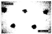
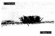
なお、図2〜7に、粘着剤層の表面に形成されている繊維起毛部の形状に関する写真を示す。図2は、粘着剤層の表面に形成されている繊維起毛部の形状に関する写真を示す図であり、粘着剤層の上面から見た図である。図3は、粘着剤層の表面に形成されている繊維起毛部の形状に関する写真を示す図であり、図2に係る繊維起毛部を示す要部拡大図である。また、図4は、粘着剤層の表面に形成されている繊維起毛部の形状に関する写真を示す図であり、粘着剤層の上面から見た図である。図5は、粘着剤層の表面に形成されている繊維起毛部の形状に関する写真を示す図であり、図4に係る繊維起毛部を示す要部拡大図である。さらにまた、図6は、粘着剤層の表面に形成されている繊維起毛部の形状に関する写真を示す図であり、粘着剤層の上面から見た図である。図7は、粘着剤層の表面に形成されている繊維起毛部の形状に関する写真を示す図であり、図6に係る繊維起毛部を示す要部拡大図である。 2 to 7 show photographs of the shape of the fiber raised portion formed on the surface of the pressure-sensitive adhesive layer. FIG. 2 is a view showing a photograph related to the shape of the fiber raised portion formed on the surface of the pressure-sensitive adhesive layer, as viewed from the upper surface of the pressure-sensitive adhesive layer. FIG. 3 is a photograph showing a shape of a fiber raised portion formed on the surface of the pressure-sensitive adhesive layer, and is an enlarged view of a main part showing the fiber raised portion according to FIG. 2. FIG. 4 is a view showing a photograph relating to the shape of the fiber raised portion formed on the surface of the pressure-sensitive adhesive layer, as viewed from the top surface of the pressure-sensitive adhesive layer. FIG. 5 is a photograph showing a shape of a fiber raised portion formed on the surface of the pressure-sensitive adhesive layer, and is an enlarged view of a main part showing the fiber raised portion according to FIG. 4. FIG. 6 is a view showing a photograph of the shape of the fiber raised portion formed on the surface of the pressure-sensitive adhesive layer, as viewed from the top surface of the pressure-sensitive adhesive layer. FIG. 7 is a view showing a photograph regarding the shape of the fiber raised portion formed on the surface of the pressure-sensitive adhesive layer, and is an enlarged view of a main part showing the fiber raised portion according to FIG. 6.
なお、図2〜7で示されている写真は、デジタルマイクロスコープとして商品名「VH−6200」(KEYENCE社製)を用い、倍率:50〜175倍の条件で撮影した写真である。 The photographs shown in FIGS. 2 to 7 are photographs taken under the conditions of a magnification of 50 to 175 times using a brand name “VH-6200” (manufactured by KEYENCE) as a digital microscope.
このような繊維起毛部の構造としては、例えば、(1)1本の繊維の一方の端部が粘着剤層表面に接着されて固定され、他方の端部が固定されていない(自由となっている)状態で、粘着剤層表面から繊維が略I字型に起立している構造(図1や図14で示されている構造)、(2)1本の繊維の中央部が粘着剤層表面に接着され、繊維の両端部が固定されていない(自由となっている)状態で、粘着剤層表面から繊維が略V字型に起立している構造、(3)1本の繊維の両端部が粘着剤層表面に接着されて固定され、繊維の中央部が固定されていない(自由となっている)状態で、粘着剤層表面から繊維が逆略U字型に起立している構造の他、粘着剤層表面から繊維が略W字型、略M字型、略N字型、略O字型などの形状で起立している構造、さらには、これらの構造が組み合わされた構造などが挙げられる。繊維起毛部の構造としては、前記(1)の構造(粘着剤層表面から繊維が略I字型に起立している構造)が好適である。もちろん、繊維起毛部は、粘着テープ又はシート用粘着剤層表面から繊維が、I字型などのように直線状に起立した状態であってもよく、ギザギザ状、波線状、ループ状などの形態を有する状態で、全体的に起立した状態であってもよい。 As the structure of such a fiber raising portion, for example, (1) one end of one fiber is adhered and fixed to the surface of the pressure-sensitive adhesive layer, and the other end is not fixed (free). 1), a structure in which the fibers stand in a substantially I-shape from the surface of the pressure-sensitive adhesive layer (the structure shown in FIGS. 1 and 14), and (2) the center of one fiber is the pressure-sensitive adhesive. A structure in which the fibers stand up in a substantially V-shape from the surface of the pressure-sensitive adhesive layer in a state where the fibers are adhered to the layer surface and both ends of the fibers are not fixed (free), (3) one fiber In the state where both ends of the fiber are adhered and fixed to the surface of the pressure-sensitive adhesive layer, and the central part of the fiber is not fixed (free), the fiber stands upright in a substantially U-shape from the surface of the pressure-sensitive adhesive layer. In addition to the above structure, the fibers stand up from the surface of the pressure-sensitive adhesive layer in a shape such as a substantially W shape, a substantially M shape, a substantially N shape, and a substantially O shape. News, etc. These structures are combined structure. As the structure of the fiber raised portion, the structure of the above (1) (a structure in which the fibers stand in a substantially I-shape from the surface of the pressure-sensitive adhesive layer) is preferable. Needless to say, the fiber raised portion may be in a state where the fibers are linearly erected from the surface of the pressure-sensitive adhesive layer for the pressure-sensitive adhesive tape or sheet, such as an I-shape, and are formed in a jagged shape, a wavy shape, a loop shape, or the like. May be in a state of standing up as a whole.
繊維凸状構造部は、粘着剤層の表面に部分的に設けられている。このように、粘着剤層の表面に部分的に設けられている繊維凸状構造部において、その全体としての形状としては、特に制限されず、目的とするリワーク性や貼付位置修正作業性、被着体の種類などに応じて適宜選択することができ、所定のパターン形状を有していてもよい。 The fiber convex structure is partially provided on the surface of the pressure-sensitive adhesive layer. As described above, the overall shape of the fiber convex structure partly provided on the surface of the pressure-sensitive adhesive layer is not particularly limited, and the intended reworking property, sticking position correcting workability, and coating property can be improved. It can be appropriately selected according to the type of the body to be worn, and may have a predetermined pattern shape.
例えば、繊維凸状構造部が、全体として、図1や図14で示されるようなパターン形状で形成されている場合、すなわち、繊維凸状構造部が、全体として、複数のラインを形成するような形状で設けられている場合、各ラインの間隔は、例えば、1〜100mm(好ましくは3〜50mm、さらに好ましくは5〜40mm)程度の範囲から選択することができる。また、1つのライン内に含まれる各繊維凸状構造部間の間隔は、例えば、1〜100mm(好ましくは3〜50mm、さらに好ましくは5〜40mm)程度の範囲から選択することができる。さらにまた、隣り合ったラインにおける各繊維凸状構造部の位置関係は、特に制限されず、全体として格子状となる位置関係であってもよく、全体として不定形状となる位置関係であってもよい。 For example, when the fiber convex structure is formed as a whole in a pattern shape as shown in FIGS. 1 and 14, that is, the fiber convex structure forms a plurality of lines as a whole. When the lines are provided in various shapes, the spacing between the lines can be selected, for example, from a range of about 1 to 100 mm (preferably 3 to 50 mm, more preferably 5 to 40 mm). In addition, the interval between the fiber convex structures included in one line can be selected, for example, from a range of about 1 to 100 mm (preferably 3 to 50 mm, more preferably 5 to 40 mm). Furthermore, the positional relationship of each fiber convex structure portion in the adjacent line is not particularly limited, and may be a positional relationship of a lattice as a whole or a positional relationship of an irregular shape as a whole. Good.
なお、1つの繊維凸状構造部について、粘着剤層表面における形状としては、特に制限されず、例えば、略円形状や略多角形状であってもよく、不定形状であってもよい。また、粘着剤層の表面に形成されている繊維凸状構造部の数は、特に制限されない。 The shape of one fiber convex structure on the surface of the pressure-sensitive adhesive layer is not particularly limited, and may be, for example, a substantially circular shape, a substantially polygonal shape, or an irregular shape. In addition, the number of fiber convex structures formed on the surface of the pressure-sensitive adhesive layer is not particularly limited.
粘着剤層表面において、繊維凸状構造部が設けられている部位の全面積(全繊維凸状構造部の面積)としては、特に制限されず、例えば、粘着剤層の全表面積に対して0.001〜20%(好ましくは0.005〜15%、さらに好ましくは0.01〜10%)の割合となる面積であることが望ましい。全繊維凸状構造部の粘着剤層表面における面積が、粘着剤層の全表面積に対して0.001%未満であると、初期接着力の低減効果が低下し、リワーク性や貼付位置修正作業性が低下する。一方、全繊維凸状構造部の粘着剤層表面における面積が、粘着剤層の全表面積に対して20%を越えると、リワーク性や貼付位置修正作業性は向上するが、粘着テープ又はシートの被着体への接着力が低下する。 On the surface of the pressure-sensitive adhesive layer, the total area of the portion where the fiber convex structure is provided (the area of the entire fiber convex structure) is not particularly limited. The area is desirably 0.001 to 20% (preferably 0.005 to 15%, more preferably 0.01 to 10%). When the area of the entire fiber convex structure on the surface of the pressure-sensitive adhesive layer is less than 0.001% of the total surface area of the pressure-sensitive adhesive layer, the effect of reducing the initial adhesive force is reduced, and the reworkability and the position of the applied position are corrected. Is reduced. On the other hand, when the area of the entire fiber convex structure portion on the surface of the pressure-sensitive adhesive layer exceeds 20% of the total surface area of the pressure-sensitive adhesive layer, the reworking property and the workability of correcting the sticking position are improved, but the pressure-sensitive adhesive tape or sheet has Adhesion to the adherend decreases.
また、各繊維凸状構造部の面積としては、特に制限されず、例えば、0.1〜10mm2(好ましくは0.3〜5mm2、さらに好ましくは0.5〜3mm2)程度の範囲から選択することが好ましいが、0.1mm2未満であってもよく、10mm2を越えていてもよい。 The area of each fiber convex structure is not particularly limited, and may be, for example, in the range of about 0.1 to 10 mm 2 (preferably 0.3 to 5 mm 2 , more preferably 0.5 to 3 mm 2 ). It is preferable to select, but it may be less than 0.1 mm 2 or more than 10 mm 2 .
さらにまた、例えば、各繊維凸状構造部の面積が0.1〜10mm2であるように、繊維凸状構造部が複数設けられている場合、各繊維凸状構造部間の最短の間隔としては、例えば、1〜100mm(好ましくは3〜50mm、さらに好ましくは5〜40mm)程度であってもよい。 Furthermore, for example, when a plurality of fiber convex structures are provided such that the area of each fiber convex structure is 0.1 to 10 mm 2 , the shortest distance between the fiber convex structures is May be, for example, about 1 to 100 mm (preferably 3 to 50 mm, more preferably 5 to 40 mm).
このような繊維凸状構造部を構成する繊維としては、特に制限されず、天然繊維、半合成繊維、合成繊維のいずれであってもよい。より具体的には、繊維としては、例えば、綿繊維、レーヨン繊維、ポリアミド系繊維[脂肪族ポリアミド繊維、芳香族ポリアミド繊維(いわゆるアラミド繊維)など]、ポリエステル系繊維(商品名「テトロン」など)、ポリアクリロニトリル系繊維、炭素繊維(炭素系繊維)、アクリル系繊維、ポリビニルアルコール繊維(いわゆるビニロン繊維)、ポリエチレン系繊維、ポリイミド系繊維、ポリオレフィン系繊維、シリコーン系繊維、フッ素系繊維(フッ素系樹脂繊維)などが挙げられる。繊維としては、綿繊維、レーヨン繊維、ポリアミド系繊維、ポリエステル系繊維が好適である。 The fibers constituting such a fiber convex structure are not particularly limited, and may be any of natural fibers, semi-synthetic fibers, and synthetic fibers. More specifically, the fibers include, for example, cotton fibers, rayon fibers, polyamide fibers [aliphatic polyamide fibers, aromatic polyamide fibers (so-called aramid fibers) and the like], and polyester fibers (trade name “Tetron”). , Polyacrylonitrile fiber, carbon fiber (carbon fiber), acrylic fiber, polyvinyl alcohol fiber (so-called vinylon fiber), polyethylene fiber, polyimide fiber, polyolefin fiber, silicone fiber, fluorine fiber (fluorine resin) Fiber). As the fibers, cotton fibers, rayon fibers, polyamide fibers, and polyester fibers are suitable.
繊維は、1種のみが用いられていてもよく、2種以上が組み合わせられて用いられていてもよい。 As the fiber, only one kind may be used, or two or more kinds may be used in combination.
このような繊維としては、短繊維を好適に用いることができる。繊維の長さが長くなると、粘着テープ又はシートの被着体への接着力が低下するため好ましくない。繊維としては、その長さが0.1〜5mm(好ましくは0.3〜5mm、さらに好ましくは0.3〜2mm)程度であることが望ましい。なお、繊維の長さが短すぎると、粘着剤層を被着体に接着させる際にかける圧力が低くてもよくなるので、これによりリワーク性や貼付位置修正作業性が低下するため好ましくない。また、繊維の長さが短すぎると、製造が難しく、高価になるため、コスト的な観点からも好ましくない。 Short fibers can be suitably used as such fibers. If the length of the fiber is long, the adhesive force of the pressure-sensitive adhesive tape or sheet to the adherend decreases, which is not preferable. It is desirable that the fiber has a length of about 0.1 to 5 mm (preferably 0.3 to 5 mm, more preferably 0.3 to 2 mm). If the length of the fiber is too short, the pressure to be applied when the pressure-sensitive adhesive layer is adhered to the adherend may be low. On the other hand, if the length of the fiber is too short, the production becomes difficult and the fiber becomes expensive, which is not preferable from the viewpoint of cost.
また、繊維の太さとしては、特に制限されないが、例えば、0.1〜20デニール(好ましくは0.5〜15デニール、さらに好ましくは1〜6デニール)程度の範囲から選択することができる。繊維の太さが太すぎると、柔軟性の低下により、粘着剤層を被着体に接着させる際にかける圧力が高くなるので好ましくない。一方、繊維の太さが細すぎると、初期接着力の低減効果が低下し、リワーク性や貼付位置修正作業性が低下する。 The thickness of the fiber is not particularly limited, but can be selected, for example, from a range of about 0.1 to 20 denier (preferably 0.5 to 15 denier, more preferably 1 to 6 denier). When the thickness of the fiber is too large, the pressure applied when the pressure-sensitive adhesive layer is adhered to the adherend increases due to the decrease in flexibility, which is not preferable. On the other hand, when the thickness of the fiber is too small, the effect of reducing the initial adhesive force is reduced, and the reworkability and the workability of correcting the applied position are reduced.
繊維凸状構造部(特に、繊維起毛部)を形成する方法としては、特に制限されないが、下記に示されるように、植毛加工方法(特に、静電植毛加工方法)を好適に利用することができる。前記静電植毛加工方法としては、アップ法、ダウン法、サイド法のいずれであってもよい。なお、植毛加工方法により粘着剤層の表面の所定の部位に繊維凸状構造部を形成させる際には、粘着剤層の表面における繊維凸状構造部を形成する所定の部位に対応した位置に孔部を有している剥離基材(特に剥離フィルム)を用いることが好ましい。 The method for forming the fiber convex structure portion (particularly, the fiber raised portion) is not particularly limited, but as shown below, it is preferable to use a flocking method (particularly, an electrostatic flocking method). it can. The electrostatic flocking method may be any of an up method, a down method, and a side method. When forming the fiber convex structure portion on a predetermined portion of the surface of the pressure-sensitive adhesive layer by a flocking process, the fiber convex structure portion is formed on the surface of the pressure-sensitive adhesive layer at a position corresponding to the predetermined portion forming the fiber convex structure portion. It is preferable to use a release substrate having a hole (particularly, a release film).
(粘着剤層)
粘着剤層を構成する粘着剤としては、特に制限されず、例えば、ゴム系粘着剤、アクリル系粘着剤、ポリエステル系粘着剤、ウレタン系粘着剤、ポリアミド系粘着剤、エポキシ系粘着剤、ビニルアルキルエーテル系粘着剤、シリコーン系粘着剤、フッ素系粘着剤などの公知の粘着剤を用いることができる。また、粘着剤は、ホットメルト型粘着剤であってもよい。粘着剤は、単独で又は2種以上組み合わせて使用することができる。粘着剤は、エマルジョン系粘着剤、溶剤系粘着剤、オリゴマー系粘着剤、固系粘着剤などのいずれの形態の粘着剤であってもよい。
(Adhesive layer)
The pressure-sensitive adhesive constituting the pressure-sensitive adhesive layer is not particularly limited, and examples thereof include a rubber-based pressure-sensitive adhesive, an acrylic pressure-sensitive adhesive, a polyester-based pressure-sensitive adhesive, a urethane-based pressure-sensitive adhesive, a polyamide-based pressure-sensitive adhesive, an epoxy-based pressure-sensitive adhesive, and a vinylalkyl. Known adhesives such as an ether-based adhesive, a silicone-based adhesive, and a fluorine-based adhesive can be used. The pressure-sensitive adhesive may be a hot-melt pressure-sensitive adhesive. The pressure-sensitive adhesives can be used alone or in combination of two or more. The pressure-sensitive adhesive may be any form of pressure-sensitive adhesive such as an emulsion pressure-sensitive adhesive, a solvent pressure-sensitive adhesive, an oligomer pressure-sensitive adhesive, and a solid pressure-sensitive adhesive.
なお、粘着剤は、粘着性成分(ベースポリマー)等のポリマー成分の他に、粘着剤の種類等に応じて、架橋剤(例えば、ポリイソシアネート系架橋剤、アルキルエーテル化メラミン化合物系架橋剤など)、粘着付与剤(例えば、ロジン誘導体樹脂、ポリテルペン樹脂、石油樹脂、フェノール樹脂など)、可塑剤、充填剤、老化防止剤などの適宜な添加剤を含んでいてもよい。粘着剤層を形成する際に粘着剤を架橋する場合は、加熱による加熱架橋方法、紫外線照射による紫外線架橋方法(UV架橋方法)、電子線照射による電子線架橋方法(EB架橋方法)、室温等で自然に硬化させる自然硬化方法のいずれであってもよい。 The pressure-sensitive adhesive may be a cross-linking agent (for example, a polyisocyanate-based cross-linking agent, an alkyl etherified melamine compound-based cross-linking agent, or the like) depending on the type of the pressure-sensitive adhesive, in addition to the polymer component such as the pressure-sensitive adhesive component (base polymer). ), A tackifier (for example, a rosin derivative resin, a polyterpene resin, a petroleum resin, and a phenol resin), a plasticizer, a filler, and an appropriate additive such as an antioxidant. When the pressure-sensitive adhesive is cross-linked when forming the pressure-sensitive adhesive layer, a heat cross-linking method by heating, an ultraviolet cross-linking method by UV irradiation (UV cross-linking method), an electron beam cross-linking method by electron beam irradiation (EB cross-linking method), room temperature, etc. Any of the natural curing methods of curing naturally.
粘着剤としては、天然ゴムや各種の合成ゴム(例えば、ポリイソプレンゴム、スチレン・ブタジエンゴム、スチレン・イソプレン・スチレンブロック共重合体ゴム、スチレン・ブタジエン・スチレンブロック共重合体ゴム、再生ゴム、ブチルゴム、ポリイソブチレンなど)をベースポリマーとしたゴム系粘着剤;(メタ)アクリル酸アルキルエステルの1種又は2種以上を単量体成分として用いたアクリル系重合体(単独重合体又は共重合体)をベースポリマーとするアクリル系粘着剤を好適に用いることができる。 Examples of the adhesive include natural rubber and various synthetic rubbers (for example, polyisoprene rubber, styrene / butadiene rubber, styrene / isoprene / styrene block copolymer rubber, styrene / butadiene / styrene block copolymer rubber, recycled rubber, butyl rubber , Polyisobutylene, etc.) as a base polymer; an acrylic polymer (homopolymer or copolymer) using one or more alkyl (meth) acrylates as a monomer component An acrylic pressure-sensitive adhesive having a base polymer as the base polymer can be suitably used.
なお、前記アクリル系粘着剤における(メタ)アクリル酸アルキルエステルとしては、例えば、(メタ)アクリル酸メチル、(メタ)アクリル酸エチル、(メタ)アクリル酸プロピル、(メタ)アクリル酸イソプロピル、(メタ)アクリル酸ブチル、(メタ)アクリル酸イソブチル、(メタ)アクリル酸s−ブチル、(メタ)アクリル酸t−ブチル、(メタ)アクリル酸ペンチル、(メタ)アクリル酸ヘキシル、(メタ)アクリル酸ヘプチル、(メタ)アクリル酸オクチル、(メタ)アクリル酸2−エチルヘキシル、(メタ)アクリル酸イソオクチル、(メタ)アクリル酸ノニル、(メタ)アクリル酸イソノニル、(メタ)アクリル酸デシル、(メタ)アクリル酸イソデシル、(メタ)アクリル酸ウンデシル、(メタ)アクリル酸ドデシル、(メタ)アクリル酸トリデシル、(メタ)アクリル酸テトラデシル、(メタ)アクリル酸ペンタデシル、(メタ)アクリル酸ヘキサデシル、(メタ)アクリル酸ヘプタデシル、(メタ)アクリル酸オクタデシル、(メタ)アクリル酸ノナデシル、(メタ)アクリル酸エイコシルなどの(メタ)アクリル酸C1-20アルキルエステル[好ましくは(メタ)アクリル酸C4-18アルキル(直鎖状又は分岐鎖状のアルキル)エステル]などが挙げられる。(メタ)アクリル酸アルキルエステルとしては、目的とする粘着性などに応じて適宜選択することができる。(メタ)アクリル酸アルキルエステルは単独で又は2種以上組み合わせて使用することができる。 The alkyl (meth) acrylate in the acrylic pressure-sensitive adhesive includes, for example, methyl (meth) acrylate, ethyl (meth) acrylate, propyl (meth) acrylate, isopropyl (meth) acrylate, and (meth) acrylate. ) Butyl acrylate, isobutyl (meth) acrylate, s-butyl (meth) acrylate, t-butyl (meth) acrylate, pentyl (meth) acrylate, hexyl (meth) acrylate, heptyl (meth) acrylate Octyl (meth) acrylate, 2-ethylhexyl (meth) acrylate, isooctyl (meth) acrylate, nonyl (meth) acrylate, isononyl (meth) acrylate, decyl (meth) acrylate, (meth) acrylic acid Isodecyl, undecyl (meth) acrylate, dodecyl (meth) acrylate, Tridecyl (meth) acrylate, tetradecyl (meth) acrylate, pentadecyl (meth) acrylate, hexadecyl (meth) acrylate, heptadecyl (meth) acrylate, octadecyl (meth) acrylate, nonadecyl (meth) acrylate, (meth) And C 1-20 alkyl (meth) acrylates [preferably C 4-18 alkyl (meth) acrylates (linear or branched alkyl) esters] such as eicosyl acrylate. The alkyl (meth) acrylate can be appropriately selected depending on the desired tackiness and the like. The alkyl (meth) acrylates can be used alone or in combination of two or more.
また、前記アクリル系粘着剤において、(メタ)アクリル酸アルキルエステルとともに、必要に応じて前記(メタ)アクリル酸アルキルエステルと共重合可能な他のモノマー(共重合性モノマー)が併用されていてもよい。このような共重合性モノマーとしては、例えば、(メタ)アクリル酸、イタコン酸、マレイン酸、フマル酸、クロトン酸、イソクロトン酸などのカルボキシル基含有単量体又はその無水物;ビニルスルホン酸ナトリウムなどのスルホン酸基含有単量体;スチレン、置換スチレンなどの芳香族ビニル化合物;アクリロニトリルなどのシアノ基含有単量体;エチレン、プロピレン、ブタジエンなどのオレフィン類;酢酸ビニルなどのビニルエステル類;塩化ビニル;アクリルアミド、メタアクリルアミド、N−ビニルピロリドン、N,N−ジメチル(メタ)アクリルアミドなどのアミド基含有単量体;(メタ)アクリル酸ヒドロキシアルキル、グリセリンジメタクリレートなどの水酸基含有単量体;(メタ)アクリル酸アミノエチル、(メタ)アクリロイルモルホリンなどのアミノ基含有単量体;シクロヘキシルマレイミド、イソプロピルマレイミドなどのイミド基含有単量体;(メタ)アクリル酸グリシジル、(メタ)アクリル酸メチルグリシジルなどのエポキシ基含有単量体;2−メタクリロイルオキシエチルイソシアネートなどのイソシアネート基含有単量体などが挙げられる。また、共重合性単量体としては、例えば、トリエチレングリコールジ(メタ)アクリレート、ジエチレングリコールジ(メタ)アクリレート、エチレングリコールジ(メタ)アクリレート、テトラエチレングリコールジ(メタ)アクリレート、ネオペンチルグリコールジ(メタ)アクリレート、1,6−ヘキサンジオールジ(メタ)アクリレート、トリメチロールプロパントリ(メタ)アクリレート、ペンタエリスリトールトリ(メタ)アクリレート、ジペンタエリスリトールヘキサ(メタ)アクリレート、ジビニルベンゼンなどの多官能性の共重合性単量体(多官能モノマー)などが挙げられる。共重合性モノマーは単独で又は2種以上組み合わせて使用することができる。 Further, in the acrylic pressure-sensitive adhesive, other monomers (copolymerizable monomers) copolymerizable with the alkyl (meth) acrylate may be used in combination with the alkyl (meth) acrylate as necessary. Good. Examples of such a copolymerizable monomer include, for example, a carboxyl group-containing monomer such as (meth) acrylic acid, itaconic acid, maleic acid, fumaric acid, crotonic acid, and isocrotonic acid, or an anhydride thereof; sodium vinyl sulfonate; Aromatic vinyl compounds such as styrene and substituted styrene; Cyano group-containing monomers such as acrylonitrile; olefins such as ethylene, propylene and butadiene; vinyl esters such as vinyl acetate; An amide group-containing monomer such as acrylamide, methacrylamide, N-vinylpyrrolidone, N, N-dimethyl (meth) acrylamide; a hydroxyl group-containing monomer such as hydroxyalkyl (meth) acrylate and glycerin dimethacrylate; ) Aminoethyl acrylate, (meth) a Amino group-containing monomers such as liroyl morpholine; imide group-containing monomers such as cyclohexylmaleimide and isopropylmaleimide; epoxy group-containing monomers such as glycidyl (meth) acrylate and methyl glycidyl (meth) acrylate; -Isocyanate group-containing monomers such as methacryloyloxyethyl isocyanate. Examples of the copolymerizable monomer include triethylene glycol di (meth) acrylate, diethylene glycol di (meth) acrylate, ethylene glycol di (meth) acrylate, tetraethylene glycol di (meth) acrylate, and neopentyl glycol diene. Multifunctionality such as (meth) acrylate, 1,6-hexanediol di (meth) acrylate, trimethylolpropane tri (meth) acrylate, pentaerythritol tri (meth) acrylate, dipentaerythritol hexa (meth) acrylate, divinylbenzene (Polyfunctional monomers). The copolymerizable monomers can be used alone or in combination of two or more.
粘着剤層の形成方法としては、公知乃至慣用の形成方法を採用することができ、例えば、粘着テープ又はシート用基材を有している基材付き粘着テープ又はシートの場合、支持体としての基材(粘着テープ又はシート用基材)上に、粘着剤を塗布する方法(塗布方法)、剥離ライナーなどの剥離フィルム上に、粘着剤を塗布して粘着剤層を形成した後、該粘着剤層を基材上に転写する方法(転写方法)などが挙げられる。また、粘着テープ又はシート用基材を有していない基材レス粘着テープ又はシートの場合、粘着剤層の形成方法としては、支持体としての剥離ライナーの剥離面上に、粘着剤を塗布する方法(塗布方法)などが挙げられる。 As a method for forming the pressure-sensitive adhesive layer, a known or commonly used forming method can be employed.For example, in the case of a pressure-sensitive adhesive tape or sheet having a substrate having a pressure-sensitive adhesive tape or sheet substrate, a support A method of applying an adhesive on a base material (an adhesive tape or a base material for a sheet) (application method), and forming an adhesive layer by applying an adhesive on a release film such as a release liner. A method of transferring the agent layer onto the base material (transfer method) is exemplified. In the case of a substrate-less pressure-sensitive adhesive tape or sheet having no pressure-sensitive adhesive tape or sheet substrate, a method for forming a pressure-sensitive adhesive layer includes applying a pressure-sensitive adhesive on a release surface of a release liner as a support. Method (application method) and the like.
粘着剤層の厚さとしては、特に制限されず、例えば、1〜1000μm(好ましくは10〜500μm)程度の範囲から選択することができる。 The thickness of the pressure-sensitive adhesive layer is not particularly limited, and can be selected, for example, from a range of about 1 to 1000 μm (preferably 10 to 500 μm).
(支持体)
粘着剤層を支持する支持体としては、粘着テープ又はシートが、基材付きタイプの片面又は両面が粘着剤層となっている粘着テープ又はシートの場合、基材(粘着テープ又はシート用基材)を用いることができ、一方、基材レスタイプの両面粘着テープ又はシートの場合、剥離ライナー(セパレータ)を用いることができる。なお、粘着テープ又はシートが、基材付きタイプの片面又は両面が粘着剤層となっている粘着テープ又はシートの場合、支持体としての基材の片面又は両面に粘着剤層が形成されているとともに、基材の片面又は両面に形成された粘着剤層の表面に部分的に繊維凸状構造部が形成されており、粘着剤層の表面は、基材の背面側の剥離面や、剥離ライナーにより保護されていてもよい。一方、粘着テープ又はシートが、基材レスタイプの両面粘着テープ又はシートの場合、剥離ライナーが粘着剤層の支持体となっているとともに、粘着剤層の片方又は両方の表面に部分的に繊維凸状構造部が形成されている。なお、支持体としての剥離ライナーは、粘着テープ又はシートを使用するまでの間、粘着剤層を支持しているとともに、粘着剤層の表面を保護している。
(Support)
As a support for supporting the pressure-sensitive adhesive layer, when the pressure-sensitive adhesive tape or sheet is a pressure-sensitive adhesive tape or sheet of a substrate-attached type having one or both sides formed of a pressure-sensitive adhesive layer, the base material (substrate for pressure-sensitive adhesive tape or sheet) On the other hand, in the case of a double-sided pressure-sensitive adhesive tape or sheet of a substrate-less type, a release liner (separator) can be used. In the case where the pressure-sensitive adhesive tape or sheet is a pressure-sensitive adhesive tape or sheet having one or both sides of a substrate-attached type and a pressure-sensitive adhesive layer, a pressure-sensitive adhesive layer is formed on one or both sides of a substrate as a support. At the same time, a fiber convex structure portion is formed partially on the surface of the pressure-sensitive adhesive layer formed on one or both surfaces of the base material, and the surface of the pressure-sensitive adhesive layer has a release surface on the back side of the base material or a release surface. It may be protected by a liner. On the other hand, when the pressure-sensitive adhesive tape or sheet is a substrate-less type double-sided pressure-sensitive adhesive tape or sheet, the release liner serves as a support for the pressure-sensitive adhesive layer, and a fiber partially covers one or both surfaces of the pressure-sensitive adhesive layer. A convex structure is formed. The release liner as a support supports the pressure-sensitive adhesive layer and protects the surface of the pressure-sensitive adhesive layer until the pressure-sensitive adhesive tape or sheet is used.
(基材)
前記基材(粘着テープ又はシート用基材)としては、例えば、プラスチックのフィルムやシートなどのプラスチック系基材;金属箔、金属板などの金属系基材;紙(上質紙、和紙、クラフト紙、グラシン紙、合成紙、トップコート紙等)などの紙系基材;布、不織布、ネットなどの繊維系基材;ゴムシートなどのゴム系基材;発泡シートなどの発泡体等の適宜な薄葉体を用いることができる。基材は、単層の形態を有していてもよく、積層された形態を有していてもよい。例えば、基材としては、ラミネートや共押し出しなどにより、プラスチック系基材と他の基材(紙系基材など)とを複層化したもの(2〜3層の複合体)などであってもよい。
(Base material)
Examples of the base material (adhesive tape or sheet base material) include, for example, plastic base materials such as plastic films and sheets; metal base materials such as metal foils and metal plates; paper (fine wood, Japanese paper, kraft paper). , Glassine paper, synthetic paper, top coated paper, etc.); fibrous base material such as cloth, nonwoven fabric, net, etc .; rubber base material such as rubber sheet; Thin leaflets can be used. The substrate may have a single-layer form or a laminated form. For example, as the base material, a plastic base material and another base material (such as a paper base material) formed by lamination or co-extrusion into a multi-layer structure (composite of two to three layers), and the like may be used. Is also good.
基材としては、プラスチックのフィルムやシートが好ましい。このようなプラスチックのフィルムやシートの素材(プラスチック材)としては、例えば、ポリエチレン(PE)、ポリプロピレン(PP)、エチレン−プロピレン共重合体、エチレン−酢酸ビニル共重合体(EVA)等のα−オレフィンをモノマー成分とするオレフィン系樹脂;ポリエチレンテレフタレート(PET)、ポリエチレンナフタレート(PEN)、ポリブチレンテレフタレート(PBT)等のポリエステル系樹脂;ポリ塩化ビニル(PVC);酢酸ビニル系樹脂;ポリフェニレンスルフィド(PPS);ポリアミド(ナイロン)、全芳香族ポリアミド(アラミド)等のアミド系樹脂;ポリイミド系樹脂;ポリエーテルエーテルケトン(PEEK)などが挙げられる。プラスチック材は単独で用いられていてもよく、2種以上組み合わせられた混合状態で用いられていてもよい。なお、プラスチックのフィルムやシートは、無延伸タイプであってもよく、1軸または2軸の延伸処理が施された延伸タイプであってもよい。 As the substrate, a plastic film or sheet is preferable. As a material (plastic material) for such a plastic film or sheet, for example, α- such as polyethylene (PE), polypropylene (PP), ethylene-propylene copolymer, ethylene-vinyl acetate copolymer (EVA), etc. An olefin resin containing an olefin as a monomer component; a polyester resin such as polyethylene terephthalate (PET), polyethylene naphthalate (PEN), or polybutylene terephthalate (PBT); polyvinyl chloride (PVC); a vinyl acetate resin; polyphenylene sulfide ( Amide resins such as polyamide (nylon) and wholly aromatic polyamide (aramid); polyimide resins; polyetheretherketone (PEEK). The plastic materials may be used alone or in a mixture of two or more. The plastic film or sheet may be a non-stretched type or a stretched type subjected to uniaxial or biaxial stretching.
なお、基材には、必要に応じて、無機質充填剤(例えば、酸化チタン、酸化亜鉛など)、老化防止剤(例えば、アミン系老化防止剤、キノリン系老化防止剤、ヒドロキノン系老化防止剤、フェノール系老化防止剤、リン系老化防止剤、亜リン酸エステル系老化防止剤など)、酸化防止剤、紫外線吸収剤(例えば、サリチル酸誘導体、ベンゾフェノン系紫外線吸収剤、ベンゾトリアゾール系紫外線吸収剤、ヒンダードアミン系紫外線吸収剤など)、滑剤、可塑剤、着色剤(例えば、顔料、染料など)等の各種添加剤が配合されていてもよい。 In addition, if necessary, an inorganic filler (for example, titanium oxide, zinc oxide, etc.), an antioxidant (for example, an amine antioxidant, a quinoline antioxidant, a hydroquinone antioxidant, Phenolic antioxidants, phosphorus antioxidants, phosphite antioxidants, etc.), antioxidants, ultraviolet absorbers (for example, salicylic acid derivatives, benzophenone ultraviolet absorbers, benzotriazole ultraviolet absorbers, hindered amines) And various additives such as a lubricant, a plasticizer, and a colorant (for example, a pigment and a dye).
基材の片面または両面には、粘着剤層との密着力の向上等を目的に、コロナ処理やプラズマ処理等の物理的処理、下塗り剤等の化学的処理などの適宜な表面処理が施されていてもよい。 On one or both sides of the base material, an appropriate surface treatment such as a corona treatment or a physical treatment such as a plasma treatment or a chemical treatment such as a primer is applied for the purpose of improving the adhesion to the pressure-sensitive adhesive layer. May be.
基材の厚さとしては、例えば、10〜300μm、好ましくは30〜200μm程度の範囲から選択することができる。 The thickness of the substrate can be selected, for example, from a range of about 10 to 300 μm, preferably about 30 to 200 μm.
(剥離ライナー)
前記剥離ライナーとしては、例えば、剥離処理剤による剥離処理層を少なくとも一方の表面に有する基材の他、フッ素系ポリマー(例えば、ポリテトラフルオロエチレン、ポリクロロトリフルオロエチレン、ポリフッ化ビニル、ポリフッ化ビニリデン、テトラフルオロエチレン・ヘキサフルオロプロピレン共重合体、クロロフルオロエチレン・フッ化ビニリデン共重合体等)からなる低接着性基材や、無極性ポリマー(例えば、ポリエチレン、ポリプロピレン等のオレフィン系樹脂など)からなる低接着性基材などを用いることができる。
(Release liner)
As the release liner, for example, in addition to a substrate having a release treatment layer with a release treatment agent on at least one surface, a fluorine-based polymer (for example, polytetrafluoroethylene, polychlorotrifluoroethylene, polyvinyl fluoride, polyfluoride) Low-adhesive base materials composed of vinylidene, tetrafluoroethylene / hexafluoropropylene copolymer, chlorofluoroethylene / vinylidene fluoride copolymer, etc., and non-polar polymers (eg, olefinic resins such as polyethylene and polypropylene) For example, a low-adhesion substrate made of
剥離ライナーとしては、例えば、剥離ライナー用基材の少なくとも一方の面に剥離処理層が形成されている剥離ライナーを好適に用いることができる。このような剥離ライナー用基材としては、ポリエステルフィルム(ポリエチレンテレフタレートフィルム等)、オレフィン系樹脂フィルム(ポリエチレンフィルム、ポリプロピレンフィルム等)、ポリ塩化ビニルフィルム、ポリイミドフィルム、ポリアミドフィルム(ナイロンフィルム)などのプラスチック系基材フィルム(合成樹脂フィルム)や、紙類(上質紙、和紙、クラフト紙、グラシン紙、合成紙、トップコート紙など)の他、これらを、ラミネートや共押し出しなどにより、複層化したもの(2〜3層の複合体)などが挙げられる。 As the release liner, for example, a release liner having a release treatment layer formed on at least one surface of a release liner substrate can be suitably used. Examples of such a release liner substrate include plastics such as polyester film (polyethylene terephthalate film, etc.), olefin resin film (polyethylene film, polypropylene film, etc.), polyvinyl chloride film, polyimide film, polyamide film (nylon film). In addition to system base film (synthetic resin film) and papers (high quality paper, Japanese paper, kraft paper, glassine paper, synthetic paper, top coated paper, etc.), these were made into multiple layers by lamination and co-extrusion. (Composite of 2 to 3 layers) and the like.
一方、剥離処理層を構成する剥離処理剤としては、特に制限されず、例えば、シリコーン系剥離処理剤、フッ素系剥離処理剤、長鎖アルキル系剥離処理剤などを用いることができる。剥離処理剤は単独で又は2種以上組み合わせて使用することができる。 On the other hand, the release treatment agent constituting the release treatment layer is not particularly limited, and for example, a silicone-based release treatment agent, a fluorine-based release treatment agent, a long-chain alkyl-based release treatment agent, or the like can be used. The release agents can be used alone or in combination of two or more.
剥離処理剤としては、剥離性やコストなどの観点より、シリコーン系剥離処理剤が好適である。シリコーン系剥離処理剤は、ポリシロキサン系ポリマーを主成分とする公知のポリシロキサン系剥離処理剤(シリコーン系剥離処理剤)から適宜選択して用いることができる。シリコーン系剥離処理剤としては、なかでも、付加反応型のポリシロキサン系剥離処理剤を好適に用いることができる。付加反応型のポリシロキサン系剥離処理剤は、付加反応型の架橋(硬化反応)により硬化して剥離性被膜を形成し、有用な剥離特性を発現することができる。 As the release treatment agent, a silicone-based release treatment agent is preferable from the viewpoints of releasability, cost, and the like. The silicone-based release treatment agent can be appropriately selected from known polysiloxane-based release treatment agents containing a polysiloxane-based polymer as a main component (silicone-based release treatment agent). As the silicone-based release agent, an addition-reaction-type polysiloxane-based release agent can be suitably used. The addition-reaction-type polysiloxane-based release treatment agent can be cured by addition-reaction-type crosslinking (curing reaction) to form a releasable film and exhibit useful release characteristics.
付加反応型のポリシロキサン系剥離処理剤は、分子中に、Si−H結合を有する基に対して反応性を有する基(具体的には、ビニル基やヘキセニル基等のアルケニル基が含まれる。;以下、「Si−H結合を有する基に対して反応性を有する基」のことを、単に「アルケニル基」と称する場合がある)を2個以上有しているポリシロキサン系ポリマーと、分子中にケイ素原子に結合している水素原子を2個以上有しているポリシロキサン系ポリマー(特に、分子中にSi−H結合を有するケイ素原子を2個以上有しているポリシロキサン系ポリマー)とを含有するポリシロキサン系剥離処理剤組成物を用いることができる。なお、「Si−H結合」とは、「ケイ素原子(Si)と水素原子(H)との結合」を意味している。 The addition-reaction-type polysiloxane-based release agent contains, in the molecule, a group reactive with a group having a Si—H bond (specifically, an alkenyl group such as a vinyl group or a hexenyl group). A polysiloxane-based polymer having two or more “groups having reactivity to a group having a Si—H bond” may be simply referred to as “alkenyl group”); Polysiloxane-based polymer having two or more silicon-bonded hydrogen atoms (particularly, polysiloxane-based polymer having two or more silicon atoms having a Si-H bond in the molecule) And a polysiloxane-based release agent composition containing: The “Si—H bond” means “bond between a silicon atom (Si) and a hydrogen atom (H)”.
また、アルケニル基を2個以上有しているポリシロキサン系ポリマーにおいて、主鎖又は骨格を形成しているポリシロキサン系ポリマーとしては、例えば、ポリジメチルシロキサン系ポリマー、ポリジエチルシロキサン系ポリマー、ポリメチルエチルシロキサン系ポリマー等のポリアルキルアルキルシロキサン系ポリマーや、ポリアルキルアリールシロキサン系ポリマーの他、ケイ素原子含有モノマー成分が複数種用いられている共重合体[例えば、ポリ(ジメチルシロキサン−ジエチルシロキサン)など]などが挙げられ、ポリジメチルシロキサン系ポリマーが好適である。 In the polysiloxane polymer having two or more alkenyl groups, examples of the polysiloxane polymer having a main chain or a skeleton include a polydimethylsiloxane polymer, a polydiethylsiloxane polymer, and a polymethylsiloxane. In addition to polyalkylalkylsiloxane-based polymers such as ethylsiloxane-based polymers, polyalkylarylsiloxane-based polymers, and copolymers using a plurality of silicon atom-containing monomer components [for example, poly (dimethylsiloxane-diethylsiloxane) and the like] And the like, and a polydimethylsiloxane-based polymer is preferable.
一方、分子中にSi−H結合を有するケイ素原子を2個以上有しているポリシロキサン系ポリマーにおいて、Si−H結合を有するケイ素原子としては、主鎖中のケイ素原子、側鎖中のケイ素原子のいずれであってもよく、すなわち、主鎖の構成単位として含まれていてもよく、あるいは、側鎖の構成単位として含まれていてもよい。なお、Si−H結合のケイ素原子(水素原子が結合しているケイ素原子)の数は、2個以上であれば特に制限されない。 On the other hand, in a polysiloxane polymer having two or more silicon atoms having a Si—H bond in a molecule, the silicon atom having a Si—H bond includes a silicon atom in a main chain and a silicon atom in a side chain. It may be any atom, that is, it may be contained as a constituent unit of the main chain, or may be contained as a constituent unit of a side chain. The number of Si-H bonded silicon atoms (silicon atoms to which hydrogen atoms are bonded) is not particularly limited as long as it is two or more.
分子中にSi−H結合を有するケイ素原子を2個以上有しているポリシロキサン系ポリマーとしては、分子中にモノマー単位として「−Si(R)(H)O−」(Rは炭化水素基)を少なくとも2個有しているポリシロキサン系ポリマーが好ましく、なかでも、ポリジメチルハイドロジェンシロキサン系ポリマー[例えば、ポリ(ジメチルシロキサン−メチルシロキサン)等]が好適である。 As a polysiloxane-based polymer having two or more silicon atoms having a Si—H bond in a molecule, “—Si (R) (H) O—” (R is a hydrocarbon group) as a monomer unit in the molecule Is preferable, and a polydimethylhydrogensiloxane-based polymer [for example, poly (dimethylsiloxane-methylsiloxane)] is preferable.
なお、ポリシロキサン系剥離処理剤において、分子中にSi−H結合を有するケイ素原子を2個以上有しているポリシロキサン系ポリマーは、架橋剤としての機能を有している。 In the polysiloxane-based release agent, a polysiloxane-based polymer having two or more silicon atoms having a Si—H bond in a molecule has a function as a crosslinking agent.
分子中にSi−H結合のケイ素原子を2個以上有するポリシロキサン系ポリマーの使用量としては、特に制限されないが、例えば、分子中にSi−H結合のケイ素原子を2個以上有するポリシロキサン系ポリマーにおけるSi−H結合のケイ素原子のモル数(「モル数(X)」と称する場合がある)と、アルケニル基を2個以上有するポリシロキサン系ポリマーにおけるアルケニル基のモル数(「モル数(Y)」と称する場合がある)とが、モル数(X)>モル数(Y)となる割合が好ましいが、モル数(X)/モル数(Y)が0.8〜3.0(好ましくは1.1〜1.8)程度となる割合の範囲から選択してもよい。 The amount of the polysiloxane-based polymer having two or more Si-H-bonded silicon atoms in the molecule is not particularly limited. For example, a polysiloxane-based polymer having two or more Si-H-bonded silicon atoms in the molecule may be used. The number of moles of silicon atoms of the Si—H bond in the polymer (sometimes referred to as “number of moles (X)”) and the number of moles of alkenyl groups in the polysiloxane polymer having two or more alkenyl groups (“number of moles ( Y)) is preferably a ratio in which the number of moles (X)> the number of moles (Y) is satisfied, but the number of moles (X) / the number of moles (Y) is 0.8 to 3.0 ( Preferably, the ratio may be selected from a range of about 1.1 to 1.8).
分子中にアルケニル基を2個以上有しているポリシロキサン系ポリマーを、分子中にSi−H結合を有するケイ素原子を2個以上有しているポリシロキサン系ポリマー(架橋剤)により硬化させる際には、触媒を用いることができ、該触媒としては、白金系触媒(例えば、白金微粒子、塩化白金酸又はその誘導体等の白金系化合物など)を好適に用いることができる。触媒の使用量としては、特に制限されないが、例えば、分子中にアルケニル基を2個以上有するポリシロキサン系ポリマーに対して0.1〜1000ppm(好ましくは1〜100ppm)の範囲から選択することができる。 When curing a polysiloxane polymer having two or more alkenyl groups in the molecule with a polysiloxane polymer (crosslinking agent) having two or more silicon atoms having a Si—H bond in the molecule A platinum-based catalyst (for example, a platinum-based compound such as platinum fine particles, chloroplatinic acid or a derivative thereof) can be suitably used as the catalyst. The amount of the catalyst used is not particularly limited, but may be selected, for example, from the range of 0.1 to 1000 ppm (preferably 1 to 100 ppm) based on the polysiloxane-based polymer having two or more alkenyl groups in the molecule. it can.
本発明では、ポリシロキサン系剥離処理剤としては、分子中にアルケニル基としてビニル基を2個以上有しているポリジメチルシロキサン系ポリマーと、分子中にモノマー単位として「−Si(R)(H)O−」(Rは炭化水素基)を2個以上有しているポリジメチルハイドロジェンシロキサン系ポリマーとによるポリジメチルシロキサン系剥離剤を好適に用いることができる。 In the present invention, as the polysiloxane-based release treatment agent, a polydimethylsiloxane-based polymer having two or more vinyl groups as alkenyl groups in the molecule, and "-Si (R) (H A) A polydimethylsiloxane-based release agent based on a polydimethylhydrogensiloxane-based polymer having two or more “O-” (R is a hydrocarbon group) can be suitably used.
ポリシロキサン系剥離処理剤は、前記構成成分(例えば、分子中にアルケニル基を2個以上有しているポリジメチルシロキサン系ポリマー、分子中にSi−H結合を有するケイ素原子を2個以上有しているポリシロキサン系ポリマー、必要に応じて触媒や各種添加剤など)を、必要に応じて有機溶剤を用いて混合することにより調製することができる。なお、ポリシロキサン系剥離処理剤は、ポリシロキサン系ポリマー等のポリマー成分が有機溶剤に溶解された状態で用いることができる。なお、ポリシロキサン系剥離処理剤には、公知乃至慣用の添加剤(例えば、充填剤、帯電防止剤、酸化防止剤、紫外線吸収剤、可塑剤、着色剤(染料や顔料等)など)が配合されていてもよい。 The polysiloxane-based release treatment agent is a component (for example, a polydimethylsiloxane-based polymer having two or more alkenyl groups in a molecule, and having two or more silicon atoms having a Si—H bond in a molecule) (A polysiloxane-based polymer and, if necessary, a catalyst and various additives, etc.) using an organic solvent, if necessary. The polysiloxane release agent can be used in a state where a polymer component such as a polysiloxane polymer is dissolved in an organic solvent. The polysiloxane-based release agent contains known or commonly used additives (eg, fillers, antistatic agents, antioxidants, ultraviolet absorbers, plasticizers, coloring agents (dyes, pigments, etc.)). It may be.
このようなポリシロキサン系剥離処理剤としては、例えば、商品名「TPR6600」(GE東芝シリコーン社製)、商品名「KS−778」(信越化学社製)、商品名「KS−837」(信越化学社製)などが市販されている。 Examples of such a polysiloxane-based release treatment agent include “TPR6600” (trade name, manufactured by GE Toshiba Silicones), “KS-778” (trade name, manufactured by Shin-Etsu Chemical Co., Ltd.), and “KS-837” (trade name, manufactured by Shin-Etsu Chemical Co., Ltd.) And the like are commercially available.
剥離処理層は、剥離処理剤を剥離ライナー用基材の所定の面(少なくとも一方の面)に塗布した後、乾燥や硬化反応等のための加熱工程を経て形成することができる。なお、乾燥や硬化反応等のための加熱工程では、公知乃至慣用の加熱方法(例えば、熱風式乾燥機を用いる方法など)を利用することができる。なお、付加反応型のポリシロキサン系剥離処理剤は、剥離ライナー用基材の所定の面に塗布した後、乾燥工程又は硬化反応工程などで、付加反応型の硬化反応を行って剥離性皮膜を形成させることにより、優れた剥離特性を発揮させることができる。 The release treatment layer can be formed by applying a release treatment agent to a predetermined surface (at least one surface) of the release liner substrate, and then performing a heating step for drying, curing reaction and the like. In the heating step for the drying or curing reaction, a known or commonly used heating method (for example, a method using a hot air dryer) can be used. The addition-reaction type polysiloxane-based release agent is applied to a predetermined surface of the release liner substrate, and then subjected to an addition-reaction type curing reaction in a drying step or a curing reaction step to form a release film. By forming them, excellent release characteristics can be exhibited.
また、剥離処理剤は、適正な塗布量で塗布することが重要である。剥離処理剤の塗布量が、少なすぎると、剥離力(剥離に要する力)が大きくなって実用上問題が生じ、一方、多すぎると、コストが高くなって経済的に不利になる。剥離処理剤の適正な塗布量(固形分)としては、用いる粘着剤の種類などに応じて適宜選択することができるが、例えば、0.01〜5g/m2(好ましくは0.05〜3g/m2、さらに好ましくは0.2〜1g/m2)程度である。 It is important that the release agent is applied in an appropriate amount. If the amount of the release agent applied is too small, the peeling force (force required for peeling) increases, causing a practical problem. On the other hand, if the amount is too large, the cost increases and it is economically disadvantageous. The appropriate application amount (solid content) of the release treatment agent can be appropriately selected depending on the kind of the pressure-sensitive adhesive to be used, and is, for example, 0.01 to 5 g / m 2 (preferably 0.05 to 3 g). / M 2 , more preferably about 0.2 to 1 g / m 2 ).
なお、剥離ライナーの厚み、剥離ライナー用基材の厚みや、剥離処理層の厚みなどは特に制限されず、繊維凸状構造部の形状などに応じて適宜選択することができる。 The thickness of the release liner, the thickness of the release liner substrate, the thickness of the release treatment layer, and the like are not particularly limited, and can be appropriately selected according to the shape of the fiber convex structure.
特に、剥離ライナーが、粘着剤層の繊維凸状構造部を有する表面を保護するために用いられる場合、剥離ライナーとしては、粘着剤層の表面には繊維凸状構造部が形成されているので、粘着剤層の表面の繊維凸状構造部に対応する部位に凹部(孔部や陥没部など)を有している剥離ライナーを好適に用いることができ、なかでも、図1で示されるような、粘着剤層の表面の繊維凸状構造部に対応する部位に孔部(特に、穿孔部)を有している剥離ライナーが好適である。このような孔部を有する剥離ライナーとしては、繊維凸状構造部の繊維が倒れないように保護するため、少なくとも孔部(特に、穿孔部)の外周領域部の厚みが繊維凸状構造部の高さと同程度またはそれ以上となっていることが好ましい。 In particular, when the release liner is used to protect the surface of the pressure-sensitive adhesive layer having the fiber convex structure, as the release liner, the fiber convex structure is formed on the surface of the pressure-sensitive adhesive layer. A release liner having a concave portion (a hole portion, a depressed portion, or the like) at a portion corresponding to the fiber convex structure portion on the surface of the pressure-sensitive adhesive layer can be suitably used. Among them, as shown in FIG. A release liner having a hole (particularly, a perforated portion) at a portion corresponding to the fiber convex structure on the surface of the pressure-sensitive adhesive layer is preferable. In a release liner having such a hole, at least the thickness of the outer peripheral region of the hole (particularly, the perforated portion) is reduced in order to protect the fibers of the fiber convex structure from falling down. It is preferable that the height is equal to or higher than the height.
剥離ライナーの凹部(特に、孔部)を形成する方法としては、例えば、公知乃至慣用の凹部形成機[なかでも、各種形状の凸部構造(突起状構造)と、該凸部構造に相対する凹部構造とを有する穿孔形成機]を用いる方法、熱や光線による方法(例えば、サーマルヘッド、ハロゲンランプ、キセノンランプ、フラッシュランプ、レーザー光線などにより穿孔する方法)、金型(特に、凸部を有する金型)を用いた成型加工による方法などが挙げられる。 As a method of forming a concave portion (particularly, a hole portion) of the release liner, for example, a known or commonly used concave portion forming machine [among others, a convex portion structure (projection-like structure) of various shapes, and a method corresponding to the convex portion structure] Using a perforation forming machine having a concave structure], a method using heat or light (for example, a method for perforating using a thermal head, a halogen lamp, a xenon lamp, a flash lamp, a laser beam, etc.), a mold (especially having a convex part). Molding) using a mold.
(粘着テープ又はシート)
粘着テープ又はシートとしては、(1)粘着剤層が、支持体としての基材の両面に形成されており、前記基材の少なくとも一方の面の粘着剤層の表面に、部分的に繊維凸状構造部を有している基材付きタイプの両面粘着テープ又はシート、(2)粘着剤層が、支持体としての基材の片面に形成されており、前記粘着剤層の表面に、部分的に繊維凸状構造部を有している基材付きタイプの粘着テープ又はシート(片面粘着テープ又はシート)、(3)粘着剤層が、少なくとも一方の表面に、部分的に繊維凸状構造部を有しており、且つ粘着剤層の両面が1つ又は2つの剥離ライナーで保護されている基材レスタイプの両面粘着テープ又はシートなどを例示できる。
(Adhesive tape or sheet)
As the pressure-sensitive adhesive tape or sheet, (1) a pressure-sensitive adhesive layer is formed on both sides of a base material as a support, and at least one surface of the pressure-sensitive adhesive layer on at least one side of the base material has fiber projections. (2) a pressure-sensitive adhesive layer or a double-sided pressure-sensitive adhesive tape or sheet having a substrate-like structure having a step-like structure portion, wherein (2) a pressure-sensitive adhesive layer is formed on one surface of a substrate as a support, and Pressure-sensitive adhesive tape or sheet with a substrate having a fiber convex structure part (single-sided pressure-sensitive adhesive tape or sheet), and (3) a pressure-sensitive adhesive layer having a fiber convex structure partially on at least one surface. A double-sided pressure-sensitive adhesive tape or sheet of a substrate-less type having a portion and having both sides of an adhesive layer protected by one or two release liners.
このように、粘着テープ又はシートは、片面のみが粘着面となっている粘着テープ又はシートの形態を有していてもよく、両面が粘着面となっている粘着テープ又はシートの形態を有していてもよい。また、両面粘着テープ又はシートの場合、片面の粘着面のみに繊維凸状構造部が形成されていてもよく、両面の粘着面に繊維凸状構造部が形成されていてもよい。 As described above, the adhesive tape or sheet may have the form of an adhesive tape or sheet in which only one surface is an adhesive surface, and has the form of an adhesive tape or sheet in which both surfaces are an adhesive surface. May be. In the case of a double-sided pressure-sensitive adhesive tape or sheet, a fiber convex structure may be formed only on one adhesive surface, or a fiber convex structure may be formed on both adhesive surfaces.
さらにまた、粘着テープ又はシートは、図8に示されるように、ロール状に巻回した形態の粘着テープ(巻回体または巻重体)であってもよく、単層又はシートを積層した形態の粘着シートであってもよい。図8は一方の粘着剤層の表面に繊維起毛部を有し且つロール状の巻回された形態の粘着テープ(巻回体)を示す概略図である。図8において、1aはロール状に巻回された形態の粘着テープであり、2、3、4、4a、5は前記に同じである。なお、図8において、点線の円の中の図は、粘着テープについての要部拡大概略断面図である。 Further, the pressure-sensitive adhesive tape or sheet may be a pressure-sensitive adhesive tape (wound body or wound body) wound in a roll as shown in FIG. It may be an adhesive sheet. FIG. 8 is a schematic view showing a roll-shaped pressure-sensitive adhesive tape (wound body) having a fiber raised portion on the surface of one pressure-sensitive adhesive layer. In FIG. 8, 1a is an adhesive tape wound in a roll, and 2, 3, 4, 4a, and 5 are the same as described above. In FIG. 8, the figure inside the dotted circle is an enlarged schematic cross-sectional view of a main part of the adhesive tape.
このように、粘着テープ又はシートは、支持体の少なくとも一方の面の粘着剤層の表面に、部分的に繊維凸状構造部を有しているので、表面に繊維凸状構造部を有する粘着剤層側の面を、被着体に、小さな荷重をかけて貼り合わせた際には、仮接着をすることができ、貼り直しや貼付位置を修正した後、大きな荷重をかけることにより、強固に接着させることができる。なお、仮接着の際にかける荷重の大きさとしては、特に制限されず、繊維凸状構造部の高さ、繊維凸状構造部の繊維の太さや素材の種類などによりコントロールすることができる。すなわち、繊維凸状構造部により、粘着テープ又はシートの貼り付け直後の接着力を所望の大きさにコントロールすることができる。 As described above, since the pressure-sensitive adhesive tape or sheet partially has the fiber convex structure portion on the surface of the pressure-sensitive adhesive layer on at least one surface of the support, the adhesive tape or sheet has the fiber convex structure portion on the surface. When a small load is applied to the surface of the agent layer on the adherend with a small load, temporary bonding can be performed. Can be adhered to. The magnitude of the load applied during the temporary bonding is not particularly limited, and can be controlled by the height of the fiber convex structure, the thickness of the fiber in the fiber convex structure, the type of the material, and the like. That is, the adhesive strength immediately after the adhesive tape or sheet is attached can be controlled to a desired size by the fiber convex structure.
本発明の粘着テープ又はシートは、支持体の少なくとも一方の面の粘着剤層における表面の所定の部位に繊維凸状構造部を形成することにより製造することができる。具体的には、植毛加工方法を利用して、支持体の少なくとも一方の面の粘着剤層の表面の所定の部位に植毛加工を施すことにより、前記粘着剤層の表面に部分的に繊維凸状構造部を形成することにより、粘着剤層の表面に部分的に繊維凸状構造部を有する粘着テープ又はシートを製造することができる。このような植毛加工方法としては、特に静電植毛加工方法が好適である。 The pressure-sensitive adhesive tape or sheet of the present invention can be produced by forming a fiber convex structure at a predetermined portion of the surface of the pressure-sensitive adhesive layer on at least one surface of the support. Specifically, by using a flocking method, a predetermined portion of the surface of the pressure-sensitive adhesive layer on at least one surface of the support is subjected to a flocking process, so that the surface of the pressure-sensitive adhesive layer partially has fiber protrusions. The pressure-sensitive adhesive tape or sheet having a fiber convex structure partly on the surface of the pressure-sensitive adhesive layer can be produced by forming the convex structure. As such a flocking method, an electrostatic flocking method is particularly suitable.
なお、静電植毛加工方法としては、例えば、1つの電極に対し、粘着剤層を有する被植毛物を対電極となるようにセットして、これに直流高電圧を印加し、この電極間にフロック(繊維)を供給して、クーロン力によって、フロックを電気力線に沿って飛翔させて、被植毛物の表面(粘着剤層の表面)に突きさせることにより、植毛を行う加工方法などが挙げられる。このような静電植毛加工方法としては、公知の静電植毛方法であれば特に制限されず、例えば、「繊維」第34巻 第6号(1982−6)において「静電植毛の原理と実際」などで記載されているようなアップ法、ダウン法、サイド法のいずれであってもよい。 In addition, as an electrostatic flocking method, for example, for one electrode, a flocking object having an adhesive layer is set so as to be a counter electrode, and a high DC voltage is applied thereto, and between the electrodes. A processing method of supplying flocks (fibers) and causing flocs to fly along the lines of electric force by Coulomb force and causing the flocks to strike the surface of the flocked material (the surface of the adhesive layer) to perform flocking. No. Such an electrostatic flocking method is not particularly limited as long as it is a known electrostatic flocking method. For example, in "Fiber" Vol. 34, No. 6 (1982-6), "Principle of electrostatic flocking and actual Any of the up method, the down method, and the side method as described in, for example, may be used.
粘着剤層の表面の所定の部位に、植毛加工方法(特に、静電植毛加工方法)により繊維凸状構造部を形成させる際には、少なくとも一方の面が剥離面であり且つ孔部を有する剥離基材(「孔部含有剥離基材」と称する場合がある)を用いることが好ましい。孔部含有剥離基材を用いると、粘着剤層の表面における孔部含有剥離基材の孔部に対応した部位に、繊維凸状構造部を形成することができる。具体的には、孔部含有剥離基材の剥離面を粘着剤層の表面に重ね合わせた状態で、粘着剤層の表面に植毛加工(特に、静電植毛加工)を施すことにより、孔部含有剥離基材の孔部に対応した粘着剤層の表面の部位に、繊維凸状構造部を形成することができる。すなわち、孔部含有剥離基材としては、粘着剤層の表面における繊維凸状構造部を形成する所定の部位に対応した位置に孔部を有している剥離基材を用いることが重要である。 When the fiber convex structure is formed on a predetermined portion of the surface of the pressure-sensitive adhesive layer by a flocking method (in particular, an electrostatic flocking method), at least one surface is a release surface and has a hole. It is preferable to use a release substrate (sometimes referred to as a “hole-containing release substrate”). When the hole-containing release substrate is used, a fiber convex structure portion can be formed at a portion corresponding to the hole of the hole-containing release substrate on the surface of the pressure-sensitive adhesive layer. Specifically, in a state in which the release surface of the hole-containing release substrate is superimposed on the surface of the pressure-sensitive adhesive layer, the surface of the pressure-sensitive adhesive layer is subjected to flocking (particularly, electrostatic flocking) to thereby form the hole portion. A fiber convex structure can be formed at a site on the surface of the pressure-sensitive adhesive layer corresponding to the hole of the containing release substrate. That is, as the hole-containing release substrate, it is important to use a release substrate having a hole at a position corresponding to a predetermined portion forming a fiber convex structure on the surface of the pressure-sensitive adhesive layer. .
(剥離基材)
このような孔部含有剥離基材としては、少なくとも一方の面が、粘着面に対する剥離面となっているとともに、孔部を有していれば特に制限されないが、前記孔部の周領域部が、一方の面側にのみ隆起した形状の肉厚部となっていることが好ましい。すなわち、孔部含有剥離基材としては、少なくとも一方の面が、粘着面に対する剥離面となっており、且つ周領域部が、一方の面側にのみ隆起した形状の肉厚部となっている孔部を有する孔部含有剥離基材(「肉厚孔部含有剥離基材」と称する場合がある)を好適に用いることができる。このように、孔部含有剥離基材における孔部の周領域部が、肉厚部となっていると、繊維凸状構造部を効果的に保護しながら、粘着剤層の表面に容易に且つ所定の部位に形成させることができる。
(Release substrate)
As such a hole-containing release substrate, at least one surface is a release surface for the adhesive surface, and is not particularly limited as long as it has a hole, but the peripheral region of the hole is However, it is preferable that the thick portion has a raised shape only on one surface side. That is, as the hole-containing release substrate, at least one surface is a release surface with respect to the adhesive surface, and the peripheral region is a thick portion protruding only on one surface side. A hole-containing release substrate having holes (sometimes referred to as a "thick hole-containing release substrate") can be suitably used. In this way, when the peripheral region of the hole in the hole-containing release substrate is a thick portion, the surface of the pressure-sensitive adhesive layer is easily and easily protected while effectively protecting the fiber convex structure. It can be formed at a predetermined site.
本発明の肉厚孔部含有剥離基材は、前述のように、少なくとも一方の面が、粘着面に対する剥離面となっているとともに、孔部を有し、且つ該孔部の周領域部が、一方の面側にのみ隆起した形状の肉厚部となっている構成を有している。具体的には、図9で示されるように、肉厚孔部含有剥離基材は、孔部を有しているとともに、一方の面側には、該孔部の周領域部で隆起した隆起部が形成され、且つ、他方の面側は、隆起部を有していない平面状の剥離面(平滑な剥離面)となっている。図9は本発明の剥離基材の一例を示す概略図であり、図9(a)は断面図、図9(b)は隆起部側の上面から見た平面図である。図9において、6は剥離基材、7は剥離面、8は孔部、8aは孔部8の周領域部、9は隆起部、10は肉厚部である。図9の剥離基材6は、一方の面側が平面状の剥離面7となっているとともに、孔部8を有しており、しかも、孔部8の周領域部8aが、剥離面7の反対側の面側に隆起した隆起部9となり、その結果、一方の面側にのみ隆起した形状の肉厚部10となっている構成を有している。
The thick hole-containing release substrate of the present invention, as described above, has at least one surface serving as a release surface for the adhesive surface, has a hole, and the peripheral region of the hole is , And has a configuration in which it is a thick portion having a protruding shape only on one surface side. Specifically, as shown in FIG. 9, the thick hole-containing release substrate has a hole, and on one surface side, a protrusion raised in a peripheral region of the hole is provided. A portion is formed, and the other surface side is a planar release surface (smooth release surface) having no raised portion. FIG. 9 is a schematic view showing an example of the release substrate of the present invention. FIG. 9 (a) is a cross-sectional view, and FIG. 9 (b) is a plan view seen from the upper surface on the protruding portion side. In FIG. 9, reference numeral 6 denotes a release base material, 7 denotes a release surface, 8 denotes a hole, 8a denotes a peripheral region of the
前記肉厚孔部含有剥離基材等の孔部含有剥離基材としては、例えば、剥離処理剤による剥離処理層を少なくとも一方の表面に有する基材の他、フッ素系ポリマー(例えば、ポリテトラフルオロエチレン、ポリクロロトリフルオロエチレン、ポリフッ化ビニル、ポリフッ化ビニリデン、テトラフルオロエチレン・ヘキサフルオロプロピレン共重合体、クロロフルオロエチレン・フッ化ビニリデン共重合体等)からなる低接着性基材や、無極性ポリマー(例えば、ポリエチレン、ポリプロピレン等のオレフィン系樹脂など)からなる低接着性基材により構成することができる。 Examples of the hole-containing release substrate such as the thick hole-containing release substrate include, for example, a substrate having a release treatment layer on at least one surface by a release treatment agent, and a fluorine-based polymer (for example, polytetrafluoroethylene). Low-adhesive base material composed of ethylene, polychlorotrifluoroethylene, polyvinyl fluoride, polyvinylidene fluoride, tetrafluoroethylene / hexafluoropropylene copolymer, chlorofluoroethylene / vinylidene fluoride copolymer, and non-polarity It can be constituted by a low-adhesion base material made of a polymer (for example, an olefin-based resin such as polyethylene and polypropylene).
孔部含有剥離基材としては、例えば、基材の少なくとも一方の面に剥離処理層が形成されている剥離基材により構成されていることが好ましい。このような基材としては、ポリエステルフィルム(ポリエチレンテレフタレートフィルム等)、オレフィン系樹脂フィルム(ポリエチレンフィルム、ポリプロピレンフィルム等)、ポリ塩化ビニルフィルム、ポリイミドフィルム、ポリアミドフィルム(ナイロンフィルム)などのプラスチック系基材(合成樹脂基材)や、紙類(上質紙、和紙、クラフト紙、グラシン紙、合成紙、トップコート紙など)の他、これらを、ラミネートや共押し出しなどにより、複層化したもの(2〜3層の複合体)などが挙げられる。 The hole-containing release substrate is preferably made of, for example, a release substrate having a release treatment layer formed on at least one surface of the substrate. Such base materials include plastic base materials such as polyester film (polyethylene terephthalate film, etc.), olefin resin film (polyethylene film, polypropylene film, etc.), polyvinyl chloride film, polyimide film, polyamide film (nylon film). (Synthetic resin base material), papers (high quality paper, Japanese paper, kraft paper, glassine paper, synthetic paper, top coated paper, etc.), and those obtained by laminating or co-extruding them (2). To a three-layer composite).
一方、剥離処理層を構成する剥離処理剤としては、特に制限されず、例えば、シリコーン系剥離処理剤、フッ素系剥離処理剤、長鎖アルキル系剥離処理剤などを用いることができる。剥離処理剤は単独で又は2種以上組み合わせて使用することができる。 On the other hand, the release treatment agent constituting the release treatment layer is not particularly limited, and for example, a silicone-based release treatment agent, a fluorine-based release treatment agent, a long-chain alkyl-based release treatment agent, or the like can be used. The release agents can be used alone or in combination of two or more.
剥離処理剤としては、剥離性やコストなどの観点より、シリコーン系剥離処理剤が好適である。シリコーン系剥離処理剤は、ポリシロキサン系ポリマーを主成分とする公知のポリシロキサン系剥離処理剤(シリコーン系剥離処理剤)から適宜選択して用いることができる。シリコーン系剥離処理剤としては、なかでも、付加反応型のポリシロキサン系剥離処理剤を好適に用いることができる。付加反応型のポリシロキサン系剥離処理剤は、付加反応型の架橋(硬化反応)により硬化して剥離性被膜を形成し、有用な剥離特性を発現することができる。付加反応型のポリシロキサン系剥離処理剤としては、前記剥離ライナーにおいて、シリコーン系剥離処理剤として例示の付加反応型のポリシロキサン系剥離処理剤[すなわち、分子中に、アルケニル基(Si−H結合を有する基に対して反応性を有する基)を2個以上有しているポリシロキサン系ポリマーと、分子中にケイ素原子に結合している水素原子を2個以上有しているポリシロキサン系ポリマー(特に、分子中にSi−H結合を有するケイ素原子を2個以上有しているポリシロキサン系ポリマー)とを含有するポリシロキサン系剥離処理剤組成物]と同様のものなどが挙げられる。 As the release treatment agent, a silicone-based release treatment agent is preferable from the viewpoints of releasability, cost, and the like. The silicone-based release treatment agent can be appropriately selected from known polysiloxane-based release treatment agents containing a polysiloxane-based polymer as a main component (silicone-based release treatment agent). As the silicone-based release agent, an addition-reaction-type polysiloxane-based release agent can be suitably used. The addition-reaction-type polysiloxane-based release treatment agent can be cured by addition-reaction-type crosslinking (curing reaction) to form a releasable film and exhibit useful release characteristics. Examples of the addition-reaction type polysiloxane-based release agent include the above-mentioned release-type polysiloxane-based release agent in the release liner, ie, an addition-reaction-type polysiloxane-based release agent exemplified as a silicone-based release agent. A polysiloxane-based polymer having two or more groups reactive with a group having a) and a polysiloxane-based polymer having two or more hydrogen atoms bonded to silicon atoms in the molecule (Particularly, a polysiloxane-based release treatment composition containing a polysiloxane-based polymer having two or more silicon atoms having a Si—H bond in the molecule).
分子中にSi−H結合のケイ素原子を2個以上有するポリシロキサン系ポリマーの使用量としては、特に制限されないが、前記剥離ライナーの場合と同様の範囲から選択してもよい。また、分子中にアルケニル基を2個以上有しているポリシロキサン系ポリマーを、分子中にSi−H結合を有するケイ素原子を2個以上有しているポリシロキサン系ポリマー(架橋剤)により硬化させる際には、前記剥離ライナーの場合と同様に、触媒を用いることができ、その使用量としては、特に制限されず、前記剥離ライナーの場合と同様の使用量の範囲から選択することができる。 The amount of the polysiloxane-based polymer having two or more Si-H bonded silicon atoms in the molecule is not particularly limited, but may be selected from the same range as in the case of the release liner. Further, a polysiloxane polymer having two or more alkenyl groups in the molecule is cured by a polysiloxane polymer (crosslinking agent) having two or more silicon atoms having a Si—H bond in the molecule. At the time of the release, as in the case of the release liner, a catalyst can be used, and the use amount thereof is not particularly limited, and can be selected from the same range of the use amount as in the case of the release liner. .
また、ポリシロキサン系剥離処理剤としては、前記剥離ライナーの場合と同様に、分子中にアルケニル基としてビニル基を2個以上有しているポリジメチルシロキサン系ポリマーと、分子中にモノマー単位として「−Si(R)(H)O−」(Rは炭化水素基)を2個以上有しているポリジメチルハイドロジェンシロキサン系ポリマーとによるポリジメチルシロキサン系剥離剤を好適に用いることができる。 As the release agent for the polysiloxane, as in the case of the release liner, a polydimethylsiloxane-based polymer having two or more vinyl groups as alkenyl groups in the molecule and a monomer unit in the molecule as " -Si (R) (H) O- "(where R is a hydrocarbon group) can be suitably used a polydimethylsiloxane-based release agent comprising a polydimethylhydrogensiloxane-based polymer having two or more.
ポリシロキサン系剥離処理剤は、前記剥離ライナーの場合と同様にして調製することができる。なお、ポリシロキサン系剥離処理剤は、ポリシロキサン系ポリマー等のポリマー成分が有機溶剤に溶解された状態で用いることができる。なお、ポリシロキサン系剥離処理剤には、公知乃至慣用の添加剤(例えば、充填剤、帯電防止剤、酸化防止剤、紫外線吸収剤、可塑剤、着色剤(染料や顔料等)など)が配合されていてもよい。 The polysiloxane-based release treatment agent can be prepared in the same manner as in the case of the release liner. The polysiloxane release agent can be used in a state where a polymer component such as a polysiloxane polymer is dissolved in an organic solvent. The polysiloxane-based release agent contains known or commonly used additives (eg, fillers, antistatic agents, antioxidants, ultraviolet absorbers, plasticizers, coloring agents (dyes, pigments, etc.)). It may be.
このようなポリシロキサン系剥離処理剤としては、前記剥離ライナーの場合と同様の市販品を用いることができる。 As such a polysiloxane-based release treatment agent, the same commercially available products as in the case of the release liner can be used.
孔部含有剥離基材(肉厚孔部含有剥離基材など)における剥離処理層は、前記剥離ライナーの場合と同様にして形成することができ、この際、前記剥離ライナーの場合と同様に公知乃至慣用の加熱方法(例えば、熱風式乾燥機を用いる方法など)を利用することができる。また、剥離処理剤は、適正な塗布量で塗布することが重要であり、その塗布量も前記剥離ライナーの場合と同様である。剥離処理剤の塗布量が、少なすぎると、剥離力(剥離に要する力)が大きくなって実用上問題が生じ、一方、多すぎると、コストが高くなって経済的に不利になる。 The release treatment layer in the hole-containing release base material (such as a thick hole-containing release base material) can be formed in the same manner as in the case of the release liner. Alternatively, a conventional heating method (for example, a method using a hot-air dryer) can be used. It is important that the release treatment agent is applied in an appropriate application amount, and the application amount is the same as in the case of the release liner. If the amount of the release agent applied is too small, the peeling force (force required for peeling) increases, causing a practical problem. On the other hand, if the amount is too large, the cost increases and it is economically disadvantageous.
なお、肉厚孔部含有剥離基材等の孔部含有剥離基材の厚み、基材の厚みや、剥離処理層の厚みなどは特に制限されず、繊維凸状構造部の形状などに応じて適宜選択することができる。 The thickness of the hole-containing release substrate such as the thick hole-containing release substrate, the thickness of the substrate, and the thickness of the release treatment layer are not particularly limited, and may be determined according to the shape of the fiber convex structure and the like. It can be selected as appropriate.
また、肉厚孔部含有剥離基材等の孔部含有剥離基材は孔部を有している。該孔部は、粘着剤層の表面に繊維凸状構造部を形成する際に利用されるので、粘着剤層の表面に形成する繊維凸状構造部に対応する部位に設けられていることが重要である。このように、孔部含有剥離基材を用いることにより、粘着剤層の表面における孔部含有剥離基材の孔部に対応した部位に、繊維凸状構造部を形成することができる。従って、孔部含有剥離基材の孔部を形成する位置や、孔部の大きさ及び数によって、粘着剤層表面における繊維凸状構造部を形成する位置や、繊維凸状構造部の大きさや数をコントロールすることができる。 Further, a hole-containing release substrate such as a thick hole-containing release substrate has a hole. Since the hole is used when forming the fiber convex structure on the surface of the pressure-sensitive adhesive layer, it may be provided at a portion corresponding to the fiber convex structure formed on the surface of the pressure-sensitive adhesive layer. is important. As described above, by using the hole-containing release substrate, the fiber convex structure portion can be formed in a portion corresponding to the hole of the hole-containing release substrate on the surface of the pressure-sensitive adhesive layer. Therefore, depending on the position at which the holes of the hole-containing release substrate are formed, the size and number of the holes, the position at which the fiber convex structure on the surface of the pressure-sensitive adhesive layer is formed, the size of the fiber convex structure, and the like. You can control the number.
さらには、孔部含有剥離基材が肉厚孔部含有剥離基材である場合、肉厚孔部含有剥離基材における孔部は、その周領域部が、一方の面側にのみ隆起した形状の肉厚部となっていることが重要である。このように、孔部の周領域部が、肉厚部となっていることにより、粘着剤層の表面に形成された繊維凸状構造部を有効に保護することができる。具体的には、孔部の周領域部が肉厚部となっていることにより、繊維凸状構造部を構成する繊維が、より長い長さの繊維であっても、前記繊維を有効に保護することができる。なお、このように、繊維凸状構造部を構成する繊維として、より長い長さの繊維を用いることができ、しかも、繊維は、同一の組成の繊維であれば、通常、長さが長いほど安価であるので、コストの低減を図ることができ、また、用いることができる繊維の種類を多くすることができる。 Furthermore, when the hole-containing release substrate is a thick-hole-containing release substrate, the hole in the thick-hole-containing release substrate has a shape in which the peripheral region is raised only on one surface side. Is important. As described above, since the peripheral region of the hole has a thick portion, the fiber convex structure formed on the surface of the pressure-sensitive adhesive layer can be effectively protected. Specifically, since the peripheral region of the hole is a thick portion, even if the fiber constituting the fiber convex structure is a fiber having a longer length, the fiber is effectively protected. can do. In addition, as described above, a fiber having a longer length can be used as a fiber constituting the fiber convex structure portion. Moreover, if the fiber is a fiber having the same composition, usually, the longer the length, the longer the fiber. Since it is inexpensive, the cost can be reduced, and the types of fibers that can be used can be increased.
一方、同一の長さの繊維である場合、孔部の周領域部が肉厚部となっていることにより、繊維凸状構造部を構成する繊維が、固着される粘着剤層表面に対して、より垂直に起立(立毛又は起毛)していても、前記繊維をより垂直に立毛又は起毛した状態で有効に保護することができる。そのため、同一の長さの繊維を用いる場合、肉厚孔部含有剥離基材を用いると、孔部の周領域部が肉厚部となっていない剥離基材よりも、粘着テープ又はシートのリワーク性や貼付位置修正作業性をより一層高めることができる。なお、繊維凸状構造部の繊維は、固着される粘着剤層表面に対して、できるだけ垂直に立毛(起毛)している方が、粘着テープ又はシートのリワーク性や貼付位置修正作業性が優れているため、有利である。 On the other hand, in the case of fibers of the same length, the fibers constituting the fiber convex structure portion are fixed to the surface of the pressure-sensitive adhesive layer to which the fibers are fixed because the peripheral region of the hole portion is a thick portion. Even if the fibers are raised more vertically (upright or raised), the fibers can be effectively protected in a more vertically raised or raised state. Therefore, when using fibers of the same length, the use of a thick hole-containing release base material makes it possible to rework the adhesive tape or sheet more than a release base material in which the peripheral region of the hole is not a thick part. The workability and the workability of correcting the sticking position can be further improved. In addition, it is better that the fibers of the fiber convex structure portion are raised (raised) as perpendicularly as possible to the surface of the pressure-sensitive adhesive layer to be adhered, so that the reworking property of the pressure-sensitive adhesive tape or the sheet and the workability of correcting the sticking position are excellent. This is advantageous.
しかも、前記肉厚孔部含有剥離基材では、孔部の周領域部のみを肉厚部としているので、剥離基材自体の厚み(孔部及びその周領域部以外の部位の厚み)は薄く、肉厚孔部含有剥離基材の柔軟性を良好に保持させることができる。従って、肉厚孔部含有剥離基材は、取り扱い性が良好である。また、孔部の周領域部は、一方の面側にのみ隆起した形状となっているので、他方の面は、隆起部を有していない平滑な剥離面とすることができ、粘着面に対する剥離面として有効に利用することができる。なお、肉厚孔部含有剥離基材が、両面が剥離面となっている場合、孔部の周領域部は、いずれか一方の面側にのみ隆起した形状を有しており、一方、片面のみが剥離面となっている場合、孔部の周領域部は、剥離面でない側の面に隆起した形状を有している。 In addition, in the thick hole portion-containing release base material, only the peripheral region of the hole portion is a thick portion, so that the thickness of the release substrate itself (thickness of portions other than the hole portion and the peripheral region portion) is small. In addition, the flexibility of the thick hole-containing release substrate can be kept good. Therefore, the thick hole-containing release substrate has good handleability. In addition, since the peripheral region of the hole has a shape protruding only on one surface side, the other surface can be a smooth peeled surface having no protruding portion, It can be effectively used as a release surface. When the thick hole-containing release substrate has both release surfaces, the peripheral region of the hole has a shape protruding only on one of the surfaces, When only the peeling surface is provided, the peripheral region of the hole has a shape protruding from the surface on the side other than the peeling surface.
前記肉厚孔部含有剥離基材において、孔部の周領域部の肉厚部の厚みとしては、肉厚部でない部位の厚みより厚ければ特に制限されないが、繊維凸状構造部の高さと同程度またはそれ以上となっていることが好適であり、特に、繊維が固着される粘着剤層表面に対して立毛している場合の繊維凸状構造部の高さ(すなわち、繊維の長さ)と同程度またはそれ以上となっていることが好ましい。具体的には、肉厚孔部含有剥離基材における孔部の周領域部の肉厚部の厚みとしては、肉厚部でない部位の厚みの1.5倍〜6倍(好ましくは2倍〜4倍)に相当する厚みであってもよい。 In the thick hole-containing release substrate, the thickness of the thick portion of the peripheral region of the hole is not particularly limited as long as it is thicker than the thickness of the non-thick portion, but the height of the fiber convex structure portion It is preferable that the height is equal to or more than that. In particular, the height of the fiber convex structure when the fibers are raised on the surface of the pressure-sensitive adhesive layer to which the fibers are fixed (that is, the length of the fibers) ) Is preferably equal to or more than that. Specifically, the thickness of the thick portion in the peripheral region of the hole in the thick hole-containing release substrate is 1.5 to 6 times (preferably 2 to 5 times) the thickness of the non-thick portion. 4 times).
また、肉厚孔部含有剥離基材において、孔部の周領域部としての肉厚部となっている部分の範囲としては、特に制限されない。例えば、孔部が、肉厚孔部含有剥離基材表面における形状が直径0.8mmの円形状の孔部である場合、孔部の周領域部(肉厚部となっている部分)としては、孔部の端部から0.01〜0.5mm(好ましくは0.03〜0.1mm)の範囲であってもよい。 Further, in the thick hole portion-containing release substrate, the range of the thick portion serving as the peripheral region of the hole is not particularly limited. For example, when the hole is a circular hole having a diameter of 0.8 mm on the surface of the thick hole-containing release substrate, the peripheral region of the hole (the thick portion) The distance may be in the range of 0.01 to 0.5 mm (preferably 0.03 to 0.1 mm) from the end of the hole.
孔部含有剥離基材の孔部を形成する方法としては、前記剥離ライナーにおける凹部の場合と同様の形成方法、例えば、公知乃至慣用の孔部形成機[なかでも、各種形状の凸部構造(突起状構造)と、該凸部構造に相対する凹部構造とを有する穿孔形成機]を用いた穿孔加工方法、熱や光線による穿孔加工方法(例えば、サーマルヘッド、ハロゲンランプ、キセノンランプ、フラッシュランプ、レーザー光線などにより穿孔する方法)、金型(例えば、凸部を有する金型など)を用いた成型加工方法などが挙げられる。なお、穿孔加工方法(孔部形成機を用いた穿孔加工方法、熱や光線による穿孔加工方法など)では、孔部を有していない剥離基材に対して、穿孔加工を行うことにより、孔部含有剥離基材(孔部を有する剥離基材)を作製している。このような孔部を有していない剥離基材(穿孔加工により孔部を形成する前の剥離基材)としては、前記に示されるような公知の剥離ライナーを用いることができる。 The method for forming the holes of the hole-containing release base material is the same as the method of forming the recesses in the release liner, for example, a known or common hole forming machine [among them, various shapes of convex structure ( Using a perforation forming machine having a projection structure) and a concave structure opposed to the convex structure], and a heat and light beam perforating method (for example, a thermal head, a halogen lamp, a xenon lamp, and a flash lamp). , A method of perforating with a laser beam or the like), and a molding method using a mold (eg, a mold having a convex portion). In the perforation method (a perforation method using a hole forming machine, a perforation method using heat or light, etc.), a perforation process is performed on a release base material having no perforations to obtain a perforated material. A part-containing release substrate (a release substrate having holes) is produced. As such a release substrate having no holes (a release substrate before forming a hole by a perforation process), a known release liner as described above can be used.
孔部含有剥離基材の孔部を形成する方法としては、コスト的な観点、孔部の形成部位を容易に変更又は調整することができる観点や、公知の剥離ライナーを利用して孔部含有剥離基材を製造することができる観点などから、穿孔加工による方法が好適である。特に、穿孔加工によって孔部を形成する方法では、孔部を形成する前の剥離基材として、プラスチック系基材により構成された剥離基材(プラスチック系基材による剥離ライナーなど)を用いた場合、穿孔により、容易に、孔部とともに、孔部の周領域部の隆起部を形成することができる。そのため、肉厚孔部含有剥離基材の孔部を形成する方法としては、穿孔加工による方法が好適である。具体的には、プラスチック系基材により構成された剥離基材に、前記プラスチック系基材の溶融温度未満且つ(溶融温度−30℃)以上の温度[好ましくは(溶融温度−3℃)以下且つ(溶融温度−20℃)以上の温度、さらに好ましくは(溶融温度−5℃)以下且つ(溶融温度−15℃)以上の温度]で穿孔加工を行うと、図10に示されるように、穿孔方向に沿って、穿孔に伴うバリ(溶環)が形成され、この溶環部を隆起部として利用することができる。図10は、穿孔加工により孔部の周領域部に形成された溶環を示す概略断面図である。図10において、11はプラスチック系基材により構成された剥離基材、12は剥離面、13は穿孔部、13aは穿孔部13の周領域部、14は溶環部である。
As a method of forming the holes of the hole-containing release base material, the viewpoint of cost, the viewpoint of easily changing or adjusting the formation site of the holes, and the method of forming the holes using a known release liner. From the viewpoint that a release substrate can be manufactured, a method based on perforation processing is preferable. In particular, in the method of forming a hole by a perforation process, when a release substrate composed of a plastic-based substrate (such as a release liner made of a plastic-based substrate) is used as a release substrate before forming a hole. By the perforation, it is possible to easily form the protrusion along with the hole in the peripheral region of the hole. Therefore, as a method of forming the hole of the release substrate containing the thick hole, a method by a perforation process is preferable. Specifically, a temperature lower than the melting temperature of the plastic-based substrate and higher than (the melting temperature of −30 ° C.) (preferably lower than (the melting temperature of −3 ° C.) and lower) When the perforation is performed at a temperature of (melting temperature −20 ° C.) or more, more preferably at a temperature of (melting temperature −5 ° C.) or less and at a temperature of (melting temperature −15 ° C.) or more, as shown in FIG. A burr (ring) is formed along the direction along with the perforation, and this ring can be used as a raised portion. FIG. 10 is a schematic cross-sectional view showing a molten ring formed in the peripheral region of the hole by the drilling process. In FIG. 10,
また、図11〜13に、肉厚孔部含有剥離基材における孔部の周領域部に形成された溶環部の形状に関する写真を示す。図11は、肉厚孔部含有剥離基材における孔部の周領域部に形成された溶環部の形状に関する写真を示す図であり、肉厚孔部含有剥離基材の上面から見た図である。図12は、肉厚孔部含有剥離基材における孔部の周領域部に形成された溶環部の形状に関する写真を示す図であり、図11に係る溶環部を上面から見た状態の要部拡大図である。また、図13は、肉厚孔部含有剥離基材における孔部の周領域部に形成された溶環部の形状に関する写真を示す図であり、図11に係る溶環部を側面から見た状態の要部拡大図である。なお、図11〜13における肉厚孔部含有剥離基材は、厚さ38μmのポリエチレンテレフタレート製フィルムの両面に剥離処理層が形成された剥離基材に対して穿孔加工を行って得られた肉厚孔部含有剥離基材(周領域部に溶環部が形成されている孔部を有する剥離基材)である。該肉厚孔部含有剥離基材において、穿孔部の直径は約0.8mmであり、溶環部の高さは約80μmである。 FIGS. 11 to 13 show photographs of the shape of the fused portion formed in the peripheral region of the hole in the thick hole-containing release substrate. FIG. 11 is a view showing a photograph of the shape of the fused portion formed in the peripheral region of the hole in the thick hole-containing release substrate, as viewed from the top surface of the thick hole-containing release substrate. It is. 12 is a view showing a photograph of the shape of the fused portion formed in the peripheral region of the hole in the thick hole-containing release base material, showing a state in which the fused portion according to FIG. 11 is viewed from above. It is a principal part enlarged view. FIG. 13 is a view showing a photograph of the shape of the fused portion formed in the peripheral region of the hole in the thick hole-containing release base material, where the fused portion according to FIG. 11 is viewed from the side. It is a principal part enlarged view of a state. In addition, the peeling base material containing a thick hole portion in FIGS. 11 to 13 is a meat obtained by piercing a release base material having a release treatment layer formed on both sides of a polyethylene terephthalate film having a thickness of 38 μm. It is a release substrate containing a thick hole (a release substrate having a hole in which a fused portion is formed in a peripheral region). In the thick hole-containing release base material, the diameter of the perforated portion is about 0.8 mm, and the height of the fused portion is about 80 μm.
このような溶環部の高さ(隆起部又は隆起している部分の高さ)は、通常、穿孔する前のプラスチック系基材の厚み(溶環が形成されていない部位の厚み)の0.5倍〜5倍(好ましくは1倍〜3倍)に相当する高さとなっている。 The height of such a melted portion (the height of the raised portion or the raised portion) is usually 0% of the thickness of the plastic base material before perforation (the thickness of a portion where no melted portion is formed). The height is equivalent to 0.5 to 5 times (preferably 1 to 3 times).
なお、肉厚孔部含有剥離基材等の孔部含有剥離基材としては、前述のような孔部(特に、穿孔部)を有する剥離ライナーを用いることができ、なかでも、剥離ライナー用基材がプラスチック系基材である孔部(特に、穿孔部)を有する剥離ライナー(剥離フィルム)が好適である。 As the hole-containing release base material such as the thick hole-containing release base material, a release liner having the above-described holes (particularly, the perforated portion) can be used. A release liner (release film) having holes (particularly, perforated portions) whose material is a plastic-based substrate is preferable.
このように、孔部含有剥離基材を用いて粘着剤層表面に部分的に繊維凸状構造部を有する粘着テープ又はシートを製造する方法では、孔部含有剥離基材の孔部を形成する位置や、孔部含有剥離基材の孔部の大きさ及び数によって、粘着剤層表面における繊維凸状構造部を形成する位置や、繊維凸状構造部の大きさや数をコントロールすることができる。 As described above, in the method for producing an adhesive tape or sheet having a fiber convex structure partly on the surface of the pressure-sensitive adhesive layer using the hole-containing release substrate, the holes of the hole-containing release substrate are formed. Depending on the position and the size and number of holes of the hole-containing release substrate, the position at which the fiber convex structure is formed on the surface of the pressure-sensitive adhesive layer, and the size and number of the fiber convex structure can be controlled. .
本発明の孔部含有剥離基材(特に、肉厚孔部含有剥離基材)は、前述のように、粘着テープ又はシートにおける粘着剤層の表面に部分的に繊維凸状構造部(特に、繊維起毛部)を形成する際に用いることができる。孔部含有剥離基材を用いて、粘着テープ又はシートにおける粘着剤層の表面に部分的に繊維凸状構造部を形成する方法としては、特に、前述のような植毛加工方法(なかでも、静電植毛加工方法)を利用した方法が好適である。具体的には、前記肉厚孔部含有剥離基材を、隆起部を有していない平面状の剥離面(平滑な剥離面)が粘着剤層の表面に接するように、粘着剤層に重ね合わせた状態で、粘着剤層の表面に植毛加工(特に、静電植毛加工)を施すことにより、肉厚孔部含有剥離基材の孔部に対応した粘着剤層の表面の部位に、繊維凸状構造部を形成することができる。従って、肉厚孔部含有剥離基材としては、前述のように、粘着剤層の表面における繊維凸部構造部を形成する所定の部位に対応した位置に孔部(周領域部が肉厚部となっている孔部)を有していることが重要である。 The hole-containing release substrate of the present invention (particularly, a thick hole-containing release substrate) is, as described above, partially fiber-convex structure portion (particularly, on the surface of the pressure-sensitive adhesive layer in the pressure-sensitive adhesive tape or sheet). (A fiber raising part). As a method of forming a fiber convex structure partly on the surface of the pressure-sensitive adhesive layer of the pressure-sensitive adhesive tape or sheet by using the hole-containing release substrate, in particular, the flocking method described above (among others, (Electric flocking processing method) is preferable. Specifically, the thick hole-containing release base material is superimposed on the pressure-sensitive adhesive layer such that a flat release surface (smooth release surface) having no raised portion is in contact with the surface of the pressure-sensitive adhesive layer. By applying flocking (particularly, electrostatic flocking) to the surface of the pressure-sensitive adhesive layer in the aligned state, a fiber is formed on a portion of the surface of the pressure-sensitive adhesive layer corresponding to the hole of the release substrate containing the thick hole. A convex structure can be formed. Accordingly, as described above, the thick hole-containing release base material has a hole (a peripheral region portion having a thick portion) at a position corresponding to a predetermined portion on which the fiber convex structure portion is formed on the surface of the pressure-sensitive adhesive layer. Is important.
なお、粘着剤層がすでに孔部を有していない剥離ライナーにより保護されている場合、該剥離ライナーを剥がした後、肉厚孔部含有剥離基材等の孔部含有剥離基材を粘着剤層表面に貼り合わせ(孔部含有剥離基材が肉厚孔部含有剥離基材である場合、肉厚孔部含有剥離基材の平滑な剥離面を粘着剤層表面に貼り合わせ)、植毛加工を施すことにより、粘着剤層の表面の所定の部位(孔部含有剥離基材の孔部に対応した粘着剤層の表面の部位)に、繊維凸状構造部を形成させることができる。 If the pressure-sensitive adhesive layer is protected by a release liner that does not already have a hole, after removing the release liner, a hole-containing release substrate such as a thick hole-containing release substrate is coated with an adhesive. Bonding to the layer surface (when the hole-containing release substrate is a thick-hole-containing release substrate, the smooth release surface of the thick-hole-containing release substrate is bonded to the surface of the adhesive layer), and flocking By applying the above, the fiber convex structure portion can be formed at a predetermined portion of the surface of the pressure-sensitive adhesive layer (a portion of the surface of the pressure-sensitive adhesive layer corresponding to the hole of the hole-containing release substrate).
前記孔部含有剥離基材(肉厚孔部含有剥離基材など)は、繊維凸状構造部を形成した後は、剥離させてもよいが、そのまま、剥離ライナーとして用いることが好ましい。すなわち、粘着剤層表面に部分的に繊維凸状構造部を有する粘着テープ又はシートを製造する方法としては、例えば、孔部含有剥離基材(特に、肉厚孔部含有剥離基材)を粘着剤層の表面に重ね合わせた状態で、粘着剤層の表面に植毛加工を施すことにより、孔部含有剥離基材の孔部に対応した粘着剤層の表面の部位に、繊維凸状構造部を形成する方法が好適である。 The hole-containing release substrate (such as a thick hole-containing release substrate) may be peeled after forming the fiber convex structure, but is preferably used as it is as a release liner. That is, as a method of producing an adhesive tape or sheet having a fiber convex structure partly on the surface of the adhesive layer, for example, a release substrate containing holes (particularly, a release substrate containing thick holes) is used. In the state of being superimposed on the surface of the pressure-sensitive adhesive layer, by performing a flocking process on the surface of the pressure-sensitive adhesive layer, a portion of the surface of the pressure-sensitive adhesive layer corresponding to the hole of the hole-containing release substrate has a fiber convex structure portion. Is preferred.
なお、孔部含有剥離基材を、繊維凸状構造部を形成した後に剥離させて除去する場合は、粘着剤層の繊維凸状構造部が形成されている表面は、凹部を有する剥離ライナー(特に、粘着剤層の表面の繊維凸状構造部に対応した部位に凹部を有する剥離ライナー)により保護することができる。 In the case where the hole-containing release substrate is peeled and removed after forming the fiber convex structure portion, the surface of the pressure-sensitive adhesive layer where the fiber convex structure portion is formed has a release liner having a concave portion ( In particular, it can be protected by a release liner having a concave portion at a portion corresponding to the fiber convex structure on the surface of the pressure-sensitive adhesive layer.
図14に、本発明の粘着テープ又はシートとして、肉厚孔部含有剥離基材を用いて植毛加工を行って得られる粘着剤層の表面に繊維凸部構造部を有する粘着テープ又はシートの一例を示す。図14は本発明の粘着テープ又はシートの例を部分的に示す概略図であり、(a)は粘着テープ又はシートの上面から見た概略平面図、(b)は(a)におけるX´−Y´線の概略断面図である。図14において、15は粘着テープ又はシート、15aは粘着剤層、15a1は粘着剤層15aの表面、15bは粘着テープ又はシート用基材(単に「基材」と称する場合がある)、16は肉厚孔部含有剥離基材、16aは肉厚孔部含有剥離基材16の穿孔部、16a1は穿孔部16aの周領域部、16bは隆起部、16cは肉厚部、17は繊維起毛部である。粘着テープ又はシート15は、支持体としての基材15bの片面に粘着剤層15aが形成され、且つ粘着剤層15a上には肉厚孔部含有剥離基材16が積層されており、さらに、前記粘着剤層15aの表面15a1には、肉厚孔部含有剥離基材16の穿孔部16aに対応する部位に、繊維凸状構造部として繊維起毛部17を有している。
FIG. 14 shows an example of the pressure-sensitive adhesive tape or sheet having a fiber convex structure on the surface of a pressure-sensitive adhesive layer obtained by flocking using a thick hole-containing release substrate as the pressure-sensitive adhesive tape or sheet of the present invention. Is shown. FIG. 14 is a schematic view partially showing an example of the pressure-sensitive adhesive tape or sheet of the present invention, in which (a) is a schematic plan view viewed from the top of the pressure-sensitive adhesive tape or sheet, and (b) is X′- in (a). It is a schematic sectional drawing of the Y 'line. In FIG. 14, 15 is an adhesive tape or sheet, 15a is an adhesive layer, 15a1 is the surface of the
なお、図14では、前記繊維起毛部17は、図1と同様に、全体として、複数のラインを形成するような形状で設けられており、各ラインの間隔(各ラインの中心部の間隔)は10mmとなっており、1つのライン内に含まれる各繊維起毛部間の間隔(各繊維起毛部の中心部の間隔)は10mmとなっている。また、1つの繊維起毛部の粘着剤層表面における形状は、半径が約0.5mmの略円形状(面積は約0.8mm2)となっている。さらにまた、隣り合ったラインでは、一方のラインにおける各繊維起毛部間の中央部に位置する部位に、他方のラインにおける各繊維起毛部が形成された構成となっている。
In addition, in FIG. 14, the
また、肉厚孔部含有剥離基材を用いて製造された粘着テープ又はシートは、前記と同様に、図15に示されるように、ロール状に巻回した形態の粘着テープ(巻回体または巻重体)であってもよく、単層又はシートを積層した形態の粘着シートであってもよい。図15は一方の粘着剤層の表面に繊維起毛部を有し且つロール状に巻回された形態の粘着テープ(巻回体)を示す概略図である。図15において、18はロール状に巻回された形態の粘着テープであり、15a、15b、16、16a、17は前記に同じである。なお、図15において、点線の円の中の図は、粘着テープについての要部拡大概略断面図である。このように、肉厚孔部含有剥離基材を用いて製造された粘着テープ又はシートは、肉厚孔部含有剥離基材を、粘着剤層における粘着面および繊維凸状構造部を保護する剥離ライナーとしてそのまま用いることができ、しかも、繊維凸状構造部の繊維が垂直に起立(立毛又は起毛)していても、肉厚孔部含有剥離基材は、前記繊維を垂直に立毛又は起毛した状態で有効に保護することができる。そのため、肉厚孔部含有剥離基材を用いて製造された粘着テープ又はシートは、肉厚孔部含有剥離基材をそのまま剥離ライナーとして用いることにより、ロール状に巻回した形態の粘着テープとして製造することができる。
As shown in FIG. 15, the pressure-sensitive adhesive tape or sheet produced by using the thick hole-containing release base material is, as shown in FIG. Rolled sheet) or a pressure-sensitive adhesive sheet in a form of a single layer or a laminated sheet. FIG. 15 is a schematic diagram showing a pressure-sensitive adhesive tape (wound body) having a fiber raised portion on the surface of one pressure-sensitive adhesive layer and wound in a roll shape. In FIG. 15,
本発明の粘着テープ又はシートは、粘着剤層の表面に繊維凸状構造部が部分的に形成されているので、前述のように、被着体に重ね合わせた後、小さな荷重をかけて仮接着を行うことができ、しかも、仮接着後に、貼り直しや、貼り付け位置の修正を十分に且つ容易に行うことができる。すなわち、本発明の粘着テープ又はシートは、被着体を接着させる際のリワーク性や貼付位置修正作業性が優れている。 In the pressure-sensitive adhesive tape or sheet of the present invention, since the fiber convex structure is partially formed on the surface of the pressure-sensitive adhesive layer, as described above, after being superimposed on the adherend, a small load is temporarily applied. Adhesion can be performed, and re-attachment and correction of the attachment position can be performed sufficiently and easily after temporary adhesion. That is, the pressure-sensitive adhesive tape or sheet of the present invention is excellent in reworkability and adhesion position correction workability when bonding an adherend.
従って、本発明の粘着テープ又はシートは、仮接着後に、貼り直しや、貼り付け位置の修正を行うことが求められる用途の粘着テープ又はシートとして好適に用いることができ、なかでも、フローリング材を床に貼り合わせる際に用いられる粘着テープ又はシート(フローリング材貼付用粘着テープ又はシート)として有用である。なお、フローリング材貼付用粘着テープ又はシートとして用いる場合、粘着テープ又はシートとしては、基材の両面に粘着剤層を有し、且つ基材の一方の面の粘着剤層の表面に部分的に繊維凸状構造部を有している基材付きタイプの両面粘着テープ又はシート[すなわち、基材の一方の面に、表面に部分的に繊維凸状構造部を有する粘着剤層(繊維凸状構造部形成粘着剤層)が形成され、基材の他方の面に、表面に繊維凸状構造部を有していない粘着剤層(繊維凸状構造部非形成粘着剤層)が形成された基材付きタイプの両面粘着テープ又はシート]を好適に用いることができる。 Therefore, the pressure-sensitive adhesive tape or sheet of the present invention can be suitably used as a pressure-sensitive adhesive tape or sheet for applications in which re-attachment or correction of the position of application is required after temporary bonding, and among others, a flooring material can be used. It is useful as an adhesive tape or sheet (adhesive tape or sheet for attaching a flooring material) used when bonding to a floor. When used as a pressure-sensitive adhesive tape or sheet for attaching a flooring material, the pressure-sensitive adhesive tape or sheet has a pressure-sensitive adhesive layer on both surfaces of the substrate, and partially covers the surface of the pressure-sensitive adhesive layer on one surface of the substrate. A double-sided pressure-sensitive adhesive tape or sheet with a substrate having a fiber convex structure portion [that is, an adhesive layer having a fiber convex structure portion on one surface of the substrate (fiber convex shape) The structure-forming pressure-sensitive adhesive layer) was formed, and on the other surface of the base material, a pressure-sensitive adhesive layer having no fiber convex structure portion on the surface (a fiber convex structure portion-non-forming pressure-sensitive adhesive layer) was formed. Double-coated pressure-sensitive adhesive tape or sheet with a substrate] can be suitably used.
本発明の粘着テープ又はシートを用いて、フローリング材を床に貼り合わせる方法としては、粘着テープ又はシートを介してフローリング材を床に貼り合わせる方法であれば特に制限されないが、例えば、次のような貼り合わせ方法が好適である。
[フローリング材の床への貼り合わせ方法]
粘着テープ又はシートとして、例えば、基材の一方の面に繊維凸状構造部形成粘着剤層を有し、且つ基材の他方の面に繊維凸状構造部非形成粘着剤層を有している基材付きタイプの両面粘着テープ又はシートを用い、該粘着テープ又はシートにおける繊維凸状構造部非形成粘着剤層側の粘着面をフローリング材に貼り合わせた後、フローリング材を所定の場所に差し込み、繊維凸状構造部形成粘着剤層の粘着面を床に貼り合わせて仮接着させ、さらに、フローリング材を床に沿って所定の場所まで移動させた後、強い圧着により、粘着テープ又はシートを介してフローリング材を床に強固に貼り合わせる。
The method of bonding the flooring material to the floor using the pressure-sensitive adhesive tape or sheet of the present invention is not particularly limited as long as it is a method of bonding the flooring material to the floor via the pressure-sensitive adhesive tape or sheet. A suitable bonding method is suitable.
[How to attach flooring material to the floor]
As an adhesive tape or sheet, for example, having a fiber convex structure portion forming pressure-sensitive adhesive layer on one surface of a substrate, and having a fiber convex structure portion non-forming pressure-sensitive adhesive layer on the other surface of the substrate Using a double-sided pressure-sensitive adhesive tape or sheet with a base material, after adhering the pressure-sensitive adhesive layer side of the pressure-sensitive adhesive layer side in the pressure-sensitive adhesive tape or sheet to the flooring material, the flooring material in a predetermined place Insert, temporarily adhere the adhesive surface of the fiber convex structure portion forming adhesive layer to the floor, and further move the flooring material to a predetermined location along the floor, by strong pressing, adhesive tape or sheet The flooring material is firmly adhered to the floor through.
以下に、実施例に基づいて本発明をより詳細に説明するが、本発明はこれらの実施例により限定されるものではない。なお、以下の実施例や比較例では、繊維を正の電荷に帯電させた状態で噴霧することができ、且つ一方の側から他方の側に長尺帯状のシートを負の電荷に帯電させた状態で流すことができるラインが設けられたボックス(サイズ:ラインの流れ方向の長さ:2.5m×幅:1.3m×高さ:1.4m)を用いて、静電植毛加工を施した。具体的には、繊維を前記ボックス内の上部(1カ所)より噴霧し、印加電圧:30kVで噴霧した状態で、該ボックス内に、長尺帯状のシートを、植毛する面が上面となる形態で、ライン速度:5m/分で導入してライン上を移動させることにより、静電植毛加工を施した。 Hereinafter, the present invention will be described in more detail with reference to Examples, but the present invention is not limited to these Examples. In the following Examples and Comparative Examples, the fibers can be sprayed in a state of being charged to a positive charge, and a long strip-shaped sheet is charged to a negative charge from one side to the other side. Electrostatic flocking is performed using a box (size: length in the flow direction of the line: 2.5 m × width: 1.3 m × height: 1.4 m) provided with lines that can flow in a state. did. Specifically, the fiber is sprayed from the upper part (one place) in the box, and the applied voltage is sprayed at 30 kV, and the long band-shaped sheet is planted in the box in the box. Then, the hair was introduced at a line speed of 5 m / min and moved on the line to perform electrostatic flocking.
(実施例1)
ポリエステルフィルム(商品名「ルミラー#38」東レ社製;厚み38μm)の両面に、ポリジメチルシロキサン系のシリコーン系剥離処理剤(商品名「KS−778」(信越化学社製)の1重量%ヘプタン溶液を、塗工した後、120℃で2分間乾燥を行って、剥離ライナー(剥離紙;「剥離ライナーA1」と称する場合がある)を作製した。なお、この剥離ライナーA1において、シリコーン系剥離処理剤の塗布量は、0.05g/m2であった。
(Example 1)
1% by weight of a polydimethylsiloxane-based silicone release agent (trade name “KS-778” (trade name, manufactured by Shin-Etsu Chemical Co., Ltd.) on both sides of a polyester film (trade name “Lumirror # 38” manufactured by Toray; thickness 38 μm) After applying the solution, the solution was dried at 120 ° C. for 2 minutes to prepare a release liner (release paper; sometimes referred to as “release liner A1”). The coating amount of the treating agent was 0.05 g / m 2 .
前記剥離ライナーA1に、1個の穿孔部の面積が0.8mm2であり、且つ10mm間隔で穿孔を行うことができるように設計された凸部構造および凹部構造を有する穿孔形成機(300Wテストエンボス機、由利ロール社製)を用いて、穿孔加工を行い、図16に示されるような穿孔部のパターン形状を有する剥離ライナーA1(「穿孔部を有する剥離ライナーA1」と称する場合がある)を作製した。なお、この穿孔部を有する剥離ライナーA1において、各穿孔部の平均穿孔面積は0.8mm2であり、穿孔部の総穿孔面積は剥離ライナーの全表面積に対して0.8%であった。図16は、穿孔部を有する剥離ライナーを示す概略図である。図16において、19は穿孔部を有する剥離ライナー、19aは穿孔部である。 In the release liner A1, a perforation forming machine (300W test) having a convex structure and a concave structure designed such that the area of one perforated portion is 0.8 mm 2 and perforations can be performed at 10 mm intervals. Using an embossing machine, manufactured by Yuri Roll Co., Ltd., a perforation process is performed, and a release liner A1 having a pattern shape of a perforated portion as shown in FIG. 16 (may be referred to as a “release liner A1 having a perforated portion”). Was prepared. In the release liner A1 having the perforated portions, the average perforated area of each perforated portion was 0.8 mm 2 , and the total perforated area of the perforated portions was 0.8% based on the total surface area of the release liner. FIG. 16 is a schematic view showing a release liner having a perforated portion. In FIG. 16, reference numeral 19 denotes a release liner having a perforated portion, and 19a denotes a perforated portion.
一方、ポリエチレンをラミネートしたクラフト紙の上に、ポリジメチルシロキサン系のシリコーン系剥離処理剤(商品名「TPR6600」GE東芝シリコーン社製)の1重量%ヘプタン溶液を、塗工して剥離ライナー(「剥離ライナーB1」と称する場合がある)を作製した後、該剥離ライナーB1の剥離処理面に、アクリル系粘着剤(ベースポリマーがアクリル酸ブチル−アクリル酸共重合体であるアクリル系粘着剤)を、乾燥後の厚みが20μmとなるように塗工して、粘着剤層(「粘着剤層A1」と称する場合がある)を形成した。この粘着剤層A1の表面に、ポリエステル系の不織布(「基材A1」と称する場合がある)を貼り合わせた後、基材A1(ポリエステル系不織布)の表面に、アクリル系粘着剤(ベースポリマーがアクリル酸ブチル−アクリル酸共重合体であるアクリル系粘着剤)を、乾燥後の厚みが20μmとなるように塗工して、粘着剤層(「粘着剤層B1」)を作製した。その後、この粘着剤層B1の表面に、前記穿孔部を有する剥離ライナーA1を貼り合わせた。次いで、ポリアミド系繊維(繊維太さ1.5デニール、繊維長さ0.3mm)を用いて、穿孔部を有する剥離ライナーA1側の面より静電植毛加工を施し、粘着剤層B1における穿孔部を有する剥離ライナーA1の穿孔部に位置している表面に前記ポリアミド系繊維を植毛させることにより、図17に示されるような、一方の粘着剤層の表面に繊維起毛部を有する両面粘着シート(「両面粘着シートA1」と称する場合がある)を作製した。すなわち、該両面粘着シートA1は、「剥離ライナーB1/粘着剤層A1/基材A1/表面に繊維起毛部を有する粘着剤層B1/穿孔部を有する剥離ライナーA1」の層構成を有している。 On the other hand, a 1% by weight heptane solution of a polydimethylsiloxane-based silicone-based release agent (trade name "TPR6600" manufactured by GE Toshiba Silicone Co., Ltd.) is coated on a kraft paper laminated with polyethylene, and a release liner (" After the release liner B1 is manufactured, an acrylic pressure-sensitive adhesive (an acrylic pressure-sensitive adhesive whose base polymer is a butyl acrylate-acrylic acid copolymer) is applied to the release-treated surface of the release liner B1. An adhesive layer (sometimes referred to as “adhesive layer A1”) was formed by coating so that the thickness after drying became 20 μm. After attaching a polyester-based nonwoven fabric (sometimes referred to as “base material A1”) to the surface of the pressure-sensitive adhesive layer A1, an acrylic pressure-sensitive adhesive (base polymer) is applied to the surface of the base material A1 (polyester-based nonwoven fabric). Was coated so as to have a thickness after drying of 20 μm to prepare a pressure-sensitive adhesive layer (“pressure-sensitive adhesive layer B1”). Thereafter, a release liner A1 having the perforated portion was bonded to the surface of the pressure-sensitive adhesive layer B1. Next, using a polyamide fiber (fiber thickness 1.5 denier, fiber length 0.3 mm), electrostatic flocking is applied from the surface on the release liner A1 side having the perforated portion, and the perforated portion in the pressure-sensitive adhesive layer B1. A double-sided pressure-sensitive adhesive sheet having a fiber-raised portion (see FIG. 17) having a fiber-raised portion on the surface of one pressure-sensitive adhesive layer as shown in FIG. "Double-sided pressure-sensitive adhesive sheet A1"). That is, the double-sided pressure-sensitive adhesive sheet A1 has a layer structure of "release liner B1 / pressure-sensitive adhesive layer A1 / base material A1 / pressure-sensitive adhesive layer B having a fiber raised portion on the surface / release liner A1 having a perforated portion". I have.
図17は一方の粘着剤層の表面に繊維起毛部を有する両面粘着シートを示す概略断面図である。図17において、20は両面粘着シート、20aは剥離ライナー、20bは粘着剤層、20cは基材、20dは表面に繊維起毛部を有する粘着剤層、20eは穿孔部を有する剥離ライナー、20fは剥離ライナー20eの穿孔部、20gは粘着剤層20dの表面の繊維起毛部である。
FIG. 17 is a schematic sectional view showing a double-sided pressure-sensitive adhesive sheet having a fiber raised portion on the surface of one pressure-sensitive adhesive layer. In FIG. 17, 20 is a double-sided pressure-sensitive adhesive sheet, 20a is a release liner, 20b is a pressure-sensitive adhesive layer, 20c is a base material, 20d is a pressure-sensitive adhesive layer having a fiber raised portion on its surface, 20e is a release liner having a perforated portion, and 20f is a release liner. The perforated portion of the
(実施例2)
ポリエチレンフィルム(商品名「NSO」大倉工業社製;厚み60μm)の両面に、ポリジメチルシロキサン系のシリコーン系剥離処理剤(商品名「KS−837」(信越化学社製)の8.0重量%ヘプタン溶液を、塗工した後、120℃で2分間乾燥を行って、剥離ライナー(剥離紙;「剥離ライナーA2」と称する場合がある)を作製した。なお、この剥離ライナーA2において、シリコーン系剥離処理剤の塗布量は、0.6g/m2であった。
(Example 2)
8.0% by weight of a polydimethylsiloxane-based silicone release agent (trade name "KS-837" (trade name, manufactured by Shin-Etsu Chemical Co., Ltd.)) on both sides of a polyethylene film (trade name "NSO" manufactured by Okura Industry Co., Ltd .; thickness: 60 μm) After the heptane solution was applied, it was dried at 120 ° C. for 2 minutes to prepare a release liner (release paper; sometimes referred to as “release liner A2”). The application amount of the release treatment agent was 0.6 g / m 2 .
前記剥離ライナーA2に、1個の穿孔部の面積が1.0mm2であり、且つ5mm間隔で穿孔を行うことができるように設計された、実施例1と同様の凸部構造および凹部構造を有する穿孔形成機を用いて、穿孔加工を行い、実施例1と同様のパターン形状の穿孔部を有する剥離ライナーA2(「穿孔部を有する剥離ライナーA2」と称する場合がある)を作製した。なお、この穿孔部を有する剥離ライナーA2において、各穿孔部の平均穿孔面積は1.0mm2であり、穿孔部の総穿孔面積は剥離ライナーの全表面積に対して4%であった。 The release liner A2 has the same convex structure and concave structure as those in Example 1 designed so that the area of one perforated portion is 1.0 mm 2 and perforations can be performed at 5 mm intervals. Using a perforation forming machine having the perforation, a release liner A2 having a perforated portion having the same pattern shape as in Example 1 (sometimes referred to as a “release liner A2 having a perforated portion”) was produced. In the release liner A2 having the perforated portions, the average perforated area of each perforated portion was 1.0 mm 2 , and the total perforated area of the perforated portions was 4% with respect to the total surface area of the release liner.
一方、ポリエチレンをラミネートしたクラフト紙の上に、ポリジメチルシロキサン系のシリコーン系剥離処理剤(商品名「TPR6600」GE東芝シリコーン社製)の1重量%ヘプタン溶液を、塗工して剥離ライナー(「剥離ライナーB2」と称する場合がある)を作製した後、該剥離ライナーB2の剥離処理面に、ゴム系粘着剤(天然ゴムとスチレン−ブタジエンゴムとが、天然ゴム/スチレン−ブタジエンゴム=50/50(重量比)の割合で配合されているゴム系粘着剤)を、乾燥後の厚みが20μmとなるように塗工して、粘着剤層(「粘着剤層A2」と称する場合がある)を形成した。この粘着剤層A2の表面に、ポリエステル系の不織布(「基材A2」と称する場合がある)を貼り合わせた後、基材A2(ポリエステル系不織布)の表面に、ゴム系粘着剤(天然ゴムとスチレン−ブタジエンゴムとが、天然ゴム/スチレン−ブタジエンゴム=50/50(重量比)の割合で配合されているゴム系粘着剤)を、乾燥後の厚みが20μmとなるように塗工して、粘着剤層(「粘着剤層B2」)を作製した。その後、この粘着剤層B2の表面に、前記穿孔部を有する剥離ライナーA2を貼り合わせた。次いで、綿繊維(繊維太さ1.5デニール、繊維長さ1.0mm)を用いて、穿孔部を有する剥離ライナーA2側の面より静電植毛加工を施し、粘着剤層B2における穿孔部を有する剥離ライナーA2の穿孔部に位置している表面に前記綿繊維を植毛させることにより、実施例1と同様の繊維起毛部を一方の粘着剤層の表面に有する両面粘着シート(「両面粘着シートA2」と称する場合がある)を作製した。すなわち、該両面粘着シートA2は、「剥離ライナーB2/粘着剤層A2/基材A2/表面に繊維起毛部を有する粘着剤層B2/穿孔部を有する剥離ライナーA2」の層構成を有している。 On the other hand, a 1% by weight heptane solution of a polydimethylsiloxane-based silicone-based release agent (trade name "TPR6600" manufactured by GE Toshiba Silicone Co., Ltd.) is coated on a kraft paper laminated with polyethylene, and a release liner (" After producing a release liner B2), a rubber-based adhesive (natural rubber and styrene-butadiene rubber, natural rubber / styrene-butadiene rubber = 50 / A rubber-based pressure-sensitive adhesive compounded at a ratio of 50 (weight ratio) is applied so that the thickness after drying becomes 20 μm, and the pressure-sensitive adhesive layer (may be referred to as “pressure-sensitive adhesive layer A2”). Was formed. After bonding a polyester-based nonwoven fabric (sometimes referred to as “base material A2”) to the surface of the pressure-sensitive adhesive layer A2, a rubber-based pressure-sensitive adhesive (natural rubber) is applied to the surface of the base material A2 (polyester-based nonwoven fabric). And a styrene-butadiene rubber in a ratio of 50/50 (weight ratio) of natural rubber / styrene-butadiene rubber) are applied so that the thickness after drying is 20 μm. Thus, a pressure-sensitive adhesive layer (“pressure-sensitive adhesive layer B2”) was prepared. Thereafter, a release liner A2 having the perforated portion was bonded to the surface of the pressure-sensitive adhesive layer B2. Next, using a cotton fiber (fiber thickness 1.5 denier, fiber length 1.0 mm), electrostatic flocking is performed from the surface of the release liner A2 side having the perforated portion, and the perforated portion in the adhesive layer B2 is formed. By implanting the cotton fibers on the surface of the release liner A2 having the perforated portion, the double-sided pressure-sensitive adhesive sheet having the same fiber-raised portion as in Example 1 on the surface of one pressure-sensitive adhesive layer (“double-sided pressure-sensitive adhesive sheet”) A2 "). That is, the double-sided pressure-sensitive adhesive sheet A2 has a layer structure of "release liner B2 / pressure-sensitive adhesive layer A2 / base material A2 / pressure-sensitive adhesive layer B2 / surface having a fiber raised portion / release liner A2 having perforated portions". I have.
(実施例3)
ポリエステルフィルム(商品名「ルミラー#38」東レ社製;厚み38μm)の両面に、ポリジメチルシロキサン系のシリコーン系剥離処理剤(商品名「KS−778」(信越化学社製)の1重量%ヘプタン溶液を、塗工した後、120℃で2分間乾燥を行って、剥離ライナー(剥離紙;「剥離ライナーA3」と称する場合がある)を作製した。なお、この剥離ライナーA3において、シリコーン系剥離処理剤の塗布量は、0.1g/m2であった。
(Example 3)
1% by weight of a polydimethylsiloxane-based silicone release agent (trade name “KS-778” (trade name, manufactured by Shin-Etsu Chemical Co., Ltd.) on both sides of a polyester film (trade name “Lumirror # 38” manufactured by Toray; thickness 38 μm) After applying the solution, the solution was dried at 120 ° C. for 2 minutes to prepare a release liner (release paper; sometimes referred to as “release liner A3”). The coating amount of the treating agent was 0.1 g / m 2 .
前記剥離ライナーA3に、1個の穿孔部の面積が1.5mm2であり、且つ20mm間隔で穿孔を行うことができるように設計された、実施例1と同様の凸部構造および凹部構造を有する穿孔形成機を用いて、穿孔加工を行い、実施例1と同様のパターン形状の穿孔部を有する剥離ライナーA3(「穿孔部を有する剥離ライナーA3」と称する場合がある)を作製した。なお、この穿孔部を有する剥離ライナーA3において、各穿孔部の平均穿孔面積は1.5mm2であり、穿孔部の総穿孔面積は剥離ライナーの全表面積に対して0.4%であった。 The release liner A3 has the same convex structure and concave structure as those in Example 1 designed so that the area of one perforated portion is 1.5 mm 2 and perforations can be made at 20 mm intervals. Using a perforation forming machine having the same, a perforation process was performed to produce a release liner A3 having perforations having the same pattern shape as in Example 1 (sometimes referred to as “release liner A3 having perforations”). In the release liner A3 having the perforated portions, the average perforated area of each perforated portion was 1.5 mm 2 , and the total perforated area of the perforated portions was 0.4% with respect to the total surface area of the release liner.
一方、ポリエチレンをラミネートしたクラフト紙の上に、ポリジメチルシロキサン系のシリコーン系剥離処理剤(商品名「TPR6600」GE東芝シリコーン社製)の2重量%ヘプタン溶液を、塗工して剥離ライナー(「剥離ライナーB3」と称する場合がある)を作製した後、該剥離ライナーB3の剥離処理面に、アクリル系粘着剤(ベースポリマーがアクリル酸ブチル−アクリル酸共重合体であるアクリル系粘着剤)を、乾燥後の厚みが20μmとなるように塗工して、粘着剤層(「粘着剤層A3」と称する場合がある)を形成した。この粘着剤層A3の表面に、ポリエステル系の不織布(「基材A3」と称する場合がある)を貼り合わせた後、基材A3(ポリエステル系不織布)の表面に、アクリル系粘着剤(ベースポリマーがアクリル酸ブチル−アクリル酸共重合体であるアクリル系粘着剤)を、乾燥後の厚みが20μmとなるように塗工して、粘着剤層(「粘着剤層B3」)を作製した。その後、この粘着剤層B3の表面に、前記穿孔部を有する剥離ライナーA3を貼り合わせた。次いで、ポリアミド系繊維(繊維太さ1.5デニール、繊維長さ1.0mm)を用いて、穿孔部を有する剥離ライナーA3側の面より静電植毛加工を施し、粘着剤層B3における穿孔部を有する剥離ライナーA3の穿孔部に位置している表面に前記ポリアミド系繊維を植毛させることにより、実施例1と同様の繊維起毛部を一方の粘着剤層の表面に有する両面粘着シート(「両面粘着シートA3」と称する場合がある)を作製した。すなわち、該両面粘着シートA3は、「剥離ライナーB3/粘着剤層A3/基材A3/表面に繊維起毛部を有する粘着剤層B3/穿孔部を有する剥離ライナーA3」の層構成を有している。 On the other hand, a 2% by weight heptane solution of a polydimethylsiloxane-based silicone release agent (trade name "TPR6600" manufactured by GE Toshiba Silicone Co., Ltd.) is coated on a kraft paper laminated with polyethylene, and a release liner (" After releasing the release liner B3), an acrylic pressure-sensitive adhesive (an acrylic pressure-sensitive adhesive whose base polymer is a butyl acrylate-acrylic acid copolymer) is applied to the release-treated surface of the release liner B3. Then, application was performed so that the thickness after drying became 20 μm to form an adhesive layer (sometimes referred to as “adhesive layer A3”). After attaching a polyester-based nonwoven fabric (sometimes referred to as “base material A3”) to the surface of the pressure-sensitive adhesive layer A3, an acrylic pressure-sensitive adhesive (base polymer) is applied to the surface of the base material A3 (polyester-based nonwoven fabric). Was coated so as to have a dry thickness of 20 μm to prepare a pressure-sensitive adhesive layer (“pressure-sensitive adhesive layer B3”). Thereafter, a release liner A3 having the perforated portion was bonded to the surface of the pressure-sensitive adhesive layer B3. Next, using a polyamide fiber (fiber thickness 1.5 denier, fiber length 1.0 mm), electrostatic flocking was applied from the surface of the release liner A3 side having the perforated portion, and the perforated portion in the pressure-sensitive adhesive layer B3. A double-sided pressure-sensitive adhesive sheet having the same fiber-raised portion as in Example 1 on the surface of one pressure-sensitive adhesive layer by implanting the polyamide-based fibers on the surface of the release liner A3 having the Pressure-sensitive adhesive sheet A3 "). That is, the double-sided pressure-sensitive adhesive sheet A3 has a layer structure of “release liner B3 / pressure-sensitive adhesive layer A3 / substrate A3 / pressure-sensitive adhesive layer B3 having a fiber raised portion on the surface / release liner A3 having a perforated portion”. I have.
(比較例1)
剥離ライナーへの穿孔と、粘着剤層への植毛加工を行わなかったこと以外は実施例1と同様にして、両面粘着シート(「両面粘着シートC1」と称する場合がある)を作製した。すなわち、該両面粘着シートC1は、「剥離ライナーB1/粘着剤層A1/基材A1/粘着剤層B1/剥離ライナーA1」の層構成を有している。
(Comparative Example 1)
A double-sided pressure-sensitive adhesive sheet (sometimes referred to as “double-sided pressure-sensitive adhesive sheet C1”) was produced in the same manner as in Example 1 except that the perforation of the release liner and the flocking of the pressure-sensitive adhesive layer were not performed. That is, the double-sided pressure-sensitive adhesive sheet C1 has a layer configuration of “release liner B1 / pressure-sensitive adhesive layer A1 / base material A1 / pressure-sensitive adhesive layer B1 / release liner A1”.
(評価)
実施例、比較例により得られた両面粘着シート(両面粘着シートA1〜両面粘着シートA3、両面粘着シートC1)から、穿孔部を有する剥離ライナーA1〜A3(実施例1〜3)または剥離ライナーA1(比較例1)を剥がした後、アクリル板に、もう一方の剥離ライナー側から、25g/22.5cm2の荷重をかけて仮接着させた後、両面粘着シートを貼り付けた位置より6mm移動させてから、強く圧着させ、この時の移動が容易であるかどうかによって、貼付位置修正作業性を評価した。
(Evaluation)
From the double-sided PSA sheets (double-sided PSA sheet A1 to double-sided PSA sheet A3, double-sided PSA sheet C1) obtained in Examples and Comparative Examples, release liners A1 to A3 (Examples 1 to 3) or release liners A1 having perforated portions. After peeling off (Comparative Example 1), the acrylic plate was temporarily bonded from the other release liner side with a load of 25 g / 22.5 cm 2 , and then moved 6 mm from the position where the double-sided pressure-sensitive adhesive sheet was bonded. Then, it was strongly press-bonded, and the sticking position correction workability was evaluated depending on whether the movement at this time was easy.
また、貼り付けた後、24時間、室温(23℃)で放置した後、テンシロン引張試験機を用いて、アクリル板に対する接着力を測定し、比較例1の両面粘着シートの接着力に対する割合により、表面に繊維起毛部を有する粘着剤層による接着力を評価した。 Further, after being pasted, after being left at room temperature (23 ° C.) for 24 hours, the adhesive force to the acrylic plate was measured using a Tensilon tensile tester, and the ratio to the adhesive force of the double-sided pressure-sensitive adhesive sheet of Comparative Example 1 was determined. The adhesive strength of the pressure-sensitive adhesive layer having a fiber raised portion on the surface was evaluated.
これらの評価結果は、それぞれ、表1の「貼付位置修正作業性」、「接着力回復率(%)」の欄に示した。 The results of these evaluations are shown in the columns of “Adhering position correcting workability” and “Adhesive strength recovery rate (%)” in Table 1, respectively.

表1より明らかなように、実施例に係る粘着シート(粘着剤層の表面に繊維起毛部を有する粘着シート)は、初期貼り付け後の位置修正が容易であり、強く貼り付けた後の接着力は良好であることが確認された。 As is clear from Table 1, the pressure-sensitive adhesive sheet according to the example (pressure-sensitive adhesive sheet having a fiber-raised portion on the surface of the pressure-sensitive adhesive layer) is easy to correct the position after the initial bonding and adheres after strongly bonding. The power was confirmed to be good.
(実施例4)
ポリエステルフィルム(商品名「ルミラー#75」東レ社製;厚み75μm)の両面に、ポリジメチルシロキサン系のシリコーン系剥離処理剤(商品名「KS−778」(信越化学社製)の1重量%ヘプタン溶液を、塗工した後、120℃で2分間乾燥を行って、剥離基材(剥離紙;「剥離基材A4」と称する場合がある)を作製した。なお、この剥離基材A4において、シリコーン系剥離処理剤の塗布量は、0.05g/m2であった。
(Example 4)
1% by weight heptane of a polydimethylsiloxane-based silicone release agent (trade name "KS-778" (trade name, manufactured by Shin-Etsu Chemical Co., Ltd.)) on both surfaces of a polyester film (trade name "Lumirror # 75" manufactured by Toray Industries; thickness: 75 m) After applying the solution, the solution was dried at 120 ° C. for 2 minutes to produce a release substrate (release paper; sometimes referred to as “release substrate A4”). The coating amount of the silicone-based release treatment agent was 0.05 g / m 2 .
前記剥離基材A4に、1個の穿孔部の面積が0.8mm2であり、且つ10mm間隔で穿孔を行うことができるように設計された凸部構造および凹部構造を有する穿孔形成機(商品名「HEM1」由利ロール社製;300Wテストエンボス機)を用いて、穿孔加工を行い、図18に示されるような穿孔部のパターン形状を有する剥離基材A4(「穿孔部を有する剥離基材A4」と称する場合がある)を作製した。なお、この穿孔部を有する剥離基材A4において、各穿孔部の平均穿孔面積は0.8mm2であり、穿孔部の総穿孔面積は剥離ライナーの全表面積に対して0.8%であった。また、穿孔部の周領域部には、図10や、図11〜13で示されるような溶環が形成されており、該溶環部の高さは、300μmであった。なお、図18は、周領域部に溶環部が形成された穿孔部を有する剥離ライナーを示す概略図である。図18において、21は穿孔部を有する剥離ライナー、21aは穿孔部、21bは溶環部である。
In the release substrate A4, a perforation forming machine having a convex structure and a concave structure designed such that one perforated portion has an area of 0.8 mm 2 and can be perforated at 10 mm intervals (products) Using a name “HEM1” manufactured by Yuri Roll Co., Ltd .; 300W test embossing machine), a perforation process was performed, and a release substrate A4 having a pattern of perforated portions as shown in FIG. A4 "). In the release substrate A4 having the perforated portions, the average perforated area of each perforated portion was 0.8 mm 2 , and the total perforated area of the perforated portions was 0.8% with respect to the total surface area of the release liner. . In addition, a molten ring as shown in FIG. 10 and FIGS. 11 to 13 was formed in the peripheral region of the perforated portion, and the height of the molten ring was 300 μm. FIG. 18 is a schematic view showing a release liner having a perforated portion in which a ring portion is formed in a peripheral region. In FIG. 18,
一方、ポリエチレンをラミネートしたクラフト紙の上に、ポリジメチルシロキサン系のシリコーン系剥離処理剤(商品名「TPR6600」GE東芝シリコーン社製)の1重量%ヘプタン溶液を、塗工して剥離ライナー(「剥離ライナーB4」と称する場合がある)を作製した後、該剥離ライナーB4の剥離処理面に、アクリル系粘着剤(ベースポリマーがアクリル酸ブチル−アクリル酸共重合体であるアクリル系粘着剤)を、乾燥後の厚みが20μmとなるように塗工して、粘着剤層(「粘着剤層B4a」と称する場合がある)を形成した。この粘着剤層B4aの表面に、ポリエステル系の不織布(「基材B4」と称する場合がある)を貼り合わせた後、基材B4(ポリエステル系不織布)の表面に、アクリル系粘着剤(ベースポリマーがアクリル酸ブチル−アクリル酸共重合体であるアクリル系粘着剤)を、乾燥後の厚みが20μmとなるように塗工して、粘着剤層(「粘着剤層B4b」)を作製した。その後、この粘着剤層B4bの表面に、前記穿孔部を有する剥離基材A4を、溶環が形成されていない平面状の剥離面が粘着剤層B4bの表面に接触するように、貼り合わせた。次いで、ポリアミド系繊維(繊維太さ1.5デニール、繊維長さ0.3mm)を用いて、穿孔部を有する剥離基材A4側の面より静電植毛加工を施し、粘着剤層B4bにおける穿孔部を有する剥離基材A4の穿孔部に位置している表面に前記ポリアミド系繊維を植毛させることにより、図19に示されるような、一方の粘着剤層の表面に繊維起毛部を有する両面粘着シート(「両面粘着シートB4」と称する場合がある)を作製した。すなわち、該両面粘着シートB4は、「剥離ライナーB4/粘着剤層B4a/基材B4/表面に繊維起毛部を有する粘着剤層B4b/穿孔部を有する剥離基材A4」の層構成を有している。 On the other hand, a 1% by weight heptane solution of a polydimethylsiloxane-based silicone-based release agent (trade name "TPR6600" manufactured by GE Toshiba Silicone Co., Ltd.) is coated on a kraft paper laminated with polyethylene, and a release liner (" Release liner B4), an acrylic pressure-sensitive adhesive (an acrylic pressure-sensitive adhesive whose base polymer is a butyl acrylate-acrylic acid copolymer) is applied to the release-treated surface of the release liner B4. An adhesive layer (sometimes referred to as “adhesive layer B4a”) was formed by coating so that the thickness after drying became 20 μm. After bonding a polyester-based nonwoven fabric (sometimes referred to as “base material B4”) to the surface of the pressure-sensitive adhesive layer B4a, an acrylic pressure-sensitive adhesive (base polymer) is applied to the surface of the base material B4 (polyester-based nonwoven fabric). Was coated so as to have a thickness of 20 μm after drying to prepare a pressure-sensitive adhesive layer (“pressure-sensitive adhesive layer B4b”). Thereafter, a release substrate A4 having the perforated portion was bonded to the surface of the pressure-sensitive adhesive layer B4b such that a flat release surface on which no melt-fusion was formed was in contact with the surface of the pressure-sensitive adhesive layer B4b. . Next, using a polyamide fiber (fiber thickness 1.5 denier, fiber length 0.3 mm), electrostatic flocking processing is performed from the surface on the side of the release substrate A4 having a perforated portion, and perforation in the pressure-sensitive adhesive layer B4b. The above-mentioned polyamide-based fibers are implanted on the surface of the release substrate A4 having a portion, which is located at the perforated portion, to form a double-sided adhesive having a fiber raised portion on the surface of one adhesive layer as shown in FIG. A sheet (sometimes referred to as “double-sided pressure-sensitive adhesive sheet B4”) was produced. That is, the double-sided pressure-sensitive adhesive sheet B4 has a layer structure of "release liner B4 / pressure-sensitive adhesive layer B4a / substrate B4 / pressure-sensitive adhesive layer B4b having a fiber raised portion on the surface / release substrate A4 having a perforated portion". ing.
図19は一方の粘着剤層の表面に繊維起毛部を有する両面粘着シートを示す概略断面図である。図19において、22は両面粘着シート、22aは剥離ライナー、22bは粘着剤層、22cは基材、22dは表面に繊維起毛部を有する粘着剤層、22eは穿孔部を有する剥離ライナー、22fは剥離ライナー22eの穿孔部、22gは粘着剤層22dの表面の繊維起毛部、22hは穿孔部22fの周領域部の溶環部である。
FIG. 19 is a schematic sectional view showing a double-sided pressure-sensitive adhesive sheet having a fiber raised portion on the surface of one pressure-sensitive adhesive layer. In FIG. 19, 22 is a double-sided pressure-sensitive adhesive sheet, 22a is a release liner, 22b is a pressure-sensitive adhesive layer, 22c is a base material, 22d is a pressure-sensitive adhesive layer having a fiber raised portion on its surface, 22e is a release liner having a perforated portion, 22f is A perforated portion of the
(実施例5)
ポリエチレンフィルム(商品名「NSO」大倉工業社製;厚み60μm)の両面に、ポリジメチルシロキサン系のシリコーン系剥離処理剤(商品名「KS−837」(信越化学社製)の8.0重量%ヘプタン溶液を、塗工した後、120℃で2分間乾燥を行って、剥離基材(剥離紙;「剥離基材A5」と称する場合がある)を作製した。なお、この剥離基材A5において、シリコーン系剥離処理剤の塗布量は、0.6g/m2であった。
(Example 5)
8.0% by weight of a polydimethylsiloxane-based silicone release agent (trade name "KS-837" (trade name, manufactured by Shin-Etsu Chemical Co., Ltd.)) on both sides of a polyethylene film (trade name "NSO" manufactured by Okura Industry Co., Ltd .; thickness: 60 μm) After the heptane solution was applied, it was dried at 120 ° C. for 2 minutes to prepare a release substrate (release paper; sometimes referred to as “release substrate A5”). The amount of the silicone-based release agent applied was 0.6 g / m 2 .
前記剥離基材A5に、1個の穿孔部の面積が1.0mm2であり、且つ5mm間隔で穿孔を行うことができるように設計された、実施例4と同様の凸部構造および凹部構造を有する穿孔形成機を用いて、穿孔加工を行い、実施例4と同様のパターン形状の穿孔部を有する剥離基材A5(「穿孔部を有する剥離基材A5」と称する場合がある)を作製した。なお、この穿孔部を有する剥離基材A5において、各穿孔部の平均穿孔面積は1.0mm2であり、穿孔部の総穿孔面積は剥離ライナーの全表面積に対して4%であった。また、穿孔部の周領域部には、実施例4と同様の溶環が形成されており、該溶環部の高さは、500μmであった。 The same convex structure and concave structure as in Example 4 were designed so that the area of one perforated portion was 1.0 mm 2 and the perforated portion was designed to be able to be perforated at 5 mm intervals. Using a perforation forming machine having a perforation forming machine, a release substrate A5 having a perforated portion having the same pattern shape as in Example 4 (sometimes referred to as a “release substrate A5 having a perforated portion”) is produced. did. In the release substrate A5 having the perforated portions, the average perforated area of each perforated portion was 1.0 mm 2 , and the total perforated area of the perforated portions was 4% based on the total surface area of the release liner. Further, in the peripheral region of the perforated portion, a molten ring similar to that in Example 4 was formed, and the height of the molten portion was 500 μm.
一方、ポリエチレンをラミネートしたクラフト紙の上に、ポリジメチルシロキサン系のシリコーン系剥離処理剤(商品名「TPR6600」GE東芝シリコーン社製)の1重量%ヘプタン溶液を、塗工して剥離ライナー(「剥離ライナーB5」と称する場合がある)を作製した後、該剥離ライナーB5の剥離処理面に、ゴム系粘着剤(天然ゴムとスチレン−ブタジエンゴムとが、天然ゴム/スチレン−ブタジエンゴム=50/50(重量比)の割合で配合されているゴム系粘着剤)を、乾燥後の厚みが20μmとなるように塗工して、粘着剤層(「粘着剤層B5a」と称する場合がある)を形成した。この粘着剤層B5aの表面に、ポリエステル系の不織布(「基材B5」と称する場合がある)を貼り合わせた後、基材B5(ポリエステル系不織布)の表面に、ゴム系粘着剤(天然ゴムとスチレン−ブタジエンゴムとが、天然ゴム/スチレン−ブタジエンゴム=50/50(重量比)の割合で配合されているゴム系粘着剤)を、乾燥後の厚みが20μmとなるように塗工して、粘着剤層(「粘着剤層B5b」)を作製した。その後、この粘着剤層B5bの表面に、前記穿孔部を有する剥離基材A5を、溶環が形成されていない平面状の剥離面が粘着剤層B5bの表面に接触するように、貼り合わせた。次いで、綿繊維(繊維太さ1.5デニール、繊維長さ0.5mm)を用いて、穿孔部を有する剥離基材A5側の面より静電植毛加工を施し、粘着剤層B5bにおける穿孔部を有する剥離基材A5の穿孔部に位置している表面に前記綿繊維を植毛させることにより、実施例4と同様の繊維起毛部を一方の粘着剤層の表面に有する両面粘着シート(「両面粘着シートB5」と称する場合がある)を作製した。すなわち、該両面粘着シートB5は、「剥離ライナーB5/粘着剤層B5a/基材B5/表面に繊維起毛部を有する粘着剤層B5b/穿孔部を有する剥離基材A5」の層構成を有している。 On the other hand, a 1% by weight heptane solution of a polydimethylsiloxane-based silicone-based release agent (trade name "TPR6600" manufactured by GE Toshiba Silicone Co., Ltd.) is coated on a kraft paper laminated with polyethylene, and a release liner (" After producing a release liner B5), a rubber-based pressure-sensitive adhesive (natural rubber and styrene-butadiene rubber, natural rubber / styrene-butadiene rubber = 50 / A rubber-based pressure-sensitive adhesive compounded at a ratio of 50 (weight ratio) is applied so that the thickness after drying becomes 20 μm, and the pressure-sensitive adhesive layer (may be referred to as “pressure-sensitive adhesive layer B5a”). Was formed. After bonding a polyester-based nonwoven fabric (sometimes referred to as “base material B5”) to the surface of the pressure-sensitive adhesive layer B5a, a rubber-based pressure-sensitive adhesive (natural rubber) is applied to the surface of the base material B5 (polyester-based nonwoven fabric). And a styrene-butadiene rubber in a ratio of 50/50 (weight ratio) of natural rubber / styrene-butadiene rubber) are applied so that the thickness after drying is 20 μm. Thus, a pressure-sensitive adhesive layer (“pressure-sensitive adhesive layer B5b”) was produced. Thereafter, the release substrate A5 having the perforated portion was bonded to the surface of the pressure-sensitive adhesive layer B5b such that the flat release surface on which the ring-forming was not formed was in contact with the surface of the pressure-sensitive adhesive layer B5b. . Next, using a cotton fiber (fiber thickness 1.5 denier, fiber length 0.5 mm), electrostatic flocking is performed from the surface of the release substrate A5 side having the perforated portion, and the perforated portion in the pressure-sensitive adhesive layer B5b. The cotton fiber is implanted on the surface of the release base material A5 having the perforated portion, the double-sided pressure-sensitive adhesive sheet having the same fiber raised portion as in Example 4 on the surface of one of the pressure-sensitive adhesive layers (“double-sided Pressure-sensitive adhesive sheet B5 "). That is, the double-sided pressure-sensitive adhesive sheet B5 has a layer structure of “release liner B5 / pressure-sensitive adhesive layer B5a / substrate B5 / pressure-sensitive adhesive layer B5b having a fiber raised portion on the surface / release substrate A5 having a perforated portion”. ing.
(実施例6)
ポリエステルフィルム(商品名「ルミラー#100」東レ社製;厚み100μm)の両面に、ポリジメチルシロキサン系のシリコーン系剥離処理剤(商品名「KS−778」(信越化学社製)の1重量%ヘプタン溶液を、塗工した後、120℃で2分間乾燥を行って、剥離基材(剥離紙;「剥離基材A6」と称する場合がある)を作製した。なお、この剥離基材A6において、シリコーン系剥離処理剤の塗布量は、0.1g/m2であった。
(Example 6)
1% by weight of a polydimethylsiloxane-based silicone release agent (trade name “KS-778” (trade name, manufactured by Shin-Etsu Chemical Co., Ltd.) on both sides of a polyester film (trade name “Lumirror # 100” manufactured by Toray Industries; thickness: 100 μm) After the solution was applied, the solution was dried at 120 ° C. for 2 minutes to prepare a release substrate (release paper; sometimes referred to as “release substrate A6”). The coating amount of the silicone release treatment agent was 0.1 g / m 2 .
前記剥離基材A6に、1個の穿孔部の面積が1.5mm2であり、且つ20mm間隔で穿孔を行うことができるように設計された、実施例4と同様の凸部構造および凹部構造を有する穿孔形成機を用いて、穿孔加工を行い、実施例4と同様のパターン形状の穿孔部を有する剥離基材A6(「穿孔部を有する剥離基材A6」と称する場合がある)を作製した。なお、この穿孔部を有する剥離基材A6において、各穿孔部の平均穿孔面積は1.5mm2であり、穿孔部の総穿孔面積は剥離ライナーの全表面積に対して0.4%であった。また、穿孔部の周領域部には、実施例4と同様の溶環が形成されており、該溶環部の高さは、1mmであった。 The same convex structure and concave structure as those of Example 4 were designed so that the area of one perforated portion was 1.5 mm 2 and the perforated portion was designed to be able to be perforated at intervals of 20 mm. Using a perforation forming machine having a perforation, a release substrate A6 having a perforated portion having the same pattern shape as in Example 4 (sometimes referred to as a “release substrate A6 having a perforated portion”) is produced. did. In the release substrate A6 having the perforated portions, the average perforated area of each perforated portion was 1.5 mm 2 , and the total perforated area of the perforated portions was 0.4% with respect to the total surface area of the release liner. . Further, in the peripheral region of the perforated portion, a ring weld similar to that of Example 4 was formed, and the height of the ring weld was 1 mm.
一方、ポリエチレンをラミネートしたクラフト紙の上に、ポリジメチルシロキサン系のシリコーン系剥離処理剤(商品名「TPR6600」GE東芝シリコーン社製)の2重量%ヘプタン溶液を、塗工して剥離ライナー(「剥離ライナーB6」と称する場合がある)を作製した後、該剥離ライナーB6の剥離処理面に、アクリル系粘着剤(ベースポリマーがアクリル酸ブチル−アクリル酸共重合体であるアクリル系粘着剤)を、乾燥後の厚みが20μmとなるように塗工して、粘着剤層(「粘着剤層B6a」と称する場合がある)を形成した。この粘着剤層B6aの表面に、ポリエステル系の不織布(「基材B6」と称する場合がある)を貼り合わせた後、基材B6(ポリエステル系不織布)の表面に、アクリル系粘着剤(ベースポリマーがアクリル酸ブチル−アクリル酸共重合体であるアクリル系粘着剤)を、乾燥後の厚みが20μmとなるように塗工して、粘着剤層(「粘着剤層B6b」)を作製した。その後、この粘着剤層B6bの表面に、前記穿孔部を有する剥離基材A6を、溶環が形成されていない平面状の剥離面が粘着剤層B6bの表面に接触するように、貼り合わせた。次いで、ポリアミド系繊維(繊維太さ1.5デニール、繊維長さ1.0mm)を用いて、穿孔部を有する剥離基材A6側の面より静電植毛加工を施し、粘着剤層B6bにおける穿孔部を有する剥離基材A6の穿孔部に位置している表面に前記ポリアミド系繊維を植毛させることにより、実施例4と同様の繊維起毛部を一方の粘着剤層の表面に有する両面粘着シート(「両面粘着シートB6」と称する場合がある)を作製した。すなわち、該両面粘着シートB6は、「剥離ライナーB6/粘着剤層B6a/基材B6/表面に繊維起毛部を有する粘着剤層B6b/穿孔部を有する剥離ライナーB6」の層構成を有している。 On the other hand, a 2% by weight heptane solution of a polydimethylsiloxane-based silicone release agent (trade name "TPR6600" manufactured by GE Toshiba Silicone Co., Ltd.) is coated on a kraft paper laminated with polyethylene, and a release liner (" After the release liner B6 is formed, an acrylic pressure-sensitive adhesive (an acrylic pressure-sensitive adhesive whose base polymer is a butyl acrylate-acrylic acid copolymer) is applied to the release-treated surface of the release liner B6. Then, application was performed so that the thickness after drying became 20 μm, thereby forming an adhesive layer (sometimes referred to as “adhesive layer B6a”). After bonding a polyester-based nonwoven fabric (sometimes referred to as “base material B6”) to the surface of the pressure-sensitive adhesive layer B6a, an acrylic pressure-sensitive adhesive (base polymer) is applied to the surface of the base material B6 (polyester-based nonwoven fabric). Was coated so as to have a dry thickness of 20 μm to prepare a pressure-sensitive adhesive layer (“pressure-sensitive adhesive layer B6b”). Thereafter, a release substrate A6 having the perforated portion was bonded to the surface of the pressure-sensitive adhesive layer B6b such that the flat release surface on which no ring-melting was formed was in contact with the surface of the pressure-sensitive adhesive layer B6b. . Next, using a polyamide fiber (fiber thickness: 1.5 denier, fiber length: 1.0 mm), electrostatic flocking is performed from the surface of the release substrate A6 having a perforated portion, and perforation in the pressure-sensitive adhesive layer B6b is performed. Pressure-sensitive adhesive sheet having a fiber-raised portion similar to that of Example 4 on the surface of one pressure-sensitive adhesive layer by implanting the polyamide-based fibers on the surface of the release substrate A6 having the portion at the perforated portion. "Double-sided PSA sheet B6"). That is, the double-sided pressure-sensitive adhesive sheet B6 has a layer structure of "release liner B6 / pressure-sensitive adhesive layer B6a / base material B6 / pressure-sensitive adhesive layer B6b having a fiber raised portion on the surface / release liner B6 having a perforated portion". I have.
(比較例2)
剥離基材への穿孔と、粘着剤層への植毛加工を行わなかったこと以外は実施例4と同様にして、両面粘着シート(「両面粘着シートC2」と称する場合がある)を作製した。すなわち、該両面粘着シートC2は、「剥離ライナーB4/粘着剤層B4a/基材B4/粘着剤層B4b/剥離基材A4」の層構成を有している。
(Comparative Example 2)
A double-sided pressure-sensitive adhesive sheet (sometimes referred to as “double-sided pressure-sensitive adhesive sheet C2”) was prepared in the same manner as in Example 4, except that the perforation on the release substrate and the flocking process on the pressure-sensitive adhesive layer were not performed. That is, the double-sided pressure-sensitive adhesive sheet C2 has a layer structure of “release liner B4 / pressure-sensitive adhesive layer B4a / base material B4 / pressure-sensitive adhesive layer B4b / release base material A4”.
(評価)
実施例、比較例により得られた両面粘着シート(両面粘着シートB4〜両面粘着シートB6、両面粘着シートC2)から、穿孔部を有する剥離基材A4〜A6(実施例1〜3)または剥離基材A4(比較例1)を剥がした後、アクリル板に、もう一方の剥離ライナー側から、25g/22.5cm2の荷重をかけて仮接着させた後、両面粘着シートを貼り付けた位置より6mm移動させてから、強く圧着させ、この時の移動が容易であるかどうかによって、貼付位置修正作業性を評価した。
(Evaluation)
From the double-sided pressure-sensitive adhesive sheets (double-sided pressure-sensitive adhesive sheet B4 to double-sided pressure-sensitive adhesive sheet B6, double-sided pressure-sensitive adhesive sheet C2) obtained in Examples and Comparative Examples, release substrates A4 to A6 having perforated portions (Examples 1 to 3) or release bases After the material A4 (Comparative Example 1) was peeled off, the acrylic plate was temporarily bonded from the other release liner side by applying a load of 25 g / 22.5 cm 2 , and then from the position where the double-sided pressure-sensitive adhesive sheet was attached After being moved by 6 mm, it was strongly pressed and the workability of correcting the sticking position was evaluated depending on whether or not the movement at this time was easy.
また、貼り付けた後、24時間、室温(23℃)で放置した後、テンシロン引張試験機を用いて、アクリル板に対する接着力を測定し、比較例1の両面粘着シートの接着力に対する割合により、表面に繊維起毛部を有する粘着剤層による接着力を評価した。 Further, after being pasted, after being left at room temperature (23 ° C.) for 24 hours, the adhesive force to the acrylic plate was measured using a Tensilon tensile tester, and the ratio to the adhesive force of the double-sided pressure-sensitive adhesive sheet of Comparative Example 1 was determined. The adhesive strength of the pressure-sensitive adhesive layer having a fiber raised portion on the surface was evaluated.
これらの評価結果は、それぞれ、表2の「貼付位置修正作業性」、「接着力回復率(%)」の欄に示した。 The results of these evaluations are shown in Table 2 in the columns of “Adhering position correction workability” and “Adhesive strength recovery rate (%)”, respectively.
表2より明らかなように、実施例に係る粘着シート(粘着剤層の表面に繊維起毛部を有する粘着シート)は、初期貼り付け後の位置修正が容易であり、強く貼り付けた後の接着力は良好であることが確認された。 As is clear from Table 2, the pressure-sensitive adhesive sheet according to the example (the pressure-sensitive adhesive sheet having a fiber-raised portion on the surface of the pressure-sensitive adhesive layer) is easy to correct the position after the initial bonding and adheres after the strong bonding. The power was confirmed to be good.
1 粘着テープ又はシート
1a ロール状の巻回された形態の粘着テープ
2 粘着剤層
2a 粘着剤層2の表面
3 粘着テープ又はシート用基材(基材)
4 剥離ライナー
4a 剥離ライナー4の穿孔部
5 繊維起毛部
6 剥離基材
7 剥離面
8 孔部
8a 孔部8の周領域部
9 隆起部
10 肉厚部
11 プラスチック系基材により構成された剥離基材
12 剥離面
13 穿孔部
13a 穿孔部13の周領域部
14 溶環部
15 粘着テープ又はシート
15a 粘着剤層
15a1 粘着剤層15aの表面
15b 粘着テープ又はシート用基材
16 孔部含有剥離基材
16a 孔部含有剥離基材16の穿孔部
16a1 穿孔部16aの周領域部
16b 隆起部
16c 肉厚部
17 繊維起毛部
18 ロール状の巻回された形態の粘着テープ
19 穿孔部を有する剥離ライナー
19a 穿孔部
20 両面粘着シート
20a 剥離ライナー
20b 粘着剤層
20c 基材
20d 表面に繊維起毛部を有する粘着剤層
20e 穿孔部を有する剥離ライナー
20f 剥離ライナー20eの穿孔部
20g 粘着剤層20dの表面の繊維起毛部
21 穿孔部を有する剥離ライナー
21a 穿孔部
21b 溶環部
22 両面粘着シート
22a 剥離ライナー
22b 粘着剤層
22c 基材
22d 表面に繊維起毛部を有する粘着剤層
22e 穿孔部を有する剥離ライナー
22f 剥離ライナー22eの穿孔部
22g 粘着剤層22dの表面の繊維起毛部
22h 穿孔部22fの周領域部の溶環部
DESCRIPTION OF
Reference Signs List 4 release liner 4a perforated portion of release liner 4 5 fiber raised portion 6 release substrate 7 release surface 8 hole 8a peripheral region of hole 8 9 raised portion 10 thick portion 11 release base formed of plastic base material Material 12 Peeling surface 13 Perforated part 13a Peripheral area of perforated part 13 14 Ringed part 15 Adhesive tape or sheet 15a Adhesive layer 15a1 Surface of adhesive layer 15a 15b Adhesive tape or base material for sheet 16 Perforated release base material 16a Perforated portion of hole-containing release base material 16a1 Peripheral region portion of perforated portion 16a 16b Raised portion 16c Thick portion 17 Fiber raised portion 18 Rolled wound adhesive tape 19 Release liner with perforated portion 19a Perforated portion 20 Double-sided pressure-sensitive adhesive sheet 20a Release liner 20b Pressure-sensitive adhesive layer 20c Base material 20d Pressure-sensitive adhesive layer 20e having a fiber raised portion on the surface 20e Release liner having a hole 20f Perforated portion of release liner 20e 20g Fiber raised portion on surface of adhesive layer 20d 21 Release liner with perforated portion 21a Perforated portion 21b Ringed portion 22 Double-sided adhesive sheet 22a Release liner 22b Adhesive layer 22c Base material 22d Pressure-sensitive adhesive layer 22e having a fiber raised part on the surface 22e Release liner having a perforated part 22f Perforated part of release liner 22e 22g Fiber raised part 22h on the surface of pressure-sensitive adhesive layer 22d Ring fusion part in peripheral region of perforated part 22f
Claims (22)
Priority Applications (8)
| Application Number | Priority Date | Filing Date | Title |
|---|---|---|---|
| JP2004051509A JP4726420B2 (en) | 2003-04-25 | 2004-02-26 | Adhesive tape or sheet and method for producing the same |
| US10/825,241 US7097892B2 (en) | 2003-04-25 | 2004-04-16 | Pressure-sensitive adhesive tape or sheet, and method for producing it |
| DE602004007183T DE602004007183T2 (en) | 2003-04-25 | 2004-04-22 | Pressure-sensitive adhesive film or pressure-sensitive adhesive tape and method for the production thereof |
| EP04009572A EP1471126B1 (en) | 2003-04-25 | 2004-04-22 | Pressure-sensitive adhesive tape or sheet, and method for producing it |
| CN2007100058888A CN101016441B (en) | 2003-04-25 | 2004-04-26 | Pressure-sensitive adhesive tape or sheet, and method for producing the same |
| CNB2004100384525A CN100334176C (en) | 2003-04-25 | 2004-04-26 | Pressure-sensitive adhesive tape or sheet, and method for producing it |
| US11/475,078 US7338685B2 (en) | 2003-04-25 | 2006-06-27 | Pressure-sensitive adhesive tape or sheet, and method for producing it |
| US11/939,747 US20080113141A1 (en) | 2003-04-25 | 2007-11-14 | Pressure-sensitive adhesive tape or sheet, and method for producing it |
Applications Claiming Priority (5)
| Application Number | Priority Date | Filing Date | Title |
|---|---|---|---|
| JP2003121637 | 2003-04-25 | ||
| JP2003121637 | 2003-04-25 | ||
| JP2003125043 | 2003-04-30 | ||
| JP2003125043 | 2003-04-30 | ||
| JP2004051509A JP4726420B2 (en) | 2003-04-25 | 2004-02-26 | Adhesive tape or sheet and method for producing the same |
Publications (2)
| Publication Number | Publication Date |
|---|---|
| JP2004346302A true JP2004346302A (en) | 2004-12-09 |
| JP4726420B2 JP4726420B2 (en) | 2011-07-20 |
Family
ID=32966310
Family Applications (1)
| Application Number | Title | Priority Date | Filing Date |
|---|---|---|---|
| JP2004051509A Expired - Fee Related JP4726420B2 (en) | 2003-04-25 | 2004-02-26 | Adhesive tape or sheet and method for producing the same |
Country Status (5)
| Country | Link |
|---|---|
| US (3) | US7097892B2 (en) |
| EP (1) | EP1471126B1 (en) |
| JP (1) | JP4726420B2 (en) |
| CN (2) | CN101016441B (en) |
| DE (1) | DE602004007183T2 (en) |
Cited By (6)
| Publication number | Priority date | Publication date | Assignee | Title |
|---|---|---|---|---|
| JP2007299906A (en) * | 2006-04-28 | 2007-11-15 | Nitto Denko Corp | Article equipped with electromagnetic wave shielding sheet-like structure |
| JP2015172111A (en) * | 2014-03-11 | 2015-10-01 | リンテック株式会社 | Cushioning tape |
| US9679679B2 (en) | 2015-03-10 | 2017-06-13 | Sumitomo Wiring Systems, Ltd. | Electrical line exterior structure for wire harness |
| WO2017203883A1 (en) * | 2016-05-24 | 2017-11-30 | 日東電工株式会社 | Pressure-bonding pressure-sensitive adhesive member |
| JP2018172614A (en) * | 2017-03-31 | 2018-11-08 | リンテック株式会社 | Adhesive sheet |
| JP2019052270A (en) * | 2017-09-19 | 2019-04-04 | 日東電工株式会社 | Adhesive tape with separator, manufacturing method of adhesive tape, and separator with through hole |
Families Citing this family (37)
| Publication number | Priority date | Publication date | Assignee | Title |
|---|---|---|---|---|
| US7849612B2 (en) * | 1997-09-15 | 2010-12-14 | Merel Epstein | Orthotic device |
| JP4726421B2 (en) * | 2003-04-30 | 2011-07-20 | 日東電工株式会社 | Fiber convex structure transfer sheet |
| WO2006026734A2 (en) * | 2004-08-31 | 2006-03-09 | Obermeyer Henry K | High strength joining system for fiber reinforced composites |
| GB0426255D0 (en) * | 2004-11-30 | 2004-12-29 | Younger Skin Ltd | Improvements in and relating to products for skin treatment |
| KR100690357B1 (en) * | 2005-06-10 | 2007-03-09 | 유한회사 한국 타코닉 | Carrier tape for loading flexible printed circuits |
| JP2007031552A (en) * | 2005-07-26 | 2007-02-08 | Lintec Corp | Masking tape |
| US8336117B2 (en) | 2005-10-19 | 2012-12-25 | Nike, Inc. | Article of apparel with material elements having a reversible structure |
| US8398306B2 (en) | 2005-11-07 | 2013-03-19 | Kraft Foods Global Brands Llc | Flexible package with internal, resealable closure feature |
| US8021732B2 (en) * | 2006-11-03 | 2011-09-20 | Skinit, Inc. | Fishing lures and adhesive covers for same |
| CA2668202A1 (en) * | 2006-11-03 | 2008-05-15 | Skinit, Inc. | Order fulfillment and content management systems and methods |
| US8110268B2 (en) * | 2006-11-03 | 2012-02-07 | Skinit, Inc. | Adhesive cover for consumer devices |
| US8613992B2 (en) * | 2007-02-16 | 2013-12-24 | Fu Yi Hsu | Protective cover for electronic device |
| US9232808B2 (en) | 2007-06-29 | 2016-01-12 | Kraft Foods Group Brands Llc | Processed cheese without emulsifying salts |
| JP4870627B2 (en) * | 2007-08-06 | 2012-02-08 | 日東電工株式会社 | Optical waveguide film and manufacturing method thereof |
| US20100203323A1 (en) * | 2007-09-11 | 2010-08-12 | Nitto Denko Corporation | Pressure-sensitive adhesive tape and method of producing the tape |
| DE102007044322A1 (en) * | 2007-09-17 | 2009-03-19 | Tesa Ag | Double-sided adhesive tape for fastening protective fabrics |
| US9790343B2 (en) | 2008-06-12 | 2017-10-17 | Avery Dennison Corporation | Porous material and method for producing the same |
| US8309207B2 (en) * | 2009-02-05 | 2012-11-13 | Avery Dennison Corporation | Adhesive articles with improved air egress |
| US8302366B2 (en) * | 2009-03-09 | 2012-11-06 | Custom Building Products, Inc. | Mortarless tile installation system and method for installing tiles |
| US8490356B2 (en) | 2009-03-09 | 2013-07-23 | Custom Building Products, Inc. | Mortarless tile installation system and method for installing tiles |
| US8522509B2 (en) * | 2009-03-09 | 2013-09-03 | Custom Building Products, Inc. | Mortarless tile installation system and method for installing tiles |
| EP2408872A4 (en) * | 2009-03-20 | 2014-05-21 | 3M Innovative Properties Co | Methods for preparing modified release liners and modified adhesive articles |
| BR112012021415A8 (en) | 2010-02-26 | 2017-12-05 | Kraft Foods Global Brands Llc | PACKAGING WITH AN ADHESIVE BASE CLOSABLE FIXING MEANS TO PRODUCE IT. |
| RU2557614C2 (en) | 2010-02-26 | 2015-07-27 | Интерконтинентал Грейт Брэндс ЛЛС | Uv-curable self-adhesive material with low stickiness for re-sealed packages |
| WO2012138153A2 (en) * | 2011-04-05 | 2012-10-11 | 주식회사 엘지화학 | Gap-filling swelling tape |
| EP3431271B1 (en) | 2012-08-21 | 2020-08-05 | Vertera Inc. | Method of forming porous polymeric particulates |
| DE102013000252A1 (en) * | 2013-01-09 | 2014-07-24 | Uzin Tyro Ag | Self-adhesive film for bonding a coating |
| USD784706S1 (en) * | 2014-06-02 | 2017-04-25 | Under Armour, Inc. | Textile article including a perforation pattern |
| DE102014111629A1 (en) * | 2014-08-14 | 2016-02-18 | Geting Solutions Gmbh | Material for covering adhesive surfaces |
| SE539943C2 (en) * | 2014-12-01 | 2018-02-06 | Sto Scandinavia Ab | Gas barrier for floors etc and method for providing the same |
| CN109072516B (en) | 2015-11-12 | 2022-01-25 | Pf非织造布有限公司 | Nonwoven with improved abrasion resistance and method of making same |
| US10875624B2 (en) * | 2016-01-17 | 2020-12-29 | Toyota Tsusho America, Inc. | Carbon flocked tape |
| WO2018072138A1 (en) * | 2016-10-19 | 2018-04-26 | 宁德新能源科技有限公司 | Method for fabricating structural adhesive paper |
| CN108667958B (en) * | 2017-03-27 | 2020-05-26 | 蓝思科技股份有限公司 | Preparation method of transparent adhesive layer in frame hole area of mobile phone panel |
| GB2596515A (en) * | 2020-06-15 | 2022-01-05 | Stephen Boyce Gerard | Thermoplastic composite tape |
| EP4288208A1 (en) | 2021-02-02 | 2023-12-13 | Illumina Inc | Gasket assemblies and related systems and methods |
| WO2023137802A1 (en) * | 2022-01-22 | 2023-07-27 | 无锡百泰克生物技术有限公司 | Swab flocking device and swab blowing and flocking process |
Citations (7)
| Publication number | Priority date | Publication date | Assignee | Title |
|---|---|---|---|---|
| JPS61112698A (en) * | 1983-12-23 | 1986-05-30 | ヒユ−バ−ト.ラルク | Stub type bundling device |
| JPS6145508B2 (en) * | 1978-06-17 | 1986-10-08 | Omikenshi Kk | |
| JPH06214502A (en) * | 1993-01-19 | 1994-08-05 | Fujii Sando Art Kiyoushitsu:Kk | Decal body and production of decal by decal body |
| JPH10292159A (en) * | 1997-04-21 | 1998-11-04 | Nichiban Co Ltd | Adhesive tape with release liner and production of release liner, and production of adhesive tape with release liner |
| JPH11343726A (en) * | 1998-06-02 | 1999-12-14 | Sekisui Chem Co Ltd | Flooring fixed method |
| JP2000119609A (en) * | 1998-10-14 | 2000-04-25 | Sekisui Chem Co Ltd | Adhesive double-coated tape for flooring fixation and floor-laying process using the same |
| JP2000230160A (en) * | 1999-02-15 | 2000-08-22 | Daikyo:Kk | Double-sided adhesive tape for sealing and packaging bag using the same |
Family Cites Families (26)
| Publication number | Priority date | Publication date | Assignee | Title |
|---|---|---|---|---|
| US3214502A (en) * | 1960-08-08 | 1965-10-26 | Kendall & Co | Method and apparatus for making adhesive tapes |
| US3741786A (en) * | 1971-05-28 | 1973-06-26 | Avery Products Corp | Transfer tape having non-contiguous pressure sensitive adhesive patterns |
| US3922410A (en) * | 1973-08-01 | 1975-11-25 | United Merchants & Mfg | Process for obtaining flocked fabrics and fabrics obtained therefrom |
| US3906578A (en) * | 1973-10-17 | 1975-09-23 | W Rene Huber | Lint remover having localized projections |
| DE2423284C2 (en) * | 1974-05-14 | 1982-04-01 | Basf Ag, 6700 Ludwigshafen | Process for flocking flat textile substrates |
| US4103053A (en) * | 1976-04-09 | 1978-07-25 | Myron Barehas | Pressure sensitive laminate and method of forming same |
| DE2703005C2 (en) * | 1977-01-26 | 1982-05-19 | Roland Dipl.-Kfm. 7022 Leinfelden-Echterdingen Belz | Toilet seat cover and process for their manufacture |
| JPS5438973A (en) * | 1977-08-24 | 1979-03-24 | Tokyo Horaisha Co | Flocked material |
| US4246308A (en) * | 1979-03-21 | 1981-01-20 | Microfibres, Inc. | Curled flock fabric and method for making same |
| US4282278A (en) * | 1979-08-31 | 1981-08-04 | Shigehiko Higashiguchi | Transferable flocked fiber sticker material |
| US4417291A (en) * | 1979-12-26 | 1983-11-22 | Minnesota Mining And Manufacturing Company | Recording diskette having flocked-fiber wiping fabric |
| DE3021039A1 (en) * | 1980-06-03 | 1981-12-10 | Kufner Textilwerke KG, 8000 München | INSERTS FOR CLOTHING AND METHOD FOR THE PRODUCTION THEREOF |
| JPS6054858B2 (en) | 1980-10-09 | 1985-12-02 | 株式会社 東京宝来社 | Short fiber grafted wax pen |
| JPS61112698U (en) * | 1984-12-26 | 1986-07-16 | ||
| US4734307A (en) * | 1984-12-14 | 1988-03-29 | Phillips Petroleum Company | Compositions with adhesion promotor and method for production of flocked articles |
| US4767398A (en) * | 1986-04-25 | 1988-08-30 | Chesebrough-Pond's Inc. | Swab applicator comprising a flock swab tip |
| EP0448955A3 (en) | 1990-02-21 | 1991-10-16 | Technostar Corp. | Layered structure for the transfer of a patterned layer of fibres by the application of pressure |
| US5508084A (en) * | 1991-08-28 | 1996-04-16 | Minnesota Mining And Manufacturing Company | Repositionable articles having a microstructured surface, kits for producing same, and methods of use |
| US6045858A (en) * | 1997-08-04 | 2000-04-04 | Sumika Plastech Co., Ltd. | Film and process for producing the same |
| FR2769541B1 (en) * | 1997-10-15 | 1999-12-03 | Enduction Et De Flockage Soc D | METHOD FOR PRINTING MULTI-COLORED PATTERNS ON A HIGH-FREQUENCY WELDABLE OR WELDABLE FLOCKE FILM, FILM OBTAINED BY THIS PROCESS, METHOD FOR APPLYING THIS FILM ON A MEDIUM TO BE DECORATED AND DECORATED MEDIUM OBTAINED BY THIS PROCESS |
| US5964252A (en) * | 1997-12-18 | 1999-10-12 | Morgan Adhesives Company | Adhesive closure system with an abridged release liner |
| US6228485B1 (en) * | 1999-04-30 | 2001-05-08 | Flexipak Distributin, Llc | Venting tape |
| US6635334B1 (en) * | 2000-08-08 | 2003-10-21 | 3M Innovative Properties Company | Cloth-like polymeric films |
| US20020098329A1 (en) * | 2000-10-10 | 2002-07-25 | Abrams L. Brown | Enhanced resolution multicolored flock transfer |
| US20020197431A1 (en) | 2001-06-26 | 2002-12-26 | Dobrin George Christopher | Sheet material having a fibrous and adhesive surface |
| JP4726421B2 (en) | 2003-04-30 | 2011-07-20 | 日東電工株式会社 | Fiber convex structure transfer sheet |
-
2004
- 2004-02-26 JP JP2004051509A patent/JP4726420B2/en not_active Expired - Fee Related
- 2004-04-16 US US10/825,241 patent/US7097892B2/en not_active Expired - Fee Related
- 2004-04-22 EP EP04009572A patent/EP1471126B1/en not_active Expired - Fee Related
- 2004-04-22 DE DE602004007183T patent/DE602004007183T2/en not_active Expired - Fee Related
- 2004-04-26 CN CN2007100058888A patent/CN101016441B/en not_active Expired - Fee Related
- 2004-04-26 CN CNB2004100384525A patent/CN100334176C/en not_active Expired - Fee Related
-
2006
- 2006-06-27 US US11/475,078 patent/US7338685B2/en not_active Expired - Fee Related
-
2007
- 2007-11-14 US US11/939,747 patent/US20080113141A1/en not_active Abandoned
Patent Citations (7)
| Publication number | Priority date | Publication date | Assignee | Title |
|---|---|---|---|---|
| JPS6145508B2 (en) * | 1978-06-17 | 1986-10-08 | Omikenshi Kk | |
| JPS61112698A (en) * | 1983-12-23 | 1986-05-30 | ヒユ−バ−ト.ラルク | Stub type bundling device |
| JPH06214502A (en) * | 1993-01-19 | 1994-08-05 | Fujii Sando Art Kiyoushitsu:Kk | Decal body and production of decal by decal body |
| JPH10292159A (en) * | 1997-04-21 | 1998-11-04 | Nichiban Co Ltd | Adhesive tape with release liner and production of release liner, and production of adhesive tape with release liner |
| JPH11343726A (en) * | 1998-06-02 | 1999-12-14 | Sekisui Chem Co Ltd | Flooring fixed method |
| JP2000119609A (en) * | 1998-10-14 | 2000-04-25 | Sekisui Chem Co Ltd | Adhesive double-coated tape for flooring fixation and floor-laying process using the same |
| JP2000230160A (en) * | 1999-02-15 | 2000-08-22 | Daikyo:Kk | Double-sided adhesive tape for sealing and packaging bag using the same |
Cited By (8)
| Publication number | Priority date | Publication date | Assignee | Title |
|---|---|---|---|---|
| JP2007299906A (en) * | 2006-04-28 | 2007-11-15 | Nitto Denko Corp | Article equipped with electromagnetic wave shielding sheet-like structure |
| JP2015172111A (en) * | 2014-03-11 | 2015-10-01 | リンテック株式会社 | Cushioning tape |
| US9679679B2 (en) | 2015-03-10 | 2017-06-13 | Sumitomo Wiring Systems, Ltd. | Electrical line exterior structure for wire harness |
| WO2017203883A1 (en) * | 2016-05-24 | 2017-11-30 | 日東電工株式会社 | Pressure-bonding pressure-sensitive adhesive member |
| JP2017210600A (en) * | 2016-05-24 | 2017-11-30 | 日東電工株式会社 | Pressure adhesive type adhesive member |
| JP2018172614A (en) * | 2017-03-31 | 2018-11-08 | リンテック株式会社 | Adhesive sheet |
| JP7074405B2 (en) | 2017-03-31 | 2022-05-24 | リンテック株式会社 | Adhesive sheet |
| JP2019052270A (en) * | 2017-09-19 | 2019-04-04 | 日東電工株式会社 | Adhesive tape with separator, manufacturing method of adhesive tape, and separator with through hole |
Also Published As
| Publication number | Publication date |
|---|---|
| CN101016441A (en) | 2007-08-15 |
| EP1471126A3 (en) | 2004-12-22 |
| EP1471126A2 (en) | 2004-10-27 |
| DE602004007183T2 (en) | 2007-10-11 |
| US7338685B2 (en) | 2008-03-04 |
| US20080113141A1 (en) | 2008-05-15 |
| CN101016441B (en) | 2011-04-20 |
| CN100334176C (en) | 2007-08-29 |
| US20040213942A1 (en) | 2004-10-28 |
| DE602004007183D1 (en) | 2007-08-09 |
| JP4726420B2 (en) | 2011-07-20 |
| US20060240209A1 (en) | 2006-10-26 |
| US7097892B2 (en) | 2006-08-29 |
| CN1570003A (en) | 2005-01-26 |
| EP1471126B1 (en) | 2007-06-27 |
Similar Documents
| Publication | Publication Date | Title |
|---|---|---|
| JP4726420B2 (en) | Adhesive tape or sheet and method for producing the same | |
| JP4646508B2 (en) | Double-sided adhesive tape or sheet and method for producing the same | |
| JP4726421B2 (en) | Fiber convex structure transfer sheet | |
| JP4651805B2 (en) | Heat release type adhesive sheet | |
| KR20140018220A (en) | Double-sided adhesive tape or sheet, and adherend processing method | |
| JP2009035635A (en) | Stain resistant heat peelable adhesive sheet | |
| JP2016535151A (en) | Double-sided adhesive tape | |
| JP2005298674A (en) | Adhesive sheet and method for producing the same | |
| JP2005200505A (en) | Heat-releasable adhesive sheet and method for processing adherend | |
| JP2008106242A (en) | Easy-to-peel adhesive tape and method for producing the same | |
| JP2005023286A (en) | Gas permeable and thermally peelable adhesive sheet | |
| JP2018154052A (en) | Molding mat | |
| WO2013114956A1 (en) | Stretchable thermal-release adhesive sheet | |
| JP2003096414A (en) | Release liner and double-face pressure-sensitive adhesive tape or sheet | |
| JP4364662B2 (en) | Fiber convex structure transfer sheet | |
| JP2004099805A (en) | Pressure-sensitive adhesive sheet | |
| JP4726417B2 (en) | Adhesive tape or sheet | |
| JP4381057B2 (en) | Adhesive tape or sheet and method for producing the same | |
| JP4780936B2 (en) | Adhesive tape or sheet and method for producing the same, fiber convex structure transfer sheet | |
| JP2006022181A (en) | Adhesive tape or sheet | |
| JP2005048070A (en) | Sheet for forming fiber-protruded structure by sticking, adhesive tape or sheet having fiber-protruded structural part by using the sheet, and method for producing the same | |
| JP2009299069A (en) | Double-sided adhesive tape or sheet | |
| JP2005060488A (en) | Heat-bonding sheet for thermally peelable adhesive sheet seam and method for connecting thermally peelable adhesive sheet | |
| JPH05117605A (en) | Releasable layer, pressure-sensitive adhesive member and separator | |
| JP2003147289A (en) | Method for producing double-sided self-adhesive tape |
Legal Events
| Date | Code | Title | Description |
|---|---|---|---|
| A621 | Written request for application examination |
Free format text: JAPANESE INTERMEDIATE CODE: A621 Effective date: 20061106 |
|
| A131 | Notification of reasons for refusal |
Free format text: JAPANESE INTERMEDIATE CODE: A131 Effective date: 20100824 |
|
| A521 | Request for written amendment filed |
Free format text: JAPANESE INTERMEDIATE CODE: A523 Effective date: 20101020 |
|
| A01 | Written decision to grant a patent or to grant a registration (utility model) |
Free format text: JAPANESE INTERMEDIATE CODE: A01 Effective date: 20110412 |
|
| A01 | Written decision to grant a patent or to grant a registration (utility model) |
Free format text: JAPANESE INTERMEDIATE CODE: A01 |
|
| A61 | First payment of annual fees (during grant procedure) |
Free format text: JAPANESE INTERMEDIATE CODE: A61 Effective date: 20110412 |
|
| R150 | Certificate of patent or registration of utility model |
Free format text: JAPANESE INTERMEDIATE CODE: R150 |
|
| FPAY | Renewal fee payment (event date is renewal date of database) |
Free format text: PAYMENT UNTIL: 20140422 Year of fee payment: 3 |
|
| LAPS | Cancellation because of no payment of annual fees |