JP5584763B2 - DC power distribution system - Google Patents
DC power distribution system Download PDFInfo
- Publication number
- JP5584763B2 JP5584763B2 JP2012521368A JP2012521368A JP5584763B2 JP 5584763 B2 JP5584763 B2 JP 5584763B2 JP 2012521368 A JP2012521368 A JP 2012521368A JP 2012521368 A JP2012521368 A JP 2012521368A JP 5584763 B2 JP5584763 B2 JP 5584763B2
- Authority
- JP
- Japan
- Prior art keywords
- power
- distribution system
- voltage
- operation mode
- control parameter
- Prior art date
- Legal status (The legal status is an assumption and is not a legal conclusion. Google has not performed a legal analysis and makes no representation as to the accuracy of the status listed.)
- Expired - Fee Related
Links
Images


Classifications
-
- H—ELECTRICITY
- H02—GENERATION; CONVERSION OR DISTRIBUTION OF ELECTRIC POWER
- H02J—CIRCUIT ARRANGEMENTS OR SYSTEMS FOR SUPPLYING OR DISTRIBUTING ELECTRIC POWER; SYSTEMS FOR STORING ELECTRIC ENERGY
- H02J1/00—Circuit arrangements for dc mains or dc distribution networks
- H02J1/10—Parallel operation of dc sources
- H02J1/12—Parallel operation of dc generators with converters, e.g. with mercury-arc rectifier
-
- H—ELECTRICITY
- H02—GENERATION; CONVERSION OR DISTRIBUTION OF ELECTRIC POWER
- H02J—CIRCUIT ARRANGEMENTS OR SYSTEMS FOR SUPPLYING OR DISTRIBUTING ELECTRIC POWER; SYSTEMS FOR STORING ELECTRIC ENERGY
- H02J3/00—Circuit arrangements for ac mains or ac distribution networks
- H02J3/38—Arrangements for parallely feeding a single network by two or more generators, converters or transformers
- H02J3/381—Dispersed generators
-
- H—ELECTRICITY
- H02—GENERATION; CONVERSION OR DISTRIBUTION OF ELECTRIC POWER
- H02J—CIRCUIT ARRANGEMENTS OR SYSTEMS FOR SUPPLYING OR DISTRIBUTING ELECTRIC POWER; SYSTEMS FOR STORING ELECTRIC ENERGY
- H02J7/00—Circuit arrangements for charging or depolarising batteries or for supplying loads from batteries
- H02J7/34—Parallel operation in networks using both storage and other dc sources, e.g. providing buffering
- H02J7/35—Parallel operation in networks using both storage and other dc sources, e.g. providing buffering with light sensitive cells
-
- H—ELECTRICITY
- H02—GENERATION; CONVERSION OR DISTRIBUTION OF ELECTRIC POWER
- H02J—CIRCUIT ARRANGEMENTS OR SYSTEMS FOR SUPPLYING OR DISTRIBUTING ELECTRIC POWER; SYSTEMS FOR STORING ELECTRIC ENERGY
- H02J2300/00—Systems for supplying or distributing electric power characterised by decentralized, dispersed, or local generation
- H02J2300/20—The dispersed energy generation being of renewable origin
- H02J2300/22—The renewable source being solar energy
- H02J2300/24—The renewable source being solar energy of photovoltaic origin
-
- Y—GENERAL TAGGING OF NEW TECHNOLOGICAL DEVELOPMENTS; GENERAL TAGGING OF CROSS-SECTIONAL TECHNOLOGIES SPANNING OVER SEVERAL SECTIONS OF THE IPC; TECHNICAL SUBJECTS COVERED BY FORMER USPC CROSS-REFERENCE ART COLLECTIONS [XRACs] AND DIGESTS
- Y02—TECHNOLOGIES OR APPLICATIONS FOR MITIGATION OR ADAPTATION AGAINST CLIMATE CHANGE
- Y02E—REDUCTION OF GREENHOUSE GAS [GHG] EMISSIONS, RELATED TO ENERGY GENERATION, TRANSMISSION OR DISTRIBUTION
- Y02E10/00—Energy generation through renewable energy sources
- Y02E10/50—Photovoltaic [PV] energy
- Y02E10/56—Power conversion systems, e.g. maximum power point trackers
Description
本発明は、負荷装置に直流電力を供給する直流配電系統と、直流配電系統に太陽光発電装置の発電電力を電圧変換して供給する第1電力変換装置と、電力貯蔵装置と直流配電系統との間で電圧変換する第2電力変換装置と、交流系統と直流配電系統との間で電力変換する第3電力変換装置とを備えた直流配電システムに関する。 The present invention includes a DC power distribution system that supplies DC power to a load device, a first power conversion device that supplies the DC power distribution system with power generated by a photovoltaic power generation device, a power storage device, and a DC power distribution system. The present invention relates to a DC power distribution system including a second power conversion device that performs voltage conversion between and a third power conversion device that performs power conversion between an AC system and a DC distribution system.
従来の直流配電システムには、例えば、図14に示すように、負荷装置に電力を供給する直流配電系統ESD、系統連系ユニット101、電力貯蔵ユニット102、フライホイールユニット103、風力発電ユニット104、太陽光発電ユニット105、及び、負荷ユニット106を備えたものがある(例えば、特許文献1参照)。
For example, as shown in FIG. 14, a conventional DC power distribution system includes a DC power distribution system ESD for supplying power to a load device, a
尚、系統連系ユニット101は、図示しないが、直流配電系統ESDの電力を電力変換して交流系統ESAに供給するDC−ACインバータと交流系統ESAの電力を電力変換して直流配電系統ESDに供給するAC−DCコンバータとを備えて構成されている。また、電力貯蔵ユニット102は、図示しないが、電力貯蔵装置と、電力貯蔵装置と直流配電系統ESDとの間で電圧変換して、一方側から他方側へ電力供給する電力変換装置とを備えて構成されている。同様に、フライホイールユニット103は、図示しないが、フライホイールと、フライホイールと直流配電系統ESDとの間で電圧変換して、一方側から他方側へ電力供給する電力変換装置とを備えて構成されている。風力発電ユニット104は、図示しないが、風力発電装置と、直流配電系統ESDに風力発電装置の発電電力を電圧変換して供給する電力変換装置を備えて構成されている。太陽光発電ユニット105は、図示しないが、太陽光発電装置と、直流配電系統ESDに太陽光発電装置の発電電力を電圧変換して供給する電力変換装置を備えて構成されている。
Although not shown in the figure, the
上述した直流配電システムでは、図15に示すように、直流配電系統に接続された複数の電力変換装置の夫々が、他の電力変換装置の動作とは関係なく自立的に、直流配電系統の電圧に基づいて動作制御を行っている。 In the DC distribution system described above, as shown in FIG. 15, each of the plurality of power conversion devices connected to the DC distribution system is independently independent of the operation of the other power conversion devices. Operation control is performed based on the above.
しかしながら、上述した直流配電システム100では、各電力変換装置が、他の電力変換装置の動作とは関係なく動作するため、直流配電システムの利用者の要望や、社会情勢による制約等の変化に柔軟に対応することが困難であるという問題があった。
However, in the DC
具体的には、図14に示す電力貯蔵ユニット102の電力変換装置では、電力貯蔵装置の負荷が重くなると貯蔵電力が空になるまで放電し、貯蔵電力が空になると満充電状態になるまで充電を行うといった予め設定された動作しか行えず、例えば、最大限CO2を削減するための運転制御や、蓄電池の劣化軽減のための運転制御等を、利用者の要望等により柔軟に切り替えて行うことができないという問題があった。Specifically, in the power conversion device of the
更に、上述した直流配電システム100では、複数の電力変換装置が他の電力供給装置の動作とは関係なく動作するため、例えば、複数の電力変換装置が同じ電圧で出力する設定の場合には、複数の電力変換装置間で互いの制御の影響を受け、システムが不安定になる場合があるという問題があった。
Furthermore, in the DC
本発明は上記の問題に鑑みてなされたものであり、その目的は、複数の電力供給装置を備える直流配電システムにおいて、複数の電力変換装置を協働動作させることにより、利用者の要望や社会情勢による制約等の変化に柔軟に対応することができる直流配電システムを提供する点にある。 The present invention has been made in view of the above problems, and an object of the present invention is to provide a user's request and society by operating a plurality of power conversion devices in a DC power distribution system including a plurality of power supply devices. The point is to provide a DC power distribution system that can flexibly cope with changes such as restrictions due to the situation.
上記目的を達成するための本発明に係る直流配電システムは、負荷装置に直流電力を供給する直流配電系統と、前記直流配電系統に太陽光発電装置の発電電力を電圧変換して供給する第1電力変換装置と、前記直流配電系統に常時接続された第1電力貯蔵装置と前記直流配電系統との間で電圧変換して、一方側から他方側へ電力供給する第2電力変換装置と、交流系統と前記直流配電系統との間で電力変換して、一方側から他方側へ電力供給する第3電力変換装置と、を備えた直流配電システムであって、前記直流配電システムの動作モードを設定するための動作モード決定情報に応じて、前記動作モードを設定する動作モード設定部と、前記動作モード設定部によって設定された前記動作モードに応じて、前記第2電力変換装置に第1制御パラメータを、前記第3電力変換装置に第2制御パラメータを夫々設定する動作制御部と、を備え、第2電力変換装置は、前記直流配電系統の電圧と前記第1制御パラメータに応じて、電力供給方向、運転開始及び運転停止の制御を行い、第3電力変換装置は、前記直流配電系統の電圧と前記第2制御パラメータに応じて、電力供給方向、運転開始及び運転停止の制御を行うことを第1の特徴とする。 In order to achieve the above object, a DC power distribution system according to the present invention includes a DC power distribution system that supplies DC power to a load device, and a first power that is generated by converting the generated power of a photovoltaic power generator to the DC power distribution system. A power conversion device, a second power conversion device that converts voltage between the first power storage device always connected to the DC power distribution system and the DC power distribution system, and supplies power from one side to the other side; and AC A DC power distribution system comprising: a third power conversion device that converts power between a power system and the DC power distribution system and supplies power from one side to the other side, and sets an operation mode of the DC power distribution system An operation mode setting unit for setting the operation mode according to operation mode determination information for performing the operation, and a first control is performed on the second power converter according to the operation mode set by the operation mode setting unit. An operation control unit that sets a second control parameter for each of the third power converters, and the second power converter is configured to generate power according to the voltage of the DC distribution system and the first control parameters. The third power converter performs control of the power supply direction, operation start, and operation stop according to the voltage of the DC distribution system and the second control parameter. Is the first feature.
上記目的を達成するための本発明に係る直流配電システムは、負荷装置に直流電力を供給する直流配電系統と、前記直流配電系統に太陽光発電装置の発電電力を電圧変換して供給する第1電力変換装置と、前記直流配電系統に常時接続された第1電力貯蔵装置と前記直流配電系統との間で電圧変換して、一方側から他方側へ電力供給する第2電力変換装置と、交流系統と前記直流配電系統との間で電力変換して、一方側から他方側へ電力供給する第3電力変換装置と、を備えた直流配電システムであって、前記直流配電システムの動作モードを設定するための動作モード決定情報に応じて、前記動作モードを設定する動作モード設定部と、前記動作モード設定部によって設定された前記動作モードに応じて、第1制御パラメータと第2制御パラメータを夫々設定する動作制御部と、を備え、前記動作制御部は、前記直流配電系統の電圧と前記第1制御パラメータに応じて、第2電力変換装置の電力供給方向、運転開始及び運転停止の制御を行い、前記直流配電系統の電圧と前記第2制御パラメータに応じて、第3電力変換装置の電力供給方向、運転開始及び運転停止の制御を行うことを第2の特徴とする。 In order to achieve the above object, a DC power distribution system according to the present invention includes a DC power distribution system that supplies DC power to a load device, and a first power that is generated by converting the generated power of a photovoltaic power generator to the DC power distribution system. A power conversion device, a second power conversion device that converts voltage between the first power storage device always connected to the DC power distribution system and the DC power distribution system, and supplies power from one side to the other side; and AC A DC power distribution system comprising: a third power conversion device that converts power between a power system and the DC power distribution system and supplies power from one side to the other side, and sets an operation mode of the DC power distribution system An operation mode setting unit for setting the operation mode according to the operation mode determination information for performing the operation, and a first control parameter and a second control parameter according to the operation mode set by the operation mode setting unit. An operation control unit for setting each meter, wherein the operation control unit is configured to supply power to the second power converter, start operation, and stop operation according to the voltage of the DC distribution system and the first control parameter. The second characteristic is that the control of the power supply direction, the operation start and the operation stop of the third power converter is performed according to the voltage of the DC distribution system and the second control parameter.
上記何れかの特徴の本発明に係る直流配電システムは、前記第1制御パラメータは、前記直流配電系統から前記第1電力貯蔵装置への電力供給を開始する前記直流配電系統の電圧を規定する充電開始電圧、及び、前記第1電力貯蔵装置から前記直流配電系統への電力供給を開始する前記直流配電系統の電圧を規定する放電開始電圧を含み、前記第2制御パラメータは、前記直流配電系統から前記交流系統への電力供給を開始する前記直流配電系統の電圧を規定する交流化開始電圧、及び、前記交流系統から前記直流配電系統への電力供給を開始する前記直流配電系統の電圧を規定する直流化開始電圧を含むことを第3の特徴とする。 In the DC power distribution system according to the present invention having any one of the above characteristics, the first control parameter is a charge that specifies a voltage of the DC power distribution system that starts power supply from the DC power distribution system to the first power storage device Including a start voltage and a discharge start voltage defining a voltage of the DC distribution system that starts power supply from the first power storage device to the DC distribution system, and the second control parameter is derived from the DC distribution system. AC switching start voltage that defines the voltage of the DC distribution system that starts power supply to the AC system, and voltage of the DC distribution system that starts power supply from the AC system to the DC distribution system A third feature is that a DC conversion start voltage is included.
上記特徴の本発明に係る直流配電システムは、前記第1制御パラメータ及び前記第2制御パラメータを設定するためのパラメータ設定情報を取得する情報収集部を備え、前記動作制御部は、前記動作モード設定部によって前記動作モードが変更された場合に、前記情報収集部が取得した前記パラメータ設定情報に基づいて前記第1制御パラメータ及び前記第2制御パラメータを設定することを第4の特徴とする。 The DC power distribution system according to the present invention having the above characteristics includes an information collection unit that acquires parameter setting information for setting the first control parameter and the second control parameter, and the operation control unit includes the operation mode setting. According to a fourth aspect of the present invention, when the operation mode is changed by a unit, the first control parameter and the second control parameter are set based on the parameter setting information acquired by the information collection unit.
上記特徴の本発明に係る直流配電システムは、前記動作モードは、前記交流系統から前記直流配電系統に供給される電力量を少なくする第1運転モードを含み、前記動作制御部は、前記第1運転モードが設定されると、前記交流化開始電圧が前記充電開始電圧より大きく、前記放電開始電圧が前記直流化開始電圧より大きくなるように、前記第1制御パラメータ及び前記第2制御パラメータを設定することを第5の特徴とする。 In the DC power distribution system according to the present invention having the above characteristics, the operation mode includes a first operation mode for reducing an amount of power supplied from the AC system to the DC power distribution system, and the operation control unit includes the first operation mode. When the operation mode is set, the first control parameter and the second control parameter are set such that the AC start voltage is greater than the charge start voltage and the discharge start voltage is greater than the DC start voltage. This is a fifth feature.
上記第3〜第5の特徴の本発明に係る直流配電システムは、前記動作モードは、前記第1電力貯蔵装置の電力貯蔵量に応じて前記第1制御パラメータの設定を切り替える第2運転モードを含み、前記第2運転モードが設定されている間、前記第2電力変換装置から前記第1電力貯蔵装置の貯蔵電力量を適宜取得する第1情報収集部を備え、前記動作制御部は、前記第2運転モードが設定されている間、前記電力貯蔵量が大きいほど前記充電開始電圧及び前記放電開始電圧が大きくなるように設定することを第6の特徴とする。
In the DC power distribution system according to the third to fifth features of the present invention, the operation mode is a second operation mode in which the setting of the first control parameter is switched according to the amount of power stored in the first power storage device. Including a first information collection unit that appropriately acquires the stored power amount of the first power storage device from the second power conversion device while the second operation mode is set, and the operation control unit includes: While the second operation mode is set, a sixth feature is that the charge start voltage and the discharge start voltage are set to increase as the power storage amount increases .
上記第3〜第6特徴の本発明に係る直流配電システムは、前記交流系統は、商用交流電源に接続され、前記動作モードは、電力料金を抑制する第3運転モードを含み、前記第3運転モードが設定されると、所定の時間帯別に設定された前記商用交流電源の買電価格及び売電価格の料金情報を取得する第2情報収集部を備え、前記動作制御部は、前記第3運転モードが設定されている間、前記売電価格が高く設定されている時間帯では、前記充電開始電圧を前記交流化開始電圧より大きく、且つ、前記放電開始電圧を前記直流化開始電圧より大きく設定し、前記売電価格が低く設定されている時間帯では、前記充電開始電圧を前記直流化開始電圧より小さく設定することを第7の特徴とする。 In the DC power distribution system according to the third to sixth aspects of the present invention, the AC system is connected to a commercial AC power source, and the operation mode includes a third operation mode for suppressing power charges, and the third operation When the mode is set, the system includes a second information collection unit that acquires charge information about the power purchase price and the power sale price of the commercial AC power supply set for each predetermined time period, and the operation control unit includes the third information collection unit. While the operation mode is set, in the time zone in which the power selling price is set high, the charging start voltage is larger than the alternating current starting voltage, and the discharging start voltage is larger than the direct current starting voltage. The seventh feature is that the charging start voltage is set to be smaller than the DC conversion start voltage in a time zone in which the power selling price is set low.
上記特徴の本発明に係る直流配電システムは、前記第1制御パラメータは、前記直流配電系統から前記第1電力貯蔵装置へ電力供給する場合における充電電流値を含み、前記動作制御部は、前記充電電流値を、前記直流配電系統の電圧の低下に応じて減少するように設定することを第8の特徴とする。 In the DC power distribution system according to the present invention having the above characteristics, the first control parameter includes a charging current value when power is supplied from the DC power distribution system to the first power storage device, and the operation control unit includes the charging An eighth feature is that the current value is set so as to decrease in accordance with a decrease in voltage of the DC distribution system.
上記何れかの特徴の本発明に係る直流配電システムは、前記第2制御パラメータは、前記第3電力変換装置において前記交流系統から前記直流配電系統へ供給される電流の最大直流化電流値を含むことを第9の特徴とする。 In the DC power distribution system according to the present invention having any one of the above characteristics, the second control parameter includes a maximum DC current value of a current supplied from the AC system to the DC distribution system in the third power conversion device. This is the ninth feature.
上記特徴の本発明に係る直流配電システムは、前記動作モードは、前記交流系統から前記直流配電系統への供給電力を平坦化する第4運転モードを含み、前記第4運転モードが設定されると、前記負荷装置の消費電力の実績値と前記太陽光発電装置の発電量の実績値を取得する第3情報収集部を備え、前記動作制御部は、前記第4運転モードが設定されると、前記消費電力の実績値と前記発電量の実績値に応じて、前記最大直流化電流値を設定することを第10の特徴とする。 In the DC power distribution system according to the present invention having the above characteristics, the operation mode includes a fourth operation mode in which power supplied from the AC system to the DC distribution system is flattened, and the fourth operation mode is set. , Including a third information collection unit that acquires the actual value of the power consumption of the load device and the actual value of the power generation amount of the solar power generation device, and when the fourth operation mode is set, A tenth characteristic is that the maximum DC current value is set according to the actual value of the power consumption and the actual value of the power generation amount.
上記何れかの特徴の本発明に係る直流配電システムは、前記第1制御パラメータは、前記直流配電系統から前記第1電力貯蔵装置へ電力供給する場合における充電電流値、前記第1電力貯蔵装置から前記直流配電系統へ電力供給する場合における最大放電電流値を含むことを第11の特徴とする。 In the DC power distribution system according to the present invention having any one of the above characteristics, the first control parameter is a charging current value when power is supplied from the DC power distribution system to the first power storage device, from the first power storage device. An eleventh feature includes a maximum discharge current value when power is supplied to the DC distribution system.
上記特徴の本発明に係る直流配電システムは、前記動作モードは、前記第1電力貯蔵装置を通常より急速に充電させる急速充電モードと、前記動作モード設定部で予め設定された通常充放電モードと、前記第1電力貯蔵装置を通常より緩やかに放電させる少量放電モードを含み、前記第1電力貯蔵装置の劣化情報を取得する第4情報収集部を備え、前記動作モード設定部は、前記劣化情報に基づいて前記第1電力貯蔵装置が劣化しているか否かを判定し、前記第1電力貯蔵装置が劣化していると判定した場合は、前記動作モードを急速充電モードに設定し、前記第1電力貯蔵装置が満充電になると前記動作モードを前記少量放電モードに設定し、前記第1電力貯蔵装置の放電が終了すると前記動作モードを前記急速充電モードに設定し、前記第1電力貯蔵装置が満充電になると、前記通常充放電モードに設定し、前記動作制御部は、前記急速充電モードが設定されると、前記第1電力貯蔵装置の特性に応じて前記充電電流値を前記通常充放電モードにおける前記充電電流値より大きい値に設定し、前記少量放電モードが設定されると、前記第1電力貯蔵装置の特性に応じて前記最大放電電流値を前記通常充放電モードにおける前記最大放電電流値より小さい値に設定することを第12の特徴とする。 In the DC power distribution system according to the present invention having the above characteristics, the operation mode includes a quick charge mode in which the first power storage device is charged more rapidly than normal, and a normal charge / discharge mode preset in the operation mode setting unit. A fourth information collecting unit that includes a low-volume discharge mode that discharges the first power storage device more slowly than usual, and that acquires deterioration information of the first power storage device, wherein the operation mode setting unit includes the deterioration information And determining whether or not the first power storage device is deteriorated, and determining that the first power storage device is deteriorated, setting the operation mode to a quick charge mode, and When the power storage device is fully charged, the operation mode is set to the small discharge mode, and when the discharge of the first power storage device is completed, the operation mode is set to the quick charge mode, When the power storage device is fully charged, the normal charge / discharge mode is set. When the quick charge mode is set, the operation control unit sets the charge current value according to the characteristics of the first power storage device. Is set to a value larger than the charging current value in the normal charging / discharging mode, and when the small discharge mode is set, the maximum discharging current value is set to the normal charging / discharging mode according to the characteristics of the first power storage device. A twelfth feature is that the value is set to a value smaller than the maximum discharge current value.
上記何れかの特徴の本発明に係る直流配電システムは、前記動作制御部は、前記第1電力変換装置に第3制御パラメータを設定し、前記第1電力変換装置は、前記直流配電系統の電圧と前記第3制御パラメータに応じて、出力電力が最大となるように動作する通常動作と、出力電圧値が一定の値となるように動作する定電圧動作の切り替えを行うことを第13の特徴とする。 In the DC power distribution system according to the present invention having any one of the above characteristics, the operation control unit sets a third control parameter in the first power conversion device, and the first power conversion device is a voltage of the DC power distribution system. According to the third control parameter, a normal operation in which the output power is maximized and a constant voltage operation in which the output voltage value is constant are switched. And
上記特徴の本発明に係る直流配電システムは、前記第3制御パラメータは、前記定電圧動作を開始する前記直流配電系統の電圧を規定する定電圧運転開始電圧を含むことを第14の特徴とする。 The DC distribution system according to the present invention having the above characteristics is characterized in that the third control parameter includes a constant voltage operation start voltage that defines a voltage of the DC distribution system that starts the constant voltage operation. .
上記何れかの特徴の本発明に係る直流配電システムは、前記直流配電系統との接続切断を自在に構成された第2電力貯蔵装置と前記直流配電系統との間で電圧変換して、一方側から他方側へ電力供給する第4電力変換装置を備えることを第15の特徴とする。 The DC power distribution system according to the present invention having any one of the above characteristics is configured such that a voltage is converted between the second power storage device configured to be freely disconnected from the DC power distribution system and the DC power distribution system. It is a 15th characteristic to provide the 4th power converter device which supplies electric power to the other side from.
上記特徴の直流配電システムによれば、複数の電力変換装置の夫々を、制御パラメータの設定のみで簡単に協働動作させることができる。これにより、例えば、一部の電力供給装置が故障等により停止した場合のように、電力供給装置の数が増減する場合や、交流系統が停電になった場合でも、安定して利用者の要望や社会情勢による制約の変化に柔軟に対応した動作制御を実現することができる。更に、上記特徴の直流配電システムでは、複数の電力変換装置を協働動作させるので、互いの制御の影響によりシステムが不安定になるのを防止することが可能になる。 According to the DC power distribution system having the above characteristics, each of the plurality of power converters can be easily operated in cooperation only by setting control parameters. As a result, for example, even when the number of power supply devices increases or decreases, such as when some power supply devices stop due to a failure or the like, or when the AC system fails, the user's request is stable. It is possible to realize motion control that flexibly responds to changes in constraints due to social conditions. Furthermore, in the DC power distribution system having the above characteristics, since a plurality of power conversion devices are operated in cooperation, it becomes possible to prevent the system from becoming unstable due to the influence of mutual control.
また、上記第5及び第6の特徴の直流配電システムによれば、交流系統から直流配電系統に供給される電力量を少なくするので、CO2排出量を削減することが可能になる。更に、上記第7の特徴の直流配電システムによれば、売電価格が高く設定されている時間に優先的に売電を行うので、電力料金を抑制することが可能になる。上記第8の特徴の直流配電システムによれば、直流配電系統の電圧の低下に応じて充電電流が減少するように設定するので、直流配電系統の電圧を安定させることが可能になる。上記第9及び第10の特徴の直流配電システムによれば、交流系統から直流配電系統への供給電力を平坦化するので、例えば、交流系統が商用交流電源に接続されている場合に、電力会社の発電電力の変動を抑えることができる。上記第11及び第12の特徴の直流配電システムによれば、第1電力貯蔵装置が劣化していると判定された場合に、急速充電モード、少量放電モード、急速充電モードの順に実行することにより、電力貯蔵装置の劣化を軽減することができる。Moreover, according to the DC power distribution system of the fifth and sixth characteristics, the amount of power supplied from the AC system to the DC power distribution system is reduced, so that it is possible to reduce CO 2 emission. Furthermore, according to the DC power distribution system of the seventh feature, since the power sale is preferentially performed at the time when the power sale price is set high, it is possible to suppress the power charge. According to the DC power distribution system of the eighth feature, since the charging current is set so as to decrease with a decrease in the voltage of the DC power distribution system, the voltage of the DC power distribution system can be stabilized. According to the DC distribution system of the ninth and tenth features, since the power supplied from the AC system to the DC distribution system is flattened, for example, when the AC system is connected to a commercial AC power source, the power company Fluctuations in generated power can be suppressed. According to the DC power distribution system of the eleventh and twelfth features, when it is determined that the first power storage device is deteriorated, the quick charge mode, the small amount discharge mode, and the quick charge mode are executed in this order. The deterioration of the power storage device can be reduced.
以下、本発明に係る直流配電システム(以下、適宜「本発明システム」と称する)の実施形態を図面に基づいて説明する。 Embodiments of a DC power distribution system according to the present invention (hereinafter referred to as “the present system” as appropriate) will be described below with reference to the drawings.
〈第1実施形態〉
本発明システムの第1実施形態について図1及び図2を基に説明する。<First Embodiment>
A first embodiment of the system of the present invention will be described with reference to FIGS.
先ず、本実施形態における本発明システム1の構成について、図1及び図2を基に説明する。図1は、本発明システム1A及び周辺装置の概略構成例を示しており、図2は、本発明システム1Aに接続された表示装置5の表示例を示している。
First, the configuration of the
図1に示すように、本発明システム1Aは、負荷装置4に直流電力を供給する直流配電系統ESDと、直流配電系統ESDに太陽光発電装置2の発電電力を電圧変換して供給する第1電力変換装置11と、第1電力貯蔵装置11と直流配電系統ESDとの間で電圧変換して、一方側から他方側へ電力供給する第2電力変換装置12と、交流系統ESAと直流配電系統ESDとの間で交流・直流間の電力変換を行い、一方側から他方側へ電力供給する第3電力変換装置13と、本発明システム1Aの動作設定を行う動作制御装置10を備えて構成されている。
As shown in FIG. 1, the
尚、本実施形態の本発明システム1Aでは、交流系統ESAは商用交流電源(例えば、単相3線式200[V])に接続しており、第3電力変換装置13は、交流系統ESAと系統連系して逆潮流を可能に構成されている。交流系統ESAに交流電力を逆潮流させて供給すると、本発明システム1の利用者と電力会社との間の契約により、電力量に応じて電力会社が買い取る構成になっている。
In the
動作制御装置10は、本発明システム1Aの動作モードを設定するための動作モード決定情報に応じて、動作モードを設定する動作モード設定部10bと、動作モード設定部10bによって設定された動作モードに応じて、第2電力変換装置に第1制御パラメータを、第3電力変換装置13に第2制御パラメータを夫々設定する動作制御部10cを備えている。
In accordance with the operation mode determination information for setting the operation mode of the
ここで、本実施形態では、動作モードとして、利用者に提示する外部動作モードと、動作モード設定部11bが動作制御部11cに対して設定する内部動作モードが想定されている。 Here, in this embodiment, an external operation mode presented to the user and an internal operation mode set by the operation mode setting unit 11b for the operation control unit 11c are assumed as the operation mode.
本実施形態の第1制御パラメータは、直流配電系統ESDから第1電力貯蔵装置への電力供給を開始する直流配電系統ESDの電圧を規定する充電開始電圧Vch_s、第1電力貯蔵装置から直流配電系統ESDへの電力供給を開始する直流配電系統ESDの電圧を規定する放電開始電圧Vdch_s、直流配電系統ESDから第1電力貯蔵装置へ電力供給する場合における充電電流値Ich及び充電電圧値Vch、第1電力貯蔵装置から直流配電系統ESDへ電力供給する場合における放電電圧値Vdch及び最大放電電流値Idch_maxを含んでいる。 The first control parameter of the present embodiment is the charging start voltage Vch_s that defines the voltage of the DC power distribution system ESD that starts power supply from the DC power distribution system ESD to the first power storage device, and the first power storage device to the DC power distribution system. The discharge start voltage Vdch_s that defines the voltage of the DC distribution system ESD that starts supplying power to the ESD, the charging current value Ich and the charging voltage value Vch in the case of supplying power from the DC distribution system ESD to the first power storage device, the first It includes a discharge voltage value Vdch and a maximum discharge current value Idch_max when power is supplied from the power storage device to the DC distribution system ESD.
また、本実施形態の第2制御パラメータは、直流配電系統ESDから交流系統ESAへの電力供給を開始する直流配電系統ESDの電圧を規定する交流化開始電圧Vac_s、交流系統ESAから直流配電系統ESDへの電力供給を開始する直流配電系統ESDの電圧を規定する直流化開始電圧Vdc_s、及び、第3電力変換装置13において交流系統ESAから直流配電系統ESDへ供給される電流の最大直流化電流値Iad_maxを含んでいる。
Further, the second control parameter of the present embodiment includes the AC conversion start voltage Vac_s that defines the voltage of the DC distribution system ESD that starts the power supply from the DC distribution system ESD to the AC system ESA, and the AC distribution system ESD to the DC distribution system ESD. The DC conversion start voltage Vdc_s that defines the voltage of the DC distribution system ESD that starts the power supply to the DC, and the maximum DC current value of the current supplied from the AC system ESA to the DC distribution system ESD in the
本実施形態の動作制御装置10は、更に、利用者が動作モードの設定を入力可能に構成された表示装置5から、動作モード決定情報を取得し、動作モード設定部10bに動作モード決定情報を出力する情報収集部10aを備えている。ここで、図2は、表示装置5の表示例を示しており、表示装置5には、外部動作モードが表示され、利用者が選択するように構成されている。
The
太陽光発電装置2は、本実施形態では、建物の屋根等に配設された複数枚の太陽電池モジュールを直列に接続して構成されており、太陽光を直接電気エネルギーに変換して直流電力を発生させる。ここで、図3は、日照量と、太陽光発電装置2の出力電圧と出力電流の関係例を示している。図3において、曲線CV1〜曲線CV3は夫々、日照量別のIV特性例を示しており、曲線CV1は日照量が少ない場合を、曲線CV2は通常の日照量の場合を、曲線CV3は日照量が多い場合を夫々示している。
In this embodiment, the solar
DC−DCコンバータ11は、本実施形態では、第1電力変換装置の一例であり、太陽光発電装置2の出力電圧を所定の直流電圧に変換する。DC−DCコンバータ11は、日射量が変動した場合であっても太陽光発電装置2が最大電力を出力するように最大電力追尾制御(MPPT制御)を行う。具体的には、太陽光発電装置2の出力電流Ipvと出力電圧Vpvを検出し、Ipv×Vpvが最大となるように制御する。例えば、日照量が図3に示す曲線CV3の場合、出力電流Ipv=Ip、出力電圧Vpv=Vpとなる点で動作する。
In this embodiment, the DC-
尚、直流配電系統ESDの電圧Vbusは、DC−DCコンバータ11の出力電力、負荷装置4の消費電力、及び、後述する蓄電池3の充放電動作による放電電力または充電電力の総和である総電力量によって変化する。尚、各電力の総和は、直流配電系統ESDに供給されるDC−DCコンバータ11の出力電力と蓄電池3の放電電力を正値とし、直流配電系統ESDから供給される蓄電池の充電電力と負荷装置4の消費電力を負値として加算する。総電力量が正の場合、電圧Vbusは上昇し、総電力量が負の場合、電圧Vbusは低下する。このため、本実施形態では、直流配電系統ESDの過電圧防止のために第3制御パラメータとして定電圧運転開始電圧Vpv_maxが設定されている。
Note that the voltage Vbus of the DC distribution system ESD is a total power amount that is the sum of the output power of the DC-
DC−DCコンバータ11は、電圧Vbusが定電圧運転開始電圧Vpv_maxより小さい場合はMPPT制御を行い(通常動作)、電圧Vbusが定電圧運転開始電圧Vpv_maxより大きくなった場合は、MPPT制御を停止し、電圧Vbusが定電圧運転開始電圧Vpv_maxを超えないように出力電圧値が一定の値となるように動作する定電圧動作に移行する。同様に、過電流防止のため定電流運転開始電圧Ipv_maxが設定されている。尚、本実施形態では、定電圧運転開始電圧Vpv_max及び定電流運転開始電圧Ipv_maxの設定値は、他の電力変換装置と協働動作させるために変更する可能性があることから、動作制御装置10によって変更可能に構成している。
The DC-
尚、本実施形態では、第1電力変換装置を1つのDC−DCコンバータ11で構成する場合について説明したが、複数のDC−DCコンバータ11を並列接続して構成しても良いし、他の構成であっても良い。
In addition, although this embodiment demonstrated the case where the 1st power converter device was comprised by one DC-
蓄電池3は、本実施形態では、第1電力貯蔵装置の一例であり、リチウムイオン電池で構成されている。尚、本実施形態ではリチウムイオン電池を例に説明するが、ナトリウム・硫黄電池等、他の電池であっても良い。蓄電池3は、後述する双方向DC−DCコンバータ12を介して直流配電系統ESDから供給される電力を充電し、充電した電力を双方向DC−DCコンバータ12を介して直流配電系統ESDに放電する。
In this embodiment, the
双方向DC−DCコンバータ12は、本実施形態では、第2電力変換装置の一例であり、直流配電系統ESDの電圧と第1制御パラメータ、即ち、充電開始電圧Vch_s、放電開始電圧Vdch_s、充電電流値Ich、充電電圧値Vch、放電電圧値Vdch及び最大放電電流値Idch_maxに応じて、電力供給方向(充電または放電)、運転開始及び運転停止の制御を行う。
In this embodiment, the bidirectional DC-
双方向DC−DCコンバータ12は、充電動作時は、直流配電系統ESDからの電流を充電電流値Ichの充電電流に変換する、或いは、直流配電系統ESDの電圧Vbusを充電電圧値Vchの充電電圧に変換して、蓄電池3に電力を供給する。
The bidirectional DC-
より具体的には、双方向DC−DCコンバータ12は、充電動作時、蓄電池3の充電量が少なく、蓄電池3の電圧Vbatが充電電圧値Vchより低い場合は、直流配電系統ESDからの電流を充電電流値Ichの充電電流に変換して蓄電池3を充電する。そして、充電量が増加して双方向DC−DCコンバータ12の出力電圧(充電電圧)の値が充電電圧値Vchに達すると、満充電状態になるまで充電電圧の値を充電電圧値Vchに維持して充電を行う。満充電状態になり、蓄電池3の電圧Vbatが充電電圧値Vchになると、充電電流が0になり、充電が停止する。
More specifically, the bidirectional DC-
更に、双方向DC−DCコンバータ12は、放電動作時、蓄電池3の電圧Vbatを放電電圧値Vdchとなるように変換し、直流配電系統ESDへの電流が最大放電電流値Idch_maxを超えないように変換する。これにより、双方向DC−DCコンバータ12は、直流配電系統ESDの電圧Vbusの値が放電電圧値Vdchより小さい場合は、蓄電池3の貯蔵電力を直流配電系統ESDに供給する。
Furthermore, the bidirectional DC-
尚、本実施形態では、第2電力変換装置が、1つの双方向DC−DCコンバータ12で構成される場合を想定して説明したが、充電用コンバータと放電用コンバータの2つのコンバータを備える構成、複数の双方向DC−DCコンバータ12が並列接続された構成等、他の構成であっても良い。尚、第2電力変換装置が、複数の双方向DC−DCコンバータ12を並列接続して構成されている場合、第1制御パラメータは、双方向DC−DCコンバータ12の夫々について異なる値を設定するように構成しても良いし、同じ値を設定するように構成しても良い。
In the present embodiment, the second power conversion device has been described on the assumption that it is configured by one bidirectional DC-
第3電力変換装置13は、直流配電系統ESDの電圧Vbusと第2制御パラメータ、即ち、交流化開始電圧Vac_s、直流化開始電圧Vdc_s、及び、最大直流化電流値Iad_maxに応じて、電力供給方向(直流化または交流化)、運転開始及び運転停止の制御を行う。
The
本実施形態の第3電力変換装置13は、直流配電系統ESDの直流電力を商用交流電源と同じ電圧・周波数の交流電力に電力変換して交流系統ESAに供給するDC−ACインバータ13aと、交流系統ESAの交流電力を直流電力に電力変換して直流配電系統ESDに供給するAC−DCコンバータ13bで構成されており、直流配電系統ESDの電圧Vbusが一定の電圧値Vacとなるように、出力電流を制御する。本実施形態では、DC−ACインバータ13aは、直流配電系統ESDに接続する商用交流電源と系統連系する系統連系インバータとして機能する。
The third
具体的には、直流配電系統ESDの電圧Vbusが増加して交流化開始電圧Vac_sより高くなると、DC−ACインバータ13aが、直流電源系統の直流電力を商用交流電源と同じ電圧・周波数の交流電力に電力変換して交流系統ESAに逆潮流させ、直流配電系統ESDの電圧Vbusが低下して直流化開始電圧Vdc_sより低くなると、AC−DCコンバータ13bが、交流系統ESAの交流電力を直流電力に変換して直流配電系統ESDに供給する。尚、本実施形態のAC−DCコンバータ13bは、供給電力を制限するため、最大直流化電流値Iad_maxが設定されており、出力電流値が最大直流化電流値Iad_maxになると、出力電圧値が電圧値Vacより低下する。
Specifically, when the voltage Vbus of the DC power distribution system ESD increases and becomes higher than the AC conversion start voltage Vac_s, the DC-
尚、本実施形態では、第3電力変換装置13を、1つのDC−ACインバータ13aと1つのAC−DCコンバータ13bで構成したが、これに限るものではなく、例えば、DC−ACインバータ13aは、複数のDC−ACインバータ13aを並列接続したものであっても良いし、AC−DCコンバータ13bは、複数のAC−DCコンバータ13bを並列接続したものであっても良い。更に、第3電力変換装置13は、1つの双方向インバータで構成されていても良い。尚、第3電力変換装置13において、複数のDC−ACインバータ13aを並列接続する場合、第2制御パラメータは、DC−ACインバータ13aの夫々について異なる値を設定するように構成しても良いし、同じ値を設定するように構成しても良い。同様に、複数のAC−DCコンバータ13bを並列接続する場合、第2制御パラメータは、AC−DCコンバータ13bの夫々について異なる値を設定するように構成しても良いし、同じ値を設定するように構成しても良い。
In the present embodiment, the
負荷装置4は、本実施形態では、直流電力で動作する電気機器を想定している。例えば、テレビは、内部電源基板に、通常、高調波対策のための力率改善回路PFC(Power Factor Correction)が設置されており、力率改善回路PFCの出力電圧は直流電圧であるので、力率改善回路PFCを備えるテレビでは、力率改善回路PFCの出力側と直流配電系統ESDを接続することが可能である。同様に、交流電力を直流電力に変換して利用する家電製品では、直流電圧を直接利用するように構成可能であり、直流配電系統ESDに接続できる。
In the present embodiment, the
次に、本発明システム1Aの動作について、図4〜図9を基に説明する。
Next, the operation of the
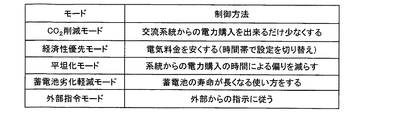
本実施形態では、図4に示すように、利用者に提示する外部動作モードとして、交流系統ESAから直流配電系統ESDに供給される電力量を少なくするCO2削減モード(第1運転モードに相当)、電力料金を抑制する経済性優先モード(第3運転モードに相当)、交流系統ESAから直流配電系統ESDへの供給電力を平坦化する平坦化モード(第4運転モードに相当)、蓄電池劣化軽減モード、外部指令モードの5つの運転モードが設定されている。In this embodiment, as shown in FIG. 4, as an external operation mode presented to the user, a CO 2 reduction mode (corresponding to the first operation mode) for reducing the amount of power supplied from the AC system ESA to the DC distribution system ESD. ), Economic priority mode to suppress power charges (corresponding to the third operation mode), flattening mode (corresponding to the fourth operation mode) for flattening the power supplied from the AC system ESA to the DC distribution system ESD, battery deterioration Five operation modes, a reduction mode and an external command mode, are set.
〈CO2削減モード〉
CO2削減モードについて、図5を基に説明する。CO2削減モードでは、太陽光発電装置2の発電量が負荷装置4の消費電力より多い場合、余った発電電力は優先的に蓄電池3に充電し、更に発電電力が余った場合は交流系統ESAに供給して売電を行う。また、太陽光発電装置2の発電量が負荷装置4の消費電力より少ない場合は、蓄電池3の電力を優先的に直流配電系統ESDに供給する。これにより、交流系統ESAからの供給電力、即ち、買電量をできるだけ減らすことができ、太陽光発電装置2の発電電力を最大限に利用することにより、CO2削減に貢献することができる。<CO 2 reduction mode>
The CO 2 reduction mode will be described with reference to FIG. In the CO 2 reduction mode, when the power generation amount of the solar
動作制御部10cは、CO2削減モードが設定されると、交流化開始電圧Vac_s、充電開始電圧Vch_s、放電開始電圧Vdch_s、直流化開始電圧Vdc_sを以下の数1に示す関係となるように設定する。When the CO 2 reduction mode is set, the
[数1]
Vac_s>Vch_s≧Vdch_s>Vdc_s[Equation 1]
Vac_s> Vch_s ≧ Vdch_s> Vdc_s
具体的には、例えば、図5に示すように、動作制御部10cは、交流化開始電圧Vac_sを380[V]に、充電開始電圧Vch_s及び放電開始電圧Vdch_sを375[V]に、直流化開始電圧Vdc_sを370[V]に夫々設定する。また、双方向DC−DCコンバータ12の最大放電電流値Idch_maxを10[A]に、定電圧運転開始電圧Vpv_maxを380[V]より大きい値(例えば、400[V])に設定する。ここで、本実施形態では、交流化開始電圧Vac_sが380[V]に設定されていることから、直流配電系統ESDの電圧Vbusは380[V]より上昇せず定電圧運転開始電圧Vpv_maxを超えることがないので、結果として、DC−DCコンバータ11は、常時MPPT制御を行い、太陽光発電装置2は最大電力を直流配電系統ESDに供給することとなる。尚、本実施形態では、充電開始電圧Vch_sと放電開始電圧Vdch_sを同じ値に設定する場合について説明したが、異なる値であっても良い。この場合には、直流配電系統ESDの電圧Vbusが、充電開始電圧Vch_s以下放電開始電圧Vdch_s以上の間は、双方向DC−DCコンバータ12は停止状態になる。
Specifically, for example, as illustrated in FIG. 5, the
直流配電系統ESDの電圧Vbusが380[V]以上の場合は、太陽光発電装置2の発電電力が非常に大きく、負荷装置4の消費電力を十分上回っているため、双方向DC−DCコンバータ12による蓄電池3への充電動作、及び、DC−ACインバータ13aによる交流系統ESAへの電力供給、即ち売電を行う。尚、このときの充電電流値Ichは15[A]に設定する。
When the voltage Vbus of the direct current distribution system ESD is 380 [V] or more, the generated power of the solar
太陽光発電装置2の発電電力の低下或いは負荷装置4の消費電力の増加により、直流配電系統ESDの電圧Vbusが低下し380[V]より低くなると、DC−ACインバータ13aは停止し売電を終了する。このとき、充電電流値Ichは、電圧Vbusが低下するに従って当初の設定値15[A]から順に下げて行く。
When the voltage Vbus of the direct current distribution system ESD decreases and becomes lower than 380 [V] due to the decrease in the generated power of the solar
直流配電系統ESDの電圧Vbusが更に低下し375[V]より低くなると、双方向DC−DCコンバータ12は、蓄電池3への充電を停止し、蓄電池3の電力を放電して直流配電系統ESDに供給する。尚、放電電流の値が最大放電電流値Idch_maxとなるまでは、直流配電系統ESDの電圧Vbusは放電開始電圧Vdch_s、ここでは375[V]で維持される。
When the voltage Vbus of the DC distribution system ESD further decreases and becomes lower than 375 [V], the bidirectional DC-
放電電流の値が最大放電電流値Idch_maxになると、直流配電系統ESDの電圧Vbusは更に低下し、直流化開始電圧Vdc_sである370[V]より低くなると、AC−DCコンバータ13bは、交流系統ESAから直流配電系統ESDに電力を供給する。そして、AC−DCコンバータ13bの電流量が最大直流化電流値Iad_max、ここでは10[A]に達するまでは、直流配電系統ESDの電圧Vbusは直流化開始電圧Vdc_sに維持される。尚、太陽光発電装置2の発電電力の低下或いは負荷装置4の消費電力の増加により、AC−DCコンバータ13bの電流量が最大直流化電流値Iad_maxより大きくなると、直流配電系統ESDの電圧Vbusは370[V]より更に低下する。
When the value of the discharge current reaches the maximum discharge current value Idch_max, the voltage Vbus of the DC distribution system ESD further decreases, and when it becomes lower than 370 [V] which is the DC conversion start voltage Vdc_s, the AC-
〈経済性優先モード〉
経済性優先モードについて、図6及び図7を基に説明する。経済性優先モードでは、電力消費にかかるコストが少なくなるように双方向DC−DCコンバータ12と第3電力変換装置13を動作させる。<Economic priority mode>
The economic priority mode will be described with reference to FIGS. In the economy priority mode, the bidirectional DC-
情報収集部10aは、経済性優先モードが設定されると、所定の時間帯別に設定された商用交流電源の買電価格及び売電価格の料金情報を取得する(第2情報収集部10a)。本実施形態では、昼(例えば午前6時〜午後6時)と夜(例えば午後6時〜午前6時)とで売電価格が別に設定されており、昼の売電価格が夜の売電価格より高くなっている場合を想定して説明する。更に、本実施形態の情報収集部10aは、蓄電池3が満充電状態であるか否かの情報を取得し動作制御部10cに出力するように構成されている。
When the economic priority mode is set, the
ここで、本実施形態では、売電価格が高く設定されている昼の時間帯では、太陽光発電装置2の発電量が負荷装置4の消費電力より多い場合、余った発電電力を蓄電池3に充電するより売電する方が経済的に有利になっている。従って、蓄電池3への充電よりも売電を優先することにより、電力消費にかかるコストを低減することができる。また、本実施形態では、売電価格が低く設定されている夜の時間帯では、蓄電池3から放電するより買電する方が経済的に有利になる。従って、蓄電池3からの放電よりも買電を優先し、蓄電池3は満充電状態でない限り充電を行う。
Here, in this embodiment, when the power generation amount of the solar
動作制御部10cは、経済性優先モードが設定されている間、売電価格が高く設定されている昼の時間帯では、以下の数2に示すように、充電開始電圧Vch_s、交流化開始電圧Vac_s、放電開始電圧Vdch_s及び直流化開始電圧Vdc_sを夫々設定する。
While the economic priority mode is set, the
[数2]
Vch_s>Vac_s
Vdch_s>Vdc_s[Equation 2]
Vch_s> Vac_s
Vdch_s> Vdc_s
また、売電価格が低く設定され太陽光発電装置2の発電電力が0になる夜の時間帯では、満充電状態ではない場合と、満充電状態の場合に分けて、満充電状態ではない場合は以下の数3に示すように、満充電状態の場合は以下の数4に示すように、充電開始電圧Vch_s、放電開始電圧Vdch_s、交流化開始電圧Vac_s及び直流化開始電圧Vdc_sを夫々設定する。
In addition, when the power selling price is set low and the generated power of the solar
[数3]
Vdch_s≦Vch_s<Vdc_s[Equation 3]
Vdch_s ≦ Vch_s <Vdc_s
[数4]
Vdch_s<Vdc_s[Equation 4]
Vdch_s <Vdc_s
具体的には、例えば、図6に示すように、動作制御部10cは、昼の時間帯の場合、充電開始電圧Vch_sを385[V]に、交流化開始電圧Vac_s及び放電開始電圧Vdch_sを375[V]に、直流化開始電圧Vdc_sを370[V]に設定する。これにより、太陽光発電装置2の発電電力が多く、負荷装置4の消費電力より大きい場合(Vbusが375[V]以上の場合)、余った発電電力は交流系統ESAに供給され売電される。尚、例えば、売電量が制限されている場合など、更に発電電力が余った場合(Vbusが385[V]以上の場合)は、蓄電池3に充電する。
Specifically, for example, as illustrated in FIG. 6, in the daytime period, the
負荷装置4の消費電力が大きくなり、発電電力が負荷装置4の消費電力より小さくなった場合(Vbusが370〜375[V]の場合)は、先ず、蓄電池3の電力を直流配電系統ESDに供給する。更に、直流配電系統ESDの電圧Vbusが低下し、放電電流の値が最大放電電流値Idch_maxより大きくなる場合(Vbusが370[V]以下の場合に相当)は、買電を行う。尚、図7に示すように、最大放電電流値Idch_maxの値は、蓄電池3の貯蔵電力量に応じて適宜設定しても良い。このように構成することで、蓄電池3が空状態になってしまうまでの時間を長くすることができる。
When the power consumption of the
また、動作制御部10cは、夜の時間帯において、蓄電池3が満充電状態ではない場合は、充電開始電圧Vch_sを365[V]に、放電開始電圧Vdch_sを360[V]に、直流化開始電圧Vdc_sを370[V]に、夫々設定する。尚、夜の時間帯では、太陽光発電装置2の発電電力が0であり、放電開始電圧Vdch_sを360[V]に設定していることから、実際には、直流配電系統ESDの電圧Vbusは、直流化開始電圧Vdc_sの370[V]より上昇しない。従って、交流化開始電圧Vac_sの設定を昼の時間帯の設定(375[V])から変更しなくても、直流配電系統ESDの電圧Vbusが370[V]以上の領域では、AC−DCコンバータ13bは停止状態になる。
Further, when the
更に、動作制御部10cは、夜の時間帯において、蓄電池3が満充電状態の場合は、放電開始電圧Vdch_sを360[V]に、直流化開始電圧Vdc_sを370[V]に夫々設定する。尚、上述したように、夜の時間帯では、太陽光発電装置2の発電電力が0であり、放電開始電圧Vdch_sを360[V]に設定していることから、実際には、直流配電系統ESDの電圧Vbusは、直流化開始電圧Vdc_sの370[V]より上昇しない。従って、充電開始電圧Vch_sの設定を昼の時間帯の設定(385[V])から変更しなくても、直流配電系統ESDの電圧Vbusが370[V]以上の領域では、双方向DC−DCコンバータ12は停止状態になる。同様に、交流化開始電圧Vac_sの設定を昼の時間帯の設定(375[V])から変更しなくても、直流配電系統ESDの電圧Vbusが370[V]以上の領域では、AC−DCコンバータ13bは停止状態になる。
Further, in the night time zone, the
〈平坦化モード〉
平坦化モードについて、図8を基に説明する。平坦化モードでは、交流系統ESAから直流配電系統ESDへの供給電力をできる限り平坦化するように動作させる。交流系統ESAからの供給電力のピーク、即ち、買電の電力のピークを抑えることで、電力会社において発電電力のピークを抑制することが期待できる。更に、マンション等の集合住宅において電力会社と電力購入契約を結ぶ場合に、買電電力のピーク値が大きいほど買電単価が高くなる場合があり、この場合には、買電電力のピーク値を抑えることで買電料金を安くすることができる。<Flattening mode>
The planarization mode will be described with reference to FIG. In the flattening mode, the operation is performed so that the power supplied from the AC system ESA to the DC power distribution system ESD is as flat as possible. By suppressing the peak of the supplied power from the AC system ESA, that is, the peak of the purchased power, it can be expected that the power company suppresses the peak of the generated power. In addition, when concluding a power purchase contract with an electric power company in an apartment house such as a condominium, the power purchase unit price may increase as the peak value of purchased power increases. Power purchases can be made cheaper by holding down.
平坦化モードが設定されると、情報収集部10aは、負荷装置4の消費電力の実績値と太陽光発電装置2の発電量の実績値を取得する(第3情報収集部10a)。具体的には、本実施形態では、情報収集部10aは、1時間毎に、負荷装置4に流れる電流値と直流配電系統の電圧Vbus、太陽光発電装置2の出力電流Ipvと出力電圧Vpvを記録する。負荷装置4の消費電力の実績値は、単位時間毎(本実施形態では1時間毎)の負荷装置に流れる電流×直流配電系統の電圧Vbusの総和で求められ、太陽光発電装置の発電量の実績値は、単位時間毎の出力電流Ipv×出力電圧Vpvの総和で求められる。ここで、図8は、負荷装置4の消費電力の実績値と太陽光発電装置2の発電量の実績値の例を示しており、破線G1は太陽光発電装置2の発電量の実績値の推移を、実線G2は負荷装置4の消費電力の実績値の推移を、実践G3は買電電力の推移を、点線G4は買電電力の最大値を夫々示している。
When the flattening mode is set, the
動作制御部10cは、平坦化モードが設定されると、情報収集部10aが取得した負荷装置4の消費電力の実績値と、太陽光発電装置2の発電量の実績値に応じて、買電電力の最大値を決定し、決定した買電電力の最大値に応じて最大直流化電流値Iad_maxを設定する。具体的には、情報収集部10aによって求められた1日の負荷装置4の消費電力の実績値と太陽光発電装置2の発電量の実績値から、1日に必要とする予定買電電力を求め、1日の予定買電電力を時間(24)で割った値に余裕を持たせた値を買電電力の最大値とし(図8の点線G4参照)、買電電力の最大値から最大直流化電流値Iad_maxを求める。
When the flattening mode is set, the
尚、本実施形態において、充電開始電圧Vch_s及び放電開始電圧Vdch_sの設定は、CO2削減モードと同じであり、共に375[V]に設定されている。また、直流化開始電圧Vdc_s及び充電開始電圧Vch_sは、本実施形態では常に買電を行うことから、例えば、400[V]に設定されている。In the present embodiment, the setting of the charge start voltage Vch_s and the discharge start voltage Vdch_s is the same as in the CO 2 reduction mode, and both are set to 375 [V]. In addition, the DC start voltage Vdc_s and the charge start voltage Vch_s are set to, for example, 400 [V] because power is always purchased in this embodiment.
具体的には、太陽光発電装置2の発電電力が0である夜の時間帯では、負荷装置4の消費電力が、買電電力の最大値G4より小さい場合は(図8の時間帯t1及びt6の場合)、直流配電系統ESDの電流値が最大直流化電流値Iad_maxより小さくなる。従って、交流系統ESAから直流配電系統ESDに電力が供給され、双方向DC−DCコンバータ12は動作を停止する。負荷装置4の消費電力が多くなり、買電電力が増加してAC−DCコンバータ13bの電流値が最大直流化電流値Iad_maxになると(図8の時間帯t5の場合)、AC−DCコンバータ13bは、電流値が最大直流化電流値Iad_maxを超えないように動作する。この場合、直流配電系統ESDの電圧Vbusが低下し、放電開始電圧Vdch_sになると双方向DC−DCコンバータ12が放電動作を行う。
Specifically, in the night time zone when the generated power of the solar
また、昼の時間帯において、負荷装置4の消費電力が、太陽光発電装置2の発電電力と買電電力の最大値G4の合計を上回る場合は(図8の時間帯t2及びt4の場合)、直流配電系統ESDの電圧Vbusが低下し(例えば、375[V]以下になると)、双方向DC−DCコンバータ12は放電動作を行う。太陽光発電装置2の発電電力が増加して、当該発電電力と買電電力の最大値G4の合計が、負荷装置4の消費電力を上回る場合は(図8の時間帯t1の場合)、直流配電系統ESDの電圧Vbusが上昇し(例えば、375[V]以上になると)、双方向DC−DCコンバータ12は充電動作を行う。尚、図8において、斜線部E1は蓄電池3への充電電力量、縦線部E2は蓄電池3からの放電電力量となっている。尚、昼の時間帯において、負荷装置4の消費電力が買電電力の最大値G4より小さい場合は(図示せず)、直流配電系統ESDの電流値が最大直流化電流値Iad_maxより小さくなり、交流系統ESAから直流配電系統ESDに電力が供給され、双方向DC−DCコンバータ12は動作を停止する。
Further, when the power consumption of the
〈蓄電池劣化軽減モード〉
蓄電池劣化軽減モードについて、図9を基に説明する。蓄電池劣化軽減モードでは、蓄電池3の寿命が長くなるように動作させる。<Storage battery deterioration reduction mode>
The storage battery deterioration reduction mode will be described with reference to FIG. In the storage battery deterioration reduction mode, the
本実施形態の蓄電池劣化軽減モードには、動作モード設定部11bが動作制御部11cに設定する内部動作モードとして、蓄電池3を通常より急速に充電させる急速充電モードと、動作モード設定部10bで予め設定された通常充放電モードと、蓄電池3を通常より緩やかに放電させる少量放電モードが設定されている。尚、本実施形態における通常充放電モードの各設定値は、CO2削減モードや経済性優先モード、平坦化モード等の各設定値と同じであっても良い。In the storage battery deterioration reduction mode of the present embodiment, as an internal operation mode set by the operation mode setting unit 11b in the operation control unit 11c, a quick charge mode for charging the
ここで、本実施形態の蓄電池3は、上述したようにリチウムイオン電池を想定している。リチウムイオン電池は、急速放電及び急速充電を交互に繰り返すと、内部抵抗が徐々に増大して出力劣化現象が生じる。更に、この二次電池の出力劣化現象に伴って、発電要素の正極板と負極板との間に保持されている保持電解液中のリチウムイオンの濃度が変動する場合がある。保持電解液中のリチウムイオンの濃度が変動すると、リチウムイオン電池の内部抵抗が増大することがある。尚、リチウムイオン電池の劣化が大きいと判定された場合には、蓄電池3の充放電の条件を適切に調整して充放電を繰り返せば、内部抵抗の増大を抑制して劣化を抑制し、蓄電池3の寿命をより長く保つことができる。そこで、本実施形態では、蓄電池3の内部抵抗の増大を抑制し、劣化を抑制するために、蓄電池3が劣化していると判定された場合は、通常より急速に充電させる急速充電モードを実行し、充電が終了すると、通常より緩やかに放電する少量放電モードを実行し、放電が終了すると、急速充電モードを実行する。
Here, the
本実施形態の情報収集部10aは、蓄電池劣化軽減モードが設定されると、逐次、電力貯蔵装置の劣化情報を取得する(第4情報収集部10a)。具体的には、本実施形態の情報収集部10aは、リチウムイオン電池のリチウムイオンの濃度情報や、内部抵抗の測定値を取得する。
When the storage battery deterioration reduction mode is set, the
動作モード設定部10bは、外部入力により蓄電池劣化軽減モードが設定されている間、劣化情報に基づいて電力貯蔵装置が劣化しているか否かを判定し、電力貯蔵装置が劣化していると判定した場合は、動作制御部10cに対して急速充電モードを設定し、電力貯蔵装置が満充電になると動作制御部10cに対して少量放電モードを設定し、電力貯蔵装置の放電が終了すると動作制御部10cに対して急速充電モードを設定し、電力貯蔵装置が満充電になると、動作制御部10cに対して通常充放電モードを設定する。
The operation
動作制御部10cは、急速充電モードが設定されると、電力貯蔵装置の特性に応じて充電電流値Ichを通常充放電モードにおける充電電流値Ichより大きい値に設定し、少量放電モードが設定されると、電力貯蔵装置の特性に応じて最大放電電流値Idch_maxを通常充放電モードにおける最大放電電流値Idch_maxより小さい値に設定する。
When the quick charging mode is set, the
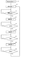
ここで、図9は、蓄電池劣化軽減モードが設定されている場合の動作を示している。図1に示す表示装置5から蓄電池劣化軽減モードが設定されると(ステップ#1)、動作モード設定部10bは、先ず、動作制御部10cに対して通常充放電モードを設定する(ステップ#2)。動作制御部10cは、通常充放電モードに応じて各第1制御パラメータ及び第2制御パラメータを設定する。
Here, FIG. 9 shows an operation when the storage battery deterioration reduction mode is set. When the storage battery deterioration reduction mode is set from the
続いて、動作モード設定部10bは、劣化情報に基づいて蓄電池3が劣化しているか否かを判定し(ステップ#3)、蓄電池3が劣化していると判定した場合は(ステップ#3でYES分岐)、動作制御部10cに対して急速充電モードを設定する(ステップ#4)。動作制御部10cは、急速充電モードが設定されると、充電電流値Ichを通常充放電モードにおける充電電流値Ichより大きい値に設定する。引き続き、動作モード設定部10bは、蓄電池3が満充電になると(ステップ#5でYES分岐)、動作制御部10cに対して少量放電モードを設定する(ステップ#6)。動作制御部10cは、少量放電モードが設定されると、最大放電電流値Idch_maxを通常充放電モードにおける最大放電電流値Idch_maxより小さい値に設定する。引き続き、動作モード設定部10bは、蓄電池3の残量が0になると(ステップ#7でYES分岐)、動作制御部10cに対して再度急速充電モードを設定する(ステップ#8)。尚、動作制御部10cは、ステップ#4で充電電流値Ichを通常充放電モードにおける充電電流値Ichより大きい値に設定しているので、充電電流値Ichの設定は変更しない。引き続き、動作モード設定部10bは、蓄電池3が満充電になると(ステップ#9でYES分岐)、動作制御部10cに対して通常充放電モードを設定する(ステップ#2)。動作制御部10cは、通常充放電モードが設定されると、充電電流値Ich及び最大放電電流値Idch_maxの設定を通常充放電モードの設定にする。
Subsequently, the operation
〈外部指令モード〉
外部指令モードでは、外部から第1制御パラメータ及び第2制御パラメータの各設定値を取得する。このように構成することにより、例えば、外部動作モードを任意に追加することが可能になる。<External command mode>
In the external command mode, the set values of the first control parameter and the second control parameter are acquired from the outside. With this configuration, for example, an external operation mode can be arbitrarily added.
〈第2実施形態〉
本発明システム1の第2実施形態について、図10を基に説明する。上記第1実施形態のCO2削減モードでは、固定的に第1制御パラメータを設定したが、本実施形態のCO2削減モードでは、蓄電池3の残量に応じて第1制御パラメータの設定を切り替えるように設定する(第2運転モードに相当)。ここでは、第1制御パラメータである放電開始電圧Vdch_s及び充電開始電圧Vch_sを、蓄電池3の残量が多い程大きくなるように設定する。Second Embodiment
A second embodiment of the
本実施形態の情報収集部10aは、CO2削減モードが設定されている間、第2電力変換装置から電力貯蔵装置の貯蔵電力量を適宜、例えば、10〜60分等の一定の間隔で取得する(第1情報収集部10a)。While the CO 2 reduction mode is set, the
本実施形態の動作制御部10cは、第2運転モードが設定されている間、充電開始電圧Vch_s及び放電開始電圧Vdch_sを、貯蔵電力量に応じて適宜設定する。ここで、図10は、本実施形態におけるCO2削減モードの電圧設定方法を示している。The
本実施形態では、図10に示すように、蓄電池3の残量が、10%以下の「空」、10%〜30%の「少」、30%〜70%の「中」、70%〜90%の「多」、90%以上の「満」の5つの場合に分けて第1制御パラメータを切り替える場合を想定して説明する。
In this embodiment, as shown in FIG. 10, the remaining amount of the
第1制御パラメータは、放電開始電圧Vdch_sを、蓄電池3の残量が「空」の場合は0[V]に、「少」及び「中」の場合は360[V]に、「多」及び「満」の場合は375[V]に、夫々設定し、充電開始電圧Vch_sを、蓄電池3の残量が「空」及び「少」の場合は365[V]に、「中」の場合は370[V]に、「多」の場合は375[V]に、「満」の場合は400[V]に、夫々設定する。また、双方向DC−DCコンバータ12の最大放電電流値Idch_maxを10[A]に設定する。
The first control parameter is that the discharge start voltage Vdch_s is 0 [V] when the remaining amount of the
また、第2制御パラメータは、交流化開始電圧Vac_sを380[V]に、直流化開始電圧Vdc_sを370[V]に、AC−DCコンバータ13bの最大直流化電流値Iad_maxを10[A]に夫々設定する。
The second control parameters are: the AC conversion start voltage Vac_s is 380 [V], the DC conversion start voltage Vdc_s is 370 [V], and the maximum DC conversion current value Iad_max of the AC-
以上のように設定することにより、蓄電池3の残量が「満」の場合は、図10に示すように、蓄電池3の残量が非常に多く充電する必要がないため、双方向DC−DCコンバータ12による充電動作は行われず、買電より放電動作が優先して行われる。
By setting as described above, when the remaining amount of the
また、蓄電池3の残量が「多」の場合は、図5及び図10に示すように、第1制御パラメータ及び第2制御パラメータの設定が、第1実施形態のCO2削減モードにおける第1制御パラメータ及び第2制御パラメータの設定と同じに設定されている。「満」の場合と同様に、買電より放電動作が優先して行われるが、太陽光発電装置2の発電電力が負荷装置4の消費電力より多い場合(直流配電系統ESDの電圧Vbusが充電開始電圧Vch_sより大きい場合)には、充電動作が行われる。Further, when the remaining amount of the
蓄電池3の残量が「中」の場合は、図10に示すように、充電開始電圧Vch_s及び放電開始電圧Vdch_sが「多」の場合より低く設定されており、太陽光発電装置2の発電電力が負荷装置4の消費電力より小さい場合(直流配電系統ESDの電圧Vbusが直流化開始電圧Vdc_sより小さい場合)、放電動作より買電が優先して行われる。
When the remaining amount of the
蓄電池3の残量が「少」の場合は、蓄電池3の残量が足りなくなるのを防止するために、直流配電系統ESDの電圧Vbusが充電開始電圧Vch_sより大きく直流化開始電圧Vdc_sより小さい場合に、買電による電力を蓄電池3に充電する。尚、負荷装置4の消費電力が大きく直流配電系統ESDの電圧Vbusが放電開始電圧Vdch_sを下回る場合は、放電動作を行う。
When the remaining amount of the
蓄電池3の残量が「空」の場合は、蓄電池3の残量が「少」の場合と同様に、直流配電系統ESDの電圧Vbusが充電開始電圧Vch_sより大きく直流化開始電圧Vdc_sより小さい場合に、買電による電力を蓄電池3に充電する。また、放電動作は行われない。
When the remaining amount of the
蓄電池3の残量に応じて第1制御パラメータの設定を切り替えることで、太陽光発電装置2の発電量が少ない場合や、負荷装置4の消費電力量が多い場合でも、蓄電池3の残量が不足するのを防止することができる。
By switching the setting of the first control parameter according to the remaining amount of the
〈第3実施形態〉
本発明システム1の第3実施形態について、図11を基に説明する。上記第1実施形態の経済性優先モードでは、昼の時間帯と夜の時間帯で売電価格が異なる場合を想定したが、本実施形態では、更に、夜の時間帯において一定量以上の電力を購入すると買電価格が高くなる場合を想定して説明する。<Third Embodiment>
A third embodiment of the
本実施形態の経済性優先モードでは、夜の時間帯において交流系統ESAから直流配電系統ESDに供給される電力量を一定量以下に抑える制御を行う。 In the economical priority mode of the present embodiment, control is performed to keep the amount of power supplied from the AC system ESA to the DC distribution system ESD to a certain level or less in the night time zone.
具体的には、本実施形態の動作制御部10cは、買電価格が高くなる電力量に応じて最大直流化電流値Iad_maxを設定する。ところで、本実施形態の場合、交流系統ESAから直流配電系統ESDへの電力供給が制限されるため、負荷装置4の消費電力が大きくなり、AC−DCコンバータ13bの電流値が最大直流化電流値Iad_maxに達すると、直流配電系統ESDの電圧Vbusが低下する。従って、本実施形態の動作制御部10cは、図11に示すように、充電電流Ichを、直流配電系統ESDの電圧Vbusの低下に応じて減少するように設定する。これにより、直流配電系統ESDの電圧Vbusを安定させることが可能になる。
Specifically, the
〈第4実施形態〉
本発明システム1の第4実施形態について、図12を基に説明する。<Fourth embodiment>
A fourth embodiment of the
本実施形態の本発明システム1Bは、図12に示すように、上記第1実施形態の各構成に加え、直流配電系統ESDとの接続切断を自在に構成された第2電力貯蔵装置と直流配電系統ESDとの間で電圧変換して、一方側から他方側へ電力供給する第4電力変換装置14を備えている。
As shown in FIG. 12, the
蓄電池6は、本実施形態では、第2電力貯蔵装置の一例であり、電気自動車やハイブリッドカーに搭載される蓄電池を想定している。尚、本実施形態の蓄電池6は、リチウムイオン電池を想定して説明するが、他の電池であっても良い。蓄電池6は、直流配電系統ESDに固定的に設置された第4電力変換装置14とコネクタで接続するように構成されている。
In the present embodiment, the
双方向DC−DCコンバータ14は、本実施形態では、第4電力変換装置の一例であり、双方向DC−DCコンバータ12と同様に、充電開始電圧Vch_s、放電開始電圧Vdch_s、充電電流値Ich、充電電圧値Vch、放電電圧値Vdch及び最大放電電流値Idch_maxに応じて、電力供給方向、運転開始及び運転停止の制御を行うように構成されている。
In the present embodiment, the bidirectional DC-
本実施形態の情報収集部10aは、蓄電池6が切断または接続された場合に、切断または接続された蓄電池6と切断または接続を示す接続情報を取得するように構成されている。また、本実施形態の情報収集部10aは、接続されている蓄電池全体の容量、各蓄電池の残量の情報を取得する。
When the
本実施形態の動作制御部10cは、情報収集部10aから蓄電池6の接続情報を取得し、蓄電池6が接続された場合は、接続された蓄電池6に対応する双方向DC−DCコンバータ14を動作させ、充電開始電圧Vch_s、放電開始電圧Vdch_s、充電電流値Ich、充電電圧値Vch、放電電圧値Vdch及び最大放電電流値Idch_maxを設定する。また、蓄電池6が切断された場合は、切断された蓄電池6に対応する双方向DC−DCコンバータ14を停止させる。
The
尚、本実施形態では、蓄電池6が車載の蓄電池を想定していることから、蓄電池6の充電を、他の固定的に接続された蓄電池3より優先して行うように構成しても良い。具体的には、動作制御部10cは、蓄電池6の充電開始電圧Vch_sを蓄電池3の充電開始電圧Vch_sより低い値に設定する。
In this embodiment, since the
本実施形態では、接続切断自在に構成された蓄電池6を利用することができるので、例えば、停電時や、負荷装置の消費電力が一時的に増大した場合で買電を抑えたい場合等に対応できる。
In this embodiment, since the
〈別実施形態〉
本発明システム1の別実施形態について説明する。<Another embodiment>
Another embodiment of the
〈1〉上記第1実施形態の経済性優先モードにおいて、情報収集部10aを、天気予報の情報を取得するように構成し、次の日の発電量を予測して、蓄電池3の充電量及び放電量を調整するように制御しても良い。例えば、次の日が曇りで発電量が少ないと予測される場合には、蓄電池3の残量が多くなるように、充電開始電圧Vch_s及び放電開始電圧Vdch_sを低く設定しても良い。
<1> In the economic priority mode of the first embodiment, the
〈2〉上記第1実施形態の平坦化モードにおいて、電力会社から売電の電力量を制限された場合に、情報収集部10aが、電力の買い取り量の最大値を取得し、動作制御部10cが、電力の買い取り量の最大値に応じて最大直流化電流値Iad_maxを設定するように構成しても良い。
<2> In the flattening mode of the first embodiment, when the amount of power sold is limited by the power company, the
〈3〉上記第1〜第4実施形態では、簡単のために第1電力貯蔵装置3が1つの蓄電池3で構成されている場合を想定して説明したが、第1電力貯蔵装置3は、複数の蓄電池を並列に接続して構成しても良い。
<3> In the first to fourth embodiments, the case where the first
第1電力貯蔵装置3が複数の蓄電池を並列に接続して構成されている場合、情報収集部10aは、蓄電池毎に適宜残量を取得し、動作制御部10cは、図13に示すように、情報収集部10aが取得した蓄電池3の残量に応じて、放電開始電圧Vdch_sの設定を適宜切り替える。
When the first
このように構成することで、残量の多い蓄電池3から優先的に放電動作が開始されることになる。一部の蓄電池3のみが充放電を繰り返すと、当該一部の蓄電池3のみが劣化することになるが、本実施形態では、残量の多い蓄電池3から優先的に放電動作が開始されるので、結果として、複数の蓄電池3の残量が均一化され、一部の蓄電池3のみが充放電されて劣化するのを防止できる。
By comprising in this way, discharge operation is started preferentially from the
〈4〉上記第1〜第4実施形態では、各電力変換装置が電力供給方向、運転開始及び運転停止の制御を行う場合について説明したが、これに限るものではなく、動作制御部10cが、各電力変換装置の電力供給方向、運転開始及び運転停止の制御を行うように構成しても良い。
<4> In the first to fourth embodiments described above, the case where each power conversion device performs control of the power supply direction, operation start, and operation stop is not limited to this, and the
〈5〉上記第1〜第4実施形態では、CO2削減モード、経済性優先モード、平坦化モード、蓄電池劣化軽減モードは、夫々別々に設定するように構成したが、これに限るものではない。例えば、蓄電池劣化軽減モードを、利用者が選択するのではなく常時設定されるように構成し、蓄電池劣化軽減モードの通常充放電モードとして、CO2削減モード、経済性優先モード、平坦化モード及び外部指令モードの何れかを実行するように構成し、利用者が通常充放電モードで実行する動作モードを表示装置5により選択するように構成しても良い。<5> In the first to fourth embodiments, the CO 2 reduction mode, the economy priority mode, the flattening mode, and the storage battery deterioration reduction mode are configured to be set separately, but the present invention is not limited to this. . For example, the storage battery deterioration reduction mode is configured not to be selected by the user but always set, and as the normal charge / discharge mode of the storage battery deterioration reduction mode, a CO 2 reduction mode, an economic priority mode, a flattening mode, and It may be configured to execute one of the external command modes, and the
また、蓄電池劣化軽減モードを、利用者が選択するのではなく常時設定されるように構成し、蓄電池3が劣化していると判定された場合に、充電動作における充電電流値Ichの設定を急速充電モードにおける充電電流値Ichの設定と同じにし、放電動作における最大放電電流値Idch_maxの設定を少量放電モードにおける最大放電電流値Idch_maxの設定と同じにして、利用者によって設定された外部動作モード(CO2削減モード、経済性優先モード、平坦化モード、外部指令モード)を実行するように構成しても良い。In addition, the storage battery deterioration reduction mode is configured so that it is always set instead of being selected by the user, and when it is determined that the
〈6〉上記第1〜第4実施形態では、蓄電池劣化軽減モードは、第1電力貯蔵装置に対して実行するように構成したが、第2電力貯蔵装置に対しても実行するように構成しても良い。 <6> In the first to fourth embodiments, the storage battery deterioration reduction mode is configured to be executed for the first power storage device, but is also configured to be executed for the second power storage device. May be.
〈7〉上記第1〜第4実施形態において、停電や給電制限等の異常事態が発生した場合、外部動作モードの設定が通常のままでは、本発明システム1が正常に動作できなくなることが考えられる。具体的には、例えば、停電が発生するとAC−DCコンバータ13bが停止して直流化開始電圧Vdc_sの設定が無効になる。従って、異常事態に応じて第1制御パラメータ及び第2制御パラメータを調整するための情報を記録したテーブルを予め用意しておき、異常事態が発生した場合は、発生した異常事態に対応したテーブルを用いて第1制御パラメータ及び第2制御パラメータを調整するように構成しても良い。
<7> In the first to fourth embodiments described above, when an abnormal situation such as a power failure or power supply restriction occurs, the
1 本発明に係る直流配電システム
1A 本発明に係る直流配電システム
1B 本発明に係る直流配電システム
2 太陽光発電装置
3 蓄電池(第1電力貯蔵装置)
4 負荷装置
5 表示装置
6 蓄電池(第2電力貯蔵装置)
10 動作制御装置
10a 情報収集部
10b 動作モード設定部
10c 動作制御部
11 DC−DCコンバータ(第1電力変換装置)
12 双方向DC−DCコンバータ(第2電力変換装置)
13 第3電力変換装置
13a DC−ACインバータ
13b AC−DCコンバータ
14 双方向DC−DCコンバータ(第4電力変換装置)
100 従来技術に係る直流配電システム
101 系統連系ユニット
102 電力貯蔵ユニット
103 フライホイールユニット
104 風力発電ユニット
105 太陽光発電ユニット
106 負荷ユニット
ESD 直流配電系統
ESA 交流系統1 DC
4
DESCRIPTION OF
12 Bidirectional DC-DC converter (second power converter)
13
DESCRIPTION OF
Claims (6)
前記直流配電系統に太陽光発電装置の発電電力を電圧変換して供給する第1電力変換装置と、
前記直流配電系統に常時接続された第1電力貯蔵装置と前記直流配電系統との間で電圧変換して、一方側から他方側へ電力供給する第2電力変換装置と、
交流系統と前記直流配電系統との間で電力変換して、一方側から他方側へ電力供給する第3電力変換装置と、
を備えた直流配電システムであって、
前記直流配電システムの動作モードを設定するための動作モード決定情報に応じて、前記動作モードを設定する動作モード設定部と、
前記動作モード設定部によって設定された前記動作モードに応じて、前記第2電力変換装置に第1制御パラメータを、前記第3電力変換装置に第2制御パラメータを夫々設定する動作制御部と、
前記第1制御パラメータ及び前記第2制御パラメータを設定するためのパラメータ設定情報を取得する情報収集部と、を備え、
第2電力変換装置は、前記直流配電系統の電圧と前記第1制御パラメータに応じて、電力供給方向、運転開始及び運転停止の制御を行い、
第3電力変換装置は、前記直流配電系統の電圧と前記第2制御パラメータに応じて、電力供給方向、運転開始及び運転停止の制御を行い、
前記第1制御パラメータは、前記直流配電系統から前記第1電力貯蔵装置への電力供給を開始する前記直流配電系統の電圧を規定する充電開始電圧、及び、前記第1電力貯蔵装置から前記直流配電系統への電力供給を開始する前記直流配電系統の電圧を規定する放電開始電圧を含み、
前記第2制御パラメータは、前記直流配電系統から前記交流系統への電力供給を開始する前記直流配電系統の電圧を規定する交流化開始電圧、及び、前記交流系統から前記直流配電系統への電力供給を開始する前記直流配電系統の電圧を規定する直流化開始電圧を含み、
前記動作制御部は、前記動作モード設定部によって前記動作モードが変更された場合に、前記情報収集部が取得した前記パラメータ設定情報に基づいて前記第1制御パラメータ及び前記第2制御パラメータを設定し、
前記動作モードは、前記交流系統から前記直流配電系統に供給される電力量を少なくする第1運転モードを含み、
前記動作制御部は、前記第1運転モードが設定されると、前記交流化開始電圧が前記充電開始電圧より大きく、前記放電開始電圧が前記直流化開始電圧より大きくなるように、前記第1制御パラメータ及び前記第2制御パラメータを設定することを特徴とする直流配電システム。 A DC distribution system for supplying DC power to the load device;
A first power converter that converts the voltage of the generated power of the solar power generator to supply to the DC distribution system;
A second power conversion device that performs voltage conversion between the first power storage device always connected to the DC distribution system and the DC distribution system and supplies power from one side to the other;
A third power converter for converting power between the AC system and the DC power distribution system and supplying power from one side to the other;
A DC power distribution system comprising:
In accordance with operation mode determination information for setting the operation mode of the DC power distribution system, an operation mode setting unit that sets the operation mode;
An operation control unit configured to set a first control parameter in the second power converter and a second control parameter in the third power converter according to the operation mode set by the operation mode setting unit;
An information collecting unit for obtaining parameter setting information for setting the first control parameter and the second control parameter ;
The second power converter performs power supply direction, operation start and operation stop control according to the voltage of the DC distribution system and the first control parameter,
The third power converter, in response to said voltage and said second control parameter of the DC power distribution system, the power supply direction, have row control operation start and operation stop,
The first control parameter includes a charging start voltage that defines a voltage of the DC power distribution system that starts power supply from the DC power distribution system to the first power storage device, and a DC power distribution from the first power storage device. Including a discharge start voltage defining a voltage of the DC distribution system for starting power supply to the system,
The second control parameter includes an AC start voltage that defines a voltage of the DC distribution system that starts power supply from the DC distribution system to the AC system, and power supply from the AC system to the DC distribution system Including a DC start voltage defining the voltage of the DC distribution system to start
The operation control unit sets the first control parameter and the second control parameter based on the parameter setting information acquired by the information collecting unit when the operation mode is changed by the operation mode setting unit. ,
The operation mode includes a first operation mode for reducing the amount of power supplied from the AC system to the DC distribution system,
When the first operation mode is set, the operation control unit controls the first control so that the AC start voltage is greater than the charge start voltage and the discharge start voltage is greater than the DC start voltage. A DC power distribution system, wherein a parameter and the second control parameter are set .
前記直流配電系統に太陽光発電装置の発電電力を電圧変換して供給する第1電力変換装置と、
前記直流配電系統に常時接続された第1電力貯蔵装置と前記直流配電系統との間で電圧変換して、一方側から他方側へ電力供給する第2電力変換装置と、
交流系統と前記直流配電系統との間で電力変換して、一方側から他方側へ電力供給する第3電力変換装置と、
を備えた直流配電システムであって、
前記直流配電システムの動作モードを設定するための動作モード決定情報に応じて、前記動作モードを設定する動作モード設定部と、
前記動作モード設定部によって設定された前記動作モードに応じて、第1制御パラメータと第2制御パラメータを夫々設定する動作制御部と、
前記第1制御パラメータ及び前記第2制御パラメータを設定するためのパラメータ設定情報を取得する情報収集部と、を備え、
前記動作制御部は、前記直流配電系統の電圧と前記第1制御パラメータに応じて、第2電力変換装置の電力供給方向、運転開始及び運転停止の制御を行い、前記直流配電系統の電圧と前記第2制御パラメータに応じて、第3電力変換装置の電力供給方向、運転開始及び運転停止の制御を行い、
前記第1制御パラメータは、前記直流配電系統から前記第1電力貯蔵装置への電力供給を開始する前記直流配電系統の電圧を規定する充電開始電圧、及び、前記第1電力貯蔵装置から前記直流配電系統への電力供給を開始する前記直流配電系統の電圧を規定する放電開始電圧を含み、
前記第2制御パラメータは、前記直流配電系統から前記交流系統への電力供給を開始する前記直流配電系統の電圧を規定する交流化開始電圧、及び、前記交流系統から前記直流配電系統への電力供給を開始する前記直流配電系統の電圧を規定する直流化開始電圧を含み、
前記動作制御部は、前記動作モード設定部によって前記動作モードが変更された場合に、前記情報収集部が取得した前記パラメータ設定情報に基づいて前記第1制御パラメータ及び前記第2制御パラメータを設定し、
前記動作モードは、前記交流系統から前記直流配電系統に供給される電力量を少なくする第1運転モードを含み、
前記動作制御部は、前記第1運転モードが設定されると、前記交流化開始電圧が前記充電開始電圧より大きく、前記放電開始電圧が前記直流化開始電圧より大きくなるように、前記第1制御パラメータ及び前記第2制御パラメータを設定することを特徴とする直流配電システム。 A DC distribution system for supplying DC power to the load device;
A first power converter that converts the voltage of the generated power of the solar power generator to supply to the DC distribution system;
A second power conversion device that performs voltage conversion between the first power storage device always connected to the DC distribution system and the DC distribution system and supplies power from one side to the other;
A third power converter for converting power between the AC system and the DC power distribution system and supplying power from one side to the other;
A DC power distribution system comprising:
In accordance with operation mode determination information for setting the operation mode of the DC power distribution system, an operation mode setting unit that sets the operation mode;
An operation control unit for setting the first control parameter and the second control parameter in accordance with the operation mode set by the operation mode setting unit;
An information collecting unit for obtaining parameter setting information for setting the first control parameter and the second control parameter ;
The operation control unit controls the power supply direction, operation start and operation stop of the second power converter according to the voltage of the DC distribution system and the first control parameter, and the voltage of the DC distribution system and the According to the second control parameter, the power supply direction of the third power converter, the operation start and the operation stop control are performed,
The first control parameter includes a charging start voltage that defines a voltage of the DC power distribution system that starts power supply from the DC power distribution system to the first power storage device, and a DC power distribution from the first power storage device. Including a discharge start voltage defining a voltage of the DC distribution system for starting power supply to the system,
The second control parameter includes an AC start voltage that defines a voltage of the DC distribution system that starts power supply from the DC distribution system to the AC system, and power supply from the AC system to the DC distribution system Including a DC start voltage defining the voltage of the DC distribution system to start
The operation control unit sets the first control parameter and the second control parameter based on the parameter setting information acquired by the information collecting unit when the operation mode is changed by the operation mode setting unit. ,
The operation mode includes a first operation mode for reducing the amount of power supplied from the AC system to the DC distribution system,
When the first operation mode is set, the operation control unit controls the first control so that the AC start voltage is greater than the charge start voltage and the discharge start voltage is greater than the DC start voltage. A DC power distribution system, wherein a parameter and the second control parameter are set .
前記第2運転モードが設定されている間、前記第2電力変換装置から前記第1電力貯蔵装置の貯蔵電力量を適宜取得する第1情報収集部を備え、
前記動作制御部は、前記第2運転モードが設定されている間、前記電力貯蔵量が大きいほど前記充電開始電圧及び前記放電開始電圧が大きくなるように設定することを特徴とする請求項1または2に記載の直流配電システム。 The operation mode includes a second operation mode in which the setting of the first control parameter is switched according to the power storage amount of the first power storage device,
While the second operation mode is set, a first information collection unit that appropriately acquires the stored power amount of the first power storage device from the second power conversion device,
The operation control unit is configured during the second operating mode is set, according to claim 1 wherein the charging start voltage and the discharge starting voltage as the power storage amount is large and setting to be larger or 2. The DC power distribution system according to 2.
前記動作モードは、電力料金を抑制する第3運転モードを含み、
前記第3運転モードが設定されると、所定の時間帯別に設定された前記商用交流電源の買電価格及び売電価格の料金情報を取得する第2情報収集部を備え、
前記動作制御部は、前記第3運転モードが設定されている間、前記売電価格が高く設定されている時間帯では、前記充電開始電圧を前記交流化開始電圧より大きく、且つ、前記放電開始電圧を前記直流化開始電圧より大きく設定し、
前記売電価格が低く設定されている時間帯では、前記充電開始電圧を前記直流化開始電圧より小さく設定することを特徴とする請求項1〜3の何れか1項に記載の直流配電システム。 The AC system is connected to a commercial AC power source,
The operation mode includes a third operation mode for suppressing power charges,
When the third operation mode is set, a second information collecting unit that acquires charge information of the commercial AC power supply price and the power sale price set for each predetermined time zone,
While the third operation mode is set, the operation control unit is configured such that the charge start voltage is greater than the AC start voltage and the discharge start is performed in a time zone in which the power selling price is set high. Set the voltage larger than the DC conversion start voltage,
In the time zone in which the power selling price is set low, the DC power distribution system according to any one of claims 1 to 3, characterized in that to set the charging start voltage smaller than the direct current start voltage.
前記動作制御部は、前記充電電流値を、前記直流配電系統の電圧の低下に応じて減少するように設定することを特徴とする請求項4に記載の直流配電システム。 The first control parameter includes a charging current value when power is supplied from the DC distribution system to the first power storage device,
The DC power distribution system according to claim 4 , wherein the operation control unit sets the charging current value so as to decrease in accordance with a decrease in voltage of the DC power distribution system.
前記動作モードは、前記交流系統から前記直流配電系統への供給電力を平坦化する第4運転モードを含み、
前記第4運転モードが設定されると、前記負荷装置の消費電力の実績値と前記太陽光発電装置の発電量の実績値を取得する第3情報収集部を備え、
前記動作制御部は、前記第4運転モードが設定されると、前記消費電力の実績値と前記発電量の実績値に応じて、前記最大直流化電流値を設定することを特徴とする請求項1〜5の何れか1項に記載の直流配電システム。
The second control parameter, see contains a maximum direct current value of the current supplied from the AC system in the third power converter to the DC distribution system,
The operation mode includes a fourth operation mode for flattening power supplied from the AC system to the DC distribution system,
When the fourth operation mode is set, the system includes a third information collection unit that acquires the actual value of the power consumption of the load device and the actual value of the power generation amount of the solar power generation device,
The operation control unit, when the fourth operation mode is set, sets the maximum DC current value according to the actual value of the power consumption and the actual value of the power generation amount. The DC power distribution system according to any one of 1 to 5 .
Priority Applications (1)
| Application Number | Priority Date | Filing Date | Title |
|---|---|---|---|
| JP2012521368A JP5584763B2 (en) | 2010-06-22 | 2011-05-02 | DC power distribution system |
Applications Claiming Priority (4)
| Application Number | Priority Date | Filing Date | Title |
|---|---|---|---|
| JP2010141500 | 2010-06-22 | ||
| JP2010141500 | 2010-06-22 | ||
| JP2012521368A JP5584763B2 (en) | 2010-06-22 | 2011-05-02 | DC power distribution system |
| PCT/JP2011/060512 WO2011162025A1 (en) | 2010-06-22 | 2011-05-02 | Dc power distribution system |
Publications (2)
| Publication Number | Publication Date |
|---|---|
| JPWO2011162025A1 JPWO2011162025A1 (en) | 2013-08-19 |
| JP5584763B2 true JP5584763B2 (en) | 2014-09-03 |
Family
ID=45371228
Family Applications (1)
| Application Number | Title | Priority Date | Filing Date |
|---|---|---|---|
| JP2012521368A Expired - Fee Related JP5584763B2 (en) | 2010-06-22 | 2011-05-02 | DC power distribution system |
Country Status (3)
| Country | Link |
|---|---|
| EP (1) | EP2587623B1 (en) |
| JP (1) | JP5584763B2 (en) |
| WO (1) | WO2011162025A1 (en) |
Families Citing this family (38)
| Publication number | Priority date | Publication date | Assignee | Title |
|---|---|---|---|---|
| US9093862B2 (en) * | 2009-01-16 | 2015-07-28 | Zbb Energy Corporation | Method and apparatus for controlling a hybrid power system |
| JP5541982B2 (en) * | 2010-06-28 | 2014-07-09 | シャープ株式会社 | DC power distribution system |
| JP5843624B2 (en) * | 2012-01-17 | 2016-01-13 | 三菱電機株式会社 | Power conversion system for grid connection |
| JP2013158132A (en) * | 2012-01-30 | 2013-08-15 | Kawamura Electric Inc | Photovoltaic power generation system |
| WO2013175772A1 (en) * | 2012-05-25 | 2013-11-28 | パナソニック株式会社 | In-vehicle power supply device and photovoltaic power generation device |
| JP5882845B2 (en) * | 2012-06-27 | 2016-03-09 | 東芝三菱電機産業システム株式会社 | Power storage type solar power generation system |
| JP2014130716A (en) * | 2012-12-28 | 2014-07-10 | Nec Corp | Storage battery system and power output method |
| CN104079233B (en) * | 2013-03-25 | 2017-07-11 | 北汽福田汽车股份有限公司 | A kind of method of energy-storage battery cabinet capacity in calculating photovoltaic generating system |
| JP5995804B2 (en) * | 2013-08-09 | 2016-09-21 | 三菱重工業株式会社 | Storage system management device and control target value determination method |
| DE102014206892A1 (en) * | 2013-08-26 | 2015-02-26 | Robert Bosch Gmbh | Method and control device for operating an energy storage device for a photovoltaic system |
| DE102013109608B4 (en) | 2013-09-03 | 2019-01-10 | Sma Solar Technology Ag | Method and feed-in control for feeding electrical power into a line branch |
| CN103414215A (en) * | 2013-09-10 | 2013-11-27 | 南车株洲电力机车研究所有限公司 | Distributed power supply system |
| JP6168938B2 (en) * | 2013-09-11 | 2017-07-26 | 三菱電機株式会社 | Charge / discharge control device, charge / discharge control method, and program |
| JP6085544B2 (en) * | 2013-09-19 | 2017-02-22 | 三菱重工業株式会社 | Rapid charging equipment for electric vehicles, energy management method for charging equipment, and charging equipment system |
| FR3016702B1 (en) * | 2014-01-17 | 2017-08-04 | Blue Solutions | METHOD AND SYSTEM FOR MANAGING A PLURALITY OF ENERGY STORAGE ASSEMBLY |
| JP6053711B2 (en) * | 2014-02-27 | 2016-12-27 | 三菱重工業株式会社 | Charging facility management apparatus, charging facility management method, and program |
| JP6678393B2 (en) * | 2015-04-14 | 2020-04-08 | 古河電気工業株式会社 | Power storage system and control method thereof |
| JP6635671B2 (en) * | 2015-04-14 | 2020-01-29 | 三菱電機株式会社 | Power converter |
| JP6172868B2 (en) * | 2015-08-31 | 2017-08-02 | 興和株式会社 | Power supply |
| CN105186575B (en) * | 2015-11-05 | 2017-12-26 | 上海科泰电源股份有限公司 | A kind of thermal power plant's emergency power supply diesel generating set parallel connection system |
| US10700524B2 (en) * | 2016-01-27 | 2020-06-30 | Mitsubishi Electric Corporation | Management device and control method |
| DE102016007598A1 (en) * | 2016-06-21 | 2017-12-21 | Karlsruher Institut für Technologie | Energy management unit, energy supply system and energy management process |
| JP6847604B2 (en) * | 2016-08-30 | 2021-03-24 | 株式会社アイケイエス | Power interchange system |
| US11309714B2 (en) | 2016-11-02 | 2022-04-19 | Tesla, Inc. | Micro-batteries for energy generation systems |
| JP6565086B2 (en) * | 2016-11-29 | 2019-08-28 | 三菱重工業株式会社 | Charging equipment management device |
| WO2018142579A1 (en) * | 2017-02-03 | 2018-08-09 | 東芝三菱電機産業システム株式会社 | Uninterruptible power supply device |
| JP6832511B2 (en) * | 2017-03-30 | 2021-02-24 | パナソニックIpマネジメント株式会社 | Power converter, power conversion system |
| JP6832510B2 (en) * | 2017-03-30 | 2021-02-24 | パナソニックIpマネジメント株式会社 | Power converter, power conversion system |
| JP6854177B2 (en) * | 2017-04-18 | 2021-04-07 | シャープ株式会社 | Power control system |
| IT201700051937A1 (en) * | 2017-05-12 | 2018-11-12 | Convert Tech S R L | System to energize alternating current electrical loads in a photovoltaic system |
| EP3622605B1 (en) * | 2017-05-12 | 2024-01-03 | Convert Tech S.r.l. | System to energise electrical loads with alternating current in a photovoltaic plant |
| CN107508274B (en) * | 2017-08-08 | 2019-05-31 | 南方电网科学研究院有限责任公司 | A kind of flexible direct current power grid control method |
| JP6956384B2 (en) * | 2017-12-27 | 2021-11-02 | パナソニックIpマネジメント株式会社 | Charge control system, power supply system, charge control method, program |
| WO2019155507A1 (en) | 2018-02-06 | 2019-08-15 | Tdk株式会社 | Dc power supply system |
| JP6458891B1 (en) * | 2018-02-19 | 2019-01-30 | サンケン電気株式会社 | Power storage system and power storage device |
| JP6505350B1 (en) * | 2018-10-12 | 2019-04-24 | 三菱電機株式会社 | Power conversion system |
| CN109245142A (en) * | 2018-11-22 | 2019-01-18 | 中国联合网络通信集团有限公司 | A kind of Itellectualized uptown energy conserving system and control method |
| DE102020113871A1 (en) | 2020-05-23 | 2021-11-25 | Sma Solar Technology Ag | PROCESS FOR STABILIZING DC VOLTAGE IN A DC GRID AND DC VOLTAGE CONVERTER FOR CONNECTING A PV GENERATOR TO A DC GRID |
Citations (6)
| Publication number | Priority date | Publication date | Assignee | Title |
|---|---|---|---|---|
| JP2002271997A (en) * | 2001-03-09 | 2002-09-20 | Nippon Telegr & Teleph Corp <Ntt> | Dispersed power supplying network |
| JP2003339118A (en) * | 2002-05-22 | 2003-11-28 | My Way Giken Kk | Distributed power supply system |
| JP2006129585A (en) * | 2004-10-27 | 2006-05-18 | Hitachi Ltd | Controller for dc distribution system, and transformer controller |
| JP2008048544A (en) * | 2006-08-17 | 2008-02-28 | Sharp Corp | Solar power generating system |
| JP2009176575A (en) * | 2008-01-24 | 2009-08-06 | Toyota Motor Corp | Battery system, vehicle, and battery-mounting equipment |
| JP2010098793A (en) * | 2008-10-14 | 2010-04-30 | Osaka Gas Co Ltd | Power demand and supply system |
Family Cites Families (1)
| Publication number | Priority date | Publication date | Assignee | Title |
|---|---|---|---|---|
| KR101084214B1 (en) * | 2009-12-03 | 2011-11-18 | 삼성에스디아이 주식회사 | Grid-connected energy storage system and method for controlling grid-connected energy storage system |
-
2011
- 2011-05-02 EP EP11797913.8A patent/EP2587623B1/en not_active Not-in-force
- 2011-05-02 JP JP2012521368A patent/JP5584763B2/en not_active Expired - Fee Related
- 2011-05-02 WO PCT/JP2011/060512 patent/WO2011162025A1/en active Application Filing
Patent Citations (6)
| Publication number | Priority date | Publication date | Assignee | Title |
|---|---|---|---|---|
| JP2002271997A (en) * | 2001-03-09 | 2002-09-20 | Nippon Telegr & Teleph Corp <Ntt> | Dispersed power supplying network |
| JP2003339118A (en) * | 2002-05-22 | 2003-11-28 | My Way Giken Kk | Distributed power supply system |
| JP2006129585A (en) * | 2004-10-27 | 2006-05-18 | Hitachi Ltd | Controller for dc distribution system, and transformer controller |
| JP2008048544A (en) * | 2006-08-17 | 2008-02-28 | Sharp Corp | Solar power generating system |
| JP2009176575A (en) * | 2008-01-24 | 2009-08-06 | Toyota Motor Corp | Battery system, vehicle, and battery-mounting equipment |
| JP2010098793A (en) * | 2008-10-14 | 2010-04-30 | Osaka Gas Co Ltd | Power demand and supply system |
Also Published As
| Publication number | Publication date |
|---|---|
| EP2587623B1 (en) | 2016-06-29 |
| EP2587623A4 (en) | 2014-04-30 |
| JPWO2011162025A1 (en) | 2013-08-19 |
| EP2587623A1 (en) | 2013-05-01 |
| WO2011162025A1 (en) | 2011-12-29 |
Similar Documents
| Publication | Publication Date | Title |
|---|---|---|
| JP5584763B2 (en) | DC power distribution system | |
| KR101174891B1 (en) | Energy storage system and controlling method of the same | |
| JP5327407B2 (en) | Storage battery system and control method thereof | |
| KR101775957B1 (en) | Power applying system for connecting photovoltaic power generating apparatus | |
| KR101997535B1 (en) | Mamless-type islanded microgrid system and control method thereof | |
| US11689118B2 (en) | Converter with power management system for household users to manage power between different loads including their electric vehicle | |
| EP2983265B1 (en) | Electric power conversion device, control system, and control method | |
| KR20130104771A (en) | Energy storage system and control method thereof | |
| JP2003079054A (en) | Solar power generation system having storage battery | |
| JP2012095418A (en) | Dc power supply system | |
| JP2007330057A (en) | Charge control method of solar light system with secondary battery | |
| JP2003244854A (en) | Charge and discharge controller for storage apparatus, charge and discharge control method, and power storage system | |
| CN105680471A (en) | Apparatus for the conversion and optimized consumption management of power from renewable sources | |
| US10431985B2 (en) | Power management method | |
| JP2016119728A (en) | Storage battery charge/discharge control device and storage battery charge/discharge control method | |
| JP2012010531A (en) | Dc power distribution system | |
| WO2015001767A1 (en) | Control device and power management system | |
| KR20150106694A (en) | Energy storage system and method for driving the same | |
| JP5841279B2 (en) | Electric power charging device | |
| JP2012200060A (en) | Feeding control system and feeding control method | |
| WO2018177062A1 (en) | Power supply system and control method for power supply system | |
| JP2006060984A (en) | Power supply device | |
| US20190222028A1 (en) | System and Method for Symmetric DC Regulation for Optimized Solar Power Generation and Storage | |
| JP2014103819A (en) | Charging device, charging method, power supply system and residual stored power amount measuring method thereof | |
| JP6556482B2 (en) | Power storage control system |
Legal Events
| Date | Code | Title | Description |
|---|---|---|---|
| A131 | Notification of reasons for refusal |
Free format text: JAPANESE INTERMEDIATE CODE: A131 Effective date: 20131217 |
|
| A521 | Request for written amendment filed |
Free format text: JAPANESE INTERMEDIATE CODE: A523 Effective date: 20140207 |
|
| TRDD | Decision of grant or rejection written | ||
| A01 | Written decision to grant a patent or to grant a registration (utility model) |
Free format text: JAPANESE INTERMEDIATE CODE: A01 Effective date: 20140624 |
|
| A61 | First payment of annual fees (during grant procedure) |
Free format text: JAPANESE INTERMEDIATE CODE: A61 Effective date: 20140718 |
|
| R150 | Certificate of patent or registration of utility model |
Ref document number: 5584763 Country of ref document: JP Free format text: JAPANESE INTERMEDIATE CODE: R150 |
|
| LAPS | Cancellation because of no payment of annual fees |