JP5541982B2 - DC power distribution system - Google Patents
DC power distribution system Download PDFInfo
- Publication number
- JP5541982B2 JP5541982B2 JP2010145722A JP2010145722A JP5541982B2 JP 5541982 B2 JP5541982 B2 JP 5541982B2 JP 2010145722 A JP2010145722 A JP 2010145722A JP 2010145722 A JP2010145722 A JP 2010145722A JP 5541982 B2 JP5541982 B2 JP 5541982B2
- Authority
- JP
- Japan
- Prior art keywords
- power
- distribution system
- converter
- voltage
- output voltage
- Prior art date
- Legal status (The legal status is an assumption and is not a legal conclusion. Google has not performed a legal analysis and makes no representation as to the accuracy of the status listed.)
- Expired - Fee Related
Links
Images


Classifications
-
- Y—GENERAL TAGGING OF NEW TECHNOLOGICAL DEVELOPMENTS; GENERAL TAGGING OF CROSS-SECTIONAL TECHNOLOGIES SPANNING OVER SEVERAL SECTIONS OF THE IPC; TECHNICAL SUBJECTS COVERED BY FORMER USPC CROSS-REFERENCE ART COLLECTIONS [XRACs] AND DIGESTS
- Y02—TECHNOLOGIES OR APPLICATIONS FOR MITIGATION OR ADAPTATION AGAINST CLIMATE CHANGE
- Y02E—REDUCTION OF GREENHOUSE GAS [GHG] EMISSIONS, RELATED TO ENERGY GENERATION, TRANSMISSION OR DISTRIBUTION
- Y02E10/00—Energy generation through renewable energy sources
- Y02E10/50—Photovoltaic [PV] energy
- Y02E10/56—Power conversion systems, e.g. maximum power point trackers
Description
本発明は、負荷装置に直流電力を供給する直流配電系統と、直流配電系統に太陽光発電装置の発電電力を電圧変換して供給する第1電力変換装置と、直流配電系統に常時接続された電力貯蔵装置と直流配電系統との間で電圧変換して、少なくとも電力貯蔵装置側から直流配電系統側へ電力供給する第2電力変換装置と、を備えた直流配電システムに関する。 The present invention is always connected to a DC power distribution system that supplies DC power to a load device, a first power conversion device that supplies the DC power distribution system with power generated by a photovoltaic power generator, and a DC power distribution system. The present invention relates to a DC power distribution system including a second power conversion device that performs voltage conversion between a power storage device and a DC power distribution system and supplies power from at least the power storage device side to the DC power distribution system side.
従来の直流配電システムには、例えば、図7に示すように、負荷ユニット106に電力を供給する直流配電系統ESD、系統連系ユニット101、電力貯蔵ユニット102、フライホイールユニット103、風力発電ユニット104及び太陽光発電ユニット105を備えたものがある(例えば、特許文献1参照)。
In the conventional DC power distribution system, for example, as shown in FIG. 7, a DC power distribution system ESD that supplies power to a
尚、系統連系ユニット101は、図示しないが、直流配電系統ESDの電力を電力変換して交流系統ESAに供給するDC−ACインバータと交流系統ESAの電力を電力変換して直流配電系統ESDに供給するAC−DCコンバータとを備えて構成されている。また、電力貯蔵ユニット102は、図示しないが、電力貯蔵装置と、電力貯蔵装置と直流配電系統ESDとの間で電圧変換して、一方側から他方側へ電力供給する電力変換装置とを備えて構成されている。同様に、フライホイールユニット103は、図示しないが、フライホイールと、フライホイールと直流配電系統ESDとの間で電圧変換して、一方側から他方側へ電力供給する電力変換装置とを備えて構成されている。風力発電ユニット104は、図示しないが、風力発電装置と、直流配電系統ESDに風力発電装置の発電電力を電圧変換して供給する電力変換装置を備えて構成されている。太陽光発電ユニット105は、図示しないが、太陽光発電装置と、直流配電系統ESDに太陽光発電装置の発電電力を電圧変換して供給する電力変換装置を備えて構成されている。
Although not shown in the figure, the
ここで、図8は、従来の太陽光発電システム110の構成を示している。尚、図7に示す直流配電システム100における太陽光発電ユニット105の構成及び動作は、図8に示す太陽光発電システム110の太陽光発電装置111及びDC−DCコンバータ112の構成及び動作と同じである。
Here, FIG. 8 shows a configuration of a conventional photovoltaic
図8に示すように、従来の太陽光発電システム110は、太陽光発電装置111と、太陽光発電装置111の発電電力を電圧変換して直流配電系統ESDに供給するDC−DCコンバータ112と、直流配電系統ESDの電力を電圧変換して交流系統ESAに供給するDC−ACインバータ113とを備えて構成されている(例えば、特許文献2参照)。
As shown in FIG. 8, a conventional solar
太陽光発電装置111は、建物の屋根等に配設された複数枚の太陽電池モジュールを直列に接続して構成されており、太陽光を直接電気エネルギーに変換して直流電力を発生させる。ここで、図9は、日照量と、太陽光発電装置111の出力電圧と出力電流の関係例を示している。図9において、曲線CV1〜曲線CV3は夫々、日照量別のIV特性例を示しており、曲線CV1は日照量が少ない場合を、曲線CV2は通常の日照量の場合を、曲線CV3は日照量が多い場合を夫々示している。
The solar
尚、太陽電池モジュールは、受光面の放射照度(日射照度)やモジュールの温度の変化に応じて、発生電流(短絡電流)が生じ、出力電圧が変化する。太陽電池モジュールは直列に接続されているが、例えば、日射照度が特に低い太陽電池モジュールがあると抵抗となって損失が発生するため、ダイオードを各太陽電池モジュールに並列に接続して損失の発生を抑制している。このため、日射照度が特に低い太陽電池モジュールがあると、日射照度が特に低い太陽電池モジュールに並列に接続されたダイオードに電流の大部分が流れ、太陽光発電装置111全体の出力電圧が低下する。
In the solar cell module, a generated current (short-circuit current) is generated according to a change in irradiance (sunlight illuminance) on the light-receiving surface and a temperature of the module, and an output voltage changes. The solar cell modules are connected in series. For example, if there is a solar cell module with particularly low solar illuminance, resistance will be generated and loss will occur, so loss will occur by connecting diodes in parallel to each solar cell module Is suppressed. For this reason, when there is a solar cell module with particularly low solar illuminance, most of the current flows through a diode connected in parallel with the solar cell module with particularly low solar illuminance, and the output voltage of the entire photovoltaic
DC−DCコンバータ112は、太陽光発電装置111の出力電圧を所定の直流電圧に変換する。DC−DCコンバータ112は、日射量が変動した場合であっても太陽光発電装置111が最大電力を出力するように最大電力追尾制御(MPPT制御)を行う。DC−DCコンバータ112は、具体的には、太陽光発電装置111の出力電流Ipoと出力電圧Vpoを検出し、Ipo×Vpoが最大となるように制御する。例えば、日照量が図9に示す曲線CV3の場合、出力電流Ipo=Ip、出力電圧Vpo=Vpとなる点で動作する。
The DC-
尚、DC−DCコンバータ112には、直流配電系統ESDの過電圧防止のために定電圧運転開始電圧Vpv_maxが設定されている。直流配電系統ESDの電圧Vbusが定電圧運転開始電圧Vpv_maxより小さい場合はMPPT制御を行い、電圧Vbusが定電圧運転開始電圧Vpv_maxより大きくなった場合は、MPPT制御を停止し、電圧Vbusが定電圧運転開始電圧Vpv_maxを超えないように出力電圧値が一定の値となるように動作する定電圧動作に移行する。
In the DC-
DC−ACインバータ113は、電力変換するスイッチング回路と、スイッチング回路を制御するPWM制御回路を備えて構成されており、出力電流を調整して、入力電圧と出力電圧を一定に保つように動作する。
The DC-
ところで、従来の太陽光発電システム110において、DC−DCコンバータ112は、DC−ACインバータ113の入力電圧が通常太陽光発電装置111の発電電力よりも高いことから、昇圧動作を行っている。DC−DCコンバータ112の昇圧動作には、動作可能な太陽光発電装置111の出力電圧の範囲(第1出力電圧範囲)がある。太陽光発電装置111の発電電力が第1出力電圧範囲の下限値より小さくなると、DC−DCコンバータ112は、太陽光発電装置111の出力電圧をDC−ACインバータ113の入力電圧まで昇圧できずに動作停止する。
By the way, in the conventional solar
太陽光発電システム110では、太陽光発電装置111が複数枚の太陽電池モジュールを直列に接続して構成されていることから、例えば、一部の太陽電池モジュールが時間帯によって樹木の影になる場合には、太陽光発電装置111の出力電圧は低下する。太陽光発電装置111の出力電圧が低下して第1出力電圧範囲の下限値より小さくなると、DC−DCコンバータ112が停止し、発電電力は直流配電系統ESDに供給されなくなる。即ち、上述した直流配電システム100及び太陽光発電システム110では、一部の太陽電池モジュールが発電不足に陥った場合に、他の太陽電池モジュールの発電電力が十分であっても、有効に利用できないという問題があった。
In the solar
本発明は上記の問題に鑑みてなされたものであり、その目的は、太陽光発電装置の発電電力をより有効に利用できる直流配電システムを提供する点にある。 This invention is made | formed in view of said problem, The objective is to provide the direct current power distribution system which can utilize the electric power generated of a solar power generation device more effectively.
上記目的を達成するための本発明に係る直流配電システムは、負荷装置に直流電力を供給する直流配電系統と、前記直流配電系統に太陽光発電装置の発電電力を電圧変換して供給する第1電力変換装置と、前記直流配電系統に常時接続された電力貯蔵装置と前記直流配電系統との間で電圧変換して、少なくとも前記電力貯蔵装置側から前記直流配電系統側へ電力供給する第2電力変換装置と、を備えた直流配電システムであって、前記電力貯蔵装置に前記太陽光発電装置の発電電力を電圧変換して供給する第3電力変換装置を備えることを第1の特徴とする。 In order to achieve the above object, a DC power distribution system according to the present invention includes a DC power distribution system that supplies DC power to a load device, and a first power that is generated by converting the generated power of a photovoltaic power generator to the DC power distribution system. A second power that converts voltage between the power conversion device, the power storage device that is always connected to the DC distribution system, and the DC distribution system, and supplies power from at least the power storage device side to the DC distribution system side It is a DC power distribution system comprising a converter, and has a first characteristic that includes a third power converter that converts the power generated by the photovoltaic power generator into a voltage and supplies it to the power storage device.
上記特徴の本発明に係る直流配電システムは、前記第1電力変換装置が動作可能な前記太陽光発電装置の出力電圧の第1出力電圧範囲の下限値が、前記第3電力変換装置が動作可能な前記太陽光発電装置の出力電圧の第2出力電圧範囲の下限値より高く、前記第3電力変換装置は、前記太陽光発電装置の出力電圧が前記第1出力電圧範囲内に設定された所定の第1閾値電圧以下になると動作を開始することを第2の特徴とする。 In the DC power distribution system according to the present invention having the above characteristics, the lower limit value of the first output voltage range of the output voltage of the photovoltaic power generator capable of operating the first power converter is operable with the third power converter. Higher than the lower limit value of the second output voltage range of the output voltage of the photovoltaic power generator, the third power converter is a predetermined value in which the output voltage of the photovoltaic power generator is set within the first output voltage range. The second feature is that the operation is started when the voltage becomes equal to or lower than the first threshold voltage.
上記特徴の本発明に係る直流配電システムは、前記太陽光発電装置の出力電圧に応じて前記第3電力変換装置の運転開始及び運転停止の制御を行う第1動作制御部を備えることを第3の特徴とする。 The DC power distribution system according to the present invention having the above characteristics further includes a first operation control unit that controls operation start and operation stop of the third power conversion device according to an output voltage of the photovoltaic power generation device. It is characterized by.
上記何れかの特徴の本発明に係る直流配電システムは、前記第3電力変換装置は、前記第1電力変換装置が動作している場合であって、前記直流配電系統の電圧が所定の第2閾値電圧以上の場合に動作することを第4の特徴とする。 In the DC power distribution system according to the present invention having any one of the above characteristics, the third power converter is a case where the first power converter is operating, and the voltage of the DC power distribution system is a predetermined second. The fourth feature is that the circuit operates when the voltage is equal to or higher than the threshold voltage.
上記特徴の本発明に係る直流配電システムは、前記直流配電系統の電圧に応じて前記第3電力変換装置の運転開始及び運転停止の制御を行う第2動作制御部を備えることを第5の特徴とする。 The DC power distribution system according to the present invention having the above characteristics includes a second operation control unit that controls operation start and operation stop of the third power converter according to the voltage of the DC distribution system. And
上記何れかの特徴の本発明に係る直流配電システムは、交流系統と前記直流配電系統との間で電力変換して、一方側から他方側へ電力供給する第4電力変換装置を備え、前記第2電力変換装置が、前記直流配電系統側から前記電力貯蔵装置側へ電力供給可能に構成されていることを第6の特徴とする。 A DC power distribution system according to the present invention having any one of the above features includes a fourth power converter that converts power between an AC system and the DC power distribution system and supplies power from one side to the other side, A sixth feature is that the two-power converter is configured to be able to supply power from the DC distribution system side to the power storage device side.
上記特徴の直流配電システムによれば、太陽光発電装置の発電電力を直接電力貯蔵装置に供給する第3電力変換装置を備えたので、電力貯蔵装置に発電電力を蓄電する際、直流配電系統を経由する従来の場合のように、第1電力変換装置及び第2電力変換装置の2つの電力変換装置を経由する必要がなくなり、第3電力変換装置の1つの電力変換装置を経由するのみで電力貯蔵装置に発電電力を供給でき、電力の損失を抑えることが可能になる。 According to the DC power distribution system having the above characteristics, the third power conversion device that directly supplies the generated power of the photovoltaic power generation device to the power storage device is provided. Therefore, when storing the generated power in the power storage device, the DC power distribution system is It is not necessary to go through the two power conversion devices of the first power conversion device and the second power conversion device as in the conventional case of passing, and the power is obtained only through one power conversion device of the third power conversion device. It is possible to supply generated power to the storage device and suppress power loss.
更に、上記第2の特徴の直流配電システムによれば、第1電力変換装置が動作可能な太陽光発電装置の出力電圧の第1出力電圧範囲の下限値が、第3電力変換装置が動作可能な太陽光発電装置の出力電圧の第2出力電圧範囲の下限値より高く設定されているので、太陽光発電装置全体の発電電力が小さく第1電力変換装置が動作しない場合でも、第3電力変換装置が動作可能であれば、太陽光発電装置の発電電力を電力貯蔵装置側に供給することが可能になる。例えば、一部の太陽電池モジュールが発電不足に陥り、太陽光発電装置の出力電圧が第1出力電圧範囲の下限値を下回った場合でも、太陽光発電装置全体の出力電圧が第2出力電圧範囲の下限値より大きければ、他の太陽電池モジュールの発電電力を電力貯蔵装置側に供給することが可能になり、発電電力を有効利用できる。 Furthermore, according to the DC power distribution system of the second feature, the lower limit value of the first output voltage range of the output voltage of the photovoltaic power generator capable of operating the first power converter is operable in the third power converter. The third power conversion is performed even when the generated power of the entire photovoltaic power generation device is small and the first power conversion device does not operate because the output voltage of the solar power generation device is set higher than the lower limit value of the second output voltage range. If the device is operable, it is possible to supply the generated power of the solar power generation device to the power storage device side. For example, even if some of the solar cell modules are under power generation and the output voltage of the photovoltaic power generator falls below the lower limit value of the first output voltage range, the output voltage of the entire photovoltaic power generator is in the second output voltage range. If it is larger than the lower limit value, it becomes possible to supply the generated power of the other solar cell modules to the power storage device side, and the generated power can be used effectively.
また、上記第3の特徴の直流配電システムによれば、太陽光発電装置の発電電力が負荷装置の消費電力より大きい場合に、余った太陽光発電装置の発電電力を第3電力変換装置により直接電力貯蔵装置側に供給できる。これにより、電力貯蔵装置に蓄電する場合には、電力の損失を抑えることが可能になる。 Further, according to the DC power distribution system of the third feature, when the generated power of the solar power generator is larger than the power consumption of the load device, the surplus generated power of the solar power generator is directly transmitted by the third power converter. It can be supplied to the power storage device side. This makes it possible to suppress power loss when storing power in the power storage device.
以下、本発明に係る直流配電システム(以下、適宜「本発明システム」と称する)の実施形態を図面に基づいて説明する。 Embodiments of a DC power distribution system according to the present invention (hereinafter referred to as “the present system” as appropriate) will be described below with reference to the drawings.
先ず、本発明システムの構成について、図1を基に説明する。ここで、図1は、本発明システム1及び周辺装置の概略構成例を示している。
First, the configuration of the system of the present invention will be described with reference to FIG. Here, FIG. 1 shows a schematic configuration example of the
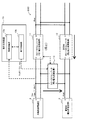
図1に示すように、本発明システム1は、負荷装置4に直流電力を供給する直流配電系統ESDと、直流配電系統ESDに太陽光発電装置2の発電電力を電圧変換して供給する第1電力変換装置11と、直流配電系統ESDに常時接続された電力貯蔵装置3と直流配電系統ESDとの間で電圧変換して、少なくとも電力貯蔵装置3側から直流配電系統ESD側へ電力供給する第2電力変換装置12と、電力貯蔵装置3に太陽光発電装置2の発電電力を電圧変換して供給する第3電力変換装置13を備えて構成されている。更に、本実施形態の本発明システム1は、交流系統ESAと直流配電系統ESDとの間で交流・直流間の電力変換を行い、一方側から他方側へ電力供給する第4電力変換装置14と、本発明システム1の動作設定を行う動作制御装置10を備えて構成されている。
As shown in FIG. 1, the
尚、本実施形態の本発明システム1では、交流系統ESAは商用交流電源(例えば、単相3線式200[V])に接続しており、第4電力変換装置14は、交流系統ESAと系統連系して逆潮流を可能に構成されている。交流系統ESAに交流電力を逆潮流させて供給すると、本発明システム1の利用者と電力会社との間の契約により、電力量に応じて電力会社が買い取る構成になっている。
In the
動作制御装置10は、直流配電系統ESDの電圧Vbus及び太陽光発電装置2の出力電圧Vpoの情報を取得する情報収集部10aと、第3電力変換装置13の運転開始及び運転停止の制御を行う動作制御部10bを備えて構成されている。本実施形態の情報収集部10aは、更に、負荷装置4に流れる電流の値、各電力変換装置に流れる電流の値、及び、電力貯蔵装置3の残量の情報等を取得するように構成されている。また、動作制御部10bは、第3電力変換装置13に対し、出力電圧の目標値Vdd3を設定するように構成されている。
The
太陽光発電装置2は、本実施形態では、図8に示す従来技術における太陽光発電装置111の構成と同じ構成であり、複数枚の太陽電池モジュールを直列に接続し、各太陽電池モジュールにダイオードを並列に接続して構成され、図9に示すIV特性を備えている。尚、本実施形態では、太陽光発電装置2が、複数枚の太陽電池モジュールを直列に接続して構成されている場合を想定しているが、これに限るものではない。例えば、複数枚の太陽電池モジュールを直列に接続した太陽電池ユニットが複数並列に接続される構成であっても良い。
In this embodiment, the solar
第1電力変換装置11は、本実施形態では、DC−DCコンバータ11で構成され、図8に示す従来技術におけるDC−DCコンバータ112の構成と同じ構成である。具体的には、DC−DCコンバータ11は、直流配電系統ESDの電圧Vbusが過電圧防止のために設定された定電圧運転開始電圧Vpv_max(例えば、400[V])より小さい場合は、太陽光発電装置2が最大電力を出力するようにMPPT制御を行い、電圧Vbusが定電圧運転開始電圧Vpv_maxより大きくなった場合は、MPPT制御を停止し、電圧Vbusが定電圧運転開始電圧Vpv_maxを超えないように出力電圧値が一定の値となるように動作する。
In the present embodiment, the first
更に、本発明システム1では、DC−DCコンバータ11及び後述するDC−DCコンバータ13が並列動作することから、DC−DCコンバータ11及びDC−DCコンバータ13が協働してMPPT制御できるように、DC−DCコンバータ11とDC−DCコンバータ13の間で、各DC−DCコンバータに流れる電流値等の情報を通信可能に構成されている。尚、MPPT制御を実現するための構成としては、これに限るものではなく、DC−DCコンバータ11及びDC−DCコンバータ13が太陽光発電装置2の出力電圧Vpoに加え出力電流を取得できる構成や、動作制御部10bによりDC−DCコンバータ11及びDC−DCコンバータ13の動作を制御する構成にしても良い。
Furthermore, in the
本実施形態では、DC−DCコンバータ11が動作可能な太陽光発電装置2の出力電圧Vpoの第1出力電圧範囲は、80[V]〜380[V]に設定されている。
In the present embodiment, the first output voltage range of the output voltage Vpo of the solar
尚、本実施形態では、第1電力変換装置11を1つのDC−DCコンバータ11で構成する場合について説明したが、複数のDC−DCコンバータを並列接続して構成しても良いし、他の構成であっても良い。
In addition, although this embodiment demonstrated the case where the 1st
蓄電池3は、本実施形態では、電力貯蔵装置3の一例であり、リチウムイオン電池で構成されている。尚、本実施形態ではリチウムイオン電池を例に説明するが、ナトリウム・硫黄電池等、他の電池であっても良い。蓄電池3は、後述する双方向DC−DCコンバータ12を介して直流配電系統ESDから供給される電力を充電し、充電した電力を双方向DC−DCコンバータ12を介して直流配電系統ESDに放電するように構成されている。更に、蓄電池3は、第3電力変換装置13を介して太陽光発電装置2から供給される電力を充電するように構成されている。
The
双方向DC−DCコンバータ12は、本実施形態では、第2電力変換装置12の一例であり、直流配電系統ESDの電圧に応じて、電力供給方向(充電または放電)、運転開始及び運転停止の制御を行う。双方向DC−DCコンバータ12は、充電動作時は、直流配電系統ESDからの電流を充電電流値Ichの充電電流に変換する、或いは、直流配電系統ESDの電圧Vbusを充電電圧値Vchの充電電圧に変換して、蓄電池3に電力を供給する。
In the present embodiment, the bidirectional DC-
より具体的には、双方向DC−DCコンバータ12は、充電動作時、蓄電池3の充電量が少なく、蓄電池3の電圧Vbatが充電電圧値Vchより低い場合は、直流配電系統ESDからの電流を充電電流値Ichの充電電流に変換して蓄電池3を充電する。そして、充電量が増加して双方向DC−DCコンバータ12の出力電圧(充電電圧)の値が充電電圧値Vchに達すると、満充電状態になるまで充電電圧の値を充電電圧値Vchに維持して充電を行う。満充電状態になり、蓄電池3の電圧Vbatが充電電圧値Vchになると、充電電流が0になり、充電が停止する。
More specifically, the bidirectional DC-
更に、双方向DC−DCコンバータ12は、放電動作時、蓄電池3の電圧Vbatを放電電圧値Vdchとなるように変換し、直流配電系統ESDへの電流が最大放電電流値Idch_maxを超えないように変換する。これにより、双方向DC−DCコンバータ12は、直流配電系統ESDの電圧Vbusの値が放電電圧値Vdchより小さい場合は、蓄電池3の貯蔵電力を直流配電系統ESDに供給する。
Furthermore, the bidirectional DC-
尚、本実施形態では、第2電力変換装置12が、1つの双方向DC−DCコンバータ12で構成される場合を想定して説明したが、充電用コンバータと放電用コンバータの2つのコンバータを備える構成、複数の双方向DC−DCコンバータが並列接続された構成等、他の構成であっても良い。
In the present embodiment, the second
第3電力変換装置13は、本実施形態では、DC−DCコンバータ13で構成されている。尚、本実施形態では、第3電力変換装置13が1つのDC−DCコンバータ13で構成される場合を想定して説明するが、複数のDC−DCコンバータが並列に接続される構成等、他の構成であっても良い。
The 3rd
第4電力変換装置14は、直流配電系統ESDの直流電力を商用交流電源と同じ電圧・周波数の交流電力に電力変換して交流系統ESAに供給するDC−ACインバータ14aと、交流系統ESAの交流電力を直流電力に電力変換して直流配電系統ESDに供給するAC−DCコンバータ10bで構成されており、直流配電系統ESDの電圧Vbusが一定の電圧値Vac(例えば、380[V])となるように、出力電流を制御する。本実施形態では、DC−ACインバータ14aは、直流配電系統ESDに接続する商用交流電源と系統連系する系統連系インバータとして機能する。
The
具体的には、直流配電系統ESDの電圧Vbusが増加して、DC−ACインバータ14aが運転を開始する直流配電系統ESDの電圧Vbusを規定する交流化開始電圧Vac_sより高くなると、DC−ACインバータ14aが、直流電源系統の直流電力を商用交流電源と同じ電圧・周波数の交流電力に電力変換して交流系統ESAに逆潮流させる。更に、直流配電系統ESDの電圧Vbusが増加した場合は、電流量を増加させる。更に、直流配電系統ESDの電圧Vbusが低下して、AC−DCコンバータ14bが運転を開始する直流配電系統ESDの電圧Vbusを規定する直流化開始電圧Vdc_sより低くなると、AC−DCコンバータ10bが、交流系統ESAの交流電力を直流電力に変換して直流配電系統ESDに供給する。尚、本実施形態のAC−DCコンバータ10bは、供給電力を制限するため、最大直流化電流値Iad_maxが設定されており、出力電流値が最大直流化電流値Iad_maxになると、出力電圧値が電圧値Vacより低下する。
Specifically, when the voltage Vbus of the DC power distribution system ESD increases and becomes higher than the AC conversion start voltage Vac_s that defines the voltage Vbus of the DC power distribution system ESD at which the DC-
尚、本実施形態では、第4電力変換装置14を、1つのDC−ACインバータ14aと1つのAC−DCコンバータ10bで構成したが、これに限るものではなく、例えば、DC−ACインバータ14aは、複数のDC−ACインバータを並列接続したものであっても良いし、AC−DCコンバータ10bは、複数のAC−DCコンバータを並列接続したものであっても良い。更に、第4電力変換装置14は、1つの双方向インバータで構成されていても良い。
In the present embodiment, the
負荷装置4は、本実施形態では、直流電力で動作する電気機器を想定している。例えば、テレビは、内部電源基板に、通常、高調波対策のための力率改善回路PFC(Power Factor Correction)が設置されており、力率改善回路PFCの出力電圧は直流電圧であるので、力率改善回路PFCを備えるテレビでは、力率改善回路PFCの出力側と直流配電系統ESDを接続することが可能である。同様に、交流電力を直流電力に変換して利用する家電製品では、直流電圧を直接利用するように構成可能であり、直流配電系統ESDに接続できる。 In the present embodiment, the load device 4 is assumed to be an electric device that operates with DC power. For example, in a TV, a power factor correction circuit PFC (Power Factor Correction) for countermeasures against harmonics is usually installed on an internal power supply board, and the output voltage of the power factor correction circuit PFC is a DC voltage. In a television provided with the rate improvement circuit PFC, it is possible to connect the output side of the power factor improvement circuit PFC and the DC distribution system ESD. Similarly, home appliances that use AC power converted to DC power can be configured to directly use DC voltage and can be connected to a DC distribution system ESD.
次に、本発明システム1の動作について図2〜図4を基に説明する。
Next, the operation of the
ここで、本実施形態では、太陽光発電装置2の発電電力が小さくDC−DCコンバータ11が停止する場合(DC−DCコンバータ11が停止する場合)、DC−DCコンバータ11が動作している場合であって、交流系統ESAへの電力供給が制限され、且つ、太陽光発電装置2の発電電力が負荷装置4の消費電力より大きい場合(DC−DCコンバータ11が動作している場合1)、DC−DCコンバータ11が動作している場合であって、太陽光発電装置2の発電電力が負荷装置4の消費電力以下の場合、または、交流系統ESAへの電力供給が制限されていない場合(DC−DCコンバータ11が動作している場合2)の3つの場合に分けて説明する。
Here, in this embodiment, when the generated power of the solar
〈DC−DCコンバータ11が停止する場合〉
太陽光発電装置2の出力電圧Vpoが第1出力電圧範囲の下限値より小さくなり、DC−DCコンバータ11が停止する場合について、図2及び図3を基に説明する。
<When DC-
The case where the output voltage Vpo of the solar
本発明システム1では、DC−DCコンバータ11が動作可能な太陽光発電装置2の出力電圧Vpoの第1出力電圧範囲(80[V]〜380[V])の下限値が、第3電力変換装置が動作可能な太陽光発電装置2の出力電圧Vpoの第2出力電圧範囲の下限値より高い場合を想定している。DC−DCコンバータ13は、太陽光発電装置2の出力電圧Vpoが第1出力電圧範囲内に設定された所定の第1閾値電圧Vth1以下になると動作を開始する。
In the
具体的には、第2出力電圧範囲は、20[V]〜380[V]に設定されている。また、第1閾値電圧Vth1は、DC−DCコンバータ11が安定動作できる太陽光発電装置2の出力電圧Vpoの範囲を考慮して設定されており、本実施形態では、100[V]に設定されている。
Specifically, the second output voltage range is set to 20 [V] to 380 [V]. Further, the first threshold voltage Vth1 is set in consideration of the range of the output voltage Vpo of the
動作制御部10bは、太陽光発電装置2の出力電圧Vpoに応じてDC−DCコンバータ13の運転開始及び運転停止の制御を行う(第1動作制御部)。具体的には、動作制御部10bは、太陽光発電装置2の出力電圧Vpoが低下して第1閾値電圧Vth1以下になると、DC−DCコンバータ13の運転を開始し、双方向DC−DCコンバータ12の動作(停止、充電動作、放電動作)に応じて、DC−DCコンバータ13の出力電圧の目標値Vdd3の設定を変更する。尚、DC−DCコンバータ11は、太陽光発電装置2の出力電圧Vpoが第1出力電圧範囲の下限値以下になると、入力電圧が低下して所望の出力電圧を得られない或いは正常に動作しないため、動作を停止する。
The
具体的には、双方向DC−DCコンバータ12が停止している場合、動作制御部10bは、DC−DCコンバータ13に対し、出力電圧の目標値Vdd3を蓄電池3の電圧Vbatより高い値に設定する。このように設定することにより、DC−DCコンバータ11が動作停止している場合でも、太陽光発電装置2の発電電力を蓄電池3に充電することができる。
Specifically, when the bidirectional DC-
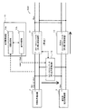
双方向DC−DCコンバータ12が充電動作を行っている場合、動作制御部10bは、図2に示すように、DC−DCコンバータ13に対し、出力電圧の目標値Vdd3を、双方向DC−DCコンバータ12に設定されている充電電圧の上限値Vch_maxより大きい値に設定する。このように設定することにより、太陽光発電装置2の発電電力が、直流配電系統ESDからの電力より優先して蓄電池3に充電される。尚、蓄電池3の残量が非常に少なく、蓄電池3の電圧Vbatが、DC−DCコンバータ13の出力電圧の目標値Vdd3より小さくなる場合は、太陽光発電装置2の発電電力と共に、双方向DC−DCコンバータ12により直流配電系統ESDの電力が蓄電池3に供給される。
When the bidirectional DC-
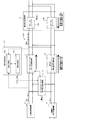
双方向DC−DCコンバータ12が放電動作を行っている場合、動作制御部10bは、図3に示すように、DC−DCコンバータ13に対し、出力電圧の目標値Vdd3を、蓄電池3の出力電圧Vbatより大きい値に設定する。このように設定することにより、太陽光発電装置2の発電電力が蓄電池3の貯蔵電力より優先して直流配電系統ESDに供給される。尚、負荷装置4の消費電力が大きく、直流配電系統ESDの電圧が低下して蓄電池3の出力側の電圧が電圧Vbatより低下する場合には、太陽光発電装置2の発電電力と共に、蓄電池3の電力も直流配電系統ESDに供給される。
When the bidirectional DC-
このように構成することにより、本発明システム1では、一部の太陽電池モジュールが発電不足に陥って太陽光発電装置2の発電電力が低下しDC−DCコンバータ11が停止した場合でも、DC−DCコンバータ13により太陽光発電装置2の発電電力を有効に利用できる。
By configuring in this way, in the
〈DC−DCコンバータ11が動作している場合1〉
DC−DCコンバータ11が動作している場合であって、交流系統ESAへの電力供給が制限され、且つ、太陽光発電装置2の発電電力が負荷装置4の消費電力より大きい場合について、図4を基に説明する。
<When DC-
FIG. 4 shows a case where the DC-
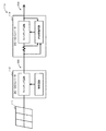
DC−DCコンバータ13は、図4に示すように、DC−DCコンバータ11が動作している場合であって、直流配電系統ESDの電圧Vbusが所定の第2閾値電圧Vth2以上の場合に動作するように構成されている。ここで、本実施形態では、第2閾値電圧Vth2は、DC−DCコンバータ11がMPPT制御を停止する定電圧運転開始電圧Vpv_maxを考慮して、定電圧運転開始電圧Vpv_max以下の値に設定されている。
As shown in FIG. 4, the DC-
動作制御部10bは、直流配電系統ESDの電圧に応じてDC−DCコンバータ13の運転開始及び運転停止の制御を行う(第2動作制御部)。具体的には、動作制御部10bは、直流配電系統ESDの電圧Vbusが第2閾値電圧Vth2以上になると、DC−DCコンバータ13の出力電圧の目標値Vdd3を蓄電池3の電圧Vbatより高い値に設定し、DC−DCコンバータ13の運転を開始する。
The
蓄電池3が満充電ではない場合は、DC−DCコンバータ13により、太陽光発電装置2の発電電力の一部が蓄電池3側に供給され、蓄電池3の充電動作が開始されるので、直流配電系統ESDへの電力供給が少なくなり、直流配電系統ESDの電圧Vbusの上昇を抑えることができるので、DC−DCコンバータ11は、MPPT制御を維持することが可能になる。
When the
蓄電池3が満充電の場合は、太陽光発電装置2の発電電力が全て直流配電系統ESDに供給されることになるので、直流配電系統の電圧Vbusは上昇する。直流配電系統ESDの電圧Vbusが定電圧運転開始電圧Vpv_maxを超えると、DC−DCコンバータ11は、MPPT制御を停止する。
When the
交流系統ESAへの電力供給が制限されている場合において、太陽光発電装置2の発電電力が負荷装置4の消費電力を上回り、直流配電系統ESDの電圧Vbusが過電圧防止のために設定された定電圧運転開始電圧Vpv_maxより上昇すると、DC−DCコンバータ11は、従来の太陽光発電システム100のDC−DCコンバータ112と同様に、MPPT制御を停止する。本発明システム1では、このような場合に、DC−DCコンバータ13により、太陽光発電装置2の発電電力を蓄電池3側に供給するので、直流配電系統ESDの電圧Vbusの上昇を抑えることができ、DC−DCコンバータ11がMPPT制御を維持できるので、太陽光発電装置2の発電電力をより有効に利用できる。
When the power supply to the AC system ESA is restricted, the generated power of the photovoltaic
〈DC−DCコンバータ11が動作している場合2〉
DC−DCコンバータ11が動作している場合であって、太陽光発電装置2の発電電力が負荷装置4の消費電力以下の場合、または、交流系統ESAへの電力供給が制限されていない場合、即ち、上述したDC−DCコンバータ11が停止する場合及びDC−DCコンバータ11が動作している場合1以外の場合について、図5及び図6を基に説明する。
<When DC-
When the DC-
動作制御部10bは、双方向DC−DCコンバータ12が放電動作を開始する直流配電系統ESDの電圧Vbusを規定する放電開始電圧Vdch_s、第2閾値電圧Vht2、及び、AC−DCコンバータ14bの直流化開始電圧Vdc_sを、Vth2>Vdch_s>Vdc_sとなるように設定する。また、双方向DC−DCコンバータ12の放電電圧値Vdchを第2閾値電圧Vth2より小さい値に設定する。更に、動作制御部10bは、DC−ACインバータ14aの交流化開始電圧Vac_sを、Vth2<Vac_s<Vpv_maxとなるように設定する。
The
以下、太陽光発電装置2の発電電力が負荷装置4の消費電力以下の場合と、負荷装置4の消費電力を上回る場合に分けて説明する。
Hereinafter, the case where the generated power of the solar
先ず、太陽光発電装置2の発電電力が負荷装置4の消費電力以下の場合について、図5を基に説明する。
First, the case where the generated power of the solar
例えば、負荷装置4の消費電力が相当大きい場合等、直流配電系統ESDの電圧Vbusが低下して双方向DC−DCコンバータ12の放電開始電圧Vdch_sを下回ると、蓄電池3の残量が空でない場合は、双方向DC−DCコンバータ12が放電動作を開始する。蓄電池3の残量が空の場合や負荷装置4の消費電力が相当大きく、直流配電系統ESDの電圧Vbusが更に低下して第4電力変換装置14の直流化開始電圧Vdc_sの設定値を下回った場合は、第4電力変換装置14のAC−DCコンバータ14bが交流系統ESAの電力を直流配電系統ESDに供給開始する。本実施形態では、双方向DC−DCコンバータ12の放電開始電圧Vdch_sの設定値を第4電力変換装置14の直流化開始電圧Vdc_sの設定値より大きい値に設定したので、蓄電池3の貯蔵電力が交流系統ESAの電力より優先的に直流配電系統ESDに供給される。
For example, when the power consumption of the load device 4 is considerably large, when the voltage Vbus of the DC distribution system ESD decreases and falls below the discharge start voltage Vdch_s of the bidirectional DC-
尚、ここでは、太陽光発電装置2の発電電力が負荷装置4の消費電力以下の場合を想定しているので、結果として、直流配電系統ESDの電圧Vbusは第2閾値電圧Vth2以下で維持される。これにより、DC−DCコンバータ11は、MPPT制御を維持できる。更に、ここでは、DC−DCコンバータ11が動作している場合、即ち、太陽光発電装置2の出力電圧Vpoが第1閾値電圧Vth1以上の場合を想定しているので、DC−DCコンバータ13は停止する。
Here, since it is assumed that the generated power of the solar
次に、太陽光発電装置2の発電電力が負荷装置4の消費電力より大きい場合について、図6を基に説明する。尚、交流系統ESAへの電力供給が制限されていないので、売電が可能である。
Next, the case where the generated power of the solar
直流配電系統ESDの電圧Vbusが上昇して第2閾値電圧Vth2より大きくなると、動作制御部10bは、DC−DCコンバータ13の出力電圧の目標値Vdd3を蓄電池3の電圧Vbatより大きく設定する。これにより、蓄電池3が満充電でない場合は、DC−DCコンバータ13により余った発電電力を蓄電池3へ充電することができ、直流配電系統ESDの電圧Vbusが上昇するのを抑えることができる。
When the voltage Vbus of the DC distribution system ESD increases and becomes greater than the second threshold voltage Vth2, the
蓄電池3が満充電の場合或いは負荷装置4の消費電力が少なくなる等して、更に直流配電系統ESDの電圧Vbusが上昇し、交流化開始電圧Vac_sより大きくなると、DC−ACインバータ14aが直流配電系統ESDの直流電力を電力変換して交流系統ESAに交流電力を供給し、売電を行う。これにより、直流配電系統ESDの電圧Vbusが定電圧運転開始電圧Vpv_max以下に維持され、DC−DCコンバータ11は、MPPT制御を維持することができる。
When the
尚、ここでは、動作制御部10bが、DC−ACインバータ14aの交流化開始電圧Vac_sを、Vth2<Vac_s<Vpv_maxとなるように設定し、売電より蓄電池への充電を優先して行う場合について説明したが、Vac_s<Vth2となるように設定して、蓄電池3への充電より売電を優先するように構成しても良い。この場合には、直流配電系統ESDの電圧Vbusが上昇して交流化開始電圧Vac_sに達した場合に、DC−ACインバータ14aが動作を開始して売電が行われ、直流配電系統ESDの電圧Vbusは交流化開始電圧Vac_sで維持され、結果として、第2閾値電圧Vth2を超えないので、DC−DCコンバータ13は動作しない。
Here, the case where the
〈別実施形態〉
〈1〉上記実施形態では、第2電力変換装置が、双方向DC−DCコンバータ12であり、蓄電池3側から直流配電系統ESD側への電力供給(放電)及び直流配電系統ESD側から蓄電池3側への電力供給(充電)を可能に構成されているが、これに限るものではなく、少なくとも蓄電池3側から直流配電系統ESD側へ電力供給するように構成されていれば良い。
<Another embodiment>
<1> In the above embodiment, the second power conversion device is the bidirectional DC-
〈2〉上記実施形態において、図1では図示していないが、交流系統ESAが、交流負荷に電力を供給するように構成されていても良い。 <2> In the above embodiment, although not shown in FIG. 1, the AC system ESA may be configured to supply power to the AC load.
〈3〉上記実施形態では、交流系統ESAと接続されている場合を想定して説明したが、これに限るものではなく、交流系統ESAと接続されず、第4電力変換装置14を備えていないシステムにも適用できる。
<3> In the above embodiment, the case where it is connected to the AC system ESA has been described. However, the present invention is not limited to this, and is not connected to the AC system ESA and does not include the
1 本発明に係る直流配電システム
2 太陽光発電装置
3 蓄電池(電力貯蔵装置)
4 負荷装置
10 動作制御装置
10a 情報収集部
10b 動作制御部
11 DC−DCコンバータ(第1電力変換装置)
12 双方向DC−DCコンバータ(第2電力変換装置)
13 DC−DCコンバータ(第3電力変換装置)
14 第4電力変換装置
14a DC−ACインバータ
14b AC−DCコンバータ
100 従来技術に係る直流配電システム
101 系統連系ユニット
102 電力貯蔵ユニット
103 フライホイールユニット
104 風力発電ユニット
105 太陽光発電ユニット
106 負荷ユニット
110 太陽光発電システム
111 太陽光発電装置
112 DC−DCコンバータ
113 DC−ACインバータ
ESD 直流配電系統
ESA 交流系統
DESCRIPTION OF
4
12 Bidirectional DC-DC converter (second power converter)
13 DC-DC converter (third power converter)
14
Claims (6)
前記直流配電系統に太陽光発電装置の発電電力を電圧変換して供給する第1電力変換装置と、
前記直流配電系統に常時接続された電力貯蔵装置と前記直流配電系統との間で電圧変換して、少なくとも前記電力貯蔵装置側から前記直流配電系統側へ電力供給する第2電力変換装置と、
を備えた直流配電システムであって、
前記電力貯蔵装置に前記太陽光発電装置の発電電力を電圧変換して供給する第3電力変換装置を備えることを特徴とする直流配電システム。 A DC distribution system for supplying DC power to the load device;
A first power converter that converts the voltage of the generated power of the solar power generator to supply to the DC distribution system;
A voltage conversion between the power storage device always connected to the DC power distribution system and the DC power distribution system, and at least a second power conversion device that supplies power from the power storage device side to the DC power distribution system side;
A DC power distribution system comprising:
A DC power distribution system comprising: a third power conversion device that converts the voltage of the power generated by the photovoltaic power generation device and supplies the generated power to the power storage device.
前記第3電力変換装置は、前記太陽光発電装置の出力電圧が前記第1出力電圧範囲内に設定された所定の第1閾値電圧以下になると動作を開始することを特徴とする請求項1に記載の直流配電システム。 The lower limit value of the first output voltage range of the output voltage of the photovoltaic power generator capable of operating the first power converter is the second of the output voltages of the photovoltaic power generator capable of operating the third power converter. Higher than the lower limit of the output voltage range,
The said 3rd power converter device starts operation | movement, when the output voltage of the said photovoltaic power generation device becomes below the predetermined | prescribed 1st threshold voltage set in the said 1st output voltage range. The described DC power distribution system.
前記第2電力変換装置が、前記直流配電系統側から前記電力貯蔵装置側へ電力供給可能に構成されていることを特徴とする請求項1〜5の何れか1項に記載の直流配電システム。 Comprising a fourth power conversion device for converting power between an AC system and the DC distribution system and supplying power from one side to the other;
The DC power distribution system according to any one of claims 1 to 5, wherein the second power conversion device is configured to be able to supply power from the DC power distribution system side to the power storage device side.
Priority Applications (1)
| Application Number | Priority Date | Filing Date | Title |
|---|---|---|---|
| JP2010145722A JP5541982B2 (en) | 2010-06-28 | 2010-06-28 | DC power distribution system |
Applications Claiming Priority (1)
| Application Number | Priority Date | Filing Date | Title |
|---|---|---|---|
| JP2010145722A JP5541982B2 (en) | 2010-06-28 | 2010-06-28 | DC power distribution system |
Publications (2)
| Publication Number | Publication Date |
|---|---|
| JP2012010531A JP2012010531A (en) | 2012-01-12 |
| JP5541982B2 true JP5541982B2 (en) | 2014-07-09 |
Family
ID=45540417
Family Applications (1)
| Application Number | Title | Priority Date | Filing Date |
|---|---|---|---|
| JP2010145722A Expired - Fee Related JP5541982B2 (en) | 2010-06-28 | 2010-06-28 | DC power distribution system |
Country Status (1)
| Country | Link |
|---|---|
| JP (1) | JP5541982B2 (en) |
Families Citing this family (10)
| Publication number | Priority date | Publication date | Assignee | Title |
|---|---|---|---|---|
| JP5738212B2 (en) * | 2012-02-20 | 2015-06-17 | 三菱重工業株式会社 | Power storage type power generation system |
| JP2013226027A (en) * | 2012-03-23 | 2013-10-31 | Sharp Corp | Power conditioner for storage battery and power supply system |
| JP5906153B2 (en) * | 2012-07-19 | 2016-04-20 | 株式会社デンソー | Charger |
| JP5981278B2 (en) * | 2012-09-07 | 2016-08-31 | 株式会社デンソー | In-vehicle power control device |
| JP5940946B2 (en) * | 2012-09-20 | 2016-06-29 | 京セラ株式会社 | Power conditioner and control method thereof |
| WO2015046594A1 (en) * | 2013-09-30 | 2015-04-02 | 日本電気株式会社 | Power supply circuit and power supply method |
| EP2933895B2 (en) * | 2014-04-14 | 2021-11-03 | AmbiBox GmbH | Control method and system with an inverter, a direct current source and a further direct current source or a direct current sink |
| JP6591230B2 (en) * | 2015-08-12 | 2019-10-16 | 株式会社Nttファシリティーズ | Photovoltaic power generation system control device, solar power generation system, and control program |
| JP6271638B2 (en) * | 2016-05-19 | 2018-01-31 | 京セラ株式会社 | Power conditioner and control method thereof |
| WO2018070037A1 (en) * | 2016-10-14 | 2018-04-19 | 東芝三菱電機産業システム株式会社 | Power conversion system, power supply system, and power conversion apparatus |
Family Cites Families (11)
| Publication number | Priority date | Publication date | Assignee | Title |
|---|---|---|---|---|
| JPH06106012B2 (en) * | 1986-06-11 | 1994-12-21 | 富士電機株式会社 | DC power supply system |
| JP3311419B2 (en) * | 1993-04-21 | 2002-08-05 | 三洋電機株式会社 | Solar power |
| JPH1023671A (en) * | 1996-07-03 | 1998-01-23 | Omron Corp | Power conditioner and dispersed power supplying system |
| JP3736205B2 (en) * | 1999-06-04 | 2006-01-18 | 三菱電機株式会社 | Battery power storage device |
| JP3781977B2 (en) * | 2001-03-09 | 2006-06-07 | 日本電信電話株式会社 | Distributed power supply network |
| JP2003009425A (en) * | 2001-06-26 | 2003-01-10 | Nippon Telegr & Teleph Corp <Ntt> | Power supply system and control method |
| JP2005070740A (en) * | 2003-03-20 | 2005-03-17 | Ryotaro Oshima | Advertisement information providing system using transparent organic el display device, advertisement information providing method using the same, and recording medium |
| JP4167215B2 (en) * | 2004-10-27 | 2008-10-15 | 株式会社日立製作所 | DC power distribution system control device and converter control device |
| JP5028049B2 (en) * | 2006-08-17 | 2012-09-19 | シャープ株式会社 | Solar power system |
| JP4561899B2 (en) * | 2008-08-01 | 2010-10-13 | パナソニック電工株式会社 | Power distribution system |
| EP2587623B1 (en) * | 2010-06-22 | 2016-06-29 | Sharp Kabushiki Kaisha | Dc power distribution system |
-
2010
- 2010-06-28 JP JP2010145722A patent/JP5541982B2/en not_active Expired - Fee Related
Also Published As
| Publication number | Publication date |
|---|---|
| JP2012010531A (en) | 2012-01-12 |
Similar Documents
| Publication | Publication Date | Title |
|---|---|---|
| JP5541982B2 (en) | DC power distribution system | |
| US8410634B2 (en) | Grid-connected power storage system and method for controlling grid-connected power storage system | |
| JP5028517B2 (en) | DC power supply system | |
| CN102170150B (en) | Power storage system | |
| JP6031759B2 (en) | Solar cell power generation system | |
| WO2011162025A1 (en) | Dc power distribution system | |
| WO2018127946A1 (en) | Uninterruptable power supply system, and uninterruptable power supply device | |
| CN102195312A (en) | A battery system | |
| JP5880778B2 (en) | Solar power system | |
| WO2015133136A1 (en) | Power source system | |
| AU2013206703A1 (en) | Power converter module, photovoltaic system with power converter module, and method for operating a photovoltaic system | |
| Mangu et al. | Multi-input transformer coupled DC-DC converter for PV-wind based stand-alone single-phase power generating system | |
| KR20150106694A (en) | Energy storage system and method for driving the same | |
| JP2012161189A (en) | Solar battery power charge and discharge control method to storage battery | |
| JP2015220889A (en) | Power supply system | |
| KR101764651B1 (en) | Power applying apparatus and method for controlling connecting photovoltaic power generating apparatus | |
| Wu et al. | Solar power generation system with power smoothing function | |
| Parsekar et al. | A novel strategy for battery placement in standalone solar photovoltaic converter system | |
| KR20150085227A (en) | The control device and method for Energy Storage System | |
| KR101587488B1 (en) | High efficiency battery charge/discharge system and method in grid-tied system | |
| Bhunia et al. | Voltage regulation of stand-alone photovoltaic system using boost SEPIC converter with battery storage system | |
| JP2014230366A (en) | Power generation device | |
| JP5810254B2 (en) | Power storage device | |
| Gawande et al. | Design and development of cost-effective solar PV based DC microgrid for rural applications | |
| Kusmantoro et al. | Voltage stability in DC micro grid by controlling two battery units with hybrid network systems |
Legal Events
| Date | Code | Title | Description |
|---|---|---|---|
| A621 | Written request for application examination |
Free format text: JAPANESE INTERMEDIATE CODE: A621 Effective date: 20130401 |
|
| A977 | Report on retrieval |
Free format text: JAPANESE INTERMEDIATE CODE: A971007 Effective date: 20140326 |
|
| TRDD | Decision of grant or rejection written | ||
| A01 | Written decision to grant a patent or to grant a registration (utility model) |
Free format text: JAPANESE INTERMEDIATE CODE: A01 Effective date: 20140408 |
|
| A61 | First payment of annual fees (during grant procedure) |
Free format text: JAPANESE INTERMEDIATE CODE: A61 Effective date: 20140502 |
|
| R150 | Certificate of patent or registration of utility model |
Ref document number: 5541982 Country of ref document: JP Free format text: JAPANESE INTERMEDIATE CODE: R150 |
|
| LAPS | Cancellation because of no payment of annual fees |