JP5882845B2 - Power storage type solar power generation system - Google Patents
Power storage type solar power generation system Download PDFInfo
- Publication number
- JP5882845B2 JP5882845B2 JP2012144103A JP2012144103A JP5882845B2 JP 5882845 B2 JP5882845 B2 JP 5882845B2 JP 2012144103 A JP2012144103 A JP 2012144103A JP 2012144103 A JP2012144103 A JP 2012144103A JP 5882845 B2 JP5882845 B2 JP 5882845B2
- Authority
- JP
- Japan
- Prior art keywords
- voltage
- power
- output terminal
- solar cell
- current
- Prior art date
- Legal status (The legal status is an assumption and is not a legal conclusion. Google has not performed a legal analysis and makes no representation as to the accuracy of the status listed.)
- Active
Links
- 238000010248 power generation Methods 0.000 title claims description 33
- 239000003990 capacitor Substances 0.000 claims description 30
- 230000007423 decrease Effects 0.000 claims description 12
- 238000006243 chemical reaction Methods 0.000 claims description 2
- 238000009499 grossing Methods 0.000 description 23
- 238000010586 diagram Methods 0.000 description 15
- 230000003247 decreasing effect Effects 0.000 description 6
- 238000001514 detection method Methods 0.000 description 5
- 230000005855 radiation Effects 0.000 description 2
- 238000007599 discharging Methods 0.000 description 1
- 230000005611 electricity Effects 0.000 description 1
- 238000012423 maintenance Methods 0.000 description 1
- 238000012986 modification Methods 0.000 description 1
- 230000004048 modification Effects 0.000 description 1
- 230000000630 rising effect Effects 0.000 description 1
Images


Classifications
-
- Y—GENERAL TAGGING OF NEW TECHNOLOGICAL DEVELOPMENTS; GENERAL TAGGING OF CROSS-SECTIONAL TECHNOLOGIES SPANNING OVER SEVERAL SECTIONS OF THE IPC; TECHNICAL SUBJECTS COVERED BY FORMER USPC CROSS-REFERENCE ART COLLECTIONS [XRACs] AND DIGESTS
- Y02—TECHNOLOGIES OR APPLICATIONS FOR MITIGATION OR ADAPTATION AGAINST CLIMATE CHANGE
- Y02E—REDUCTION OF GREENHOUSE GAS [GHG] EMISSIONS, RELATED TO ENERGY GENERATION, TRANSMISSION OR DISTRIBUTION
- Y02E10/00—Energy generation through renewable energy sources
- Y02E10/50—Photovoltaic [PV] energy
- Y02E10/56—Power conversion systems, e.g. maximum power point trackers
-
- Y—GENERAL TAGGING OF NEW TECHNOLOGICAL DEVELOPMENTS; GENERAL TAGGING OF CROSS-SECTIONAL TECHNOLOGIES SPANNING OVER SEVERAL SECTIONS OF THE IPC; TECHNICAL SUBJECTS COVERED BY FORMER USPC CROSS-REFERENCE ART COLLECTIONS [XRACs] AND DIGESTS
- Y02—TECHNOLOGIES OR APPLICATIONS FOR MITIGATION OR ADAPTATION AGAINST CLIMATE CHANGE
- Y02E—REDUCTION OF GREENHOUSE GAS [GHG] EMISSIONS, RELATED TO ENERGY GENERATION, TRANSMISSION OR DISTRIBUTION
- Y02E60/00—Enabling technologies; Technologies with a potential or indirect contribution to GHG emissions mitigation
- Y02E60/10—Energy storage using batteries
Description
この発明は電力貯蔵型太陽光発電システムに関し、特に、太陽電池で生成された直流電力のうちの余剰電力を電力貯蔵装置に蓄える直流変換器を備えた電力貯蔵型太陽光発電システムに関する。 This invention relates to a power storage type solar power generation system, in particular, to a power storage type photovoltaic power generation system provided with a DC converter for storing the excess power of the DC power generated by the solar cell to power storage device.
たとえば特許文献1には、夜間は、電力系統からの交流電力を直流電力に変換して蓄電池に蓄え、昼間は、太陽電池および蓄電池からの直流電力を交流電力に変換して負荷に供給する電力貯蔵型太陽光発電システムが開示されている。このシステムでは、余剰電力は、電力系統に逆潮流される。
For example, in
ところで、電力系統とは接続されず、太陽電池の余剰電力のみを蓄電池に蓄え、太陽電池および蓄電池からの直流電力を交流電力に変換して負荷に供給する電力貯蔵型太陽光発電システムも考えられる。 By the way, a power storage type solar power generation system that is not connected to the power system, stores only surplus power of the solar battery in the storage battery, converts the DC power from the solar battery and the storage battery into AC power, and supplies the power to the load is also conceivable. .
しかし、このようなシステムでは、太陽電池の余剰電力が過大になった場合、負荷に印加する電圧や蓄電池の端子間電圧が過大になり、負荷や蓄電池が破損するという問題がある。 However, in such a system, when the surplus power of the solar battery becomes excessive, the voltage applied to the load and the voltage between the terminals of the storage battery become excessive, and the load and the storage battery are damaged.
それゆえに、この発明の主たる目的は、直流負荷および電力貯蔵装置が破損することを防止することが可能な電力貯蔵型太陽光発電システムを提供することである。 Another object of the present invention is to provide a power storage type solar power generation system capable of preventing a DC load and the power storage device may be damaged.
この発明に係る電力貯蔵型太陽光発電システムは、太陽光のエネルギーを直流電力に変換する太陽電池と、直流電力を蓄える電力貯蔵装置と、太陽電池で生成された直流電力を直流負荷に供給するとともに余剰電力を電力貯蔵装置に蓄える直流変換器とを備えたものである。直流変換器は、直流負荷に接続される出力端子と、出力端子と基準電圧のラインとの間に接続されたコンデンサと、第1の電流指令値に応じた値の電流を太陽電池から出力端子に流す第1のDC/DCコンバータと、第2の電流指令値に応じた値の電流を出力端子と電力貯蔵装置の間に流す第2のDC/DCコンバータと、太陽電池の出力電圧および出力電流に基づいて最大電力点追従制御を行ない、太陽電池の出力電圧が最適動作電圧になるように第1の電流指令値を生成する第1の制御部と、出力端子の電圧が参照電圧になるように第2の電流指令値を生成する第2の制御部と、出力端子の電圧が参照電圧よりも高い第1の上限電圧を超えた場合に第1の電流指令値を減少させる第1の電圧制限部と、電力貯蔵装置の充電中において電力貯蔵装置の端子間電圧が参照電圧よりも低い第2の上限電圧を超えた場合に第2の電流指令値を減少させる第2の電圧制限部とを含む。この電力貯蔵型太陽光発電システムは、さらに、直流負荷として出力端子に接続され、直流変換器から直流電力を受けるとともに商用交流電源から商用交流電力を受け、出力端子の電圧が参照電圧よりも低い下限電圧よりも高い場合は、出力端子から受けた直流電力を交流電力に変換して交流負荷に供給し、出力端子の電圧が下限電圧よりも低い場合は、出力端子から受けた直流電力を交流電力に変換することを停止するとともに商用交流電源から受けた商用交流電力を交流負荷に与える交流電力供給装置を備えたものである。 A power storage solar power generation system according to the present invention supplies a solar cell that converts solar energy into DC power, a power storage device that stores DC power, and DC power generated by the solar cell to a DC load. And a DC converter for storing surplus power in the power storage device. The DC converter includes an output terminal connected to the DC load, a capacitor connected between the output terminal and the reference voltage line, and a current corresponding to the first current command value from the solar cell to the output terminal. A first DC / DC converter that flows through the second DC / DC converter, a second DC / DC converter that passes a current corresponding to the second current command value between the output terminal and the power storage device, and the output voltage and output of the solar cell The first control unit that performs the maximum power point tracking control based on the current and generates the first current command value so that the output voltage of the solar cell becomes the optimum operating voltage, and the voltage of the output terminal becomes the reference voltage The second control unit that generates the second current command value and the first control unit that decreases the first current command value when the voltage at the output terminal exceeds the first upper limit voltage that is higher than the reference voltage. Power during charging of voltage limiter and power storage device And a second voltage limiting unit to reduce the second current command value when the inter-terminal voltage of the built device exceeds the lower second upper limit voltage than the reference voltage. This power storage solar power generation system is further connected to an output terminal as a DC load, receives DC power from a DC converter and receives commercial AC power from a commercial AC power supply, and the voltage at the output terminal is lower than the reference voltage If the voltage is higher than the lower limit voltage, the DC power received from the output terminal is converted to AC power and supplied to the AC load. If the voltage at the output terminal is lower than the lower limit voltage, the DC power received from the output terminal is converted to AC. An AC power supply device that stops the conversion into electric power and supplies the AC load with the commercial AC power received from the commercial AC power supply is provided.
好ましくは、第2のDC/DCコンバータは、電力貯蔵装置の端子間電圧が出力端子の電圧よりも高い場合に、電力貯蔵装置から出力端子に電流を流すダイオードを含む。 Preferably, the second DC / DC converter includes a diode that causes a current to flow from the power storage device to the output terminal when the voltage between the terminals of the power storage device is higher than the voltage of the output terminal.
この発明に係る電力貯蔵型太陽光発電システムでは、直流変換器の出力端子の電圧が参照電圧よりも高い第1の上限電圧を超えた場合に第1の電流指令値を減少させる第1の電圧制限部と、電力貯蔵装置の充電中において電力貯蔵装置の端子間電圧が参照電圧よりも低い第2の上限電圧を超えた場合に第2の電流指令値を減少させる第2の電圧制限部とが設けられる。したがって、太陽電池の余剰電力が過剰になった場合でも、直流変換器の出力端子の電圧や電力貯蔵装置の端子間電圧が過大になるのを防止することができ、直流負荷および電力貯蔵装置が破損するのを防止することができる。
The engagement Ru electricity storage photovoltaic system to the present invention, the decrease of the first current command value when the voltage of the output terminal of the DC converter exceeds the higher first upper limit voltage than the
本願発明の一実施の形態による電力貯蔵型太陽光発電システムは、図1に示すように、太陽電池1、蓄電池2、DC(Direct Current:直流)変換器3、およびDC負荷11を備える。太陽電池1は、太陽光のエネルギーを直流電力に変換する。太陽電池1の発電量は、日射強度に応じて増大する。蓄電池2は、直流電力の充電および放電が可能な電池である。DC負荷11は、直流電力によって駆動される電気機器などである。
As shown in FIG. 1, a power storage solar power generation system according to an embodiment of the present invention includes a
DC変換器3は、太陽電池1の出力電圧VPVおよび出力電流IPVに基づいて最大電力点追従制御を行ない、太陽電池1の出力電圧VPVが最適動作電圧になるように太陽電池1からDC負荷11に電流を流す。また、DC変換器3は、出力電圧VDCが所定の参照電圧VDCR(たとえば、400V)よりも高い場合は太陽電池1からの直流電力を蓄電池2に供給し、出力電圧VDCが所定の参照電圧VDCRよりも低い場合は蓄電池2からの直流電力をDC負荷11に供給する。
The
また、DC変換器3は、出力電圧VDCを上限電圧VDCH(たとえば、500V)以下に制限するとともに、蓄電池2の端子間電圧VBを上限電圧VBH(たとえば、300V)以下に制限する。また、DC変換器3は、出力電圧VDCが蓄電池VBの端子間電圧VBよりも低い場合は、蓄電池2からDC負荷11に電流を流す。
詳しく説明すると、DC変換器3は、端子T1〜T3、電流センサ4,7、チョッパ5,8、制御部6,9、および平滑コンデンサ10を備える。端子T1〜T3は、それぞれ太陽電池1、蓄電池2、およびDC負荷11に接続される。平滑コンデンサ10は、端子T3と基準電圧(たとえば、接地電圧)のラインとの間に接続される。
More specifically, the
チョッパ5は、端子T1,T3間に接続されて制御部6によって制御され、太陽電池1で生成された直流電力を平滑コンデンサ10に供給する。電流センサ4は、太陽電池1からチョッパ5に流れる直流電流IPVを検出し、検出値を示す信号を制御部6に与える。
The
制御部6は、太陽電池1の端子間電圧VPVと平滑コンデンサ10の端子間電圧VDCを検出し、それらの検出値と電流センサ4の検出値とに基づいて、チョッパ5を制御する。制御部6は、太陽電池1の端子間電圧VPVが最適動作電圧VPVRになるようにチョッパ5を制御するとともに、平滑コンデンサ10の端子間電圧VDCが上限電圧VDCH以下になるようにチョッパ5を制御する。
The control unit 6 detects the inter-terminal voltage VPV of the
また、チョッパ8は、端子T1,T3間に接続されて制御部9によって制御され、平滑コンデンサ10から蓄電池2に直流電力を供給するか、逆に蓄電池2の直流電力を平滑コンデンサ10に供給する。電流センサ7は、チョッパ8と蓄電池2の間に流れる電流IBを検出し、検出値を示す信号を制御部9に与える。
The
制御部9は、蓄電池2の端子間電圧VBと平滑コンデンサ10の端子間電圧VDCを検出し、それらの検出値と電流センサ7の検出値とに基づいて、チョッパ8を制御する。制御部9は、平滑コンデンサ10の端子間電圧VDCが参照電圧VDCR(<VDCH)になるようにチョッパ8を制御するとともに、蓄電池2の端子間電圧VBが上限電圧VBH以下になるようにチョッパ8を制御する。
The
図2は、チョッパ5,8の構成を示す回路ブロック図である。図2において、チョッパ5は、コンデンサ21、インダクタ22、IGBT(Insulated Gate Bipolar Transistor:絶縁ゲート型バイポーラトランジスタ)23、およびダイオード24,25を含む。コンデンサ21は、端子T1と基準電圧のラインとの間に接続される。インダクタ22およびIGBT23は、端子T1と基準電圧のラインとの間に直列接続される。ダイオード24は、IGBT23に逆並列に接続される。ダイオード25のアノードはIGBT23のコレクタに接続され、そのカソードは端子T3に接続される。
FIG. 2 is a circuit block diagram showing the configuration of the
IGBT23は、制御部6によってPWM(pulse width modulation:パルス幅変調)制御され、所定の周期でオンおよびオフされる。IGBT23をオンさせると、太陽電池1からインダクタ22およびIGBT23を介して基準電圧のラインに電流が流れ、インダクタ22に電磁エネルギーが蓄えられる。IGBT23をオフさせると、インダクタ22に蓄えられた電磁エネルギーが放出され、インダクタ22からダイオード25を介して平滑コンデンサ10に電流が流れる。このとき、ダイオード25のアノードの電圧は、太陽電池1の端子間電圧VPVにインダクタ22の端子間電圧を加算した電圧となる。
The
つまり、チョッパ5は、太陽電池1の端子間電圧VPVを昇圧して平滑コンデンサ10に供給する。IGBT23のオン時間を長くすると平滑コンデンサ10の端子間電圧VDCの上昇速度が速くなり、IGBT23のオン時間を短くすると平滑コンデンサ10の端子間電圧VDCの上昇速度が遅くなる。
That is, the
また、チョッパ8は、コンデンサ31、インダクタ32、IGBT33、およびダイオード34,35を含む。コンデンサ31は、端子T2と基準電圧のラインとの間に接続される。IGBT33およびインダクタ32は、端子T3,T2間に直列接続される。ダイオード34は、IGBT33に逆並列に接続される。ダイオード35のアノードは基準電圧のラインに接続され、そのカソードはIGBT33のエミッタに接続される。
The
IGBT33は、制御部9によってPWM制御される。IGBT33は、VDC>VBである場合は、所定の周期でオンおよびオフされる。IGBT33をオンさせると、平滑コンデンサ10からIGBT33およびインダクタ32を介して蓄電池2に電流が流れ、インダクタ32に電磁エネルギーが蓄えられる。IGBT33をオフさせると、インダクタ32に蓄えられた電磁エネルギーが放出され、インダクタ32、蓄電池2、ダイオード35の経路に電流が流れる。このとき、蓄電池2の端子間電圧VBは、平滑コンデンサ10の端子間電圧VDCからインダクタ32の端子間電圧を減算した電圧になる。
The
つまり、チョッパ8は、平滑コンデンサ10の端子間電圧VDCを降圧して蓄電池2に供給する。IGBT33のオン時間を長くすると蓄電池2の端子間電圧VBの上昇速度が速くなり、IGBT33のオン時間を短くすると蓄電池2の端子間電圧VBの上昇速度が遅くなる。また、VDC<VBである場合は、IGBT33はオフ状態に固定され、蓄電池2からインダクタ32およびダイオード34を介して平滑コンデンサ10に直流電流が流れる。
That is, the
図3は、制御部6の構成を示す回路ブロック図である。図3において、制御部6は、MPPT(Maximum Power Point Tracking:最大電力点追従)制御器50、減算器51,53,58、電圧制御器52,54、リミッタ55、加算器57、電流制御器59、およびPWM制御器60を含む。
FIG. 3 is a circuit block diagram showing the configuration of the control unit 6. In FIG. 3, the control unit 6 includes an MPPT (Maximum Power Point Tracking)
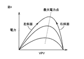
MPPT制御器50は、太陽電池1の最大電力点追従制御を行ない、太陽電池1の出力電圧VPVおよび出力電流IPVに基づいて、太陽電池1の出力が最大になる最適動作電圧を求め、参照電圧VPVRをその最適動作電圧に設定する。図4は、太陽電池1の最大電力点追従制御を説明するための図である。図4において、太陽電池1においては、出力電流IPVが増加すると端子間電圧VPVが低下するという特性があり、太陽電池1の出力は端子間電圧VPVに応じてなだらかな山状の曲線に沿って変化する。太陽電池1の出力が最大になる点は最大電力点と呼ばれ、そのときの太陽電池1の端子間電圧VPVは最適動作電圧と呼ばれる。
The
換言すると、太陽電池1の端子間電圧VPVが最適動作電圧に一致するように電流IPVを取り出すと、太陽電池1から最大電力を取り出すことができる。日射強度が変化すると、最大電力点および最適動作電圧も変化する。このため、MPPT制御器50は、太陽電池1の出力電圧VPVおよび出力電流IPVに基づいて、最適動作電圧に一致するように参照電圧VPVRを調整する。
In other words, the maximum power can be extracted from the
具体的に説明すると、MPPT制御器50は、所定周期で参照電圧VPVRを微小電圧ΔVだけ増加および減少させ、太陽電池1の出力が増加する方向に参照電圧VPVRをΔVだけ変化させる。ΔVだけ増加させた場合に太陽電池1の出力が増加し、ΔVだけ減少させた場合に太陽電池1の出力が減少した場合は、VPVが図4の曲線の左斜面に位置しているので、参照電圧VPVRをΔVだけ増加させる。また、ΔVだけ増加させた場合に太陽電池1の出力が減少し、ΔVだけ減少させた場合に太陽電池1の出力が増加した場合は、VPVが図4の曲線の右斜面に位置しているので、参照電圧VPVRをΔVだけ減少させる。
Specifically, the
図3に戻って、減算器51は、太陽電池1の出力電圧VPVの検出値からMPPT制御器50で生成された参照電圧VPVRを減算し、減算結果VPV−VPVRを示す信号を電圧制御器52に与える。電圧制御器52は、VPV−VPVRを0にするための電流指令値を生成し、その電流指令値を加算器57に与える。
Returning to FIG. 3, the
また、減算器53は、上限電圧VDCH(たとえば、500V)から平滑コンデンサ10の端子間電圧VDCを減算し、その減算結果VDCH−VDCを示す信号を電圧制御器54に与える。電圧制御器54は、VDCH-VDCを0にするための電流指令値を生成し、その電流指令値をリミッタ55に与える。リミッタ55は、電圧制御器54からの電流指令値が負の場合はその電流指令値を通過させ、電圧制御器54からの電流指令値が正の場合はその電流指令値を0に設定する。減算器53、電圧制御器54、およびリミッタ55は、平滑コンデンサ10の端子間電圧VDCを上限電圧VDCH以下の電圧に制限する電圧制限部56を構成する。
VDC<VDCHである場合は、電圧制限部56から出力される電流指令値の値は0になる。また、VDC>VDCHである場合は、電圧制限部56から出力される電流指令値はVDC−VDCHに応じた値となる。
When VDC <VDCH, the value of the current command value output from the
加算器57は、電圧制御器52からの電流指令値と電圧制限部56からの電流指令値とを加算して参照電流値IPVRを生成する。減算器58は、参照電流値IPVRから太陽電池1の出力電流IPVの検出値を減算し、その減算結果IPVR−IPVを示す信号を電流制御器59に与える。電流制御器59は、減算器58で求められた電流IPVR−IPVを流すための電流指令値を生成する。PWM制御器60は、電流制御器59からの電流指令値に応じた値の電流が太陽電池1からDC負荷11に流れるようにチョッパ5を制御する。チョッパ5およびPWM制御器60は、第1のDC/DCコンバータを構成する。これにより、DC変換器3の出力電圧VDCは、上限電圧VDCH以下に制限される。
The
図5は、制御部9の構成を示す回路ブロック図である。図5において、制御部9は、減算器61,66,70、電圧制御器62,67、リミッタ63,68、加算器65、電流制御器71、およびPWM制御器72を含む。
FIG. 5 is a circuit block diagram showing the configuration of the
減算器61は、平滑コンデンサ10の端子間電圧VDCから参照電圧VDCR(たとえば、400V)を減算し、その減算結果VDC−VDCRを示す信号を電圧制御器62に与える。参照電圧VDCRは、上限電圧VDCHよりも低い電圧に設定される。電圧制御器62は、VDCR−VDCを0にするための電流指令値を生成し、その電流指令値をリミッタ63に与える。
The
リミッタ63は、電圧制御器62からの電流指令値が正の上限値と負の下限値との間の値である場合はその電流指令値を通過させる。また、リミッタ63は、電圧制御器62からの電流指令値が正の上限値よりも正側にある場合は、その電流指令値を正の上限値に設定する。また、リミッタ63は、電圧制御器62からの電流指令値が負の下限値よりも負側にある場合は、その電流指令値を負の下限値に設定する。減算器61、電圧制御器62、およびリミッタ63は、平滑コンデンサ10の端子間電圧VDCを一定電圧VDCRに制御する電圧制御部64を構成する。
When the current command value from the
また、減算器66は、上限電圧VBH(たとえば、300V)から蓄電池2の端子間電圧VBを減算し、その減算結果VBH−VBを示す信号を電圧制御器67に与える。電圧制御器67は、VBH−VBを0にするための電流指令値を生成し、その電流指令値をリミッタ68に与える。リミッタ68は、電圧制御器67からの電流指令値が負の場合はその電流指令値を通過させ、電圧制御器54からの電流指令値が正の場合はその電流指令値を0に設定する。減算器53、電圧制御器67、およびリミッタ68は、蓄電池2の端子間電圧VBを上限電圧VBH以下の電圧に制限する電圧制限部69を構成する。
VB<VBHである場合は、電圧制限部69から出力される電流指令値の値は0になる。また、VB>VBHである場合は、電圧制限部69から出力される電流指令値はVB−VBHに応じた値となる。
When VB <VBH, the value of the current command value output from the
加算器65は、電圧制御部64からの電流指令値と電圧制限部69からの電流指令値とを加算して参照電流値IBRを生成する。減算器70は、参照電流値IBRから蓄電池2の充電電流IBの検出値を減算し、その減算結果IBR−IBを示す信号を電流制御器71に与える。電流制御器71は、減算器70で求められた電流IBR−IBを流すための電流指令値を生成する。PWM制御器72は、電流制御器71からの電流指令値に応じた値の電流が平滑コンデンサ10と蓄電池2との間に流れるようにチョッパ8を制御する。チョッパ8およびPWM制御器71は、第2のDC/DCコンバータを構成する。
The
図6は、図1〜図5に示した電力貯蔵型太陽光発電システムの動作を示す回路ブロック図である。図6では、太陽電池1と端子T1の間にブレーカB1が接続され、蓄電池2と端子T2の間にブレーカB2が接続されている。ブレーカB1は、太陽電池1の交換時などにオフされ、通常はオンされる。ブレーカB2は、蓄電池2の交換時などにオフされ、通常はオンされる。
FIG. 6 is a circuit block diagram showing an operation of the power storage type solar power generation system shown in FIGS. In FIG. 6, the breaker B1 is connected between the
また、端子T1とチョッパ5の入力端子との間にスイッチS1が接続され、端子T2とチョッパ8の入力端子との間にスイッチS2が接続される。スイッチS1,S2は、DC変換器3の停止時にオフされ、DC変換器3の運転時にオンされる。
Further, the switch S1 is connected between the terminal T1 and the input terminal of the
DC負荷11としてUPS(Uninterruptible Power Supply:無停電電源装置)81が使用される。端子T3とUPS81の直流端子81aとの間にブレーカB3が接続される。ブレーカB3は、UPS81の交換時などにオフされ、通常はオンされる。UPS81の交流端子81bは商用交流電源80に接続され、出力端子81cはAC(alternating current:交流)負荷82に接続される。
As the
UPS81は、たとえば、交流電力を直流電力に変換するインバータと、端子81b,81c間に接続されたスイッチと、直流端子81aの電圧を検出する電圧検出器と、電圧検出器の検出結果に基づいてインバータおよびスイッチを制御する制御部とを含む。
The
UPS81は、DC変換器3の出力電圧VDCが下限電圧VDCL(たとえば、200V)よりも高い場合は、DC変換器3からの直流電力を商用周波数の交流電力に変換してAC負荷82に供給する。下限電圧VDCLは、参照電圧VDCRよりも低い電圧に設定される。また、USP81は、DC変換器3の出力電圧VDCが下限電圧VDCLよりも低い場合は、DC変換器3からの直流電力を商用周波数の交流電力に変換することを停止し、商用交流電源80からの交流電力をAC負荷82に供給する。
When the output voltage VDC of the
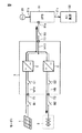
この電力貯蔵型太陽光発電システムは、太陽電池1の発電量などに応じて、6つのモードのうちのいずれかのモードで動作する。太陽電池1の発電量がUPS81が必要とする電力量よりも大きい場合、図6で示すように、発電システムはモード1で動作する。モード1では、太陽電池1で生成された直流電力がチョッパ5によってUPS81に供給されるとともに、余剰電力がチョッパ8によって蓄電池2に供給される。UPS81は、DC変換器3からの直流電力を交流電力に変換してAC負荷82に供給する。余剰電力は、蓄電池2に蓄えられる。
This power storage solar power generation system operates in one of six modes depending on the amount of power generated by the
このとき、太陽電池1の出力電圧VPVは最適動作電圧に設定され、太陽電池1からチョッパ5を介してUPS81に電流が流される。また、DC変換器3の出力電圧VDCが参照電圧VDCRになるように、出力端子T3からチョッパ8を介して蓄電池2に電流が流される。たとえば晴天が続いて、蓄電池2の端子間電圧VBが上限電圧VBHに到達した場合は、チョッパ8の運転が停止され、蓄電池2の充電が停止される。さらに、たとえばAC負荷82における消費電力が低下して余剰電力が増大し、DC変換器3の出力電圧VDCが上限電圧VDCHに到達した場合は、チョッパ5に流れる電流が低減される。
At this time, the output voltage VPV of the
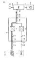
また、太陽電池1の発電量がUPS81が必要とする電力量よりも小さい場合、図7に示すように、発電システムはモード2で動作する。モード2では、太陽電池1で生成された直流電力がチョッパ5によってUPS81に供給されるとともに、蓄電池2の直流電力がチョッパ8によってUPS81に供給される。UPS81は、DC変換器3からの直流電力を交流電力に変換してAC負荷82に供給する。
When the power generation amount of the
このとき、太陽電池1の出力電圧VPVは最適動作電圧に設定され、太陽電池1からチョッパ5を介してUPS81に電流が流される。また、DC変換器3の出力電圧VDCが参照電圧VDCRになるように、蓄電池2からチョッパ8を介して出力端子T3に電流が流される。
At this time, the output voltage VPV of the
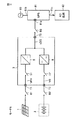
また、たとえば夜になって、太陽電池1の発電量が0になった場合、図8に示すように、発電システムはモード3で動作する。モード3では、チョッパ5の運転は停止され、蓄電池2の直流電力がチョッパ8によってUPS81に供給される。UPS81は、DC変換器3からの直流電力を交流電力に変換してAC負荷82に供給する。
For example, when the amount of power generated by the
このとき、DC変換器3の出力電圧VDCが参照電圧VDCRになるように、蓄電池2からチョッパ8を介して出力端子T3に電流が流される。DC変換器3の出力電圧VDCが低下して下限電圧VDCLよりも低下した場合、UPS81は、DC変換器3からの直流電力を交流電力に変換することを停止し、商用交流電源80からの交流電力をAC負荷82に供給する。なお、蓄電池2の端子間電圧VBが下限電圧VBLになった場合は、蓄電池2の過放電を防止するために蓄電池2の放電が停止される。
At this time, a current flows from the
また、太陽電池1の発電量がUPS81が必要とする電力量よりも大きいが、たとえば蓄電池2のメンテナンスを行なうために蓄電池2が端子T2から切り離されている場合、図9に示すように、発電システムはモード4で動作する。モード4では、チョッパ8の運転は停止され、太陽電池1で生成された直流電力がチョッパ5によってUPS81に供給される。UPS81は、DC変換器3からの直流電力を交流電力に変換してAC負荷82に供給する。
Further, when the power generation amount of the
このとき、太陽電池1の出力電圧VPVは最適動作電圧に設定され、太陽電池1からチョッパ5を介してUPS81に電流が流される。また、たとえばAC負荷82における消費電力が低下して余剰電力が増大し、DC変換器3の出力電圧VDCが上限電圧VDCHに到達した場合は、VDCが一定の電圧VDCHになるようにチョッパ5が制御される。
At this time, the output voltage VPV of the
また、太陽電池1の発電量がUPS81が必要とする電力量よりも小さく、DC変換器3の出力電圧VDCが下限電圧VDCLよりも低下し、DC変換器3からUPS81への電力供給が停止した場合、図10に示すように、発電システムはモード5で動作する。モード5では、太陽電池1で生成された直流電力がチョッパ5,8によって蓄電池8に供給される。
Further, the amount of power generated by the
このとき、太陽電池1の出力電圧VPVは最適動作電圧に設定され、太陽電池1からチョッパ5を介してチョッパ8に電流が流される。また、DC変換器3の出力電圧VDCが参照電圧VDCRになるように、出力端子T3からチョッパ8を介して蓄電池2に電流が流される。
At this time, the output voltage VPV of the
また、太陽電池1の発電量が0であり、蓄電池2の放電もできない場合は、図11に示すように、発電システムはモード6に設定される。モード6では、チョッパ5,8の運転は停止される。
Further, when the power generation amount of the
なお、チョッパ5が故障した場合、発電システムはモード3またはモード6に設定される。また、チョッパ8が故障した場合、発電システムはモード4またはモード6に設定される。また、起動前にDC変換器3が重故障して停止している場合、発電システムはモード6に設定される。
When the
この実施の形態では、DC変換器3の出力電圧VDCが上昇して上限電圧VDCHを超えた場合は、太陽電池1からチョッパ5を介して出力端子T3に流れる電流を減少させる。また、蓄電池2の端子間電圧VBが上限電圧VBHを超えた場合は、出力端子T3からチョッパ8を介して蓄電池2に流れる電流を減少させる。したがって、太陽電池1の余剰電力が過剰になった場合でも、出力端子T3の電圧VDCや蓄電池2の端子間電圧VBが過大になるのを防止することができ、DC負荷11および蓄電池2が破損するのを防止することができる。
In this embodiment, when the output voltage VDC of the
今回開示された実施の形態はすべての点で例示であって制限的なものではないと考えられるべきである。本発明の範囲は上記した説明ではなくて特許請求の範囲によって示され、特許請求の範囲と均等の意味および範囲内でのすべての変更が含まれることが意図される。 The embodiment disclosed this time should be considered as illustrative in all points and not restrictive. The scope of the present invention is defined by the terms of the claims, rather than the description above, and is intended to include any modifications within the scope and meaning equivalent to the terms of the claims.
1 太陽電池、2 蓄電池、3 DC変換器、T1〜T3 端子、4,7 電流センサ、5,8 チョッパ、6,9 制御部、10 平滑コンデンサ、11 DC負荷、21,31 コンデンサ、22,32 インダクタ、23,33 IGBT、24,25,34,35 ダイオード、50 MPPT制御器、51,53,58,61,66,70 減算器、52,54,62,67 電圧制御器、55,63,68 リミッタ、56,69 電圧制限部、57,65 加算器、59,71 電流制御器、60,72 PWM制御器、64 電圧制御部、80 商用交流電源、81 UPS、82 AC負荷。
DESCRIPTION OF
Claims (2)
直流電力を蓄える電力貯蔵装置と、
前記太陽電池で生成された直流電力を直流負荷に供給するとともに余剰電力を前記電力貯蔵装置に蓄える直流変換器とを備え、
前記直流変換器は、
前記直流負荷に接続される出力端子と、
前記出力端子と基準電圧のラインとの間に接続されたコンデンサと、
第1の電流指令値に応じた値の電流を前記太陽電池から前記出力端子に流す第1のDC/DCコンバータと、
第2の電流指令値に応じた値の電流を前記出力端子と前記電力貯蔵装置の間に流す第2のDC/DCコンバータと、
前記太陽電池の出力電圧および出力電流に基づいて最大電力点追従制御を行ない、前記太陽電池の出力電圧が最適動作電圧になるように前記第1の電流指令値を生成する第1の制御部と、
前記出力端子の電圧が参照電圧になるように前記第2の電流指令値を生成する第2の制御部と、
前記出力端子の電圧が前記参照電圧よりも高い第1の上限電圧を超えた場合に前記第1の電流指令値を減少させる第1の電圧制限部と、
前記電力貯蔵装置の充電中において前記電力貯蔵装置の端子間電圧が前記参照電圧よりも低い第2の上限電圧を超えた場合に前記第2の電流指令値を減少させる第2の電圧制限部とを含み、
さらに、前記直流負荷として前記出力端子に接続され、前記直流変換器から直流電力を受けるとともに商用交流電源から商用交流電力を受け、前記出力端子の電圧が前記参照電圧よりも低い下限電圧よりも高い場合は、前記出力端子から受けた直流電力を交流電力に変換して交流負荷に供給し、前記出力端子の電圧が前記下限電圧よりも低い場合は、前記出力端子から受けた直流電力を交流電力に変換することを停止するとともに前記商用交流電源から受けた商用交流電力を前記交流負荷に与える交流電力供給装置を備える、電力貯蔵型太陽光発電システム。 A solar cell that converts solar energy into DC power;
A power storage device for storing DC power;
A DC converter for supplying DC power generated by the solar cell to a DC load and storing surplus power in the power storage device;
The DC converter is
An output terminal connected to said DC load,
A capacitor connected between the output terminal and a reference voltage line;
A first DC / DC converter supplying a current of a value corresponding to the first current command value to said output terminal from said solar cell,
A second DC / DC converter to flow between said output terminal and said power storage device current of a value corresponding to the second current command value,
A first controller that performs maximum power point tracking control based on the output voltage and output current of the solar cell, and generates the first current command value so that the output voltage of the solar cell becomes an optimum operating voltage; ,
A second control unit that generates the second current command value so that the voltage of the output terminal becomes a reference voltage;
A first voltage limiter that decreases the first current command value when the voltage at the output terminal exceeds a first upper limit voltage that is higher than the reference voltage;
A second voltage limiter configured to decrease the second current command value when a voltage between terminals of the power storage device exceeds a second upper limit voltage lower than the reference voltage during charging of the power storage device; Including
Further, the DC load is connected to the output terminal, receives DC power from the DC converter and receives commercial AC power from a commercial AC power supply, and the voltage at the output terminal is higher than a lower limit voltage lower than the reference voltage. In the case, the DC power received from the output terminal is converted into AC power and supplied to an AC load. When the voltage at the output terminal is lower than the lower limit voltage, the DC power received from the output terminal A power storage solar power generation system including an AC power supply device that stops the conversion into the AC and supplies the AC load with the commercial AC power received from the commercial AC power source .
Priority Applications (1)
| Application Number | Priority Date | Filing Date | Title |
|---|---|---|---|
| JP2012144103A JP5882845B2 (en) | 2012-06-27 | 2012-06-27 | Power storage type solar power generation system |
Applications Claiming Priority (1)
| Application Number | Priority Date | Filing Date | Title |
|---|---|---|---|
| JP2012144103A JP5882845B2 (en) | 2012-06-27 | 2012-06-27 | Power storage type solar power generation system |
Publications (2)
| Publication Number | Publication Date |
|---|---|
| JP2014007929A JP2014007929A (en) | 2014-01-16 |
| JP5882845B2 true JP5882845B2 (en) | 2016-03-09 |
Family
ID=50105204
Family Applications (1)
| Application Number | Title | Priority Date | Filing Date |
|---|---|---|---|
| JP2012144103A Active JP5882845B2 (en) | 2012-06-27 | 2012-06-27 | Power storage type solar power generation system |
Country Status (1)
| Country | Link |
|---|---|
| JP (1) | JP5882845B2 (en) |
Families Citing this family (12)
| Publication number | Priority date | Publication date | Assignee | Title |
|---|---|---|---|---|
| JP6295782B2 (en) * | 2014-03-31 | 2018-03-20 | 株式会社安川電機 | Power conversion device, power generation system, control device, and power conversion method |
| KR102396138B1 (en) * | 2014-07-22 | 2022-05-10 | 셔랫, 리처드 | Dc energy transfer apparatus, applications, components, and methods |
| WO2016157874A1 (en) * | 2015-03-27 | 2016-10-06 | 京セラ株式会社 | Power supply device control method, power supply device, and power supply system |
| JP7228949B2 (en) * | 2016-07-26 | 2023-02-27 | 山洋電気株式会社 | power converter |
| WO2018058351A1 (en) * | 2016-09-28 | 2018-04-05 | Abb Schweiz Ag | Control system and photovoltaic system and micro-grid using the same and method thereof |
| CN110121825B (en) * | 2017-01-04 | 2022-08-09 | 东芝三菱电机产业系统株式会社 | Uninterruptible power supply system and uninterruptible power supply device |
| JP6787804B2 (en) * | 2017-01-31 | 2020-11-18 | ニチコン株式会社 | A power converter and a power supply system equipped with the power converter |
| WO2018142579A1 (en) * | 2017-02-03 | 2018-08-09 | 東芝三菱電機産業システム株式会社 | Uninterruptible power supply device |
| JP2018137849A (en) * | 2017-02-20 | 2018-08-30 | 株式会社ジェットシステム | Control device for power supply, and power supply |
| JP7020824B2 (en) * | 2017-09-01 | 2022-02-16 | 株式会社Rej | Battery converter and three-phase power storage system |
| US10931116B2 (en) * | 2018-03-29 | 2021-02-23 | Astec International Limited | Priority load sharing for electrical power systems having multiple power sources |
| JP7417088B2 (en) | 2020-03-23 | 2024-01-18 | 日新電機株式会社 | Control device and output control device |
Family Cites Families (6)
| Publication number | Priority date | Publication date | Assignee | Title |
|---|---|---|---|---|
| JP2002369406A (en) * | 2001-06-08 | 2002-12-20 | Hitachi Ltd | System-interconnected power system |
| JP2008154334A (en) * | 2006-12-15 | 2008-07-03 | Matsushita Electric Ind Co Ltd | Power conditioner |
| KR101156533B1 (en) * | 2009-12-23 | 2012-07-03 | 삼성에스디아이 주식회사 | Energy storage system and method for controlling thereof |
| EP2587623B1 (en) * | 2010-06-22 | 2016-06-29 | Sharp Kabushiki Kaisha | Dc power distribution system |
| JP5028517B2 (en) * | 2010-10-26 | 2012-09-19 | シャープ株式会社 | DC power supply system |
| KR101243909B1 (en) * | 2010-12-16 | 2013-03-14 | 삼성에스디아이 주식회사 | System for energy storage and control method thereof |
-
2012
- 2012-06-27 JP JP2012144103A patent/JP5882845B2/en active Active
Also Published As
| Publication number | Publication date |
|---|---|
| JP2014007929A (en) | 2014-01-16 |
Similar Documents
| Publication | Publication Date | Title |
|---|---|---|
| JP5882845B2 (en) | Power storage type solar power generation system | |
| US10811900B2 (en) | Uninterruptible power supply system and uninterruptible power supply apparatus | |
| US10084315B2 (en) | Power conversion device with an autonomous operation function | |
| JP5641144B2 (en) | Power converter | |
| JP5903622B2 (en) | Power supply system and charge / discharge power conditioner | |
| EP2991183B1 (en) | Charging and discharging system and method, and photovoltaic power generation system | |
| JP5541982B2 (en) | DC power distribution system | |
| US20120228942A1 (en) | Electric power generation system, method of controlling a battery, computer-readable recording medium which records a control programs and device controlling a battery | |
| JP6455661B2 (en) | Independent operation system | |
| JP2013161139A (en) | Power supply system and power supply device | |
| JP7228949B2 (en) | power converter | |
| US20120228935A1 (en) | Electric power generation system, method of controlling a battery and computer-readable recording medium | |
| JP2014099986A (en) | Composite power storage system | |
| JP2013021792A (en) | Power supply system | |
| JP2012161189A (en) | Solar battery power charge and discharge control method to storage battery | |
| JP2005269843A (en) | Parallel operation device | |
| KR101570866B1 (en) | battery charging system of solar module | |
| JP5480343B2 (en) | DC power supply system | |
| JP2015065765A (en) | Charging circuit and charging system | |
| JP6225672B2 (en) | Power supply equipment and operation method thereof | |
| JP2014230366A (en) | Power generation device | |
| JP5810254B2 (en) | Power storage device | |
| JP2021027749A (en) | Charge/discharge control device, battery including the same, and dc power supply system | |
| Uppuluri et al. | A Comprehensive SoC-based Energy Management of a PV-BESS Microgrid | |
| JP2017158265A (en) | Electric power supply system and electric power conversion system |
Legal Events
| Date | Code | Title | Description |
|---|---|---|---|
| A621 | Written request for application examination |
Free format text: JAPANESE INTERMEDIATE CODE: A621 Effective date: 20141021 |
|
| A977 | Report on retrieval |
Free format text: JAPANESE INTERMEDIATE CODE: A971007 Effective date: 20150610 |
|
| A131 | Notification of reasons for refusal |
Free format text: JAPANESE INTERMEDIATE CODE: A131 Effective date: 20150630 |
|
| A521 | Request for written amendment filed |
Free format text: JAPANESE INTERMEDIATE CODE: A523 Effective date: 20150811 |
|
| TRDD | Decision of grant or rejection written | ||
| A01 | Written decision to grant a patent or to grant a registration (utility model) |
Free format text: JAPANESE INTERMEDIATE CODE: A01 Effective date: 20160202 |
|
| A61 | First payment of annual fees (during grant procedure) |
Free format text: JAPANESE INTERMEDIATE CODE: A61 Effective date: 20160204 |
|
| R150 | Certificate of patent or registration of utility model |
Ref document number: 5882845 Country of ref document: JP Free format text: JAPANESE INTERMEDIATE CODE: R150 |
|
| R250 | Receipt of annual fees |
Free format text: JAPANESE INTERMEDIATE CODE: R250 |
|
| R250 | Receipt of annual fees |
Free format text: JAPANESE INTERMEDIATE CODE: R250 |
|
| R250 | Receipt of annual fees |
Free format text: JAPANESE INTERMEDIATE CODE: R250 |
|
| R250 | Receipt of annual fees |
Free format text: JAPANESE INTERMEDIATE CODE: R250 |
|
| R250 | Receipt of annual fees |
Free format text: JAPANESE INTERMEDIATE CODE: R250 |
|
| R250 | Receipt of annual fees |
Free format text: JAPANESE INTERMEDIATE CODE: R250 |