JP2021027749A - Charge/discharge control device, battery including the same, and dc power supply system - Google Patents
Charge/discharge control device, battery including the same, and dc power supply system Download PDFInfo
- Publication number
- JP2021027749A JP2021027749A JP2019145755A JP2019145755A JP2021027749A JP 2021027749 A JP2021027749 A JP 2021027749A JP 2019145755 A JP2019145755 A JP 2019145755A JP 2019145755 A JP2019145755 A JP 2019145755A JP 2021027749 A JP2021027749 A JP 2021027749A
- Authority
- JP
- Japan
- Prior art keywords
- battery
- voltage
- bus
- discharge
- charge
- Prior art date
- Legal status (The legal status is an assumption and is not a legal conclusion. Google has not performed a legal analysis and makes no representation as to the accuracy of the status listed.)
- Granted
Links
- 238000010248 power generation Methods 0.000 claims abstract description 26
- 238000001514 detection method Methods 0.000 claims description 15
- 238000007599 discharging Methods 0.000 claims description 13
- 239000002253 acid Substances 0.000 description 5
- 238000007796 conventional method Methods 0.000 description 1
- 230000007812 deficiency Effects 0.000 description 1
- 238000010586 diagram Methods 0.000 description 1
- 238000012986 modification Methods 0.000 description 1
- 230000004048 modification Effects 0.000 description 1
- 238000012544 monitoring process Methods 0.000 description 1
- 239000004065 semiconductor Substances 0.000 description 1
- 230000007704 transition Effects 0.000 description 1
Images


Landscapes
- Supply And Distribution Of Alternating Current (AREA)
- Direct Current Feeding And Distribution (AREA)
- Charge And Discharge Circuits For Batteries Or The Like (AREA)
Abstract
Description
本発明は、直流母線に接続されたバッテリの充放電を制御する充放電制御装置に関する。 The present invention relates to a charge / discharge control device that controls charging / discharging of a battery connected to a DC bus.
直流母線には、少なくとも直流電源と負荷装置が接続されている。直流電源には、例えば、自然エネルギー発電によるものと、系統電源との連係によるものとがある。直流母線の電圧は、負荷装置が正常に動作可能な範囲で変動する。そのため、直流電源として直流母線にさらにバッテリを接続する場合、直流母線のバッテリの電圧との高低関係を検知し、それに応じてバッテリの充電と放電を切り替える必要がある。直流母線に接続されるバッテリの充放電を制御する従来技術として、特許文献1、2等がある。 At least a DC power supply and a load device are connected to the DC bus. The DC power source includes, for example, a source of renewable energy power generation and a source of linkage with a grid power source. The voltage of the DC bus fluctuates within the range in which the load device can operate normally. Therefore, when a battery is further connected to the DC bus as a DC power source, it is necessary to detect the high-low relationship with the voltage of the battery of the DC bus and switch between charging and discharging the battery accordingly. Patent Documents 1 and 2 and the like are conventionally used as a conventional technique for controlling charging / discharging of a battery connected to a DC bus.
バッテリを充放電する場合、バッテリが充電される電圧と放電する電圧との差が比較的大きいために、充電の過不足を生じたり、望ましくない箇所から充電電流が流入するという問題があった。例えば、定格2Vのセルを6個直列接続した12V鉛蓄電池を20個直列接続した場合、満充電電圧が276V、放電終止電圧が192Vと80V以上の差がある。そして、この電圧範囲は、直流母線の電圧変動範囲と重なるので、バッテリの充放電状態は直流母線の電圧変動によって大きな影響を受ける。 When charging / discharging a battery, there is a problem that an excess or deficiency of charging occurs or a charging current flows in from an undesired place because the difference between the voltage for charging the battery and the voltage for discharging the battery is relatively large. For example, when 20 12V lead-acid batteries in which 6 cells with a rating of 2V are connected in series are connected in series, the full charge voltage is 276V and the discharge end voltage is 192V, which is a difference of 80V or more. Since this voltage range overlaps with the voltage fluctuation range of the DC bus, the charge / discharge state of the battery is greatly affected by the voltage fluctuation of the DC bus.
また、バッテリの充電には、自然エネルギー発電装置からの電力のみを使用し、すなわち系統電源からの電力を使用しないことが好ましい。しかしながら、直流母線に系統電圧が出力されているときに、バッテリ電圧がその系統電圧も低ければバッテリが系統電源により充電されることになる。また、バッテリ電圧を昇圧回路により昇圧して放電する場合、回路ループによっては、バッテリが出力した電力が回帰して自らを充電するという現象を生じることもある。 Further, it is preferable to use only the electric power from the renewable energy power generation device for charging the battery, that is, not to use the electric power from the grid power source. However, when the system voltage is output to the DC bus, if the battery voltage is also low, the battery will be charged by the system power supply. Further, when the battery voltage is boosted by a booster circuit and discharged, the power output by the battery may return and charge itself depending on the circuit loop.
以上の現状から、本発明は、直流母線に接続されたバッテリのための充放電制御装置において、自然エネルギー発電装置のみからバッテリに充電されかつ系統電源からのバッテリへの充電およびバッテリの自己充電が阻止されるようにバッテリの充放電を制御することを目的とする。また本発明は、そのような充放電制御装置を備えたバッテリおよび直流給電システムを提供することを目的とする。 From the above situation, the present invention is a charge / discharge control device for a battery connected to a DC bus, in which the battery is charged only from the renewable energy power generation device, and the battery is charged from the grid power source and the battery is self-charged. The purpose is to control the charging and discharging of the battery so that it is blocked. Another object of the present invention is to provide a battery and a DC power supply system provided with such a charge / discharge control device.
上記の目的を達成するべく、本発明は、以下の構成を提供する。
・ 本発明の態様は、バッテリと、前記バッテリの満充電電圧より高い最大出力電圧を設定されている自然エネルギー発電装置と、前記バッテリの満充電電圧より低い系統電圧を出力可能な系統連係装置と、負荷装置とが接続された直流母線と前記バッテリとの間に接続され、かつ前記バッテリの充放電を制御する充放電制御装置であって、
前記直流母線の母線電圧が、前記バッテリの満充電電圧と同じかまたはそれよりも高い充電開始電圧を超えているときにのみ、前記直流母線から前記バッテリに充電可能とする充電部と、
前記バッテリのバッテリ電圧を、前記満充電電圧より低くかつ前記系統連係装置の系統電圧より高い昇圧放電電圧まで昇圧して当該昇圧放電電圧により前記バッテリから前記直流母線に放電可能とする昇圧放電部と、
前記バッテリのバッテリ電圧が、前記昇圧放電電圧と前記満充電電圧との間であるとき、当該バッテリ電圧により前記直流母線に放電可能とする通常放電部とを有することを特徴とする。
・ 上記態様において、前記充電部が、
前記母線電圧が前記充電開始電圧を超えているか否かを検知する検知部と、
前記検知部の検知結果に基づいて、前記母線電圧が前記充電開始電圧を超えているときは前記直流母線と前記バッテリとを接続し、かつ前記充電開始電圧以下のときは前記直流母線と前記バッテリとを遮断するスイッチ部とを具備することが、好適である。
・ 上記態様において、前記昇圧放電部が、前記バッテリ電圧を前記昇圧放電電圧まで昇圧する昇圧回路と、前記バッテリから前記直流母線への放電電流を導通させかつ反対方向の電流を阻止する第1の整流要素とを具備することが、好適である。
・ 上記態様において、前記通常放電部が、前記バッテリから前記直流母線への放電電流を導通させかつ反対方向の電流を阻止する第2の整流要素を具備することが、好適である。
・ 本発明の別の態様は、上記いずれかの充放電制御装置を備えたバッテリである。
・ 本発明のさらに別の態様は、上記いずれかの充放電制御装置を備えたバッテリと、前記バッテリの満充電電圧より高い最大出力電圧を設定されている自然エネルギー発電装置と、前記バッテリの満充電電圧より低い系統電圧を出力可能な系統連係装置と、負荷装置とが直流母線に接続された直流給電システムである。
In order to achieve the above object, the present invention provides the following configurations.
-Aspects of the present invention include a battery, a renewable energy power generation device in which a maximum output voltage higher than the full charge voltage of the battery is set, and a grid linkage device capable of outputting a system voltage lower than the full charge voltage of the battery. A charge / discharge control device that is connected between the DC bus to which the load device is connected and the battery and controls the charge / discharge of the battery.
A charging unit that enables charging of the battery from the DC bus only when the bus voltage of the DC bus exceeds the charging start voltage equal to or higher than the full charge voltage of the battery.
With a boost discharge unit that boosts the battery voltage of the battery to a boost discharge voltage lower than the full charge voltage and higher than the grid voltage of the grid linkage device so that the battery can be discharged from the battery to the DC bus by the boost discharge voltage. ,
When the battery voltage of the battery is between the boost discharge voltage and the full charge voltage, it is characterized by having a normal discharge unit capable of discharging the DC bus by the battery voltage.
-In the above aspect, the charging unit is
A detection unit that detects whether or not the bus voltage exceeds the charging start voltage,
Based on the detection result of the detection unit, the DC bus and the battery are connected when the bus voltage exceeds the charging start voltage, and the DC bus and the battery are connected when the charging start voltage or less. It is preferable to include a switch unit that shuts off the above.
-In the above embodiment, the first step-up / discharge unit conducts the booster circuit that boosts the battery voltage to the boost-discharge voltage and the discharge current from the battery to the DC bus and blocks the current in the opposite direction. It is preferable to include a rectifying element.
-In the above embodiment, it is preferable that the normal discharge unit includes a second rectifying element that conducts the discharge current from the battery to the DC bus and blocks the current in the opposite direction.
-Another aspect of the present invention is a battery provided with any of the above charge / discharge control devices.
Further, another aspect of the present invention includes a battery provided with any of the above charge / discharge control devices, a renewable energy power generation device in which a maximum output voltage set higher than the full charge voltage of the battery is set, and the battery is full. This is a DC power supply system in which a system linkage device capable of outputting a system voltage lower than the charging voltage and a load device are connected to a DC bus.
本発明により、直流母線に接続されたバッテリのための充放電制御装置において、自然エネルギー発電装置のみからバッテリに充電されかつ系統電源からのバッテリへの充電およびバッテリの自己充電が阻止されるようにバッテリの充放電を制御することが実現される。また本発明により、そのような充放電制御装置を備えたバッテリが実現される。 According to the present invention, in the charge / discharge control device for a battery connected to a DC bus, the battery is charged only from the renewable energy power generation device, and charging of the battery from the grid power source and self-charging of the battery are prevented. It is possible to control the charging and discharging of the battery. Further, according to the present invention, a battery provided with such a charge / discharge control device is realized.
以下、例示である図面を参照して本発明の実施形態を説明する。本発明が適用されるバッテリは、一例として、1セル当たり約2Vのセルを6個直列に接続して12Vの出力電圧を得る鉛蓄電池である。さらに、そのような12V鉛蓄電池を、さらに複数個、直列または並列に接続したバッテリを含む。しかしながら、本発明は、このような鉛蓄電池以外のバッテリに対しても適用可能である。また、本発明を適用されるバッテリのバッテリ電圧の範囲、および、バッテリが接続される直流母線の電圧の範囲も特定の範囲に限定されない。以下の実施形態で示す数値は、全て例示である。 Hereinafter, embodiments of the present invention will be described with reference to the illustrated drawings. The battery to which the present invention is applied is, for example, a lead-acid battery in which six cells of about 2 V per cell are connected in series to obtain an output voltage of 12 V. Further, it includes a battery in which a plurality of such 12V lead-acid batteries are connected in series or in parallel. However, the present invention is also applicable to batteries other than such lead-acid batteries. Further, the range of the battery voltage of the battery to which the present invention is applied and the range of the voltage of the DC bus to which the battery is connected are not limited to a specific range. The numerical values shown in the following embodiments are all examples.
(1)回路構成
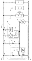
図1は、本発明の実施形態による充放電制御装置1の回路構成の一例を概略的に示している。図1には、本発明の充放電制御装置1が接続される直流給電システム全体を概略的に示している。図示の例では、直流給電システムが、直流母線、バッテリB、系統連係装置40、自然エネルギー発電装置50、負荷装置60を備えている。
(1) Circuit Configuration FIG. 1 schematically shows an example of the circuit configuration of the charge / discharge control device 1 according to the embodiment of the present invention. FIG. 1 schematically shows the entire DC power supply system to which the charge / discharge control device 1 of the present invention is connected. In the illustrated example, the DC power supply system includes a DC bus, a battery B, a
直流母線は、高電位ラインLHと低電位ラインLLで表している。低電位ラインLLの電位を基準電位(零電位)としたときの高電位ラインLHの電圧(以下、「母線電圧]と称する)をVdcで示す。直流母線の高電位ラインLHと低電位ラインLLの間には、系統連係装置40、自然エネルギー発電機50、負荷装置60がそれぞれ並列接続されている。このような直流給電システムは、負荷装置60が正常に動作可能な範囲で母線電圧Vdcが変動するように構成されている。
The DC bus is represented by a high potential line LH and a low potential line LL. The voltage of the high potential line LH (hereinafter referred to as “bus voltage”) when the potential of the low potential line LL is set as the reference potential (zero potential) is indicated by Vdc. The high potential line LH of the DC bus and the low potential line LL. A
自然エネルギー発電装置50は、例えば風力発電装置、太陽光発電装置等であり、異なる種類の複数の発電装置を含む場合もあるが、ここでは概略的に1つの概念として示している。自然エネルギー発電装置50の出力電圧(「自然エネルギー発電電圧」と称する)をVgで示す。自然エネルギー発電電圧は、発電状況によって変動する。
The renewable energy
さらに各発電装置は、その出力電圧の最大電圧を設定されている。例えば、風力発電装置の最大電圧が300Vに設定されている場合、風力発電装置は、その出力電圧Vgが300V以下でありかつ出力電圧Vgより母線電圧Vdcの方が低いときに母線に出力することができる。また例えば、太陽光発電装置の最大電圧が280Vに設定されている場合、太陽光発電装置は、その出力電圧Vgが280V以下でありかつ出力電圧Vgより母線電圧Vdcの方が低いときに母線に出力することができる。 Further, each power generation device is set to the maximum voltage of its output voltage. For example, when the maximum voltage of the wind turbine generator is set to 300 V, the wind turbine generator outputs to the bus when its output voltage Vg is 300 V or less and the bus voltage Vdc is lower than the output voltage Vg. Can be done. Further, for example, when the maximum voltage of the photovoltaic power generation device is set to 280V, the photovoltaic power generation device becomes a bus when its output voltage Vg is 280V or less and the bus voltage Vdc is lower than the output voltage Vg. Can be output.
系統連係装置40の出力電圧(「系統電圧」と称する)をVsで示す。系統連係装置40は、系統電源の交流電圧を直流電圧に変換して母線に出力する。系統電圧Vsは、実質的に変動しない一定の値である。系統連係装置40は、系統電圧Vsより母線電圧Vdcの方が低いときに母線に出力することができる。
The output voltage (referred to as "system voltage") of the
バッテリBは、充放電制御装置1を介在させているが、系統連係装置40、自然エネルギー発電装置50、負荷装置60に対して実質的に並列接続されている。バッテリBは正極pと負極nの端子を有し、負極nは低電位ラインLLに接続されている。負極nを基準電位とする正極pの電圧をバッテリ電圧Vbと称する。バッテリ電圧Vbは、バッテリBの充放電により変動する。
Although the battery B has the charge / discharge control device 1 interposed therebetween, it is substantially connected in parallel to the
充放電制御装置1は、好適例として、直流母線の高電位ラインHLとバッテリBの正極pとの間に配置される。バッテリBの放電時には、正極pから充放電制御装置1を介して高電位ラインHLへ放電電流が流れ、バッテリBの充電時には、高電位ラインHから充放電制御装置1を介してバッテリBの正極pへ充電電流が流れる。 As a preferred example, the charge / discharge control device 1 is arranged between the high potential line HL of the DC bus and the positive electrode p of the battery B. When the battery B is discharged, a discharge current flows from the positive electrode p to the high potential line HL via the charge / discharge control device 1, and when the battery B is charged, the positive electrode of the battery B is charged from the high potential line H via the charge / discharge control device 1. Charging current flows to p.
充放電制御装置1は、主な機能構成部として、充電部10と、通常放電部20と、昇圧放電部30とを有する。これらの機能構成部10、20、30は、いずれもバッテリBの正極pに接続された共通端子を有する。
The charge / discharge control device 1 has a charging
充電部10はさらに、直流母線の高電位ラインHLに接続される2つの外部端子11、12と、検知部13と、スイッチ部14と、充電回路15とを有する。外部端子11は検知部13の入力端子であり、外部端子12は、スイッチ部14の入力端子である。
The charging
検知部13は、母線電圧Vdcを検知する。さらに検知部13は、検知した母線電圧Vdcを基準電圧と比較し、基準電圧を超えているか否かを判定する。基準電圧は、バッテリBの満充電電圧と同じかまたはそれよりも高く設定された所定の電圧(以下、「充電開始電圧」と称する)である。さらに検知部13は、母線電圧Vdcが充電開始電圧を超えているときは、スイッチ部14に電流路を導通させるように指示する制御信号を送る。一方、母線電圧Vdcが充電開始電圧以下であるときは、スイッチ部14に対し電流路を遮断するように指示する制御信号を送る。検知部13は、例えばコンパレータIC等を用いて実施することができる。
The
スイッチ部14は、検知部13からの指示に従って、直流母線と充電回路15との間を導通または遮断する。スイッチ部14が導通しているとき、母線電圧Vdcによる充電電流が充電回路15を通って流れ、バッテリBを充電する。充電回路15は、ここでは一例として、バッテリBへの突入電流を防止し定電流として流すためのリアクトルにより構成されている。このように本発明では、充電回路15を極めて簡素な構成とすることができる。スイッチ部14が遮断されているとき、バッテリBの充電は行われない。スイッチ部14のスイッチ素子は、半導体スイッチング素子または機械的スイッチにより実施できる。検知部13およびスイッチ部14は、DSP(Digital Signal Processor)を用いても実施できる。
The
通常放電部20は、バッテリBがそのバッテリ電圧Vbにより直流母線に直接放電可能であるときに機能する。通常放電部20の稼動条件については、後述する図2で詳細に説明する。
The
通常放電部20は、直流母線の高電位ラインHLに接続された外部端子21と、ダイオード22とを有する。ダイオード22は、アノードがバッテリBの正極pに、カソードが外部端子21すなわち直流母線に接続されている。ダイオード22は、バッテリBから直流母線への放電電流を導通させかつ反対方向の電流を阻止することができる。ダイオード22は整流要素の一例であり、同様の機能を有する整流回路および整流素子に替えることができる。
The
昇圧放電部30は、直流母線の高電位ラインHLに接続された外部端子31と、昇圧回路と、ダイオード35とを有する。
The step-up /
昇圧放電部30の昇圧回路は、バッテリ電圧Vbを、バッテリの満充電電圧より低くかつ系統連係装置40の系統電圧Vsより高い所定の電圧(以下「昇圧放電電圧」と称する)に昇圧する機能を有する。昇圧回路は、バッテリ電圧Vbが昇圧放電電圧より低い場合には、そのバッテリ電圧Vbを昇圧放電電圧まで高める。また、バッテリ電圧Vbが昇圧放電電圧よりも高い場合であっても、昇圧回路の駆動を停止させる必要はない。その場合は、単に昇圧回路から電流が出力されないだけである。昇圧放電部30の稼動条件についても、後述する図2で詳細に説明する。
The booster circuit of the
昇圧回路は、ここでは一例として、リアクトル32と、スイッチング素子33と、PWM(Pulse Width Modulation)信号発生器34とにより構成される非絶縁型スイッチング電源の一種である昇圧チョッパ回路である。図示しない制御回路によって、現時点のバッテリ電圧Vbを検知し、検知されたバッテリ電圧Vbに応じてPWM信号のデューティ比を調整することによりバッテリ電圧Vbを一定の昇圧放電電圧に昇圧させる。このような制御回路は周知である。
The booster circuit is, for example, a booster chopper circuit which is a kind of non-isolated switching power supply composed of a
PWM信号によりスイッチング素子33がオンに制御されるとき、バッテリ電圧Vbによりリアクトル32およびスイッチング素子33に電流が流れてリアクトル32のコアに磁気エネルギーが蓄積される。そしてPWM信号によりスイッチング素子33がオフに制御されるとき、リアクトル32に生じた逆起電力により昇圧放電電圧に到達し、ダイオード35を通して直流母線に放電電流が流れることができる。
When the switching
ダイオード35は、アノードがリアクトル32とスイッチング素子33との接続点に、カソードが外部端子31すなわち直流母線に接続されている。ダイオード35は、バッテリBから直流母線への放電電流を導通させかつ反対方向の電流を阻止することができる。ダイオード35は整流要素の一例であり、同様の機能を有する整流回路および整流素子に替えることができる。
In the
(2)回路動作
図2のグラフおよび図3〜図5を参照して、図1に示した充放電制御装置1の動作を説明する。充放電制御装置1は、変動する稼動条件によって決まる複数の動作モードを有する。稼動条件のパラメータには、少なくとも、現時点の母線電圧Vdc、現時点のバッテリ電圧Vb、母線電圧Vdcと充電開始電圧との関係、および、バッテリ電圧Vbと昇圧放電電圧との関係が含まれる。それらのパラメータによって充放電制御装置1の動作モードが決まる。
(2) Circuit Operation The operation of the charge / discharge control device 1 shown in FIG. 1 will be described with reference to the graph of FIG. 2 and FIGS. 3 to 5. The charge / discharge control device 1 has a plurality of operation modes determined by fluctuating operating conditions. The parameters of the operating conditions include, at least, the current bus voltage Vdc, the current battery voltage Vb, the relationship between the bus voltage Vdc and the charging start voltage, and the relationship between the battery voltage Vb and the boost discharge voltage. The operation mode of the charge / discharge control device 1 is determined by these parameters.
図2のグラフは、充放電制御装置1の稼動条件と動作モードを模式的に表したものである。横軸がバッテリ電圧Vbを、縦軸が母線電圧Vdcを示している。横軸と縦軸の縮尺は同じである。よって、図2のグラフにおいて、点線のラインL1より下の領域ではバッテリ電圧Vbが母線電圧Vdcより高く(Vb>Vdc)、ラインL1より上の領域では母線電圧Vdcがバッテリ電圧Vbより高い(Vdc>Vb)。以下では、図1中の符号も参照して充放電制御装置1の動作を説明する。 The graph of FIG. 2 schematically shows the operating conditions and operating modes of the charge / discharge control device 1. The horizontal axis represents the battery voltage Vb, and the vertical axis represents the bus voltage Vdc. The scales on the horizontal axis and the vertical axis are the same. Therefore, in the graph of FIG. 2, the battery voltage Vb is higher than the bus voltage Vdc in the region below the dotted line L1 (Vb> Vdc), and the bus voltage Vdc is higher than the battery voltage Vb in the region above the line L1 (Vdc). > Vb). Hereinafter, the operation of the charge / discharge control device 1 will be described with reference to the reference numerals in FIG.
バッテリ電圧Vbの変動範囲は、通常、最大電圧である満充電電圧Vb1から最小電圧である放電終止電圧Vb3までの範囲である。ここでは一例として、満充電電圧Vb1を276V、放電終止電圧Vb3を192Vとしている。これは、12V鉛蓄電池(定格2Vのセルを6個接続)を20個接続して構成したバッテリについての一例である。 The fluctuation range of the battery voltage Vb is usually in the range from the maximum charge voltage Vb1 to the minimum discharge end voltage Vb3. Here, as an example, the full charge voltage Vb1 is set to 276V, and the discharge end voltage Vb3 is set to 192V. This is an example of a battery configured by connecting 20 12V lead-acid batteries (six cells with a rating of 2V connected).
図1の昇圧放電部30における昇圧放電電圧Vb2は、満充電電圧Vb1より低くかつ系統連係装置40の系統電圧Vsより高く設定されている。なお、本発明の動作を実現する上で、昇圧放電電圧Vb2は、系統電圧Vsより若干高めに設定すれば十分である。ここでは一例として、系統電圧Vsが269Vであり、それに対して昇圧放電電圧Vb2を270Vに設定している。
The boost discharge voltage Vb2 in the
母線電圧Vdcの変動範囲の最大電圧は、自然エネルギー発電電圧に対して設定された最大電圧Vg1となる。ここでは一例として、最大電圧Vg1を300Vとしている。母線電圧Vdcの変動範囲の最小電圧は、ここでは一例として、系統電圧Vsより若干低い電圧としている。 The maximum voltage in the fluctuation range of the bus voltage Vdc is the maximum voltage Vg1 set with respect to the renewable energy power generation voltage. Here, as an example, the maximum voltage Vg1 is set to 300V. The minimum voltage in the fluctuation range of the bus voltage Vdc is set to a voltage slightly lower than the system voltage Vs as an example here.
図1の充電部10により検知される母線電圧Vdcの充電開始電圧Vg2は、バッテリBの満充電電圧Vb1と同じかまたはそれよりも高く設定されている。充電開始電圧Vg2を満充電電圧Vb1より高く設定する場合、若干高めであれば十分である。ここでは一例として、満充電電圧Vb1が276Vのとき、充電開始電圧Vg2を277Vに設定している。
The charging start voltage Vg2 of the bus voltage Vdc detected by the charging
以上のような稼動条件の下で充放電制御装置1は、図2に示したAモード、Bモード、およびCモードの3つの主要な動作モードを有する。 Under the above operating conditions, the charge / discharge control device 1 has three main operation modes, A mode, B mode, and C mode shown in FIG.
<Aモード:充電領域>
図2において、充電領域AはAモード動作が行われる領域であり、この領域では母線電圧VdcによりバッテリBが充電される充電動作が行われる。そしてバッテリBの充電はAモードにおいてのみ行われる。Aモードの稼動条件は、母線電圧Vdcが充電開始電圧Vg2以上であることである。Aモードの動作は、充放電制御装置1の充電部10により行われ、バッテリ電圧Vbがどのような値であっても優先的に実行される。
<A mode: Charging area>
In FIG. 2, the charging region A is a region where the A mode operation is performed, and in this region, the charging operation in which the battery B is charged by the bus voltage Vdc is performed. And the battery B is charged only in the A mode. The operating condition of the A mode is that the bus voltage Vdc is equal to or higher than the charging start voltage Vg2. The operation of the A mode is performed by the charging
充電開始電圧Vg2は、バッテリBの最大電圧である満充電電圧Vb1以上であるので、AモードにおいてバッテリBは必ず充電される。また、充電開始電圧Vg2は当然に系統電圧Vsよりも高いので、AモードにおいてバッテリBが系統電圧Vsにより充電されることは起こり得ず、バッテリBは必ず自然エネルギー発電電圧Vgのみにより充電されることとなる。 Since the charging start voltage Vg2 is equal to or higher than the full charge voltage Vb1 which is the maximum voltage of the battery B, the battery B is always charged in the A mode. Further, since the charging start voltage Vg2 is naturally higher than the system voltage Vs, the battery B cannot be charged by the system voltage Vs in the A mode, and the battery B is always charged only by the natural energy power generation voltage Vg. It will be.
図3は、図1の回路におけるAモードの電流の流れを概略的示している。この場合、充電電流は、自然エネルギー発電装置50から直流母線へと出力され、充放電制御装置1の充電部10の外部端子12からスイッチ部14および充電回路15を通ってバッテリBに流れる。
FIG. 3 schematically shows the flow of A-mode current in the circuit of FIG. In this case, the charging current is output from the renewable energy
<Bモード:通常放電領域>
図2において、通常放電領域BはBモード動作が行われる領域であり、この領域では、図1の充放電制御装置1の通常放電部20により放電が行われる。Bモードの稼動条件は、バッテリ電圧Vbが、昇圧放電電圧Vb2と満充電電圧Vb1との間にあることである。但し、母線電圧Vdcは、バッテリ電圧Vbより低くなければならない(図2のラインL1より下の領域)。
<B mode: Normal discharge area>
In FIG. 2, the normal discharge region B is a region where the B mode operation is performed, and in this region, discharge is performed by the
なお、充放電制御装置1の昇圧放電部30は、昇圧放電電圧Vb2以上の電圧を出力できないので、Bモードでは放電電流を出力することができない。よって、バッテリ電圧Vbが昇圧放電電圧Vb2と満充電電圧Vb1との間にあるとき、通常放電部20は、昇圧放電部30に対して優先的に放電電流を流す。
Since the
図4は、図1の回路におけるBモードの電流の流れを概略的示している。この場合、放電電流は、バッテリBから充放電制御装置1の通常放電部20を通って直流母線へ出力され、そして負荷装置60へと流れる。
FIG. 4 schematically shows the flow of the B-mode current in the circuit of FIG. In this case, the discharge current is output from the battery B to the DC bus through the
<Cモード:昇圧放電領域>
図2において、昇圧放電領域CはCモード動作を行う領域であり、この領域では図1の充放電制御装置1の昇圧放電部30により放電が行われる。Cモードの稼動条件は、バッテリ電圧Vbが昇圧放電電圧Vb2以下であることである。したがって、Cモードでは、昇圧回路によりバッテリ電圧Vbを昇圧放電電圧Vb2まで昇圧し、昇圧放電電圧Vb2により直流母線に放電電流を流す。
<C mode: step-up discharge area>
In FIG. 2, the step-up / discharge region C is a region in which C-mode operation is performed, and in this region, discharge is performed by the boost-
仮にバッテリ電圧Vbの昇圧を行わないとすれば、バッテリ電圧Vbが系統電圧Vsより低い範囲では系統電圧Vsから直流母線への出力が優先的に生じることになる。昇圧放電領域Cの全ての座標点におけるバッテリ電圧Vbは昇圧放電電圧Vb2に昇圧されるので、系統連係装置40よりもバッテリBからの放電が優先されることになる。
If the battery voltage Vb is not boosted, the output from the system voltage Vs to the DC bus will be preferentially generated in the range where the battery voltage Vb is lower than the system voltage Vs. Since the battery voltage Vb at all the coordinate points of the boost-discharge region C is boosted to the boost-discharge voltage Vb2, the discharge from the battery B is prioritized over the
図5は、図1の回路におけるCモードの電流の流れを概略的示している。この場合、放電電流は、バッテリBから充放電制御装置1の昇圧放電部30を通って直流母線へ出力され、そして負荷装置60へと流れる。
FIG. 5 schematically shows the flow of C-mode current in the circuit of FIG. In this case, the discharge current is output from the battery B to the DC bus through the
なお、BモードとCモードの間の移行は、切り替え制御無しでバッテリ電圧Vbに依存して自然に行われる。これによっても、充放電制御装置1の構成が簡素化される。また、CモードでのバッテリBの昇圧放電中にバッテリBの充電が生じる可能性は全くない(充電は充電領域Aでのみ行われるため)ので、自己充電を抑制するための監視および制御も不要である。 The transition between the B mode and the C mode is naturally performed depending on the battery voltage Vb without switching control. This also simplifies the configuration of the charge / discharge control device 1. Further, since there is no possibility that the battery B will be charged during the step-up / discharge of the battery B in the C mode (since the charging is performed only in the charging area A), monitoring and control for suppressing self-charging are unnecessary. Is.
以上に説明した本発明の実施形態の具体的構成は、図示の例に限られず、本発明の主旨に沿う範囲において多様な変形が可能である。 The specific configuration of the embodiment of the present invention described above is not limited to the illustrated example, and various modifications can be made within a range in line with the gist of the present invention.
1 充放電制御装置
10 充電部
11、12 外部端子
13 検知部
14 スイッチ部
15 充電回路
20 通常放電部
21 外部端子
22 ダイオード
30 昇圧放電部
31 外部端子
32 リアクトル
33 スイッチング素子
34 PWM信号生成部
35 ダイオード
40 系統連係装置
50 自然エネルギー発電装置
60 負荷装置
H 高電位ライン
L 低電位ライン
1 Charging / discharging
Claims (6)
前記直流母線の母線電圧が、前記バッテリの満充電電圧と同じかまたはそれよりも高い充電開始電圧を超えているときにのみ、前記直流母線から前記バッテリに充電可能とする充電部と、
前記バッテリのバッテリ電圧を、前記満充電電圧より低くかつ前記系統連係装置の系統電圧より高い昇圧放電電圧まで昇圧して当該昇圧放電電圧により前記バッテリから前記直流母線に放電可能とする昇圧放電部と、
前記バッテリのバッテリ電圧が、前記昇圧放電電圧と前記満充電電圧との間であるとき、当該バッテリ電圧により前記直流母線に放電可能とする通常放電部とを有することを特徴とするバッテリの充放電制御装置。 A battery, a renewable energy power generation device in which a maximum output voltage higher than the full charge voltage of the battery is set, a system linkage device capable of outputting a system voltage lower than the full charge voltage of the battery, and a load device are connected. A charge / discharge control device that is connected between the DC bus and the battery and controls the charge / discharge of the battery.
A charging unit that enables charging of the battery from the DC bus only when the bus voltage of the DC bus exceeds the charging start voltage equal to or higher than the full charge voltage of the battery.
With a boost discharge unit that boosts the battery voltage of the battery to a boost discharge voltage lower than the full charge voltage and higher than the grid voltage of the grid linkage device so that the battery can be discharged from the battery to the DC bus by the boost discharge voltage. ,
When the battery voltage of the battery is between the boost discharge voltage and the full charge voltage, the battery is charged and discharged so as to have a normal discharge unit capable of discharging the DC bus by the battery voltage. Control device.
前記母線電圧が前記充電開始電圧を超えているか否かを検知する検知部と、
前記検知部の検知結果に基づいて、前記母線電圧が前記充電開始電圧を超えているときは前記直流母線と前記バッテリとを接続し、かつ前記充電開始電圧以下のときは前記直流母線と前記バッテリとを遮断するスイッチ部とを具備することを特徴とする請求項1に記載のバッテリの充放電制御装置。 The charging part
A detection unit that detects whether or not the bus voltage exceeds the charging start voltage,
Based on the detection result of the detection unit, when the bus voltage exceeds the charging start voltage, the DC bus and the battery are connected, and when the charging start voltage or less, the DC bus and the battery are connected. The battery charge / discharge control device according to claim 1, further comprising a switch unit that shuts off and.
Priority Applications (1)
| Application Number | Priority Date | Filing Date | Title |
|---|---|---|---|
| JP2019145755A JP7272897B2 (en) | 2019-08-07 | 2019-08-07 | Charge/discharge control device and battery and DC power supply system equipped with the same |
Applications Claiming Priority (1)
| Application Number | Priority Date | Filing Date | Title |
|---|---|---|---|
| JP2019145755A JP7272897B2 (en) | 2019-08-07 | 2019-08-07 | Charge/discharge control device and battery and DC power supply system equipped with the same |
Publications (2)
| Publication Number | Publication Date |
|---|---|
| JP2021027749A true JP2021027749A (en) | 2021-02-22 |
| JP7272897B2 JP7272897B2 (en) | 2023-05-12 |
Family
ID=74664075
Family Applications (1)
| Application Number | Title | Priority Date | Filing Date |
|---|---|---|---|
| JP2019145755A Active JP7272897B2 (en) | 2019-08-07 | 2019-08-07 | Charge/discharge control device and battery and DC power supply system equipped with the same |
Country Status (1)
| Country | Link |
|---|---|
| JP (1) | JP7272897B2 (en) |
Cited By (1)
| Publication number | Priority date | Publication date | Assignee | Title |
|---|---|---|---|---|
| CN113890001A (en) * | 2021-09-29 | 2022-01-04 | 国网湖北省电力有限公司宜昌供电公司 | One-key operation method for electric operation type two-power two-charging direct current system |
Citations (6)
| Publication number | Priority date | Publication date | Assignee | Title |
|---|---|---|---|---|
| JP2003339118A (en) * | 2002-05-22 | 2003-11-28 | My Way Giken Kk | Distributed power supply system |
| JP2014103822A (en) * | 2012-11-22 | 2014-06-05 | Sharp Corp | Current controller for power storage device |
| JP2018019577A (en) * | 2016-07-29 | 2018-02-01 | パナソニックIpマネジメント株式会社 | Power supply system |
| JP2019030104A (en) * | 2017-07-28 | 2019-02-21 | 住友電気工業株式会社 | Power supply system, operation method of the same, and electric power conversion system |
| JP2019058053A (en) * | 2017-07-06 | 2019-04-11 | Ntn株式会社 | Direct current power supply system |
| JP2019071749A (en) * | 2017-10-11 | 2019-05-09 | Ntn株式会社 | Dc power feeding system |
-
2019
- 2019-08-07 JP JP2019145755A patent/JP7272897B2/en active Active
Patent Citations (6)
| Publication number | Priority date | Publication date | Assignee | Title |
|---|---|---|---|---|
| JP2003339118A (en) * | 2002-05-22 | 2003-11-28 | My Way Giken Kk | Distributed power supply system |
| JP2014103822A (en) * | 2012-11-22 | 2014-06-05 | Sharp Corp | Current controller for power storage device |
| JP2018019577A (en) * | 2016-07-29 | 2018-02-01 | パナソニックIpマネジメント株式会社 | Power supply system |
| JP2019058053A (en) * | 2017-07-06 | 2019-04-11 | Ntn株式会社 | Direct current power supply system |
| JP2019030104A (en) * | 2017-07-28 | 2019-02-21 | 住友電気工業株式会社 | Power supply system, operation method of the same, and electric power conversion system |
| JP2019071749A (en) * | 2017-10-11 | 2019-05-09 | Ntn株式会社 | Dc power feeding system |
Cited By (2)
| Publication number | Priority date | Publication date | Assignee | Title |
|---|---|---|---|---|
| CN113890001A (en) * | 2021-09-29 | 2022-01-04 | 国网湖北省电力有限公司宜昌供电公司 | One-key operation method for electric operation type two-power two-charging direct current system |
| CN113890001B (en) * | 2021-09-29 | 2023-11-10 | 国网湖北省电力有限公司宜昌供电公司 | One-key operation method of electric operation type two-electricity two-charging direct current system |
Also Published As
| Publication number | Publication date |
|---|---|
| JP7272897B2 (en) | 2023-05-12 |
Similar Documents
| Publication | Publication Date | Title |
|---|---|---|
| JP6706349B2 (en) | Uninterruptible power supply system and uninterruptible power supply | |
| JP5882845B2 (en) | Power storage type solar power generation system | |
| EP2991183B1 (en) | Charging and discharging system and method, and photovoltaic power generation system | |
| JP2008131736A (en) | Distributed power system and step-up/step-down chopper device | |
| CN108649792B (en) | Boost circuit, switching power supply, power supply system and control method | |
| JP2011250608A (en) | Solar cell system | |
| JP2013042627A (en) | Dc power supply control device and dc power supply control method | |
| JP7228949B2 (en) | power converter | |
| US6853097B2 (en) | Uniterruptible power supply and its starting method | |
| US20230402863A1 (en) | Energy System and Charging and Discharging Control Method | |
| JP2005269843A (en) | Parallel operation device | |
| KR100844401B1 (en) | Uninterrupted power supply apparatus with a solar generating apparatus | |
| JP7272897B2 (en) | Charge/discharge control device and battery and DC power supply system equipped with the same | |
| TWI655827B (en) | Uninterruptible power supply | |
| JP2008035573A (en) | Electricity accumulation device employing electric double layer capacitor | |
| CN112438008A (en) | Uninterruptible power supply device | |
| CN213185554U (en) | Battery management circuit and battery management control system | |
| US11539223B2 (en) | Charging/discharging apparatus | |
| US20220399746A1 (en) | Power converter | |
| JP2568271B2 (en) | DC uninterruptible power supply | |
| JP5810254B2 (en) | Power storage device | |
| JP2017158265A (en) | Electric power supply system and electric power conversion system | |
| JP2011211812A (en) | Power unit | |
| JP2011186583A (en) | Circuit device and electronic equipment | |
| JPWO2018155442A1 (en) | DC power supply system |
Legal Events
| Date | Code | Title | Description |
|---|---|---|---|
| A621 | Written request for application examination |
Free format text: JAPANESE INTERMEDIATE CODE: A621 Effective date: 20220726 |
|
| A977 | Report on retrieval |
Free format text: JAPANESE INTERMEDIATE CODE: A971007 Effective date: 20230316 |
|
| TRDD | Decision of grant or rejection written | ||
| A01 | Written decision to grant a patent or to grant a registration (utility model) |
Free format text: JAPANESE INTERMEDIATE CODE: A01 Effective date: 20230404 |
|
| A61 | First payment of annual fees (during grant procedure) |
Free format text: JAPANESE INTERMEDIATE CODE: A61 Effective date: 20230427 |
|
| R150 | Certificate of patent or registration of utility model |
Ref document number: 7272897 Country of ref document: JP Free format text: JAPANESE INTERMEDIATE CODE: R150 |