RU2417110C2 - Low pressure feed system having manually activated pump for mild wound healing - Google Patents
Low pressure feed system having manually activated pump for mild wound healing Download PDFInfo
- Publication number
- RU2417110C2 RU2417110C2 RU2009111101/14A RU2009111101A RU2417110C2 RU 2417110 C2 RU2417110 C2 RU 2417110C2 RU 2009111101/14 A RU2009111101/14 A RU 2009111101/14A RU 2009111101 A RU2009111101 A RU 2009111101A RU 2417110 C2 RU2417110 C2 RU 2417110C2
- Authority
- RU
- Russia
- Prior art keywords
- inner chamber
- casing
- end cap
- side wall
- reduced pressure
- Prior art date
Links
- 230000029663 wound healing Effects 0.000 title description 2
- 238000000034 method Methods 0.000 claims abstract description 9
- 230000001225 therapeutic effect Effects 0.000 claims abstract 3
- 239000012530 fluid Substances 0.000 claims description 27
- 238000004891 communication Methods 0.000 claims description 20
- 230000002209 hydrophobic effect Effects 0.000 claims description 6
- 239000007788 liquid Substances 0.000 claims description 6
- 235000019645 odor Nutrition 0.000 claims description 6
- 239000006260 foam Substances 0.000 claims description 4
- 239000007789 gas Substances 0.000 claims description 4
- 238000007906 compression Methods 0.000 claims description 3
- 230000006378 damage Effects 0.000 claims description 3
- 208000001953 Hypotension Diseases 0.000 claims description 2
- 230000002745 absorbent Effects 0.000 claims description 2
- 239000002250 absorbent Substances 0.000 claims description 2
- 230000003213 activating effect Effects 0.000 claims description 2
- 208000012866 low blood pressure Diseases 0.000 claims description 2
- 230000000007 visual effect Effects 0.000 claims description 2
- 230000015572 biosynthetic process Effects 0.000 claims 2
- 239000000126 substance Substances 0.000 abstract description 2
- 210000000078 claw Anatomy 0.000 abstract 3
- 239000003814 drug Substances 0.000 abstract 2
- 230000004913 activation Effects 0.000 abstract 1
- 230000000694 effects Effects 0.000 abstract 1
- 230000007420 reactivation Effects 0.000 abstract 1
- 210000001519 tissue Anatomy 0.000 description 27
- 206010052428 Wound Diseases 0.000 description 17
- 208000027418 Wounds and injury Diseases 0.000 description 17
- 239000000017 hydrogel Substances 0.000 description 8
- 239000000463 material Substances 0.000 description 6
- 230000008901 benefit Effects 0.000 description 4
- 238000002560 therapeutic procedure Methods 0.000 description 4
- 230000007423 decrease Effects 0.000 description 3
- 210000000416 exudates and transudate Anatomy 0.000 description 3
- OKTJSMMVPCPJKN-UHFFFAOYSA-N Carbon Chemical compound [C] OKTJSMMVPCPJKN-UHFFFAOYSA-N 0.000 description 2
- 230000006835 compression Effects 0.000 description 2
- 230000005611 electricity Effects 0.000 description 2
- 238000004519 manufacturing process Methods 0.000 description 2
- 238000012986 modification Methods 0.000 description 2
- 230000004048 modification Effects 0.000 description 2
- 238000012360 testing method Methods 0.000 description 2
- 239000000853 adhesive Substances 0.000 description 1
- 230000001070 adhesive effect Effects 0.000 description 1
- 239000002313 adhesive film Substances 0.000 description 1
- 230000009286 beneficial effect Effects 0.000 description 1
- 230000017531 blood circulation Effects 0.000 description 1
- 239000011248 coating agent Substances 0.000 description 1
- 238000000576 coating method Methods 0.000 description 1
- 238000013461 design Methods 0.000 description 1
- 238000011161 development Methods 0.000 description 1
- 238000009826 distribution Methods 0.000 description 1
- 238000005516 engineering process Methods 0.000 description 1
- 210000000981 epithelium Anatomy 0.000 description 1
- 238000001125 extrusion Methods 0.000 description 1
- 239000004744 fabric Substances 0.000 description 1
- 238000013508 migration Methods 0.000 description 1
- 230000005012 migration Effects 0.000 description 1
- 210000004115 mitral valve Anatomy 0.000 description 1
- 238000009581 negative-pressure wound therapy Methods 0.000 description 1
- 206010033675 panniculitis Diseases 0.000 description 1
- 229920002635 polyurethane Polymers 0.000 description 1
- 239000004814 polyurethane Substances 0.000 description 1
- 238000003825 pressing Methods 0.000 description 1
- 230000009467 reduction Effects 0.000 description 1
- 239000000565 sealant Substances 0.000 description 1
- 238000007789 sealing Methods 0.000 description 1
- 210000004304 subcutaneous tissue Anatomy 0.000 description 1
Images


Classifications
-
- A—HUMAN NECESSITIES
- A61—MEDICAL OR VETERINARY SCIENCE; HYGIENE
- A61M—DEVICES FOR INTRODUCING MEDIA INTO, OR ONTO, THE BODY; DEVICES FOR TRANSDUCING BODY MEDIA OR FOR TAKING MEDIA FROM THE BODY; DEVICES FOR PRODUCING OR ENDING SLEEP OR STUPOR
- A61M27/00—Drainage appliance for wounds or the like, i.e. wound drains, implanted drains
-
- A—HUMAN NECESSITIES
- A61—MEDICAL OR VETERINARY SCIENCE; HYGIENE
- A61M—DEVICES FOR INTRODUCING MEDIA INTO, OR ONTO, THE BODY; DEVICES FOR TRANSDUCING BODY MEDIA OR FOR TAKING MEDIA FROM THE BODY; DEVICES FOR PRODUCING OR ENDING SLEEP OR STUPOR
- A61M1/00—Suction or pumping devices for medical purposes; Devices for carrying-off, for treatment of, or for carrying-over, body-liquids; Drainage systems
-
- A—HUMAN NECESSITIES
- A61—MEDICAL OR VETERINARY SCIENCE; HYGIENE
- A61F—FILTERS IMPLANTABLE INTO BLOOD VESSELS; PROSTHESES; DEVICES PROVIDING PATENCY TO, OR PREVENTING COLLAPSING OF, TUBULAR STRUCTURES OF THE BODY, e.g. STENTS; ORTHOPAEDIC, NURSING OR CONTRACEPTIVE DEVICES; FOMENTATION; TREATMENT OR PROTECTION OF EYES OR EARS; BANDAGES, DRESSINGS OR ABSORBENT PADS; FIRST-AID KITS
- A61F13/00—Bandages or dressings; Absorbent pads
- A61F13/02—Adhesive plasters or dressings
- A61F13/0203—Adhesive plasters or dressings having a fluid handling member
- A61F13/0206—Adhesive plasters or dressings having a fluid handling member the fluid handling member being absorbent fibrous layer, e.g. woven or nonwoven absorbent pad, island dressings
-
- A—HUMAN NECESSITIES
- A61—MEDICAL OR VETERINARY SCIENCE; HYGIENE
- A61F—FILTERS IMPLANTABLE INTO BLOOD VESSELS; PROSTHESES; DEVICES PROVIDING PATENCY TO, OR PREVENTING COLLAPSING OF, TUBULAR STRUCTURES OF THE BODY, e.g. STENTS; ORTHOPAEDIC, NURSING OR CONTRACEPTIVE DEVICES; FOMENTATION; TREATMENT OR PROTECTION OF EYES OR EARS; BANDAGES, DRESSINGS OR ABSORBENT PADS; FIRST-AID KITS
- A61F13/00—Bandages or dressings; Absorbent pads
- A61F13/02—Adhesive plasters or dressings
- A61F13/0246—Adhesive plasters or dressings characterised by the skin adhering layer
- A61F13/0253—Adhesive plasters or dressings characterised by the skin adhering layer characterized by the adhesive material
-
- A—HUMAN NECESSITIES
- A61—MEDICAL OR VETERINARY SCIENCE; HYGIENE
- A61F—FILTERS IMPLANTABLE INTO BLOOD VESSELS; PROSTHESES; DEVICES PROVIDING PATENCY TO, OR PREVENTING COLLAPSING OF, TUBULAR STRUCTURES OF THE BODY, e.g. STENTS; ORTHOPAEDIC, NURSING OR CONTRACEPTIVE DEVICES; FOMENTATION; TREATMENT OR PROTECTION OF EYES OR EARS; BANDAGES, DRESSINGS OR ABSORBENT PADS; FIRST-AID KITS
- A61F13/00—Bandages or dressings; Absorbent pads
- A61F13/02—Adhesive plasters or dressings
- A61F13/0259—Adhesive plasters or dressings characterised by the release liner covering the skin adhering layer
- A61F13/0263—Adhesive plasters or dressings characterised by the release liner covering the skin adhering layer especially adapted for island dressings
-
- A61F13/05—
-
- A—HUMAN NECESSITIES
- A61—MEDICAL OR VETERINARY SCIENCE; HYGIENE
- A61M—DEVICES FOR INTRODUCING MEDIA INTO, OR ONTO, THE BODY; DEVICES FOR TRANSDUCING BODY MEDIA OR FOR TAKING MEDIA FROM THE BODY; DEVICES FOR PRODUCING OR ENDING SLEEP OR STUPOR
- A61M1/00—Suction or pumping devices for medical purposes; Devices for carrying-off, for treatment of, or for carrying-over, body-liquids; Drainage systems
- A61M1/64—Containers with integrated suction means
- A61M1/68—Containers incorporating a flexible member creating suction
- A61M1/684—Containers incorporating a flexible member creating suction bellows-type
-
- A—HUMAN NECESSITIES
- A61—MEDICAL OR VETERINARY SCIENCE; HYGIENE
- A61M—DEVICES FOR INTRODUCING MEDIA INTO, OR ONTO, THE BODY; DEVICES FOR TRANSDUCING BODY MEDIA OR FOR TAKING MEDIA FROM THE BODY; DEVICES FOR PRODUCING OR ENDING SLEEP OR STUPOR
- A61M1/00—Suction or pumping devices for medical purposes; Devices for carrying-off, for treatment of, or for carrying-over, body-liquids; Drainage systems
- A61M1/71—Suction drainage systems
- A61M1/73—Suction drainage systems comprising sensors or indicators for physical values
-
- A—HUMAN NECESSITIES
- A61—MEDICAL OR VETERINARY SCIENCE; HYGIENE
- A61M—DEVICES FOR INTRODUCING MEDIA INTO, OR ONTO, THE BODY; DEVICES FOR TRANSDUCING BODY MEDIA OR FOR TAKING MEDIA FROM THE BODY; DEVICES FOR PRODUCING OR ENDING SLEEP OR STUPOR
- A61M1/00—Suction or pumping devices for medical purposes; Devices for carrying-off, for treatment of, or for carrying-over, body-liquids; Drainage systems
- A61M1/71—Suction drainage systems
- A61M1/74—Suction control
- A61M1/743—Suction control by changing the cross-section of the line, e.g. flow regulating valves
-
- A—HUMAN NECESSITIES
- A61—MEDICAL OR VETERINARY SCIENCE; HYGIENE
- A61M—DEVICES FOR INTRODUCING MEDIA INTO, OR ONTO, THE BODY; DEVICES FOR TRANSDUCING BODY MEDIA OR FOR TAKING MEDIA FROM THE BODY; DEVICES FOR PRODUCING OR ENDING SLEEP OR STUPOR
- A61M1/00—Suction or pumping devices for medical purposes; Devices for carrying-off, for treatment of, or for carrying-over, body-liquids; Drainage systems
- A61M1/71—Suction drainage systems
- A61M1/78—Means for preventing overflow or contamination of the pumping systems
-
- A—HUMAN NECESSITIES
- A61—MEDICAL OR VETERINARY SCIENCE; HYGIENE
- A61M—DEVICES FOR INTRODUCING MEDIA INTO, OR ONTO, THE BODY; DEVICES FOR TRANSDUCING BODY MEDIA OR FOR TAKING MEDIA FROM THE BODY; DEVICES FOR PRODUCING OR ENDING SLEEP OR STUPOR
- A61M1/00—Suction or pumping devices for medical purposes; Devices for carrying-off, for treatment of, or for carrying-over, body-liquids; Drainage systems
- A61M1/80—Suction pumps
- A61M1/802—Suction pumps by vacuum created above a liquid flowing from a closed container
-
- A—HUMAN NECESSITIES
- A61—MEDICAL OR VETERINARY SCIENCE; HYGIENE
- A61M—DEVICES FOR INTRODUCING MEDIA INTO, OR ONTO, THE BODY; DEVICES FOR TRANSDUCING BODY MEDIA OR FOR TAKING MEDIA FROM THE BODY; DEVICES FOR PRODUCING OR ENDING SLEEP OR STUPOR
- A61M1/00—Suction or pumping devices for medical purposes; Devices for carrying-off, for treatment of, or for carrying-over, body-liquids; Drainage systems
- A61M1/80—Suction pumps
- A61M1/82—Membrane pumps, e.g. bulbs
-
- A—HUMAN NECESSITIES
- A61—MEDICAL OR VETERINARY SCIENCE; HYGIENE
- A61M—DEVICES FOR INTRODUCING MEDIA INTO, OR ONTO, THE BODY; DEVICES FOR TRANSDUCING BODY MEDIA OR FOR TAKING MEDIA FROM THE BODY; DEVICES FOR PRODUCING OR ENDING SLEEP OR STUPOR
- A61M1/00—Suction or pumping devices for medical purposes; Devices for carrying-off, for treatment of, or for carrying-over, body-liquids; Drainage systems
- A61M1/84—Drainage tubes; Aspiration tips
-
- A—HUMAN NECESSITIES
- A61—MEDICAL OR VETERINARY SCIENCE; HYGIENE
- A61M—DEVICES FOR INTRODUCING MEDIA INTO, OR ONTO, THE BODY; DEVICES FOR TRANSDUCING BODY MEDIA OR FOR TAKING MEDIA FROM THE BODY; DEVICES FOR PRODUCING OR ENDING SLEEP OR STUPOR
- A61M1/00—Suction or pumping devices for medical purposes; Devices for carrying-off, for treatment of, or for carrying-over, body-liquids; Drainage systems
- A61M1/90—Negative pressure wound therapy devices, i.e. devices for applying suction to a wound to promote healing, e.g. including a vacuum dressing
- A61M1/96—Suction control thereof
- A61M1/962—Suction control thereof having pumping means on the suction site, e.g. miniature pump on dressing or dressing capable of exerting suction
-
- A—HUMAN NECESSITIES
- A61—MEDICAL OR VETERINARY SCIENCE; HYGIENE
- A61M—DEVICES FOR INTRODUCING MEDIA INTO, OR ONTO, THE BODY; DEVICES FOR TRANSDUCING BODY MEDIA OR FOR TAKING MEDIA FROM THE BODY; DEVICES FOR PRODUCING OR ENDING SLEEP OR STUPOR
- A61M1/00—Suction or pumping devices for medical purposes; Devices for carrying-off, for treatment of, or for carrying-over, body-liquids; Drainage systems
- A61M1/90—Negative pressure wound therapy devices, i.e. devices for applying suction to a wound to promote healing, e.g. including a vacuum dressing
- A61M1/98—Containers specifically adapted for negative pressure wound therapy
-
- A—HUMAN NECESSITIES
- A61—MEDICAL OR VETERINARY SCIENCE; HYGIENE
- A61M—DEVICES FOR INTRODUCING MEDIA INTO, OR ONTO, THE BODY; DEVICES FOR TRANSDUCING BODY MEDIA OR FOR TAKING MEDIA FROM THE BODY; DEVICES FOR PRODUCING OR ENDING SLEEP OR STUPOR
- A61M39/00—Tubes, tube connectors, tube couplings, valves, access sites or the like, specially adapted for medical use
- A61M39/22—Valves or arrangement of valves
- A61M39/24—Check- or non-return valves
-
- A—HUMAN NECESSITIES
- A61—MEDICAL OR VETERINARY SCIENCE; HYGIENE
- A61M—DEVICES FOR INTRODUCING MEDIA INTO, OR ONTO, THE BODY; DEVICES FOR TRANSDUCING BODY MEDIA OR FOR TAKING MEDIA FROM THE BODY; DEVICES FOR PRODUCING OR ENDING SLEEP OR STUPOR
- A61M1/00—Suction or pumping devices for medical purposes; Devices for carrying-off, for treatment of, or for carrying-over, body-liquids; Drainage systems
- A61M1/71—Suction drainage systems
- A61M1/73—Suction drainage systems comprising sensors or indicators for physical values
- A61M1/732—Visual indicating means for vacuum pressure
-
- A—HUMAN NECESSITIES
- A61—MEDICAL OR VETERINARY SCIENCE; HYGIENE
- A61M—DEVICES FOR INTRODUCING MEDIA INTO, OR ONTO, THE BODY; DEVICES FOR TRANSDUCING BODY MEDIA OR FOR TAKING MEDIA FROM THE BODY; DEVICES FOR PRODUCING OR ENDING SLEEP OR STUPOR
- A61M1/00—Suction or pumping devices for medical purposes; Devices for carrying-off, for treatment of, or for carrying-over, body-liquids; Drainage systems
- A61M1/90—Negative pressure wound therapy devices, i.e. devices for applying suction to a wound to promote healing, e.g. including a vacuum dressing
- A61M1/91—Suction aspects of the dressing
- A61M1/912—Connectors between dressing and drainage tube
-
- A—HUMAN NECESSITIES
- A61—MEDICAL OR VETERINARY SCIENCE; HYGIENE
- A61M—DEVICES FOR INTRODUCING MEDIA INTO, OR ONTO, THE BODY; DEVICES FOR TRANSDUCING BODY MEDIA OR FOR TAKING MEDIA FROM THE BODY; DEVICES FOR PRODUCING OR ENDING SLEEP OR STUPOR
- A61M2205/00—General characteristics of the apparatus
- A61M2205/58—Means for facilitating use, e.g. by people with impaired vision
- A61M2205/581—Means for facilitating use, e.g. by people with impaired vision by audible feedback
-
- A—HUMAN NECESSITIES
- A61—MEDICAL OR VETERINARY SCIENCE; HYGIENE
- A61M—DEVICES FOR INTRODUCING MEDIA INTO, OR ONTO, THE BODY; DEVICES FOR TRANSDUCING BODY MEDIA OR FOR TAKING MEDIA FROM THE BODY; DEVICES FOR PRODUCING OR ENDING SLEEP OR STUPOR
- A61M2205/00—General characteristics of the apparatus
- A61M2205/75—General characteristics of the apparatus with filters
- A61M2205/7536—General characteristics of the apparatus with filters allowing gas passage, but preventing liquid passage, e.g. liquophobic, hydrophobic, water-repellent membranes
Abstract
Description
ПРЕДПОСЫЛКИ ИЗОБРЕТЕНИЯBACKGROUND OF THE INVENTION
1. ОБЛАСТЬ ИЗОБРЕТЕНИЯ1. FIELD OF THE INVENTION
Настоящее изобретение относится в целом к системам лечения пониженным давлением и, в частности, к системам лечения пониженным давлением, имеющим вручную активируемый насос, для обеспечения лечения ран низкой степени тяжести.The present invention relates generally to low pressure treatment systems and, in particular, to low pressure treatment systems having a manually activated pump to provide treatment of low severity wounds.
2. ОПИСАНИЕ УРОВНЯ ТЕХНИКИ2. Description of the level of technology
Клинические исследования и практика показали, что приложение пониженного давления вблизи участка ткани увеличивает и ускоряет рост новой ткани на этом участке ткани. Применения этого явления многочисленны, но приложение пониженного давления было особенно успешным в лечении ран. Это лечение (часто упоминаемое в медицинском сообществе как «терапия раны отрицательным давлением», «терапия пониженным давлением» или «вакуумная терапия») обеспечивает много преимуществ, включая увеличенную миграцию эпителиальных и подкожных тканей, улучшенного кровотока и микродеформации ткани на участке раны. Вместе эти преимущества приводят к ускоренному развитию гранулированной ткани и к уменьшению времени заживления раны.Clinical studies and practice have shown that the application of reduced pressure near a tissue site increases and accelerates the growth of new tissue in this tissue site. The applications of this phenomenon are numerous, but the application of reduced pressure has been particularly successful in the treatment of wounds. This treatment (often referred to in the medical community as “negative pressure wound therapy”, “low pressure therapy” or “vacuum therapy”) provides many benefits, including increased migration of epithelial and subcutaneous tissues, improved blood flow and tissue microdeformation in the wound site. Together, these advantages lead to the accelerated development of granular tissue and to a reduction in wound healing time.
Хотя лечение пониженным давлением обычно осуществляется в больнице или в месте, оборудованном для мониторинга за терапией, существует большое количество ситуаций, в которых может быть выгодно осуществлять терапию пониженным давлением амбулаторным и другим пациентам за пределами этих традиционных мест. Традиционная система пониженного давления содержит электрически приводимый в действие насос пониженного давления, в результате чего для пациента необходимо оставаться относительно неподвижным во время лечения. Таким образом, существует необходимость в портативном насосе небольшого размера, выполненным с возможностью активации вручную и с возможностью повторного приведения в действие в случае необходимости самим пациентом, получающим лечение.Although low pressure treatment is usually carried out in a hospital or in a place equipped to monitor therapy, there are a large number of situations in which it may be beneficial to administer low pressure therapy to outpatients and other patients outside these traditional places. The conventional reduced pressure system comprises an electrically driven reduced pressure pump, whereby it is necessary for the patient to remain relatively stationary during treatment. Thus, there is a need for a small portable pump configured to be manually activated and, if necessary, re-activated by the patient receiving the treatment.
СУЩНОСТЬ ИЗОБРЕТЕНИЯSUMMARY OF THE INVENTION
Проблемы, связанные с обеспечением лечения пониженным давлением амбулаторным пациентам и ранам низкой степени тяжести, решены с помощью систем и способов в соответствии с настоящим изобретением. В соответствии с вариантом выполнения настоящего изобретения предусмотрена активируемая вручную система лечения пониженным давлением. Система содержит по существу жесткий кожух и торцевую крышку, расположенную на кожухе с возможностью скольжения. Между торцевой крышкой и кожухом расположена внутренняя камера, объем которой является варьируемой в зависимости от расположения торцевой крышки на кожухе. Торцевая крышка выполнена с возможностью перемещения путем скольжения между несжатым положением, в котором объем внутренней камеры имеет максимальную величину, и сжатым положением, в котором объем внутренней камеры имеет минимальную величину. С торцевой крышкой и кожухом связан элемент указания положения, чтобы показывать положение торцевой крышки относительно кожуха в заданных положениях между несжатым положением и сжатым положением.The problems associated with providing low blood pressure treatment to outpatients and low severity wounds have been resolved by the systems and methods of the present invention. According to an embodiment of the present invention, there is provided a manually activated reduced pressure treatment system. The system comprises a substantially rigid casing and an end cover slidably located on the casing. An inner chamber is located between the end cap and the casing, the volume of which is variable depending on the location of the end cap on the casing. The end cap is movable by sliding between an uncompressed position in which the volume of the inner chamber has a maximum value and a compressed position in which the volume of the inner chamber has a minimum value. An position indicating element is connected to the end cap and the casing to indicate the position of the end cap relative to the casing in predetermined positions between the uncompressed position and the compressed position.
В соответствии с другим вариантом выполнения настоящего изобретения предусмотрена активируемая вручную система пониженного давления, которая содержит магистраль пониженного давления, предназначенную для размещения вблизи участка ткани. Сжимаемый вручную насос, находящийся в проточном сообщении с магистралью пониженного давления, доставляет пониженное давление к участку ткани. Сжимаемый вручную насос содержит гибкую и сжимаемую боковую стенку и первую и вторую торцевые крышки, присоединенные на противоположных концах боковой стенки. Внутренняя камера ограничена боковой стенкой и торцевыми крышками, при этом внутренняя камера имеет объем, который изменяется от максимальной величины, когда боковая стенка находится в несжатом положении, до минимальной величины, когда боковая стенка находится в сжатом положении. В одной из торцевых крышек, первой или второй, расположено соединительное отверстие, обеспечивающее проточное сообщение между внутренней камерой и магистралью пониженного давления. В первой торцевой крышке, второй торцевой крышке или боковой стенке расположен односторонний клапан для обеспечения удаления текучей среды из внутренней камеры. Гидрофобный фильтр, находящийся в сообщении с односторонним клапаном, препятствует тому, чтобы текучая среда выходила из внутренней камеры через односторонний клапан, а фильтр, поглощающий запахи, находящийся в сообщении с односторонним клапаном, устраняет запахи, связанные с газами, удаляемыми через односторонний клапан.In accordance with another embodiment of the present invention, there is provided a manually activated reduced pressure system, which comprises a reduced pressure line for placement near a tissue site. A manually compressible pump in fluid communication with a reduced pressure line delivers reduced pressure to a tissue site. A manually compressible pump comprises a flexible and compressible side wall and first and second end caps attached at opposite ends of the side wall. The inner chamber is bounded by a side wall and end caps, wherein the inner chamber has a volume that varies from a maximum value when the side wall is in an uncompressed position to a minimum value when the side wall is in a compressed position. In one of the end caps, first or second, there is a connecting hole that provides flow communication between the inner chamber and the low-pressure line. A one-way valve is located in the first end cap, second end cap, or side wall to allow fluid to be removed from the inner chamber. The hydrophobic filter in communication with the one-way valve prevents the fluid from exiting the inner chamber through the one-way valve, and the odor-absorbing filter in communication with the one-way valve eliminates odors associated with gases removed through the one-way valve.
В еще одном варианте выполнения настоящего изобретения предусмотрен способ активации насоса пониженного давления для лечения. Способ включает сжатие вручную гибкой диафрагмы для уменьшения объема камеры, проточно сообщающейся с участком ткани. Способ дополнительно включает звуковую, видимую или осязаемую индикацию, касающуюся расположения гибкой диафрагмы в положении между несжатым положением и сжатым положением. Приблизительное пониженное давление, обеспечиваемое сжатой гибкой диафрагмой, определяют, основываясь на указанном положении, а пониженное давление доставляют к участку ткани.In yet another embodiment, a method for activating a reduced pressure pump for treatment is provided. The method includes manually compressing a flexible diaphragm to reduce the volume of the chamber flowing in communication with the tissue site. The method further includes an audible, visible or tangible indication regarding the location of the flexible diaphragm in a position between the uncompressed position and the compressed position. The approximate reduced pressure provided by the compressed flexible diaphragm is determined based on the indicated position, and the reduced pressure is delivered to the tissue site.
В еще одном варианте выполнения настоящего изобретения низкопрофильная система лечения пониженным давлением содержит источник пониженного давления и магистраль пониженного давления, предназначенные для размещения рядом с участком ткани. По существу плоская труба доставки пониженного давления присоединена с возможностью проточного сообщения между источником пониженного давления и магистралью пониженного давления. Труба имеет по существу прямоугольное поперечное сечение и большое количество выполненных на ней гофров для предотвращения разрыва трубы во время подачи пониженного давления.In yet another embodiment of the present invention, the low-profile low-pressure treatment system comprises a low-pressure source and a low-pressure line for placement near a tissue site. A substantially flat, reduced pressure delivery pipe is fluidly coupled between the reduced pressure source and the reduced pressure line. The pipe has a substantially rectangular cross section and a large number of corrugations made on it to prevent pipe rupture during the supply of reduced pressure.
Другие предметы, признаки и преимущества настоящего изобретения станут очевидными со ссылкой на чертежи и детализированное описание, которые следуют ниже.Other objects, features, and advantages of the present invention will become apparent with reference to the drawings and detailed description that follows.
КРАТКОЕ ОПИСАНИЕ ЧЕРТЕЖЕЙBRIEF DESCRIPTION OF THE DRAWINGS
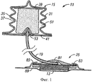
Фиг.1 иллюстрирует вид спереди в поперечном сечении системы лечения пониженным давлением, имеющей сжимаемый вручную насос в соответствии с вариантом выполнения настоящего изобретения, причем указанный сжимаемый вручную насос соединен с возможностью проточного сообщения посредством трубы доставки пониженного давления с магистралью пониженного давления;Figure 1 illustrates a front cross-sectional view of a reduced pressure treatment system having a manually compressible pump in accordance with an embodiment of the present invention, wherein said manually compressible pump is fluidly connected via a reduced pressure delivery pipe to a reduced pressure line;
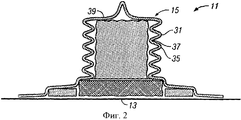
Фиг.2 изображает вид спереди в поперечном сечении системы лечения пониженным давлением, имеющей сжимаемый вручную насос в соответствии с вариантом выполнения настоящего изобретения, причем указанный сжимаемый вручную насос соединен с возможностью проточного сообщения с магистралью пониженного давления;FIG. 2 is a front cross-sectional view of a reduced pressure treatment system having a manually compressible pump in accordance with an embodiment of the present invention, wherein said manually compressible pump is fluidly connected to the reduced pressure manifold;
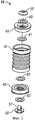
Фиг.3 иллюстрирует разобранный вид в аксонометрии сжимаемого вручную насоса в соответствии с вариантом выполнения настоящего изобретения;Figure 3 illustrates an exploded perspective view of a manually-compressible pump in accordance with an embodiment of the present invention;
Фиг.4 изображает вид в аксонометрии сжимаемого вручную насоса в соответствии с вариантом выполнения настоящего изобретения;Fig. 4 is a perspective view of a manually compressible pump in accordance with an embodiment of the present invention;
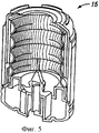
Фиг.5 иллюстрирует поперечное сечение вида в аксонометрии насоса, изображенного на Фиг.4;Figure 5 illustrates a cross section of a perspective view of the pump depicted in Figure 4;
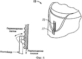
Фиг.6 изображает вид в аксонометрии элемента указания положения, расположенного на сжимаемом вручную насосе, изображенном на Фиг.4, при этом элемент указания положения имеет зубцы и лапки;FIG. 6 is a perspective view of a position indicating member located on a manually compressible pump of FIG. 4, wherein the position indicating member has teeth and tabs;
Фиг.7 иллюстрирует вид спереди элемента указания положения, изображенного на Фиг.6;FIG. 7 illustrates a front view of the position indicating member shown in FIG. 6;
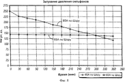
Фиг.8 изображает график результатов испытаний, измеряющих спад давления со временем различных сжимаемых вручную сильфонных насосов, имеющих гибкие стенки с различной величиной жесткости;Fig. 8 is a graph of test results measuring pressure drop over time of various manually compressible bellows pumps having flexible walls with different stiffnesses;
Фиг.9 иллюстрирует повязку для приложения пониженного давления, содержащую клейкую пленку, гидрогель и трубчатый соединитель, в соответствии с вариантом выполнения настоящего изобретения;FIG. 9 illustrates a dressing for applying reduced pressure comprising an adhesive film, a hydrogel, and a tubular connector, in accordance with an embodiment of the present invention;
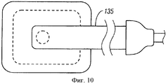
Фиг.10 изображает вид сверху повязки для приложения пониженного давления, изображенной на Фиг.9, проточно сообщающейся с низкопрофильной трубкой доставки пониженного давления;Figure 10 depicts a top view of the bandage for applying reduced pressure, shown in Figure 9, flow-through communication with a low-profile tube delivery of reduced pressure;
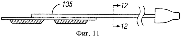
Фиг.11 иллюстрирует вид сбоку повязки для приложения пониженного давления и трубки доставки пониженного давления, изображенных на Фиг.10; иFIG. 11 illustrates a side view of a dressing for applying reduced pressure and a reduced pressure delivery tube shown in FIG. 10; and
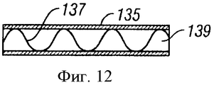
Фиг.12 изображает вид в поперечном сечении трубки доставки пониженного давления, изображенной на Фиг.10.Fig. 12 is a cross-sectional view of the reduced pressure delivery tube shown in Fig. 10.
ПОДРОБНОЕ ОПИСАНИЕ ПРЕДПОЧТИТЕЛЬНОГО ВАРИАНТА ВЫПОЛНЕНИЯDETAILED DESCRIPTION OF THE PREFERRED EMBODIMENT
В последующем детальном описании предпочтительных вариантов выполнения ссылка делается на сопровождающие чертежи, которые являются частью этого описания и на которых посредством иллюстрации показаны конкретные предпочтительные варианты выполнения, в которых может быть осуществлено изобретение. Эти варианты выполнения описаны достаточно подробно, чтобы позволить специалистам осуществить изобретение на практике, при этом также подразумевается, что могут быть использованы другие варианты выполнения, причем логические структурные, механические, электрические и химические изменения могут быть выполнены, не отступая от сущности или объема иллюстративных вариантов выполнения. Чтобы избежать детализации, не нужной для специалистов в этой области техники для осуществления изобретения на практике, в описании может быть опущена конкретная информацию, известная этим специалистам. Поэтому последующее детальное описание не должно восприниматься как ограничивающее, а объем настоящего изобретения определяется только приложенной формулой изобретения.In the following detailed description of preferred embodiments, reference is made to the accompanying drawings, which are part of this description and in which, by way of illustration, specific preferred embodiments are shown in which the invention may be practiced. These embodiments are described in sufficient detail to enable those skilled in the art to practice the invention, and it is also understood that other embodiments may be used, with logical structural, mechanical, electrical, and chemical changes being made without departing from the spirit or scope of the illustrative embodiments. fulfillment. In order to avoid detailing that is not necessary for those skilled in the art to practice the invention, specific information known to those skilled in the art may be omitted from the description. Therefore, the following detailed description should not be construed as limiting, and the scope of the present invention is determined only by the attached claims.
Со ссылкой на Фиг.1 и 3 предложена система 11 доставки пониженного давления в соответствии с вариантом выполнения настоящего изобретения, для того чтобы обеспечивать лечение ткани пониженным давлением путем его подачи к участку 13 ткани пациента. Система подачи пониженного давления содержит сильфонный насос 15, проточно сообщающийся с трубой 19 подачи пониженного давления, которая, в свою очередь, проточно сообщается с низкопрофильной раневой повязкой 25 (интегрированная система, в которой опущена труба подачи пониженного давления, изображена на Фиг.2). Сильфонный насос 15 доставляет пониженное давление к участку 13 ткани через трубу 19 подачи пониженного давления и повязку 25. Пониженное давление поддерживается на участке ткани, что содействует микродеформации ткани на участке ткани и способствует росту новой ткани.With reference to FIGS. 1 and 3, a reduced
Сильфонный насос, предпочтительно имеющий цилиндрическую форму, представляет собой управляемый вручную насос, который имеет гофрированную боковую стенку, или диафрагму 31. Гофрированная боковая стенка содержит выступы 35 и углубления 37, которые облегчают сжатие сильфонного насоса вдоль его продольной оси. Сильфонный насос дополнительно содержит первую торцевую стенку 39 и вторую торцевую стенку 41, интегрально соединенные на противоположных концах гофрированной боковой стенки. В качестве альтернативы сильфонный насос может содержать первую и вторую торцевые крышки или клапанные крышки 43, которые присоединены с возможностью герметизации на противоположных концах гофрированной боковой стенки (см. Фиг.3). Вместе гофрированная боковая стенка и противоположные первая и вторая торцевые стенки формируют эластичный надувной баллон, который ограничивает внутреннюю камеру 51. Объем внутренней камеры 51 является варьируемым. В несжатом положении гофрированная стенка сильфонного насоса находится в своем естественным образом расширенном состоянии (т.е. гофры все еще имеются), при этом объем внутренней камеры имеет максимальную величину. В сжатом положении сильфонный насос был подвергнут сжимающей силе, вызывая, тем самым, уменьшение объема внутренней камеры и увеличение линейной плотности гофров. Когда гофрированная стенка сжата, гофрами прикладывается сила смещения в попытке возвратить гофрированную стену обратно к несжатому положению. Вместо гофров могут быть использованы независимый смещающий элемент, такой как пружина, или упругость негофрированной боковой стенки, чтобы сместить боковую стенку к несжатому положению.The bellows pump, preferably having a cylindrical shape, is a manually operated pump that has a corrugated side wall or
Соединительное отверстие 53 предпочтительно расположено на одной из торцевых стенок сильфонного насоса, чтобы обеспечить проточное сообщение внутренней камеры с трубой подачи пониженного давления. Зонтичный клапан 55 и двухстворчатый клапан 57 функционально соединены с соединительным отверстием, чтобы выборочно впускать или удалять текучие среды из внутренней камеры. Двухстворчатый клапан обеспечивает однонаправленное проточное сообщение от трубы подачи пониженного давления к внутренней камере. Зонтичный клапан обеспечивает однонаправленное проточное сообщение от внутренней камеры к окружающей атмосфере, окружающей сильфонный насос. Аналогичный зонтичный клапан расположен в торцевой стенке напротив торцевой стенки, в которой выполнено соединительное отверстие.The connecting
Со ссылкой более конкретно на Фиг.3 гидрофобный фильтр 61 и фильтр 63, поглощающий запахи (например, фильтр с активированным углем) размещены около зонтичного клапана. Гидрофобный фильтр предотвращает удаление через зонтичный клапан любых жидкостей, находящихся во внутренней камере. Фильтр, поглощающий запахи, устраняет запахи, связанные с любыми газами, которые удаляются из внутренней камеры через зонтичные клапаны.With reference more specifically to FIG. 3, a
Клапаны, связанные с сильфонным насосом, выборочно обеспечивают обмен текучей средой с внутренней камерой. Когда сильфонный насос первоначально помещен в сжатое положение (вызванное приложением вручную силы сжатия к концевым стенкам), газообразные текучие среды, находящиеся внутри внутренней камеры, удаляются через один или оба зонтичных клапана. Газообразные текучие среды проходят через фильтр, поглощающий запахи, до того, как они выходят из внутренней камеры. Когда гофры (сильфон) находятся в сжатом положении, гофрированная стенка, которая была упруго деформирована, пытается восстановить свое несжатое состояние. По мере того, как гофрированная стенка перемещается назад к своему несжатому состоянию, объем внутренней камеры увеличивается, что приводит к уменьшению давления во внутренней камере (внутренняя камера работает как закрытая система P1*V1=P2*V2). Разность давлений между внутренней камерой и окружающей атмосферой (то есть давлением на участке ткани) приводит к втягиванию газообразных и жидких текучих сред из трубы подачи пониженного давления и раневой повязки во внутреннюю камеру. Это затем приводит к созданию пониженного давления на участке ткани. С должным образом герметизированной раневой повязкой это пониженное давление может поддерживаться на участке ткани. Текучие среды, оттянутые из участка ткани, входят во внутреннюю камеру через двухстворчатый клапан. Двухстворчатый клапан препятствует тому, чтобы эти текучие среды выходили из внутренней камеры.The valves associated with the bellows pump selectively allow fluid to exchange with the inner chamber. When the bellows pump is initially placed in a compressed position (caused by the application of a manual compression force to the end walls), gaseous fluids inside the inner chamber are removed through one or both of the umbrella valves. Gaseous fluids pass through an odor-absorbing filter before they exit the inner chamber. When the corrugations (bellows) are in a compressed position, the corrugated wall, which has been elastically deformed, is trying to restore its uncompressed state. As the corrugated wall moves back to its uncompressed state, the volume of the inner chamber increases, which leads to a decrease in pressure in the inner chamber (the inner chamber acts as a closed system P1 * V1 = P2 * V2). The pressure difference between the inner chamber and the surrounding atmosphere (i.e. pressure at the tissue site) causes gaseous and liquid fluids to be drawn from the reduced pressure supply pipe and the wound dressing into the inner chamber. This then leads to the creation of reduced pressure on the tissue site. With a properly sealed wound dressing, this reduced pressure can be maintained at the tissue site. Fluids drawn from the tissue site enter the inner chamber through a butterfly valve. A butterfly valve prevents these fluids from exiting the inner chamber.
Одно назначение сильфонного устройства состоит в том, чтобы подавать и поддерживать пониженное давление на участке ткани, пока внутренняя камера полностью не заполнится жидким эксудатом раны. В некоторых случаях сильфонный насос может достигнуть несжатого положения (после начального запуска) без того, чтобы внутренняя камера была полностью заполнена эксудатом раны и другими жидкостями. В этом случае сильфонный насос может быть вновь запущен, снова оказывая силу сжатия на концевые стенки сильфонного насоса. По мере того, как объем внутренней камеры снова уменьшается, газообразные текучие среды во внутренней камере удаляются через зонтичные клапаны. Гидрофобные фильтры предотвращают удаление жидкостей из внутренней камеры. Поскольку сильфонный насос имеет больше одного зонтичного клапана, насос может быть вновь запущен независимо от своей ориентации.One purpose of the bellows device is to apply and maintain a reduced pressure on the tissue site until the inner chamber is completely filled with liquid exudate of the wound. In some cases, the bellows pump may reach an uncompressed position (after the initial start) without the inner chamber being completely filled with wound exudate and other fluids. In this case, the bellows pump can be restarted, again exerting a compressive force on the end walls of the bellows pump. As the volume of the inner chamber decreases again, gaseous fluids in the inner chamber are removed through the umbrella valves. Hydrophobic filters prevent the removal of liquids from the inner chamber. Since the bellows pump has more than one umbrella valve, the pump can be restarted regardless of its orientation.
Сильфонный насос может содержать абсорбирующую пену, расположенную во внутренней камере и предназначенную для поглощения эксудата раны и других текучих сред, которые удалены от участка ткани. Дополнительно внутри сильфонного насоса может быть предусмотрена односторонняя мембрана, предназначенная для предотвращения обратного потока любых текучих сред из внутренней камеры.The bellows pump may contain an absorbent foam located in the inner chamber and designed to absorb exudate wounds and other fluids that are removed from the tissue site. Additionally, a one-way diaphragm may be provided inside the bellows pump to prevent the backflow of any fluids from the inner chamber.
Со ссылкой на Фиг.4 и 5 в одном варианте выполнения настоящего изобретения сильфонный насос может содержать жесткий кожух 71, который имеет гофрированную стенку. Торцевая крышка 73 может быть с возможностью скольжения расположена на кожухе и размещена сверху гофрированной стенки таким образом, чтобы гофрированная стена могла быть сжата путем нажатия на торцевую крышку. Указывающий положение элемент, имеющий стопор 75 и язычок 77, может быть функционально связан с кожухом и торцевой крышкой, чтобы обеспечить слышимый и осязательный «щелчок», когда гофрированная стена достигает сжатого положения. В качестве альтернативы, со ссылкой на Фиг.6-8, зубцы или стопоры и лапка могут быть функционально связаны с кожухом и торцевой крышкой, чтобы создавать звук трещотки, когда сильфонный насос запускается. Каждый отдельный «щелчок» может быть указанием на конкретную разность давлений, которую сильфонный насос способен создать в данный конкретный момент времени. Звуковые индикаторы могут также сопровождаться визуальным индикатором 79, чтобы сообщать пользователю, какая величина разности давлений может быть обеспечена.With reference to FIGS. 4 and 5, in one embodiment of the present invention, the bellows pump may comprise a
Со ссылкой на Фиг.8 было выполнено испытание для измерения спада давления, связанного с сильфонными насосами, имеющими гофрированные стенки, изготовленные из материалов различных величин твердости. Тогда как результаты указывают на то, что материал, имеющий показатель твердости по Шору, равный 65, испытывает меньший спад давления, это происходит частично из-за улучшенной герметичности раневой повязки. Было обнаружено, что материал, имеющий показатель твердости по Шору, равный 65, способен обеспечить разность давлений между 125 и 150 мм рт.ст. Эти уровни давления могут поддерживаться в течение по меньшей мере шести часов. Для более высоких давлений могут быть использованы более твердые материалы (такой как материал, имеющий показатель твердости по Шору, равный 85). Используя этот тип конструкции насоса, можно создать давление порядка 250 мм рт.ст., и даже возможно выше 400 мм рт.ст.With reference to FIG. 8, a test was performed to measure the pressure drop associated with bellows pumps having corrugated walls made of materials of various hardness values. While the results indicate that a material having a Shore hardness value of 65 experiences a lower pressure drop, this is partly due to improved tightness of the wound dressing. It was found that a material having a Shore hardness value of 65 is capable of providing a pressure difference between 125 and 150 mmHg. These pressure levels can be maintained for at least six hours. For higher pressures, harder materials can be used (such as a material having a Shore hardness value of 85). Using this type of pump design, it is possible to create a pressure of the order of 250 mmHg, and even possibly above 400 mmHg.
Следует отметить, что хотя и описан сильфонный насос, любой насос, которым управляют вручную, включая, без ограничений, диафрагменный насос (насос-лягушка) или поршневой насос, может заменить сильфонный насос. В некоторых ситуациях может быть желательным запускать (или приводить в состояние готовности) насос, используя электроэнергию, но в большинстве случаев насос должен быть готов к запуску пользователем вручную без электроэнергии.It should be noted that although a bellows pump has been described, any manually operated pump, including but not limited to a diaphragm pump (frog pump) or piston pump, can replace a bellows pump. In some situations, it may be desirable to start (or put on standby) the pump using electricity, but in most cases the pump should be ready to be started manually by the user without electricity.
Со ссылкой снова на Фиг.1 низкопрофильная раневая повязка включает трубчатый соединитель 81, кольцо 83 гидрогеля и пленку 85. Соединитель трубы расположен выше магистрали пониженного давления таким образом, чтобы отверстие соединителя трубы находилось в проточном сообщении с магистралью. Кольцо гидрогеля расположено между соединителем трубы и поверхностью 89 ткани пациента, смежной с участком ткани. Пленка, предпочтительно выполненная из полиуретана, с возможностью клейкого соединения приложена к соединителю трубы и поверхности ткани пациента, чтобы зафиксировать повязку на пациенте и обеспечить герметизацию между повязкой и пациентом. Герметизирующие элементы повязки дополнительно усилены кольцом гидрогеля, которое не только герметизирует поверхность ткани пациента, но также и препятствует тому, чтобы поверхности ткани во время использования повязки было нанесено повреждение.With reference again to FIG. 1, the low profile wound dressing includes a
Магистраль предпочтительно представляет собой пенопласт с открытыми порами. Магистраль обеспечивает распределение пониженного давления, создаваемого сильфонным насосом. Следует отметить, что вместо пенопласта с открытыми порами может быть использован любой материал, способный к распределению пониженного давления.The line is preferably an open-cell foam. The line ensures the distribution of the reduced pressure generated by the bellows pump. It should be noted that instead of open-cell foam, any material capable of distributing reduced pressure can be used.
Со ссылкой на Фиг.9 с системой подачи пониженного давления может также использоваться интегрированная раневая повязка 111. Интегрированная раневая повязка содержит большую область гидрогеля 113, расположенную на пленке 115. Пленка предпочтительно содержит адгезивное покрытие 117, служащее вспомогательным герметиком к гидрогелю. Отверстие 121 расположено в пленке, а отверстие 123 расположено в гидрогеле, чтобы обеспечить сквозное соединение соответствующего трубчатого соединителя 125.With reference to FIG. 9, an integrated wound dressing 111 may also be used with the reduced pressure delivery system. The integrated wound dressing comprises a large area of
Со ссылкой на Фиг.10-12 в другом варианте выполнения раневой повязки, с раневой повязкой непосредственно соединена ультранизкопрофильная труба 135 подачи пониженного давления. Труба является достаточно плоской и прямоугольной в поперечном сечении, что значительно уменьшает толщину всей раневой повязки, когда она соединена с трубой. Предпочтительно внутри трубки предусмотрены гофры 137 (см. Фиг.12), чтобы противодействовать разрушению трубы под давлением. Труба и гофры могут быть получены экструзией вместе в одном производственном процессе или же могут быть собраны вместе после отдельных производственных процессов. Между гофрами ограничены проточные каналы 139. Труба предпочтительно соединена с пленкой путем заливки гидрогеля на пленку и трубу и обеспечения их склеивания.With reference to FIGS. 10-12, in another embodiment of the wound dressing, an ultra-low profile reduced
Из предшествующего описания должно быть очевидно, что было показано изобретение, имеющее существенные преимущества. Хотя изобретение было показано только в нескольких из его форм, оно не только не ограничено этими формами, но также возможны различные видоизменения и модификации, не отступающие от сущности изобретения.From the foregoing description, it should be apparent that an invention having significant advantages has been shown. Although the invention has been shown in only a few of its forms, it is not only not limited to these forms, but various modifications and modifications are possible without departing from the essence of the invention.
Claims (17)
жесткий кожух;
торцевую крышку, расположенную с возможностью скольжения на кожухе;
внутреннюю камеру, расположенную между торцевой крышкой и кожухом, причем объем внутренней камеры является переменным в зависимости от положения торцевой крышки внутри кожуха, при этом торцевая крышка выполнена с возможностью перемещения путем скольжения между несжатым положением, в котором объем внутренней камеры имеет максимальную величину, и сжатым положением, в котором объем внутренней камеры имеет минимальную величину;
указывающий положение элемент, связанный с торцевой крышкой и кожухом, предназначенный для указания положения торцевой крышки относительно кожуха в заранее заданных положениях между несжатым положением и сжатым положением,
причем указывающий положение элемент дополнительно содержит
элемент, выбранный из множества зубцов и лапки, расположенной на кожухе; и оставшийся элемент из множества зубцов и лапки, расположенный на торцевой крышке, причем множество зубцов и лапка выполнены, чтобы зацепляться друг с другом для указания положения торцевой крышки относительно кожуха в заранее заданных положениях между несжатым положением и сжатым положением.1. Manually activated system of treatment of low blood pressure containing
hard cover;
an end cover slidably located on the casing;
an inner chamber located between the end cap and the casing, the volume of the inner chamber being variable depending on the position of the end cap inside the casing, while the end cap is movable by sliding between the uncompressed position in which the volume of the inner chamber has a maximum value and compressed a position in which the volume of the inner chamber has a minimum value;
a position indicating element associated with the end cap and the casing, designed to indicate the position of the end cap relative to the casing in predetermined positions between the uncompressed position and the compressed position,
wherein the position indicating element further comprises
an element selected from many teeth and paws located on the casing; and the remaining member of the plurality of teeth and paws located on the end cap, and the plurality of teeth and paw are arranged to engage with each other to indicate the position of the end cap relative to the casing in predetermined positions between the uncompressed position and the compressed position.
эластичный надувной баллон, расположенный внутри кожуха и ограниченный торцевой крышкой с формированием внутренней камеры;
причем эластичный надувной баллон содержит гибкую боковую стенку, имеющую большое количество гофров;
при этом гофры, когда сжаты, служат в качестве смещающего элемента для смещения торцевой крышки к несжатому положению.5. The system of claim 4, further comprising
an elastic inflatable balloon located inside the casing and bounded by an end cap with the formation of an inner chamber;
moreover, the flexible inflatable balloon contains a flexible side wall having a large number of corrugations;
while the corrugations, when compressed, serve as a biasing element for displacing the end cap to an uncompressed position.
магистраль пониженного давления, предназначенную для размещения рядом с участком ткани;
сжимаемый вручную насос, находящийся в сообщении посредством текучей среды с магистралью пониженного давления, чтобы подавать пониженное давление к участку ткани, при этом сжимаемый вручную насос содержит:
гибкую и сжимаемую боковую стенку;
кожух, предназначенный для вмещения боковой стенки и расположенный вокруг нее;
первую и вторую торцевые крышки, присоединенные в противоположных концах боковой стенки для формирования внутренней камеры, ограниченной боковой стенкой и торцевыми крышками, при этом внутренняя камера имеет объем, который изменяется от максимальной величины, когда боковая стенка находится в несжатом положении, до минимальной величины, когда боковая стенка находится в сжатом положении;
соединительное отверстие, расположенное в одной из первой и второй торцевых крышах для обеспечения сообщения посредством текучей среды между внутренней камерой и магистралью пониженного давления;
односторонний клапан, расположенный в одной из первой торцевой крышки, второй торцевой крышки и боковой стенки для обеспечения выпуска текучей среды из внутренней камеры,
гидрофобный фильтр, находящийся в сообщении с односторонним клапаном, предназначенный для воспрепятствования выхода жидкостей из внутренней камеры через односторонний клапан; и
фильтр, удаляющий запахи, находящийся в сообщении с односторонним клапаном, предназначенный для устранения запахов, связанных с газами, удаляемыми через односторонний клапан, а также
указывающий положение элемент, связанный с кожухом и по меньшей мере с одной из торцевых крышек, чтобы указывать положение боковой стенки в заранее заданных положениях между несжатым положением и сжатым положением, причем
указывающий положение элемент дополнительно содержит
элемент, выбранный из множества зубцов и лапки, расположенный на кожухе; и оставшийся элемент из множества зубцов и лапки, расположенный на указанной по меньшей мере одной торцевой крышке, при этом множество зубцов и лапка выполнены с возможностью зацепления друг с другом для индикации положения боковой стенки в заранее заданных положениях между несжатым положением и сжатым положением.6. A manually activated low-pressure treatment system comprising
low-pressure line, designed to be placed next to the tissue site;
a manually compressible pump in fluid communication with a reduced pressure line to supply reduced pressure to a tissue site, the manually compressible pump comprising:
flexible and compressible side wall;
a casing designed to contain the side wall and located around it;
first and second end caps attached at opposite ends of the side wall to form an inner chamber bounded by the side wall and end caps, the inner chamber having a volume that changes from a maximum value when the side wall is in an uncompressed position to a minimum value when the side wall is in a compressed position;
a connecting hole located in one of the first and second end roofs to provide communication through the fluid between the inner chamber and the line of reduced pressure;
a one-way valve located in one of the first end cap, the second end cap, and the side wall to allow fluid to escape from the inner chamber,
a hydrophobic filter in communication with a one-way valve, designed to prevent the exit of liquids from the inner chamber through a one-way valve; and
an odor filter in communication with the one-way valve, designed to eliminate odors associated with gases removed through the one-way valve, and
a position indicating element associated with the casing and at least one of the end caps to indicate the position of the side wall in predetermined positions between the uncompressed position and the compressed position, wherein
the position indicating element further comprises
an element selected from many teeth and paws located on the casing; and the remaining member of the plurality of teeth and paws located on said at least one end cover, wherein the plurality of teeth and paw are engaged with each other to indicate the position of the side wall in predetermined positions between the uncompressed position and the compressed position.
боковая стенка включает большое количество гофров, которые, когда сжаты, оказывают силу смещения, которая смещает боковую стенку к несжатому положению.7. The system according to claim 6, in which
the side wall includes a large number of corrugations which, when compressed, exert a biasing force that biases the side wall to an uncompressed position.
второй односторонний клапан, расположенный во второй торцевой крышке;
при этом наличие одностороннего клапана в каждой торцевой крышке независимо от ориентации сжимаемого вручную насоса обеспечивает повторное сжатие боковой стенки после того, как во внутренней камере от участка ткани была собрана жидкость.9. The system of claim 8, in which the manually compressible pump further comprises
a second one-way valve located in the second end cap;
however, the presence of a one-way valve in each end cap, regardless of the orientation of the manually compressible pump, provides for re-compression of the side wall after fluid has been collected in the inner chamber from the tissue site.
абсорбирующую пену, расположенную во внутренней камере для поглощения текучей среды, оттянутой из участка ткани сжимаемым вручную насосом.10. The system of claim 6, wherein the manually compressible pump further comprises
an absorbent foam located in the inner chamber for absorbing a fluid drawn from a tissue site by a manually compressible pump.
осуществление сжатия вручную гибкой диафрагмы для уменьшения объема камеры, сообщающейся посредством текучей среды с участком ткани;
указание звуковым, визуальным или тактильным образом места расположения гибкой диафрагмы в положении между несжатым положением и сжатым положением;
определение пониженного давления, создаваемого сжатой гибкой диафрагмой, основываясь на указанном положении; и
подачу пониженного давления к участку ткани.12. A method for activating a low pressure therapeutic pump, comprising
manually compressing the flexible diaphragm to reduce the volume of the chamber in fluid communication with the tissue site;
sound, visual or tactile indication of the location of the flexible diaphragm in the position between the uncompressed position and the compressed position;
determining a reduced pressure created by a compressed flexible diaphragm based on a specified position; and
supply of reduced pressure to the tissue site.
источник пониженного давления; магистраль пониженного давления, предназначенную для расположения рядом с участком ткани; и плоскую трубу подачи пониженного давления, подсоединенную с возможностью сообщения посредством текучей среды между источником пониженного давления и магистралью пониженного давления, при этом труба имеет прямоугольное поперечное сечение и большое количество гофров внутри трубы для предотвращения разрушения трубы во время подачи пониженного давления.16. A low-profile low-pressure treatment system comprising
source of reduced pressure; low pressure line, designed to be located next to the tissue site; and a flat pipe for supplying reduced pressure, which is fluidly connected between the source of reduced pressure and the line of reduced pressure, the pipe having a rectangular cross-section and a large number of corrugations inside the pipe to prevent destruction of the pipe during the supply of reduced pressure.
гибкую и сжимаемую боковую стенку;
первую и вторую торцевые крышки, присоединенные в противоположных концах боковой стенки для формирования внутренней камеры, ограниченной боковой стенкой и торцевыми крышками, при этом внутренняя камера имеет объем, который изменяется от максимальной величины, когда боковая стенка находится в несжатом положении, до минимальной величины, когда боковая стенка находится в сжатом положении;
соединительное отверстие, расположенное в одной из первой и второй торцевых крышках для обеспечения сообщения посредством текучей среды между внутренней камерой и магистралью пониженного давления;
односторонний клапан, расположенный в одной из первой торцевой крышки, второй торцевой крышки и боковой стенки для обеспечения выпуска текучей среды из внутренней камеры;
гидрофобный фильтр, находящийся в сообщении с односторонним клапаном, предназначенный для воспрепятствования выхода жидкостей из внутренней камеры через односторонний клапан; и
фильтр, удаляющий запахи, находящийся в сообщении с односторонним клапаном, предназначенный для устранения запахов, связанных с газами, удаляемыми через односторонний клапан. 17. The system according to clause 16, in which the source of reduced pressure is a manually compressible pump, while the system contains
flexible and compressible side wall;
first and second end caps attached at opposite ends of the side wall to form an inner chamber bounded by the side wall and end caps, the inner chamber having a volume that changes from a maximum value when the side wall is in an uncompressed position to a minimum value when the side wall is in a compressed position;
a connecting hole located in one of the first and second end caps to provide fluid communication between the inner chamber and the reduced pressure line;
a one-way valve located in one of the first end cap, the second end cap, and the side wall to allow fluid to escape from the inner chamber;
a hydrophobic filter in communication with a one-way valve, designed to prevent the exit of liquids from the inner chamber through a one-way valve; and
an odor filter in communication with the one-way valve, designed to eliminate odors associated with gases removed through the one-way valve.
Applications Claiming Priority (2)
| Application Number | Priority Date | Filing Date | Title |
|---|---|---|---|
| US85149406P | 2006-10-13 | 2006-10-13 | |
| US60/851,494 | 2006-10-13 |
Publications (2)
| Publication Number | Publication Date |
|---|---|
| RU2009111101A RU2009111101A (en) | 2010-11-20 |
| RU2417110C2 true RU2417110C2 (en) | 2011-04-27 |
Family
ID=39314621
Family Applications (1)
| Application Number | Title | Priority Date | Filing Date |
|---|---|---|---|
| RU2009111101/14A RU2417110C2 (en) | 2006-10-13 | 2007-10-15 | Low pressure feed system having manually activated pump for mild wound healing |
Country Status (15)
| Country | Link |
|---|---|
| US (5) | US8007257B2 (en) |
| EP (3) | EP2079507B1 (en) |
| JP (3) | JP4927173B2 (en) |
| KR (1) | KR101151489B1 (en) |
| CN (4) | CN105233350B (en) |
| AU (2) | AU2007313282B2 (en) |
| BR (1) | BRPI0715320A2 (en) |
| CA (3) | CA2776011C (en) |
| IL (1) | IL197984A0 (en) |
| MX (1) | MX2009003870A (en) |
| NO (1) | NO20091288L (en) |
| RU (1) | RU2417110C2 (en) |
| TW (1) | TWI370000B (en) |
| WO (1) | WO2008048527A2 (en) |
| ZA (1) | ZA200901941B (en) |
Cited By (1)
| Publication number | Priority date | Publication date | Assignee | Title |
|---|---|---|---|---|
| US20220000672A1 (en) * | 2015-05-18 | 2022-01-06 | Smith & Nephew Plc | Heat-assisted pumping systems for use in negative pressure wound therapy |
Families Citing this family (203)
| Publication number | Priority date | Publication date | Assignee | Title |
|---|---|---|---|---|
| GB0224986D0 (en) | 2002-10-28 | 2002-12-04 | Smith & Nephew | Apparatus |
| GB0325129D0 (en) | 2003-10-28 | 2003-12-03 | Smith & Nephew | Apparatus in situ |
| US8636721B2 (en) | 2003-11-20 | 2014-01-28 | Henry M. Jackson Foundation For The Advancement Of Military Medicine, Inc. | Portable hand pump for evacuation of fluids |
| US7909805B2 (en) | 2004-04-05 | 2011-03-22 | Bluesky Medical Group Incorporated | Flexible reduced pressure treatment appliance |
| US10058642B2 (en) | 2004-04-05 | 2018-08-28 | Bluesky Medical Group Incorporated | Reduced pressure treatment system |
| US8062272B2 (en) | 2004-05-21 | 2011-11-22 | Bluesky Medical Group Incorporated | Flexible reduced pressure treatment appliance |
| US8337475B2 (en) | 2004-10-12 | 2012-12-25 | C. R. Bard, Inc. | Corporeal drainage system |
| US8298197B2 (en) * | 2005-06-29 | 2012-10-30 | Elof Eriksson | Wound chamber for limb |
| EP1922045B1 (en) | 2005-09-07 | 2012-11-07 | Tyco Healthcare Group LP | Self contained wound dressing with micropump |
| AU2006287460A1 (en) | 2005-09-07 | 2007-03-15 | Tyco Healthcare Group Lp | Wound dressing with vacuum reservoir |
| US7779625B2 (en) | 2006-05-11 | 2010-08-24 | Kalypto Medical, Inc. | Device and method for wound therapy |
| DE602007004546D1 (en) | 2006-09-28 | 2010-03-18 | Tyco Healthcare | Portable wound therapy system |
| RU2417110C2 (en) | 2006-10-13 | 2011-04-27 | КейСиАй Лайсензинг Инк. | Low pressure feed system having manually activated pump for mild wound healing |
| US8287507B2 (en) | 2006-10-13 | 2012-10-16 | Kci Licensing, Inc. | Reduced pressure indicator for a reduced pressure source |
| JP5345555B2 (en) | 2007-02-09 | 2013-11-20 | ケーシーアイ ライセンシング インコーポレイテッド | System and method for applying reduced pressure to a tissue site |
| WO2008112304A1 (en) * | 2007-03-14 | 2008-09-18 | The Board Of Trustees Of The Leland Stanford Junior University | Devices and methods for application of reduced pressure therapy |
| US8083712B2 (en) * | 2007-03-20 | 2011-12-27 | Neogen Technologies, Inc. | Flat-hose assembly for wound drainage system |
| AU2008246934A1 (en) * | 2007-05-07 | 2008-11-13 | Carmeli Adahan | Suction system |
| EP2157948B1 (en) | 2007-05-24 | 2017-02-15 | Applied Tissue Technologies Llc | Wound treatment device employing negative pressure |
| GB0712763D0 (en) | 2007-07-02 | 2007-08-08 | Smith & Nephew | Apparatus |
| GB0715212D0 (en) | 2007-08-06 | 2007-09-12 | Smith & Nephew | Apparatus |
| AU2008310622B2 (en) | 2007-10-11 | 2014-01-09 | Solventum Intellectual Properties Company | Closed incision negative pressure wound therapy device and methods of use |
| TWI340653B (en) | 2007-11-09 | 2011-04-21 | Ind Tech Res Inst | Detachable pump and the negative pressure wound therapy system using the same |
| WO2009067711A2 (en) | 2007-11-21 | 2009-05-28 | T.J. Smith & Nephew, Limited | Suction device and dressing |
| GB0722820D0 (en) | 2007-11-21 | 2008-01-02 | Smith & Nephew | Vacuum assisted wound dressing |
| CA2705896C (en) | 2007-11-21 | 2019-01-08 | Smith & Nephew Plc | Wound dressing |
| HUE043133T2 (en) | 2007-11-21 | 2019-07-29 | Smith & Nephew | Wound dressing |
| GB2455962A (en) | 2007-12-24 | 2009-07-01 | Ethicon Inc | Reinforced adhesive backing sheet, for plaster |
| ATE546174T1 (en) | 2008-01-08 | 2012-03-15 | Bluesky Medical Group Inc | CONTINUOUS VARIABLE NEGATIVE PRESSURE WOUND TREATMENT AND CONTROL METHOD THEREOF |
| EP2586470B1 (en) | 2008-02-14 | 2020-07-15 | KCI Licensing, Inc. | Devices for treatment of damaged tissue |
| GB0803564D0 (en) | 2008-02-27 | 2008-04-02 | Smith & Nephew | Fluid collection |
| SG174765A1 (en) | 2008-03-05 | 2011-10-28 | Kci Licensing Inc | Dressing and method for applying reduced pressure to and collecting andstoring fluid from a tissue site |
| US9033942B2 (en) | 2008-03-07 | 2015-05-19 | Smith & Nephew, Inc. | Wound dressing port and associated wound dressing |
| EP2257320A2 (en) | 2008-03-12 | 2010-12-08 | Bluesky Medical Group Inc. | Negative pressure dressing and method of using same |
| US8152785B2 (en) | 2008-03-13 | 2012-04-10 | Tyco Healthcare Group Lp | Vacuum port for vacuum wound therapy |
| GB0804654D0 (en) * | 2008-03-13 | 2008-04-16 | Smith & Nephew | Vacuum closure device |
| CN103893846B (en) | 2008-05-02 | 2017-05-24 | 凯希特许有限公司 | Manually-actuated reduced pressure pump having regulated pressure capabilities |
| GB0808376D0 (en) | 2008-05-08 | 2008-06-18 | Bristol Myers Squibb Co | Wound dressing |
| US8414519B2 (en) | 2008-05-21 | 2013-04-09 | Covidien Lp | Wound therapy system with portable container apparatus |
| US8177763B2 (en) | 2008-09-05 | 2012-05-15 | Tyco Healthcare Group Lp | Canister membrane for wound therapy system |
| US8007481B2 (en) | 2008-07-17 | 2011-08-30 | Tyco Healthcare Group Lp | Subatmospheric pressure mechanism for wound therapy system |
| US10912869B2 (en) | 2008-05-21 | 2021-02-09 | Smith & Nephew, Inc. | Wound therapy system with related methods therefor |
| CA2726814C (en) * | 2008-05-27 | 2014-05-20 | Kalypto Medical, Inc. | Control unit with pump module for a negative pressure wound therapy device |
| CA2726815C (en) * | 2008-05-27 | 2016-07-05 | Kalypto Medical, Inc. | Negative pressure wound therapy device |
| GB2461261A (en) * | 2008-06-23 | 2009-12-30 | Carmeli Adahan | A device for vacuum treatment of damaged tissue |
| EP2977068B1 (en) | 2008-07-11 | 2017-10-11 | KCI Licensing, Inc. | Manually-actuated, reduced-pressure systems for treating wounds |
| US8827983B2 (en) | 2008-08-21 | 2014-09-09 | Smith & Nephew, Inc. | Sensor with electrical contact protection for use in fluid collection canister and negative pressure wound therapy systems including same |
| US9414968B2 (en) | 2008-09-05 | 2016-08-16 | Smith & Nephew, Inc. | Three-dimensional porous film contact layer with improved wound healing |
| GB0817796D0 (en) | 2008-09-29 | 2008-11-05 | Convatec Inc | wound dressing |
| EP3388093B1 (en) * | 2008-11-14 | 2020-05-20 | KCI Licensing, Inc. | Fluid pouch, system, and method for storing fluid from a tissue site |
| EP2358425B1 (en) | 2008-11-25 | 2014-11-12 | Spiracur Inc. | Device for delivery of reduced pressure to body surfaces |
| GB2465797B (en) * | 2008-11-28 | 2011-04-27 | Ind Tech Res Inst | Detachable pump and the negative pressure wound therapy system using the same |
| US8721629B2 (en) | 2008-12-02 | 2014-05-13 | Kci Licensing, Inc. | System and method for mechanical closure of wounds |
| TWI396525B (en) * | 2008-12-19 | 2013-05-21 | Ind Tech Res Inst | Apparatus for fluid collection |
| WO2010080907A1 (en) | 2009-01-07 | 2010-07-15 | Spiracur Inc. | Reduced pressure therapy of the sacral region |
| GB0900423D0 (en) | 2009-01-12 | 2009-02-11 | Smith & Nephew | Negative pressure device |
| WO2010102146A1 (en) * | 2009-03-04 | 2010-09-10 | Spiracur Inc. | Devices and methods to apply alternating level of reduced pressure to tissue |
| EP2416816B1 (en) | 2009-04-10 | 2014-10-15 | Spiracur Inc. | Methods and devices for applying closed incision negative pressure wound therapy |
| US8444614B2 (en) | 2009-04-10 | 2013-05-21 | Spiracur, Inc. | Methods and devices for applying closed incision negative pressure wound therapy |
| US10792404B2 (en) | 2009-04-10 | 2020-10-06 | Kci Licensing, Inc. | Methods and devices for applying closed incision negative pressure wound therapy |
| EP2419157A4 (en) | 2009-04-17 | 2018-01-03 | Kalypto Medical, Inc. | Negative pressure wound therapy device |
| US20100324516A1 (en) | 2009-06-18 | 2010-12-23 | Tyco Healthcare Group Lp | Apparatus for Vacuum Bridging and/or Exudate Collection |
| US20110066123A1 (en) | 2009-09-15 | 2011-03-17 | Aidan Marcus Tout | Medical dressings, systems, and methods employing sealants |
| US8529526B2 (en) * | 2009-10-20 | 2013-09-10 | Kci Licensing, Inc. | Dressing reduced-pressure indicators, systems, and methods |
| EP2515961B1 (en) | 2009-12-22 | 2019-04-17 | Smith & Nephew, Inc. | Apparatuses for negative pressure wound therapy |
| DE102009060596A1 (en) * | 2009-12-23 | 2011-06-30 | Paul Hartmann Aktiengesellschaft, 89522 | Connection device for use in the vacuum treatment of wounds |
| DE102010006273A1 (en) * | 2010-01-26 | 2011-07-28 | Paul Hartmann Aktiengesellschaft, 89522 | Connection device for use in the vacuum treatment of wounds |
| DE102010006272A1 (en) * | 2010-01-26 | 2011-07-28 | Paul Hartmann AG, 89522 | connection device |
| ITMI20100237A1 (en) * | 2010-02-17 | 2011-08-18 | Eurosets Srl | MANUAL BELLOWS PUMP FOR THE CREATION OF VACUUM IN A RIGID CONTAINER, PARTICULARLY FOR MEDICAL USE. |
| US8430867B2 (en) * | 2010-03-12 | 2013-04-30 | Kci Licensing, Inc. | Reduced-pressure dressing connection pads, systems, and methods |
| US8814842B2 (en) | 2010-03-16 | 2014-08-26 | Kci Licensing, Inc. | Delivery-and-fluid-storage bridges for use with reduced-pressure systems |
| US9061095B2 (en) | 2010-04-27 | 2015-06-23 | Smith & Nephew Plc | Wound dressing and method of use |
| USRE48117E1 (en) | 2010-05-07 | 2020-07-28 | Smith & Nephew, Inc. | Apparatuses and methods for negative pressure wound therapy |
| US8299117B2 (en) | 2010-06-16 | 2012-10-30 | Metabolex Inc. | GPR120 receptor agonists and uses thereof |
| US9265665B2 (en) | 2010-07-19 | 2016-02-23 | Kci Licensing, Inc. | Inflatable off-loading wound dressing assemblies, systems, and methods |
| US8753322B2 (en) | 2010-08-10 | 2014-06-17 | Spiracur Inc. | Controlled negative pressure apparatus and alarm mechanism |
| US11291760B2 (en) | 2010-08-10 | 2022-04-05 | Kci Licensing, Inc. | Controlled negative pressure apparatus and alarm mechanism |
| US8795246B2 (en) * | 2010-08-10 | 2014-08-05 | Spiracur Inc. | Alarm system |
| GB201015656D0 (en) | 2010-09-20 | 2010-10-27 | Smith & Nephew | Pressure control apparatus |
| GB201020236D0 (en) | 2010-11-30 | 2011-01-12 | Convatec Technologies Inc | A composition for detecting biofilms on viable tissues |
| US9526816B2 (en) | 2010-12-08 | 2016-12-27 | Convatec Technologies Inc. | Wound exudate monitor accessory |
| WO2012078781A1 (en) | 2010-12-08 | 2012-06-14 | Convatec Technologies Inc. | Integrated system for assessing wound exudates |
| DK2648795T3 (en) * | 2010-12-08 | 2023-03-27 | Convatec Technologies Inc | System for removing exudates from a wound site |
| USD714433S1 (en) | 2010-12-22 | 2014-09-30 | Smith & Nephew, Inc. | Suction adapter |
| US9050398B2 (en) | 2010-12-22 | 2015-06-09 | Smith & Nephew, Inc. | Apparatuses and methods for negative pressure wound therapy |
| GB2488749A (en) | 2011-01-31 | 2012-09-12 | Systagenix Wound Man Ip Co Bv | Laminated silicone coated wound dressing |
| CN106974683B (en) | 2011-02-04 | 2020-02-21 | 马萨诸塞州大学 | Negative pressure wound closure device |
| US9421132B2 (en) | 2011-02-04 | 2016-08-23 | University Of Massachusetts | Negative pressure wound closure device |
| GB201106491D0 (en) | 2011-04-15 | 2011-06-01 | Systagenix Wound Man Ip Co Bv | Patterened silicone coating |
| US9058634B2 (en) | 2011-05-24 | 2015-06-16 | Kalypto Medical, Inc. | Method for providing a negative pressure wound therapy pump device |
| CA2837181A1 (en) | 2011-05-24 | 2012-11-29 | Kalypto Medical, Inc. | Device with controller and pump modules for providing negative pressure for wound therapy |
| US9067003B2 (en) | 2011-05-26 | 2015-06-30 | Kalypto Medical, Inc. | Method for providing negative pressure to a negative pressure wound therapy bandage |
| WO2012170744A2 (en) | 2011-06-07 | 2012-12-13 | Spiracur, Inc. | Solutions for bridging and pressure concentration reduction at wound sites |
| US20120316521A1 (en) * | 2011-06-09 | 2012-12-13 | Ronaldo Scholze Webster | Manual negative pressure dressing-Webster's Dressing |
| EP2548589B1 (en) * | 2011-07-18 | 2014-08-06 | Laboratoires Urgo | Negative pressure wound treatment assembly |
| GB201115182D0 (en) | 2011-09-02 | 2011-10-19 | Trio Healthcare Ltd | Skin contact material |
| US9084845B2 (en) | 2011-11-02 | 2015-07-21 | Smith & Nephew Plc | Reduced pressure therapy apparatuses and methods of using same |
| GB2497406A (en) | 2011-11-29 | 2013-06-12 | Webtec Converting Llc | Dressing with a perforated binder layer |
| GB201120693D0 (en) | 2011-12-01 | 2012-01-11 | Convatec Technologies Inc | Wound dressing for use in vacuum therapy |
| EP3005997A1 (en) | 2011-12-16 | 2016-04-13 | KCI Licensing, Inc. | Releasable medical drapes |
| US10940047B2 (en) | 2011-12-16 | 2021-03-09 | Kci Licensing, Inc. | Sealing systems and methods employing a hybrid switchable drape |
| WO2013136181A2 (en) | 2012-03-12 | 2013-09-19 | Smith & Nephew Plc | Reduced pressure apparatus and methods |
| US9427505B2 (en) | 2012-05-15 | 2016-08-30 | Smith & Nephew Plc | Negative pressure wound therapy apparatus |
| JP6214635B2 (en) | 2012-05-18 | 2017-10-18 | ビーエーエスエフ ソシエタス・ヨーロピアBasf Se | Encapsulated particles |
| US9067842B2 (en) | 2012-05-18 | 2015-06-30 | Basf Se | Encapsulated particle |
| CA2874396A1 (en) | 2012-05-22 | 2014-01-23 | Smith & Nephew Plc | Wound closure device |
| WO2013175310A2 (en) | 2012-05-22 | 2013-11-28 | Smith & Nephew Plc | Apparatuses and methods for wound therapy |
| CA2874581C (en) | 2012-05-24 | 2022-06-07 | Smith & Nephew Inc. | Devices and methods for treating and closing wounds with negative pressure |
| US9138514B2 (en) * | 2012-06-12 | 2015-09-22 | H. George Brennan | Medical suction system and disposable container |
| AU2013290346B2 (en) | 2012-07-16 | 2018-06-07 | Smith & Nephew, Inc. | Negative pressure wound closure device |
| US20150202354A1 (en) * | 2012-09-04 | 2015-07-23 | Integrated Healing Technolgies, LLC | Wound Dressing |
| IN2015DN02866A (en) | 2012-09-14 | 2015-09-11 | Kci Licensing Inc | |
| UA116219C2 (en) | 2012-11-16 | 2018-02-26 | Басф Се | An encapsulated fertilizer particle containing pesticide |
| KR20150085837A (en) | 2012-11-16 | 2015-07-24 | 케이씨아이 라이센싱 인코포레이티드 | Medical drafe with pattern adhesive layers and method of manufacturing same |
| GB201222770D0 (en) | 2012-12-18 | 2013-01-30 | Systagenix Wound Man Ip Co Bv | Wound dressing with adhesive margin |
| KR20150099776A (en) | 2012-12-20 | 2015-09-01 | 컨바텍 테크놀러지스 인크 | Processing of chemically modified cellulosic fibres |
| EP3437667B1 (en) * | 2013-01-03 | 2021-09-22 | 3M Innovative Properties Company | Recharging negative-pressure wound therapy |
| EP2968700B1 (en) * | 2013-03-13 | 2019-07-24 | KCI Licensing, Inc. | Collapsible canister for use with reduced pressure therapy device |
| EP2968016B1 (en) | 2013-03-13 | 2018-07-11 | Smith&Nephew, Inc. | Negative pressure wound closure device and systems and methods of use in treating wounds with negative pressure |
| US10159771B2 (en) | 2013-03-14 | 2018-12-25 | Smith & Nephew Plc | Compressible wound fillers and systems and methods of use in treating wounds with negative pressure |
| US10758648B2 (en) | 2013-03-15 | 2020-09-01 | Kci Licensing, Inc. | Vacuum cartridge with integrated valve |
| AU2014291873B2 (en) | 2013-07-16 | 2019-01-24 | Smith & Nephew Plc | Apparatus for wound therapy |
| JP6723917B2 (en) | 2013-10-21 | 2020-07-15 | スミス アンド ネフュー インコーポレイテッド | Negative pressure wound closure device |
| EP3062753B1 (en) | 2013-10-28 | 2018-11-21 | KCI Licensing, Inc. | Hybrid sealing tape |
| EP3513773A1 (en) | 2013-10-30 | 2019-07-24 | KCI Licensing, Inc. | Condensate absorbing and dissipating system |
| AU2014342903B2 (en) | 2013-10-30 | 2018-09-20 | Solventum Intellectual Properties Company | Dressing with differentially sized perforations |
| US9925092B2 (en) | 2013-10-30 | 2018-03-27 | Kci Licensing, Inc. | Absorbent conduit and system |
| US9956120B2 (en) | 2013-10-30 | 2018-05-01 | Kci Licensing, Inc. | Dressing with sealing and retention interface |
| JP6742908B2 (en) | 2014-01-21 | 2020-08-19 | スミス アンド ネフュー ピーエルシーSmith & Nephew Public Limited Company | Crushable negative pressure wound dressing |
| US10179073B2 (en) | 2014-01-21 | 2019-01-15 | Smith & Nephew Plc | Wound treatment apparatuses |
| US10555838B2 (en) | 2014-02-11 | 2020-02-11 | Kci Licensing, Inc. | Methods and devices for applying closed incision negative pressure wound therapy |
| EP3848009A1 (en) | 2014-02-28 | 2021-07-14 | 3M Innovative Properties Company | Hybrid drape having a gel-coated perforated mesh |
| US11026844B2 (en) | 2014-03-03 | 2021-06-08 | Kci Licensing, Inc. | Low profile flexible pressure transmission conduit |
| US10406266B2 (en) | 2014-05-02 | 2019-09-10 | Kci Licensing, Inc. | Fluid storage devices, systems, and methods |
| EP3854361B8 (en) | 2014-06-05 | 2024-03-27 | Solventum Intellectual Properties Company | Dressing with fluid acquisition and distribution characteristics |
| US10744239B2 (en) | 2014-07-31 | 2020-08-18 | Smith & Nephew, Inc. | Leak detection in negative pressure wound therapy system |
| US9770369B2 (en) | 2014-08-08 | 2017-09-26 | Neogenix, Llc | Wound care devices, apparatus, and treatment methods |
| EP3023083A1 (en) * | 2014-11-20 | 2016-05-25 | Mölnlycke Health Care AB | Wound dressings |
| WO2016100098A1 (en) | 2014-12-17 | 2016-06-23 | Kci Licensing, Inc. | Dressing with offloading capability |
| JP6991067B2 (en) | 2014-12-22 | 2022-01-12 | スミス アンド ネフュー ピーエルシー | Negative pressure closure therapy equipment and methods |
| CN113367890B (en) | 2015-04-27 | 2023-02-21 | 史密夫及内修公开有限公司 | Pressure reducing device |
| EP3288509B1 (en) | 2015-04-29 | 2022-06-29 | Smith & Nephew, Inc | Negative pressure wound closure device |
| WO2016182977A1 (en) * | 2015-05-08 | 2016-11-17 | Kci Licensing, Inc. | Low acuity dressing with integral pump |
| JP2018519884A (en) * | 2015-05-26 | 2018-07-26 | スミス アンド ネフュー ピーエルシーSmith & Nephew Public Limited Company | Compressible negative pressure source and method of use |
| WO2017019939A1 (en) | 2015-07-29 | 2017-02-02 | Innovative Therapies, Inc. | Wound therapy device pressure monitoring and control system |
| EP3741335B1 (en) | 2015-09-01 | 2023-05-24 | KCI Licensing, Inc. | Dressing with increased apposition force |
| CA2996881A1 (en) * | 2015-09-01 | 2017-03-09 | Kci Licensing, Inc. | Reduced pressure tissue therapy device |
| EP3349807B1 (en) | 2015-09-17 | 2021-02-24 | 3M Innovative Properties Company | Hybrid silicone and acrylic adhesive cover for use with wound treatment |
| US11471586B2 (en) | 2015-12-15 | 2022-10-18 | University Of Massachusetts | Negative pressure wound closure devices and methods |
| US10575991B2 (en) | 2015-12-15 | 2020-03-03 | University Of Massachusetts | Negative pressure wound closure devices and methods |
| US10814049B2 (en) | 2015-12-15 | 2020-10-27 | University Of Massachusetts | Negative pressure wound closure devices and methods |
| CN105457109A (en) * | 2015-12-28 | 2016-04-06 | 昆山韦睿医疗科技有限公司 | Manual negative pressure treatment device |
| CN108472160B (en) | 2015-12-30 | 2022-02-22 | 史密夫及内修公开有限公司 | Negative pressure wound therapy apparatus |
| US10973963B2 (en) * | 2016-02-09 | 2021-04-13 | Kci Licensing, Inc. | Negative-pressure therapy apparatus with push-to-release actuator |
| AU2017230775B2 (en) | 2016-03-07 | 2021-12-23 | Smith & Nephew Plc | Wound treatment apparatuses and methods with negative pressure source integrated into wound dressing |
| KR20190008199A (en) | 2016-03-30 | 2019-01-23 | 시노보 게엠베하 | Detection of microbial infection in wound |
| CN109310528B (en) | 2016-03-30 | 2021-07-20 | 康沃特克科技公司 | Detecting microbial infection in a wound |
| AU2017256692B2 (en) | 2016-04-26 | 2022-03-03 | Smith & Nephew Plc | Wound dressings and methods of use with integrated negative pressure source having a fluid ingress inhibition component |
| AU2017259003B2 (en) | 2016-05-03 | 2022-09-22 | Smith & Nephew Plc | Systems and methods for driving negative pressure sources in negative pressure therapy systems |
| WO2017191154A1 (en) | 2016-05-03 | 2017-11-09 | Smith & Nephew Plc | Negative pressure wound therapy device activation and control |
| WO2017191149A1 (en) | 2016-05-03 | 2017-11-09 | Smith & Nephew Plc | Optimizing power transfer to negative pressure sources in negative pressure therapy systems |
| ES2882336T3 (en) | 2016-07-08 | 2021-12-01 | Convatec Technologies Inc | Flexible negative pressure system |
| WO2018009873A1 (en) | 2016-07-08 | 2018-01-11 | Convatec Technologies Inc. | Fluid collection apparatus |
| EP3481360B1 (en) | 2016-07-08 | 2022-03-09 | ConvaTec Technologies Inc. | Fluid flow sensing |
| AU2017299466B2 (en) | 2016-07-18 | 2022-07-14 | Merit Medical Systems, Inc. | Inflatable radial artery compression device |
| CN109561994B (en) | 2016-08-25 | 2022-03-15 | 史密夫及内修公开有限公司 | Absorbent negative pressure wound therapy dressing |
| US11135351B2 (en) | 2016-08-30 | 2021-10-05 | Smith & Nephew Plc | Systems and methods for applying reduced pressure therapy |
| EP3518847B1 (en) | 2016-09-27 | 2023-03-01 | Smith & Nephew plc | Wound closure devices with dissolvable portions |
| US11564847B2 (en) | 2016-09-30 | 2023-01-31 | Smith & Nephew Plc | Negative pressure wound treatment apparatuses and methods with integrated electronics |
| WO2018085457A1 (en) | 2016-11-02 | 2018-05-11 | Smith & Nephew Inc. | Wound closure devices |
| CN106693088A (en) * | 2016-12-30 | 2017-05-24 | 温州医科大学附属第二医院 | Perianal abscess drainage apparatus |
| JP7231227B2 (en) | 2017-02-22 | 2023-03-01 | コーネル ユニヴァーシティー | Mechanical vacuum dressing for mechanical management, protection and aspiration of small incisions |
| JP7361606B2 (en) | 2017-03-08 | 2023-10-16 | スミス アンド ネフュー ピーエルシー | Control of negative pressure wound therapy devices in the presence of fault conditions |
| EP3612242A1 (en) | 2017-04-19 | 2020-02-26 | Smith & Nephew, Inc | Negative pressure wound therapy canisters |
| JP7121050B2 (en) | 2017-05-09 | 2022-08-17 | スミス アンド ネフュー ピーエルシー | Redundant control of negative pressure wound therapy systems |
| US10687676B2 (en) * | 2017-06-09 | 2020-06-23 | Hamilton Sundstrand Corporation | Microgravity urine collection and storage |
| AU2018285236B2 (en) | 2017-06-13 | 2024-02-29 | Smith & Nephew Plc | Wound closure device and method of use |
| US11324876B2 (en) | 2017-06-13 | 2022-05-10 | Smith & Nephew Plc | Collapsible structure and method of use |
| US11583623B2 (en) | 2017-06-14 | 2023-02-21 | Smith & Nephew Plc | Collapsible structure for wound closure and method of use |
| EP3638173A1 (en) | 2017-06-14 | 2020-04-22 | Smith & Nephew, Inc | Control of wound closure and fluid removal management in wound therapy |
| JP2020523052A (en) | 2017-06-14 | 2020-08-06 | スミス アンド ネフュー インコーポレイテッド | Fluid removal management and control of wound closure in wound care |
| JP7419072B2 (en) | 2017-06-14 | 2024-01-22 | スミス アンド ネフュー ピーエルシー | Foldable sheet for wound closure and method of use |
| EP3658090B1 (en) | 2017-07-27 | 2021-11-10 | Smith & Nephew PLC | Customizable wound closure device |
| EP3664756B1 (en) | 2017-08-07 | 2024-01-24 | Smith & Nephew plc | Wound closure device with protective layer |
| WO2019042790A1 (en) | 2017-08-29 | 2019-03-07 | Smith & Nephew Plc | Systems and methods for monitoring wound closure |
| AU2018331954A1 (en) | 2017-09-13 | 2020-03-19 | Smith & Nephew Plc | Negative pressure wound treatment apparatuses and methods with integrated electronics |
| GB201718070D0 (en) | 2017-11-01 | 2017-12-13 | Smith & Nephew | Negative pressure wound treatment apparatuses and methods with integrated electronics |
| GB201718072D0 (en) | 2017-11-01 | 2017-12-13 | Smith & Nephew | Negative pressure wound treatment apparatuses and methods with integrated electronics |
| US11497653B2 (en) | 2017-11-01 | 2022-11-15 | Smith & Nephew Plc | Negative pressure wound treatment apparatuses and methods with integrated electronics |
| GB201718054D0 (en) | 2017-11-01 | 2017-12-13 | Smith & Nephew | Sterilization of integrated negative pressure wound treatment apparatuses and sterilization methods |
| CN111432855B (en) * | 2017-12-06 | 2024-02-23 | 康奈尔大学 | Manually operated Negative Pressure Wound Therapy (NPWT) bandages with improved pump efficiency, automatic pressure indicator and automatic pressure limiter |
| EP3773778A1 (en) | 2018-04-02 | 2021-02-17 | IC Surgical, Inc. | Negative pressure pumps and related methods |
| GB201811449D0 (en) | 2018-07-12 | 2018-08-29 | Smith & Nephew | Apparatuses and methods for negative pressure wound therapy |
| USD898925S1 (en) | 2018-09-13 | 2020-10-13 | Smith & Nephew Plc | Medical dressing |
| WO2020205448A1 (en) * | 2019-03-29 | 2020-10-08 | Kci Licensing, Inc. | Dressing with integrated pump and releasably coupled pump actuator |
| AU2020251988A1 (en) | 2019-03-29 | 2021-10-14 | Solventum Intellectual Properties Company | Negative-pressure treatment with area stabilization |
| EP3946500A1 (en) | 2019-03-29 | 2022-02-09 | KCI Licensing, Inc. | Negative-pressure treatment with area stabilization |
| CN212756131U (en) * | 2019-06-20 | 2021-03-23 | 杨国煌 | Fluid-carrying applicator |
| US11129744B2 (en) * | 2019-07-08 | 2021-09-28 | Sanguine Technologies, LLC | Systems and methods for providing ostomy faceplates in close proximity with negative pressure wound devices |
| US11331221B2 (en) | 2019-12-27 | 2022-05-17 | Convatec Limited | Negative pressure wound dressing |
| US11771819B2 (en) | 2019-12-27 | 2023-10-03 | Convatec Limited | Low profile filter devices suitable for use in negative pressure wound therapy systems |
| US20220184295A1 (en) * | 2020-12-11 | 2022-06-16 | Hisham Alshaer | Manually operated negative pressure wound treatment apparatus coupled with smart feedback system |
| KR102594468B1 (en) * | 2022-09-16 | 2023-10-25 | 가톨릭관동대학교산학협력단 | Negative Pressure Dressing System |
Family Cites Families (222)
| Publication number | Priority date | Publication date | Assignee | Title |
|---|---|---|---|---|
| US1355846A (en) | 1920-02-06 | 1920-10-19 | David A Rannells | Medical appliance |
| US2547758A (en) | 1949-01-05 | 1951-04-03 | Wilmer B Keeling | Instrument for treating the male urethra |
| US2632443A (en) | 1949-04-18 | 1953-03-24 | Eleanor P Lesher | Surgical dressing |
| GB692578A (en) | 1949-09-13 | 1953-06-10 | Minnesota Mining & Mfg | Improvements in or relating to drape sheets for surgical use |
| US2682873A (en) | 1952-07-30 | 1954-07-06 | Johnson & Johnson | General purpose protective dressing |
| NL189176B (en) | 1956-07-13 | 1900-01-01 | Hisamitsu Pharmaceutical Co | PLASTER BASED ON A SYNTHETIC RUBBER. |
| US2969057A (en) | 1957-11-04 | 1961-01-24 | Brady Co W H | Nematodic swab |
| US3066672A (en) | 1960-09-27 | 1962-12-04 | Jr William H Crosby | Method and apparatus for serial sampling of intestinal juice |
| US3084691A (en) | 1960-11-04 | 1963-04-09 | Air Shields | Aspirator |
| US3084891A (en) * | 1961-02-27 | 1963-04-09 | Russell K Lamm | Airplane |
| DE1282856B (en) * | 1962-05-23 | 1968-11-14 | Pfrimmer & Co J | Device for sterile withdrawal and transfer of blood or the like. |
| GB1052614A (en) | 1964-06-04 | |||
| US3367332A (en) | 1965-08-27 | 1968-02-06 | Gen Electric | Product and process for establishing a sterile area of skin |
| US3520300A (en) | 1967-03-15 | 1970-07-14 | Amp Inc | Surgical sponge and suction device |
| US3568675A (en) | 1968-08-30 | 1971-03-09 | Clyde B Harvey | Fistula and penetrating wound dressing |
| US3602387A (en) * | 1969-01-27 | 1971-08-31 | Edmond T Patnaude | Pump and closure assembly |
| US4141361A (en) | 1970-02-09 | 1979-02-27 | Snyder Manufacturing Co., Incorporated | Evacuator |
| US3682180A (en) | 1970-06-08 | 1972-08-08 | Coilform Co Inc | Drain clip for surgical drain |
| BE789293Q (en) | 1970-12-07 | 1973-01-15 | Parke Davis & Co | MEDICO-SURGICAL DRESSING FOR BURNS AND SIMILAR LESIONS |
| US3742952A (en) | 1971-04-28 | 1973-07-03 | Alpha Ind Inc | Surgical suction pump assembly |
| US3779243A (en) | 1971-10-15 | 1973-12-18 | J Tussey | Contamination free surgical evacuator |
| US3774611A (en) | 1972-06-08 | 1973-11-27 | J Tussey | Stabilized contamination free surgical evacuator |
| FR2206741A5 (en) | 1972-11-14 | 1974-06-07 | Labat Merle Sa | |
| US3826254A (en) | 1973-02-26 | 1974-07-30 | Verco Ind | Needle or catheter retaining appliance |
| US3875941A (en) | 1974-04-03 | 1975-04-08 | Medical Dynamics Inc | System for evacuating fluids from the body |
| US4098434A (en) | 1975-06-20 | 1978-07-04 | Owens-Illinois, Inc. | Fluid product dispenser |
| DE2527706A1 (en) | 1975-06-21 | 1976-12-30 | Hanfried Dr Med Weigand | DEVICE FOR THE INTRODUCTION OF CONTRAST AGENTS INTO AN ARTIFICIAL INTESTINAL OUTLET |
| CA1031621A (en) | 1976-01-22 | 1978-05-23 | Kelly A. Krammer | Articulated cultivator |
| DE2640413C3 (en) | 1976-09-08 | 1980-03-27 | Richard Wolf Gmbh, 7134 Knittlingen | Catheter monitor |
| NL7710909A (en) | 1976-10-08 | 1978-04-11 | Smith & Nephew | COMPOSITE STRAPS. |
| GB1562244A (en) | 1976-11-11 | 1980-03-05 | Lock P M | Wound dressing materials |
| US4080970A (en) | 1976-11-17 | 1978-03-28 | Miller Thomas J | Post-operative combination dressing and internal drain tube with external shield and tube connector |
| US4139004A (en) | 1977-02-17 | 1979-02-13 | Gonzalez Jr Harry | Bandage apparatus for treating burns |
| US4184510A (en) | 1977-03-15 | 1980-01-22 | Fibra-Sonics, Inc. | Valued device for controlling vacuum in surgery |
| US4136802A (en) * | 1977-09-21 | 1979-01-30 | The Continental Group, Inc. | Spray dispenser with spring biased flexible container |
| US4165748A (en) | 1977-11-07 | 1979-08-28 | Johnson Melissa C | Catheter tube holder |
| US4245637A (en) | 1978-07-10 | 1981-01-20 | Nichols Robert L | Shutoff valve sleeve |
| JPS5568370U (en) | 1978-10-31 | 1980-05-10 | ||
| US4278089A (en) * | 1978-11-09 | 1981-07-14 | Howmedica, Inc. | Wound drainage device |
| SE414994B (en) | 1978-11-28 | 1980-09-01 | Landstingens Inkopscentral | VENKATETERFORBAND |
| GB2047543B (en) | 1978-12-06 | 1983-04-20 | Svedman Paul | Device for treating tissues for example skin |
| US4266545A (en) | 1979-04-06 | 1981-05-12 | Moss James P | Portable suction device for collecting fluids from a closed wound |
| US4284079A (en) | 1979-06-28 | 1981-08-18 | Adair Edwin Lloyd | Method for applying a male incontinence device |
| US4261363A (en) | 1979-11-09 | 1981-04-14 | C. R. Bard, Inc. | Retention clips for body fluid drains |
| US4569348A (en) | 1980-02-22 | 1986-02-11 | Velcro Usa Inc. | Catheter tube holder strap |
| US4480638A (en) | 1980-03-11 | 1984-11-06 | Eduard Schmid | Cushion for holding an element of grafted skin |
| US4311141A (en) * | 1980-03-13 | 1982-01-19 | Diamond Arthur D | Breast pump |
| US4297995A (en) | 1980-06-03 | 1981-11-03 | Key Pharmaceuticals, Inc. | Bandage containing attachment post |
| US4460354A (en) | 1980-07-08 | 1984-07-17 | Snyder Laboratories, Inc. | Closed wound suction evacuator |
| US4529402A (en) | 1980-07-08 | 1985-07-16 | Snyder Laboratories, Inc. | Closed wound suction evacuator with rotary valve |
| US4333468A (en) | 1980-08-18 | 1982-06-08 | Geist Robert W | Mesentery tube holder apparatus |
| US4404924A (en) | 1980-09-05 | 1983-09-20 | Uresil Company | Body fluid suction device indicators |
| US4372297A (en) | 1980-11-28 | 1983-02-08 | The Kendall Company | Compression device |
| US4465485A (en) | 1981-03-06 | 1984-08-14 | Becton, Dickinson And Company | Suction canister with unitary shut-off valve and filter features |
| US4392853A (en) | 1981-03-16 | 1983-07-12 | Rudolph Muto | Sterile assembly for protecting and fastening an indwelling device |
| US4373519A (en) | 1981-06-26 | 1983-02-15 | Minnesota Mining And Manufacturing Company | Composite wound dressing |
| US4392858A (en) | 1981-07-16 | 1983-07-12 | Sherwood Medical Company | Wound drainage device |
| US4419097A (en) | 1981-07-31 | 1983-12-06 | Rexar Industries, Inc. | Attachment for catheter tube |
| AU550575B2 (en) | 1981-08-07 | 1986-03-27 | Richard Christian Wright | Wound drainage device |
| SE429197B (en) | 1981-10-14 | 1983-08-22 | Frese Nielsen | SAR TREATMENT DEVICE |
| DE3146266A1 (en) | 1981-11-21 | 1983-06-01 | B. Braun Melsungen Ag, 3508 Melsungen | COMBINED DEVICE FOR A MEDICAL SUCTION DRAINAGE |
| US4551139A (en) | 1982-02-08 | 1985-11-05 | Marion Laboratories, Inc. | Method and apparatus for burn wound treatment |
| US4475909A (en) | 1982-05-06 | 1984-10-09 | Eisenberg Melvin I | Male urinary device and method for applying the device |
| DE3218561C2 (en) | 1982-05-17 | 1988-08-18 | Günter H. Dr.-Ing. 8035 Gauting Marx | Device for taking up and reinfusing blood |
| DE3361779D1 (en) | 1982-07-06 | 1986-02-20 | Dow Corning | Medical-surgical dressing and a process for the production thereof |
| NZ206837A (en) | 1983-01-27 | 1986-08-08 | Johnson & Johnson Prod Inc | Thin film adhesive dressing:backing material in three sections |
| US4548202A (en) | 1983-06-20 | 1985-10-22 | Ethicon, Inc. | Mesh tissue fasteners |
| US4540412A (en) | 1983-07-14 | 1985-09-10 | The Kendall Company | Device for moist heat therapy |
| US4578060A (en) | 1983-07-20 | 1986-03-25 | Howmedica, Inc. | Wound drainage device |
| US4543100A (en) | 1983-11-01 | 1985-09-24 | Brodsky Stuart A | Catheter and drain tube retainer |
| FR2558847B1 (en) * | 1984-01-31 | 1986-06-20 | Millipore Sa | DEVICE AND METHOD FOR MICROBIOLOGICAL CONTROL OF LIQUIDS |
| US4525374A (en) | 1984-02-27 | 1985-06-25 | Manresa, Inc. | Treating hydrophobic filters to render them hydrophilic |
| GB2157958A (en) | 1984-05-03 | 1985-11-06 | Ernest Edward Austen Bedding | Ball game net support |
| US4897081A (en) | 1984-05-25 | 1990-01-30 | Thermedics Inc. | Percutaneous access device |
| US4643719A (en) | 1984-07-19 | 1987-02-17 | Garth Geoffrey C | Manually operable aspirator |
| US5215522A (en) | 1984-07-23 | 1993-06-01 | Ballard Medical Products | Single use medical aspirating device and method |
| GB8419745D0 (en) | 1984-08-02 | 1984-09-05 | Smith & Nephew Ass | Wound dressing |
| US4872450A (en) | 1984-08-17 | 1989-10-10 | Austad Eric D | Wound dressing and method of forming same |
| US4655754A (en) | 1984-11-09 | 1987-04-07 | Stryker Corporation | Vacuum wound drainage system and lipids baffle therefor |
| US4826494A (en) | 1984-11-09 | 1989-05-02 | Stryker Corporation | Vacuum wound drainage system |
| US4798583A (en) | 1984-11-16 | 1989-01-17 | Walter Beck | Method and apparatus for aspirating secreted fluids from a wound |
| US4605399A (en) | 1984-12-04 | 1986-08-12 | Complex, Inc. | Transdermal infusion device |
| US4664652A (en) | 1985-02-07 | 1987-05-12 | Snyder Laboratories, Inc. | Wound evacuator |
| US5037397A (en) | 1985-05-03 | 1991-08-06 | Medical Distributors, Inc. | Universal clamp |
| US4640688A (en) | 1985-08-23 | 1987-02-03 | Mentor Corporation | Urine collection catheter |
| US4710165A (en) | 1985-09-16 | 1987-12-01 | Mcneil Charles B | Wearable, variable rate suction/collection device |
| US4758220A (en) | 1985-09-26 | 1988-07-19 | Alcon Laboratories, Inc. | Surgical cassette proximity sensing and latching apparatus |
| US4733659A (en) | 1986-01-17 | 1988-03-29 | Seton Company | Foam bandage |
| WO1987004626A1 (en) | 1986-01-31 | 1987-08-13 | Osmond, Roger, L., W. | Suction system for wound and gastro-intestinal drainage |
| US4838883A (en) | 1986-03-07 | 1989-06-13 | Nissho Corporation | Urine-collecting device |
| DK156028C (en) | 1986-05-16 | 1989-11-06 | Testa Lab A S | ASPIRATOR |
| JPS62281965A (en) | 1986-05-29 | 1987-12-07 | テルモ株式会社 | Catheter and catheter fixing member |
| ATE68981T1 (en) * | 1986-06-18 | 1991-11-15 | Garfield Allan Samuel | CARDIOPULMONARY RESUSCITATION DEVICE. |
| GB8621884D0 (en) | 1986-09-11 | 1986-10-15 | Bard Ltd | Catheter applicator |
| GB2195255B (en) | 1986-09-30 | 1991-05-01 | Vacutec Uk Limited | Apparatus for vacuum treatment of an epidermal surface |
| US4743232A (en) | 1986-10-06 | 1988-05-10 | The Clinipad Corporation | Package assembly for plastic film bandage |
| DE3634569A1 (en) | 1986-10-10 | 1988-04-21 | Sachse Hans E | CONDOM CATHETER, A URINE TUBE CATHETER FOR PREVENTING RISING INFECTIONS |
| JPS63135179A (en) | 1986-11-26 | 1988-06-07 | 立花 俊郎 | Subcataneous drug administration set |
| GB8628564D0 (en) | 1986-11-28 | 1987-01-07 | Smiths Industries Plc | Anti-foaming agent suction apparatus |
| CA1304645C (en) * | 1986-12-15 | 1992-07-07 | Lev Melinyshyn | Apparatus and method for collecting body fluids |
| US5102404A (en) * | 1986-12-15 | 1992-04-07 | Uresil Corporation | Apparatus and method for collecting body fluids |
| US5019059A (en) | 1986-12-15 | 1991-05-28 | Uresil Corporation | Apparatus and method for collecting body fluids |
| GB8706116D0 (en) | 1987-03-14 | 1987-04-15 | Smith & Nephew Ass | Adhesive dressings |
| US4787888A (en) | 1987-06-01 | 1988-11-29 | University Of Connecticut | Disposable piezoelectric polymer bandage for percutaneous delivery of drugs and method for such percutaneous delivery (a) |
| US4863449A (en) | 1987-07-06 | 1989-09-05 | Hollister Incorporated | Adhesive-lined elastic condom cathether |
| US4903726A (en) | 1987-08-10 | 1990-02-27 | Aeros Instruments, Inc. | Medical vacuum regulating cartridge |
| US4828546A (en) | 1987-08-21 | 1989-05-09 | Surgidyne, Inc. | Bulb evacuator for closed wound suction |
| US5176663A (en) | 1987-12-02 | 1993-01-05 | Pal Svedman | Dressing having pad with compressibility limiting elements |
| US4906240A (en) | 1988-02-01 | 1990-03-06 | Matrix Medica, Inc. | Adhesive-faced porous absorbent sheet and method of making same |
| US4981474A (en) | 1988-02-16 | 1991-01-01 | Baxter Travenol Laboratories, Inc. | Body fluid drainage device |
| US4985019A (en) | 1988-03-11 | 1991-01-15 | Michelson Gary K | X-ray marker |
| GB8812803D0 (en) | 1988-05-28 | 1988-06-29 | Smiths Industries Plc | Medico-surgical containers |
| US4919654A (en) | 1988-08-03 | 1990-04-24 | Kalt Medical Corporation | IV clamp with membrane |
| US5000741A (en) | 1988-08-22 | 1991-03-19 | Kalt Medical Corporation | Transparent tracheostomy tube dressing |
| EP0379416B1 (en) | 1989-01-16 | 1995-03-08 | Roussel-Uclaf | Azabicycloheptene derivatives and their salts, process for their preparation, their use as medicaments and compositions containing them |
| US5718355A (en) * | 1989-02-03 | 1998-02-17 | Senetics, Inc. | Indicator device responsive to axial force for use with inhaler |
| GB8906100D0 (en) | 1989-03-16 | 1989-04-26 | Smith & Nephew | Laminates |
| JPH02261472A (en) * | 1989-03-31 | 1990-10-24 | Terumo Corp | Liquid suction device |
| US5527293A (en) | 1989-04-03 | 1996-06-18 | Kinetic Concepts, Inc. | Fastening system and method |
| US5261893A (en) | 1989-04-03 | 1993-11-16 | Zamierowski David S | Fastening system and method |
| US5100396A (en) | 1989-04-03 | 1992-03-31 | Zamierowski David S | Fluidic connection system and method |
| US4969880A (en) | 1989-04-03 | 1990-11-13 | Zamierowski David S | Wound dressing and treatment method |
| US5226877A (en) | 1989-06-23 | 1993-07-13 | Epstein Gordon H | Method and apparatus for preparing fibrinogen adhesive from whole blood |
| US5358494A (en) | 1989-07-11 | 1994-10-25 | Svedman Paul | Irrigation dressing |
| JP2719671B2 (en) | 1989-07-11 | 1998-02-25 | 日本ゼオン株式会社 | Wound dressing |
| US5232453A (en) | 1989-07-14 | 1993-08-03 | E. R. Squibb & Sons, Inc. | Catheter holder |
| GB2235877A (en) | 1989-09-18 | 1991-03-20 | Antonio Talluri | Closed wound suction apparatus |
| US5112323A (en) | 1990-02-08 | 1992-05-12 | Snyder Laboratories, Inc. | Wound evacuator |
| US5134994A (en) | 1990-02-12 | 1992-08-04 | Say Sam L | Field aspirator in a soft pack with externally mounted container |
| US5092858A (en) | 1990-03-20 | 1992-03-03 | Becton, Dickinson And Company | Liquid gelling agent distributor device |
| GB2245833A (en) | 1990-06-26 | 1992-01-15 | Femcare Ltd | Mucus extractor |
| US5149331A (en) | 1991-05-03 | 1992-09-22 | Ariel Ferdman | Method and device for wound closure |
| US5342329A (en) | 1991-10-11 | 1994-08-30 | Inmed Ltda. | Portable disposable device for post-surgical suction |
| US5278100A (en) | 1991-11-08 | 1994-01-11 | Micron Technology, Inc. | Chemical vapor deposition technique for depositing titanium silicide on semiconductor wafers |
| US5636643A (en) | 1991-11-14 | 1997-06-10 | Wake Forest University | Wound treatment employing reduced pressure |
| US5645081A (en) | 1991-11-14 | 1997-07-08 | Wake Forest University | Method of treating tissue damage and apparatus for same |
| US5279550A (en) | 1991-12-19 | 1994-01-18 | Gish Biomedical, Inc. | Orthopedic autotransfusion system |
| US5167613A (en) | 1992-03-23 | 1992-12-01 | The Kendall Company | Composite vented wound dressing |
| FR2690617B1 (en) | 1992-04-29 | 1994-06-24 | Cbh Textile | TRANSPARENT ADHESIVE DRESSING. |
| WO2004098903A1 (en) * | 1992-07-31 | 2004-11-18 | Shingo Mishima | Apparatus for extending rod type materials |
| CN2142728Y (en) | 1992-12-16 | 1993-09-29 | 牛志忠 | Medical simple suction-device |
| DE4306478A1 (en) | 1993-03-02 | 1994-09-08 | Wolfgang Dr Wagner | Drainage device, in particular pleural drainage device, and drainage method |
| US5342376A (en) | 1993-05-03 | 1994-08-30 | Dermagraphics, Inc. | Inserting device for a barbed tissue connector |
| US6241747B1 (en) | 1993-05-03 | 2001-06-05 | Quill Medical, Inc. | Barbed Bodily tissue connector |
| US5344415A (en) | 1993-06-15 | 1994-09-06 | Deroyal Industries, Inc. | Sterile system for dressing vascular access site |
| SE9302157D0 (en) * | 1993-06-22 | 1993-06-22 | Siemens-Elema Ab | PROCEDURE AND DEVICE CLEANING A CATHETER |
| US5304129A (en) | 1993-07-12 | 1994-04-19 | Forgach Suzanne E | Pivotable foot operated breast pump |
| US5437651A (en) | 1993-09-01 | 1995-08-01 | Research Medical, Inc. | Medical suction apparatus |
| US5451218A (en) * | 1993-09-15 | 1995-09-19 | Moore; Patrick S. | Urinary drainage device |
| JP2571666B2 (en) | 1993-10-26 | 1997-01-16 | 大研医器株式会社 | Suction liquid collecting device |
| US5592948A (en) | 1994-01-28 | 1997-01-14 | Gatten; Ronald A. | Self contained vial for drawing, storing, sealing and identifying a fluid sample |
| US5549584A (en) | 1994-02-14 | 1996-08-27 | The Kendall Company | Apparatus for removing fluid from a wound |
| US5556375A (en) | 1994-06-16 | 1996-09-17 | Hercules Incorporated | Wound dressing having a fenestrated base layer |
| US5607388A (en) | 1994-06-16 | 1997-03-04 | Hercules Incorporated | Multi-purpose wound dressing |
| US5664270A (en) | 1994-07-19 | 1997-09-09 | Kinetic Concepts, Inc. | Patient interface system |
| WO1996005873A1 (en) | 1994-08-22 | 1996-02-29 | Kinetic Concepts Inc. | Wound drainage equipment |
| US5645540A (en) | 1994-10-11 | 1997-07-08 | Stryker Corporation | Blood conservation system |
| US5554011A (en) | 1994-10-27 | 1996-09-10 | Symbiosis Corporation | Medical fluid pump powered by a constant source of vacuum |
| US6261276B1 (en) | 1995-03-13 | 2001-07-17 | I.S.I. International, Inc. | Apparatus for draining surgical wounds |
| DE29504378U1 (en) | 1995-03-15 | 1995-09-14 | Mtg Medizinisch Tech Geraeteba | Electronically controlled low-vacuum pump for chest and wound drainage |
| DE29506682U1 (en) | 1995-04-19 | 1995-06-29 | Megaplast Dosiersysteme Gmbh | Dispensing pump made of plastic for pasty materials |
| DE19517699C2 (en) | 1995-05-13 | 1999-11-04 | Wilhelm Fleischmann | Device for vacuum sealing a wound |
| US5714696A (en) | 1995-07-06 | 1998-02-03 | The Regents Of The University Of California | Fluid sampling apparatus and method |
| US5609149A (en) * | 1995-10-04 | 1997-03-11 | Takach; Stephen J. | Anti-choke device |
| FR2739779B1 (en) * | 1995-10-17 | 1998-01-09 | Emerit Michel | SUCTION SYRINGE AND SUCTION DEVICE COMPRISING SUCH A SYRINGE |
| GB9521397D0 (en) | 1995-10-18 | 1995-12-20 | Summit Medical Ltd | Wound drainage system |
| GB9523253D0 (en) | 1995-11-14 | 1996-01-17 | Mediscus Prod Ltd | Portable wound treatment apparatus |
| US5827246A (en) | 1996-02-28 | 1998-10-27 | Tecnol Medical Products, Inc. | Vacuum pad for collecting potentially hazardous fluids |
| JPH10185021A (en) * | 1996-12-20 | 1998-07-14 | Aron Kasei Co Ltd | Plastic tube |
| NL1006457C2 (en) | 1997-07-03 | 1999-01-05 | Polymedics N V | Drainage system to be used with an open wound, element used for applying a drainage pipe or hose and method for applying the drainage system. |
| US6135116A (en) | 1997-07-28 | 2000-10-24 | Kci Licensing, Inc. | Therapeutic method for treating ulcers |
| GB9719520D0 (en) | 1997-09-12 | 1997-11-19 | Kci Medical Ltd | Surgical drape and suction heads for wound treatment |
| AU755496B2 (en) | 1997-09-12 | 2002-12-12 | Kci Licensing, Inc. | Surgical drape and suction head for wound treatment |
| US6071267A (en) | 1998-02-06 | 2000-06-06 | Kinetic Concepts, Inc. | Medical patient fluid management interface system and method |
| US6488643B1 (en) | 1998-10-08 | 2002-12-03 | Kci Licensing, Inc. | Wound healing foot wrap |
| US6287316B1 (en) | 1999-03-26 | 2001-09-11 | Ethicon, Inc. | Knitted surgical mesh |
| US6856821B2 (en) | 2000-05-26 | 2005-02-15 | Kci Licensing, Inc. | System for combined transcutaneous blood gas monitoring and vacuum assisted wound closure |
| US7799004B2 (en) | 2001-03-05 | 2010-09-21 | Kci Licensing, Inc. | Negative pressure wound treatment apparatus and infection identification system and method |
| GB9909301D0 (en) * | 1999-04-22 | 1999-06-16 | Kci Medical Ltd | Wound treatment apparatus employing reduced pressure |
| JP4185626B2 (en) * | 1999-06-01 | 2008-11-26 | 株式会社カネカメディックス | Medical drain tube |
| US6991643B2 (en) | 2000-12-20 | 2006-01-31 | Usgi Medical Inc. | Multi-barbed device for retaining tissue in apposition and methods of use |
| US6656149B2 (en) | 2000-04-13 | 2003-12-02 | Leland L. Ladd | Expansible medical suction canister |
| US6764462B2 (en) | 2000-11-29 | 2004-07-20 | Hill-Rom Services Inc. | Wound treatment apparatus |
| WO2001062328A1 (en) | 2000-02-24 | 2001-08-30 | Venetec International, Inc. | Universal catheter anchoring system |
| US6685681B2 (en) | 2000-11-29 | 2004-02-03 | Hill-Rom Services, Inc. | Vacuum therapy and cleansing dressing for wounds |
| US7070584B2 (en) | 2001-02-20 | 2006-07-04 | Kci Licensing, Inc. | Biocompatible wound dressing |
| US6540705B2 (en) | 2001-02-22 | 2003-04-01 | Core Products International, Inc. | Ankle brace providing upper and lower ankle adjustment |
| US7655001B2 (en) * | 2001-03-23 | 2010-02-02 | Petrakis Dennis N | Temperature responsive systems |
| DE10124886C2 (en) | 2001-05-22 | 2003-04-30 | Draeger Medical Ag | Anesthetic agent container with dosing elements |
| GB0113750D0 (en) | 2001-06-06 | 2001-07-25 | Rocket Medical Plc | Autologous blood transfusion apparatus |
| CN2491045Y (en) * | 2001-07-18 | 2002-05-15 | 陈振业 | Disposable multifunctional negative pressure drainage bottle |
| US7004915B2 (en) * | 2001-08-24 | 2006-02-28 | Kci Licensing, Inc. | Negative pressure assisted tissue treatment system |
| US6648862B2 (en) * | 2001-11-20 | 2003-11-18 | Spheric Products, Ltd. | Personally portable vacuum desiccator |
| EP2623138B1 (en) | 2001-12-26 | 2020-08-05 | KCI Licensing, Inc. | Vented vacuum bandage with irrigation for wound healing and method |
| AU2002359824A1 (en) | 2002-04-10 | 2003-10-27 | Hill-Rom Services, Inc. | Access openings in vacuum bandage |
| US6485007B1 (en) | 2002-05-07 | 2002-11-26 | Vat Holding Ag | Diaphragm bellows device |
| AUPS255902A0 (en) * | 2002-05-24 | 2002-06-13 | Ultimate Medical Pty. Ltd. | Device and method for pressure indication |
| US6979324B2 (en) | 2002-09-13 | 2005-12-27 | Neogen Technologies, Inc. | Closed wound drainage system |
| US7520872B2 (en) | 2002-09-13 | 2009-04-21 | Neogen Technologies, Inc. | Closed wound drainage system |
| US7625362B2 (en) | 2003-09-16 | 2009-12-01 | Boehringer Technologies, L.P. | Apparatus and method for suction-assisted wound healing |
| US7815616B2 (en) | 2002-09-16 | 2010-10-19 | Boehringer Technologies, L.P. | Device for treating a wound |
| US20050002810A1 (en) * | 2002-11-26 | 2005-01-06 | William Gould | Portable vacuum system |
| US20050087556A1 (en) * | 2002-12-02 | 2005-04-28 | Cesare Signorini | Metering device for syrups and other fluids |
| US7976519B2 (en) | 2002-12-31 | 2011-07-12 | Kci Licensing, Inc. | Externally-applied patient interface system and method |
| US6951553B2 (en) * | 2002-12-31 | 2005-10-04 | Kci Licensing, Inc | Tissue closure treatment system and method with externally-applied patient interface |
| WO2004068019A1 (en) * | 2003-01-27 | 2004-08-12 | Lss Life Support Systems Ag | Anti-buckling device for thin-walled fluid ducts |
| US20060258996A1 (en) * | 2003-06-05 | 2006-11-16 | Opie John C | Surgical drains |
| GB0325129D0 (en) * | 2003-10-28 | 2003-12-03 | Smith & Nephew | Apparatus in situ |
| US7901389B2 (en) | 2004-03-03 | 2011-03-08 | Avec Scientific Design Corporation | Liquid removal method and apparatus for surgical procedures |
| US8062272B2 (en) | 2004-05-21 | 2011-11-22 | Bluesky Medical Group Incorporated | Flexible reduced pressure treatment appliance |
| GB0508529D0 (en) | 2005-04-27 | 2005-06-01 | Smith & Nephew | Sai with microstress |
| CN2745582Y (en) | 2004-11-17 | 2005-12-14 | 赵桂花 | Medical negative pressure suction drainage device |
| US8734404B2 (en) * | 2005-03-17 | 2014-05-27 | Patented Medical Solutions, Llc | Lay flat tubing |
| US20060216171A1 (en) | 2005-03-23 | 2006-09-28 | Alltrade Tools Llc | Hand held pump |
| CN2829771Y (en) | 2005-06-05 | 2006-10-25 | 徐健 | Disposable hard casing enclosed negative pressure sucktion pump |
| US20090157016A1 (en) | 2005-07-24 | 2009-06-18 | Carmeli Adahan | Suctioning system, method and kit |
| DE202005019670U1 (en) | 2005-12-14 | 2006-04-27 | Riesinger, Birgit | Wound treatment device with elastically deformable negative pressure generating element |
| US20070214692A1 (en) | 2006-03-16 | 2007-09-20 | Ferrara Kenneth D | System for facilitating preparation of medication doses |
| US7779625B2 (en) | 2006-05-11 | 2010-08-24 | Kalypto Medical, Inc. | Device and method for wound therapy |
| RU2417110C2 (en) | 2006-10-13 | 2011-04-27 | КейСиАй Лайсензинг Инк. | Low pressure feed system having manually activated pump for mild wound healing |
| KR100899868B1 (en) | 2007-01-26 | 2009-05-29 | 가톨릭대학교 산학협력단 | Not-occlusive closed suction drain with irrigation function |
| CN103893846B (en) | 2008-05-02 | 2017-05-24 | 凯希特许有限公司 | Manually-actuated reduced pressure pump having regulated pressure capabilities |
-
2007
- 2007-10-15 RU RU2009111101/14A patent/RU2417110C2/en not_active IP Right Cessation
- 2007-10-15 AU AU2007313282A patent/AU2007313282B2/en not_active Ceased
- 2007-10-15 KR KR1020097009693A patent/KR101151489B1/en not_active IP Right Cessation
- 2007-10-15 CN CN201510643070.3A patent/CN105233350B/en active Active
- 2007-10-15 CA CA2776011A patent/CA2776011C/en active Active
- 2007-10-15 EP EP07839541.5A patent/EP2079507B1/en active Active
- 2007-10-15 MX MX2009003870A patent/MX2009003870A/en active IP Right Grant
- 2007-10-15 BR BRPI0715320-1A patent/BRPI0715320A2/en not_active IP Right Cessation
- 2007-10-15 CA CA2663826A patent/CA2663826C/en not_active Expired - Fee Related
- 2007-10-15 CA CA2949638A patent/CA2949638C/en active Active
- 2007-10-15 EP EP18200924.1A patent/EP3473293A1/en not_active Withdrawn
- 2007-10-15 CN CN200780037911XA patent/CN101547712B/en active Active
- 2007-10-15 EP EP16187917.6A patent/EP3120893B1/en active Active
- 2007-10-15 CN CN201910373110.5A patent/CN110251740A/en active Pending
- 2007-10-15 JP JP2009532456A patent/JP4927173B2/en not_active Expired - Fee Related
- 2007-10-15 CN CN201210105101.6A patent/CN102626529B/en active Active
- 2007-10-15 WO PCT/US2007/021947 patent/WO2008048527A2/en active Application Filing
- 2007-10-15 TW TW096138581A patent/TWI370000B/en not_active IP Right Cessation
- 2007-10-15 US US11/974,534 patent/US8007257B2/en not_active Expired - Fee Related
-
2009
- 2009-03-19 ZA ZA200901941A patent/ZA200901941B/en unknown
- 2009-03-30 NO NO20091288A patent/NO20091288L/en not_active Application Discontinuation
- 2009-04-05 IL IL197984A patent/IL197984A0/en unknown
-
2011
- 2011-03-07 AU AU2011201000A patent/AU2011201000B2/en not_active Ceased
- 2011-08-09 US US13/205,807 patent/US8679079B2/en active Active
-
2012
- 2012-02-08 JP JP2012024684A patent/JP5462294B2/en not_active Expired - Fee Related
-
2014
- 2014-01-16 JP JP2014005550A patent/JP5925815B2/en not_active Expired - Fee Related
- 2014-02-04 US US14/172,732 patent/US9561312B2/en active Active
-
2016
- 2016-12-22 US US15/389,241 patent/US10398808B2/en not_active Expired - Fee Related
-
2019
- 2019-07-16 US US16/513,189 patent/US20190336658A1/en not_active Abandoned
Non-Patent Citations (1)
| Title |
|---|
| US 7004915 B2, 28 02 2006. US 5549584 A, 27 08 1996. * |
Cited By (1)
| Publication number | Priority date | Publication date | Assignee | Title |
|---|---|---|---|---|
| US20220000672A1 (en) * | 2015-05-18 | 2022-01-06 | Smith & Nephew Plc | Heat-assisted pumping systems for use in negative pressure wound therapy |
Also Published As
Similar Documents
| Publication | Publication Date | Title |
|---|---|---|
| RU2417110C2 (en) | Low pressure feed system having manually activated pump for mild wound healing | |
| US8287507B2 (en) | Reduced pressure indicator for a reduced pressure source | |
| JP5345555B2 (en) | System and method for applying reduced pressure to a tissue site | |
| WO2006025848A2 (en) | Device for treating a wound |
Legal Events
| Date | Code | Title | Description |
|---|---|---|---|
| MM4A | The patent is invalid due to non-payment of fees |
Effective date: 20161016 |