EP2157948B1 - Wound treatment device employing negative pressure - Google Patents
Wound treatment device employing negative pressure Download PDFInfo
- Publication number
- EP2157948B1 EP2157948B1 EP08756312.8A EP08756312A EP2157948B1 EP 2157948 B1 EP2157948 B1 EP 2157948B1 EP 08756312 A EP08756312 A EP 08756312A EP 2157948 B1 EP2157948 B1 EP 2157948B1
- Authority
- EP
- European Patent Office
- Prior art keywords
- chamber
- structures
- wound
- embossed structures
- negative pressure
- Prior art date
- Legal status (The legal status is an assumption and is not a legal conclusion. Google has not performed a legal analysis and makes no representation as to the accuracy of the status listed.)
- Active
Links
- 206010052428 Wound Diseases 0.000 title claims description 85
- 208000027418 Wounds and injury Diseases 0.000 title claims description 85
- 239000000463 material Substances 0.000 claims description 47
- 239000012530 fluid Substances 0.000 claims description 29
- 239000000853 adhesive Substances 0.000 claims description 8
- 230000001070 adhesive effect Effects 0.000 claims description 8
- 230000037361 pathway Effects 0.000 claims description 5
- 230000001225 therapeutic effect Effects 0.000 claims description 5
- 238000004891 communication Methods 0.000 claims description 4
- 210000001519 tissue Anatomy 0.000 description 13
- 238000009826 distribution Methods 0.000 description 7
- 239000007789 gas Substances 0.000 description 6
- 239000007788 liquid Substances 0.000 description 6
- 230000008901 benefit Effects 0.000 description 4
- 238000010276 construction Methods 0.000 description 4
- 238000000034 method Methods 0.000 description 4
- 238000009581 negative-pressure wound therapy Methods 0.000 description 4
- 230000000638 stimulation Effects 0.000 description 4
- 206010063560 Excessive granulation tissue Diseases 0.000 description 3
- 230000002411 adverse Effects 0.000 description 3
- -1 antifungals Substances 0.000 description 3
- 230000000694 effects Effects 0.000 description 3
- 238000004049 embossing Methods 0.000 description 3
- 239000006260 foam Substances 0.000 description 3
- 210000001126 granulation tissue Anatomy 0.000 description 3
- 208000015181 infectious disease Diseases 0.000 description 3
- 230000033001 locomotion Effects 0.000 description 3
- 238000012423 maintenance Methods 0.000 description 3
- 238000004519 manufacturing process Methods 0.000 description 3
- 230000009467 reduction Effects 0.000 description 3
- 230000015572 biosynthetic process Effects 0.000 description 2
- 238000007906 compression Methods 0.000 description 2
- 230000006835 compression Effects 0.000 description 2
- 230000035876 healing Effects 0.000 description 2
- 230000002458 infectious effect Effects 0.000 description 2
- 238000012986 modification Methods 0.000 description 2
- 230000004048 modification Effects 0.000 description 2
- 238000000465 moulding Methods 0.000 description 2
- 230000037311 normal skin Effects 0.000 description 2
- 239000007787 solid Substances 0.000 description 2
- 238000002560 therapeutic procedure Methods 0.000 description 2
- 230000029663 wound healing Effects 0.000 description 2
- 206010067482 No adverse event Diseases 0.000 description 1
- 206010030113 Oedema Diseases 0.000 description 1
- 206010072170 Skin wound Diseases 0.000 description 1
- 239000000443 aerosol Substances 0.000 description 1
- 229940035676 analgesics Drugs 0.000 description 1
- 239000000730 antalgic agent Substances 0.000 description 1
- 239000003242 anti bacterial agent Substances 0.000 description 1
- 229940088710 antibiotic agent Drugs 0.000 description 1
- 229940121375 antifungal agent Drugs 0.000 description 1
- 239000004599 antimicrobial Substances 0.000 description 1
- 230000009286 beneficial effect Effects 0.000 description 1
- 239000012620 biological material Substances 0.000 description 1
- 230000000740 bleeding effect Effects 0.000 description 1
- 210000004204 blood vessel Anatomy 0.000 description 1
- 230000001010 compromised effect Effects 0.000 description 1
- 230000001419 dependent effect Effects 0.000 description 1
- 238000013461 design Methods 0.000 description 1
- 239000000645 desinfectant Substances 0.000 description 1
- 238000003745 diagnosis Methods 0.000 description 1
- 230000002500 effect on skin Effects 0.000 description 1
- 230000005611 electricity Effects 0.000 description 1
- 210000000416 exudates and transudate Anatomy 0.000 description 1
- 230000000774 hypoallergenic effect Effects 0.000 description 1
- 230000003993 interaction Effects 0.000 description 1
- 238000005259 measurement Methods 0.000 description 1
- 230000007246 mechanism Effects 0.000 description 1
- 244000005700 microbiome Species 0.000 description 1
- 239000000203 mixture Substances 0.000 description 1
- 238000012544 monitoring process Methods 0.000 description 1
- 230000001338 necrotic effect Effects 0.000 description 1
- 229920002635 polyurethane Polymers 0.000 description 1
- 239000004814 polyurethane Substances 0.000 description 1
- 230000008569 process Effects 0.000 description 1
- 230000008929 regeneration Effects 0.000 description 1
- 238000011069 regeneration method Methods 0.000 description 1
- 230000037390 scarring Effects 0.000 description 1
- 238000004513 sizing Methods 0.000 description 1
- 239000000126 substance Substances 0.000 description 1
- 238000012360 testing method Methods 0.000 description 1
- 238000009966 trimming Methods 0.000 description 1
Images

Classifications
-
- A61F13/05—
-
- A—HUMAN NECESSITIES
- A61—MEDICAL OR VETERINARY SCIENCE; HYGIENE
- A61M—DEVICES FOR INTRODUCING MEDIA INTO, OR ONTO, THE BODY; DEVICES FOR TRANSDUCING BODY MEDIA OR FOR TAKING MEDIA FROM THE BODY; DEVICES FOR PRODUCING OR ENDING SLEEP OR STUPOR
- A61M1/00—Suction or pumping devices for medical purposes; Devices for carrying-off, for treatment of, or for carrying-over, body-liquids; Drainage systems
- A61M1/64—Containers with integrated suction means
- A61M1/68—Containers incorporating a flexible member creating suction
- A61M1/684—Containers incorporating a flexible member creating suction bellows-type
-
- A—HUMAN NECESSITIES
- A61—MEDICAL OR VETERINARY SCIENCE; HYGIENE
- A61M—DEVICES FOR INTRODUCING MEDIA INTO, OR ONTO, THE BODY; DEVICES FOR TRANSDUCING BODY MEDIA OR FOR TAKING MEDIA FROM THE BODY; DEVICES FOR PRODUCING OR ENDING SLEEP OR STUPOR
- A61M1/00—Suction or pumping devices for medical purposes; Devices for carrying-off, for treatment of, or for carrying-over, body-liquids; Drainage systems
- A61M1/80—Suction pumps
- A61M1/82—Membrane pumps, e.g. bulbs
-
- A—HUMAN NECESSITIES
- A61—MEDICAL OR VETERINARY SCIENCE; HYGIENE
- A61M—DEVICES FOR INTRODUCING MEDIA INTO, OR ONTO, THE BODY; DEVICES FOR TRANSDUCING BODY MEDIA OR FOR TAKING MEDIA FROM THE BODY; DEVICES FOR PRODUCING OR ENDING SLEEP OR STUPOR
- A61M1/00—Suction or pumping devices for medical purposes; Devices for carrying-off, for treatment of, or for carrying-over, body-liquids; Drainage systems
- A61M1/90—Negative pressure wound therapy devices, i.e. devices for applying suction to a wound to promote healing, e.g. including a vacuum dressing
- A61M1/91—Suction aspects of the dressing
- A61M1/915—Constructional details of the pressure distribution manifold
-
- A—HUMAN NECESSITIES
- A61—MEDICAL OR VETERINARY SCIENCE; HYGIENE
- A61M—DEVICES FOR INTRODUCING MEDIA INTO, OR ONTO, THE BODY; DEVICES FOR TRANSDUCING BODY MEDIA OR FOR TAKING MEDIA FROM THE BODY; DEVICES FOR PRODUCING OR ENDING SLEEP OR STUPOR
- A61M1/00—Suction or pumping devices for medical purposes; Devices for carrying-off, for treatment of, or for carrying-over, body-liquids; Drainage systems
- A61M1/71—Suction drainage systems
- A61M1/73—Suction drainage systems comprising sensors or indicators for physical values
Definitions
- the invention relates generally to the field of wound treatment, and more particularly, to a device for treating wounds with negative pressure and/or therapeutic modalities.
- Many wounds can be treated by the application of negative pressure.
- the method of such treatment has been practiced for many years.
- the benefits of such treatment can include: reduction of edema; reduction of wound exudate; reduction of wound size; and stimulation of formation of granulation tissue.
- Existing devices and appliances for the provision of negative pressure wound therapy are complex.
- Such devices typically encompass a porous insert such as foam or gauze that is placed into the wound; a tube connecting the insert to a source of suction; a flexible cover draped over these components and sealed to the skin around the wound; an electrically powered suction pump; controls to operate the pump and monitor the system; containers to collect wound fluids; filters to process the materials removed from the wound; and safety systems to prevent harm to the patient and to block the escape of biological materials into the outside environment.
- These devices are expensive, labor intensive, and restrictive of patient mobility.
- the many components, particularly the seals around the insert and the tube tend to leak. Therefore, suction must be applied either continuously or frequently.
- Continuous suction is typically achieved by a vacuum pump powered by an electric motor.
- These systems require complex means to measure, monitor, and control the operation of the pump in order to ensure the safety of the patient.
- many negative pressure devices are contraindicated in the presence of necrotic tissue, invasive infection, active bleeding, and exposed blood vessels. They require the use of a porous insert (i.e., a sponge, foam, gauze, mesh, etc.) in the wound.
- the insert may present two problems: growth of tissue into the insert, and the harboring of infectious and/or undesirable materials in the insert. Wound tissue can grow into and around such inserts, causing adverse results to the healing process. Moreover, such inserts can retain wound fluid and microorganisms, and can therefore become contaminated and/or infected, presenting an adverse effect to the healing process.
- the high cost of these devices may deter or delay their use on patients.
- WO 2007/002835 A2 discloses a wound dressing.
- the plurality of structures and the chamber are part of a single ply of material.
- each of the structures in the plurality of structures is semi-rigid.
- the device includes a wedge-shaped manual pump, and the treatment space is in fluid communication with the wedge-shaped manual pump.
- the wedge-shaped manual pump may include a spring that biases the wedge-shaped manual pump to an uncompressed position.
- chamber wall or “wall” mean any part of the chamber device that forms or encloses the chamber treatment space.
- view means a view from the inside of the chamber treatment space looking toward the interior surface of the chamber wall.
- the present invention is directed to providing a simple, safe, disposable, and cost-effective device that is easy to install and operate, that allows freedom of motion to the patient, and that overcomes, or at least reduces the effects of, one or more of the problems set forth above.
- the present invention does not require the use of a porous insert.
- the one-piece construction of the device eliminates virtually all leaks, therefore preserving and maintaining negative pressure within the wound without the need for constant or frequent regeneration of negative pressure.
- the structure of the device is configured to promote wound healing and to create pathways through which negative pressure can be distributed and maintained in the treatment space.
- the indications for the present invention may be expanded beyond the limitations imposed on current devices.
- the cost-effectiveness of the present invention may lead to the provision of negative pressure wound therapy on a more widespread basis and earlier in the timeline of wound care.
- a wound treatment device including a chamber defining a treatment space around the wound.
- the flexible adhesive base of the chamber forms a water-tight and gas-tight seal.
- a tube communicates from the treatment space to a source of suction.
- the suction source also serves as a receptacle for materials removed from the chamber. All components preferably are inexpensive, lightweight, and disposable.
- the device 20 includes a chamber 22 defining a treatment space 24 and a base 26 that may be sealed to a skin surface 28 of a patient over a wound 30.
- the chamber 22 has a bellows configuration with a fold 23.
- the invention is not so limited, and other configurations of a chamber formed of a flexible, moisture and gas impermeable material may be used. Materials from which the device 20 may be made will be discussed in further detail below.
- the device 20 can be designed for use with any wound or body part, using circular, square, rectangular, tubular, pouch, envelope or other shapes.
- a chamber in the form of a tube or sleeve for placement over a limb is shown in Fig. 19 .
- a dermal or cutaneous adhesive material may be provided on a bottom surface of the base 26 for providing a fluid-tight seal with sufficient adhesive strength to prevent inadvertent removal of the chamber 22 or breach of the fluid-tight seal during normal patient movement. Numerous adhesive materials sufficient for these purposes are known to those of ordinary skill in the art.
- a tube 32 is attached to the chamber 22 preferably at a location spaced above the base 26 and communicates with the treatment space 24.
- the tube 32 is constructed to maintain its shape without collapsing and to permit the passage of wound fluids and wound debris.
- the tube 32 may be permanently fixed to the chamber 22, or a fitting 25 may be provided to allow the attachment and removal of the tube 32 or any other device that can deliver material or therapies to, or remove material from, the treatment space 24.
- the tube 32 may terminate at a wall of the chamber 22, or it may extend through the wall a distance and terminate within the treatment space 24, where it may communicate with such space, with channels formed on the inner surface of the chamber wall, or with folds formed in the chamber wall.
- the tube 32 may connect to the chamber 22 with a Luer fitting.
- the tube 32 is sealed to the chamber 22 in such a manner as to prevent the escape of liquid or gas from the treatment space 24 to the outside environment.
- a distal end of the tube 32 terminates at a suction device 34.
- the suction device 34 may be a pump, although other types of devices may be used as discussed below.
- a fitting 33 may be provided to permit the detachment and reattachment of a suction device 34 to the tube 32.
- a sectional view of the device 20 is provided, showing a second tube 35 attached to the chamber 22 and communicating with the treatment space 24, with channels, or with folds.
- a distal end of the tube 35 terminates in a portal 36.
- the invention is not limited to any number of communicating tubes, and multiple tubes and portals may be provided for accessing the treatment space 24.
- Fig. 4 shows the device in Fig. 1 with a branch of the tube 32 that leads to a portal 36.
- the portal 36 may be used for the delivery of therapeutic modalities -- such as antimicrobials, antibiotics, antifungals, and analgesics -- prior to, during, or after the delivery of negative pressure.
- the portal 36 may be a Luer fitting configured for attachment to a container or a syringe.
- therapeutic modalities may be delivered through the same tube 32 that communicates with the suction device 34.
- Fig. 5 the end of the tube 32 extending into the chamber space 24 is shown with multiple apertures 44.
- the purpose of the apertures 44 is to ensure that gases, liquids, wound fluid, debris, and other materials can flow and move out of the chamber space 24 into the tube 32 without impediment.
- the interior surfaces of the chamber wall may be configured with structures 40 that are engineered on the surfaces.
- the portions of the interior surfaces with engineered structures 40 may be varied from that shown in the figures, and preferably a high percentage of the interior surfaces include engineered structures 40.
- the structures preferably cover at least 50% of the interior surfaces, and more preferably at least 95% of the interior surfaces. These structures are raised when viewed from within the chamber space 24, and they intrude into such space in directions generally perpendicular to the interior surfaces of the chamber space 24.
- These structures can be any shape, including without limitation a cone, a pyramid, a pentagon, a hexagon, a half sphere, a dome, a rod, an elongated ridge with rounded sides, or an elongated ridge with square sides.
- the structures can be provided as identical shapes, or in any combination of shapes.
- the structures can be provided with identical sizes, or in any combination of different sizes.
- the structures may be uniformly or non-uniformly spaced from each other.
- the structures may be separated by a portion of the surface of the chamber 22.
- the distance of intrusion into the chamber treatment space 24 from the chamber wall by such structures is preferably between .01mm and 20mm, and is more preferably between 1mm and 1 cm.
- the spacing between such structures is preferably between .01mm and 5cm.
- the engineered structures 40 interface with the wound surface during use of the device 20.
- One purpose of these structures is to ensure that negative pressure established within the chamber space 24 is evenly distributed and maintained throughout such space. As negative pressure is established within the tube that leads to the source of suction, the chamber will lie tighter against the wound tissue.
- the device 20 includes the engineered surfaces 40 in order to define pathways to establish, distribute, and maintain negative pressure across the wound surface and prevent complete contact between the inner surfaces of the chamber and the wound tissue. Without such structures, the chamber wall would make complete contact with the wound surface. As a result, there would be no space within which negative pressure could be established, distributed, and maintained. Therefore, the engineered structures are preferably semi-rigid.
- the term "semi-rigid" should be understood as meaning that deformation only occurs at a microscopic level under operating negative pressures in the range of 3,400-13,800 Pa (0.5-2 psi).
- the engineered structures may be somewhat flexible depending on the spacing between the structures.
- the structures are engineered to reduce the extent to which wound tissue can enter the space between the structures, so that a sufficient amount of open space is maintained.
- the flexible chamber is movable over a range of positions.
- the range of positions includes a first position, such as the position shown in Figs. 1 and 2 , in which the engineered structures 40 are spaced apart from the opening of the chamber defined by the base 26.
- the range of positions also includes a second position in which at least some of the engineered structures 40 are positioned in the opening of the chamber. The second position is preferably a position in which the engineered structures 40 engage the wound.
- the chamber wall can be formed of any appropriate medical grade material that has the following characteristics: flexibility, conformability, gas impermeability, liquid impermeability, the ability to be formed, tooled, and engineered, and the ability to retain the shape, function, and effectiveness of raised engineered structures under desired ranges of negative pressure.
- the material is preferably hypo-allergenic and provided to a medical facility in a sterile condition.
- the chamber device may be made of a flexible, conformable material such as polyurethane, although other similar materials may also be used.
- the chamber is preferably designed to provide sufficient material to lie against the surface of the wound tissue without special sizing, trimming, or other customizing operations.
- the chamber may be made from a single ply of material, or may be constructed of multiple layers of material in and on which the structures are engineered. It should be understood that a single ply chamber may be made of multiple sheets of material during manufacturing, but is provided to a medical facility in a state in which the multiple sheets are bonded or otherwise connected to one another. For example, individual three dimensional shapes may be adhered or bonded to the inner surface of the chamber wall during manufacturing to provide the engineered structures.
- a single ply chamber could also be formed from a single sheet of material that defines both the chamber walls and the engineered structures.
- a multiple layer chamber is provided to a medical facility in a state in which layers of material are stacked to form the chamber.
- the layer facing the interior treatment space of the chamber could be a layer containing engineered structures that is bonded onto a generally flat layer of material (or multiple sheets of generally flat layers) by a medical practitioner.
- Engineered structures can be made by techniques familiar to those in the art, such as embossing, stamping, molding, forming, or bonding. According to the present invention, the structures are created by embossing their shape into the material. The embossed structures are left in a concave state relative to the outside of the chamber as shown in Fig. 6 . Embossed structures may also be formed on a single ply of material that also forms the walls of the chamber and the base. This may provide a chamber that is relatively flexible and semi-rigid structures on a single ply of material. According to an example useful for an understanding of the invention, the cavities may be filled with a suitable material to render the structures solid. As another example useful for understanding of the invention, solid structures can be affixed to the inner surfaces of the chamber.
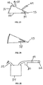
- Fig. 6 is a side sectional view of a portion of a chamber wall, showing engineered structures 40 on the interior surface of the material that faces treatment space 24. Structures 40 are identical in shape and size, and are positioned uniformly apart from one another.
- Fig. 7 is a side sectional view showing engineered structures 41 and 42 intruding into the chamber space, where structures 41 intrude farther than structures 42, and the structures are configured in a regular alternating pattern of 41-42-41-42 and so forth.
- Fig. 6 is
- FIG. 8 is a side sectional view showing engineered structures 43, 44, and 45 intruding into the chamber space, where structures 43 intrude farther than structures 44 and 45, structures 44 intrude less than structures 43 but farther than structures 45, and structures 45 intrude less than structures 43 and 44. These structures are configured in a regular alternating pattern of 43-45-44-45-43-45-44-45-43 and so forth.
- the embodiment shown in Fig. 8 makes it difficult for soft wound tissue to penetrate all of the spaces among the raised structures. A sufficient amount of continuous space is established to make possible the distribution of negative pressure, as well as the addition of fluids and therapies and the removal of fluids and materials from the wound.
- Fig. 8 is a side sectional view showing engineered structures 43, 44, and 45 intruding into the chamber space, where structures 43 intrude farther than structures 44 and 45, structures 44 intrude less than structures 43 but farther than structures 45, and structures 45 intrude less than structures 43 and 44. These structures are configured in a regular alternating pattern
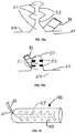
- FIG. 9a is an overview of a portion of the chamber wall, showing engineered structures 47 in the form of raised ridges.
- the engineered structures 47 may be rounded ( Fig. 9b ), square ( Fig. 9c ), or a combination thereof when viewed from the side.
- Fig. 10 is an overview showing engineered dome structures 48 interspersed with ridge structures 47.
- the engineered dome structures 48 are preferably semi-spherical when viewed from the side, although other shapes are contemplated.
- Fig. 11 is an overview of a portion of the chamber wall, showing structures 47 arranged in two parallel lines to form channel 49.
- Fig. 12 shows a channel 49 formed by two parallel lines of raised domed structures 48.
- Such channels can be configured in various patterns, such as radial, circular, concentric, or branching.
- Figs. 13-16 show overviews of patterns of channels 49 leading from tube 32 along the interior surface of chamber 22 facing treatment space 24. For each pattern, the channel 49 defines a space that opens directly to the treatment space 24. The space preferably opens to the treatment space 24 over the entire length of the channel 49.
- Fig. 17 shows a channel 50 formed in a fold of the chamber wall.
- the channel 50 defines a space that opens directly to the treatment space 24.
- the space preferably opens to the treatment space 24 over the entire length of the channel 50.
- the walls of the fold can be configured with structures that prevent the collapse of such space, and ensure continuous open space for the distribution and maintenance of negative pressure, and the passage of liquid, gas, and other material.
- FIG. 18a shows engineered structures 52 that prevent the total collapse of the fold, and ensure continuous channel space 51. All channel spaces created on the interior surface of the chamber wall or by means of folds function as means to increase the effectiveness of distributing and maintaining negative pressure within the chamber, and also as means to enhance the effectiveness of removing gas, liquid, wound fluid, debris, and other materials from the chamber treatment space.
- Fig. 18b shows an embodiment similar to the embodiment shown in Fig. 17 with the addition of engineered raised structures 52 on opposite sides of the fold.
- the engineered structures 52 are provided so that the fold will not collapse to the point where all of its interior surfaces form a tight seal against the movement of negative pressure. However, some of the interior surfaces, such as those adjacent to the fold, preferably contact the wound to provide stimulation as discussed above.
- the folds described in the previous embodiments are preferably formed at certain defined areas by molding or embossing the surfaces of the chamber 22.
- Fig. 19 shows a wound chamber device 120 for delivering negative pressure and therapeutic substances in the form of a tube that can be placed over a limb.
- the wound chamber device 120 is generally cylindrical and includes an open end and a closed end. The open end is preferably sealed with a cuff or collar (not shown), and the open end may include adhesive on the interior surface.
- the wound chamber device 120 includes engineered structures 40 and channels 49 on the interior surface of the chamber wall.
- the wound chamber device 120 may also include folds and channels as described above.
- a fluid collector 60 may be positioned on the tube 32 between the chamber 22 and the suction device 34.
- the collector 60 is intended to receive fluid extracted from the chamber space 24 and debris or material from the wound and store such materials for eventual disposal.
- the collector 60 may be detachable from the tube 32, in order to replace a full collector with an empty collector.
- Suction for the wound treatment device is provided by a suction device 34, which may be a pump that is connected and disconnected to the chamber device by appropriate connectors.
- a suction device 34 may be a pump that is connected and disconnected to the chamber device by appropriate connectors.
- the hand-powered device may be a squeeze bulb that provides suction by means of the energy stored in the material of its construction.
- the suction device may be powered by springs that are compressed by the user. The springs can be selected to produce the clinically desired level of negative pressure. The amount of suction provided by these suction devices is therefore dependent on the level of force generated by squeezed material or the springs.
- the hand powered device preferably cannot produce a high level of suction that may cause an adverse effect to wound healing.
- a suction device 61 in the form of a bulb constructed of a deformable material that stores the energy of deformation may be used.
- the tube 32 communicates with the interior of the suction device 61.
- a one-way exhaust valve 62 also communicates with the interior of the suction device 61.
- air within the device is expelled through the exhaust valve 62.
- a portion of the energy used to deform the suction device 61 is stored in the material of which it is constructed, thus maintaining suction within the device, as well as within the tube 32 and the chamber space 24.
- the bulb is selected and engineered to maintain a constant force and to maintain the clinically desired level of negative pressure within chamber space 24.
- Fluid from the wound 30 can flow through the tube 32 into the suction device 61 where it can be stored prior to disposal. Once the suction device is full of fluid, the production of negative pressure ceases.
- the fluid capacity of the suction device thus operates as a safety shut-off mechanism without the need for electronic sensors and controls.
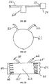
- Fig. 22 shows an alternative suction device 63, consisting of flexible sides 64 and rigid sides 65.
- Compression springs 66 are located within suction device 63.
- the tube 32 and the exhaust valve 62 both communicate with the interior of the suction device 63.
- the springs 66 are compressed and air within the device is expelled through a one-way exhaust valve 62 thus maintaining suction within the device, as well as within the tube 32 and the chamber space 24.
- the springs 66 are selected and engineered to maintain a constant force against rigid sides 65, and to maintain the clinically desired level of negative pressure within chamber space 24. Fluid from the wound 30 can flow through the tube 32 into the suction device 63 where it can be stored prior to disposal of the entire device 63. This suction device will also cease operating when it is filled with fluid.
- Fig. 23 shows an alternative suction device 70, consisting of rigid sides 72, joined by hinge 73, and flexible side 71.
- a torsional spring 74 is attached to either the interior or the exterior of rigid sides 72.
- the tube 32 and the exhaust valve 62 both communicate with the interior of the suction device 70.
- the spring 74 is selected and made to maintain a force against rigid sides 72 to maintain the clinically desired level of negative pressure within chamber space 24. Fluid from the wound 30 can flow through the tube 32 into the suction device 70 where it can be stored prior to disposal of the entire device.
- Fig. 24 shows the device of Fig. 27 where the torsional spring 74 has been replaced by a flat spring 78.
- fluid may flow from the wound to the suction device, where it may be collected and stored for eventual disposal.
- a separate fluid collector such as the fluid collector 60 in Fig. 20 , can be positioned between the chamber and the suction device. Once the suction device has expanded to its original shape, suction ceases. The suction device will not continue to operate, and can be disconnected and disposed of. If treatment is to be continued, a new suction device can be connected and activated.
- Fig. 25 is a sectional view of a trap 80 and a filter 82 interposed between the suction device 34 and the exhaust valve 62 for the purpose of preventing the expulsion of liquids or aerosols from the suction device.
- the present invention can be engineered to operate at vanous levels of negative pressure, in accordance with clinical procedures.
- the commonly accepted range of negative pressure is between 3,400 and 13,800 Pa (.5 and 2 psi).
- the device of the present invention operates efficiently in this range.
- the chamber material conforms to the shape of the wound, and the engineered structures maintain their shape and functionality.
- the chamber can be engineered to operate at higher levels of negative pressure.
- the operating pressure of the device may be higher than the commonly accepted range; that is, the device may operate at a pressure close to 0 Pa (0 psi) before suction ceases.
- the present invention preferably provides continuous negative pressure, but in practice there may be periods of time when negative pressure is not being produced.
- a care giver could provide a program of intermittent negative pressure by manually turning on and off the negative pressure system.
- the source of negative pressure may be controlled to produce intermittent negative pressure.
- the motor may include a controller that is programmed to intermittently provide negative pressure.
- a wound was created in a sample of animal cadaver tissue.
- a pressure sensor was installed in the tissue at the center of the wound.
- a wound chamber device with raised engineered structures on the interior chamber wall was sealed to the skin around the wound.
- a tube from the chamber device was connected to a source of suction capable of delivering a range of negative pressure. The amount of negative pressure measured at the suction source was compared to the measurement at the center of the wound, in order to determine the effectiveness of the device with respect to the distribution of negative pressure to the wound.
- a patient with a full-thickness skin wound was treated with a wound chamber negative pressure device connected to a hand-powered suction pump.
- the interior surface of the chamber contained embossed raised structures.
- the area around the wound was treated with normal skin disinfectants.
- the backing from the adhesive base of the chamber was removed, and the chamber was sealed to the normal skin around the wound.
- the tube was connected to a modified squeeze bulb with an inlet port for fluid, and an exhaust port through which air can be expelled from the bulb.
- a negative pressure of 13,800 Pa (2 psi) was established and maintained within the chamber. After the first 24 hours of treatment, the squeeze bulb had expanded to approximately half of its normal size.
- the bulb was compressed again to its fully flattened configuration.
- the bulb remained in such configuration for an additional 12 hours, at which point the chamber was removed.
- the wound showed healthy granulation tissue and progressed to heal rapidly and with minimal scarring.
- the device produced no adverse effects on the wound or the surrounding skin.
- the device of the present invention is preferably simplified and lightweight.
- the patient is not restricted to a source of electricity or a battery pack.
- the system can be worn with ease, so that the patient's mobility is not otherwise compromised.
- the wound interface appliance can be applied quickly without the need for custom fitting and construction.
- the device preferably does not leak due to the smooth adhesive base, eliminating the need for constant suction from an electric pump with sophisticated controls and safety measure.
- the inner surfaces of the chamber are generally non-porous and nonadherent to prevent any interaction with the wound tissue.
- the suction pump preferably has built-in safety limitations on force of suction, duration of operation, and overfilling of the collector for wound fluid.
Landscapes
- Health & Medical Sciences (AREA)
- Heart & Thoracic Surgery (AREA)
- General Health & Medical Sciences (AREA)
- Engineering & Computer Science (AREA)
- Biomedical Technology (AREA)
- Life Sciences & Earth Sciences (AREA)
- Animal Behavior & Ethology (AREA)
- Vascular Medicine (AREA)
- Public Health (AREA)
- Veterinary Medicine (AREA)
- Anesthesiology (AREA)
- Hematology (AREA)
- Surgical Instruments (AREA)
- Media Introduction/Drainage Providing Device (AREA)
- Massaging Devices (AREA)
Description
- This application claims the benefit of
U. S. Provisional Patent Application No. 60/931,599 filed May 24,2007 - The invention relates generally to the field of wound treatment, and more particularly, to a device for treating wounds with negative pressure and/or therapeutic modalities.
- Many wounds can be treated by the application of negative pressure. The method of such treatment has been practiced for many years. The benefits of such treatment can include: reduction of edema; reduction of wound exudate; reduction of wound size; and stimulation of formation of granulation tissue. Existing devices and appliances for the provision of negative pressure wound therapy are complex. Such devices typically encompass a porous insert such as foam or gauze that is placed into the wound; a tube connecting the insert to a source of suction;
a flexible cover draped over these components and sealed to the skin around the wound; an electrically powered suction pump; controls to operate the pump and monitor the system; containers to collect wound fluids; filters to process the materials removed from the wound; and safety systems to prevent harm to the patient and to block the escape of biological materials into the outside environment. These devices are expensive, labor intensive, and restrictive of patient mobility. The many components, particularly the seals around the insert and the tube, tend to leak. Therefore, suction must be applied either continuously or frequently. - Continuous suction is typically achieved by a vacuum pump powered by an electric motor. These systems require complex means to measure, monitor, and control the operation of the pump in order to ensure the safety of the patient. In addition, many negative pressure devices are contraindicated in the presence of necrotic tissue, invasive infection, active bleeding, and exposed blood vessels. They require the use of a porous insert (i.e., a sponge, foam, gauze, mesh, etc.) in the wound. The insert may present two problems: growth of tissue into the insert, and the harboring of infectious and/or undesirable materials in the insert. Wound tissue can grow into and around such inserts, causing adverse results to the healing process. Moreover, such inserts can retain wound fluid and microorganisms, and can therefore become contaminated and/or infected, presenting an adverse effect to the healing process. In addition, the high cost of these devices may deter or delay their use on patients.
- Existing negative pressure treatment devices are labor intensive since they require the user to assemble, fit and customize a number of components. First, the user must prepare, trim, and size a porous insert of foam, gauze, mesh, or other material that will be placed in the wound. Next, the user must position a tube in the insert, and then cover the tube and insert with a material that is intended to create a leakproof seal. In practice, and as mentioned above, such compositions tend to leak, requiring the frequent application of suction in order to establish and re-establish negative pressure within the space about the wound. In addition, currently available negative pressure devices and systems block the view of the wound, making monitoring and diagnosis more difficult. Therefore, an improved device for applying negative pressure to wounds is needed.
-
WO 2007/002835 A2 discloses a wound dressing. - According to the present invention, there is provided a device for wound treatment as defined in the independent claim.
- In some embodiments, the plurality of structures and the chamber are part of a single ply of material. In addition, in some embodiments, each of the structures in the plurality of structures is semi-rigid.
- In some embodiments, the device includes a wedge-shaped manual pump, and the treatment space is in fluid communication with the wedge-shaped manual pump. The wedge-shaped manual pump may include a spring that biases the wedge-shaped manual pump to an uncompressed position.
- The foregoing and other aims and advantages of the invention will appear in the detailed description that follows. In the description, reference is made to the accompanying drawings that illustrate a preferred embodiment of the invention.
- The invention may be understood by reference to the following description taken in conjunction with the accompanying figures, in which like reference numerals identify like elements. It should be understood that figures represent an example of the present invention and components are not necessarily shown to be proportional to one another. The terms "chamber wall" or "wall" mean any part of the chamber device that forms or encloses the chamber treatment space. The term "overview" means a view from the inside of the chamber treatment space looking toward the interior surface of the chamber wall.
-
Fig. 1 is a perspective view of a wound chamber treatment device with a tube leading from a chamber to a suction source; -
Fig. 2 is a side sectional view of the device inFig. 1 ; -
Fig. 3 is a sectional view of the device inFig. 1 with an additional tube leading to a port; -
Fig. 4 is a sectional view of the device inFig. 1 with a branching tube leading to a port; -
Fig. 5 is a perspective view of the end of the tube communicating with the interior chamber space; -
Fig. 6 is a side sectional view of structures engineered on and into the interior surface of the chamber wall, where the structures are of uniform size and shape, and are spaced uniformly apart; -
Fig. 7 is a side sectional view of two groups of structures engineered on and into the interior surface of the chamber wall, where one group intrudes into the chamber space, the other group intrudes to a lesser extent, and structures from these groups alternate in a regular pattern; -
Fig. 8 is a side sectional view of three groups of structures engineered on and into the interior surface of the chamber wall, where such groups have varying degrees of intrusion into the chamber space and alternate in a regular pattern; -
Fig. 9a is an overview of structures engineered on and into the interior surface of the chamber wall, where the structures consist of raised ridges; -
Fig. 9b is a side sectional view of the raised ridges ofFig. 9 with rounded edges; -
Fig. 9c is a side sectional view of the raised ridges ofFig. 9a with square cross sections; -
Fig. 10 is an overview of the raised ridge structures shown inFig. 9 , with the addition of raised dome structures positioned among the ridges; -
Fig. 11 is an overview of raised ridge structures engineered on and into the interior surface of the chamber wall, where two parallel lines of such structures form a channel; -
Fig. 12 is an overview of raised dome structures engineered on and into the interior surface of the chamber wall, where two parallel lines of such structures form a channel; -
Fig. 13 is a view of a wound chamber, showing a pattern of channels leading to the center of the chamber and then to the tube communicating from the interior of the chamber space; -
Fig. 14 is a view of a radiating pattern of channels leading to the communicating tube; -
Fig. 15 is a view of a branching pattern of channels leading to the communicating tube; -
Fig. 16 is a view of a sub-branching pattern of channels leading to the communicating tube; -
Fig. 17 is a side sectional view of a fold in the chamber wall; -
Fig. 18a is a side sectional view of a fold in the chamber wall, with structures engineered on and into the inner surface of the fold, which structures maintain continuous open space within the fold; -
Fig. 18b is a side sectional view of the fold in the chamber wall ofFig. 17 with structures engineered on the inner surface of the fold; -
Fig. 19 is a view of a wound chamber configured as a tube for placement over a limb, and having engineered structures and channels on the interior surface of the chamber wall; -
Fig. 20 is a sectional view of the device inFig. 1 showing a fluid collector placed before the suction source; -
Fig. 21 is a sectional view of a suction device in the form of a squeeze bulb of deformable material; -
Fig. 22 is a sectional view of a suction device in the form of a flexible chamber containing one or more compression springs; -
Fig. 23 is a sectional view of a suction device in the form of a wedge-shaped chamber containing one or more torsional springs; -
Fig. 24 is a sectional view of the device inFig. 23 containing a flat spring; and -
Fig. 25 is a sectional view of a suction device with a trap and filter incorporated into the exhaust port. - While the invention is susceptible to various modifications and alternative forms, specific embodiments thereof have been shown by way of example in the drawings and are herein described in detail. It should be understood, however, that the description herein of specific embodiments is not intended to limit the invention to the particular forms disclosed, but on the contrary, the intention is to cover all modifications, equivalents, and alternatives falling within the scope of the invention as defined by the appended claims.
- While the present invention may be embodied in any of several different forms, the present invention is described here with the understanding that the present disclosure is to be considered as setting forth an exemplification of the present invention that is not intended to limit the invention to the specific embodiment(s) illustrated.
- The present invention is directed to providing a simple, safe, disposable, and cost-effective device that is easy to install and operate, that allows freedom of motion to the patient, and that overcomes, or at least reduces the effects of, one or more of the problems set forth above. The present invention does not require the use of a porous insert. The one-piece construction of the device eliminates virtually all leaks, therefore preserving and maintaining negative pressure within the wound without the need for constant or frequent regeneration of negative pressure. In addition, the structure of the device is configured to promote wound healing and to create pathways through which negative pressure can be distributed and maintained in the treatment space. The indications for the present invention may be expanded beyond the limitations imposed on current devices. The cost-effectiveness of the present invention may lead to the provision of negative pressure wound therapy on a more widespread basis and earlier in the timeline of wound care.
- One aspect of the present invention is seen in a wound treatment device including a chamber defining a treatment space around the wound. The flexible adhesive base of the chamber forms a water-tight and gas-tight seal. A tube communicates from the treatment space to a source of suction. The suction source also serves as a receptacle for materials removed from the chamber. All components preferably are inexpensive, lightweight, and disposable.
- Referring first to
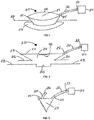
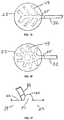
Figs. 1 and 2 , views of awound treatment device 20 are provided. Thedevice 20 includes achamber 22 defining atreatment space 24 and a base 26 that may be sealed to askin surface 28 of a patient over awound 30. In the illustrated embodiment, thechamber 22 has a bellows configuration with afold 23. However, the invention is not so limited, and other configurations of a chamber formed of a flexible, moisture and gas impermeable material may be used. Materials from which thedevice 20 may be made will be discussed in further detail below. Thedevice 20 can be designed for use with any wound or body part, using circular, square, rectangular, tubular, pouch, envelope or other shapes. For example, a chamber in the form of a tube or sleeve for placement over a limb is shown inFig. 19 . Referring again toFigs. 1 and 2 , a dermal or cutaneous adhesive material may be provided on a bottom surface of thebase 26 for providing a fluid-tight seal with sufficient adhesive strength to prevent inadvertent removal of thechamber 22 or breach of the fluid-tight seal during normal patient movement. Numerous adhesive materials sufficient for these purposes are known to those of ordinary skill in the art. - A
tube 32 is attached to thechamber 22 preferably at a location spaced above thebase 26 and communicates with thetreatment space 24. Thetube 32 is constructed to maintain its shape without collapsing and to permit the passage of wound fluids and wound debris. Thetube 32 may be permanently fixed to thechamber 22, or a fitting 25 may be provided to allow the attachment and removal of thetube 32 or any other device that can deliver material or therapies to, or remove material from, thetreatment space 24. Thetube 32 may terminate at a wall of thechamber 22, or it may extend through the wall a distance and terminate within thetreatment space 24, where it may communicate with such space, with channels formed on the inner surface of the chamber wall, or with folds formed in the chamber wall. As another alternative, thetube 32 may connect to thechamber 22 with a Luer fitting. Thetube 32 is sealed to thechamber 22 in such a manner as to prevent the escape of liquid or gas from thetreatment space 24 to the outside environment. A distal end of thetube 32 terminates at asuction device 34. Thesuction device 34 may be a pump, although other types of devices may be used as discussed below. A fitting 33 may be provided to permit the detachment and reattachment of asuction device 34 to thetube 32. - Turning to
Fig. 3 , a sectional view of thedevice 20 is provided, showing a second tube 35 attached to thechamber 22 and communicating with thetreatment space 24, with channels, or with folds. A distal end of the tube 35 terminates in a portal 36. The invention is not limited to any number of communicating tubes, and multiple tubes and portals may be provided for accessing thetreatment space 24.Fig. 4 shows the device inFig. 1 with a branch of thetube 32 that leads to a portal 36. The portal 36 may be used for the delivery of therapeutic modalities -- such as antimicrobials, antibiotics, antifungals, and analgesics -- prior to, during, or after the delivery of negative pressure. As such, the portal 36 may be a Luer fitting configured for attachment to a container or a syringe. Alternatively, therapeutic modalities may be delivered through thesame tube 32 that communicates with thesuction device 34. - Turning now to
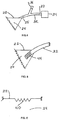
Fig. 5 , the end of thetube 32 extending into thechamber space 24 is shown withmultiple apertures 44. The purpose of theapertures 44 is to ensure that gases, liquids, wound fluid, debris, and other materials can flow and move out of thechamber space 24 into thetube 32 without impediment. - Referring to
Fig. 6 , the interior surfaces of the chamber wall may be configured withstructures 40 that are engineered on the surfaces. The portions of the interior surfaces with engineeredstructures 40 may be varied from that shown in the figures, and preferably a high percentage of the interior surfaces include engineeredstructures 40. The structures preferably cover at least 50% of the interior surfaces, and more preferably at least 95% of the interior surfaces. These structures are raised when viewed from within thechamber space 24, and they intrude into such space in directions generally perpendicular to the interior surfaces of thechamber space 24. These structures can be any shape, including without limitation a cone, a pyramid, a pentagon, a hexagon, a half sphere, a dome, a rod, an elongated ridge with rounded sides, or an elongated ridge with square sides. The structures can be provided as identical shapes, or in any combination of shapes. The structures can be provided with identical sizes, or in any combination of different sizes. The structures may be uniformly or non-uniformly spaced from each other. In addition, the structures may be separated by a portion of the surface of thechamber 22. The distance of intrusion into thechamber treatment space 24 from the chamber wall by such structures is preferably between .01mm and 20mm, and is more preferably between 1mm and 1 cm. The spacing between such structures is preferably between .01mm and 5cm. - The
engineered structures 40 interface with the wound surface during use of thedevice 20. One purpose of these structures is to ensure that negative pressure established within thechamber space 24 is evenly distributed and maintained throughout such space. As negative pressure is established within the tube that leads to the source of suction, the chamber will lie tighter against the wound tissue. Thedevice 20 includes the engineered surfaces 40 in order to define pathways to establish, distribute, and maintain negative pressure across the wound surface and prevent complete contact between the inner surfaces of the chamber and the wound tissue. Without such structures, the chamber wall would make complete contact with the wound surface. As a result, there would be no space within which negative pressure could be established, distributed, and maintained. Therefore, the engineered structures are preferably semi-rigid. The term "semi-rigid" should be understood as meaning that deformation only occurs at a microscopic level under operating negative pressures in the range of 3,400-13,800 Pa (0.5-2 psi). Alternatively, the engineered structures may be somewhat flexible depending on the spacing between the structures. In addition, the structures are engineered to reduce the extent to which wound tissue can enter the space between the structures, so that a sufficient amount of open space is maintained. - An additional purpose of these structures is to serve as a form of stimulation to the wound to produce beneficial results, including without limitation the formation of granulation tissue and an increase of micromechanical forces. Such mechanical forces provide stimulation to a portion of the wound tissue, which has been suggested as a contributing factor to the effectiveness of negative pressure wound therapy. From the above discussion and the figures, it should be understood that the flexible chamber is movable over a range of positions. The range of positions includes a first position, such as the position shown in
Figs. 1 and 2 , in which the engineeredstructures 40 are spaced apart from the opening of the chamber defined by thebase 26. The range of positions also includes a second position in which at least some of the engineeredstructures 40 are positioned in the opening of the chamber. The second position is preferably a position in which the engineeredstructures 40 engage the wound. - The chamber wall can be formed of any appropriate medical grade material that has the following characteristics: flexibility, conformability, gas impermeability, liquid impermeability, the ability to be formed, tooled, and engineered, and the ability to retain the shape, function, and effectiveness of raised engineered structures under desired ranges of negative pressure. In addition, the material is preferably hypo-allergenic and provided to a medical facility in a sterile condition. For example, the chamber device may be made of a flexible, conformable material such as polyurethane, although other similar materials may also be used. The chamber is preferably designed to provide sufficient material to lie against the surface of the wound tissue without special sizing, trimming, or other customizing operations. The chamber may be made from a single ply of material, or may be constructed of multiple layers of material in and on which the structures are engineered. It should be understood that a single ply chamber may be made of multiple sheets of material during manufacturing, but is provided to a medical facility in a state in which the multiple sheets are bonded or otherwise connected to one another. For example, individual three dimensional shapes may be adhered or bonded to the inner surface of the chamber wall during manufacturing to provide the engineered structures. A single ply chamber could also be formed from a single sheet of material that defines both the chamber walls and the engineered structures. Alternatively, a multiple layer chamber is provided to a medical facility in a state in which layers of material are stacked to form the chamber. For example, the layer facing the interior treatment space of the chamber could be a layer containing engineered structures that is bonded onto a generally flat layer of material (or multiple sheets of generally flat layers) by a medical practitioner.
- Engineered structures can be made by techniques familiar to those in the art, such as embossing, stamping, molding, forming, or bonding. According to the present invention, the structures are created by embossing their shape into the material. The embossed structures are left in a concave state relative to the outside of the chamber as shown in
Fig. 6 . Embossed structures may also be formed on a single ply of material that also forms the walls of the chamber and the base. This may provide a chamber that is relatively flexible and semi-rigid structures on a single ply of material. According to an example useful for an understanding of the invention, the cavities may be filled with a suitable material to render the structures solid. As another example useful for understanding of the invention, solid structures can be affixed to the inner surfaces of the chamber. - The raised structures on the inner surfaces of the chamber wall can be configured and distributed in a number of patterns. For example,
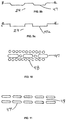
Fig. 6 is a side sectional view of a portion of a chamber wall, showingengineered structures 40 on the interior surface of the material that facestreatment space 24.Structures 40 are identical in shape and size, and are positioned uniformly apart from one another. As another example,Fig. 7 is a side sectional view showing engineered structures 41 and 42 intruding into the chamber space, where structures 41 intrude farther than structures 42, and the structures are configured in a regular alternating pattern of 41-42-41-42 and so forth. As yet another example,Fig. 8 is a side sectional view showingengineered structures structures 43 intrude farther thanstructures 44 and 45,structures 44 intrude less thanstructures 43 but farther than structures 45, and structures 45 intrude less thanstructures Fig. 8 makes it difficult for soft wound tissue to penetrate all of the spaces among the raised structures. A sufficient amount of continuous space is established to make possible the distribution of negative pressure, as well as the addition of fluids and therapies and the removal of fluids and materials from the wound. As yet another example,Fig. 9a is an overview of a portion of the chamber wall, showingengineered structures 47 in the form of raised ridges. Theengineered structures 47 may be rounded (Fig. 9b ), square (Fig. 9c ), or a combination thereof when viewed from the side. As yet another example,Fig. 10 is an overview showing engineereddome structures 48 interspersed withridge structures 47. The engineereddome structures 48 are preferably semi-spherical when viewed from the side, although other shapes are contemplated. - The distribution and maintenance of negative pressure within the chamber device and at all points on the wound may be enhanced by providing defined channel spaces as pathways among the raised engineered structures for the distribution of negative pressure. However, defined channel spaces are not required for providing fluid pathways within the treatment space.
Fig. 11 is an overview of a portion of the chamber wall, showingstructures 47 arranged in two parallel lines to formchannel 49.Fig. 12 shows achannel 49 formed by two parallel lines of raiseddomed structures 48. Such channels can be configured in various patterns, such as radial, circular, concentric, or branching.Figs. 13-16 show overviews of patterns ofchannels 49 leading fromtube 32 along the interior surface ofchamber 22 facingtreatment space 24. For each pattern, thechannel 49 defines a space that opens directly to thetreatment space 24. The space preferably opens to thetreatment space 24 over the entire length of thechannel 49. - The distribution and maintenance of negative pressure with the chamber device and at all points on the wound can also be enhanced by the use of folds in the chamber wall to create additional channel space for the distribution of negative pressure. When negative pressure is established within the chamber, the material will tend to fold along the pre-formed location.
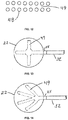
Fig. 17 shows achannel 50 formed in a fold of the chamber wall. Thechannel 50 defines a space that opens directly to thetreatment space 24. The space preferably opens to thetreatment space 24 over the entire length of thechannel 50. In order to increase the amount of channel space within such fold, the walls of the fold can be configured with structures that prevent the collapse of such space, and ensure continuous open space for the distribution and maintenance of negative pressure, and the passage of liquid, gas, and other material. As an alternative,Fig. 18a showsengineered structures 52 that prevent the total collapse of the fold, and ensurecontinuous channel space 51. All channel spaces created on the interior surface of the chamber wall or by means of folds function as means to increase the effectiveness of distributing and maintaining negative pressure within the chamber, and also as means to enhance the effectiveness of removing gas, liquid, wound fluid, debris, and other materials from the chamber treatment space. As another alternative,Fig. 18b shows an embodiment similar to the embodiment shown inFig. 17 with the addition of engineered raisedstructures 52 on opposite sides of the fold. Theengineered structures 52 are provided so that the fold will not collapse to the point where all of its interior surfaces form a tight seal against the movement of negative pressure. However, some of the interior surfaces, such as those adjacent to the fold, preferably contact the wound to provide stimulation as discussed above. The folds described in the previous embodiments are preferably formed at certain defined areas by molding or embossing the surfaces of thechamber 22. -
Fig. 19 shows awound chamber device 120 for delivering negative pressure and therapeutic substances in the form of a tube that can be placed over a limb. Thewound chamber device 120 is generally cylindrical and includes an open end and a closed end. The open end is preferably sealed with a cuff or collar (not shown), and the open end may include adhesive on the interior surface. Thewound chamber device 120 includes engineeredstructures 40 andchannels 49 on the interior surface of the chamber wall. Thewound chamber device 120 may also include folds and channels as described above. - As shown in
Fig. 20 , afluid collector 60 may be positioned on thetube 32 between thechamber 22 and thesuction device 34. Thecollector 60 is intended to receive fluid extracted from thechamber space 24 and debris or material from the wound and store such materials for eventual disposal. Thecollector 60 may be detachable from thetube 32, in order to replace a full collector with an empty collector. - Suction for the wound treatment device is provided by a
suction device 34, which may be a pump that is connected and disconnected to the chamber device by appropriate connectors. Although the wound chamber can be used with a motor driven pump, it is also effective with a hand-powered device actuated by the caregiver or patient. The hand-powered device may be a squeeze bulb that provides suction by means of the energy stored in the material of its construction. Alternatively, the suction device may be powered by springs that are compressed by the user. The springs can be selected to produce the clinically desired level of negative pressure. The amount of suction provided by these suction devices is therefore dependent on the level of force generated by squeezed material or the springs. Unlike a motor driven suction pump, the hand powered device preferably cannot produce a high level of suction that may cause an adverse effect to wound healing. - Referring to
Fig. 21 , asuction device 61 in the form of a bulb constructed of a deformable material that stores the energy of deformation may be used. Thetube 32 communicates with the interior of thesuction device 61. A one-way exhaust valve 62 also communicates with the interior of thesuction device 61. When the user squeezes thesuction device 61, air within the device is expelled through theexhaust valve 62. A portion of the energy used to deform thesuction device 61 is stored in the material of which it is constructed, thus maintaining suction within the device, as well as within thetube 32 and thechamber space 24. The bulb is selected and engineered to maintain a constant force and to maintain the clinically desired level of negative pressure withinchamber space 24. Fluid from thewound 30 can flow through thetube 32 into thesuction device 61 where it can be stored prior to disposal. Once the suction device is full of fluid, the production of negative pressure ceases. The fluid capacity of the suction device thus operates as a safety shut-off mechanism without the need for electronic sensors and controls. -
Fig. 22 shows analternative suction device 63, consisting offlexible sides 64 and rigid sides 65. Compression springs 66 are located withinsuction device 63. Thetube 32 and theexhaust valve 62 both communicate with the interior of thesuction device 63. When the user squeezes the rigid sides 65 towards one another, thesprings 66 are compressed and air within the device is expelled through a one-way exhaust valve 62 thus maintaining suction within the device, as well as within thetube 32 and thechamber space 24. Thesprings 66 are selected and engineered to maintain a constant force against rigid sides 65, and to maintain the clinically desired level of negative pressure withinchamber space 24. Fluid from thewound 30 can flow through thetube 32 into thesuction device 63 where it can be stored prior to disposal of theentire device 63. This suction device will also cease operating when it is filled with fluid. -
Fig. 23 shows an alternative suction device 70, consisting ofrigid sides 72, joined byhinge 73, andflexible side 71. Atorsional spring 74 is attached to either the interior or the exterior ofrigid sides 72. Thetube 32 and theexhaust valve 62 both communicate with the interior of the suction device 70. When the user squeezes therigid sides 72 towards one another, thespring 74 is compressed and air within the device is expelled through a one-way exhaust valve 62, thus maintaining negative pressure within the device, as well as within thetube 32 and thechamber space 24. Thespring 74 is selected and made to maintain a force againstrigid sides 72 to maintain the clinically desired level of negative pressure withinchamber space 24. Fluid from thewound 30 can flow through thetube 32 into the suction device 70 where it can be stored prior to disposal of the entire device.Fig. 24 shows the device of Fig. 27 where thetorsional spring 74 has been replaced by aflat spring 78. - For the previous suction devices, once suction has been established, fluid may flow from the wound to the suction device, where it may be collected and stored for eventual disposal. Alternatively, a separate fluid collector, such as the
fluid collector 60 inFig. 20 , can be positioned between the chamber and the suction device. Once the suction device has expanded to its original shape, suction ceases. The suction device will not continue to operate, and can be disconnected and disposed of. If treatment is to be continued, a new suction device can be connected and activated. -
Fig. 25 is a sectional view of atrap 80 and afilter 82 interposed between thesuction device 34 and theexhaust valve 62 for the purpose of preventing the expulsion of liquids or aerosols from the suction device. - The present invention can be engineered to operate at vanous levels of negative pressure, in accordance with clinical procedures. Historically, the commonly accepted range of negative pressure is between 3,400 and 13,800 Pa (.5 and 2 psi). The device of the present invention operates efficiently in this range. The chamber material conforms to the shape of the wound, and the engineered structures maintain their shape and functionality. However, the chamber can be engineered to operate at higher levels of negative pressure. In addition, if a hand-powered suction device is used, the operating pressure of the device may be higher than the commonly accepted range; that is, the device may operate at a pressure close to 0 Pa (0 psi) before suction ceases.
- The present invention preferably provides continuous negative pressure, but in practice there may be periods of time when negative pressure is not being produced. In addition, a care giver could provide a program of intermittent negative pressure by manually turning on and off the negative pressure system. Alternatively, the source of negative pressure may be controlled to produce intermittent negative pressure. For example, if a motor-driven pump is provided as the source of negative pressure, the motor may include a controller that is programmed to intermittently provide negative pressure.
- The effectiveness of the raised engineered structures in distributing and maintaining negative pressure within the chamber and across the wound surface has been demonstrated in a test model. A wound was created in a sample of animal cadaver tissue. A pressure sensor was installed in the tissue at the center of the wound. A wound chamber device with raised engineered structures on the interior chamber wall was sealed to the skin around the wound. A tube from the chamber device was connected to a source of suction capable of delivering a range of negative pressure. The amount of negative pressure measured at the suction source was compared to the measurement at the center of the wound, in order to determine the effectiveness of the device with respect to the distribution of negative pressure to the wound. The following values were obtained:
Pressure at Source (mmHg) Pressure in Wound (mmHg) -80 -65 (81.25% efficiency) -100 -86 (86.00% efficiency) -120 -100 (83.33% efficiency) - The operation of the device may be illustrated by the following case. A patient with a full-thickness skin wound was treated with a wound chamber negative pressure device connected to a hand-powered suction pump. The interior surface of the chamber contained embossed raised structures. The area around the wound was treated with normal skin disinfectants. The backing from the adhesive base of the chamber was removed, and the chamber was sealed to the normal skin around the wound. The tube was connected to a modified squeeze bulb with an inlet port for fluid, and an exhaust port through which air can be expelled from the bulb. By squeezing the bulb down to its flattest configuration, a negative pressure of 13,800 Pa (2 psi) was established and maintained within the chamber. After the first 24 hours of treatment, the squeeze bulb had expanded to approximately half of its normal size. The bulb was compressed again to its fully flattened configuration. The bulb remained in such configuration for an additional 12 hours, at which point the chamber was removed. The wound showed healthy granulation tissue and progressed to heal rapidly and with minimal scarring. The device produced no adverse effects on the wound or the surrounding skin.
- The present invention eliminates many of the drawbacks to existing negative pressure wound therapy systems. For example, the device of the present invention is preferably simplified and lightweight. In some embodiments of the invention, the patient is not restricted to a source of electricity or a battery pack. The system can be worn with ease, so that the patient's mobility is not otherwise compromised. In addition, the wound interface appliance can be applied quickly without the need for custom fitting and construction. The device preferably does not leak due to the smooth adhesive base, eliminating the need for constant suction from an electric pump with sophisticated controls and safety measure. There is no porous wound insert that can potentially cause tissue in-growth and harbor infectious material. Instead, the inner surfaces of the chamber are generally non-porous and nonadherent to prevent any interaction with the wound tissue. Further still, the suction pump preferably has built-in safety limitations on force of suction, duration of operation, and overfilling of the collector for wound fluid.
- The particular embodiments disclosed above are illustrative only, as the invention may be modified and practiced in different but equivalent manners apparent to those skilled in the art having the benefit of the teachings herein. Furthermore, no limitations are intended to the details of construction or design herein shown, other than as described in the claims below. It is therefore evident that the particular embodiments disclosed above may be altered or modified and all such variations are considered within the scope of the invention as defined in the claims. Accordingly, the protection sought herein is as set forth in the claims below.
Claims (15)
- A device (20) for wound treatment, comprising:a chamber (22) that includes an inner surface and defines a treatment space (24), the chamber (22) being made of a flexible impermeable material;a plurality of embossed structures (40) configured to engage a wound (30) and to exert mechanical stress on the wound (30) and configured to create pathways through which negative pressure can be distributed and maintained in the treatment space (24) and prevent complete contact between the inner surface and the wound (30), the plurality of embossed structures (40) intruding from the inner surface of the chamber (22) into the treatment space (24) and being in a concave state relative to the outside of the chamber (22); anda tube (32, 35) having a first end connected to the chamber (22), the tube (32, 35) being in fluid communication with the treatment space (24) so as to enable at least one selected from the group of applying negative pressure to the treatment space (24) and applying a therapeutic modality.
- The device (20) of claim 1, wherein:the plurality of embossed structures (40) are arranged in a pattern to define a channel on the inner surface of the chamber (22); oreach of the embossed structures (40) in the plurality of embossed structures (40) intrudes into the treatment space (24) in a direction that is generally perpendicular to the inner surface; oreach of the embossed structures (40) has a shape selected from the group of a cone, a pyramid, a pentagon, a hexagon, a half sphere, a dome, a rod, an elongated ridge with rounded sides, and an elongated ridge with square sides.
- The device (20) of claim 1, wherein:the chamber (22) has a bellows configuration; orthe chamber (22) is generally cylindrical and configured to treat a wound (30) on a limb.
- The device (20) of claim 1, wherein the chamber (22) is made from a single ply of material;
wherein optionally the plurality of embossed structures (40) and the chamber (22) are part of a single ply of material. - The device of claim 4, wherein:each of the embossed structures (40) in the plurality of embossed structures (40) is semi-rigid; orthe device (20) further comprises a base (26) that defines a first opening of the chamber (22), and wherein the plurality of embossed structures (40), the chamber (22), and the base (26) are part of a single ply of material.
- The device (20) of any of claims 1 to 4, further comprising a base (26) connected to the chamber (22) and configured to form a seal over the wound (30),
wherein the base (26) includes a first surface having an adhesive, and the base (26) defines a first opening of the chamber (22);
wherein optionally the embossed structures (40) are spaced apart from the first opening defined by the base (26). - The device (20) of claim 6, wherein the tube (32, 35) connects to the chamber (22) at a position spaced apart from the first opening defined by the chamber (22).
- The device (20) of claim 1 , further comprising a suction device (34), a fluid trap (80), and an exhaust port (62), wherein the suction device (34) is in fluid communication with the treatment space (24), the fluid trap (80), and the exhaust port (62), and the fluid trap (80) is fluidly positioned between the suction device (34) and the exhaust port (62).
- The device (20) of claim 1, further comprising a wedge-shaped manual pump, and wherein the treatment space is in fluid communication with the wedge-shaped manual pump;
wherein optionally the wedge-shaped manual pump includes a spring that biases the wedge-shaped manual pump to an uncompressed position. - The device (20) of any preceding claim, wherein:the plurality of embossed structures (40) includes first structures and second structures, the first structures having a first height dimension and the second structures having a second height dimension, and the first height dimension is greater than the second height dimension.
- The device (20) of any preceding claim, wherein:the embossed structures (40) are on the inner surface; and/orthe embossed structures (40) cover at least 95% of the inner surface.
- The device (20) of any preceding claim, wherein the flexible impermeable material is conformable to the shape of the wound (30).
- The device (20) of any preceding claim, wherein
a distal end of the tube (35) terminates in a portal (36). - The device (20) of any preceding claim, wherein the chamber (22) is movable over a range of positions, the range of positions including a first position in which the embossed structures (40) are spaced apart from the opening of the chamber (22) and a second position in which the embossed structures (40) engage the wound (30).
- The device of any preceding claim, wherein:the embossed structures (40) are uniformly spaced from each other; orthe embossed structures (40) are non-uniformly spaced from each other.
Applications Claiming Priority (2)
| Application Number | Priority Date | Filing Date | Title |
|---|---|---|---|
| US93159907P | 2007-05-24 | 2007-05-24 | |
| PCT/US2008/064897 WO2008154158A2 (en) | 2007-05-24 | 2008-05-27 | Woundtreatment device employing negative pressure |
Publications (3)
| Publication Number | Publication Date |
|---|---|
| EP2157948A2 EP2157948A2 (en) | 2010-03-03 |
| EP2157948A4 EP2157948A4 (en) | 2014-01-22 |
| EP2157948B1 true EP2157948B1 (en) | 2017-02-15 |
Family
ID=40130427
Family Applications (1)
| Application Number | Title | Priority Date | Filing Date |
|---|---|---|---|
| EP08756312.8A Active EP2157948B1 (en) | 2007-05-24 | 2008-05-27 | Wound treatment device employing negative pressure |
Country Status (8)
| Country | Link |
|---|---|
| US (6) | US8632523B2 (en) |
| EP (1) | EP2157948B1 (en) |
| JP (2) | JP5642539B2 (en) |
| CN (2) | CN101784244B (en) |
| AU (2) | AU2008262140B2 (en) |
| CA (1) | CA2688167C (en) |
| ES (1) | ES2625463T3 (en) |
| WO (1) | WO2008154158A2 (en) |
Families Citing this family (120)
| Publication number | Priority date | Publication date | Assignee | Title |
|---|---|---|---|---|
| US9820888B2 (en) | 2006-09-26 | 2017-11-21 | Smith & Nephew, Inc. | Wound dressing |
| DE602007004546D1 (en) | 2006-09-28 | 2010-03-18 | Tyco Healthcare | Portable wound therapy system |
| US11511094B2 (en) | 2006-11-21 | 2022-11-29 | Mark R. Moore | Apparatus and method for deploying a surgical preparation |
| EP2157948B1 (en) * | 2007-05-24 | 2017-02-15 | Applied Tissue Technologies Llc | Wound treatment device employing negative pressure |
| BRPI0817544A2 (en) | 2007-10-10 | 2017-05-02 | Univ Wake Forest Health Sciences | apparatus for treating damaged spinal cord tissue |
| GB0723855D0 (en) | 2007-12-06 | 2008-01-16 | Smith & Nephew | Apparatus and method for wound volume measurement |
| GB2455962A (en) | 2007-12-24 | 2009-07-01 | Ethicon Inc | Reinforced adhesive backing sheet, for plaster |
| SG174765A1 (en) | 2008-03-05 | 2011-10-28 | Kci Licensing Inc | Dressing and method for applying reduced pressure to and collecting andstoring fluid from a tissue site |
| US9033942B2 (en) | 2008-03-07 | 2015-05-19 | Smith & Nephew, Inc. | Wound dressing port and associated wound dressing |
| GB0804654D0 (en) | 2008-03-13 | 2008-04-16 | Smith & Nephew | Vacuum closure device |
| EP2977068B1 (en) | 2008-07-11 | 2017-10-11 | KCI Licensing, Inc. | Manually-actuated, reduced-pressure systems for treating wounds |
| ES2633142T3 (en) | 2008-07-18 | 2017-09-19 | Wake Forest University Health Sciences | Apparatus for modulation of cardiac tissue through topical application of vacuum to minimize death and cell damage |
| GB0902368D0 (en) | 2009-02-13 | 2009-04-01 | Smith & Nephew | Wound packing |
| US20100324516A1 (en) | 2009-06-18 | 2010-12-23 | Tyco Healthcare Group Lp | Apparatus for Vacuum Bridging and/or Exudate Collection |
| DE102009031992A1 (en) * | 2009-07-06 | 2011-01-13 | Paul Hartmann Ag | Device for negative pressure therapy of wounds |
| EP2515961B1 (en) | 2009-12-22 | 2019-04-17 | Smith & Nephew, Inc. | Apparatuses for negative pressure wound therapy |
| US9358158B2 (en) | 2010-03-16 | 2016-06-07 | Kci Licensing, Inc. | Patterned neo-epithelialization dressings, systems, and methods |
| US8814842B2 (en) | 2010-03-16 | 2014-08-26 | Kci Licensing, Inc. | Delivery-and-fluid-storage bridges for use with reduced-pressure systems |
| USRE48117E1 (en) | 2010-05-07 | 2020-07-28 | Smith & Nephew, Inc. | Apparatuses and methods for negative pressure wound therapy |
| GB201015656D0 (en) | 2010-09-20 | 2010-10-27 | Smith & Nephew | Pressure control apparatus |
| USD714433S1 (en) | 2010-12-22 | 2014-09-30 | Smith & Nephew, Inc. | Suction adapter |
| US9050398B2 (en) | 2010-12-22 | 2015-06-09 | Smith & Nephew, Inc. | Apparatuses and methods for negative pressure wound therapy |
| GB2488749A (en) | 2011-01-31 | 2012-09-12 | Systagenix Wound Man Ip Co Bv | Laminated silicone coated wound dressing |
| CN106974683B (en) | 2011-02-04 | 2020-02-21 | 马萨诸塞州大学 | Negative pressure wound closure device |
| US9421132B2 (en) | 2011-02-04 | 2016-08-23 | University Of Massachusetts | Negative pressure wound closure device |
| WO2012142473A1 (en) * | 2011-04-15 | 2012-10-18 | University Of Massachusetts | Surgical cavity drainage and closure system |
| GB201106491D0 (en) | 2011-04-15 | 2011-06-01 | Systagenix Wound Man Ip Co Bv | Patterened silicone coating |
| EP2567681B1 (en) * | 2011-09-09 | 2014-11-12 | Paul Hartmann AG | Wound dressing for the abdominal area |
| CA2851495A1 (en) * | 2011-09-30 | 2013-04-04 | Eksigent Technologies, Llc | Electrokinetic pump based wound treatment system and methods |
| US9084845B2 (en) | 2011-11-02 | 2015-07-21 | Smith & Nephew Plc | Reduced pressure therapy apparatuses and methods of using same |
| CN103930188B (en) * | 2011-12-01 | 2016-06-01 | 株式会社东芝 | Carbon dioxide recovery equipment, process for carbon dioxide recovery and amine compound recovery method |
| EP3005997A1 (en) | 2011-12-16 | 2016-04-13 | KCI Licensing, Inc. | Releasable medical drapes |
| US10940047B2 (en) | 2011-12-16 | 2021-03-09 | Kci Licensing, Inc. | Sealing systems and methods employing a hybrid switchable drape |
| WO2013123005A1 (en) * | 2012-02-13 | 2013-08-22 | Integrated Healing Technologies | Wound dressing apparatus |
| WO2013154780A1 (en) | 2012-04-12 | 2013-10-17 | Wake Forest University Health Sciences | Design of a conduit for peripheral nerve replacement |
| CA2874396A1 (en) | 2012-05-22 | 2014-01-23 | Smith & Nephew Plc | Wound closure device |
| WO2013175310A2 (en) | 2012-05-22 | 2013-11-28 | Smith & Nephew Plc | Apparatuses and methods for wound therapy |
| CA2874581C (en) | 2012-05-24 | 2022-06-07 | Smith & Nephew Inc. | Devices and methods for treating and closing wounds with negative pressure |
| AU2013290346B2 (en) | 2012-07-16 | 2018-06-07 | Smith & Nephew, Inc. | Negative pressure wound closure device |
| US10219895B2 (en) | 2012-10-26 | 2019-03-05 | Wake Forest University Health Sciences | Nanofiber-based graft for heart valve replacement and methods of using the same |
| KR20150085837A (en) | 2012-11-16 | 2015-07-24 | 케이씨아이 라이센싱 인코포레이티드 | Medical drafe with pattern adhesive layers and method of manufacturing same |
| GB201222770D0 (en) | 2012-12-18 | 2013-01-30 | Systagenix Wound Man Ip Co Bv | Wound dressing with adhesive margin |
| US10245011B2 (en) * | 2012-12-25 | 2019-04-02 | Osaka University | Hemostatic agent applicator |
| US20140207027A1 (en) * | 2013-01-24 | 2014-07-24 | The Cleveland Clinic Foundation | Wound cover apparatus and method |
| EP2968016B1 (en) | 2013-03-13 | 2018-07-11 | Smith&Nephew, Inc. | Negative pressure wound closure device and systems and methods of use in treating wounds with negative pressure |
| US10159771B2 (en) | 2013-03-14 | 2018-12-25 | Smith & Nephew Plc | Compressible wound fillers and systems and methods of use in treating wounds with negative pressure |
| EP3238674B1 (en) | 2013-03-14 | 2019-01-30 | KCI Licensing, Inc. | Absorbent dressing with hybrid drape |
| US20160030722A1 (en) * | 2013-03-15 | 2016-02-04 | The General Hospital Corporation | Method and apparatus for wound dressing |
| AU2014291873B2 (en) | 2013-07-16 | 2019-01-24 | Smith & Nephew Plc | Apparatus for wound therapy |
| WO2015030963A1 (en) | 2013-08-26 | 2015-03-05 | Kci Licensing, Inc. | Dressing interface with moisture controlling feature and sealing function |
| JP6723917B2 (en) | 2013-10-21 | 2020-07-15 | スミス アンド ネフュー インコーポレイテッド | Negative pressure wound closure device |
| EP3062753B1 (en) | 2013-10-28 | 2018-11-21 | KCI Licensing, Inc. | Hybrid sealing tape |
| US9956120B2 (en) | 2013-10-30 | 2018-05-01 | Kci Licensing, Inc. | Dressing with sealing and retention interface |
| EP3513773A1 (en) | 2013-10-30 | 2019-07-24 | KCI Licensing, Inc. | Condensate absorbing and dissipating system |
| AU2014342903B2 (en) | 2013-10-30 | 2018-09-20 | Solventum Intellectual Properties Company | Dressing with differentially sized perforations |
| US9925092B2 (en) | 2013-10-30 | 2018-03-27 | Kci Licensing, Inc. | Absorbent conduit and system |
| US10179073B2 (en) | 2014-01-21 | 2019-01-15 | Smith & Nephew Plc | Wound treatment apparatuses |
| JP6742908B2 (en) | 2014-01-21 | 2020-08-19 | スミス アンド ネフュー ピーエルシーSmith & Nephew Public Limited Company | Crushable negative pressure wound dressing |
| EP3848009A1 (en) | 2014-02-28 | 2021-07-14 | 3M Innovative Properties Company | Hybrid drape having a gel-coated perforated mesh |
| US11026844B2 (en) | 2014-03-03 | 2021-06-08 | Kci Licensing, Inc. | Low profile flexible pressure transmission conduit |
| US10531977B2 (en) | 2014-04-17 | 2020-01-14 | Coloplast A/S | Thermoresponsive skin barrier appliances |
| US10406266B2 (en) | 2014-05-02 | 2019-09-10 | Kci Licensing, Inc. | Fluid storage devices, systems, and methods |
| EP3854361B8 (en) | 2014-06-05 | 2024-03-27 | Solventum Intellectual Properties Company | Dressing with fluid acquisition and distribution characteristics |
| WO2016100098A1 (en) | 2014-12-17 | 2016-06-23 | Kci Licensing, Inc. | Dressing with offloading capability |
| EP3288509B1 (en) | 2015-04-29 | 2022-06-29 | Smith & Nephew, Inc | Negative pressure wound closure device |
| WO2016182977A1 (en) | 2015-05-08 | 2016-11-17 | Kci Licensing, Inc. | Low acuity dressing with integral pump |
| EP3741335B1 (en) | 2015-09-01 | 2023-05-24 | KCI Licensing, Inc. | Dressing with increased apposition force |
| EP3349807B1 (en) | 2015-09-17 | 2021-02-24 | 3M Innovative Properties Company | Hybrid silicone and acrylic adhesive cover for use with wound treatment |
| US10814049B2 (en) | 2015-12-15 | 2020-10-27 | University Of Massachusetts | Negative pressure wound closure devices and methods |
| US10575991B2 (en) | 2015-12-15 | 2020-03-03 | University Of Massachusetts | Negative pressure wound closure devices and methods |
| US11471586B2 (en) | 2015-12-15 | 2022-10-18 | University Of Massachusetts | Negative pressure wound closure devices and methods |
| CN108472160B (en) | 2015-12-30 | 2022-02-22 | 史密夫及内修公开有限公司 | Negative pressure wound therapy apparatus |
| ES2882336T3 (en) | 2016-07-08 | 2021-12-01 | Convatec Technologies Inc | Flexible negative pressure system |
| US11135351B2 (en) | 2016-08-30 | 2021-10-05 | Smith & Nephew Plc | Systems and methods for applying reduced pressure therapy |
| WO2018056060A1 (en) * | 2016-09-23 | 2018-03-29 | 株式会社村田製作所 | Negative pressure wound therapy instrument |
| EP3518847B1 (en) | 2016-09-27 | 2023-03-01 | Smith & Nephew plc | Wound closure devices with dissolvable portions |
| WO2018085457A1 (en) | 2016-11-02 | 2018-05-11 | Smith & Nephew Inc. | Wound closure devices |
| JP2020513909A (en) * | 2016-12-22 | 2020-05-21 | アプライド ティシュ テクノロジーズ エルエルシーApplied Tissue Technologies Llc | Devices and methods for wound healing |
| JP7231227B2 (en) | 2017-02-22 | 2023-03-01 | コーネル ユニヴァーシティー | Mechanical vacuum dressing for mechanical management, protection and aspiration of small incisions |
| JP2020523116A (en) * | 2017-06-12 | 2020-08-06 | ケーシーアイ ライセンシング インコーポレイテッド | Cloth wound filler |
| US11324876B2 (en) | 2017-06-13 | 2022-05-10 | Smith & Nephew Plc | Collapsible structure and method of use |
| AU2018285236B2 (en) | 2017-06-13 | 2024-02-29 | Smith & Nephew Plc | Wound closure device and method of use |
| US11583623B2 (en) | 2017-06-14 | 2023-02-21 | Smith & Nephew Plc | Collapsible structure for wound closure and method of use |
| EP3638173A1 (en) | 2017-06-14 | 2020-04-22 | Smith & Nephew, Inc | Control of wound closure and fluid removal management in wound therapy |
| JP2020523052A (en) | 2017-06-14 | 2020-08-06 | スミス アンド ネフュー インコーポレイテッド | Fluid removal management and control of wound closure in wound care |
| JP7419072B2 (en) | 2017-06-14 | 2024-01-22 | スミス アンド ネフュー ピーエルシー | Foldable sheet for wound closure and method of use |
| EP3658090B1 (en) | 2017-07-27 | 2021-11-10 | Smith & Nephew PLC | Customizable wound closure device |
| EP3664756B1 (en) | 2017-08-07 | 2024-01-24 | Smith & Nephew plc | Wound closure device with protective layer |
| WO2019042790A1 (en) | 2017-08-29 | 2019-03-07 | Smith & Nephew Plc | Systems and methods for monitoring wound closure |
| CN111432855B (en) | 2017-12-06 | 2024-02-23 | 康奈尔大学 | Manually operated Negative Pressure Wound Therapy (NPWT) bandages with improved pump efficiency, automatic pressure indicator and automatic pressure limiter |
| US11559423B2 (en) | 2017-12-22 | 2023-01-24 | Coloplast A/S | Medical appliance system, monitor device, and method of monitoring a medical appliance |
| US11622719B2 (en) | 2017-12-22 | 2023-04-11 | Coloplast A/S | Sensor assembly part, base plate and monitor device of a medical system and associated method |
| EP3727236A1 (en) | 2017-12-22 | 2020-10-28 | Coloplast A/S | Sensor assembly part and a base plate for an ostomy appliance and a method for manufacturing a sensor assembly part and a base plate |
| US11607334B2 (en) | 2017-12-22 | 2023-03-21 | Coloplast A/S | Base plate for a medical appliance, a monitor device and a system for a medical appliance |
| US11654043B2 (en) | 2017-12-22 | 2023-05-23 | Coloplast A/S | Sensor assembly part and a base plate for a medical appliance and a method for manufacturing a base plate or a sensor assembly part |
| US10849781B2 (en) | 2017-12-22 | 2020-12-01 | Coloplast A/S | Base plate for an ostomy appliance |
| AU2018391323B2 (en) | 2017-12-22 | 2024-03-21 | Coloplast A/S | Base plate and sensor assembly of an ostomy system having a leakage sensor |
| WO2019120452A1 (en) * | 2017-12-22 | 2019-06-27 | Coloplast A/S | Coupling part with a hinge for an ostomy base plate and sensor assembly part |
| EP3727242B1 (en) | 2017-12-22 | 2022-03-09 | Coloplast A/S | Monitor device of an ostomy system having a connector for coupling to both a base plate and an accessory device |
| EP3727222B1 (en) | 2017-12-22 | 2024-05-08 | Coloplast A/S | Sensor assembly part for an ostomy appliance and a method for manufacturing a sensor assembly part |
| US10799385B2 (en) | 2017-12-22 | 2020-10-13 | Coloplast A/S | Ostomy appliance with layered base plate |
| US11628084B2 (en) | 2017-12-22 | 2023-04-18 | Coloplast A/S | Sensor assembly part and a base plate for a medical appliance and a device for connecting to a base plate or a sensor assembly part |
| WO2019120439A1 (en) | 2017-12-22 | 2019-06-27 | Coloplast A/S | Calibration methods for ostomy appliance tools |
| LT3727232T (en) | 2017-12-22 | 2022-04-25 | Coloplast A/S | Ostomy appliance with selective sensor points and related methods |
| US11819443B2 (en) | 2017-12-22 | 2023-11-21 | Coloplast A/S | Moisture detecting base plate for a medical appliance and a system for determining moisture propagation in a base plate and/or a sensor assembly part |
| JP2021508269A (en) | 2017-12-22 | 2021-03-04 | コロプラスト アクティーゼルスカブ | A method for manufacturing a base plate for an ostomy orthosis and a sensor assembly part for the base plate, and a base plate and a sensor assembly part. |
| LT3727234T (en) | 2017-12-22 | 2022-04-25 | Coloplast A/S | Ostomy appliance with angular leakage detection |
| US10500084B2 (en) | 2017-12-22 | 2019-12-10 | Coloplast A/S | Accessory devices of an ostomy system, and related methods for communicating leakage state |
| EP3727247B1 (en) | 2017-12-22 | 2022-04-20 | Coloplast A/S | Tools and methods for placing an ostomy appliance on a user |
| US11471318B2 (en) | 2017-12-22 | 2022-10-18 | Coloplast A/S | Data collection schemes for a medical appliance and related methods |
| WO2019161861A1 (en) | 2018-02-20 | 2019-08-29 | Coloplast A/S | Sensor assembly part and a base plate for an ostomy appliance and a device for connecting to a base plate and/or a sensor assembly part |
| GB201811449D0 (en) | 2018-07-12 | 2018-08-29 | Smith & Nephew | Apparatuses and methods for negative pressure wound therapy |
| US11612512B2 (en) | 2019-01-31 | 2023-03-28 | Coloplast A/S | Moisture detecting base plate for an ostomy appliance and a system for determining moisture propagation in a base plate and/or a sensor assembly part |
| WO2020205448A1 (en) * | 2019-03-29 | 2020-10-08 | Kci Licensing, Inc. | Dressing with integrated pump and releasably coupled pump actuator |
| CN110522419B (en) * | 2019-09-03 | 2021-11-02 | 苏州元禾医疗器械有限公司 | Wound repair degree detection device and manufacturing method thereof |
| US11696962B2 (en) | 2019-10-16 | 2023-07-11 | Mark R. Moore | Apparatus and method for deploying a preoperative skin disinfection device with integrated drape |
| EP4087629A4 (en) * | 2020-01-10 | 2024-01-17 | Applied Tissue Tech Llc | Devices and methods for negative pressure therapy |
| US20220008632A1 (en) * | 2020-07-13 | 2022-01-13 | Wellness Allied Inc | Cupping auxiliary consumable, cupping kit, and cupping method |
| US20230030893A1 (en) | 2021-07-29 | 2023-02-02 | Critical Innovations, LLC | Wound treatment device |
| CN115607758B (en) * | 2022-12-01 | 2023-04-04 | 中国医学科学院北京协和医院 | Drainage leakage collecting mechanism and drainage tube device |
Family Cites Families (47)
| Publication number | Priority date | Publication date | Assignee | Title |
|---|---|---|---|---|
| US2283089A (en) | 1941-05-29 | 1942-05-12 | Blackhawk Mfg Co | Hydraulic wedge assembly |
| JPS5122888B2 (en) | 1971-12-07 | 1976-07-13 | ||
| JPS5122888A (en) | 1974-08-20 | 1976-02-23 | ||
| US4469092A (en) | 1982-09-27 | 1984-09-04 | Marshall Walter D | Scalp stimulating system |
| CA1313987C (en) * | 1987-06-22 | 1993-03-02 | Toshio Izumi | Suction equipment for medical operation |
| WO1991008793A1 (en) | 1989-12-14 | 1991-06-27 | Brigham And Women's Hospital | A treatment system for wounds and other disorders and a method for treating wounds and other skin disorders |
| US5312385A (en) | 1991-10-09 | 1994-05-17 | University Of Pittsburgh | Device for protected pulse irrigation |
| US5636643A (en) * | 1991-11-14 | 1997-06-10 | Wake Forest University | Wound treatment employing reduced pressure |
| US7198046B1 (en) | 1991-11-14 | 2007-04-03 | Wake Forest University Health Sciences | Wound treatment employing reduced pressure |
| US5807290A (en) | 1992-05-29 | 1998-09-15 | South Glamorgan Health Authority | Inflatable supports |
| US5447504A (en) | 1993-05-03 | 1995-09-05 | Baker; Gregg R. | Misting apparatus for the treatment of injured areas and method therefor |
| US5437602A (en) | 1993-08-13 | 1995-08-01 | Atm Wound Management, Inc. | Isolator bag for therapeutic treatments of human limbs |
| US5437651A (en) * | 1993-09-01 | 1995-08-01 | Research Medical, Inc. | Medical suction apparatus |
| US5527265A (en) | 1994-08-16 | 1996-06-18 | Mckeel; William H. | Orthopedic airflow cast pad and method |
| WO1996034638A1 (en) * | 1995-05-02 | 1996-11-07 | Medela, Inc. | Foot-powered breastmilk pump with removable piston pump |
| DE19517699C2 (en) | 1995-05-13 | 1999-11-04 | Wilhelm Fleischmann | Device for vacuum sealing a wound |
| US5605534A (en) | 1995-12-26 | 1997-02-25 | Hutchison; Jeffrey W. | Shower guard for IV site |
| US6053882A (en) | 1996-08-15 | 2000-04-25 | Johansen; Jan S. | Cast ventilation sleeve |
| US6290685B1 (en) * | 1998-06-18 | 2001-09-18 | 3M Innovative Properties Company | Microchanneled active fluid transport devices |
| GB9719520D0 (en) * | 1997-09-12 | 1997-11-19 | Kci Medical Ltd | Surgical drape and suction heads for wound treatment |
| US7273054B2 (en) | 1997-09-12 | 2007-09-25 | Kci Licensing, Inc. | Surgical drape and head for wound treatment |
| US6458109B1 (en) * | 1998-08-07 | 2002-10-01 | Hill-Rom Services, Inc. | Wound treatment apparatus |
| GB2348136B (en) * | 1999-03-24 | 2003-06-04 | Johnson & Johnson Medical Ltd | Wound dressings having low adherency |
| GB9926538D0 (en) | 1999-11-09 | 2000-01-12 | Kci Medical Ltd | Multi-lumen connector |
| CA2390131C (en) * | 1999-11-29 | 2009-06-23 | Hill-Rom Services, Inc. | Wound treatment apparatus |
| US6824533B2 (en) | 2000-11-29 | 2004-11-30 | Hill-Rom Services, Inc. | Wound treatment apparatus |
| EP1113514A1 (en) * | 1999-12-28 | 2001-07-04 | Wilson Greatbatch Ltd. | Preparation of a mixed metal oxide cathode active material by sequential decomposition and combination reactions |
| US7356504B2 (en) * | 2000-05-01 | 2008-04-08 | The Olsen Group | Methods for determining value at risk |
| US6855135B2 (en) | 2000-11-29 | 2005-02-15 | Hill-Rom Services, Inc. | Vacuum therapy and cleansing dressing for wounds |
| US6685681B2 (en) * | 2000-11-29 | 2004-02-03 | Hill-Rom Services, Inc. | Vacuum therapy and cleansing dressing for wounds |
| GB0115054D0 (en) | 2001-06-20 | 2001-08-15 | Recuperatio Ltd | Fluid transfer device |
| US7004915B2 (en) | 2001-08-24 | 2006-02-28 | Kci Licensing, Inc. | Negative pressure assisted tissue treatment system |
| ITRM20010669A1 (en) * | 2001-11-09 | 2003-05-09 | Optikon 2000 Spa | SUCTION INFUSION BOX (I / A) WITH SUCTION SYSTEM BOTH VIA PERISTALTIC PUMP OR OTHERWISE VOLUMETRIC THAN USING PR PUMP |
| EP2623138B1 (en) * | 2001-12-26 | 2020-08-05 | KCI Licensing, Inc. | Vented vacuum bandage with irrigation for wound healing and method |
| US7520872B2 (en) | 2002-09-13 | 2009-04-21 | Neogen Technologies, Inc. | Closed wound drainage system |
| US7815616B2 (en) * | 2002-09-16 | 2010-10-19 | Boehringer Technologies, L.P. | Device for treating a wound |
| GB0325126D0 (en) * | 2003-10-28 | 2003-12-03 | Smith & Nephew | Apparatus with heat |
| US7128735B2 (en) | 2004-01-02 | 2006-10-31 | Richard Scott Weston | Reduced pressure wound treatment appliance |
| US7776028B2 (en) * | 2004-04-05 | 2010-08-17 | Bluesky Medical Group Incorporated | Adjustable overlay reduced pressure wound treatment system |
| US7884258B2 (en) | 2004-04-13 | 2011-02-08 | Boehringer Technologies, L.P. | Wound contact device |
| GB0508529D0 (en) * | 2005-04-27 | 2005-06-01 | Smith & Nephew | Sai with microstress |
| CA2567278A1 (en) * | 2004-05-17 | 2005-12-08 | Applied Tissue Technologies, Llc | Wound chamber with remote access portal |
| US7612247B2 (en) * | 2004-09-29 | 2009-11-03 | Oyaski Michael F | Wound alternative treatment system |
| US20060216171A1 (en) * | 2005-03-23 | 2006-09-28 | Alltrade Tools Llc | Hand held pump |
| US8298197B2 (en) | 2005-06-29 | 2012-10-30 | Elof Eriksson | Wound chamber for limb |
| RU2417110C2 (en) * | 2006-10-13 | 2011-04-27 | КейСиАй Лайсензинг Инк. | Low pressure feed system having manually activated pump for mild wound healing |
| EP2157948B1 (en) * | 2007-05-24 | 2017-02-15 | Applied Tissue Technologies Llc | Wound treatment device employing negative pressure |
-
2008
- 2008-05-27 EP EP08756312.8A patent/EP2157948B1/en active Active
- 2008-05-27 CA CA2688167A patent/CA2688167C/en active Active
- 2008-05-27 ES ES08756312.8T patent/ES2625463T3/en active Active
- 2008-05-27 CN CN200880024385.8A patent/CN101784244B/en active Active
- 2008-05-27 AU AU2008262140A patent/AU2008262140B2/en active Active
- 2008-05-27 US US12/601,394 patent/US8632523B2/en active Active
- 2008-05-27 CN CN201410255520.7A patent/CN104014070B/en active Active
- 2008-05-27 JP JP2010509587A patent/JP5642539B2/en active Active
- 2008-05-27 WO PCT/US2008/064897 patent/WO2008154158A2/en active Application Filing
-
2013
- 2013-11-27 US US14/092,004 patent/US9717829B2/en active Active
-
2014
- 2014-07-23 AU AU2014206144A patent/AU2014206144B2/en active Active
- 2014-10-29 JP JP2014220515A patent/JP6334364B2/en active Active
- 2014-10-31 US US14/530,107 patent/US9693908B2/en active Active
-
2017
- 2017-06-30 US US15/638,629 patent/US20180235814A1/en not_active Abandoned
-
2020
- 2020-09-02 US US17/010,519 patent/US20210228416A1/en not_active Abandoned
-
2023
- 2023-10-11 US US18/378,900 patent/US20240041660A1/en active Pending
Non-Patent Citations (1)
| Title |
|---|
| None * |
Also Published As
| Publication number | Publication date |
|---|---|
| WO2008154158A3 (en) | 2010-01-07 |
| CN104014070A (en) | 2014-09-03 |
| US20240041660A1 (en) | 2024-02-08 |
| AU2014206144B2 (en) | 2017-02-02 |
| CA2688167A1 (en) | 2008-12-18 |
| AU2008262140A1 (en) | 2008-12-18 |
| JP2010527713A (en) | 2010-08-19 |
| US8632523B2 (en) | 2014-01-21 |
| CA2688167C (en) | 2017-05-16 |
| US20110004168A1 (en) | 2011-01-06 |
| US20140088521A1 (en) | 2014-03-27 |
| US9693908B2 (en) | 2017-07-04 |
| ES2625463T3 (en) | 2017-07-19 |
| AU2008262140B2 (en) | 2014-04-24 |
| US9717829B2 (en) | 2017-08-01 |
| CN101784244B (en) | 2014-07-16 |
| JP5642539B2 (en) | 2014-12-17 |
| EP2157948A2 (en) | 2010-03-03 |
| AU2014206144A1 (en) | 2014-08-07 |
| WO2008154158A2 (en) | 2008-12-18 |
| EP2157948A4 (en) | 2014-01-22 |
| JP6334364B2 (en) | 2018-05-30 |
| US20210228416A1 (en) | 2021-07-29 |
| CN104014070B (en) | 2017-09-08 |
| US20180235814A1 (en) | 2018-08-23 |
| US20150119857A1 (en) | 2015-04-30 |
| JP2015016389A (en) | 2015-01-29 |
| CN101784244A (en) | 2010-07-21 |
Similar Documents
| Publication | Publication Date | Title |
|---|---|---|
| EP2157948B1 (en) | Wound treatment device employing negative pressure | |
| US10967106B2 (en) | Wound therapy system and related methods therefor | |
| EP3661570B1 (en) | Multi-layer compartment dressing | |
| US8829263B2 (en) | Self contained wound dressing with micropump | |
| JP6026470B2 (en) | Apparatus and method for applying reduced pressure treatment to a tissue site | |
| WO2010093496A1 (en) | Wound therapy system with proportional valve mechanism | |
| KR20110056415A (en) | Multi-layer dressings, systems, and methods for applying reduced pressure at a tissue site | |
| US10912869B2 (en) | Wound therapy system with related methods therefor |
Legal Events
| Date | Code | Title | Description |
|---|---|---|---|
| PUAI | Public reference made under article 153(3) epc to a published international application that has entered the european phase |
Free format text: ORIGINAL CODE: 0009012 |
|
| 17P | Request for examination filed |
Effective date: 20091223 |
|
| AK | Designated contracting states |
Kind code of ref document: A2 Designated state(s): AT BE BG CH CY CZ DE DK EE ES FI FR GB GR HR HU IE IS IT LI LT LU LV MC MT NL NO PL PT RO SE SI SK TR |
|
| AX | Request for extension of the european patent |
Extension state: AL BA MK RS |
|
| REG | Reference to a national code |
Ref country code: HK Ref legal event code: DE Ref document number: 1141704 Country of ref document: HK |
|
| DAX | Request for extension of the european patent (deleted) | ||
| A4 | Supplementary search report drawn up and despatched |
Effective date: 20140102 |
|
| RIC1 | Information provided on ipc code assigned before grant |
Ipc: A61F 13/00 20060101AFI20131217BHEP Ipc: A61B 19/00 20060101ALI20131217BHEP Ipc: A61M 1/00 20060101ALI20131217BHEP |
|
| RAP1 | Party data changed (applicant data changed or rights of an application transferred) |
Owner name: APPLIED TISSUE TECHNOLOGIES LLC |
|
| 17Q | First examination report despatched |
Effective date: 20140902 |
|
| REG | Reference to a national code |
Ref country code: DE Ref legal event code: R079 Ref document number: 602008048757 Country of ref document: DE Free format text: PREVIOUS MAIN CLASS: A61F0013000000 Ipc: A61F0013020000 |
|
| RIC1 | Information provided on ipc code assigned before grant |
Ipc: A61M 1/00 20060101ALI20160204BHEP Ipc: A61F 13/00 20060101ALI20160204BHEP Ipc: A61F 13/02 20060101AFI20160204BHEP |
|
| GRAP | Despatch of communication of intention to grant a patent |
Free format text: ORIGINAL CODE: EPIDOSNIGR1 |
|
| INTG | Intention to grant announced |
Effective date: 20160318 |
|
| GRAS | Grant fee paid |
Free format text: ORIGINAL CODE: EPIDOSNIGR3 |
|
| GRAJ | Information related to disapproval of communication of intention to grant by the applicant or resumption of examination proceedings by the epo deleted |
Free format text: ORIGINAL CODE: EPIDOSDIGR1 |
|
| GRAL | Information related to payment of fee for publishing/printing deleted |
Free format text: ORIGINAL CODE: EPIDOSDIGR3 |
|
| GRAP | Despatch of communication of intention to grant a patent |
Free format text: ORIGINAL CODE: EPIDOSNIGR1 |
|
| INTC | Intention to grant announced (deleted) | ||
| INTG | Intention to grant announced |
Effective date: 20160906 |
|
| STAA | Information on the status of an ep patent application or granted ep patent |
Free format text: STATUS: GRANT OF PATENT IS INTENDED |
|
| GRAA | (expected) grant |
Free format text: ORIGINAL CODE: 0009210 |
|
| STAA | Information on the status of an ep patent application or granted ep patent |
Free format text: STATUS: THE PATENT HAS BEEN GRANTED |
|
| AK | Designated contracting states |
Kind code of ref document: B1 Designated state(s): AT BE BG CH CY CZ DE DK EE ES FI FR GB GR HR HU IE IS IT LI LT LU LV MC MT NL NO PL PT RO SE SI SK TR |
|
| REG | Reference to a national code |
Ref country code: GB Ref legal event code: FG4D Ref country code: CH Ref legal event code: EP |
|
| REG | Reference to a national code |
Ref country code: IE Ref legal event code: FG4D |
|
| REG | Reference to a national code |
Ref country code: AT Ref legal event code: REF Ref document number: 867486 Country of ref document: AT Kind code of ref document: T Effective date: 20170315 |
|
| REG | Reference to a national code |
Ref country code: DE Ref legal event code: R096 Ref document number: 602008048757 Country of ref document: DE |
|
| REG | Reference to a national code |
Ref country code: FR Ref legal event code: PLFP Year of fee payment: 10 |
|
| REG | Reference to a national code |
Ref country code: NL Ref legal event code: MP Effective date: 20170215 |
|
| REG | Reference to a national code |
Ref country code: LT Ref legal event code: MG4D |
|
| REG | Reference to a national code |
Ref country code: AT Ref legal event code: MK05 Ref document number: 867486 Country of ref document: AT Kind code of ref document: T Effective date: 20170215 |
|
| REG | Reference to a national code |
Ref country code: ES Ref legal event code: FG2A Ref document number: 2625463 Country of ref document: ES Kind code of ref document: T3 Effective date: 20170719 |
|
| PG25 | Lapsed in a contracting state [announced via postgrant information from national office to epo] |
Ref country code: GR Free format text: LAPSE BECAUSE OF FAILURE TO SUBMIT A TRANSLATION OF THE DESCRIPTION OR TO PAY THE FEE WITHIN THE PRESCRIBED TIME-LIMIT Effective date: 20170516 Ref country code: NO Free format text: LAPSE BECAUSE OF FAILURE TO SUBMIT A TRANSLATION OF THE DESCRIPTION OR TO PAY THE FEE WITHIN THE PRESCRIBED TIME-LIMIT Effective date: 20170515 Ref country code: HR Free format text: LAPSE BECAUSE OF FAILURE TO SUBMIT A TRANSLATION OF THE DESCRIPTION OR TO PAY THE FEE WITHIN THE PRESCRIBED TIME-LIMIT Effective date: 20170215 Ref country code: FI Free format text: LAPSE BECAUSE OF FAILURE TO SUBMIT A TRANSLATION OF THE DESCRIPTION OR TO PAY THE FEE WITHIN THE PRESCRIBED TIME-LIMIT Effective date: 20170215 Ref country code: LT Free format text: LAPSE BECAUSE OF FAILURE TO SUBMIT A TRANSLATION OF THE DESCRIPTION OR TO PAY THE FEE WITHIN THE PRESCRIBED TIME-LIMIT Effective date: 20170215 |
|
| PG25 | Lapsed in a contracting state [announced via postgrant information from national office to epo] |
Ref country code: BG Free format text: LAPSE BECAUSE OF FAILURE TO SUBMIT A TRANSLATION OF THE DESCRIPTION OR TO PAY THE FEE WITHIN THE PRESCRIBED TIME-LIMIT Effective date: 20170515 Ref country code: SE Free format text: LAPSE BECAUSE OF FAILURE TO SUBMIT A TRANSLATION OF THE DESCRIPTION OR TO PAY THE FEE WITHIN THE PRESCRIBED TIME-LIMIT Effective date: 20170215 Ref country code: PT Free format text: LAPSE BECAUSE OF FAILURE TO SUBMIT A TRANSLATION OF THE DESCRIPTION OR TO PAY THE FEE WITHIN THE PRESCRIBED TIME-LIMIT Effective date: 20170615 Ref country code: AT Free format text: LAPSE BECAUSE OF FAILURE TO SUBMIT A TRANSLATION OF THE DESCRIPTION OR TO PAY THE FEE WITHIN THE PRESCRIBED TIME-LIMIT Effective date: 20170215 Ref country code: LU Free format text: LAPSE BECAUSE OF NON-PAYMENT OF DUE FEES Effective date: 20170531 Ref country code: LV Free format text: LAPSE BECAUSE OF FAILURE TO SUBMIT A TRANSLATION OF THE DESCRIPTION OR TO PAY THE FEE WITHIN THE PRESCRIBED TIME-LIMIT Effective date: 20170215 Ref country code: NL Free format text: LAPSE BECAUSE OF FAILURE TO SUBMIT A TRANSLATION OF THE DESCRIPTION OR TO PAY THE FEE WITHIN THE PRESCRIBED TIME-LIMIT Effective date: 20170215 |
|
| PGFP | Annual fee paid to national office [announced via postgrant information from national office to epo] |
Ref country code: AT Payment date: 20170425 Year of fee payment: 10 |
|
| PG25 | Lapsed in a contracting state [announced via postgrant information from national office to epo] |
Ref country code: CZ Free format text: LAPSE BECAUSE OF FAILURE TO SUBMIT A TRANSLATION OF THE DESCRIPTION OR TO PAY THE FEE WITHIN THE PRESCRIBED TIME-LIMIT Effective date: 20170215 Ref country code: RO Free format text: LAPSE BECAUSE OF FAILURE TO SUBMIT A TRANSLATION OF THE DESCRIPTION OR TO PAY THE FEE WITHIN THE PRESCRIBED TIME-LIMIT Effective date: 20170215 Ref country code: SK Free format text: LAPSE BECAUSE OF FAILURE TO SUBMIT A TRANSLATION OF THE DESCRIPTION OR TO PAY THE FEE WITHIN THE PRESCRIBED TIME-LIMIT Effective date: 20170215 Ref country code: EE Free format text: LAPSE BECAUSE OF FAILURE TO SUBMIT A TRANSLATION OF THE DESCRIPTION OR TO PAY THE FEE WITHIN THE PRESCRIBED TIME-LIMIT Effective date: 20170215 |
|
| REG | Reference to a national code |
Ref country code: DE Ref legal event code: R097 Ref document number: 602008048757 Country of ref document: DE |
|
| PG25 | Lapsed in a contracting state [announced via postgrant information from national office to epo] |
Ref country code: PL Free format text: LAPSE BECAUSE OF FAILURE TO SUBMIT A TRANSLATION OF THE DESCRIPTION OR TO PAY THE FEE WITHIN THE PRESCRIBED TIME-LIMIT Effective date: 20170215 Ref country code: DK Free format text: LAPSE BECAUSE OF FAILURE TO SUBMIT A TRANSLATION OF THE DESCRIPTION OR TO PAY THE FEE WITHIN THE PRESCRIBED TIME-LIMIT Effective date: 20170215 |
|
| PLBE | No opposition filed within time limit |
Free format text: ORIGINAL CODE: 0009261 |
|
| STAA | Information on the status of an ep patent application or granted ep patent |
Free format text: STATUS: NO OPPOSITION FILED WITHIN TIME LIMIT |
|
| REG | Reference to a national code |
Ref country code: CH Ref legal event code: PL |
|
| REG | Reference to a national code |
Ref country code: HK Ref legal event code: GR Ref document number: 1141704 Country of ref document: HK |
|
| 26N | No opposition filed |
Effective date: 20171116 |
|
| PG25 | Lapsed in a contracting state [announced via postgrant information from national office to epo] |
Ref country code: MC Free format text: LAPSE BECAUSE OF FAILURE TO SUBMIT A TRANSLATION OF THE DESCRIPTION OR TO PAY THE FEE WITHIN THE PRESCRIBED TIME-LIMIT Effective date: 20170215 |
|
| REG | Reference to a national code |
Ref country code: IE Ref legal event code: MM4A |
|
| PG25 | Lapsed in a contracting state [announced via postgrant information from national office to epo] |
Ref country code: LI Free format text: LAPSE BECAUSE OF NON-PAYMENT OF DUE FEES Effective date: 20170531 Ref country code: CH Free format text: LAPSE BECAUSE OF NON-PAYMENT OF DUE FEES Effective date: 20170531 Ref country code: SI Free format text: LAPSE BECAUSE OF FAILURE TO SUBMIT A TRANSLATION OF THE DESCRIPTION OR TO PAY THE FEE WITHIN THE PRESCRIBED TIME-LIMIT Effective date: 20170215 |
|
| PG25 | Lapsed in a contracting state [announced via postgrant information from national office to epo] |
Ref country code: LU Free format text: LAPSE BECAUSE OF NON-PAYMENT OF DUE FEES Effective date: 20170527 |
|
| REG | Reference to a national code |
Ref country code: BE Ref legal event code: MM Effective date: 20170531 |
|
| PG25 | Lapsed in a contracting state [announced via postgrant information from national office to epo] |
Ref country code: IE Free format text: LAPSE BECAUSE OF NON-PAYMENT OF DUE FEES Effective date: 20170527 |
|
| REG | Reference to a national code |
Ref country code: FR Ref legal event code: PLFP Year of fee payment: 11 |
|
| PG25 | Lapsed in a contracting state [announced via postgrant information from national office to epo] |
Ref country code: BE Free format text: LAPSE BECAUSE OF NON-PAYMENT OF DUE FEES Effective date: 20170531 |
|
| PG25 | Lapsed in a contracting state [announced via postgrant information from national office to epo] |
Ref country code: MT Free format text: LAPSE BECAUSE OF NON-PAYMENT OF DUE FEES Effective date: 20170527 |
|
| PG25 | Lapsed in a contracting state [announced via postgrant information from national office to epo] |
Ref country code: HU Free format text: LAPSE BECAUSE OF FAILURE TO SUBMIT A TRANSLATION OF THE DESCRIPTION OR TO PAY THE FEE WITHIN THE PRESCRIBED TIME-LIMIT; INVALID AB INITIO Effective date: 20080527 |
|
| PG25 | Lapsed in a contracting state [announced via postgrant information from national office to epo] |
Ref country code: CY Free format text: LAPSE BECAUSE OF NON-PAYMENT OF DUE FEES Effective date: 20170215 |
|
| PG25 | Lapsed in a contracting state [announced via postgrant information from national office to epo] |
Ref country code: TR Free format text: LAPSE BECAUSE OF FAILURE TO SUBMIT A TRANSLATION OF THE DESCRIPTION OR TO PAY THE FEE WITHIN THE PRESCRIBED TIME-LIMIT Effective date: 20170215 |
|
| PG25 | Lapsed in a contracting state [announced via postgrant information from national office to epo] |
Ref country code: IS Free format text: LAPSE BECAUSE OF FAILURE TO SUBMIT A TRANSLATION OF THE DESCRIPTION OR TO PAY THE FEE WITHIN THE PRESCRIBED TIME-LIMIT Effective date: 20170615 |
|
| P01 | Opt-out of the competence of the unified patent court (upc) registered |
Effective date: 20230517 |
|
| PGFP | Annual fee paid to national office [announced via postgrant information from national office to epo] |
Ref country code: IT Payment date: 20230510 Year of fee payment: 16 Ref country code: FR Payment date: 20230510 Year of fee payment: 16 Ref country code: ES Payment date: 20230601 Year of fee payment: 16 Ref country code: DE Payment date: 20230510 Year of fee payment: 16 |
|
| PGFP | Annual fee paid to national office [announced via postgrant information from national office to epo] |
Ref country code: GB Payment date: 20230511 Year of fee payment: 16 |