JP7356358B2 - Multilayer wound filler for long-term wear - Google Patents
Multilayer wound filler for long-term wear Download PDFInfo
- Publication number
- JP7356358B2 JP7356358B2 JP2019566947A JP2019566947A JP7356358B2 JP 7356358 B2 JP7356358 B2 JP 7356358B2 JP 2019566947 A JP2019566947 A JP 2019566947A JP 2019566947 A JP2019566947 A JP 2019566947A JP 7356358 B2 JP7356358 B2 JP 7356358B2
- Authority
- JP
- Japan
- Prior art keywords
- layer
- dressing
- fluid
- film
- tissue
- Prior art date
- Legal status (The legal status is an assumption and is not a legal conclusion. Google has not performed a legal analysis and makes no representation as to the accuracy of the status listed.)
- Active
Links
- 239000000945 filler Substances 0.000 title description 7
- 230000007774 longterm Effects 0.000 title 1
- 239000012530 fluid Substances 0.000 claims description 129
- 238000002560 therapeutic procedure Methods 0.000 claims description 25
- 239000011148 porous material Substances 0.000 claims description 22
- 230000033001 locomotion Effects 0.000 claims description 14
- 229920002635 polyurethane Polymers 0.000 claims description 7
- 239000004814 polyurethane Substances 0.000 claims description 7
- 230000002209 hydrophobic effect Effects 0.000 claims description 6
- 230000004044 response Effects 0.000 claims description 4
- 229920000098 polyolefin Polymers 0.000 claims description 3
- 239000010410 layer Substances 0.000 description 458
- 210000004027 cell Anatomy 0.000 description 178
- 210000001519 tissue Anatomy 0.000 description 172
- 239000000463 material Substances 0.000 description 64
- 238000007789 sealing Methods 0.000 description 40
- 208000027418 Wounds and injury Diseases 0.000 description 38
- 206010052428 Wound Diseases 0.000 description 37
- 239000000243 solution Substances 0.000 description 23
- 239000000853 adhesive Substances 0.000 description 22
- 230000001070 adhesive effect Effects 0.000 description 22
- 238000000034 method Methods 0.000 description 17
- -1 polyethylene Polymers 0.000 description 13
- 239000007788 liquid Substances 0.000 description 12
- 238000005469 granulation Methods 0.000 description 10
- 230000003179 granulation Effects 0.000 description 10
- 239000004698 Polyethylene Substances 0.000 description 9
- 239000004599 antimicrobial Substances 0.000 description 9
- 239000004020 conductor Substances 0.000 description 9
- 229920000573 polyethylene Polymers 0.000 description 9
- 230000002829 reductive effect Effects 0.000 description 9
- 229920000728 polyester Polymers 0.000 description 8
- 238000003466 welding Methods 0.000 description 8
- 230000008901 benefit Effects 0.000 description 7
- 238000010586 diagram Methods 0.000 description 7
- XLYOFNOQVPJJNP-UHFFFAOYSA-N water Chemical compound O XLYOFNOQVPJJNP-UHFFFAOYSA-N 0.000 description 7
- 229920001903 high density polyethylene Polymers 0.000 description 6
- 239000004700 high-density polyethylene Substances 0.000 description 6
- 239000012943 hotmelt Substances 0.000 description 6
- 229920000642 polymer Polymers 0.000 description 6
- 230000015572 biosynthetic process Effects 0.000 description 5
- 239000003795 chemical substances by application Substances 0.000 description 5
- 210000002615 epidermis Anatomy 0.000 description 5
- SUPCQIBBMFXVTL-UHFFFAOYSA-N ethyl 2-methylprop-2-enoate Chemical compound CCOC(=O)C(C)=C SUPCQIBBMFXVTL-UHFFFAOYSA-N 0.000 description 5
- 229920001684 low density polyethylene Polymers 0.000 description 5
- 239000004702 low-density polyethylene Substances 0.000 description 5
- 238000012856 packing Methods 0.000 description 5
- 238000002604 ultrasonography Methods 0.000 description 5
- 229920000089 Cyclic olefin copolymer Polymers 0.000 description 4
- VGGSQFUCUMXWEO-UHFFFAOYSA-N Ethene Chemical compound C=C VGGSQFUCUMXWEO-UHFFFAOYSA-N 0.000 description 4
- 239000005977 Ethylene Substances 0.000 description 4
- 239000004952 Polyamide Substances 0.000 description 4
- 230000000845 anti-microbial effect Effects 0.000 description 4
- 230000008878 coupling Effects 0.000 description 4
- 238000010168 coupling process Methods 0.000 description 4
- 238000005859 coupling reaction Methods 0.000 description 4
- 210000000416 exudates and transudate Anatomy 0.000 description 4
- 229920000554 ionomer Polymers 0.000 description 4
- 238000005259 measurement Methods 0.000 description 4
- 229920002647 polyamide Polymers 0.000 description 4
- 229920001296 polysiloxane Polymers 0.000 description 4
- 230000008569 process Effects 0.000 description 4
- 239000002904 solvent Substances 0.000 description 4
- 238000003860 storage Methods 0.000 description 4
- 208000025865 Ulcer Diseases 0.000 description 3
- 239000002131 composite material Substances 0.000 description 3
- 238000005520 cutting process Methods 0.000 description 3
- 230000006378 damage Effects 0.000 description 3
- 230000006870 function Effects 0.000 description 3
- 239000007789 gas Substances 0.000 description 3
- 238000010438 heat treatment Methods 0.000 description 3
- 238000002803 maceration Methods 0.000 description 3
- 230000037361 pathway Effects 0.000 description 3
- 229920006126 semicrystalline polymer Polymers 0.000 description 3
- 210000003491 skin Anatomy 0.000 description 3
- 239000000126 substance Substances 0.000 description 3
- 230000001225 therapeutic effect Effects 0.000 description 3
- 231100000397 ulcer Toxicity 0.000 description 3
- 239000004711 α-olefin Substances 0.000 description 3
- VXNZUUAINFGPBY-UHFFFAOYSA-N 1-Butene Chemical compound CCC=C VXNZUUAINFGPBY-UHFFFAOYSA-N 0.000 description 2
- LIKMAJRDDDTEIG-UHFFFAOYSA-N 1-hexene Chemical compound CCCCC=C LIKMAJRDDDTEIG-UHFFFAOYSA-N 0.000 description 2
- KWKAKUADMBZCLK-UHFFFAOYSA-N 1-octene Chemical compound CCCCCCC=C KWKAKUADMBZCLK-UHFFFAOYSA-N 0.000 description 2
- IJGRMHOSHXDMSA-UHFFFAOYSA-N Atomic nitrogen Chemical compound N#N IJGRMHOSHXDMSA-UHFFFAOYSA-N 0.000 description 2
- 239000004604 Blowing Agent Substances 0.000 description 2
- CURLTUGMZLYLDI-UHFFFAOYSA-N Carbon dioxide Chemical compound O=C=O CURLTUGMZLYLDI-UHFFFAOYSA-N 0.000 description 2
- 229920001634 Copolyester Polymers 0.000 description 2
- 206010063560 Excessive granulation tissue Diseases 0.000 description 2
- 229920010126 Linear Low Density Polyethylene (LLDPE) Polymers 0.000 description 2
- 239000004820 Pressure-sensitive adhesive Substances 0.000 description 2
- 239000003522 acrylic cement Substances 0.000 description 2
- 229920006397 acrylic thermoplastic Polymers 0.000 description 2
- 230000001580 bacterial effect Effects 0.000 description 2
- 230000004888 barrier function Effects 0.000 description 2
- 230000009286 beneficial effect Effects 0.000 description 2
- 230000005540 biological transmission Effects 0.000 description 2
- 230000008859 change Effects 0.000 description 2
- 238000000576 coating method Methods 0.000 description 2
- 238000004891 communication Methods 0.000 description 2
- 230000006835 compression Effects 0.000 description 2
- 238000007906 compression Methods 0.000 description 2
- 238000010276 construction Methods 0.000 description 2
- 239000000356 contaminant Substances 0.000 description 2
- 238000010227 cup method (microbiological evaluation) Methods 0.000 description 2
- 238000009826 distribution Methods 0.000 description 2
- 230000000694 effects Effects 0.000 description 2
- 239000005038 ethylene vinyl acetate Substances 0.000 description 2
- 239000000835 fiber Substances 0.000 description 2
- 239000006260 foam Substances 0.000 description 2
- 239000006261 foam material Substances 0.000 description 2
- 210000001126 granulation tissue Anatomy 0.000 description 2
- 230000012010 growth Effects 0.000 description 2
- WQYVRQLZKVEZGA-UHFFFAOYSA-N hypochlorite Chemical compound Cl[O-] WQYVRQLZKVEZGA-UHFFFAOYSA-N 0.000 description 2
- 208000015181 infectious disease Diseases 0.000 description 2
- 208000014674 injury Diseases 0.000 description 2
- 230000003993 interaction Effects 0.000 description 2
- 230000001788 irregular Effects 0.000 description 2
- 238000003475 lamination Methods 0.000 description 2
- 239000006193 liquid solution Substances 0.000 description 2
- 238000004519 manufacturing process Methods 0.000 description 2
- 230000007246 mechanism Effects 0.000 description 2
- 238000002844 melting Methods 0.000 description 2
- 230000008018 melting Effects 0.000 description 2
- 239000000203 mixture Substances 0.000 description 2
- YWAKXRMUMFPDSH-UHFFFAOYSA-N pentene Chemical compound CCCC=C YWAKXRMUMFPDSH-UHFFFAOYSA-N 0.000 description 2
- 229920001200 poly(ethylene-vinyl acetate) Polymers 0.000 description 2
- 229920003229 poly(methyl methacrylate) Polymers 0.000 description 2
- 229920000515 polycarbonate Polymers 0.000 description 2
- 239000004417 polycarbonate Substances 0.000 description 2
- 229920000139 polyethylene terephthalate Polymers 0.000 description 2
- 239000005020 polyethylene terephthalate Substances 0.000 description 2
- 229920006254 polymer film Polymers 0.000 description 2
- 229920001155 polypropylene Polymers 0.000 description 2
- 238000003825 pressing Methods 0.000 description 2
- SQGYOTSLMSWVJD-UHFFFAOYSA-N silver(1+) nitrate Chemical compound [Ag+].[O-]N(=O)=O SQGYOTSLMSWVJD-UHFFFAOYSA-N 0.000 description 2
- ISXSCDLOGDJUNJ-UHFFFAOYSA-N tert-butyl prop-2-enoate Chemical compound CC(C)(C)OC(=O)C=C ISXSCDLOGDJUNJ-UHFFFAOYSA-N 0.000 description 2
- 230000000699 topical effect Effects 0.000 description 2
- 230000000472 traumatic effect Effects 0.000 description 2
- 229920001862 ultra low molecular weight polyethylene Polymers 0.000 description 2
- 239000002699 waste material Substances 0.000 description 2
- CPKVUHPKYQGHMW-UHFFFAOYSA-N 1-ethenylpyrrolidin-2-one;molecular iodine Chemical compound II.C=CN1CCCC1=O CPKVUHPKYQGHMW-UHFFFAOYSA-N 0.000 description 1
- JMMZCWZIJXAGKW-UHFFFAOYSA-N 2-methylpent-2-ene Chemical compound CCC=C(C)C JMMZCWZIJXAGKW-UHFFFAOYSA-N 0.000 description 1
- ZCYVEMRRCGMTRW-UHFFFAOYSA-N 7553-56-2 Chemical compound [I] ZCYVEMRRCGMTRW-UHFFFAOYSA-N 0.000 description 1
- 229940123208 Biguanide Drugs 0.000 description 1
- GHXZTYHSJHQHIJ-UHFFFAOYSA-N Chlorhexidine Chemical compound C=1C=C(Cl)C=CC=1NC(N)=NC(N)=NCCCCCCN=C(N)N=C(N)NC1=CC=C(Cl)C=C1 GHXZTYHSJHQHIJ-UHFFFAOYSA-N 0.000 description 1
- 239000004713 Cyclic olefin copolymer Substances 0.000 description 1
- 206010056340 Diabetic ulcer Diseases 0.000 description 1
- 239000004831 Hot glue Substances 0.000 description 1
- 229920002614 Polyether block amide Polymers 0.000 description 1
- 229920002413 Polyhexanide Polymers 0.000 description 1
- 239000004743 Polypropylene Substances 0.000 description 1
- 239000004793 Polystyrene Substances 0.000 description 1
- 229920000153 Povidone-iodine Polymers 0.000 description 1
- 208000004210 Pressure Ulcer Diseases 0.000 description 1
- FAPWRFPIFSIZLT-UHFFFAOYSA-M Sodium chloride Chemical compound [Na+].[Cl-] FAPWRFPIFSIZLT-UHFFFAOYSA-M 0.000 description 1
- NINIDFKCEFEMDL-UHFFFAOYSA-N Sulfur Chemical compound [S] NINIDFKCEFEMDL-UHFFFAOYSA-N 0.000 description 1
- 229920010346 Very Low Density Polyethylene (VLDPE) Polymers 0.000 description 1
- 150000001242 acetic acid derivatives Chemical class 0.000 description 1
- 150000001252 acrylic acid derivatives Chemical class 0.000 description 1
- 230000009471 action Effects 0.000 description 1
- 230000001154 acute effect Effects 0.000 description 1
- 210000000577 adipose tissue Anatomy 0.000 description 1
- 230000002411 adverse Effects 0.000 description 1
- 150000001298 alcohols Chemical class 0.000 description 1
- 210000003484 anatomy Anatomy 0.000 description 1
- 238000009412 basement excavation Methods 0.000 description 1
- 230000006399 behavior Effects 0.000 description 1
- 230000002457 bidirectional effect Effects 0.000 description 1
- 150000004283 biguanides Chemical class 0.000 description 1
- 229920001400 block copolymer Polymers 0.000 description 1
- 230000017531 blood circulation Effects 0.000 description 1
- 210000000988 bone and bone Anatomy 0.000 description 1
- 230000009172 bursting Effects 0.000 description 1
- DQXBYHZEEUGOBF-UHFFFAOYSA-N but-3-enoic acid;ethene Chemical compound C=C.OC(=O)CC=C DQXBYHZEEUGOBF-UHFFFAOYSA-N 0.000 description 1
- 229910002092 carbon dioxide Inorganic materials 0.000 description 1
- 239000001569 carbon dioxide Substances 0.000 description 1
- 210000000845 cartilage Anatomy 0.000 description 1
- 239000003054 catalyst Substances 0.000 description 1
- 125000002091 cationic group Chemical group 0.000 description 1
- 229960003260 chlorhexidine Drugs 0.000 description 1
- 230000001684 chronic effect Effects 0.000 description 1
- 238000004140 cleaning Methods 0.000 description 1
- 239000011248 coating agent Substances 0.000 description 1
- 230000003750 conditioning effect Effects 0.000 description 1
- 210000002808 connective tissue Anatomy 0.000 description 1
- 229910052802 copper Inorganic materials 0.000 description 1
- 239000010949 copper Substances 0.000 description 1
- 238000004132 cross linking Methods 0.000 description 1
- 230000006837 decompression Effects 0.000 description 1
- 230000007547 defect Effects 0.000 description 1
- 230000002950 deficient Effects 0.000 description 1
- 230000023753 dehiscence Effects 0.000 description 1
- 239000008367 deionised water Substances 0.000 description 1
- 210000004207 dermis Anatomy 0.000 description 1
- 230000001066 destructive effect Effects 0.000 description 1
- 238000011161 development Methods 0.000 description 1
- 229910003460 diamond Inorganic materials 0.000 description 1
- 239000010432 diamond Substances 0.000 description 1
- 239000012153 distilled water Substances 0.000 description 1
- 238000005553 drilling Methods 0.000 description 1
- 239000013536 elastomeric material Substances 0.000 description 1
- 238000004049 embossing Methods 0.000 description 1
- 239000000839 emulsion Substances 0.000 description 1
- 230000007613 environmental effect Effects 0.000 description 1
- 230000010393 epithelial cell migration Effects 0.000 description 1
- 230000008556 epithelial cell proliferation Effects 0.000 description 1
- 210000000981 epithelium Anatomy 0.000 description 1
- 229920001038 ethylene copolymer Polymers 0.000 description 1
- NBVXSUQYWXRMNV-UHFFFAOYSA-N fluoromethane Chemical compound FC NBVXSUQYWXRMNV-UHFFFAOYSA-N 0.000 description 1
- 229920002313 fluoropolymer Polymers 0.000 description 1
- 239000004811 fluoropolymer Substances 0.000 description 1
- 239000000499 gel Substances 0.000 description 1
- 239000003292 glue Substances 0.000 description 1
- 230000035876 healing Effects 0.000 description 1
- 239000000416 hydrocolloid Substances 0.000 description 1
- 239000000017 hydrogel Substances 0.000 description 1
- 229920001600 hydrophobic polymer Polymers 0.000 description 1
- 230000002706 hydrostatic effect Effects 0.000 description 1
- 230000006872 improvement Effects 0.000 description 1
- 238000011065 in-situ storage Methods 0.000 description 1
- 238000007373 indentation Methods 0.000 description 1
- 230000002458 infectious effect Effects 0.000 description 1
- 238000007912 intraperitoneal administration Methods 0.000 description 1
- 229910052740 iodine Inorganic materials 0.000 description 1
- 239000011630 iodine Substances 0.000 description 1
- 230000002262 irrigation Effects 0.000 description 1
- 238000003973 irrigation Methods 0.000 description 1
- 239000000644 isotonic solution Substances 0.000 description 1
- 238000005304 joining Methods 0.000 description 1
- 238000010030 laminating Methods 0.000 description 1
- 210000003041 ligament Anatomy 0.000 description 1
- 230000000670 limiting effect Effects 0.000 description 1
- 229920000092 linear low density polyethylene Polymers 0.000 description 1
- 239000004707 linear low-density polyethylene Substances 0.000 description 1
- 238000007726 management method Methods 0.000 description 1
- 230000013011 mating Effects 0.000 description 1
- 229920001179 medium density polyethylene Polymers 0.000 description 1
- 239000004701 medium-density polyethylene Substances 0.000 description 1
- 239000012528 membrane Substances 0.000 description 1
- 238000012986 modification Methods 0.000 description 1
- 230000004048 modification Effects 0.000 description 1
- 210000003205 muscle Anatomy 0.000 description 1
- TVMXDCGIABBOFY-UHFFFAOYSA-N n-Octanol Natural products CCCCCCCC TVMXDCGIABBOFY-UHFFFAOYSA-N 0.000 description 1
- 238000009581 negative-pressure wound therapy Methods 0.000 description 1
- 229910052757 nitrogen Inorganic materials 0.000 description 1
- 230000003287 optical effect Effects 0.000 description 1
- 230000008520 organization Effects 0.000 description 1
- 230000001151 other effect Effects 0.000 description 1
- 206010033675 panniculitis Diseases 0.000 description 1
- 229940021222 peritoneal dialysis isotonic solution Drugs 0.000 description 1
- 230000035699 permeability Effects 0.000 description 1
- 229920003023 plastic Polymers 0.000 description 1
- 239000004033 plastic Substances 0.000 description 1
- 229920000570 polyether Polymers 0.000 description 1
- 229920005638 polyethylene monopolymer Polymers 0.000 description 1
- 229920000306 polymethylpentene Polymers 0.000 description 1
- 239000011116 polymethylpentene Substances 0.000 description 1
- 229920005606 polypropylene copolymer Polymers 0.000 description 1
- 229920005629 polypropylene homopolymer Polymers 0.000 description 1
- 229920002223 polystyrene Polymers 0.000 description 1
- 229920006264 polyurethane film Polymers 0.000 description 1
- 229960001621 povidone-iodine Drugs 0.000 description 1
- 238000007639 printing Methods 0.000 description 1
- 238000012545 processing Methods 0.000 description 1
- 230000001737 promoting effect Effects 0.000 description 1
- QQONPFPTGQHPMA-UHFFFAOYSA-N propylene Natural products CC=C QQONPFPTGQHPMA-UHFFFAOYSA-N 0.000 description 1
- 125000004805 propylene group Chemical group [H]C([H])([H])C([H])([*:1])C([H])([H])[*:2] 0.000 description 1
- 238000004080 punching Methods 0.000 description 1
- 230000005855 radiation Effects 0.000 description 1
- 230000002441 reversible effect Effects 0.000 description 1
- 239000004447 silicone coating Substances 0.000 description 1
- 229910052709 silver Inorganic materials 0.000 description 1
- 239000004332 silver Substances 0.000 description 1
- 229910001961 silver nitrate Inorganic materials 0.000 description 1
- 239000002356 single layer Substances 0.000 description 1
- 239000011780 sodium chloride Substances 0.000 description 1
- 239000007779 soft material Substances 0.000 description 1
- 239000007787 solid Substances 0.000 description 1
- 230000003068 static effect Effects 0.000 description 1
- 230000001954 sterilising effect Effects 0.000 description 1
- 238000004659 sterilization and disinfection Methods 0.000 description 1
- 150000003440 styrenes Chemical class 0.000 description 1
- 238000007920 subcutaneous administration Methods 0.000 description 1
- 210000004304 subcutaneous tissue Anatomy 0.000 description 1
- 229910052717 sulfur Inorganic materials 0.000 description 1
- 239000011593 sulfur Substances 0.000 description 1
- 239000000725 suspension Substances 0.000 description 1
- 230000002522 swelling effect Effects 0.000 description 1
- 210000002435 tendon Anatomy 0.000 description 1
- 229920001169 thermoplastic Polymers 0.000 description 1
- 229920002725 thermoplastic elastomer Polymers 0.000 description 1
- 239000012815 thermoplastic material Substances 0.000 description 1
- 229920006342 thermoplastic vulcanizate Polymers 0.000 description 1
- 230000008467 tissue growth Effects 0.000 description 1
- 239000012780 transparent material Substances 0.000 description 1
- 230000008733 trauma Effects 0.000 description 1
- 238000009827 uniform distribution Methods 0.000 description 1
- 238000011144 upstream manufacturing Methods 0.000 description 1
- 230000002792 vascular Effects 0.000 description 1
- 201000002282 venous insufficiency Diseases 0.000 description 1
- 229920002554 vinyl polymer Polymers 0.000 description 1
- 239000011800 void material Substances 0.000 description 1
- 230000029663 wound healing Effects 0.000 description 1
Images


Classifications
-
- A61F13/05—
-
- A—HUMAN NECESSITIES
- A61—MEDICAL OR VETERINARY SCIENCE; HYGIENE
- A61F—FILTERS IMPLANTABLE INTO BLOOD VESSELS; PROSTHESES; DEVICES PROVIDING PATENCY TO, OR PREVENTING COLLAPSING OF, TUBULAR STRUCTURES OF THE BODY, e.g. STENTS; ORTHOPAEDIC, NURSING OR CONTRACEPTIVE DEVICES; FOMENTATION; TREATMENT OR PROTECTION OF EYES OR EARS; BANDAGES, DRESSINGS OR ABSORBENT PADS; FIRST-AID KITS
- A61F13/00—Bandages or dressings; Absorbent pads
- A61F13/00051—Accessories for dressings
- A61F13/00063—Accessories for dressings comprising medicaments or additives, e.g. odor control, PH control, debriding, antimicrobic
-
- A—HUMAN NECESSITIES
- A61—MEDICAL OR VETERINARY SCIENCE; HYGIENE
- A61F—FILTERS IMPLANTABLE INTO BLOOD VESSELS; PROSTHESES; DEVICES PROVIDING PATENCY TO, OR PREVENTING COLLAPSING OF, TUBULAR STRUCTURES OF THE BODY, e.g. STENTS; ORTHOPAEDIC, NURSING OR CONTRACEPTIVE DEVICES; FOMENTATION; TREATMENT OR PROTECTION OF EYES OR EARS; BANDAGES, DRESSINGS OR ABSORBENT PADS; FIRST-AID KITS
- A61F13/00—Bandages or dressings; Absorbent pads
- A61F13/02—Adhesive plasters or dressings
- A61F13/0203—Adhesive plasters or dressings having a fluid handling member
- A61F13/0206—Adhesive plasters or dressings having a fluid handling member the fluid handling member being absorbent fibrous layer, e.g. woven or nonwoven absorbent pad, island dressings
-
- A—HUMAN NECESSITIES
- A61—MEDICAL OR VETERINARY SCIENCE; HYGIENE
- A61M—DEVICES FOR INTRODUCING MEDIA INTO, OR ONTO, THE BODY; DEVICES FOR TRANSDUCING BODY MEDIA OR FOR TAKING MEDIA FROM THE BODY; DEVICES FOR PRODUCING OR ENDING SLEEP OR STUPOR
- A61M1/00—Suction or pumping devices for medical purposes; Devices for carrying-off, for treatment of, or for carrying-over, body-liquids; Drainage systems
- A61M1/71—Suction drainage systems
- A61M1/77—Suction-irrigation systems
-
- A—HUMAN NECESSITIES
- A61—MEDICAL OR VETERINARY SCIENCE; HYGIENE
- A61M—DEVICES FOR INTRODUCING MEDIA INTO, OR ONTO, THE BODY; DEVICES FOR TRANSDUCING BODY MEDIA OR FOR TAKING MEDIA FROM THE BODY; DEVICES FOR PRODUCING OR ENDING SLEEP OR STUPOR
- A61M1/00—Suction or pumping devices for medical purposes; Devices for carrying-off, for treatment of, or for carrying-over, body-liquids; Drainage systems
- A61M1/84—Drainage tubes; Aspiration tips
- A61M1/85—Drainage tubes; Aspiration tips with gas or fluid supply means, e.g. for supplying rinsing fluids or anticoagulants
-
- A—HUMAN NECESSITIES
- A61—MEDICAL OR VETERINARY SCIENCE; HYGIENE
- A61M—DEVICES FOR INTRODUCING MEDIA INTO, OR ONTO, THE BODY; DEVICES FOR TRANSDUCING BODY MEDIA OR FOR TAKING MEDIA FROM THE BODY; DEVICES FOR PRODUCING OR ENDING SLEEP OR STUPOR
- A61M1/00—Suction or pumping devices for medical purposes; Devices for carrying-off, for treatment of, or for carrying-over, body-liquids; Drainage systems
- A61M1/90—Negative pressure wound therapy devices, i.e. devices for applying suction to a wound to promote healing, e.g. including a vacuum dressing
- A61M1/91—Suction aspects of the dressing
- A61M1/915—Constructional details of the pressure distribution manifold
-
- A—HUMAN NECESSITIES
- A61—MEDICAL OR VETERINARY SCIENCE; HYGIENE
- A61M—DEVICES FOR INTRODUCING MEDIA INTO, OR ONTO, THE BODY; DEVICES FOR TRANSDUCING BODY MEDIA OR FOR TAKING MEDIA FROM THE BODY; DEVICES FOR PRODUCING OR ENDING SLEEP OR STUPOR
- A61M1/00—Suction or pumping devices for medical purposes; Devices for carrying-off, for treatment of, or for carrying-over, body-liquids; Drainage systems
- A61M1/90—Negative pressure wound therapy devices, i.e. devices for applying suction to a wound to promote healing, e.g. including a vacuum dressing
- A61M1/92—Negative pressure wound therapy devices, i.e. devices for applying suction to a wound to promote healing, e.g. including a vacuum dressing with liquid supply means
-
- A—HUMAN NECESSITIES
- A61—MEDICAL OR VETERINARY SCIENCE; HYGIENE
- A61F—FILTERS IMPLANTABLE INTO BLOOD VESSELS; PROSTHESES; DEVICES PROVIDING PATENCY TO, OR PREVENTING COLLAPSING OF, TUBULAR STRUCTURES OF THE BODY, e.g. STENTS; ORTHOPAEDIC, NURSING OR CONTRACEPTIVE DEVICES; FOMENTATION; TREATMENT OR PROTECTION OF EYES OR EARS; BANDAGES, DRESSINGS OR ABSORBENT PADS; FIRST-AID KITS
- A61F13/00—Bandages or dressings; Absorbent pads
- A61F2013/00089—Wound bandages
- A61F2013/00314—Wound bandages with surface treatments
- A61F2013/00319—Wound bandages with surface treatments to make surface hydrophobic
-
- A—HUMAN NECESSITIES
- A61—MEDICAL OR VETERINARY SCIENCE; HYGIENE
- A61F—FILTERS IMPLANTABLE INTO BLOOD VESSELS; PROSTHESES; DEVICES PROVIDING PATENCY TO, OR PREVENTING COLLAPSING OF, TUBULAR STRUCTURES OF THE BODY, e.g. STENTS; ORTHOPAEDIC, NURSING OR CONTRACEPTIVE DEVICES; FOMENTATION; TREATMENT OR PROTECTION OF EYES OR EARS; BANDAGES, DRESSINGS OR ABSORBENT PADS; FIRST-AID KITS
- A61F13/00—Bandages or dressings; Absorbent pads
- A61F2013/00089—Wound bandages
- A61F2013/00357—Wound bandages implanted wound fillings or covers
-
- A—HUMAN NECESSITIES
- A61—MEDICAL OR VETERINARY SCIENCE; HYGIENE
- A61M—DEVICES FOR INTRODUCING MEDIA INTO, OR ONTO, THE BODY; DEVICES FOR TRANSDUCING BODY MEDIA OR FOR TAKING MEDIA FROM THE BODY; DEVICES FOR PRODUCING OR ENDING SLEEP OR STUPOR
- A61M2205/00—General characteristics of the apparatus
- A61M2205/02—General characteristics of the apparatus characterised by a particular materials
- A61M2205/0216—Materials providing elastic properties, e.g. for facilitating deformation and avoid breaking
-
- A—HUMAN NECESSITIES
- A61—MEDICAL OR VETERINARY SCIENCE; HYGIENE
- A61M—DEVICES FOR INTRODUCING MEDIA INTO, OR ONTO, THE BODY; DEVICES FOR TRANSDUCING BODY MEDIA OR FOR TAKING MEDIA FROM THE BODY; DEVICES FOR PRODUCING OR ENDING SLEEP OR STUPOR
- A61M2205/00—General characteristics of the apparatus
- A61M2205/33—Controlling, regulating or measuring
- A61M2205/3317—Electromagnetic, inductive or dielectric measuring means
-
- A—HUMAN NECESSITIES
- A61—MEDICAL OR VETERINARY SCIENCE; HYGIENE
- A61M—DEVICES FOR INTRODUCING MEDIA INTO, OR ONTO, THE BODY; DEVICES FOR TRANSDUCING BODY MEDIA OR FOR TAKING MEDIA FROM THE BODY; DEVICES FOR PRODUCING OR ENDING SLEEP OR STUPOR
- A61M2205/00—General characteristics of the apparatus
- A61M2205/33—Controlling, regulating or measuring
- A61M2205/3331—Pressure; Flow
- A61M2205/3337—Controlling, regulating pressure or flow by means of a valve by-passing a pump
-
- A—HUMAN NECESSITIES
- A61—MEDICAL OR VETERINARY SCIENCE; HYGIENE
- A61M—DEVICES FOR INTRODUCING MEDIA INTO, OR ONTO, THE BODY; DEVICES FOR TRANSDUCING BODY MEDIA OR FOR TAKING MEDIA FROM THE BODY; DEVICES FOR PRODUCING OR ENDING SLEEP OR STUPOR
- A61M2205/00—General characteristics of the apparatus
- A61M2205/33—Controlling, regulating or measuring
- A61M2205/3331—Pressure; Flow
- A61M2205/3344—Measuring or controlling pressure at the body treatment site
-
- A—HUMAN NECESSITIES
- A61—MEDICAL OR VETERINARY SCIENCE; HYGIENE
- A61M—DEVICES FOR INTRODUCING MEDIA INTO, OR ONTO, THE BODY; DEVICES FOR TRANSDUCING BODY MEDIA OR FOR TAKING MEDIA FROM THE BODY; DEVICES FOR PRODUCING OR ENDING SLEEP OR STUPOR
- A61M2210/00—Anatomical parts of the body
- A61M2210/10—Trunk
- A61M2210/1021—Abdominal cavity
Description
関連出願
本出願は、米国特許法第119条(e)の下で、2017年11月30日に出願された、「MULTI-LAYER WOUND FILLER FOR EXTENDED WEAR TIME」と題する米国仮特許出願第62/592,950号明細書、2017年10月24日に出願された、「SYSTEMS,APPARATUSES,AND METHODS FOR NEGATIVE-PRESSURE TREATMENT WITH REDUCED TISSUE IN-GROWTH」と題する米国仮特許出願第62/576,498号明細書、2017年9月29日に出願された、「COMPOSITE DRESSINGS FOR IMPROVED GRANULATION AND REDUCED MACERATION WITH NEGATIVE-PRESSURE TREATMENT」と題する米国仮特許出願第62/565,754号明細書、2017年6月7日に出願された、「TISSUE CONTACT INTERFACE」と題する米国仮特許出願第62/516,540号明細書、2017年6月7日に出願された、「COMPOSITE DRESSINGS FOR IMPROVED GRANULATION AND REDUCED MACERATION WITH NEGATIVE-PRESSURE TREATMENT」と題する米国仮特許出願第62/516,550号明細書、2017年6月7日に出願された、「COMPOSITE DRESSINGS FOR IMPROVED GRANULATION AND REDUCED MACERATION WITH NEGATIVE-PRESSURE TREATMENT」と題する米国仮特許出願第62/516,566号明細書の出願の利益を主張し、これらの出願の各々は、すべての目的に対して参照により本明細書に援用される。
RELATED APPLICATIONS This application is filed under 35 U.S.C. 119(e) in U.S. Provisional Patent Application No. 62/2017, entitled "MULTI-LAYER WOUND FILLER FOR EXTENDED WEAR TIME," filed on November 30, 2017. No. 592,950, filed on October 24, 2017, "SYSTEMS, APPARATUSES, AND METHODS FOR NEGATIVE-PRESSURE TREATMENT WITH REDUCED TISSUE IN-GROWTH" U.S. Provisional Patent Application No. 62/576,498 entitled Specification, filed on September 29, 2017, entitled "COMPOSITE DRESSINGS FOR IMPROVED GRANULATION AND REDUCED MACERATION WITH NEGATIVE-PRESSURE TREATMENT" U.S. Provisional Patent Application No. 62/565,754, June 7, 2017 U.S. Provisional Patent Application No. 62/516,540 entitled “TISSUE CONTACT INTERFACE,” filed on June 7, 2017, “COMPOSITE DRESSINGS FOR IMPROVED GRANULATION AND REDUC ED MACERATION WITH NEGATIVE- U.S. Provisional Patent Application No. 62/516,550 entitled ``PRESSURE TREATMENT'', filed June 7, 2017, ``COMPOSITE DRESSINGS FOR IMPROVED GRANULATION AND REDUCED MACERATION'' US Provisional Patent entitled “N WITH NEGATIVE-PRESSURE TREATMENT” No. 62/516,566, each of which is incorporated herein by reference for all purposes.
添付の特許請求の範囲に示す本発明は、概して組織治療システムに関し、より詳細には、ただし限定なしに、組織治療と、組織治療のためのドレッシングを使用する方法とに関する。 FIELD OF THE INVENTION The present invention, as set forth in the appended claims, relates generally to tissue treatment systems, and more particularly, but without limitation, to tissue treatment and methods of using dressings for tissue treatment.
臨床試験及び診療により、組織部位に近接して減圧することにより、組織部位における新たな組織の増殖を高め加速させることができることが示された。この現象の適用は多数あるが、この現象は創傷の処置に特に有利であることが分かった。外傷であるか、手術であるか、又は別の原因であるか、創傷の病因に関わらず、創傷の適切なケアは、転帰に対して重要である。創傷又は他の組織の減圧による治療は、一般に、「陰圧療法」と呼ぶことができるが、たとえば、「陰圧創傷療法」、「減圧療法」、「真空療法」、「真空補助閉鎖」及び「局所陰圧」を含む他の名称によっても知られている。陰圧療法は、上皮組織及び皮下組織の移動、血流の改善、並びに創傷部位における組織の微小変形を含む、多くの利点を提供することができる。これらの利点により、合わせて、肉芽組織の発生を増大させ、治癒時間を短縮することができる。 Clinical trials and practice have shown that applying reduced pressure in close proximity to a tissue site can enhance and accelerate the growth of new tissue at the tissue site. Although there are many applications for this phenomenon, it has been found to be particularly advantageous in the treatment of wounds. Regardless of the etiology of the wound, whether traumatic, surgical, or another cause, proper care of the wound is critical to outcome. Treatment of wounds or other tissue with reduced pressure can generally be referred to as "negative pressure therapy," but includes, for example, "negative pressure wound therapy," "decompression therapy," "vacuum therapy," "vacuum-assisted closure," and It is also known by other names, including "local negative pressure." Negative pressure therapy can provide many benefits, including epithelial and subcutaneous tissue movement, improved blood flow, and microdeformation of tissue at the wound site. Together, these advantages can increase the development of granulation tissue and shorten healing time.
組織部位を洗浄することは、新たな組織の増殖のために非常に有益であり得るということも広く許容されている。たとえば、創傷を液体溶液の流れで洗うことができ、又は、治療目的で液体溶液を使用して腔を洗うことができる。これらの行為は、一般にそれぞれ「灌注」及び「洗浄(lavage)」と呼ばれる。「滴下」は、一般に、組織部位に徐々に流体を導入し、流体を除去する前に所定期間、流体を放置するプロセスを指す、別の行為である。たとえば、創傷床の上への局所治療溶液の滴下を陰圧療法と組み合わせて、創傷床内の可溶性汚染物質を緩めて感染性物質を除去することにより、創傷治癒をさらに促進することができる。その結果、可溶性細菌負荷を低減させ、汚染物質を除去し、創傷を洗浄することができる。 It is also widely accepted that cleaning the tissue site can be very beneficial for new tissue growth. For example, a wound can be irrigated with a stream of liquid solution, or a cavity can be irrigated using a liquid solution for therapeutic purposes. These actions are commonly referred to as "irrigation" and "lavage", respectively. "Instillation" is another act that generally refers to the process of gradually introducing fluid to a tissue site and allowing the fluid to sit for a predetermined period of time before being removed. For example, instillation of topical treatment solutions onto the wound bed can be combined with negative pressure therapy to further promote wound healing by loosening soluble contaminants and removing infectious material within the wound bed. As a result, the soluble bacterial load can be reduced, contaminants removed, and the wound cleansed.
陰圧療法及び滴下療法の臨床的利益は広く知られているが、治療システム、構成要素及びプロセスの改善は、医療提供者及び患者に利益をもたらすことができる。 Although the clinical benefits of negative pressure therapy and instillation therapy are widely known, improvements in treatment systems, components, and processes can benefit healthcare providers and patients.
添付の特許請求の範囲において、陰圧療法環境において組織を治療する新たな且つ有用なシステム、装置及び方法を示す。当業者が請求項に係る主題を作成し使用することができるように、例示的な実施形態も提供する。 In the appended claims, new and useful systems, devices, and methods for treating tissue in a negative pressure therapy environment are presented. Example embodiments are also provided to enable any person skilled in the art to make and use the claimed subject matter.
たとえば、いくつかの実施形態では、ドレッシング又は創傷充填材は、フィルム材料のラミネート構造を備えることができる。外層は、組織部位に面するように構成された穿孔又は開窓フィルムを備えることができる。外層に対して好適な材料の例としては、ポリエチレン、ポリウレタン及びエチルメチルアクリレート(EMA)が挙げられる。外層は、表面の上に形成された直線状の穿孔又は開窓を有することができる。穿孔又は開窓のサイズ及び間隔は変更することができる。いくつかの例では、穿孔又は開窓の長さは、2ミリメートル~4ミリメートルであり、それらの長さに沿って横方向に2ミリメートル~4ミリメートル間隔を空けて配置され得る。穿孔の幅は、いくつかの例では、0.4ミリメートル~1ミリメートルであり得る。好適な穿孔は、たとえば、レーザ、超音波又は他の加熱手段によって形成することができる。外層の間の中間離隔層が、流体を集配し、空間及び湾曲に沿うことができる圧縮性充填材を提供することができ、組織内部成長に対するバリアを提示することができる。外層は、いくつかの例では中間層より疎水性が高いものであり得る。 For example, in some embodiments, a dressing or wound filler can comprise a laminate structure of film materials. The outer layer can include a perforated or fenestrated film configured to face the tissue site. Examples of suitable materials for the outer layer include polyethylene, polyurethane and ethyl methyl acrylate (EMA). The outer layer can have linear perforations or fenestrations formed on the surface. The size and spacing of the perforations or fenestrations can be varied. In some examples, the perforations or fenestrations may be 2 mm to 4 mm in length and spaced laterally 2 mm to 4 mm apart along their length. The width of the perforations can be from 0.4 mm to 1 mm in some examples. Suitable perforations can be formed, for example, by laser, ultrasound or other heating means. An intermediate separating layer between the outer layers can provide a compressible filler that can direct fluids and conform to spaces and curvatures, and can present a barrier to tissue ingrowth. The outer layer can be more hydrophobic than the middle layer in some instances.
より全体的には、いくつかの実施形態では、ドレッシングは、無孔材料の第1フィルムを備える第1層と、第1層に隣接し且つ無孔材料の第2フィルムを備える第2層と、閉鎖セルを有する無孔材料を備える第3層とを含むことができる。第1層は、複数の流体制限部をさらに含むことができる。第2層の無孔材料の第2フィルムは、ブリスタと、第2フィルムを通る流体の移動を可能にする第1アパーチャとを含むことができる。第3層の無孔材料は、閉鎖セルと、第3層を通る流体の移動を可能にする、閉鎖セルの間の第2アパーチャとを含むことができる。ドレッシングは、第2層とは反対側で第3層に隣接する第4層と、第3層とは反対側で第4層に隣接する第5層とをさらに含むことができる。第4層は、ブリスタと、第4層を通る流体の移動を可能にする第4アパーチャとを有する、無孔材料の第3フィルムを含むことができる。第5層は、無孔材料の第4フィルムと、第2の複数の流体制限部とを含むことができる。 More generally, in some embodiments, the dressing includes a first layer comprising a first film of non-porous material, a second layer adjacent the first layer and comprising a second film of non-porous material. , and a third layer comprising a non-porous material having closed cells. The first layer can further include a plurality of fluid restrictions. The second film of non-porous material of the second layer can include blisters and first apertures that allow movement of fluid through the second film. The third layer of nonporous material can include closed cells and second apertures between the closed cells that allow movement of fluid through the third layer. The dressing can further include a fourth layer adjacent the third layer opposite the second layer, and a fifth layer adjacent the fourth layer opposite the third layer. The fourth layer can include a third film of nonporous material having blisters and fourth apertures that allow movement of fluid through the fourth layer. The fifth layer can include a fourth film of non-porous material and a second plurality of fluid restrictions.
他の実施形態例では、陰圧治療で使用される創傷充填材は、第1層を備えるマニホールド層と、第2層と、第3層とを含むことができ、第2層及び第3層はマニホールド層に貼り合わされている。マニホールド層の第1層は、閉鎖セルと、マニホールド層を通して流体を集配するように構成されたアパーチャとを含むことができる。第2層及び第3層は、各々、疎水性材料のフィルムと、フィルムを通して流体を移動させるように構成された穿孔又は開窓とを含むことができる。いくつかの実施形態では、マニホールド層は、ブリスタと、マニホールド層を通して流体を集配するように構成されたアパーチャとを有する、第4層をさらに含むことができる。 In other example embodiments, a wound packing material used in negative pressure therapy can include a manifold layer comprising a first layer, a second layer, and a third layer, the second layer and the third layer is bonded to the manifold layer. A first layer of the manifold layer can include closed cells and apertures configured to direct fluid through the manifold layer. The second and third layers can each include a film of hydrophobic material and perforations or fenestrations configured to move fluid through the film. In some embodiments, the manifold layer can further include a fourth layer having blisters and apertures configured to direct fluid through the manifold layer.
さらなる実施形態例では、組織部位を治療するためのシステムは、第1層、第2層及び第3層を有する創傷充填材を含むことができ、本システムは、第4層及びインタフェースをさらに含むことができる。創傷充填材の第1層は、無孔材料の第1フィルムと複数の流体制限部とを備えることができる。第2層は、第1層に隣接することができ、ブリスタ及び第1アパーチャを有する無孔材料の第2フィルムを備えることができる。第3層は、閉鎖セルと閉鎖セルの間の第2アパーチャとを有する無孔材料を備えることができる。第4層は、第2層とは反対側で第1層に結合することができ、ポリマードレープを備えることができる。インタフェースは、第4層に結合されるように適合させることができる。本システムは、インタフェースを通して創傷充填材に流体的に接続されるように適合された陰圧源をさらに含むことができる。 In a further example embodiment, a system for treating a tissue site can include a wound filler having a first layer, a second layer, and a third layer, the system further including a fourth layer and an interface. be able to. The first layer of wound packing material can include a first film of non-porous material and a plurality of fluid restrictions. A second layer can be adjacent to the first layer and can include a second film of non-porous material having blisters and a first aperture. The third layer can include a non-porous material having closed cells and a second aperture between the closed cells. A fourth layer can be bonded to the first layer on the opposite side from the second layer and can include a polymer drape. The interface can be adapted to be coupled to the fourth layer. The system can further include a source of negative pressure adapted to be fluidly connected to the wound packing material through the interface.
さらなる実施形態例では、創傷充填材は、第1層、第2層、第3層、第4層、第5層及び第6層を含むことができる。第1層は、無孔材料の第1フィルムと第1の複数の流体制限部とを備えることができる。第2層は、第1層に隣接することができ、ブリスタ及び第1アパーチャを有する無孔材料の第2フィルムを備えることができる。第3層は、第1の複数の閉鎖セルと、閉鎖セルの間の第2アパーチャとを備えることができる。第4層は、第2の複数の閉鎖セルと、閉鎖セルの間の第3アパーチャとを備えることができる。第5層は、第3層とは反対側で第4層に隣接することができ、ブリスタ及び第4アパーチャを有する無孔材料の第3フィルムを備えることができる。第6層は、第5層に隣接することができ、無孔材料の第4フィルムと、第2の複数の流体制限部とを備えることができる。さらに、創傷充填材は、第3の複数の閉鎖セルを備えることができる、第3層と第4層との間に位置決めされた第7層を含むことができる。 In further example embodiments, the wound packing material can include a first layer, a second layer, a third layer, a fourth layer, a fifth layer, and a sixth layer. The first layer can include a first film of non-porous material and a first plurality of fluid restrictions. A second layer can be adjacent to the first layer and can include a second film of non-porous material having blisters and a first aperture. The third layer can include a first plurality of closed cells and a second aperture between the closed cells. The fourth layer can include a second plurality of closed cells and a third aperture between the closed cells. A fifth layer can be adjacent to the fourth layer on the opposite side from the third layer and can include a third film of non-porous material having blisters and a fourth aperture. A sixth layer can be adjacent to the fifth layer and can include a fourth film of non-porous material and a second plurality of fluid restrictions. Additionally, the wound packing material can include a seventh layer positioned between the third and fourth layers, which can include a third plurality of closed cells.
他の実施形態例では、ドレッシングは、無孔材料の第1フィルムを備える第1層と、第1層に隣接する第2層であって、無孔材料の第2フィルムを備える第2層とを含むことができる。第1層は、第1の複数の流体制限部を備えることができる。第2層は、ブリスタと、第2フィルムを通る流体の移動を可能にする第1アパーチャとを備えることができる。 In other example embodiments, the dressing includes a first layer comprising a first film of non-porous material and a second layer adjacent to the first layer comprising a second film of non-porous material. can include. The first layer can include a first plurality of fluid restrictions. The second layer can include blisters and first apertures that allow movement of fluid through the second film.
さらに別の実施形態例では、陰圧治療で使用されるマニホールドは、無孔材料の第1フィルムと、無孔材料の第2フィルムと、第1フィルムと第2フィルムとの間に形成された複数の閉鎖セルとを含むことができる。第1フィルムは複数の流体制限部を含むことができる。第2フィルムは第1アパーチャを備えることができる。 In yet another example embodiment, a manifold for use in negative pressure therapy includes a first film of nonporous material, a second film of nonporous material, and a manifold formed between the first film and the second film. and a plurality of closed cells. The first film can include a plurality of fluid restrictions. The second film can include the first aperture.
請求項に係る主題を作成し使用する目的、利点及び好ましい形態は、例示的な実施形態の以下の詳細な説明と併せて添付図面を参照することにより最もよく理解することができる。 Objects, advantages, and preferred forms of making and using the claimed subject matter may be best understood by reference to the accompanying drawings in conjunction with the following detailed description of illustrative embodiments.
実施形態例の以下の説明は、当業者が、添付の特許請求の範囲に示す主題を作成し使用することを可能にする情報を提供するが、当技術分野においてすでに周知のいくつかの詳細は省略している場合がある。したがって、以下の詳細な説明は、限定的ではなく例示的なものとして解釈されるべきである。 While the following description of example embodiments provides information to enable one of ordinary skill in the art to make and use the subject matter claimed in the appended claims, certain details already well known in the art are omitted. It may be omitted. Accordingly, the following detailed description is to be construed in an illustrative rather than a restrictive sense.
本明細書では、添付図面に示すさまざまな要素間の空間的な関係又はさまざまな要素の空間的な向きに関連して、実施形態例を記載している場合もある。概して、こうした関係又は向きは、処置を受けるために適所にある患者に一致するか又はそうした患者に対する基準系を想定する。しかしながら、当業者であれば認識されるはずであるように、この基準系は、厳密な規定ではなく、単に説明上の好都合な手段である。 Example embodiments may be described herein with reference to the spatial relationships between or spatial orientations of the various elements that are illustrated in the accompanying drawings. Generally, such relationships or orientations correspond to or assume a frame of reference for a patient in place to undergo treatment. However, as those skilled in the art will appreciate, this frame of reference is not a strict definition, but merely a convenient means of explanation.
図1は、本明細書による、組織部位に対し局所治療溶液を滴下する陰圧療法を提供することができる治療システム100の実施形態例の簡易機能ブロック図である。
FIG. 1 is a simplified functional block diagram of an example embodiment of a
この文脈において「組織部位」という用語は、限定されないが、表面創傷、骨組織、脂肪組織、筋組織、神経組織、皮膚組織、血管組織、結合組織、軟骨、腱又は靭帯を含む、組織上に又は組織内に位置する創傷、欠損又は他の処置標的を広く指す。「組織部位」という用語はまた、必ずしも創傷及び欠損していないが、代わりに、さらなる組織を追加するか又はその増殖を促進することが望ましい可能性がある領域である、任意の組織の領域を指す場合もある。たとえば、採取し移植することができるさらなる組織を増殖させるために、組織部位に陰圧を印加することができる。本明細書で用いる表面創傷は、表皮、真皮及び/又は皮下層に対する負傷又は損傷等、身体の外面に露出している身体の表面上の創傷である。表面創傷としては、たとえば、潰瘍又は閉鎖切開部を挙げることができる。本明細書で用いる表面創傷は、腹腔内の創傷は含まない。創傷としては、たとえば、慢性、急性、外傷性、亜急性及び離開した創傷、中間層熱傷、潰瘍(糖尿病潰瘍、圧迫潰瘍又は静脈不全潰瘍等)、弁及びグラフトを挙げることができる。 In this context, the term "tissue site" refers to a site on a tissue, including, but not limited to, a superficial wound, bone tissue, adipose tissue, muscle tissue, nerve tissue, skin tissue, vascular tissue, connective tissue, cartilage, tendon or ligament. or broadly refers to a wound, defect or other treatment target located within tissue. The term "tissue site" also refers to any area of tissue that is not necessarily wounded and deficient, but instead is an area where it may be desirable to add additional tissue or promote its growth. Sometimes it refers to For example, negative pressure can be applied to the tissue site to grow additional tissue that can be harvested and implanted. As used herein, a surface wound is a wound on a surface of the body that is exposed on the exterior of the body, such as an injury or damage to the epidermis, dermis, and/or subcutaneous layers. Surface wounds can include, for example, ulcers or closed incisions. As used herein, superficial wounds do not include intraperitoneal wounds. Wounds can include, for example, chronic, acute, traumatic, subacute and dehiscence wounds, intermediate thickness burns, ulcers (such as diabetic ulcers, pressure ulcers or venous insufficiency ulcers), valves and grafts.
治療システム100は、たとえば、陰圧源102等の陰圧の供給源又は供給部、ドレッシング104、容器106等の流体容器、及びコントローラ108等の調節器又はコントローラを含むことができる。さらに、治療システム100はセンサを含むことができ、センサは、動作パラメータを測定し、動作パラメータを示すフィードバック信号をコントローラ108に提供する。図1に示すように、たとえば、治療システム100は、コントローラ108に結合された、圧力センサ110、電気センサ112又は両方を含むことができる。図1の例に示すように、ドレッシング104は、いくつかの実施形態では、組織インタフェース114、カバー116又は両方等、1つ又は複数のドレッシング層を備えるか又はそうしたものから本質的に構成され得る。
治療システム100はまた、滴下溶液(たとえば、生理食塩水等)の供給源も含むことができる。たとえば、溶液源118は、図1の実施形態例に示すように、ドレッシング104に流体的に結合することができる。溶液源118は、いくつかの実施形態では、陽圧源120等の陽圧源、陰圧源102等の陰圧源又は両方に、流体的に結合することができる。組織部位への滴下溶液の適切な投与量を確実にするために、滴下調節器122等の調節器もまた、溶液源118及びドレッシング104に流体的に結合することができる。たとえば、滴下調節器122はピストンを備えることができ、ピストンは、陰圧間隔中に溶液源118から滴下溶液を引き出し、排出間隔中に溶液をドレッシングに滴下するように、陰圧源102によって空気圧式に作動させることができる。さらに又は別法として、コントローラ108は、組織部位への滴下溶液の投与量を制御するために、陰圧源102、陽圧源120又は両方に結合することができる。いくつかの実施形態では、滴下調節器122はまた、図1の例に示すように、ドレッシング104を通して陰圧源102に流体的に結合することも可能である。
治療システム100のいくつかの構成要素は、センサ、処理装置、アラームインジケータ、メモリ、データベース、ソフトウェア、表示装置、又は治療をさらに容易にするユーザインタフェース等、他の構成要素内に収容し、又は他の構成要素とともに使用することができる。たとえば、いくつかの実施形態では、陰圧源102は、溶液源118、コントローラ108及び他の構成要素と結合して治療ユニットにすることができる。
Some components of
概して、治療システム100の構成要素は、直接結合される場合もあれば間接的に結合される場合もある。たとえば、陰圧源102は、容器106に直接結合することができ、容器106を通してドレッシング104に間接的に結合することができる。結合としては、文脈により、流体結合、機械的結合、熱的結合、電気的結合若しくは化学的結合(化学結合等)、又は結合の何らかの組合せも挙げることができる。たとえば、陰圧源102は、コントローラ108に電気的に結合することができる。陰圧源は、組織部位に流体路を提供する、1つ又は複数の分配構成要素に流体的に結合することができる。いくつかの実施形態では、構成要素はまた、物理的に近接している、単一構造体に一体化している、又は同じ材料片から形成されていることによって結合することも可能である。たとえば、組織インタフェース114及びカバー116は、互いに隣接して配置された別個の層とすることができ、いくつかの実施形態では合わせて接合することができる。
Generally, the components of
分配構成要素は、好ましくは着脱可能であり、使い捨て、再使用可能又はリサイクル可能であり得る。ドレッシング104及び容器106が、分配構成要素の実例である。流体伝導体が、分配構成要素の別の例示的な例である。この文脈における「流体伝導体」は、チューブ、パイプ、ホース、導管、又は、2つの端部の間で流体を搬送するように適合された1つ又は複数の内腔若しくは開放経路を備えた他の構造体を含む。通常、チューブは、幾分かの可撓性がある長尺状の円筒状構造体であるが、幾何学的形状及び剛性は変更することができる。さらに、いくつかの流体伝導体を他の構成要素内にはめ込むか又は他の構成要素と他の方法で一体的に結合することができる。分配構成要素はまた、センサ及びデータ通信デバイスを含む他の構成要素の結合及び分離を容易にするインタフェース又は流体ポートも含むか又は備えることができる。いくつかの実施形態では、たとえば、ドレッシングインタフェースが、ドレッシング104への流体伝導体の結合を容易にすることができる。たとえば、こうしたドレッシングインタフェースは、San Antonio、TexasのKCIから入手可能なSENSAT.R.A.C.(商標)パッドであり得る。
The dispensing component is preferably removable and may be disposable, reusable or recyclable. Dressing 104 and
陰圧源102等の陰圧供給部は、陰圧での空気の貯蔵部であり得るか、又は、たとえば、真空ポンプ、吸引ポンプ、多くの医療施設で利用可能な壁面吸込みポート、又はマイクロポンプ等、手動又は電動式の装置であり得る。「陰圧」は、一般に、密閉された治療環境の外部の局所環境における周囲圧力等、局所的な周囲圧力を下回る圧力を指す。多くの場合、局所的な周囲圧力はまた、組織部位が位置する場所の大気圧でもあり得る。別法として、圧力は、組織部位における組織に関連する静水圧未満であり得る。別段の指示がない限り、本明細書で述べる圧力の値はゲージ圧である。陰圧の上昇と言及する場合、それは、一般に絶対圧の低下を指し、一方、陰圧の低下は、一般に絶対圧の上昇を指す。組織部位に印加される陰圧の量及び性質は、治療要件に従って変更することができるが、圧力は、概して、-5mmHg(-667Pa)~-500mmHg(-66.7kPa)の一般に低真空(rough vacuum)とも呼ばれる低真空(low vacuum)である。一般的な治療範囲は、-50mmHg(-9.9kPa)~-300mmHg(-39.9kPa)である。
The negative pressure supply, such as the
容器106は、組織部位から引き出される滲出物及び他の流体を管理するために使用することができる、容器、キャニスタ、パウチ又は他の貯蔵構成要素を表す。多くの環境では、流体の収集、貯蔵及び廃棄のために、剛性容器が好ましいか又は望まれる可能性がある。他の環境では、剛性容器貯蔵なしに流体を適切に廃棄することができ、再使用可能な容器が、陰圧療法に関連する廃棄物を低減させコストを削減ことができる。
コントローラ108等のコントローラは、陰圧源102等、治療システム100の1つ又は複数の構成要素を動作させるようにプログラムされたマイクロプロセッサ又はコンピュータであり得る。いくつかの実施形態では、たとえば、コントローラ108はマイクロコントローラとすることができ、マイクロコントローラは、一般に、治療システム100の1つ又は複数の動作パラメータを直接又は間接的に制御するようにプログラムされた、プロセッサコア及びメモリを含む集積回路を備える。動作パラメータは、たとえば、陰圧源102に印加される電力、陰圧源102によって生成される圧力、又は組織インタフェース114に分配される圧力を含むことができる。コントローラ108はまた、好ましくは、フィードバック信号等の1つ又は複数の入力信号を受け取るように構成され、入力信号に基づいて1つ又は複数の動作パラメータを変更するようにプログラムされる。
A controller, such as
圧力センサ110又は電気センサ112等のセンサは、一般に、当技術分野において、物理現象又は特性を検出又は測定し、概して、検出又は測定される現象又は特性を示す信号を提供するように動作可能な、任意の装置として知られている。たとえば、圧力センサ110及び電気センサ112は、治療システム100の1つ又は複数の動作パラメータを測定するように構成することができる。いくつかの実施形態では、圧力センサ110は、空気圧経路における圧力を測定し、測定値を、測定された圧力を示す信号に変換するように構成された、トランスデューサであり得る。いくつかの実施形態では、たとえば、圧力センサ110は、ピエゾ抵抗ひずみゲージであり得る。電気センサ112は、任意選択的に、いくつかの実施形態では、電圧又は電流等、陰圧源102の動作パラメータを測定することができる。好ましくは、圧力センサ110及び電気センサ112からの信号は、コントローラ108への入力信号として好適であるが、いくつかの実施形態ではいくつかの信号調節が適切であり得る。たとえば、信号は、コントローラ108によって処理することが出来る前に、フィルタリングするか又は増幅させる必要がある場合がある。典型的には、信号は電気信号であるが、光信号等、他の形態で表すことができる。
Sensors, such as
組織インタフェース114は、概して、組織部位と部分的に又は完全に接触するように適合させることができる。たとえば、組織部位が創傷である場合、組織インタフェース114は、創傷を部分的に又は完全に充填することができ、又は創傷の上に配置することができる。組織インタフェース114は、多くの形態をとることができ、実施されている治療のタイプ又は組織部位の性質及びサイズ等、種々の要素に応じて、多くのサイズ、形状又は厚さを有することができる。たとえば、組織インタフェース114のサイズ及び形状は、深く且つ不規則な形状の組織部位の輪郭に適合させることができる。組織インタフェース114は、いくつかの実施形態では、多くの形態をとり、2つ以上の層を有することができる。さらに、組織インタフェース114の1つ又は複数の表面は、組織部位に対してひずみ及び応力を引き起こすことができる、突出部、又は不均一な、粗い若しくはぎざぎざの輪郭を有することができる。
さらに、組織インタフェース114は、マニホールドを備え、マニホールドから構成され、又はマニホールドとして機能することができる。これに関して、「マニホールド」は、概して、圧力下で組織部位にわたって流体を移動させることを含むことができる、流体を収集又は分配するように適合された複数の経路を提供する任意の物質又は構造を含む。たとえば、マニホールドは、陰圧源から陰圧を受け取り、複数のアパーチャを通して組織部位にわたって陰圧を分配するように適合させることができ、それには、組織部位から流体を収集し、陰圧源に向かって流体を引き込むという効果があり得る。さらに、いくつかの実施形態では、組織部位にわたる流体の送達を容易にするために、流体路を反転させることができ、又は第2流体路を設けることができる。いくつかの実施形態では、マニホールドは、さらに又は別法として、相互接続された流体経路を形成する突出部を備えることができる。たとえば、マニホールドは、相互接続された流体経路を画定する表面突出部を提供するように成形することができる。
Additionally,
いくつかの実施形態では、カバー116は、細菌バリア及び身体的外傷からの保護を提供することができる。カバー116はまた、蒸発損失を低減させ、2つの構成要素、又は治療環境と局所外部環境との間等、2つの環境の間に流体シールを提供することができる材料から、構成することも可能である。カバー116は、たとえば、所与の陰圧源に対して組織部位において陰圧を維持するのに適切なシールを提供することができる、エラストマーフィルム又は膜であり得る。カバー116は、いくつかの応用では、高水蒸気透過率(MVTR)を有することができる。たとえば、MVTRは、いくつかの実施形態では、38℃及び10%相対湿度(RH)でASTM E96/E96M Upright Cup Methodに従う直立カップ法を使用して測定された、少なくとも250グラム/平方メートル/24時間とすることができる。いくつかの実施形態では、最大5,000グラム/平方メートル/24時間のMVTRが、有効な通気性及び機械的特性を提供することができる。いくつかの実施形態例では、カバー116は、水蒸気には透過性であるが液体には不透過性である、ポリウレタンフィルム等のポリマードレープであり得る。こうしたドレープは、通常、25~50ミクロンの範囲の厚さを有する。透過性材料の場合、透過率は、概して、所望の陰圧を維持することができるのに十分低くなければならない。
In some embodiments, the
取付デバイスを使用して、無傷の表皮、ガスケット又は別のカバー等の取付面に、カバー116を取り付けることができる。取付デバイスは、多くの形態をとることができる。たとえば、取付デバイスは、組織部位の周囲の表皮にカバー116を接着するように構成された、医学的に許容可能な感圧接着剤であり得る。いくつかの実施形態では、たとえば、カバー116の一部又はすべてを、25~65グラム/平方メートル(g.s.m.)の付着量を有することができる、アクリル接着剤等の接着剤でコーティングすることができる。いくつかの実施形態では、密閉性を向上させ漏れを低減させるように、より厚い接着剤、又は接着剤の組合せを付与することができる。取付デバイスの他の実施形態例としては、両面テープ、糊、親水コロイド、ヒドロゲル、シリコーンゲル又はオルガノゲルを挙げることができる。
An attachment device can be used to attach the
溶液源118はまた、滴下療法のための溶液を提供することができる、容器、キャニスタ、パウチ、バッグ又は他の貯蔵構成要素も表すことができる。溶液の組成は、指示される療法に従って変更することができるが、いくつかの指示に対して好適であり得る溶液の例としては、次亜塩素酸塩系溶液、硝酸銀(0.5%)、硫黄系溶液、ビグアニド、陽イオン溶液及び等張液が挙げられる。
密閉された治療環境内等、別の構成要素又は場所において減圧するために陰圧源を使用する流体力学は、数学的に複雑である可能性がある。しかしながら、陰圧療法に適用可能な流体力学の基本原理は、一般に、当業者には周知であり、本明細書では、減圧するプロセスは、たとえば、陰圧を「送達する」、「分配する」又は「発生させる」として例示的に記載するものとする。 The fluid dynamics of using a negative pressure source to reduce pressure in another component or location, such as within a closed treatment environment, can be mathematically complex. However, the basic principles of fluid mechanics applicable to negative pressure therapy are generally well known to those skilled in the art, and herein the process of reducing pressure is referred to as e.g. "delivering", "distributing" negative pressure Or, it shall be illustratively described as "generate."
概して、滲出物及び他の流体は、流体路に沿って圧力の低い方に向かって流れる。したがって、「下流」という用語は、通常、流体路において、相対的に陰圧源により近いか又は陽圧源からより離れることを意味する。逆に、「上流」という用語は、相対的に陰圧源からより離れるか又は陽圧源により近いことを意味する。同様に、こうした基準系における流体「入口」又は「出口」に関していくつかの特徴を記載することが好都合である場合がある。この向きは、概して、本明細書におけるさまざまな特徴及び構成要素を説明する目的で想定されている。しかしながら、流体路は、いくつかの応用では(陰圧源の代わりに陽圧源を用いること等により)反転させることも可能であり、この説明的な慣例は限定的な慣例として解釈されるべきではない。 Generally, exudate and other fluids flow toward lower pressure along the fluid path. Thus, the term "downstream" typically means relatively closer to a source of negative pressure or further away from a source of positive pressure in a fluid path. Conversely, the term "upstream" means relatively more distant from a source of negative pressure or closer to a source of positive pressure. Similarly, it may be advantageous to describe some characteristics with respect to fluid "inlets" or "outlets" in such reference systems. This orientation is generally assumed for purposes of describing the various features and components herein. However, the fluid path may also be reversed in some applications (such as by using a positive pressure source instead of a negative pressure source), and this illustrative convention should be construed as a limiting convention. isn't it.
図2は、図1のドレッシング104の例の組立図であり、組織インタフェース114が2つ以上の層を備えるいくつかの実施形態に関連付けることができるさらなる詳細を示す。図2の例では、組織インタフェース114は、第1層210、第2層212、及び第3層214を備える。いくつかの実施形態では、第3層214は、第2層212の一部の間に配置することができ、第1層210の一部の間にも配置することができる。たとえば、第2層212は、第3層214の2つの面に隣接して配置することができる。いくつかの実施形態では、たとえば、第2層212は、第3層214の2つの面に貼り合わせるか又は他の方法で機械的に接合することができる。さらに、第1層210は、第2層212の2つの面に隣接して配置することができ、いくつかの実施形態では、第1層210は、第2層212の2つの面に貼り合わせるか又は他の方法で機械的に接合することができる。第1層210、第2層212及び第3層214は、第2層212が第1層210及び第3層214と隣接し且つ接触するように積層することができる。第2層212はまた、いくつかの実施形態では第1層210、第3層214又は両方に接合することも可能である。いくつかの実施形態では、第1層210は、第2層212、第3層214又は両方の周囲にスリーブ又はエンベロープを形成することができる。
FIG. 2 is an assembled view of the example dressing 104 of FIG. 1 illustrating additional details that may be associated with some embodiments where the
第1層210は、流体流を制御又は管理する手段を備えるか又はそうした手段から本質的に構成され得る。いくつかの実施形態では、第1層210は、液体に不透過性であるエラストマー材料を含むか又はそうした材料から本質的に構成され得る。たとえば、第1層210は、無孔ポリマーフィルムを含むか又は無孔ポリマーフィルムから本質的に構成され得る。いくつかの実施形態では、第1層210はまた、平滑な又は艶消しの表面性状も有することができる。いくつかの応用に対して、SPI(米国プラスチック産業協会)標準規格による等級B3より優れた又はそれに等しい艶出し又は光沢仕上げが特に有利であり得る。いくつかの実施形態では、表面高さのばらつきを許容可能な許容差に制限することができる。たとえば、第2層の表面は、実質的に平坦な面を有することができ、高さのばらつきが1センチメートルに対して0.2ミリメートルに制限される。
The
いくつかの実施形態では、第1層210は疎水性であり得る。第1層210の疎水性は、変更することができるが、いくつかの実施形態では少なくとも90度の水接触角を有することができる。いくつかの実施形態では、第1層210は、150度以下の水接触角を有することができる。たとえば、いくつかの実施形態では、第1層210の接触角は、少なくとも90度~約120度の範囲、又は、少なくとも120度~150度の範囲であり得る。水接触角は、任意の標準装置を使用して測定することができる。接触角を視覚的に近似するために手動のゴニオメータを使用することができるが、接触角測定器具は、多くの場合、特に、水平ステージ、シリンジ等の液体滴下器、カメラ、及び接触角をより正確に且つ精密に計算するように設計されたソフトウェアを必要とする一体化システムを含む可能性がある。こうした一体化システムの非限定的な例としては、すべてPortsmouth、VAのFirst Ten Angstroms、Inc.,から市販されているFTÅ125、FTÅ200、FTÅ2000及びFTÅ4000システムと、すべてHamburg、GermanyのKruss GmbHから市販されているDTA25、DTA30及びDTA100システムとを挙げることができる。別段の指定がない限り、本明細書における水接触角は、20~25℃及び20~50%の相対湿度の空気中で5cm以下の高さから追加された静滴に対して、水平サンプル面上の脱イオン・蒸留水を使用して測定される。本明細書で報告する接触角は、最高測定値及び最低測定値をともに捨てた、5~9の測定値の平均を表す。第1層210の疎水性は、液体からコーティングされるか又はプラズマコーティングされるものとして、シリコーン及びフルオロカーボン等の他の材料の疎水性コーティングによってさらに強化することができる。
In some embodiments,
第1層210はまた、第2層212を含む他の層に溶接するのにも好適であり得る。たとえば、第1層210は、熱、高周波(RF)溶接、又は超音波溶接等、熱を発生させる他の方法を使用して、他のフィルム層に溶接されるように適合させることができる。ポリウレタン、ポリアミド、ポリエステル及びアクリル酸塩等、より極性の高い材料に対して、RF溶接は特に好適であり得る。ポリエチレン等のより極性の低いフィルム材料のRF溶接を容易にするために、犠牲極性インタフェースを使用することができる。
第1層210の面密度は、指示される療法又は応用に従って変更することができる。いくつかの実施形態では、40グラム/平方メートル未満の面密度が好適である可能性があり、いくつかの応用に対して、約20~30グラム/平方メートルの面密度が特に有利であり得る。
The areal density of the
いくつかの実施形態では、たとえば、第1層210は、ポリエチレンフィルム等の疎水性ポリマーを含むか又はそうした疎水性ポリマーから構成され得る。ポリエチレンの単純且つ不活性構造は、生体組織及び流体とあるとしてもごくわずかに相互作用する面を提供し、液体の自由な流れと低い付着力とを促進することができる表面を提供することができ、これは、多くの応用に対して特に有利であり得る。他の好適なポリマーフィルムとしては、ポリウレタン、アクリル樹脂、ポリオレフィン(環状オレフィンコポリマー等)、ポリアセテート、ポリアミド、ポリエステル、コポリエステル、PEBAXブロックコポリマー、熱可塑性エラストマー、熱可塑性加硫物、ポリエーテル、ポリビニルアルコール、ポリプロピレン、ポリメチルペンテン、ポリカーボネート、スチレン系、シリコーン、フルオロポリマー及びアセテートが挙げられる。多くの応用に対して、20ミクロン~100ミクロンの厚さが好適であり得る。フィルムは、透明であるか、着色されているか、又は印刷されている場合がある。ポリエチレンフィルムに貼り合わせるために好適なより極性の高いフィルムとしては、ポリアミド、コポリエステル、イオノマー及びアクリル樹脂が挙げられる。ポリエチレンと極性フィルムとの間の接合に役立つために、エチレンビニルアセテート又は変性ポリウレタン等の結合層を使用することができる。エチルメチルアクリレート(EMA)フィルムもまた、いくつかの構成に対して好適な疎水性及び溶接特性を有することができる。
In some embodiments, for example,
図2の例に示すように、第1層210は、第1層210にわたって均一に又はランダムに分散させることができる、1つ又は複数の流体制限部220を有することができる。流体制限部220は、双方向であり且つ圧力応答型であり得る。たとえば、流体制限部220の各々は、概して、液体流を実質的に低減させるように通常は歪んでいない弾性通路を、備えるか又はそうした弾性通路から本質的に構成することができ、圧力勾配に応答して拡張又は開放することができる。いくつかの実施形態では、流体制限部220は、第1層210に穿孔を備え又は穿孔から本質的に構成され得る。穿孔は、第1層210から材料を除去することによって形成することができる。たとえば、穿孔は、第1層210を切り込むことによって形成することができ、そうした切込みにより、いくつかの実施形態では、穿孔の縁も変形させることができる。穿孔にわたって圧力勾配がない場合、通路は、シール又は流体制限部を形成するのに十分小さくすることができ、それにより、液体流を実質的に低減させるか又は防止することができる。さらに又は別法として、流体制限部220のうちの1つ又は複数はエラストマー弁とすることができ、それは、歪んでいないときは液体流を実質的に防止するために通常閉鎖されており、圧力勾配に応じて開放することができる。いくつかの応用に対して、第1層210における開窓が、好適な弁であり得る。開窓もまた、第1層210から材料を除去することによって形成することができるが、除去される材料の量と開窓の結果としての寸法とは、穿孔より桁が小さいものとすることができ、変形しない縁をもたらすことができる。さらに、いくつかの実施形態では、穿孔は、第1層210のフィルム材料の機械的切込み、続く制御された一軸及び/又は二軸延伸によって形成することができる。
As shown in the example of FIG. 2, the
たとえば、流体制限部220のいくつかの実施形態は、第1層210に1つ又は複数のスリット、スロット又はスリット及びスロットの組合せを備え、又はそうしたものから本質的に構成され得る。いくつかの例では、流体制限部220は、4ミリメートル未満の長さと1ミリメートル未満の幅とを有する直線状スロットを備え又はそうした直線状スロットから構成され得る。いくつかの実施形態では、長さは、少なくとも2ミリメートルとすることができ、幅は、少なくとも0.4ミリメートルとすることができる。多くの応用に対して、約3ミリメートルの長さ及び約0.8ミリメートルの幅が特に好適である可能性があり、約0.1ミリメートルの許容差もまた許容可能であり得る。こうした寸法及び許容差は、たとえば、レーザカッタ、超音波又は他の加熱手段を用いて達成することができる。直線状スリット又はスロットは、それらの長さに沿って横方向に約2~4ミリメートル間隔を空けて配置することができる。こうした構成のスロットは、通常は閉鎖した又は静止状態で液体流を実質的に低減させる不完全な弁として機能することができる。たとえば、こうしたスロットは、完全に閉鎖又は封止されることなく流体制限部を形成することができる。スロットは、圧力勾配に応答してより広く拡張又は開放して、液体流の増大を可能にすることができる。
For example, some embodiments of
第2層212は、概して、圧力下で組織インタフェース114にわたって流体を収集し又は分配する手段を提供する、マニホールド又はマニホールド層を備え、又はマニホールド又はマニホールド層から本質的に構成される。たとえば、第2層212は、陰圧源から陰圧を受け取り、組織インタフェース114にわたって複数のアパーチャを通して陰圧を分配するように適合させることができ、それには、組織部位から流体を収集し、陰圧源に向かって流体を引き込むという効果があり得る。いくつかの実施形態では、組織インタフェース114にわたる滴下溶液源等からの流体の送達を容易にするために、流体路を反転させることができ、又は第2流体路を設けることができる。
The
いくつかの実施形態では、第2層212は、ブリスタ225を有する流体不透過性材料のフィルムを備えるか又はそうしたフィルムから本質的に構成され得る。第2層212のいくつかの応用に対して、ポリウレタンが好適な流体不透過性材料の例である。いくつかの実施形態では、ブリスタ225は、第2層212の平面の上方又は下方に延在する複数の隆起構造を備えることができる。ブリスタ225の各々の中に、周囲環境に開放したものであり得る空洞があり得る。たとえば、第2層212を形成する流体不透過性材料のフィルムの一部を、ブリスタ225の形状にし、又はブリスタ225になるように形成することができる。いくつかの実施形態では、ブリスタ225は、第2層212のフィルムの小さい真空成形領域の形態であり得る。いくつかの実施形態では、ブリスタ225の各個々のブリスタは、ドーム形状又は半球形状であり得る。さらに又は別法として、ブリスタ225は、概して円錐形、円筒形、平坦な若しくは半球状の端部を有する管状、ジオデシック等、異なる形状を有する隆起構造の形態であり得る。第2層212は、フィルムを通る流体の移動を可能にするようにアパーチャ230をさらに含むことができる。ブリスタ225は、第2層212が、組織インタフェース114の中心マニホールド化層として機能するのを可能にするのに役立つことができる。
In some embodiments, the
第2層212の厚さもまた、指示される療法の必要に従って変更することができる。たとえば、他の層に対する応力を緩和するように、且つ周囲組織への張力を低減させるように、第2層212の厚さを低減させることができる。第2層212の厚さはまた、第2層212の順応性にも影響を与える可能性がある。いくつかの実施形態では、第2層212は、0.5mm~2.0mmの直径を有するブリスタ225を備えた、約20~500マイクロメートルの範囲の厚さを有するフィルムを備えることができる。特定の実施形態に応じて、第2層212のブリスタ225が第1層210に面するか又は第1層210から離れる方向に延在することができるように、第2層212の向きを反転させることができる。
The thickness of the
第3層214もまた、マニホールドを備えるか又はマニホールドから本質的に構成され得る。いくつかの例示的な実施形態では、第3層214は、複数の閉鎖セル235を画定する封止領域を備えることができる。いくつかの実施形態では、閉鎖セル235は、空気等の流体で充填することができる。第3層214は、第3層214を通る流体の移動を可能にするように、閉鎖セル235の間にアパーチャ240をさらに備えることができる。第2層212に関して言及したように、第3層214の向きを反転させることができる。
The
閉鎖セル235は、好ましくは、治療レベルの陰圧下でつぶれに耐える。いくつかの実施形態では、閉鎖セル235は、陰圧の付着(apposition)力の下で伸張に耐えるのに十分な引張強度を有する材料によって形成することができる。材料の引張強度は、応力が単位面積当たりの力、すなわち、パスカル(Pa)、すなわちニュートン/平方メートル(N/m2)又はポンド/平方インチ(psi)である応力-ひずみ曲線によって表されるように、伸張に耐える材料の能力である。最大引張強度(UTS)は、材料が、機能しなくなるか又は破断する前に伸張している間に耐えることができる最大応力である。多くの材料は、多くの場合、材料の降伏点、すなわち降伏強度によって表される非線形領域まで伸びる、線形応力-ひずみ関係によって定義される、線形弾性挙動を表す。たとえば、高密度ポリエチレン(HDPE)は高い引張強度を有し、低密度ポリエチレン(LDPE)はわずかに低い引張強度を有し、それらはともに、閉鎖セル235を形成するための好適な材料である。直鎖状低密度ポリエチレン(LLDPE)を同様に使用することができ、それは、この材料は、力が材料の降伏点まで増大する際にほとんど伸張しないためである。HDPEの降伏強度は、26~33MPaの範囲であり、37MPaのUTSを有し、一方で、LDPEは、幾分か低い値を有する。いくつかの実施形態例では、約20MPaを超える降伏強度を有する材料から、閉鎖セル235を形成することができる。
The
図2の例では、ドレッシング104は、接着剤245等の取付デバイスをさらに含むことができる。接着剤245は、たとえば、周縁部、一部又はカバー116全体に延在する医学的に許容可能な感圧接着剤であり得る。いくつかの実施形態では、たとえば、接着剤245は、25~65グラム/平方メートル(g.s.m.)の付着量を有するアクリル接着剤であり得る。いくつかの実施形態では、密閉性を向上させ漏れを低減させるように、より厚い接着剤、又は接着剤の組合せを付与することができる。いくつかの実施形態では、接着剤245のこうした層は、連続的である場合もあれば不連続である場合もある。接着剤245における不連続性は、接着剤245におけるアパーチャ又は孔(図示せず)によって提供することができる。接着剤245におけるアパーチャ又は孔は、接着剤245の付与の後に、又は、たとえばカバー116の一方の側等、キャリア層の上にいくつかのパターンで接着剤245をコーティングすることにより、形成することができる。接着剤245におけるアパーチャ又は孔は、いくつかの実施形態例では、ドレッシング104のMVTRを向上させるようなサイズとすることも可能である。
In the example of FIG. 2, dressing 104 can further include an attachment device, such as
図2の例に示すように、いくつかの実施形態では、ドレッシング104は、使用の前に接着剤245を保護するためにリリースライナ250を含むことができる。リリースライナ250はまた、たとえば、ドレッシング104の展開に役立つスチフネスも提供することができる。リリースライナ250は、たとえば、工程紙、フィルム又はポリエチレンであり得る。さらに、いくつかの実施形態では、リリースライナ250は、ポリエチレンテレフタレート(PET)等のポリエステル材料、又は同様の極性半結晶性ポリマーであり得る。リリースライナ250に対する極性半結晶性ポリマーの使用により、ドレッシング104のしわ又は他の変形を実質的に排除することができる。たとえば、極性半結晶性ポリマーは、高配向性であり、ドレッシング104の構成要素と接触したとき、又は温度若しくは環境の変動又は滅菌を受けたときに発生する可能性がある軟化、膨張又は他の変形に耐性があり得る。さらに、リリースライナ250の、第1層210と接触するように構成される側に、剥離剤を配置することができる。たとえば、剥離剤は、シリコーンコーティングとすることができ、手による、ドレッシング104に損傷を与えることもドレッシング104を変形させることもない、リリースライナ250の除去を容易にするのに好適な剥離因子を有することができる。いくつかの実施形態では、剥離剤は、たとえば、フルオロカーボン又はフルオロシリコーンであり得る。他の実施形態では、リリースライナ250は、コーティングされず、又は他の方法で剥離剤なしに使用することができる。
As shown in the example of FIG. 2, in some embodiments, dressing 104 can include a
図2はまた、流体伝導体255及びドレッシングインタフェース260の一例も示す。図2の例に示すように、流体伝導体255は、一端においてドレッシングインタフェース260に流体的に結合することができる可撓性チューブであり得る。ドレッシングインタフェース260は、図2の例に示すように、流体伝導体255と組織インタフェース114との間に流体路を提供するようにカバー116のアパーチャ265の上に配置することができる、エルボコネクタであり得る。
FIG. 2 also shows an example of a
ドレッシング104のいくつかの実施形態では、ドレッシング104の1つ又は複数の構成要素を、抗菌剤を用いてさらに処理することができる。たとえば、第1層210、第2層212及び/又は第3層214を、抗菌剤でコーティングすることができる。いくつかの実施形態では、第1層210は、抗菌剤でコーティングされた、又は抗菌剤と混合されたポリマーを含むことができる。さらなる実施形態では、第2層212及び第3層214は、抗菌剤でコーティングされた、又は抗菌剤と混合されたポリマーを含むことができる。他の例では、カバー116、流体伝導体255、ドレッシングインタフェース260、又はドレッシング104の他の部分は、さらに又は別法として、1種又は複数種の抗菌剤を用いて処理することができる。好適な抗菌剤としては、たとえば、金属銀、PHMB、ポビドンヨード等、ヨウ素又はその錯体及び混合物、銅金属化合物、クロルヘキシジン又はこれらの物質の何らかの組合せを挙げることができる。
In some embodiments of the dressing 104, one or more components of the dressing 104 can be further treated with an antimicrobial agent. For example,
図3は、第1層210の例の概略図であり、いくつかの実施形態に関連付けることができるさらなる詳細を示す。図3の例に示すように、流体制限部220は各々、約3ミリメートルの長さを有する1つ又は複数の直線状スロットから本質的に構成され得る。図3は、流体制限部220の均一な分布パターンの例をさらに示す。図3において、流体制限部220は、第1層210と実質的に同一の広がりを有し、平行な行及び列の格子で第1層210にわたって分散されており、そこでは、スロットはまた、互いに対して相互に平行でもある。いくつかの実施形態では、図3の例に示すように、行は、中心において約3ミリメートル間隔を空けて配置することができ、行の各々における流体制限部220は、中心において約3ミリメートル間隔を空けて配置することができる。隣接する行における流体制限部220は、整列する場合もあればずれている場合もある。たとえば、図3に示すように隣接する行をずらすことができ、その結果、流体制限部220は、1つおきの行で整列し、約6ミリメートル離隔される。流体制限部220の間隔は、いくつかの実施形態では、治療要件に従って流体制限部220の密度を増大させるように変更することができる。
FIG. 3 is a schematic diagram of an example
図4は、第2層212の例の斜視図であり、いくつかの実施形態に関連付けることができるさらなる詳細を示す。図4の例に示すように、ブリスタ225は、いくつかの実施形態では、概して半球状であり、均一に分散され得る。
FIG. 4 is a perspective view of an example
図5は、図4の第2層212の断面図であり、いくつかの実施形態に関連付けることができるさらなる詳細を示す。たとえば、第2層212は、上に形成されたブリスタ225及びアパーチャ230を有することができる、流体不透過性材料の単一シート又はフィルムから形成することができる。いくつかの実施形態では、第2層212は、ポリウレタン材料から形成することができる。ブリスタ225は、第2層212の流体不透過性材料のフィルムに真空を印加してブリスタ225を生成することにより、第2層212に形成することができる。ブリスタ225は、ドレッシング104の特定の応用によって決まる寸法を有することができる。たとえば、ブリスタ225の各々は、約1.0mm~3.0mmの高さを有することができ、約1.0mm~3.0mmの直径を有することができる。いくつかの実施形態では、ブリスタ225は、高さが約1.5mmであり直径が約1.5mmであり得る。ブリスタ225の各々の間の距離は、約1.0mm~3.0mmとすることができ、いくつかの実施形態では、約2.0mmの間隔を有することができる。
FIG. 5 is a cross-sectional view of the
図5に示すように、アパーチャ230は、ブリスタ225の間にある第2層212の部分に形成することができ、流体が第2層212を通って流れるのを可能にするように、流体不透過性材料のフィルムを通って延在することができる。アパーチャ230の数は、治療システム100によって提供すべき陰圧及び滴下療法のタイプに応じて変更することができる。アパーチャ230は、たとえば、円形、楕円形、矩形又は他の不規則な形状等、異なる形状を有することができる。こうしたアパーチャ230は、約0.5mm~1.5mmの直径、長軸又は長さを有することができる。いくつかの実施形態例では、第2層212の流体不透過性材料を切断又は穿孔することにより、アパーチャ230を形成することができる。
As shown in FIG. 5,
図6は、第3層214の例の概略図であり、いくつかの実施形態に関連付けることができるさらなる詳細を示す。第3層214は、いくつかの実施形態では第1シート602及び第2シート603を含むことができる。たとえば、第1シート602及び第2シート603の各々は、互いに結合されて複数の閉鎖セル235を画定する封止領域606を形成する内面を有する、無孔ポリマーフィルムを備えるか又はそうした無孔ポリマーフィルムから本質的に構成され得る。内面を互いに結合して閉鎖セル235を形成することができ、閉鎖セル235は、陰圧の印加から閉鎖セル235の過度のつぶれを阻止するように実質的に気密であり、それにより、第3層214を通る流体の流れを遮断することができる。
FIG. 6 is a schematic diagram of an example
無孔ポリマーフィルムの2つのシート、すなわち第1シート602及び第2シート603は、互いに結合されて閉鎖セル235を形成する2つの薄層又は2つの別個のシートを有する材料の単一シートの形態であり得る。無孔ポリマーフィルムのシートは、最初は、重ね合わされて封止される別個のシートとすることができ、又は、ヒートシール可能な面が内向きに面するようにして単一シートを折り畳むことによって、形成することができる。無孔ポリマーフィルムの各シートはまた、閉鎖セル235の所望の構造の応用に応じて、単層又は多層構造でもあり得る。
The two sheets of non-porous polymeric film,
無孔ポリマーフィルムのシートは、閉鎖セルを封入するように処理することができる任意の可撓性材料を含むことができる。たとえば、第3層214は、ポケットに空気を封じ込めるポリオレフィンフィルムの2つの溶接された層から形成することができる。さらに又は別法として、第3層214のフィルム層を製造するために、さまざまな熱可塑性材料を使用することができる。好適な熱可塑性ポリマーの非限定的な例としては、低密度ポリエチレン(LDPE)及び高密度ポリエチレン(HDPE)等のポリエチレンホモポリマー、イオノマー、EVA、EMA、不均質(チーグラー・ナッタ触媒)エチレン/α-オレフィンコポリマー及び均質(メタロセン、シングルサイト触媒)エチレン/α-オレフィンコポリマー等のポリエチレンコポリマーが挙げられる。エチレン/α-オレフィンコポリマーは、1-ブテン、1-ペンテン、1-ヘキセン、1-オクテン及びメチルペンテン等、C3~C20α-オレフィンから選択された1種又は複数種のコモノマーを含むエチレンのコポリマーであり、そこでは、ポリマー分子は、直鎖状低密度ポリエチレン(LLDPE)、直鎖状中密度ポリエチレン(LMDPE)、超低密度ポリエチレン(VLDPE)及び超超低密度ポリエチレン(ultra-low-density polyethylene)(ULDPE)を含む、比較的側鎖分岐の少ない長鎖を含む。ポリプロピレンホモポリマー又はポリプロピレンコポリマー(たとえば、プロピレン/エチレンコポリマー)、ポリエステル、ポリスチレン、ポリアミド、ポリカーボネート等、他のさまざまな材料も好適である。
The sheet of nonporous polymeric film can include any flexible material that can be processed to encapsulate closed cells. For example, the
いくつかの実施形態例では、封止領域606は、シート602及びシート603の内面の間のヒートシールによって形成することができる。さらに又は別法として、封止領域606は、シート602とシート603との間の付着によって形成することができる。シート602及びシート603はまた、互いに接着剤によって接着することも可能である。閉鎖セル235は、形成されるとき、実質的に気密であり、実質的に周囲圧力である内圧を有することができる。他の実施形態では、閉鎖セル235は、空気、又は、たとえば二酸化炭素又は窒素等の他の好適な気体で膨張させることができる。閉鎖セル235は、圧力下でそれらの形状及びつぶれることに対する抵抗を維持するために、大気圧より大きい内圧を有するように膨張させることができる。たとえば、閉鎖セル235は、つぶれないように、大気圧より最大約25psi高い圧力まで膨張させることができる。
In some example embodiments, sealed
封止領域606は、閉鎖セル235の間に封止セグメントを備え、封止セグメントは、第3層214が組織部位の形状に沿うように十分可撓性があるように、十分可撓性があり得る。封止セグメントは、第3層214を2つ以上の層に折り畳むことができるように十分に可撓性があり又はそのようなサイズとすることができる。封止領域606の封止セグメントは、隣接する閉鎖セル235の間の共通の境界としての役割を果たすことができる。封止領域606の封止セグメントはまた、流体が第3層214を通って流れるための経路を提供するように穿孔することも可能である。いくつかの実施形態例では、封止領域606は、流体が第3層214を通って流れるのを可能にするように、封止領域606において閉鎖セル235の間に、シート602及びシート603の両方を通って延在する複数のアパーチャ240を含むことができる。アパーチャ240の数は、治療システム100によって提供すべき陰圧及び滴下療法のタイプに応じて変更することができる。アパーチャ240は、たとえば、円形、楕円形、矩形又は他の不規則な形状等、異なる形状を有することができる。こうしたアパーチャ240は、約0.5mm~1.5mmの直径、長軸又は長さを有することができる。他の実施形態例では、アパーチャ240は、封止領域606のセグメントを穿孔又は切断することによって形成することができる。
図6の例に示すように、封止領域606は、閉鎖セル235の各々の基部又は断面形状を概して円形として画定することができる。さらに又は別法として、閉鎖セル235のうちの1つ又は複数の基部は、矩形、三角形又は六角形等、他の形状を有することができる。閉鎖セル235は、閉鎖セル235の断面形状に対応する3次元形状で形成することができる。たとえば、容積形状は、図示するように概して半球状又は球状の形状であり得る。他の実施形態例では、閉鎖セル235は、概して円錐形、円筒形、平坦な又は半球状端部を有する管状又はジオデシック形状である容積形状で形成することができる。形状が概して半球状又は球状である閉鎖セル235は、約0.5mm~10mmの直径を有することができる。閉鎖セル235はまた、約1.5mm~15mmのピッチ、すなわち、閉鎖セル235の各々の間の中心間距離も有することができる。封止領域606は、円形基部の直径を含む閉鎖セル235の基部、及び隣接する閉鎖セル235のピッチを画定するため、閉鎖セル235によって覆われる第3層214の表面積もまた、パーセンテージ、すなわちセル被覆率として求めることができる。閉鎖セル235の直径が約1.0mmであり、ピッチが約2.0mmである1つの実施形態例では、セル被覆率は、第3層214の表面積の約22%である。閉鎖セル235の直径が約2.0mmであり、ピッチが約5.0mmである別の実施形態例では、セル被覆率は、第3層214の表面積の約14%である。閉鎖セル235の直径が約1.0mmであり、ピッチが約1.5mmであるさらに別の実施形態例では、セル被覆率は、第3層214の表面積の約30%である。閉鎖セル235の直径が約1.5mmであり、ピッチが約2.0mmであり、第3層214の10mm2区画に約28.5のセルがあるように、閉鎖セル235がより密に配置されるさらに別の実施形態例では、セル被覆率は、第3層214の表面積の約51%である。閉鎖セル235の直径、ピッチ及び配置に応じて、セル被覆率は、マニホールドの表面積の約10%~約55%の範囲であり得る。他の基部形状又は容積形状を有する閉鎖セル235もまた、概して同じ範囲でセル被覆率を有することができる。
As shown in the example of FIG. 6, the sealing
閉鎖セル235のいくつかの実施形態は、半球形状、球形状、円錐形状、円筒形状、又は平坦な若しくは半球状端部があるように形成された管形状を含む、3次元形状を有することができる。これらの形状は、図7に示す単一の半球形状(閉鎖セル704)、及び図8に示すように互いに位置合わせされて球形状を形成する2つの半球形状(閉鎖セル804)等、シート602及びシート603のうちの一方又は両方に形成することができる。閉鎖セル235は、約0.25mm~約5mm、たとえば、上記例に記載したように半球形状を有する閉鎖セル235の直径の約半分の高さを有することができる。いくつかの実施形態では、閉鎖セル235は、直径が約10mmであり、高さが約3mmであり得る。他の実施形態例では、閉鎖セル235は、封止領域606から半球状端部まで延在する概して平行な壁があるように形成された概して管状の形状を有することができる。さらに他の実施形態例では、管状の形状を有する閉鎖セル235は、約1.5mmの直径と、約2.0mm~4.0mmの範囲の平均高さとを有することができる。
Some embodiments of the
さらに図6を参照すると、シート602及びシート603は、各々、約5μm~500μmの厚さを有することができ、封止領域606は、約10μm~1000μmの厚さを有することができる。シート602及びシート603を合わせて結合することによって形成された後の閉鎖セル235の壁は、シート602及びシート603の平均厚さに対する閉鎖セル235の平均高さの比である延伸比によって定義される、シート602及びシート603の厚さに対する厚さを有することができる。閉鎖セル235が概して管状の形状を有する一実施形態例では、シート602及び603は、250μmの平均厚さを有することができ、閉鎖セル235は、直径が約1.5mmで、約2.0mm~4.0mmの範囲の平均厚さを有することができる。したがって、閉鎖セル235は、2.0mm及び4.0mmの高さそれぞれに対して、約8:1~約16:1の範囲の延伸比を有する。別の実施形態例では、シート602及び603は、100μmの平均厚さを有することができ、閉鎖セル235は、約1.5mmの直径で、約2.0mm~4.0mmの範囲の平均高さを有することができる。したがって、閉鎖セル235は、2.0mm及び4.0mmの高さそれぞれに対して約20:1~約40:1の範囲の延伸比を有する。さらに他の実施形態例では、シート602及び603の厚さが約250μm未満である場合、延伸比は約16:1より大きいことが望ましい。シート602及び603は、各々、同じ厚さ及び可撓性を有することも異なる厚さ及び可撓性を有することができるが、第3層214に陰圧が印加されるか又は滴下流体が適用された後に、閉鎖セル235が破裂することなく概して一定の容積を維持するように、上述したように実質的に非伸縮性である。したがって、閉鎖セル235を異なる形状になるように圧搾する負荷が、第3層214に加えられた場合であっても、閉鎖セル235は、圧搾された後に破裂することなくそれらの元の形状を回復するように十分可撓性がある。
Still referring to FIG. 6,
図7は、第3層214の別の例の断面図であり、いくつかの実施形態に関連付けることができるさらなる詳細を示す。たとえば、図7の第3層214は、半球形状を有する閉鎖セル704等、閉鎖セルが、第3層214の封止領域の一方の側のみから延在するように構成することができる。より具体的には、第3層214は、複数の閉鎖セル704を画定するパターンで互いに結合された内面を有する、ポリマーフィルムの2つのシート、すなわち第1シート712及び第2シート713を備えることができる。シート712及び713は、形状が概して半球状である閉鎖セル704を画定する封止領域716において、互いに封止することができる。閉鎖セル704は、異なる厚さ又は可撓性を有するポリマーフィルムのシートを使用することにより、封止領域716の一方の側にのみ形成することができる。たとえば、シート713に真空を印加することにより、シート713に閉鎖セル704を形成することができ、そこでは、シート712は、印加されている真空に耐えかつ概して平面の形状を維持するように、シート713より十分に厚い。他の形状を有する閉鎖セル704は、封止領域716の一方の側のみから延在するように形成することができ、種々の異なる方法を使用することによって形成することができる。たとえば、閉鎖セル704の形状は、シート713において別個に形成することができ、後に、シート713をシート712に結合して、閉鎖セル704の封じ込めを完了することができる。シート712は、封止領域716が薄く且つ可撓性があるままであるように、シート713と同じ厚さを有することができる。
FIG. 7 is a cross-sectional view of another example of
いくつかの実施形態では、第3層214は、シート712及び713のうちのいずれか又は両方の1つ又は複数の面にテクスチャ加工表面特徴をさらに含むことができる。テクスチャ加工表面特徴は、組織部位に面するように配置することができるシート712及び713のうちのいずれか又は両方の表面上に含めることができる。テクスチャ加工表面特徴は、第3層214を通る流体の流れを促進するために、且つ、肉芽形成を促進するために組織部位に対してマイクロひずみを増大させるために、突出部又はくぼみであり得る。より具体的には、テクスチャ加工表面特徴としては、シート712及び/又はシート713の外面にエンボス加工された個々のこぶ状部又は突起のパターン、シート712及び/又はシート713の外面にエンボス加工された格子、シート712及び/又は713の外面に形成された溝のパターン若しくは格子、又は上述したものの任意の組合せを挙げることができる。たとえば、図7に示すように、第3層214は、こぶ状部719の形態のテクスチャ加工表面特徴を含むことができ、それは、第3層214が組織部位に位置決めされたときにこぶ状部719が組織部位と接触するように、概して平面であるシート712の外面にエンボス加工することができる。
In some embodiments,
こぶ状部719は、可撓性又は剛性がある突起であり得る。いくつかの実施形態では、突起は、シリコーン等の実質的に気体不透過性材料から形成することができる。他の実施形態では、突起は、気体半透過性材料から形成することができる。突起は、シート712及び713の一体部分として形成することができ、シート712及び713と同じ材料から形成することも可能である。いくつかの実施形態では、突起は中実であり得るが、他の実施形態では、可撓性を増大させるように中空であり得る。突起は、後述するように、突起の間で陰圧を分配し流体の流れを可能にするように、複数の流路及び/又は空隙を形成することができる。突起は、組織部位において、陰圧が印加されたときに肉芽形成を刺激するために組織部位にマイクロひずみを引き起こすのに十分な局所負荷点を提供するような寸法とすることができる。突起のパターン及び位置は、均一でも不均一でもあり得る。突起は、たとえば、スパイク、円錐、角錐、ドーム、円筒又は矩形の形状を含む、異なる形状を有することができる。突起の形状は、組織部位に応じて均一でも不均一であり得る。突起の形状は、立方体容積によって画定される容積を占有することができ、そこでは、立方体の側面は、約0.2mm約1.5mmの範囲である。一実施形態では、スパイク形状は、約0.2mmの基部幅又は直径と、約0.4mm~0.8mmの垂直高さとを有することができる。別の実施形態では、円錐形状は、約0.4mmの基部直径と、0.4mm~1.2mmの垂直高さとを有することができる。さらに別の実施形態では、ドーム形状は、約0.4mm~1mmの範囲の基部直径を有する球状キャップ又は放物面形状を有することができる。
The
図8は、第3層214の別の例の断面図であり、いくつかの実施形態に関連付けることができるさらなる詳細を示す。たとえば、図8の第3層214は、第3層214の2つのシートの両方に形成されている閉鎖セルの部分を含むことができ、部分閉鎖セルは、第3層214の封止領域の両側から延在している。より具体的には、第3層214は、複数の閉鎖セル804を画定するパターンで互いに結合された内面を有する、ポリマーフィルムの2つのシート、すなわちシート832及びシート833を備えることができる。たとえば、シート832及び833の各々に形成された閉鎖セルの部分は、半球状セル844及び半球状セル854等、形状が半球状であり得る。そして、半球状セル844及び半球状セル854は、概して球状の形状を有する単一の閉鎖セル804を形成するように位置合わせすることができる。言い換えれば、単一閉鎖セル804の各々は、シート832及び833にそれぞれ形成された2つの半球状セル、すなわち、半球状セル844及び半球状セル854を備える。シート832及び833は、形状が概して球状である閉鎖セル804を画定する封止領域836において互いに封止することができる。他の実施形態例では、各シートの閉鎖セルは、互いに位置合わせされていない場合があり、代わりに、対向するシートの封止部分にオーバーラップするか又は位置合せされる。閉鎖セル804は、異なる厚さ又は可撓性を有するポリマーフィルムのシートを使用することにより、封止領域836の両側に形成することができる。たとえば、シート832及び833が互いに異なる厚さ又は可撓性を有する場合、閉鎖セル804の形状は非対称であり得る。しかしながら、シート832及び833が実質的に同一の厚さ又は可撓性を有する場合、図8に示すように、閉鎖セル804の形状は実質的に球状であり得る。
FIG. 8 is a cross-sectional view of another example of
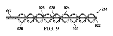
図9は、第3層214の別の例の断面図であり、いくつかの実施形態に関連付けることができるさらなる詳細を示す。たとえば、図9の第3層214は、第3シートを含み、多シート構成を形成することができ、そこでは、第3シートは、第1シートと第2シートとの間に配置されて、材料の第3シートの一部によって分離された2つの半球状部分によって形成された、概して球形の形状であり得る閉鎖セルを形成する。たとえば、第3層214は、複数の閉鎖セル924を画定する封止領域926を形成するように第3シート928に結合又は接合された内面を有する、ポリマーフィルムのシート922及びシート923を含むことができる。閉鎖セル924は、形状が概して球状であり、第3シート928の一部によって分離される2つの半球状部分によって形成される。シート922及びシート923は、たとえば、溶融(たとえば、RF、超音波及び熱)、ホットメルト及び溶剤の両方を用いる接着剤、プレス加工技法を含む種々の異なる方法を使用して、第3シート928に結合又は接合することができる。第3シート928は、ポリマーフィルムから形成することができ、閉鎖セル924の2つの半球状部分の間の空気流を可能にするように穿孔することも可能である。第3シート928がポリマー材料から形成される場合、第3シート928は、ウィッキング(吸上げ)能力を提供するようにテクスチャ加工することも可能である。第3シート928はまた、閉鎖セル924内にウィッキングを提供するようにポリエステル材料から形成することも可能であり、さらなるウィッキング能力を提供するようにポリエステル材料内にフロック加工された繊維をさらに含むことができる。第3シート928はまた、抗菌層、又は第3シート928にコーティングされた抗菌物質も含むことができる。
FIG. 9 is a cross-sectional view of another example of
いくつかの実施形態では、図9の第3層214はまた、シート922及び923のうちのいずれか又は両方の1つ又は複数の表面に、テクスチャ加工表面特徴も含むことができる。テクスチャ加工表面特徴は、図7のテクスチャ加工表面特徴に関して考察したように、突出部又はくぼみであり得る。たとえば、第3層214は、シート922の外面に、より具体的には閉鎖セル924の表面にエンボス加工された突起又はこぶ状部929を含むことができ、その結果、第3層214が組織部位に位置決めされた場合、こぶ状部929は組織部位と接触する。
In some embodiments, the
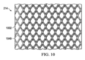
図10は、第3層214の別の例の断面図であり、いくつかの実施形態に関連付けることができるさらなる詳細を示す。たとえば、平坦とすることができ、使用されるときに組織部位に面するものとすることができる、第1シート1002の外面に、複数の異なる性状又は形状を形成することができる。1つの例示的な実施形態では、第1シート1002の外面に、織パターンで格子1049をエンボス加工し又は押出成形することができる。格子1049のパターンは、図示する菱形パターンのような種々の形状を有することができる。第3層214を通るか又は第3層214に沿った流体の流れを促進し、及び/又は組織部位の肉芽形成を促進するために、第1シート1002、又は第3層214の他の開示する実施形態の第1シートの表面に、多くのタイプの突出部又は格子を形成することができることが理解されるべきである。さらに、こうした突出部又は格子のうちの任意のものは、エンボス加工、溶接、又は他の任意の同様のタイプの結合機構によって形成することができることが理解されるべきである。
FIG. 10 is a cross-sectional view of another example of
図11は、第3層1100の別の例の概略図であり、いくつかの実施形態に関連付けることができるさらなる詳細を示す。第3層1100は、上述した第3層214の実施形態と同様であり得るが、陰圧の印加の結果として第3層1100に加えられる付着力をより適切に分散させるように、相互接続された閉鎖セルから形成されたチャンバをさらに含むことができ、それは、チャンバの容積が個々の閉鎖セルの容積より大きいためである。一実施形態では、図11に示すように、第3層1100はシート1102及びシート1103を含み、それらの各々は、複数の閉鎖セル1104を画定するパターンで互いに結合された内面を有するポリマーフィルムであり得る。シート1102及び1103は、互いに封止して、閉鎖セル1104を画定する封止領域1106を形成することができる。封止領域1106はまた、流体が第3層1100を通って流れるための経路を提供するように穿孔することも可能である。1つの例示的な実施形態では、封止領域1106は、第3層1100を通る流体の流れを可能にするようにシート1102及び1103の両方を通って延在する、封止領域1106において閉鎖セル1104の間に形成されている複数のアパーチャ1105を備えることができる。第3層1100はまた、閉鎖チャンバを形成するように閉鎖セル1104のうちの少なくとも2つを流体的に結合する複数の通路1108も備えることができる。一実施形態例では、閉鎖チャンバ1148は、図11に示すように、通路1108によって流体的に結合された1つの行において、閉鎖セル1104のすべてによって形成されている。閉鎖チャンバ1148は、図11に同様に示すように、他の6つの行の各々に形成することができる。任意のパターンの閉鎖セルによる閉鎖チャンバの構造は、第3層1100に加えられる付着力を第3層1100にわたってより等しく分散させることができる。
FIG. 11 is a schematic diagram of another example of a
図12は、第3層1100の別の例の断面図であり、いくつかの実施形態に関連付けることができるさらなる詳細を示す。たとえば、図12の第3層1100は、複数の閉鎖セル1114を画定するパターンで互いに結合された内面を有する、ポリマーフィルムの2つのシート、すなわちシート1112及びシート1113を含むことができる。シート1112及び1113は、形状が概して半球状である閉鎖セル1114を画定する封止領域において互いに封止することができる。第3層1100はまた、閉鎖チャンバ1158を形成するように閉鎖セル1114を相互接続する複数の通路1118も備えることができる。閉鎖チャンバ1158は、図12に示すように、封止領域の一方の側のみから延在するように、シート1112及び1113のうちの一方のみに形成することができる。
FIG. 12 is a cross-sectional view of another example of a
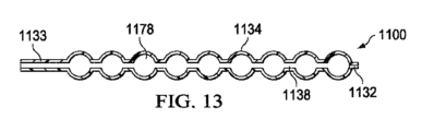
図13は、第3層1100の別の例の断面図であり、いくつかの実施形態に関連付けることができるさらなる詳細を示す。たとえば、図13の第3層1100は、複数の閉鎖セル1134を画定するパターンで互いに結合された内面を有する、ポリマーフィルムの2つのシート、すなわちシート1132及びシート1133を含むことができる。シート1132及び1133は、形状が概して球状である閉鎖セル1134を画定する封止領域において互いに封止することができる。第3層1100はまた、閉鎖チャンバ1178を形成するように閉鎖セル1134を相互接続する複数の通路1138も備えることができる。閉鎖チャンバ1178は、封止領域の両側から延在するように、シート1132及び1133の両方に形成され、封止領域の一方の側のみから延在する閉鎖チャンバ1158より高い可撓性及び緩衝作用を提供する。
FIG. 13 is a cross-sectional view of another example of a
図14は、第3層1100の別の例の断面図であり、いくつかの実施形態に関連付けることができるさらなる詳細を示す。たとえば、図14の第3層1100は、複数の閉鎖セル1124を画定する封止領域を形成するように第3シート1128に結合又は接合された内面を有する、ポリマーフィルムの2つのシート、すなわちシート1122及びシート1123を含むことができる。閉鎖セル1124は、形状が概して球状であり、第3シート1128の一部によって分離されている2つの半球状部分によって形成されている。シート1122及び1123は、たとえば、溶融(たとえば、RF、超音波及び熱)、ホットメルト及び溶剤の両方を用いる接着剤、並びにプレス加工技法を含む種々の異なる方法を使用して、第3シート1128に結合又は接合することができる。第3シート1128は、ポリマーフィルムから形成することができ、閉鎖セル1124の2つの半球状部分の間の空気流を可能にするように穿孔することも可能である。第3シート1128がポリマー材料から形成される場合、ウィッキング能力を提供するように、第3シート1128に対してテクスチャ加工することも可能である。第3シート1128はまた、閉鎖セル1124内でウィッキングを可能にするようにポリエステル材料から形成することも可能であり、さらなるウィッキング能力を提供するようにポリエステル材料内にフロック加工された繊維をさらに含むことができる。第3シート1128はまた、抗菌層、又は第3シート1128上にコーティングされた抗菌物質も含むことができる。図14の第3層1100はまた、閉鎖チャンバ1168を形成するように閉鎖セル1124を相互接続する複数の通路1198も含むことができる。閉鎖チャンバ1168は、封止領域の両側から延在するように、シート1122及び1123の両方に形成される。
FIG. 14 is a cross-sectional view of another example of a
図15は、第3層1200の別の例の概略図であり、いくつかの実施形態に関連付けることができるさらなる詳細を示す。第3層1200は、上述した第3層214の実施形態と同様であり得るが、利用されている療法の特定の形態に好適であり得る、閉鎖セルの異なる配置を含むことができる。図6に関して上述したのは、封止領域606によって画定されるものと同じ平面に形成されたセルの入れ子状パターンを形成するように、個々のセルが交互の行の間で互いにより密に入れ子状にされ得るように、互い違い配置にある閉鎖セル235であった。図15は、互いに近接した複数の閉鎖セル1204を画定するパターンで互いに封止された内面を有する、ポリマーフィルムの2つのシート1202及び1203を含むことができる、第3層1200を示す。しかしながら、閉鎖セル1204の行及び列は互い違いではなく、整列パターンで配置されている。閉鎖セル1204の直径及びピッチに応じて、セル被覆率は、第3層1200の表面積の約10%~約55%の範囲であり得る。シート1202及び1203は、閉鎖セル1204を画定する封止領域1206において互いに封止することができる。この実施形態では、閉鎖セル1204の行及び列は、整列パターンを形成するように一直線に配置されている。第3層1200はまた、上述したように穿孔することができる封止領域1206も含むことができる。いくつかの実施形態では、封止領域1206は、流体が第3層1200を通って流れるのを可能にするように、閉鎖セル1204の間に、シート1202及びシート1203の両方を通って延在する複数のアパーチャ1205を含むことができる。アパーチャ1205は、図6のアパーチャ240と同様の寸法を有することができる。閉鎖セル1204のパターンは、種々の配置を有することができる。
FIG. 15 is a schematic diagram of another example of a
図16は、第3層1300の別の例の概略図であり、いくつかの実施形態に関連付けることができるさらなる詳細を示す。第3層1300は、図15の第3層1200と同様とすることができ、互いに近接した複数の閉鎖セル1304を画定するパターンで互いに封止された内面を有する、ポリマーフィルムの2つのシート1302及び1303を含むことができる。シート1302及び1303は、閉鎖セル1304を画定する封止領域1306において互いに封止することができる。封止領域1306はまた、流体が第3層1300を通って流れるための経路を提供するように穿孔することも可能である。1つの例示的な実施形態では、封止領域1306は、第3層1300を通る流体の流れを可能にするように、シート1302及び1303の両方を通って延在する、封止領域1306において閉鎖セル1304の間に形成されている複数のアパーチャ1305を備えることができる。第3層1300はまた、閉鎖チャンバを形成するように閉鎖セル1304を相互接続する複数の通路1308も備えることができる。1つの例示的な実施形態では、閉鎖チャンバ1348は、図16に示すように通路1308によって流体的に結合された1つの行において、閉鎖セル1304のすべてによって形成される。閉鎖チャンバ1348は、他の6つの行の各々に形成するか、又は、図16に同様に示すように複数の行を含むように形成することができる。任意のパターンでの閉鎖セル1304を含む閉鎖チャンバ1348の構造は、閉鎖セルのみを有する層とは対照的に、第3層1300に加えられる付着力を、第3層1300にわたってより均一に分散させることができる。
FIG. 16 is a schematic diagram of another example of a
再び主に図2を参照すると、ドレッシング104の個々の構成要素は、流体管理に悪影響を与えることなく、たとえば、溶剤若しくは非溶剤接着剤で、又は熱溶接で、互いに接合するか又は他の方法で固定することができる。たとえば、第1層210、第2層212及び第3層214等、組織インタフェース114の層は、互いに貼り合わせることができる。いくつかの実施形態では、層にいかなる穿孔も形成する前に、第1層210、第2層212及び第3層214のうちの任意のもの又はすべての接合面に、低融点(たとえば、約60℃)ホットメルト接着剤メッシュを付与することができる。そして、フィルム層であり得る層を、比較的低い圧縮及び加熱により互いに貼り合わせて、接合を完了するためにホットメルトメッシュを軟化させることができる。さらに又は別法として、組織インタフェース114及びドレッシング104の層を、RF、超音波又は熱を使用して、テクスチャ加工された「スポット溶接」パターンが形成されるようにアレイ又はパターンで合わせて溶接することができる。
Referring again primarily to FIG. 2, the individual components of the dressing 104 may be joined together, for example, with solvent or non-solvent adhesives, or with heat welding, or otherwise, without adversely affecting fluid management. It can be fixed with. For example, the layers of
カバー116、第1層210、第2層212及び第3層214又はさまざまな組合せ等、ドレッシング104の個々の構成要素は、適用前に又はインサイチュで組み立てることができる。たとえば、いくつかの実施形態では、カバー116は第1層210に貼り合わせることができ、第2層212は、カバー116と反対側で第1層210に貼り合わせることができる。さらに、第3層214は、第1層210とは反対側で第2層212に貼り合わせることができる。いくつかの実施形態では、組織インタフェース114の1つ又は複数の層は同一の広がりを有することができる。たとえば、第1層210、第2層212及び第3層214は、互いの縁と同一平面で切断され、したがって、3つのすべての層の縁を露出させることができる。他の実施形態では、第1層210、第2層212及び第3層214のうちの任意の1つは、他の層のうちの任意のもの縁にオーバーラップすることができる。いくつかの実施形態では、ドレッシング104は、単一の複合ドレッシングとして提供することができる。たとえば、第2層212及び第3層214は、第1層210の一部の間に位置決めすることができ、第1層210の一部分をカバー116に結合することができ、第1層210の別の部分を、組織部位に面するように構成することができる。
Individual components of dressing 104, such as
使用時、リリースライナ250(含まれる場合)を除去して第1層210を露出させることができ、第1層210は、組織部位、特に表面組織部位及び隣接する表皮内に、それにわたり、その上に又は他の方法でそれに近接して配置することができる。第1層210は、第2層212と組織部位及び隣接する表皮との間に挿入することができ、それにより、第2層212又は第3層214との相互作用を実質的に低減させるか又はなくすことができる。たとえば、表面創傷(創傷の縁を含む)及び無傷の表皮の上に、第1層210を配置することができる。表面創傷の治療又は表面創傷上のドレッシング104の配置は、ドレッシング104を身体の表面にすぐ隣接して、又は、身体の表面の少なくとも一部の上に延在するように、配置することを含む。表面創傷の治療は、ドレッシング104を体内に完全に又は身体の表面の下に完全に配置することは含まない可能性がある。第1層210、第2層212及び第3層214の周囲で、組織部位の周縁の表皮等、取付面に、カバー116を封止することができる。
In use, the release liner 250 (if included) can be removed to expose the
組織インタフェース114、カバー116又は両方の幾何学的形状及び寸法は、特定の応用又は解剖学的構造に適合するように変更することができる。たとえば、組織インタフェース114及びカバー116の幾何学的形状又は寸法は、組織部位に且つ組織部位の周囲に、肘又は踵等の封止が困難な解剖学的表面に対して有効且つ確実なシールを提供するように適合させることができる。さらに又は別法として、寸法は、組織部位における上皮細胞の移動及び増殖を促進し、肉芽組織の内部成長の可能性を低減させるように、第1層210に対する表面積を増大させるように変更することができる。
The geometry and dimensions of
さらに、ドレッシング104は、再適用又は再配置により、ドレッシング104又は組織部位における折目又は他の不連続性によってもたらされる可能性がある漏れを、低減させるか又はなくすのを可能にすることができる。漏れを修正することができることにより、いくつかの実施形態では、治療の信頼性を向上させ、電力消費量を低減させることができる。 Additionally, the dressing 104 may allow reapplication or repositioning to reduce or eliminate leakage that may be caused by folds or other discontinuities in the dressing 104 or the tissue site. . The ability to correct leaks can, in some embodiments, improve treatment reliability and reduce power consumption.
したがって、図2の例におけるドレッシング104は、外部環境から実質的に隔離された、組織部位に近接する密閉された治療環境を提供することができ、陰圧源102は、密閉された治療環境において減圧することができる。密閉された環境における陰圧は、第2層212及び/又は第3層214を第1層210内に押し込むことができ、それにより、いくつかの実施形態では、組織部位においてマクロひずみ及びマイクロひずみを引き起こすことができる、不均一な、粗い又はぎざぎざの輪郭を提供するように、第1層210の表面を変形させることができる。
Thus, the dressing 104 in the example of FIG. 2 can provide a closed treatment environment proximate the tissue site that is substantially isolated from the external environment, and the
まだ構成されていない場合、ドレッシングインタフェース260は、アパーチャ265の上に配置し、カバー116に取り付けることができる。流体伝導体255は、ドレッシングインタフェース260に且つ陰圧源102に流体的に結合することができる。
If not already configured, dressing
組織インタフェース114を通して印加される陰圧は、第1層210において流体制限部220にわたって負の差圧をもたらすことができ、それにより、流体制限部220を開放又は拡張することができる。たとえば、流体制限部220が、第1層210を通して穿孔を備えることができるいくつかの実施形態では、穿孔にわたる圧力勾配により、ダックビル弁の動作と同様に、第1層210の隣接する材料を歪ませ、穿孔の寸法を、その中を通る液体移動を可能にするように増大させることができる。流体制限部220を開放することにより、滲出物及び他の液体の、流体制限部220を通る第2層212、第3層214及び容器106内への移動を可能にすることができる。陰圧源102が除去されるか又はオフにされると、流体制限部220にわたる差圧は消失することができ、流体制限部220は、歪んでいない又は静止した状態に戻り、滲出物又は他の液体が第1層210を通って組織部位まで移動するのを防止するか又はその移動する戻り速度を低減させることができる。
Negative pressure applied through
さらに又は別法として、ドレッシング104に滴下溶液又は他の流体を分配することができ、それにより、組織インタフェース114において圧力を上昇させることができる。組織インタフェース114における圧力の上昇により、第1層210において流体制限部220にわたって正の差圧をもたらすことができ、それにより、滴下溶液又は他の流体が組織部位に分配されるのを可能にするように流体制限部220をそれらの静止状態から開放又は拡張することができる。
Additionally or alternatively, a drip solution or other fluid can be dispensed into the dressing 104, thereby increasing the pressure at the
図17は、図1の組織インタフェース114の別の例の組立図であり、いくつかの実施形態に関連付けることができるさらなる詳細を示す。図17の例では、第3層214は、第2層212の間に配置することができ、第1層210の間にも配置することができる。図17の例では、第3層214は2つの別個の層を含むことができ、別個の層の各々は閉鎖セルを含む。第3層214における閉鎖セルのさらなる層が、組織インタフェース114に対する適合した圧迫感を増大させることができる。閉鎖セルの2つの別個の層は、互いに近接して又は互いに接して位置決めすることができる。第3層214の2つの層は、第2層212の間に位置決めすることができ、第2層212は第3層214の2つの面に隣接して位置決めされる。いくつかの実施形態では、たとえば、第2層212は、第3層214の2つの面に貼り合わせるか又は他の方法で機械的に接合することができる。さらに、第1層210は、第2層212の2つの面に隣接して配置することができ、いくつかの実施形態では、第1層210は、第2層212の2つの面に貼り合わせるか又は他の方法で接合することができる。第1層210、第2層212及び第3層214は、第2層212が第1層210及び第3層214と隣接しかつ接触するように、積層することができる。第2層212はまた、いくつかの実施形態では、第1層210、第3層214又は両方に接合することも可能である。
FIG. 17 is an assembled view of another example of the
図17の実施形態では、第3層214の2つの別個の層の各々は、別個の層の各々の閉鎖セル235が互いに反対の方向に面しているように向けることができる。たとえば、第3層214の2つの層のうちの第1層における閉鎖セル235は、組織インタフェース114の第1側に向かって上向きに面しているか又は突出していることが可能であり、第3層214の2つの層のうちの第2層の閉鎖セル235は、組織インタフェース114の第2側に向かって下向きに面しているか又は突出していることが可能である。他の実施形態(図示せず)では、第3層214の2つの層は、閉鎖セルが互いに面しているように向けることができる。たとえば、第3層214は、互いに面する半球状閉鎖セルを有する2つの層を含むことができる。
In the embodiment of FIG. 17, each of the two separate layers of
図18は、図1の組織インタフェース114の別の例の組立図であり、いくつかの実施形態に関連付けることができるさらなる詳細を示す。図18の組織インタフェース114は、図17の組織インタフェース114と同様であり得るが、第3層214が、互いに近接して又は隣接して位置決めすることができる3つの別個の層を備えるという点が異なる。第3層214の3つの別個の層は、第1層210の間に位置決めすることができる第2層212の間に位置決めすることができる。図18の実施形態では、第3層214の第1層及び第2層の閉鎖セル235が、組織インタフェース114の第1側に向かって上向きに面しているか又は突出していることが可能である一方で、第3層214の3つの層のうちの第3層の閉鎖セル235が、組織インタフェース114の第2側に向かって下向きに面しているか又は突出していることが可能であるように、第3層214の3つの別個の層を向けることができる。他の実施形態では、第3層214の3つの層は、閉鎖セル235が種々の異なる組合せで向けられるように位置決めすることができる。
FIG. 18 is an assembled view of another example of the
図19は、図1の組織インタフェース114の別の例の組立図である。図19の例では、第2層212は、第1層210と第3層214との間に配置される。図19に示す組織インタフェース114の実施形態は、第3層214が組織部位に直接接して配置されているように適合されるというものであり得る。たとえば、図19の組織インタフェース114は、可逆的な又は面に依存しない構造とは対照的に、面特有であり得る。しかしながら、第1層210が組織部位に接して位置決めされるように、図19の組織インタフェース114の向きを反転させることができることもあり得る。組織インタフェース114のいずれの層が組織部位に面するかに応じて、図19の組織インタフェース114は、組織部位からの異なる反応をもたらすことができる。さらに、閉鎖セル235が上向き又は下向きのいずれかに面するように、第3層214を位置決めすることができる。
FIG. 19 is an assembled view of another example of the
図19の例では、第3層214の閉鎖セル235は、第3層214の内向き面に位置決めすることができ、したがって、閉鎖セル235を第2層212と接触するように配置することができる。閉鎖セル235は、治療セッション中に陰圧及び滴下液体の両方に対して流体の流れのための通路を提供するように、第2層212とともに複数の流路を形成することができる。第3層214のアパーチャ240は、陰圧の伝達及び流体の移動を容易にするために空隙があるように、第3層214と第2層212との間に形成された流路を流体的に結合することができる。組織インタフェース114の他の実施形態例に関して上述したように、図19の第3層の閉鎖セル235の間に配置されたアパーチャ240は、直径が約1mm以上とすることができる。
In the example of FIG. 19, the
第3層214に陰圧が印加される場合、第3層214をカバー116の下で圧縮することができ、それにより、カバー116は組織部位に向かってつぶれることができる。たとえば、組織インタフェース114の向きが、第3層214がカバー116に隣接するようなものである実施形態では、閉鎖セル235の上面に対するカバー116の下向きのつぶれ力は、閉鎖セル235を介して伝達することができる。いくつかの実施形態では、第3層214はこぶ状部又は突起を含むことができる。たとえば、こぶ状部が第3層214から外向きに延在して組織部位と接触するように、組織部位において第3層214を配置することができる。こぶ状部は、第3層214の外面と組織部位との間に空隙を形成することができる。こぶ状部は、肉芽形成を促進するために、組織部位におけるマイクロひずみを増大させるように、組織部位内に押し込むことができる。閉鎖セル235は、第3層214への陰圧の印加中に形状を変化させるか又は幾分か平坦になる可能性があるが、閉鎖セル235の容積は実質的に一定のままであり得る。第3層214は、組織部位に陰圧療法を提供し続けるように、流路を通して流体の流れを維持しながら、こぶ状部に下向きの力を伝達することができる。したがって、第3層214は、こぶ状部に付着力を加えることができ、それにより、流路及び空隙を介して組織部位との流体連通を維持しながら肉芽形成を促進することができる。閉鎖セル235の可撓性は、治療中に陰圧が増大し及び/又は変更される際に、こぶ状部の移動も容易にすることができ、その結果、さらなる移動が肉芽形成をさらに促進することができる。
When negative pressure is applied to the
図20は、図1の組織インタフェース114の別の例の組立図である。図20の例では、組織インタフェース114は、第1層210と、第1層210に隣接して配置された第2層212とを含むことができる。したがって、いくつかの実施形態では、組織インタフェース114は、組織部位に接して配置される2層構造の形態であり得る。組織部位の特定の必要に応じて、図20の例としての組織インタフェース114の2層構造は、第1層210又は第2層212のいずれかが組織部位の表面に接するように配置することができる。さらに、特定の実施形態に応じて、第2層212の向きを反転させることができる。たとえば、いくつかの実施形態では、図20の例に示すように、ブリスタ225が第1層210から離れる方向に突出することができるように、第1層210に対して第2層212を向けることができる。他の実施形態では、ブリスタ225が第1層210に面するか又は接触するように、第1層210に対して第2層212を向けることができる。
FIG. 20 is an assembled view of another example of the
図21は、図1の組織インタフェース114の別の例の組立図である。図20に示す例と同様に、図21の組織インタフェース114は、組織部位に接して配置される2層構造の形態であり得る。図21の組織インタフェース114は、第1層210と、第1層210に隣接して配置された第3層214とを含むことができる。図21の組織インタフェース114は、第1層210又は第3層214のいずれかが組織部位の表面に接するように配置することができる。図20に関して言及したように、閉鎖セル235が(図21に示すように)第1層210から離れる方向に延在するか又は第1層210に面するように、図21の組織インタフェース114の第3層214の向きを反転させることができる。
FIG. 21 is an assembled view of another example of the
いくつかの追加の実施形態では、組織インタフェース114の第1層210及び第3層214の特徴をある程度まで組み合わせることができる。たとえば、通常、ポリマーフィルムの2つのシートから形成することができる、第3層214は、ポリマーフィルムの2つのシートのうちの一方として第1層210を含むことができる。こうした場合、第3層214の閉鎖セル235は、第1側の第1層210と、第2側のポリマーフィルムの第2シートとの間に形成するか、又はそれらによって封じ込めることができる。第1層210の流体制限部220は、閉鎖セル235の間に又は周囲に位置決めすることができる。
In some additional embodiments, the features of the
特定の応用又は提示される組織部位に応じて、ドレッシング104、特に組織インタフェース114のさらなる又は代替的な実施形態を提供することができる。たとえば、いくつかの実施形態では、第1層210、第2層212及び第3層214等、組織インタフェース114の層のうちの1つ又は複数は、たとえば、ZOTEFOAM材料等の独立気泡フォーム等、代替的な材料を含むことができる。独立気泡フォーム材料は、自立式であるが、可撓性も有することができ、閉鎖セルのみではなく、材料に開放空気ポケットが形成されるのも可能にすることができる。こうしたフォーム材料の複数の層を含むことにより、組織インタフェース114の構築を簡略化するという点でいくつかの利益を提供することができる。
Additional or alternative embodiments of the dressing 104, and particularly the
組織インタフェース114のいくつかの他の実施形態例では、第3層214に、第3層214の表面にわたって、後に膨張して閉じ込められた空気ポケットを提供することができる成分を印刷することによって形成することができる、閉鎖セルを設けることができる。たとえば、第3層214の表面にわたって、発泡剤を含むポリマー溶液、懸濁液又は乳濁液を印刷することができる。第3層214における印刷された成分が乾燥すると、熱を加えて発泡剤を活性化させ、印刷成分を膨張させることができる。閉鎖セルを形成するこの方法は、1回の加熱プロセスで、複数の平坦なフィルム層が貼り合わされ、その後、層が膨張もする間に互いに接合されるのを可能にすることにより、組織インタフェース114のさまざまな層の貼合せプロセスを簡略化するのに役立つことができる。
In some other example embodiments of the
組織インタフェース114の特定の実施形態に応じて、組織インタフェース114のさまざまなフィルム層を合わせて接合する異なる機構を使用することができる。たとえば、フィルムラミネート、たとえばポリエチレン/イオノマーラミネートから、組織インタフェース114のフィルム層を形成することができ、そこでは、イオノマーは、低熱で軟化する低融点ポリマーであり、したがって、組織インタフェース114の異なるフィルム層を合わせて接合することができる。したがって、場合により、別個に付与されるホットメルトメッシュの必要をなくすことができる。さらに又は別法として、組織インタフェース114のさまざまなフィルム層の接合面に、フィルム層を貼り合わせる直前に、感圧又は感熱接着剤を噴霧することができる。さらに、組織インタフェース114のさまざまな層を合わせて接合するために低融点ホットメルトメッシュが使用される実施形態では、さらなる熱安定性を提供するように、ホットメルトメッシュを熱架橋性とすることができる。さらに、接合強度を増大させ熱安定性を向上させるために、上述したさまざまな接着剤のすべてを、たとえばガンマ放射線により、架橋を受けやすくすることができる。
Depending on the particular embodiment of
本明細書に記載したシステム、装置及び方法は、著しい利点を提供することができる。たとえば、ドレッシング104のいくつかの実施形態は、適用が簡単であり、且つ、ドレッシングを適用し除去するために必要な時間を短縮させることができる、陰圧療法で使用される組織ドレッシングを提供することができる。ドレッシング材料の不適切な適用に関連する廃棄物も減少させることができる。いくつかの実施形態では、組織インタフェース114及び場合によりドレッシング104は、組織部位に適用するために術者が容易に切断し、成形し、カスタマイズすることができる、完全に一体化した陰圧療法ドレッシングであり得る。従来のドレッシングのいくつかの例と異なり、組織インタフェース114又はドレッシング104は、組織の内部成長を可能にし、したがってドレッシング除去中の組織部位の破壊をもたらす可能性がある、フォーム又は他の材料の露出なしに、切断し成形することができる。ドレッシング104は、陰圧と滴下療法に関連して提供される治療流体との良好なマニホールド化を含む、組織部位における組織との良好な相互作用を提供することができる。たとえば、組織インタフェース114内に、第2層212及び第3層214等、マニホールド化又は離隔層を含めることにより、空間及び湾曲に沿うことができる圧縮性の軟質材料充填材による良好なマニホールド化を提供することができる。したがって、ドレッシング104は、本技術分野における従来のドレッシングで行われる可能性があるように必ずしも組織部位と一体化することなく、有益な肉芽形成と、組織部位との低外傷且つ高密閉性接合を提供することができる。
The systems, devices and methods described herein can provide significant advantages. For example, some embodiments of the dressing 104 provide a tissue dressing used in negative pressure therapy that is easy to apply and can reduce the time required to apply and remove the dressing. be able to. Waste associated with improper application of dressing materials can also be reduced. In some embodiments, the
組織インタフェース114に異なる層を含めることにより、中~深創傷等、より深い組織部位を充填する構造を提供する一方で、組織インタフェース114及びドレッシング104内への破壊的な内部成長を実質的に低減させるか又は防止することができる。ドレッシング104のこれらの特徴は、深創傷又は穿掘領域の腔内に配置するために特に有利である一方で、容易な除去の可能性を維持することができる。場合により、ドレッシング104は、最大7日間、又はさらにはそれより長く、組織部位において適所に安全にとどまることができる、創傷充填材を提供することができる。さらに、ドレッシング104の複数の層を透明材料から形成することができ、それにより、使用者に対し、感染又は他の状態に関連する組織部位の任意の色又は他の態様を観察するために組織部位が見える状態を維持することができる。
The inclusion of different layers in the
いくつかの例示的な実施形態で示したが、当業者は、本明細書に記載したシステム、装置及び方法が、添付の請求項の範囲内にあるさまざまな変形及び変更が可能であることを理解するであろう。さらに、「又は」等の用語を使用するさまざまな代替例の記載は、文脈から明らかに必要でない限り、相互排他性を必要とせず、「1つの(a)」又は「1つの(an)」という冠詞は、文脈から明らかに必要でない限り、対象を単一の例に限定するものではない。販売、製造、組立又は使用の目的で、構成要素をさまざまな構成で組み合わせるか又は除去することも可能である。たとえば、いくつかの構成では、ドレッシング104、容器106又は両方を、製造又は販売のために他の構成要素から除去又は分離することができる。他の構成例では、コントローラ108はまた、他の構成要素から、独立して製造し、構成し、組み立て又は販売することも可能である。
Although shown in several exemplary embodiments, those skilled in the art will appreciate that the systems, apparatus, and methods described herein are capable of various modifications and variations that are within the scope of the appended claims. you will understand. Furthermore, the recitation of various alternatives using terms such as "or" does not require mutual exclusivity, unless the context clearly requires otherwise. Articles do not limit the subject to a single instance unless the context clearly requires otherwise. The components may also be combined or removed in various configurations for purposes of sale, manufacture, assembly, or use. For example, in some configurations, dressing 104,
添付の特許請求の範囲は、上述した主題の新規性のある且つ進歩性のある態様を示すが、具体的に詳細に記載していないさらなる主題も包含することができる。たとえば、当業者には既知であることから新規性のある且つ進歩性のある特徴を識別するために必要ではない場合、いくつかの特徴、要素又は態様を特許請求の範囲から省略している場合がある。いくつかの実施形態に関連して記載した特徴、要素及び態様はまた、添付の特許請求の範囲によって定義される本発明の範囲から逸脱することなく、省略するか、組み合わせるか、又は、同じ、等価の若しくは同様の目的にかなう代替的な特徴と置き換えることも可能である。 The appended claims, while indicating novel and inventive aspects of the subject matter described above, may also encompass additional subject matter not specifically described in detail. For example, some features, elements or aspects are omitted from the claims if they are known to a person skilled in the art and are therefore not necessary to identify novel and inventive features. There is. Features, elements and aspects described in connection with some embodiments may also be omitted, combined or the same, without departing from the scope of the invention as defined by the appended claims. It is also possible to substitute alternative features that serve equivalent or similar purposes.
Claims (17)
無孔材料の第1フィルムと複数の流体制限部とを備える第1層と、
前記第1層に隣接する第2層であって、無孔材料の第2フィルムを備え、前記第2フィルムが、ブリスタと、前記第2フィルムを通る流体の移動を可能にする第1アパーチャとを有する、第2層と、
無孔材料を備える第3層であって、前記無孔材料が、閉鎖セルと、前記第3層を通る流体の移動を可能にする、前記閉鎖セルの間の第2アパーチャとを有する、第3層と、
前記第2層とは反対側で前記第3層に隣接する第4層であって、無孔材料の第3フィルムを備え、前記第3フィルムが、ブリスタと、前記第4層を通る流体の移動を可能にする第3アパーチャとを有する、第4層と、
前記第3層とは反対側で前記第4層に隣接する第5層であって、無孔材料の第4フィルムと第2の複数の流体制限部とを備える第5層と
を備えることを特徴とするドレッシング。 In dressings used in negative pressure therapy,
a first layer comprising a first film of non-porous material and a plurality of fluid restrictions;
a second layer adjacent the first layer, the second layer comprising a second film of non-porous material, the second film having a blister and a first aperture for allowing movement of fluid through the second film; a second layer having;
a third layer comprising a non-porous material, the non-porous material having closed cells and second apertures between the closed cells to allow movement of fluid through the third layer; 3 layers and
a fourth layer opposite the second layer and adjacent the third layer, the third film comprising a third film of non-porous material, the third film being configured to contain the blister and the flow of fluid through the fourth layer; a fourth layer having a third aperture that allows movement;
a fifth layer adjacent to the fourth layer opposite the third layer, the fifth layer comprising a fourth film of non-porous material and a second plurality of fluid restrictions;
A dressing characterized by comprising.
前記流体制限部が平行な行及び列で前記第1フィルムにわたって分散され、
前記行が中心において約3ミリメートル間隔を空けて配置され、
前記行の各々における前記流体制限部が中心において約3ミリメートル間隔を空けて配置され、
隣接する行における前記流体制限部がずれていることを特徴とするドレッシング。 The dressing according to claim 1,
the fluid restrictions are distributed across the first film in parallel rows and columns;
the rows are spaced about 3 millimeters apart on center;
the fluid restrictions in each of the rows are spaced about 3 millimeters apart on center;
Dressing characterized in that the fluid restrictions in adjacent rows are offset.
前記ブリスタが約2ミリメートル間隔を空けて配置され、
前記ブリスタが約1.5ミリメートルの高さを有し、
前記ブリスタが約1.5ミリメートルの直径を有することを特徴とするドレッシング。 The dressing according to claim 1,
the blisters are spaced about 2 millimeters apart;
the blister has a height of about 1.5 mm;
Dressing characterized in that said blister has a diameter of about 1.5 millimeters.
前記第3層の前記無孔材料が、互いに接合された2つのフィルムを備え、
前記閉鎖セルが、前記2つのフィルムによって画定されていることを特徴とするドレッシング。 The dressing according to claim 1,
the non-porous material of the third layer comprises two films bonded together;
Dressing characterized in that said closed cell is defined by said two films .
前記第3層の前記無孔材料が、互いに接合された2つのフィルムを備え、
前記閉鎖セルが、前記2つのフィルムによって画定されており、
前記2つのフィルムの両方がポリオレフィンを含むことを特徴とするドレッシング。 The dressing according to claim 1,
the non-porous material of the third layer comprises two films bonded together;
the closed cell is defined by the two films ;
A dressing characterized in that both said two films contain polyolefins.
Applications Claiming Priority (13)
| Application Number | Priority Date | Filing Date | Title |
|---|---|---|---|
| US201762516566P | 2017-06-07 | 2017-06-07 | |
| US201762516540P | 2017-06-07 | 2017-06-07 | |
| US201762516550P | 2017-06-07 | 2017-06-07 | |
| US62/516,540 | 2017-06-07 | ||
| US62/516,566 | 2017-06-07 | ||
| US62/516,550 | 2017-06-07 | ||
| US201762565754P | 2017-09-29 | 2017-09-29 | |
| US62/565,754 | 2017-09-29 | ||
| US201762576498P | 2017-10-24 | 2017-10-24 | |
| US62/576,498 | 2017-10-24 | ||
| US201762592950P | 2017-11-30 | 2017-11-30 | |
| US62/592,950 | 2017-11-30 | ||
| PCT/US2018/036021 WO2018226669A1 (en) | 2017-06-07 | 2018-06-05 | Multi-layer wound filler for extended wear time |
Publications (3)
| Publication Number | Publication Date |
|---|---|
| JP2020523076A JP2020523076A (en) | 2020-08-06 |
| JP2020523076A5 JP2020523076A5 (en) | 2022-01-04 |
| JP7356358B2 true JP7356358B2 (en) | 2023-10-04 |
Family
ID=62705772
Family Applications (1)
| Application Number | Title | Priority Date | Filing Date |
|---|---|---|---|
| JP2019566947A Active JP7356358B2 (en) | 2017-06-07 | 2018-06-05 | Multilayer wound filler for long-term wear |
Country Status (7)
| Country | Link |
|---|---|
| US (2) | US11179512B2 (en) |
| EP (1) | EP3634334B1 (en) |
| JP (1) | JP7356358B2 (en) |
| CN (1) | CN110831552B (en) |
| AU (1) | AU2018282193A1 (en) |
| CA (1) | CA3065521A1 (en) |
| WO (1) | WO2018226669A1 (en) |
Families Citing this family (31)
| Publication number | Priority date | Publication date | Assignee | Title |
|---|---|---|---|---|
| GB0808376D0 (en) | 2008-05-08 | 2008-06-18 | Bristol Myers Squibb Co | Wound dressing |
| GB0817796D0 (en) | 2008-09-29 | 2008-11-05 | Convatec Inc | wound dressing |
| GB201020236D0 (en) | 2010-11-30 | 2011-01-12 | Convatec Technologies Inc | A composition for detecting biofilms on viable tissues |
| US9526816B2 (en) | 2010-12-08 | 2016-12-27 | Convatec Technologies Inc. | Wound exudate monitor accessory |
| WO2012078781A1 (en) | 2010-12-08 | 2012-06-14 | Convatec Technologies Inc. | Integrated system for assessing wound exudates |
| WO2013066426A2 (en) | 2011-06-24 | 2013-05-10 | Kci Licensing, Inc. | Reduced-pressure dressings employing tissue-fixation elements |
| GB201115182D0 (en) | 2011-09-02 | 2011-10-19 | Trio Healthcare Ltd | Skin contact material |
| GB2497406A (en) | 2011-11-29 | 2013-06-12 | Webtec Converting Llc | Dressing with a perforated binder layer |
| KR20150099776A (en) | 2012-12-20 | 2015-09-01 | 컨바텍 테크놀러지스 인크 | Processing of chemically modified cellulosic fibres |
| KR20190008199A (en) | 2016-03-30 | 2019-01-23 | 시노보 게엠베하 | Detection of microbial infection in wound |
| CN109310528B (en) | 2016-03-30 | 2021-07-20 | 康沃特克科技公司 | Detecting microbial infection in a wound |
| EP3481360B1 (en) | 2016-07-08 | 2022-03-09 | ConvaTec Technologies Inc. | Fluid flow sensing |
| WO2018009873A1 (en) | 2016-07-08 | 2018-01-11 | Convatec Technologies Inc. | Fluid collection apparatus |
| ES2882336T3 (en) | 2016-07-08 | 2021-12-01 | Convatec Technologies Inc | Flexible negative pressure system |
| EP4285880A3 (en) * | 2018-02-23 | 2024-03-06 | 3M Innovative Properties Company | Dressing with bolster for linear tissue sites |
| CN112105323A (en) | 2018-03-12 | 2020-12-18 | 凯希特许有限公司 | Dressing for use in cabin spaces using different surface features |
| ES1215290Y (en) * | 2018-06-06 | 2018-10-03 | Servicio Cantabro De Salud | Protective dressing of abdominal viscera in negative pressure therapy |
| CN112955100A (en) * | 2018-10-17 | 2021-06-11 | 凯希特许有限公司 | Peel-off and placement dressing with closed cell contact layer |
| US20220168493A1 (en) * | 2019-04-22 | 2022-06-02 | Kci Licensing, Inc. | Transparent Peel And Place Dressing For Negative-Pressure Therapy |
| US20220202620A1 (en) * | 2019-05-08 | 2022-06-30 | Kci Licensing, Inc. | Manifold With Biological Actives For Negative-Pressure Therapy |
| WO2020231360A1 (en) * | 2019-05-10 | 2020-11-19 | HOT, Semih | A two-way vacuum assisted closure system |
| US20220305192A1 (en) * | 2019-06-17 | 2022-09-29 | Kci Licensing, Inc. | Abdominal Negative-Pressure Therapy Dressing With Closed-Loop Force Management Control |
| EP4009929A1 (en) * | 2019-08-06 | 2022-06-15 | KCI Licensing, Inc. | Hand dressing for use with negative pressure wound therapy, negative pressure wound therapy system comprising the same, method for controlling a pump coupled to said dressing |
| WO2021033052A1 (en) * | 2019-08-22 | 2021-02-25 | Kci Licensing, Inc. | System and method for wound dressing moisture management using forced airflow |
| WO2021059126A1 (en) * | 2019-09-24 | 2021-04-01 | Kci Licensing, Inc. | Dressing system for use on deep wounds with reduced in-growth and extended wear time |
| US11771819B2 (en) | 2019-12-27 | 2023-10-03 | Convatec Limited | Low profile filter devices suitable for use in negative pressure wound therapy systems |
| US11331221B2 (en) | 2019-12-27 | 2022-05-17 | Convatec Limited | Negative pressure wound dressing |
| WO2022123354A1 (en) * | 2020-12-07 | 2022-06-16 | Kci Manufacturing Unlimited Company | Dressings for negative-pressure therapy with transparent layers |
| US20240000617A1 (en) * | 2020-12-07 | 2024-01-04 | Kci Manufacturing Unlimited Company | Deformable dressing for negative-pressure therapy |
| WO2022175764A1 (en) * | 2021-02-18 | 2022-08-25 | Kci Manufacturing Unlimited Company | Dressing interface having bubble supports with optional break-lines |
| WO2023092202A1 (en) * | 2021-11-24 | 2023-06-01 | Moreira Costa De Souza Gustavo | Dressing for negative pressure wound therapy |
Citations (4)
| Publication number | Priority date | Publication date | Assignee | Title |
|---|---|---|---|---|
| WO2011121127A1 (en) | 2010-04-03 | 2011-10-06 | Birgit Riesinger | Wound care article adapted to different through-flow speeds of the wound exudate |
| JP2012500077A (en) | 2008-08-18 | 2012-01-05 | イノテック エーエムディー リミティド | High pressure wound dressing and method |
| JP2013521886A (en) | 2010-03-11 | 2013-06-13 | ケーシーアイ ライセンシング インコーポレイテッド | Dressing, system and method for treating tissue sites |
| US20160144085A1 (en) | 2013-06-18 | 2016-05-26 | Mölnlycke Health Care Ab | Fluid transport dressing |
Family Cites Families (250)
| Publication number | Priority date | Publication date | Assignee | Title |
|---|---|---|---|---|
| US1355846A (en) | 1920-02-06 | 1920-10-19 | David A Rannells | Medical appliance |
| US2547758A (en) | 1949-01-05 | 1951-04-03 | Wilmer B Keeling | Instrument for treating the male urethra |
| US2632443A (en) | 1949-04-18 | 1953-03-24 | Eleanor P Lesher | Surgical dressing |
| GB692578A (en) | 1949-09-13 | 1953-06-10 | Minnesota Mining & Mfg | Improvements in or relating to drape sheets for surgical use |
| US2682873A (en) | 1952-07-30 | 1954-07-06 | Johnson & Johnson | General purpose protective dressing |
| NL189176B (en) | 1956-07-13 | 1900-01-01 | Hisamitsu Pharmaceutical Co | PLASTER BASED ON A SYNTHETIC RUBBER. |
| US2969057A (en) | 1957-11-04 | 1961-01-24 | Brady Co W H | Nematodic swab |
| US3066672A (en) | 1960-09-27 | 1962-12-04 | Jr William H Crosby | Method and apparatus for serial sampling of intestinal juice |
| US3367332A (en) | 1965-08-27 | 1968-02-06 | Gen Electric | Product and process for establishing a sterile area of skin |
| US3520300A (en) | 1967-03-15 | 1970-07-14 | Amp Inc | Surgical sponge and suction device |
| US3568675A (en) | 1968-08-30 | 1971-03-09 | Clyde B Harvey | Fistula and penetrating wound dressing |
| US3654060A (en) | 1969-12-29 | 1972-04-04 | Fibre Products Lab Inc | Absorbent slitted multi-ply films |
| US3682180A (en) | 1970-06-08 | 1972-08-08 | Coilform Co Inc | Drain clip for surgical drain |
| BE789293Q (en) | 1970-12-07 | 1973-01-15 | Parke Davis & Co | MEDICO-SURGICAL DRESSING FOR BURNS AND SIMILAR LESIONS |
| US3826254A (en) | 1973-02-26 | 1974-07-30 | Verco Ind | Needle or catheter retaining appliance |
| US3930096A (en) | 1974-04-15 | 1975-12-30 | Deering Milliken Res Corp | Composite porous fabric-impervious film article |
| DE2527706A1 (en) | 1975-06-21 | 1976-12-30 | Hanfried Dr Med Weigand | DEVICE FOR THE INTRODUCTION OF CONTRAST AGENTS INTO AN ARTIFICIAL INTESTINAL OUTLET |
| DE2640413C3 (en) | 1976-09-08 | 1980-03-27 | Richard Wolf Gmbh, 7134 Knittlingen | Catheter monitor |
| NL7710909A (en) | 1976-10-08 | 1978-04-11 | Smith & Nephew | COMPOSITE STRAPS. |
| GB1562244A (en) | 1976-11-11 | 1980-03-05 | Lock P M | Wound dressing materials |
| US4080970A (en) | 1976-11-17 | 1978-03-28 | Miller Thomas J | Post-operative combination dressing and internal drain tube with external shield and tube connector |
| US4139004A (en) | 1977-02-17 | 1979-02-13 | Gonzalez Jr Harry | Bandage apparatus for treating burns |
| US4184510A (en) | 1977-03-15 | 1980-01-22 | Fibra-Sonics, Inc. | Valued device for controlling vacuum in surgery |
| US4173046A (en) | 1977-08-10 | 1979-11-06 | Gallagher John P | Absorptive patient underpad |
| US4165748A (en) | 1977-11-07 | 1979-08-28 | Johnson Melissa C | Catheter tube holder |
| US4245637A (en) | 1978-07-10 | 1981-01-20 | Nichols Robert L | Shutoff valve sleeve |
| SE414994B (en) | 1978-11-28 | 1980-09-01 | Landstingens Inkopscentral | VENKATETERFORBAND |
| GB2047543B (en) | 1978-12-06 | 1983-04-20 | Svedman Paul | Device for treating tissues for example skin |
| US4266545A (en) | 1979-04-06 | 1981-05-12 | Moss James P | Portable suction device for collecting fluids from a closed wound |
| US4284079A (en) | 1979-06-28 | 1981-08-18 | Adair Edwin Lloyd | Method for applying a male incontinence device |
| US4261363A (en) | 1979-11-09 | 1981-04-14 | C. R. Bard, Inc. | Retention clips for body fluid drains |
| US4569348A (en) | 1980-02-22 | 1986-02-11 | Velcro Usa Inc. | Catheter tube holder strap |
| US4480638A (en) | 1980-03-11 | 1984-11-06 | Eduard Schmid | Cushion for holding an element of grafted skin |
| US4297995A (en) | 1980-06-03 | 1981-11-03 | Key Pharmaceuticals, Inc. | Bandage containing attachment post |
| US4333468A (en) | 1980-08-18 | 1982-06-08 | Geist Robert W | Mesentery tube holder apparatus |
| US4465485A (en) | 1981-03-06 | 1984-08-14 | Becton, Dickinson And Company | Suction canister with unitary shut-off valve and filter features |
| US4392853A (en) | 1981-03-16 | 1983-07-12 | Rudolph Muto | Sterile assembly for protecting and fastening an indwelling device |
| US4373519A (en) | 1981-06-26 | 1983-02-15 | Minnesota Mining And Manufacturing Company | Composite wound dressing |
| US4392858A (en) | 1981-07-16 | 1983-07-12 | Sherwood Medical Company | Wound drainage device |
| US4419097A (en) | 1981-07-31 | 1983-12-06 | Rexar Industries, Inc. | Attachment for catheter tube |
| AU550575B2 (en) | 1981-08-07 | 1986-03-27 | Richard Christian Wright | Wound drainage device |
| SE429197B (en) | 1981-10-14 | 1983-08-22 | Frese Nielsen | SAR TREATMENT DEVICE |
| DE3146266A1 (en) | 1981-11-21 | 1983-06-01 | B. Braun Melsungen Ag, 3508 Melsungen | COMBINED DEVICE FOR A MEDICAL SUCTION DRAINAGE |
| US4551139A (en) | 1982-02-08 | 1985-11-05 | Marion Laboratories, Inc. | Method and apparatus for burn wound treatment |
| US4475909A (en) | 1982-05-06 | 1984-10-09 | Eisenberg Melvin I | Male urinary device and method for applying the device |
| DE3361779D1 (en) | 1982-07-06 | 1986-02-20 | Dow Corning | Medical-surgical dressing and a process for the production thereof |
| NZ206837A (en) | 1983-01-27 | 1986-08-08 | Johnson & Johnson Prod Inc | Thin film adhesive dressing:backing material in three sections |
| EP0122085B1 (en) | 1983-04-06 | 1987-06-24 | Smith and Nephew Associated Companies p.l.c. | Dressing |
| US4548202A (en) | 1983-06-20 | 1985-10-22 | Ethicon, Inc. | Mesh tissue fasteners |
| US4540412A (en) | 1983-07-14 | 1985-09-10 | The Kendall Company | Device for moist heat therapy |
| US4543100A (en) | 1983-11-01 | 1985-09-24 | Brodsky Stuart A | Catheter and drain tube retainer |
| US4525374A (en) | 1984-02-27 | 1985-06-25 | Manresa, Inc. | Treating hydrophobic filters to render them hydrophilic |
| GB2157958A (en) | 1984-05-03 | 1985-11-06 | Ernest Edward Austen Bedding | Ball game net support |
| US4897081A (en) | 1984-05-25 | 1990-01-30 | Thermedics Inc. | Percutaneous access device |
| US5215522A (en) | 1984-07-23 | 1993-06-01 | Ballard Medical Products | Single use medical aspirating device and method |
| GB8419745D0 (en) | 1984-08-02 | 1984-09-05 | Smith & Nephew Ass | Wound dressing |
| US4872450A (en) | 1984-08-17 | 1989-10-10 | Austad Eric D | Wound dressing and method of forming same |
| GB8422492D0 (en) | 1984-09-06 | 1984-10-10 | Smith & Nephew Ass | Adhesive dressing |
| US4826494A (en) | 1984-11-09 | 1989-05-02 | Stryker Corporation | Vacuum wound drainage system |
| US4655754A (en) | 1984-11-09 | 1987-04-07 | Stryker Corporation | Vacuum wound drainage system and lipids baffle therefor |
| US4605399A (en) | 1984-12-04 | 1986-08-12 | Complex, Inc. | Transdermal infusion device |
| US5037397A (en) | 1985-05-03 | 1991-08-06 | Medical Distributors, Inc. | Universal clamp |
| US4640688A (en) | 1985-08-23 | 1987-02-03 | Mentor Corporation | Urine collection catheter |
| US4710165A (en) | 1985-09-16 | 1987-12-01 | Mcneil Charles B | Wearable, variable rate suction/collection device |
| US4758220A (en) | 1985-09-26 | 1988-07-19 | Alcon Laboratories, Inc. | Surgical cassette proximity sensing and latching apparatus |
| US4733659A (en) | 1986-01-17 | 1988-03-29 | Seton Company | Foam bandage |
| WO1987004626A1 (en) | 1986-01-31 | 1987-08-13 | Osmond, Roger, L., W. | Suction system for wound and gastro-intestinal drainage |
| US4838883A (en) | 1986-03-07 | 1989-06-13 | Nissho Corporation | Urine-collecting device |
| JPS62281965A (en) | 1986-05-29 | 1987-12-07 | テルモ株式会社 | Catheter and catheter fixing member |
| GB8621884D0 (en) | 1986-09-11 | 1986-10-15 | Bard Ltd | Catheter applicator |
| GB2195255B (en) | 1986-09-30 | 1991-05-01 | Vacutec Uk Limited | Apparatus for vacuum treatment of an epidermal surface |
| US4743232A (en) | 1986-10-06 | 1988-05-10 | The Clinipad Corporation | Package assembly for plastic film bandage |
| DE3634569A1 (en) | 1986-10-10 | 1988-04-21 | Sachse Hans E | CONDOM CATHETER, A URINE TUBE CATHETER FOR PREVENTING RISING INFECTIONS |
| JPS63135179A (en) | 1986-11-26 | 1988-06-07 | 立花 俊郎 | Subcataneous drug administration set |
| GB8628564D0 (en) | 1986-11-28 | 1987-01-07 | Smiths Industries Plc | Anti-foaming agent suction apparatus |
| GB8706116D0 (en) | 1987-03-14 | 1987-04-15 | Smith & Nephew Ass | Adhesive dressings |
| US4787888A (en) | 1987-06-01 | 1988-11-29 | University Of Connecticut | Disposable piezoelectric polymer bandage for percutaneous delivery of drugs and method for such percutaneous delivery (a) |
| US4863449A (en) | 1987-07-06 | 1989-09-05 | Hollister Incorporated | Adhesive-lined elastic condom cathether |
| US5176663A (en) | 1987-12-02 | 1993-01-05 | Pal Svedman | Dressing having pad with compressibility limiting elements |
| US4906240A (en) | 1988-02-01 | 1990-03-06 | Matrix Medica, Inc. | Adhesive-faced porous absorbent sheet and method of making same |
| US4985019A (en) | 1988-03-11 | 1991-01-15 | Michelson Gary K | X-ray marker |
| GB8812803D0 (en) | 1988-05-28 | 1988-06-29 | Smiths Industries Plc | Medico-surgical containers |
| US4919654A (en) | 1988-08-03 | 1990-04-24 | Kalt Medical Corporation | IV clamp with membrane |
| US5000741A (en) | 1988-08-22 | 1991-03-19 | Kalt Medical Corporation | Transparent tracheostomy tube dressing |
| EP0379416B1 (en) | 1989-01-16 | 1995-03-08 | Roussel-Uclaf | Azabicycloheptene derivatives and their salts, process for their preparation, their use as medicaments and compositions containing them |
| GB8906100D0 (en) | 1989-03-16 | 1989-04-26 | Smith & Nephew | Laminates |
| US5261893A (en) | 1989-04-03 | 1993-11-16 | Zamierowski David S | Fastening system and method |
| US4969880A (en) | 1989-04-03 | 1990-11-13 | Zamierowski David S | Wound dressing and treatment method |
| US5527293A (en) | 1989-04-03 | 1996-06-18 | Kinetic Concepts, Inc. | Fastening system and method |
| US5100396A (en) | 1989-04-03 | 1992-03-31 | Zamierowski David S | Fluidic connection system and method |
| JP2719671B2 (en) | 1989-07-11 | 1998-02-25 | 日本ゼオン株式会社 | Wound dressing |
| US5358494A (en) | 1989-07-11 | 1994-10-25 | Svedman Paul | Irrigation dressing |
| US5232453A (en) | 1989-07-14 | 1993-08-03 | E. R. Squibb & Sons, Inc. | Catheter holder |
| GB2235877A (en) | 1989-09-18 | 1991-03-20 | Antonio Talluri | Closed wound suction apparatus |
| US5134994A (en) | 1990-02-12 | 1992-08-04 | Say Sam L | Field aspirator in a soft pack with externally mounted container |
| US5092858A (en) | 1990-03-20 | 1992-03-03 | Becton, Dickinson And Company | Liquid gelling agent distributor device |
| US5149331A (en) | 1991-05-03 | 1992-09-22 | Ariel Ferdman | Method and device for wound closure |
| CA2071391C (en) | 1991-07-29 | 1998-05-05 | Thomas H. Gilman | Vented wound dressing |
| US5278100A (en) | 1991-11-08 | 1994-01-11 | Micron Technology, Inc. | Chemical vapor deposition technique for depositing titanium silicide on semiconductor wafers |
| US5645081A (en) | 1991-11-14 | 1997-07-08 | Wake Forest University | Method of treating tissue damage and apparatus for same |
| US5636643A (en) | 1991-11-14 | 1997-06-10 | Wake Forest University | Wound treatment employing reduced pressure |
| US5279550A (en) | 1991-12-19 | 1994-01-18 | Gish Biomedical, Inc. | Orthopedic autotransfusion system |
| US5167613A (en) | 1992-03-23 | 1992-12-01 | The Kendall Company | Composite vented wound dressing |
| SE500972C2 (en) | 1992-03-30 | 1994-10-10 | Moelnlycke Ab | Method and apparatus for manufacturing wound dressings and a wound dressing made by the method |
| FR2690617B1 (en) | 1992-04-29 | 1994-06-24 | Cbh Textile | TRANSPARENT ADHESIVE DRESSING. |
| DE4306478A1 (en) | 1993-03-02 | 1994-09-08 | Wolfgang Dr Wagner | Drainage device, in particular pleural drainage device, and drainage method |
| JP3061507B2 (en) | 1993-03-24 | 2000-07-10 | 三井化学株式会社 | Surface sheet for body fluid absorbent article, method for producing the same, and apparatus for producing the same |
| US6241747B1 (en) | 1993-05-03 | 2001-06-05 | Quill Medical, Inc. | Barbed Bodily tissue connector |
| US5342376A (en) | 1993-05-03 | 1994-08-30 | Dermagraphics, Inc. | Inserting device for a barbed tissue connector |
| US5344415A (en) | 1993-06-15 | 1994-09-06 | Deroyal Industries, Inc. | Sterile system for dressing vascular access site |
| US5437651A (en) | 1993-09-01 | 1995-08-01 | Research Medical, Inc. | Medical suction apparatus |
| EP0726750A1 (en) * | 1993-11-03 | 1996-08-21 | Smith & Nephew P.L.C. | Padding |
| US5466231A (en) | 1993-11-04 | 1995-11-14 | Merocel Corporation | Laminated sponge device |
| US6019511A (en) | 1993-11-22 | 2000-02-01 | Tredegar Industries, Inc. | Protective assemblies |
| US5549584A (en) | 1994-02-14 | 1996-08-27 | The Kendall Company | Apparatus for removing fluid from a wound |
| US5556375A (en) | 1994-06-16 | 1996-09-17 | Hercules Incorporated | Wound dressing having a fenestrated base layer |
| US5607388A (en) | 1994-06-16 | 1997-03-04 | Hercules Incorporated | Multi-purpose wound dressing |
| US5664270A (en) | 1994-07-19 | 1997-09-09 | Kinetic Concepts, Inc. | Patient interface system |
| WO1996005873A1 (en) | 1994-08-22 | 1996-02-29 | Kinetic Concepts Inc. | Wound drainage equipment |
| TW330217B (en) | 1994-12-20 | 1998-04-21 | Kimberly Clark Co | Low gauge films and film/nonwoven laminates |
| DE29504378U1 (en) | 1995-03-15 | 1995-09-14 | Mtg Medizinisch Tech Geraeteba | Electronically controlled low-vacuum pump for chest and wound drainage |
| GB9523253D0 (en) | 1995-11-14 | 1996-01-17 | Mediscus Prod Ltd | Portable wound treatment apparatus |
| US5951505A (en) | 1996-02-05 | 1999-09-14 | Hollister Incorporated | Wound dressing and delivery system therefor |
| US5842503A (en) | 1996-08-16 | 1998-12-01 | The Excello Specialty Company | Integrally formed air flow valve |
| GB2324732B (en) | 1997-05-02 | 2001-09-26 | Johnson & Johnson Medical | Absorbent wound dressings |
| US6135116A (en) | 1997-07-28 | 2000-10-24 | Kci Licensing, Inc. | Therapeutic method for treating ulcers |
| AU755496B2 (en) | 1997-09-12 | 2002-12-12 | Kci Licensing, Inc. | Surgical drape and suction head for wound treatment |
| GB9719520D0 (en) | 1997-09-12 | 1997-11-19 | Kci Medical Ltd | Surgical drape and suction heads for wound treatment |
| US6071267A (en) | 1998-02-06 | 2000-06-06 | Kinetic Concepts, Inc. | Medical patient fluid management interface system and method |
| US6488643B1 (en) | 1998-10-08 | 2002-12-03 | Kci Licensing, Inc. | Wound healing foot wrap |
| US6287316B1 (en) | 1999-03-26 | 2001-09-11 | Ethicon, Inc. | Knitted surgical mesh |
| US7799004B2 (en) | 2001-03-05 | 2010-09-21 | Kci Licensing, Inc. | Negative pressure wound treatment apparatus and infection identification system and method |
| US6856821B2 (en) | 2000-05-26 | 2005-02-15 | Kci Licensing, Inc. | System for combined transcutaneous blood gas monitoring and vacuum assisted wound closure |
| JP3467432B2 (en) | 1999-06-24 | 2003-11-17 | ユニ・チャーム株式会社 | Flexible sheet for disposable wearing articles |
| US6991643B2 (en) | 2000-12-20 | 2006-01-31 | Usgi Medical Inc. | Multi-barbed device for retaining tissue in apposition and methods of use |
| WO2001062328A1 (en) | 2000-02-24 | 2001-08-30 | Venetec International, Inc. | Universal catheter anchoring system |
| GB0011202D0 (en) | 2000-05-09 | 2000-06-28 | Kci Licensing Inc | Abdominal wound dressing |
| HUP0302301A2 (en) | 2000-05-22 | 2003-10-28 | Arthur C. Coffey | Combination sis and vacuum bandage and method |
| US6855135B2 (en) | 2000-11-29 | 2005-02-15 | Hill-Rom Services, Inc. | Vacuum therapy and cleansing dressing for wounds |
| US6685681B2 (en) | 2000-11-29 | 2004-02-03 | Hill-Rom Services, Inc. | Vacuum therapy and cleansing dressing for wounds |
| US7700819B2 (en) | 2001-02-16 | 2010-04-20 | Kci Licensing, Inc. | Biocompatible wound dressing |
| US6540705B2 (en) | 2001-02-22 | 2003-04-01 | Core Products International, Inc. | Ankle brace providing upper and lower ankle adjustment |
| US7645269B2 (en) * | 2001-04-30 | 2010-01-12 | Kci Licensing, Inc. | Gradient wound treatment system and method |
| CA2468307A1 (en) | 2001-12-26 | 2003-07-17 | Hill-Rom Services, Inc. | Vacuum bandage packing |
| EP2623138B1 (en) | 2001-12-26 | 2020-08-05 | KCI Licensing, Inc. | Vented vacuum bandage with irrigation for wound healing and method |
| US7338482B2 (en) | 2002-02-28 | 2008-03-04 | Hill-Rom Services, Inc. | External catheter access to vacuum bandage |
| AU2002359824A1 (en) | 2002-04-10 | 2003-10-27 | Hill-Rom Services, Inc. | Access openings in vacuum bandage |
| US7005143B2 (en) | 2002-04-12 | 2006-02-28 | 3M Innovative Properties Company | Gel materials, medical articles, and methods |
| US7846141B2 (en) | 2002-09-03 | 2010-12-07 | Bluesky Medical Group Incorporated | Reduced pressure treatment system |
| US20040148756A1 (en) | 2002-09-09 | 2004-08-05 | Pommer Richard J. | Alignment plate with matched thermal coefficient of expansion |
| GB0224986D0 (en) | 2002-10-28 | 2002-12-04 | Smith & Nephew | Apparatus |
| CA2514078C (en) | 2002-12-31 | 2012-07-10 | Ossur Hf | Wound dressing |
| US7065820B2 (en) | 2003-06-30 | 2006-06-27 | Nike, Inc. | Article and method for laser-etching stratified materials |
| GB0325120D0 (en) | 2003-10-28 | 2003-12-03 | Smith & Nephew | Apparatus with actives |
| GB0325126D0 (en) | 2003-10-28 | 2003-12-03 | Smith & Nephew | Apparatus with heat |
| US7909805B2 (en) | 2004-04-05 | 2011-03-22 | Bluesky Medical Group Incorporated | Flexible reduced pressure treatment appliance |
| US8529548B2 (en) | 2004-04-27 | 2013-09-10 | Smith & Nephew Plc | Wound treatment apparatus and method |
| US7161056B2 (en) | 2005-01-28 | 2007-01-09 | Ossur Hf | Wound dressing and method for manufacturing the same |
| WO2006127533A1 (en) | 2005-05-20 | 2006-11-30 | Charlie Hubbs | Silicone-impregnated foam product and method for producing same |
| GB0606661D0 (en) | 2006-04-03 | 2006-05-10 | Brightwake Ltd | Improvements relating to dressings |
| US9820888B2 (en) | 2006-09-26 | 2017-11-21 | Smith & Nephew, Inc. | Wound dressing |
| WO2008040020A2 (en) | 2006-09-28 | 2008-04-03 | Puricore, Inc. | Apparatus and method for wound, cavity, and bone treatment |
| EP2818144B1 (en) | 2007-02-09 | 2016-08-17 | KCI Licensing Inc. | A breathable interface system for topical reduced pressure |
| EP2144643B8 (en) * | 2007-05-10 | 2020-12-30 | 3M Innovative Properties Company | Reduced pressure wound dressing having a wound contact surface with protrusions |
| GB2452720A (en) | 2007-09-11 | 2009-03-18 | Ethicon Inc | Wound dressing with an antimicrobial absorbent layer and an apertured cover sheet |
| US8153231B2 (en) | 2007-09-24 | 2012-04-10 | Tredegar Film Products Corporation | Thin web |
| TW200936108A (en) | 2008-02-29 | 2009-09-01 | Chen-Cheng Huang | Thin-layer with liquid diversion function |
| US8449508B2 (en) | 2008-03-05 | 2013-05-28 | Kci Licensing, Inc. | Dressing and method for applying reduced pressure to and collecting and storing fluid from a tissue site |
| US8021347B2 (en) | 2008-07-21 | 2011-09-20 | Tyco Healthcare Group Lp | Thin film wound dressing |
| US8152785B2 (en) | 2008-03-13 | 2012-04-10 | Tyco Healthcare Group Lp | Vacuum port for vacuum wound therapy |
| JP2011516170A (en) * | 2008-04-04 | 2011-05-26 | スリーエム イノベイティブ プロパティズ カンパニー | Medical care product including a valve and kit including the same |
| US8007481B2 (en) | 2008-07-17 | 2011-08-30 | Tyco Healthcare Group Lp | Subatmospheric pressure mechanism for wound therapy system |
| MX2010013132A (en) | 2008-05-30 | 2010-12-20 | Kci Licensing Inc | Reduced-pressure, linear-wound treatment systems. |
| DE102008031182A1 (en) | 2008-07-03 | 2010-01-07 | Paul Hartmann Ag | Wound dressing with hydrogel matrix |
| US8460698B2 (en) | 2008-08-01 | 2013-06-11 | Milliken & Company | Composite article suitable for use as a wound dressing |
| WO2010017437A1 (en) | 2008-08-08 | 2010-02-11 | Tyco Healthcare Group Lp | Wound dressing of continuous fibers |
| US8251979B2 (en) | 2009-05-11 | 2012-08-28 | Tyco Healthcare Group Lp | Orientation independent canister for a negative pressure wound therapy device |
| US8216198B2 (en) | 2009-01-09 | 2012-07-10 | Tyco Healthcare Group Lp | Canister for receiving wound exudate in a negative pressure therapy system |
| US9414968B2 (en) | 2008-09-05 | 2016-08-16 | Smith & Nephew, Inc. | Three-dimensional porous film contact layer with improved wound healing |
| JP5547197B2 (en) | 2008-09-18 | 2014-07-09 | ケーシーアイ ライセンシング インコーポレイテッド | Multilayer dressing, system, and method for applying reduced pressure to a tissue site |
| CA2741742C (en) | 2008-10-29 | 2017-02-28 | Kci Licensing, Inc. | Modular, reduced-pressure, wound-closure systems and methods |
| GB0821702D0 (en) | 2008-11-28 | 2008-12-31 | Brightwake Ltd | Process |
| GB2468905B (en) | 2009-03-27 | 2013-12-11 | Brightwake Ltd | Wound packing material |
| JP5286481B2 (en) | 2009-04-24 | 2013-09-11 | アルケア株式会社 | Wound dressing and its manufacturing method |
| US8469936B2 (en) | 2009-07-15 | 2013-06-25 | Kci Licensing, Inc. | Reduced-pressure dressings, systems, and methods employing desolidifying barrier layers |
| US8690844B2 (en) | 2009-08-27 | 2014-04-08 | Kci Licensing, Inc. | Re-epithelialization wound dressings and systems |
| WO2011067626A1 (en) | 2009-12-03 | 2011-06-09 | Pharmaplast Sae | A wound dressing, and method and production line of producing the wound dressing |
| US8791315B2 (en) | 2010-02-26 | 2014-07-29 | Smith & Nephew, Inc. | Systems and methods for using negative pressure wound therapy to manage open abdominal wounds |
| US8454580B2 (en) | 2010-03-12 | 2013-06-04 | Kci Licensing, Inc. | Adjustable reduced-pressure wound coverings |
| US9999702B2 (en) | 2010-04-09 | 2018-06-19 | Kci Licensing Inc. | Apparatuses, methods, and compositions for the treatment and prophylaxis of chronic wounds |
| GB201008347D0 (en) * | 2010-05-19 | 2010-07-07 | Smith & Nephew | Wound protection |
| GB201006985D0 (en) | 2010-04-27 | 2010-06-09 | Smith & Nephew | Wound dressing |
| US9061095B2 (en) | 2010-04-27 | 2015-06-23 | Smith & Nephew Plc | Wound dressing and method of use |
| GB201006988D0 (en) * | 2010-04-27 | 2010-06-09 | Smith & Nephew | Suction port |
| WO2012078561A2 (en) | 2010-12-07 | 2012-06-14 | Kci Licensing, Inc. | A drape having microstrain inducing projections for treating a wound site |
| US8613733B2 (en) | 2010-12-15 | 2013-12-24 | Kci Licensing, Inc. | Foam dressing with integral porous film |
| US9107990B2 (en) | 2011-02-14 | 2015-08-18 | Kci Licensing, Inc. | Reduced-pressure dressings, systems, and methods for use with linear wounds |
| GB201108229D0 (en) | 2011-05-17 | 2011-06-29 | Smith & Nephew | Tissue healing |
| WO2013066426A2 (en) | 2011-06-24 | 2013-05-10 | Kci Licensing, Inc. | Reduced-pressure dressings employing tissue-fixation elements |
| EP2545943A1 (en) | 2011-07-12 | 2013-01-16 | Dr. Suwelack Skin & Health Care AG | Perforated, coated wound healing material |
| GB2493960B (en) | 2011-08-25 | 2013-09-18 | Brightwake Ltd | Non-adherent wound dressing |
| DK2572737T3 (en) | 2011-09-26 | 2016-06-27 | Bsn Medical Gmbh | improved wound dressing |
| JP6158209B2 (en) * | 2011-11-23 | 2017-07-05 | ケーシーアイ ライセンシング インコーポレイテッド | Reduced pressure tissue treatment system and method with reduced pressure dressing and associated valve |
| EP3005997A1 (en) * | 2011-12-16 | 2016-04-13 | KCI Licensing, Inc. | Releasable medical drapes |
| CA2856740C (en) | 2011-12-16 | 2020-01-07 | Kci Licensing, Inc. | Sealing systems and methods employing a switchable drape |
| WO2013136181A2 (en) | 2012-03-12 | 2013-09-19 | Smith & Nephew Plc | Reduced pressure apparatus and methods |
| DK3354293T3 (en) | 2012-05-23 | 2020-02-17 | Smith & Nephew | Apparatus for wound treatment under negative pressure |
| CA2880735C (en) | 2012-07-30 | 2020-06-02 | Kci Licensing, Inc. | Reduced-pressure absorbent dressing, system for treating a tissue site, and method of manufacturing the dressing |
| US9554944B2 (en) | 2012-08-20 | 2017-01-31 | Alessandro Barberio | Medical protruded pads or dressings for wound care including use with orthopedic and prosthetic devices |
| US9345869B2 (en) | 2012-10-11 | 2016-05-24 | Owl Manor Medical, Llc | Oxygen diffusive wound dressings and methods of manufacturing and use |
| SG11201503544YA (en) | 2012-11-06 | 2015-06-29 | Advanced First Aid Res Pte Ltd | Thermally-conductive, metal-based bandages with hydrogel substrate |
| US10632028B2 (en) | 2012-11-30 | 2020-04-28 | Zuiko Corporation | Composite sheet material, disposable wearing article using the same, and production method and production apparatus for composite sheet material |
| CN104869952B (en) | 2013-01-02 | 2020-03-13 | 凯希特许有限公司 | Medical drape with ultra-thin drape film and thick adhesive coating |
| DE102013100157A1 (en) | 2013-01-09 | 2014-07-10 | Birgit Riesinger | Liquid-permeable primary dressing with a silicone coating |
| GB201317742D0 (en) | 2013-10-08 | 2013-11-20 | Smith & Nephew | Ph indicator dressing |
| EP2945659B1 (en) | 2013-01-16 | 2019-10-30 | KCI Licensing, Inc. | Ion exchange enhanced absorbent systems |
| DE102013002521A1 (en) | 2013-02-13 | 2014-08-14 | Paul Hartmann Ag | Abdominal wound pad with lanyard |
| EP2968016B1 (en) | 2013-03-13 | 2018-07-11 | Smith&Nephew, Inc. | Negative pressure wound closure device and systems and methods of use in treating wounds with negative pressure |
| US10159771B2 (en) * | 2013-03-14 | 2018-12-25 | Smith & Nephew Plc | Compressible wound fillers and systems and methods of use in treating wounds with negative pressure |
| RU2015143116A (en) | 2013-03-15 | 2017-04-20 | СМИТ ЭНД НЕФЬЮ ПиЭлСи | SEALANT FOR WOULD BANDAGE AND ITS USE |
| US10493184B2 (en) | 2013-03-15 | 2019-12-03 | Smith & Nephew Plc | Wound dressing and method of treatment |
| US9918879B2 (en) | 2013-05-19 | 2018-03-20 | E. Aubrey Woodroof | Chronic wound dressing with variable pore sizes |
| US10058455B2 (en) | 2013-06-10 | 2018-08-28 | Ultramend, Inc. | Nano-enhanced wound dressing |
| AU2014291873B2 (en) | 2013-07-16 | 2019-01-24 | Smith & Nephew Plc | Apparatus for wound therapy |
| US10258516B2 (en) | 2013-07-31 | 2019-04-16 | Kimberly-Clark Worldwide, Inc. | Treated three-dimensional apertured liners |
| WO2015030963A1 (en) | 2013-08-26 | 2015-03-05 | Kci Licensing, Inc. | Dressing interface with moisture controlling feature and sealing function |
| US9925092B2 (en) | 2013-10-30 | 2018-03-27 | Kci Licensing, Inc. | Absorbent conduit and system |
| EP3513773A1 (en) | 2013-10-30 | 2019-07-24 | KCI Licensing, Inc. | Condensate absorbing and dissipating system |
| AU2014342903B2 (en) | 2013-10-30 | 2018-09-20 | Solventum Intellectual Properties Company | Dressing with differentially sized perforations |
| JP5960775B2 (en) | 2013-12-27 | 2016-08-02 | 花王株式会社 | Solid sheet and method for producing solid sheet |
| US10406266B2 (en) | 2014-05-02 | 2019-09-10 | Kci Licensing, Inc. | Fluid storage devices, systems, and methods |
| EP3354241B1 (en) * | 2014-05-09 | 2020-12-30 | 3M Innovative Properties Company | Disruptive dressing for use with negative pressure and fluid instillation |
| JP6749248B2 (en) | 2014-05-09 | 2020-09-02 | ケーシーアイ ライセンシング インコーポレイテッド | Dressing with shrink layer for linear tissue sites |
| EP3527180B1 (en) | 2014-05-09 | 2021-01-06 | 3M Innovative Properties Company | Debriding dressing for use with negative pressure and fluid instillation |
| WO2015173547A1 (en) | 2014-05-14 | 2015-11-19 | Brightwake Limited | Wound dressing |
| EP3157484B1 (en) | 2014-06-18 | 2020-02-26 | Smith & Nephew plc | Wound dressing |
| US11007082B2 (en) | 2014-07-23 | 2021-05-18 | Innovative Therapies Inc. | Foam laminate dressing |
| AU2015292343B2 (en) | 2014-07-24 | 2020-05-07 | Solventum Intellectual Properties Company | Combination fluid instillation and negative pressure dressing |
| DK3193799T3 (en) | 2014-08-28 | 2021-06-14 | Moelnlycke Health Care Ab | SELF-ADHESIVE ELEMENT |
| EP3023083A1 (en) | 2014-11-20 | 2016-05-25 | Mölnlycke Health Care AB | Wound dressings |
| TWM506601U (en) | 2015-01-08 | 2015-08-11 | Benq Materials Corp | Negative pressure wound dressing |
| US20160199550A1 (en) | 2015-01-14 | 2016-07-14 | Kci Licensing, Inc. | Closed abdominal manifold dressing |
| EP3741335B1 (en) | 2015-09-01 | 2023-05-24 | KCI Licensing, Inc. | Dressing with increased apposition force |
| EP3349807B1 (en) | 2015-09-17 | 2021-02-24 | 3M Innovative Properties Company | Hybrid silicone and acrylic adhesive cover for use with wound treatment |
| US20170095374A1 (en) | 2015-10-05 | 2017-04-06 | Daniel Stuart Lauer | Hemostatic bandage for mucosal membranes, kit containing the same, and method of using the same |
| AU2016336061A1 (en) * | 2015-10-05 | 2018-04-26 | Barberio, Alessandro MR | Wound dressing with elastic properties for contouring to the shape of a limb |
| US11318243B2 (en) | 2016-01-06 | 2022-05-03 | Kci Licensing, Inc. | System and methods for the treatment of wounds with dressing having closed cells |
| US20170209312A1 (en) | 2016-01-22 | 2017-07-27 | Covidien Lp | Absorbent articles including silicone |
| SE540964C2 (en) * | 2016-08-23 | 2019-01-29 | Halao Ab | Wound dressing with inflatable structures |
| CN106390213A (en) | 2016-08-29 | 2017-02-15 | 唐山市博世德医疗器械有限公司 | Multifunctional silica gel negative-pressure drainage device and manufacturing method thereof |
-
2018
- 2018-06-05 US US16/000,215 patent/US11179512B2/en active Active
- 2018-06-05 JP JP2019566947A patent/JP7356358B2/en active Active
- 2018-06-05 CN CN201880043955.1A patent/CN110831552B/en active Active
- 2018-06-05 AU AU2018282193A patent/AU2018282193A1/en not_active Abandoned
- 2018-06-05 EP EP18733495.8A patent/EP3634334B1/en active Active
- 2018-06-05 CA CA3065521A patent/CA3065521A1/en active Pending
- 2018-06-05 WO PCT/US2018/036021 patent/WO2018226669A1/en unknown
-
2021
- 2021-07-14 US US17/375,731 patent/US20210361852A1/en active Pending
Patent Citations (4)
| Publication number | Priority date | Publication date | Assignee | Title |
|---|---|---|---|---|
| JP2012500077A (en) | 2008-08-18 | 2012-01-05 | イノテック エーエムディー リミティド | High pressure wound dressing and method |
| JP2013521886A (en) | 2010-03-11 | 2013-06-13 | ケーシーアイ ライセンシング インコーポレイテッド | Dressing, system and method for treating tissue sites |
| WO2011121127A1 (en) | 2010-04-03 | 2011-10-06 | Birgit Riesinger | Wound care article adapted to different through-flow speeds of the wound exudate |
| US20160144085A1 (en) | 2013-06-18 | 2016-05-26 | Mölnlycke Health Care Ab | Fluid transport dressing |
Also Published As
| Publication number | Publication date |
|---|---|
| EP3634334B1 (en) | 2023-05-24 |
| CN110831552A (en) | 2020-02-21 |
| JP2020523076A (en) | 2020-08-06 |
| EP3634334A1 (en) | 2020-04-15 |
| AU2018282193A1 (en) | 2019-12-19 |
| WO2018226669A1 (en) | 2018-12-13 |
| US20210361852A1 (en) | 2021-11-25 |
| US20180353663A1 (en) | 2018-12-13 |
| US11179512B2 (en) | 2021-11-23 |
| CN110831552B (en) | 2022-06-10 |
| CA3065521A1 (en) | 2018-12-13 |
Similar Documents
| Publication | Publication Date | Title |
|---|---|---|
| JP7356358B2 (en) | Multilayer wound filler for long-term wear | |
| US20240115789A1 (en) | Low profile distribution components for wound therapy | |
| JP7316225B2 (en) | Systems and devices for negative pressure therapy with reduced tissue ingrowth | |
| JP7082057B2 (en) | A system for the treatment of wounds with dressings with closed cells | |
| CN113507907B (en) | Thin dispensing member for wound treatment | |
| JP2020523078A (en) | Composite dressing for promoting granulation and reducing maceration by negative pressure treatment | |
| JP2020523087A (en) | Customizable composite dressing for promoting granulation and reducing maceration by negative pressure treatment | |
| US20230049375A1 (en) | Dressing using differential surface features for use in compartment spaces | |
| CN113710210A (en) | Transparent peeling and placing dressing for negative pressure treatment | |
| JP2022536285A (en) | Composite dressing for tissue closure using negative pressure | |
| JP2022537356A (en) | Systems, devices, and methods for negative pressure therapy with reduced tissue ingrowth and extended wear time | |
| JP7348901B2 (en) | Peel-and-stick dressing for thick exudates and drips | |
| EP4096604B1 (en) | Multiple fluid pathway connector with foam supports | |
| JP2024517467A (en) | Thin dual fluid drop injection and removal bridge system with fluid delivery and pressure sensing capabilities - Patents.com |
Legal Events
| Date | Code | Title | Description |
|---|---|---|---|
| A711 | Notification of change in applicant |
Free format text: JAPANESE INTERMEDIATE CODE: A711 Effective date: 20210219 |
|
| A521 | Request for written amendment filed |
Free format text: JAPANESE INTERMEDIATE CODE: A523 Effective date: 20210526 |
|
| A621 | Written request for application examination |
Free format text: JAPANESE INTERMEDIATE CODE: A621 Effective date: 20210526 |
|
| RD03 | Notification of appointment of power of attorney |
Free format text: JAPANESE INTERMEDIATE CODE: A7423 Effective date: 20211115 |
|
| A131 | Notification of reasons for refusal |
Free format text: JAPANESE INTERMEDIATE CODE: A131 Effective date: 20220705 |
|
| A521 | Request for written amendment filed |
Free format text: JAPANESE INTERMEDIATE CODE: A523 Effective date: 20221005 |
|
| A131 | Notification of reasons for refusal |
Free format text: JAPANESE INTERMEDIATE CODE: A131 Effective date: 20230214 |
|
| A521 | Request for written amendment filed |
Free format text: JAPANESE INTERMEDIATE CODE: A523 Effective date: 20230515 |
|
| TRDD | Decision of grant or rejection written | ||
| A01 | Written decision to grant a patent or to grant a registration (utility model) |
Free format text: JAPANESE INTERMEDIATE CODE: A01 Effective date: 20230905 |
|
| A61 | First payment of annual fees (during grant procedure) |
Free format text: JAPANESE INTERMEDIATE CODE: A61 Effective date: 20230922 |
|
| R150 | Certificate of patent or registration of utility model |
Ref document number: 7356358 Country of ref document: JP Free format text: JAPANESE INTERMEDIATE CODE: R150 |
|
| S111 | Request for change of ownership or part of ownership |
Free format text: JAPANESE INTERMEDIATE CODE: R313111 |