JP5960775B2 - Solid sheet and method for producing solid sheet - Google Patents
Solid sheet and method for producing solid sheet Download PDFInfo
- Publication number
- JP5960775B2 JP5960775B2 JP2014229817A JP2014229817A JP5960775B2 JP 5960775 B2 JP5960775 B2 JP 5960775B2 JP 2014229817 A JP2014229817 A JP 2014229817A JP 2014229817 A JP2014229817 A JP 2014229817A JP 5960775 B2 JP5960775 B2 JP 5960775B2
- Authority
- JP
- Japan
- Prior art keywords
- nonwoven fabric
- sheet
- roll
- hole
- fabric
- Prior art date
- Legal status (The legal status is an assumption and is not a legal conclusion. Google has not performed a legal analysis and makes no representation as to the accuracy of the status listed.)
- Active
Links
Images


Classifications
-
- A—HUMAN NECESSITIES
- A61—MEDICAL OR VETERINARY SCIENCE; HYGIENE
- A61F—FILTERS IMPLANTABLE INTO BLOOD VESSELS; PROSTHESES; DEVICES PROVIDING PATENCY TO, OR PREVENTING COLLAPSING OF, TUBULAR STRUCTURES OF THE BODY, e.g. STENTS; ORTHOPAEDIC, NURSING OR CONTRACEPTIVE DEVICES; FOMENTATION; TREATMENT OR PROTECTION OF EYES OR EARS; BANDAGES, DRESSINGS OR ABSORBENT PADS; FIRST-AID KITS
- A61F13/00—Bandages or dressings; Absorbent pads
- A61F13/15—Absorbent pads, e.g. sanitary towels, swabs or tampons for external or internal application to the body; Supporting or fastening means therefor; Tampon applicators
- A61F13/51—Absorbent pads, e.g. sanitary towels, swabs or tampons for external or internal application to the body; Supporting or fastening means therefor; Tampon applicators characterised by the outer layers
- A61F13/511—Topsheet, i.e. the permeable cover or layer facing the skin
- A61F13/512—Topsheet, i.e. the permeable cover or layer facing the skin characterised by its apertures, e.g. perforations
-
- A—HUMAN NECESSITIES
- A61—MEDICAL OR VETERINARY SCIENCE; HYGIENE
- A61F—FILTERS IMPLANTABLE INTO BLOOD VESSELS; PROSTHESES; DEVICES PROVIDING PATENCY TO, OR PREVENTING COLLAPSING OF, TUBULAR STRUCTURES OF THE BODY, e.g. STENTS; ORTHOPAEDIC, NURSING OR CONTRACEPTIVE DEVICES; FOMENTATION; TREATMENT OR PROTECTION OF EYES OR EARS; BANDAGES, DRESSINGS OR ABSORBENT PADS; FIRST-AID KITS
- A61F13/00—Bandages or dressings; Absorbent pads
- A61F13/15—Absorbent pads, e.g. sanitary towels, swabs or tampons for external or internal application to the body; Supporting or fastening means therefor; Tampon applicators
- A61F13/51—Absorbent pads, e.g. sanitary towels, swabs or tampons for external or internal application to the body; Supporting or fastening means therefor; Tampon applicators characterised by the outer layers
- A61F13/511—Topsheet, i.e. the permeable cover or layer facing the skin
- A61F13/51104—Topsheet, i.e. the permeable cover or layer facing the skin the top sheet having a three-dimensional cross-section, e.g. corrugations, embossments, recesses or projections
-
- B—PERFORMING OPERATIONS; TRANSPORTING
- B32—LAYERED PRODUCTS
- B32B—LAYERED PRODUCTS, i.e. PRODUCTS BUILT-UP OF STRATA OF FLAT OR NON-FLAT, e.g. CELLULAR OR HONEYCOMB, FORM
- B32B3/00—Layered products comprising a layer with external or internal discontinuities or unevennesses, or a layer of non-planar form; Layered products having particular features of form
- B32B3/26—Layered products comprising a layer with external or internal discontinuities or unevennesses, or a layer of non-planar form; Layered products having particular features of form characterised by a particular shape of the outline of the cross-section of a continuous layer; characterised by a layer with cavities or internal voids ; characterised by an apertured layer
- B32B3/266—Layered products comprising a layer with external or internal discontinuities or unevennesses, or a layer of non-planar form; Layered products having particular features of form characterised by a particular shape of the outline of the cross-section of a continuous layer; characterised by a layer with cavities or internal voids ; characterised by an apertured layer characterised by an apertured layer, the apertures going through the whole thickness of the layer, e.g. expanded metal, perforated layer, slit layer regular cells B32B3/12
-
- B—PERFORMING OPERATIONS; TRANSPORTING
- B32—LAYERED PRODUCTS
- B32B—LAYERED PRODUCTS, i.e. PRODUCTS BUILT-UP OF STRATA OF FLAT OR NON-FLAT, e.g. CELLULAR OR HONEYCOMB, FORM
- B32B3/00—Layered products comprising a layer with external or internal discontinuities or unevennesses, or a layer of non-planar form; Layered products having particular features of form
- B32B3/26—Layered products comprising a layer with external or internal discontinuities or unevennesses, or a layer of non-planar form; Layered products having particular features of form characterised by a particular shape of the outline of the cross-section of a continuous layer; characterised by a layer with cavities or internal voids ; characterised by an apertured layer
- B32B3/30—Layered products comprising a layer with external or internal discontinuities or unevennesses, or a layer of non-planar form; Layered products having particular features of form characterised by a particular shape of the outline of the cross-section of a continuous layer; characterised by a layer with cavities or internal voids ; characterised by an apertured layer characterised by a layer formed with recesses or projections, e.g. hollows, grooves, protuberances, ribs
-
- B—PERFORMING OPERATIONS; TRANSPORTING
- B32—LAYERED PRODUCTS
- B32B—LAYERED PRODUCTS, i.e. PRODUCTS BUILT-UP OF STRATA OF FLAT OR NON-FLAT, e.g. CELLULAR OR HONEYCOMB, FORM
- B32B5/00—Layered products characterised by the non- homogeneity or physical structure, i.e. comprising a fibrous, filamentary, particulate or foam layer; Layered products characterised by having a layer differing constitutionally or physically in different parts
- B32B5/02—Layered products characterised by the non- homogeneity or physical structure, i.e. comprising a fibrous, filamentary, particulate or foam layer; Layered products characterised by having a layer differing constitutionally or physically in different parts characterised by structural features of a fibrous or filamentary layer
- B32B5/022—Non-woven fabric
-
- B—PERFORMING OPERATIONS; TRANSPORTING
- B32—LAYERED PRODUCTS
- B32B—LAYERED PRODUCTS, i.e. PRODUCTS BUILT-UP OF STRATA OF FLAT OR NON-FLAT, e.g. CELLULAR OR HONEYCOMB, FORM
- B32B5/00—Layered products characterised by the non- homogeneity or physical structure, i.e. comprising a fibrous, filamentary, particulate or foam layer; Layered products characterised by having a layer differing constitutionally or physically in different parts
- B32B5/22—Layered products characterised by the non- homogeneity or physical structure, i.e. comprising a fibrous, filamentary, particulate or foam layer; Layered products characterised by having a layer differing constitutionally or physically in different parts characterised by the presence of two or more layers which are next to each other and are fibrous, filamentary, formed of particles or foamed
- B32B5/24—Layered products characterised by the non- homogeneity or physical structure, i.e. comprising a fibrous, filamentary, particulate or foam layer; Layered products characterised by having a layer differing constitutionally or physically in different parts characterised by the presence of two or more layers which are next to each other and are fibrous, filamentary, formed of particles or foamed one layer being a fibrous or filamentary layer
- B32B5/26—Layered products characterised by the non- homogeneity or physical structure, i.e. comprising a fibrous, filamentary, particulate or foam layer; Layered products characterised by having a layer differing constitutionally or physically in different parts characterised by the presence of two or more layers which are next to each other and are fibrous, filamentary, formed of particles or foamed one layer being a fibrous or filamentary layer another layer next to it also being fibrous or filamentary
-
- A—HUMAN NECESSITIES
- A61—MEDICAL OR VETERINARY SCIENCE; HYGIENE
- A61F—FILTERS IMPLANTABLE INTO BLOOD VESSELS; PROSTHESES; DEVICES PROVIDING PATENCY TO, OR PREVENTING COLLAPSING OF, TUBULAR STRUCTURES OF THE BODY, e.g. STENTS; ORTHOPAEDIC, NURSING OR CONTRACEPTIVE DEVICES; FOMENTATION; TREATMENT OR PROTECTION OF EYES OR EARS; BANDAGES, DRESSINGS OR ABSORBENT PADS; FIRST-AID KITS
- A61F13/00—Bandages or dressings; Absorbent pads
- A61F13/15—Absorbent pads, e.g. sanitary towels, swabs or tampons for external or internal application to the body; Supporting or fastening means therefor; Tampon applicators
- A61F13/51—Absorbent pads, e.g. sanitary towels, swabs or tampons for external or internal application to the body; Supporting or fastening means therefor; Tampon applicators characterised by the outer layers
- A61F13/511—Topsheet, i.e. the permeable cover or layer facing the skin
- A61F13/5116—Topsheet, i.e. the permeable cover or layer facing the skin being formed of multiple layers
- A61F2013/51178—Topsheet, i.e. the permeable cover or layer facing the skin being formed of multiple layers with the combination of nonwoven webs
-
- B—PERFORMING OPERATIONS; TRANSPORTING
- B32—LAYERED PRODUCTS
- B32B—LAYERED PRODUCTS, i.e. PRODUCTS BUILT-UP OF STRATA OF FLAT OR NON-FLAT, e.g. CELLULAR OR HONEYCOMB, FORM
- B32B2262/00—Composition or structural features of fibres which form a fibrous or filamentary layer or are present as additives
- B32B2262/02—Synthetic macromolecular fibres
- B32B2262/0223—Vinyl resin fibres
- B32B2262/0238—Vinyl halide, e.g. PVC, PVDC, PVF, PVDF
-
- B—PERFORMING OPERATIONS; TRANSPORTING
- B32—LAYERED PRODUCTS
- B32B—LAYERED PRODUCTS, i.e. PRODUCTS BUILT-UP OF STRATA OF FLAT OR NON-FLAT, e.g. CELLULAR OR HONEYCOMB, FORM
- B32B2262/00—Composition or structural features of fibres which form a fibrous or filamentary layer or are present as additives
- B32B2262/02—Synthetic macromolecular fibres
- B32B2262/0253—Polyolefin fibres
-
- B—PERFORMING OPERATIONS; TRANSPORTING
- B32—LAYERED PRODUCTS
- B32B—LAYERED PRODUCTS, i.e. PRODUCTS BUILT-UP OF STRATA OF FLAT OR NON-FLAT, e.g. CELLULAR OR HONEYCOMB, FORM
- B32B2262/00—Composition or structural features of fibres which form a fibrous or filamentary layer or are present as additives
- B32B2262/02—Synthetic macromolecular fibres
- B32B2262/0276—Polyester fibres
-
- B—PERFORMING OPERATIONS; TRANSPORTING
- B32—LAYERED PRODUCTS
- B32B—LAYERED PRODUCTS, i.e. PRODUCTS BUILT-UP OF STRATA OF FLAT OR NON-FLAT, e.g. CELLULAR OR HONEYCOMB, FORM
- B32B2307/00—Properties of the layers or laminate
- B32B2307/70—Other properties
- B32B2307/726—Permeability to liquids, absorption
-
- B—PERFORMING OPERATIONS; TRANSPORTING
- B32—LAYERED PRODUCTS
- B32B—LAYERED PRODUCTS, i.e. PRODUCTS BUILT-UP OF STRATA OF FLAT OR NON-FLAT, e.g. CELLULAR OR HONEYCOMB, FORM
- B32B2555/00—Personal care
- B32B2555/02—Diapers or napkins
Description
本発明は、内部が中空の凸部を多数形成している立体シートに関する。 The present invention relates to a three-dimensional sheet in which a number of hollow convex portions are formed.
本出願人は先に、使い捨ておむつ等の吸収性物品の表面シートとして用い得る立体シートとして、第1不織布と第2不織布とが部分的に熱融着されて接合部が形成され、第1不織布が、該接合部に囲まれた非接合部において第2不織布から離れる方向に突出して、内部が中空の凸部を多数形成している立体シートを開示した(特許文献1,2参照)
The present applicant firstly, as a three-dimensional sheet that can be used as a surface sheet of an absorbent article such as a disposable diaper, the first nonwoven fabric and the second nonwoven fabric are partially heat-sealed to form a joint, and the first nonwoven fabric is formed. However, a three-dimensional sheet that protrudes in a direction away from the second nonwoven fabric in a non-joined portion surrounded by the joined portion and has a large number of hollow convex portions inside is disclosed (see
特許文献1に記載の立体シートは、互いに積層された第1不織布及び第2不織布が部分的に配された接合部で固定して形成されているので、単層の立体シートに比べ、例えば吸収性物品の表面シートとして用いたときに、着用時に中空の凸部が潰れ難くなっている。また、着用時における肌との接触面積が抑えられ、液戻りを低減し、赤みやかぶれを低減することが期待できる。また、軟便の拡がりを抑制し、便の肌への付着を低減することが期待できる。
The three-dimensional sheet described in
しかし、液戻りを更に低減し、赤みやかぶれを更に低減させたいとのニーズがあった。また、軟便の拡がりを更に抑制し、便の肌への付着を更に低減させたいとのニーズがあった。 However, there was a need to further reduce liquid return and further reduce redness and rash. In addition, there is a need to further suppress the spread of soft stool and to further reduce the adhesion of stool to the skin.
特許文献2に記載の立体シートは、第1不織布と第2不織布とを接合する接合部に開孔を有しているので、特許文献1に記載の立体シートに比べ、例えば吸収性物品の表面シートとして用いたときに、液残りが低減し、液戻りを更に低減し、赤みやかぶれを更に低減することが期待できる。また、軟便の拡がりを更に抑制し、便の肌への付着を更に低減することが期待できる。
Since the three-dimensional sheet described in
しかし、特許文献2に記載の立体シートは、開孔を有する接合部にて接合強度が発現し難く、使用時に第1不織布と第2不織布とが剥がれてしまう場合があり、更に改善の余地があった。
However, the three-dimensional sheet described in
したがって本発明は、前述した従来技術が有する欠点を解消し得る立体シートを提供することにある。 Therefore, this invention is providing the solid sheet which can eliminate the fault which the prior art mentioned above has.
本発明は、互いに積層された第1不織布及び第2不織布が部分的に熱融着されてシート形成用融着部が形成され、該第1不織布が、該シート形成用融着部で囲まれた非融着部において該第2不織布から離れる方向に突出して、内部が中空の凸部を多数形成している立体シートであって、前記第1不織布及び前記第2不織布は、長繊維からなるウェブを熱融着部により固定した不織布であり、前記長繊維は、溶融した熱可塑性樹脂を均一に紡糸して形成された単層繊維であり、前記シート形成用融着部は、その輪郭よりも内側に、該輪郭の形状に相似する形状の外周縁を有する貫通孔を備え、該シート形成用融着部における前記輪郭と該貫通孔の外周縁との間の部分で、前記第1不織布及び前記第2不織布が接合されている立体シートを提供するものである。 In the present invention, the first nonwoven fabric and the second nonwoven fabric laminated together are partially heat-sealed to form a sheet-forming fused portion, and the first nonwoven fabric is surrounded by the sheet-forming fused portion. A solid sheet that protrudes in a direction away from the second non-woven fabric in the non-fused portion and has a number of hollow convex portions inside, wherein the first non-woven fabric and the second non-woven fabric are made of long fibers. It is a nonwoven fabric in which a web is fixed by a heat fusion part, the long fiber is a single-layer fiber formed by uniformly spinning a melted thermoplastic resin, and the fusion part for sheet formation is A through hole having an outer peripheral edge having a shape similar to the shape of the contour on the inner side, and the first nonwoven fabric at a portion between the contour and the outer peripheral edge of the through hole in the fused portion for sheet formation And a three-dimensional sheet to which the second nonwoven fabric is bonded It is intended.
本発明によれば、使用時に積層間が剥がれ難く、着用時に中空の凸部が潰れ難く、液戻りを更に低減し、赤みやかぶれを更に低減することが期待できる。また、軟便の拡がりを更に抑制し、便の肌への付着を更に低減することが期待できる。 According to the present invention, it is difficult to peel off between layers during use, and it is difficult to collapse a hollow convex portion when worn, and it can be expected to further reduce liquid return and further reduce redness and rash. Moreover, it can be expected that the spread of soft stool is further suppressed and the adhesion of stool to the skin is further reduced.
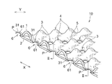
以下本発明を、その好ましい実施形態に基づき図面を参照しながら説明する。図1〜図2には、本発明の立体シートの一実施形態が示されている。図1は、立体シートの要部を一部断面により模式的に示す斜視図であり、図2は、図1に示すII−II線断面図である。本実施形態の立体シート10は、互いに積層された第1不織布1及び第2不織布2が部分的に熱融着されてシート形成用融着部3が形成され、第1不織布1が、シート形成用融着部3で囲まれた非融着部において第2不織布2から離れる方向に突出して、内部が中空の凸部4を多数形成している立体シートである。第1不織布1と第2不織布2とは部分的に熱融着されており、それにより多数のシート形成用融着部3が形成されている。第1不織布1は、シート形成用融着部3以外の部分において、第2不織布2側とは反対向きに突出して、内部空洞の多数の凸部4を形成している。このように、立体シート10は、第2不織布2側の面がほぼ平坦であり、第1不織布1側に起伏の大きな凹凸が形成されている。第1不織布1側の凸部4は、立体シート10を、例えば、吸収性物品の表面シートとして用いたときに、着用者の肌側に向く方向に突出する方向に配置する。
The present invention will be described below based on preferred embodiments with reference to the drawings. 1 to 2 show an embodiment of a three-dimensional sheet of the present invention. FIG. 1 is a perspective view schematically showing a main part of a three-dimensional sheet with a partial cross section, and FIG. 2 is a cross-sectional view taken along the line II-II shown in FIG. In the three-
立体シート10は、長手方向X及びこれと直交する幅方向Yを有している。本実施形態の立体シート10においては、立体シート10の長手方向Xが、第1シート基材11及び第2シート基材12の構成繊維の主な配向方向を見て、該繊維の配向方向に沿うMD方向に一致しており、立体シート10の幅方向Yが、MD方向に直交するCD方向に一致している。また、MD方向(X方向)は、立体シート10を製造するときの搬送方向でもある。
The three-
非融着部である凸部4は、周囲を、相互に離間した複数のシート形成用融着部3によって囲まれており、図1に示す立体シート10においては、4個のシート形成用融着部3によって周囲を囲まれている。尚、凸部4を囲むシート形成用融着部3の数は、4個に限られず、例えば、2個、3個、5個、6個、或いは7個以上とすることもできる。凸部4を囲むシート形成用融着部3の数は、好ましくは4個以上であり、更に好ましくは5個以上であり、また、より好ましくは8個以下であり、更に好ましくは6個以下である。
The
凸部4の配置について、詳述すると、凸部4は、図1に示すように、長手方向Xに、一定の間隔を空けて一列をなすように配置されており、このような列が幅方向Yに、多列に形成されている。また、凸部4は、幅方向Yにも、一定の間隔を空けて一列をなすように配置されており、このような列が長手方向Xに、多列に形成されている。本実施形態の立体シート10においては、長手方向Xに延びる一つの列に着目すると、該列を構成する凸部4と、該列に幅方向Yに隣り合う別の列を構成する凸部4とが、半ピッチずれて配されている。また、幅手方向Yに延びる一つの列に着目すると、該列を構成する凸部4と、該列に長手方向Xに隣り合う別の列を構成する凸部4とが、半ピッチずれて配されている。
The arrangement of the
内部が中空の各凸部4は、それぞれが別個に独立して存在しているのではなく、任意の一つの凸部4に着目したとき、該凸部4の全周囲にて隣接する凸部4と連結している。凸部4どうしの連結部5の高さは、凸部4の頂部の高さよりも低くなっている。しかし、連結部5の頂部は、シート形成用融着部3よりは高い位置にある。一方、シート形成用融着部3は、立体シート10の凹凸構造の各凹部の中心に位置しており、各凹部は、それぞれが別個に独立して存在している。
The
各凸部4の断面形状としては、全体として稜線が滑らかに丸みを帯びた、ドーム状の形状、扁平な直方体、或いは截頭四角錐体等であることが好ましく、本実施形態の立体シート10においては、図1に示すように、丸みを帯びたドーム状の形状となっている。
The cross-sectional shape of each
各シート形成用融着部3を平面視した形状としては、円形状、矩形状、トラック形状、正多角形状等であることが好ましく、本実施形態の立体シート10においては、図1に示すように、円形状となっている。
The shape of each sheet-forming
立体シート10においては、シート形成用融着部3は、図1,図2に示すように、その輪郭31よりも内側に、該輪郭31の形状に相似する形状の外周縁61を有する貫通孔6を備えている。各貫通孔6は、各シート形成用融着部3の内側に1個、第1不織布1及び第2不織布2を貫通して形成されている。各貫通孔6を平面視した形状としては、シート形成用融着部3の形状を一様に縮小した相似形状であり、本実施形態の立体シート10においては、図1に示すように、円形状となっている。
In the three-
立体シート10は、シート形成用融着部3の内側に貫通孔6を備えているので、図2に示すように、立体シート10においては、シート形成用融着部3における輪郭31と貫通孔6の外周縁61との間の部分Pで、第1不織布1及び第2不織布2が接合されている。前記部分Pにおける貫通孔6の外周縁61側の内縁部Qには、断面視して、後述する第1不織布1及び第2不織布2を構成する長繊維の繊維形状が存在していない状態となっている。具体的には、前記部分Pは、図2に示すように、シート形成用融着部3の輪郭31と貫通孔6の外周縁61との間の幅のある部分であり環状に形成されている。このような環状の前記部分Pは、貫通孔6の外周縁61側の内縁部Qと、シート形成用融着部3の輪郭31側の外縁部Rとを有している。そして、前記部分Pにおける内縁部Qにおいては、長繊維が均一に溶融し、もはや繊維形状が存在せずフィルム化した状態となっている。また、前記部分Pにおける外縁部Rにおいては、断面視して、第1不織布1及び第2不織布2を構成する長繊維の繊維形状が存在する状態、すなわち完全にはフィルム化していない状態になっている。環状の前記部分Pのフィルム化の程度は、内縁部Q側から外縁部R側に向かって、同心円状に離れた部位ほど、その程度は小さくなる。すなわち、環状の前記部分Pは、断面視して、第1不織布1及び第2不織布2を構成する長繊維の繊維間距離が、内縁部Q側から外縁部R側に向かって、漸次広くなっており、グラデーション的な構造を形成している。グラデーション的な構造を形成しているか否かは次の方法で判断する。立体シート10のサンプルを液体窒素に浸漬し、十分に凍結させる。また市販のカミソリを同様に液体窒素に十分に浸漬する。外縁部R近傍の部位、及び内縁部Q近傍の部位を、前記カミソリを用いて厚み方向に沿って切断する。その際、切断面の形状がカミソリによる切断の影響を受けなくすことを目的で、カミソリの刃と反対面をハンマー等で叩き、瞬時に切断する。切断面を電子顕微鏡で観察し、それらの部位の厚みを測定する。内縁部Q近傍の厚みと、外縁部R近傍の厚みを比べ、外縁部R近傍の厚み>内縁部Q近傍の厚みとなっていた場合、「グラデーション的な構造を形成している」と判断する。
Since the three-
第1不織布1及び第2不織布2は、長繊維からなるウェブを熱融着部により固定した不織布であり、該不織布としては、スパンボンド不織布、メルトブローン不織布、又はスパンボンドの層とメルトブローンの層との積層不織布等が用いられる。
The 1st
第1不織布1及び第2不織布2を構成する長繊維は、溶融した熱可塑性樹脂を均一に紡糸して形成された単層繊維である。ここで、「単層繊維」とは、同芯型若しくは偏芯型の芯鞘型の繊維、又はサイド・バイ・サイド型の繊維を含まず、紡糸して形成された繊維が均一な一層構造の繊維であることを意味する。上記長繊維の繊維径は、好ましくは0.5dtex以上、更に好ましくは0.8dtex以上であり、5.0dtex以下、特に好ましくは4.0dtex以下である。
The long fibers constituting the first
第1不織布1及び第2不織布2を構成する熱可塑性樹脂としては、ポリオレフィン系樹脂、ポリエステル系樹脂、ポリアミド系樹脂、アクリロニトリル系樹脂、ビニル系樹脂、ビニリデン系樹脂などが挙げられる。ポリオレフィン系樹脂としてはポリエチレン、ポリプロピレン、ポリブデン等が挙げられる。ポリエステル系樹脂としてはポリエチレンテレフタレート、ポリブチレンテレフタレート等が挙げられる。ポリアミド系樹脂としてはナイロン等が挙げられる。ビニル系樹脂としてはポリ塩化ビニル等が挙げられる。ビニリデン系樹脂としてはポリ塩化ビニリデン等が挙げられる。また、これら各種樹脂の1種を単独で又は2種以上を混合して用いることもでき、これら各種樹脂の変成物を用いることもできる。更に、これら各種樹脂としては、ホモポリマー、ランダムコポリマー、ブロックコポリマーの何れか1種以上を50〜100質量%含んだ樹脂であることが好ましい。また、これらホモポリマー、ランダムコポリマー、或いはブロックコポリマーを混合した樹脂でもよい。尚、第1不織布1と第2不織布2との剥離強度向上の観点からは、第1不織布1及び第2不織布2は、構成する熱可塑性樹脂が同一であることが好ましい。
Examples of the thermoplastic resin constituting the first
更に、第1不織布1と第2不織布2との剥離強度が実使用に耐え得る強度を得る観点からは、第1不織布1及び第2不織布2を構成する熱可塑性樹脂が、単一樹脂であることが好ましい。ここで、単一樹脂としては、ホモポリマーからなるポリエチレン樹脂、ホモポリマーからなるポリプロピレン樹脂、或いはホモポリマーからなるポリエチレンテレフタレート樹脂等が挙げられ、紡糸性の観点から、ホモポリマーからなるポリプロピレン樹脂が好ましい。上記観点は、本発明者が、第1不織布1及び第2不織布2を構成する熱可塑性樹脂が同一の単一樹脂であれば、第1不織布1と第2不織布2との剥離強度が、シール面積によらずに一定の強度が得られることを見出したことにより証明される。
Furthermore, from the viewpoint of obtaining strength at which the peel strength between the first
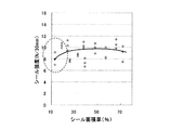
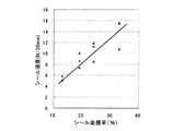
図3には、同一の単一樹脂の熱可塑性樹脂から構成された第1不織布1及び第2不織布2を部分的に融着させた場合のシール強度とシール面積率との関係がプロットされている。具体的には、図4(a)に示すように、長手方向Xに200mm幅方向Yに50mmの第1不織布1及び第2不織布2を用意し、それらを重ね合わせ、重ね合わせたサンプルの中央部Cに、長手方向Xに30mm、シール幅2mmの熱融着シール線32を幅方向Yに一定の間隔(ピッチ)を空けて複数本配して接着(シール)し、測定サンプルSを作製する。このような測定サンプルSを、熱融着シール線の幅方向Yの間隔(ピッチ)を種々変更して作製し、シール面積率の異なる測定サンプルを複数個作製する。次いで、図4(b)に示すように、作製された各測定サンプルSの接着(シール)強度を、X方向が引張方向となるように、引張試験機(例えば、オリエンテック社製テンシロン引張り試験機「RTA−100」)のチャック(チャック間10mm)に取り付け、引張速度300mm/minで引っ張り、測定サンプル破断までの最大荷重点(シール強度)を測定する。このようにして測定されたシール強度とシール面積率との関係をプロットしたものが図3である。また、図5には、ポリエチレンテレフタレート樹脂とポリエチレン樹脂から構成された芯鞘構造の長繊維から構成された第1不織布及び第2不織布を部分的に融着させた場合のシール強度とシール面積率との関係がプロットされている。尚、図5の測定には、図3と同様に測定サンプルを作製してシール強度を測定している。
FIG. 3 plots the relationship between the seal strength and the seal area ratio when the first
一般的には、図5に示すように、シール面積率の増加と共にシール強度も増加する。このような現象が起こる原因について考察する。芯鞘構造を有する不織布に熱融着(シール)を施すと、融着(シール)された部位においてフィルム化が生じるが、その断面には芯を形成する高融点の繊維がその繊維形状を維持したまま存在するため、融着(シール)部を構成する、それぞれの第1不織布及び第2不織布は、融着(シール)部において熱によるダメージが小さく、図4に示す剥離を行った際、第1不織布と第2不織布の境界面にて剥離が生じ、その結果、シール面積に比例して剥離強度が増大するものと思われる。しかしながら、本発明者は、図3に示すように、同一の単一樹脂の熱可塑性樹脂から構成された第1不織布1及び第2不織布2を融着させた場合は、図3に示すように、シール強度がシール面積率によらず略一定となることを見出した。このような現象が起こる原因について考察すると、同一の単一樹脂からなる繊維であるが故に、融着(シール)部において、もはや繊維構造を保つことが不可能と思われ、融着(シール)部を構成する第1不織布及び第2不織布は、融着(シール)部において熱による影響を大きく受けると考えられる。一般的にこのように熱による影響を大きく受けると、図4に示す剥離を行うと、ダメージを受けていたシール部が直ぐに損壊し、シール強度は発現しない(極めて弱くなる)と思われるが、本発明者は、融着(シール)部である、シート形成用融着部3の輪郭31と貫通孔6の外周縁61との間の前記部分Pのように、幅のある部分の場合、シート形成用融着部3の輪郭31側の外縁部R側には、融着(シール)時に熱の影響を受けた弱融着部が形成され、貫通孔6の外周縁61側の内縁部Q側には、長繊維が溶融して繊維形状が存在しないフィルム化した融着部が形成されていることを見出した。また、本発明者は、外縁部R側の弱融着部においては、長繊維の繊維形状が消失することなく繊維どうしが部分的に融着しており、剥離の際には、まず該部位を起点として前記部分Pの融着自体の破壊が生じ、それに引き続き、第1不織布及び第2不織布の破壊が生じることを見出した。よって、単一樹脂の熱可塑性樹脂から構成された第1不織布1及び第2不織布2を融着させた場合の剥離強度は、その融着(シール)部の剥離強度ではなく、融着(シール)部を構成するそれぞれの不織布の破断強度相当となるため、シール面積によらず、その強度は略一定になったと考えられる。
従って、第1不織布1及び第2不織布2を構成する熱可塑性樹脂が、同一の単一樹脂であれば、シール面積によらずに一定の強度が得られ、シート形成用融着部3の輪郭31と貫通孔6の外周縁61との間の部分Pだけで第1不織布1及び第2不織布2が接合されていたとしても、実使用に耐え得る、第1不織布1及び第2不織布2の剥離強度が得られることが推測される。以上のことから、第1不織布1及び第2不織布2として、単一樹脂であるホモポリマーからなるポリプロピレン樹脂を用いて形成されたスパンボンド不織布を使用することが最も好ましい。
In general, as shown in FIG. 5, the seal strength increases with an increase in the seal area ratio. Consider the cause of this phenomenon. When a non-woven fabric having a core-sheath structure is heat-sealed (sealed), a film is formed at the fused (sealed) portion, but the high melting point fibers forming the core maintain its fiber shape in the cross section. Therefore, each of the first nonwoven fabric and the second nonwoven fabric constituting the fusion (seal) part is less damaged by heat in the fusion (seal) part, and when peeling shown in FIG. It is considered that peeling occurs at the interface between the first nonwoven fabric and the second nonwoven fabric, and as a result, the peeling strength increases in proportion to the seal area. However, as shown in FIG. 3, the present inventor fused the first
Therefore, if the thermoplastic resin which comprises the 1st
次に、本実施形態の立体シート10の製造方法を図6,図7を参照しながら説明する。
立体シート10の製造方法は、周面が凹凸形状となっている第1ロール11と第1ロールの凹凸形状と噛み合い形状となっている凹凸形状を周面に有する第2ロール12との噛み合わせ部に噛み込ませて第1不織布1を凹凸賦形する賦形工程と、該賦形工程の後、第2不織布2を、第1ロール11における凸部11a上に位置する第1不織布1と、第1ヒートロール13及び第2ヒートロール14により接合してシート形成用融着部3を形成して該シート形成用融着部3内に貫通孔6を形成する融着開孔工程とを備えている。第1ロール11に対して、第2ロール12、第1ヒートロール13及び第2ヒートロール14は、対向配置されており、第1ロール11の回転方向Rの上流側から下流側に向かって第1ロール11の周面に対して、その順に配置されている。周面が凹凸形状となっている第1ロール11及び第2ロール12に関しては、例えば、本出願人の先願の特開2004−174234号公報に記載のもの等を用いることができる。第1ヒートロール13及び第2ヒートロール14は、それぞれ周面に凹凸を有していないフラットなアンビルロールである。
Next, the manufacturing method of the three-
The manufacturing method of the three-
まず、第1不織布1の原反(不図示)から第1不織布1を繰り出す。また、これとは別に、第2不織布2の原反(不図示)から第2不織布2を繰り出す。そして、図6に示すように、繰り出された第1不織布1を、第1ロールと第2ロール12との噛み合わせ部に噛み込ませて第1不織布1を凹凸賦形する。
First, the first
次いで、図6に示すように、第1不織布1を第1ロール11の周面に引き続き吸引保持した状態下に、第2不織布2を重ね合わせ、その重ね合わせたものを、第1ロール11と周面平滑な第1ヒートロール13との間で挟圧する。このとき、第1ロール11と第1ヒートロール13の両方又は第1ヒートロール13のみを所定温度に加熱しておく。これによって、第1ロール11における凸部11a上に、つまり各歯車の歯の上に位置する第1不織布1と第2不織布2とを熱融着によって接合してシート形成用融着部3を形成する。
Next, as shown in FIG. 6, the second
次いで、図6,図7に示すように、熱融着によって接合された第1不織布1及び第2不織布2の重ね合わせたものを、第1ロール11の周面に引き続き吸引保持した状態下で移動させ、該重ね合わせたものを、第1ロール11と周面平滑な第2ヒートロール14との間で挟圧する。このとき、第1ロール11と第2ヒートロール14の両方又は第2ヒートロール14のみを所定温度に加熱しておく。これによって、第1ロール11における凸部11a上に、つまり各歯車の歯の上に位置するシート形成用融着部3において、更に第1不織布1及び第2不織布2を構成していた熱可塑性樹脂を溶融し、溶融した樹脂が該凸部11aの周囲に移動して貫通孔6を形成する。具体的には、溶融した樹脂が、該凸部11aの中心から外方に向かって同心円状に徐々に離れた部位に移動して、シート形成用融着部3の内に貫通孔6を形成する。その際、シート形成用融着部3の輪郭31と貫通孔6の外周縁61との間の幅のある環状の部分Pにおいては、外周縁61側の内縁部Qが、構成繊維の繊維形状が存在しないフィルム化した状態となり、輪郭31側の外縁部Rが、構成繊維の繊維形状が存在する状態、すなわち完全にはフィルム化していない状態となる。このようにしてシート形成用融着部3内に貫通孔6が形成されるので、シート形成用融着部3の輪郭31と貫通孔6の外周縁61との間の部分Pだけで第1不織布1及び第2不織布2が接合されている立体シート10が連続的に製造される。
Next, as shown in FIG. 6 and FIG. 7, the first
上述した本実施形態の立体シート10は、第1不織布1側が着用者の肌側を向くようにして、使い捨ておむつ、生理用ナプキン、パンティライナー(おりものシート)、失禁パッド等の吸収性物品の表面シートとして用いられるものである。すなわち、第1不織布1は、立体シート10を、吸収性物品の表面シートとして用いたときに、着用者の肌側に向けられる面(肌対向面)を形成するようになり、第2不織布2は、前記吸収性物品を構成する収体体側に向けられる面(非肌対向面)を形成するようになる。
The three-
本実施形態の立体シート10を吸収性物品の表面シートとして使用した際の作用効果について説明する。
本実施形態の立体シート10は、図1に示すように、互いに積層された第1不織布1及び第2不織布2が部分的に配されたシート形成用融着部3で接合して形成されているので、単層の立体シートに比べ、吸収性物品の表面シートとして用いたときに、着用時に中空の凸部4が潰れ難くなっている。また、第1不織布1及び第2不織布2を構成する長繊維が、溶融した熱可塑性樹脂を均一に紡糸して形成された単層繊維であるので、シート形成用融着部3における剥離強度が高く、使用時に積層間が剥がれ難くなっている。また、各凸部4により着用時における肌との接触面積が抑えられ、液戻りが低減し、赤みやかぶれを低減することが期待できる。また、軟便の拡がりを抑制し、便の肌への付着を低減することが期待できる。更に、シート形成用融着部3内に貫通孔6が形成されているので、液残りが低減し、液戻りが更に低減し、赤みやかぶれを更に低減することが期待できる。また、軟便の拡がりを更に抑制し、便の肌への付着を更に低減することが期待できる。
The effect at the time of using the
As shown in FIG. 1, the three-
また、本実施形態の立体シート10は、第1不織布1及び第2不織布2を構成する熱可塑性樹脂が同一のものを用いれば、相溶性の向上により剥離強度(シール強度)が向上し、シート形成用融着部3の輪郭31と貫通孔6の外周縁61との間の部分Pだけで第1不織布1及び第2不織布2が接合されているとしても、使用時に積層間が更に剥がれ難くなる。特に、本実施形態の立体シート10においては、前記熱可塑性樹脂が単一樹脂から形成されていれば、貫通孔6が形成され易く、図3に示すように、シール強度がシール面積率によらず略一定となり、実使用に耐え得る、第1不織布1及び第2不織布2の剥離強度が得られ、使用時に積層間が更に一層剥がれ難くなる。具体的には、第1不織布1及び第2不織布2として、単一樹脂であるホモポリマーからなるポリプロピレン樹脂を用いて製造されたスパンボンド不織布を使用すれば、圧力によりシート形成用融着部3に貫通孔6が開孔し易く、液戻りが低減し、赤みやかぶれを低減することが期待できる。
Moreover, if the thermoplastic resin which comprises the 1st
上述した効果が、一層確実に発現されるようにする観点から、立体シート10は、以下の構成を有することが好ましい。
From the viewpoint of ensuring that the above-described effects are more reliably exhibited, the three-
凸部4の高さは、1mm以上20mm以下であることが好ましく、3mm以上15mm以下であることが更に好ましい。
立体シート10の単位面積(1cm2)当たりの凸部4の数は、1個以上15個以下であることが好ましく、3個以上12個以下であることが更に好ましい。
また、立体シート10の単位面積(1cm2)当たりの貫通孔6の数は、1個以上50個以下であることが好ましく、4個以上30個以下であることが更に好ましい。
The height of the
The number of
Further, the number of through
凸部4の底部面積(S1)は、1mm2以上400mm2以下であることが好ましく、4mm2以上300mm2以下であることが更に好ましい。シート形成用融着部3の面積(S2)は、1mm2以上50mm2以下であることが好ましく、1mm2以上36mm2以下であることが更に好ましい。ここで、シート形成用融着部3の面積(S2)とは、シート形成用融着部3の輪郭31で囲まれた領域の面積を意味する。
The bottom area (S1) of the
貫通孔6の開孔面積(S3)は、1mm2以上100mm2以下であることが好ましく、2mm2以上50mm2以下であることが更に好ましい。ここで、貫通孔6の開孔面積(S3)とは。貫通孔6の外周縁61で囲まれた領域の面積を意味する。
The opening area (S3) of the through
貫通孔6の長さは、1mm以上10mm以下であることが好ましく、2mm以上7mm以下であることが更に好ましい。また、シート形成用融着部3の長さは0.1mm以上5mm以下程度であることが好ましい。ここで、「貫通孔6の長さ」とは、貫通孔6の最も広い位置での長さを意味し、「シート形成用融着部3の長さ」とは、シート形成用融着部3の最も広い位置での長さを意味する。
The length of the through
また、環状の前記部分Pの幅(図2におけるX方向の長さ)は、シート形成用融着部3の長さの3%以上20%以下であることが好ましく、5%以上15%以下であることが更に好ましい。具体的には前記部分Pの幅は、0.5mm以上5mm以下程度であることが好ましい。
環状の前記部分Pの幅の確認方法は次のとおりとする。立体シート10を液体窒素に浸漬し、十分に凍結する。また、市販のカミソリを同様に液体窒素に十分に浸漬する。環状の前記部分Pを、冷やしたカミソリを用いて厚み方向に沿って切断する。その際、切断面の形状がカミソリによる切断の影響を受けなくすことを目的で、カミソリの刃と反対面をハンマー等で叩き瞬時に切断する。切断箇所を、100倍程度に拡大した顕微鏡で観察し、繊維の状態が視認できる領域を外縁部Rとし、フィルム状で繊維が視認できない領域を内縁部Qとして判断し、RとQとの距離をもってPの幅とする。
Further, the width of the annular portion P (the length in the X direction in FIG. 2) is preferably 3% or more and 20% or less of the length of the fused
The method for confirming the width of the annular portion P is as follows. The three-
また、立体シート10における第1不織布1と第2不織布2との剥離強度は、0.2N/30mm以上であることが好ましく、0.5N/30mm以上であることが更に好ましい。尚、前記剥離強度の上限値に特に制限はなく、高ければ高いほど好ましいが、上限値として3N/30mm程度であれば、十分に満足すべき効果が得られる。前記剥離強度は、長手方向Xに200mm幅方向Yに30mmに立体シート10をカットしてカットサンプルを作製し、このカットサンプルにおける第1不織布1と第2不織布2との剥離強度を、X方向が引張方向となるように、引張試験機(例えば、オリエンテック社製テンシロン引張り試験機「RTA−100」)のチャック(チャック間10mm)に取り付け、引張速度300mm/minで引っ張り、測定サンプル破断までの最大荷重点(剥離強度)を測定して求める。
The peel strength between the first
また、立体シート10を構成する第2不織布2は、その親水度が、立体シート10を構成する第1不織布1の親水度よりも高いことが好ましい。ここで、「親水度」とは、以下に述べる方法で測定された繊維の接触角に基づき判断される。具体的には、親水度が高いことは接触角が小さいことと同義であり、親水度が低いことは接触角が大きいことと同義である。
Moreover, it is preferable that the 2nd
〔接触角の測定方法〕
立体シート10を構成する第1不織布1又は第2不織布2の所定の部位から繊維を取り出し、その繊維に対する水の接触角を測定する。測定装置として、協和界面科学株式会社製の自動接触角計MCA−Jを用いる。接触角の測定には蒸留水を用いる。インクジェット方式水滴吐出部(クラスターテクノロジー社製、吐出部孔径が25μmのパルスインジェクターCTC−25)から吐出される液量を20ピコリットルに設定して、水滴を、繊維の真上に滴下する。滴下の様子を水平に設置されたカメラに接続された高速度録画装置に録画する。録画装置は後に画像解析や画像解析をする観点から、高速度キャプチャー装置が組み込まれたパーソナルコンピュータが望ましい。本測定では、17msec毎に画像が録画される。録画された映像において、不織布から取り出した繊維に水滴が着滴した最初の画像を、付属ソフトFAMAS(ソフトのバージョンは2.6.2、解析手法は液滴法、解析方法はθ/2法、画像処理アルゴリズムは無反射、画像処理イメージモードはフレーム、スレッシホールドレベルは200、曲率補正はしない、とする)にて画像解析を行い、水滴の空気に触れる面と繊維のなす角を算出し、接触角とする。第1不織布1又は第2不織布2から取り出した繊維は、繊維長1mmに裁断し、該繊維を接触角計のサンプル台に載せて、水平に維持する。該繊維1本につき異なる2箇所の接触角を測定する。N=5本の接触角を小数点以下1桁まで計測し、合計10箇所の測定値を平均した値(小数点以下第2桁で四捨五入)を接触角と定義する。
[Measurement method of contact angle]
A fiber is taken out from a predetermined portion of the first
立体シート10を構成する第2不織布2は、その坪量が、立体シート10を構成する第1不織布1の坪量よりも高いことが好ましい。具体的には、第2不織布2の坪量は、8g/m2以上であることが好ましく、10g/m2以上であることが更に好ましく、そして、25g/m2以下であることが好ましく、20g/m2以下であることが更に好ましく、具体的には、8g/m2以上25g/m2以下であることが好ましく、10g/m2以上20g/m2以下であることが更に好ましい。第1不織布1の坪量は、8g/m2以上であることが好ましく、10g/m2以上であることが更に好ましく、そして、20g/m2以下であることが好ましく、18g/m2以下であることが更に好ましく、具体的には、8g/m2以上20g/m2以下であることが好ましく、10g/m2以上18g/m2以下であることが更に好ましい。
The basis weight of the second
以上、本発明をその好ましい実施形態に基づき説明したが、本発明は前記実施形態に制限されない。例えば上述した立体シート10の製造方法においては、シート形成用融着部3の形成及び貫通孔6の形成を連続的に行っているが、断続的に行ってもよい。
As mentioned above, although this invention was demonstrated based on the preferable embodiment, this invention is not restrict | limited to the said embodiment. For example, in the manufacturing method of the three-
また、上述した立体シート10の製造方法においては、第1ロール11と上流側の第1ヒートロール13とでシート形成用融着部3を形成し、その後、第1ロール11と下流側の第2ヒートロール14とで、貫通孔6を形成しているが、第1ロール11及び上流側の第1ヒートロール13のみで、シート形成用融着部3及び貫通孔6を形成してもよい。具体的には、第1ロール11及び上流側の第1ヒートロール13との挟持圧力と温度等を調整することにより、第1不織布1を第2不織布2に重ね合わせたものに対して、シート形成用融着部3を形成しながら、貫通孔6を形成してもよい。
Moreover, in the manufacturing method of the three-dimensional sheet |
上述した実施形態に関し、更に以下の立体シートを開示する。 The following three-dimensional sheet | seat is further disclosed regarding embodiment mentioned above.
<1>
互いに積層された第1不織布及び第2不織布が部分的に熱融着されてシート形成用融着部が形成され、該第1不織布が、該シート形成用融着部で囲まれた非融着部において該第2不織布から離れる方向に突出して、内部が中空の凸部を多数形成している立体シートであって、
前記第1不織布及び前記第2不織布は、長繊維からなるウェブを熱融着部により固定した不織布であり、
前記長繊維は、溶融した熱可塑性樹脂を均一に紡糸して形成された単層繊維であり、
前記シート形成用融着部は、その輪郭よりも内側に、該輪郭の形状に相似する形状の外周縁を有する貫通孔を備え、該シート形成用融着部における前記輪郭と該貫通孔の外周縁との間の部分で、前記第1不織布及び前記第2不織布が接合されている立体シート。
<1>
The first nonwoven fabric and the second nonwoven fabric laminated together are partially heat-sealed to form a sheet-forming fused portion, and the first nonwoven fabric is surrounded by the sheet-forming fused portion. Projecting in a direction away from the second non-woven fabric in the part, and a solid sheet in which a large number of hollow convex portions are formed,
The first nonwoven fabric and the second nonwoven fabric are nonwoven fabrics in which a web composed of long fibers is fixed by a heat-sealing part,
The long fiber is a single-layer fiber formed by uniformly spinning a molten thermoplastic resin,
The sheet forming fusion part includes a through hole having an outer peripheral edge having a shape similar to the shape of the outline on the inner side of the outline, and the outline and the outside of the through hole in the sheet forming fusion part. A three-dimensional sheet in which the first nonwoven fabric and the second nonwoven fabric are joined at a portion between the periphery.
<2>
前記第1不織布及び前記第2不織布は、構成する前記熱可塑性樹脂が同一である前記<1>に記載の立体シート。
<3>
前記熱可塑性樹脂は、単一樹脂からなる前記<1>又は<2>に記載の立体シート。
<4>
前記第1不織布と前記第2不織布との剥離強度は、0.2N/30mm以上である前記<1>〜<3>の何れか1に記載の立体シート。
<5>
前記シート形成用融着部の輪郭と前記貫通孔の外周縁との間の部分における該外周縁側の内縁部には、断面視して前記長繊維の繊維形状が存在していない前記<1>〜<4>の何れか1に記載の立体シート。
<6>
前記第2不織布は、その親水度が、前記第1不織布の親水度よりも高い前記<1>〜<5>の何れか1に記載の立体シート。
<7>
前記第2不織布は、その坪量が、前記第1不織布の坪量よりも高く、該第1不織布の坪量は、8g/m2以上である前記<1>〜<6>の何れか1に記載の立体シート。
<8>
前記立体シートは、前記第2不織布側の面がほぼ平坦であり、前記第1不織布側に起伏の大きな凹凸が形成されている前記<1>〜<7>の何れか1に記載の立体シート。
<2>
The said 1st nonwoven fabric and the said 2nd nonwoven fabric are the three-dimensional sheets as described in said <1> whose said thermoplastic resin to comprise is the same.
<3>
The three-dimensional sheet according to <1> or <2>, wherein the thermoplastic resin is a single resin.
<4>
The three-dimensional sheet according to any one of <1> to <3>, wherein the peel strength between the first nonwoven fabric and the second nonwoven fabric is 0.2 N / 30 mm or more.
<5>
<1> in which the fiber shape of the long fibers does not exist in the inner edge portion on the outer peripheral edge side in the portion between the outline of the fusion forming portion for sheet formation and the outer peripheral edge of the through hole. The solid sheet according to any one of ~ <4>.
<6>
The said 2nd nonwoven fabric is a solid sheet of any one of said <1>-<5> whose hydrophilicity is higher than the hydrophilicity of a said 1st nonwoven fabric.
<7>
The basis weight of the second nonwoven fabric is higher than the basis weight of the first nonwoven fabric, and the basis weight of the first nonwoven fabric is any one of <1> to <6> above 8 g / m 2 or more. The solid sheet as described in 1.
<8>
The three-dimensional sheet according to any one of the above items <1> to <7>, wherein the surface of the second nonwoven fabric side is substantially flat, and irregularities having large undulations are formed on the first nonwoven fabric side. .
<9>
前記非融着部である前記凸部は、周囲を、相互に離間した複数の前記シート形成用融着部によって囲まれており、前記凸部を囲む前記シート形成用融着部の数は、4個以上であり、好ましくは5個以上であり、また、8個以下であり、好ましくは6個以下である前記<1>〜<8>の何れか1に記載の立体シート。
<10>
前記凸部は、長手方向Xに、一定の間隔を空けて一列をなすように配置されており、このような列が幅方向Yに、多列に形成されており、前記凸部は、幅方向Yにも、一定の間隔を空けて一列をなすように配置されており、このような列が長手方向Xに、多列に形成されており、長手方向Xに延びる一つの列に着目すると、該列を構成する凸部と、該列に幅方向Yに隣り合う別の列を構成する凸部とが、半ピッチずれて配されており、幅手方向Yに延びる一つの列に着目すると、該列を構成する凸部と、該列に長手方向Xに隣り合う別の列を構成する凸部とが、半ピッチずれて配されている前記<1>〜<9>の何れか1に記載の立体シート。
<11>
内部が中空の前記各凸部は、それぞれが別個に独立して存在しているのではなく、任意の一つの凸部に着目したとき、該凸部の全周囲にて隣接する凸部と連結しており、凸部どうしの連結部の高さは、凸部の頂部の高さよりも低くなっており、前記連結部の頂部は、前記シート形成用融着部より高い位置にあり、該シート形成用融着部は、前記立体シートの凹凸構造の各凹部の中心に位置しており、該凹部は、それぞれが別個に独立して存在している前記<1>〜<10>の何れか1に記載の立体シート。
<12>
前記凸部の断面形状としては、全体として稜線が滑らかに丸みを帯びた、ドーム状の形状、扁平な直方体、或いは截頭四角錐体の何れかであり、前記シート形成用融着部を平面視した形状としては、円形状、矩形状、トラック形状の何れかである前記<1>〜<11>の何れか1に記載の立体シート。
<13>
前記シート形成用融着部における前記貫通孔は、該シート形成用融着部の内側に1個、前記第1不織布及び前記第2不織布を貫通して形成されており、該貫通孔を平面視した形状としては、該シート形成用融着部の形状を一様に縮小した相似形状であり円形状である前記<1>〜<12>の何れか1に記載立体シート。
<14>
前記立体シートにおいては、前記シート形成用融着部における輪郭と前記貫通孔の外周縁との間の部分Pで、前記第1不織布及び前記第2不織布が接合されており、前記部分Pのうち、前記貫通孔の外周縁側の内縁部Qにおいては、断面視して、前記第1不織布及び前記第2不織布を構成する長繊維の繊維形状が存在していない状態となっており、前記部分Pにおける内縁部Qにおいては、繊維形状が存在せずフィルム化した状態となっており、前記部分Pのうち、前記貫通孔から離れた部位Rにおいては、断面視して、前記第1不織布及び前記第2不織布を構成する長繊維の繊維形状が存在し、完全にはフィルム化していない状態であり、該部分Pのフィルム化の程度は、前記貫通孔の中心から、同心円状に離れた部位ほど、その程度は小さくなる前記<1>〜<13>の何れか1に記載の立体シート。
<15>
前記シート形成用融着部における輪郭と前記貫通孔の外周縁との間の前記部分Pは、該部分Pを厚み方向に沿って断面視したとき、第1不織布1及び第2不織布を構成する長繊維の繊維間距離が、内縁部Q側から外縁部R側に向かって漸次広くなっており、グラデーション的な構造を形成している前記<1>〜<14>の何れか1に記載の立体シート。
<16>
前記内縁部Q近傍の厚みと、前記外縁部R近傍の厚みを比べたとき、該外縁部R近傍の厚み>該内縁部Q近傍の厚みとなっている前記<1>〜<15>の何れか1に記載の立体シート。
<17>
前記第1不織布及び前記第2不織布は、長繊維からなるウェブを熱融着部により固定した不織布であり、該不織布としては、スパンボンド不織布、メルトブローン不織布、又はスパンボンドの層とメルトブローンの層との積層不織布の何れかである前記<1>〜<16>の何れか1に記載の立体シート。
<18>
前記第1不織布及び前記第2不織布を構成する長繊維は、溶融した熱可塑性樹脂を均一に紡糸して形成された単層繊維であり、該単層繊維は、同芯型若しくは偏芯型の芯鞘型の繊維、又はサイド・バイ・サイド型の繊維を含まず、紡糸して形成された繊維が均一な一層構造の繊維である前記<1>〜<17>の何れか1に記載の立体シート。
<19>
前記第1不織布及び前記第2不織布を構成する熱可塑性樹脂としては、ポリオレフィン系樹脂、ポリエステル系樹脂、ポリアミド系樹脂、アクリロニトリル系樹脂、ビニル系樹脂、ビニリデン系樹脂の何れかであり、ポリオレフィン系樹脂としてはポリエチレン、ポリプロピレン、ポリブデンの何れかであり、ポリエステル系樹脂としてはポリエチレンテレフタレート、ポリブチレンテレフタレート何れかであり、ポリアミド系樹脂としてはナイロンであり、ビニル系樹脂としてはポリ塩化ビニルであり、ビニリデン系樹脂としてはポリ塩化ビニリデンであり、これら各種樹脂の1種を単独で又は2種以上を混合して用い、更に、これら各種樹脂は、ホモポリマー、ランダムコポリマー、ブロックコポリマーの何れか1種以上を50〜100質量%含んだ樹脂か、これらホモポリマー、ランダムコポリマー、或いはブロックコポリマーを混合した樹脂である前記<1>〜<18>の何れか1に記載の立体シート。
<20>
前記第1不織布及び前記第2不織布は、長繊維からなるウェブを熱融着部により固定したスパンボンド不織布であり、前記第1不織布及び前記第2不織布2を構成する熱可塑性樹脂はホモポリマーからなるポリプロピレン樹脂である前記<1>〜<19>の何れか1に記載の立体シート。
<21>
前記凸部の高さは、1mm以上20mm以下であり、好ましくは3mm以上15mm以下であり、前記立体シートの単位面積(1cm2)当たりの前記凸部の数は、1個以上15個以下であり、好ましくは3個以上12個以下であり、前記立体シートの単位面積(1cm2)当たりの前記貫通孔の数は、1個以上50個以下であり、好ましくは4個以上30個以下である前記<1>〜<20>の何れか1に記載の立体シート。
<22>
前記凸部の底部面積(S1)は、1mm2以上400mm2以下であり、好ましくは4mm2以上300mm2以下であり、前記シート形成用融着部の面積(S2)は、1mm2以上50mm2以下であり、好ましくは1mm2以上36mm2以下である前記<1>〜<21>の何れか1に記載の立体シート。
<23>
前記貫通孔6の開孔面積(S3)は、1mm2以上100mm2以下であり、好ましくは2mm2以上50mm2以下であり、前記貫通孔6の長さは、1mm以上10mm以下であり、2mm以上7mm以下であり、また、シート形成用融着部3の長さは0.1mm以上5mm以下である前記<1>〜<22>の何れか1に記載の立体シート。
<24>
前記立体シートにおける前記第1不織布と前記第2不織布との剥離強度は、0.2N/30mm以上であり、好ましくは0.5N/30mm以上であり、上限値は3N/30mmである前記<1>〜<23>の何れか1に記載の立体シート。
<25>
前記立体シートを構成する前記第2不織布は、その坪量が、該立体シートを構成する前記第1不織布の坪量よりも高く、
前記第2不織布の坪量は、8g/m2以上であり、好ましくは、10g/m2以上であり、そして、25g/m2以下であり、好ましくは、20g/m2以下であり、好ましくは8g/m2以上25g/m2以下であり、更に好ましくは、10g/m2以上20g/m2以下であり、
前記第1不織布の坪量は、8g/m2以上であり、好ましくは、10g/m2以上であり、そして、20g/m2以下であり、18g/m2以下であることが好ましく、8g/m2以上20g/m2以下であることが好ましく、10g/m2以上18g/m2以下であることが更に好ましい前記<1>〜<24>の何れか1に記載の立体シート。
<9>
The convex portion which is the non-fused portion is surrounded by a plurality of the sheet forming fused portions spaced apart from each other, and the number of the sheet forming fused portions surrounding the convex portion is: The three-dimensional sheet according to any one of <1> to <8>, which is 4 or more, preferably 5 or more, and 8 or less, preferably 6 or less.
<10>
The convex portions are arranged in a row at a certain interval in the longitudinal direction X, and such rows are formed in multiple rows in the width direction Y, and the convex portions have a width of In the direction Y, it is arranged so as to form a line at a certain interval. When such a line is formed in multiple lines in the longitudinal direction X, attention is paid to one line extending in the longitudinal direction X. The convex portion constituting the row and the convex portion constituting another row adjacent to the row in the width direction Y are arranged with a half-pitch shift, and attention is paid to one row extending in the width direction Y. Then, any one of the above items <1> to <9>, wherein the convex portions constituting the row and the convex portions constituting another row adjacent to the row in the longitudinal direction X are arranged with a half-pitch shift. 3. The three-dimensional sheet according to 1.
<11>
Each of the convex portions that are hollow inside does not exist independently independently of each other, but when attention is paid to any one convex portion, it is connected to adjacent convex portions around the entire convex portion. The height of the connecting part between the convex parts is lower than the height of the top part of the convex part, and the top part of the connecting part is at a position higher than the fused part for forming the sheet, The forming fusion part is located at the center of each concave part of the concave-convex structure of the three-dimensional sheet, and the concave part is any one of the above <1> to <10> 3. The three-dimensional sheet according to 1.
<12>
The cross-sectional shape of the convex portion is one of a dome-like shape, a flat rectangular parallelepiped shape, and a truncated quadrangular pyramid with a smoothly rounded ridgeline as a whole, and the fused portion for sheet formation is planar The three-dimensional sheet according to any one of <1> to <11>, wherein the viewed shape is any one of a circular shape, a rectangular shape, and a track shape.
<13>
One through hole in the fused portion for forming the sheet is formed inside the fused portion for forming the sheet so as to penetrate the first nonwoven fabric and the second nonwoven fabric, and the through hole is viewed in plan view. The three-dimensional sheet according to any one of the above items <1> to <12>, which is a similar shape obtained by uniformly reducing the shape of the fused portion for forming the sheet and a circular shape.
<14>
In the three-dimensional sheet, the first non-woven fabric and the second non-woven fabric are joined at a portion P between the contour of the fused portion for forming the sheet and the outer peripheral edge of the through-hole, In the inner edge portion Q on the outer peripheral edge side of the through hole, the fiber shape of the long fibers constituting the first nonwoven fabric and the second nonwoven fabric does not exist in a sectional view, and the portion P In the inner edge portion Q, the fiber shape does not exist and is in a filmed state, and in the portion R away from the through hole in the portion P, the first nonwoven fabric and the portion There is a fiber shape of the long fibers constituting the second nonwoven fabric, and it is in a state where it is not completely formed into a film, and the degree of film formation of the portion P is as far as a concentric circle from the center of the through hole. The degree is small Kunar wherein <1> bulky sheet according to any one of the - <13>.
<15>
The said part P between the outline in the said sheet | seat formation fusion | fusion part and the outer periphery of the said through-hole comprises the 1st
<16>
Any one of the above items <1> to <15>, where the thickness in the vicinity of the inner edge Q is compared with the thickness in the vicinity of the outer edge R, and the thickness in the vicinity of the outer edge R> the thickness in the vicinity of the inner edge Q. The three-dimensional sheet according to
<17>
The first nonwoven fabric and the second nonwoven fabric are nonwoven fabrics in which a web composed of long fibers is fixed by a heat-sealing portion. The three-dimensional sheet according to any one of <1> to <16>, which is any one of the laminated nonwoven fabrics.
<18>
The long fibers constituting the first nonwoven fabric and the second nonwoven fabric are single-layer fibers formed by uniformly spinning a molten thermoplastic resin, and the single-layer fibers are concentric or eccentric. <1> to <17>, wherein the core-sheath fiber or the side-by-side fiber is not included, and the fiber formed by spinning is a uniform single-layer fiber. Three-dimensional sheet.
<19>
The thermoplastic resin constituting the first nonwoven fabric and the second nonwoven fabric is any one of polyolefin resin, polyester resin, polyamide resin, acrylonitrile resin, vinyl resin, vinylidene resin, and polyolefin resin. As the polyester resin, either polyethylene terephthalate or polybutylene terephthalate is used, the polyamide resin is nylon, the vinyl resin is polyvinyl chloride, and vinylidene. Polyvinylidene chloride is used as a resin, and one of these various resins is used alone or in combination of two or more. Further, these various resins are one or more of homopolymers, random copolymers, and block copolymers. 50-100 Or amount% resin containing these homopolymers, random copolymers, or the a resin mixed with a block copolymer <1> bulky sheet according to any one of the - <18>.
<20>
The first nonwoven fabric and the second nonwoven fabric are spunbond nonwoven fabrics in which a web composed of long fibers is fixed by a heat-sealing portion, and the thermoplastic resin constituting the first nonwoven fabric and the second
<21>
The height of the protrusions is 1 mm or more and 20 mm or less, preferably 3 mm or more and 15 mm or less, and the number of the protrusions per unit area (1 cm 2 ) of the three-dimensional sheet is 1 or more and 15 or less. Yes, preferably 3 or more and 12 or less, and the number of the through holes per unit area (1 cm 2 ) of the three-dimensional sheet is 1 or more and 50 or less, preferably 4 or more and 30 or less. The three-dimensional sheet according to any one of <1> to <20>.
<22>
Bottom area of the convex portion (S1) is at 1 mm 2 or more 400 mm 2 or less, preferably 4 mm 2 or more 300 mm 2 or less, the area of the sheet forming fused portion (S2) is 1 mm 2 or more 50 mm 2 The solid sheet according to any one of <1> to <21>, which is 1 mm 2 or more and preferably 36 mm 2 or less.
<23>
The opening area (S3) of the through
<24>
The peel strength between the first nonwoven fabric and the second nonwoven fabric in the three-dimensional sheet is 0.2 N / 30 mm or more, preferably 0.5 N / 30 mm or more, and the upper limit is 3 N / 30 mm <1 The solid sheet according to any one of> to <23>.
<25>
The basis weight of the second nonwoven fabric constituting the three-dimensional sheet is higher than the basis weight of the first nonwoven fabric constituting the three-dimensional sheet,
The basis weight of the second nonwoven fabric is 8 g / m 2 or more, preferably 10 g / m 2 or more, and 25 g / m 2 or less, preferably 20 g / m 2 or less, preferably Is 8 g / m 2 or more and 25 g / m 2 or less, more preferably 10 g / m 2 or more and 20 g / m 2 or less,
The basis weight of the first nonwoven fabric is 8 g / m 2 or more, preferably 10 g / m 2 or more, and 20 g / m 2 or less, preferably 18 g / m 2 or less, 8 g is preferably / m 2 or more 20 g / m 2 or less, the bulky sheet according to any one of the 10 g / m 2 or more 18 g / m 2 or less is still more preferable that the <1> to <24>.
<26>
前記<1>〜<25>の何れか1に記載の立体シートを、前記第1不織布側が着用者の肌側を向くようにして吸収性物品の表面シートとして用いた吸収性物品。
<27>
前記吸収性物品は使い捨ておむつである、前記<26>に記載の吸収性物品。
<28>
前記<1>〜<25>の何れか1に記載の立体シートの製造方法であって、
前記第1不織布の原反から前記第1不織布を繰り出し、これとは別に、前記第2不織布の原反から前記第2不織布を繰り出し、そして、繰り出された該第1不織布を、第1ロールと第2ロールとの噛み合わせ部に噛み込ませて該第1不織布1を凹凸賦形し、次いで、該第1不織布を前記第1ロールの周面に引き続き吸引保持した状態下に、該第2不織布を重ね合わせ、その重ね合わせたものを、第1ロールと周面平滑な第1ヒートロールとの間で挟圧し、このとき該第1ロールと該第1ヒートロールの両方又は該第1ヒートロールのみを加熱しておき、次いで、熱融着によって接合された前記第1不織布及び前記第2不織布の重ね合わせたものを、前記第1ロールの周面に引き続き吸引保持した状態下で移動させ、該重ね合わせたものを、該第1ロールと周面平滑な第2ヒートロールとの間で挟圧し、このときの該第1ロールと該第2ヒートロールの両方又は該第2ヒートロールのみを加熱しておき、該第1ロールにおける凸部上である各歯車の歯の上に位置する前記シート形成用融着部において、更に前記第1不織布及び前記第2不織布を構成していた熱可塑性樹脂を溶融し、溶融した樹脂が該凸部の周囲に移動して前記貫通孔を形成してなる立体シートの製造方法。
<29>
前記第1ロールと上流側の前記第1ヒートロールとで前記シート形成用融着部を形成し、その後、該第1ロールと下流側の前記第2ヒートロールとで、前記貫通孔を形成するか、又は、
前記第1ロール及び上流側の前記第1ヒートロールで、前記シート形成用融着部及び前記貫通孔を形成し、該第1ロール及び上流側の該第1ヒートロールとの挟持圧力と温度等を調整することにより、前記第1不織布を前記第2不織布に重ね合わせたものに対して、該シート形成用融着部を形成しながら、該貫通孔を形成する前記<28>に記載の立体シートの製造方法。
<26>
The absorbent article which used the solid sheet of any one of said <1>-<25> as a surface sheet of an absorbent article so that the said 1st nonwoven fabric side might face a wearer's skin side.
<27>
The absorbent article according to <26>, wherein the absorbent article is a disposable diaper.
<28>
The method for producing a three-dimensional sheet according to any one of <1> to <25>,
The first nonwoven fabric is fed out from the original fabric of the first nonwoven fabric. Separately, the second nonwoven fabric is fed out from the original fabric of the second nonwoven fabric, and the fed first nonwoven fabric is taken as a first roll. The first
<29>
The first roll and the first heat roll on the upstream side form the fused portion for sheet formation, and then the through hole is formed by the first roll and the second heat roll on the downstream side. Or
The sheet-forming fused portion and the through hole are formed by the first roll and the upstream first heat roll, and the sandwiching pressure and temperature between the first roll and the upstream first heat roll, etc. The three-dimensional body as described in <28>, wherein the through hole is formed while the sheet-forming fused portion is formed on the first nonwoven fabric superimposed on the second nonwoven fabric by adjusting Sheet manufacturing method.
以下、実施例により本発明を更に詳細に説明する。しかしながら本発明の範囲はかかる実施例によって何ら制限されるものではない。 Hereinafter, the present invention will be described in more detail with reference to examples. However, the scope of the present invention is not limited by the examples.
[実施例1]
単一樹脂であるポリプロピレン樹脂からなる繊維(2.0dtex)から構成された第1不織布及び第2不織布を、図6に示す製造装置を用いて部分的に熱融着して、図1に示す立体シートを製造した。立体シートの単位面積(1cm2)当たりの凸部の数は3個であり、立体シートの単位面積(1cm2)当たりの貫通孔の数は12個であった。尚、凸部の底部面積(S1)は9mm2であり、シート形成用融着部の面積(S2)5mm2であり、貫通孔の開孔面積(S3)は2mm2であった。また、貫通孔の長さは1mmであり、シート形成用融着部の長さは0.5mmであった。次に上述した測定方法により測定した立体シートの剥離強度は、1.2N/30mmであった。
[Example 1]
1st nonwoven fabric and 2nd nonwoven fabric comprised from the fiber (2.0 dtex) which consists of polypropylene resin which is single resin are partially heat-sealed using the manufacturing apparatus shown in FIG. 6, and it shows in FIG. A three-dimensional sheet was produced. The number of convex portions per unit area (1 cm 2 ) of the three-dimensional sheet was 3, and the number of through holes per unit area (1 cm 2 ) of the three-dimensional sheet was 12. Incidentally, the bottom area of the projection (S1) is 9 mm 2, the area of the sheet forming fused portion (S2) 5 mm 2, opening area of the through-hole (S3) was 2 mm 2. Moreover, the length of the through hole was 1 mm, and the length of the fused part for sheet formation was 0.5 mm. Next, the peel strength of the three-dimensional sheet measured by the measurement method described above was 1.2 N / 30 mm.
[実施例2]
単一樹脂であるポリエチレンテレフタレート樹脂からなる繊維(2.2dtex)から構成された第1不織布及び第2不織布を用いる以外は、実施例1と同様にして実施例2の立体シートを製造した。実施例2の立体シートの剥離強度は、1.0N/30mmであった。
[Example 2]
A three-dimensional sheet of Example 2 was produced in the same manner as Example 1 except that the first nonwoven fabric and the second nonwoven fabric composed of fibers (2.2 dtex) made of polyethylene terephthalate resin, which is a single resin, were used. The peel strength of the three-dimensional sheet of Example 2 was 1.0 N / 30 mm.
[比較例1]
芯部にポリエチレン、鞘部にポリエチレンテレフタレート樹脂を用いた芯鞘複合繊維(2.6dtex、繊維長51mm)から構成された第1不織布及び第2不織布を用いる以外は、実施例1と同様にして比較例1の立体シートを製造した。比較例1の立体シートの剥離強度は、0.13N/30mmであった。
[Comparative Example 1]
Except for using a first nonwoven fabric and a second nonwoven fabric composed of core-sheath composite fibers (2.6 dtex, fiber length 51 mm) using polyethylene for the core and polyethylene terephthalate resin for the sheath, the same as in Example 1 A three-dimensional sheet of Comparative Example 1 was produced. The peel strength of the three-dimensional sheet of Comparative Example 1 was 0.13 N / 30 mm.
〔性能評価〕
花王株式会社製の「メリーズ(登録商標)2013年製」の製品から表面シートを取り除き、実施例1〜2の立体シート又は比較例1の立体シートを替わりに用い、第1不織布側が着用者の肌側を向くようにして使い捨ておむつを作製した。実施例1〜2の立体シート又は比較例1の立体シートを表面シートに用いた使い捨ておむつに関し、以下のようにして装着テストを行い、第1不織布及び第2不織布の剥離の有無を評価した。
<試験条件>
テスト環境:温度27℃、湿度60%
装着者 幼児1〜3名
各使い捨ておむつに関して、装着5時間経過後の第1不織布及び第2不織布の剥離の有無を、以下の基準で評価した。得られた結果を表1に示す。
[Performance evaluation]
The surface sheet is removed from the product of “Merry's (registered trademark) 2013” manufactured by Kao Corporation, and the three-dimensional sheet of Examples 1 and 2 or the three-dimensional sheet of Comparative Example 1 is used instead. A disposable diaper was prepared so as to face the skin side. About the disposable diaper which used the solid sheet of Examples 1-2 or the solid sheet of the comparative example 1 for the surface sheet, the mounting | wearing test was done as follows and the presence or absence of peeling of a 1st nonwoven fabric and a 2nd nonwoven fabric was evaluated.
<Test conditions>
Test environment: temperature 27 ° C, humidity 60%
第1不織布及び第2不織布の剥離の有無の評価は、以下の3段階で表した。
A:第1不織布と第2不織布との融着部分から全く剥離していない。
B:第1不織布と第2不織布との融着部分から若干剥離している。
C:第1不織布と第2不織布との融着部分から剥離している。
The evaluation of the presence or absence of peeling of the first nonwoven fabric and the second nonwoven fabric was expressed in the following three stages.
A: It has not peeled at all from the fusion | melting part of a 1st nonwoven fabric and a 2nd nonwoven fabric.
B: It has peeled slightly from the fusion | melting part of a 1st nonwoven fabric and a 2nd nonwoven fabric.
C: It peels from the fusion | fusion part of a 1st nonwoven fabric and a 2nd nonwoven fabric.

表1に示す結果から、実施例1〜2の立体シートを表面シートに用いた使い捨ておむつは、比較例1の立体シートを表面シートに用いた使い捨ておむつに比べて、第1不織布と第2不織布との融着部分から剥離し難いことが分かった。従って、実施例1〜2の立体シートを表面シートに用いた使い捨ておむつは、使用時に第1不織布と第2不織布との融着部分から剥離し難く、液戻りを低減し、赤みやかぶれを低減することが期待できる。 From the result shown in Table 1, the disposable diaper which used the solid sheet of Examples 1-2 for the surface sheet was compared with the disposable diaper which used the solid sheet of comparative example 1 for the surface sheet. It was found that it was difficult to peel off from the fused part. Therefore, the disposable diaper using the three-dimensional sheet of Examples 1 and 2 as the top sheet is difficult to peel off from the fused portion between the first nonwoven fabric and the second nonwoven fabric during use, reduces liquid return, and reduces redness and rash. Can be expected to do.
10 立体シート
1 第1不織布
2 第2不織布
3 シート形成用融着部
31 シート形成用融着部の輪郭
4 凸部
5 連結部
6 貫通孔
61 貫通孔の外周縁
P シート形成用融着部の輪郭と貫通孔の外周縁との間の部分
11 第1ロール
11a 凸部
12 第2ロール
13 第1ヒートロール
14 第2ヒートロール
DESCRIPTION OF
Claims (9)
前記第1不織布及び前記第2不織布は、長繊維からなるウェブを熱融着部により固定した不織布であり、
前記長繊維は、溶融した単一樹脂からなる熱可塑性樹脂を均一に紡糸して形成された単層繊維であり、
前記シート形成用融着部は、その輪郭よりも内側に、該輪郭の形状に相似する形状の外周縁を有する貫通孔を備え、該シート形成用融着部における前記輪郭と該貫通孔の外周縁との間の部分で、前記第1不織布及び前記第2不織布が接合されており、
前記立体シートにおいては、前記シート形成用融着部における輪郭と前記貫通孔の外周縁との間の部分Pで、前記第1不織布及び前記第2不織布が接合されており、前記部分Pのうち、前記貫通孔の外周縁側の内縁部Qにおいては、断面視して、前記第1不織布及び前記第2不織布を構成する長繊維の繊維形状が存在していない状態となっており、
前記部分Pにおける内縁部Qにおいては、繊維形状が存在せずフィルム化した状態となっており、
前記部分Pのうち、前記貫通孔から離れた部位Rにおいては、断面視して、前記第1不織布及び前記第2不織布を構成する長繊維の繊維形状が存在し、完全にはフィルム化していない状態であり、該部分Pのフィルム化の程度は、前記貫通孔の中心から、同心円状に離れた部位ほど、その程度は小さくなる立体シート。 The first nonwoven fabric and the second nonwoven fabric laminated together are partially heat-sealed to form a sheet-forming fused portion, and the first nonwoven fabric is surrounded by the sheet-forming fused portion. Projecting in a direction away from the second non-woven fabric in the part, and a solid sheet in which a large number of hollow convex portions are formed,
The first nonwoven fabric and the second nonwoven fabric are nonwoven fabrics in which a web composed of long fibers is fixed by a heat-sealing part,
The long fiber is a single-layer fiber formed by uniformly spinning a thermoplastic resin composed of a molten single resin ,
The sheet forming fusion part includes a through hole having an outer peripheral edge having a shape similar to the shape of the outline on the inner side of the outline, and the outline and the outside of the through hole in the sheet forming fusion part. The first nonwoven fabric and the second nonwoven fabric are joined at a portion between the periphery,
In the three-dimensional sheet, the first non-woven fabric and the second non-woven fabric are joined at a portion P between the contour of the fused portion for forming the sheet and the outer peripheral edge of the through-hole, In the inner edge portion Q on the outer peripheral edge side of the through-hole, the fiber shape of the long fibers constituting the first nonwoven fabric and the second nonwoven fabric is not present in a cross-sectional view ,
In the inner edge portion Q in the portion P, the fiber shape does not exist and is in a filmed state,
Of the portion P, in a portion R away from the through hole, there is a fiber shape of long fibers constituting the first nonwoven fabric and the second nonwoven fabric in a cross-sectional view, and the film is not completely filmed. the state, the extent of filming of the moiety P from the center of the through hole, the more distant sites concentrically, the bulky sheet the degree that a small.
前記第1不織布の原反から前記第1不織布を繰り出し、これとは別に、前記第2不織布の原反から前記第2不織布を繰り出し、そして、繰り出された該第1不織布を、第1ロールと第2ロールとの噛み合わせ部に噛み込ませて該第1不織布を凹凸賦形し、次いで、該第1不織布を前記第1ロールの周面に引き続き吸引保持した状態下に、該第2不織布を重ね合わせ、その重ね合わせたものを、第1ロールと周面平滑な第1ヒートロールとの間で挟圧し、このとき該第1ロールと該第1ヒートロールの両方又は該第1ヒートロールのみを加熱しておき、次いで、熱融着によって接合された前記第1不織布及び前記第2不織布の重ね合わせたものを、前記第1ロールの周面に引き続き吸引保持した状態下で移動させ、該重ね合わせたものを、該第1ロールと周面平滑な第2ヒートロールとの間で挟圧し、このときの該第1ロールと該第2ヒートロールの両方又は該第2ヒートロールのみを加熱しておき、該第1ロールにおける凸部上である各歯車の歯の上に位置する前記シート形成用融着部において、更に前記第1不織布及び前記第2不織布を構成していた熱可塑性樹脂を溶融し、溶融した樹脂が該凸部の周囲に移動して前記貫通孔を形成してなる立体シートの製造方法であって、The first nonwoven fabric is fed out from the original fabric of the first nonwoven fabric. Separately, the second nonwoven fabric is fed out from the original fabric of the second nonwoven fabric, and the fed first nonwoven fabric is taken as a first roll. The first nonwoven fabric is shaped into irregularities by being bitten into the meshing portion with the second roll, and then the second nonwoven fabric is in a state where the first nonwoven fabric is continuously sucked and held on the peripheral surface of the first roll. And the superposed one is sandwiched between the first roll and the first heat roll having a smooth peripheral surface. At this time, both the first roll and the first heat roll or the first heat roll Only the first non-woven fabric and the second non-woven fabric joined together by heat fusion are moved under the state of being continuously sucked and held on the peripheral surface of the first roll, The superposition is Clamping is performed between the roll and the second heat roll having a smooth surface, and both the first roll and the second heat roll or only the second heat roll at this time are heated, and the first roll In the fused portion for forming the sheet located on the teeth of each gear that is on the convex portion, the thermoplastic resin constituting the first nonwoven fabric and the second nonwoven fabric is further melted, It is a manufacturing method of a three-dimensional sheet formed by moving around a convex part to form the through hole,
前記第1ロールと上流側の前記第1ヒートロールとで前記シート形成用融着部を形成し、その後、該第1ロールと下流側の前記第2ヒートロールとで、前記貫通孔を形成する、立体シートの製造方法。The first roll and the first heat roll on the upstream side form the fused portion for sheet formation, and then the through hole is formed by the first roll and the second heat roll on the downstream side. The manufacturing method of a solid sheet.
Priority Applications (4)
| Application Number | Priority Date | Filing Date | Title |
|---|---|---|---|
| JP2014229817A JP5960775B2 (en) | 2013-12-27 | 2014-11-12 | Solid sheet and method for producing solid sheet |
| PCT/JP2014/080645 WO2015098373A1 (en) | 2013-12-27 | 2014-11-19 | Three-dimensional sheet |
| CN201480068557.7A CN105828773B (en) | 2013-12-27 | 2014-11-19 | Stereogram |
| RU2016130324A RU2624300C1 (en) | 2013-12-27 | 2014-11-19 | Three-dimensional sheet |
Applications Claiming Priority (3)
| Application Number | Priority Date | Filing Date | Title |
|---|---|---|---|
| JP2013272094 | 2013-12-27 | ||
| JP2013272094 | 2013-12-27 | ||
| JP2014229817A JP5960775B2 (en) | 2013-12-27 | 2014-11-12 | Solid sheet and method for producing solid sheet |
Publications (3)
| Publication Number | Publication Date |
|---|---|
| JP2015142721A JP2015142721A (en) | 2015-08-06 |
| JP2015142721A5 JP2015142721A5 (en) | 2016-05-26 |
| JP5960775B2 true JP5960775B2 (en) | 2016-08-02 |
Family
ID=53478247
Family Applications (1)
| Application Number | Title | Priority Date | Filing Date |
|---|---|---|---|
| JP2014229817A Active JP5960775B2 (en) | 2013-12-27 | 2014-11-12 | Solid sheet and method for producing solid sheet |
Country Status (4)
| Country | Link |
|---|---|
| JP (1) | JP5960775B2 (en) |
| CN (1) | CN105828773B (en) |
| RU (1) | RU2624300C1 (en) |
| WO (1) | WO2015098373A1 (en) |
Families Citing this family (42)
| Publication number | Priority date | Publication date | Assignee | Title |
|---|---|---|---|---|
| US9067357B2 (en) | 2010-09-10 | 2015-06-30 | The Procter & Gamble Company | Method for deforming a web |
| US9220638B2 (en) | 2010-09-10 | 2015-12-29 | The Procter & Gamble Company | Deformed web materials |
| US8657596B2 (en) | 2011-04-26 | 2014-02-25 | The Procter & Gamble Company | Method and apparatus for deforming a web |
| WO2017030136A1 (en) * | 2015-08-17 | 2017-02-23 | 大王製紙株式会社 | Absorbent article |
| JP6158992B2 (en) * | 2015-08-17 | 2017-07-05 | 大王製紙株式会社 | Absorbent articles |
| CN105748209B (en) * | 2016-03-16 | 2022-04-26 | 厦门延江新材料股份有限公司 | Perforated non-woven fabric and production method thereof |
| CN105877928A (en) * | 2016-04-01 | 2016-08-24 | 泉州市汉威机械制造有限公司 | Hygienic product surface layer material |
| WO2017208775A1 (en) * | 2016-05-30 | 2017-12-07 | 花王株式会社 | Absorbent article |
| JP6901313B2 (en) * | 2016-05-30 | 2021-07-14 | 花王株式会社 | Absorbent article |
| CN109562005A (en) * | 2016-09-09 | 2019-04-02 | 宝洁公司 | Three-dimensional open pores substrate |
| CN106333798A (en) * | 2016-09-14 | 2017-01-18 | 南六企业(平湖)有限公司 | Liquid-penetrating fiber non-woven fabric, diaper and sanitary napkin |
| JP6360542B2 (en) * | 2016-11-30 | 2018-07-18 | 花王株式会社 | Absorbent article and manufacturing method of three-dimensional aperture sheet used therefor |
| JP6708107B2 (en) * | 2016-12-06 | 2020-06-10 | Jnc株式会社 | Shaped non-woven fabric |
| WO2018116996A1 (en) * | 2016-12-19 | 2018-06-28 | 花王株式会社 | Composite sheet manufacturing method and manufacturing apparatus |
| JP7084130B2 (en) * | 2016-12-19 | 2022-06-14 | 花王株式会社 | Manufacturing method and manufacturing equipment for composite sheets |
| JP6371422B2 (en) * | 2017-01-07 | 2018-08-08 | 株式会社光洋 | Absorbent articles |
| EP3579801B1 (en) | 2017-02-13 | 2020-11-11 | The Procter and Gamble Company | Methods of making three-dimensional laminates for absorbent articles |
| EP3618791A1 (en) | 2017-05-03 | 2020-03-11 | The Procter and Gamble Company | Absorbent article having multiple zones |
| CN110799222B (en) | 2017-06-07 | 2023-03-07 | 3M创新知识产权公司 | Systems, devices, and methods for negative pressure therapy to reduce tissue ingrowth |
| US10695227B2 (en) | 2017-06-07 | 2020-06-30 | Kci Licensing, Inc. | Methods for manufacturing and assembling dual material tissue interface for negative-pressure therapy |
| US11607342B2 (en) | 2017-06-07 | 2023-03-21 | Kci Licensing, Inc. | Peel and place dressing for negative-pressure therapy |
| RU2019139911A (en) | 2017-06-07 | 2021-07-09 | Кейсиай ЛАЙСЕНСИНГ, ИНК. | Composite dressings for improved granulation and reduced maceration for negative pressure treatments |
| AU2018282159A1 (en) * | 2017-06-07 | 2019-12-19 | 3M Innovative Properties Company | Composite dressings for improved granulation and reduced maceration with negative-pressure treatment |
| BR112019025031A2 (en) | 2017-06-07 | 2020-08-18 | Kci Licensing, Inc | I think to treat a negative pressure tissue site and systems, devices and methods |
| US11819387B2 (en) | 2017-06-07 | 2023-11-21 | Kci Licensing, Inc. | Composite dressings for improved granulation and reduced maceration with negative-pressure treatment |
| EP3634337B1 (en) | 2017-06-07 | 2023-05-24 | 3M Innovative Properties Company | Methods for manufacturing and assembling dual material tissue interface for negative-pressure therapy |
| US11179512B2 (en) | 2017-06-07 | 2021-11-23 | Kci Licensing, Inc. | Multi-layer wound filler for extended wear time |
| EP3645269B1 (en) | 2017-06-30 | 2024-04-03 | The Procter & Gamble Company | Tip bonded formed laminates of film |
| CN111601576B (en) | 2017-11-06 | 2022-11-25 | 宝洁公司 | Structure with nodes and struts |
| WO2019092594A1 (en) * | 2017-11-08 | 2019-05-16 | Texol S.R.L. | Method and apparatus of manufacturing a multilayer absorbing element for sanitary articles |
| JP6934405B2 (en) * | 2017-11-21 | 2021-09-15 | 花王株式会社 | Composite sheet manufacturing method and manufacturing equipment |
| JP6568182B2 (en) * | 2017-11-24 | 2019-08-28 | 大王製紙株式会社 | Absorbent articles |
| US10918532B2 (en) | 2017-12-19 | 2021-02-16 | The Procter & Gamble Company | Methods of making elastic belts for absorbent articles |
| CN108095903A (en) * | 2018-01-26 | 2018-06-01 | 厦门延江新材料股份有限公司 | A kind of three-dimensional ventilative sheet material and absorbent article |
| KR101940215B1 (en) * | 2018-04-05 | 2019-01-18 | (주)왕보 | Hygienic goods using hydrophobic surface sheet and the manufacturing apparatus thereof |
| JP6592632B1 (en) * | 2018-04-20 | 2019-10-16 | 花王株式会社 | Composite sheet manufacturing apparatus and manufacturing method |
| HUE064686T2 (en) | 2018-08-22 | 2024-04-28 | The Procter & Gamble Company | Disposable absorbent article |
| JP7289193B2 (en) | 2018-10-01 | 2023-06-09 | 花王株式会社 | absorbent article |
| CN109106510B (en) * | 2018-10-12 | 2022-10-21 | 江西省安秀实业发展有限公司 | Prevent red buttockss camellia oil panty-shape diapers |
| EP3898220A1 (en) | 2018-12-20 | 2021-10-27 | The Procter & Gamble Company | Bonded laminate including a formed nonwoven substrate |
| WO2020230494A1 (en) * | 2019-05-10 | 2020-11-19 | 王子ホールディングス株式会社 | Method for producing absorbent article and absorbent article |
| RU2766849C1 (en) | 2019-12-04 | 2022-03-16 | Као Корпорейшн | Absorbent product |
Family Cites Families (12)
| Publication number | Priority date | Publication date | Assignee | Title |
|---|---|---|---|---|
| MY128983A (en) * | 1995-03-03 | 2007-03-30 | Kao Corp | Surface sheet for absorbent article |
| JPH08246232A (en) * | 1995-03-13 | 1996-09-24 | Showa Denko Kk | Polypropylene heat-fused fiber and nonwoven fabric |
| JP3453031B2 (en) * | 1996-09-09 | 2003-10-06 | 花王株式会社 | Surface sheet for absorbent articles |
| JP4167118B2 (en) * | 2003-05-06 | 2008-10-15 | 大王製紙株式会社 | Absorbent articles |
| TWI348902B (en) * | 2004-03-23 | 2011-09-21 | Kao Corp | Topsheet for absorbent article |
| JP4492942B2 (en) * | 2004-06-10 | 2010-06-30 | 大王製紙株式会社 | Absorbent articles |
| JP4255440B2 (en) * | 2004-12-22 | 2009-04-15 | 花王株式会社 | 3D sheet |
| JP4633698B2 (en) * | 2006-09-25 | 2011-02-16 | 大王製紙株式会社 | Absorbent articles |
| WO2009028236A1 (en) * | 2007-08-28 | 2009-03-05 | Kao Corporation | Shaped sheet and absorbent article utilizing the same |
| JP5084434B2 (en) * | 2007-10-10 | 2012-11-28 | 花王株式会社 | Top sheet for absorbent article and method for producing the same |
| JP5394654B2 (en) * | 2007-12-28 | 2014-01-22 | 花王株式会社 | Shaped sheet and absorbent article using the same |
| EP2420375B1 (en) * | 2009-04-15 | 2014-10-08 | Daio Paper Corporation | Emboss roller and method for producing surface sheet using emboss roller and absorbent article employing surface sheet |
-
2014
- 2014-11-12 JP JP2014229817A patent/JP5960775B2/en active Active
- 2014-11-19 WO PCT/JP2014/080645 patent/WO2015098373A1/en active Application Filing
- 2014-11-19 CN CN201480068557.7A patent/CN105828773B/en active Active
- 2014-11-19 RU RU2016130324A patent/RU2624300C1/en active
Also Published As
| Publication number | Publication date |
|---|---|
| CN105828773A (en) | 2016-08-03 |
| CN105828773B (en) | 2017-10-03 |
| WO2015098373A1 (en) | 2015-07-02 |
| JP2015142721A (en) | 2015-08-06 |
| RU2624300C1 (en) | 2017-07-03 |
Similar Documents
| Publication | Publication Date | Title |
|---|---|---|
| JP5960775B2 (en) | Solid sheet and method for producing solid sheet | |
| JP6561183B2 (en) | Non-woven | |
| JP6158321B2 (en) | Wearable article having an outermost layer that is a multi-component nonwoven fabric that provides improved mechanical properties | |
| US10828839B2 (en) | Method for producing layered article | |
| JP6023072B2 (en) | Fastening tab and manufacturing method thereof | |
| JP4975089B2 (en) | Nonwoven fabric and method for producing the same | |
| JP6193369B2 (en) | Fastening device having a multicomponent fiber component providing improved separation resistance | |
| JP5374128B2 (en) | Solid shaped sheet | |
| JP2015527501A (en) | Method for producing a multilayer nonwoven web having improved mechanical properties | |
| JP5280710B2 (en) | Female member of surface fastener, surface fastener using this female member, and absorbent article using this surface fastener | |
| CN108348375B (en) | Absorbent article | |
| JP5514536B2 (en) | Disposable diapers | |
| JP6735156B2 (en) | Surface fastener female member | |
| JP6560060B2 (en) | Method for manufacturing uneven sheet | |
| JP3883460B2 (en) | 3D sheet | |
| JP2022088477A (en) | Hook-and-loop fastener female member | |
| JP7046476B2 (en) | Hook-and-loop fastener female member | |
| JP4212526B2 (en) | Three-dimensional sheet material | |
| JP3210463U (en) | Nonwoven fabric, surface sheet of absorbent article using the same, and absorbent article using the same | |
| JP6171075B1 (en) | Laminated sheet and manufacturing method thereof | |
| JP2018144314A (en) | Method for producing elastic nonwoven fabric sheet, and elastic nonwoven fabric sheet | |
| RU2659888C2 (en) | Pant-type disposable diaper and production method for same | |
| US11617691B2 (en) | Absorbent article | |
| JP6538410B2 (en) | Nonwoven fabric and method of manufacturing the same | |
| JP2024007281A (en) | Mask and manufacturing method thereof |
Legal Events
| Date | Code | Title | Description |
|---|---|---|---|
| RD03 | Notification of appointment of power of attorney |
Free format text: JAPANESE INTERMEDIATE CODE: A7423 Effective date: 20160205 |
|
| A521 | Request for written amendment filed |
Free format text: JAPANESE INTERMEDIATE CODE: A523 Effective date: 20160331 |
|
| A621 | Written request for application examination |
Free format text: JAPANESE INTERMEDIATE CODE: A621 Effective date: 20160331 |
|
| A871 | Explanation of circumstances concerning accelerated examination |
Free format text: JAPANESE INTERMEDIATE CODE: A871 Effective date: 20160331 |
|
| A975 | Report on accelerated examination |
Free format text: JAPANESE INTERMEDIATE CODE: A971005 Effective date: 20160415 |
|
| TRDD | Decision of grant or rejection written | ||
| A01 | Written decision to grant a patent or to grant a registration (utility model) |
Free format text: JAPANESE INTERMEDIATE CODE: A01 Effective date: 20160607 |
|
| A61 | First payment of annual fees (during grant procedure) |
Free format text: JAPANESE INTERMEDIATE CODE: A61 Effective date: 20160623 |
|
| R151 | Written notification of patent or utility model registration |
Ref document number: 5960775 Country of ref document: JP Free format text: JAPANESE INTERMEDIATE CODE: R151 |
|
| R250 | Receipt of annual fees |
Free format text: JAPANESE INTERMEDIATE CODE: R250 |
|
| R250 | Receipt of annual fees |
Free format text: JAPANESE INTERMEDIATE CODE: R250 |
|
| R250 | Receipt of annual fees |
Free format text: JAPANESE INTERMEDIATE CODE: R250 |
|
| R250 | Receipt of annual fees |
Free format text: JAPANESE INTERMEDIATE CODE: R250 |
|
| R250 | Receipt of annual fees |
Free format text: JAPANESE INTERMEDIATE CODE: R250 |