WO2015098373A1 - Three-dimensional sheet - Google Patents
Three-dimensional sheet Download PDFInfo
- Publication number
- WO2015098373A1 WO2015098373A1 PCT/JP2014/080645 JP2014080645W WO2015098373A1 WO 2015098373 A1 WO2015098373 A1 WO 2015098373A1 JP 2014080645 W JP2014080645 W JP 2014080645W WO 2015098373 A1 WO2015098373 A1 WO 2015098373A1
- Authority
- WO
- WIPO (PCT)
- Prior art keywords
- nonwoven fabric
- sheet
- dimensional sheet
- roll
- hole
- Prior art date
Links
Images


Classifications
-
- A—HUMAN NECESSITIES
- A61—MEDICAL OR VETERINARY SCIENCE; HYGIENE
- A61F—FILTERS IMPLANTABLE INTO BLOOD VESSELS; PROSTHESES; DEVICES PROVIDING PATENCY TO, OR PREVENTING COLLAPSING OF, TUBULAR STRUCTURES OF THE BODY, e.g. STENTS; ORTHOPAEDIC, NURSING OR CONTRACEPTIVE DEVICES; FOMENTATION; TREATMENT OR PROTECTION OF EYES OR EARS; BANDAGES, DRESSINGS OR ABSORBENT PADS; FIRST-AID KITS
- A61F13/00—Bandages or dressings; Absorbent pads
- A61F13/15—Absorbent pads, e.g. sanitary towels, swabs or tampons for external or internal application to the body; Supporting or fastening means therefor; Tampon applicators
- A61F13/51—Absorbent pads, e.g. sanitary towels, swabs or tampons for external or internal application to the body; Supporting or fastening means therefor; Tampon applicators characterised by the outer layers
- A61F13/511—Topsheet, i.e. the permeable cover or layer facing the skin
- A61F13/51104—Topsheet, i.e. the permeable cover or layer facing the skin the top sheet having a three-dimensional cross-section, e.g. corrugations, embossments, recesses or projections
-
- B—PERFORMING OPERATIONS; TRANSPORTING
- B32—LAYERED PRODUCTS
- B32B—LAYERED PRODUCTS, i.e. PRODUCTS BUILT-UP OF STRATA OF FLAT OR NON-FLAT, e.g. CELLULAR OR HONEYCOMB, FORM
- B32B3/00—Layered products comprising a layer with external or internal discontinuities or unevennesses, or a layer of non-planar form; Layered products having particular features of form
- B32B3/26—Layered products comprising a layer with external or internal discontinuities or unevennesses, or a layer of non-planar form; Layered products having particular features of form characterised by a particular shape of the outline of the cross-section of a continuous layer; characterised by a layer with cavities or internal voids ; characterised by an apertured layer
- B32B3/266—Layered products comprising a layer with external or internal discontinuities or unevennesses, or a layer of non-planar form; Layered products having particular features of form characterised by a particular shape of the outline of the cross-section of a continuous layer; characterised by a layer with cavities or internal voids ; characterised by an apertured layer characterised by an apertured layer, the apertures going through the whole thickness of the layer, e.g. expanded metal, perforated layer, slit layer regular cells B32B3/12
-
- B—PERFORMING OPERATIONS; TRANSPORTING
- B32—LAYERED PRODUCTS
- B32B—LAYERED PRODUCTS, i.e. PRODUCTS BUILT-UP OF STRATA OF FLAT OR NON-FLAT, e.g. CELLULAR OR HONEYCOMB, FORM
- B32B3/00—Layered products comprising a layer with external or internal discontinuities or unevennesses, or a layer of non-planar form; Layered products having particular features of form
- B32B3/26—Layered products comprising a layer with external or internal discontinuities or unevennesses, or a layer of non-planar form; Layered products having particular features of form characterised by a particular shape of the outline of the cross-section of a continuous layer; characterised by a layer with cavities or internal voids ; characterised by an apertured layer
- B32B3/30—Layered products comprising a layer with external or internal discontinuities or unevennesses, or a layer of non-planar form; Layered products having particular features of form characterised by a particular shape of the outline of the cross-section of a continuous layer; characterised by a layer with cavities or internal voids ; characterised by an apertured layer characterised by a layer formed with recesses or projections, e.g. hollows, grooves, protuberances, ribs
-
- B—PERFORMING OPERATIONS; TRANSPORTING
- B32—LAYERED PRODUCTS
- B32B—LAYERED PRODUCTS, i.e. PRODUCTS BUILT-UP OF STRATA OF FLAT OR NON-FLAT, e.g. CELLULAR OR HONEYCOMB, FORM
- B32B5/00—Layered products characterised by the non- homogeneity or physical structure, i.e. comprising a fibrous, filamentary, particulate or foam layer; Layered products characterised by having a layer differing constitutionally or physically in different parts
- B32B5/02—Layered products characterised by the non- homogeneity or physical structure, i.e. comprising a fibrous, filamentary, particulate or foam layer; Layered products characterised by having a layer differing constitutionally or physically in different parts characterised by structural features of a fibrous or filamentary layer
- B32B5/022—Non-woven fabric
-
- B—PERFORMING OPERATIONS; TRANSPORTING
- B32—LAYERED PRODUCTS
- B32B—LAYERED PRODUCTS, i.e. PRODUCTS BUILT-UP OF STRATA OF FLAT OR NON-FLAT, e.g. CELLULAR OR HONEYCOMB, FORM
- B32B5/00—Layered products characterised by the non- homogeneity or physical structure, i.e. comprising a fibrous, filamentary, particulate or foam layer; Layered products characterised by having a layer differing constitutionally or physically in different parts
- B32B5/22—Layered products characterised by the non- homogeneity or physical structure, i.e. comprising a fibrous, filamentary, particulate or foam layer; Layered products characterised by having a layer differing constitutionally or physically in different parts characterised by the presence of two or more layers which are next to each other and are fibrous, filamentary, formed of particles or foamed
- B32B5/24—Layered products characterised by the non- homogeneity or physical structure, i.e. comprising a fibrous, filamentary, particulate or foam layer; Layered products characterised by having a layer differing constitutionally or physically in different parts characterised by the presence of two or more layers which are next to each other and are fibrous, filamentary, formed of particles or foamed one layer being a fibrous or filamentary layer
- B32B5/26—Layered products characterised by the non- homogeneity or physical structure, i.e. comprising a fibrous, filamentary, particulate or foam layer; Layered products characterised by having a layer differing constitutionally or physically in different parts characterised by the presence of two or more layers which are next to each other and are fibrous, filamentary, formed of particles or foamed one layer being a fibrous or filamentary layer another layer next to it also being fibrous or filamentary
-
- A—HUMAN NECESSITIES
- A61—MEDICAL OR VETERINARY SCIENCE; HYGIENE
- A61F—FILTERS IMPLANTABLE INTO BLOOD VESSELS; PROSTHESES; DEVICES PROVIDING PATENCY TO, OR PREVENTING COLLAPSING OF, TUBULAR STRUCTURES OF THE BODY, e.g. STENTS; ORTHOPAEDIC, NURSING OR CONTRACEPTIVE DEVICES; FOMENTATION; TREATMENT OR PROTECTION OF EYES OR EARS; BANDAGES, DRESSINGS OR ABSORBENT PADS; FIRST-AID KITS
- A61F13/00—Bandages or dressings; Absorbent pads
- A61F13/15—Absorbent pads, e.g. sanitary towels, swabs or tampons for external or internal application to the body; Supporting or fastening means therefor; Tampon applicators
- A61F13/51—Absorbent pads, e.g. sanitary towels, swabs or tampons for external or internal application to the body; Supporting or fastening means therefor; Tampon applicators characterised by the outer layers
- A61F13/511—Topsheet, i.e. the permeable cover or layer facing the skin
- A61F13/512—Topsheet, i.e. the permeable cover or layer facing the skin characterised by its apertures, e.g. perforations
-
- A—HUMAN NECESSITIES
- A61—MEDICAL OR VETERINARY SCIENCE; HYGIENE
- A61F—FILTERS IMPLANTABLE INTO BLOOD VESSELS; PROSTHESES; DEVICES PROVIDING PATENCY TO, OR PREVENTING COLLAPSING OF, TUBULAR STRUCTURES OF THE BODY, e.g. STENTS; ORTHOPAEDIC, NURSING OR CONTRACEPTIVE DEVICES; FOMENTATION; TREATMENT OR PROTECTION OF EYES OR EARS; BANDAGES, DRESSINGS OR ABSORBENT PADS; FIRST-AID KITS
- A61F13/00—Bandages or dressings; Absorbent pads
- A61F13/15—Absorbent pads, e.g. sanitary towels, swabs or tampons for external or internal application to the body; Supporting or fastening means therefor; Tampon applicators
- A61F13/51—Absorbent pads, e.g. sanitary towels, swabs or tampons for external or internal application to the body; Supporting or fastening means therefor; Tampon applicators characterised by the outer layers
- A61F13/511—Topsheet, i.e. the permeable cover or layer facing the skin
- A61F13/5116—Topsheet, i.e. the permeable cover or layer facing the skin being formed of multiple layers
- A61F2013/51178—Topsheet, i.e. the permeable cover or layer facing the skin being formed of multiple layers with the combination of nonwoven webs
-
- B—PERFORMING OPERATIONS; TRANSPORTING
- B32—LAYERED PRODUCTS
- B32B—LAYERED PRODUCTS, i.e. PRODUCTS BUILT-UP OF STRATA OF FLAT OR NON-FLAT, e.g. CELLULAR OR HONEYCOMB, FORM
- B32B2262/00—Composition or structural features of fibres which form a fibrous or filamentary layer or are present as additives
- B32B2262/02—Synthetic macromolecular fibres
- B32B2262/0223—Vinyl resin fibres
- B32B2262/0238—Vinyl halide, e.g. PVC, PVDC, PVF, PVDF
-
- B—PERFORMING OPERATIONS; TRANSPORTING
- B32—LAYERED PRODUCTS
- B32B—LAYERED PRODUCTS, i.e. PRODUCTS BUILT-UP OF STRATA OF FLAT OR NON-FLAT, e.g. CELLULAR OR HONEYCOMB, FORM
- B32B2262/00—Composition or structural features of fibres which form a fibrous or filamentary layer or are present as additives
- B32B2262/02—Synthetic macromolecular fibres
- B32B2262/0253—Polyolefin fibres
-
- B—PERFORMING OPERATIONS; TRANSPORTING
- B32—LAYERED PRODUCTS
- B32B—LAYERED PRODUCTS, i.e. PRODUCTS BUILT-UP OF STRATA OF FLAT OR NON-FLAT, e.g. CELLULAR OR HONEYCOMB, FORM
- B32B2262/00—Composition or structural features of fibres which form a fibrous or filamentary layer or are present as additives
- B32B2262/02—Synthetic macromolecular fibres
- B32B2262/0276—Polyester fibres
-
- B—PERFORMING OPERATIONS; TRANSPORTING
- B32—LAYERED PRODUCTS
- B32B—LAYERED PRODUCTS, i.e. PRODUCTS BUILT-UP OF STRATA OF FLAT OR NON-FLAT, e.g. CELLULAR OR HONEYCOMB, FORM
- B32B2307/00—Properties of the layers or laminate
- B32B2307/70—Other properties
- B32B2307/726—Permeability to liquids, absorption
-
- B—PERFORMING OPERATIONS; TRANSPORTING
- B32—LAYERED PRODUCTS
- B32B—LAYERED PRODUCTS, i.e. PRODUCTS BUILT-UP OF STRATA OF FLAT OR NON-FLAT, e.g. CELLULAR OR HONEYCOMB, FORM
- B32B2555/00—Personal care
- B32B2555/02—Diapers or napkins
-
- B—PERFORMING OPERATIONS; TRANSPORTING
- B32—LAYERED PRODUCTS
- B32B—LAYERED PRODUCTS, i.e. PRODUCTS BUILT-UP OF STRATA OF FLAT OR NON-FLAT, e.g. CELLULAR OR HONEYCOMB, FORM
- B32B5/00—Layered products characterised by the non- homogeneity or physical structure, i.e. comprising a fibrous, filamentary, particulate or foam layer; Layered products characterised by having a layer differing constitutionally or physically in different parts
- B32B5/02—Layered products characterised by the non- homogeneity or physical structure, i.e. comprising a fibrous, filamentary, particulate or foam layer; Layered products characterised by having a layer differing constitutionally or physically in different parts characterised by structural features of a fibrous or filamentary layer
- B32B5/12—Layered products characterised by the non- homogeneity or physical structure, i.e. comprising a fibrous, filamentary, particulate or foam layer; Layered products characterised by having a layer differing constitutionally or physically in different parts characterised by structural features of a fibrous or filamentary layer characterised by the relative arrangement of fibres or filaments of different layers, e.g. the fibres or filaments being parallel or perpendicular to each other
Definitions
- the present invention relates to a three-dimensional sheet in which a number of hollow convex portions are formed.
- the present applicant firstly, as a three-dimensional sheet that can be used as a surface sheet of an absorbent article such as a disposable diaper, the first nonwoven fabric and the second nonwoven fabric are partially heat-sealed to form a joint, and the first nonwoven fabric is formed.
- a three-dimensional sheet that protrudes in a direction away from the second nonwoven fabric in a non-joined portion surrounded by the joined portion and has a large number of hollow convex portions inside is disclosed (see Patent Documents 1 and 2).
- the three-dimensional sheet described in Patent Document 1 is formed by fixing at a joint portion where the first nonwoven fabric and the second nonwoven fabric laminated to each other are partially arranged.
- the hollow convex portion is not easily crushed when worn.
- the contact area with the skin at the time of wear can be suppressed, liquid return can be reduced, and redness and rash can be expected to be reduced. It can also be expected to suppress the spread of soft stool and reduce the adhesion of stool to the skin.
- the three-dimensional sheet described in Patent Document 2 has an opening in the joint portion that joins the first nonwoven fabric and the second nonwoven fabric, compared to the three-dimensional sheet described in Patent Document 1, for example, the surface of the absorbent article When used as a sheet, it can be expected that liquid residue is reduced, liquid return is further reduced, and redness and rash are further reduced. Moreover, it can be expected that the spread of soft stool is further suppressed and the adhesion of stool to the skin is further reduced.
- Patent Document 2 is less likely to exhibit joint strength at the joint portion having an opening, and the first nonwoven fabric and the second nonwoven fabric may peel off during use, and there is room for further improvement. there were.
- the first nonwoven fabric and the second nonwoven fabric laminated together are partially heat-sealed to form a sheet-forming fused portion, and the first nonwoven fabric is surrounded by the sheet-forming fused portion.
- the present invention provides a three-dimensional sheet that protrudes in a direction away from the second non-woven fabric in the non-fused portion and has many hollow convex portions inside.
- the first nonwoven fabric and the second nonwoven fabric are nonwoven fabrics in which a web made of long fibers is fixed by a heat-sealing portion.
- the long fiber is a single layer fiber formed by uniformly spinning a molten thermoplastic resin.
- the sheet forming fusion part includes a through hole having an outer peripheral edge having a shape similar to the shape of the contour on the inner side of the contour.
- the first nonwoven fabric and the second nonwoven fabric are joined at a portion between the contour and the outer peripheral edge of the through-hole in the sheet-forming fused portion.
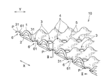
- FIG. 1 is an enlarged perspective view showing a main part of an embodiment of the three-dimensional sheet of the present invention.
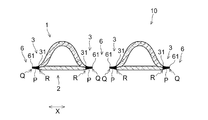
- 2 is a cross-sectional view taken along line II-II in FIG.
- FIG. 3 is a graph showing the relationship between the seal strength and the seal area ratio when two nonwoven fabrics composed of the same single resin thermoplastic resin are partially fused.
- FIG. 4 is a diagram for explaining a method for producing a measurement sample for obtaining the relationship between the seal strength and the seal area ratio in FIG. 3 and a method for measuring the seal strength using the produced measurement sample.
- FIG. 5 is a graph showing the relationship between the seal strength and the seal area ratio when two nonwoven fabrics composed of long fibers having a core-sheath structure are partially fused.
- FIG. 6 is a schematic diagram showing a manufacturing apparatus suitably used for manufacturing the three-dimensional sheet shown in FIG.
- FIG. 7 is a diagram illustrating a state in which a through hole is formed in the sheet forming fused portion using the first roll and the second heat roll in the manufacturing apparatus illustrated in FIG. 6.
- FIG. 1 is a perspective view schematically showing a main part of a three-dimensional sheet with a partial cross section
- FIG. 2 is a cross-sectional view taken along the line II-II shown in FIG.
- the first nonwoven fabric 1 and the second nonwoven fabric 2 that are laminated to each other are partially heat-sealed to form a sheet-forming fused portion 3, and the first nonwoven fabric 1 is formed into a sheet.
- the first nonwoven fabric 1 and the second nonwoven fabric 2 are partially heat-sealed, thereby forming a large number of sheet-forming fused portions 3.
- the first nonwoven fabric 1 protrudes in the direction opposite to the second nonwoven fabric 2 side at portions other than the sheet-forming fused portion 3 to form a plurality of convex portions 4 having internal cavities.
- the surface by the side of the 2nd nonwoven fabric 2 is substantially flat, and the unevenness
- the convex part 4 by the side of the 1st nonwoven fabric 1 arrange
- the three-dimensional sheet 10 has a longitudinal direction X and a width direction Y orthogonal thereto.
- the longitudinal direction X of the three-dimensional sheet 10 looks at the main orientation directions of the constituent fibers of the first sheet base material 11 and the second sheet base material 12, and is in the fiber orientation direction.
- the width direction Y of the three-dimensional sheet 10 matches the CD direction perpendicular to the MD direction.
- the MD direction (X direction) is also a conveyance direction when the three-dimensional sheet 10 is manufactured.
- the convex portion 4 that is a non-fused portion is surrounded by a plurality of sheet-forming fused portions 3 that are spaced apart from each other.
- the periphery is surrounded by the landing portion 3.
- the number of the sheet forming fusion parts 3 surrounding the convex part 4 is not limited to four, and may be two, three, five, six, or seven or more, for example.
- the number of the sheet-forming fusion parts 3 surrounding the convex part 4 is preferably 4 or more, more preferably 5 or more, more preferably 8 or less, and still more preferably 6 or less. It is.
- the protrusions 4 are arranged in the longitudinal direction X so as to form a line at a certain interval. It is formed in multiple rows in the direction Y. Further, the convex portions 4 are also arranged in a row at a constant interval in the width direction Y, and such rows are formed in multiple rows in the longitudinal direction X.
- the convex portion 4 constituting the row and the convex portion 4 constituting another row adjacent to the row in the width direction Y. are arranged with a half-pitch shift.
- the convex portion 4 constituting the row and the convex portion 4 constituting another row adjacent to the row in the longitudinal direction X are shifted by a half pitch. It is arranged.
- the convex portions 4 that are hollow inside do not exist independently independently, but are adjacent to the entire circumference of the convex portion 4 when attention is paid to any one convex portion 4. 4 is connected.
- the height of the connecting part 5 between the convex parts 4 is lower than the height of the top part of the convex part 4.
- the top of the connecting portion 5 is located higher than the fused portion 3 for sheet formation.
- the sheet forming fusion part 3 is located at the center of each concave part of the concave-convex structure of the three-dimensional sheet 10, and each concave part exists independently.
- each convex portion 4 is preferably a dome-like shape, a flat rectangular parallelepiped, or a truncated quadrangular pyramid having a smoothly rounded ridgeline as a whole, and the three-dimensional sheet 10 of the present embodiment. As shown in FIG. 1, it has a rounded dome shape.
- each sheet-forming fusion part 3 in plan view is preferably a circular shape, a rectangular shape, a track shape, a regular polygonal shape, or the like.
- the three-dimensional sheet 10 of the present embodiment as shown in FIG. In addition, it has a circular shape.
- the sheet forming fusion part 3 has a through hole having an outer peripheral edge 61 having a shape similar to the shape of the contour 31 inside the contour 31. 6 is provided.
- Each through-hole 6 is formed through the first nonwoven fabric 1 and the second nonwoven fabric 2 inside one of the sheet forming fused portions 3.
- the shape of each through-hole 6 in plan view is a similar shape obtained by uniformly reducing the shape of the sheet-forming fused portion 3.
- the three-dimensional sheet 10 of this embodiment as shown in FIG. It has a shape.
- the three-dimensional sheet 10 includes the through-hole 6 inside the sheet-forming fusion part 3, as shown in FIG. 2, in the three-dimensional sheet 10, the contour 31 and the through-hole in the sheet-forming fusion part 3.
- the first nonwoven fabric 1 and the second nonwoven fabric 2 are joined to each other at a portion P between the outer peripheral edge 61 and the outer periphery 61.
- the inner edge portion Q on the outer peripheral edge 61 side of the through hole 6 in the portion P has a state in which the fiber shape of the long fibers constituting the first nonwoven fabric 1 and the second nonwoven fabric 2 described later does not exist in a sectional view. It has become. Specifically, as shown in FIG.
- the portion P is a portion having a width between the outline 31 of the sheet forming fusion portion 3 and the outer peripheral edge 61 of the through hole 6 and is formed in an annular shape.
- Such an annular portion P has an inner edge Q on the outer peripheral edge 61 side of the through hole 6 and an outer edge R on the contour 31 side of the sheet forming fused part 3.
- a long fiber melt dissolves uniformly and it is in the state which became a film without a fiber shape any longer.
- the outer edge part R in the said part P it becomes a state in which the fiber shape of the long fiber which comprises the 1st nonwoven fabric 1 and the 2nd nonwoven fabric 2 exists, ie, the state which is not made into a film completely, seeing a cross section. ing.
- the degree of film formation of the annular part P becomes smaller as the part is concentrically separated from the inner edge Q side toward the outer edge R side. That is, in the annular portion P, the interfiber distance of the long fibers constituting the first nonwoven fabric 1 and the second nonwoven fabric 2 is gradually widened from the inner edge portion Q side to the outer edge portion R side. It forms a gradational structure. Whether or not a gradation structure is formed is determined by the following method.
- the sample of the three-dimensional sheet 10 is immersed in liquid nitrogen and sufficiently frozen.
- a commercially available razor is sufficiently immersed in liquid nitrogen.
- a portion near the outer edge portion R and a portion near the inner edge portion Q are cut along the thickness direction using the razor.
- the surface opposite to the razor blade is hit with a hammer or the like, and cutting is performed instantaneously.
- the cut surface is observed with an electron microscope, and the thicknesses of these parts are measured.
- the thickness in the vicinity of the inner edge portion Q is compared with the thickness in the vicinity of the outer edge portion R, and the thickness in the vicinity of the outer edge portion R> the thickness in the vicinity of the inner edge portion Q, it is determined that “a gradational structure is formed”. .
- the 1st nonwoven fabric 1 and the 2nd nonwoven fabric 2 are the nonwoven fabrics which fixed the web which consists of a long fiber by the heat-fusion part, As this nonwoven fabric, the layer of a spunbond nonwoven fabric, a meltblown nonwoven fabric, or a spunbond, and the layer of a meltblown A laminated nonwoven fabric or the like is used.
- the long fibers constituting the first nonwoven fabric 1 and the second nonwoven fabric 2 are single layer fibers formed by uniformly spinning a molten thermoplastic resin.
- the “single-layer fiber” means a single-layer structure in which a fiber formed by spinning does not include a concentric or eccentric core-sheath fiber or a side-by-side fiber. Means that the fiber.
- the fiber diameter of the long fibers is preferably 0.5 dtex or more, more preferably 0.8 dtex or more, 5.0 dtex or less, and particularly preferably 4.0 dtex or less.
- thermoplastic resin constituting the first nonwoven fabric 1 and the second nonwoven fabric 2 examples include polyolefin resins, polyester resins, polyamide resins, acrylonitrile resins, vinyl resins, and vinylidene resins.
- polyolefin resin examples include polyethylene, polypropylene, and polybuden.
- polyester resin examples include polyethylene terephthalate and polybutylene terephthalate. Nylon etc. are mentioned as a polyamide-type resin.
- vinyl resin include polyvinyl chloride.
- vinylidene resin examples include polyvinylidene chloride.
- one of these various resins can be used alone or in combination of two or more, and a modified product of these various resins can also be used.
- these various resins are preferably resins containing 50 to 100% by mass of any one or more of homopolymers, random copolymers, and block copolymers. Moreover, the resin which mixed these homopolymer, random copolymer, or block copolymer may be sufficient.
- the first nonwoven fabric 1 and the second nonwoven fabric 2 are preferably composed of the same thermoplastic resin.
- the thermoplastic resin constituting the first nonwoven fabric 1 and the second nonwoven fabric 2 is a single resin. It is preferable.
- the single resin include a polyethylene resin made of a homopolymer, a polypropylene resin made of a homopolymer, or a polyethylene terephthalate resin made of a homopolymer, and a polypropylene resin made of a homopolymer is preferable from the viewpoint of spinnability. .
- the above viewpoint is that the peel strength between the first nonwoven fabric 1 and the second nonwoven fabric 2 is sealed if the inventor has the same single resin as the thermoplastic resin constituting the first nonwoven fabric 1 and the second nonwoven fabric 2. This is proved by finding that a constant strength can be obtained regardless of the area.
- FIG. 3 plots the relationship between the seal strength and the seal area ratio when the first nonwoven fabric 1 and the second nonwoven fabric 2 composed of the same single resin thermoplastic resin are partially fused.
- a first nonwoven fabric 1 and a second nonwoven fabric 2 having a length of 200 mm in the longitudinal direction X and a width of 50 mm in the width direction Y are prepared, and they are overlapped.
- a plurality of heat-sealed seal wires 32 having a length of 30 mm in the longitudinal direction X and a seal width of 2 mm are arranged and bonded (sealed) to the portion C with a constant interval (pitch) in the width direction Y to produce a measurement sample S To do.
- Such a measurement sample S is manufactured by changing the interval (pitch) in the width direction Y of the heat-sealing seal line, and a plurality of measurement samples having different seal area ratios are manufactured.
- the tensile strength tester for example, Tensilon tensile test manufactured by Orientec Co., Ltd.
- the machine is mounted on a chuck (10 mm between chucks) and pulled at a tensile speed of 300 mm / min, and the maximum load point (seal strength) until the measurement sample breaks is measured.
- FIG. 3 is a plot of the relationship between the seal strength and the seal area ratio thus measured. Further, FIG.
- FIG. 5 shows the seal strength and the seal area ratio when the first nonwoven fabric and the second nonwoven fabric composed of long fibers having a core-sheath structure composed of polyethylene terephthalate resin and polyethylene resin are partially fused. The relationship with is plotted.
- a measurement sample is prepared and the seal strength is measured as in FIG.
- the seal strength increases with an increase in the seal area ratio.
- a non-woven fabric having a core-sheath structure is heat-sealed (sealed)
- a film is formed at the fused (sealed) portion, but the high melting point fibers forming the core maintain its fiber shape in the cross section. Therefore, each of the first nonwoven fabric and the second nonwoven fabric constituting the fusion (seal) part is less damaged by heat in the fusion (seal) part, and when peeling shown in FIG. It is considered that peeling occurs at the interface between the first nonwoven fabric and the second nonwoven fabric, and as a result, the peeling strength increases in proportion to the seal area.
- the present inventor fused the first nonwoven fabric 1 and the second nonwoven fabric 2 made of the same single resin thermoplastic resin as shown in FIG.
- the present inventors have found that the seal strength is substantially constant regardless of the seal area ratio. Considering the cause of such a phenomenon, it seems that it is impossible to keep the fiber structure in the fusion (seal) part because the fibers are made of the same single resin. It is thought that the 1st nonwoven fabric and 2nd nonwoven fabric which comprise a part receive the influence by a heat
- the present inventor has found that the fibers are partially fused without losing the fiber shape of the long fibers in the weakly fused portion on the outer edge R side.
- the peel strength when the first nonwoven fabric 1 and the second nonwoven fabric 2 composed of a single resin thermoplastic resin are fused is not the peel strength of the fusion (seal) portion, but the fusion (seal) It is considered that the strength is substantially constant regardless of the seal area.
- thermoplastic resin which comprises the 1st nonwoven fabric 1 and the 2nd nonwoven fabric 2 is the same single resin, a fixed intensity
- the manufacturing method of the three-dimensional sheet 10 includes meshing the first roll 11 having a concavo-convex shape on the peripheral surface and the second roll 12 having a concavo-convex shape meshing with the concavo-convex shape of the first roll on the peripheral surface.
- a first non-woven fabric 1 positioned on the convex portion 11a of the first roll 11 after the shaping step and the shaping step of forming the irregularities on the first non-woven fabric 1 by biting into the part, and the shaping step A fusion hole opening step in which the first heat roll 13 and the second heat roll 14 are joined to form the sheet forming fusion part 3 and the through hole 6 is formed in the sheet formation fusion part 3.
- the second roll 12, the first heat roll 13, and the second heat roll 14 are disposed to face the first roll 11, and the second roll 12, the first heat roll 13, and the second heat roll 14 are arranged from the upstream side in the rotation direction R of the first roll 11 toward the downstream side. It arrange
- first roll 11 and the second roll 12 whose peripheral surfaces are uneven for example, the one described in Japanese Patent Application Laid-Open No. 2004-174234 of the prior application of the present applicant can be used.
- the 1st heat roll 13 and the 2nd heat roll 14 are flat anvil rolls which do not have unevenness in a peripheral surface, respectively.
- the first nonwoven fabric 1 is unwound from the raw fabric (not shown) of the first nonwoven fabric 1.
- the second nonwoven fabric 2 is fed out from the raw fabric (not shown) of the second nonwoven fabric 2. Then, as shown in FIG. 6, the first nonwoven fabric 1 that has been fed out is bitten into the meshing portion between the first roll and the second roll 12, and the first nonwoven fabric 1 is shaped unevenly.
- the second nonwoven fabric 2 is overlapped with the first nonwoven fabric 1 being continuously sucked and held on the peripheral surface of the first roll 11.
- the pressure is sandwiched between the first heat roll 13 having a smooth circumferential surface.
- both the first roll 11 and the first heat roll 13 or only the first heat roll 13 are heated to a predetermined temperature.
- the first nonwoven fabric 1 and the second nonwoven fabric 2 located on the convex portion 11a of the first roll 11, that is, on the teeth of each gear are joined by thermal fusion to form the fused portion 3 for sheet formation.
- the first nonwoven fabric 1 and the second nonwoven fabric 2 that are joined by heat-sealing are superposed on the peripheral surface of the first roll 11 while being sucked and held.
- the superposed material is moved and clamped between the first roll 11 and the second heat roll 14 having a smooth circumferential surface.
- both the first roll 11 and the second heat roll 14 or only the second heat roll 14 are heated to a predetermined temperature.
- the thermoplastic that has further constituted the first nonwoven fabric 1 and the second nonwoven fabric 2 on the convex portion 11a of the first roll 11, that is, on the fused portion 3 for sheet formation located on the teeth of each gear.
- the resin is melted, and the melted resin moves around the convex portion 11 a to form the through hole 6. Specifically, the melted resin moves from the center of the convex portion 11a to a site gradually concentrically outward to form the through-hole 6 in the fused portion 3 for sheet formation. To do.
- the inner edge Q on the outer peripheral edge 61 side is the fiber shape of the constituent fibers.
- the outer edge R on the contour 31 side is in a state in which the fiber shape of the constituent fibers is present, that is, in a state in which it is not completely formed into a film.
- the through hole 6 is formed in the sheet forming fused part 3 in this manner, only the portion P between the outline 31 of the sheet forming fused part 3 and the outer peripheral edge 61 of the through hole 6 is used.
- the three-dimensional sheet 10 to which the nonwoven fabric 1 and the second nonwoven fabric 2 are joined is continuously manufactured.
- the three-dimensional sheet 10 of the present embodiment described above is made of an absorbent article such as a disposable diaper, a sanitary napkin, a panty liner (orimono sheet), an incontinence pad, etc., with the first nonwoven fabric 1 side facing the wearer's skin side. It is used as a surface sheet. That is, the 1st nonwoven fabric 1 will come to form the surface (skin opposing surface) turned to a wearer's skin side, when the three-dimensional sheet 10 is used as a surface sheet of an absorbent article, and the 2nd nonwoven fabric 2 will be formed. Forms a surface (non-skin-facing surface) that faces the collector side that constitutes the absorbent article.
- an absorbent article such as a disposable diaper, a sanitary napkin, a panty liner (orimono sheet), an incontinence pad, etc.
- the three-dimensional sheet 10 of the present embodiment is formed by joining at a sheet-forming fused portion 3 in which a first nonwoven fabric 1 and a second nonwoven fabric 2 that are laminated to each other are partially arranged. Therefore, when used as a top sheet of an absorbent article, the hollow convex portion 4 is less likely to be crushed when worn as compared to a single-layer solid sheet. Moreover, since the long fiber which comprises the 1st nonwoven fabric 1 and the 2nd nonwoven fabric 2 is a single layer fiber formed by spinning
- the contact area with the skin at the time of wear is suppressed by each convex part 4, and liquid return can be reduced, and it can be expected to reduce redness and rash. It can also be expected to suppress the spread of soft stool and reduce the adhesion of stool to the skin. Furthermore, since the through-hole 6 is formed in the sheet forming fusion part 3, it is expected that the liquid residue is reduced, the liquid return is further reduced, and redness and rash are further reduced. Moreover, it can be expected that the spread of soft stool is further suppressed and the adhesion of stool to the skin is further reduced.
- thermoplastic resin which comprises the 1st nonwoven fabric 1 and the 2nd nonwoven fabric 2 uses the same thing, the peeling strength (seal strength) will improve by the improvement in compatibility, and the solid sheet 10 of this embodiment will improve the sheet. Even if the 1st nonwoven fabric 1 and the 2nd nonwoven fabric 2 are joined only by the part P between the outline 31 of the formation fusion
- the peel strength of the first nonwoven fabric 1 and the second nonwoven fabric 2 that can withstand actual use can be obtained, and the laminate is more difficult to peel off during use.
- the first nonwoven fabric 1 and the second nonwoven fabric 2 if a spunbond nonwoven fabric manufactured using a polypropylene resin made of a homopolymer that is a single resin is used, the fused portion 3 for forming a sheet by pressure is used. It is expected that the through-hole 6 is easily opened, the liquid return is reduced, and redness and rash are reduced.
- the three-dimensional sheet 10 preferably has the following configuration.
- the height of the convex portion 4 is preferably 1 mm or more and 20 mm or less, and more preferably 3 mm or more and 15 mm or less.
- the number of convex portions 4 per unit area (1 cm 2 ) of the three-dimensional sheet 10 is preferably 1 or more and 15 or less, and more preferably 3 or more and 12 or less. Further, the number of through holes 6 per unit area (1 cm 2 ) of the three-dimensional sheet 10 is preferably 1 or more and 50 or less, and more preferably 4 or more and 30 or less.
- the bottom area (S1) of the convex portion 4 is preferably 1 mm 2 or more and 400 mm 2 or less, and more preferably 4 mm 2 or more and 300 mm 2 or less.
- Area of the sheet forming fused portions 3 (S2) is more preferably preferably at 1 mm 2 or more 50 mm 2 or less, 1 mm 2 or more 36 mm 2 or less.
- the area (S2) of the sheet forming fused portion 3 means the area of the region surrounded by the outline 31 of the sheet forming fused portion 3.
- the opening area (S3) of the through hole 6 is preferably 1 mm 2 or more and 100 mm 2 or less, and more preferably 2 mm 2 or more and 50 mm 2 or less.
- the opening area (S3) of the through hole 6 is. It means the area of the region surrounded by the outer peripheral edge 61 of the through hole 6.
- the length of the through-hole 6 is preferably 1 mm or more and 10 mm or less, and more preferably 2 mm or more and 7 mm or less.
- the length of the sheet forming fused part 3 is preferably about 0.1 mm or more and 5 mm or less.
- “the length of the through-hole 6” means the length of the through-hole 6 at the widest position
- “the length of the sheet-forming fused portion 3” means the sheet-formed fused portion. 3 means the length at the widest position.
- the width of the annular portion P (the length in the X direction in FIG. 2) is preferably 3% or more and 20% or less of the length of the fused portion 3 for sheet formation, and is preferably 5% or more and 15% or less. More preferably. Specifically, the width of the portion P is preferably about 0.5 mm or more and 5 mm or less.
- the method for confirming the width of the annular portion P is as follows. The three-dimensional sheet 10 is immersed in liquid nitrogen and frozen sufficiently. Similarly, a commercially available razor is sufficiently immersed in liquid nitrogen. The annular portion P is cut along the thickness direction using a cooled razor.
- the surface opposite to the razor blade is hit with a hammer or the like to cut immediately.
- the cut portion is observed with a microscope magnified about 100 times, the region where the fiber state can be visually recognized is determined as the outer edge R, and the region where the fiber is not visible is determined as the inner edge Q, and the distance between R and Q Is the width of P.
- the peel strength between the first nonwoven fabric 1 and the second nonwoven fabric 2 in the three-dimensional sheet 10 is preferably 0.2 N / 30 mm or more, and more preferably 0.5 N / 30 mm or more.
- limiting in particular in the upper limit of the said peeling strength Although it is so preferable that it is high, if it is about 3 N / 30mm as an upper limit, the effect which is fully satisfied will be acquired.
- the peel strength is 200 mm in the longitudinal direction X and the solid sheet 10 is cut to 30 mm in the width direction Y to produce a cut sample. The peel strength between the first nonwoven fabric 1 and the second nonwoven fabric 2 in this cut sample is determined in the X direction.
- the second nonwoven fabric 2 constituting the three-dimensional sheet 10 has a higher hydrophilicity than the first nonwoven fabric 1 constituting the three-dimensional sheet 10.
- the “hydrophilicity” is determined based on the contact angle of the fiber measured by the method described below. Specifically, a high hydrophilicity is synonymous with a small contact angle, and a low hydrophilicity is synonymous with a large contact angle.
- a fiber is taken out from a predetermined portion of the first nonwoven fabric 1 or the second nonwoven fabric 2 constituting the three-dimensional sheet 10, and the contact angle of water with the fiber is measured.
- an automatic contact angle meter MCA-J manufactured by Kyowa Interface Science Co., Ltd. is used as a measuring device. Distilled water is used to measure the contact angle.
- the amount of liquid discharged from an ink jet type water droplet discharge part (manufactured by Cluster Technology Co., Ltd., pulse injector CTC-25 having a discharge part hole diameter of 25 ⁇ m) is set to 20 picoliters, and a water drop is dropped just above the fiber.
- the state of dripping is recorded on a high-speed recording device connected to a horizontally installed camera.
- the recording device is preferably a personal computer incorporating a high-speed capture device from the viewpoint of image analysis or image analysis later.
- an image is recorded every 17 msec.
- the first image of water drops on the fiber taken out from the non-woven fabric is attached to the attached software FAMAS (software version is 2.6.2, analysis method is droplet method, analysis method is ⁇ / 2 method)
- the image processing algorithm is non-reflective, the image processing image mode is frame, the threshold level is 200, and the curvature is not corrected). And the contact angle.
- the basis weight of the second nonwoven fabric 2 constituting the three-dimensional sheet 10 is preferably higher than the basis weight of the first nonwoven fabric 1 constituting the three-dimensional sheet 10.
- the basis weight of the second nonwoven fabric 2 is preferably 8 g / m 2 or more, more preferably 10 g / m 2 or more, and preferably 25 g / m 2 or less. More preferably, it is 20 g / m 2 or less, specifically 8 g / m 2 or more and 25 g / m 2 or less, and more preferably 10 g / m 2 or more and 20 g / m 2 or less.
- the basis weight of the first nonwoven fabric 1 is preferably 8 g / m 2 or more, more preferably 10 g / m 2 or more, and preferably 20 g / m 2 or less, and 18 g / m 2 or less. More specifically, it is preferably 8 g / m 2 or more and 20 g / m 2 or less, more preferably 10 g / m 2 or more and 18 g / m 2 or less.
- the formation of the sheet-forming fused portion 3 and the formation of the through holes 6 are continuously performed, but may be performed intermittently.
- fusion part 3 for sheet formation is formed with the 1st roll 11 and the 1st heat roll 13 of an upstream, Then, the 1st roll 11 and the downstream 1st roll.
- the two heat rolls 14 form the through holes 6, but the sheet forming fusion part 3 and the through holes 6 may be formed only by the first roll 11 and the upstream first heat roll 13. .
- the sheet is made by superposing the first nonwoven fabric 1 on the second nonwoven fabric 2.
- the through hole 6 may be formed while forming the forming fusion part 3.
- the first nonwoven fabric and the second nonwoven fabric laminated together are partially heat-sealed to form a sheet-forming fused portion, and the first nonwoven fabric is surrounded by the sheet-forming fused portion.
- the first nonwoven fabric and the second nonwoven fabric are nonwoven fabrics in which a web composed of long fibers is fixed by a heat-sealing part,
- the long fiber is a single-layer fiber formed by uniformly spinning a molten thermoplastic resin
- the sheet forming fusion part includes a through hole having an outer peripheral edge having a shape similar to the shape of the outline on the inner side of the outline, and the outline and the outside of the through hole in the sheet forming fusion part.
- the said 1st nonwoven fabric and the said 2nd nonwoven fabric are the three-dimensional sheets as described in said ⁇ 1> whose said thermoplastic resin to comprise is the same.
- ⁇ 3> The three-dimensional sheet according to ⁇ 1> or ⁇ 2>, wherein the thermoplastic resin is a single resin.
- ⁇ 4> The three-dimensional sheet according to any one of ⁇ 1> to ⁇ 3>, wherein the peel strength between the first nonwoven fabric and the second nonwoven fabric is 0.2 N / 30 mm or more.
- ⁇ 5> ⁇ 1> in which the fiber shape of the long fibers does not exist in the inner edge portion on the outer peripheral edge side in the portion between the outline of the fusion forming portion for sheet formation and the outer peripheral edge of the through hole.
- ⁇ 6> The three-dimensional sheet according to any one of ⁇ 1> to ⁇ 5>, wherein the second nonwoven fabric has a higher hydrophilicity than the hydrophilicity of the first nonwoven fabric.
- the basis weight of the second nonwoven fabric is higher than the basis weight of the first nonwoven fabric, and the basis weight of the first nonwoven fabric is 8 g / m 2 or more, and any one of ⁇ 1> to ⁇ 6>
- ⁇ 8> The three-dimensional sheet according to any one of the above items ⁇ 1> to ⁇ 7>, wherein the surface of the second nonwoven fabric side is substantially flat, and irregularities having large undulations are formed on the first nonwoven fabric side. .
- the convex portion which is the non-fused portion is surrounded by a plurality of the sheet forming fused portions spaced apart from each other, and the number of the sheet forming fused portions surrounding the convex portion is:
- the convex portions are arranged in a row at a certain interval in the longitudinal direction X, and such rows are formed in multiple rows in the width direction Y, and the convex portions have a width of In the direction Y, it is arranged so as to form a line at a certain interval.
- Each of the convex portions that are hollow inside does not exist independently independently of each other, but when attention is paid to any one convex portion, it is connected to adjacent convex portions around the entire convex portion.
- the height of the connecting part between the convex parts is lower than the height of the top part of the convex part, and the top part of the connecting part is at a position higher than the fused part for forming the sheet,
- the forming fused portion is located at the center of each concave portion of the concavo-convex structure of the three-dimensional sheet, and the concave portion is any one of the above ⁇ 1> to ⁇ 10> 3.
- the three-dimensional sheet according to 1.
- the cross-sectional shape of the convex portion is one of a dome-like shape, a flat rectangular parallelepiped shape, and a truncated quadrangular pyramid with a smoothly rounded ridgeline as a whole, and the fused portion for sheet formation is planar
- One through hole in the fused portion for forming the sheet is formed inside the fused portion for forming the sheet so as to penetrate the first nonwoven fabric and the second nonwoven fabric, and the through hole is viewed in plan view.
- the three-dimensional sheet according to any one of the above items ⁇ 1> to ⁇ 12> which is a similar shape obtained by uniformly reducing the shape of the fused portion for forming the sheet and is circular.
- the first non-woven fabric and the second non-woven fabric are joined at a portion P between the contour of the fused portion for forming the sheet and the outer peripheral edge of the through-hole,
- the fiber shape of the long fibers constituting the first nonwoven fabric and the second nonwoven fabric does not exist in a sectional view, and the portion P
- the fiber shape does not exist and is in a filmed state, and in the portion R away from the through hole in the portion P, the first nonwoven fabric and the portion
- There is a fiber shape of the long fibers constituting the second nonwoven fabric and it is in a state where it is not completely formed into a film, and the degree of film formation of the portion P is as far as
- the degree is small Kunar wherein ⁇ 1> bulky sheet according to any one of the - ⁇ 13>.
- fusion part and the outer periphery of the said through-hole comprises the 1st nonwoven fabric 1 and the 2nd nonwoven fabric, when this part P is seen in a cross section along the thickness direction.
- the distance between the fibers of the long fibers is gradually increased from the inner edge portion Q side toward the outer edge portion R side, and forms a gradation-like structure, according to any one of the above items ⁇ 1> to ⁇ 14> Solid sheet.
- ⁇ 16> Any one of the above items ⁇ 1> to ⁇ 15>, where the thickness in the vicinity of the inner edge Q is compared with the thickness in the vicinity of the outer edge R, and the thickness in the vicinity of the outer edge R> the thickness in the vicinity of the inner edge Q.
- the first nonwoven fabric and the second nonwoven fabric are nonwoven fabrics in which a web composed of long fibers is fixed by a heat-sealing portion.
- the long fibers constituting the first nonwoven fabric and the second nonwoven fabric are single-layer fibers formed by uniformly spinning a molten thermoplastic resin, and the single-layer fibers are concentric or eccentric. ⁇ 1> to ⁇ 17>, wherein the core-sheath fiber or side-by-side fiber is not included, and the fiber formed by spinning is a uniform single-layer fiber. Solid sheet. ⁇ 19>
- the thermoplastic resin constituting the first nonwoven fabric and the second nonwoven fabric is any one of polyolefin resin, polyester resin, polyamide resin, acrylonitrile resin, vinyl resin, vinylidene resin, and polyolefin resin.
- polyester resin either polyethylene terephthalate or polybutylene terephthalate is used, the polyamide resin is nylon, the vinyl resin is polyvinyl chloride, and vinylidene. Polyvinylidene chloride is used as a resin, and one of these various resins is used alone or in combination of two or more. Further, these various resins are one or more of homopolymers, random copolymers, and block copolymers. 50-100 Or amount% resin containing these homopolymers, random copolymers, or the a resin mixed with a block copolymer ⁇ 1> bulky sheet according to any one of the - ⁇ 18>.
- the first nonwoven fabric and the second nonwoven fabric are spunbond nonwoven fabrics in which a web composed of long fibers is fixed by a heat-sealing portion, and the thermoplastic resin constituting the first nonwoven fabric and the second nonwoven fabric 2 is a homopolymer.
- the height of the protrusions is 1 mm or more and 20 mm or less, preferably 3 mm or more and 15 mm or less, and the number of the protrusions per unit area (1 cm 2 ) of the three-dimensional sheet is 1 or more and 15 or less.
- the number of the through holes per unit area (1 cm 2 ) of the three-dimensional sheet is 1 or more and 50 or less, preferably 4 or more and 30 or less.
- Bottom area of the convex portion (S1) is at 1 mm 2 or more 400 mm 2 or less, preferably 4 mm 2 or more 300 mm 2 or less, the area of the sheet forming fused portion (S2) is 1 mm 2 or more 50 mm 2
- the opening area (S3) of the through hole 6 is 1 mm 2 or more and 100 mm 2 or less, preferably 2 mm 2 or more and 50 mm 2 or less, and the length of the through hole 6 is 1 mm or more and 10 mm or less, 2 mm
- the peel strength between the first nonwoven fabric and the second nonwoven fabric in the three-dimensional sheet is 0.2 N / 30 mm or more, preferably 0.5 N / 30 mm or more, and the upper limit is 3 N / 30 mm ⁇ 1
- the basis weight of the second nonwoven fabric constituting the three-dimensional sheet is higher than the basis weight of the first nonwoven fabric constituting the three-dimensional sheet,
- the basis weight of the second nonwoven fabric is 8 g / m 2 or more, preferably 10 g / m 2 or more, and 25 g / m 2 or less, preferably 20 g / m 2 or less, preferably Is 8 g / m 2 or more and 25 g / m 2 or less, more preferably 10 g / m 2 or more and 20 g / m 2 or less,
- the basis weight of the first nonwoven fabric is 8 g / m 2 or more, preferably 10 g / m 2 or more, and 20 g / m 2 or less, preferably 18 g / m 2 or less, 8 g is preferably / m 2 or more 20 g / m 2 or less, the bulky sheet according to any one of the 10 g / m 2 or more 18
- ⁇ 26> An absorbent article, wherein the three-dimensional sheet according to any one of ⁇ 1> to ⁇ 25> is used as a top sheet of an absorbent article such that the first nonwoven fabric side faces the wearer's skin side.
- the method for producing a three-dimensional sheet according to any one of the above ⁇ 1> to ⁇ 25> The first nonwoven fabric is fed out from the original fabric of the first nonwoven fabric. Separately, the second nonwoven fabric is fed out from the original fabric of the second nonwoven fabric, and the fed first nonwoven fabric is taken as a first roll.
- the first nonwoven fabric 1 is concavo-convex shaped by being bitten into the meshing portion with the second roll, and then the second nonwoven fabric is sucked and held on the peripheral surface of the first roll.
- the non-woven fabrics are superposed, and the superposed one is sandwiched between the first roll and the first heat roll having a smooth peripheral surface.
- both the first roll and the first heat roll or the first heat Only the roll is heated, and then, the superposition of the first nonwoven fabric and the second nonwoven fabric joined by heat fusion is moved under the state of being continuously sucked and held on the peripheral surface of the first roll.
- the superposition Clamping is performed between one roll and a second heat roll having a smooth surface, and both the first roll and the second heat roll or only the second heat roll at this time are heated, and the first roll In the sheet forming fusion part located on the teeth of the gears that are on the convex part of the sheet, the thermoplastic resin constituting the first nonwoven fabric and the second nonwoven fabric is further melted, and the molten resin is A manufacturing method of a three-dimensional sheet formed by moving around the convex portion to form the through hole. ⁇ 29> The first roll and the first heat roll on the upstream side form the fused portion for sheet formation, and then the through hole is formed by the first roll and the second heat roll on the downstream side.
- the sheet-forming fused portion and the through hole are formed by the first roll and the upstream first heat roll, and the sandwiching pressure and temperature between the first roll and the upstream first heat roll, etc.
- Example 1 1st nonwoven fabric and 2nd nonwoven fabric comprised from the fiber (2.0 dtex) which consists of polypropylene resin which is single resin are partially heat-sealed using the manufacturing apparatus shown in FIG. 6, and it shows in FIG. A three-dimensional sheet was produced.
- the number of convex portions per unit area (1 cm 2 ) of the three-dimensional sheet was 3, and the number of through holes per unit area (1 cm 2 ) of the three-dimensional sheet was 12.
- the bottom area of the projection (S1) is 9 mm 2
- opening area of the through-hole (S3) was 2 mm 2.
- the length of the through hole was 1 mm
- the length of the fused part for sheet formation was 0.5 mm.
- the peel strength of the three-dimensional sheet measured by the measurement method described above was 1.2 N / 30 mm.
- Example 2 A three-dimensional sheet of Example 2 was produced in the same manner as Example 1 except that the first nonwoven fabric and the second nonwoven fabric composed of fibers (2.2 dtex) made of polyethylene terephthalate resin, which is a single resin, were used.
- the peel strength of the three-dimensional sheet of Example 2 was 1.0 N / 30 mm.
- Comparative Example 1 Except for using a first nonwoven fabric and a second nonwoven fabric composed of core-sheath composite fibers (2.6 dtex, fiber length 51 mm) using polyethylene for the core and polyethylene terephthalate resin for the sheath, the same as in Example 1 A three-dimensional sheet of Comparative Example 1 was produced. The peel strength of the three-dimensional sheet of Comparative Example 1 was 0.13 N / 30 mm.
- the surface sheet is removed from the product of “Merry's (registered trademark) 2013” manufactured by Kao Corporation, and the three-dimensional sheet of Examples 1 or 2 or the three-dimensional sheet of Comparative Example 1 is used instead.
- a disposable diaper was prepared so as to face the skin side.
- a mounting test was performed as follows to evaluate the presence or absence of peeling of the first nonwoven fabric and the second nonwoven fabric.
- Test environment temperature 27 ° C, humidity 60% Wearers 1 to 3 infants
- the obtained results are shown in Table 1.
- the evaluation of the presence or absence of peeling of the first nonwoven fabric and the second nonwoven fabric was expressed in the following three stages.
- the disposable diaper using the three-dimensional sheet of Examples 1 and 2 as the top sheet is more in comparison with the disposable diaper using the three-dimensional sheet of Comparative Example 1 as the top sheet. It was found that it was difficult to peel off from the fused part. Accordingly, the disposable diaper using the three-dimensional sheet of Examples 1 and 2 as the top sheet is difficult to peel off from the fused portion between the first nonwoven fabric and the second nonwoven fabric during use, reduces liquid return, and reduces redness and rash. Can be expected to do.
Abstract
Description
前記第1不織布及び前記第2不織布は、長繊維からなるウェブを熱融着部により固定した不織布である。
前記長繊維は、溶融した熱可塑性樹脂を均一に紡糸して形成された単層繊維である。
前記シート形成用融着部は、その輪郭よりも内側に、該輪郭の形状に相似する形状の外周縁を有する貫通孔を備える。
前記シート形成用融着部における前記輪郭と該貫通孔の外周縁との間の部分で、前記第1不織布及び前記第2不織布が接合されている。 In the present invention, the first nonwoven fabric and the second nonwoven fabric laminated together are partially heat-sealed to form a sheet-forming fused portion, and the first nonwoven fabric is surrounded by the sheet-forming fused portion. Further, the present invention provides a three-dimensional sheet that protrudes in a direction away from the second non-woven fabric in the non-fused portion and has many hollow convex portions inside.
The first nonwoven fabric and the second nonwoven fabric are nonwoven fabrics in which a web made of long fibers is fixed by a heat-sealing portion.
The long fiber is a single layer fiber formed by uniformly spinning a molten thermoplastic resin.
The sheet forming fusion part includes a through hole having an outer peripheral edge having a shape similar to the shape of the contour on the inner side of the contour.
The first nonwoven fabric and the second nonwoven fabric are joined at a portion between the contour and the outer peripheral edge of the through-hole in the sheet-forming fused portion.
従って、第1不織布1及び第2不織布2を構成する熱可塑性樹脂が、同一の単一樹脂であれば、シール面積によらずに一定の強度が得られ、シート形成用融着部3の輪郭31と貫通孔6の外周縁61との間の部分Pだけで第1不織布1及び第2不織布2が接合されていたとしても、実使用に耐えうる、第1不織布1及び第2不織布2の剥離強度が得られることが推測される。以上のことから、第1不織布1及び第2不織布2として、単一樹脂であるホモポリマーからなるポリプロピレン樹脂を用いて形成されたスパンボンド不織布を使用することが最も好ましい。 In general, as shown in FIG. 5, the seal strength increases with an increase in the seal area ratio. Consider the cause of this phenomenon. When a non-woven fabric having a core-sheath structure is heat-sealed (sealed), a film is formed at the fused (sealed) portion, but the high melting point fibers forming the core maintain its fiber shape in the cross section. Therefore, each of the first nonwoven fabric and the second nonwoven fabric constituting the fusion (seal) part is less damaged by heat in the fusion (seal) part, and when peeling shown in FIG. It is considered that peeling occurs at the interface between the first nonwoven fabric and the second nonwoven fabric, and as a result, the peeling strength increases in proportion to the seal area. However, as shown in FIG. 3, the present inventor fused the first
Therefore, if the thermoplastic resin which comprises the 1st
立体シート10の製造方法は、周面が凹凸形状となっている第1ロール11と第1ロールの凹凸形状と噛み合い形状となっている凹凸形状を周面に有する第2ロール12との噛み合わせ部に噛み込ませて第1不織布1を凹凸賦形する賦形工程と、該賦形工程の後、第2不織布2を、第1ロール11における凸部11a上に位置する第1不織布1と、第1ヒートロール13及び第2ヒートロール14により接合してシート形成用融着部3を形成して該シート形成用融着部3内に貫通孔6を形成する融着開孔工程とを備えている。第1ロール11に対して、第2ロール12、第1ヒートロール13及び第2ヒートロール14は、対向配置されており、第1ロール11の回転方向Rの上流側から下流側に向かって第1ロール11の周面に対して、その順に配置されている。周面が凹凸形状となっている第1ロール11及び第2ロール12に関しては、例えば、本出願人の先願の特開2004-174234号公報に記載のもの等を用いることができる。第1ヒートロール13及び第2ヒートロール14は、それぞれ周面に凹凸を有していないフラットなアンビルロールである。 Next, the manufacturing method of the three-
The manufacturing method of the three-
本実施形態の立体シート10は、図1に示すように、互いに積層された第1不織布1及び第2不織布2が部分的に配されたシート形成用融着部3で接合して形成されているので、単層の立体シートに比べ、吸収性物品の表面シートとして用いたときに、着用時に中空の凸部4が潰れ難くなっている。また、第1不織布1及び第2不織布2を構成する長繊維が、溶融した熱可塑性樹脂を均一に紡糸して形成された単層繊維であるので、シート形成用融着部3における剥離強度が高く、使用時に積層間が剥がれ難くなっている。また、各凸部4により着用時における肌との接触面積が抑えられ、液戻りが低減し、赤みやかぶれを低減することが期待できる。また、軟便の拡がりを抑制し、便の肌への付着を低減することが期待できる。更に、シート形成用融着部3内に貫通孔6が形成されているので、液残りが低減し、液戻りが更に低減し、赤みやかぶれを更に低減することが期待できる。また、軟便の拡がりを更に抑制し、便の肌への付着を更に低減することが期待できる。 The effect at the time of using the
As shown in FIG. 1, the three-
立体シート10の単位面積(1cm2)当たりの凸部4の数は、1個以上15個以下であることが好ましく、3個以上12個以下であることが更に好ましい。
また、立体シート10の単位面積(1cm2)当たりの貫通孔6の数は、1個以上50個以下であることが好ましく、4個以上30個以下であることが更に好ましい。 The height of the
The number of
Further, the number of through
環状の前記部分Pの幅の確認方法は次のとおりとする。立体シート10を液体窒素に浸漬し、十分に凍結する。また、市販のカミソリを同様に液体窒素に十分に浸漬する。環状の前記部分Pを、冷やしたカミソリを用いて厚み方向に沿って切断する。その際、切断面の形状がカミソリによる切断の影響を受けなくすことを目的で、カミソリの刃と反対面をハンマー等で叩き瞬時に切断する。切断箇所を、100倍程度に拡大した顕微鏡で観察し、繊維の状態が視認できる領域を外縁部Rとし、フィルム状で繊維が視認できない領域を内縁部Qとして判断し、RとQとの距離をもってPの幅とする。 Further, the width of the annular portion P (the length in the X direction in FIG. 2) is preferably 3% or more and 20% or less of the length of the fused
The method for confirming the width of the annular portion P is as follows. The three-
立体シート10を構成する第1不織布1又は第2不織布2の所定の部位から繊維を取り出し、その繊維に対する水の接触角を測定する。測定装置として、協和界面科学株式会社製の自動接触角計MCA-Jを用いる。接触角の測定には蒸留水を用いる。インクジェット方式水滴吐出部(クラスターテクノロジー社製、吐出部孔径が25μmのパルスインジェクターCTC-25)から吐出される液量を20ピコリットルに設定して、水滴を、繊維の真上に滴下する。滴下の様子を水平に設置されたカメラに接続された高速度録画装置に録画する。録画装置は後に画像解析や画像解析をする観点から、高速度キャプチャー装置が組み込まれたパーソナルコンピュータが望ましい。本測定では、17msec毎に画像が録画される。録画された映像において、不織布から取り出した繊維に水滴が着滴した最初の画像を、付属ソフトFAMAS(ソフトのバージョンは2.6.2、解析手法は液滴法、解析方法はθ/2法、画像処理アルゴリズムは無反射、画像処理イメージモードはフレーム、スレッシホールドレベルは200、曲率補正はしない、とする)にて画像解析を行い、水滴の空気に触れる面と繊維のなす角を算出し、接触角とする。第1不織布1又は第2不織布2から取り出した繊維は、繊維長1mmに裁断し、該繊維を接触角計のサンプル台に載せて、水平に維持する。該繊維1本につき異なる2箇所の接触角を測定する。N=5本の接触角を小数点以下1桁まで計測し、合計10箇所の測定値を平均した値(小数点以下第2桁で四捨五入)を接触角と定義する。 [Measurement method of contact angle]
A fiber is taken out from a predetermined portion of the first
互いに積層された第1不織布及び第2不織布が部分的に熱融着されてシート形成用融着部が形成され、該第1不織布が、該シート形成用融着部で囲まれた非融着部において該第2不織布から離れる方向に突出して、内部が中空の凸部を多数形成している立体シートであって、
前記第1不織布及び前記第2不織布は、長繊維からなるウェブを熱融着部により固定した不織布であり、
前記長繊維は、溶融した熱可塑性樹脂を均一に紡糸して形成された単層繊維であり、
前記シート形成用融着部は、その輪郭よりも内側に、該輪郭の形状に相似する形状の外周縁を有する貫通孔を備え、該シート形成用融着部における前記輪郭と該貫通孔の外周縁との間の部分で、前記第1不織布及び前記第2不織布が接合されている立体シート。 <1>
The first nonwoven fabric and the second nonwoven fabric laminated together are partially heat-sealed to form a sheet-forming fused portion, and the first nonwoven fabric is surrounded by the sheet-forming fused portion. Projecting in a direction away from the second non-woven fabric in the part, and a solid sheet in which a large number of hollow convex portions are formed,
The first nonwoven fabric and the second nonwoven fabric are nonwoven fabrics in which a web composed of long fibers is fixed by a heat-sealing part,
The long fiber is a single-layer fiber formed by uniformly spinning a molten thermoplastic resin,
The sheet forming fusion part includes a through hole having an outer peripheral edge having a shape similar to the shape of the outline on the inner side of the outline, and the outline and the outside of the through hole in the sheet forming fusion part. A three-dimensional sheet in which the first nonwoven fabric and the second nonwoven fabric are joined at a portion between the periphery.
前記第1不織布及び前記第2不織布は、構成する前記熱可塑性樹脂が同一である前記<1>に記載の立体シート。
<3>
前記熱可塑性樹脂は、単一樹脂からなる前記<1>又は<2>に記載の立体シート。
<4>
前記第1不織布と前記第2不織布との剥離強度は、0.2N/30mm以上である前記<1>~<3>の何れか1に記載の立体シート。
<5>
前記シート形成用融着部の輪郭と前記貫通孔の外周縁との間の部分における該外周縁側の内縁部には、断面視して前記長繊維の繊維形状が存在していない前記<1>~<4>の何れか1に記載の立体シート。
<6>
前記第2不織布は、その親水度が、前記第1不織布の親水度よりも高い前記<1>~<5>の何れか1に記載の立体シート。
<7>
前記第2不織布は、その坪量が、前記第1不織布の坪量よりも高く、該第1不織布の坪量は、8g/m2以上である前記<1>~<6>の何れか1に記載の立体シート。
<8>
前記立体シートは、前記第2不織布側の面がほぼ平坦であり、前記第1不織布側に起伏の大きな凹凸が形成されている前記<1>~<7>の何れか1に記載の立体シート。 <2>
The said 1st nonwoven fabric and the said 2nd nonwoven fabric are the three-dimensional sheets as described in said <1> whose said thermoplastic resin to comprise is the same.
<3>
The three-dimensional sheet according to <1> or <2>, wherein the thermoplastic resin is a single resin.
<4>
The three-dimensional sheet according to any one of <1> to <3>, wherein the peel strength between the first nonwoven fabric and the second nonwoven fabric is 0.2 N / 30 mm or more.
<5>
<1> in which the fiber shape of the long fibers does not exist in the inner edge portion on the outer peripheral edge side in the portion between the outline of the fusion forming portion for sheet formation and the outer peripheral edge of the through hole. The three-dimensional sheet according to any one of <4>.
<6>
The three-dimensional sheet according to any one of <1> to <5>, wherein the second nonwoven fabric has a higher hydrophilicity than the hydrophilicity of the first nonwoven fabric.
<7>
The basis weight of the second nonwoven fabric is higher than the basis weight of the first nonwoven fabric, and the basis weight of the first nonwoven fabric is 8 g / m 2 or more, and any one of <1> to <6> The solid sheet as described in 1.
<8>
The three-dimensional sheet according to any one of the above items <1> to <7>, wherein the surface of the second nonwoven fabric side is substantially flat, and irregularities having large undulations are formed on the first nonwoven fabric side. .
前記非融着部である前記凸部は、周囲を、相互に離間した複数の前記シート形成用融着部によって囲まれており、前記凸部を囲む前記シート形成用融着部の数は、4個以上であり、好ましくは5個以上であり、また、8個以下であり、好ましくは6個以下である前記<1>~<8>の何れか1に記載の立体シート。
<10>
前記凸部は、長手方向Xに、一定の間隔を空けて一列をなすように配置されており、このような列が幅方向Yに、多列に形成されており、前記凸部は、幅方向Yにも、一定の間隔を空けて一列をなすように配置されており、このような列が長手方向Xに、多列に形成されており、長手方向Xに延びる一つの列に着目すると、該列を構成する凸部と、該列に幅方向Yに隣り合う別の列を構成する凸部とが、半ピッチずれて配されており、幅手方向Yに延びる一つの列に着目すると、該列を構成する凸部と、該列に長手方向Xに隣り合う別の列を構成する凸部とが、半ピッチずれて配されている前記<1>~<9>の何れか1に記載の立体シート。
<11>
内部が中空の前記各凸部は、それぞれが別個に独立して存在しているのではなく、任意の一つの凸部に着目したとき、該凸部の全周囲にて隣接する凸部と連結しており、凸部どうしの連結部の高さは、凸部の頂部の高さよりも低くなっており、前記連結部の頂部は、前記シート形成用融着部より高い位置にあり、該シート形成用融着部は、前記立体シートの凹凸構造の各凹部の中心に位置しており、該凹部は、それぞれが別個に独立して存在している前記<1>~<10>の何れか1に記載の立体シート。
<12>
前記凸部の断面形状としては、全体として稜線が滑らかに丸みを帯びた、ドーム状の形状、扁平な直方体、或いは截頭四角錐体の何れかであり、前記シート形成用融着部を平面視した形状としては、円形状、矩形状、トラック形状の何れかである前記<1>~<11>の何れか1に記載の立体シート。
<13>
前記シート形成用融着部における前記貫通孔は、該シート形成用融着部の内側に1個、前記第1不織布及び前記第2不織布を貫通して形成されており、該貫通孔を平面視した形状としては、該シート形成用融着部の形状を一様に縮小した相似形状であり円形状である前記<1>~<12>の何れか1に記載立体シート。
<14>
前記立体シートにおいては、前記シート形成用融着部における輪郭と前記貫通孔の外周縁との間の部分Pで、前記第1不織布及び前記第2不織布が接合されており、前記部分Pのうち、前記貫通孔の外周縁側の内縁部Qにおいては、断面視して、前記第1不織布及び前記第2不織布を構成する長繊維の繊維形状が存在していない状態となっており、前記部分Pにおける内縁部Qにおいては、繊維形状が存在せずフィルム化した状態となっており、前記部分Pのうち、前記貫通孔から離れた部位Rにおいては、断面視して、前記第1不織布及び前記第2不織布を構成する長繊維の繊維形状が存在し、完全にはフィルム化していない状態であり、該部分Pのフィルム化の程度は、前記貫通孔の中心から、同心円状に離れた部位ほど、その程度は小さくなる前記<1>~<13>の何れか1に記載の立体シート。
<15>
前記シート形成用融着部における輪郭と前記貫通孔の外周縁との間の前記部分Pは、該部分Pを厚み方向に沿って断面視したとき、第1不織布1及び第2不織布を構成する長繊維の繊維間距離が、内縁部Q側から外縁部R側に向かって漸次広くなっており、グラデーション的な構造を形成している前記<1>~<14>の何れか1に記載の立体シート。
<16>
前記内縁部Q近傍の厚みと、前記外縁部R近傍の厚みを比べたとき、該外縁部R近傍の厚み>該内縁部Q近傍の厚みとなっている前記<1>~<15>の何れか1に記載の立体シート。
<17>
前記第1不織布及び前記第2不織布は、長繊維からなるウェブを熱融着部により固定した不織布であり、該不織布としては、スパンボンド不織布、メルトブローン不織布、又はスパンボンドの層とメルトブローンの層との積層不織布の何れかである前記<1>~<16>の何れか1に記載の立体シート。
<18>
前記第1不織布及び前記第2不織布を構成する長繊維は、溶融した熱可塑性樹脂を均一に紡糸して形成された単層繊維であり、該単層繊維は、同芯型若しくは偏芯型の芯鞘型の繊維、又はサイド・バイ・サイド型の繊維を含まず、紡糸して形成された繊維が均一な一層構造の繊維である前記<1>~<17>の何れか1に記載の立体シート。
<19>
前記第1不織布及び前記第2不織布を構成する熱可塑性樹脂としては、ポリオレフィン系樹脂、ポリエステル系樹脂、ポリアミド系樹脂、アクリロニトリル系樹脂、ビニル系樹脂、ビニリデン系樹脂の何れかであり、ポリオレフィン系樹脂としてはポリエチレン、ポリプロピレン、ポリブデンの何れかであり、ポリエステル系樹脂としてはポリエチレンテレフタレート、ポリブチレンテレフタレート何れかであり、ポリアミド系樹脂としてはナイロンであり、ビニル系樹脂としてはポリ塩化ビニルであり、ビニリデン系樹脂としてはポリ塩化ビニリデンであり、これら各種樹脂の1種を単独で又は2種以上を混合して用い、更に、これら各種樹脂は、ホモポリマー、ランダムコポリマー、ブロックコポリマーの何れか1種以上を50~100質量%含んだ樹脂か、これらホモポリマー、ランダムコポリマー、或いはブロックコポリマーを混合した樹脂である前記<1>~<18>の何れか1に記載の立体シート。
<20>
前記第1不織布及び前記第2不織布は、長繊維からなるウェブを熱融着部により固定したスパンボンド不織布であり、前記第1不織布及び前記第2不織布2を構成する熱可塑性樹脂はホモポリマーからなるポリプロピレン樹脂である前記<1>~<19>の何れか1に記載の立体シート。
<21>
前記凸部の高さは、1mm以上20mm以下であり、好ましくは3mm以上15mm以下であり、前記立体シートの単位面積(1cm2)当たりの前記凸部の数は、1個以上15個以下であり、好ましくは3個以上12個以下であり、前記立体シートの単位面積(1cm2)当たりの前記貫通孔の数は、1個以上50個以下であり、好ましくは4個以上30個以下である前記<1>~<20>の何れか1に記載の立体シート。
<22>
前記凸部の底部面積(S1)は、1mm2以上400mm2以下であり、好ましくは4mm2以上300mm2以下であり、前記シート形成用融着部の面積(S2)は、1mm2以上50mm2以下であり、好ましくは1mm2以上36mm2以下である前記<1>~<21>の何れか1に記載の立体シート。
<23>
前記貫通孔6の開孔面積(S3)は、1mm2以上100mm2以下であり、好ましくは2mm2以上50mm2以下であり、前記貫通孔6の長さは、1mm以上10mm以下であり、2mm以上7mm以下であり、また、シート形成用融着部3の長さは0.1mm以上5mm以下である前記<1>~<22>の何れか1に記載の立体シート。
<24>
前記立体シートにおける前記第1不織布と前記第2不織布との剥離強度は、0.2N/30mm以上であり、好ましくは0.5N/30mm以上であり、上限値は3N/30mmである前記<1>~<23>の何れか1に記載の立体シート。
<25>
前記立体シートを構成する前記第2不織布は、その坪量が、該立体シートを構成する前記第1不織布の坪量よりも高く、
前記第2不織布の坪量は、8g/m2以上であり、好ましくは、10g/m2以上であり、そして、25g/m2以下であり、好ましくは、20g/m2以下であり、好ましくは8g/m2以上25g/m2以下であり、更に好ましくは、10g/m2以上20g/m2以下であり、
前記第1不織布の坪量は、8g/m2以上であり、好ましくは、10g/m2以上であり、そして、20g/m2以下であり、18g/m2以下であることが好ましく、8g/m2以上20g/m2以下であることが好ましく、10g/m2以上18g/m2以下であることが更に好ましい前記<1>~<24>の何れか1に記載の立体シート。 <9>
The convex portion which is the non-fused portion is surrounded by a plurality of the sheet forming fused portions spaced apart from each other, and the number of the sheet forming fused portions surrounding the convex portion is: The three-dimensional sheet according to any one of <1> to <8>, wherein the number is 4 or more, preferably 5 or more, and 8 or less, preferably 6 or less.
<10>
The convex portions are arranged in a row at a certain interval in the longitudinal direction X, and such rows are formed in multiple rows in the width direction Y, and the convex portions have a width of In the direction Y, it is arranged so as to form a line at a certain interval. When such a line is formed in multiple lines in the longitudinal direction X, attention is paid to one line extending in the longitudinal direction X. The convex portion constituting the row and the convex portion constituting another row adjacent to the row in the width direction Y are arranged with a half-pitch shift, and attention is paid to one row extending in the width direction Y. Then, any one of the above items <1> to <9>, wherein the convex portions constituting the row and the convex portions constituting another row adjacent to the row in the longitudinal direction X are arranged with a half-pitch shift. 3. The three-dimensional sheet according to 1.
<11>
Each of the convex portions that are hollow inside does not exist independently independently of each other, but when attention is paid to any one convex portion, it is connected to adjacent convex portions around the entire convex portion. The height of the connecting part between the convex parts is lower than the height of the top part of the convex part, and the top part of the connecting part is at a position higher than the fused part for forming the sheet, The forming fused portion is located at the center of each concave portion of the concavo-convex structure of the three-dimensional sheet, and the concave portion is any one of the above <1> to <10> 3. The three-dimensional sheet according to 1.
<12>
The cross-sectional shape of the convex portion is one of a dome-like shape, a flat rectangular parallelepiped shape, and a truncated quadrangular pyramid with a smoothly rounded ridgeline as a whole, and the fused portion for sheet formation is planar The three-dimensional sheet according to any one of <1> to <11>, wherein the viewed shape is any one of a circular shape, a rectangular shape, and a track shape.
<13>
One through hole in the fused portion for forming the sheet is formed inside the fused portion for forming the sheet so as to penetrate the first nonwoven fabric and the second nonwoven fabric, and the through hole is viewed in plan view. The three-dimensional sheet according to any one of the above items <1> to <12>, which is a similar shape obtained by uniformly reducing the shape of the fused portion for forming the sheet and is circular.
<14>
In the three-dimensional sheet, the first non-woven fabric and the second non-woven fabric are joined at a portion P between the contour of the fused portion for forming the sheet and the outer peripheral edge of the through-hole, In the inner edge portion Q on the outer peripheral edge side of the through hole, the fiber shape of the long fibers constituting the first nonwoven fabric and the second nonwoven fabric does not exist in a sectional view, and the portion P In the inner edge portion Q, the fiber shape does not exist and is in a filmed state, and in the portion R away from the through hole in the portion P, the first nonwoven fabric and the portion There is a fiber shape of the long fibers constituting the second nonwoven fabric, and it is in a state where it is not completely formed into a film, and the degree of film formation of the portion P is as far as a concentric circle from the center of the through hole. The degree is small Kunar wherein <1> bulky sheet according to any one of the - <13>.
<15>
The said part P between the outline in the said sheet | seat formation fusion | fusion part and the outer periphery of the said through-hole comprises the 1st
<16>
Any one of the above items <1> to <15>, where the thickness in the vicinity of the inner edge Q is compared with the thickness in the vicinity of the outer edge R, and the thickness in the vicinity of the outer edge R> the thickness in the vicinity of the inner edge Q. The three-dimensional sheet according to
<17>
The first nonwoven fabric and the second nonwoven fabric are nonwoven fabrics in which a web composed of long fibers is fixed by a heat-sealing portion. The three-dimensional sheet according to any one of <1> to <16>, which is any one of the laminated nonwoven fabrics.
<18>
The long fibers constituting the first nonwoven fabric and the second nonwoven fabric are single-layer fibers formed by uniformly spinning a molten thermoplastic resin, and the single-layer fibers are concentric or eccentric. <1> to <17>, wherein the core-sheath fiber or side-by-side fiber is not included, and the fiber formed by spinning is a uniform single-layer fiber. Solid sheet.
<19>
The thermoplastic resin constituting the first nonwoven fabric and the second nonwoven fabric is any one of polyolefin resin, polyester resin, polyamide resin, acrylonitrile resin, vinyl resin, vinylidene resin, and polyolefin resin. As the polyester resin, either polyethylene terephthalate or polybutylene terephthalate is used, the polyamide resin is nylon, the vinyl resin is polyvinyl chloride, and vinylidene. Polyvinylidene chloride is used as a resin, and one of these various resins is used alone or in combination of two or more. Further, these various resins are one or more of homopolymers, random copolymers, and block copolymers. 50-100 Or amount% resin containing these homopolymers, random copolymers, or the a resin mixed with a block copolymer <1> bulky sheet according to any one of the - <18>.
<20>
The first nonwoven fabric and the second nonwoven fabric are spunbond nonwoven fabrics in which a web composed of long fibers is fixed by a heat-sealing portion, and the thermoplastic resin constituting the first nonwoven fabric and the second
<21>
The height of the protrusions is 1 mm or more and 20 mm or less, preferably 3 mm or more and 15 mm or less, and the number of the protrusions per unit area (1 cm 2 ) of the three-dimensional sheet is 1 or more and 15 or less. Yes, preferably 3 or more and 12 or less, and the number of the through holes per unit area (1 cm 2 ) of the three-dimensional sheet is 1 or more and 50 or less, preferably 4 or more and 30 or less. The three-dimensional sheet according to any one of the above items <1> to <20>.
<22>
Bottom area of the convex portion (S1) is at 1 mm 2 or more 400 mm 2 or less, preferably 4 mm 2 or more 300 mm 2 or less, the area of the sheet forming fused portion (S2) is 1 mm 2 or more 50 mm 2 The solid sheet according to any one of the above items <1> to <21>, which is preferably 1 mm 2 or more and 36 mm 2 or less.
<23>
The opening area (S3) of the through
<24>
The peel strength between the first nonwoven fabric and the second nonwoven fabric in the three-dimensional sheet is 0.2 N / 30 mm or more, preferably 0.5 N / 30 mm or more, and the upper limit is 3 N / 30 mm <1 The solid sheet according to any one of> to <23>.
<25>
The basis weight of the second nonwoven fabric constituting the three-dimensional sheet is higher than the basis weight of the first nonwoven fabric constituting the three-dimensional sheet,
The basis weight of the second nonwoven fabric is 8 g / m 2 or more, preferably 10 g / m 2 or more, and 25 g / m 2 or less, preferably 20 g / m 2 or less, preferably Is 8 g / m 2 or more and 25 g / m 2 or less, more preferably 10 g / m 2 or more and 20 g / m 2 or less,
The basis weight of the first nonwoven fabric is 8 g / m 2 or more, preferably 10 g / m 2 or more, and 20 g / m 2 or less, preferably 18 g / m 2 or less, 8 g is preferably / m 2 or more 20 g / m 2 or less, the bulky sheet according to any one of the 10 g / m 2 or more 18 g / m 2 or less is still more preferable that the <1> to <24>.
前記<1>~<25>の何れか1に記載の立体シートを、前記第1不織布側が着用者の肌側を向くようにして吸収性物品の表面シートとして用いた吸収性物品。
<27>
前記吸収性物品は使い捨ておむつである、前記<26>に記載の吸収性物品。
<28>
前記<1>~<25>の何れか1に記載の立体シートの製造方法であって、
前記第1不織布の原反から前記第1不織布を繰り出し、これとは別に、前記第2不織布の原反から前記第2不織布を繰り出し、そして、繰り出された該第1不織布を、第1ロールと第2ロールとの噛み合わせ部に噛み込ませて該第1不織布1を凹凸賦形し、次いで、該第1不織布を前記第1ロールの周面に引き続き吸引保持した状態下に、該第2不織布を重ね合わせ、その重ね合わせたものを、第1ロールと周面平滑な第1ヒートロールとの間で挟圧し、このとき該第1ロールと該第1ヒートロールの両方又は該第1ヒートロールのみを加熱しておき、次いで、熱融着によって接合された前記第1不織布及び前記第2不織布の重ね合わせたものを、前記第1ロールの周面に引き続き吸引保持した状態下で移動させ、該重ね合わせたものを、該第1ロールと周面平滑な第2ヒートロールとの間で挟圧し、このときの該第1ロールと該第2ヒートロールの両方又は該第2ヒートロールのみを加熱しておき、該第1ロールにおける凸部上である各歯車の歯の上に位置する前記シート形成用融着部において、更に前記第1不織布及び前記第2不織布を構成していた熱可塑性樹脂を溶融し、溶融した樹脂が該凸部の周囲に移動して前記貫通孔を形成してなる立体シートの製造方法。
<29>
前記第1ロールと上流側の前記第1ヒートロールとで前記シート形成用融着部を形成し、その後、該第1ロールと下流側の前記第2ヒートロールとで、前記貫通孔を形成するか、又は、
前記第1ロール及び上流側の前記第1ヒートロールで、前記シート形成用融着部及び前記貫通孔を形成し、該第1ロール及び上流側の該第1ヒートロールとの挟持圧力と温度等を調整することにより、前記第1不織布を前記第2不織布に重ね合わせたものに対して、該シート形成用融着部を形成しながら、該貫通孔を形成する前記<28>に記載の立体シートの製造方法。 <26>
An absorbent article, wherein the three-dimensional sheet according to any one of <1> to <25> is used as a top sheet of an absorbent article such that the first nonwoven fabric side faces the wearer's skin side.
<27>
The absorbent article according to <26>, wherein the absorbent article is a disposable diaper.
<28>
The method for producing a three-dimensional sheet according to any one of the above <1> to <25>,
The first nonwoven fabric is fed out from the original fabric of the first nonwoven fabric. Separately, the second nonwoven fabric is fed out from the original fabric of the second nonwoven fabric, and the fed first nonwoven fabric is taken as a first roll. The first
<29>
The first roll and the first heat roll on the upstream side form the fused portion for sheet formation, and then the through hole is formed by the first roll and the second heat roll on the downstream side. Or
The sheet-forming fused portion and the through hole are formed by the first roll and the upstream first heat roll, and the sandwiching pressure and temperature between the first roll and the upstream first heat roll, etc. The three-dimensional body as described in <28>, wherein the through hole is formed while the sheet-forming fused portion is formed on the first nonwoven fabric superimposed on the second nonwoven fabric by adjusting Sheet manufacturing method.
単一樹脂であるポリプロピレン樹脂からなる繊維(2.0dtex)から構成された第1不織布及び第2不織布を、図6に示す製造装置を用いて部分的に熱融着して、図1に示す立体シートを製造した。立体シートの単位面積(1cm2)当たりの凸部の数は3個であり、立体シートの単位面積(1cm2)当たりの貫通孔の数は12個であった。尚、凸部の底部面積(S1)は9mm2であり、シート形成用融着部の面積(S2)5mm2であり、貫通孔の開孔面積(S3)は2mm2であった。また、貫通孔の長さは1mmであり、シート形成用融着部の長さは0.5mmであった。次に上述した測定方法により測定した立体シートの剥離強度は、1.2N/30mmであった。 [Example 1]
1st nonwoven fabric and 2nd nonwoven fabric comprised from the fiber (2.0 dtex) which consists of polypropylene resin which is single resin are partially heat-sealed using the manufacturing apparatus shown in FIG. 6, and it shows in FIG. A three-dimensional sheet was produced. The number of convex portions per unit area (1 cm 2 ) of the three-dimensional sheet was 3, and the number of through holes per unit area (1 cm 2 ) of the three-dimensional sheet was 12. Incidentally, the bottom area of the projection (S1) is 9 mm 2, the area of the sheet forming fused portion (S2) 5 mm 2, opening area of the through-hole (S3) was 2 mm 2. Moreover, the length of the through hole was 1 mm, and the length of the fused part for sheet formation was 0.5 mm. Next, the peel strength of the three-dimensional sheet measured by the measurement method described above was 1.2 N / 30 mm.
単一樹脂であるポリエチレンテレフタレート樹脂からなる繊維(2.2dtex)から構成された第1不織布及び第2不織布を用いる以外は、実施例1と同様にして実施例2の立体シートを製造した。実施例2の立体シートの剥離強度は、1.0N/30mmであった。 [Example 2]
A three-dimensional sheet of Example 2 was produced in the same manner as Example 1 except that the first nonwoven fabric and the second nonwoven fabric composed of fibers (2.2 dtex) made of polyethylene terephthalate resin, which is a single resin, were used. The peel strength of the three-dimensional sheet of Example 2 was 1.0 N / 30 mm.
芯部にポリエチレン、鞘部にポリエチレンテレフタレート樹脂を用いた芯鞘複合繊維(2.6dtex、繊維長51mm)から構成された第1不織布及び第2不織布を用いる以外は、実施例1と同様にして比較例1の立体シートを製造した。比較例1の立体シートの剥離強度は、0.13N/30mmであった。 [Comparative Example 1]
Except for using a first nonwoven fabric and a second nonwoven fabric composed of core-sheath composite fibers (2.6 dtex, fiber length 51 mm) using polyethylene for the core and polyethylene terephthalate resin for the sheath, the same as in Example 1 A three-dimensional sheet of Comparative Example 1 was produced. The peel strength of the three-dimensional sheet of Comparative Example 1 was 0.13 N / 30 mm.
花王株式会社製の「メリーズ(登録商標)2013年製」の製品から表面シートを取り除き、実施例1~2の立体シート又は比較例1の立体シートを替わりに用い、第1不織布側が着用者の肌側を向くようにして使い捨ておむつを作製した。実施例1~2の立体シート又は比較例1の立体シートを表面シートに用いた使い捨ておむつに関し、以下のようにして装着テストを行い、第1不織布及び第2不織布の剥離の有無を評価した。
<試験条件>
テスト環境:温度27℃、湿度60%
装着者 幼児1~3名
各使い捨ておむつに関して、装着5時間経過後の第1不織布及び第2不織布の剥離の有無を、以下の基準で評価した。得られた結果を表1に示す。 [Performance evaluation]
The surface sheet is removed from the product of “Merry's (registered trademark) 2013” manufactured by Kao Corporation, and the three-dimensional sheet of Examples 1 or 2 or the three-dimensional sheet of Comparative Example 1 is used instead. A disposable diaper was prepared so as to face the skin side. With respect to the disposable diaper using the three-dimensional sheet of Examples 1 or 2 or the three-dimensional sheet of Comparative Example 1 as the top sheet, a mounting test was performed as follows to evaluate the presence or absence of peeling of the first nonwoven fabric and the second nonwoven fabric.
<Test conditions>
Test environment: temperature 27 ° C, humidity 60%
A:第1不織布と第2不織布との融着部分から全く剥離していない。
B:第1不織布と第2不織布との融着部分から若干剥離している。
C:第1不織布と第2不織布との融着部分から剥離している。 The evaluation of the presence or absence of peeling of the first nonwoven fabric and the second nonwoven fabric was expressed in the following three stages.
A: It has not peeled at all from the fusion | melting part of a 1st nonwoven fabric and a 2nd nonwoven fabric.
B: It has peeled slightly from the fusion | melting part of a 1st nonwoven fabric and a 2nd nonwoven fabric.
C: It peels from the fusion | fusion part of a 1st nonwoven fabric and a 2nd nonwoven fabric.

Claims (29)
- 互いに積層された第1不織布及び第2不織布が部分的に熱融着されてシート形成用融着部が形成され、該第1不織布が、該シート形成用融着部で囲まれた非融着部において該第2不織布から離れる方向に突出して、内部が中空の凸部を多数形成している立体シートであって、
前記第1不織布及び前記第2不織布は、長繊維からなるウェブを熱融着部により固定した不織布であり、
前記長繊維は、溶融した熱可塑性樹脂を均一に紡糸して形成された単層繊維であり、
前記シート形成用融着部は、その輪郭よりも内側に、該輪郭の形状に相似する形状の外周縁を有する貫通孔を備え、該シート形成用融着部における前記輪郭と該貫通孔の外周縁との間の部分で、前記第1不織布及び前記第2不織布が接合されている立体シート。 The first nonwoven fabric and the second nonwoven fabric laminated together are partially heat-sealed to form a sheet-forming fused portion, and the first nonwoven fabric is surrounded by the sheet-forming fused portion. Projecting in a direction away from the second non-woven fabric in the part, and a solid sheet in which a large number of hollow convex portions are formed,
The first nonwoven fabric and the second nonwoven fabric are nonwoven fabrics in which a web composed of long fibers is fixed by a heat-sealing part,
The long fiber is a single-layer fiber formed by uniformly spinning a molten thermoplastic resin,
The sheet forming fusion part includes a through hole having an outer peripheral edge having a shape similar to the shape of the outline on the inner side of the outline, and the outline and the outside of the through hole in the sheet forming fusion part. A three-dimensional sheet in which the first nonwoven fabric and the second nonwoven fabric are joined at a portion between the periphery. - 前記第1不織布及び前記第2不織布は、構成する前記熱可塑性樹脂が同一である請求項1に記載の立体シート。 The three-dimensional sheet according to claim 1, wherein the thermoplastic resin constituting the first nonwoven fabric and the second nonwoven fabric are the same.
- 前記熱可塑性樹脂は、単一樹脂からなる請求項1又は2に記載の立体シート。 The three-dimensional sheet according to claim 1 or 2, wherein the thermoplastic resin is made of a single resin.
- 前記第1不織布と前記第2不織布との剥離強度は、0.2N/30mm以上である請求項1ないし3の何れか一項に記載の立体シート。 The three-dimensional sheet according to any one of claims 1 to 3, wherein a peel strength between the first nonwoven fabric and the second nonwoven fabric is 0.2 N / 30 mm or more.
- 前記シート形成用融着部の輪郭と前記貫通孔の外周縁との間の部分における該外周縁側の内縁部には、断面視して前記長繊維の繊維形状が存在していない請求項1ないし4の何れか一項に記載の立体シート。 The fiber shape of the long fibers does not exist in an inner edge portion on the outer peripheral edge side in a portion between the outline of the fusion forming portion for sheet formation and the outer peripheral edge of the through hole. The solid sheet according to any one of 4.
- 前記第2不織布は、その親水度が、前記第1不織布の親水度よりも高い請求項1ないし5の何れか一項に記載の立体シート。 The three-dimensional sheet according to any one of claims 1 to 5, wherein the second nonwoven fabric has a higher hydrophilicity than the hydrophilicity of the first nonwoven fabric.
- 前記第2不織布は、その坪量が、前記第1不織布の坪量よりも高く、該第1不織布の坪量は、8g/m2以上である請求項1ないし6の何れか一項に記載の立体シート。 The basis weight of the second nonwoven fabric is higher than the basis weight of the first nonwoven fabric, and the basis weight of the first nonwoven fabric is 8 g / m 2 or more. Three-dimensional sheet.
- 前記立体シートは、前記第2不織布側の面がほぼ平坦であり、前記第1不織布側に起伏の大きな凹凸が形成されている請求項1ないし7の何れか一項に記載の立体シート。 The three-dimensional sheet according to any one of claims 1 to 7, wherein the three-dimensional sheet has a substantially flat surface on the second non-woven fabric side and is provided with unevenness on the first non-woven fabric side.
- 前記非融着部である前記凸部は、周囲を、相互に離間した複数の前記シート形成用融着部によって囲まれており、前記凸部を囲む前記シート形成用融着部の数は、4個以上8個以下である請求項1ないし8の何れか一項に記載の立体シート。 The convex portion which is the non-fused portion is surrounded by a plurality of the sheet forming fused portions spaced apart from each other, and the number of the sheet forming fused portions surrounding the convex portion is: The three-dimensional sheet according to any one of claims 1 to 8, wherein the number is 4 or more and 8 or less.
- 長手方向X及びこれと直交する幅方向Yを有し、
前記凸部は、長手方向Xに、一定の間隔を空けて一列をなすように配置されており、このような列が幅方向Yに、多列に形成されており、前記凸部は、幅方向Yにも、一定の間隔を空けて一列をなすように配置されており、このような列が長手方向Xに、多列に形成されており、長手方向Xに延びる一つの列に着目すると、該列を構成する凸部と、該列に幅方向Yに隣り合う別の列を構成する凸部とが、半ピッチずれて配されており、幅手方向Yに延びる一つの列に着目すると、該列を構成する凸部と、該列に長手方向Xに隣り合う別の列を構成する凸部とが、半ピッチずれて配されている請求項1ないし9の何れか一項に記載の立体シート。 Having a longitudinal direction X and a width direction Y perpendicular thereto,
The convex portions are arranged in a row at a certain interval in the longitudinal direction X, and such rows are formed in multiple rows in the width direction Y, and the convex portions have a width of In the direction Y, it is arranged so as to form a line at a certain interval. When such a line is formed in multiple lines in the longitudinal direction X, attention is paid to one line extending in the longitudinal direction X. The convex portion constituting the row and the convex portion constituting another row adjacent to the row in the width direction Y are arranged with a half-pitch shift, and attention is paid to one row extending in the width direction Y. Then, the convex part which comprises this row | line | column, and the convex part which comprises another row | line | column adjacent to the said row | line | column in the longitudinal direction X are arrange | positioned by a half pitch shift | offset | difference. The three-dimensional sheet of description. - 内部が中空の前記各凸部は、任意の一つの凸部に着目したとき、該凸部の全周囲にて隣接する凸部と連結しており、
凸部どうしの連結部の高さは、凸部の頂部の高さよりも低くなっており、
前記連結部の頂部は、前記シート形成用融着部よりも高い位置にあり、
前記シート形成用融着部は、前記立体シートの凹凸構造の各凹部の中心に位置しており、該凹部は、それぞれが別個に独立して存在している請求項1ないし10の何れか一項に記載の立体シート。 Each of the convex portions that are hollow inside is connected to adjacent convex portions around the entire convex portion when attention is paid to any one convex portion,
The height of the connecting part between the convex parts is lower than the height of the top part of the convex part,
The top of the connecting portion is at a position higher than the fused portion for forming the sheet,
The sheet forming fusion part is located at the center of each concave part of the concave-convex structure of the three-dimensional sheet, and each of the concave parts exists independently independently. The solid sheet according to item. - 前記凸部の断面形状が、全体として稜線が滑らかに丸みを帯びた、ドーム状の形状、扁平な直方体、又は截頭四角錐体の何れかであり、
前記シート形成用融着部を平面視した形状が、円形状、矩形状、又はトラック形状の何れかである請求項1ないし11の何れか一項に記載の立体シート。 The cross-sectional shape of the convex part is either a dome-shaped shape, a flat rectangular parallelepiped, or a truncated quadrangular pyramid, with the ridgeline smoothly rounded as a whole,
The three-dimensional sheet according to any one of claims 1 to 11, wherein a shape of the fused portion for sheet formation in plan view is any one of a circular shape, a rectangular shape, and a track shape. - 前記シート形成用融着部における前記貫通孔は、該シート形成用融着部の内側に1個、前記第1不織布及び前記第2不織布を貫通して形成されており、
前記貫通孔を平面視した形状は、前記シート形成用融着部の形状を一様に縮小した相似形状であり且つ円形状である請求項1ないし12の何れか一項に記載立体シート。 The through hole in the sheet forming fusion part is formed inside the sheet forming fusion part, penetrating the first nonwoven fabric and the second nonwoven fabric,
The three-dimensional sheet according to any one of claims 1 to 12, wherein a shape of the through hole in plan view is a similar shape obtained by uniformly reducing the shape of the sheet forming fusion portion and a circular shape. - 前記立体シートにおいては、前記シート形成用融着部における輪郭と前記貫通孔の外周縁との間の部分Pで、前記第1不織布及び前記第2不織布が接合されており、前記部分Pのうち、前記貫通孔の外周縁側の内縁部Qにおいては、断面視して、前記第1不織布及び前記第2不織布を構成する長繊維の繊維形状が存在していない状態となっており、
前記部分Pにおける内縁部Qにおいては、繊維形状が存在せずフィルム化した状態となっており、
前記部分Pのうち、前記貫通孔から離れた部位Rにおいては、断面視して、前記第1不織布及び前記第2不織布を構成する長繊維の繊維形状が存在し、完全にはフィルム化していない状態であり、該部分Pのフィルム化の程度は、前記貫通孔の中心から、同心円状に離れた部位ほど、その程度は小さくなる請求項1ないし13の何れか一項に記載の立体シート。 In the three-dimensional sheet, the first non-woven fabric and the second non-woven fabric are joined at a portion P between the contour of the fused portion for forming the sheet and the outer peripheral edge of the through-hole, In the inner edge portion Q on the outer peripheral edge side of the through-hole, the fiber shape of the long fibers constituting the first nonwoven fabric and the second nonwoven fabric is not present in a cross-sectional view,
In the inner edge portion Q in the portion P, the fiber shape does not exist and is in a filmed state,
Of the portion P, in a portion R away from the through hole, there is a fiber shape of long fibers constituting the first nonwoven fabric and the second nonwoven fabric in a cross-sectional view, and the film is not completely filmed. The three-dimensional sheet according to any one of claims 1 to 13, which is in a state, and the degree of film formation of the portion P becomes smaller as the part is concentrically separated from the center of the through hole. - 前記シート形成用融着部における輪郭と前記貫通孔の外周縁との間の前記部分Pは、該部分Pを厚み方向に沿って断面視したとき、第1不織布1及び第2不織布を構成する長繊維の繊維間距離が、内縁部Q側から外縁部R側に向かって漸次広くなっており、グラデーション的な構造を形成している請求項1ないし14の何れか一項に記載の立体シート。 The said part P between the outline in the said sheet | seat formation fusion | fusion part and the outer periphery of the said through-hole comprises the 1st nonwoven fabric 1 and the 2nd nonwoven fabric, when this part P is seen in a cross section along the thickness direction. The three-dimensional sheet according to any one of claims 1 to 14, wherein a distance between the fibers of the long fibers gradually increases from the inner edge portion Q side to the outer edge portion R side to form a gradation structure. .
- 前記内縁部Q近傍の厚みと、前記外縁部R近傍の厚みを比べたとき、該外縁部R近傍の厚み>該内縁部Q近傍の厚みとなっている請求項1ないし15の何れか一項に記載の立体シート。 16. The thickness in the vicinity of the inner edge Q is compared with the thickness in the vicinity of the outer edge R, and the thickness in the vicinity of the outer edge R> the thickness in the vicinity of the inner edge Q. The solid sheet as described in 1.
- 前記第1不織布及び前記第2不織布は、長繊維からなるウェブを熱融着部により固定した不織布であり、
前記不織布は、スパンボンド不織布、メルトブローン不織布、又はスパンボンドの層とメルトブローンの層との積層不織布の何れかである請求項1ないし16の何れか一項に記載の立体シート。 The first nonwoven fabric and the second nonwoven fabric are nonwoven fabrics in which a web composed of long fibers is fixed by a heat-sealing part,
The three-dimensional sheet according to any one of claims 1 to 16, wherein the nonwoven fabric is any one of a spunbond nonwoven fabric, a meltblown nonwoven fabric, and a laminated nonwoven fabric of a spunbond layer and a meltblown layer. - 前記第1不織布及び前記第2不織布を構成する長繊維は、溶融した熱可塑性樹脂を均一に紡糸して形成された単層繊維であり、該単層繊維は、同芯型若しくは偏芯型の芯鞘型の繊維、又はサイド・バイ・サイド型の繊維を含まず、紡糸して形成された繊維が均一な一層構造の繊維である請求項1ないし17の何れか一項に記載の立体シート。 The long fibers constituting the first nonwoven fabric and the second nonwoven fabric are single-layer fibers formed by uniformly spinning a molten thermoplastic resin, and the single-layer fibers are concentric or eccentric. The three-dimensional sheet according to any one of claims 1 to 17, wherein a core-sheath fiber or a side-by-side fiber is not included, and the fiber formed by spinning is a uniform single-layer fiber. .
- 前記第1不織布及び前記第2不織布を構成する熱可塑性樹脂は、ポリオレフィン系樹脂、ポリエステル系樹脂、ポリアミド系樹脂、アクリロニトリル系樹脂、ビニル系樹脂、ビニリデン系樹脂の何れかであり、
ポリオレフィン系樹脂は、ポリエチレン、ポリプロピレン、ポリブデンの何れかであり、
ポリエステル系樹脂は、ポリエチレンテレフタレート、ポリブチレンテレフタレートの何れかであり、
ポリアミド系樹脂は、ナイロンであり、
ビニル系樹脂は、ポリ塩化ビニルであり、
ビニリデン系樹脂は、ポリ塩化ビニリデンであり、
これら各種樹脂の1種を単独で又は2種以上を混合して用い、更に、これら各種樹脂は、ホモポリマー、ランダムコポリマー、ブロックコポリマーの何れか1種以上を50~100質量%含んだ樹脂か、これらホモポリマー、ランダムコポリマー、或いはブロックコポリマーを混合した樹脂である請求項1ないし18の何れか一項に記載の立体シート。 The thermoplastic resin constituting the first nonwoven fabric and the second nonwoven fabric is any one of a polyolefin resin, a polyester resin, a polyamide resin, an acrylonitrile resin, a vinyl resin, and a vinylidene resin,
The polyolefin-based resin is one of polyethylene, polypropylene, and polybuden,
The polyester resin is either polyethylene terephthalate or polybutylene terephthalate,
Polyamide resin is nylon,
The vinyl resin is polyvinyl chloride,
The vinylidene resin is polyvinylidene chloride,
One of these various resins is used alone or in admixture of two or more. Further, these various resins are resins containing 50 to 100% by mass of one or more of homopolymer, random copolymer and block copolymer. The three-dimensional sheet according to any one of claims 1 to 18, which is a resin obtained by mixing a homopolymer, a random copolymer, or a block copolymer. - 前記第1不織布及び前記第2不織布は、長繊維からなるウェブを熱融着部により固定したスパンボンド不織布であり、前記第1不織布及び前記第2不織布2を構成する熱可塑性樹脂はホモポリマーからなるポリプロピレン樹脂である請求項1ないし19の何れか一項に記載の立体シート。 The first nonwoven fabric and the second nonwoven fabric are spunbond nonwoven fabrics in which a web composed of long fibers is fixed by a heat-sealing portion, and the thermoplastic resin constituting the first nonwoven fabric and the second nonwoven fabric 2 is a homopolymer. The three-dimensional sheet according to any one of claims 1 to 19, which is a polypropylene resin.
- 前記凸部の高さは、1mm以上20mm以下であり、前記立体シートの1cm2当たりの前記凸部の数は、1個以上15個以下であり、前記立体シートの1cm2当たりの前記貫通孔の数は、1個以上50個以下である請求項1ないし20の何れか一項に記載の立体シート。 The height of the convex part is 1 mm or more and 20 mm or less, the number of the convex part per 1 cm 2 of the three-dimensional sheet is 1 or more and 15 or less, and the through-hole per 1 cm 2 of the three-dimensional sheet The number of is one or more and 50 or less, The three-dimensional sheet | seat as described in any one of Claim 1 thru | or 20.
- 前記凸部の底部面積S1は、1mm2以上400mm2以下であり、前記シート形成用融着部の面積S2は、1mm2以上50mm2以下である請求項1ないし21の何れか一項に記載の立体シート。 The bottom part area S1 of the convex part is 1 mm 2 or more and 400 mm 2 or less, and the area S2 of the fused part for sheet formation is 1 mm 2 or more and 50 mm 2 or less. Three-dimensional sheet.
- 前記貫通孔の開孔面積S3は、1mm2以上100mm2以下であり、前記貫通孔の長さは、1mm以上10mm以下であり、また、シート形成用融着部の長さは0.1mm以上5mm以下である請求項1ないし22の何れか一項に記載の立体シート。 The opening area S3 of the through hole is 1 mm 2 or more and 100 mm 2 or less, the length of the through hole is 1 mm or more and 10 mm or less, and the length of the fused portion for sheet formation is 0.1 mm or more. The three-dimensional sheet according to any one of claims 1 to 22, which is 5 mm or less.
- 前記立体シートにおける前記第1不織布と前記第2不織布との剥離強度は、0.2N/30mm以上3N/30mmである請求項1ないし23の何れか一項に記載の立体シート。 The three-dimensional sheet according to any one of claims 1 to 23, wherein a peel strength between the first nonwoven fabric and the second nonwoven fabric in the three-dimensional sheet is 0.2 N / 30 mm or more and 3 N / 30 mm.
- 前記立体シートを構成する前記第2不織布は、その坪量が、該立体シートを構成する前記第1不織布の坪量よりも高く、
前記第2不織布の坪量は、8g/m2以上25g/m2以下であり、
前記第1不織布の坪量は、8g/m2以上20g/m2以下である請求項1ないし24の何れか一項に記載の立体シート。 The basis weight of the second nonwoven fabric constituting the three-dimensional sheet is higher than the basis weight of the first nonwoven fabric constituting the three-dimensional sheet,
The basis weight of the second nonwoven fabric is 8 g / m 2 or more and 25 g / m 2 or less,
The three-dimensional sheet according to any one of claims 1 to 24, wherein the basis weight of the first nonwoven fabric is 8 g / m 2 or more and 20 g / m 2 or less. - 請求項1ないし25の何れか一項に記載の立体シートを、前記第1不織布側が着用者の肌側を向くようにして吸収性物品の表面シートとして用いた吸収性物品。 An absorbent article, wherein the three-dimensional sheet according to any one of claims 1 to 25 is used as a top sheet of an absorbent article such that the first nonwoven fabric side faces the wearer's skin side.
- 前記吸収性物品は使い捨ておむつである、請求項26に記載の吸収性物品。 The absorbent article according to claim 26, wherein the absorbent article is a disposable diaper.
- 請求項1ないし25の何れか一項に記載の立体シートの製造方法であって、
前記第1不織布の原反から前記第1不織布を繰り出し、これとは別に、前記第2不織布の原反から前記第2不織布を繰り出し、そして、繰り出された該第1不織布を、第1ロールと第2ロールとの噛み合わせ部に噛み込ませて該第1不織布1を凹凸賦形し、次いで、該第1不織布を前記第1ロールの周面に引き続き吸引保持した状態下に、該第2不織布を重ね合わせ、その重ね合わせたものを、第1ロールと周面平滑な第1ヒートロールとの間で挟圧し、このとき該第1ロールと該第1ヒートロールの両方又は該第1ヒートロールのみを加熱しておき、次いで、熱融着によって接合された前記第1不織布及び前記第2不織布の重ね合わせたものを、前記第1ロールの周面に引き続き吸引保持した状態下で移動させ、該重ね合わせたものを、該第1ロールと周面平滑な第2ヒートロールとの間で挟圧し、このときの該第1ロールと該第2ヒートロールの両方又は該第2ヒートロールのみを加熱しておき、該第1ロールにおける凸部上である各歯車の歯の上に位置する前記シート形成用融着部において、更に前記第1不織布及び前記第2不織布を構成していた熱可塑性樹脂を溶融し、溶融した樹脂が該凸部の周囲に移動して前記貫通孔を形成してなる立体シートの製造方法。 It is a manufacturing method of the solid sheet according to any one of claims 1 to 25,
The first nonwoven fabric is fed out from the original fabric of the first nonwoven fabric. Separately, the second nonwoven fabric is fed out from the original fabric of the second nonwoven fabric, and the fed first nonwoven fabric is taken as a first roll. The first nonwoven fabric 1 is concavo-convex shaped by being bitten into the meshing portion with the second roll, and then the second nonwoven fabric is sucked and held on the peripheral surface of the first roll. The non-woven fabrics are superposed, and the superposed one is sandwiched between the first roll and the first heat roll having a smooth peripheral surface. At this time, both the first roll and the first heat roll or the first heat Only the roll is heated, and then, the superposition of the first nonwoven fabric and the second nonwoven fabric joined by heat fusion is moved under the state of being continuously sucked and held on the peripheral surface of the first roll. , The superposition Clamping is performed between one roll and a second heat roll having a smooth surface, and both the first roll and the second heat roll or only the second heat roll at this time are heated, and the first roll In the sheet forming fusion part located on the teeth of the gears that are on the convex part of the sheet, the thermoplastic resin constituting the first nonwoven fabric and the second nonwoven fabric is further melted, and the molten resin is A manufacturing method of a three-dimensional sheet formed by moving around the convex portion to form the through hole. - 前記第1ロールと上流側の前記第1ヒートロールとで前記シート形成用融着部を形成し、その後、該第1ロールと下流側の前記第2ヒートロールとで、前記貫通孔を形成するか、又は、
前記第1ロール及び上流側の前記第1ヒートロールで、前記シート形成用融着部及び前記貫通孔を形成し、該第1ロール及び上流側の該第1ヒートロールとの挟持圧力と温度等を調整することにより、前記第1不織布を前記第2不織布に重ね合わせたものに対して、該シート形成用融着部を形成しながら、該貫通孔を形成する請求項28に記載の立体シートの製造方法。 The first roll and the first heat roll on the upstream side form the fused portion for sheet formation, and then the through hole is formed by the first roll and the second heat roll on the downstream side. Or
The sheet-forming fused portion and the through hole are formed by the first roll and the upstream first heat roll, and the sandwiching pressure and temperature between the first roll and the upstream first heat roll, etc. The three-dimensional sheet according to claim 28, wherein the through-hole is formed while the sheet-forming fusion part is formed with respect to the first nonwoven fabric superimposed on the second nonwoven fabric by adjusting Manufacturing method.
Priority Applications (2)
| Application Number | Priority Date | Filing Date | Title |
|---|---|---|---|
| CN201480068557.7A CN105828773B (en) | 2013-12-27 | 2014-11-19 | Stereogram |
| RU2016130324A RU2624300C1 (en) | 2013-12-27 | 2014-11-19 | Three-dimensional sheet |
Applications Claiming Priority (4)
| Application Number | Priority Date | Filing Date | Title |
|---|---|---|---|
| JP2013-272094 | 2013-12-27 | ||
| JP2013272094 | 2013-12-27 | ||
| JP2014229817A JP5960775B2 (en) | 2013-12-27 | 2014-11-12 | Solid sheet and method for producing solid sheet |
| JP2014-229817 | 2014-11-12 |
Publications (1)
| Publication Number | Publication Date |
|---|---|
| WO2015098373A1 true WO2015098373A1 (en) | 2015-07-02 |
Family
ID=53478247
Family Applications (1)
| Application Number | Title | Priority Date | Filing Date |
|---|---|---|---|
| PCT/JP2014/080645 WO2015098373A1 (en) | 2013-12-27 | 2014-11-19 | Three-dimensional sheet |
Country Status (4)
| Country | Link |
|---|---|
| JP (1) | JP5960775B2 (en) |
| CN (1) | CN105828773B (en) |
| RU (1) | RU2624300C1 (en) |
| WO (1) | WO2015098373A1 (en) |
Cited By (25)
| Publication number | Priority date | Publication date | Assignee | Title |
|---|---|---|---|---|
| US9415538B2 (en) | 2010-09-10 | 2016-08-16 | The Procter & Gamble Company | Method for deforming a web |
| CN105877928A (en) * | 2016-04-01 | 2016-08-24 | 泉州市汉威机械制造有限公司 | Hygienic product surface layer material |
| JP2017038925A (en) * | 2015-08-17 | 2017-02-23 | 大王製紙株式会社 | Absorbent article |
| WO2017030136A1 (en) * | 2015-08-17 | 2017-02-23 | 大王製紙株式会社 | Absorbent article |
| US10279535B2 (en) | 2011-04-26 | 2019-05-07 | The Procter & Gamble Company | Method and apparatus for deforming a web |
| WO2019092594A1 (en) * | 2017-11-08 | 2019-05-16 | Texol S.R.L. | Method and apparatus of manufacturing a multilayer absorbing element for sanitary articles |
| EP3431063A4 (en) * | 2016-03-16 | 2019-10-30 | Xiamen Yanjan New Material Co., Ltd | Perforated non-woven fabric and procution method therefor |
| JP2020506773A (en) * | 2017-02-13 | 2020-03-05 | ザ プロクター アンド ギャンブル カンパニーThe Procter & Gamble Company | Laminate for absorbent article and method for producing the same |
| US10633775B2 (en) | 2010-09-10 | 2020-04-28 | The Procter & Gamble Company | Deformed web materials |
| US20210000659A1 (en) * | 2017-11-24 | 2021-01-07 | Daio Paper Corporation | Absorbent article |
| US10918532B2 (en) | 2017-12-19 | 2021-02-16 | The Procter & Gamble Company | Methods of making elastic belts for absorbent articles |
| US11020938B2 (en) | 2018-12-20 | 2021-06-01 | The Procter & Gamble Company | Bonded laminate including a formed nonwoven substrate |
| US11020932B2 (en) | 2017-06-30 | 2021-06-01 | The Procter & Gamble Company | Tip bonded formed laminates of film |
| US11179512B2 (en) | 2017-06-07 | 2021-11-23 | Kci Licensing, Inc. | Multi-layer wound filler for extended wear time |
| US11179275B2 (en) | 2017-06-07 | 2021-11-23 | Kci Licensing, Inc. | Methods for manufacturing and assembling dual material tissue interface for negative-pressure therapy |
| US11207217B2 (en) | 2017-06-07 | 2021-12-28 | Kci Licensing, Inc. | Methods for manufacturing and assembling dual material tissue interface for negative-pressure therapy |
| US11273083B2 (en) | 2017-11-06 | 2022-03-15 | The Procter & Gamble Company | Structure having nodes and struts |
| US11351063B2 (en) | 2017-06-07 | 2022-06-07 | Kci Licensing, Inc. | Composite dressings for improved granulation and reduced maceration with negative-pressure treatment |
| US11376169B2 (en) | 2017-05-03 | 2022-07-05 | The Procter & Gamble Company | Absorbent article having multiple zones |
| US11432966B2 (en) | 2017-06-07 | 2022-09-06 | Kci Licensing, Inc. | Composite dressings for improved granulation and reduced maceration with negative-pressure treatment |
| US11471584B2 (en) * | 2017-06-07 | 2022-10-18 | Kci Licensing, Inc. | Composite dressings for improved granulation and reduced maceration with negative-pressure treatment |
| US11471332B2 (en) | 2017-06-07 | 2022-10-18 | Kci Licensing, Inc. | Systems, apparatuses, and methods for negative-pressure treatment with reduced tissue in-growth |
| US11607342B2 (en) | 2017-06-07 | 2023-03-21 | Kci Licensing, Inc. | Peel and place dressing for negative-pressure therapy |
| US11819387B2 (en) | 2017-06-07 | 2023-11-21 | Kci Licensing, Inc. | Composite dressings for improved granulation and reduced maceration with negative-pressure treatment |
| US11925539B2 (en) | 2018-08-22 | 2024-03-12 | The Procter & Gamble Company | Disposable absorbent article |
Families Citing this family (17)
| Publication number | Priority date | Publication date | Assignee | Title |
|---|---|---|---|---|
| WO2017208775A1 (en) * | 2016-05-30 | 2017-12-07 | 花王株式会社 | Absorbent article |
| JP6901313B2 (en) * | 2016-05-30 | 2021-07-14 | 花王株式会社 | Absorbent article |
| CN109562005A (en) * | 2016-09-09 | 2019-04-02 | 宝洁公司 | Three-dimensional open pores substrate |
| CN106333798A (en) * | 2016-09-14 | 2017-01-18 | 南六企业(平湖)有限公司 | Liquid-penetrating fiber non-woven fabric, diaper and sanitary napkin |
| JP6360542B2 (en) * | 2016-11-30 | 2018-07-18 | 花王株式会社 | Absorbent article and manufacturing method of three-dimensional aperture sheet used therefor |
| JP6708107B2 (en) * | 2016-12-06 | 2020-06-10 | Jnc株式会社 | Shaped non-woven fabric |
| WO2018116996A1 (en) * | 2016-12-19 | 2018-06-28 | 花王株式会社 | Composite sheet manufacturing method and manufacturing apparatus |
| JP7084130B2 (en) * | 2016-12-19 | 2022-06-14 | 花王株式会社 | Manufacturing method and manufacturing equipment for composite sheets |
| JP6371422B2 (en) * | 2017-01-07 | 2018-08-08 | 株式会社光洋 | Absorbent articles |
| JP6934405B2 (en) * | 2017-11-21 | 2021-09-15 | 花王株式会社 | Composite sheet manufacturing method and manufacturing equipment |
| CN108095903A (en) * | 2018-01-26 | 2018-06-01 | 厦门延江新材料股份有限公司 | A kind of three-dimensional ventilative sheet material and absorbent article |
| KR101940215B1 (en) * | 2018-04-05 | 2019-01-18 | (주)왕보 | Hygienic goods using hydrophobic surface sheet and the manufacturing apparatus thereof |
| JP6592632B1 (en) * | 2018-04-20 | 2019-10-16 | 花王株式会社 | Composite sheet manufacturing apparatus and manufacturing method |
| JP7289193B2 (en) | 2018-10-01 | 2023-06-09 | 花王株式会社 | absorbent article |
| CN109106510B (en) * | 2018-10-12 | 2022-10-21 | 江西省安秀实业发展有限公司 | Prevent red buttockss camellia oil panty-shape diapers |
| WO2020230494A1 (en) * | 2019-05-10 | 2020-11-19 | 王子ホールディングス株式会社 | Method for producing absorbent article and absorbent article |
| RU2766849C1 (en) | 2019-12-04 | 2022-03-16 | Као Корпорейшн | Absorbent product |
Citations (6)
| Publication number | Priority date | Publication date | Assignee | Title |
|---|---|---|---|---|
| JPH08246232A (en) * | 1995-03-13 | 1996-09-24 | Showa Denko Kk | Polypropylene heat-fused fiber and nonwoven fabric |
| JPH1080445A (en) * | 1996-09-09 | 1998-03-31 | Kao Corp | Front surface sheet of absorptive article |
| JP2004329510A (en) * | 2003-05-06 | 2004-11-25 | Daio Paper Corp | Absorptive article |
| JP2006175689A (en) * | 2004-12-22 | 2006-07-06 | Kao Corp | Three-dimensional sheet |
| JP2009089965A (en) * | 2007-10-10 | 2009-04-30 | Kao Corp | Surface sheet of absorbent article and its manufacture process |
| JP2009201964A (en) * | 2007-12-28 | 2009-09-10 | Kao Corp | Shaped sheet and absorbent article utilizing the same |
Family Cites Families (6)
| Publication number | Priority date | Publication date | Assignee | Title |
|---|---|---|---|---|
| MY128983A (en) * | 1995-03-03 | 2007-03-30 | Kao Corp | Surface sheet for absorbent article |
| TWI348902B (en) * | 2004-03-23 | 2011-09-21 | Kao Corp | Topsheet for absorbent article |
| JP4492942B2 (en) * | 2004-06-10 | 2010-06-30 | 大王製紙株式会社 | Absorbent articles |
| JP4633698B2 (en) * | 2006-09-25 | 2011-02-16 | 大王製紙株式会社 | Absorbent articles |
| WO2009028236A1 (en) * | 2007-08-28 | 2009-03-05 | Kao Corporation | Shaped sheet and absorbent article utilizing the same |
| EP2420375B1 (en) * | 2009-04-15 | 2014-10-08 | Daio Paper Corporation | Emboss roller and method for producing surface sheet using emboss roller and absorbent article employing surface sheet |
-
2014
- 2014-11-12 JP JP2014229817A patent/JP5960775B2/en active Active
- 2014-11-19 WO PCT/JP2014/080645 patent/WO2015098373A1/en active Application Filing
- 2014-11-19 CN CN201480068557.7A patent/CN105828773B/en active Active
- 2014-11-19 RU RU2016130324A patent/RU2624300C1/en active
Patent Citations (6)
| Publication number | Priority date | Publication date | Assignee | Title |
|---|---|---|---|---|
| JPH08246232A (en) * | 1995-03-13 | 1996-09-24 | Showa Denko Kk | Polypropylene heat-fused fiber and nonwoven fabric |
| JPH1080445A (en) * | 1996-09-09 | 1998-03-31 | Kao Corp | Front surface sheet of absorptive article |
| JP2004329510A (en) * | 2003-05-06 | 2004-11-25 | Daio Paper Corp | Absorptive article |
| JP2006175689A (en) * | 2004-12-22 | 2006-07-06 | Kao Corp | Three-dimensional sheet |
| JP2009089965A (en) * | 2007-10-10 | 2009-04-30 | Kao Corp | Surface sheet of absorbent article and its manufacture process |
| JP2009201964A (en) * | 2007-12-28 | 2009-09-10 | Kao Corp | Shaped sheet and absorbent article utilizing the same |
Cited By (44)
| Publication number | Priority date | Publication date | Assignee | Title |
|---|---|---|---|---|
| US10633775B2 (en) | 2010-09-10 | 2020-04-28 | The Procter & Gamble Company | Deformed web materials |
| US9415538B2 (en) | 2010-09-10 | 2016-08-16 | The Procter & Gamble Company | Method for deforming a web |
| US10279535B2 (en) | 2011-04-26 | 2019-05-07 | The Procter & Gamble Company | Method and apparatus for deforming a web |
| JP2017038925A (en) * | 2015-08-17 | 2017-02-23 | 大王製紙株式会社 | Absorbent article |
| WO2017030136A1 (en) * | 2015-08-17 | 2017-02-23 | 大王製紙株式会社 | Absorbent article |
| KR20180027585A (en) * | 2015-08-17 | 2018-03-14 | 다이오세이시가부시끼가이샤 | Absorbent article |
| KR101869675B1 (en) * | 2015-08-17 | 2018-06-20 | 다이오세이시가부시끼가이샤 | Absorbent article |
| US10772771B2 (en) | 2015-08-17 | 2020-09-15 | Daio Paper Corporation | Absorbent article |
| EP3431063A4 (en) * | 2016-03-16 | 2019-10-30 | Xiamen Yanjan New Material Co., Ltd | Perforated non-woven fabric and procution method therefor |
| CN105877928A (en) * | 2016-04-01 | 2016-08-24 | 泉州市汉威机械制造有限公司 | Hygienic product surface layer material |
| US11096838B2 (en) | 2017-02-13 | 2021-08-24 | The Procter & Gamble Company | Methods and tooling for forming performance zones in substrates |
| US11076998B2 (en) | 2017-02-13 | 2021-08-03 | The Procter & Gamble Company | Laminates for absorbent articles |
| US11844670B2 (en) | 2017-02-13 | 2023-12-19 | The Procter And Gamble Company | Methods of making laminates for absorbent articles |
| JP2020506773A (en) * | 2017-02-13 | 2020-03-05 | ザ プロクター アンド ギャンブル カンパニーThe Procter & Gamble Company | Laminate for absorbent article and method for producing the same |
| US10603229B2 (en) | 2017-02-13 | 2020-03-31 | The Procter & Gamble Company | Methods and tooling for making three-dimensional substrates for absorbent articles |
| US11246768B2 (en) | 2017-02-13 | 2022-02-15 | The Procter & Gamble Company | Laminates for absorbent articles and methods of making the same |
| US10966880B2 (en) | 2017-02-13 | 2021-04-06 | The Procter & Gamble Company | Methods and tooling for making three-dimensional substrates for absorbent articles |
| JP2021142369A (en) * | 2017-02-13 | 2021-09-24 | ザ プロクター アンド ギャンブル カンパニーThe Procter & Gamble Company | Laminate for absorbent article and manufacturing method therefor |
| US11083639B2 (en) | 2017-02-13 | 2021-08-10 | The Procter & Gamble Company | Methods of making laminates for absorbent articles |
| US11376169B2 (en) | 2017-05-03 | 2022-07-05 | The Procter & Gamble Company | Absorbent article having multiple zones |
| US11576821B2 (en) | 2017-06-07 | 2023-02-14 | Kci Licensing, Inc. | Methods for manufacturing and assembling dual material tissue interface for negative-pressure therapy |
| US11607342B2 (en) | 2017-06-07 | 2023-03-21 | Kci Licensing, Inc. | Peel and place dressing for negative-pressure therapy |
| US11819387B2 (en) | 2017-06-07 | 2023-11-21 | Kci Licensing, Inc. | Composite dressings for improved granulation and reduced maceration with negative-pressure treatment |
| US11690766B2 (en) | 2017-06-07 | 2023-07-04 | Kci Licensing, Inc. | Composite dressings for improved granulation and reduced maceration with negative-pressure treatment |
| US11179512B2 (en) | 2017-06-07 | 2021-11-23 | Kci Licensing, Inc. | Multi-layer wound filler for extended wear time |
| US11179275B2 (en) | 2017-06-07 | 2021-11-23 | Kci Licensing, Inc. | Methods for manufacturing and assembling dual material tissue interface for negative-pressure therapy |
| US11207217B2 (en) | 2017-06-07 | 2021-12-28 | Kci Licensing, Inc. | Methods for manufacturing and assembling dual material tissue interface for negative-pressure therapy |
| US11471332B2 (en) | 2017-06-07 | 2022-10-18 | Kci Licensing, Inc. | Systems, apparatuses, and methods for negative-pressure treatment with reduced tissue in-growth |
| US11471584B2 (en) * | 2017-06-07 | 2022-10-18 | Kci Licensing, Inc. | Composite dressings for improved granulation and reduced maceration with negative-pressure treatment |
| US11432966B2 (en) | 2017-06-07 | 2022-09-06 | Kci Licensing, Inc. | Composite dressings for improved granulation and reduced maceration with negative-pressure treatment |
| US11351063B2 (en) | 2017-06-07 | 2022-06-07 | Kci Licensing, Inc. | Composite dressings for improved granulation and reduced maceration with negative-pressure treatment |
| US11345119B2 (en) | 2017-06-30 | 2022-05-31 | The Procter & Gamble Company | Methods of forming laminates |
| US11020932B2 (en) | 2017-06-30 | 2021-06-01 | The Procter & Gamble Company | Tip bonded formed laminates of film |
| US11273083B2 (en) | 2017-11-06 | 2022-03-15 | The Procter & Gamble Company | Structure having nodes and struts |
| KR102635401B1 (en) * | 2017-11-08 | 2024-02-08 | 테졸 에스.알.엘. | METHOD AND APPARATUS OF MANUFACTURING A MULTILAYER ABSORBING ELEMENT FOR SANITARY ARTICLES |
| JP2021502148A (en) * | 2017-11-08 | 2021-01-28 | テクソール ソチエタ レスポンサビリタ リミタタTexol S.R.L. | Manufacturing methods and equipment for multi-layer absorbents for hygiene products |
| JP7358348B2 (en) | 2017-11-08 | 2023-10-10 | テクソール ソチエタ レスポンサビリタ リミタタ | Method and apparatus for producing multilayer absorbent materials for sanitary products |
| WO2019092594A1 (en) * | 2017-11-08 | 2019-05-16 | Texol S.R.L. | Method and apparatus of manufacturing a multilayer absorbing element for sanitary articles |
| KR20200086692A (en) * | 2017-11-08 | 2020-07-17 | 테졸 에스.알.엘. | METHOD AND APPARATUS OF MANUFACTURING A MULTILAYER ABSORBING ELEMENT FOR SANITARY ARTICLES |
| US20210000659A1 (en) * | 2017-11-24 | 2021-01-07 | Daio Paper Corporation | Absorbent article |
| US10918532B2 (en) | 2017-12-19 | 2021-02-16 | The Procter & Gamble Company | Methods of making elastic belts for absorbent articles |
| US11925539B2 (en) | 2018-08-22 | 2024-03-12 | The Procter & Gamble Company | Disposable absorbent article |
| US11020938B2 (en) | 2018-12-20 | 2021-06-01 | The Procter & Gamble Company | Bonded laminate including a formed nonwoven substrate |
| US11833805B2 (en) | 2018-12-20 | 2023-12-05 | The Procter & Gamble Company | Bonded laminate including a formed nonwoven substrate |
Also Published As
| Publication number | Publication date |
|---|---|
| CN105828773A (en) | 2016-08-03 |
| CN105828773B (en) | 2017-10-03 |
| JP2015142721A (en) | 2015-08-06 |
| JP5960775B2 (en) | 2016-08-02 |
| RU2624300C1 (en) | 2017-07-03 |
Similar Documents
| Publication | Publication Date | Title |
|---|---|---|
| JP5960775B2 (en) | Solid sheet and method for producing solid sheet | |
| JP6023072B2 (en) | Fastening tab and manufacturing method thereof | |
| JP6158321B2 (en) | Wearable article having an outermost layer that is a multi-component nonwoven fabric that provides improved mechanical properties | |
| EP3358071B1 (en) | Method for producing a layered article | |
| JP6193369B2 (en) | Fastening device having a multicomponent fiber component providing improved separation resistance | |
| TW201509651A (en) | Laminates including a reticulated thermoplastic film and method of making the same | |
| JP2010133071A (en) | 3-d shaped sheet | |
| TW201500175A (en) | Reticulated thermoplastic film and method of making the same | |
| EP3334595B1 (en) | Composite fabric including structured film and method of forming same | |
| JP2015527501A (en) | Method for producing a multilayer nonwoven web having improved mechanical properties | |
| TW201348545A (en) | Method of making a mechanical fastener using diverging disks | |
| JP2009207844A (en) | Female member of hook-and-loop fastener, hook-and-loop fastener using this female member, and absorbent article using this hook-and-loop fastener | |
| EP2384881B1 (en) | Nonwoven fabric having stretchability, and process for producing the same | |
| EP3311688B1 (en) | Female member for touch fastener | |
| CN108348375B (en) | Absorbent article | |
| WO2017033919A1 (en) | Method of manufacturing uneven-surface sheet | |
| JP2022088477A (en) | Hook-and-loop fastener female member | |
| JP4212526B2 (en) | Three-dimensional sheet material | |
| JP3210463U (en) | Nonwoven fabric, surface sheet of absorbent article using the same, and absorbent article using the same | |
| RU2710782C2 (en) | Embracing velcro fastening element | |
| JP2018144314A (en) | Method for producing elastic nonwoven fabric sheet, and elastic nonwoven fabric sheet | |
| RU2659888C2 (en) | Pant-type disposable diaper and production method for same | |
| US11617691B2 (en) | Absorbent article | |
| KR102554641B1 (en) | Soft non-woven web and manufacturing method thereof | |
| JP6247921B2 (en) | Telescopic sheet |
Legal Events
| Date | Code | Title | Description |
|---|---|---|---|
| 121 | Ep: the epo has been informed by wipo that ep was designated in this application |
Ref document number: 14875485 Country of ref document: EP Kind code of ref document: A1 |
|
| DPE1 | Request for preliminary examination filed after expiration of 19th month from priority date (pct application filed from 20040101) | ||
| WWE | Wipo information: entry into national phase |
Ref document number: IDP00201604141 Country of ref document: ID |
|
| NENP | Non-entry into the national phase |
Ref country code: DE |
|
| ENP | Entry into the national phase |
Ref document number: 2016130324 Country of ref document: RU Kind code of ref document: A |
|
| 122 | Ep: pct application non-entry in european phase |
Ref document number: 14875485 Country of ref document: EP Kind code of ref document: A1 |