JP2017228411A - Electrode composite and fuel cell - Google Patents

Electrode composite and fuel cell Download PDF

Info

Publication number
JP2017228411A
JP2017228411A JP2016123443A JP2016123443A JP2017228411A JP 2017228411 A JP2017228411 A JP 2017228411A JP 2016123443 A JP2016123443 A JP 2016123443A JP 2016123443 A JP2016123443 A JP 2016123443A JP 2017228411 A JP2017228411 A JP 2017228411A
Authority
JP
Japan
Prior art keywords
layer
electrode
conductor layer
fuel cell
oxygen
Prior art date
Legal status (The legal status is an assumption and is not a legal conclusion. Google has not performed a legal analysis and makes no representation as to the accuracy of the status listed.)
Pending
Application number
JP2016123443A
Other languages
Japanese (ja)
Inventor
直毅 吉川
Naoki Yoshikawa
直毅 吉川
良和 石井
Yoshikazu Ishii
良和 石井
Current Assignee (The listed assignees may be inaccurate. Google has not performed a legal analysis and makes no representation or warranty as to the accuracy of the list.)
Panasonic Corp
Sekisui Chemical Co Ltd
Original Assignee
Panasonic Corp
Sekisui Chemical Co Ltd
Priority date (The priority date is an assumption and is not a legal conclusion. Google has not performed a legal analysis and makes no representation as to the accuracy of the date listed.)
Filing date
Publication date
Application filed by Panasonic Corp, Sekisui Chemical Co Ltd filed Critical Panasonic Corp
Priority to JP2016123443A priority Critical patent/JP2017228411A/en
Publication of JP2017228411A publication Critical patent/JP2017228411A/en
Pending legal-status Critical Current

Links

Images

Classifications

    • YGENERAL TAGGING OF NEW TECHNOLOGICAL DEVELOPMENTS; GENERAL TAGGING OF CROSS-SECTIONAL TECHNOLOGIES SPANNING OVER SEVERAL SECTIONS OF THE IPC; TECHNICAL SUBJECTS COVERED BY FORMER USPC CROSS-REFERENCE ART COLLECTIONS [XRACs] AND DIGESTS
    • Y02TECHNOLOGIES OR APPLICATIONS FOR MITIGATION OR ADAPTATION AGAINST CLIMATE CHANGE
    • Y02EREDUCTION OF GREENHOUSE GAS [GHG] EMISSIONS, RELATED TO ENERGY GENERATION, TRANSMISSION OR DISTRIBUTION
    • Y02E60/00Enabling technologies; Technologies with a potential or indirect contribution to GHG emissions mitigation
    • Y02E60/30Hydrogen technology
    • Y02E60/50Fuel cells

Abstract

PROBLEM TO BE SOLVED: To provide: an electrode composite which enables an effective oxygen reductive reaction by reducing the oxygen consumption by aerobic microorganisms; and a fuel cell arranged by use of the electrode composite.SOLUTION: An electrode composite (10) comprises: a sheet-like porous base material (11) having a first surface (11a) and a second surface (11b) on a side opposite to the first surface; and a first conductor layer (1) provided in part of the porous base material and extending from the first surface toward the second surface in a thickness direction (X) of the porous base material. A microbial fuel cell (100) comprises: a first electrode (1A) arranged by use of the electrode composite (10); and a second electrode (20).SELECTED DRAWING: Figure 9

Description

本発明は、電極複合体及び燃料電池に関する。詳細には本発明は、廃水を浄化し、かつ、電気エネルギーを生成することが可能な電極複合体、及びそれを用いた燃料電池に関する。   The present invention relates to an electrode assembly and a fuel cell. More specifically, the present invention relates to an electrode composite capable of purifying waste water and generating electric energy, and a fuel cell using the same.

近年、持続可能なエネルギーとして、バイオマスを利用して発電をする微生物燃料電池が注目されている。微生物燃料電池は、生活廃水や工場廃水に含まれる有機性物質の化学エネルギーを電気エネルギーに変換しつつ、その有機性物質を酸化分解して処理する廃水処理装置である。そして、微生物燃料電池は、汚泥の発生が少なく、さらにエネルギー消費が少ない特徴を有する。ただ、微生物が発する電力が非常に小さく、出力される電流密度が低いため、更なる改良が必要である。   In recent years, microbial fuel cells that generate electricity using biomass have attracted attention as sustainable energy. A microbial fuel cell is a wastewater treatment apparatus that converts the chemical energy of an organic substance contained in domestic wastewater or factory wastewater into electrical energy and oxidizes and decomposes the organic substance. The microbial fuel cell is characterized by little generation of sludge and low energy consumption. However, since the power generated by microorganisms is very small and the output current density is low, further improvement is necessary.

このような微生物燃料電池としては、次のような特許文献1に記載のものが開示されている。当該微生物燃料電池は、電解液を保持する電解槽と、電解槽の槽内部に配置されるアノードと、電解槽の槽体部に配置され、一面が槽外部の空気と接触し、他面が電解液と接触するカソードとを備えている。当該電解槽は、電解液の他に、微生物、及び当該微生物による酸化分解の基質を保持している。微生物としては、Geobacter属、Shewanella属等の嫌気性微生物が開示されている。そして、カソードは電子伝導性及びガス透過性を有する電極基材を含んでなり、電極基材における空気と接触する一面にはシリコーンを含有してなる止水層が形成され、電極基材の他面にはカソード触媒が担持された触媒層が形成されている。特許文献1の微生物燃料電池では、微生物が基質を酸化・分解して電子とプロトンを生成した後、アノードから外部回路を通じて供給される電子と、電解液中のプロトンと、電解槽の槽外部から供給される酸素とがカソードの触媒層で反応する。   As such a microbial fuel cell, the thing of the following patent documents 1 is indicated. The microbial fuel cell is disposed in an electrolytic cell holding an electrolytic solution, an anode disposed inside the electrolytic cell, a tank body of the electrolytic cell, one surface is in contact with air outside the cell, and the other surface is A cathode in contact with the electrolyte. In addition to the electrolytic solution, the electrolytic cell holds microorganisms and a substrate for oxidative degradation by the microorganisms. As the microorganism, anaerobic microorganisms such as Geobacter genus and Shewanella genus are disclosed. The cathode includes an electrode substrate having electron conductivity and gas permeability, and a water-stopping layer containing silicone is formed on one surface of the electrode substrate that comes into contact with air. A catalyst layer supporting a cathode catalyst is formed on the surface. In the microbial fuel cell of Patent Document 1, after microorganisms oxidize and decompose a substrate to generate electrons and protons, electrons supplied from the anode through an external circuit, protons in the electrolytic solution, and the outside of the electrolytic cell The supplied oxygen reacts with the catalyst layer of the cathode.

ここで、微生物燃料電池の電解液には、上述のような嫌気性微生物に加え、増殖に酸素を必要とする好気性微生物も含まれていることが多い。そして、好気性微生物は酸素を必須とするため、酸素濃度が高い止水層と電極基材との界面近傍に存在している。   Here, in addition to the above-mentioned anaerobic microorganisms, the microbial fuel cell electrolyte often contains aerobic microorganisms that require oxygen for growth. And since an aerobic microorganism makes oxygen essential, it exists in the interface vicinity of the water stop layer and electrode base material with high oxygen concentration.

特開2015−46361号公報Japanese Patent Laying-Open No. 2015-46361

上述のように、特許文献1の微生物燃料電池では、止水層と電極基材との界面近傍に好気性微生物が存在しているため、当該界面の近傍で好気性微生物により酸素が消費されてしまう。その結果、電極基材よりも電解槽内部に配置されている触媒層に酸素が十分に到達しないため、酸素還元反応がなされなくなり、安定的に電気エネルギーが得られないという問題があった。   As described above, in the microbial fuel cell of Patent Document 1, since aerobic microorganisms exist near the interface between the water blocking layer and the electrode base material, oxygen is consumed by the aerobic microorganisms near the interface. End up. As a result, oxygen does not sufficiently reach the catalyst layer disposed inside the electrolytic cell rather than the electrode base material, so that the oxygen reduction reaction is not performed and electric energy cannot be stably obtained.

本発明は、このような従来技術の有する課題に鑑みてなされたものである。そして、本発明の目的は、好気性微生物による酸素消費を抑制し、効果的に酸素還元反応を行うことが可能な電極複合体、及び当該電極複合体を用いた燃料電池を提供することにある。   The present invention has been made in view of such problems of the prior art. An object of the present invention is to provide an electrode complex that can suppress oxygen consumption by aerobic microorganisms and can effectively perform an oxygen reduction reaction, and a fuel cell using the electrode complex. .

上記課題を解決するために、本発明の第一の態様に係る電極複合体は、第一の表面と、第一の表面と反対側の第二の表面とを備える、シート状の多孔質基材を有する。さらに電極複合体は、多孔質基材の厚さ方向において、第一の表面から第二の表面に向かって多孔質基材の一部に設けられた第一の導電体層を有する。   In order to solve the above problems, an electrode composite according to a first aspect of the present invention comprises a sheet-like porous group comprising a first surface and a second surface opposite to the first surface. Has material. Furthermore, the electrode composite body has a first conductor layer provided on a part of the porous substrate from the first surface toward the second surface in the thickness direction of the porous substrate.

本発明の第二の態様に係る燃料電池は、第一の態様に係る電極複合体を用いた第一の電極と、第二の電極とを有する。   The fuel cell according to the second aspect of the present invention has a first electrode using the electrode assembly according to the first aspect, and a second electrode.

本発明の第三の態様に係る燃料電池は電極複合体を有する。電極複合体は、第一の表面と、第一の表面と反対側の第二の表面とを備える、シート状の多孔質基材と、多孔質基材の厚さ方向において、第一の表面から第二の表面に向かって多孔質基材の一部に設けられた第一の導電体層とを有する。さらに電極複合体は、多孔質基材の厚さ方向において、第二の表面から第一の表面に向かって多孔質基材の一部に設けられた第二の導電体層を有する。そして、電極複合体における第一の導電体層を第一の電極とし、第二の導電体層を第二の電極とする。   The fuel cell according to the third aspect of the present invention has an electrode assembly. The electrode composite includes a sheet-like porous substrate having a first surface and a second surface opposite to the first surface, and the first surface in the thickness direction of the porous substrate. And a first conductor layer provided on a part of the porous substrate toward the second surface. Furthermore, the electrode composite body has a second conductor layer provided on a part of the porous substrate from the second surface toward the first surface in the thickness direction of the porous substrate. And let the 1st conductor layer in an electrode composite be a 1st electrode, and let a 2nd conductor layer be a 2nd electrode.

本発明によれば、好気性微生物による酸素消費を抑制し、効果的に酸素還元反応を行うことが可能な電極複合体及び微生物燃料電池を得ることができる。   ADVANTAGE OF THE INVENTION According to this invention, the oxygen consumption by an aerobic microorganism can be suppressed, and the electrode complex and microbial fuel cell which can perform an oxygen reductive reaction effectively can be obtained.

本発明の第一実施形態に係る電極複合体を示す断面図である。It is sectional drawing which shows the electrode composite_body | complex which concerns on 1st embodiment of this invention. 第一実施形態に係る電極複合体に撥水層を設けた状態を示す断面図である。It is sectional drawing which shows the state which provided the water-repellent layer in the electrode composite_body | complex which concerns on 1st embodiment. 第一実施形態に係る電極複合体を封止材料で被覆した状態を示す斜視図である。It is a perspective view which shows the state which coat | covered the electrode complex which concerns on 1st embodiment with the sealing material. 第一実施形態に係る電極複合体の作用を説明するための断面図である。It is sectional drawing for demonstrating the effect | action of the electrode complex which concerns on 1st embodiment. 第一実施形態に係る電極複合体の作用を説明するための断面図である。It is sectional drawing for demonstrating the effect | action of the electrode complex which concerns on 1st embodiment. 本発明の第二実施形態に係る電極複合体を示す断面図である。It is sectional drawing which shows the electrode composite_body | complex which concerns on 2nd embodiment of this invention. 第二実施形態に係る電極複合体に撥水層を設けた状態を示す断面図である。It is sectional drawing which shows the state which provided the water repellent layer in the electrode composite_body | complex which concerns on 2nd embodiment. 本発明の第三実施形態に係り、第一実施形態の電極複合体を用いた微生物燃料電池の一例を示す斜視図である。It is a perspective view which shows an example of the microbial fuel cell which concerns on 3rd embodiment of this invention, and used the electrode complex of 1st embodiment. 図8中のA−A線に沿った断面図である。It is sectional drawing along the AA line in FIG. 図8の微生物燃料電池における燃料電池ユニットを示す分解斜視図である。It is a disassembled perspective view which shows the fuel cell unit in the microbial fuel cell of FIG. 第一実施形態の電極複合体を用いた微生物燃料電池の他の例を示す断面図である。It is sectional drawing which shows the other example of the microbial fuel cell using the electrode composite_body | complex of 1st embodiment. 本発明の第四実施形態に係り、第一実施形態の電極複合体を用いた微生物燃料電池の他の例を示す断面図である。It is sectional drawing which concerns on 4th embodiment of this invention, and shows the other example of the microbial fuel cell using the electrode complex of 1st embodiment. 本発明の第五実施形態に係り、第二実施形態の電極複合体を用いた微生物燃料電池の一例を示す断面図である。It is sectional drawing which concerns on 5th embodiment of this invention, and shows an example of the microbial fuel cell using the electrode complex of 2nd embodiment.

以下、本実施形態に係る電極複合体、及び当該燃料電池について詳細に説明する。なお、図面の寸法比率は説明の都合上誇張されており、実際の比率とは異なる場合がある。本実施形態に係る電極複合体は、例えば燃料電池用の電極複合体として適用可能であり、特に微生物燃料電池用の電極複合体として適用される。そのため、本実施形態に係る電極複合体を微生物燃料電池用の電極複合体として用いる場合について説明する。   Hereinafter, the electrode assembly according to the present embodiment and the fuel cell will be described in detail. In addition, the dimension ratio of drawing is exaggerated on account of description, and may differ from an actual ratio. The electrode assembly according to the present embodiment is applicable, for example, as an electrode assembly for a fuel cell, and is particularly applied as an electrode assembly for a microbial fuel cell. Therefore, the case where the electrode composite according to the present embodiment is used as an electrode composite for a microbial fuel cell will be described.

[第一実施形態]
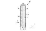
本実施形態に係る電極複合体は、図1に示すように、導電体層1と、導電体層1の一方の面1aに設けられた多孔質体層2とを備えている。
[First embodiment]
As shown in FIG. 1, the electrode assembly according to the present embodiment includes a conductor layer 1 and a porous body layer 2 provided on one surface 1 a of the conductor layer 1.

(導電体層)
電極複合体10における導電体層1は、導電性、酸素透過性及びプロトン透過性を有している。電極複合体10にこのような導電体層1を設けることで、導電体層1を正極として用いる場合には、後述する局部電池反応により生成した電子を触媒と外部回路110との間で導通させることが可能となる。つまり、後述するように、導電体層1を微生物燃料電池の正極として用いる場合、導電体層1には触媒が担持される。そして、外部回路110から導電体層1を通じて電子が触媒に移動し、触媒によって、酸素、水素イオン及び電子による酸素還元反応を進行させることが可能となる。また、導電体層1を微生物燃料電池の負極として用いる場合、嫌気性微生物の触媒作用により生成した電子を導電体層1と外部回路110との間で導通させることが可能となる。
(Conductor layer)
The conductor layer 1 in the electrode assembly 10 has conductivity, oxygen permeability, and proton permeability. By providing such a conductor layer 1 in the electrode composite 10, when the conductor layer 1 is used as a positive electrode, electrons generated by a local battery reaction described later are conducted between the catalyst and the external circuit 110. It becomes possible. That is, as will be described later, when the conductor layer 1 is used as a positive electrode of a microbial fuel cell, a catalyst is supported on the conductor layer 1. Then, electrons move from the external circuit 110 to the catalyst through the conductor layer 1, and the oxygen reduction reaction by oxygen, hydrogen ions and electrons can be advanced by the catalyst. Further, when the conductor layer 1 is used as the negative electrode of the microbial fuel cell, electrons generated by the catalytic action of anaerobic microorganisms can be conducted between the conductor layer 1 and the external circuit 110.

電極複合体10では、安定的な性能を確保するために、酸素及び水素イオンが導電体層1を効率よく透過して触媒に供給されることが好ましい。そのため、導電体層1は、面1bから反対側の面1aにかけて、酸素及び水素イオンが透過する細孔を多数有する多孔質体であることが好ましい。また、導電体層1の形状は、三次元のメッシュ状であることが特に好ましい。このようなメッシュ状であることにより、導電体層1に対し、高い酸素透過性及び導電性を付与することが可能となる。   In the electrode assembly 10, it is preferable that oxygen and hydrogen ions efficiently pass through the conductor layer 1 and be supplied to the catalyst in order to ensure stable performance. Therefore, the conductor layer 1 is preferably a porous body having a large number of pores through which oxygen and hydrogen ions pass from the surface 1b to the opposite surface 1a. The shape of the conductor layer 1 is particularly preferably a three-dimensional mesh. With such a mesh shape, high oxygen permeability and conductivity can be imparted to the conductor layer 1.

本実施形態において、導電体層1は、第一の表面11aと、第一の表面11aと反対側の第二の表面11bとを備えるシート状の多孔質基材11に対し、第一の表面11aから第二の表面11bに向かって導電性材料を設けることにより形成されている。つまり、導電体層1と多孔質体層2とを別個に作製し、それらを積層しているわけではなく、導電体層1及び多孔質体層2は単層の多孔質基材11から構成されている。このように、導電体層1と多孔質体層2とを多孔質基材11を基に形成することにより、導電体層1と多孔質体層2との間の剥離を防ぎ、機械的強度を高めることが可能となる。   In this embodiment, the conductor layer 1 has a first surface relative to a sheet-like porous substrate 11 having a first surface 11a and a second surface 11b opposite to the first surface 11a. It is formed by providing a conductive material from 11a toward the second surface 11b. That is, the conductor layer 1 and the porous body layer 2 are produced separately, and they are not laminated, but the conductor layer 1 and the porous body layer 2 are composed of a single-layer porous substrate 11. Has been. Thus, by forming the conductor layer 1 and the porous body layer 2 on the basis of the porous substrate 11, peeling between the conductor layer 1 and the porous body layer 2 is prevented, and the mechanical strength is increased. Can be increased.

導電体層1を構成する導電性材料は、高い導電性が確保できるならば特に限定されない。ただ、導電性材料は、アルミニウム、銅、ステンレス鋼、ニッケル及びチタンからなる群より選ばれる少なくとも一つの導電性金属からなることが好ましい。これらの導電性金属は、高い耐食性及び導電性を備えているため、導電体層1を構成する材料として好適に用いることができる。   The conductive material constituting the conductor layer 1 is not particularly limited as long as high conductivity can be secured. However, the conductive material is preferably made of at least one conductive metal selected from the group consisting of aluminum, copper, stainless steel, nickel and titanium. Since these conductive metals have high corrosion resistance and conductivity, they can be suitably used as a material constituting the conductor layer 1.

導電性材料は、炭素材料であってもよい。炭素材料としては、例えば、グラファイト、活性炭、カーボンブラック、バルカン(登録商標)XC−72R、アセチレンブラック、ファーネスブラック、デンカブラックなどのカーボンパウダーが挙げられる。また、炭素材料の例として、カーボンナノチューブ、カーボンナノホーン、カーボンナノクラスターのような微細構造物質も挙げられる。このような炭素材料も高い耐食性及び導電性を備えているため、導電体層1を構成する材料として好適に用いることができる。なお、上記導電性金属及び炭素材料は一種を単独で使用してもよく、二種以上を組み合わせて使用してもよい。   The conductive material may be a carbon material. Examples of the carbon material include carbon powders such as graphite, activated carbon, carbon black, Vulcan (registered trademark) XC-72R, acetylene black, furnace black, and Denka black. Examples of the carbon material include fine structure substances such as carbon nanotubes, carbon nanohorns, and carbon nanoclusters. Since such a carbon material also has high corrosion resistance and conductivity, it can be suitably used as a material constituting the conductor layer 1. In addition, the said conductive metal and carbon material may be used individually by 1 type, and may be used in combination of 2 or more type.

多孔質基材11は、酸素、水素イオン及び電解液70を透過する細孔を多数有するシートである。なお、多孔質基材11は、第一の表面11aから第二の表面11bにかけて連続した細孔を有していることが好ましい。これにより、酸素及び水素イオンが正極中の触媒に到達しやすくなり、酸素還元反応を促進することが可能となる。なお、多孔質基材11における細孔の孔径は酸素、水素イオン及び電解液70が透過できるならば特に限定されないが、例えば0.5μm以上であることが好ましい。多孔質基材11における細孔の孔径が0.5μm以上であることにより、酸素、水素イオン及び電解液70を十分に透過し、発電効率を高めることが可能となる。多孔質基材11における細孔の孔径の上限は特に限定されないが、例えば1.0mmとすることができる。多孔質基材11における細孔の孔径は、例えば水銀圧入法により測定することができる。   The porous substrate 11 is a sheet having a large number of pores that allow oxygen, hydrogen ions, and the electrolytic solution 70 to pass therethrough. The porous substrate 11 preferably has continuous pores from the first surface 11a to the second surface 11b. Thereby, oxygen and hydrogen ions easily reach the catalyst in the positive electrode, and the oxygen reduction reaction can be promoted. The pore diameter of the porous substrate 11 is not particularly limited as long as oxygen, hydrogen ions, and the electrolyte solution 70 can permeate, but is preferably 0.5 μm or more, for example. When the pore diameter of the porous substrate 11 is 0.5 μm or more, it is possible to sufficiently transmit oxygen, hydrogen ions, and the electrolytic solution 70 to increase power generation efficiency. Although the upper limit of the pore diameter of the pores in the porous substrate 11 is not particularly limited, it can be set to, for example, 1.0 mm. The pore diameter of the porous substrate 11 can be measured, for example, by a mercury intrusion method.

多孔質基材11の厚さt1は1.0mm〜50mmであることが好ましい。多孔質基材11の厚さt1が1.0mm〜50mmであることにより、電極複合体10に形成される多孔質体層2の厚さを大きくすることができるため、電解液70に含まれる好気性微生物が多孔質体層2の内部に侵入することを抑制できる。   The thickness t1 of the porous substrate 11 is preferably 1.0 mm to 50 mm. Since the thickness t <b> 1 of the porous substrate 11 is 1.0 mm to 50 mm, the thickness of the porous body layer 2 formed on the electrode assembly 10 can be increased. Aerobic microorganisms can be prevented from entering the porous body layer 2.

多孔質基材11は、導電体であってもよく、電気絶縁体であってもよい。ただ、多孔質基材11は電気絶縁体であることが好ましい。多孔質基材11が電気絶縁体であることにより、後述するように、電極複合体10を微生物燃料電池に用いた場合、イオン移動層30が不要となるため、微生物燃料電池の薄膜化及び電池構造の簡略化を図ることが可能となる。   The porous substrate 11 may be a conductor or an electrical insulator. However, the porous substrate 11 is preferably an electrical insulator. Since the porous base material 11 is an electrical insulator, as will be described later, when the electrode assembly 10 is used in a microbial fuel cell, the ion migration layer 30 is not required, and thus the microbial fuel cell is made thinner and the battery It is possible to simplify the structure.

多孔質基材11を構成する材料としては、例えば、ポリエチレン及びポリプロピレンなどの樹脂材料、アルミニウム、銅、ステンレス鋼、ニッケル及びチタンなどの導電性金属、並びにカーボンペーパー及びカーボンフェルトなどの炭素材料からなる群より選ばれる少なくとも一つを用いることができる。なお、多孔質基材11は、合成樹脂によって形成されていることが好ましい。合成樹脂からなることにより、電気絶縁性を容易に確保することが可能となる。   Examples of the material constituting the porous substrate 11 include resin materials such as polyethylene and polypropylene, conductive metals such as aluminum, copper, stainless steel, nickel and titanium, and carbon materials such as carbon paper and carbon felt. At least one selected from the group can be used. The porous substrate 11 is preferably formed of a synthetic resin. By comprising a synthetic resin, it is possible to easily ensure electrical insulation.

多孔質基材11としては、織布構造のシート、不織布構造のシート、及び連続発泡体構造のシートからなる群より選ばれる少なくとも一つを使用することができる。また、多孔質基材11は複数のシートを積層した積層体でもよい。ただ、多孔質基材11は不織布からなることが好ましい。多孔質基材11として、このような複数の細孔を有するシートを用いることにより、酸素及び水素イオンが移動しやすくなり、酸素還元反応の速度を高めることが可能となる。   As the porous substrate 11, at least one selected from the group consisting of a sheet having a woven fabric structure, a sheet having a nonwoven fabric structure, and a sheet having a continuous foam structure can be used. The porous substrate 11 may be a laminated body in which a plurality of sheets are laminated. However, the porous substrate 11 is preferably made of a nonwoven fabric. By using a sheet having such a plurality of pores as the porous substrate 11, oxygen and hydrogen ions can easily move and the rate of the oxygen reduction reaction can be increased.

上述のように、導電体層1は、多孔質基材11における第一の表面11aから第二の表面11bに向かって導電性材料を設けることにより形成されている。導電体層1の形成方法は特に限定されないが、例えば、導電性材料を含有するスラリーを塗工する方法や当該スラリーを印刷する方法、導電性材料を蒸着する方法等が適用できる。これらの方法を二種類以上組み合わせることにより、導電体層1を形成してもよい。   As described above, the conductor layer 1 is formed by providing a conductive material from the first surface 11 a to the second surface 11 b in the porous substrate 11. Although the formation method of the conductor layer 1 is not specifically limited, For example, the method of apply | coating the slurry containing an electroconductive material, the method of printing the said slurry, the method of vapor-depositing an electroconductive material, etc. are applicable. The conductor layer 1 may be formed by combining two or more of these methods.

なお、導電性材料は、結着剤を用いて多孔質基材11の表面及び細孔内部に保持されていてもよい。これにより、導電性材料が多孔質基材11の表面及び細孔内部から脱離し、導電性が低下することを抑制できる。このような結着剤としては、粒子同士を結着できれば特に限定されない。結着剤としては、例えばポリテトラフルオロエチレン(PTFE)、ポリフッ化ビニリデン(PVDF)、エチレン−プロピレン−ジエン共重合体(EPDM)及びナフィオンからなる群より選ばれる少なくとも一つを用いることが好ましい。   The conductive material may be held on the surface of the porous substrate 11 and inside the pores using a binder. Thereby, it can suppress that electroconductive material detach | desorbs from the surface of the porous base material 11, and the inside of a pore, and electroconductivity falls. Such a binder is not particularly limited as long as particles can be bound to each other. As the binder, for example, at least one selected from the group consisting of polytetrafluoroethylene (PTFE), polyvinylidene fluoride (PVDF), ethylene-propylene-diene copolymer (EPDM) and Nafion is preferably used.

(多孔質体層)
本実施形態に係る電極複合体10は、図1に示すように、導電体層1の一方の面1aに設けられた多孔質体層2を備えている。上述のように、導電体層1は、多孔質基材11における第一の表面11aから第二の表面11bに向かって導電性材料を設けることにより形成されている。そのため、多孔質基材11における導電体層1が設けられた以外の部分は多孔質体層2を構成する。
(Porous body layer)
As shown in FIG. 1, the electrode assembly 10 according to this embodiment includes a porous body layer 2 provided on one surface 1 a of the conductor layer 1. As described above, the conductor layer 1 is formed by providing a conductive material from the first surface 11 a to the second surface 11 b in the porous substrate 11. Therefore, a portion of the porous substrate 11 other than the conductor layer 1 provided constitutes the porous body layer 2.

電極複合体10において、多孔質体層2の厚さt2は、少なくとも多孔質基材11の厚さt1よりも小さい。そのため、多孔質体層2の厚さt2は0.5mm〜40mmであることが好ましい。多孔質体層2の厚さt2が0.5mm〜40mmであることにより、電解液70に含まれる好気性微生物が多孔質体層2の内部に侵入することを抑制することが可能となる。なお、多孔質体層2の厚さt2は、1.0mm〜40mmであることがより好ましく、1.5mm〜10mmであることがさらに好ましい。多孔質体層2の厚さt2がこの範囲内であることにより、好気性微生物が多孔質体層2の内部へ侵入することを抑制しつつも、水素イオンの透過率を高め、水素イオンを触媒へ効率的に到達させることが可能となる。   In the electrode assembly 10, the thickness t2 of the porous body layer 2 is at least smaller than the thickness t1 of the porous substrate 11. Therefore, the thickness t2 of the porous body layer 2 is preferably 0.5 mm to 40 mm. When the thickness t2 of the porous body layer 2 is 0.5 mm to 40 mm, it is possible to prevent the aerobic microorganisms contained in the electrolytic solution 70 from entering the inside of the porous body layer 2. The thickness t2 of the porous body layer 2 is more preferably 1.0 mm to 40 mm, and further preferably 1.5 mm to 10 mm. When the thickness t2 of the porous body layer 2 is within this range, the aerobic microorganisms are prevented from entering the inside of the porous body layer 2, and the hydrogen ion permeability is increased and the hydrogen ions are reduced. It is possible to efficiently reach the catalyst.

上述のように、多孔質体層2は多孔質基材11の一部分からなるものである。そのため、多孔質体層2は面2aから反対側の面2bに連続した細孔を有していることが好ましい。これにより、水素イオンが正極中の触媒に到達しやすくなり、酸素還元反応を促進することが可能となる。なお、多孔質基材11における細孔の孔径は水素イオン及び電解液70が透過できるならば特に限定されないが、例えば0.5μm以上であることが好ましい。   As described above, the porous body layer 2 is composed of a part of the porous substrate 11. Therefore, the porous body layer 2 preferably has continuous pores from the surface 2a to the opposite surface 2b. Thereby, it becomes easy for hydrogen ions to reach the catalyst in the positive electrode, and the oxygen reduction reaction can be promoted. The pore diameter of the porous substrate 11 is not particularly limited as long as hydrogen ions and the electrolyte solution 70 can permeate, but is preferably 0.5 μm or more, for example.

(撥水層)
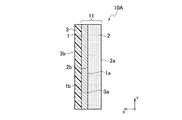
図2に示すように、電極複合体10は、導電体層1の面1bには撥水層3を設けてもよい。撥水層3は、撥水性を有しているため、導電体層1を微生物燃料電池の正極として用いた場合、廃水槽80の内部に保持された液相としての電解液70と気相90とを分離する。そして、撥水層3を設けることで、電解液70が気相90側に移動することを抑制できる。なお、ここでいう「分離」とは、物理的に遮断することをいう。
(Water repellent layer)
As shown in FIG. 2, the electrode assembly 10 may be provided with a water repellent layer 3 on the surface 1 b of the conductor layer 1. Since the water repellent layer 3 has water repellency, when the conductor layer 1 is used as the positive electrode of the microbial fuel cell, the electrolytic solution 70 and the gas phase 90 as the liquid phase retained in the waste water tank 80 are used. And are separated. And by providing the water repellent layer 3, it can suppress that the electrolyte solution 70 moves to the gaseous-phase 90 side. In addition, "separation" here means physical interruption | blocking.

撥水層3は、酸素を含む気相90と接触しており、気相90中の酸素を拡散する。そして、撥水層3は、導電体層1の面1bに対し酸素を略均一に供給している。そのため、撥水層3は、当該酸素を拡散できるように多孔質体であることが好ましい。なお、撥水層3が撥水性を有するため、結露等により多孔質体の細孔が閉塞し、酸素の拡散性が低下することを抑制できる。また、撥水層3の内部に電解液70が染み込み難いため、撥水層3における気相90と接触する面3bから導電体層1と対向する面3aにかけて、酸素を効率的に流通させることが可能となる。   The water repellent layer 3 is in contact with the gas phase 90 containing oxygen, and diffuses oxygen in the gas phase 90. The water repellent layer 3 supplies oxygen substantially uniformly to the surface 1 b of the conductor layer 1. Therefore, the water repellent layer 3 is preferably a porous body so that the oxygen can be diffused. In addition, since the water repellent layer 3 has water repellency, it can suppress that the pore of a porous body obstruct | occludes by dew condensation etc., and the diffusibility of oxygen falls. In addition, since the electrolytic solution 70 hardly penetrates into the water repellent layer 3, oxygen can be efficiently circulated from the surface 3 b in contact with the gas phase 90 in the water repellent layer 3 to the surface 3 a facing the conductor layer 1. Is possible.

撥水層3は、織布又は不織布によりシート状に形成されていることが好ましい。また、撥水層3を構成する材料は、撥水性を有し、気相90中の酸素を拡散できれば特に限定されない。撥水層3を構成する材料としては、例えば、ポリエチレン、ポリプロピレン、ポリブタジエン、ナイロン、ポリテトラフルオロエチレン(PTFE)、エチルセルロース、ポリ−4−メチルペンテン−1、ブチルゴム及びポリジメチルシロキサン(PDMS)からなる群より選ばれる少なくとも一つを使用することができる。これらの材料は多孔質体を形成しやすく、さらに撥水性も高いため、細孔の閉塞を抑制してガス拡散性を向上させることができる。なお、撥水層3は、撥水層3及び導電体層1の積層方向Xに複数の貫通孔を有することが好ましい。   The water repellent layer 3 is preferably formed in a sheet shape from a woven fabric or a non-woven fabric. The material constituting the water repellent layer 3 is not particularly limited as long as it has water repellency and can diffuse oxygen in the gas phase 90. Examples of the material constituting the water repellent layer 3 include polyethylene, polypropylene, polybutadiene, nylon, polytetrafluoroethylene (PTFE), ethyl cellulose, poly-4-methylpentene-1, butyl rubber, and polydimethylsiloxane (PDMS). At least one selected from the group can be used. Since these materials are easy to form a porous body and also have high water repellency, they can suppress clogging of pores and improve gas diffusibility. The water repellent layer 3 preferably has a plurality of through holes in the stacking direction X of the water repellent layer 3 and the conductor layer 1.

撥水層3は撥水性を高めるために、必要に応じて撥水剤を用いて撥水処理を施してもよい。具体的には、撥水層3を構成する多孔質体にポリテトラフルオロエチレン等の撥水剤を付着させ、撥水性を向上させてもよい。   The water repellent layer 3 may be subjected to a water repellent treatment using a water repellent as necessary in order to increase water repellency. Specifically, a water repellent such as polytetrafluoroethylene may be attached to the porous body constituting the water repellent layer 3 to improve water repellency.

図2に示す電極複合体10において、導電体層1の面1bに効率的に酸素を供給するために、撥水層3は、接着剤を介して導電体層1と接合していることが好ましい。つまり、撥水層3の面3aは、対向する導電体層1の面1bと接着剤を介して接合していることが好ましい。これにより、導電体層1の面1bに対し、拡散した酸素が直接供給され、酸素還元反応を効率的に行うことができる。接着剤は、撥水層3と導電体層1との間の接着性を確保する観点から、撥水層3と導電体層1との間の少なくとも一部に設けられていることが好ましい。ただ、撥水層3と導電体層1との間の接着性を高め、長期間に亘り安定的に酸素を導電体層1に供給する観点から、接着剤は撥水層3と導電体層1との間の全面に設けられていることがより好ましい。   In the electrode assembly 10 shown in FIG. 2, in order to efficiently supply oxygen to the surface 1b of the conductor layer 1, the water repellent layer 3 is bonded to the conductor layer 1 through an adhesive. preferable. That is, it is preferable that the surface 3a of the water repellent layer 3 is bonded to the surface 1b of the opposing conductor layer 1 via an adhesive. Thereby, the diffused oxygen is directly supplied to the surface 1b of the conductor layer 1, and the oxygen reduction reaction can be performed efficiently. The adhesive is preferably provided on at least a part between the water repellent layer 3 and the conductor layer 1 from the viewpoint of securing the adhesiveness between the water repellent layer 3 and the conductor layer 1. However, from the viewpoint of improving the adhesiveness between the water repellent layer 3 and the conductor layer 1 and supplying oxygen to the conductor layer 1 stably over a long period of time, the adhesive is made of the water repellent layer 3 and the conductor layer. It is more preferable that it is provided on the entire surface between the two.

接着剤としては酸素透過性を有するものが好ましく、ポリメチルメタクリレート、メタクリル酸−スチレン共重合体、スチレン−ブタジエンゴム、ブチルゴム、ニトリルゴム、クロロプレンゴム及びシリコーンからなる群より選ばれる少なくとも一つを含む樹脂を用いることができる。   The adhesive preferably has oxygen permeability, and includes at least one selected from the group consisting of polymethyl methacrylate, methacrylic acid-styrene copolymer, styrene-butadiene rubber, butyl rubber, nitrile rubber, chloroprene rubber, and silicone. Resin can be used.

(触媒)
導電体層1を正極として用いる場合には、導電体層1には、触媒が担持されていることが好ましい。また、当該触媒は酸素還元触媒であることが好ましい。触媒が酸素還元触媒であることにより、導電体層1へ供給された酸素と水素イオンとの反応速度をより高め、酸素の還元反応効率を向上させることができるので、より効率的な液体処理を実現することが可能となる。
(catalyst)
When the conductor layer 1 is used as a positive electrode, the conductor layer 1 preferably supports a catalyst. The catalyst is preferably an oxygen reduction catalyst. Since the catalyst is an oxygen reduction catalyst, the reaction rate between oxygen and hydrogen ions supplied to the conductor layer 1 can be further increased, and the reduction reaction efficiency of oxygen can be improved. It can be realized.

触媒は、導電体層1の表面に担持されていることが好ましい。つまり、触媒は、導電体層1における撥水層3側の面1bに担持されていてもよく、さらに導電体層1の内部に担持されていてもよい。そして、酸素、水素イオン及び電子による酸素還元反応を促進する観点から、導電体層1と触媒とは電気的に接続していることが好ましく、導電体層1と触媒とが接触していることが好ましい。   The catalyst is preferably supported on the surface of the conductor layer 1. That is, the catalyst may be supported on the surface 1b of the conductive layer 1 on the water repellent layer 3 side, and may be further supported on the inside of the conductive layer 1. And from the viewpoint of promoting the oxygen reduction reaction by oxygen, hydrogen ions and electrons, the conductor layer 1 and the catalyst are preferably electrically connected, and the conductor layer 1 and the catalyst are in contact with each other. Is preferred.

触媒は、結着剤を用いて導電体層1の表面及び細孔内部に担持されていてもよい。これにより、触媒が導電体層1の表面及び細孔内部から脱離し、酸素還元特性が低下することを抑制できる。このような結着剤としては、粒子同士を結着できれば特に限定されない。結着剤としては、例えばポリテトラフルオロエチレン、ポリフッ化ビニリデン、エチレン−プロピレン−ジエン共重合体及びナフィオンからなる群より選ばれる少なくとも一つを用いることが好ましい。   The catalyst may be supported on the surface of the conductor layer 1 and inside the pores using a binder. Thereby, it can suppress that a catalyst detach | desorbs from the surface of the conductor layer 1, and the inside of a pore, and an oxygen reduction characteristic falls. Such a binder is not particularly limited as long as particles can be bound to each other. As the binder, for example, at least one selected from the group consisting of polytetrafluoroethylene, polyvinylidene fluoride, an ethylene-propylene-diene copolymer, and Nafion is preferably used.

酸素還元触媒は、金属原子がドープされている炭素系材料であることが好ましい。金属原子としては特に限定されないが、チタン、バナジウム、クロム、マンガン、鉄、コバルト、ニッケル、銅、ジルコニウム、ニオブ、モリブデン、ルテニウム、ロジウム、パラジウム、銀、ハフニウム、タンタル、タングステン、レニウム、オスミウム、イリジウム、白金、及び金からなる群より選ばれる少なくとも一種の金属の原子であることが好ましい。この場合、炭素系材料が、特に酸素還元反応を促進させるための触媒として優れた性能を発揮する。炭素系材料が含有する金属原子の量は、炭素系材料が優れた触媒性能を有するように適宜設定すればよい。   The oxygen reduction catalyst is preferably a carbon-based material doped with metal atoms. Although it does not specifically limit as a metal atom, Titanium, vanadium, chromium, manganese, iron, cobalt, nickel, copper, zirconium, niobium, molybdenum, ruthenium, rhodium, palladium, silver, hafnium, tantalum, tungsten, rhenium, osmium, iridium It is preferably an atom of at least one metal selected from the group consisting of platinum, and gold. In this case, the carbon-based material exhibits excellent performance as a catalyst for promoting the oxygen reduction reaction. What is necessary is just to set suitably the quantity of the metal atom which carbonaceous material contains so that carbonaceous material may have the outstanding catalyst performance.

炭素系材料には、更に窒素、ホウ素、硫黄及びリンから選択される一種以上の非金属原子がドープされていることが好ましい。炭素系材料にドープされている非金属原子の量も、炭素系材料が優れた触媒性能を有するように適宜設定すればよい。   The carbon-based material is preferably further doped with one or more nonmetallic atoms selected from nitrogen, boron, sulfur and phosphorus. What is necessary is just to set suitably the quantity of the nonmetallic atom doped by the carbonaceous material so that carbonaceous material may have the outstanding catalyst performance.

炭素系材料は、例えばグラファイト及び無定形炭素等の炭素源原料をベースとし、この炭素源原料に金属原子と、窒素、ホウ素、硫黄及びリンから選択される一種以上の非金属原子とをドープすることで得られる。   The carbon-based material is based on a carbon source material such as graphite and amorphous carbon, for example, and the carbon source material is doped with a metal atom and one or more non-metal atoms selected from nitrogen, boron, sulfur and phosphorus. Can be obtained.

炭素系材料にドープされている金属原子と非金属原子との組み合わせは、適宜選択される。特に、非金属原子が窒素を含み、金属原子が鉄を含むことが好ましい。この場合、炭素系材料は、特に優れた触媒活性を有することができる。なお、非金属原子が窒素のみであってもよい。また、金属原子が鉄のみであってもよい。   A combination of a metal atom and a nonmetal atom doped in the carbon-based material is appropriately selected. In particular, it is preferable that the nonmetallic atom contains nitrogen and the metallic atom contains iron. In this case, the carbonaceous material can have a particularly excellent catalytic activity. The nonmetallic atom may be only nitrogen. Further, the metal atom may be only iron.

非金属原子が窒素を含み、金属原子がコバルトとマンガンとのうち少なくとも一方を含んでもよい。この場合も、炭素系材料は特に優れた触媒活性を有することができる。なお、非金属原子が窒素のみであってもよい。また、金属原子がコバルトのみ、マンガンのみ、あるいはコバルト及びマンガンのみであってもよい。   The nonmetallic atom may contain nitrogen, and the metallic atom may contain at least one of cobalt and manganese. Also in this case, the carbon-based material can have a particularly excellent catalytic activity. The nonmetallic atom may be only nitrogen. Further, the metal atom may be only cobalt, only manganese, or only cobalt and manganese.

酸素還元触媒として構成される炭素系材料は、次のように調製することができる。まず、例えば窒素、ホウ素、硫黄及びリンからなる群より選ばれる少なくとも一種の非金属を含む非金属化合物と、金属化合物と、炭素源原料とを含有する混合物を準備する。そして、この混合物を、800℃以上1000℃以下の温度で、45秒以上600秒未満加熱する。これにより、酸素還元触媒として構成される炭素系材料を得ることができる。   A carbon-based material configured as an oxygen reduction catalyst can be prepared as follows. First, for example, a mixture containing a nonmetallic compound containing at least one nonmetal selected from the group consisting of nitrogen, boron, sulfur, and phosphorus, a metal compound, and a carbon source material is prepared. And this mixture is heated at the temperature of 800 degreeC or more and 1000 degrees C or less for 45 second or more and less than 600 second. Thereby, the carbonaceous material comprised as an oxygen reduction catalyst can be obtained.

炭素源原料としては、上述の通り、例えばグラファイト又は無定形炭素を使用することができる。さらに、金属化合物としては、炭素源原料にドープされる非金属原子と配位結合し得る金属原子を含む化合物であれば、特に制限されない。金属化合物は、例えば金属の塩化物、硝酸塩、硫酸塩、臭化物、ヨウ化物、フッ化物などのような無機金属塩;酢酸塩などの有機金属塩;無機金属塩の水和物;及び有機金属塩の水和物からなる群より選ばれる少なくとも一種を使用することができる。例えばグラファイトに鉄がドープされる場合には、金属化合物は塩化鉄(III)を含有することが好ましい。また、グラファイトにコバルトがドープされる場合には、金属化合物は塩化コバルトを含有することが好ましい。また、炭素源原料にマンガンがドープされる場合には、金属化合物は酢酸マンガンを含有することが好ましい。金属化合物の使用量は、例えば炭素源原料に対する金属化合物中の金属原子の割合が5〜30質量%の範囲内となるように設定することが好ましく、更にこの割合が5〜20質量%の範囲内となるように設定することがより好ましい。   As the carbon source material, for example, graphite or amorphous carbon can be used as described above. Further, the metal compound is not particularly limited as long as it is a compound containing a metal atom capable of coordinating with a nonmetal atom doped in the carbon source material. Metal compounds include, for example, metal chlorides, nitrates, sulfates, bromides, iodides, fluorides, etc .; inorganic metal salts such as acetates; inorganic metal salt hydrates; and organic metal salts At least one selected from the group consisting of hydrates can be used. For example, when graphite is doped with iron, the metal compound preferably contains iron (III) chloride. Moreover, when graphite is doped with cobalt, the metal compound preferably contains cobalt chloride. When the carbon source material is doped with manganese, the metal compound preferably contains manganese acetate. The amount of the metal compound used is preferably set so that, for example, the ratio of the metal atom in the metal compound to the carbon source material is in the range of 5 to 30% by mass, and the ratio is in the range of 5 to 20% by mass. It is more preferable to set so as to be within.

非金属化合物は、上記の通り、窒素、ホウ素、硫黄及びリンからなる群より選ばれる少なくとも一種の非金属の化合物であることが好ましい。非金属化合物としては、例えば、ペンタエチレンヘキサミン、エチレンジアミン、テトラエチレンペンタミン、トリエチレンテトラミン、エチレンジアミン、オクチルボロン酸、1,2−ビス(ジエチルホスフィノエタン)、亜リン酸トリフェニル、ベンジルジサルフィドからなる群より選ばれる少なくとも一種の化合物を使用することができる。非金属化合物の使用量は、炭素源原料への非金属原子のドープ量に応じて適宜設定される。非金属化合物の使用量は、金属化合物中の金属原子と、非金属化合物中の非金属原子とのモル比が、1:1〜1:2の範囲内となるように設定ことが好ましく、1:1.5〜1:1.8の範囲内となるように設定することがより好ましい。   As described above, the nonmetallic compound is preferably at least one nonmetallic compound selected from the group consisting of nitrogen, boron, sulfur and phosphorus. Non-metallic compounds include, for example, pentaethylenehexamine, ethylenediamine, tetraethylenepentamine, triethylenetetramine, ethylenediamine, octylboronic acid, 1,2-bis (diethylphosphinoethane), triphenyl phosphite, benzyldisal At least one compound selected from the group consisting of fido can be used. The amount of the nonmetallic compound used is appropriately set according to the amount of the nonmetallic atom doped into the carbon source material. The amount of the nonmetallic compound used is preferably set so that the molar ratio of the metal atom in the metal compound to the nonmetallic atom in the nonmetallic compound is within the range of 1: 1 to 1: 2. : It is more preferable to set it within the range of 1.5 to 1: 1.8.

酸素還元触媒として構成される炭素系材料を調製する際の、非金属化合物と金属化合物と炭素源原料とを含有する混合物は、例えば次のようにして得られる。まず炭素源原料と金属化合物と非金属化合物とを混合し、更に必要に応じてエタノール等の溶媒を加えて全量を調整する。これらを更に超音波分散法により分散させる。続いて、これらを適宜の温度(例えば60℃)で加熱した後に、混合物を乾燥して溶媒を除去する。これにより、非金属化合物と金属化合物と炭素源原料とを含有する混合物が得られる。   A mixture containing a nonmetallic compound, a metal compound, and a carbon source raw material when preparing a carbon-based material configured as an oxygen reduction catalyst is obtained, for example, as follows. First, a carbon source material, a metal compound, and a nonmetal compound are mixed, and if necessary, a solvent such as ethanol is added to adjust the total amount. These are further dispersed by an ultrasonic dispersion method. Subsequently, after heating them at an appropriate temperature (for example, 60 ° C.), the mixture is dried to remove the solvent. Thereby, the mixture containing a nonmetallic compound, a metal compound, and a carbon source raw material is obtained.

次に、得られた混合物を、例えば還元性雰囲気下又は不活性ガス雰囲気下で加熱する。これにより、炭素源原料に非金属原子がドープされ、さらに非金属原子と金属原子とが配位結合することで金属原子もドープされる。加熱温度は800℃以上1000℃以下の範囲内であることが好ましく、加熱時間は45秒以上600秒未満の範囲内であることが好ましい。加熱時間が短時間であるため、炭素系材料が効率よく製造され、しかも炭素系材料の触媒活性が更に高くなる。なお、加熱処理における、加熱開始時の混合物の昇温速度は、50℃/s以上であることが好ましい。このような急速加熱は、炭素系材料の触媒活性を更に向上させる。   Next, the obtained mixture is heated, for example, under a reducing atmosphere or an inert gas atmosphere. Thereby, a non-metallic atom is doped to a carbon source raw material, and also a metallic atom is doped by the coordinate bond of a non-metallic atom and a metallic atom. The heating temperature is preferably in the range of 800 ° C. to 1000 ° C., and the heating time is preferably in the range of 45 seconds to less than 600 seconds. Since the heating time is short, the carbon-based material is efficiently produced, and the catalytic activity of the carbon-based material is further increased. In the heat treatment, the temperature rising rate of the mixture at the start of heating is preferably 50 ° C./s or more. Such rapid heating further improves the catalytic activity of the carbon-based material.

また、炭素系材料を、更に酸洗浄してもよい。例えば炭素系材料を、純水中、ホモジナイザーで30分間分散させ、その後この炭素系材料を2M硫酸中に入れて、80℃で3時間攪拌してもよい。この場合、炭素系材料からの金属成分の溶出が抑えられる。   Further, the carbon-based material may be further subjected to acid cleaning. For example, the carbon-based material may be dispersed in pure water with a homogenizer for 30 minutes, and then the carbon-based material may be placed in 2M sulfuric acid and stirred at 80 ° C. for 3 hours. In this case, elution of the metal component from the carbon-based material can be suppressed.

このような製造方法により、不活性金属化合物及び金属結晶の含有量が著しく低く、かつ、導電性の高い炭素系材料が得られる。   By such a production method, a carbon-based material having a significantly low content of inert metal compounds and metal crystals and high conductivity can be obtained.

(封止材料)
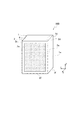
電極複合体10における導電体層1の側面1e及び多孔質体層2の側面2eは、封止材料4によって封止されていることが好ましい。具体的には、図3に示す電極複合体10Bのように、導電体層1における上面1d,側面1e及び底面1fは封止材料4により封止されていることが好ましい。さらに、多孔質体層2における面2aの外周部2c、上面2d,側面2e及び底面2fも封止材料4を用いて封止されていることが好ましい。このように、導電体層1及び多孔質体層2の上面、側面及び底面が封止材料4によって封止されていることにより、上面、側面及び底面から内部に好気性微生物が侵入することを抑制できる。その結果、好気性微生物が電極複合体10Bの内部で増殖することを防ぐことが可能となる。なお、図3では、導電体層1における上面1d,側面1e及び底面1f並びに多孔質体層2における面2aの外周部2c、上面2d,側面2e及び底面2fが封止材料4によって封止されている。ただ、好気性微生物の侵入を抑制するためには、少なくとも導電体層1の側面1e及び多孔質体層2の側面2eが封止材料4によって封止されていればよい。
(Sealing material)
The side surface 1 e of the conductor layer 1 and the side surface 2 e of the porous body layer 2 in the electrode assembly 10 are preferably sealed with a sealing material 4. Specifically, it is preferable that the upper surface 1 d, the side surface 1 e, and the bottom surface 1 f of the conductor layer 1 are sealed with the sealing material 4 as in the electrode assembly 10 </ b> B illustrated in FIG. 3. Furthermore, it is preferable that the outer peripheral portion 2 c, the upper surface 2 d, the side surface 2 e, and the bottom surface 2 f of the surface 2 a in the porous body layer 2 are also sealed with the sealing material 4. As described above, the upper surface, the side surface, and the bottom surface of the conductor layer 1 and the porous body layer 2 are sealed with the sealing material 4, so that the aerobic microorganisms enter the inside from the upper surface, the side surface, and the bottom surface. Can be suppressed. As a result, it becomes possible to prevent aerobic microorganisms from growing inside the electrode assembly 10B. In FIG. 3, the upper surface 1 d, the side surface 1 e and the bottom surface 1 f of the conductor layer 1 and the outer peripheral portion 2 c, the upper surface 2 d, the side surface 2 e and the bottom surface 2 f of the porous body layer 2 are sealed with the sealing material 4. ing. However, in order to suppress the invasion of aerobic microorganisms, at least the side surface 1e of the conductor layer 1 and the side surface 2e of the porous body layer 2 may be sealed with the sealing material 4.

封止材料4は、少なくとも好気性微生物が通過しない材料からなることが好ましく、例えば、エポキシ樹脂、ポリメチルメタクリレート、メタクリル酸−スチレン共重合体、スチレン−ブタジエンゴム、ブチルゴム、ニトリルゴム、クロロプレンゴム及びシリコーンからなる群より選ばれる少なくとも一つを含む樹脂を用いることができる。   The sealing material 4 is preferably made of a material that does not allow at least aerobic microorganisms to pass through. For example, epoxy resin, polymethyl methacrylate, methacrylic acid-styrene copolymer, styrene-butadiene rubber, butyl rubber, nitrile rubber, chloroprene rubber, and A resin containing at least one selected from the group consisting of silicones can be used.

本実施形態の電極複合体10,10Aにおける多孔質体層2の作用について説明する。図4に示すように、電極複合体10Aの導電体層1を微生物燃料電池の正極として用いた場合、電極複合体10の導電体層1及び多孔質体層2が電解液70に浸漬され、撥水層3の面3bの少なくとも一部が気相90に露出する。そして、気相90に露出した撥水層3を透過して導電体層1に酸素が到達するため、多孔質体層2が存在しない場合には、電解液70中の好気性微生物は導電体層1を通過して、導電体層1と撥水層3との界面近傍で増殖してしまう。その結果、導電体層1と撥水層3との界面近傍で好気性微生物により酸素が消費されてしまうため、導電体層1に担持された触媒に酸素が十分に供給されず、酸素還元反応が生じ難くなってしまう。   The effect | action of the porous body layer 2 in the electrode composites 10 and 10A of this embodiment is demonstrated. As shown in FIG. 4, when the conductor layer 1 of the electrode composite 10A is used as the positive electrode of the microbial fuel cell, the conductor layer 1 and the porous body layer 2 of the electrode composite 10 are immersed in the electrolytic solution 70, At least a part of the surface 3 b of the water repellent layer 3 is exposed to the gas phase 90. Since oxygen reaches the conductor layer 1 through the water-repellent layer 3 exposed in the gas phase 90, the aerobic microorganism in the electrolytic solution 70 is a conductor when the porous body layer 2 is not present. It passes through the layer 1 and grows in the vicinity of the interface between the conductor layer 1 and the water repellent layer 3. As a result, oxygen is consumed by aerobic microorganisms in the vicinity of the interface between the conductor layer 1 and the water repellent layer 3, so that oxygen is not sufficiently supplied to the catalyst supported on the conductor layer 1, and the oxygen reduction reaction It becomes difficult to occur.

これに対し、導電体層1に多孔質体層2を設けた場合、電解液70中には好気性微生物の餌となる有機物が含まれるため、図4に示すように、多孔質体層2における電解液70中に露出した面2aには、微生物膜12が形成される。つまり、好気性微生物が有機物を消費して繁殖し、多孔質体層2の面2aに、好気性微生物が集合してなる微生物膜12が形成される。好気性微生物は、酸素が供給される気相90側へ進行しようするが、微生物膜12中の好気性微生物によって有機物は消費され、多孔質体層2の内部に侵入する有機物は減少してしまう。さらに、多孔質体層2の厚さを大きくすることにより、有機物が導電体層1側へ移動し難くなり、導電体層1と多孔質体層2の界面よりも導電体層1側では好気性微生物が増殖できなくなる。その結果、導電体層1と撥水層3との界面近傍で好気性微生物が増殖されないことから、好気性微生物による酸素消費が抑制され、導電体層1に担持された触媒に酸素を十分に供給されるため、効果的に酸素還元反応を行うことが可能となる。   On the other hand, when the porous body layer 2 is provided on the conductor layer 1, the electrolyte 70 contains an organic substance serving as a bait for aerobic microorganisms. Therefore, as shown in FIG. A microbial membrane 12 is formed on the surface 2a exposed in the electrolytic solution 70 in FIG. That is, aerobic microorganisms consume organic matter and propagate, and a microbial membrane 12 formed by aerobic microorganisms gathering on the surface 2 a of the porous body layer 2 is formed. The aerobic microorganisms proceed to the gas phase 90 side to which oxygen is supplied. However, the organic substances are consumed by the aerobic microorganisms in the microorganism film 12, and the organic substances entering the porous body layer 2 are reduced. . Furthermore, by increasing the thickness of the porous body layer 2, it becomes difficult for organic substances to move to the conductor layer 1 side, which is preferable on the conductor layer 1 side than the interface between the conductor layer 1 and the porous body layer 2. Aerobic microorganisms cannot grow. As a result, since aerobic microorganisms are not grown near the interface between the conductor layer 1 and the water repellent layer 3, oxygen consumption by the aerobic microorganisms is suppressed, and oxygen is sufficiently supplied to the catalyst supported on the conductor layer 1. Since it is supplied, it is possible to effectively perform an oxygen reduction reaction.

また、電極複合体10の導電体層1を微生物燃料電池の負極として用いた場合、電極複合体10の導電体層1及び多孔質体層2が電解液70に浸漬される。さらに、多孔質体層2の面2aに正極が積層され、正極における電極複合体10側の面と反対側の面の少なくとも一部が気相90に露出する。そして、気相90から正極に酸素が到達するため、多孔質体層2が存在しない場合には、電解液70中の好気性微生物は導電体層1を通過して、正極で増殖してしまう。その結果、正極で好気性微生物により酸素が消費されてしまうため、正極に担持された触媒に酸素が十分に供給されず、酸素還元反応が生じ難くなってしまう。   When the conductor layer 1 of the electrode assembly 10 is used as the negative electrode of the microbial fuel cell, the conductor layer 1 and the porous body layer 2 of the electrode assembly 10 are immersed in the electrolytic solution 70. Further, the positive electrode is laminated on the surface 2 a of the porous body layer 2, and at least a part of the surface of the positive electrode opposite to the surface on the electrode composite 10 side is exposed to the gas phase 90. And since oxygen reaches | attains the positive electrode from the gaseous phase 90, when the porous body layer 2 does not exist, the aerobic microorganisms in the electrolyte solution 70 will pass through the conductor layer 1, and will proliferate on a positive electrode. . As a result, oxygen is consumed by the aerobic microorganisms at the positive electrode, so that oxygen is not sufficiently supplied to the catalyst supported on the positive electrode, and the oxygen reduction reaction hardly occurs.

これに対し、導電体層1に多孔質体層2を設けた場合、図5に示すように、導電体層1における電解液70中に露出した面1bには、微生物膜12が形成される。好気性微生物は、酸素が供給される正極側へ進行しようするが、微生物膜12中の好気性微生物によって有機物は消費され、導電体層1及び多孔質体層2の内部に侵入する有機物は減少してしまう。さらに、多孔質体層2の厚さを大きくすることにより、有機物が正極側へ移動し難くなり、正極で好気性微生物が増殖できなくなる。その結果、好気性微生物による酸素消費が抑制され、正極に担持された触媒に酸素を十分に供給されるため、効果的に酸素還元反応を行うことが可能となる。   On the other hand, when the porous body layer 2 is provided on the conductor layer 1, the microbial membrane 12 is formed on the surface 1b of the conductor layer 1 exposed in the electrolytic solution 70 as shown in FIG. . The aerobic microorganisms proceed to the positive electrode side to which oxygen is supplied, but organic substances are consumed by the aerobic microorganisms in the microbial film 12, and the organic substances entering the conductor layer 1 and the porous body layer 2 are reduced. Resulting in. Furthermore, by increasing the thickness of the porous body layer 2, it becomes difficult for organic substances to move to the positive electrode side, and aerobic microorganisms cannot grow on the positive electrode. As a result, oxygen consumption by aerobic microorganisms is suppressed, and oxygen is sufficiently supplied to the catalyst supported on the positive electrode, so that an oxygen reduction reaction can be effectively performed.

このように、本実施形態に係る電極複合体10は、第一の表面11aと、第一の表面11aと反対側の第二の表面11bとを備える、シート状の多孔質基材11を有する。さらに、電極複合体10は、多孔質基材11の厚さ方向Xにおいて、第一の表面11aから第二の表面11bに向かって多孔質基材11の一部に設けられた第一の導電体層(導電体層1)を有する。このような構成により、電極複合体10の内部で好気性微生物が増殖されないことから、好気性微生物による酸素消費が抑制される。そのため、電極複合体10を用いた微生物燃料電池は発電性能の低下が抑制され、安定的に電気エネルギーを生産することが可能となる。   As described above, the electrode assembly 10 according to this embodiment includes the sheet-like porous substrate 11 including the first surface 11a and the second surface 11b opposite to the first surface 11a. . Furthermore, the electrode assembly 10 includes a first conductive material provided in a part of the porous substrate 11 from the first surface 11a toward the second surface 11b in the thickness direction X of the porous substrate 11. It has a body layer (conductor layer 1). With such a configuration, since aerobic microorganisms are not grown inside the electrode assembly 10, oxygen consumption by the aerobic microorganisms is suppressed. For this reason, the microbial fuel cell using the electrode assembly 10 is prevented from being deteriorated in power generation performance, and can stably produce electric energy.

[第二実施形態]
次に、第二実施形態に係る電極複合体について、図面に基づき詳細に説明する。なお、第一実施形態の電極複合体と同一構成には同一符号を付し、重複する説明は省略する。
[Second Embodiment]
Next, the electrode assembly according to the second embodiment will be described in detail based on the drawings. In addition, the same code | symbol is attached | subjected to the same structure as the electrode composite_body | complex of 1st embodiment, and the overlapping description is abbreviate | omitted.

本実施形態の電極複合体10Cは、図6に示すように、第一の表面11aと、第一の表面11aと反対側の第二の表面11bとを備える、シート状の多孔質基材11を有する。また、電極複合体10Cは、多孔質基材11の厚さ方向Xにおいて、第一の表面11aから第二の表面11bに向かって多孔質基材11の一部に設けられた第一の導電体層1を有する。さらに電極複合体10Cは、多孔質基材11の厚さ方向Xにおいて、第二の表面11bから第一の表面11aに向かって多孔質基材11の一部に設けられた第二の導電体層5を有する。   As shown in FIG. 6, the electrode assembly 10 </ b> C of the present embodiment includes a first surface 11 a and a sheet-like porous substrate 11 including a second surface 11 b opposite to the first surface 11 a. Have In addition, the electrode assembly 10 </ b> C is a first conductive material provided in a part of the porous substrate 11 from the first surface 11 a toward the second surface 11 b in the thickness direction X of the porous substrate 11. It has a body layer 1. Furthermore, the electrode assembly 10C is a second conductor provided on a part of the porous substrate 11 from the second surface 11b toward the first surface 11a in the thickness direction X of the porous substrate 11. Layer 5 is included.

本実施形態の電極複合体10Cは、第一の表面11a側に第一の導電体層1を設け、第二の表面11b側に第二の導電体層5を設けている。そして、第一の導電体層1と第二の導電体層5との間には、多孔質体層2が介在している。そのため、多孔質体層2が電気絶縁体からなる場合には、第一の導電体層1と第二の導電体層5との間の短絡を防ぐことができるため、第一の導電体層1と第二の導電体層5のいずれか一方を正極とし、他方を負極とすることができる。   In the electrode assembly 10C of the present embodiment, the first conductor layer 1 is provided on the first surface 11a side, and the second conductor layer 5 is provided on the second surface 11b side. A porous body layer 2 is interposed between the first conductor layer 1 and the second conductor layer 5. Therefore, when the porous body layer 2 is made of an electrical insulator, a short circuit between the first conductor layer 1 and the second conductor layer 5 can be prevented, so that the first conductor layer Either one of the first and second conductor layers 5 can be a positive electrode, and the other can be a negative electrode.

第一実施形態と同様に、第一の導電体層1は、多孔質基材11に対し、第一の表面11aから第二の表面11bに向かって導電性材料を設けることにより形成される。また、第二の導電体層5は、第二の表面11bから第一の表面11aに向かって導電性材料を設けることにより形成される。つまり、第一の導電体層1、第二の導電体層5及び多孔質体層2を別個に作製し、それらを積層しているわけではなく、第一の導電体層1、第二の導電体層5及び多孔質体層2は単層の多孔質基材11から構成されている。このように、第一の導電体層1、第二の導電体層5及び多孔質体層2を、多孔質基材11を基に形成することにより、各層の間の剥離を防ぎ、機械的強度を高めることが可能となる。   Similar to the first embodiment, the first conductor layer 1 is formed by providing a conductive material on the porous substrate 11 from the first surface 11a toward the second surface 11b. The second conductor layer 5 is formed by providing a conductive material from the second surface 11b toward the first surface 11a. That is, the first conductor layer 1, the second conductor layer 5, and the porous body layer 2 are produced separately and are not laminated, but the first conductor layer 1, the second conductor layer 2 The conductor layer 5 and the porous body layer 2 are composed of a single layer porous substrate 11. In this way, the first conductor layer 1, the second conductor layer 5, and the porous body layer 2 are formed on the basis of the porous base material 11, thereby preventing separation between the layers, and mechanically. The strength can be increased.

電極複合体10Cにおいて、多孔質基材11は電気絶縁体であることが好ましい。これにより、多孔質体層2も電気絶縁体となるため、第一の導電体層1と第二の導電体層5との間の短絡を防ぐことができる。   In electrode assembly 10C, porous substrate 11 is preferably an electrical insulator. Thereby, since the porous body layer 2 also becomes an electrical insulator, a short circuit between the first conductor layer 1 and the second conductor layer 5 can be prevented.

第一の導電体層1及び第二の導電体層5を構成する導電性材料は第一実施形態と同じものを使用することができ、第一の導電体層1及び第二の導電体層5の形成方法も第一実施形態と同じ方法とすることができる。   The same conductive material as that of the first embodiment can be used for the first conductive layer 1 and the second conductive layer 5, and the first conductive layer 1 and the second conductive layer can be used. The forming method 5 can be the same as that in the first embodiment.

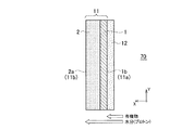
第一の導電体層1が正極であり、第二の導電体層5が負極である場合には、第一の導電体層1は第一実施形態と同様に触媒を含有することが好ましい。また、図7に示す電極複合体10Dのように、第一の導電体層1が正極であり、第二の導電体層5が負極である場合には、第一の表面11aに撥水層3を設けてもよい。   When the 1st conductor layer 1 is a positive electrode and the 2nd conductor layer 5 is a negative electrode, it is preferable that the 1st conductor layer 1 contains a catalyst similarly to 1st embodiment. Further, when the first conductor layer 1 is a positive electrode and the second conductor layer 5 is a negative electrode as in the electrode assembly 10D shown in FIG. 7, a water repellent layer is formed on the first surface 11a. 3 may be provided.

電極複合体10Cにおける第一の導電体層1、第二の導電体層5及び多孔質体層2の側面は、封止材料4によって封止されていることが好ましい。また、電極複合体10Cにおける第一の導電体層1、第二の導電体層5及び多孔質体層2の側面に加え、上面及び底面も封止材料4を用いて封止されていることが好ましい。第一の導電体層1、第二の導電体層5及び多孔質体層2の側面が封止材料4によって封止されていることにより、電極複合体10Bの内部に好気性微生物が侵入することを抑制できる。その結果、好気性微生物が電極複合体10Cの内部で増殖することを防ぐことが可能となる。   The side surfaces of the first conductor layer 1, the second conductor layer 5, and the porous body layer 2 in the electrode assembly 10 </ b> C are preferably sealed with a sealing material 4. In addition to the side surfaces of the first conductor layer 1, the second conductor layer 5, and the porous body layer 2 in the electrode assembly 10 </ b> C, the top surface and the bottom surface are sealed with the sealing material 4. Is preferred. Since the side surfaces of the first conductor layer 1, the second conductor layer 5, and the porous body layer 2 are sealed with the sealing material 4, aerobic microorganisms enter the electrode assembly 10B. This can be suppressed. As a result, it becomes possible to prevent aerobic microorganisms from growing inside the electrode assembly 10C.

本実施形態の電極複合体10C,10Dにおける多孔質体層2の作用について説明する。図7に示すように、電極複合体10Dの第一の導電体層1を微生物燃料電池の正極として用い、第二の導電体層5を負極として用いた場合、第一の導電体層1、第二の導電体層5及び多孔質体層2が電解液70に浸漬される。そして、撥水層3の面3bの少なくとも一部が気相90に露出する。この場合、気相90に露出した撥水層3を透過して第一の導電体層1に酸素が到達するため、多孔質体層2が存在しない場合には、電解液70中の好気性微生物は第一の導電体層1及び第二の導電体層5を通過する。そして、第一の導電体層1と撥水層3との界面近傍で増殖してしまう。その結果、第一の導電体層1と撥水層3との界面近傍で好気性微生物により酸素が消費されてしまうため、第一の導電体層1に担持された触媒に酸素が十分に供給されず、酸素還元反応が生じ難くなってしまう。   The operation of the porous body layer 2 in the electrode assemblies 10C and 10D of the present embodiment will be described. As shown in FIG. 7, when the first conductor layer 1 of the electrode assembly 10D is used as the positive electrode of the microbial fuel cell and the second conductor layer 5 is used as the negative electrode, the first conductor layer 1, The second conductor layer 5 and the porous body layer 2 are immersed in the electrolytic solution 70. At least a part of the surface 3 b of the water repellent layer 3 is exposed to the gas phase 90. In this case, oxygen passes through the water-repellent layer 3 exposed to the gas phase 90 and reaches the first conductor layer 1, and therefore, when the porous body layer 2 is not present, the aerobic property in the electrolytic solution 70. The microorganisms pass through the first conductor layer 1 and the second conductor layer 5. Then, it grows near the interface between the first conductor layer 1 and the water repellent layer 3. As a result, oxygen is consumed by aerobic microorganisms in the vicinity of the interface between the first conductor layer 1 and the water repellent layer 3, so that oxygen is sufficiently supplied to the catalyst supported on the first conductor layer 1. The oxygen reduction reaction is not likely to occur.

これに対し、第一の導電体層1と第二の導電体層5との間に多孔質体層2を設けた場合、電解液70中には好気性微生物の餌となる有機物が含まれるため、電解液70中に露出した第二の表面11bには微生物膜が形成される。つまり、好気性微生物が有機物を消費して繁殖し、第二の表面11bに好気性微生物が集合してなる微生物膜が形成される。好気性微生物は、酸素が供給される第一の導電体層1側へ進行しようするが、微生物膜中の好気性微生物によって有機物は消費され、多孔質体層2の内部に侵入する有機物は減少してしまう。さらに、多孔質体層2の厚さを大きくすることにより、有機物が第一の導電体層1側へ移動し難くなり、第一の導電体層1で好気性微生物が増殖できなくなる。その結果、好気性微生物による酸素消費が抑制され、第一の導電体層1に担持された触媒に酸素を十分に供給し、効果的に酸素還元反応を行うことが可能となる。   On the other hand, when the porous body layer 2 is provided between the first conductor layer 1 and the second conductor layer 5, the electrolyte 70 contains organic matter serving as a food for aerobic microorganisms. Therefore, a microbial film is formed on the second surface 11 b exposed in the electrolytic solution 70. That is, aerobic microorganisms consume organic matter and propagate, and a microbial film is formed by aerobic microorganisms gathering on the second surface 11b. Aerobic microorganisms proceed to the first conductor layer 1 side to which oxygen is supplied, but organic substances are consumed by aerobic microorganisms in the microorganism film, and organic substances that enter the porous body layer 2 are reduced. Resulting in. Furthermore, by increasing the thickness of the porous body layer 2, it becomes difficult for organic substances to move to the first conductor layer 1 side, and aerobic microorganisms cannot grow on the first conductor layer 1. As a result, oxygen consumption by aerobic microorganisms is suppressed, and oxygen can be sufficiently supplied to the catalyst supported on the first conductor layer 1 to effectively perform an oxygen reduction reaction.

[第三実施形態]
次に、第三実施形態に係る微生物燃料電池について、図面に基づき詳細に説明する。なお、第一実施形態及び第二実施形態の電極複合体と同一構成には同一符号を付し、重複する説明は省略する。
[Third embodiment]
Next, the microbial fuel cell according to the third embodiment will be described in detail with reference to the drawings. In addition, the same code | symbol is attached | subjected to the same structure as the electrode assembly of 1st embodiment and 2nd embodiment, and the overlapping description is abbreviate | omitted.

本実施形態の微生物燃料電池100は、図8及び図9に示すように、微生物を保持する負極20と、上述の電極複合体10Aにおける導電体層1からなる正極1Aとを備える。また、微生物燃料電池100は、電極複合体10Aと負極20との間に設けられ、水素イオン透過性を有するイオン移動層30をさらに備えている。   As shown in FIGS. 8 and 9, the microbial fuel cell 100 according to the present embodiment includes a negative electrode 20 that holds microorganisms, and a positive electrode 1 </ b> A that includes the conductor layer 1 in the electrode complex 10 </ b> A described above. The microbial fuel cell 100 further includes an ion moving layer 30 provided between the electrode assembly 10A and the negative electrode 20 and having hydrogen ion permeability.

(負極)
本実施形態における負極20は、後述する微生物を担持し、さらに微生物の触媒作用により、電解液70中の有機物及び窒素含有化合物の少なくとも一方から水素イオン及び電子を生成する機能を有する。そのため、本実施形態の負極20は、このような機能を生じさせる構成ならば特に限定されない。
(Negative electrode)
The negative electrode 20 in the present embodiment carries a microbe described later and further has a function of generating hydrogen ions and electrons from at least one of an organic substance and a nitrogen-containing compound in the electrolytic solution 70 by the catalytic action of the microbe. For this reason, the negative electrode 20 of the present embodiment is not particularly limited as long as it has such a function.

本実施形態の負極20は、導電性を有する導電体シートに微生物を担持した構造を有する。導電体シートとしては、多孔質の導電体シート、織布状の導電体シート及び不織布状の導電体シートからなる群より選ばれる少なくとも一つを使用することができる。また、導電体シートは複数のシートを積層した積層体でもよい。負極20の導電体シートとして、このような複数の細孔を有するシートを用いることにより、後述する局部電池反応で生成した水素イオンがイオン移動層30の方向へ移動しやすくなり、酸素還元反応の速度を高めることが可能となる。また、イオン透過性を向上させる観点から、負極20の導電体シートは、電極複合体10A、イオン移動層30及び負極20の積層方向X、つまり厚さ方向に連続した空間(空隙)を有していることが好ましい。   The negative electrode 20 of the present embodiment has a structure in which microorganisms are supported on a conductive sheet having conductivity. As the conductor sheet, it is possible to use at least one selected from the group consisting of a porous conductor sheet, a woven conductor sheet, and a nonwoven conductor sheet. The conductor sheet may be a laminate in which a plurality of sheets are laminated. By using such a sheet having a plurality of pores as the conductor sheet of the negative electrode 20, hydrogen ions generated in the local battery reaction described later easily move toward the ion moving layer 30, and the oxygen reduction reaction The speed can be increased. Further, from the viewpoint of improving ion permeability, the conductor sheet of the negative electrode 20 has a space (void) continuous in the stacking direction X of the electrode composite 10A, the ion moving layer 30 and the negative electrode 20, that is, in the thickness direction. It is preferable.

当該導電体シートは、厚さ方向に複数の貫通孔を有する金属板であってもよい。そのため、負極20の導電体シートを構成する材料としては、例えば、アルミニウム、銅、ステンレス鋼、ニッケル及びチタンなどの導電性金属、並びにカーボンペーパー、カーボンフェルトからなる群より選ばれる少なくとも一つを用いることができる。   The conductor sheet may be a metal plate having a plurality of through holes in the thickness direction. Therefore, as a material constituting the conductor sheet of the negative electrode 20, for example, at least one selected from the group consisting of conductive metals such as aluminum, copper, stainless steel, nickel and titanium, carbon paper, and carbon felt is used. be able to.

負極20の導電体シートとして、黒鉛シートを用いてもよい。また、負極20は黒鉛を含有し、さらに黒鉛におけるグラフェン層は、電極複合体10A、イオン移動層30及び負極20の積層方向Xに垂直な方向YZの面に沿って配列していることが好ましい。グラフェン層がこのように配列していることにより、積層方向Xの導電性よりも、積層方向Xに垂直な方向YZの導電性が向上する。そのため、負極20の局部電池反応により生成した電子を外部回路110へ導通させやすくなり、電池反応の効率をより向上させることが可能となる。   A graphite sheet may be used as the conductor sheet of the negative electrode 20. Moreover, the negative electrode 20 preferably contains graphite, and the graphene layer in the graphite is preferably arranged along a plane in a direction YZ perpendicular to the stacking direction X of the electrode composite 10A, the ion transfer layer 30, and the negative electrode 20. . By arranging the graphene layers in this way, the conductivity in the direction YZ perpendicular to the stacking direction X is improved as compared with the conductivity in the stacking direction X. Therefore, it becomes easy to conduct the electrons generated by the local battery reaction of the negative electrode 20 to the external circuit 110, and the efficiency of the battery reaction can be further improved.

なお、上述の黒鉛シートは、次のようにして得ることができる。まず、天然黒鉛を酸によって化学処理を施し、黒鉛のグラフェン層の層間へ挿入物を形成する。次に、これを高温で急速加熱することで、層間挿入物の熱分解によるガス圧でグラフェン層間が押し広がった膨張黒鉛が得られる。そして、この膨張黒鉛を加圧し、ロール圧延することにより、黒鉛シートが得られる。このようにして得られた黒鉛シートを負極20の導電体シートとして用いた場合、黒鉛におけるグラフェン層が積層方向Xに垂直な方向YZに沿って配列している。そのため、負極20と外部回路110との間の導電性を高め、電池反応の効率をより向上させることが可能となる。   The above graphite sheet can be obtained as follows. First, natural graphite is chemically treated with an acid to form an insert between the graphite graphene layers. Next, this is rapidly heated at a high temperature to obtain expanded graphite in which the graphene interlayer is pushed and expanded by the gas pressure due to the thermal decomposition of the intercalated insert. Then, the expanded graphite is pressurized and roll-rolled to obtain a graphite sheet. When the graphite sheet obtained in this way is used as the conductor sheet of the negative electrode 20, the graphene layers in the graphite are arranged along the direction YZ perpendicular to the stacking direction X. Therefore, the conductivity between the negative electrode 20 and the external circuit 110 can be increased, and the efficiency of the battery reaction can be further improved.

負極20に担持される微生物としては、電解液70中の有機物、又は窒素を含む化合物を分解する微生物であれば特に限定されないが、例えば増殖に酸素を必要としない嫌気性微生物を使用することが好ましい。嫌気性微生物は、電解液70中の有機物を酸化分解するための空気を必要としない。そのため、空気を送り込むために必要な電力を大幅に低減することができる。また、微生物が獲得する自由エネルギーが小さいので、汚泥発生量を減少させることが可能となる。   The microorganism supported on the negative electrode 20 is not particularly limited as long as it is a microorganism that decomposes an organic substance in the electrolyte solution 70 or a compound containing nitrogen. For example, an anaerobic microorganism that does not require oxygen for growth is used. preferable. Anaerobic microorganisms do not require air for oxidizing and decomposing organic substances in the electrolyte solution 70. Therefore, the electric power required for sending air can be significantly reduced. Moreover, since the free energy which microbes acquire is small, it becomes possible to reduce the amount of sludge generation.

負極20に保持される嫌気性微生物は、例えば細胞外電子伝達機構を有する電気生産細菌であることが好ましい。具体的には、嫌気性微生物として、例えばGeobacter属細菌、Shewanella属細菌、Aeromonas属細菌、Geothrix属細菌、Saccharomyces属細菌が挙げられる。   The anaerobic microorganism held in the negative electrode 20 is preferably an electricity producing bacterium having an extracellular electron transfer mechanism, for example. Specifically, examples of the anaerobic microorganism include Geobacter genus bacteria, Shewanella genus bacteria, Aeromonas genus bacteria, Geothrix genus bacteria, and Saccharomyces genus bacteria.

負極20に、嫌気性微生物を含むバイオフィルムが重ねられて固定されることで、負極20に嫌気性微生物が保持されていてもよい。なお、バイオフィルムとは、一般に、微生物集団と、微生物集団が生産する菌体外重合体物質(extracellular polymeric substance、EPS)とを含む三次元構造体のことをいう。ただ、嫌気性微生物は、バイオフィルムによらずに負極20に保持されていてもよい。また、嫌気性微生物は、負極20表面だけでなく、内部に保持されていてもよい。   Anaerobic microorganisms may be held on the negative electrode 20 by stacking and fixing a biofilm containing anaerobic microorganisms on the negative electrode 20. The biofilm generally refers to a three-dimensional structure including a microbial population and an extracellular polymeric substance (EPS) produced by the microbial population. However, the anaerobic microorganisms may be held on the negative electrode 20 without depending on the biofilm. Moreover, the anaerobic microorganisms may be held not only on the surface of the negative electrode 20 but also inside.

(正極)
本実施形態の微生物燃料電池100は、図2に示す電極複合体10Aにおける導電体層1からなる正極1Aを備えている。
(Positive electrode)
The microbial fuel cell 100 of the present embodiment includes a positive electrode 1A composed of the conductor layer 1 in the electrode complex 10A shown in FIG.

(イオン移動層)
本実施形態の微生物燃料電池100は、電極複合体10Aの多孔質体層2と負極20との間に設けられ、プロトン透過性を有するイオン移動層30をさらに備える。つまり、電極複合体10Aにおける多孔質体層2の面2a側にイオン移動層30が設けられている。そして、図8及び図9に示すように、負極20は、イオン移動層30を介して電極複合体10Aと隔てられている。イオン移動層30は、負極20で生成した水素イオンを透過し、電極複合体10A側へ移動させる機能を有している。
(Ion moving layer)
The microbial fuel cell 100 of the present embodiment further includes an ion transfer layer 30 provided between the porous body layer 2 of the electrode assembly 10A and the negative electrode 20 and having proton permeability. That is, the ion migration layer 30 is provided on the surface 2a side of the porous body layer 2 in the electrode assembly 10A. As shown in FIGS. 8 and 9, the negative electrode 20 is separated from the electrode assembly 10 </ b> A through the ion moving layer 30. The ion moving layer 30 has a function of transmitting hydrogen ions generated in the negative electrode 20 and moving the hydrogen ions to the electrode assembly 10A side.

イオン移動層30としては、例えばイオン交換樹脂を用いたイオン交換膜を使用することができる。イオン交換樹脂としては、例えばデュポン株式会社製のNAFION(登録商標)、並びに旭硝子株式会社製のフレミオン(登録商標)及びセレミオン(登録商標)を用いることができる。   As the ion migration layer 30, for example, an ion exchange membrane using an ion exchange resin can be used. As the ion exchange resin, for example, NAFION (registered trademark) manufactured by DuPont, and Flemion (registered trademark) and Selemion (registered trademark) manufactured by Asahi Glass Co., Ltd. can be used.

また、イオン移動層30として、水素イオンが透過することが可能な細孔を有する多孔質膜を使用してもよい。つまり、イオン移動層30は、負極20から電極複合体10Aへ水素イオンが移動するための空間(空隙)を有するシートであってもよい。そのため、イオン移動層30は、多孔質のシート、織布状のシート及び不織布状のシートからなる群より選ばれる少なくとも一つを備えることが好ましい。また、イオン移動層30は、ガラス繊維膜、合成繊維膜、及びプラスチック不織布からなる群より選ばれる少なくとも一つを用いることができ、これらを複数積層してなる積層体でもよい。このような多孔質のシートは、内部に多数の細孔を有しているため、水素イオンが容易に移動することが可能となる。なお、イオン移動層30の細孔径は、負極20から電極複合体10Aに水素イオンが移動できれば特に限定されない。   Further, a porous membrane having pores through which hydrogen ions can permeate may be used as the ion moving layer 30. That is, the ion moving layer 30 may be a sheet having a space (void) for moving hydrogen ions from the negative electrode 20 to the electrode assembly 10A. Therefore, the ion migration layer 30 preferably includes at least one selected from the group consisting of a porous sheet, a woven sheet, and a nonwoven sheet. Moreover, the ion migration layer 30 can use at least one chosen from the group which consists of a glass fiber membrane, a synthetic fiber membrane, and a plastic nonwoven fabric, and the laminated body formed by laminating | stacking these two or more may be used. Since such a porous sheet has a large number of pores inside, hydrogen ions can easily move. The pore diameter of the ion moving layer 30 is not particularly limited as long as hydrogen ions can move from the negative electrode 20 to the electrode composite 10A.

上述のように、イオン移動層30は、負極20で生成した水素イオンを透過し、電極複合体10A側へ移動させる機能を有する。そのため、例えば、負極20と電極複合体10Aとが接触しない状態で近接していれば、水素イオンが負極20から正極1Aへ移動することができる。そのため、本実施形態の微生物燃料電池100において、イオン移動層30は必須の構成要素ではない。ただ、イオン移動層30を設けることにより、負極20から正極1Aへ水素イオンを効率的に移動させることが可能となるため、出力向上の観点からイオン移動層30を設けることが好ましい。   As described above, the ion moving layer 30 has a function of transmitting the hydrogen ions generated in the negative electrode 20 and moving the hydrogen ions to the electrode assembly 10A side. Therefore, for example, if the negative electrode 20 and the electrode assembly 10A are close to each other without being in contact with each other, hydrogen ions can move from the negative electrode 20 to the positive electrode 1A. Therefore, in the microbial fuel cell 100 of this embodiment, the ion moving layer 30 is not an essential component. However, since the provision of the ion moving layer 30 enables efficient movement of hydrogen ions from the negative electrode 20 to the positive electrode 1A, it is preferable to provide the ion moving layer 30 from the viewpoint of improving the output.

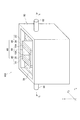
図8及び図9に示すように、本実施形態に係る微生物燃料電池100は、電極複合体10A、負極20及びイオン移動層30からなる複数の電極接合体40を備えている。微生物燃料電池100では、図9に示すように、イオン移動層30の一方の面30aに負極20が接触するように配置されており、イオン移動層30の面30aと反対側の面30bに電極複合体10Aが接触するように配置されている。   As shown in FIGS. 8 and 9, the microbial fuel cell 100 according to the present embodiment includes a plurality of electrode assemblies 40 including an electrode assembly 10 </ b> A, a negative electrode 20, and an ion transfer layer 30. In the microbial fuel cell 100, as shown in FIG. 9, the negative electrode 20 is disposed so as to contact one surface 30 a of the ion moving layer 30, and an electrode is disposed on the surface 30 b opposite to the surface 30 a of the ion moving layer 30. It arrange | positions so that 10 A of composites may contact.

図10に示すように、2枚の電極接合体40は、電極複合体10Aの撥水層3同士が対向するように、カセット基材50を介して積層されている。カセット基材50は、電極複合体10Aの撥水層3における面3bの外周部に沿うU字状の枠部材であり、上部が開口している。つまり、カセット基材50は、2本の第一柱状部材51の底面を第二柱状部材52で連結した枠部材である。そして、カセット基材50の側面53は、撥水層3における面3bの外周部と接合されており、撥水層3における面3bの外周部からカセット基材50の内部に電解液70が漏出することを抑制できる。   As shown in FIG. 10, the two electrode assemblies 40 are laminated via the cassette base material 50 so that the water-repellent layers 3 of the electrode assembly 10A face each other. The cassette base material 50 is a U-shaped frame member along the outer peripheral portion of the surface 3b of the water repellent layer 3 of the electrode assembly 10A, and the upper portion is open. That is, the cassette base material 50 is a frame member in which the bottom surfaces of the two first columnar members 51 are connected by the second columnar member 52. The side surface 53 of the cassette base material 50 is joined to the outer peripheral portion of the surface 3 b of the water repellent layer 3, and the electrolyte solution 70 leaks into the cassette base material 50 from the outer peripheral portion of the surface 3 b of the water repellent layer 3. Can be suppressed.

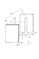
そして、図9に示すように、2枚の電極接合体40とカセット基材50とを積層してなる燃料電池ユニット60は、大気と連通した気相90が形成されるように、廃水槽80の内部に配置される。廃水槽80の内部には被処理液である電解液70が保持されており、電極複合体10Aの正極1A及び多孔質体層2、負極20並びにイオン移動層30は電解液70に浸漬されている。   As shown in FIG. 9, the fuel cell unit 60 formed by laminating the two electrode assemblies 40 and the cassette base material 50 has a wastewater tank 80 so that a gas phase 90 communicating with the atmosphere is formed. Placed inside. The wastewater tank 80 holds an electrolytic solution 70 as a liquid to be treated, and the positive electrode 1A, the porous body layer 2, the negative electrode 20, and the ion transfer layer 30 of the electrode composite 10A are immersed in the electrolytic solution 70. Yes.

上述のように、電極複合体10Aの撥水層3は撥水性を有する。そのため、廃水槽80の内部に保持された電解液70とカセット基材50の内部とは隔てられ、2枚の電極接合体40とカセット基材50とにより形成された内部空間は気相90となっている。そして、図9に示すように、正極1A及び負極20は、それぞれ外部回路110と電気的に接続されている。   As described above, the water repellent layer 3 of the electrode composite 10A has water repellency. Therefore, the electrolytic solution 70 held in the waste water tank 80 is separated from the inside of the cassette base material 50, and the internal space formed by the two electrode assemblies 40 and the cassette base material 50 is the gas phase 90. It has become. As shown in FIG. 9, the positive electrode 1A and the negative electrode 20 are electrically connected to the external circuit 110, respectively.

次に、本実施形態の微生物燃料電池100の作用について説明する。上述の電極複合体10A、負極20及びイオン移動層30からなる電極接合体40が電解液70に浸漬された場合、電極複合体10Aの正極1A、多孔質体層2及び負極20が電解液70に浸漬され、撥水層3の少なくとも一部が気相90に露出している。   Next, the operation of the microbial fuel cell 100 of this embodiment will be described. When the electrode assembly 40 composed of the electrode assembly 10A, the negative electrode 20, and the ion moving layer 30 is immersed in the electrolytic solution 70, the positive electrode 1A, the porous body layer 2, and the negative electrode 20 of the electrode composite 10A are the electrolytic solution 70. So that at least a part of the water-repellent layer 3 is exposed to the gas phase 90.

微生物燃料電池100の動作時には、負極20に、有機物及び窒素含有化合物の少なくとも一方を含有する電解液70を供給し、電極複合体10Aに空気を供給する。この際、空気は、カセット基材50の上部に設けられた開口部を通じて連続的に供給される。   During the operation of the microbial fuel cell 100, an electrolyte solution 70 containing at least one of an organic substance and a nitrogen-containing compound is supplied to the negative electrode 20, and air is supplied to the electrode assembly 10A. At this time, the air is continuously supplied through an opening provided in the upper part of the cassette base material 50.

そして、電極複合体10Aでは、撥水層3を透過して正極1Aに酸素が拡散する。負極20では、嫌気性微生物の触媒作用により、電解液70中の有機物及び窒素含有化合物の少なくとも一方から水素イオン及び電子を生成する。生成した水素イオンは、イオン移動層30を透過して電極複合体10A側へ移動する。さらに水素イオンは、電極複合体10A中の多孔質体層2を透過して、正極1Aに到達する。また、生成した電子は負極20の導電体シートを通じて外部回路110へ移動し、さらに外部回路110から正極1Aに移動する。そして、水素イオン及び電子は、正極1A中の触媒の作用により酸素と結合し、水となって消費される。このとき、外部回路110によって、閉回路に流れる電気エネルギーを回収する。   In the electrode assembly 10A, oxygen diffuses through the water-repellent layer 3 to the positive electrode 1A. In the negative electrode 20, hydrogen ions and electrons are generated from at least one of the organic substance and the nitrogen-containing compound in the electrolytic solution 70 by the catalytic action of anaerobic microorganisms. The generated hydrogen ions pass through the ion moving layer 30 and move to the electrode assembly 10A side. Further, the hydrogen ions pass through the porous body layer 2 in the electrode assembly 10A and reach the positive electrode 1A. Further, the generated electrons move to the external circuit 110 through the conductor sheet of the negative electrode 20, and further move from the external circuit 110 to the positive electrode 1A. And hydrogen ion and an electron couple | bond with oxygen by the effect | action of the catalyst in 1 A of positive electrodes, and are consumed as water. At this time, the electric energy flowing in the closed circuit is recovered by the external circuit 110.

ここで、電解液70には、上述の嫌気性微生物に加え、増殖に酸素を必要とする好気性微生物も含まれている。電極複合体10Aは、正極1Aに多孔質体層2を設けていることから、図4に示すように、多孔質体層2の面2aには微生物膜12が形成される。好気性微生物は、酸素が供給される気相90側へ進行しようするが、微生物膜12中の好気性微生物によって有機物は消費され、多孔質体層2の内部に侵入する有機物は減少してしまう。さらに、多孔質体層2が所定の厚さを有しているため、有機物が正極1A側へ移動し難くなり、正極1Aと多孔質体層2の境界よりも正極1A側では好気性微生物が増殖できなくなる。その結果、正極1Aと撥水層3との界面近傍で好気性微生物が増殖されないことから、好気性微生物による酸素消費が抑制され、酸素還元反応を効率的に行うことが可能となる。   Here, in addition to the anaerobic microorganisms described above, the electrolytic solution 70 also includes aerobic microorganisms that require oxygen for growth. Since the electrode assembly 10A is provided with the porous body layer 2 on the positive electrode 1A, the microbial membrane 12 is formed on the surface 2a of the porous body layer 2 as shown in FIG. The aerobic microorganisms proceed to the gas phase 90 side to which oxygen is supplied. However, the organic substances are consumed by the aerobic microorganisms in the microorganism film 12, and the organic substances entering the porous body layer 2 are reduced. . Furthermore, since the porous body layer 2 has a predetermined thickness, it becomes difficult for organic substances to move to the positive electrode 1A side, and aerobic microorganisms are present on the positive electrode 1A side from the boundary between the positive electrode 1A and the porous body layer 2. Can no longer grow. As a result, since the aerobic microorganisms are not grown near the interface between the positive electrode 1A and the water repellent layer 3, oxygen consumption by the aerobic microorganisms is suppressed, and the oxygen reduction reaction can be performed efficiently.

このように、本実施形態の微生物燃料電池100は、電極複合体10を用いた第一の電極(正極1A)と、第二の電極(負極20)とを有する。この場合、電極複合体10における第一の導電体層(導電体層1)が第一の電極(正極1A)となる。さらに微生物燃料電池100は、電極複合体10における第二の表面11bと、第二の電極との間に設けられ、プロトン透過性を有するイオン移動層30を備える。このような構成により、正極1Aにおいて好気性微生物による酸素消費阻害が生じ難くなることから、正極1Aにおける酸素還元特性を高め、安定的に電気エネルギーを生産することが可能となる。   Thus, the microbial fuel cell 100 of the present embodiment includes the first electrode (positive electrode 1A) using the electrode assembly 10 and the second electrode (negative electrode 20). In this case, the first conductor layer (conductor layer 1) in the electrode assembly 10 becomes the first electrode (positive electrode 1A). The microbial fuel cell 100 further includes an ion transfer layer 30 provided between the second surface 11b of the electrode assembly 10 and the second electrode and having proton permeability. Such a configuration makes it difficult for the positive electrode 1A to inhibit oxygen consumption due to aerobic microorganisms, so that the oxygen reduction characteristics of the positive electrode 1A can be improved and electric energy can be stably produced.

電極複合体10において、多孔質体層2が電気絶縁性である場合、図11に示すように、微生物燃料電池100Aはイオン移動層30を設けなくてもよい。具体的には、微生物燃料電池100Aは、電極複合体10及び負極20からなる複数の電極接合体40Aを備えている。微生物燃料電池100Aでは、負極20の一方の面20aが、電極複合体10における多孔質体層2の面2aと接触するように配置されている。そして、2枚の電極接合体40Aは、電極複合体10Aの撥水層3同士が対向するように、カセット基材50を介して積層されている。カセット基材50の側面53は、撥水層3における面3bの外周部と接合されている。また、2枚の電極接合体40Aとカセット基材50とを積層してなる燃料電池ユニット60Aは、気相90が形成されるように、廃水槽80の内部に配置され、電極複合体10Aの正極1A及び多孔質体層2、並びに負極20は電解液70に浸漬されている。   In the electrode assembly 10, when the porous body layer 2 is electrically insulating, the microbial fuel cell 100 </ b> A does not need to provide the ion transfer layer 30 as shown in FIG. 11. Specifically, the microbial fuel cell 100 </ b> A includes a plurality of electrode assemblies 40 </ b> A composed of the electrode assembly 10 and the negative electrode 20. In the microbial fuel cell 100 </ b> A, one surface 20 a of the negative electrode 20 is disposed so as to be in contact with the surface 2 a of the porous body layer 2 in the electrode assembly 10. And two electrode assembly 40A is laminated | stacked through the cassette base material 50 so that the water-repellent layers 3 of electrode assembly 10A may face each other. The side surface 53 of the cassette base material 50 is joined to the outer peripheral portion of the surface 3 b in the water repellent layer 3. Further, the fuel cell unit 60A formed by laminating the two electrode assemblies 40A and the cassette base material 50 is arranged inside the waste water tank 80 so that the gas phase 90 is formed, and the electrode assembly 10A The positive electrode 1A, the porous body layer 2, and the negative electrode 20 are immersed in the electrolytic solution 70.

電極複合体10Aの多孔質体層2が電気絶縁性である場合、電極複合体10Aの正極1Aと負極20とは多孔質体層2により絶縁されているため、イオン移動層30を介在させなくても、導電体層1と負極20との間の短絡を防ぐことができる。また、上述のように、多孔質体層2は水素イオンを透過し、導電体層1に水素イオンを到達させることができる。このように、多孔質体層2がイオン移動層30と同じ機能を果たすことができるため、イオン移動層30を設けなくてもよい。なお、図11では、負極20の一方の面20aが電極複合体10Aにおける多孔質体層2の面2aと接触するように配置されているが、負極20の面20aと多孔質体層2の面2aとの間には空隙が存在していてもよい。   When the porous body layer 2 of the electrode composite body 10A is electrically insulating, the positive electrode 1A and the negative electrode 20 of the electrode composite body 10A are insulated by the porous body layer 2, so that the ion migration layer 30 is not interposed. However, a short circuit between the conductor layer 1 and the negative electrode 20 can be prevented. In addition, as described above, the porous body layer 2 can transmit hydrogen ions and can reach the conductor layer 1. Thus, since the porous body layer 2 can perform the same function as the ion moving layer 30, the ion moving layer 30 may not be provided. In FIG. 11, the one surface 20 a of the negative electrode 20 is disposed so as to be in contact with the surface 2 a of the porous body layer 2 in the electrode assembly 10 </ b> A, but the surface 20 a of the negative electrode 20 and the porous body layer 2 are arranged. There may be a gap between the surface 2a.

本実施形態に係る負極20には、例えば、電子伝達メディエーター分子が修飾されていてもよい。あるいは、廃水槽80内の電解液70は、電子伝達メディエーター分子を含んでいてもよい。これにより、嫌気性微生物から負極20への電子移動を促進し、より効率的な液体処理を実現できる。   For example, the negative electrode 20 according to the present embodiment may be modified with an electron transfer mediator molecule. Alternatively, the electrolytic solution 70 in the waste water tank 80 may contain electron transfer mediator molecules. Thereby, the electron transfer from an anaerobic microorganism to the negative electrode 20 is accelerated | stimulated, and more efficient liquid processing is realizable.

具体的には、嫌気性微生物による代謝機構では、細胞内又は最終電子受容体との間で電子の授受が行われる。電解液70中にメディエーター分子を導入すると、メディエーター分子が代謝の最終電子受容体として作用し、かつ、受け取った電子を負極20へと受け渡す。この結果、電解液70における有機物などの酸化分解速度を高めることが可能になる。このような電子伝達メディエーター分子は、特に限定されない。電子伝達メディエーター分子としては、例えばニュートラルレッド、アントラキノン−2,6−ジスルホン酸(AQDS)、チオニン、フェリシアン化カリウム、及びメチルビオローゲンからなる群より選ばれる少なくとも一つを用いることができる。   Specifically, in the metabolic mechanism by anaerobic microorganisms, electrons are transferred between cells or with the final electron acceptor. When a mediator molecule is introduced into the electrolytic solution 70, the mediator molecule acts as a final electron acceptor of metabolism, and delivers received electrons to the negative electrode 20. As a result, it becomes possible to increase the rate of oxidative decomposition of the organic matter in the electrolytic solution 70. Such an electron transfer mediator molecule is not particularly limited. As the electron transfer mediator molecule, for example, at least one selected from the group consisting of neutral red, anthraquinone-2,6-disulfonic acid (AQDS), thionine, potassium ferricyanide, and methylviologen can be used.

図10に示す燃料電池ユニット60は、2枚の電極接合体40とカセット基材50とを積層する構成となっている。しかし、本実施形態はこの構成に限定されない。例えば、カセット基材50の一方の側面53のみに電極接合体40を接合し、他方の側面は板部材で封止してもよい。また、図8乃至図10に示すカセット基材50は、上部の全体が開口しているが、内部に空気(酸素)を導入することが可能ならば部分的に開口していてもよく、また閉口していてもよい。   The fuel cell unit 60 shown in FIG. 10 has a configuration in which two electrode assemblies 40 and a cassette base material 50 are stacked. However, the present embodiment is not limited to this configuration. For example, the electrode assembly 40 may be bonded to only one side surface 53 of the cassette base material 50 and the other side surface may be sealed with a plate member. 8 to 10, the entire upper portion of the cassette base 50 is open, but may be partially open if air (oxygen) can be introduced into the inside. It may be closed.

廃水槽80は内部に電解液70を保持しているが、電解液70が流通するような構成であってもよい。例えば、図8及び図9に示すように、廃水槽80には、電解液70を廃水槽80に供給するための廃水供給口81と、処理後の電解液70を廃水槽80から排出するための廃水排出口82とが設けられていてもよい。そして、電解液70は、廃水供給口81及び廃水排出口82を通じて連続的に供給されることが好ましい。   The waste water tank 80 holds the electrolytic solution 70 therein, but may have a configuration in which the electrolytic solution 70 circulates. For example, as shown in FIGS. 8 and 9, in the wastewater tank 80, a wastewater supply port 81 for supplying the electrolytic solution 70 to the wastewater tank 80 and a discharged electrolytic solution 70 after the treatment are discharged from the wastewater tank 80. The waste water discharge port 82 may be provided. The electrolytic solution 70 is preferably continuously supplied through the waste water supply port 81 and the waste water discharge port 82.

廃水槽80内は、例えば分子状酸素が存在しない、又は分子状酸素が存在してもその濃度が極めて小さい嫌気性条件に保たれていることが好ましい。これにより、廃水槽80内で、電解液70を酸素と殆ど接触しないように保持することが可能となる。   It is preferable that the inside of the waste water tank 80 is maintained in anaerobic conditions in which, for example, molecular oxygen does not exist or even if molecular oxygen is present, the concentration thereof is extremely small. Thereby, it becomes possible to hold | maintain the electrolyte solution 70 so that it may hardly contact oxygen in the wastewater tank 80. FIG.

[第四実施形態]
次に、第四実施形態に係る微生物燃料電池について、図面に基づき詳細に説明する。なお、第一実施形態及び第二実施形態の電極複合体、並びに第三実施形態に係る微生物燃料電池と同一構成には同一符号を付し、重複する説明は省略する。
[Fourth embodiment]
Next, a microbial fuel cell according to a fourth embodiment will be described in detail with reference to the drawings. In addition, the same code | symbol is attached | subjected to the structure same as the microbial fuel cell which concerns on the electrode assembly of 1st embodiment and 2nd embodiment, and 3rd embodiment, and the overlapping description is abbreviate | omitted.

本実施形態の微生物燃料電池100Bは、図12に示すように、正極1Bと、上述の電極複合体10における導電体層1からなる負極20Aとを備える。   As shown in FIG. 12, the microbial fuel cell 100 </ b> B of the present embodiment includes a positive electrode 1 </ b> B and a negative electrode 20 </ b> A composed of the conductor layer 1 in the electrode assembly 10 described above.

(正極)
本実施形態に係る正極1Bは、負極20Aで生成した水素イオン及び電子と、気相90中の酸素との酸素還元反応を進行させる機能を有する。そのため、本実施形態の正極1Bは、このような機能を生じさせる構成ならば特に限定されない。正極1Bとしては、例えば撥水層と、撥水層に接触するように重ねられているガス拡散層とを備えるガス拡散電極を使用することができる。このような薄板状のガス拡散電極を用いることにより、気相90中の酸素を正極1B中の触媒に容易に供給することが可能になる。
(Positive electrode)
The positive electrode 1B according to the present embodiment has a function of causing an oxygen reduction reaction between hydrogen ions and electrons generated in the negative electrode 20A and oxygen in the gas phase 90. For this reason, the positive electrode 1B of the present embodiment is not particularly limited as long as it has such a function. As the positive electrode 1B, for example, a gas diffusion electrode including a water repellent layer and a gas diffusion layer stacked so as to be in contact with the water repellent layer can be used. By using such a thin plate-like gas diffusion electrode, oxygen in the gas phase 90 can be easily supplied to the catalyst in the positive electrode 1B.

正極1Bにおける撥水層は、撥水性と酸素透過性とを併せ持つ層である。撥水層は、微生物燃料電池100Bにおける電気化学系中の気相と液相とを良好に分離しながら、気相から液相へ向かう酸素の移動を許容するように構成される。つまり、撥水層は、気相90中の酸素を透過し、ガス拡散層へ移動させつつも、電解液70が気相90側に移動することを抑制できる。このような撥水層としては、第一実施形態の撥水層3と同じものを使用することができる。   The water repellent layer in the positive electrode 1B is a layer having both water repellency and oxygen permeability. The water repellent layer is configured to allow oxygen to move from the gas phase to the liquid phase while favorably separating the gas phase and the liquid phase in the electrochemical system of the microbial fuel cell 100B. That is, the water-repellent layer can suppress the movement of the electrolytic solution 70 toward the gas phase 90 while allowing oxygen in the gas phase 90 to permeate and move to the gas diffusion layer. As such a water-repellent layer, the same layer as the water-repellent layer 3 of the first embodiment can be used.

正極1Bにおけるガス拡散層は、多孔質な導電性材料と、この導電性材料に担持されている触媒とを備えることが好ましい。なお、ガス拡散層が、多孔質かつ導電性を有する触媒から構成されてもよい。正極1Bにこのようなガス拡散層を備えることで、負極で生成した電子を触媒と外部回路110との間で導通させることが可能となる。なお、当該触媒は、第一実施形態で説明したものと同じ触媒を使用することができる。   The gas diffusion layer in the positive electrode 1B preferably includes a porous conductive material and a catalyst supported on the conductive material. The gas diffusion layer may be composed of a porous and conductive catalyst. By providing such a gas diffusion layer in the positive electrode 1 </ b> B, it is possible to conduct electrons generated in the negative electrode between the catalyst and the external circuit 110. In addition, the said catalyst can use the same catalyst as what was demonstrated in 1st embodiment.

正極1Bでは、安定的な性能を確保するために、酸素が撥水層及びガス拡散層を効率よく透過し、触媒に供給されることが好ましい。そのため、ガス拡散層は、撥水層と対向する面から反対側の面にかけて、酸素が透過する細孔を多数有する多孔質体であることが好ましい。また、ガス拡散層の形状は、三次元のメッシュ状であることが特に好ましい。このようなメッシュ状であることにより、ガス拡散層に対し、高い酸素透過性及び導電性を付与することが可能となる。   In the positive electrode 1B, in order to ensure stable performance, it is preferable that oxygen is efficiently transmitted through the water-repellent layer and the gas diffusion layer and supplied to the catalyst. Therefore, the gas diffusion layer is preferably a porous body having a large number of pores through which oxygen passes from the surface facing the water repellent layer to the surface on the opposite side. The shape of the gas diffusion layer is particularly preferably a three-dimensional mesh. With such a mesh shape, it is possible to impart high oxygen permeability and conductivity to the gas diffusion layer.

正極1Bにおいて、ガス拡散層に効率的に酸素を供給するために、撥水層は、接着剤を介してガス拡散層と接合していることが好ましい。これにより、ガス拡散層に対し、拡散した酸素が直接供給され、酸素還元反応を効率的に行うことができる。接着剤は、第一実施形態で説明したものと同じ接着剤を使用することができる。   In the positive electrode 1B, in order to efficiently supply oxygen to the gas diffusion layer, the water repellent layer is preferably bonded to the gas diffusion layer through an adhesive. Thereby, the diffused oxygen is directly supplied to the gas diffusion layer, and the oxygen reduction reaction can be performed efficiently. As the adhesive, the same adhesive as described in the first embodiment can be used.

ここで、本実施形態における正極1Bのガス拡散層について、さらに詳しく説明する。上述のように、ガス拡散層は、多孔質な導電性材料と、当該導電性材料に担持されている触媒とを備えるような構成とすることができる。   Here, the gas diffusion layer of the positive electrode 1B in the present embodiment will be described in more detail. As described above, the gas diffusion layer can be configured to include a porous conductive material and a catalyst supported on the conductive material.

ガス拡散層における導電性材料は、例えば炭素系物質、導電性ポリマー、半導体及び金属からなる群より選ばれる一種以上の材料から構成することができる。ここで、炭素系物質とは、炭素を構成成分とする物質をいう。炭素系物質の例としては、例えば、グラファイト、活性炭、カーボンブラック、バルカン(登録商標)XC−72R、アセチレンブラック、ファーネスブラック、デンカブラックなどのカーボンパウダー、グラファイトフェルト、カーボンウール、カーボン織布などのカーボンファイバー、カーボンプレート、カーボンペーパー、カーボンディスク、カーボンクロス、カーボンホイル、炭素粒子を圧縮成形した炭素系材料が挙げられる。また、炭素系物質の例として、カーボンナノチューブ、カーボンナノホーン、カーボンナノクラスターのような微細構造物質も挙げられる。さらに、ガス拡散層における導電性材料としては、メッシュ及び発泡体等の金属材料も用いることができる。   The conductive material in the gas diffusion layer can be composed of, for example, one or more materials selected from the group consisting of carbon-based substances, conductive polymers, semiconductors, and metals. Here, the carbon-based material means a material containing carbon as a constituent component. Examples of carbon-based materials include, for example, carbon powder such as graphite, activated carbon, carbon black, Vulcan (registered trademark) XC-72R, acetylene black, furnace black, Denka black, graphite felt, carbon wool, carbon woven cloth, etc. Carbon fiber, carbon plate, carbon paper, carbon disk, carbon cloth, carbon foil, and carbon-based material obtained by compression molding carbon particles are included. Examples of the carbon-based material also include fine-structured materials such as carbon nanotubes, carbon nanohorns, and carbon nanoclusters. Furthermore, as a conductive material in the gas diffusion layer, a metal material such as a mesh and a foam can also be used.

導電性ポリマーとは、導電性を有する高分子化合物の総称である。導電性ポリマーとしては、例えば、アニリン、アミノフェノール、ジアミノフェノール、ピロール、チオフェン、パラフェニレン、フルオレン、フラン、アセチレン若しくはそれらの誘導体を構成単位とする単一モノマー又は2種以上のモノマーの重合体が挙げられる。具体的には、導電性ポリマーとして、例えば、ポリアニリン、ポリアミノフェノール、ポリジアミノフェノール、ポリピロール、ポリチオフェン、ポリパラフェニレン、ポリフルオレン、ポリフラン、ポリアセチレン等が挙げられる。金属製の導電性材料としては、例えば、ステンレスメッシュが挙げられる。入手の容易性、コスト、耐食性、耐久性等を考慮した場合、導電性材料は炭素系物質であることが好ましい。   The conductive polymer is a general term for polymer compounds having conductivity. Examples of the conductive polymer include aniline, aminophenol, diaminophenol, pyrrole, thiophene, paraphenylene, fluorene, furan, acetylene, or a polymer of two or more monomers having a structural unit as a constituent unit. Can be mentioned. Specifically, examples of the conductive polymer include polyaniline, polyaminophenol, polydiaminophenol, polypyrrole, polythiophene, polyparaphenylene, polyfluorene, polyfuran, and polyacetylene. An example of the metal conductive material is a stainless mesh. In consideration of availability, cost, corrosion resistance, durability, and the like, the conductive material is preferably a carbon-based substance.

また、導電性材料の形状は、粉末形状又は繊維形状であることが好ましい。また、導電性材料は、支持体に支持されていてもよい。支持体とは、それ自身が剛性を有し、ガス拡散電極に一定の形状を付与することのできる部材をいう。支持体は絶縁体であっても導電体であってもよい。支持体が絶縁体である場合、支持体としては、例えばガラス、プラスチック、合成ゴム、セラミックス、耐水又は撥水処理した紙、木片などの植物片、骨片、貝殻などの動物片等が挙げられる。多孔質構造の支持体としては、例えば多孔質セラミック、多孔質プラスチック、スポンジ等が挙げられる。支持体が導電体である場合、支持体としては、例えばカーボンペーパー、カーボンファイバー、炭素棒などの炭素系物質、金属、導電性ポリマー等が挙げられる。支持体が導電体の場合には、炭素系材料を担持した導電性材料が支持体の表面上に配置されることで、支持体が集電体としても機能し得る。   The shape of the conductive material is preferably a powder shape or a fiber shape. Further, the conductive material may be supported by a support. The support means a member that itself has rigidity and can give a certain shape to the gas diffusion electrode. The support may be an insulator or a conductor. When the support is an insulator, examples of the support include glass, plastic, synthetic rubber, ceramics, water-resistant or water-repellent treated paper, plant pieces such as wood pieces, bone pieces, animal pieces such as shells, and the like. . Examples of the porous structure support include porous ceramics, porous plastics, and sponges. When the support is a conductor, examples of the support include carbon materials such as carbon paper, carbon fiber, and carbon rod, metals, conductive polymers, and the like. When the support is a conductor, the support can also function as a current collector by disposing a conductive material carrying a carbon-based material on the surface of the support.

ガス拡散層において、触媒は結着剤を用いて導電性材料に結着していてもよい。つまり、触媒は結着剤を用いて導電性材料の表面及び細孔内部に担持されていてもよい。結着剤は、第一実施形態で説明したものと同じ結着剤を使用することができる。   In the gas diffusion layer, the catalyst may be bound to the conductive material using a binder. That is, the catalyst may be supported on the surface of the conductive material and inside the pores using a binder. As the binder, the same binder as described in the first embodiment can be used.

(負極)
本実施形態の微生物燃料電池100は、図1に示す電極複合体10における導電体層1からなる負極20Aを備えている。
(Negative electrode)
The microbial fuel cell 100 of this embodiment includes a negative electrode 20A made of the conductor layer 1 in the electrode assembly 10 shown in FIG.

図12に示すように、本実施形態に係る微生物燃料電池100Bは、正極1B及び電極複合体10からなる複数の電極接合体40Bを備えている。微生物燃料電池100Bでは、電極複合体10の第二の表面11bに、正極1Bのガス拡散層が接触するように配置されている。   As shown in FIG. 12, the microbial fuel cell 100 </ b> B according to the present embodiment includes a plurality of electrode assemblies 40 </ b> B including the positive electrode 1 </ b> B and the electrode assembly 10. In the microbial fuel cell 100 </ b> B, the gas diffusion layer of the positive electrode 1 </ b> B is disposed in contact with the second surface 11 b of the electrode assembly 10.

図10に示す燃料電池ユニット60と同様に、2枚の電極接合体40Bは、正極1Bの撥水層同士が対向するように、カセット基材50を介して積層されている。カセット基材50は、正極1Bの撥水層の外周部に沿うU字状の枠部材であり、上部が開口している。そして、カセット基材50の側面53は、撥水層の外周部と接合されており、当該外周部からカセット基材50の内部に電解液70が漏出することを抑制できる。   Similar to the fuel cell unit 60 shown in FIG. 10, the two electrode assemblies 40 </ b> B are stacked via the cassette base material 50 so that the water-repellent layers of the positive electrode 1 </ b> B are opposed to each other. The cassette base material 50 is a U-shaped frame member along the outer periphery of the water-repellent layer of the positive electrode 1B, and the upper part is open. And the side surface 53 of the cassette base material 50 is joined with the outer peripheral part of the water repellent layer, and it can suppress that the electrolyte solution 70 leaks into the inside of the cassette base material 50 from the said outer peripheral part.

そして、図12に示すように、2枚の電極接合体40Bとカセット基材50とを積層してなる燃料電池ユニット60Bは、大気と連通した気相90が形成されるように、廃水槽80の内部に配置される。廃水槽80の内部には被処理液である電解液70が保持されており、正極1Bのガス拡散層、並びに電極複合体10の負極20A及び多孔質体層2は電解液70に浸漬されている。   Then, as shown in FIG. 12, the fuel cell unit 60B formed by laminating the two electrode assemblies 40B and the cassette base material 50 has a waste water tank 80 so that a gas phase 90 communicating with the atmosphere is formed. Placed inside. The wastewater tank 80 holds an electrolytic solution 70 as a liquid to be treated, and the gas diffusion layer of the positive electrode 1B and the negative electrode 20A and the porous body layer 2 of the electrode composite 10 are immersed in the electrolytic solution 70. Yes.

上述のように、正極1Bの撥水層は撥水性を有する。そのため、廃水槽80の内部に保持された電解液70とカセット基材50の内部とは隔てられ、2枚の電極接合体40Bとカセット基材50とにより形成された内部空間は気相90となっている。そして、図12に示すように、正極1B及び負極20Aは、それぞれ外部回路110と電気的に接続されている。   As described above, the water repellent layer of the positive electrode 1B has water repellency. Therefore, the electrolytic solution 70 held in the waste water tank 80 is separated from the inside of the cassette base material 50, and the internal space formed by the two electrode assemblies 40 </ b> B and the cassette base material 50 is the gas phase 90. It has become. As shown in FIG. 12, the positive electrode 1B and the negative electrode 20A are electrically connected to the external circuit 110, respectively.

次に、本実施形態の微生物燃料電池100Bの作用について説明する。上述の正極1B及び電極複合体10からなる電極接合体40Bが電解液70に浸漬された場合、電極複合体10の負極20A及び多孔質体層2、並びに正極1Bのガス拡散層が電解液70に浸漬され、正極1Bの撥水層の少なくとも一部が気相90に露出している。   Next, the operation of the microbial fuel cell 100B of this embodiment will be described. When the electrode assembly 40B composed of the positive electrode 1B and the electrode assembly 10 described above is immersed in the electrolytic solution 70, the negative electrode 20A and the porous body layer 2 of the electrode composite 10, and the gas diffusion layer of the positive electrode 1B become the electrolytic solution 70. So that at least a part of the water-repellent layer of the positive electrode 1 </ b> B is exposed to the gas phase 90.

微生物燃料電池100Bの動作時には、負極20Aに、有機物及び窒素含有化合物の少なくとも一方を含有する電解液70を供給し、正極1Bに空気を供給する。そして、正極1Bでは、撥水層を透過してガス拡散層に酸素が拡散する。負極20Aでは、嫌気性微生物の触媒作用により、電解液70中の有機物及び窒素含有化合物の少なくとも一方から水素イオン及び電子を生成する。生成した水素イオンは、電極複合体10中の多孔質体層2を透過して、正極1Bに到達する。また、生成した電子は負極20Aを通じて外部回路110へ移動し、さらに外部回路110から正極1Bのガス拡散層に移動する。そして、水素イオン及び電子は、正極1Bにおけるガス拡散層中の触媒の作用により酸素と結合し、水となって消費される。このとき、外部回路110によって、閉回路に流れる電気エネルギーを回収する。   During operation of the microbial fuel cell 100B, an electrolyte solution 70 containing at least one of an organic substance and a nitrogen-containing compound is supplied to the negative electrode 20A, and air is supplied to the positive electrode 1B. In the positive electrode 1B, oxygen diffuses into the gas diffusion layer through the water repellent layer. In the negative electrode 20A, hydrogen ions and electrons are generated from at least one of the organic matter and the nitrogen-containing compound in the electrolytic solution 70 by the catalytic action of anaerobic microorganisms. The generated hydrogen ions pass through the porous body layer 2 in the electrode assembly 10 and reach the positive electrode 1B. The generated electrons move to the external circuit 110 through the negative electrode 20A, and further move from the external circuit 110 to the gas diffusion layer of the positive electrode 1B. And hydrogen ion and an electron couple | bond with oxygen by the effect | action of the catalyst in the gas diffusion layer in the positive electrode 1B, and are consumed as water. At this time, the electric energy flowing in the closed circuit is recovered by the external circuit 110.

上述のように、本実施形態に係る電極複合体10は、好気性微生物の侵入を防ぐため、正極1Bにおける好気性微生物の増殖を抑制することができる。そのため、好気性微生物による酸素消費が抑制され、酸素還元反応を効率的に行うことが可能となる。   As described above, the electrode assembly 10 according to the present embodiment can suppress the growth of aerobic microorganisms in the positive electrode 1B in order to prevent the entry of aerobic microorganisms. Therefore, oxygen consumption by aerobic microorganisms is suppressed, and oxygen reduction reaction can be performed efficiently.

本実施形態の微生物燃料電池100Bでは、電極複合体10の多孔質体層2が電気絶縁性であるため、電極複合体10の第二の表面11bに、正極1Bが接触するように配置されていたとしても、正極1Bと負極20Aとの短絡を防ぐことができる。ただ、電極複合体10の多孔質体層2が導電性である場合には、第三実施形態と同様に、正極1Bのガス拡散層と電極複合体10の第二の表面11bとの間にイオン移動層を設けることが好ましい。   In the microbial fuel cell 100B of the present embodiment, since the porous body layer 2 of the electrode assembly 10 is electrically insulating, the positive electrode 1B is disposed in contact with the second surface 11b of the electrode assembly 10. Even so, a short circuit between the positive electrode 1B and the negative electrode 20A can be prevented. However, when the porous body layer 2 of the electrode assembly 10 is conductive, it is between the gas diffusion layer of the positive electrode 1B and the second surface 11b of the electrode assembly 10 as in the third embodiment. It is preferable to provide an ion transfer layer.

[第五実施形態]
次に、第五実施形態に係る微生物燃料電池について、図面に基づき詳細に説明する。なお、第一実施形態及び第二実施形態の電極複合体、並びに第三実施形態及び第四実施形態に係る微生物燃料電池と同一構成には同一符号を付し、重複する説明は省略する。
[Fifth embodiment]
Next, a microbial fuel cell according to a fifth embodiment will be described in detail with reference to the drawings. In addition, the same code | symbol is attached | subjected to the same structure as the microbial fuel cell which concerns on the electrode assembly of 1st embodiment and 2nd embodiment, and 3rd embodiment and 4th embodiment, and the overlapping description is abbreviate | omitted.

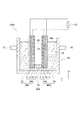
本実施形態の微生物燃料電池100Cは、図13に示すように、第二実施形態の電極複合体10Dを用いている。2枚の電極複合体10Dは、第一の導電体層1側に設けられた撥水層3同士が対向するように、カセット基材50を介して積層されている。カセット基材50は、撥水層3の外周部に沿うU字状の枠部材であり、上部が開口している。そして、図10に示す燃料電池ユニット60と同様に、カセット基材50の側面53は、撥水層3の外周部と接合されており、当該外周部からカセット基材50の内部に電解液70が漏出することを抑制できる。   As shown in FIG. 13, the microbial fuel cell 100 </ b> C of this embodiment uses the electrode assembly 10 </ b> D of the second embodiment. The two electrode composites 10D are laminated via the cassette base material 50 so that the water-repellent layers 3 provided on the first conductor layer 1 side face each other. The cassette base material 50 is a U-shaped frame member along the outer periphery of the water repellent layer 3, and the upper part is open. Similarly to the fuel cell unit 60 shown in FIG. 10, the side surface 53 of the cassette base material 50 is joined to the outer peripheral portion of the water-repellent layer 3, and the electrolytic solution 70 enters the cassette base material 50 from the outer peripheral portion. Can be prevented from leaking.

そして、図13に示すように、2枚の電極複合体10Dとカセット基材50とを積層してなる燃料電池ユニット60Cは、大気と連通した気相90が形成されるように、廃水槽80の内部に配置される。廃水槽80の内部には被処理液である電解液70が保持されており、電極複合体10Dは電解液70に浸漬されている。   As shown in FIG. 13, the fuel cell unit 60C formed by stacking the two electrode composites 10D and the cassette base material 50 has a wastewater tank 80 so that a gas phase 90 communicating with the atmosphere is formed. Placed inside. An electrolytic solution 70 that is a liquid to be treated is held inside the waste water tank 80, and the electrode assembly 10 </ b> D is immersed in the electrolytic solution 70.

上述のように、撥水層3は撥水性を有する。そのため、廃水槽80の内部に保持された電解液70とカセット基材50の内部とは隔てられ、2枚の電極複合体10Dとカセット基材50とにより形成された内部空間は気相90となっている。そして、図13に示すように、第一の導電体層1及び第二の導電体層5は、それぞれ外部回路110と電気的に接続されている。   As described above, the water repellent layer 3 has water repellency. Therefore, the electrolytic solution 70 held in the waste water tank 80 is separated from the inside of the cassette base material 50, and the internal space formed by the two electrode composites 10 </ b> D and the cassette base material 50 is a gas phase 90. It has become. As shown in FIG. 13, the first conductor layer 1 and the second conductor layer 5 are each electrically connected to the external circuit 110.

微生物燃料電池100Cにおいて、電極複合体10Dにおける第一の導電体層1は正極1Cであり、第二の導電体層5が負極20Bである。そして、多孔質体層2は電気絶縁体であるため、正極1Cと負極20Bとの間の短絡を防ぐことができる。正極1Cである第一の導電体層1には、触媒が担持されている。   In the microbial fuel cell 100C, the first conductor layer 1 in the electrode assembly 10D is the positive electrode 1C, and the second conductor layer 5 is the negative electrode 20B. And since the porous body layer 2 is an electrical insulator, the short circuit between the positive electrode 1C and the negative electrode 20B can be prevented. A catalyst is supported on the first conductor layer 1 which is the positive electrode 1C.

次に、本実施形態の微生物燃料電池100Cの作用について説明する。電極複合体10Dが電解液70に浸漬された場合、第一の導電体層1、第二の導電体層5及び多孔質体層2が電解液70に浸漬され、撥水層3の少なくとも一部が気相90に露出している。   Next, the operation of the microbial fuel cell 100C of this embodiment will be described. When the electrode composite 10D is immersed in the electrolytic solution 70, the first conductive layer 1, the second conductive layer 5, and the porous body layer 2 are immersed in the electrolytic solution 70, and at least one of the water repellent layer 3 is immersed. The part is exposed to the gas phase 90.

微生物燃料電池100Cの動作時には、負極20Bに、有機物及び窒素含有化合物の少なくとも一方を含有する電解液70を供給し、撥水層3に空気を供給する。そして、撥水層3を透過して正極1Cに酸素が拡散する。負極20Bでは、嫌気性微生物の触媒作用により、電解液70中の有機物及び窒素含有化合物の少なくとも一方から水素イオン及び電子を生成する。生成した水素イオンは、電極複合体10D中の多孔質体層2を透過して、正極1Cに到達する。また、生成した電子は負極20Bを通じて外部回路110へ移動し、さらに外部回路110から正極1Cに移動する。そして、水素イオン及び電子は、正極1C中の触媒の作用により酸素と結合し、水となって消費される。このとき、外部回路110によって、閉回路に流れる電気エネルギーを回収する。   During the operation of the microbial fuel cell 100C, the electrolytic solution 70 containing at least one of an organic substance and a nitrogen-containing compound is supplied to the negative electrode 20B, and air is supplied to the water repellent layer 3. Then, oxygen diffuses into the positive electrode 1C through the water repellent layer 3. In the negative electrode 20B, hydrogen ions and electrons are generated from at least one of the organic matter and the nitrogen-containing compound in the electrolytic solution 70 by the catalytic action of anaerobic microorganisms. The generated hydrogen ions pass through the porous body layer 2 in the electrode assembly 10D and reach the positive electrode 1C. Further, the generated electrons move to the external circuit 110 through the negative electrode 20B, and further move from the external circuit 110 to the positive electrode 1C. The hydrogen ions and electrons are combined with oxygen by the action of the catalyst in the positive electrode 1C and consumed as water. At this time, the electric energy flowing in the closed circuit is recovered by the external circuit 110.

このように、本実施形態に係る微生物燃料電池100Cは、電極複合体10Dを有している。電極複合体10Dは、第一の表面11aと、第一の表面11aと反対側の第二の表面11bとを備える、シート状の多孔質基材11を有する。また、電極複合体10Dは、多孔質基材11の厚さ方向Xにおいて、第一の表面11aから第二の表面11bに向かって多孔質基材11の一部に設けられた第一の導電体層1を有する。さらに電極複合体10Dは、多孔質基材11の厚さ方向Xにおいて、第二の表面11bから第一の表面11aに向かって多孔質基材11の一部に設けられた第二の導電体層5を有する。さらに、多孔質基材11は電気絶縁体である。そして、微生物燃料電池100Cにおいて、電極複合体10Dにおける第一の導電体層1を第一の電極(正極1C)とし、第二の導電体層5を第二の電極(負極20B)とする。上述のように、電極複合体10Dは、好気性微生物の侵入を防ぐため、正極1Cと撥水層との界面近傍における好気性微生物の増殖を抑制することができる。そのため、好気性微生物による酸素消費が抑制され、酸素還元反応を効率的に行うことが可能となる。   Thus, the microbial fuel cell 100C according to the present embodiment has the electrode assembly 10D. The electrode assembly 10D includes a sheet-like porous substrate 11 including a first surface 11a and a second surface 11b opposite to the first surface 11a. In addition, the electrode assembly 10D includes a first conductive member provided in a part of the porous substrate 11 from the first surface 11a toward the second surface 11b in the thickness direction X of the porous substrate 11. It has a body layer 1. Furthermore, the electrode assembly 10D is a second conductor provided in a part of the porous substrate 11 from the second surface 11b toward the first surface 11a in the thickness direction X of the porous substrate 11. Layer 5 is included. Furthermore, the porous substrate 11 is an electrical insulator. In the microbial fuel cell 100C, the first conductor layer 1 in the electrode assembly 10D is the first electrode (positive electrode 1C), and the second conductor layer 5 is the second electrode (negative electrode 20B). As described above, the electrode assembly 10D can suppress the growth of aerobic microorganisms in the vicinity of the interface between the positive electrode 1C and the water-repellent layer in order to prevent the entry of aerobic microorganisms. Therefore, oxygen consumption by aerobic microorganisms is suppressed, and oxygen reduction reaction can be performed efficiently.

以下、本実施形態を実施例によりさらに詳細に説明するが、本実施形態はこれら実施例に限定されるものではない。   Hereinafter, the present embodiment will be described in more detail by way of examples, but the present embodiment is not limited to these examples.

[実施例1]
実施例1では、図1に示す電極複合体を作製した。まず、多孔質基材として、厚さが1mmである不織布(日本不織布株式会社製「NLAT150」)を用意した。さらに、導電体層を形成するための導電性カーボン材料として、十条ケミカル株式会社製JELCON CH−8(高性能低抵抗カーボンペースト)を用意した。
[Example 1]
In Example 1, the electrode assembly shown in FIG. 1 was produced. First, as a porous substrate, a nonwoven fabric having a thickness of 1 mm (“NLAT150” manufactured by Nippon Nonwoven Fabric Co., Ltd.) was prepared. Furthermore, JELCON CH-8 (high performance low resistance carbon paste) manufactured by Jujo Chemical Co., Ltd. was prepared as a conductive carbon material for forming the conductor layer.

そして、導電性カーボン材料を不織布の表面に塗布した後、120℃のオーブン内にて15分間静置することで、本例の電極複合体を作製した。   And after apply | coating a conductive carbon material to the surface of a nonwoven fabric, the electrode composite of this example was produced by leaving still for 15 minutes in 120 degreeC oven.

[実施例2]
実施例2では、実施例1で得られた電極複合体を用いて図12に示す微生物燃料電池を作製した。
[Example 2]
In Example 2, the microbial fuel cell shown in FIG. 12 was produced using the electrode assembly obtained in Example 1.

(正極の作製)
まず、カーボンペーパー(燃料電池用電極基材TGP−H−120、東レ株式会社製)の一方の面にポリテトラフルオロエチレン(PTFE)分散液を塗工し、380℃で20分間加熱した。これにより、カーボンペーパーにポリテトラフルオロエチレン層を焼結させたエアカソードを得た。なお、ポリテトラフルオロエチレン分散液としては、Sigma−Aldrich社製の60wt% dispersion in H2Oを使用した。
(Preparation of positive electrode)
First, a polytetrafluoroethylene (PTFE) dispersion was applied to one surface of carbon paper (fuel cell electrode base material TGP-H-120, manufactured by Toray Industries, Inc.), and heated at 380 ° C. for 20 minutes. Thus, an air cathode obtained by sintering a polytetrafluoroethylene layer on carbon paper was obtained. As the polytetrafluoroethylene dispersion, 60 wt% dispersion in H 2 O manufactured by Sigma-Aldrich was used.

次に、カーボンペーパーの他方の面に、触媒インクを塗工した。なお、触媒インクは、Pt/C触媒、ナフィオン及びイオン交換水を混合することによって作製した。そして、当該触媒インクを、白金触媒が4mg/cmの目付となるように塗工した後、380℃で20分間乾燥することによって、本例の正極を作製した。なお、触媒インクにおけるPt/C触媒は、田中貴金属工業株式会社製「TEC10E70TPM」を使用した。また、ナフィオンは、シグマアルドリッチジャパン社製「Nafion perfluorinated resin solution」を使用した。 Next, the catalyst ink was applied to the other surface of the carbon paper. The catalyst ink was prepared by mixing a Pt / C catalyst, Nafion and ion exchange water. And after apply | coating the said catalyst ink so that a platinum catalyst may become a 4 mg / cm < 2 > basis weight, the positive electrode of this example was produced by drying at 380 degreeC for 20 minutes. Note that “TEC10E70TPM” manufactured by Tanaka Kikinzoku Kogyo Co., Ltd. was used as the Pt / C catalyst in the catalyst ink. Moreover, Nafion used "Nafion perfluorinated resin solution" by Sigma-Aldrich Japan.

(微生物燃料電池の作製)
実施例1で得られた電極複合体における導電性カーボン材料を担持した面と反対側の面に、上述の正極における触媒インクを塗工した面を積層することにより、電極接合体を作製した。さらに、2枚の電極接合体とU字型のカセット基材とを積層することにより、図12に示す燃料電池ユニットを得た。
(Production of microbial fuel cell)
An electrode assembly was prepared by laminating the surface coated with the catalyst ink in the positive electrode on the surface opposite to the surface carrying the conductive carbon material in the electrode composite obtained in Example 1. Furthermore, the fuel cell unit shown in FIG. 12 was obtained by laminating two electrode assemblies and a U-shaped cassette base material.

得られた燃料電池ユニットを、図12に示すように、容積が300ccの水槽の内部に設置し、当該水槽の内部に被処理液である人工廃水を流入させた。なお、微生物燃料電池の運転においては、スターチ等の有機性高分子を含む人工廃水を、負極に接触するように30日間にわたり連続的に流入させた。この際、人工廃水のBOD濃度は800mg/Lとした。人工廃水の流量は、負極の外形面積当たりのBOD負荷量であるBOD面積負荷が、16g/m/日になるように設定した。また、人工廃水中には、発電を担う嫌気性微生物として、土壌微生物を植種した。このようにして、本例の微生物燃料電池を得た。 As shown in FIG. 12, the obtained fuel cell unit was installed in a 300 cc water tank, and artificial waste water as a liquid to be treated was allowed to flow into the water tank. In the operation of the microbial fuel cell, artificial wastewater containing an organic polymer such as starch was continuously flowed over 30 days so as to be in contact with the negative electrode. At this time, the BOD concentration of the artificial wastewater was set to 800 mg / L. The flow rate of the artificial waste water was set so that the BOD area load, which is the BOD load amount per outer area of the negative electrode, was 16 g / m 2 / day. In addition, soil microorganisms were planted in the artificial wastewater as anaerobic microorganisms responsible for power generation. Thus, the microbial fuel cell of this example was obtained.

一般的に、微生物燃料電池は、正極と負極との間の距離が増大することで出力低下するため、従来は、いかに正極と負極との間の距離を縮小するかが重要であった。しかしながら、従来の技術常識に反して、多孔質体層を用いて正極と負極との間の距離をある程度増大させたほうが、長期的には出力が低下せず、高出力が維持できることが分かり、本実施形態の発明を完成するに至った。   In general, since the output of a microbial fuel cell decreases as the distance between the positive electrode and the negative electrode increases, conventionally, it has been important to reduce the distance between the positive electrode and the negative electrode. However, contrary to conventional technical common sense, it is understood that if the distance between the positive electrode and the negative electrode is increased to some extent using the porous body layer, the output does not decrease in the long term, and a high output can be maintained. The invention of this embodiment has been completed.

以上、本実施形態を説明したが、本実施形態はこれらに限定されるものではなく、本実施形態の要旨の範囲内で種々の変形が可能である。具体的には、図面において、電極複合体10,10A,10C,10D、及び正極1B、負極20、イオン移動層30は、矩形状に形成されている。しかし、これらの形状は特に限定されず、燃料電池の大きさ、並びに所望の発電性能等により任意に変更することができる。また、各層の面積も所望の機能が発揮できるならば任意に変更することができる。   Although the present embodiment has been described above, the present embodiment is not limited to these, and various modifications can be made within the scope of the gist of the present embodiment. Specifically, in the drawings, the electrode composites 10, 10A, 10C, 10D, the positive electrode 1B, the negative electrode 20, and the ion transfer layer 30 are formed in a rectangular shape. However, these shapes are not particularly limited, and can be arbitrarily changed depending on the size of the fuel cell and the desired power generation performance. Further, the area of each layer can be arbitrarily changed as long as a desired function can be exhibited.

1 第一の導電体層(導電体層)
1A 第一の電極
2 多孔質体層
3 撥水層
4 封止材料
5 第二の導電体層
10,10A,10B,10C,10D 電極複合体
11 多孔質基材
11a 第一の表面
11b 第二の表面
20 第二の電極
30 イオン移動層
100,100A,100B,100C 微生物燃料電池
1 First conductor layer (conductor layer)
DESCRIPTION OF SYMBOLS 1A 1st electrode 2 Porous body layer 3 Water repellent layer 4 Sealing material 5 2nd conductor layer 10, 10A, 10B, 10C, 10D Electrode complex 11 Porous base material 11a First surface 11b Second Surface 20 Second electrode 30 Ion transfer layer 100, 100A, 100B, 100C Microbial fuel cell

Claims (7)

第一の表面と、前記第一の表面と反対側の第二の表面とを備える、シート状の多孔質基材と、
前記多孔質基材の厚さ方向において、前記第一の表面から前記第二の表面に向かって前記多孔質基材の一部に設けられた第一の導電体層と、
を有する、電極複合体。
A sheet-like porous substrate comprising a first surface and a second surface opposite to the first surface;
In the thickness direction of the porous substrate, a first conductor layer provided on a part of the porous substrate from the first surface toward the second surface;
An electrode assembly.
前記多孔質基材の厚さは1.0mm〜50mmである、請求項1に記載の電極複合体。   The electrode assembly according to claim 1, wherein the porous substrate has a thickness of 1.0 mm to 50 mm. 前記多孔質基材は電気絶縁体である、請求項1又は2に記載の電極複合体。   The electrode composite according to claim 1, wherein the porous substrate is an electrical insulator. 前記多孔質基材の厚さ方向において、前記第二の表面から前記第一の表面に向かって前記多孔質基材の一部に設けられた第二の導電体層をさらに有する、請求項3に記載の電極複合体。   4. The apparatus further comprises a second conductor layer provided on a part of the porous substrate from the second surface toward the first surface in the thickness direction of the porous substrate. The electrode composite according to 1. 請求項1乃至3のいずれか一項に記載の電極複合体を用いた第一の電極と、
第二の電極と、
を有する、燃料電池。
A first electrode using the electrode composite according to any one of claims 1 to 3,
A second electrode;
A fuel cell.
前記電極複合体における前記第二の表面と、前記第二の電極との間に設けられ、プロトン透過性を有するイオン移動層をさらに備える、請求項5に記載の燃料電池。   The fuel cell according to claim 5, further comprising an ion transfer layer provided between the second surface of the electrode complex and the second electrode and having proton permeability. 請求項4に記載の電極複合体を有し、
前記電極複合体における第一の導電体層を第一の電極とし、第二の導電体層を第二の電極とする、燃料電池。
The electrode composite according to claim 4,
A fuel cell in which the first conductor layer in the electrode assembly is a first electrode, and the second conductor layer is a second electrode.
JP2016123443A 2016-06-22 2016-06-22 Electrode composite and fuel cell Pending JP2017228411A (en)

Priority Applications (1)

Application Number Priority Date Filing Date Title
JP2016123443A JP2017228411A (en) 2016-06-22 2016-06-22 Electrode composite and fuel cell

Applications Claiming Priority (1)

Application Number Priority Date Filing Date Title
JP2016123443A JP2017228411A (en) 2016-06-22 2016-06-22 Electrode composite and fuel cell

Publications (1)

Publication Number Publication Date
JP2017228411A true JP2017228411A (en) 2017-12-28

Family

ID=60891858

Family Applications (1)

Application Number Title Priority Date Filing Date
JP2016123443A Pending JP2017228411A (en) 2016-06-22 2016-06-22 Electrode composite and fuel cell

Country Status (1)

Country Link
JP (1) JP2017228411A (en)

Cited By (1)

* Cited by examiner, † Cited by third party
Publication number Priority date Publication date Assignee Title
JP2020004637A (en) * 2018-06-29 2020-01-09 東洋インキScホールディングス株式会社 Conductive substrate for enzyme power generation device, electrode for enzyme power generation device, and enzyme power generation device

Cited By (2)

* Cited by examiner, † Cited by third party
Publication number Priority date Publication date Assignee Title
JP2020004637A (en) * 2018-06-29 2020-01-09 東洋インキScホールディングス株式会社 Conductive substrate for enzyme power generation device, electrode for enzyme power generation device, and enzyme power generation device
JP7063147B2 (en) 2018-06-29 2022-05-09 東洋インキScホールディングス株式会社 Conductive substrate for enzyme power generation device, electrode for enzyme power generation device and enzyme power generation device

Similar Documents

Publication Publication Date Title
JP6368036B2 (en) Electrode structure and microbial fuel cell
JP6438115B2 (en) Microbial fuel cell system
WO2015122125A1 (en) Microbial fuel cell, microbial fuel cell system, and method for using microbial fuel cell
WO2017119419A1 (en) Gas diffusion electrode for microbial fuel cells and microbial fuel cell in which same is used
JPWO2016063455A1 (en) Electrode, fuel cell and water treatment device
US20200317543A1 (en) Purification unit and purification device
WO2018020807A1 (en) Microbial fuel cell
JP6438051B2 (en) Microbial fuel cell system
JP6643642B2 (en) Purification unit and purification device
US20190296381A1 (en) Microbial fuel cell and waste liquid treatment system
JP2017228411A (en) Electrode composite and fuel cell
JP2020087804A (en) Microbial fuel cell and liquid processing unit
WO2017145646A1 (en) Microbial fuel cell
JPWO2017175260A1 (en) Electrode, fuel cell and water treatment device
WO2017199475A1 (en) Liquid processing unit and liquid processing device
JP2019076833A (en) Liquid treatment system
WO2017195406A1 (en) Microbial fuel cell and liquid treatment unit using same
WO2018203455A1 (en) Liquid treatment system
JP2017148776A (en) Water treatment equipment
JP2017228410A (en) Electrode and microbial fuel cell
WO2019078002A1 (en) Liquid processing system
JP2020099850A (en) Liquid treatment system
WO2019078003A1 (en) Microbial fuel cell, liquid processing system, and liquid processing structure
WO2019064889A1 (en) Liquid treatment system
JP2017041372A (en) Microbial fuel cell and waste liquid processor