WO2015122125A1 - Microbial fuel cell, microbial fuel cell system, and method for using microbial fuel cell - Google Patents
Microbial fuel cell, microbial fuel cell system, and method for using microbial fuel cell Download PDFInfo
- Publication number
- WO2015122125A1 WO2015122125A1 PCT/JP2015/000285 JP2015000285W WO2015122125A1 WO 2015122125 A1 WO2015122125 A1 WO 2015122125A1 JP 2015000285 W JP2015000285 W JP 2015000285W WO 2015122125 A1 WO2015122125 A1 WO 2015122125A1
- Authority
- WO
- WIPO (PCT)
- Prior art keywords
- microbial fuel
- fuel cell
- negative electrode
- positive electrode
- electrode
- Prior art date
Links
Images


Classifications
-
- H—ELECTRICITY
- H01—ELECTRIC ELEMENTS
- H01M—PROCESSES OR MEANS, e.g. BATTERIES, FOR THE DIRECT CONVERSION OF CHEMICAL ENERGY INTO ELECTRICAL ENERGY
- H01M8/00—Fuel cells; Manufacture thereof
- H01M8/16—Biochemical fuel cells, i.e. cells in which microorganisms function as catalysts
-
- H—ELECTRICITY
- H01—ELECTRIC ELEMENTS
- H01M—PROCESSES OR MEANS, e.g. BATTERIES, FOR THE DIRECT CONVERSION OF CHEMICAL ENERGY INTO ELECTRICAL ENERGY
- H01M4/00—Electrodes
- H01M4/86—Inert electrodes with catalytic activity, e.g. for fuel cells
- H01M4/8605—Porous electrodes
-
- H—ELECTRICITY
- H01—ELECTRIC ELEMENTS
- H01M—PROCESSES OR MEANS, e.g. BATTERIES, FOR THE DIRECT CONVERSION OF CHEMICAL ENERGY INTO ELECTRICAL ENERGY
- H01M4/00—Electrodes
- H01M4/86—Inert electrodes with catalytic activity, e.g. for fuel cells
- H01M4/90—Selection of catalytic material
-
- H—ELECTRICITY
- H01—ELECTRIC ELEMENTS
- H01M—PROCESSES OR MEANS, e.g. BATTERIES, FOR THE DIRECT CONVERSION OF CHEMICAL ENERGY INTO ELECTRICAL ENERGY
- H01M4/00—Electrodes
- H01M4/86—Inert electrodes with catalytic activity, e.g. for fuel cells
- H01M4/96—Carbon-based electrodes
-
- H—ELECTRICITY
- H01—ELECTRIC ELEMENTS
- H01M—PROCESSES OR MEANS, e.g. BATTERIES, FOR THE DIRECT CONVERSION OF CHEMICAL ENERGY INTO ELECTRICAL ENERGY
- H01M8/00—Fuel cells; Manufacture thereof
- H01M8/02—Details
- H01M8/0202—Collectors; Separators, e.g. bipolar separators; Interconnectors
- H01M8/023—Porous and characterised by the material
- H01M8/0239—Organic resins; Organic polymers
-
- Y—GENERAL TAGGING OF NEW TECHNOLOGICAL DEVELOPMENTS; GENERAL TAGGING OF CROSS-SECTIONAL TECHNOLOGIES SPANNING OVER SEVERAL SECTIONS OF THE IPC; TECHNICAL SUBJECTS COVERED BY FORMER USPC CROSS-REFERENCE ART COLLECTIONS [XRACs] AND DIGESTS
- Y02—TECHNOLOGIES OR APPLICATIONS FOR MITIGATION OR ADAPTATION AGAINST CLIMATE CHANGE
- Y02E—REDUCTION OF GREENHOUSE GAS [GHG] EMISSIONS, RELATED TO ENERGY GENERATION, TRANSMISSION OR DISTRIBUTION
- Y02E60/00—Enabling technologies; Technologies with a potential or indirect contribution to GHG emissions mitigation
- Y02E60/30—Hydrogen technology
- Y02E60/50—Fuel cells
Definitions
- the present invention relates to a microbial fuel cell, a microbial fuel cell system, and a method for using the microbial fuel cell.
- a microbial fuel cell is a device that oxidizes and decomposes organic matter while converting the chemical energy of organic matter contained in wastewater into electrical energy by the catalytic action of microorganisms (metabolic reaction, biochemical conversion). That is, the microbial fuel cell produces electric energy directly from organic matter by the action of microorganisms. Therefore, the microbial fuel cell can be expected to improve the energy recovery efficiency as compared with a conventional energy recovery system that uses a conversion step from organic matter to biogas. Moreover, the microbial fuel cell can be used not only for power generation but also as an incidental facility for wastewater treatment, organic waste treatment, organic waste treatment, and the like.
- the microbial fuel cell includes, for example, a negative electrode that holds microorganisms and a positive electrode that contacts an oxidizing substance.
- a microbial fuel cell using a gas diffusion electrode as a positive electrode has attracted attention (for example, Patent Document 1). Since the gas diffusion electrode is porous, oxygen in the gas phase (for example, in the atmosphere) is supplied to the positive electrode. That is, hydrogen ions and electrons generated at the negative electrode can react with oxygen in the gas phase at the positive electrode.
- the performance mismatch between the electrodes in such a microbial fuel cell has not been noticed in the past, and the problems caused thereby have not been recognized.
- the mismatch in performance between the electrodes means that the material of the electrode having the higher performance is excessive, and therefore, it is required to eliminate the mismatch from the viewpoint of saving resources.
- the present invention has been made in view of such problems of the conventional technology. And the objective of this invention is providing the microbial fuel cell which can relieve the mismatch of the performance between a positive electrode and a negative electrode. A further object of the present invention is to provide a microbial fuel cell system using the microbial fuel cell and a method for using the microbial fuel cell.
- a microbial fuel cell includes an electrolyte containing an organic substance, an anode that holds anaerobic microorganisms, and is in contact with the electrolyte, a water-repellent layer, and a water-repellent layer. And a positive electrode including a gas diffusion layer stacked thereon. Then, to the area of the gas diffusion layers, the ratio of the area of the negative electrode and T 1, the electrolyte, to the maximum current density of the negative electrode of the negative electrode potential at the electrodes constituted based on the negative electrode and the positive electrode, the positive electrode in the electrode system the ratio of the maximum current density of the positive electrode at the potential and T 2.
- T 1 and T 2 are T 2 1/2 ⁇ T 1 ⁇ T 2 2 Satisfy the relationship.
- the method of using the microbial fuel cell according to the second aspect of the present invention includes an electrolytic solution containing an organic substance, an anaerobic microorganism, a negative electrode in contact with the electrolytic solution, a water repellent layer, and a water repellent layer. And a step of preparing a microbial fuel cell comprising a positive electrode comprising a gas diffusion layer. Then, to the area of the gas diffusion layers, the ratio of the area of the negative electrode and T 1, the electrolyte, to the maximum current density of the negative electrode of the negative electrode potential at the electrodes constituted based on the negative electrode and the positive electrode, the positive electrode in the electrode system the ratio of the maximum current density of the positive electrode at the potential and T 2.
- the usage method is that T 1 and T 2 are T 2 1/2 ⁇ T 1 ⁇ T 2 2 A process for operating the microbial fuel cell so as to satisfy the above relationship.
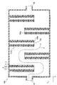
- FIG. 1 is a cross-sectional view schematically illustrating a microbial fuel cell according to the present embodiment and a microbial fuel cell system including the microbial fuel cell.
- Fig.2 (a) is sectional drawing which shows an example of the positive electrode which concerns on this embodiment
- FIG.2 (b) is a front view which shows the said positive electrode.
- FIG. 3 is a front view showing another example of the positive electrode according to the present embodiment.
- FIG. 4 is a front view showing another example of the positive electrode according to the present embodiment.
- FIG. 5 is a front view showing another example of the positive electrode according to the present embodiment.
- FIG. 6 is a side view showing another example of the microbial fuel cell system according to the present embodiment.
- FIG. 7 is a plan view showing another example of the microbial fuel cell system according to the present embodiment.
- the microbial fuel cell 1 includes an electrolyte solution 2, a negative electrode 3, a positive electrode 4, and a diaphragm 5.
- the electrolytic solution 2 contains an organic substance.
- the negative electrode 3 holds anaerobic microorganisms and is in contact with the electrolytic solution 2.
- the positive electrode 4 is composed of a gas diffusion electrode including a water repellent layer 41 and a gas diffusion layer 42 stacked on the water repellent layer 41.
- each of the area of the negative electrode 3 and the area of the gas diffusion layer 42 in this embodiment is not an actual area but a projected area.
- the maximum current density of the negative electrode 3 at the potential of the negative electrode 3 in the electrode system means that the negative electrode 3 is incorporated in the electrode system that governs the amount of energization of the system, and the potential of the negative electrode 3 is the microbial fuel cell 1.
- the maximum current density of the negative electrode 3 when the potential of the negative electrode 3 in the electrode system of FIG. This value is an index of the energization performance of the negative electrode 3.
- an electrode having a sufficiently large energization performance with respect to the negative electrode 3 is prepared as a counter electrode.
- the counter electrode is preferably an electrode that is stable during electrochemical measurement, such as a platinum electrode or a carbon electrode, and the counter electrode preferably has a sufficiently large area.
- the counter electrode may be made of the same material as the positive electrode 4 in the microbial fuel cell 1. For example, an Ag / AgCl electrode is prepared as a reference electrode.
- the negative electrode 3 and the counter electrode are disposed in the electrolytic solution.
- the electrolyte contains a supporting electrolyte at a concentration that does not interfere with electrochemical measurements.
- the negative electrode 3, the counter electrode, and the reference electrode are connected to a potentiostat, and the relationship between the potential of the negative electrode 3 and the current is obtained by linear sweep voltammetry or cyclic voltammetry. From this result, the current value when the potential of the negative electrode 3 is the potential in the electrode system of the microbial fuel cell 1 can be derived, and the current density of the negative electrode 3 can be calculated from the value.
- the area of the negative electrode 3 used in the calculation of the current density is a projected area in the surface direction of the negative electrode 3.
- the maximum current density of the positive electrode 4 at the potential of the positive electrode 4 in the electrode system means that the positive electrode 4 is incorporated in an electrode system that governs the amount of energization of the entire system, and the potential of the positive electrode 4 is It is the maximum current density of the positive electrode 4 when the potential of the positive electrode 4 in one electrode system. This value is an index of the energization performance of the positive electrode 4.
- an electrode having a sufficiently large energization performance with respect to the positive electrode 4 is prepared as a counter electrode.
- the counter electrode is preferably an electrode that is stable during electrochemical measurement, such as a platinum electrode or a carbon electrode, and the counter electrode preferably has a sufficiently large area.
- the counter electrode may be made of the same material as the negative electrode 3 in the microbial fuel cell 1. For example, an Ag / AgCl electrode is prepared as a reference electrode.
- the positive electrode 4 and the counter electrode are disposed in the electrolytic solution.
- the electrolyte contains a supporting electrolyte at a concentration that does not interfere with electrochemical measurements.
- the positive electrode 4, the counter electrode, and the reference electrode are connected to a potentiostat, and the relationship between the potential of the positive electrode 4 and the current is obtained by linear sweep voltammetry or cyclic voltammetry. From this result, the current value when the potential of the positive electrode 4 is the potential in the electrode system of the microbial fuel cell 1 can be derived, and the current density of the positive electrode 4 can be calculated from the value.
- the area of the positive electrode 4 used in the calculation of the current density is a projected area in the surface direction of the gas diffusion layer 42 in the positive electrode 4.
- the ratio of the area of the negative electrode 3 holding microorganisms to the area of the gas diffusion layer 42 of the positive electrode 4 is appropriate according to the performance of the negative electrode 3 and the positive electrode 4. Set to the correct value. For this reason, the mismatch in performance between the positive electrode 4 and the negative electrode 3 in the microbial fuel cell 1 can be alleviated. That is, when T 1 and T 2 satisfy the relationship of T 2 1/2 ⁇ T 1 , the performance of the positive electrode 4 in the microbial fuel cell 1 is suppressed from becoming excessively larger than the performance of the negative electrode 3. . Furthermore, the T 1 and T 2 is to satisfy the relationship of T 1 ⁇ T 2 2, the performance of the negative electrode 3 in the microbial fuel cell 1 becomes excessively large compared to the performance of the positive electrode 4 is suppressed.
- the area of the negative electrode 3 and the area of the gas diffusion layer 42 that are normally set to the same value are set to appropriate values, so that the positive electrode 4 and the negative electrode 3 in the microbial fuel cell 1 The performance mismatch can be alleviated.
- the microbial fuel cell 1 of the present embodiment includes the negative electrode 3, the positive electrode 4, the diaphragm 5, and the container 6 for holding them.
- a negative electrode 3, a positive electrode 4, and a diaphragm 5 are disposed in a container 6.
- the negative electrode 3, the diaphragm 5, and the positive electrode 4 are laminated in this order.
- the microbial fuel cell 1 is arranged such that the negative electrode 3 is in contact with one surface 5a of the diaphragm 5, and the positive electrode 4 is in contact with the surface 5b opposite to the surface 5a of the diaphragm 5.
- the gas diffusion layer 42 of the positive electrode 4 is in contact with the diaphragm 5, and the water-repellent layer 41 is exposed on the space 7 side where the gas phase is filled, as will be described later.
- the container 6 is configured to hold the electrolytic solution 2.
- the container 6 has a supply port 61 and a discharge port 62 formed therein.
- the electrolytic solution 2 is supplied from the outside of the microbial fuel cell 1 into the container 6 through the supply port 61, and the electrolytic solution 2 treated by the microbial fuel cell 1 is further discharged from the microbial fuel cell 1 through the discharge port 62. It is discharged outside.
- the electrolytic solution 2 contains an organic substance.
- the electrolytic solution 2 KH 2 PO 4, K 2 HPO 4, (NH 4) 2 SO 4, MgSO 4 ⁇ 7H 2 O, NaCl, CaCl 2 ⁇ 2H 2 O, Na 2 S 2 O 3 ⁇ 5H 2
- An electrolyte such as O may be contained.
- the material of the negative electrode 3 is preferably at least one of carbon and platinum, for example.
- the negative electrode 3 holds anaerobic microorganisms.
- the negative electrode 3 has a first surface 3a and a second surface 3b opposite to the first surface 3a.
- the first surface 3a faces the positive electrode 4 with the diaphragm 5 interposed therebetween.
- Anaerobic microorganisms are retained on the second surface 3b.
- the anaerobic microorganisms are hold
- the biofilm generally refers to a three-dimensional structure including a microbial population and an extracellular polymeric substance (EPS) produced by the microbial population.
- EPS extracellular polymeric substance
- the anaerobic microorganisms may be held on the negative electrode 3 regardless of the biofilm.
- the anaerobic microorganisms retained on the negative electrode 3 are preferably, for example, electricity producing bacteria having an extracellular electron transfer mechanism.
- examples of the anaerobic microorganism include Geobacter genus bacteria, Shewanella genus bacteria, Aeromonas genus bacteria, Geothrix genus bacteria, and Saccharomyces genus bacteria.
- the configuration and material of the diaphragm 5 are not particularly limited as long as hydrogen ions can move between the negative electrode 3 and the positive electrode 4.
- a proton conductive membrane such as a cation exchange membrane and an anion exchange membrane can be used.
- the diaphragm 5 which can move a hydrogen ion from the negative electrode 3 to the positive electrode 4 can be used, such as a nonwoven fabric, a glass fiber membrane, and a filter paper.
- the diaphragm 5 is preferably an ion exchange membrane or a solid electrolyte membrane, for example.
- Examples of the diaphragm 5 include fluorine resin ion exchange membranes having proton conductivity, such as Nafion (registered trademark, manufactured by DuPont) and Fileion (registered trademark, manufactured by Asahi Glass Co., Ltd.).
- the positive electrode 4 is composed of a gas diffusion electrode including a water-repellent layer 41 and a gas diffusion layer 42 stacked to be in contact with the water-repellent layer 41.
- the water repellent layer 41 is a layer having both water repellency and gas permeability.
- the water repellent layer 41 is configured to allow gas movement from the gas phase to the liquid phase while favorably separating the gas phase and the liquid phase in the electrochemical system in the microbial fuel cell 1. That is, the water repellent layer 41 is configured to transmit oxygen in the gas phase in the space 7 and move it to the gas diffusion layer 42.
- Such a water repellent layer 41 is preferably porous. In this case, the water repellent layer 41 can have high gas permeability.
- the gas diffusion layer 42 preferably includes, for example, a porous conductive material and a catalyst supported on the conductive material.
- the gas diffusion layer 42 may be composed of a porous and conductive catalyst.
- the negative electrode 3, the diaphragm 5 and the positive electrode 4 are disposed in the container 6. Further, a water repellent layer 41 in the positive electrode 4 is provided on the space 7 side. The surface of the water repellent layer 41 opposite to the gas diffusion layer 42 is exposed to the gas phase outside the container 6. Thus, oxygen in the gas phase can be supplied to the gas diffusion layer 42 through the water repellent layer 41. Further, the gas diffusion layer 42 in the positive electrode 4 is in contact with the diaphragm 5 so as to face the negative electrode 3 through the diaphragm 5.
- the microbial fuel cell system 10 of the present embodiment includes two microbial fuel cells 1. That is, the microbial fuel cell system 10 of the present embodiment preferably includes a plurality of microbial fuel cells 1.
- the two microbial fuel cells 1 are arranged such that the water repellent layers 41 face each other. That is, of the two microbial fuel cells 1, the water-repellent layer 41 of one microbial fuel cell 1 and the water-repellent layer 41 of the other microbial fuel cell 1 face each other with a gap therebetween. Thus, a space 7 that fills the gas phase is interposed between the two water repellent layers 41.
- the microbial fuel cell system 10 is configured such that the space 7 is opened to the outside air, or air is supplied to the space 7 from the outside air by, for example, a pump.
- an interval may be provided between the positive electrode 4 and the diaphragm 5, and an interval may be provided between the negative electrode 3 and the diaphragm 5.
- the microbial fuel cell 1 satisfies the relationship of T 2 1/2 ⁇ T 1 ⁇ T 2 2 .
- T 1 and T 2 are more preferable if the relationship of T 1 ⁇ T 2 1.5 is satisfied, and more preferable if the relationship of T 1 ⁇ T 2 1.2 is satisfied.
- T 1 and the T 2 It is also preferable to satisfy a relation of T 2 1 / 1.5 ⁇ T 1 , still more preferably satisfy the relationship of T 2 1 / 1.2 ⁇ T 1 .
- the area in the surface direction of the gas diffusion layer 42 is usually smaller than the area in the surface direction of the negative electrode 3.
- the area of the main surface 42a of the gas diffusion layer 42 is smaller than the area of the main surface (first surface 3a, second surface 3b) of the negative electrode 3. Therefore, the ratio of the area of the gas diffusion layer 42 to the area of the negative electrode 3 is preferably in the range of 0.1 to 0.9.
- the projected area of the water repellent layer 41 on the positive electrode 4 matches the projected area of the negative electrode 3.
- the projected area of the gas diffusion layer 42 is smaller than the projected area of the water repellent layer 41.
- the gas diffusion layer 42 is partially overlapped on the water repellent layer 41 as shown in FIG.
- the gas diffusion layer 42 includes a plurality of layers 421 that are stacked on the water repellent layer 41 and separated from each other in a direction perpendicular to the stacking direction of the negative electrode 3 and the positive electrode 4. preferable. Each of these layers 421 is overlaid on the surface of the water repellent layer 41 on the negative electrode 3 side.
- the layers 421 separated by the gas diffusion layer 42 are arranged at equal intervals with an interval. For this reason, it becomes difficult to produce the location where the distance between the negative electrode 3 and the gas diffusion layer 42 becomes excessively large. That is, when the negative electrode 3 and the gas diffusion layer 42 having a smaller area than the negative electrode 3 face each other, the negative electrode 3 includes a portion that does not face the gas diffusion layer 42. And when the gas diffusion layer 42 consists of a single layer, the location where the distance between the negative electrode 3 and the gas diffusion layer 42 becomes large excessively will arise.
- the plurality of layers 421 do not need to be completely separated, and may be partially connected via wiring, for example, in order to ensure electrical continuity between the layers 421.
- a holding body 43 that holds aerobic microorganisms may be overlaid on the water-repellent layer 41.
- aerobic microorganisms are held in a region of the water repellent layer 41 on the negative electrode 3 side where the gas diffusion layer 42 is not overlapped.
- a holding body 43 that holds aerobic microorganisms is superimposed on a region of the water repellent layer 41 where the gas diffusion layer 42 is not superimposed.
- the treatment of the electrolytic solution 2 can be efficiently performed by the action of the aerobic microorganism.
- a region for arranging the holding body 43 that holds aerobic microorganisms is secured on the water repellent layer 41. Therefore, the holding body 43 that holds aerobic microorganisms can be compactly arranged inside the microbial fuel cell 1. Furthermore, since the water repellent layer 41 has air permeability, oxygen for its growth can be sufficiently supplied to the aerobic microorganisms through the water repellent layer 41. For this reason, it is possible to achieve an efficient purification process of the electrolytic solution 2 without causing an increase in the size and the complexity of the structure of the microbial fuel cell 1.
- the aerobic microorganism examples include Escherichia bacterium, Escherichia bacterium, Pseudomonas bacterium, Bacillus bacterium, Bacillus bacterium.
- a nonwoven fabric-like or sponge-like structure can be used, for example.
- the holding body 43 can be made of, for example, one or more materials selected from the group consisting of polyethylene, polypropylene, polyethylene glycol, polyurethane, and polyvinyl alcohol.
- the electrolytic solution 2 is supplied into the container 6 and, for example, the negative electrode 3 and the positive electrode 4 are connected to an external circuit, so that the microbial fuel cell 1 is in a closed circuit state.
- the organic substance in the electrolyte solution 2 is decomposed
- the generated electrons flow from the negative electrode 3 to the external circuit, and the protons pass through the diaphragm 5 and reach the positive electrode 4.
- oxygen supplied from the gas phase reacts with protons and electrons and is reduced to produce water.
- the microbial fuel cell 1 has an electrolyte 2 containing an organic substance, an anaerobic microorganism, a negative electrode 3 in contact with the electrolyte 2, a water repellent layer 41, and a water repellent layer 41. And a positive electrode 4 including the gas diffusion layer 42. Then, to the area of the gas diffusion layer 42, to the maximum current density of the negative electrode in the ratio of the area of the negative electrode 3 and T 1, the potential of the negative electrode 3 in the constructed electrode system with electrolyte 2, an anode 3 and cathode 4, Let T 2 be the ratio of the maximum current density of the positive electrode at the potential of the positive electrode 4 in the electrode system. In this case, T 1 and T 2 satisfy the relationship of Expression (1). T 2 1/2 ⁇ T 1 ⁇ T 2 2 (1)
- the method of using the microbial fuel cell 1 is such that the electrolyte 2 containing organic matter, the anaerobic microorganisms are held, the negative electrode 3 in contact with the electrolyte, the water-repellent layer 41, and the water-repellent layer 41 are overlaid. It has the process of preparing the microbial fuel cell 1 provided with the positive electrode 4 provided with the gas diffusion layer 42.
- FIG. 1 the process of preparing the microbial fuel cell 1 provided with the positive electrode 4 provided with the gas diffusion layer 42.
- the usage method includes a step of operating the microbial fuel cell 1 so that T 1 and T 2 satisfy the relationship of the expression (1).
- the microbial fuel cell 1 is operated in a closed circuit state so that T 1 and T 2 satisfy the above relationship. Therefore, when using the microbial fuel cell 1 of the present embodiment, first, the composition of the waste water to be treated (electrolytic solution 2), for example, the type and concentration of each of the electrolyte and organic matter in the waste water is investigated and treated. Select the waste water (electrolytic solution 2) to be used. Next, the positive electrode 4 and the negative electrode 3 for the treatment of the wastewater are designed. That is, it is designed so that T 1 and T 2 satisfy a predetermined relationship according to the composition of the waste water (electrolytic solution 2).
- the composition of the waste water to be treated electrolytic solution 2
- the positive electrode 4 and the negative electrode 3 for the treatment of the wastewater are designed. That is, it is designed so that T 1 and T 2 satisfy a predetermined relationship according to the composition of the waste water (electrolytic solution 2).
- the performance of the positive electrode 4 in the microbial fuel cell 1 is suppressed from being excessively large compared to the performance of the negative electrode 3, and conversely, the performance of the negative electrode 3 is also suppressed from being excessively large compared to the performance of the positive electrode 4. Is done.
- the water repellent layer 41 and the gas diffusion layer 42 of the positive electrode 4 in the present embodiment will be described in more detail.
- the water repellent layer 41 is preferably a porous body having water repellency.
- the water repellent layer 41 can have high gas permeability.
- Such a water-repellent layer 41 may be made of, for example, one or more materials selected from the group consisting of polytetrafluoroethylene (PTFE), dimethylpolysiloxane (PDMS), polyethylene (PE), and polypropylene (PP). preferable.
- the gas diffusion layer 42 can be configured to include, for example, a porous conductive material and a catalyst supported on the conductive material.
- the gas diffusion layer 42 may be composed of a porous and conductive catalyst.
- the conductive material in the gas diffusion layer 42 can be composed of, for example, one or more materials selected from the group consisting of carbon-based substances, conductive polymers, semiconductors, and metals.
- the carbon-based material means a material containing carbon as a constituent component.
- Examples of carbon-based materials include, for example, graphite; activated carbon: carbon black, Vulcan (registered trademark) XC-72R, carbon powder such as acetylene black, furnace black, Denka black; graphite felt, carbon wool, carbon woven cloth, etc. Carbon fiber; carbon plate; carbon paper; and carbon disk.
- Examples of the carbon-based material also include fine-structured materials such as carbon nanotubes, carbon nanohorns, and carbon nanoclusters.
- Conductive polymer is a general term for conductive polymer compounds.
- the conductive polymer include aniline, aminophenol, diaminophenol, pyrrole, thiophene, paraphenylene, fluorene, furan, acetylene, or a polymer of two or more monomers having a structural unit as a constituent unit.
- examples of the conductive polymer include polyaniline, polyaminophenol, polydiaminophenol, polypyrrole, polythiophene, polyparaphenylene, polyfluorene, polyfuran, and polyacetylene.
- An example of the metal conductive material is a stainless mesh. In consideration of availability, cost, corrosion resistance, durability, and the like, the conductive material is preferably a carbon-based substance.
- the shape of the conductive material is preferably a powder shape or a fiber shape. Further, the conductive material may be supported by a support.
- the support means a member that itself has rigidity and can give a certain shape to the gas diffusion electrode.
- the support may be an insulator or a conductor.
- examples of the support include glass; plastic; synthetic rubber; ceramics; water-resistant or water-repellent treated paper; plant pieces such as wood pieces; animal pieces such as bone pieces and shells. It is done.
- Examples of the porous structure support include porous ceramics, porous plastics, and sponges.
- the support is a conductor
- examples of the support include carbon-based materials such as carbon paper, carbon fiber, and carbon rod; metal; conductive polymer.
- the support can also function as a current collector by disposing a conductive material carrying a carbon-based material on the surface of the support.
- the catalyst in the gas diffusion layer 42 is preferably a carbon-based material doped with, for example, metal atoms.
- metal atoms titanium, vanadium, chromium, manganese, iron, cobalt, nickel, copper, zirconium, niobium, molybdenum, ruthenium, rhodium, palladium, silver, hafnium, tantalum, tungsten, rhenium, osmium, iridium
- the carbon-based material exhibits excellent performance as a catalyst for particularly promoting the oxygen reduction reaction and the oxygen generation reaction. What is necessary is just to set suitably the quantity of the metal atom which carbonaceous material contains so that carbonaceous material may have the outstanding catalyst performance.
- the carbon-based material is further doped with one or more nonmetallic atoms selected from nitrogen, boron, sulfur, and phosphorus. What is necessary is just to set suitably the quantity of the nonmetallic atom doped by the carbonaceous material so that carbonaceous material may have the outstanding catalyst performance.
- the carbon-based material is based on a carbon source material such as graphite and amorphous carbon, for example, and the carbon source material is doped with a metal atom and one or more non-metal atoms selected from nitrogen, boron, sulfur and phosphorus. Can be obtained.
- a carbon source material such as graphite and amorphous carbon, for example, and the carbon source material is doped with a metal atom and one or more non-metal atoms selected from nitrogen, boron, sulfur and phosphorus. Can be obtained.
- the combination of metal atoms and nonmetal atoms doped in the carbon-based material is appropriately selected.
- the nonmetallic atom contains nitrogen and the metallic atom contains iron.
- the carbon-based material can have particularly excellent catalytic activity.
- the nonmetallic atom may be only nitrogen. Further, the metal atom may be only iron.
- the nonmetallic atom may contain nitrogen, and the metallic atom may contain at least one of cobalt and manganese. Also in this case, the carbon-based material can have a particularly excellent catalytic activity.
- the nonmetallic atom may be only nitrogen. Further, the metal atom may be only cobalt, only manganese, or only cobalt and manganese.
- the shape of the carbon-based material is not particularly limited.
- the carbon-based material may have a particulate shape or may have a sheet shape.
- the dimension of the carbon-based material having a sheet-like shape is not particularly limited.
- the carbon-based material may have a minute dimension.
- the carbon-based material having a sheet shape may be porous. It is preferable that the porous carbon-based material having a sheet shape has a shape such as a woven fabric shape or a nonwoven fabric shape. Such a carbon-based material can constitute the gas diffusion layer 42 even without a conductive material.
- the carbon-based material configured as a catalyst in the gas diffusion layer 42 can be prepared as follows. First, for example, a mixture containing a nonmetallic compound containing at least one nonmetal selected from the group consisting of nitrogen, boron, sulfur, and phosphorus, a metal compound, and a carbon source material is prepared. And this mixture is heated at the temperature of 800 degreeC or more and 1000 degrees C or less for 45 second or more and less than 600 second. Thereby, the carbonaceous material comprised as a catalyst can be obtained.
- the carbon source material for example, graphite or amorphous carbon can be used as described above.
- the metal compound is not particularly limited as long as it is a compound containing a metal atom capable of coordinating with a nonmetal atom doped in the carbon source material.
- Metal compounds include, for example, metal chlorides, nitrates, sulfates, bromides, iodides, fluorides, etc .; inorganic metal salts such as acetates; inorganic metal salt hydrates; and organic metal salts At least one selected from the group consisting of hydrates can be used.
- the metal compound preferably contains iron (III) chloride.
- the metal compound when graphite is doped with cobalt, the metal compound preferably contains cobalt chloride.
- the metal compound when the carbon source material is doped with manganese, the metal compound preferably contains manganese acetate.
- the amount of the metal compound used is preferably determined so that, for example, the ratio of the metal atom in the metal compound to the carbon source material is in the range of 5 to 30% by mass, and further this ratio is 5 to 20% by mass. More preferably, it is determined to be within the range.
- the nonmetallic compound is preferably at least one nonmetallic compound selected from the group consisting of nitrogen, boron, sulfur and phosphorus.
- Non-metallic compounds include, for example, pentaethylenehexamine, ethylenediamine, tetraethylenepentamine, triethylenetetramine, ethylenediamine, octylboronic acid, 1,2-bis (diethylphosphinoethane), triphenyl phosphite, benzyldisal
- At least one compound selected from the group consisting of fido can be used.
- the amount of the nonmetallic compound used is appropriately set according to the amount of the nonmetallic atom doped into the carbon source material.
- the amount of the nonmetallic compound used is preferably determined so that the molar ratio of the metal atom in the metal compound to the nonmetallic atom in the nonmetallic compound is in the range of 1: 1 to 1: 2. More preferably, it is determined to be within the range of 1: 1.5 to 1: 1.8.
- a mixture containing a nonmetallic compound, a metal compound, and a carbon source material when preparing a carbon-based material configured as a catalyst is obtained, for example, as follows. First, a carbon source material, a metal compound, and a nonmetal compound are mixed, and if necessary, a solvent such as ethanol is added to adjust the total amount. These are further dispersed by an ultrasonic dispersion method. Subsequently, after heating them at an appropriate temperature (for example, 60 ° C.), the mixture is dried to remove the solvent. Thereby, the mixture containing a nonmetallic compound, a metal compound, and a carbon source raw material is obtained.
- the obtained mixture is heated, for example, under a reducing atmosphere or an inert gas atmosphere.
- a non-metallic atom is doped to a carbon source raw material, and also a metallic atom is doped by the coordinate bond of a non-metallic atom and a metallic atom.
- the heating temperature is preferably in the range of 800 ° C. to 1000 ° C.
- the heating time is preferably in the range of 45 seconds to less than 600 seconds. Since the heating time is short, the carbon-based material is efficiently produced, and the catalytic activity of the carbon-based material is further increased.
- the temperature rising rate of the mixture at the start of heating is preferably 50 ° C./s or more. Such rapid heating further improves the catalytic activity of the carbonaceous material.
- the carbon-based material may be further acid cleaned.
- the carbon-based material may be dispersed in pure water with a homogenizer for 30 minutes, and then the carbon-based material may be placed in 2M sulfuric acid and stirred at 80 ° C. for 3 hours. In this case, elution of the metal component from the carbon-based material can be suppressed.
- T 1 and T 2 must satisfy the relationship of the formula (1) in the microbial fuel cell 1A according to the present embodiment.
- the gas diffusion layer 42 is partially overlapped with a part on the water-repellent layer 41, similarly to the above-described positive electrode 4A.
- the gas diffusion layer 42 is preferably provided partially on the positive electrode 4B. That is, it is preferable that the gas diffusion layer 42 laminated on the water repellent layer 41 is partially provided in the upper part in the vertical direction Y and the gas diffusion layer 42 is not provided in the lower part.
- the power generation performance is higher in the upper part than in the lower part of the microbial fuel cell 1A. There is a high tendency.
- the gas diffusion layer 42 is partially provided on the positive electrode 4B, and the negative electrode 3 is also provided on the positive electrode 4B in accordance with the gas diffusion layer 42.
- the gas diffusion layer 42 and the negative electrode 3 are not provided in the lower part where the power generation performance is degraded, it is possible to avoid a decrease in the power generation performance of the entire microbial fuel cell 1A.
- the usage-amount of the gas diffusion layer 42 and the negative electrode 3 can be reduced, it becomes possible to reduce the cost of the microbial fuel cell system 10A whole.
- the gas diffusion layer 42 is provided on the upper portion of the positive electrode 4B” means that the gas diffusion layer 42 is provided on the lower side 41a of the water repellent layer 41 in the vertical direction Y as shown in FIG. It means not being done.
- the gas diffusion layer 42 is overlaid on the water repellent layer 41 and is perpendicular to the stacking direction of the gas diffusion layer 42 and the water repellent layer 41.
- it includes a plurality of layers 421 that are separated from each other in the direction.
- the layers 421 separated from the gas diffusion layer 42 are arranged at equal intervals with an interval. For this reason, it becomes difficult to produce the location where the distance between the negative electrode 3 and the gas diffusion layer 42 becomes excessively large. As a result, the reaction efficiency in the microbial fuel cell system 10A can be improved.
- the plurality of layers 421 may be provided in the upper part of the positive electrode 4 ⁇ / b> C and separated in the plane direction X perpendicular to the vertical direction Y, as shown in FIG. 4. Further, as shown in FIG. 5, the plurality of layers 421 may be provided in the upper part of the positive electrode 4 ⁇ / b> D and arranged in a state separated along the vertical direction Y.
- a gas diffusion layer 42 is partially provided on the upper part of the positive electrode, and a holding body 43 that holds aerobic microorganisms is provided on the lower part of the positive electrode on which the gas diffusion layer 42 is not provided. It is preferable to provide it. That is, as shown in FIG. 6, the gas diffusion layer 42 is provided in the upper part of the positive electrode where the power generation efficiency is high, and the negative electrode 3 and the diaphragm 5 are provided in corresponding positions. Then, by providing the holding body 43 that holds the aerobic microorganisms in the lower portion where the power generation efficiency is low, it is possible to further increase the power generation efficiency and achieve more efficient purification treatment of the electrolytic solution 2.
- the water repellent layer 41 has air permeability, oxygen for its growth can be sufficiently supplied to the aerobic microorganism through the water repellent layer 41. For this reason, the purification process of the electrolyte solution 2 can be performed without causing the enlargement of the microbial fuel cell 1 and the complexity of the structure.
- the holding body 43 that holds the aerobic microorganism is preferably provided below the positive electrodes 4B, 4C, and 4D.
- the gas diffusion layer 42 may be disposed in the space between the separated layers 421 in the positive electrodes 4C and 4D as well as in the lower portion of the positive electrode. Since there is almost no difference in the purification performance of the holding body 43 between the upper part and the lower part of the positive electrode, the purification efficiency of the electrolytic solution 2 can be increased by being disposed between the layers 421.
- the microbial fuel cell system 10A of the present embodiment includes a plurality of microbial fuel cells 1A including the positive electrodes 4B, 4C, and 4D described above. Further, as shown in FIG. 6, in the microbial fuel cell system 10A, as in the first embodiment, the two microbial fuel cells 1 are arranged so that the water-repellent layers 41 face each other. Therefore, a space 7 that fills the gas phase is interposed between the two water repellent layers 41.
- the microbial fuel cell system 10A is also configured such that the space 7 is opened to the outside air, or air is supplied from the outside air to the space 7 by, for example, a pump.
- the microbial fuel cell system 10A includes a plurality of microbial fuel cell groups 100 including microbial fuel cells 1A arranged such that the water repellent layers 41 face each other.
- the microbial fuel cell system 10 ⁇ / b> A arranges a plurality of microbial fuel cell groups 100 along the stacking direction Z.
- the electrolytic solution 2 is also supplied into the container 6 through the supply port 61 along the stacking direction Z, and is discharged to the outside of the container 6 through the discharge port 62.
- the microbial fuel cell group 100 is preferably arranged so that the electrolyte 2 flows in a wave shape inside the container 6 as indicated by an arrow A in FIG.
- the plurality of microbial fuel cell groups 100 are arranged along the stacking direction Z.
- the plurality of microbial fuel cell groups 100 are arranged such that the side surfaces 100 a of the microbial fuel cell group 100 are alternately in contact with the left wall 6 a and the right wall 6 b of the container 6.
- the contact efficiency between the electrolyte 2, the negative electrode 3, and the holding body 43 can be increased, and as a result, the power generation efficiency and the purification efficiency can be further improved. Become.
- the arrangement of the microbial fuel cell group 100 shown in FIG. 6 and FIG. 7 is not limited to the case of the microbial fuel cell 1A of the second embodiment, but in the case of the microbial fuel cell 1 of the first embodiment. You may apply.
- the microbial fuel cell 1 of the first embodiment and the microbial fuel cell 1A of the second embodiment may be arbitrarily combined.
- the positive electrode and the negative electrode in the microbial fuel cell by setting the ratio of the area of the negative electrode holding microorganisms to the area of the gas diffusion layer of the positive electrode to an appropriate value according to the performance of the negative electrode and the positive electrode, the positive electrode and the negative electrode in the microbial fuel cell The performance mismatch between can be alleviated.
Landscapes
- Chemical & Material Sciences (AREA)
- Electrochemistry (AREA)
- General Chemical & Material Sciences (AREA)
- Chemical Kinetics & Catalysis (AREA)
- Life Sciences & Earth Sciences (AREA)
- Engineering & Computer Science (AREA)
- Manufacturing & Machinery (AREA)
- Sustainable Development (AREA)
- Sustainable Energy (AREA)
- Biochemistry (AREA)
- Microbiology (AREA)
- Materials Engineering (AREA)
- Inert Electrodes (AREA)
- Fuel Cell (AREA)
Abstract
Description
T2 1/2≦T1≦T2 2
の関係を満たす。 In order to solve the above-described problems, a microbial fuel cell according to the first aspect of the present invention includes an electrolyte containing an organic substance, an anode that holds anaerobic microorganisms, and is in contact with the electrolyte, a water-repellent layer, and a water-repellent layer. And a positive electrode including a gas diffusion layer stacked thereon. Then, to the area of the gas diffusion layers, the ratio of the area of the negative electrode and T 1, the electrolyte, to the maximum current density of the negative electrode of the negative electrode potential at the electrodes constituted based on the negative electrode and the positive electrode, the positive electrode in the electrode system the ratio of the maximum current density of the positive electrode at the potential and T 2. In this case, T 1 and T 2 are
T 2 1/2 ≦ T 1 ≦ T 2 2
Satisfy the relationship.
T2 1/2≦T1≦T2 2
の関係を満たすように、微生物燃料電池を稼働させる工程を有する。 The method of using the microbial fuel cell according to the second aspect of the present invention includes an electrolytic solution containing an organic substance, an anaerobic microorganism, a negative electrode in contact with the electrolytic solution, a water repellent layer, and a water repellent layer. And a step of preparing a microbial fuel cell comprising a positive electrode comprising a gas diffusion layer. Then, to the area of the gas diffusion layers, the ratio of the area of the negative electrode and T 1, the electrolyte, to the maximum current density of the negative electrode of the negative electrode potential at the electrodes constituted based on the negative electrode and the positive electrode, the positive electrode in the electrode system the ratio of the maximum current density of the positive electrode at the potential and T 2. In this case, the usage method is that T 1 and T 2 are
T 2 1/2 ≦ T 1 ≦ T 2 2
A process for operating the microbial fuel cell so as to satisfy the above relationship.
本実施形態に係る微生物燃料電池1は、図1に示すように、電解液2、負極3、正極4、及び隔膜5を備える。電解液2は有機物を含んでいる。負極3は、嫌気性微生物を保持し、電解液2に接触している。そして、正極4は、撥水層41と、撥水層41上に重ねられているガス拡散層42とを備えるガス拡散電極からなる。 [First embodiment]
As shown in FIG. 1, the
T2 1/2≦T1≦T2 2 (1) Then, the ratio of the area in the surface direction of the
T 2 1/2 ≦ T 1 ≦ T 2 2 (1)
T2 1/2≦T1≦T2 2 (1) The
T 2 1/2 ≦ T 1 ≦ T 2 2 (1)
T2 1/2≦T1≦T2 2 (1) Also, the method of using the
T 2 1/2 ≦ T 1 ≦ T 2 2 (1)
次に、第二実施形態に係る微生物燃料電池1A、微生物燃料電池システム10Aについて、図面に基づき詳細に説明する。なお、第一実施形態と同一構成には同一符号を付し、重複する説明は省略する。 [Second Embodiment]
Next, the
2 電解液
3 負極
4,4A,4B,4C,4D 正極
6 容器
7 空間
10,10A,10B 微生物燃料電池システム
41 撥水層
42 ガス拡散層
100 微生物燃料電池群 DESCRIPTION OF
Claims (11)
- 有機物を含む電解液と、
嫌気性微生物を保持し、前記電解液に接する負極と、
撥水層と、前記撥水層上に重ねられているガス拡散層とを備える正極と、
を備え、
前記ガス拡散層の面積に対する、前記負極の面積の比をT1とし、前記電解液、前記負極及び前記正極で構成される電極系における前記負極の電位での前記負極の最大電流密度に対する、前記電極系における前記正極の電位での前記正極の最大電流密度の比をT2とした場合、T1及びT2が、
T2 1/2≦T1≦T2 2
の関係を満たす微生物燃料電池。 An electrolyte containing organic matter;
A negative electrode that holds anaerobic microorganisms and is in contact with the electrolyte;
A positive electrode comprising a water repellent layer and a gas diffusion layer overlaid on the water repellent layer;
With
To the area of the gas diffusion layer, wherein the ratio of the area of the negative electrode and T 1, the electrolyte, the relative maximum current density of the negative electrode at the potential of the negative electrode in formed electrode system at the negative electrode and the positive electrode, the When the ratio of the maximum current density of the positive electrode at the potential of the positive electrode in the electrode system is T 2 , T 1 and T 2 are
T 2 1/2 ≦ T 1 ≦ T 2 2
Microbial fuel cell that satisfies the relationship. - 前記撥水層上に、好気性微生物を保持する保持体が重ねられている請求項1に記載の微生物燃料電池。 The microbial fuel cell according to claim 1, wherein a holder for holding aerobic microorganisms is stacked on the water repellent layer.
- 前記ガス拡散層は、前記撥水層上に部分的に重ねられている請求項1又は2に記載の微生物燃料電池。 The microbial fuel cell according to claim 1 or 2, wherein the gas diffusion layer is partially overlapped on the water repellent layer.
- 前記ガス拡散層は、前記撥水層上に重ねられ、かつ、前記負極及び前記正極の積層方向に垂直な方向に互いに分離している複数の層を含む請求項1乃至3のいずれか一項に記載の微生物燃料電池。 4. The gas diffusion layer according to claim 1, wherein the gas diffusion layer includes a plurality of layers stacked on the water repellent layer and separated from each other in a direction perpendicular to a stacking direction of the negative electrode and the positive electrode. A microbial fuel cell according to claim 1.
- 前記ガス拡散層は、前記正極の上部に部分的に設けられている請求項1乃至4のいずれか一項に記載の微生物燃料電池。 The microbial fuel cell according to any one of claims 1 to 4, wherein the gas diffusion layer is partially provided on an upper portion of the positive electrode.
- 前記ガス拡散層は、多孔質な導電性材料と、前記導電性材料に担持されている触媒とを備える請求項1乃至3のいずれか一項に記載の微生物燃料電池。 The microbial fuel cell according to any one of claims 1 to 3, wherein the gas diffusion layer includes a porous conductive material and a catalyst supported on the conductive material.
- 前記触媒が、金属原子がドープされている炭素系材料である請求項6に記載の微生物燃料電池。 The microbial fuel cell according to claim 6, wherein the catalyst is a carbon-based material doped with metal atoms.
- 請求項1乃至7のいずれか一項に記載の微生物燃料電池を複数備える微生物燃料電池システム。 A microbial fuel cell system comprising a plurality of the microbial fuel cells according to any one of claims 1 to 7.
- 二つの前記微生物燃料電池は、前記撥水層が互いに対向するように配置される請求項8に記載の微生物燃料電池システム。 The microbial fuel cell system according to claim 8, wherein the two microbial fuel cells are arranged such that the water-repellent layers face each other.
- 前記撥水層が互いに対向するように配置された前記微生物燃料電池からなる微生物燃料電池群を複数備える請求項9に記載の微生物燃料電池システム。 The microbial fuel cell system according to claim 9, comprising a plurality of microbial fuel cell groups comprising the microbial fuel cells arranged so that the water repellent layers face each other.
- 有機物を含む電解液と、嫌気性微生物を保持し、前記電解液に接する負極と、撥水層と、前記撥水層上に重ねられているガス拡散層とを備える正極とを備える微生物燃料電池を準備する工程と、
前記ガス拡散層の面積に対する、前記負極の面積の比をT1とし、前記電解液、前記負極及び前記正極で構成される電極系における前記負極の電位での前記負極の最大電流密度に対する、前記電極系における前記正極の電位での前記正極の最大電流密度の比をT2とした場合、T1及びT2が、
T2 1/2≦T1≦T2 2
の関係を満たすように、前記微生物燃料電池を稼働させる工程と、
を有する微生物燃料電池の使用方法。 Microbial fuel cell comprising an electrolyte containing an organic substance, a negative electrode holding anaerobic microorganisms and in contact with the electrolyte, a water repellent layer, and a positive electrode provided with a gas diffusion layer overlaid on the water repellent layer The process of preparing
To the area of the gas diffusion layer, wherein the ratio of the area of the negative electrode and T 1, the electrolyte, the relative maximum current density of the negative electrode at the potential of the negative electrode in formed electrode system at the negative electrode and the positive electrode, the When the ratio of the maximum current density of the positive electrode at the potential of the positive electrode in the electrode system is T 2 , T 1 and T 2 are
T 2 1/2 ≦ T 1 ≦ T 2 2
A step of operating the microbial fuel cell so as to satisfy the relationship of
Use of a microbial fuel cell having
Priority Applications (4)
| Application Number | Priority Date | Filing Date | Title |
|---|---|---|---|
| US15/117,225 US20160351937A1 (en) | 2014-02-13 | 2015-01-22 | Microbial fuel cell, microbial fuel cell system, and method for using microbial fuel cell |
| JP2015562716A JPWO2015122125A1 (en) | 2014-02-13 | 2015-01-22 | Microbial fuel cell, microbial fuel cell system, and method of using microbial fuel cell |
| EP15749515.1A EP3107141A4 (en) | 2014-02-13 | 2015-01-22 | Microbial fuel cell, microbial fuel cell system, and method for using microbial fuel cell |
| CN201580008113.9A CN105981208A (en) | 2014-02-13 | 2015-01-22 | Microbial fuel cell, microbial fuel cell system, and method for using microbial fuel cell |
Applications Claiming Priority (2)
| Application Number | Priority Date | Filing Date | Title |
|---|---|---|---|
| JP2014-025391 | 2014-02-13 | ||
| JP2014025391 | 2014-02-13 |
Publications (1)
| Publication Number | Publication Date |
|---|---|
| WO2015122125A1 true WO2015122125A1 (en) | 2015-08-20 |
Family
ID=53799878
Family Applications (1)
| Application Number | Title | Priority Date | Filing Date |
|---|---|---|---|
| PCT/JP2015/000285 WO2015122125A1 (en) | 2014-02-13 | 2015-01-22 | Microbial fuel cell, microbial fuel cell system, and method for using microbial fuel cell |
Country Status (5)
| Country | Link |
|---|---|
| US (1) | US20160351937A1 (en) |
| EP (1) | EP3107141A4 (en) |
| JP (1) | JPWO2015122125A1 (en) |
| CN (1) | CN105981208A (en) |
| WO (1) | WO2015122125A1 (en) |
Cited By (8)
| Publication number | Priority date | Publication date | Assignee | Title |
|---|---|---|---|---|
| JP2016024865A (en) * | 2014-07-16 | 2016-02-08 | 積水化学工業株式会社 | Electrode module for microbial fuel cell and microbial fuel cell |
| JP2017048094A (en) * | 2015-09-04 | 2017-03-09 | パナソニック株式会社 | Carbon-based material, and electrode and microbial fuel cell provided therewith |
| WO2017149633A1 (en) * | 2016-03-01 | 2017-09-08 | 株式会社日立製作所 | Water treatment device, and electroconductive porous carbon material for use therein |
| WO2017175260A1 (en) * | 2016-04-08 | 2017-10-12 | パナソニック株式会社 | Electrode, fuel cell and water treatment device |
| JP2018045985A (en) * | 2016-09-18 | 2018-03-22 | 東莞理工学院 | Method for manufacturing microbial fuel cell by molybdenum nitride cathode |
| CN108140861A (en) * | 2015-10-09 | 2018-06-08 | 凯米罗总公司 | For controlling the method for the operation of microbial fuel cell unit and microbial fuel cell unit |
| JP6358352B1 (en) * | 2017-03-24 | 2018-07-18 | 栗田工業株式会社 | Microbial power generation apparatus and microbial power generation method |
| CN108604699A (en) * | 2016-02-26 | 2018-09-28 | 松下电器产业株式会社 | Microbiological fuel cell |
Families Citing this family (2)
| Publication number | Priority date | Publication date | Assignee | Title |
|---|---|---|---|---|
| EP3522276A4 (en) * | 2016-09-30 | 2019-10-02 | Panasonic Corporation | Carbon-based material, electrode provided with same and microbial fuel cell |
| CN108206288B (en) * | 2017-12-29 | 2021-06-01 | 哈尔滨工业大学 | Large-aperture porous spacing structure for biological cathode microbial electrochemical system |
Citations (3)
| Publication number | Priority date | Publication date | Assignee | Title |
|---|---|---|---|---|
| WO2007037261A1 (en) * | 2005-09-28 | 2007-04-05 | Ebara Corporation | Biological power plant, and method of treating organic solid contaminant-containing waste, method of treating organic high molecular substance-containing liquid waste and method of treating organic substance-containing liquid waste by using the biological power plant, and apparatus for conducting these methods |
| JP2010033823A (en) * | 2008-07-28 | 2010-02-12 | Kurita Water Ind Ltd | Microorganism electric generation device |
| JP2011065875A (en) * | 2009-09-17 | 2011-03-31 | Kurita Water Ind Ltd | Microorganism power generation device |
Family Cites Families (6)
| Publication number | Priority date | Publication date | Assignee | Title |
|---|---|---|---|---|
| JP3898454B2 (en) * | 2001-03-06 | 2007-03-28 | シャープ株式会社 | Polymer electrolyte fuel cell |
| US7368190B2 (en) * | 2002-05-02 | 2008-05-06 | Abbott Diabetes Care Inc. | Miniature biological fuel cell that is operational under physiological conditions, and associated devices and methods |
| CN101317297A (en) * | 2005-09-28 | 2008-12-03 | 株式会社荏原制作所 | Biological power plant, and method of treating organic solid contaminant-containing waste, method of treating organic high molecular substance-containing liquid waste and method of treating organic su |
| US20090017512A1 (en) * | 2006-12-06 | 2009-01-15 | May Harold D | Apparatus and methods for the production of ethanol, hydrogen and electricity |
| JP5458489B2 (en) * | 2007-12-21 | 2014-04-02 | 栗田工業株式会社 | Microbial power generator |
| US9074198B2 (en) * | 2009-05-27 | 2015-07-07 | University Of Massachusetts | Geobacteraceae strains and methods |
-
2015
- 2015-01-22 CN CN201580008113.9A patent/CN105981208A/en active Pending
- 2015-01-22 US US15/117,225 patent/US20160351937A1/en not_active Abandoned
- 2015-01-22 WO PCT/JP2015/000285 patent/WO2015122125A1/en active Application Filing
- 2015-01-22 EP EP15749515.1A patent/EP3107141A4/en not_active Withdrawn
- 2015-01-22 JP JP2015562716A patent/JPWO2015122125A1/en active Pending
Patent Citations (3)
| Publication number | Priority date | Publication date | Assignee | Title |
|---|---|---|---|---|
| WO2007037261A1 (en) * | 2005-09-28 | 2007-04-05 | Ebara Corporation | Biological power plant, and method of treating organic solid contaminant-containing waste, method of treating organic high molecular substance-containing liquid waste and method of treating organic substance-containing liquid waste by using the biological power plant, and apparatus for conducting these methods |
| JP2010033823A (en) * | 2008-07-28 | 2010-02-12 | Kurita Water Ind Ltd | Microorganism electric generation device |
| JP2011065875A (en) * | 2009-09-17 | 2011-03-31 | Kurita Water Ind Ltd | Microorganism power generation device |
Non-Patent Citations (1)
| Title |
|---|
| See also references of EP3107141A4 * |
Cited By (14)
| Publication number | Priority date | Publication date | Assignee | Title |
|---|---|---|---|---|
| JP2016024865A (en) * | 2014-07-16 | 2016-02-08 | 積水化学工業株式会社 | Electrode module for microbial fuel cell and microbial fuel cell |
| JP2017048094A (en) * | 2015-09-04 | 2017-03-09 | パナソニック株式会社 | Carbon-based material, and electrode and microbial fuel cell provided therewith |
| CN108140861A (en) * | 2015-10-09 | 2018-06-08 | 凯米罗总公司 | For controlling the method for the operation of microbial fuel cell unit and microbial fuel cell unit |
| CN108604699A (en) * | 2016-02-26 | 2018-09-28 | 松下电器产业株式会社 | Microbiological fuel cell |
| US20190020048A1 (en) * | 2016-02-26 | 2019-01-17 | Panasonic Corporation | Microbial fuel cell |
| EP3422451A4 (en) * | 2016-02-26 | 2019-02-06 | Panasonic Corporation | Microbial fuel cell |
| JP6224269B1 (en) * | 2016-03-01 | 2017-11-01 | 株式会社日立製作所 | Water treatment apparatus and conductive porous carbon material used therefor |
| WO2017149633A1 (en) * | 2016-03-01 | 2017-09-08 | 株式会社日立製作所 | Water treatment device, and electroconductive porous carbon material for use therein |
| WO2017175260A1 (en) * | 2016-04-08 | 2017-10-12 | パナソニック株式会社 | Electrode, fuel cell and water treatment device |
| JPWO2017175260A1 (en) * | 2016-04-08 | 2019-02-14 | パナソニック株式会社 | Electrode, fuel cell and water treatment device |
| JP2018045985A (en) * | 2016-09-18 | 2018-03-22 | 東莞理工学院 | Method for manufacturing microbial fuel cell by molybdenum nitride cathode |
| JP6358352B1 (en) * | 2017-03-24 | 2018-07-18 | 栗田工業株式会社 | Microbial power generation apparatus and microbial power generation method |
| WO2018173327A1 (en) * | 2017-03-24 | 2018-09-27 | 栗田工業株式会社 | Microbial power generation device |
| JP2018163751A (en) * | 2017-03-24 | 2018-10-18 | 栗田工業株式会社 | Microorganism power generation device and microorganism power generation method |
Also Published As
| Publication number | Publication date |
|---|---|
| JPWO2015122125A1 (en) | 2017-03-30 |
| US20160351937A1 (en) | 2016-12-01 |
| EP3107141A1 (en) | 2016-12-21 |
| CN105981208A (en) | 2016-09-28 |
| EP3107141A4 (en) | 2017-03-01 |
Similar Documents
| Publication | Publication Date | Title |
|---|---|---|
| WO2015122125A1 (en) | Microbial fuel cell, microbial fuel cell system, and method for using microbial fuel cell | |
| Kaur et al. | Recent developments on functional nanomaterial-based electrodes for microbial fuel cells | |
| Xu et al. | Urea‐based fuel cells and electrocatalysts for urea oxidation | |
| Zhao et al. | Superhydrophobic air-breathing cathode for efficient hydrogen peroxide generation through two-electron pathway oxygen reduction reaction | |
| Logan et al. | Impact of ohmic resistance on measured electrode potentials and maximum power production in microbial fuel cells | |
| JP6368036B2 (en) | Electrode structure and microbial fuel cell | |
| Savla et al. | Utilization of nanomaterials as anode modifiers for improving microbial fuel cells performance | |
| US20200317543A1 (en) | Purification unit and purification device | |
| Al-Badani et al. | A mini review of the effect of modified carbon paper, carbon felt, and carbon cloth electrodes on the performance of microbial fuel cell | |
| JP6438051B2 (en) | Microbial fuel cell system | |
| Sonawane et al. | A review of microbial fuel cell and its diversification in the development of green energy technology | |
| Chaturvedi et al. | Nanostructured graphene utilization in microbial fuel cells for green energy and wastewater treatment: recent developments and future perspectives | |
| US20210280888A1 (en) | Microbial fuel cell | |
| Nourbakhsh et al. | Impact of modified electrodes on boosting power density of microbial fuel cell for effective domestic wastewater treatment: A case study of Tehran | |
| US20200317544A1 (en) | Purification unit and purification device | |
| US20190296381A1 (en) | Microbial fuel cell and waste liquid treatment system | |
| Li et al. | Electricity from microbial fuel cells | |
| WO2016067608A1 (en) | Electrode, and microbial fuel cell and water treatment apparatus each of which uses same | |
| JP6703859B2 (en) | Microbial fuel cell | |
| JP2017228411A (en) | Electrode composite and fuel cell | |
| JP2020087804A (en) | Microbial fuel cell and liquid processing unit | |
| WO2017199475A1 (en) | Liquid processing unit and liquid processing device | |
| JP2019076833A (en) | Liquid treatment system | |
| WO2017195406A1 (en) | Microbial fuel cell and liquid treatment unit using same | |
| Sharma et al. | Biofuel cells: anode, cathode and proton exchange membrane |
Legal Events
| Date | Code | Title | Description |
|---|---|---|---|
| 121 | Ep: the epo has been informed by wipo that ep was designated in this application |
Ref document number: 15749515 Country of ref document: EP Kind code of ref document: A1 |
|
| ENP | Entry into the national phase |
Ref document number: 2015562716 Country of ref document: JP Kind code of ref document: A |
|
| WWE | Wipo information: entry into national phase |
Ref document number: 15117225 Country of ref document: US |
|
| REEP | Request for entry into the european phase |
Ref document number: 2015749515 Country of ref document: EP |
|
| WWE | Wipo information: entry into national phase |
Ref document number: 2015749515 Country of ref document: EP |
|
| NENP | Non-entry into the national phase |
Ref country code: DE |