EP1965483A1 - Circuit for connecting an energy generation unit to the power grid - Google Patents
Circuit for connecting an energy generation unit to the power grid Download PDFInfo
- Publication number
- EP1965483A1 EP1965483A1 EP07003991A EP07003991A EP1965483A1 EP 1965483 A1 EP1965483 A1 EP 1965483A1 EP 07003991 A EP07003991 A EP 07003991A EP 07003991 A EP07003991 A EP 07003991A EP 1965483 A1 EP1965483 A1 EP 1965483A1
- Authority
- EP
- European Patent Office
- Prior art keywords
- additional device
- grid
- self
- island
- network
- Prior art date
- Legal status (The legal status is an assumption and is not a legal conclusion. Google has not performed a legal analysis and makes no representation as to the accuracy of the status listed.)
- Granted
Links
Images


Classifications
-
- H—ELECTRICITY
- H02—GENERATION; CONVERSION OR DISTRIBUTION OF ELECTRIC POWER
- H02J—CIRCUIT ARRANGEMENTS OR SYSTEMS FOR SUPPLYING OR DISTRIBUTING ELECTRIC POWER; SYSTEMS FOR STORING ELECTRIC ENERGY
- H02J3/00—Circuit arrangements for ac mains or ac distribution networks
- H02J3/38—Arrangements for parallely feeding a single network by two or more generators, converters or transformers
-
- H—ELECTRICITY
- H02—GENERATION; CONVERSION OR DISTRIBUTION OF ELECTRIC POWER
- H02J—CIRCUIT ARRANGEMENTS OR SYSTEMS FOR SUPPLYING OR DISTRIBUTING ELECTRIC POWER; SYSTEMS FOR STORING ELECTRIC ENERGY
- H02J9/00—Circuit arrangements for emergency or stand-by power supply, e.g. for emergency lighting
- H02J9/04—Circuit arrangements for emergency or stand-by power supply, e.g. for emergency lighting in which the distribution system is disconnected from the normal source and connected to a standby source
- H02J9/06—Circuit arrangements for emergency or stand-by power supply, e.g. for emergency lighting in which the distribution system is disconnected from the normal source and connected to a standby source with automatic change-over, e.g. UPS systems
-
- H—ELECTRICITY
- H02—GENERATION; CONVERSION OR DISTRIBUTION OF ELECTRIC POWER
- H02J—CIRCUIT ARRANGEMENTS OR SYSTEMS FOR SUPPLYING OR DISTRIBUTING ELECTRIC POWER; SYSTEMS FOR STORING ELECTRIC ENERGY
- H02J3/00—Circuit arrangements for ac mains or ac distribution networks
- H02J3/38—Arrangements for parallely feeding a single network by two or more generators, converters or transformers
- H02J3/40—Synchronising a generator for connection to a network or to another generator
-
- H—ELECTRICITY
- H02—GENERATION; CONVERSION OR DISTRIBUTION OF ELECTRIC POWER
- H02J—CIRCUIT ARRANGEMENTS OR SYSTEMS FOR SUPPLYING OR DISTRIBUTING ELECTRIC POWER; SYSTEMS FOR STORING ELECTRIC ENERGY
- H02J9/00—Circuit arrangements for emergency or stand-by power supply, e.g. for emergency lighting
- H02J9/04—Circuit arrangements for emergency or stand-by power supply, e.g. for emergency lighting in which the distribution system is disconnected from the normal source and connected to a standby source
- H02J9/06—Circuit arrangements for emergency or stand-by power supply, e.g. for emergency lighting in which the distribution system is disconnected from the normal source and connected to a standby source with automatic change-over, e.g. UPS systems
- H02J9/062—Circuit arrangements for emergency or stand-by power supply, e.g. for emergency lighting in which the distribution system is disconnected from the normal source and connected to a standby source with automatic change-over, e.g. UPS systems for AC powered loads
-
- Y—GENERAL TAGGING OF NEW TECHNOLOGICAL DEVELOPMENTS; GENERAL TAGGING OF CROSS-SECTIONAL TECHNOLOGIES SPANNING OVER SEVERAL SECTIONS OF THE IPC; TECHNICAL SUBJECTS COVERED BY FORMER USPC CROSS-REFERENCE ART COLLECTIONS [XRACs] AND DIGESTS
- Y02—TECHNOLOGIES OR APPLICATIONS FOR MITIGATION OR ADAPTATION AGAINST CLIMATE CHANGE
- Y02B—CLIMATE CHANGE MITIGATION TECHNOLOGIES RELATED TO BUILDINGS, e.g. HOUSING, HOUSE APPLIANCES OR RELATED END-USER APPLICATIONS
- Y02B10/00—Integration of renewable energy sources in buildings
- Y02B10/70—Hybrid systems, e.g. uninterruptible or back-up power supplies integrating renewable energies
Definitions
- the invention relates to an additional device which can be connected between a public power grid and a power supply system.
- Network monitoring is of great importance.
- a self-generating installation must detect when the public grid fails and then stop operating. It may then no longer feed into the grid, because there may be a risk of personal injury during maintenance work in the public network, if a network section has been unlocked and the self-generating system continues to work in this section.
- Network monitoring methods are known which are subdivided into passive and active methods. Passive methods only evaluate the measured values of single-phase and three-phase mains voltage and mains frequency.
- Active methods are characterized by the fact that they influence the network by means of current or voltage distortions in such a way that it is possible to conclude from the response to the network parameters or the network impedance. By means of a current distortion one obtains a voltage response and vice versa by a voltage distortion a current response.
- An additional device in this sense is a functional unit that the operator must install in order to make an existing self-generation system suitable for replacement power supply.
- the system can be modularly expanded only by adding further components without having to associate certain electrical consumers with a specific functional unit of the additional device.
- the backup system In order to ensure an uninterrupted supply to consumers, it is appropriate to operate the backup system in such a way that it is always in the same mode in a charging operation where a public network is present and in a final charging operation where a public network does not exist Control mode is operated, so no Interruption is necessary for controller switching. The same applies in the event that the public power grid returns.
- the line voltage can reach inadmissibly low values at these mains outlets.
- the additional device can also be used here to cover the high consumption peaks from the battery. The mains voltage at the consumption node can thus be kept stable even with larger electrical loads.
- Network-parallel self-generation systems are known, which are additionally usable as backup power supplies.
- This system is operated in such a way that an alternative power supply takes place in that in the event of a failure of the public power grid, the own generating plant is disconnected from the grid. An additional socket is then supplied with electrical energy. An inverter that controls the voltage at this outlet Is then powered by a battery. The battery is charged by a battery charger, which is supplied either from the public power grid or from the self-generating facilities.
- the purpose designed self-generating systems are designed so that they can continue to operate after a switching operation in the island grid. Only the battery charger is connected to this island grid.
- the system is operated as a so-called online UPS system. If the online UPS system is defective, the electrical consumers supplied via the system must be connected to the public power supply network via an additional switchover device.
- This UPS system also has other disadvantages. If the system is operated as an online UPS system, additional conversion losses must be accepted, a data connection between the existing own generation facilities and the switching unit is the Further required. As a result, an extension of an existing self-generating unit to a system with a secured power supply is difficult because then, if the online UPS system is defective, the electrical consumers who were supplied via this system must be connected via an additional switching device to the public power grid. Electric consumers with a secured supply are assigned to exactly one battery inverter. As a result, very large consumers can not be assigned to multiple inverters. In addition, a large number of consumers must always be distributed to specific inverters.
- the self-generating system, electrical consumers and backup power supply are not connected in parallel on the AC side, so that a secure power supply and parallel operation to the public power grid is not possible.
- the power source such as a photovoltaic generator
- a bidirectional matching actuator must be provided between the power source and the battery.
- the DC / AC converter is followed by a so-called "transfer unit". In case of power failure, this unit disconnects the DC / AC converter and the special loads from the mains. Then they are connected to the output of the DC / AC converter and supplied by this. During the switching time, the consumers are not supplied.
- the battery can be charged via a separate battery charger from the public power grid.
- An additional device namely a bidirectional adapter plate, is required and makes the system more expensive.
- Such a system is regulated in such a way that a current regulation in the stand-alone inverter is effective in the charging mode. If a power failure occurs, the control must be switched to voltage regulation. This creates an interruption in the supply of consumers in all network configurations.
- a disadvantage of this system is that the self-generating system often shuts off island operation, because the network parameters change more when switching on and off of consumers in island operation as in network operation. This limits the stability of the entire system. Furthermore, modular expandability is made more difficult. In a coupling of battery inverter and self-generating system on the AC side according to the prior art, an uninterruptible supply to the consumer can not be achieved because a regulator switching is necessary.
- the invention described herein is based on the object of finding a solution, which is improved over the prior art, for expanding network-parallel self-generating systems on the network side, in which a self-generating system is supplemented in such a way that it on the one hand additionally usable as a spare power supply and on the other hand modular expandable.
- an additional device which can be connected between a public power grid and a self-generating system
- the self-generating system on the one hand provides an automatically connected by means of an automatic disconnection point with at least a first switch switchable parallel to the public power grid AC voltage for feeding into the public power grid a power monitoring device located in the additional device for opening the first switch in the event of power failure of the public power grid is on the other hand
- the self-generating system on the other hand directly via a second switching element with one or more connectable to the Zuatz driven electrical consumers can be switched on and a switch, the link point at which the Island inverter with its memory, the consumer and the second switching element are connected to the public power tromnet connects.
- the invention provides an additional device for the expansion of network-parallel self-generating systems for replacement power supply.
- the invention may be installed in addition to an existing in-house generation plant without having to replace the existing feed facility (e.g., solar inverter).
- existing feed facility e.g., solar inverter
- the invention also allows the parallel operation of a battery-powered backup power supply to the public power grid (other energy storage such as flywheel storage, UC capacitors, EES gates, fuel cell, etc. are also possible) and realizes the following advantages:
- An energy storage of a backup power system can be recharged constantly, so that in case of power outages enough energy is available. In this case, the energy flow and the voltage of the energy storage can be influenced so that a long life of the memory is guaranteed.
- a self-service release point (formerly ENS) will be provided for the self-generation facilities, so that an internal self-service disconnection point of the in-house generation plant can be taken out of service.
- the self-generating system can be advantageously used in island operation.
- consumers can generally be supplied with energy without interruption.
- a stand-alone network is then formed until the power supply network is operational again. Then the consumers can be supplied again from the public power grid.
- the island grid Before reconnecting, the island grid can be synchronized in voltage and frequency with the public power grid.
- the voltage drop on the loads supplied by the backup power supply can not last longer than 30 ms.
- an island network detection device which is designed such that it controls the coupling of the self-generating system with the power grid, so that in case of failure of the power grid, the additional device can be completely separated from the power grid.
- the energy requirement of electrical consumers can be covered by the in-house generation system with a low energy supply and by the energy storage, for example, a battery that is connected to the island inverter. This is important when using photovoltaic generators in the in-house generation plant, as they do not provide energy at night or provide too little energy in low solar radiation.
- the additional device is used like an online UPS system, wherein it is favorable if the switching time of each switch is at most 50 ms, In particular, at most 30 ms, each switch is designed as a contactor. This provides a secure uninterruptible power supply.
- the additional device includes an automatic release point, whereby the grid monitoring of the own generation plant can be set so that they can be operated both in grid parallel operation and island operation, which means that the grid monitoring is taken over by the additional device with the island inverters.
- the additional device has an automatic release point, a transfer contactor, a contactor, a mains voltage measurement and a mains current measurement, whereby the device can be operated independently.
- the transfer contactor is a two-pole contactor
- the one pole is designed so that when switching from parallel operation for island operation of the pole of the contactor, which is connected to the neutral of the node, from the neutral of the network can be switched to PE.
- the transfer contactor between the power grid and consumer is turned on as soon as voltage in the power grid is present and working or the stand-alone inverter in charging mode or are unable to work. This is to secure the power supply if the stand-alone inverter is not functional.
- the invention also relates to a method for operating an additional device, wherein the energy supply system is data technically connected to the auxiliary device and is influenced by data communication such that a changeover of the operating mode from island operation to network operation is possible, wherein the switching of the operating mode is controlled so that in the event of a faulty data connection, the power supply system enters the mode for mains parallel operation or remains in this mode.
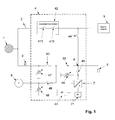
- Fig.1 shows an embodiment of an additional device according to the invention 4. This comprises connections for a first counter 2, which is designed as in particular as a feed-in counter and a second counter 3, which is designed in particular as a reference counter.
- the additional device 4 is connected by the feed meter 2 and the reference counter 3.
- one or more own generating plant 5 for example, solar generator with solar inverter
- the consumer 6 and optionally also a generator 8 are connected.
- the island inverter can consist of one or more parallel-connected island inverters.
- the network monitoring (ENS) that may be present in the in-house generating plant will be shut down as soon as the connection of the own generating plant 5 to the auxiliary device 4 has taken place.
- the island inverter 7 is on its DC side with an energy storage, eg. B. a battery 71, connected.
- the island inverter 7 may have an internal galvanic isolation between AC and DC side. This separation can be realized via a transformer which is operated at line frequency or via one or more high-frequency transformers.
- the island inverter 7 is advantageously designed as an H-bridge of semiconductor switches. These semiconductor switches may consist of MOS transistors, IGBT transistors or GTO thyristors.
- the island inverter 7 is inventively designed such that in case of a short circuit in load circuits during island operation existing overcurrent protection devices of the load circuits are triggered.
- the contactor 45 is controlled such that in the event of a short circuit in a load circuit and associated breakdown of the voltage at node 9, the contactor contacts remain closed until the short-circuit current of the island inverter 7, the associated overcurrent protective device of the load circuit triggers and thus the voltage in the node 9 is restored.
- the additional device 4 contains an interface unit 41. This unit is used to link the island inverter or inverters 7 with the sensors and actuators in the auxiliary device 4.
- a suitable data bus for example CAN bus
- the one or more self-generation plants are connected via the automatic separation point 42 to the feed-in counter 2.
- This separation point contains at least one contactor 411; but it may have another contactor 412 in series with this contactor.
- the contactors 411 and 412 can be designed as one-pole or all-pole.
- the consumers 6 are connected via the transfer contactor 43 to the network 1.
- the contactor 44 connects the self-generating system 5 via the node 9 with the consumers 6 when the transfer gate 43 is opened and the system runs in island mode.
- the contactor 45 connects the island inverter 7 via the node 9 with the consumers 6.
- the contactor 46 connects a generator 8 via the node 9 with the consumers 6.
- the additional device 4 contains at least the following measured value captures: mains voltage measurement 47, AC voltage measurement stand-alone inverter 49, AC current measurement 50.
- a generator voltage measurement 48 may be present.
- the contactors 411, 412, 43 and 45 are closed, the contactors 44 and 46 are open.
- the consumers 6 are supplied from the network 1 via the reference counter 3 with energy.
- the self-generation plants 5 feed energy into the public network 1 via the feed-in counter 2.
- the island inverter 7 charges the energy storage 71. In this case, only a trickle charge with low energy consumption is usually required when the energy store is charged.
- the stand-alone inverter 7 With the aid of measured values for line voltage and line current and a suitable anti-islanding method, the stand-alone inverter 7 constantly monitors the network parameters of the supply network and can thus reliably detect whether an island network is present or not.
- the island inverter 7 operates voltage-controlled.
- the internal bridge voltage in the stand-alone inverter 7 is controlled such that it is adjusted in magnitude and phase with respect to the voltage at the node so that the voltage at the node results as desired and a predetermined battery charging current is set.
- the stand-alone inverter If a defect or a temporary error condition occurs in the stand-alone inverter, it can be disconnected via the contactor 45 from the connection point 9. If the error condition is eliminated, it can synchronize itself again with the aid of the voltage measurements 47 and 49 to the voltage at the connection point 9 and resume the charging operation of the energy store 71.
- the stand-alone inverter 7 If the network 1 is switched off, there is a short circuit in the vicinity, or the power supply in the public grid collapses, this is detected by the stand-alone inverter 7.
- the island inverter now tries to keep the voltage at the node 9 stable via its voltage regulation.
- the contactors 411, 412 and 43 are opened. If by the conditions during the Transition state of the current from the island inverter 7 exceeds a certain maximum, the island inverter 7 limits this current to this maximum value, so that the internal components of the island inverter are not overloaded.
- the voltage at the node 9 then drops accordingly. As soon as the above-mentioned contactors are opened, the current only flows into the consumers 6. The voltage at the connection point 9 again reaches its nominal value.
- the contactor 44 is closed, so that the self-generating system can automatically synchronize to the island grid at node 9. Now the developed island grid can continue to be operated as long as the self-generation system provides enough energy on average. Variations in production and consumption are compensated by the island inverter 7 and its energy storage 71.
- an existing generator 8 (e.g., a diesel generator) may be connected via a contactor 46.
- the island inverter synchronizes with the aid of the generator voltage measurement 48 and the voltage measurement 49, the voltage in the node 9 to the output voltage of the generator 8. After synchronization, the generator contactor 46 is closed.
- the contactor 44 is first opened.
- the self-generation system switches then off.
- the voltage at the node 9 is synchronized with the voltage in the network 1 and the transfer contactor 43 is closed.
- the contactors 411 and 412 are closed, so that the self-generating system 5 can again go into operation via the feed meter 2 on the grid.
- the consumers 6 are supplied from the network and the self-generating system 5 feeds into the network 1.
- the transfer contactor 43 can be designed as an opener or consist of semiconductor switches. It can be controlled so that it is always closed in the event that the auxiliary device is defective when mains voltage is applied. This can ensure that the consumers are not disconnected from the mains if there is a defect in the ancillary equipment.
- All components of the additional device 4 can be arranged in a suitable box, in one or more control cabinets in the in-house generating plant 5 or in the island inverter 7.
- the island inverter 7 and the energy storage 71 are part of the additional device. 4
- the consumers 6 can be completely supplied by the own generating plant 5, as long as the power generation is greater than or equal to the consumption. With the energy storage only the differential energy between generation and consumption needs to be exchanged. This increases the efficiency of the overall system as an advantage of the AC coupling.
- the self-generation plant is preferably a PV system with an associated PV inverter. Furthermore, it can be a variable-speed wind energy plant with a PM generator (permanent synchronous generator).
- Fig.2 shows the formation of the system, wherein the transfer contactor 43 is formed so that when switching from mains parallel operation for island operation, the pole of the contactor, which is connected to the neutral of the node 9 is switched from the neutral conductor of the network to PE.
- Fig. 3 shows the formation of the system with several (n) island inverters and several (m) self-generating plants on one phase.
- the island inverters can be linked with each other and with the interface unit 41 via a suitable data bus connection.
- Fig. 4 shows the formation of the system, in a three-phase connection to the public power grid and an island inverter per phase.
- Fig. 5 shows the formation of the system, in a three-phase connection to the public power grid and a three-phase stand-alone inverter.
- Fig. 6 shows the formation of the system, wherein the three-phase transfer contactor 43 is designed so that when switching from mains parallel operation to isolated operation, the pole of the contactor, which is connected to the neutral of the node 9, can be switched from the neutral of the network to PE.
- the switching can also be realized by multiple contactors.
- Fig. 7 shows the formation of the system in a three-phase connection to the public power grid and more than one island inverters per phase. At each phase are 0 to m
- Own generation plants connected. It is also possible to connect 0 to m three-phase self-generation plants.
- Fig. 8 shows the formation of the system in a three-phase connection to the public power grid and more than a three-phase island inverter. 0 to m self-generation plants are connected to each phase. It is also possible to connect 0 to m three-phase self-generation plants.
- the self-generation plants can be designed with different modes for island operation and grid parallel operation.
- a switchover between the modes can take place.
- a further improved stability in off-grid operation can be achieved.
- the switching is designed so that in case of failure or disruption of the data connection between the own generating plant and the additional device, the own generation plant switches to the operating mode "grid parallel operation" or remains in this.
- the additional device can receive data from the responsible grid operator. If appropriate arrangements exist with the utility operator, the ancillary equipment can use this data to exchange reactive and / or real power with the public grid to stabilize the voltage at the tie point. As a result, z. B. caused by the feed of the power generation plant overvoltages or caused by large consumers undervoltages are avoided at the point of connection.
- All switching elements can be designed both as contactors and as relays or printed circuit board equipped relays.
- the self-generating system may consist of a wind turbine with a synchronous generator, PM generator or an asynchronous generator and an inverter, a wind turbine with a grid-connected synchronous or asynchronous generator, a fuel cell with an associated inverter.
- the self-generation plant can be a hydroelectric power station with a grid-connected synchronous or asynchronous generator or a variable-speed hydropower plant with a PM generator, a synchronous generator or an asynchronous generator and an associated grid inverter.
- the self-generating system of an internal combustion engine with a grid-connected synchronous or asynchronous generator, a variable-speed combustion engine with a PM generator, a synchronous generator or an asynchronous generator and associated network inverter consist.
- the self-generating system may consist of a fuel cell with an associated inverter or be a different type of self-generating system.
- the backup power system is operated in parallel to the own generation plant, to the consumers and public utility networks, so that a modular expandability and a problem-free addition of existing facilities is possible.
- Existing self-generation plants can be modularly expandable to replacement power supplies.
- the power of the backup power supply can be subsequently increased in a simple manner.
- An AC-side parallel connection of self-generation plant, public power grid, consumers and backup power supply can be given.
- the supply of the consumer can not be interrupted for more than 30 ms.
- the extra power needed to provide an uninterruptible power supply can be minimal.
- the energy fed into the public power grid by the in-house power generation plant can not be reduced by the additional equipment.
Abstract
Description
Die Erfindung betrifft eine Zusatzeinrichtung, die zwischen einem öffentlichen Energienetz und einer Energieversorgungsanlage anschließbar ist.The invention relates to an additional device which can be connected between a public power grid and a power supply system.
Es sind Eigenerzeugungsanlagen für elektrische Energie wie Solargeneratoren, Windenergieanlagen mit PM-Generator, drehzahlvariable Verbrennungsmotoren oder Brennstoffzellen, deren in ein Netz eingespeiste Leistung stark variiert, bekannt. Für solche Eigenerzeugungsanlagen gelten häufig attraktive Sondertarife, so dass es für den Betreiber solcher Anlagen wirtschaftlich immer lohnender wird, den erzeugten Strom ins öffentliche Versorgungsnetz einzuspeisen. Die Abrechnung von erzeugter und verbrauchter Energie erfolgt aufgrund der unterschiedlichen Tarife in der Regel durch unterschiedliche Zähler. Beim Parallelbetrieb mit dem öffentlichen Netz müssen hierbei besondere Sicherheits- und Anschlussbedingungen berücksichtigt werden.These are self-generating systems for electrical energy such as solar generators, wind turbines with PM generator, Variable speed internal combustion engines or fuel cells whose power fed into a grid varies widely known. For such own generation plants often apply attractive special tariffs, so that it becomes economically more profitable for the operator of such systems to feed the electricity generated in the public grid. The billing of generated and used energy is due to the different rates usually by different counters. For parallel operation with the public network, special safety and connection conditions must be taken into account.
Bekannt ist auch die sogenannte Netzüberwachung, die von hoher Bedeutung ist. Eine Eigenerzeugungsanlage muss nämlich erkennen, wenn das öffentliche Netz ausfällt, und dann ihren Betrieb einstellen. Sie darf dann nicht weiter ins das Netz einspeisen, weil eventuell bei Wartungsarbeiten im öffentlichen Netz eine Personengefährdung eintreten kann, wenn ein Netzabschnitt freigeschaltet wurde und die Eigenerzeugungsanlage in diesem Abschnitt dennoch weiter arbeitet. Bekannt sind Netzüberwachungsverfahren, die in passive und aktive Verfahren unterteilt werden. Passive Verfahren werten nur die Messwerte von einphasiger und dreiphasiger Netzspannung und Netzfrequenz aus. Aktive Verfahren zeichnen sich dadurch aus, dass sie durch Strom- oder Spannungsverzerrungen das Netz derart beeinflussen, dass aus der Antwort auf die Netzparameter bzw. die Netzimpedanz geschlossen werden kann. Durch eine Stromverzerrung erhält man eine Spannungsantwort und umgekehrt durch eine Spannungsverzerrung eine Stromantwort.Also known is the so-called network monitoring, which is of great importance. In fact, a self-generating installation must detect when the public grid fails and then stop operating. It may then no longer feed into the grid, because there may be a risk of personal injury during maintenance work in the public network, if a network section has been unlocked and the self-generating system continues to work in this section. Network monitoring methods are known which are subdivided into passive and active methods. Passive methods only evaluate the measured values of single-phase and three-phase mains voltage and mains frequency. Active methods are characterized by the fact that they influence the network by means of current or voltage distortions in such a way that it is possible to conclude from the response to the network parameters or the network impedance. By means of a current distortion one obtains a voltage response and vice versa by a voltage distortion a current response.
Im sogenannten Netzbetrieb muss somit eine Netzüberwachung wirksam sein. Im sogenannten Inselnetzbetrieb, bei der die Verbindung zum öffentlichen Netz unterbrochen ist und nur die Verbraucher eines definierten vorbekannten Abschnitts weiter versorgt werden, ist es bekannt, die Netzüberwachung abzuschalten. Dies erfolgt, weil die Netzimpedanz während des Netzbetriebs deutlich geringer ist als die Impedanz im Inselnetzbetrieb. Zudem wird bei einem solchen Vorgehen die modulare Erweiterbarkeit erleichtert, da sich bei einer modularen Erweiterung die Netzimpedanz des Inselnetzes verändert. Fehlabschaltungen, insbesondere bei größeren Lastsprüngen, der internen Netzüberwachung der Eigenerzeugungsanlage, die auf die veränderten Netzparameter zurückzuführen wären, werden in vorteilhafter Weise vermieden. Das gesamte System wird dadurch stabiler, insbesondere wenn es als Inselnetz betrieben wird.In so-called network operation, network monitoring must therefore be effective. In the so-called off-grid operation, in which the connection to the public network is interrupted and only the consumers of a defined known section continue to be supplied, it is known to turn off the network monitoring. This occurs because the network impedance during mains operation is significantly lower than the impedance in off-grid operation. In addition, the modular expandability is facilitated in such an approach, since the network impedance of the island grid changes in a modular extension. False shutdowns, especially in the case of larger load jumps, of the internal network monitoring of the self-generation plant, which would be due to the changed network parameters, are avoided in an advantageous manner. The entire system is thus more stable, especially if it is operated as a stand-alone grid.
Bekannt sind Eigenerzeugungsanlagen, bei der die elektrischen Verbraucher weiter versorgt werden, wenn das öffentliche Energieversorgungsnetz ausfällt. Hierzu sind Zusatzeinrichtungen erforderlich.Self-generating systems are known in which the electrical consumers are still supplied when the public power grid fails. For this purpose, additional equipment is required.
Eine Zusatzeinrichtung in diesem Sinne ist eine Funktionseinheit, die der Betreiber installieren muss, um eine vorhandene Eigenerzeugungsanlage als Ersatzstromversorgung zu ertüchtigen.An additional device in this sense is a functional unit that the operator must install in order to make an existing self-generation system suitable for replacement power supply.
In vorteilhafter Weise ist bei einem Anstieg der elektrischen Verbraucher, die mit einer Ersatzstromversorgung versorgt werden sollen, das System nur durch Hinzufügen weiterer Komponenten modular erweiterbar, ohne dass bestimmte elektrische Verbraucher einer bestimmten Funktionseinheit der Zusatzeinrichtung zugeordnet sein müssen.Advantageously, in the case of an increase in the electrical consumers which are to be supplied with an alternative power supply, the system can be modularly expanded only by adding further components without having to associate certain electrical consumers with a specific functional unit of the additional device.
Damit eine unterbrechungsfreie Versorgung der Verbraucher gewährleistet werden kann, ist es zweckmäßig, die Ersatzstromanlage so zu betreiben, dass sie in einem Ladebetrieb, bei dem ein öffentliches Netz vorhanden ist, und im Endladebetrieb, bei dem ein öffentliches Netz nicht vorhanden ist, immer im gleichen Regelmodus betrieben wird, so dass keine Unterbrechung zur Reglerumschaltung notwendig ist. Das gleiche gilt für den Fall, dass das öffentliche Energieversorgungsnetz wiederkehrt.In order to ensure an uninterrupted supply to consumers, it is appropriate to operate the backup system in such a way that it is always in the same mode in a charging operation where a public network is present and in a final charging operation where a public network does not exist Control mode is operated, so no Interruption is necessary for controller switching. The same applies in the event that the public power grid returns.
Wenn Eigenerzeugungsanlagen an Netzausläufern installiert werden, können sich bei hoher Einspeisung und kleinem Verbrauch in diesem Netzausläufer unzulässig hohe Netzspannungen ergeben. Die Zusatzeinrichtung kann nun dazu genutzt werden, in solchen Momenten Energie aufzunehmen und die Netzspannung entsprechend abzusenken. Dadurch kann das Netz so stabilisiert werden, dass auch bei Netzausläufern, Eigenerzeugungsanlagen installiert werden können, was ansonsten nicht möglich wäre.If self-generation systems are installed on network feeders, high supply voltages and low consumption can result in excessively high grid voltages in this grid outlet. The additional device can now be used to absorb energy in such moments and to lower the mains voltage accordingly. As a result, the network can be stabilized in such a way that self-generating systems can also be installed in the case of network outlets, which would otherwise not be possible.
Auf der anderen Seite kann an diesen Netzausläufern bei einem sehr hohen Verbrauch, die Netzspannung unzulässig niedrige Werte erreichen. Die Zusatzeinrichtung kann auch hier genutzt werden, um die hohen Verbrauchsspitzen aus der Batterie zu decken. Die Netzspannung am Verbrauchsknoten kann somit auch bei größeren elektrischen Verbrauchern noch stabil gehalten werden.On the other hand, with very high power consumption, the line voltage can reach inadmissibly low values at these mains outlets. The additional device can also be used here to cover the high consumption peaks from the battery. The mains voltage at the consumption node can thus be kept stable even with larger electrical loads.
Bekannt sind netzparallele Eigenerzeugungsanlagen, die zusätzlich als Ersatzstromversorgungen nutzbar sind.Network-parallel self-generation systems are known, which are additionally usable as backup power supplies.
Aus der
Dieses System wird derart betrieben, dass eine Ersatzstromversorgung dadurch erfolgt, dass im Falle eines Ausfalls des öffentlichen Energieversorgungsnetzes die Eigenerzeugungsanlage vom Netz getrennt wird. Eine zusätzliche Steckdose wird dann mit elektrischer Energie versorgt. Ein Wechselrichter, der die Spannung an dieser Steckdose zur Verfügung stellt, wird dann durch eine Batterie versorgt. Die Batterie wird von einem Batterieladegerät geladen, das entweder aus dem öffentlichen Energieversorgungsnetz oder von den Eigenerzeugungsanlagen versorgt wird.This system is operated in such a way that an alternative power supply takes place in that in the event of a failure of the public power grid, the own generating plant is disconnected from the grid. An additional socket is then supplied with electrical energy. An inverter that controls the voltage at this outlet Is then powered by a battery. The battery is charged by a battery charger, which is supplied either from the public power grid or from the self-generating facilities.
Die hierfür ausgebildeten Eigenerzeugungsanlagen sind so ausgeführt, dass sie nach einem Umschaltvorgang auch im Inselnetz weiterbetrieben werden können. An dieses Inselnetz ist nur das Batterieladegerät angeschlossen.The purpose designed self-generating systems are designed so that they can continue to operate after a switching operation in the island grid. Only the battery charger is connected to this island grid.
Im Falle eines Ausfalls des öffentlichen Netzes müssen manuell elektrische Verbraucher an die zusätzliche Steckdose angeschlossen werden, was einerseits unkomfortabel ist und andererseits wegen der Stromunterbrechung in einigen Fällen höchst unerwünscht ist.In case of failure of the public network, electrical loads must be manually connected to the additional socket, which is on the one hand uncomfortable and on the other hand, because of the power interruption in some cases is highly undesirable.
Wenn elektrische Verbraucher immer über die zusätzliche Steckdose versorgt werden, müssen Verluste, die im Batterieladegerät und im zusätzlichen Wechselrichter entstehen, im Kauf genommen werden. In diesem Fall wird die Anlage als sogenannte Online USV Anlage betrieben. Falls die Online USV Anlage defekt ist, müssen die elektrischen Verbraucher, die über die Anlage versorgt wurden über eine zusätzliche Umschalteinrichtung mit dem öffentlichen Energieversorgungsnetz verbunden werden.If electrical loads are always supplied via the additional socket, losses incurred in the battery charger and in the additional inverter must be taken into account. In this case, the system is operated as a so-called online UPS system. If the online UPS system is defective, the electrical consumers supplied via the system must be connected to the public power supply network via an additional switchover device.
Eine gesicherte Stromversorgung ist bei dieser Lösung für die zugeordneten Verbraucher gegeben.A secure power supply is given in this solution for the associated consumers.
Diese USV-Anlage hat zudem weitere Nachteile. Wenn die Anlage als Online USV-Anlage betrieben wird, müssen zusätzliche Wandlungsverluste in Kauf genommen werden, eine Datenverbindung zwischen der vorhandenen Eigenerzeugungsanlagen und der Umschalteinheit ist des Weiteren erforderlich. Dadurch ist eine Erweiterung einer vorhandenen Eigenerzeugungseinheit zu einer Anlage mit gesicherter Stromversorgung erschwert, da dann, wenn die Online USV-Anlage defekt ist, die elektrischen Verbraucher, die über diese Anlage versorgt wurden, über eine zusätzliche Umschalteinrichtung mit dem öffentlichen Energieversorgungsnetz verbunden werden müssen. Elektrische Verbraucher mit gesicherter Versorgung sind genau einem Batteriewechselrichter zugeordnet. Dadurch können sehr große Verbraucher nicht mehreren Wechselrichtern zugeordnet werden. Eine Vielzahl von Verbrauchern muss außerdem immer auf bestimmte Wechselrichter aufgeteilt werden.This UPS system also has other disadvantages. If the system is operated as an online UPS system, additional conversion losses must be accepted, a data connection between the existing own generation facilities and the switching unit is the Further required. As a result, an extension of an existing self-generating unit to a system with a secured power supply is difficult because then, if the online UPS system is defective, the electrical consumers who were supplied via this system must be connected via an additional switching device to the public power grid. Electric consumers with a secured supply are assigned to exactly one battery inverter. As a result, very large consumers can not be assigned to multiple inverters. In addition, a large number of consumers must always be distributed to specific inverters.
Darüber hinaus sind die Eigenerzeugungsanlage, elektrische Verbraucher und Ersatzstromversorgung nicht AC-seitig parallel geschaltet, so dass also eine gesicherte Stromversorgung und Parallelbetrieb zum öffentlichen Energieversorgungsnetz nicht möglich ist.In addition, the self-generating system, electrical consumers and backup power supply are not connected in parallel on the AC side, so that a secure power supply and parallel operation to the public power grid is not possible.
In der
Bei dieser Einrichtung ist nur ein DC/AC-Konverter für die Einspeisung von elektrischer Energie in das öffentliche Energieversorgungsnetz oder für die Versorgung spezieller elektrischer Verbraucher für den Fall eines Netzausfalls vorgesehen.In this device, only a DC / AC converter for the supply of electrical energy in the public power grid or for the supply of special electrical loads in the event of a power failure is provided.
Weil die Energiequelle, beispielsweise ein Photovoltaikgenerator, in den hier beschriebenen Fällen eine stark schwankende Spannung aufweist, muss ein bidirektionaler Anpasssteller zwischen der Energiequelle und der Batterie vorgesehen sein.Because the power source, such as a photovoltaic generator, has a widely varying voltage in the cases described herein, a bidirectional matching actuator must be provided between the power source and the battery.
Dem DC/AC Konverter ist eine sogenannte "Transfer Unit" nachgeschaltet. Im Falle eines Netzausfalls trennt diese Einheit den DC/AC Konverter und die speziellen Verbraucher vom Netz. Danach werden sie mit dem Ausgang des DC/AC Konverters verbunden und von diesem versorgt. Während der Umschaltzeit werden die Verbraucher nicht versorgt.The DC / AC converter is followed by a so-called "transfer unit". In case of power failure, this unit disconnects the DC / AC converter and the special loads from the mains. Then they are connected to the output of the DC / AC converter and supplied by this. During the switching time, the consumers are not supplied.
Alternativ zu der Versorgung aus dem Photovoltaik-Generator kann jedoch die Batterie über ein separates Batterieladegerät aus dem öffentlichen Energieversorgungsnetz geladen werden.As an alternative to the supply from the photovoltaic generator, however, the battery can be charged via a separate battery charger from the public power grid.
Bei dieser Offline Lösung ist, außer dass elektrische Verbraucher nicht ohne Unterbrechung versorgt werden können, eine modulare Erweiterbarkeit nicht gegeben, da eine bestimmte Anzahl von speziellen Verbrauchern einem bestimmten DC/AC Konverter zugeordnet sind. Dadurch können Verbraucher großer Leistung nicht mehreren DC/AC Konvertern zugeordnet werden. Eine Vielzahl von Verbrauchern muss daher immer auf bestimmte DC/AC Konverter aufgeteilt werden. Ein weiterer Nachteil ist, dass die gesamte Anlage schon bei der Erstinstallation der Eigenerzeugungsanlage für einen Betrieb als gesicherte Stromversorgung ausgelegt sein muss, da die Batterie auf der DC-Seite angebunden sein muss und der DC/AC Konverter von vorne herein auch für den Inselbetrieb geeignet sein muss. Zudem können vorhandene Eigenerzeugungsanlagen ohne DC Zwischenkreis, insbesondere Windgeneratoren mit Asynchrongenerator, nicht eingebunden werden.In this off-line solution, except that electrical loads can not be powered on uninterrupted, modular expandability is not given because a certain number of special loads are associated with a particular DC / AC converter. As a result, high power consumers can not be assigned to multiple DC / AC converters. A large number of consumers must therefore always be divided between specific DC / AC converters. Another disadvantage is that the entire system must be designed for operation as a secure power supply already at the initial installation of the own generation plant, since the battery must be connected on the DC side and the DC / AC converter from the outset also suitable for island operation have to be. In addition, existing self-generation plants without DC intermediate circuit, in particular wind generators with asynchronous generator, can not be integrated.
Eine zusätzliche Einrichtung, nämlich ein bidirektionaler Anpasssteller, ist erforderlich und verteuert die Anlage.An additional device, namely a bidirectional adapter plate, is required and makes the system more expensive.
Wenn die Batterie auch aus dem öffentlichen Energieversorgungsnetz geladen werden soll, ist darüber hinaus ein zusätzliches Batterieversorgungsgerät erforderlich.In addition, if the battery is to be charged from the public power grid, an additional battery backup device is required.
Bekannt sind auch Lösungen mit einer Kopplung von einem Batteriewechselrichter und einer Eigenerzeugungsanlage auf der AC Seite.Also known are solutions with a coupling of a battery inverter and a self-generating system on the AC side.
Im Katalog "Smarte Energiekonzepte", August 2006, der Fa. Studer in Sion (Schweiz) wird auf der Seite 11 ein System beschrieben, bei dem ein Batteriewechselrichter mit einer Eigenerzeugungsanlage kombiniert wird, wobei die Netzüberwachung der Eigenerzeugungsanlage im Netzbetrieb und im Inselbetrieb in Funktion bleibt.In the catalog "Smart Energy Concepts", August 2006, the company Studer in Sion (Switzerland) is described on page 11, a system in which a battery inverter is combined with a self-generation plant, the grid monitoring of the own generation plant in grid operation and island operation in function remains.
Ein solches System wird derart geregelt, dass im Ladebetrieb eine Stromregelung im Inselwechselrichter wirksam ist. Wenn ein Netzausfall stattfindet, muss die Regelung auf eine Spannungsregelung umgeschaltet werden. Dadurch entsteht bei allen Netzkonfigurationen eine Unterbrechung bei der Versorgung der Verbraucher.Such a system is regulated in such a way that a current regulation in the stand-alone inverter is effective in the charging mode. If a power failure occurs, the control must be switched to voltage regulation. This creates an interruption in the supply of consumers in all network configurations.
Ein Nachteil dieses Systems besteht darin, dass die Eigenerzeugungsanlage im Inselbetrieb häufig abschaltet, weil die Netzparameter sich beim Zu- und Abschalten von Verbrauchern im Inselbetrieb stärker ändern als im Netzbetrieb. Dadurch ist die Stabilität des gesamten Systems eingeschränkt. Weiter wird eine modulare Erweiterbarkeit erschwert. Bei einer Kopplung von Batteriewechselrichter und Eigenerzeugungsanlage auf der AC Seite entsprechend dem Stand der Technik, kann eine unterbrechungsfreie Versorgung der Verbraucher nicht erreicht werden, weil eine Reglerumschaltung notwendig ist.A disadvantage of this system is that the self-generating system often shuts off island operation, because the network parameters change more when switching on and off of consumers in island operation as in network operation. This limits the stability of the entire system. Furthermore, modular expandability is made more difficult. In a coupling of battery inverter and self-generating system on the AC side according to the prior art, an uninterruptible supply to the consumer can not be achieved because a regulator switching is necessary.
Der hier beschriebenen Erfindung liegt die Aufgabe zugrunde, eine gegenüber dem Stand der Technik verbesserte Lösung zur Erweiterung von netzparallelen Eigenerzeugungsanlagen auf der Netzseite zu finden, bei der eine Eigenerzeugungsanlage derart ergänzt wird, dass sie einerseits zusätzlich als Ersatzstromversorgung nutzbar und andererseits modular erweiterbar ist.The invention described herein is based on the object of finding a solution, which is improved over the prior art, for expanding network-parallel self-generating systems on the network side, in which a self-generating system is supplemented in such a way that it on the one hand additionally usable as a spare power supply and on the other hand modular expandable.
Diese Aufgabe wird durch eine Zusatzeinrichtung gelöst, die zwischen einem öffentlichen Energieversorgungsnetz und einer Eigenerzeugungsanlage anschließbar ist, wobei die Eigenerzeugungsanlage einerseits eine mittels einer selbsttätigen Freischaltstelle mit mindestens einem ersten Schalter parallel zum öffentlichen Energieversorgungsnetz zuschaltbare AC-Spannung zur Einspeisung in das öffentliche Energiestromnetz liefert, wobei eine in der Zusatzeinrichtung befindliche Netzüberwachungseinrichtung zum Öffnen des ersten Schalters bei Netzausfall des öffentlichen Energiestromnetzes vorhanden ist und die Eigenerzeugungsanlage andererseits unmittelbar über ein zweites Schaltelement mit einem oder mehreren an die Zuatzeinrichtung anschließbaren elektrischen Verbraucher zuschaltbar ist sowie einem Schalter, der den Verknüpfungspunkt, an dem der Inselwechselrichter mit seinem Speicher, die Verbraucher sowie das zweite Schaltelement angeschlossen sind, mit dem öffentlichen Energiestromnetz verbindet.This object is achieved by an additional device which can be connected between a public power grid and a self-generating system, the self-generating system on the one hand provides an automatically connected by means of an automatic disconnection point with at least a first switch switchable parallel to the public power grid AC voltage for feeding into the public power grid a power monitoring device located in the additional device for opening the first switch in the event of power failure of the public power grid is on the other hand, the self-generating system on the other hand directly via a second switching element with one or more connectable to the Zuatzeinrichtung electrical consumers can be switched on and a switch, the link point at which the Island inverter with its memory, the consumer and the second switching element are connected to the public power tromnet connects.
Durch die Erfindung wird eine Zusatzeinrichtung zur Erweiterung von netzparallelen Eigenerzeugungsanlagen zur Ersatzstromversorgung geschaffen.The invention provides an additional device for the expansion of network-parallel self-generating systems for replacement power supply.
Die Erfindung kann zusätzlich zu einer bestehenden Eigenerzeugungsanlage installiert werden, ohne dass die vorhandene Einspeiseeinrichtung (z.B. Solarwechselrichter) ersetzt werden muss.The invention may be installed in addition to an existing in-house generation plant without having to replace the existing feed facility (e.g., solar inverter).
Die Erfindung erlaubt außerdem den Parallelbetrieb einer z.B. batteriegestützten Ersatzstromversorgung zum öffentlichen Energieversorgungsnetz (andere Energiespeicher wie Schwungradspeicher, UC Kondensatoren, EEStore, Brennstoffzelle usw. sind auch möglich) und verwirklicht folgende Vorteile:The invention also allows the parallel operation of a battery-powered backup power supply to the public power grid (other energy storage such as flywheel storage, UC capacitors, EES gates, fuel cell, etc. are also possible) and realizes the following advantages:
Ein Energiespeicher einer Ersatzstromanlage kann ständig nachgeladen werden, so dass bei Netzausfällen genügend Energie zur Verfügung steht. Dabei kann der Energiefluss und die Spannung des Energiespeichers so beeinflusst werden, dass eine lange Lebensdauer des Speichers gewährleistet wird.An energy storage of a backup power system can be recharged constantly, so that in case of power outages enough energy is available. In this case, the energy flow and the voltage of the energy storage can be influenced so that a long life of the memory is guaranteed.
Für die Eigenerzeugungsanlagen wird eine "selbsttätige Freischaltstelle" (früher ENS) zur Verfügung gestellt, damit eine interne selbsttätige Freischaltstelle der Eigenerzeugungsanlage außer Betrieb genommen werden kann. Somit kann die Eigenerzeugungsanlage vorteilhaft auch im Inselbetrieb weiter genutzt werden.A self-service release point (formerly ENS) will be provided for the self-generation facilities, so that an internal self-service disconnection point of the in-house generation plant can be taken out of service. Thus, the self-generating system can be advantageously used in island operation.
Im Falle eines Ausfalls des öffentlichen Versorgungsnetzes können die Verbraucher in der Regel ohne Unterbrechung mit Energie versorgt werden. Bei Unterbrechung zum Energieversorgungsnetz wird dann ein Inselnetz gebildet, solange bis das Energieversorgungsnetz wieder funktionstüchtig ist. Dann können die Verbraucher wieder aus dem öffentlichen Energieversorgungsnetz versorgt werden.In the event of a failure of the public supply network, consumers can generally be supplied with energy without interruption. In the event of an interruption to the energy supply network, a stand-alone network is then formed until the power supply network is operational again. Then the consumers can be supplied again from the public power grid.
Vor dem Wiederzuschalten kann das Inselnetz in Spannung und Frequenz mit dem öffentlichen Energieversorgungsnetz synchronisiert werden.Before reconnecting, the island grid can be synchronized in voltage and frequency with the public power grid.
Im Falle von Kurzschlüssen im öffentlichen Energieversorgungsnetz kann der Spannungseinbruch an den Verbrauchern, die von der Ersatzstromversorgung versorgt werden, nicht länger als 30 ms andauern.In the event of short circuits in the public power grid, the voltage drop on the loads supplied by the backup power supply can not last longer than 30 ms.
Aller Sicherheitsanforderungen bei der Einspeisung entsprechend den gültigen Regeln der Technik werden erfüllt.All safety requirements for the supply according to the valid rules of technology are fulfilled.
Es ist außerdem möglich, den Energiebezug aus dem öffentlichen Energieversorgungsnetz und die Einspeisung der Eigenerzeugungsanlage über getrennte Zähler abzurechnen.It is also possible to settle the energy supply from the public power grid and the infeed of the own generation plant via separate meters.
In einer weiteren vorteilhaften Weiterbildung der erfindungsgemäßen Zusatzeinrichtung ist vorgesehen, dass eine Inselnetzerkennungseinrichtung vorhanden ist, die derart ausgeführt ist, dass sie die Kupplung der Eigenerzeugungsanlage mit dem Energiestromnetz steuert, so dass bei Ausfall des Energiestromnetzes die Zusatzeinrichtung vollständig vom Energiestromnetz getrennt werden kann. Hierdurch kann der Energiebedarf von elektrischen Verbrauchern bei geringer Energielieferung durch die Eigenerzeugungsanlage gedeckt werden und zwar durch den Energiespeicher, zum Beispiel eine Batterie, die am Inselwechselrichter angeschlossen ist. Dies ist bei Einsatz von Photovoltaikgeneratoren in der Eigenerzeugungsanlage wichtig, da diese Nachts keine Energie liefern oder bei geringer Sonnenstrahlung zu wenig Energie liefern.In a further advantageous development of the additional device according to the invention it is provided that an island network detection device is provided which is designed such that it controls the coupling of the self-generating system with the power grid, so that in case of failure of the power grid, the additional device can be completely separated from the power grid. As a result, the energy requirement of electrical consumers can be covered by the in-house generation system with a low energy supply and by the energy storage, for example, a battery that is connected to the island inverter. This is important when using photovoltaic generators in the in-house generation plant, as they do not provide energy at night or provide too little energy in low solar radiation.
Ein optimale Anpassung an einen steigenden Strombedarf ist gegeben, wenn mehrere Eigenerzeugungsanlagen parallel angeschlossen sind. Da die Zusatzeinrichtung zwischen dem öffentlichen Energiestromnetz und der Eigenerzeugungsanlage einen Schalter umfasst, der als Schütz ausgeführt sein kann, und der Schalter auch relativ kostengünstig für hohe Stromstärken ausgelegt sein kann ist eine modulare Erweiterung möglich. Liefert die Eigenerzeugungsanlage zu wenig Energie, zum Beispiel nachts bei Solargeneratoren, sind zweckmäßigerweise mehrere Inselwechselrichter parallel geschaltet.An optimal adaptation to an increasing power requirement is given if several own generation plants are connected in parallel. Since the additional device between the public power grid and the self-generation system includes a switch that can be designed as a contactor, and the switch can also be designed relatively inexpensive for high currents a modular extension is possible. If the in-house generation plant supplies too little energy, for example at night in the case of solar generators, it is expedient to connect several island inverters in parallel.
In einer weiteren vorteilhaften Ausführung der Erfindung wird die Zusatzeinrichtung wie eine Online-USV-Anlage eingesetzt, wobei es günstig ist, wenn die Schaltzeit jedes Schalters höchstens 50 ms, insbesondere höchstens 30 ms beträgt, wobei jeder Schalter als Schütz ausgeführt ist. Dadurch ist eine sichere unterbrechungsfreie Stromversorgung gegeben.In a further advantageous embodiment of the invention, the additional device is used like an online UPS system, wherein it is favorable if the switching time of each switch is at most 50 ms, In particular, at most 30 ms, each switch is designed as a contactor. This provides a secure uninterruptible power supply.
Vorteilhaft ist weiterhin, wenn die Zusatzeinrichtung eine selbsttätige Freischaltstelle enthält, wodurch die Netzüberwachung der Eigenerzeugungsanlage so eingestellt werden kann, dass sie sowohl im Netzparallelbetrieb als auch im Inselbetrieb betrieben werden kann, was bedeutet, dass die Netzüberwachung von der Zuatzeinrichtung mit den Inselwechselrichtern übernommen wird.It is also advantageous if the additional device includes an automatic release point, whereby the grid monitoring of the own generation plant can be set so that they can be operated both in grid parallel operation and island operation, which means that the grid monitoring is taken over by the additional device with the island inverters.
Weiterhin weist die Zusatzeinrichtung eine selbsttätige Freischaltstelle, einen Transferschütz, einen Schütz, eine Netzspannungsmessung und eine Netzstrommessung auf, wodurch die Einrichtung autark betrieben werden kann.Furthermore, the additional device has an automatic release point, a transfer contactor, a contactor, a mains voltage measurement and a mains current measurement, whereby the device can be operated independently.
Bei Einsatz als mobile Anlage ist vorteilhaft vorgesehen, dass der Transferschütz ein zweipoliges Schütz ist, wobei der eine Pol so ausgebildet ist, dass bei Wechsel vom Netzparallelbetrieb zum Inselbetrieb der Pol des Schützes, der mit dem Neutralleiter des Verknüpfungspunktes verbunden ist, vom Neutralleiter des Netzes auf PE umgeschaltet werden kann.When used as a mobile system is advantageously provided that the transfer contactor is a two-pole contactor, the one pole is designed so that when switching from parallel operation for island operation of the pole of the contactor, which is connected to the neutral of the node, from the neutral of the network can be switched to PE.
Weiterhin ist nach einem vorteilhaften Merkmal vorgesehen, dass das Transferschütz zwischen Energieversorgungsnetz und Verbraucher eingeschaltet wird, sobald Spannung im Energieversorgungsnetz vorhanden ist und der oder die Inselwechselrichter im Ladebetrieb arbeiten oder nicht arbeitsfähig sind. Dies soll die Stromversorgung sichern, wenn der Inselwechselrichter nicht funktionsfähig ist.Furthermore, it is provided according to an advantageous feature that the transfer contactor between the power grid and consumer is turned on as soon as voltage in the power grid is present and working or the stand-alone inverter in charging mode or are unable to work. This is to secure the power supply if the stand-alone inverter is not functional.
Gegenstand der Erfindung ist ebenfalls ein Verfahren zum Betrieb einer Zusatzeinrichtung, wobei die Energieversorgungsanlage datentechnisch mit der Zusatzeinrichtung verbunden ist und durch Datenkommunikation derart beeinflusst ist, dass eine Umschaltung des Betriebsmodus vom Inselbetrieb zum Netzbetrieb möglich ist, wobei die Umschaltung des Betriebsmodus so gesteuert ist, dass bei fehlerhafter Datenverbindung die Energieversorgungsanlage in den Modus für Netzparallelbetrieb übergeht oder in diesem verbleibt.The invention also relates to a method for operating an additional device, wherein the energy supply system is data technically connected to the auxiliary device and is influenced by data communication such that a changeover of the operating mode from island operation to network operation is possible, wherein the switching of the operating mode is controlled so that in the event of a faulty data connection, the power supply system enters the mode for mains parallel operation or remains in this mode.
Weitere vorteilhafte Ausgestaltungen der Erfindung sind in den Unteransprüchen gekennzeichnet.Further advantageous embodiments of the invention are characterized in the subclaims.
Anhand der Zeichnungen wird die Erfindung nachstehend beispielhaft näher erläutert.With reference to the drawings, the invention will be explained in more detail below by way of example.
Hierzu zeigen:
- Fig. 1-8
- acht unterschiedliche Ausführungsbeispiel der Zusatzeinrichtung.
- Fig. 1-8
- eight different embodiment of the additional device.
In den Figuren sind gleiche Teile mit denselben Bezugszeichen versehen.In the figures, like parts are given the same reference numerals.
An einem öffentlichen Energieversorgungsnetz 1 ist durch den Einspeisezähler 2 und den Bezugszähler 3 die Zusatzeinrichtung 4 angeschlossen.On a
An der Zusatzeinrichtung 4 mit dem Inselwechselrichter 7 sind ein oder mehrere Eigenerzeugungsanlage 5 (z.B. Solargenerator mit Solarwechselrichter), die Verbraucher 6 und gegebenenfalls auch ein Generator 8 angeschlossen. Der Inselwechselrichter kann aus einem oder mehreren parallel geschalteten Inselwechselrichtern bestehen. Die eventuell in der Eigenerzeugungsanlage vorhandene Netzüberwachung (ENS) wird stillgesetzt, sobald der Anschluss der Eigenerzeugungsanlage 5 an die Zusatzeinrichtung 4 erfolgt ist.On the
Der Inselwechselrichter 7 ist auf seiner DC Seite mit einem Energiespeicher, z. B. einer Batterie 71, verbunden.
Der Inselwechselrichter 7 kann eine interne galvanische Trennung zwischen AC- und DC-Seite aufweisen. Diese Trennung kann über einen Transformator, der mit Netzfrequenz betrieben wird, oder über einen oder mehrere Hochfrequenz-Transformatoren realisiert sein.The
The
Der Inselwechselrichter 7 ist vorteilhaft als H-Brücke aus Halbleiterschaltern ausgebildet. Diese Halbleiterschalter können aus MOS-Transistoren, IGBT-Transistoren oder GTO-Thyristoren bestehen.The
Der Inselwechselrichter 7 ist erfindungsgemäß derart ausgebildet, dass im Falle eines Kurzschlusses in Verbraucherstromkreisen während des Inselbetriebs vorhandene Überstromschutzorgane der Verbraucherstromkreise ausgelöst werden.The
Das Schütz 45 wird derart angesteuert, dass bei einem Kurzschluss in einem Verbraucherstromkreis und damit verbundenem Zusammenbruch der Spannung am Verknüpfungspunkt 9 die Schützkontakte so lange geschlossen bleiben, bis der Kurzschlussstrom des Inselwechselrichters 7 das zugeordnete Überstromschutzorgan des Verbraucherstromkreises auslöst und damit die Spannung im Verknüpfungspunkt 9 wieder hergestellt ist.The
Die Zusatzeinrichtung 4 enthält eine Schnittstelleneinheit 41. Diese Einheit dient zur Verknüpfung des oder der Inselwechselrichters 7 mit den Sensoren und Aktoren in der Zusatzeinrichtung 4. Als Verbindung wird dabei ein geeigneter Datenbus (z.B. CAN Bus) genutzt. Die eine oder mehreren Eigenerzeugungsanlagen sind über die selbsttätige Trennstelle 42 mit dem Einspeisezähler 2 verbunden. Diese Trennstelle enthält mindestens ein Schütz 411; sie kann aber in Reihe zu diesem Schütz ein weiteres Schütz 412 aufweisen. Die Schütze 411 und 412 können einpolig oder allpolig ausgeführt sein. Die Verbraucher 6 sind über das Transferschütz 43 mit dem Netz 1 verbunden. Das Schütz 44 verbindet die Eigenerzeugungsanlage 5 über den Verknüpfungspunkt 9 mit den Verbrauchern 6, wenn das Transferschütz 43 geöffnet wird und die Anlage im Inselbetrieb läuft. Das Schütz 45 verbindet den Inselwechselrichter 7 über den Verknüpfungspunkt 9 mit den Verbrauchern 6. Das Schütz 46 verbindet einen Generator 8 über den Verknüpfungspunkt 9 mit den Verbrauchern 6. Diese Schütze können jeweils einpolig oder allpolig ausgeführt sein.The
Die Zusatzeinrichtung 4 enthält mindestens folgende Messwerterfassungen: Netzspannungsmessung 47, AC Spannungsmessung Inselwechselrichter 49, AC-Strommessung 50. Zusätzlich kann eine Generatorspannungsmessung 48 vorhanden sein.The
Folgende Betriebszustände sind möglich:The following operating states are possible:
Betrieb am öffentlichen Energieversorgungsnetz:Operation on the public power grid:
Die Schütze 411, 412, 43 und 45 sind geschlossen, die Schütze 44 und 46 sind geöffnet. Die Verbraucher 6 werden aus dem Netz 1 über den Bezugszähler 3 mit Energie versorgt. Die Eigenerzeugungsanlagen 5 speisen über den Einspeisezähler 2 Energie ins öffentliche Netz 1 ein. Der Inselwechselrichter 7 lädt den Energiespeicher 71 auf. Dabei ist bei geladenem Energiespeicher in der Regel nur eine Erhaltungsladung mit geringem Energieaufwand erforderlich. Mit Hilfe der Messwerte für Netzspannung und Netzstrom und einem geeigneten Anti-Islanding Verfahren überwacht der Inselwechselrichter 7 ständig die Netzparameter des Versorgungsnetzes und kann so sicher erkennen, ob eine Inselnetzbildung vorliegt oder nicht. Der Inselwechselrichter 7 arbeitet spannungsgeregelt. Die interne Brückenspannung im Inselwechselrichter 7 wird dabei derart geregelt, dass sie in Betrag und Phase in Bezug auf die Spannung am Verknüpfungspunkt so eingestellt wird, dass sich die Spannung am Verknüpfungspunkt wie gewünscht ergibt und ein vorgegebener Batterieladestrom eingestellt wird.The
Falls ein Defekt oder ein vorübergehender Fehlerzustand im Inselwechselrichter auftritt, kann dieser über das Schütz 45 vom Verknüpfungspunkt 9 getrennt werden. Ist der Fehlerzustand beseitigt, kann er sich mit Hilfe der Spannungsmessungen 47 und 49 wieder auf die Spannung am Verknüpfungspunkt 9 synchronisieren und den Ladebetrieb des Energiespeichers 71 wieder aufnehmen.If a defect or a temporary error condition occurs in the stand-alone inverter, it can be disconnected via the
Wenn das Netz 1 weggeschaltet wird, ein Kurzschluss im Nahbereich vorliegt, oder die Spannungsversorgung im öffentlichen Netz zusammenbricht, wird dies vom Inselwechselrichter 7 erkannt. Der Inselwechselrichter versucht nun über seine Spannungsregelung die Spannung am Verknüpfungspunkt 9 stabil zu halten. Die Schütze 411, 412 und 43 werden geöffnet. Wenn durch die Bedingungen während des Übergangszustandes der Strom aus dem Inselwechselrichter 7 ein bestimmtes Maximum überschreitet, so begrenzt der Inselwechselrichter 7 diesen Strom auf diesen Maximalwert, damit die internen Bauelemente des Inselwechselrichters nicht überlastet werden. Die Spannung am Verknüpfungspunkt 9 sinkt dann entsprechend ab. Sobald die oben genannten Schütze geöffnet sind, fließt der Strom nur noch in die Verbraucher 6. Die Spannung am Verknüpfungspunkt 9 erreicht wieder ihren Nominalwert.If the
Im Inselbetrieb wir das Schütz 44 geschlossen, so dass sich die Eigenerzeugungsanlage selbsttätig auf das Inselnetz am Verknüpfungspunkt 9 synchronisieren kann. Nun kann das entstanden Inselnetz solange weiter betrieben werden, wie die Eigenerzeugungsanlage im Mittel genug Energie bereitstellt. Schwankungen in Erzeugung und Verbrauch werden durch den Inselwechselrichter 7 und seinen Energiespeicher 71 ausgeglichen.In island operation, the
Zusätzlich kann ein vorhandener Generator 8 (z.B. ein Dieselgenerator) über ein Schütz 46 zugeschaltet werden. Hierzu wird zunächst der Generator angelassen, anschließend synchronisiert der Inselwechselrichter mit Hilfe der Generatorspannungsmessung 48 und der Spannungsmessung 49 die Spannung im Verknüpfungspunkt 9 auf die Ausgangsspannung des Generators 8. Nach erfolgter Synchronisation wird das Generatorschütz 46 geschlossen.In addition, an existing generator 8 (e.g., a diesel generator) may be connected via a
Durch die Spannungsmessung 47 wird eine Wiederkehr der Spannung des öffentlichen Energieversorgungsnetzes 1 erkannt. Nach diesem Erkennen, wird zuerst das Schütz 44 geöffnet. Die Eigenerzeugungsanlage schaltet daraufhin ab. Danach wird die Spannung am Verknüpfungspunkt 9 mit der Spannung im Netz 1 synchronisiert und das Transferschütz 43 geschlossen. Als letztes werden die Schütze 411 und 412 geschlossen, so dass die Eigenerzeugungsanlage 5 wieder über den Einspeisezähler 2 am Netz in Betrieb gehen kann. Damit werden die Verbraucher 6 aus dem Netz versorgt und die Eigenerzeugungsanlage 5 speist in das Netz 1 ein.By the
Das Transferschütz 43 kann als Öffner ausgeführt werden oder aus Halbleiterschaltern bestehen. Es kann so angesteuert werden, dass es im Falle, dass die Zusatzeinrichtung defekt ist, immer geschlossen ist, wenn Netzspannung anliegt. Dadurch kann sichergestellt werden, dass die Verbraucher nicht vom Netz getrennt werden, wenn ein Defekt in der Zusatzeinrichtung vorliegt.The
Alle Komponenten der Zusatzeinrichtung 4 können in einer geeigneten Box, in einem oder mehreren Schaltschränken in der Eigenerzeugungsanlage 5 oder in dem Inselwechselrichter 7 angeordnet sein. Der Inselwechselrichter 7 sowie der Energiespeicher 71 sind Bestandteil der Zusatzeinrichtung 4.All components of the
Im Inselbetrieb können die Verbraucher 6 vollständig von der Eigenerzeugungsanlage 5 versorgt werden, solange die Energieerzeugung größer oder gleich dem Verbrauch ist. Mit dem Energiespeicher braucht nur die Differenzenergie zwischen Erzeugung und Verbrauch ausgetauscht werden. Dadurch steigt der Wirkungsgrad des Gesamtsystems als Vorteil der AC Kopplung.In island operation, the
Bei der Eigenerzeugungsanlage handelt es sich bevorzugt um eine PV-Anlage mit einem zugeordneten PV-Wechselrichter. Weiterhin kann es sich um eine drehzahlvariable Windenergieanlage mit einem PM-Generator (permanenter Synchrongenerator) handeln.The self-generation plant is preferably a PV system with an associated PV inverter. Furthermore, it can be a variable-speed wind energy plant with a PM generator (permanent synchronous generator).
Eigenerzeugungsanlagen angeschlossen. Es können auch 0 bis m dreiphasige Eigenerzeugungsanlagen angeschlossen werden.Own generation plants connected. It is also possible to connect 0 to m three-phase self-generation plants.
Die Eigenerzeugungsanlagen können mit unterschiedlichen Modi für den Inselbetrieb und den Netzparallelbetrieb ausgeführt sein. Mittels Kommunikation zwischen der Zusatzeinrichtung 4 und der Eigenerzeugungsanlage 5 kann eine Umschaltung zwischen den Modi erfolgen. Dadurch kann eine weiter verbesserte Stabilität im Inselnetzbetrieb erreicht werden. Erfindungsgemäß wird die Umschaltung so gestaltet, dass bei einem Ausfall oder eine Störung der Datenverbindung zwischen der Eigenerzeugungsanlage und der Zusatzeinrichtung die Eigenerzeugungsanlage auf den Betriebsmodus "Netzparallelbetrieb" umschaltet oder in diesem verbleibt.The self-generation plants can be designed with different modes for island operation and grid parallel operation. By means of communication between the
Durch ein geeignetes Datentransfermedium kann die Zusatzeinrichtung Daten von dem zuständigen Versorgungsnetzbetreiber erhalten. Wenn entsprechende Vereinbarungen mit dem Versorgungsnetzbetreiber bestehen, kann die Zusatzeinrichtung auf Grund dieser Daten Blind-und/oder Wirkleistung mit dem öffentlichen Versorgungsnetzes austauschen, um die Spannung am Verknüpfungspunkt zu stabilisieren. Hierdurch können z. B. durch die Einspeisung der Eigenerzeugungsanlage verursachte Überspannungen oder durch große Verbraucher verursachte Unterspannungen am Verknüpfungspunkt vermieden werden.By means of a suitable data transfer medium, the additional device can receive data from the responsible grid operator. If appropriate arrangements exist with the utility operator, the ancillary equipment can use this data to exchange reactive and / or real power with the public grid to stabilize the voltage at the tie point. As a result, z. B. caused by the feed of the power generation plant overvoltages or caused by large consumers undervoltages are avoided at the point of connection.
Alle Schaltelemente können sowohl als Schütze wie auch als Relais oder leiterplattenbestückte Relais ausgebildet sein.All switching elements can be designed both as contactors and as relays or printed circuit board equipped relays.
Die Eigenerzeugungsanlage kann aus einer Windenergieanlage mit einem Synchrongenerator, PM-Generator oder einem Asynchrongenerator und einem Wechselrichter, einer Windenergieanlage mit einem netzgekoppelten Synchron- oder Asynchrongenerator, einer Brennstoffzelle mit einem zugehörigen Wechselrichter bestehen. Weiterhin kann die Eigenerzeugungsanlage ein Wasserkraftwerk mit einem netzgekoppelten Synchron- oder Asynchrongenerator oder eine drehzahlvariable Wasserkraftanlage mit einem PM Generator, einem Synchrongenerator oder einem Asynchrongenerator und einem zugehörigen Netzwechselrichter sein. Ebenso kann die Eigenerzeugungsanlage aus einem Verbrennungsmotor mit einem netzgekoppelten Synchron- oder Asynchrongenerator, einem drehzahlvariablen Verbrennungsmotor mit einem PM Generator, einem Synchrongenerator oder einem Asynchrongenerator und zugehörigen Netzwechselrichter bestehen. Weiterhin kann die Eigenerzeugungsanlage aus einer Brennstoffzelle mit einem zugehörigen Wechselrichter bestehen oder eine anders geartete Eigenerzeugungsanlage sein.The self-generating system may consist of a wind turbine with a synchronous generator, PM generator or an asynchronous generator and an inverter, a wind turbine with a grid-connected synchronous or asynchronous generator, a fuel cell with an associated inverter. Furthermore, the self-generation plant can be a hydroelectric power station with a grid-connected synchronous or asynchronous generator or a variable-speed hydropower plant with a PM generator, a synchronous generator or an asynchronous generator and an associated grid inverter. Likewise, the self-generating system of an internal combustion engine with a grid-connected synchronous or asynchronous generator, a variable-speed combustion engine with a PM generator, a synchronous generator or an asynchronous generator and associated network inverter consist. Furthermore, the self-generating system may consist of a fuel cell with an associated inverter or be a different type of self-generating system.
Die in
- dass sie über eine eigene Netzüberwachung und Inselnetzerkennung verfügt und die
Eigenerzeugungsanlage 5 derart ertüchtigt, dass sie als Ersatzstromversorgung nutzbar gemacht werden kann, - dass sie einen oder mehrere Inselwechselrichter 7 und einen oder mehrere Energiespeicher 71 erhält,
- dass der Inselwechselrichter 7 spannungsgeregelt betrieben wird und dadurch bei einem Wegfall des Energieversorgungsnetzes keine Reglerumschaltung erfolgen muss,
- dass die
Zusatzeinrichtung 4 eine selbsttätige Schaltstelle 42 enthält und daher die Netzüberwachung der Eigenerzeugungsanlage so eingestellt werden kann, dass sie im Netzparallelbetrieb und im Inselbetrieb gleichermaßen betrieben werden kann (Die Netzüberwachung wird alsovon der Zusatzeinrichtung 4mit dem Inselwechselrichter 7 übernommen), - dass die Ersatzstromversorgung, bestehend aus der Eigenerzeugungsanlage 5 und der Zusatzeinrichtung 4 quasi eine Online USV-Anlage ist, die bei den meisten vorkommenden Netzfehlern die Verbraucher ohne Unterbrechung weiter mit Energie versorgt,
- dass die
Eigenerzeugungsanlage 5die Verbraucher 6 der oder dieInselwechselrichter 7,das Energieversorgungsnetz 1über den Verknüpfungspunkt 9 auf der AC-Seite verbunden sind, dass das Energieversorgungsnetz 1 an diese Ersatzstromversorgung angeschlossen ist, ein öffentliches Energieversorgungsnetz ist, das eine Vielzahl von Verbrauchern versorgt, oder dass es sich um ein Inselnetz mit einem oder wenigen Verbrauchern handelt,- dass die
Zusatzeinrichtung 4 eine selbsttätige Schaltstelle 42,ein Transferschütz 43 und einenSchütz 44 aufweist, - dass sie eine Netzspannungsmessung 47 und eine Netzstrommessung 50 enthält,
- dass die
Zusatzeinrichtung 4mit netzparallelen Eigenerzeugungsanlagen 5 verbunden ist, - dass die selbsttätige Schaltstelle 42
zwei 412 in Reihe enthält,Schütze 411 und - dass die
Zusatzeinrichtung 4 zusätzlich eine Schnittstelleneinheit 41 enthält, - dass die
Schnittstelleneinheit 41 zur Verknüpfung des oder der Inselwechselrichter 7 mit den Sensoren und Aktoren inder Zusatzeinrichtung 4 dient, wobei die Verbindung durch einen geeigneten Datenbus (z.B. CAN Bus) ausgeführt sein kann, - dass die
Zusatzeinrichtung 4zusätzlich ein Generatorschütz 46 und eine Generatorspannungsmessung 48 enthalten kann, - dass die
Zusatzeinrichtung 4zusätzlich ein Schütz 45 zum Abtrennen des Inselwechselrichters und eine Spannungsmessung 49 am Inselwechselrichter enthält, - dass die
Komponenten der Zusatzeinrichtung 4 in einer geeigneten Box, in einem oder mehreren Schaltschränken in derEigenerzeugungsanlage 5 oder indem Inselwechselrichter 7 angeordnet sind, - dass die Ersatzstromanlage durch einfaches Parallelschalten eines oder mehrer Inselwechselrichter erweiterbar ist,
- dass die mehreren Inselwechselrichter datentechnisch mit einem geeigneten Datenbus verbunden sind,
- dass die
Inselwechselrichter 7 und dieEigenerzeugungsanlage 5 mit Halbleiterschaltern aufgebaut sind, beispielsweise MOS-Transistoren, IGBTs, GTOs, - dass die
Inselwechselrichter 7 galvanisch mit dem Verknüpfungspunkt verbunden sind, - dass der oder die
Inselwechselrichter 7 galvanisch nichtmit dem Verknüpfungspunkt 9 verbunden sind und einen Transformator enthalten, der mit Netzfrequenz betrieben wird. - dass der oder die
Inselwechselrichter 7 galvanisch nichtmit dem Verknüpfungspunkt 9 verbunden sind und einen oder mehrere Transformatoren enthalten, die mit einer Frequenz betrieben werden, die höher als die Netzfrequenz ist. - dass die ein oder mehreren Inselwechselrichter 7 einphasige oder dreiphasige Wechselrichter sind,
- dass die ein oder mehreren Eigenerzeugungsanlagen 5 einphasig oder dreiphasig angeschlossen werden,
- dass der oder die
Inselwechselrichter 7 als Vollbrücke ausgestaltet sind, dass das Transferschütz 43 ein einpoliges Schütz ist und der Neutralleiter beim Umschalten vom Netzparallelbetrieb zum Inselbetrieb nicht geschaltet wird,dass das Transferschütz 43 ein zweipoliges Schütz ist, wobei der eine Pol so ausgebildet ist, dass beim Wechsel vom Netzparallelbetrieb zum Inselbetrieb, der Pol des Schützes, der mit dem Neutralleiter des Verknüpfungspunktes (9) verbunden ist, vom Neutralleiter des Netzes 1 auf PE umgeschaltet werden kann.dass das Transferschütz 43 ein dreipoliges Schütz ist und der Neutralleiter beim Umschalten vom Netzparallelbetrieb zum Inselbetrieb nicht geschaltet wird,dass das Transferschütz 43 ein vierpoliges Schütz ist, wobei der eine Pol so ausgebildet ist, dass bei beim Wechsel vom Netzparallelbetrieb zum Inselbetrieb, der Pol des Schützes, der mit dem Neutralleiter desVerknüpfungspunkt 9 verbunden ist, vom Neutralleiter des Netzes 1 auf PE umgeschaltet werden kann,- dass die
Schaltelemente - dass im
Inselbetrieb die Verbraucher 6 vollständigvon der Eigenerzeugungsanlage 5 versorgt werden können, solange die Energieerzeugung größer oder gleich dem Verbrauch ist, - dass die Eigenerzeugungsanlage eine PV-Anlage mit einem entsprechenden Wechselrichter, eine dreizahlvariable Windenergieanlage mit einem PM-Generator, einem Synchrongenerator oder einem Asynchrongenerator und einem Wechselrichter, eine Windenergieanlage mit einem netzgekoppelten Synchron- oder Asynchrongenerator, eine Brennstoffzelle mit einem zugehörigen Wechselrichter, ein Wasserkraftwerk mit einem netzgekoppelten Synchron- oder Asynchrongenerator, eine drehzahlvariable Wasserkraftanlage mit einem PM-Generator, einem Synchrongenerator oder einem Asynchrongenerator und einem zugehörigen Netzwechselrichter, ein Verbrennungsmotor mit einem netzgekoppelten Synchron- oder Asynchrongenerator, ein drehzahlvariabler Verbrennungsmotor mit einem PM-Generator, einem Synchrongenerator oder einem Asynchrongenerator und zugehörigen Netzwechselrichter oder eine anders geartete Eigenerzeugungsanlage ist,
- dass es sich bei
dem Energiespeicher 71 um eine Batterie, einen Doppelschichtkondensator, um einen EEStore, um eine Brennstoffzelle, um einen Schwungrad, um ein Pumpspeicherkraftwerk oder einen anderen Energiespeicher handelt, - dass die Zusatzeinrichtung so ausgeführt ist, dass der Energiebezug der Verbraucher und die Energieeinspeisung der Eigenerzeugungsanlage über getrennte Zähler erfolgen können,
- dass die in der Zusatzeinrichtung vorhandene Netzüberwachung und Inselnetzerkennung auf einem passiven Verfahren beruht,
- dass die in der Zusatzeinrichtung vorhandene Netzüberwachung und Inselnetzerkennung auf einem aktiven Verfahren beruht,
- dass die Zusatzeinrichtung auf Anforderung durch den zuständigen Versorgungsnetzbetreiber, Blind- und Wirkleistung mit dem Versorgungsnetz austauschen kann,
- dass die Zusatzeinrichtung zur Verbessung der Spannungsqualität des öffentlichen Energieversorgungsnetzes am Verknüpfungspunkt Blind-und Wirkleistung mit dem Versorgungsnetz austauschen kann,
dass das Transferschütz 43 als Öffner ausgeführt ist,dass das Transferschütz 43 als Halbleiterschalter ausgeführt ist,- dass im Falle eines Kurzschlusses in einem Verbraucherstromkreis während des Inselbetriebes Überstromschutzorgane der Verbraucherstromkreise durch den oder die
Inselwechselrichter 7 ausgelöst werden, - dass im Falle eines Kurzschlusses in einem Verbraucherstromkreis während des Inselbetriebes mit damit verbundenem Zusammenbrechen der
Spannung im Verknüpfungspunkt 9das Schütz 45 so lange geschlossen bleibt, dass der Inselnetzrichter 7 das Überstromschutzorgan des Verbraucherstromkreises auslösen kann und damit dieSpannung im Verknüpfungspunkt 9 wiederkehren kann, - dass der Inselwechselrichter nach einer vollständigen Aufladung der Batterien in einen Energiesparmodus übergeht, wobei er alles bis auf die Netzüberwachung abschaltet, um Energie zu sparen,
dass das Transferschütz 43 eingeschaltet wird, sobald Spannung im Energieversorgungsnetz vorhanden ist und die oder der Inselwechselrichter im Ladebetrieb arbeiten oder nicht arbeitsfähig sind,- dass die
Schütze der Zusatzeinrichtung 4 abgeschaltet werden, - dass die
Eigenerzeugungsanlage 5 datentechnischmit der Zusatzeinrichtung 4 verbunden ist und über Datenkommunikation derart beeinflusst werden kann, dass eine Umschaltung des Betriebsmodus vom Inselbetrieb zum Netzparallelbetrieb möglich ist, - dass die Umschaltung des Betriebsmoduls - Inselbetrieb/Netzparallelbetrieb-
der Erzeugungsanlage 5 so gestaltet wird, dass bei einer fehlerhaften Datenverbindung die Eigenerzeugungsanlage in den Modus für den Netzparallelbetrieb übergeht bzw. in diesem verbleibt, - dass die datentechnische Verbindung mittels drahtgebundener Kommunikation und/oder Funkkommunikation und/oder Powerline-Kommunikation ausgeführt wird,
- dass der Befehl zur Umschaltung zwischen Inselbetrieb und Netzparallelbetrieb der Eigenerzeugungsanlage 5 mittels eines einfachen analogen oder digitalen Signals übertragen wird,
- dass der Befehl zur Umschaltung zwischen Inselbetrieb und Netzparallelbetrieb der Eigenerzeugungsanlage 5 über die Leistungsleitungen mittels eines Rundsteuersignals übertragen werden.
- that it has its own network monitoring and stand-alone network recognition and that the self-generating
installation 5 is upgraded in such a way that it can be utilized as a backup power supply, - that it receives one or more stand-
alone inverters 7 and one ormore energy stores 71, - that the stand-
alone inverter 7 is operated in a voltage-controlled manner and therefore no switchover of the regulator is necessary if the energy supply network is omitted, - that the
additional device 4 contains anautomatic switching point 42 and therefore the grid monitoring of the own generation plant can be adjusted so that it can be operated equally in network parallel operation and isolated operation (the grid monitoring is thus taken over by theadditional device 4 with the island inverter 7), - that the backup power supply, consisting of the self-generating
system 5 and theadditional device 4 is quasi an online UPS system that continues to supply the consumers without interruption in the case of most occurring network faults, - in that the self-
generation installation 5 theconsumers 6 or the stand-alone inverters 7, thepower supply network 1 are connected via theconnection point 9 on the AC side, - that the
power grid 1 is connected to this backup power supply, is a public power grid that supplies a large number of consumers, or that it is an isolated grid with one or a few consumers, - that the
additional device 4 has anautomatic switching point 42, atransfer contactor 43 and acontactor 44, - that it contains a
mains voltage measurement 47 and a mainscurrent measurement 50, - that the
additional device 4 is connected to mains-parallel self-generatingsystems 5, - the
automatic switching point 42 contains twocontactors - the
additional device 4 additionally contains aninterface unit 41, - the
interface unit 41 serves for linking the island inverter orinverters 7 to the sensors and actuators in theauxiliary device 4, the connection being able to be implemented by a suitable data bus (eg CAN bus), - that the
additional device 4 can additionally contain agenerator contactor 46 and agenerator voltage measurement 48, - that the
additional device 4 additionally contains acontactor 45 for disconnecting the stand-alone inverter and avoltage measurement 49 at the stand-alone inverter, - that the components of the
additional device 4 are arranged in a suitable box, in one or more control cabinets in the in-house generating plant 5 or in theisland inverter 7, - that the backup power system can be expanded by simply connecting one or more stand-alone inverters in parallel,
- that the several island inverters are connected to a suitable data bus in terms of data,
- that the stand-
alone inverters 7 and the self-generatinginstallation 5 are constructed with semiconductor switches, for example MOS transistors, IGBTs, GTOs, - the
island inverters 7 are galvanically connected to the connection point, - that the island inverter or
inverters 7 are not galvanically connected to theconnection point 9 and contain a transformer which is operated at mains frequency. - that the one or
more inverters 7 are not galvanically connected to theconnection point 9 and contain one or more transformers, which are operated at a frequency which is higher than the mains frequency. - the one or more stand-
alone inverters 7 are single-phase or three-phase inverters, - that the one or more self-generating
plants 5 are connected in a single-phase or three-phase, - that the one or
more inverters 7 are configured as a full bridge, - the
transfer contactor 43 is a single-pole contactor and the neutral conductor is not switched when switching from mains parallel operation to stand-alone operation, - that the
transfer contactor 43 is a two-pole contactor, wherein the one pole is formed so that when changing from mains parallel operation to Island operation, the pole of the contactor, which is connected to the neutral of the node (9), can be switched from the neutral of thenetwork 1 to PE. - the
transfer contactor 43 is a three-pole contactor and the neutral conductor is not switched when switching from mains parallel operation to stand-alone operation, - that the
transfer contactor 43 is a four-pole contactor, wherein the one pole is formed so that when switching from mains parallel operation to island operation, the pole of the contactor, which is connected to the neutral of thenode 9, are switched from the neutral of thenetwork 1 to PE can - that the switching
elements - that in island operation, the
consumers 6 can be completely supplied by theown generating plant 5, as long as the power generation is greater than or equal to the consumption, - that the own generation plant a PV plant with a corresponding inverter, a three-number variable wind turbine with a PM generator, a synchronous generator or an asynchronous generator and an inverter, a wind turbine with a grid-connected synchronous or asynchronous generator, a fuel cell with an associated inverter, a hydroelectric power plant with a grid-connected synchronous or asynchronous generator, a variable-speed hydropower plant with a PM generator, a synchronous generator or an asynchronous generator and an associated network inverter, a Internal combustion engine with a grid-connected synchronous or asynchronous generator, a variable-speed combustion engine with a PM generator, a synchronous generator or an asynchronous generator and associated network inverter or a different type of self-generating system,
- the
energy store 71 is a battery, a double-layer capacitor, an EES gate, a fuel cell, a flywheel, a pumped storage power station or another energy store, - that the ancillary equipment is designed in such a way that the energy consumption of the consumers and the energy supply of the self-generating installation can be carried out via separate counters,
- that the network monitoring and islanding network recognition present in the additional device is based on a passive method,
- that the network monitoring and off-grid detection present in the ancillary device is based on an active method,
- that the additional device can exchange reactive and active power with the supply network upon request by the responsible grid operator,
- that the additional device for improving the voltage quality of the public power supply network at the connection point can exchange reactive and active power with the supply network,
- the
transfer contactor 43 is designed as a normally closed contact, - the
transfer contactor 43 is designed as a semiconductor switch, - that in the event of a short circuit in a load circuit during island operation overcurrent protection devices of the load circuits are triggered by the one or
more inverters 7, - that in the event of a short circuit in a load circuit during island operation with associated breakdown of the voltage in the
node 9, thecontactor 45 remains closed so long that theisland setter 7 can trigger the overcurrent protective device of the load circuit and thus the voltage in thenode 9 can recur, - that the stand-alone inverter goes into a low-power mode after a full charge of the batteries, shutting down everything but the grid monitor to save energy,
- the
transfer contactor 43 is switched on as soon as voltage is present in the energy supply network and the one or more stand-alone inverters are operating in the charging mode or are unable to operate, - that the
contactors auxiliary device 4, - that the self-generating
installation 5 is connected to theadditional device 4 in terms of data technology and can be influenced by data communication in such a way that it is possible to switch the operating mode from stand-alone operation to grid-parallel operation, - that the switchover of the operating module - isolated operation / Netzparallelbetrieb- the
generating plant 5 is designed so that in case of a faulty data connection, the in-house generation system goes into the mode for grid parallel operation or remains in this, - the data connection is carried out by means of wired communication and / or radio communication and / or powerline communication,
- that the command for switching between stand-alone operation and grid parallel operation of the self-generating
installation 5 is transmitted by means of a simple analogue or digital signal,
- the command for switching between isolated operation and parallel operation of the self-generating
system 5 is transmitted via the power lines by means of a ripple control signal.
Erfindungsgemäß wird also die Ersatzstromanlage parallel zur Eigenerzeugungsanlage, zu den Verbrauchern und zum öffentlichen Versorgungsnetze betrieben, so dass eine modulare Erweiterbarkeit und eine problemlose Ergänzung vorhandener Anlagen möglich ist.According to the invention, therefore, the backup power system is operated in parallel to the own generation plant, to the consumers and public utility networks, so that a modular expandability and a problem-free addition of existing facilities is possible.
Vorhandene Eigenerzeugungsanlagen können modular zu Ersatzstromversorgungen erweiterbar sein. Die Leistung der Ersatzstromversorgung kann nachträglich auf einfache Weise vergrößert werden.Existing self-generation plants can be modularly expandable to replacement power supplies. The power of the backup power supply can be subsequently increased in a simple manner.
Eine AC-seitige Parallelschaltung von Eigenerzeugungsanlage, öffentlichem Energieversorgungsnetz, Verbrauchern und Ersatzstromversorgung kann gegeben sein.An AC-side parallel connection of self-generation plant, public power grid, consumers and backup power supply can be given.
Für den Fall, dass die Versorgung durch das öffentliche Energieversorgungsnetz wegfällt, können die Verbraucher unterbrechungsfrei versorgt werden.In the event that the supply through the public power grid is eliminated, the consumers can be supplied without interruption.
Für den Fall, dass ein Kurzschluss im Nahbereich innerhalb des öffentlichen Versorgungsnetzes auftritt, kann die Versorgung der Verbraucher nicht länger als 30 ms unterbrochen werden.In the event that a short circuit occurs in the vicinity within the public supply network, the supply of the consumer can not be interrupted for more than 30 ms.
Der zusätzliche Energieverbrauch für die Bereitstellung einer unterbrechungsfreien Stromversorgung kann minimal sein.The extra power needed to provide an uninterruptible power supply can be minimal.
Die von der Eigenerzeugungsanlage ins öffentliche Energieversorgungsnetz eingespeiste Energie kann durch die Zusatzeinrichtung nicht gemindert werden.The energy fed into the public power grid by the in-house power generation plant can not be reduced by the additional equipment.
Claims (18)
dadurch gekennzeichnet,
dass eine Inselnetzerkennungseinrichtung vorhanden ist, die derart ausgeführt ist, dass sie die Kupplung der Eigenerzeugungsanlage (5) mit dem Energiestromnetz (1) steuert, so dass bei Ausfall des Energiestromnetzes (1) die Zusatzeinrichtung (4) vollständig vom Energiestromnetz getrennt werden kann.Additional device according to claim 1,
characterized,
that an island network detection device is provided, which is designed such that it controls the coupling of the self-generating system (5) with the power grid (1), so that in case of failure of the power supply network (1), the additional device (4) can be completely separated from the power grid.
gekennzeichnet durch
eine Ausführung derart, dass mehrere Eigenerzeugungsanlagen (5) parallel anschließbar sind.An accessory according to claim 1 or 2,
marked by
an embodiment such that a plurality of self-generating systems (5) can be connected in parallel.
gekennzeichnet durch
eine Ausführung derart, dass mehrere Inselwechselrichter (7) parallel anschließbar sind.Additional device (4) according to one of the preceding claims,
marked by
an embodiment such that a plurality of island inverters (7) can be connected in parallel.
dadurch gekennzeichnet
dass die Zusatzeinrichtung (4) wie eine Online USV-Anlage einsetzbar ist.Additional device (4) according to one of the preceding claims,
characterized
that the additional device (4) can be used like an online UPS system.
gekennzeichnet durch
zwei Anschlüsse für zwei getrennte Energiezähler (2, 3), wobei ein erster mit der selbsttätigen Freischaltstelle (42) verbundener Zähler (2) als Einspeisezähler (2) vorhanden ist und ein zweiter Zähler (3) vorhanden ist, der mit einem zwischen Energiestromnetz (5) und Verbraucher (6) angeordneten vierten Schalter (43) verbunden ist und als Bezugszähler ausgeführt ist.Additional device (4) according to one of the preceding claims,
marked by
two connections for two separate energy meters (2, 3), wherein a first counter (2) connected to the automatic release point (42) is present as a feed-in counter (2) and a second counter (3) is provided which is connected to an intermediate power grid (2). 5) and consumer (6) arranged fourth switch (43) is connected and designed as a reference counter.
dadurch gekennzeichnet,
dass ein weiterer, insbesondere fünfter Schalter (46) zum Zuschalten eines Zusatzgenerators (8) vorhanden ist, der unterschiedlich zu einem Generator der Eigenerzeugungsanlage ausgeführt ist, wobei der Generator (8), vorzugsweise ein Verbrennungsmotorgenerator, insbesondere ein Dieselgenerator ist.Additional device (4) according to one of the preceding claims,
characterized,
that a further, in particular fifth switch (46) for connecting an auxiliary generator (8) is provided, which is configured different from a generator of the internal power station, wherein the generator (8), preferably an internal combustion engine generator, in particular a diesel generator.
dadurch gekennzeichnet,
dass die Eigenerzeugungsanlage mindestens ein Photovoltaikgenerator mit mindestens einem DC/AC-Wechselrichter umfasst.Additional device (4) according to one of the preceding claims,
characterized,
in that the self-generating installation comprises at least one photovoltaic generator with at least one DC / AC inverter.
dadurch gekennzeichnet,
dass der Inselwechselrichter (7) spannungsgeregelt betrieben wird und dadurch bei einem Wegfall des Energieversorgungsnetzes keine Reglerumschaltung erfolgen muss.Additional device (4) according to one of the preceding claims,
characterized,
that the stand-alone inverter (7) is operated with voltage control, and therefore no switchover of the regulator is necessary if the power supply network is omitted.
dadurch gekennzeichnet,
dass die Zusatzeinrichtung (4) eine selbsttätige Schaltstelle (42) enthält und daher die Netzüberwachung der Eigenerzeugungsanlage so eingestellt werden kann, dass sie im Netzparallelbetrieb und im Inselbetrieb gleichermaßen betrieben werden kann.Additional device (4) according to one of the preceding claims,
characterized,
that the additional device (4) contains an automatic switching point (42) and therefore the grid monitoring of the own generation plant can be set so that it can be operated equally in network parallel operation and island operation.
dadurch gekennzeichnet,
dass die Zusatzeinrichtung (4) eine selbsttätige Schaltstelle (42), ein Transferschütz (43), ein Schütz (44), eine Netzspannungsmessung (47) und eine Netzstrommessung (50) enthält.Additional device (4) according to one of the preceding claims,
characterized,
in that the additional device (4) contains an automatic switching point (42), a transfer contactor (43), a contactor (44), a mains voltage measurement (47) and a mains current measurement (50).
dadurch gekennzeichnet,
dass das Transferschütz (43) ein zweipoliges Schütz ist, wobei der eine Pol so ausgebildet ist, dass beim Wechsel vom Netzparallelbetrieb zum Inselbetrieb, der Pol des Schützes, der mit dem Neutralleiter des Verknüpfungspunktes (9) verbunden ist, vom Neutralleiter des Nutzes (1) auf PE umschaltbar ist.Additional device (4) according to one of the preceding claims,
characterized,
that the transfer contactor (43) is a two-pole contactor, wherein the one pole is designed so that when switching from mains parallel operation to isolated operation, the pole of the contactor, which is connected to the neutral of the node (9), from the neutral conductor of the utility (1 ) is switchable to PE.
dadurch gekennzeichnet,
dass im Inselbetrieb die Verbraucher (6) vollständig von der Eigenerzeugungsanlage (5) versorgt werden können, solange die Energieerzeugung größer oder gleich dem Verbrauch ist.Additional device (4) according to one of the preceding claims,
characterized,
that in island operation, the consumers (6) can be completely supplied by the own generating plant (5), as long as the power generation is greater than or equal to the consumption.
dadurch gekennzeichnet,
dass die in der Zusatzeinrichtung vorhandene Netzüberwachung und Inselnetzerkennung auf einem passiven oder aktiven Verfahren beruht.Additional device (4) according to one of the preceding claims,
characterized,
that the network monitoring and stand-alone network recognition present in the ancillary device is based on a passive or active method.
dadurch gekennzeichnet,
dass im Falle eines Kurzschlusses in einem Verbraucherstromkreis während des Inselbetriebes mit damit verbundenem Zusammenbrechen der Spannung im Verknüpfungspunkt (9) das Schütz (45) so lange geschlossen bleibt, dass der Inselwechselrichter (7) das Überstromschutzorgan des Verbraucherstromkreises auslösen kann und damit die Spannung im Verknüpfungspunkt (9) wiederkehren kann.Additional device (4) according to one of the preceding claims,
characterized,
that in the event of a short circuit in a load circuit during island operation with associated collapse of the voltage in the node (9) the contactor (45) remains closed so long that the island inverter (7) can trigger the overcurrent protection device of the load circuit and thus the voltage in the node (9) can return.
dadurch gekennzeichnet,
dass der Inselwechselrichter nach einer vollständigen Aufladung der Batterien in einen Energiemodus übergeht, wobei er Alles, bis auf die Netzüberwachung abschaltet, um Energie zu sparen.Additional device (4) according to one of the preceding claims,
characterized,
that the stand alone inverter goes into a power mode after a full charge of the batteries, shutting down everything but the grid monitoring to save energy.
dadurch gekennzeichnet,
dass das Transferschütz (43) eingeschaltet wird, sobald Spannung im Energieversorgungsnetz vorhanden ist und die oder der Inselwechselrichter im Ladebetrieb arbeiten oder nicht arbeitsfähig sind.Additional device (4) according to one of the preceding claims,
characterized,
that the transfer contactor (43) is turned on when voltage in the energy supply network is available and the island or the inverter in the load operation work or are not able to work.
dadurch gekennzeichnet,
dass die Eigenerzeugungsanlage (5) datentechnisch mit der Zusatzeinrichtung (4) verbunden ist und über Datenkommunikation derart beeinflusst werden kann, dass eine Umschaltung des Betriebsmodus vom Inselbetrieb zum Netzparallelbetrieb möglich ist, wobei die Umschaltung des Betriebsmodus - Inselbetrieb/Netzparallelbetrieb- der Erzeugungsanlage (5) so gestaltet wird, dass bei einer fehlerhaften Datenverbindung die Eigenerzeugungsanlage in den Modus für den Netzparallelbetrieb übergeht bzw. in diesem verbleibt.Method for operating an additional device (4) according to one of the preceding claims,
characterized,
in that the self-generating installation (5) is connected to the additional device (4) by data communication and can be influenced in such a way that switching of the operating mode from stand-alone operation to grid-parallel operation is possible, wherein the changeover of the operating mode - stand-alone operation / grid-parallel operation of the generating facility (5) is designed so that in case of a faulty data connection, the self-generating system goes into the mode for grid parallel operation or remains in this.
Priority Applications (6)
| Application Number | Priority Date | Filing Date | Title |
|---|---|---|---|
| EP07003991.2A EP1965483B1 (en) | 2007-02-27 | 2007-02-27 | Circuit for connecting an energy generation unit to the power grid |
| US12/009,975 US7800248B2 (en) | 2007-02-27 | 2008-01-23 | Backup power system |
| TW097105203A TWI367618B (en) | 2007-02-27 | 2008-02-14 | Backup power system and method for operating the same |
| KR1020080016110A KR100997314B1 (en) | 2007-02-27 | 2008-02-22 | Backup power system |
| AU2008200885A AU2008200885B2 (en) | 2007-02-27 | 2008-02-26 | Backup power system |
| CN2008100826035A CN101257223B (en) | 2007-02-27 | 2008-02-27 | Backup power system |
Applications Claiming Priority (1)
| Application Number | Priority Date | Filing Date | Title |
|---|---|---|---|
| EP07003991.2A EP1965483B1 (en) | 2007-02-27 | 2007-02-27 | Circuit for connecting an energy generation unit to the power grid |
Publications (2)
| Publication Number | Publication Date |
|---|---|
| EP1965483A1 true EP1965483A1 (en) | 2008-09-03 |
| EP1965483B1 EP1965483B1 (en) | 2015-07-08 |
Family
ID=38430579
Family Applications (1)
| Application Number | Title | Priority Date | Filing Date |
|---|---|---|---|
| EP07003991.2A Active EP1965483B1 (en) | 2007-02-27 | 2007-02-27 | Circuit for connecting an energy generation unit to the power grid |
Country Status (6)
| Country | Link |
|---|---|
| US (1) | US7800248B2 (en) |
| EP (1) | EP1965483B1 (en) |
| KR (1) | KR100997314B1 (en) |
| CN (1) | CN101257223B (en) |
| AU (1) | AU2008200885B2 (en) |
| TW (1) | TWI367618B (en) |
Cited By (28)
| Publication number | Priority date | Publication date | Assignee | Title |
|---|---|---|---|---|
| EP2228895A1 (en) * | 2009-03-09 | 2010-09-15 | SMA Solar Technology AG | Inverter with utility grid interface |
| DE202010008123U1 (en) | 2010-07-20 | 2010-10-21 | Sma Solar Technology Ag | switchover |
| DE102009035399A1 (en) * | 2009-07-30 | 2011-02-03 | Löffler, Martin | Circuit arrangement for current steering |
| DE102009047980A1 (en) | 2009-10-01 | 2011-04-07 | Solarconsult Ag | Activation control device for controlling separation switch device in current path between photo voltaic system and low voltage network, has program part enabling switching-on and off separation switch device in time controlled manner |
| DE102010000502A1 (en) | 2010-02-22 | 2011-08-25 | SMA Solar Technology AG, 34266 | Switching device for e.g. wind turbine, for selectively connecting electrical load to mains power supply, has resistor connected between neutral-potential and local ground potential and serially connected with switch unit |
| DE102010040007A1 (en) * | 2010-08-31 | 2012-03-01 | Sma Solar Technology Ag | Method for independent connecting self-sufficient units of alternating-current voltage source with alternating-current network, involves providing voltage in area on network by using internal voltage before connecting self-sufficient units |
| DE102010052331A1 (en) | 2010-11-25 | 2012-05-31 | Polyma Energiesysteme Gmbh | Electrical system has frequency sensor connected to three-phase network in a state co-operating with control unit outside a specific bandwidth frequency, to automatically activate second control program with independent frequency control |
| WO2012101258A1 (en) | 2011-01-28 | 2012-08-02 | Sma Solar Technology Ag | Local power supply installation |
| WO2013083521A1 (en) | 2011-12-07 | 2013-06-13 | Refusol Gmbh | System for using and storing electrical energy from different types of energy sources |
| DE102011056135A1 (en) | 2011-12-07 | 2013-06-13 | Refusol Gmbh | Power generation system e.g. photovoltaic system for supplying electric power to e.g. public supply network, has control device that is provided to control switch device based on direct voltage power supplied by power generator |
| DE102012002601A1 (en) | 2012-02-13 | 2013-08-14 | Refusol Gmbh | Power generation plant has switchable connecting unit that selectively connects electrical storage device and generator in series with positive and negative poles |
| DE102012002599A1 (en) | 2012-02-13 | 2013-08-14 | Refusol Gmbh | Power generation plant with inverter and energy storage system |
| DE102012102766B3 (en) * | 2012-03-30 | 2013-09-05 | Sma Solar Technology Ag | Emergency power system and grounding device for a network backup system |
| DE102012011708A1 (en) | 2012-06-13 | 2013-12-19 | E3/Dc Gmbh | Inverter device connected with renewable energy sources e.g. photovoltaic systems, has control unit that switches inverter unit into voltage led mode to connect emergency power supply connected over secondary switch unit with consumers |
| US8716885B2 (en) | 2011-10-19 | 2014-05-06 | Thomas & Betts International, Inc. | Disconnect switch for distributed energy system |
| WO2014096009A1 (en) * | 2012-12-21 | 2014-06-26 | Sma Solar Technology Ag | Standby power supply system and methods for isolating a local power distribution network from a superordinate power supply network |
| DE102013107012A1 (en) | 2013-07-03 | 2015-01-08 | Sma Solar Technology Ag | Method for operating a battery converter and bidirectional battery converter |
| DE102014200464A1 (en) | 2014-01-14 | 2015-07-16 | Robert Bosch Gmbh | Device and method for the combined operation of an electrical load with mains power and / or electrical energy from an independent energy source |
| US9190871B2 (en) | 2011-10-19 | 2015-11-17 | Thomas & Betts International, Llc | Distributed energy system disconnect switch with mechanical isolation |
| EP2808971A4 (en) * | 2012-01-27 | 2016-04-20 | Mitsubishi Electric Corp | Power supply switching device and switch board |
| DE102015102468B3 (en) * | 2015-02-20 | 2016-06-16 | Sma Solar Technology Ag | Emergency power system and grounding device for a network backup system |
| DE102016105662A1 (en) * | 2016-03-29 | 2017-10-05 | Wobben Properties Gmbh | Method for feeding electrical power into an electrical supply network with a wind farm and wind farm |
| EP3232529A1 (en) | 2016-04-14 | 2017-10-18 | DET International Holding Limited | Power supply arrangement |
| DE102018104518A1 (en) * | 2018-02-28 | 2019-08-29 | Voith Patent Gmbh | Combined power plant and method of operation |
| DE112013003055B4 (en) | 2012-06-18 | 2019-12-19 | Tsubakimoto Chain Co. | Energy control device |
| WO2021023604A1 (en) * | 2019-08-06 | 2021-02-11 | Sma Solar Technology Ag | Energy supply system having a coupling device |
| DE102020129918A1 (en) | 2020-11-12 | 2022-05-12 | Sma Solar Technology Ag | Device and method for grounding a DC voltage network |
| DE102021201225A1 (en) | 2021-02-09 | 2022-08-11 | Ronny Kirschner | Adapter and feed-in network for connecting a power storage unit to a power grid |
Families Citing this family (78)
| Publication number | Priority date | Publication date | Assignee | Title |
|---|---|---|---|---|
| US8987939B2 (en) * | 2007-11-30 | 2015-03-24 | Caterpillar Inc. | Hybrid power system with variable speed genset |
| TW200943271A (en) * | 2008-04-02 | 2009-10-16 | Novatek Microelectronics Corp | Memory-saving display device |
| US7944068B2 (en) * | 2008-06-30 | 2011-05-17 | General Electric Company | Optimizing converter protection for wind turbine generators |
| US9231438B2 (en) | 2008-10-01 | 2016-01-05 | Aspen Avionics, Inc. | Airborne power system disconnect system and method |
| US8995267B2 (en) | 2008-11-04 | 2015-03-31 | Nokia Solutions And Networks Oy | Handling of overloads and handovers in a communications network |
| US7683603B1 (en) * | 2008-11-17 | 2010-03-23 | Eaton Corporation | Automatic disconnect system, transfer system and method |
| US8352091B2 (en) * | 2009-01-02 | 2013-01-08 | International Business Machines Corporation | Distributed grid-interactive photovoltaic-based power dispatching |
| US8971057B2 (en) | 2009-03-25 | 2015-03-03 | Stem, Inc | Bidirectional energy converter with controllable filter stage |
| ITTO20090375A1 (en) * | 2009-05-13 | 2010-11-14 | Rosa Mario La | SOURCE FROM SOLAR SOURCE WITH ACTIVE FILTER AND CONTINUITY FEEDING FUNCTION |
| US7965485B2 (en) * | 2009-06-12 | 2011-06-21 | Ferraz Shawmut S.A. | Circuit protection device for photovoltaic systems |
| AU2010273752A1 (en) | 2009-06-29 | 2012-02-02 | Stem, Inc. | High speed feedback for power load reduction using a variable generator |
| AU2010273751A1 (en) | 2009-06-29 | 2012-02-02 | Stem, Inc. | High speed feedback adjustment of power charge/discharge from energy storage system |
| US8648495B2 (en) * | 2009-11-23 | 2014-02-11 | Ses Technologies, Llc | Smart-grid combination power system |
| EP2671315A2 (en) * | 2010-06-04 | 2013-12-11 | ABB Inc. | Detection of welded switch contacts in a line converter system |
| CN102075001A (en) * | 2010-06-25 | 2011-05-25 | 广东省电力调度中心 | Intelligent incoming line backup power automatic switching method and device suitable for areas with abundant small hydroelectric stations |
| TWI456857B (en) * | 2010-10-14 | 2014-10-11 | Atomic Energy Council | Supply network having sophisticated energy management |
| US9300141B2 (en) * | 2010-11-18 | 2016-03-29 | John J. Marhoefer | Virtual power plant system and method incorporating renewal energy, storage and scalable value-based optimization |
| US9509139B1 (en) * | 2010-12-28 | 2016-11-29 | Reliance Controls Corporation | Transfer switch for automatically switching neutrals for one or more loads between two electrical sources of power |
| TWI422120B (en) * | 2011-01-12 | 2014-01-01 | Zippy Tech Corp | A backup power system that operates according to load regulation |
| MX2013008462A (en) | 2011-01-23 | 2013-08-29 | Alpha Tech Inc | Uninterruptible power supplies for use in a distributed network. |
| EP2528183B1 (en) * | 2011-03-04 | 2014-04-02 | SBU Photovoltaik GmbH | Method and device for energy transfer |
| JP5311153B2 (en) * | 2011-03-15 | 2013-10-09 | オムロン株式会社 | Power control apparatus and power control method |
| EP2512000B1 (en) | 2011-04-15 | 2022-03-02 | ABB Schweiz AG | Reconfigurable power systems and converters |
| CN102185333B (en) * | 2011-04-19 | 2013-05-08 | 河南省电力公司电力科学研究院 | Method for realizing on-grid and off-grid dual-mode running of dual-directional converter in micro-grid |
| US10840735B1 (en) * | 2011-05-26 | 2020-11-17 | J. Carl Cooper | Power source load control |
| US11183843B1 (en) | 2011-05-26 | 2021-11-23 | J. Carl Cooper | Power source load control |
| US11522365B1 (en) | 2011-05-26 | 2022-12-06 | J. Carl Cooper | Inverter power source load dependent frequency control and load shedding |
| KR101067594B1 (en) * | 2011-05-27 | 2011-09-27 | 박경선 | Customer electricity facilities management system |
| CN102214953A (en) * | 2011-06-17 | 2011-10-12 | 北京中泰恒信电力技术有限公司 | Containerized type electric distribution system |
| TW201306441A (en) * | 2011-07-28 | 2013-02-01 | Pi-Zhong Wang | Dual power supply safety switching circuit |
| JP5792552B2 (en) * | 2011-08-03 | 2015-10-14 | ラピスセミコンダクタ株式会社 | Power supply control system and semiconductor integrated circuit |
| US9318861B2 (en) * | 2011-11-02 | 2016-04-19 | ConnectDER LLC | Meter collar for plug-in connection of distributed power generation |
| CN102510124A (en) * | 2011-11-25 | 2012-06-20 | 北京金风科创风电设备有限公司 | Mode switching method for switching from island mode to grid-connected mode of microgrid |
| US8803570B2 (en) | 2011-12-29 | 2014-08-12 | Stem, Inc | Multiphase electrical power assignment at minimal loss |
| US8774977B2 (en) | 2011-12-29 | 2014-07-08 | Stem, Inc. | Multiphase electrical power construction and assignment at minimal loss |
| US8922192B2 (en) | 2011-12-30 | 2014-12-30 | Stem, Inc. | Multiphase electrical power phase identification |
| CN102621967B (en) * | 2012-04-10 | 2014-07-30 | 上海科泰电源股份有限公司 | Centralized monitoring system of intelligent power supply electric cubic of data machine room |
| US9406094B2 (en) | 2012-08-14 | 2016-08-02 | Stem Inc. | Method and apparatus for delivering power using external data |
| US10782721B2 (en) | 2012-08-27 | 2020-09-22 | Stem, Inc. | Method and apparatus for balancing power on a per phase basis in multi-phase electrical load facilities using an energy storage system |
| US11454999B2 (en) | 2012-08-29 | 2022-09-27 | Stem, Inc. | Method and apparatus for automatically reconfiguring multi-phased networked energy storage devices at a site |
| US10389126B2 (en) | 2012-09-13 | 2019-08-20 | Stem, Inc. | Method and apparatus for damping power oscillations on an electrical grid using networked distributed energy storage systems |
| US9634508B2 (en) | 2012-09-13 | 2017-04-25 | Stem, Inc. | Method for balancing frequency instability on an electric grid using networked distributed energy storage systems |
| US10756543B2 (en) | 2012-09-13 | 2020-08-25 | Stem, Inc. | Method and apparatus for stabalizing power on an electrical grid using networked distributed energy storage systems |
| US10693294B2 (en) | 2012-09-26 | 2020-06-23 | Stem, Inc. | System for optimizing the charging of electric vehicles using networked distributed energy storage systems |
| WO2014187133A1 (en) * | 2013-05-22 | 2014-11-27 | 江苏省电力公司常州供电公司 | Intelligent checking system for backup power supply automatic switching apparatus |
| CN103618377B (en) * | 2013-12-03 | 2015-10-14 | 长园深瑞继保自动化有限公司 | For being connected to backup auto-activating device system and the spare power automatic switching method of small power supply |
| KR20150069613A (en) * | 2013-12-13 | 2015-06-24 | 주식회사 엘지씨엔에스 | Energy storage system (ess) using uninterruptible power supply(ups) |
| CN103683421A (en) * | 2013-12-14 | 2014-03-26 | 苏州市新虞仪表成套设备有限公司 | Backup source for numerically-controlled machine tool |
| JP6160481B2 (en) * | 2013-12-27 | 2017-07-12 | ソニー株式会社 | Power supply device, power supply system, and power supply control method |
| US9876354B2 (en) * | 2014-05-21 | 2018-01-23 | Eaton Corporation | UPS systems and methods using coordinated static switch and inverter operation for generator walk-in |
| US10103574B2 (en) | 2014-06-21 | 2018-10-16 | Microsoft Technology Licensing, Llc | Controlled concurrent utilization of multiple power supplies |
| US10447040B2 (en) | 2014-10-15 | 2019-10-15 | Cummins Power Generation Ip, Inc. | Programmable inverter for controllable grid response |
| KR101691618B1 (en) * | 2014-12-29 | 2016-12-30 | 주식회사 엘지씨엔에스 | Switchable uninterruptible power supply system and battery charging method thereof |
| KR101671591B1 (en) * | 2014-12-29 | 2016-11-01 | 주식회사 엘지씨엔에스 | Uninterruptible power system possible to prevent charging and method for controlling uninterruptible power system |
| US9798337B2 (en) * | 2015-03-17 | 2017-10-24 | Diwin Technology Co., Ltd. | Control system using power line communication |
| CN106160176A (en) * | 2015-04-28 | 2016-11-23 | 台达电子企业管理(上海)有限公司 | Distribution system and electrical system |
| CN104852606A (en) * | 2015-06-03 | 2015-08-19 | 吉林瀚丰电气有限公司 | Low-voltage rectifier cabinet with real-time monitoring and intelligent switching functions |
| TWI542114B (en) * | 2015-06-17 | 2016-07-11 | 台達電子工業股份有限公司 | Photovoltaic inverter grid-connected system and method for implementing three-phase ac grid-connected transition |
| MX2018002967A (en) | 2015-09-13 | 2018-06-11 | Alpha Tech Inc | Power control systems and methods. |
| US10230260B2 (en) * | 2015-09-23 | 2019-03-12 | Abb Schweiz Ag | Fast utility disconnect switch for single conversion UPS |
| US10381867B1 (en) | 2015-10-16 | 2019-08-13 | Alpha Technologeis Services, Inc. | Ferroresonant transformer systems and methods with selectable input and output voltages for use in uninterruptible power supplies |
| CN108370174B (en) * | 2015-12-01 | 2021-06-04 | 东芝三菱电机产业系统株式会社 | Uninterruptible power supply device |
| DE102015122636B4 (en) * | 2015-12-22 | 2017-07-13 | Sma Solar Technology Ag | Inverter with mains separation point and insulation resistance measurement as well as method for measuring an insulation resistance |
| US10424933B2 (en) * | 2016-08-10 | 2019-09-24 | Tesla, Inc. | Automatic smart transfer switch for energy generation systems |
| KR102183993B1 (en) * | 2016-09-23 | 2020-11-27 | 삼성에스디아이 주식회사 | Power supplying apparatus |
| US10148094B2 (en) * | 2016-10-20 | 2018-12-04 | Caterpillar Inc. | Hybrid electrical power generation system and method |
| CN110679054B (en) * | 2017-06-02 | 2023-07-07 | 松下知识产权经营株式会社 | Power storage system |
| US11368100B2 (en) * | 2017-07-13 | 2022-06-21 | Kohler Co. | Generator and battery backup with conversion device |
| US10635122B2 (en) | 2017-07-14 | 2020-04-28 | Alpha Technologies Services, Inc. | Voltage regulated AC power supply systems and methods |
| CN107612394B (en) * | 2017-09-12 | 2019-11-22 | 爱士惟新能源技术(江苏)有限公司 | Control processing method for the DC-to-AC converter with H5 topological structure |
| EP3782253A1 (en) | 2018-04-19 | 2021-02-24 | Flexgen Power Systems, Inc. | Apparatus and methods for soft grid interconnection of distributed generation assets |
| CN108599316A (en) * | 2018-05-25 | 2018-09-28 | 辰逸腾工业(苏州)有限公司 | A kind of electrical control gear for lithium battery group |
| TWI710192B (en) * | 2019-07-26 | 2020-11-11 | 許俊吉 | Disaster prevention circuit breaker system for solar power transmission |
| US11128140B2 (en) * | 2019-08-28 | 2021-09-21 | A. M. Solar, Inc. | Automatic switch for single- or split-phase AC electrical power |
| US11456688B2 (en) | 2020-11-30 | 2022-09-27 | General Electric Renovables Espana, S.L. | Systems and methods for operating a power generating asset |
| US20230069168A1 (en) * | 2021-09-01 | 2023-03-02 | Schweitzer Engineering Laboratories, Inc. | Systems and methods for operating an islanded distribution substation using inverter power generation |
| US20230096722A1 (en) | 2021-09-23 | 2023-03-30 | Apple Inc. | Hybrid charger and inverter system |
| DE102022116671A1 (en) * | 2022-07-04 | 2024-01-04 | Sma Solar Technology Ag | POWER CONVERTER, METHOD FOR OPERATING A POWER CONVERTER AND SYSTEM COMPRISING A DC ENERGY SOURCE, A DC NETWORK AND A POWER CONVERTER |
Citations (5)
| Publication number | Priority date | Publication date | Assignee | Title |
|---|---|---|---|---|
| EP0817350A2 (en) | 1996-06-24 | 1998-01-07 | SANYO ELECTRIC Co., Ltd. | Power-supply system involving system interconnection |
| US6304006B1 (en) | 2000-12-28 | 2001-10-16 | Abb T&D Technology Ltd. | Energy management uninterruptible power supply system |
| US20020143438A1 (en) | 2001-03-27 | 2002-10-03 | Sanyo Electric Co., Ltd | Distributed power generation system, and power supply system and power supply method utilizing the same |
| WO2003077398A2 (en) | 2002-03-08 | 2003-09-18 | Aloys Wobben | Separate network and method for operating a separate network |
| US6949843B2 (en) | 2003-07-11 | 2005-09-27 | Morningstar, Inc. | Grid-connected power systems having back-up power sources and methods of providing back-up power in grid-connected power systems |
Family Cites Families (13)
| Publication number | Priority date | Publication date | Assignee | Title |
|---|---|---|---|---|
| AU766871B2 (en) * | 1997-11-24 | 2003-10-23 | Plug Power Inc. | Anti-islanding method and apparatus for distributed power generation |
| KR20010071284A (en) * | 1998-05-19 | 2001-07-28 | 추후제출 | Power System |
| US6942843B2 (en) * | 2001-03-28 | 2005-09-13 | Council Of Scientific And Industrial Research | Preparation, characterization, ESR and PAS studies of Cu0.5NbAlP3O12 (CNP) and HNbAlP3O12 (HNP) |
| US6630752B2 (en) * | 2001-09-12 | 2003-10-07 | Qualmag, Inc. | Uninterruptible transfer switch |
| AU2002348084A1 (en) * | 2001-10-25 | 2003-05-06 | Sandia Corporation | Alternating current photovoltaic building block |
| AU2002357670A1 (en) * | 2001-10-26 | 2003-05-12 | Youtility, Inc. | Anti-islanding techniques for distributed power generation |
| US6849967B2 (en) * | 2002-04-19 | 2005-02-01 | Eaton Corporation | Automatic transfer switch for microturbine and method of operation |
| US20040070281A1 (en) * | 2002-10-15 | 2004-04-15 | Carolina Tractor & Equipment Company | Method and apparatus for isolating a cogeneration system from a utility source |
| JP4071675B2 (en) * | 2003-05-27 | 2008-04-02 | 東芝三菱電機産業システム株式会社 | Uninterruptible power supply parallel operation system |
| US7183667B2 (en) * | 2003-12-19 | 2007-02-27 | Square D Company | Method and apparatus for power inverter synchronization |
| US20060071554A1 (en) * | 2004-09-27 | 2006-04-06 | Mcnamara James L | Electrical power distribution system and method thereof |
| US7906870B2 (en) * | 2006-10-13 | 2011-03-15 | Pv Powered, Inc. | System and method for anti-islanding, such as anti-islanding for a grid-connected photovoltaic inverter |
| US7723863B2 (en) * | 2007-07-20 | 2010-05-25 | Eaton Corporation | Power systems and methods using an uniterruptible power supply to transition to generator-powered operation |
-
2007
- 2007-02-27 EP EP07003991.2A patent/EP1965483B1/en active Active
-
2008
- 2008-01-23 US US12/009,975 patent/US7800248B2/en active Active
- 2008-02-14 TW TW097105203A patent/TWI367618B/en not_active IP Right Cessation
- 2008-02-22 KR KR1020080016110A patent/KR100997314B1/en active IP Right Grant
- 2008-02-26 AU AU2008200885A patent/AU2008200885B2/en active Active
- 2008-02-27 CN CN2008100826035A patent/CN101257223B/en active Active
Patent Citations (5)
| Publication number | Priority date | Publication date | Assignee | Title |
|---|---|---|---|---|
| EP0817350A2 (en) | 1996-06-24 | 1998-01-07 | SANYO ELECTRIC Co., Ltd. | Power-supply system involving system interconnection |
| US6304006B1 (en) | 2000-12-28 | 2001-10-16 | Abb T&D Technology Ltd. | Energy management uninterruptible power supply system |
| US20020143438A1 (en) | 2001-03-27 | 2002-10-03 | Sanyo Electric Co., Ltd | Distributed power generation system, and power supply system and power supply method utilizing the same |
| WO2003077398A2 (en) | 2002-03-08 | 2003-09-18 | Aloys Wobben | Separate network and method for operating a separate network |
| US6949843B2 (en) | 2003-07-11 | 2005-09-27 | Morningstar, Inc. | Grid-connected power systems having back-up power sources and methods of providing back-up power in grid-connected power systems |
Non-Patent Citations (1)
| Title |
|---|
| SMARTE ENERGIEKONZEPTE, August 2006 (2006-08-01) |
Cited By (47)
| Publication number | Priority date | Publication date | Assignee | Title |
|---|---|---|---|---|
| US8779630B2 (en) | 2009-03-09 | 2014-07-15 | Sma Solar Technology Ag | Power generation system and inverter for feeding power into a three-phase grid |
| EP2228895A1 (en) * | 2009-03-09 | 2010-09-15 | SMA Solar Technology AG | Inverter with utility grid interface |
| DE102009035399A1 (en) * | 2009-07-30 | 2011-02-03 | Löffler, Martin | Circuit arrangement for current steering |
| DE102009047980A1 (en) | 2009-10-01 | 2011-04-07 | Solarconsult Ag | Activation control device for controlling separation switch device in current path between photo voltaic system and low voltage network, has program part enabling switching-on and off separation switch device in time controlled manner |
| DE202009018199U1 (en) | 2009-10-01 | 2011-06-09 | changetec GmbH, 71691 | Unlock control unit |
| DE102010000502A1 (en) | 2010-02-22 | 2011-08-25 | SMA Solar Technology AG, 34266 | Switching device for e.g. wind turbine, for selectively connecting electrical load to mains power supply, has resistor connected between neutral-potential and local ground potential and serially connected with switch unit |
| DE102010000502B4 (en) | 2010-02-22 | 2022-12-22 | Sma Solar Technology Ag | Switching device and emergency power system |
| DE202010008123U1 (en) | 2010-07-20 | 2010-10-21 | Sma Solar Technology Ag | switchover |
| DE102010040007A1 (en) * | 2010-08-31 | 2012-03-01 | Sma Solar Technology Ag | Method for independent connecting self-sufficient units of alternating-current voltage source with alternating-current network, involves providing voltage in area on network by using internal voltage before connecting self-sufficient units |
| DE102010040007B4 (en) | 2010-08-31 | 2018-10-04 | Sma Solar Technology Ag | Independent connection of a self-sufficient unit to an AC network connecting several autonomous units |
| DE102010052331A1 (en) | 2010-11-25 | 2012-05-31 | Polyma Energiesysteme Gmbh | Electrical system has frequency sensor connected to three-phase network in a state co-operating with control unit outside a specific bandwidth frequency, to automatically activate second control program with independent frequency control |
| DE102010052331B4 (en) | 2010-11-25 | 2019-08-14 | Polyma Energiesysteme Gmbh | Local electrical system |
| AU2012210486B2 (en) * | 2011-01-28 | 2016-07-07 | Sma Solar Technology Ag | Local power supply installation |
| DE102011000394A1 (en) | 2011-01-28 | 2012-08-02 | Sma Solar Technology Ag | Local energy supply system |
| WO2012101258A1 (en) | 2011-01-28 | 2012-08-02 | Sma Solar Technology Ag | Local power supply installation |
| US8716885B2 (en) | 2011-10-19 | 2014-05-06 | Thomas & Betts International, Inc. | Disconnect switch for distributed energy system |
| US9190871B2 (en) | 2011-10-19 | 2015-11-17 | Thomas & Betts International, Llc | Distributed energy system disconnect switch with mechanical isolation |
| DE102011056135B4 (en) * | 2011-12-07 | 2015-05-13 | Refusol Gmbh | Power generation plant with an energy storage system and associated operating method |
| DE102011056135A1 (en) | 2011-12-07 | 2013-06-13 | Refusol Gmbh | Power generation system e.g. photovoltaic system for supplying electric power to e.g. public supply network, has control device that is provided to control switch device based on direct voltage power supplied by power generator |
| DE102011056138A1 (en) | 2011-12-07 | 2013-06-13 | Refusol Gmbh | System for using and storing electrical energy of various energy sources |
| WO2013083521A1 (en) | 2011-12-07 | 2013-06-13 | Refusol Gmbh | System for using and storing electrical energy from different types of energy sources |
| US9825488B2 (en) | 2012-01-27 | 2017-11-21 | Mitsubishi Electric Corporation | Power supply switching device and switch board |
| EP2808971A4 (en) * | 2012-01-27 | 2016-04-20 | Mitsubishi Electric Corp | Power supply switching device and switch board |
| DE102012002599B4 (en) * | 2012-02-13 | 2016-03-03 | Refusol Gmbh | Power generation plant with inverter and energy storage system |
| DE102012002599A1 (en) | 2012-02-13 | 2013-08-14 | Refusol Gmbh | Power generation plant with inverter and energy storage system |
| DE102012002601A1 (en) | 2012-02-13 | 2013-08-14 | Refusol Gmbh | Power generation plant has switchable connecting unit that selectively connects electrical storage device and generator in series with positive and negative poles |
| WO2013144316A1 (en) | 2012-03-30 | 2013-10-03 | Sma Solar Technology Ag | Backup power system and grounding device for a backup power system |
| DE102012102766B3 (en) * | 2012-03-30 | 2013-09-05 | Sma Solar Technology Ag | Emergency power system and grounding device for a network backup system |
| DE102012011708A1 (en) | 2012-06-13 | 2013-12-19 | E3/Dc Gmbh | Inverter device connected with renewable energy sources e.g. photovoltaic systems, has control unit that switches inverter unit into voltage led mode to connect emergency power supply connected over secondary switch unit with consumers |
| DE112013003055B4 (en) | 2012-06-18 | 2019-12-19 | Tsubakimoto Chain Co. | Energy control device |
| WO2014096009A1 (en) * | 2012-12-21 | 2014-06-26 | Sma Solar Technology Ag | Standby power supply system and methods for isolating a local power distribution network from a superordinate power supply network |
| WO2015000952A1 (en) | 2013-07-03 | 2015-01-08 | Sma Solar Technology Ag | Method for operating a battery converter and bidirectional battery converter |
| DE102013107012A1 (en) | 2013-07-03 | 2015-01-08 | Sma Solar Technology Ag | Method for operating a battery converter and bidirectional battery converter |
| DE102013107012B4 (en) * | 2013-07-03 | 2017-07-13 | Sma Solar Technology Ag | Method for operating a battery converter and bidirectional battery converter |
| EP3017523B1 (en) | 2013-07-03 | 2017-03-22 | SMA Solar Technology AG | Controlling method for battery-converter and bidirectional battery-converter |
| DE102014200464A1 (en) | 2014-01-14 | 2015-07-16 | Robert Bosch Gmbh | Device and method for the combined operation of an electrical load with mains power and / or electrical energy from an independent energy source |
| DE102015102468B3 (en) * | 2015-02-20 | 2016-06-16 | Sma Solar Technology Ag | Emergency power system and grounding device for a network backup system |
| WO2016131620A1 (en) | 2015-02-20 | 2016-08-25 | Sma Solar Technology Ag | Emergency power system, grounding device for an emergency power system and operating method |
| US10566799B2 (en) | 2016-03-29 | 2020-02-18 | Wobben Properties Gmbh | Method for feeding electrical power into an electricity supply network with a wind park and wind park with black start |
| WO2017167784A1 (en) | 2016-03-29 | 2017-10-05 | Wobben Properties Gmbh | Method for feeding electrical power into an electricity supply network with a wind park and wind park with black start |
| DE102016105662A1 (en) * | 2016-03-29 | 2017-10-05 | Wobben Properties Gmbh | Method for feeding electrical power into an electrical supply network with a wind farm and wind farm |
| EP3232529A1 (en) | 2016-04-14 | 2017-10-18 | DET International Holding Limited | Power supply arrangement |
| US11139656B2 (en) | 2016-04-14 | 2021-10-05 | Delta Electronics (Thailand) Public Co., Ltd. | Power supply arrangement |
| DE102018104518A1 (en) * | 2018-02-28 | 2019-08-29 | Voith Patent Gmbh | Combined power plant and method of operation |
| WO2021023604A1 (en) * | 2019-08-06 | 2021-02-11 | Sma Solar Technology Ag | Energy supply system having a coupling device |
| DE102020129918A1 (en) | 2020-11-12 | 2022-05-12 | Sma Solar Technology Ag | Device and method for grounding a DC voltage network |
| DE102021201225A1 (en) | 2021-02-09 | 2022-08-11 | Ronny Kirschner | Adapter and feed-in network for connecting a power storage unit to a power grid |
Also Published As
| Publication number | Publication date |
|---|---|
| CN101257223A (en) | 2008-09-03 |
| CN101257223B (en) | 2011-09-28 |
| AU2008200885B2 (en) | 2010-02-11 |
| KR100997314B1 (en) | 2010-11-29 |
| US7800248B2 (en) | 2010-09-21 |
| EP1965483B1 (en) | 2015-07-08 |
| AU2008200885A1 (en) | 2008-09-11 |
| KR20080079596A (en) | 2008-09-01 |
| US20080203820A1 (en) | 2008-08-28 |
| TW200849770A (en) | 2008-12-16 |
| TWI367618B (en) | 2012-07-01 |
Similar Documents
| Publication | Publication Date | Title |
|---|---|---|
| EP1965483B1 (en) | Circuit for connecting an energy generation unit to the power grid | |
| EP1841050B1 (en) | Method of converting a DC voltage into a three-phase voltage | |
| EP2924839B1 (en) | Single-phase emergency operation of a three-phase inverter and corresponding inverter | |
| DE102009025363B4 (en) | Starting source inverter | |
| EP2847843B1 (en) | Photovoltaic system and method for operating a photovoltaic system for feeding electrical power into a medium-voltage network | |
| DE102008024222A1 (en) | Method for supplying of controlled power within power supply area of electric utility for frequency stabilization of electric transmission network, involves connecting uninterrupted power supply system and rectifier system with controller | |
| WO2012175332A1 (en) | Device for controlling the load of the phases of a three-phase energy network | |
| WO2012059368A2 (en) | Pitch motor drive circuit which can operate in emergency mode | |
| WO2014083082A1 (en) | Energy distribution installation comprising a control device | |
| Alatrash et al. | Enabling large-scale PV integration into the grid | |
| EP3518367A1 (en) | Power supply device | |
| DE102011000394A1 (en) | Local energy supply system | |
| WO2016207026A1 (en) | Method for stabilising an electrical alternating voltage grid | |
| EP2026440A2 (en) | Method and device for providing controlling power in the energy supply area of an energy supplier for stabilising the frequency of an electric network | |
| WO2020099055A1 (en) | Electrical substation of a power supply grid, and a method for operating an electrical substation | |
| DE102018116013B4 (en) | Power generation system, inverter and method for precharging DC intermediate circuits of inverters | |
| DE102012102766B3 (en) | Emergency power system and grounding device for a network backup system | |
| DE102011000459A1 (en) | Method for supplying reactive current with a converter and converter arrangement and energy supply system | |
| EP4010956A1 (en) | Energy supply system having a coupling device | |
| DE202011102374U1 (en) | Energy storage and / or supply device | |
| DE10131226A1 (en) | Low voltage current distribution system has medium voltage DC distribution network between HVAC network and LVAC loads | |
| DE102010019268A1 (en) | Device for operating photovoltaic system during construction of solar power plant, has batteries provided with tap poles, where tapping is selected by tap poles based on amount of discharge current and connected with terminal of inverter | |
| DE102020130539B4 (en) | Method for operating an energy supply system, energy supply system and control unit for an energy supply system | |
| WO2002033801A1 (en) | Distribution system for electric energy | |
| DE4017755C2 (en) |
Legal Events
| Date | Code | Title | Description |
|---|---|---|---|
| PUAI | Public reference made under article 153(3) epc to a published international application that has entered the european phase |
Free format text: ORIGINAL CODE: 0009012 |
|
| 17P | Request for examination filed |
Effective date: 20080107 |
|
| AK | Designated contracting states |
Kind code of ref document: A1 Designated state(s): AT BE BG CH CY CZ DE DK EE ES FI FR GB GR HU IE IS IT LI LT LU LV MC NL PL PT RO SE SI SK TR |
|
| AX | Request for extension of the european patent |
Extension state: AL BA HR MK RS |
|
| AKX | Designation fees paid |
Designated state(s): AT BE BG CH CY CZ DE DK EE ES FI FR GB GR HU IE IS IT LI LT LU LV MC NL PL PT RO SE SI SK TR |
|
| GRAP | Despatch of communication of intention to grant a patent |
Free format text: ORIGINAL CODE: EPIDOSNIGR1 |
|
| INTG | Intention to grant announced |
Effective date: 20150206 |
|
| GRAS | Grant fee paid |
Free format text: ORIGINAL CODE: EPIDOSNIGR3 |
|
| GRAP | Despatch of communication of intention to grant a patent |
Free format text: ORIGINAL CODE: EPIDOSNIGR1 |
|
| INTG | Intention to grant announced |
Effective date: 20150420 |
|
| GRAA | (expected) grant |
Free format text: ORIGINAL CODE: 0009210 |
|
| AK | Designated contracting states |
Kind code of ref document: B1 Designated state(s): AT BE BG CH CY CZ DE DK EE ES FI FR GB GR HU IE IS IT LI LT LU LV MC NL PL PT RO SE SI SK TR |
|
| REG | Reference to a national code |
Ref country code: GB Ref legal event code: FG4D Free format text: NOT ENGLISH |
|
| REG | Reference to a national code |
Ref country code: AT Ref legal event code: REF Ref document number: 736056 Country of ref document: AT Kind code of ref document: T Effective date: 20150715 Ref country code: CH Ref legal event code: EP |
|
| REG | Reference to a national code |
Ref country code: IE Ref legal event code: FG4D Free format text: LANGUAGE OF EP DOCUMENT: GERMAN |
|
| REG | Reference to a national code |
Ref country code: DE Ref legal event code: R096 Ref document number: 502007014023 Country of ref document: DE |
|
| REG | Reference to a national code |
Ref country code: NL Ref legal event code: MP Effective date: 20150708 |
|
| REG | Reference to a national code |
Ref country code: LT Ref legal event code: MG4D |
|
| PG25 | Lapsed in a contracting state [announced via postgrant information from national office to epo] |
Ref country code: FI Free format text: LAPSE BECAUSE OF FAILURE TO SUBMIT A TRANSLATION OF THE DESCRIPTION OR TO PAY THE FEE WITHIN THE PRESCRIBED TIME-LIMIT Effective date: 20150708 Ref country code: LT Free format text: LAPSE BECAUSE OF FAILURE TO SUBMIT A TRANSLATION OF THE DESCRIPTION OR TO PAY THE FEE WITHIN THE PRESCRIBED TIME-LIMIT Effective date: 20150708 Ref country code: LV Free format text: LAPSE BECAUSE OF FAILURE TO SUBMIT A TRANSLATION OF THE DESCRIPTION OR TO PAY THE FEE WITHIN THE PRESCRIBED TIME-LIMIT Effective date: 20150708 Ref country code: GR Free format text: LAPSE BECAUSE OF FAILURE TO SUBMIT A TRANSLATION OF THE DESCRIPTION OR TO PAY THE FEE WITHIN THE PRESCRIBED TIME-LIMIT Effective date: 20151009 |
|
| REG | Reference to a national code |
Ref country code: FR Ref legal event code: PLFP Year of fee payment: 10 |
|
| PG25 | Lapsed in a contracting state [announced via postgrant information from national office to epo] |
Ref country code: PT Free format text: LAPSE BECAUSE OF FAILURE TO SUBMIT A TRANSLATION OF THE DESCRIPTION OR TO PAY THE FEE WITHIN THE PRESCRIBED TIME-LIMIT Effective date: 20151109 Ref country code: PL Free format text: LAPSE BECAUSE OF FAILURE TO SUBMIT A TRANSLATION OF THE DESCRIPTION OR TO PAY THE FEE WITHIN THE PRESCRIBED TIME-LIMIT Effective date: 20150708 Ref country code: SE Free format text: LAPSE BECAUSE OF FAILURE TO SUBMIT A TRANSLATION OF THE DESCRIPTION OR TO PAY THE FEE WITHIN THE PRESCRIBED TIME-LIMIT Effective date: 20150708 Ref country code: ES Free format text: LAPSE BECAUSE OF FAILURE TO SUBMIT A TRANSLATION OF THE DESCRIPTION OR TO PAY THE FEE WITHIN THE PRESCRIBED TIME-LIMIT Effective date: 20150708 Ref country code: IS Free format text: LAPSE BECAUSE OF FAILURE TO SUBMIT A TRANSLATION OF THE DESCRIPTION OR TO PAY THE FEE WITHIN THE PRESCRIBED TIME-LIMIT Effective date: 20151108 |
|
| REG | Reference to a national code |
Ref country code: DE Ref legal event code: R097 Ref document number: 502007014023 Country of ref document: DE |
|
| PG25 | Lapsed in a contracting state [announced via postgrant information from national office to epo] |
Ref country code: SK Free format text: LAPSE BECAUSE OF FAILURE TO SUBMIT A TRANSLATION OF THE DESCRIPTION OR TO PAY THE FEE WITHIN THE PRESCRIBED TIME-LIMIT Effective date: 20150708 Ref country code: DK Free format text: LAPSE BECAUSE OF FAILURE TO SUBMIT A TRANSLATION OF THE DESCRIPTION OR TO PAY THE FEE WITHIN THE PRESCRIBED TIME-LIMIT Effective date: 20150708 Ref country code: IT Free format text: LAPSE BECAUSE OF FAILURE TO SUBMIT A TRANSLATION OF THE DESCRIPTION OR TO PAY THE FEE WITHIN THE PRESCRIBED TIME-LIMIT Effective date: 20150708 Ref country code: CZ Free format text: LAPSE BECAUSE OF FAILURE TO SUBMIT A TRANSLATION OF THE DESCRIPTION OR TO PAY THE FEE WITHIN THE PRESCRIBED TIME-LIMIT Effective date: 20150708 Ref country code: EE Free format text: LAPSE BECAUSE OF FAILURE TO SUBMIT A TRANSLATION OF THE DESCRIPTION OR TO PAY THE FEE WITHIN THE PRESCRIBED TIME-LIMIT Effective date: 20150708 |
|
| PLBE | No opposition filed within time limit |
Free format text: ORIGINAL CODE: 0009261 |
|
| STAA | Information on the status of an ep patent application or granted ep patent |
Free format text: STATUS: NO OPPOSITION FILED WITHIN TIME LIMIT |
|
| PG25 | Lapsed in a contracting state [announced via postgrant information from national office to epo] |
Ref country code: BE Free format text: LAPSE BECAUSE OF NON-PAYMENT OF DUE FEES Effective date: 20160229 Ref country code: RO Free format text: LAPSE BECAUSE OF FAILURE TO SUBMIT A TRANSLATION OF THE DESCRIPTION OR TO PAY THE FEE WITHIN THE PRESCRIBED TIME-LIMIT Effective date: 20150708 |
|
| 26N | No opposition filed |
Effective date: 20160411 |
|
| PG25 | Lapsed in a contracting state [announced via postgrant information from national office to epo] |
Ref country code: SI Free format text: LAPSE BECAUSE OF FAILURE TO SUBMIT A TRANSLATION OF THE DESCRIPTION OR TO PAY THE FEE WITHIN THE PRESCRIBED TIME-LIMIT Effective date: 20150708 |
|
| PG25 | Lapsed in a contracting state [announced via postgrant information from national office to epo] |
Ref country code: LU Free format text: LAPSE BECAUSE OF FAILURE TO SUBMIT A TRANSLATION OF THE DESCRIPTION OR TO PAY THE FEE WITHIN THE PRESCRIBED TIME-LIMIT Effective date: 20160227 Ref country code: MC Free format text: LAPSE BECAUSE OF FAILURE TO SUBMIT A TRANSLATION OF THE DESCRIPTION OR TO PAY THE FEE WITHIN THE PRESCRIBED TIME-LIMIT Effective date: 20150708 |
|
| REG | Reference to a national code |
Ref country code: CH Ref legal event code: PL |
|
| PG25 | Lapsed in a contracting state [announced via postgrant information from national office to epo] |
Ref country code: LI Free format text: LAPSE BECAUSE OF NON-PAYMENT OF DUE FEES Effective date: 20160229 Ref country code: CH Free format text: LAPSE BECAUSE OF NON-PAYMENT OF DUE FEES Effective date: 20160229 |
|
| REG | Reference to a national code |
Ref country code: IE Ref legal event code: MM4A |
|
| PG25 | Lapsed in a contracting state [announced via postgrant information from national office to epo] |
Ref country code: IE Free format text: LAPSE BECAUSE OF NON-PAYMENT OF DUE FEES Effective date: 20160227 |
|
| REG | Reference to a national code |
Ref country code: FR Ref legal event code: PLFP Year of fee payment: 11 |
|
| REG | Reference to a national code |
Ref country code: AT Ref legal event code: MM01 Ref document number: 736056 Country of ref document: AT Kind code of ref document: T Effective date: 20160227 |
|
| PG25 | Lapsed in a contracting state [announced via postgrant information from national office to epo] |
Ref country code: AT Free format text: LAPSE BECAUSE OF NON-PAYMENT OF DUE FEES Effective date: 20160227 |
|
| PG25 | Lapsed in a contracting state [announced via postgrant information from national office to epo] |
Ref country code: NL Free format text: LAPSE BECAUSE OF FAILURE TO SUBMIT A TRANSLATION OF THE DESCRIPTION OR TO PAY THE FEE WITHIN THE PRESCRIBED TIME-LIMIT Effective date: 20150708 |
|
| REG | Reference to a national code |
Ref country code: FR Ref legal event code: PLFP Year of fee payment: 12 |
|
| PG25 | Lapsed in a contracting state [announced via postgrant information from national office to epo] |
Ref country code: HU Free format text: LAPSE BECAUSE OF FAILURE TO SUBMIT A TRANSLATION OF THE DESCRIPTION OR TO PAY THE FEE WITHIN THE PRESCRIBED TIME-LIMIT; INVALID AB INITIO Effective date: 20070227 Ref country code: CY Free format text: LAPSE BECAUSE OF FAILURE TO SUBMIT A TRANSLATION OF THE DESCRIPTION OR TO PAY THE FEE WITHIN THE PRESCRIBED TIME-LIMIT Effective date: 20150708 |
|
| PG25 | Lapsed in a contracting state [announced via postgrant information from national office to epo] |
Ref country code: TR Free format text: LAPSE BECAUSE OF FAILURE TO SUBMIT A TRANSLATION OF THE DESCRIPTION OR TO PAY THE FEE WITHIN THE PRESCRIBED TIME-LIMIT Effective date: 20150708 |
|
| PG25 | Lapsed in a contracting state [announced via postgrant information from national office to epo] |
Ref country code: BG Free format text: LAPSE BECAUSE OF FAILURE TO SUBMIT A TRANSLATION OF THE DESCRIPTION OR TO PAY THE FEE WITHIN THE PRESCRIBED TIME-LIMIT Effective date: 20150708 |
|
| PGFP | Annual fee paid to national office [announced via postgrant information from national office to epo] |
Ref country code: FR Payment date: 20230217 Year of fee payment: 17 |
|
| PGFP | Annual fee paid to national office [announced via postgrant information from national office to epo] |
Ref country code: GB Payment date: 20230221 Year of fee payment: 17 Ref country code: DE Payment date: 20230216 Year of fee payment: 17 |