EP1965483A1 - Circuit pour la connexion d'une installation de génération d'énegie au réseau électrique - Google Patents
Circuit pour la connexion d'une installation de génération d'énegie au réseau électrique Download PDFInfo
- Publication number
- EP1965483A1 EP1965483A1 EP07003991A EP07003991A EP1965483A1 EP 1965483 A1 EP1965483 A1 EP 1965483A1 EP 07003991 A EP07003991 A EP 07003991A EP 07003991 A EP07003991 A EP 07003991A EP 1965483 A1 EP1965483 A1 EP 1965483A1
- Authority
- EP
- European Patent Office
- Prior art keywords
- additional device
- grid
- self
- island
- network
- Prior art date
- Legal status (The legal status is an assumption and is not a legal conclusion. Google has not performed a legal analysis and makes no representation as to the accuracy of the status listed.)
- Granted
Links
- 238000000034 method Methods 0.000 claims abstract description 11
- 238000012806 monitoring device Methods 0.000 claims abstract description 3
- 238000012546 transfer Methods 0.000 claims description 22
- 238000012544 monitoring process Methods 0.000 claims description 18
- 238000005259 measurement Methods 0.000 claims description 16
- 230000007935 neutral effect Effects 0.000 claims description 14
- 238000009434 installation Methods 0.000 claims description 10
- 238000004891 communication Methods 0.000 claims description 7
- 230000008878 coupling Effects 0.000 claims description 7
- 238000010168 coupling process Methods 0.000 claims description 7
- 238000005859 coupling reaction Methods 0.000 claims description 7
- 238000002485 combustion reaction Methods 0.000 claims description 6
- 238000010248 power generation Methods 0.000 claims description 5
- 239000004020 conductor Substances 0.000 claims description 4
- 238000001514 detection method Methods 0.000 claims description 4
- 230000001360 synchronised effect Effects 0.000 description 15
- 238000004146 energy storage Methods 0.000 description 10
- 230000015572 biosynthetic process Effects 0.000 description 7
- 239000000446 fuel Substances 0.000 description 6
- 239000004065 semiconductor Substances 0.000 description 5
- 230000002950 deficient Effects 0.000 description 3
- 230000004044 response Effects 0.000 description 3
- 238000000926 separation method Methods 0.000 description 3
- 230000008901 benefit Effects 0.000 description 2
- 230000002457 bidirectional effect Effects 0.000 description 2
- 239000003990 capacitor Substances 0.000 description 2
- 230000015556 catabolic process Effects 0.000 description 2
- 230000007547 defect Effects 0.000 description 2
- 238000005265 energy consumption Methods 0.000 description 2
- 238000005516 engineering process Methods 0.000 description 2
- 230000001681 protective effect Effects 0.000 description 2
- 230000007704 transition Effects 0.000 description 2
- 230000001960 triggered effect Effects 0.000 description 2
- 241001136792 Alle Species 0.000 description 1
- 208000027418 Wounds and injury Diseases 0.000 description 1
- 230000006978 adaptation Effects 0.000 description 1
- 238000013459 approach Methods 0.000 description 1
- 230000008859 change Effects 0.000 description 1
- 238000006243 chemical reaction Methods 0.000 description 1
- 230000006378 damage Effects 0.000 description 1
- 238000011161 development Methods 0.000 description 1
- 230000005611 electricity Effects 0.000 description 1
- 230000002349 favourable effect Effects 0.000 description 1
- 230000006870 function Effects 0.000 description 1
- 208000014674 injury Diseases 0.000 description 1
- 238000002955 isolation Methods 0.000 description 1
- 238000012423 maintenance Methods 0.000 description 1
- 238000004519 manufacturing process Methods 0.000 description 1
- 230000005855 radiation Effects 0.000 description 1
- 230000001105 regulatory effect Effects 0.000 description 1
Images


Classifications
-
- H—ELECTRICITY
- H02—GENERATION; CONVERSION OR DISTRIBUTION OF ELECTRIC POWER
- H02J—CIRCUIT ARRANGEMENTS OR SYSTEMS FOR SUPPLYING OR DISTRIBUTING ELECTRIC POWER; SYSTEMS FOR STORING ELECTRIC ENERGY
- H02J3/00—Circuit arrangements for ac mains or ac distribution networks
- H02J3/38—Arrangements for parallely feeding a single network by two or more generators, converters or transformers
-
- H—ELECTRICITY
- H02—GENERATION; CONVERSION OR DISTRIBUTION OF ELECTRIC POWER
- H02J—CIRCUIT ARRANGEMENTS OR SYSTEMS FOR SUPPLYING OR DISTRIBUTING ELECTRIC POWER; SYSTEMS FOR STORING ELECTRIC ENERGY
- H02J9/00—Circuit arrangements for emergency or stand-by power supply, e.g. for emergency lighting
- H02J9/04—Circuit arrangements for emergency or stand-by power supply, e.g. for emergency lighting in which the distribution system is disconnected from the normal source and connected to a standby source
- H02J9/06—Circuit arrangements for emergency or stand-by power supply, e.g. for emergency lighting in which the distribution system is disconnected from the normal source and connected to a standby source with automatic change-over, e.g. UPS systems
-
- H—ELECTRICITY
- H02—GENERATION; CONVERSION OR DISTRIBUTION OF ELECTRIC POWER
- H02J—CIRCUIT ARRANGEMENTS OR SYSTEMS FOR SUPPLYING OR DISTRIBUTING ELECTRIC POWER; SYSTEMS FOR STORING ELECTRIC ENERGY
- H02J3/00—Circuit arrangements for ac mains or ac distribution networks
- H02J3/38—Arrangements for parallely feeding a single network by two or more generators, converters or transformers
- H02J3/40—Synchronising a generator for connection to a network or to another generator
-
- H—ELECTRICITY
- H02—GENERATION; CONVERSION OR DISTRIBUTION OF ELECTRIC POWER
- H02J—CIRCUIT ARRANGEMENTS OR SYSTEMS FOR SUPPLYING OR DISTRIBUTING ELECTRIC POWER; SYSTEMS FOR STORING ELECTRIC ENERGY
- H02J9/00—Circuit arrangements for emergency or stand-by power supply, e.g. for emergency lighting
- H02J9/04—Circuit arrangements for emergency or stand-by power supply, e.g. for emergency lighting in which the distribution system is disconnected from the normal source and connected to a standby source
- H02J9/06—Circuit arrangements for emergency or stand-by power supply, e.g. for emergency lighting in which the distribution system is disconnected from the normal source and connected to a standby source with automatic change-over, e.g. UPS systems
- H02J9/062—Circuit arrangements for emergency or stand-by power supply, e.g. for emergency lighting in which the distribution system is disconnected from the normal source and connected to a standby source with automatic change-over, e.g. UPS systems for AC powered loads
-
- Y—GENERAL TAGGING OF NEW TECHNOLOGICAL DEVELOPMENTS; GENERAL TAGGING OF CROSS-SECTIONAL TECHNOLOGIES SPANNING OVER SEVERAL SECTIONS OF THE IPC; TECHNICAL SUBJECTS COVERED BY FORMER USPC CROSS-REFERENCE ART COLLECTIONS [XRACs] AND DIGESTS
- Y02—TECHNOLOGIES OR APPLICATIONS FOR MITIGATION OR ADAPTATION AGAINST CLIMATE CHANGE
- Y02B—CLIMATE CHANGE MITIGATION TECHNOLOGIES RELATED TO BUILDINGS, e.g. HOUSING, HOUSE APPLIANCES OR RELATED END-USER APPLICATIONS
- Y02B10/00—Integration of renewable energy sources in buildings
- Y02B10/70—Hybrid systems, e.g. uninterruptible or back-up power supplies integrating renewable energies
Definitions
- the invention relates to an additional device which can be connected between a public power grid and a power supply system.
- Network monitoring is of great importance.
- a self-generating installation must detect when the public grid fails and then stop operating. It may then no longer feed into the grid, because there may be a risk of personal injury during maintenance work in the public network, if a network section has been unlocked and the self-generating system continues to work in this section.
- Network monitoring methods are known which are subdivided into passive and active methods. Passive methods only evaluate the measured values of single-phase and three-phase mains voltage and mains frequency.
- Active methods are characterized by the fact that they influence the network by means of current or voltage distortions in such a way that it is possible to conclude from the response to the network parameters or the network impedance. By means of a current distortion one obtains a voltage response and vice versa by a voltage distortion a current response.
- An additional device in this sense is a functional unit that the operator must install in order to make an existing self-generation system suitable for replacement power supply.
- the system can be modularly expanded only by adding further components without having to associate certain electrical consumers with a specific functional unit of the additional device.
- the backup system In order to ensure an uninterrupted supply to consumers, it is appropriate to operate the backup system in such a way that it is always in the same mode in a charging operation where a public network is present and in a final charging operation where a public network does not exist Control mode is operated, so no Interruption is necessary for controller switching. The same applies in the event that the public power grid returns.
- the line voltage can reach inadmissibly low values at these mains outlets.
- the additional device can also be used here to cover the high consumption peaks from the battery. The mains voltage at the consumption node can thus be kept stable even with larger electrical loads.
- Network-parallel self-generation systems are known, which are additionally usable as backup power supplies.
- This system is operated in such a way that an alternative power supply takes place in that in the event of a failure of the public power grid, the own generating plant is disconnected from the grid. An additional socket is then supplied with electrical energy. An inverter that controls the voltage at this outlet Is then powered by a battery. The battery is charged by a battery charger, which is supplied either from the public power grid or from the self-generating facilities.
- the purpose designed self-generating systems are designed so that they can continue to operate after a switching operation in the island grid. Only the battery charger is connected to this island grid.
- the system is operated as a so-called online UPS system. If the online UPS system is defective, the electrical consumers supplied via the system must be connected to the public power supply network via an additional switchover device.
- This UPS system also has other disadvantages. If the system is operated as an online UPS system, additional conversion losses must be accepted, a data connection between the existing own generation facilities and the switching unit is the Further required. As a result, an extension of an existing self-generating unit to a system with a secured power supply is difficult because then, if the online UPS system is defective, the electrical consumers who were supplied via this system must be connected via an additional switching device to the public power grid. Electric consumers with a secured supply are assigned to exactly one battery inverter. As a result, very large consumers can not be assigned to multiple inverters. In addition, a large number of consumers must always be distributed to specific inverters.
- the self-generating system, electrical consumers and backup power supply are not connected in parallel on the AC side, so that a secure power supply and parallel operation to the public power grid is not possible.
- the power source such as a photovoltaic generator
- a bidirectional matching actuator must be provided between the power source and the battery.
- the DC / AC converter is followed by a so-called "transfer unit". In case of power failure, this unit disconnects the DC / AC converter and the special loads from the mains. Then they are connected to the output of the DC / AC converter and supplied by this. During the switching time, the consumers are not supplied.
- the battery can be charged via a separate battery charger from the public power grid.
- An additional device namely a bidirectional adapter plate, is required and makes the system more expensive.
- Such a system is regulated in such a way that a current regulation in the stand-alone inverter is effective in the charging mode. If a power failure occurs, the control must be switched to voltage regulation. This creates an interruption in the supply of consumers in all network configurations.
- a disadvantage of this system is that the self-generating system often shuts off island operation, because the network parameters change more when switching on and off of consumers in island operation as in network operation. This limits the stability of the entire system. Furthermore, modular expandability is made more difficult. In a coupling of battery inverter and self-generating system on the AC side according to the prior art, an uninterruptible supply to the consumer can not be achieved because a regulator switching is necessary.
- the invention described herein is based on the object of finding a solution, which is improved over the prior art, for expanding network-parallel self-generating systems on the network side, in which a self-generating system is supplemented in such a way that it on the one hand additionally usable as a spare power supply and on the other hand modular expandable.
- an additional device which can be connected between a public power grid and a self-generating system
- the self-generating system on the one hand provides an automatically connected by means of an automatic disconnection point with at least a first switch switchable parallel to the public power grid AC voltage for feeding into the public power grid a power monitoring device located in the additional device for opening the first switch in the event of power failure of the public power grid is on the other hand
- the self-generating system on the other hand directly via a second switching element with one or more connectable to the Zuatz driven electrical consumers can be switched on and a switch, the link point at which the Island inverter with its memory, the consumer and the second switching element are connected to the public power tromnet connects.
- the invention provides an additional device for the expansion of network-parallel self-generating systems for replacement power supply.
- the invention may be installed in addition to an existing in-house generation plant without having to replace the existing feed facility (e.g., solar inverter).
- existing feed facility e.g., solar inverter
- the invention also allows the parallel operation of a battery-powered backup power supply to the public power grid (other energy storage such as flywheel storage, UC capacitors, EES gates, fuel cell, etc. are also possible) and realizes the following advantages:
- An energy storage of a backup power system can be recharged constantly, so that in case of power outages enough energy is available. In this case, the energy flow and the voltage of the energy storage can be influenced so that a long life of the memory is guaranteed.
- a self-service release point (formerly ENS) will be provided for the self-generation facilities, so that an internal self-service disconnection point of the in-house generation plant can be taken out of service.
- the self-generating system can be advantageously used in island operation.
- consumers can generally be supplied with energy without interruption.
- a stand-alone network is then formed until the power supply network is operational again. Then the consumers can be supplied again from the public power grid.
- the island grid Before reconnecting, the island grid can be synchronized in voltage and frequency with the public power grid.
- the voltage drop on the loads supplied by the backup power supply can not last longer than 30 ms.
- an island network detection device which is designed such that it controls the coupling of the self-generating system with the power grid, so that in case of failure of the power grid, the additional device can be completely separated from the power grid.
- the energy requirement of electrical consumers can be covered by the in-house generation system with a low energy supply and by the energy storage, for example, a battery that is connected to the island inverter. This is important when using photovoltaic generators in the in-house generation plant, as they do not provide energy at night or provide too little energy in low solar radiation.
- the additional device is used like an online UPS system, wherein it is favorable if the switching time of each switch is at most 50 ms, In particular, at most 30 ms, each switch is designed as a contactor. This provides a secure uninterruptible power supply.
- the additional device includes an automatic release point, whereby the grid monitoring of the own generation plant can be set so that they can be operated both in grid parallel operation and island operation, which means that the grid monitoring is taken over by the additional device with the island inverters.
- the additional device has an automatic release point, a transfer contactor, a contactor, a mains voltage measurement and a mains current measurement, whereby the device can be operated independently.
- the transfer contactor is a two-pole contactor
- the one pole is designed so that when switching from parallel operation for island operation of the pole of the contactor, which is connected to the neutral of the node, from the neutral of the network can be switched to PE.
- the transfer contactor between the power grid and consumer is turned on as soon as voltage in the power grid is present and working or the stand-alone inverter in charging mode or are unable to work. This is to secure the power supply if the stand-alone inverter is not functional.
- the invention also relates to a method for operating an additional device, wherein the energy supply system is data technically connected to the auxiliary device and is influenced by data communication such that a changeover of the operating mode from island operation to network operation is possible, wherein the switching of the operating mode is controlled so that in the event of a faulty data connection, the power supply system enters the mode for mains parallel operation or remains in this mode.
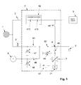
- Fig.1 shows an embodiment of an additional device according to the invention 4. This comprises connections for a first counter 2, which is designed as in particular as a feed-in counter and a second counter 3, which is designed in particular as a reference counter.
- the additional device 4 is connected by the feed meter 2 and the reference counter 3.
- one or more own generating plant 5 for example, solar generator with solar inverter
- the consumer 6 and optionally also a generator 8 are connected.
- the island inverter can consist of one or more parallel-connected island inverters.
- the network monitoring (ENS) that may be present in the in-house generating plant will be shut down as soon as the connection of the own generating plant 5 to the auxiliary device 4 has taken place.
- the island inverter 7 is on its DC side with an energy storage, eg. B. a battery 71, connected.
- the island inverter 7 may have an internal galvanic isolation between AC and DC side. This separation can be realized via a transformer which is operated at line frequency or via one or more high-frequency transformers.
- the island inverter 7 is advantageously designed as an H-bridge of semiconductor switches. These semiconductor switches may consist of MOS transistors, IGBT transistors or GTO thyristors.
- the island inverter 7 is inventively designed such that in case of a short circuit in load circuits during island operation existing overcurrent protection devices of the load circuits are triggered.
- the contactor 45 is controlled such that in the event of a short circuit in a load circuit and associated breakdown of the voltage at node 9, the contactor contacts remain closed until the short-circuit current of the island inverter 7, the associated overcurrent protective device of the load circuit triggers and thus the voltage in the node 9 is restored.
- the additional device 4 contains an interface unit 41. This unit is used to link the island inverter or inverters 7 with the sensors and actuators in the auxiliary device 4.
- a suitable data bus for example CAN bus
- the one or more self-generation plants are connected via the automatic separation point 42 to the feed-in counter 2.
- This separation point contains at least one contactor 411; but it may have another contactor 412 in series with this contactor.
- the contactors 411 and 412 can be designed as one-pole or all-pole.
- the consumers 6 are connected via the transfer contactor 43 to the network 1.
- the contactor 44 connects the self-generating system 5 via the node 9 with the consumers 6 when the transfer gate 43 is opened and the system runs in island mode.
- the contactor 45 connects the island inverter 7 via the node 9 with the consumers 6.
- the contactor 46 connects a generator 8 via the node 9 with the consumers 6.
- the additional device 4 contains at least the following measured value captures: mains voltage measurement 47, AC voltage measurement stand-alone inverter 49, AC current measurement 50.
- a generator voltage measurement 48 may be present.
- the contactors 411, 412, 43 and 45 are closed, the contactors 44 and 46 are open.
- the consumers 6 are supplied from the network 1 via the reference counter 3 with energy.
- the self-generation plants 5 feed energy into the public network 1 via the feed-in counter 2.
- the island inverter 7 charges the energy storage 71. In this case, only a trickle charge with low energy consumption is usually required when the energy store is charged.
- the stand-alone inverter 7 With the aid of measured values for line voltage and line current and a suitable anti-islanding method, the stand-alone inverter 7 constantly monitors the network parameters of the supply network and can thus reliably detect whether an island network is present or not.
- the island inverter 7 operates voltage-controlled.
- the internal bridge voltage in the stand-alone inverter 7 is controlled such that it is adjusted in magnitude and phase with respect to the voltage at the node so that the voltage at the node results as desired and a predetermined battery charging current is set.
- the stand-alone inverter If a defect or a temporary error condition occurs in the stand-alone inverter, it can be disconnected via the contactor 45 from the connection point 9. If the error condition is eliminated, it can synchronize itself again with the aid of the voltage measurements 47 and 49 to the voltage at the connection point 9 and resume the charging operation of the energy store 71.
- the stand-alone inverter 7 If the network 1 is switched off, there is a short circuit in the vicinity, or the power supply in the public grid collapses, this is detected by the stand-alone inverter 7.
- the island inverter now tries to keep the voltage at the node 9 stable via its voltage regulation.
- the contactors 411, 412 and 43 are opened. If by the conditions during the Transition state of the current from the island inverter 7 exceeds a certain maximum, the island inverter 7 limits this current to this maximum value, so that the internal components of the island inverter are not overloaded.
- the voltage at the node 9 then drops accordingly. As soon as the above-mentioned contactors are opened, the current only flows into the consumers 6. The voltage at the connection point 9 again reaches its nominal value.
- the contactor 44 is closed, so that the self-generating system can automatically synchronize to the island grid at node 9. Now the developed island grid can continue to be operated as long as the self-generation system provides enough energy on average. Variations in production and consumption are compensated by the island inverter 7 and its energy storage 71.
- an existing generator 8 (e.g., a diesel generator) may be connected via a contactor 46.
- the island inverter synchronizes with the aid of the generator voltage measurement 48 and the voltage measurement 49, the voltage in the node 9 to the output voltage of the generator 8. After synchronization, the generator contactor 46 is closed.
- the contactor 44 is first opened.
- the self-generation system switches then off.
- the voltage at the node 9 is synchronized with the voltage in the network 1 and the transfer contactor 43 is closed.
- the contactors 411 and 412 are closed, so that the self-generating system 5 can again go into operation via the feed meter 2 on the grid.
- the consumers 6 are supplied from the network and the self-generating system 5 feeds into the network 1.
- the transfer contactor 43 can be designed as an opener or consist of semiconductor switches. It can be controlled so that it is always closed in the event that the auxiliary device is defective when mains voltage is applied. This can ensure that the consumers are not disconnected from the mains if there is a defect in the ancillary equipment.
- All components of the additional device 4 can be arranged in a suitable box, in one or more control cabinets in the in-house generating plant 5 or in the island inverter 7.
- the island inverter 7 and the energy storage 71 are part of the additional device. 4
- the consumers 6 can be completely supplied by the own generating plant 5, as long as the power generation is greater than or equal to the consumption. With the energy storage only the differential energy between generation and consumption needs to be exchanged. This increases the efficiency of the overall system as an advantage of the AC coupling.
- the self-generation plant is preferably a PV system with an associated PV inverter. Furthermore, it can be a variable-speed wind energy plant with a PM generator (permanent synchronous generator).
- Fig.2 shows the formation of the system, wherein the transfer contactor 43 is formed so that when switching from mains parallel operation for island operation, the pole of the contactor, which is connected to the neutral of the node 9 is switched from the neutral conductor of the network to PE.
- Fig. 3 shows the formation of the system with several (n) island inverters and several (m) self-generating plants on one phase.
- the island inverters can be linked with each other and with the interface unit 41 via a suitable data bus connection.
- Fig. 4 shows the formation of the system, in a three-phase connection to the public power grid and an island inverter per phase.
- Fig. 5 shows the formation of the system, in a three-phase connection to the public power grid and a three-phase stand-alone inverter.
- Fig. 6 shows the formation of the system, wherein the three-phase transfer contactor 43 is designed so that when switching from mains parallel operation to isolated operation, the pole of the contactor, which is connected to the neutral of the node 9, can be switched from the neutral of the network to PE.
- the switching can also be realized by multiple contactors.
- Fig. 7 shows the formation of the system in a three-phase connection to the public power grid and more than one island inverters per phase. At each phase are 0 to m
- Own generation plants connected. It is also possible to connect 0 to m three-phase self-generation plants.
- Fig. 8 shows the formation of the system in a three-phase connection to the public power grid and more than a three-phase island inverter. 0 to m self-generation plants are connected to each phase. It is also possible to connect 0 to m three-phase self-generation plants.
- the self-generation plants can be designed with different modes for island operation and grid parallel operation.
- a switchover between the modes can take place.
- a further improved stability in off-grid operation can be achieved.
- the switching is designed so that in case of failure or disruption of the data connection between the own generating plant and the additional device, the own generation plant switches to the operating mode "grid parallel operation" or remains in this.
- the additional device can receive data from the responsible grid operator. If appropriate arrangements exist with the utility operator, the ancillary equipment can use this data to exchange reactive and / or real power with the public grid to stabilize the voltage at the tie point. As a result, z. B. caused by the feed of the power generation plant overvoltages or caused by large consumers undervoltages are avoided at the point of connection.
- All switching elements can be designed both as contactors and as relays or printed circuit board equipped relays.
- the self-generating system may consist of a wind turbine with a synchronous generator, PM generator or an asynchronous generator and an inverter, a wind turbine with a grid-connected synchronous or asynchronous generator, a fuel cell with an associated inverter.
- the self-generation plant can be a hydroelectric power station with a grid-connected synchronous or asynchronous generator or a variable-speed hydropower plant with a PM generator, a synchronous generator or an asynchronous generator and an associated grid inverter.
- the self-generating system of an internal combustion engine with a grid-connected synchronous or asynchronous generator, a variable-speed combustion engine with a PM generator, a synchronous generator or an asynchronous generator and associated network inverter consist.
- the self-generating system may consist of a fuel cell with an associated inverter or be a different type of self-generating system.
- the backup power system is operated in parallel to the own generation plant, to the consumers and public utility networks, so that a modular expandability and a problem-free addition of existing facilities is possible.
- Existing self-generation plants can be modularly expandable to replacement power supplies.
- the power of the backup power supply can be subsequently increased in a simple manner.
- An AC-side parallel connection of self-generation plant, public power grid, consumers and backup power supply can be given.
- the supply of the consumer can not be interrupted for more than 30 ms.
- the extra power needed to provide an uninterruptible power supply can be minimal.
- the energy fed into the public power grid by the in-house power generation plant can not be reduced by the additional equipment.
Landscapes
- Engineering & Computer Science (AREA)
- Power Engineering (AREA)
- Business, Economics & Management (AREA)
- Emergency Management (AREA)
- Supply And Distribution Of Alternating Current (AREA)
- Stand-By Power Supply Arrangements (AREA)
Priority Applications (6)
| Application Number | Priority Date | Filing Date | Title |
|---|---|---|---|
| EP07003991.2A EP1965483B1 (fr) | 2007-02-27 | 2007-02-27 | Circuit pour la connexion d'une installation de génération d'énegie au réseau électrique |
| US12/009,975 US7800248B2 (en) | 2007-02-27 | 2008-01-23 | Backup power system |
| TW097105203A TWI367618B (en) | 2007-02-27 | 2008-02-14 | Backup power system and method for operating the same |
| KR1020080016110A KR100997314B1 (ko) | 2007-02-27 | 2008-02-22 | 백업 전원시스템 |
| AU2008200885A AU2008200885B2 (en) | 2007-02-27 | 2008-02-26 | Backup power system |
| CN2008100826035A CN101257223B (zh) | 2007-02-27 | 2008-02-27 | 后备电力系统 |
Applications Claiming Priority (1)
| Application Number | Priority Date | Filing Date | Title |
|---|---|---|---|
| EP07003991.2A EP1965483B1 (fr) | 2007-02-27 | 2007-02-27 | Circuit pour la connexion d'une installation de génération d'énegie au réseau électrique |
Publications (2)
| Publication Number | Publication Date |
|---|---|
| EP1965483A1 true EP1965483A1 (fr) | 2008-09-03 |
| EP1965483B1 EP1965483B1 (fr) | 2015-07-08 |
Family
ID=38430579
Family Applications (1)
| Application Number | Title | Priority Date | Filing Date |
|---|---|---|---|
| EP07003991.2A Active EP1965483B1 (fr) | 2007-02-27 | 2007-02-27 | Circuit pour la connexion d'une installation de génération d'énegie au réseau électrique |
Country Status (6)
| Country | Link |
|---|---|
| US (1) | US7800248B2 (fr) |
| EP (1) | EP1965483B1 (fr) |
| KR (1) | KR100997314B1 (fr) |
| CN (1) | CN101257223B (fr) |
| AU (1) | AU2008200885B2 (fr) |
| TW (1) | TWI367618B (fr) |
Cited By (28)
| Publication number | Priority date | Publication date | Assignee | Title |
|---|---|---|---|---|
| EP2228895A1 (fr) * | 2009-03-09 | 2010-09-15 | SMA Solar Technology AG | Onduleur avec interface au réseau d'alimentation |
| DE202010008123U1 (de) | 2010-07-20 | 2010-10-21 | Sma Solar Technology Ag | Umschalteinrichtung |
| DE102009035399A1 (de) * | 2009-07-30 | 2011-02-03 | Löffler, Martin | Schaltungsanordnung zur Stromlenkung |
| DE102009047980A1 (de) | 2009-10-01 | 2011-04-07 | Solarconsult Ag | Freischaltsteuergerät |
| DE102010000502A1 (de) | 2010-02-22 | 2011-08-25 | SMA Solar Technology AG, 34266 | Umschalteinrichtung und Netzersatzanlage |
| DE102010040007A1 (de) * | 2010-08-31 | 2012-03-01 | Sma Solar Technology Ag | Selbstständiges Verbinden einer autarken Einheit mit einem mehrere autarke Einheiten verbindenden Wechselstromnetz |
| DE102010052331A1 (de) | 2010-11-25 | 2012-05-31 | Polyma Energiesysteme Gmbh | Lokales elektrisches System |
| WO2012101258A1 (fr) | 2011-01-28 | 2012-08-02 | Sma Solar Technology Ag | Installation d'alimentation électrique locale |
| DE102011056138A1 (de) | 2011-12-07 | 2013-06-13 | Refusol Gmbh | System zur Nutzung und Speicherung elektrischer Energie verschiedenartiger Energiequellen |
| DE102011056135A1 (de) | 2011-12-07 | 2013-06-13 | Refusol Gmbh | Energieerzeugungsanlage mit einem Energiespeichersystem und zugehöriges Betriebsverfahren |
| DE102012002601A1 (de) | 2012-02-13 | 2013-08-14 | Refusol Gmbh | Energieerzeugungsanlage mit kostengünstigem Energiespeichersystem |
| DE102012002599A1 (de) | 2012-02-13 | 2013-08-14 | Refusol Gmbh | Energieerzeugungsanlage mit Wechselrichter und Energiespeichersystem |
| DE102012102766B3 (de) * | 2012-03-30 | 2013-09-05 | Sma Solar Technology Ag | Netzersatzanlage und Erdungseinrichtung für eine Netzersatzanlage |
| DE102012011708A1 (de) | 2012-06-13 | 2013-12-19 | E3/Dc Gmbh | Wechselrichtervorrichtung mit Notstrombetrieb |
| US8716885B2 (en) | 2011-10-19 | 2014-05-06 | Thomas & Betts International, Inc. | Disconnect switch for distributed energy system |
| WO2014096009A1 (fr) * | 2012-12-21 | 2014-06-26 | Sma Solar Technology Ag | Installation auxiliaire d'alimentation et procédé de séparation d'un réseau local de distribution d'énergie d'un réseau supérieur d'alimentation en énergie |
| WO2015000952A1 (fr) | 2013-07-03 | 2015-01-08 | Sma Solar Technology Ag | Procédé de fonctionnement d'un convertisseur pour batterie et convertisseur bidirectionnel pour batterie |
| DE102014200464A1 (de) | 2014-01-14 | 2015-07-16 | Robert Bosch Gmbh | Vorrichtung und Verfahren zum kombinierten Betreiben eines elektrischen Verbrauchers mit Netzstrom und/oder elektrischer Energie aus einer unabhängigen Energiequelle |
| US9190871B2 (en) | 2011-10-19 | 2015-11-17 | Thomas & Betts International, Llc | Distributed energy system disconnect switch with mechanical isolation |
| EP2808971A4 (fr) * | 2012-01-27 | 2016-04-20 | Mitsubishi Electric Corp | Dispositif de commutation d'alimentation électrique et tableau de commutation |
| DE102015102468B3 (de) * | 2015-02-20 | 2016-06-16 | Sma Solar Technology Ag | Netzersatzanlage und Erdungseinrichtung für eine Netzersatzanlage |
| DE102016105662A1 (de) * | 2016-03-29 | 2017-10-05 | Wobben Properties Gmbh | Verfahren zum Einspeisen elektrischer Leistung in ein elektrisches Versorgungsnetz mit einem Windpark sowie Windpark |
| EP3232529A1 (fr) | 2016-04-14 | 2017-10-18 | DET International Holding Limited | Agencement d'alimentation électrique |
| DE102018104518A1 (de) * | 2018-02-28 | 2019-08-29 | Voith Patent Gmbh | Kombiniertes Kraftwerk und Verfahren zum Betrieb |
| DE112013003055B4 (de) | 2012-06-18 | 2019-12-19 | Tsubakimoto Chain Co. | Energiesteuervorrichtung |
| WO2021023604A1 (fr) * | 2019-08-06 | 2021-02-11 | Sma Solar Technology Ag | Système d'alimentation en énergie doté d'un dispositif de couplage |
| DE102020129918A1 (de) | 2020-11-12 | 2022-05-12 | Sma Solar Technology Ag | Vorrichtung und Verfahren zur Erdung eines Gleichspannungsnetzes |
| DE102021201225A1 (de) | 2021-02-09 | 2022-08-11 | Ronny Kirschner | Adapter und Einspeisenetzwerk zum Anschluss eines Stromspeichers an ein Stromnetz |
Families Citing this family (78)
| Publication number | Priority date | Publication date | Assignee | Title |
|---|---|---|---|---|
| US8987939B2 (en) * | 2007-11-30 | 2015-03-24 | Caterpillar Inc. | Hybrid power system with variable speed genset |
| TW200943271A (en) * | 2008-04-02 | 2009-10-16 | Novatek Microelectronics Corp | Memory-saving display device |
| US7944068B2 (en) * | 2008-06-30 | 2011-05-17 | General Electric Company | Optimizing converter protection for wind turbine generators |
| US9231438B2 (en) | 2008-10-01 | 2016-01-05 | Aspen Avionics, Inc. | Airborne power system disconnect system and method |
| ES2407631T3 (es) | 2008-11-04 | 2013-06-13 | Nokia Siemens Networks Oy | Gestión de sobrecargas y traspasos en una red de comunicaciones |
| US7683603B1 (en) * | 2008-11-17 | 2010-03-23 | Eaton Corporation | Automatic disconnect system, transfer system and method |
| US8352091B2 (en) * | 2009-01-02 | 2013-01-08 | International Business Machines Corporation | Distributed grid-interactive photovoltaic-based power dispatching |
| WO2010111433A2 (fr) | 2009-03-25 | 2010-09-30 | Powergetics, Inc. | Convertisseur d'énergie bidirectionnel |
| ITTO20090375A1 (it) * | 2009-05-13 | 2010-11-14 | Rosa Mario La | Sorgente da fonte solare con funzione di filtro attivo e di alimentazione di continuita' |
| US7965485B2 (en) * | 2009-06-12 | 2011-06-21 | Ferraz Shawmut S.A. | Circuit protection device for photovoltaic systems |
| TW201112565A (en) | 2009-06-29 | 2011-04-01 | Powergetics Inc | High speed feedback for power load reduction using a variable generator |
| TW201112578A (en) | 2009-06-29 | 2011-04-01 | Powergetics Inc | High speed feedback adjustment of power charge/discharge from energy storage system |
| US8648495B2 (en) * | 2009-11-23 | 2014-02-11 | Ses Technologies, Llc | Smart-grid combination power system |
| US8653823B2 (en) * | 2010-06-04 | 2014-02-18 | Abb Inc. | Detection of welded switch contacts in a line converter system |
| CN102075001A (zh) * | 2010-06-25 | 2011-05-25 | 广东省电力调度中心 | 适用于小水电丰富地区的智能型进线备自投方法及装置 |
| TWI456857B (zh) * | 2010-10-14 | 2014-10-11 | Atomic Energy Council | 具備智慧型調度管理之電網系統 |
| US9300141B2 (en) * | 2010-11-18 | 2016-03-29 | John J. Marhoefer | Virtual power plant system and method incorporating renewal energy, storage and scalable value-based optimization |
| US9509139B1 (en) * | 2010-12-28 | 2016-11-29 | Reliance Controls Corporation | Transfer switch for automatically switching neutrals for one or more loads between two electrical sources of power |
| TWI422120B (zh) * | 2011-01-12 | 2014-01-01 | Zippy Tech Corp | A backup power system that operates according to load regulation |
| MX2013008462A (es) | 2011-01-23 | 2013-08-29 | Alpha Tech Inc | Suministros de energia ininterrumpible para uso en una red de distribucion. |
| EP2528183B1 (fr) * | 2011-03-04 | 2014-04-02 | SBU Photovoltaik GmbH | Procédé et dispositif d'alimentation en courant |
| JP5311153B2 (ja) * | 2011-03-15 | 2013-10-09 | オムロン株式会社 | 電力制御装置および電力制御方法 |
| EP2512000B1 (fr) | 2011-04-15 | 2022-03-02 | ABB Schweiz AG | Systèmes et convertisseurs de puissance reconfigurables |
| CN102185333B (zh) * | 2011-04-19 | 2013-05-08 | 河南省电力公司电力科学研究院 | 双向变流器在微电网中实现并离网双模式运行的方法 |
| US10840735B1 (en) * | 2011-05-26 | 2020-11-17 | J. Carl Cooper | Power source load control |
| US11183843B1 (en) | 2011-05-26 | 2021-11-23 | J. Carl Cooper | Power source load control |
| US11522365B1 (en) | 2011-05-26 | 2022-12-06 | J. Carl Cooper | Inverter power source load dependent frequency control and load shedding |
| KR101067594B1 (ko) * | 2011-05-27 | 2011-09-27 | 박경선 | 대형빌딩 전기설비 무정전시스템 |
| CN102214953A (zh) * | 2011-06-17 | 2011-10-12 | 北京中泰恒信电力技术有限公司 | 集装箱式配电系统 |
| TW201306441A (zh) * | 2011-07-28 | 2013-02-01 | Pi-Zhong Wang | 雙電源安全切換電路 |
| JP5792552B2 (ja) * | 2011-08-03 | 2015-10-14 | ラピスセミコンダクタ株式会社 | 電源供給制御システム及び半導体集積回路 |
| US9318861B2 (en) * | 2011-11-02 | 2016-04-19 | ConnectDER LLC | Meter collar for plug-in connection of distributed power generation |
| CN102510124A (zh) * | 2011-11-25 | 2012-06-20 | 北京金风科创风电设备有限公司 | 用于微网的从孤岛模式切换到并网模式的模式切换方法 |
| US8774977B2 (en) | 2011-12-29 | 2014-07-08 | Stem, Inc. | Multiphase electrical power construction and assignment at minimal loss |
| US8803570B2 (en) | 2011-12-29 | 2014-08-12 | Stem, Inc | Multiphase electrical power assignment at minimal loss |
| US8922192B2 (en) | 2011-12-30 | 2014-12-30 | Stem, Inc. | Multiphase electrical power phase identification |
| CN102621967B (zh) * | 2012-04-10 | 2014-07-30 | 上海科泰电源股份有限公司 | 一种数据机房智能电源电立方的集中监控系统 |
| US9406094B2 (en) | 2012-08-14 | 2016-08-02 | Stem Inc. | Method and apparatus for delivering power using external data |
| US10782721B2 (en) | 2012-08-27 | 2020-09-22 | Stem, Inc. | Method and apparatus for balancing power on a per phase basis in multi-phase electrical load facilities using an energy storage system |
| US11454999B2 (en) | 2012-08-29 | 2022-09-27 | Stem, Inc. | Method and apparatus for automatically reconfiguring multi-phased networked energy storage devices at a site |
| US10756543B2 (en) | 2012-09-13 | 2020-08-25 | Stem, Inc. | Method and apparatus for stabalizing power on an electrical grid using networked distributed energy storage systems |
| US9634508B2 (en) | 2012-09-13 | 2017-04-25 | Stem, Inc. | Method for balancing frequency instability on an electric grid using networked distributed energy storage systems |
| US10389126B2 (en) | 2012-09-13 | 2019-08-20 | Stem, Inc. | Method and apparatus for damping power oscillations on an electrical grid using networked distributed energy storage systems |
| US10693294B2 (en) | 2012-09-26 | 2020-06-23 | Stem, Inc. | System for optimizing the charging of electric vehicles using networked distributed energy storage systems |
| WO2014187133A1 (fr) * | 2013-05-22 | 2014-11-27 | 江苏省电力公司常州供电公司 | Système de contrôle intelligent pour appareil de commutation automatique d'alimentation électrique de secours |
| CN103618377B (zh) * | 2013-12-03 | 2015-10-14 | 长园深瑞继保自动化有限公司 | 用于接有小电源的备自投装置系统及备自投方法 |
| KR20150069613A (ko) * | 2013-12-13 | 2015-06-24 | 주식회사 엘지씨엔에스 | 무정전 전원 공급 장치(ups)를 활용한 에너지 저장 시스템 |
| CN103683421A (zh) * | 2013-12-14 | 2014-03-26 | 苏州市新虞仪表成套设备有限公司 | 数控机床后备电源 |
| JP6160481B2 (ja) * | 2013-12-27 | 2017-07-12 | ソニー株式会社 | 電源装置、電源システムおよび電源制御方法 |
| US9876354B2 (en) * | 2014-05-21 | 2018-01-23 | Eaton Corporation | UPS systems and methods using coordinated static switch and inverter operation for generator walk-in |
| US10103574B2 (en) | 2014-06-21 | 2018-10-16 | Microsoft Technology Licensing, Llc | Controlled concurrent utilization of multiple power supplies |
| US10447040B2 (en) | 2014-10-15 | 2019-10-15 | Cummins Power Generation Ip, Inc. | Programmable inverter for controllable grid response |
| KR101691618B1 (ko) * | 2014-12-29 | 2016-12-30 | 주식회사 엘지씨엔에스 | 전환 가능 무정전 전원 공급 시스템 및 이의 배터리 충전 방법 |
| KR101671591B1 (ko) * | 2014-12-29 | 2016-11-01 | 주식회사 엘지씨엔에스 | 충전 방지 가능 무정전 전원 공급 시스템 및 무정전 전원 공급 시스템의 제어 방법 |
| US9798337B2 (en) * | 2015-03-17 | 2017-10-24 | Diwin Technology Co., Ltd. | Control system using power line communication |
| CN106160176A (zh) * | 2015-04-28 | 2016-11-23 | 台达电子企业管理(上海)有限公司 | 配电系统和电气系统 |
| CN104852606A (zh) * | 2015-06-03 | 2015-08-19 | 吉林瀚丰电气有限公司 | 一种实时监控智能投切的低压整流柜 |
| TWI542114B (zh) * | 2015-06-17 | 2016-07-11 | 台達電子工業股份有限公司 | 太陽能逆變器並網系統及三相並網方法 |
| AU2016321418A1 (en) | 2015-09-13 | 2018-04-05 | Alpha Technologies Services, Inc. | Power control systems and methods |
| US10230260B2 (en) | 2015-09-23 | 2019-03-12 | Abb Schweiz Ag | Fast utility disconnect switch for single conversion UPS |
| US10381867B1 (en) | 2015-10-16 | 2019-08-13 | Alpha Technologeis Services, Inc. | Ferroresonant transformer systems and methods with selectable input and output voltages for use in uninterruptible power supplies |
| WO2017094093A1 (fr) * | 2015-12-01 | 2017-06-08 | 東芝三菱電機産業システム株式会社 | Dispositif d'alimentation électrique sans coupure |
| DE102015122636B4 (de) * | 2015-12-22 | 2017-07-13 | Sma Solar Technology Ag | Wechselrichter mit Netztrennstelle und Isolationswiderstandsmessung sowie Verfahren zur Messung eines Isolationswiderstandes |
| US10424933B2 (en) * | 2016-08-10 | 2019-09-24 | Tesla, Inc. | Automatic smart transfer switch for energy generation systems |
| KR102183993B1 (ko) * | 2016-09-23 | 2020-11-27 | 삼성에스디아이 주식회사 | 전력 공급 장치 |
| US10148094B2 (en) * | 2016-10-20 | 2018-12-04 | Caterpillar Inc. | Hybrid electrical power generation system and method |
| JP7113267B2 (ja) * | 2017-06-02 | 2022-08-05 | パナソニックIpマネジメント株式会社 | 蓄電システム |
| US11368100B2 (en) * | 2017-07-13 | 2022-06-21 | Kohler Co. | Generator and battery backup with conversion device |
| CA3069966A1 (fr) | 2017-07-14 | 2019-01-17 | Alpha Technologies Services, Inc. | Systemes et procedes d'alimentation en courant alternatif a regulation de tension |
| CN107612394B (zh) * | 2017-09-12 | 2019-11-22 | 爱士惟新能源技术(江苏)有限公司 | 用于具有h5拓扑结构的逆变器装置的控制处理方法 |
| US11362519B2 (en) | 2018-04-19 | 2022-06-14 | Flexgen Power Systems, Inc. | Apparatus and methods for soft grid interconnection of distributed generation assets |
| CN108599316A (zh) * | 2018-05-25 | 2018-09-28 | 辰逸腾工业(苏州)有限公司 | 一种用于锂电池组的电气控制装置 |
| TWI710192B (zh) * | 2019-07-26 | 2020-11-11 | 許俊吉 | 用於太陽能電力傳送的防災斷路系統 |
| US11128140B2 (en) * | 2019-08-28 | 2021-09-21 | A. M. Solar, Inc. | Automatic switch for single- or split-phase AC electrical power |
| US11456688B2 (en) | 2020-11-30 | 2022-09-27 | General Electric Renovables Espana, S.L. | Systems and methods for operating a power generating asset |
| US20230069168A1 (en) * | 2021-09-01 | 2023-03-02 | Schweitzer Engineering Laboratories, Inc. | Systems and methods for operating an islanded distribution substation using inverter power generation |
| US11876458B2 (en) * | 2021-09-23 | 2024-01-16 | Apple Inc. | Hybrid charger and inverter system |
| DE102022116671A1 (de) * | 2022-07-04 | 2024-01-04 | Sma Solar Technology Ag | Leistungswandler, verfahren zum betrieb eines leistungswandlers und system mit einer dc-energiequelle, einem dc-netz und einem leistungswandler |
Citations (5)
| Publication number | Priority date | Publication date | Assignee | Title |
|---|---|---|---|---|
| EP0817350A2 (fr) | 1996-06-24 | 1998-01-07 | SANYO ELECTRIC Co., Ltd. | Système d'alimentation avec interconnexion de système |
| US6304006B1 (en) | 2000-12-28 | 2001-10-16 | Abb T&D Technology Ltd. | Energy management uninterruptible power supply system |
| US20020143438A1 (en) | 2001-03-27 | 2002-10-03 | Sanyo Electric Co., Ltd | Distributed power generation system, and power supply system and power supply method utilizing the same |
| WO2003077398A2 (fr) | 2002-03-08 | 2003-09-18 | Aloys Wobben | Reseau separe et son mode de fonctionnement |
| US6949843B2 (en) | 2003-07-11 | 2005-09-27 | Morningstar, Inc. | Grid-connected power systems having back-up power sources and methods of providing back-up power in grid-connected power systems |
Family Cites Families (13)
| Publication number | Priority date | Publication date | Assignee | Title |
|---|---|---|---|---|
| JP4076721B2 (ja) * | 1997-11-24 | 2008-04-16 | エイチ. ウィルス、ロバート | 分散型発電用耐単独運転方法および装置 |
| PL344336A1 (en) * | 1998-05-19 | 2001-11-05 | Sure Power Corp | Power system |
| US6942843B2 (en) | 2001-03-28 | 2005-09-13 | Council Of Scientific And Industrial Research | Preparation, characterization, ESR and PAS studies of Cu0.5NbAlP3O12 (CNP) and HNbAlP3O12 (HNP) |
| US6630752B2 (en) * | 2001-09-12 | 2003-10-07 | Qualmag, Inc. | Uninterruptible transfer switch |
| JP2005507169A (ja) * | 2001-10-25 | 2005-03-10 | サンディア コーポレーション | 交流光起電ビルディングブロック |
| AU2002357670A1 (en) * | 2001-10-26 | 2003-05-12 | Youtility, Inc. | Anti-islanding techniques for distributed power generation |
| US6849967B2 (en) * | 2002-04-19 | 2005-02-01 | Eaton Corporation | Automatic transfer switch for microturbine and method of operation |
| US20040070281A1 (en) * | 2002-10-15 | 2004-04-15 | Carolina Tractor & Equipment Company | Method and apparatus for isolating a cogeneration system from a utility source |
| JP4071675B2 (ja) * | 2003-05-27 | 2008-04-02 | 東芝三菱電機産業システム株式会社 | 無停電電源装置の並列運転システム |
| US7183667B2 (en) * | 2003-12-19 | 2007-02-27 | Square D Company | Method and apparatus for power inverter synchronization |
| US20060071554A1 (en) * | 2004-09-27 | 2006-04-06 | Mcnamara James L | Electrical power distribution system and method thereof |
| US7906870B2 (en) * | 2006-10-13 | 2011-03-15 | Pv Powered, Inc. | System and method for anti-islanding, such as anti-islanding for a grid-connected photovoltaic inverter |
| US7723863B2 (en) * | 2007-07-20 | 2010-05-25 | Eaton Corporation | Power systems and methods using an uniterruptible power supply to transition to generator-powered operation |
-
2007
- 2007-02-27 EP EP07003991.2A patent/EP1965483B1/fr active Active
-
2008
- 2008-01-23 US US12/009,975 patent/US7800248B2/en active Active
- 2008-02-14 TW TW097105203A patent/TWI367618B/zh not_active IP Right Cessation
- 2008-02-22 KR KR1020080016110A patent/KR100997314B1/ko active IP Right Grant
- 2008-02-26 AU AU2008200885A patent/AU2008200885B2/en active Active
- 2008-02-27 CN CN2008100826035A patent/CN101257223B/zh active Active
Patent Citations (5)
| Publication number | Priority date | Publication date | Assignee | Title |
|---|---|---|---|---|
| EP0817350A2 (fr) | 1996-06-24 | 1998-01-07 | SANYO ELECTRIC Co., Ltd. | Système d'alimentation avec interconnexion de système |
| US6304006B1 (en) | 2000-12-28 | 2001-10-16 | Abb T&D Technology Ltd. | Energy management uninterruptible power supply system |
| US20020143438A1 (en) | 2001-03-27 | 2002-10-03 | Sanyo Electric Co., Ltd | Distributed power generation system, and power supply system and power supply method utilizing the same |
| WO2003077398A2 (fr) | 2002-03-08 | 2003-09-18 | Aloys Wobben | Reseau separe et son mode de fonctionnement |
| US6949843B2 (en) | 2003-07-11 | 2005-09-27 | Morningstar, Inc. | Grid-connected power systems having back-up power sources and methods of providing back-up power in grid-connected power systems |
Non-Patent Citations (1)
| Title |
|---|
| SMARTE ENERGIEKONZEPTE, August 2006 (2006-08-01) |
Cited By (47)
| Publication number | Priority date | Publication date | Assignee | Title |
|---|---|---|---|---|
| US8779630B2 (en) | 2009-03-09 | 2014-07-15 | Sma Solar Technology Ag | Power generation system and inverter for feeding power into a three-phase grid |
| EP2228895A1 (fr) * | 2009-03-09 | 2010-09-15 | SMA Solar Technology AG | Onduleur avec interface au réseau d'alimentation |
| DE102009035399A1 (de) * | 2009-07-30 | 2011-02-03 | Löffler, Martin | Schaltungsanordnung zur Stromlenkung |
| DE102009047980A1 (de) | 2009-10-01 | 2011-04-07 | Solarconsult Ag | Freischaltsteuergerät |
| DE202009018199U1 (de) | 2009-10-01 | 2011-06-09 | changetec GmbH, 71691 | Freischaltsteuergerät |
| DE102010000502A1 (de) | 2010-02-22 | 2011-08-25 | SMA Solar Technology AG, 34266 | Umschalteinrichtung und Netzersatzanlage |
| DE102010000502B4 (de) | 2010-02-22 | 2022-12-22 | Sma Solar Technology Ag | Umschalteinrichtung und Netzersatzanlage |
| DE202010008123U1 (de) | 2010-07-20 | 2010-10-21 | Sma Solar Technology Ag | Umschalteinrichtung |
| DE102010040007A1 (de) * | 2010-08-31 | 2012-03-01 | Sma Solar Technology Ag | Selbstständiges Verbinden einer autarken Einheit mit einem mehrere autarke Einheiten verbindenden Wechselstromnetz |
| DE102010040007B4 (de) | 2010-08-31 | 2018-10-04 | Sma Solar Technology Ag | Selbstständiges Verbinden einer autarken Einheit mit einem mehrere autarke Einheiten verbindenden Wechselstromnetz |
| DE102010052331A1 (de) | 2010-11-25 | 2012-05-31 | Polyma Energiesysteme Gmbh | Lokales elektrisches System |
| DE102010052331B4 (de) | 2010-11-25 | 2019-08-14 | Polyma Energiesysteme Gmbh | Lokales elektrisches System |
| AU2012210486B2 (en) * | 2011-01-28 | 2016-07-07 | Sma Solar Technology Ag | Local power supply installation |
| DE102011000394A1 (de) | 2011-01-28 | 2012-08-02 | Sma Solar Technology Ag | Lokale Energieversorgungsanlage |
| WO2012101258A1 (fr) | 2011-01-28 | 2012-08-02 | Sma Solar Technology Ag | Installation d'alimentation électrique locale |
| US8716885B2 (en) | 2011-10-19 | 2014-05-06 | Thomas & Betts International, Inc. | Disconnect switch for distributed energy system |
| US9190871B2 (en) | 2011-10-19 | 2015-11-17 | Thomas & Betts International, Llc | Distributed energy system disconnect switch with mechanical isolation |
| DE102011056135B4 (de) * | 2011-12-07 | 2015-05-13 | Refusol Gmbh | Energieerzeugungsanlage mit einem Energiespeichersystem und zugehöriges Betriebsverfahren |
| WO2013083521A1 (fr) | 2011-12-07 | 2013-06-13 | Refusol Gmbh | Système pour l'utilisation et le stockage d'énergie électrique de sources d'énergie de nature différente |
| DE102011056135A1 (de) | 2011-12-07 | 2013-06-13 | Refusol Gmbh | Energieerzeugungsanlage mit einem Energiespeichersystem und zugehöriges Betriebsverfahren |
| DE102011056138A1 (de) | 2011-12-07 | 2013-06-13 | Refusol Gmbh | System zur Nutzung und Speicherung elektrischer Energie verschiedenartiger Energiequellen |
| US9825488B2 (en) | 2012-01-27 | 2017-11-21 | Mitsubishi Electric Corporation | Power supply switching device and switch board |
| EP2808971A4 (fr) * | 2012-01-27 | 2016-04-20 | Mitsubishi Electric Corp | Dispositif de commutation d'alimentation électrique et tableau de commutation |
| DE102012002599B4 (de) * | 2012-02-13 | 2016-03-03 | Refusol Gmbh | Energieerzeugungsanlage mit Wechselrichter und Energiespeichersystem |
| DE102012002599A1 (de) | 2012-02-13 | 2013-08-14 | Refusol Gmbh | Energieerzeugungsanlage mit Wechselrichter und Energiespeichersystem |
| DE102012002601A1 (de) | 2012-02-13 | 2013-08-14 | Refusol Gmbh | Energieerzeugungsanlage mit kostengünstigem Energiespeichersystem |
| WO2013144316A1 (fr) | 2012-03-30 | 2013-10-03 | Sma Solar Technology Ag | Système d' alimentation électrique de secours et dispositif de mise à la terre pour un système d' alimentation électrique de secours |
| DE102012102766B3 (de) * | 2012-03-30 | 2013-09-05 | Sma Solar Technology Ag | Netzersatzanlage und Erdungseinrichtung für eine Netzersatzanlage |
| DE102012011708A1 (de) | 2012-06-13 | 2013-12-19 | E3/Dc Gmbh | Wechselrichtervorrichtung mit Notstrombetrieb |
| DE112013003055B4 (de) | 2012-06-18 | 2019-12-19 | Tsubakimoto Chain Co. | Energiesteuervorrichtung |
| WO2014096009A1 (fr) * | 2012-12-21 | 2014-06-26 | Sma Solar Technology Ag | Installation auxiliaire d'alimentation et procédé de séparation d'un réseau local de distribution d'énergie d'un réseau supérieur d'alimentation en énergie |
| DE102013107012A1 (de) | 2013-07-03 | 2015-01-08 | Sma Solar Technology Ag | Verfahren zum Betrieb eines Batteriewandlers und bidirektionaler Batteriewandler |
| WO2015000952A1 (fr) | 2013-07-03 | 2015-01-08 | Sma Solar Technology Ag | Procédé de fonctionnement d'un convertisseur pour batterie et convertisseur bidirectionnel pour batterie |
| DE102013107012B4 (de) * | 2013-07-03 | 2017-07-13 | Sma Solar Technology Ag | Verfahren zum Betrieb eines Batteriewandlers und bidirektionaler Batteriewandler |
| EP3017523B1 (fr) | 2013-07-03 | 2017-03-22 | SMA Solar Technology AG | Procédé de commande de convertisseur comportant une batterie ainsi que les convertisseurs comprtant une batterie qui sont bidirectionnels |
| DE102014200464A1 (de) | 2014-01-14 | 2015-07-16 | Robert Bosch Gmbh | Vorrichtung und Verfahren zum kombinierten Betreiben eines elektrischen Verbrauchers mit Netzstrom und/oder elektrischer Energie aus einer unabhängigen Energiequelle |
| DE102015102468B3 (de) * | 2015-02-20 | 2016-06-16 | Sma Solar Technology Ag | Netzersatzanlage und Erdungseinrichtung für eine Netzersatzanlage |
| WO2016131620A1 (fr) | 2015-02-20 | 2016-08-25 | Sma Solar Technology Ag | Installation de remplacement de réseau, système de mise à la terre pour une installation de remplacement de réseau et procédé de fonctionnement |
| US10566799B2 (en) | 2016-03-29 | 2020-02-18 | Wobben Properties Gmbh | Method for feeding electrical power into an electricity supply network with a wind park and wind park with black start |
| WO2017167784A1 (fr) | 2016-03-29 | 2017-10-05 | Wobben Properties Gmbh | Procédé d'injection d'énergie électrique dans un réseau d'alimentation électrique au moyen d'un parc éolien et parc éolien équipé d'un démarrage autonome |
| DE102016105662A1 (de) * | 2016-03-29 | 2017-10-05 | Wobben Properties Gmbh | Verfahren zum Einspeisen elektrischer Leistung in ein elektrisches Versorgungsnetz mit einem Windpark sowie Windpark |
| EP3232529A1 (fr) | 2016-04-14 | 2017-10-18 | DET International Holding Limited | Agencement d'alimentation électrique |
| US11139656B2 (en) | 2016-04-14 | 2021-10-05 | Delta Electronics (Thailand) Public Co., Ltd. | Power supply arrangement |
| DE102018104518A1 (de) * | 2018-02-28 | 2019-08-29 | Voith Patent Gmbh | Kombiniertes Kraftwerk und Verfahren zum Betrieb |
| WO2021023604A1 (fr) * | 2019-08-06 | 2021-02-11 | Sma Solar Technology Ag | Système d'alimentation en énergie doté d'un dispositif de couplage |
| DE102020129918A1 (de) | 2020-11-12 | 2022-05-12 | Sma Solar Technology Ag | Vorrichtung und Verfahren zur Erdung eines Gleichspannungsnetzes |
| DE102021201225A1 (de) | 2021-02-09 | 2022-08-11 | Ronny Kirschner | Adapter und Einspeisenetzwerk zum Anschluss eines Stromspeichers an ein Stromnetz |
Also Published As
| Publication number | Publication date |
|---|---|
| TWI367618B (en) | 2012-07-01 |
| CN101257223A (zh) | 2008-09-03 |
| AU2008200885A1 (en) | 2008-09-11 |
| KR20080079596A (ko) | 2008-09-01 |
| TW200849770A (en) | 2008-12-16 |
| KR100997314B1 (ko) | 2010-11-29 |
| EP1965483B1 (fr) | 2015-07-08 |
| AU2008200885B2 (en) | 2010-02-11 |
| US20080203820A1 (en) | 2008-08-28 |
| CN101257223B (zh) | 2011-09-28 |
| US7800248B2 (en) | 2010-09-21 |
Similar Documents
| Publication | Publication Date | Title |
|---|---|---|
| EP1965483B1 (fr) | Circuit pour la connexion d'une installation de génération d'énegie au réseau électrique | |
| EP1841050B1 (fr) | Procédé pour convertir une tension continue en une tension triphasée | |
| EP2924839B1 (fr) | Régime de secours monophasé d'un onduleur triphasé et onduleur correspondant | |
| DE102009025363B4 (de) | Anfahrquelle Wechselrichter | |
| EP2847843B1 (fr) | Installation photovoltaïque et procédé de fonctionnement d'une installation photovoltaïque pour l'alimentation en puissance électrique d'un réseau électrique moyenne tension | |
| DE102008024222A1 (de) | Verfahren und Vorrichtung zur Bereitstellung von Regelleistung im Energieversorgungsbereich zur Frequenzstabilisierung eines elektrischen Netzes | |
| WO2012175332A1 (fr) | Dispositif de commande de la charge des phases d'un réseau triphasé | |
| EP2636144A2 (fr) | Circuit d'entraînement d'un moteur de correction de pitch apte à fonctionner en régime de secours | |
| Alatrash et al. | Enabling large-scale PV integration into the grid | |
| WO2014083082A1 (fr) | Installation de distribution d'énergie équipée d'un dispositif de commande | |
| EP3518367A1 (fr) | Système d'alimentation | |
| DE102011000394A1 (de) | Lokale Energieversorgungsanlage | |
| WO2016207026A1 (fr) | Procédé de stabilisation d'un réseau électrique alternatif | |
| EP2026440A2 (fr) | Procédé et dispositif de préparation d'une puissance de régulation dans le domaine de la distribution d'énergie d'un distributeur d'énergie en vue de la stabilisation de la fréquence d'un réseau électrique | |
| WO2020099055A1 (fr) | Installation de transformation d'un réseau de distribution électrique ainsi que procédé de fonctionnement d'une installation de transformation | |
| DE102018116013B4 (de) | Energieerzeugungsanlage, Wechselrichter und Verfahren zur Vorladung von Gleichspannungs-Zwischenkreisen von Wechselrichtern | |
| DE102012102766B3 (de) | Netzersatzanlage und Erdungseinrichtung für eine Netzersatzanlage | |
| DE102011000459A1 (de) | Verfahren zur Lieferung von Blindstrom mit einem Umrichter sowie Umrichteranordnung und Energieversorgungsanlage | |
| EP4010956A1 (fr) | Système d'alimentation en énergie doté d'un dispositif de couplage | |
| DE202011102374U1 (de) | Energiespeicher- und/oder Versorgungsvorrichtung | |
| DE102010019268A1 (de) | Photovoltaikanlage mit Batterieeinspeisung | |
| DE10131226A1 (de) | Verteilsystem zur Versorgung von Verbrauchern mit einer Wechselspannungs-Niederspannung | |
| DE102020130539B4 (de) | Verfahren zum Betrieb eines Energieversorgungssystems, Energieversorgungssystem und Steuerungseinheit für ein Energieversorgungssystem | |
| WO2002033801A1 (fr) | Systeme de distribution d'energie electrique | |
| DE4017755C2 (fr) |
Legal Events
| Date | Code | Title | Description |
|---|---|---|---|
| PUAI | Public reference made under article 153(3) epc to a published international application that has entered the european phase |
Free format text: ORIGINAL CODE: 0009012 |
|
| 17P | Request for examination filed |
Effective date: 20080107 |
|
| AK | Designated contracting states |
Kind code of ref document: A1 Designated state(s): AT BE BG CH CY CZ DE DK EE ES FI FR GB GR HU IE IS IT LI LT LU LV MC NL PL PT RO SE SI SK TR |
|
| AX | Request for extension of the european patent |
Extension state: AL BA HR MK RS |
|
| AKX | Designation fees paid |
Designated state(s): AT BE BG CH CY CZ DE DK EE ES FI FR GB GR HU IE IS IT LI LT LU LV MC NL PL PT RO SE SI SK TR |
|
| GRAP | Despatch of communication of intention to grant a patent |
Free format text: ORIGINAL CODE: EPIDOSNIGR1 |
|
| INTG | Intention to grant announced |
Effective date: 20150206 |
|
| GRAS | Grant fee paid |
Free format text: ORIGINAL CODE: EPIDOSNIGR3 |
|
| GRAP | Despatch of communication of intention to grant a patent |
Free format text: ORIGINAL CODE: EPIDOSNIGR1 |
|
| INTG | Intention to grant announced |
Effective date: 20150420 |
|
| GRAA | (expected) grant |
Free format text: ORIGINAL CODE: 0009210 |
|
| AK | Designated contracting states |
Kind code of ref document: B1 Designated state(s): AT BE BG CH CY CZ DE DK EE ES FI FR GB GR HU IE IS IT LI LT LU LV MC NL PL PT RO SE SI SK TR |
|
| REG | Reference to a national code |
Ref country code: GB Ref legal event code: FG4D Free format text: NOT ENGLISH |
|
| REG | Reference to a national code |
Ref country code: AT Ref legal event code: REF Ref document number: 736056 Country of ref document: AT Kind code of ref document: T Effective date: 20150715 Ref country code: CH Ref legal event code: EP |
|
| REG | Reference to a national code |
Ref country code: IE Ref legal event code: FG4D Free format text: LANGUAGE OF EP DOCUMENT: GERMAN |
|
| REG | Reference to a national code |
Ref country code: DE Ref legal event code: R096 Ref document number: 502007014023 Country of ref document: DE |
|
| REG | Reference to a national code |
Ref country code: NL Ref legal event code: MP Effective date: 20150708 |
|
| REG | Reference to a national code |
Ref country code: LT Ref legal event code: MG4D |
|
| PG25 | Lapsed in a contracting state [announced via postgrant information from national office to epo] |
Ref country code: FI Free format text: LAPSE BECAUSE OF FAILURE TO SUBMIT A TRANSLATION OF THE DESCRIPTION OR TO PAY THE FEE WITHIN THE PRESCRIBED TIME-LIMIT Effective date: 20150708 Ref country code: LT Free format text: LAPSE BECAUSE OF FAILURE TO SUBMIT A TRANSLATION OF THE DESCRIPTION OR TO PAY THE FEE WITHIN THE PRESCRIBED TIME-LIMIT Effective date: 20150708 Ref country code: LV Free format text: LAPSE BECAUSE OF FAILURE TO SUBMIT A TRANSLATION OF THE DESCRIPTION OR TO PAY THE FEE WITHIN THE PRESCRIBED TIME-LIMIT Effective date: 20150708 Ref country code: GR Free format text: LAPSE BECAUSE OF FAILURE TO SUBMIT A TRANSLATION OF THE DESCRIPTION OR TO PAY THE FEE WITHIN THE PRESCRIBED TIME-LIMIT Effective date: 20151009 |
|
| REG | Reference to a national code |
Ref country code: FR Ref legal event code: PLFP Year of fee payment: 10 |
|
| PG25 | Lapsed in a contracting state [announced via postgrant information from national office to epo] |
Ref country code: PT Free format text: LAPSE BECAUSE OF FAILURE TO SUBMIT A TRANSLATION OF THE DESCRIPTION OR TO PAY THE FEE WITHIN THE PRESCRIBED TIME-LIMIT Effective date: 20151109 Ref country code: PL Free format text: LAPSE BECAUSE OF FAILURE TO SUBMIT A TRANSLATION OF THE DESCRIPTION OR TO PAY THE FEE WITHIN THE PRESCRIBED TIME-LIMIT Effective date: 20150708 Ref country code: SE Free format text: LAPSE BECAUSE OF FAILURE TO SUBMIT A TRANSLATION OF THE DESCRIPTION OR TO PAY THE FEE WITHIN THE PRESCRIBED TIME-LIMIT Effective date: 20150708 Ref country code: ES Free format text: LAPSE BECAUSE OF FAILURE TO SUBMIT A TRANSLATION OF THE DESCRIPTION OR TO PAY THE FEE WITHIN THE PRESCRIBED TIME-LIMIT Effective date: 20150708 Ref country code: IS Free format text: LAPSE BECAUSE OF FAILURE TO SUBMIT A TRANSLATION OF THE DESCRIPTION OR TO PAY THE FEE WITHIN THE PRESCRIBED TIME-LIMIT Effective date: 20151108 |
|
| REG | Reference to a national code |
Ref country code: DE Ref legal event code: R097 Ref document number: 502007014023 Country of ref document: DE |
|
| PG25 | Lapsed in a contracting state [announced via postgrant information from national office to epo] |
Ref country code: SK Free format text: LAPSE BECAUSE OF FAILURE TO SUBMIT A TRANSLATION OF THE DESCRIPTION OR TO PAY THE FEE WITHIN THE PRESCRIBED TIME-LIMIT Effective date: 20150708 Ref country code: DK Free format text: LAPSE BECAUSE OF FAILURE TO SUBMIT A TRANSLATION OF THE DESCRIPTION OR TO PAY THE FEE WITHIN THE PRESCRIBED TIME-LIMIT Effective date: 20150708 Ref country code: IT Free format text: LAPSE BECAUSE OF FAILURE TO SUBMIT A TRANSLATION OF THE DESCRIPTION OR TO PAY THE FEE WITHIN THE PRESCRIBED TIME-LIMIT Effective date: 20150708 Ref country code: CZ Free format text: LAPSE BECAUSE OF FAILURE TO SUBMIT A TRANSLATION OF THE DESCRIPTION OR TO PAY THE FEE WITHIN THE PRESCRIBED TIME-LIMIT Effective date: 20150708 Ref country code: EE Free format text: LAPSE BECAUSE OF FAILURE TO SUBMIT A TRANSLATION OF THE DESCRIPTION OR TO PAY THE FEE WITHIN THE PRESCRIBED TIME-LIMIT Effective date: 20150708 |
|
| PLBE | No opposition filed within time limit |
Free format text: ORIGINAL CODE: 0009261 |
|
| STAA | Information on the status of an ep patent application or granted ep patent |
Free format text: STATUS: NO OPPOSITION FILED WITHIN TIME LIMIT |
|
| PG25 | Lapsed in a contracting state [announced via postgrant information from national office to epo] |
Ref country code: BE Free format text: LAPSE BECAUSE OF NON-PAYMENT OF DUE FEES Effective date: 20160229 Ref country code: RO Free format text: LAPSE BECAUSE OF FAILURE TO SUBMIT A TRANSLATION OF THE DESCRIPTION OR TO PAY THE FEE WITHIN THE PRESCRIBED TIME-LIMIT Effective date: 20150708 |
|
| 26N | No opposition filed |
Effective date: 20160411 |
|
| PG25 | Lapsed in a contracting state [announced via postgrant information from national office to epo] |
Ref country code: SI Free format text: LAPSE BECAUSE OF FAILURE TO SUBMIT A TRANSLATION OF THE DESCRIPTION OR TO PAY THE FEE WITHIN THE PRESCRIBED TIME-LIMIT Effective date: 20150708 |
|
| PG25 | Lapsed in a contracting state [announced via postgrant information from national office to epo] |
Ref country code: LU Free format text: LAPSE BECAUSE OF FAILURE TO SUBMIT A TRANSLATION OF THE DESCRIPTION OR TO PAY THE FEE WITHIN THE PRESCRIBED TIME-LIMIT Effective date: 20160227 Ref country code: MC Free format text: LAPSE BECAUSE OF FAILURE TO SUBMIT A TRANSLATION OF THE DESCRIPTION OR TO PAY THE FEE WITHIN THE PRESCRIBED TIME-LIMIT Effective date: 20150708 |
|
| REG | Reference to a national code |
Ref country code: CH Ref legal event code: PL |
|
| PG25 | Lapsed in a contracting state [announced via postgrant information from national office to epo] |
Ref country code: LI Free format text: LAPSE BECAUSE OF NON-PAYMENT OF DUE FEES Effective date: 20160229 Ref country code: CH Free format text: LAPSE BECAUSE OF NON-PAYMENT OF DUE FEES Effective date: 20160229 |
|
| REG | Reference to a national code |
Ref country code: IE Ref legal event code: MM4A |
|
| PG25 | Lapsed in a contracting state [announced via postgrant information from national office to epo] |
Ref country code: IE Free format text: LAPSE BECAUSE OF NON-PAYMENT OF DUE FEES Effective date: 20160227 |
|
| REG | Reference to a national code |
Ref country code: FR Ref legal event code: PLFP Year of fee payment: 11 |
|
| REG | Reference to a national code |
Ref country code: AT Ref legal event code: MM01 Ref document number: 736056 Country of ref document: AT Kind code of ref document: T Effective date: 20160227 |
|
| PG25 | Lapsed in a contracting state [announced via postgrant information from national office to epo] |
Ref country code: AT Free format text: LAPSE BECAUSE OF NON-PAYMENT OF DUE FEES Effective date: 20160227 |
|
| PG25 | Lapsed in a contracting state [announced via postgrant information from national office to epo] |
Ref country code: NL Free format text: LAPSE BECAUSE OF FAILURE TO SUBMIT A TRANSLATION OF THE DESCRIPTION OR TO PAY THE FEE WITHIN THE PRESCRIBED TIME-LIMIT Effective date: 20150708 |
|
| REG | Reference to a national code |
Ref country code: FR Ref legal event code: PLFP Year of fee payment: 12 |
|
| PG25 | Lapsed in a contracting state [announced via postgrant information from national office to epo] |
Ref country code: HU Free format text: LAPSE BECAUSE OF FAILURE TO SUBMIT A TRANSLATION OF THE DESCRIPTION OR TO PAY THE FEE WITHIN THE PRESCRIBED TIME-LIMIT; INVALID AB INITIO Effective date: 20070227 Ref country code: CY Free format text: LAPSE BECAUSE OF FAILURE TO SUBMIT A TRANSLATION OF THE DESCRIPTION OR TO PAY THE FEE WITHIN THE PRESCRIBED TIME-LIMIT Effective date: 20150708 |
|
| PG25 | Lapsed in a contracting state [announced via postgrant information from national office to epo] |
Ref country code: TR Free format text: LAPSE BECAUSE OF FAILURE TO SUBMIT A TRANSLATION OF THE DESCRIPTION OR TO PAY THE FEE WITHIN THE PRESCRIBED TIME-LIMIT Effective date: 20150708 |
|
| PG25 | Lapsed in a contracting state [announced via postgrant information from national office to epo] |
Ref country code: BG Free format text: LAPSE BECAUSE OF FAILURE TO SUBMIT A TRANSLATION OF THE DESCRIPTION OR TO PAY THE FEE WITHIN THE PRESCRIBED TIME-LIMIT Effective date: 20150708 |
|
| PGFP | Annual fee paid to national office [announced via postgrant information from national office to epo] |
Ref country code: FR Payment date: 20230217 Year of fee payment: 17 |
|
| PGFP | Annual fee paid to national office [announced via postgrant information from national office to epo] |
Ref country code: DE Payment date: 20240216 Year of fee payment: 18 Ref country code: GB Payment date: 20240222 Year of fee payment: 18 |