CN111343950A - Integrated wound monitoring and/or therapy dressing and system implementing sensors - Google Patents
Integrated wound monitoring and/or therapy dressing and system implementing sensors Download PDFInfo
- Publication number
- CN111343950A CN111343950A CN201880073094.1A CN201880073094A CN111343950A CN 111343950 A CN111343950 A CN 111343950A CN 201880073094 A CN201880073094 A CN 201880073094A CN 111343950 A CN111343950 A CN 111343950A
- Authority
- CN
- China
- Prior art keywords
- wound
- sensors
- wound dressing
- substrate
- layer
- Prior art date
- Legal status (The legal status is an assumption and is not a legal conclusion. Google has not performed a legal analysis and makes no representation as to the accuracy of the status listed.)
- Pending
Links
- 238000012544 monitoring process Methods 0.000 title claims abstract description 84
- 238000002560 therapeutic procedure Methods 0.000 title claims description 53
- 239000000758 substrate Substances 0.000 claims abstract description 161
- 230000008859 change Effects 0.000 claims abstract description 99
- 230000008093 supporting effect Effects 0.000 claims abstract description 38
- 238000011282 treatment Methods 0.000 claims abstract description 38
- 239000012530 fluid Substances 0.000 claims description 106
- 238000000034 method Methods 0.000 claims description 99
- 238000005259 measurement Methods 0.000 claims description 95
- 239000000463 material Substances 0.000 claims description 91
- 238000000576 coating method Methods 0.000 claims description 44
- 239000011248 coating agent Substances 0.000 claims description 43
- 238000007906 compression Methods 0.000 claims description 25
- 230000006835 compression Effects 0.000 claims description 25
- 230000002209 hydrophobic effect Effects 0.000 claims description 14
- 239000004020 conductor Substances 0.000 claims description 9
- 230000003213 activating effect Effects 0.000 claims description 8
- 238000012806 monitoring device Methods 0.000 claims description 8
- 230000004044 response Effects 0.000 claims description 8
- 238000004519 manufacturing process Methods 0.000 claims description 7
- 238000005452 bending Methods 0.000 claims description 4
- 230000004913 activation Effects 0.000 claims description 3
- 239000003792 electrolyte Substances 0.000 claims description 3
- 239000012779 reinforcing material Substances 0.000 claims description 3
- 230000002040 relaxant effect Effects 0.000 claims description 2
- 208000027418 Wounds and injury Diseases 0.000 description 849
- 206010052428 Wound Diseases 0.000 description 848
- 239000010410 layer Substances 0.000 description 507
- 239000002250 absorbent Substances 0.000 description 85
- 230000002745 absorbent Effects 0.000 description 84
- 210000001519 tissue Anatomy 0.000 description 64
- 230000005540 biological transmission Effects 0.000 description 44
- 238000004891 communication Methods 0.000 description 43
- 239000000853 adhesive Substances 0.000 description 36
- 230000001070 adhesive effect Effects 0.000 description 35
- 239000007788 liquid Substances 0.000 description 33
- 210000000416 exudates and transudate Anatomy 0.000 description 32
- 239000004744 fabric Substances 0.000 description 26
- 239000006260 foam Substances 0.000 description 26
- 239000000835 fiber Substances 0.000 description 25
- 239000000976 ink Substances 0.000 description 19
- 230000008569 process Effects 0.000 description 18
- 210000004027 cell Anatomy 0.000 description 16
- 239000012528 membrane Substances 0.000 description 16
- 125000006850 spacer group Chemical group 0.000 description 16
- 210000000056 organ Anatomy 0.000 description 15
- 238000012545 processing Methods 0.000 description 15
- 230000002829 reductive effect Effects 0.000 description 15
- 238000009581 negative-pressure wound therapy Methods 0.000 description 14
- 230000000873 masking effect Effects 0.000 description 13
- 230000003287 optical effect Effects 0.000 description 13
- 229920000642 polymer Polymers 0.000 description 13
- 229920002678 cellulose Polymers 0.000 description 12
- 239000001913 cellulose Substances 0.000 description 12
- 235000010980 cellulose Nutrition 0.000 description 12
- 230000035876 healing Effects 0.000 description 12
- 230000037361 pathway Effects 0.000 description 11
- 229920000728 polyester Polymers 0.000 description 11
- 229920001296 polysiloxane Polymers 0.000 description 11
- 238000007789 sealing Methods 0.000 description 11
- XLYOFNOQVPJJNP-UHFFFAOYSA-N water Substances O XLYOFNOQVPJJNP-UHFFFAOYSA-N 0.000 description 11
- 230000004888 barrier function Effects 0.000 description 10
- 239000000945 filler Substances 0.000 description 10
- 239000007789 gas Substances 0.000 description 10
- 239000000203 mixture Chemical class 0.000 description 10
- 206010011985 Decubitus ulcer Diseases 0.000 description 9
- 208000004210 Pressure Ulcer Diseases 0.000 description 9
- 239000003570 air Substances 0.000 description 9
- 230000008901 benefit Effects 0.000 description 9
- OKTJSMMVPCPJKN-UHFFFAOYSA-N Carbon Chemical compound [C] OKTJSMMVPCPJKN-UHFFFAOYSA-N 0.000 description 8
- 238000010521 absorption reaction Methods 0.000 description 8
- 230000017531 blood circulation Effects 0.000 description 8
- 230000001684 chronic effect Effects 0.000 description 8
- 238000013461 design Methods 0.000 description 8
- 230000006870 function Effects 0.000 description 8
- 230000033001 locomotion Effects 0.000 description 8
- -1 polyethylene Polymers 0.000 description 8
- 229920006264 polyurethane film Polymers 0.000 description 8
- RYGMFSIKBFXOCR-UHFFFAOYSA-N Copper Chemical compound [Cu] RYGMFSIKBFXOCR-UHFFFAOYSA-N 0.000 description 7
- 241001465754 Metazoa Species 0.000 description 7
- 239000004820 Pressure-sensitive adhesive Substances 0.000 description 7
- BQCADISMDOOEFD-UHFFFAOYSA-N Silver Chemical compound [Ag] BQCADISMDOOEFD-UHFFFAOYSA-N 0.000 description 7
- 230000001154 acute effect Effects 0.000 description 7
- 150000008052 alkyl sulfonates Chemical class 0.000 description 7
- 229910052802 copper Inorganic materials 0.000 description 7
- 239000010949 copper Substances 0.000 description 7
- 230000001419 dependent effect Effects 0.000 description 7
- 238000002847 impedance measurement Methods 0.000 description 7
- 230000001965 increasing effect Effects 0.000 description 7
- 229910052709 silver Inorganic materials 0.000 description 7
- 239000004332 silver Substances 0.000 description 7
- 239000004642 Polyimide Substances 0.000 description 6
- 230000006378 damage Effects 0.000 description 6
- 230000000694 effects Effects 0.000 description 6
- 230000001976 improved effect Effects 0.000 description 6
- 230000010354 integration Effects 0.000 description 6
- 229920001721 polyimide Polymers 0.000 description 6
- 229920002635 polyurethane Polymers 0.000 description 6
- 239000004814 polyurethane Substances 0.000 description 6
- 239000011148 porous material Substances 0.000 description 6
- 238000003860 storage Methods 0.000 description 6
- 239000004698 Polyethylene Substances 0.000 description 5
- XUIMIQQOPSSXEZ-UHFFFAOYSA-N Silicon Chemical compound [Si] XUIMIQQOPSSXEZ-UHFFFAOYSA-N 0.000 description 5
- NIXOWILDQLNWCW-UHFFFAOYSA-N acrylic acid group Chemical group C(C=C)(=O)O NIXOWILDQLNWCW-UHFFFAOYSA-N 0.000 description 5
- 230000001580 bacterial effect Effects 0.000 description 5
- 230000005284 excitation Effects 0.000 description 5
- 230000007246 mechanism Effects 0.000 description 5
- 230000010412 perfusion Effects 0.000 description 5
- 230000035699 permeability Effects 0.000 description 5
- 229920000573 polyethylene Polymers 0.000 description 5
- 230000002441 reversible effect Effects 0.000 description 5
- 239000010703 silicon Substances 0.000 description 5
- 229910052710 silicon Inorganic materials 0.000 description 5
- 239000000126 substance Substances 0.000 description 5
- 230000029663 wound healing Effects 0.000 description 5
- 208000034656 Contusions Diseases 0.000 description 4
- 229920005830 Polyurethane Foam Polymers 0.000 description 4
- 239000003522 acrylic cement Substances 0.000 description 4
- 239000012790 adhesive layer Substances 0.000 description 4
- 239000008280 blood Substances 0.000 description 4
- 210000004369 blood Anatomy 0.000 description 4
- 239000002131 composite material Substances 0.000 description 4
- 230000008878 coupling Effects 0.000 description 4
- 238000010168 coupling process Methods 0.000 description 4
- 238000005859 coupling reaction Methods 0.000 description 4
- 238000005538 encapsulation Methods 0.000 description 4
- 210000003414 extremity Anatomy 0.000 description 4
- 150000004676 glycans Chemical class 0.000 description 4
- 239000010439 graphite Substances 0.000 description 4
- 229910002804 graphite Inorganic materials 0.000 description 4
- 238000005286 illumination Methods 0.000 description 4
- 239000007943 implant Substances 0.000 description 4
- 208000015181 infectious disease Diseases 0.000 description 4
- 208000014674 injury Diseases 0.000 description 4
- 239000011810 insulating material Substances 0.000 description 4
- 229920001601 polyetherimide Polymers 0.000 description 4
- 229920001282 polysaccharide Polymers 0.000 description 4
- 239000005017 polysaccharide Substances 0.000 description 4
- 239000011496 polyurethane foam Substances 0.000 description 4
- 230000000246 remedial effect Effects 0.000 description 4
- 239000013464 silicone adhesive Substances 0.000 description 4
- 238000006467 substitution reaction Methods 0.000 description 4
- 238000001356 surgical procedure Methods 0.000 description 4
- 238000012546 transfer Methods 0.000 description 4
- 230000000007 visual effect Effects 0.000 description 4
- 229920002134 Carboxymethyl cellulose Polymers 0.000 description 3
- 229920003043 Cellulose fiber Polymers 0.000 description 3
- 206010056340 Diabetic ulcer Diseases 0.000 description 3
- 239000004593 Epoxy Substances 0.000 description 3
- WHXSMMKQMYFTQS-UHFFFAOYSA-N Lithium Chemical compound [Li] WHXSMMKQMYFTQS-UHFFFAOYSA-N 0.000 description 3
- 239000004952 Polyamide Substances 0.000 description 3
- 239000004433 Thermoplastic polyurethane Substances 0.000 description 3
- 208000025865 Ulcer Diseases 0.000 description 3
- 208000000558 Varicose Ulcer Diseases 0.000 description 3
- 239000011358 absorbing material Substances 0.000 description 3
- 125000000217 alkyl group Chemical group 0.000 description 3
- 238000004458 analytical method Methods 0.000 description 3
- 238000003491 array Methods 0.000 description 3
- 230000015572 biosynthetic process Effects 0.000 description 3
- 239000003990 capacitor Substances 0.000 description 3
- 239000001768 carboxy methyl cellulose Substances 0.000 description 3
- 230000009519 contusion Effects 0.000 description 3
- 230000007423 decrease Effects 0.000 description 3
- 238000010586 diagram Methods 0.000 description 3
- 239000003814 drug Substances 0.000 description 3
- 230000002526 effect on cardiovascular system Effects 0.000 description 3
- 238000005516 engineering process Methods 0.000 description 3
- 238000003306 harvesting Methods 0.000 description 3
- 238000003384 imaging method Methods 0.000 description 3
- 230000001939 inductive effect Effects 0.000 description 3
- 238000002955 isolation Methods 0.000 description 3
- 238000003475 lamination Methods 0.000 description 3
- 229910052744 lithium Inorganic materials 0.000 description 3
- 210000003205 muscle Anatomy 0.000 description 3
- 239000004745 nonwoven fabric Substances 0.000 description 3
- 230000000399 orthopedic effect Effects 0.000 description 3
- 238000004806 packaging method and process Methods 0.000 description 3
- 239000002245 particle Substances 0.000 description 3
- 229920002647 polyamide Polymers 0.000 description 3
- 239000011112 polyethylene naphthalate Substances 0.000 description 3
- 238000011084 recovery Methods 0.000 description 3
- 239000003826 tablet Substances 0.000 description 3
- 238000001029 thermal curing Methods 0.000 description 3
- 229920002803 thermoplastic polyurethane Polymers 0.000 description 3
- 230000000451 tissue damage Effects 0.000 description 3
- 231100000827 tissue damage Toxicity 0.000 description 3
- 230000000699 topical effect Effects 0.000 description 3
- 230000008733 trauma Effects 0.000 description 3
- 206010014989 Epidermolysis bullosa Diseases 0.000 description 2
- 208000035874 Excoriation Diseases 0.000 description 2
- QIVBCDIJIAJPQS-VIFPVBQESA-N L-tryptophane Chemical compound C1=CC=C2C(C[C@H](N)C(O)=O)=CNC2=C1 QIVBCDIJIAJPQS-VIFPVBQESA-N 0.000 description 2
- 208000034693 Laceration Diseases 0.000 description 2
- 206010030113 Oedema Diseases 0.000 description 2
- 239000004696 Poly ether ether ketone Substances 0.000 description 2
- 229920000297 Rayon Polymers 0.000 description 2
- 229910021607 Silver chloride Inorganic materials 0.000 description 2
- 208000002847 Surgical Wound Diseases 0.000 description 2
- 238000005299 abrasion Methods 0.000 description 2
- 239000006096 absorbing agent Substances 0.000 description 2
- 238000009825 accumulation Methods 0.000 description 2
- 229920006243 acrylic copolymer Polymers 0.000 description 2
- 239000003242 anti bacterial agent Substances 0.000 description 2
- 230000002421 anti-septic effect Effects 0.000 description 2
- 229940088710 antibiotic agent Drugs 0.000 description 2
- 239000004599 antimicrobial Substances 0.000 description 2
- 229940064004 antiseptic throat preparations Drugs 0.000 description 2
- 230000000712 assembly Effects 0.000 description 2
- 238000000429 assembly Methods 0.000 description 2
- QVGXLLKOCUKJST-UHFFFAOYSA-N atomic oxygen Chemical compound [O] QVGXLLKOCUKJST-UHFFFAOYSA-N 0.000 description 2
- 230000002238 attenuated effect Effects 0.000 description 2
- 239000011230 binding agent Substances 0.000 description 2
- 210000000988 bone and bone Anatomy 0.000 description 2
- 230000009172 bursting Effects 0.000 description 2
- QDHFHIQKOVNCNC-UHFFFAOYSA-N butane-1-sulfonic acid Chemical group CCCCS(O)(=O)=O QDHFHIQKOVNCNC-UHFFFAOYSA-N 0.000 description 2
- 239000002775 capsule Substances 0.000 description 2
- 229910052799 carbon Inorganic materials 0.000 description 2
- 235000010948 carboxy methyl cellulose Nutrition 0.000 description 2
- 239000008112 carboxymethyl-cellulose Substances 0.000 description 2
- 239000003795 chemical substances by application Substances 0.000 description 2
- 239000004567 concrete Substances 0.000 description 2
- 238000010276 construction Methods 0.000 description 2
- 229920001577 copolymer Polymers 0.000 description 2
- 238000001723 curing Methods 0.000 description 2
- 238000005520 cutting process Methods 0.000 description 2
- 238000007405 data analysis Methods 0.000 description 2
- 238000001804 debridement Methods 0.000 description 2
- 238000001514 detection method Methods 0.000 description 2
- 238000009792 diffusion process Methods 0.000 description 2
- 239000003925 fat Substances 0.000 description 2
- 239000004811 fluoropolymer Substances 0.000 description 2
- 229920002313 fluoropolymer Polymers 0.000 description 2
- 230000036541 health Effects 0.000 description 2
- 238000000608 laser ablation Methods 0.000 description 2
- 238000002386 leaching Methods 0.000 description 2
- 230000003902 lesion Effects 0.000 description 2
- 230000031700 light absorption Effects 0.000 description 2
- 230000000670 limiting effect Effects 0.000 description 2
- 150000002632 lipids Chemical class 0.000 description 2
- 238000007726 management method Methods 0.000 description 2
- 238000013507 mapping Methods 0.000 description 2
- 239000011159 matrix material Substances 0.000 description 2
- 229910052751 metal Inorganic materials 0.000 description 2
- 239000002184 metal Substances 0.000 description 2
- 230000001537 neural effect Effects 0.000 description 2
- 239000001301 oxygen Substances 0.000 description 2
- 229910052760 oxygen Inorganic materials 0.000 description 2
- 238000006213 oxygenation reaction Methods 0.000 description 2
- 230000002093 peripheral effect Effects 0.000 description 2
- 229920001707 polybutylene terephthalate Polymers 0.000 description 2
- 229920002530 polyetherether ketone Polymers 0.000 description 2
- 239000004810 polytetrafluoroethylene Substances 0.000 description 2
- 229920001343 polytetrafluoroethylene Polymers 0.000 description 2
- 239000004800 polyvinyl chloride Substances 0.000 description 2
- 229920000915 polyvinyl chloride Polymers 0.000 description 2
- 238000007639 printing Methods 0.000 description 2
- 230000001737 promoting effect Effects 0.000 description 2
- KCXFHTAICRTXLI-UHFFFAOYSA-N propane-1-sulfonic acid Chemical group CCCS(O)(=O)=O KCXFHTAICRTXLI-UHFFFAOYSA-N 0.000 description 2
- 125000001436 propyl group Chemical group [H]C([*])([H])C([H])([H])C([H])([H])[H] 0.000 description 2
- 238000002106 pulse oximetry Methods 0.000 description 2
- 230000008439 repair process Effects 0.000 description 2
- 239000000523 sample Substances 0.000 description 2
- 239000000565 sealant Substances 0.000 description 2
- HKZLPVFGJNLROG-UHFFFAOYSA-M silver monochloride Chemical compound [Cl-].[Ag+] HKZLPVFGJNLROG-UHFFFAOYSA-M 0.000 description 2
- 230000003595 spectral effect Effects 0.000 description 2
- 238000012360 testing method Methods 0.000 description 2
- 230000007704 transition Effects 0.000 description 2
- 230000000472 traumatic effect Effects 0.000 description 2
- 231100000397 ulcer Toxicity 0.000 description 2
- 238000002604 ultrasonography Methods 0.000 description 2
- 238000011179 visual inspection Methods 0.000 description 2
- 229910052727 yttrium Inorganic materials 0.000 description 2
- FKOZPUORKCHONH-UHFFFAOYSA-N 2-methylpropane-1-sulfonic acid Chemical compound CC(C)CS(O)(=O)=O FKOZPUORKCHONH-UHFFFAOYSA-N 0.000 description 1
- VRBFTYUMFJWSJY-UHFFFAOYSA-N 28804-46-8 Chemical compound ClC1CC(C=C2)=CC=C2C(Cl)CC2=CC=C1C=C2 VRBFTYUMFJWSJY-UHFFFAOYSA-N 0.000 description 1
- 241000894006 Bacteria Species 0.000 description 1
- 229920000049 Carbon (fiber) Polymers 0.000 description 1
- 108010035532 Collagen Chemical class 0.000 description 1
- 102000008186 Collagen Human genes 0.000 description 1
- 229920001651 Cyanoacrylate Polymers 0.000 description 1
- 102000004127 Cytokines Human genes 0.000 description 1
- 108090000695 Cytokines Proteins 0.000 description 1
- 208000008960 Diabetic foot Diseases 0.000 description 1
- 229920006347 Elastollan Polymers 0.000 description 1
- 239000001856 Ethyl cellulose Substances 0.000 description 1
- ZZSNKZQZMQGXPY-UHFFFAOYSA-N Ethyl cellulose Chemical compound CCOCC1OC(OC)C(OCC)C(OCC)C1OC1C(O)C(O)C(OC)C(CO)O1 ZZSNKZQZMQGXPY-UHFFFAOYSA-N 0.000 description 1
- JOYRKODLDBILNP-UHFFFAOYSA-N Ethyl urethane Chemical compound CCOC(N)=O JOYRKODLDBILNP-UHFFFAOYSA-N 0.000 description 1
- 206010063560 Excessive granulation tissue Diseases 0.000 description 1
- 208000003790 Foot Ulcer Diseases 0.000 description 1
- WQZGKKKJIJFFOK-GASJEMHNSA-N Glucose Natural products OC[C@H]1OC(O)[C@H](O)[C@@H](O)[C@@H]1O WQZGKKKJIJFFOK-GASJEMHNSA-N 0.000 description 1
- 102000001554 Hemoglobins Human genes 0.000 description 1
- 108010054147 Hemoglobins Proteins 0.000 description 1
- 241000027036 Hippa Species 0.000 description 1
- 239000004831 Hot glue Substances 0.000 description 1
- 229920000663 Hydroxyethyl cellulose Polymers 0.000 description 1
- 239000004354 Hydroxyethyl cellulose Substances 0.000 description 1
- GUBGYTABKSRVRQ-QKKXKWKRSA-N Lactose Natural products OC[C@H]1O[C@@H](O[C@H]2[C@H](O)[C@@H](O)C(O)O[C@@H]2CO)[C@H](O)[C@@H](O)[C@H]1O GUBGYTABKSRVRQ-QKKXKWKRSA-N 0.000 description 1
- 208000005230 Leg Ulcer Diseases 0.000 description 1
- HBBGRARXTFLTSG-UHFFFAOYSA-N Lithium ion Chemical compound [Li+] HBBGRARXTFLTSG-UHFFFAOYSA-N 0.000 description 1
- 208000018501 Lymphatic disease Diseases 0.000 description 1
- MWCLLHOVUTZFKS-UHFFFAOYSA-N Methyl cyanoacrylate Chemical compound COC(=O)C(=C)C#N MWCLLHOVUTZFKS-UHFFFAOYSA-N 0.000 description 1
- 239000004677 Nylon Substances 0.000 description 1
- CBENFWSGALASAD-UHFFFAOYSA-N Ozone Chemical compound [O-][O+]=O CBENFWSGALASAD-UHFFFAOYSA-N 0.000 description 1
- 239000002033 PVDF binder Substances 0.000 description 1
- CYTYCFOTNPOANT-UHFFFAOYSA-N Perchloroethylene Chemical group ClC(Cl)=C(Cl)Cl CYTYCFOTNPOANT-UHFFFAOYSA-N 0.000 description 1
- 208000005764 Peripheral Arterial Disease Diseases 0.000 description 1
- 208000030831 Peripheral arterial occlusive disease Diseases 0.000 description 1
- 235000014676 Phragmites communis Nutrition 0.000 description 1
- 239000004697 Polyetherimide Substances 0.000 description 1
- 239000004743 Polypropylene Substances 0.000 description 1
- 239000004793 Polystyrene Substances 0.000 description 1
- 239000004372 Polyvinyl alcohol Chemical class 0.000 description 1
- 238000012274 Preoperative evaluation Methods 0.000 description 1
- 206010040943 Skin Ulcer Diseases 0.000 description 1
- 206010048625 Skin maceration Diseases 0.000 description 1
- 229910000831 Steel Inorganic materials 0.000 description 1
- QAOWNCQODCNURD-UHFFFAOYSA-L Sulfate Chemical compound [O-]S([O-])(=O)=O QAOWNCQODCNURD-UHFFFAOYSA-L 0.000 description 1
- XSQUKJJJFZCRTK-UHFFFAOYSA-N Urea Chemical compound NC(N)=O XSQUKJJJFZCRTK-UHFFFAOYSA-N 0.000 description 1
- 230000003187 abdominal effect Effects 0.000 description 1
- 238000000862 absorption spectrum Methods 0.000 description 1
- 230000001133 acceleration Effects 0.000 description 1
- DPXJVFZANSGRMM-UHFFFAOYSA-N acetic acid;2,3,4,5,6-pentahydroxyhexanal;sodium Chemical compound [Na].CC(O)=O.OCC(O)C(O)C(O)C(O)C=O DPXJVFZANSGRMM-UHFFFAOYSA-N 0.000 description 1
- 230000009471 action Effects 0.000 description 1
- 239000013543 active substance Substances 0.000 description 1
- 230000009692 acute damage Effects 0.000 description 1
- 210000000577 adipose tissue Anatomy 0.000 description 1
- 230000002411 adverse Effects 0.000 description 1
- 239000000443 aerosol Substances 0.000 description 1
- 229920013820 alkyl cellulose Polymers 0.000 description 1
- 229940045714 alkyl sulfonate alkylating agent Drugs 0.000 description 1
- 230000004075 alteration Effects 0.000 description 1
- 239000012080 ambient air Substances 0.000 description 1
- 230000000845 anti-microbial effect Effects 0.000 description 1
- 206010003246 arthritis Diseases 0.000 description 1
- 238000003287 bathing Methods 0.000 description 1
- 230000009286 beneficial effect Effects 0.000 description 1
- 210000004204 blood vessel Anatomy 0.000 description 1
- 208000034526 bruise Diseases 0.000 description 1
- 230000001680 brushing effect Effects 0.000 description 1
- DQXBYHZEEUGOBF-UHFFFAOYSA-N but-3-enoic acid;ethene Chemical compound C=C.OC(=O)CC=C DQXBYHZEEUGOBF-UHFFFAOYSA-N 0.000 description 1
- BRXCDHOLJPJLLT-UHFFFAOYSA-N butane-2-sulfonic acid Chemical compound CCC(C)S(O)(=O)=O BRXCDHOLJPJLLT-UHFFFAOYSA-N 0.000 description 1
- 125000000484 butyl group Chemical group [H]C([*])([H])C([H])([H])C([H])([H])C([H])([H])[H] 0.000 description 1
- 239000004202 carbamide Substances 0.000 description 1
- 125000004432 carbon atom Chemical group C* 0.000 description 1
- 239000004917 carbon fiber Substances 0.000 description 1
- 229920003064 carboxyethyl cellulose Polymers 0.000 description 1
- 210000000748 cardiovascular system Anatomy 0.000 description 1
- 238000006555 catalytic reaction Methods 0.000 description 1
- 239000000919 ceramic Substances 0.000 description 1
- 230000005465 channeling Effects 0.000 description 1
- 230000009693 chronic damage Effects 0.000 description 1
- 238000004140 cleaning Methods 0.000 description 1
- 239000012459 cleaning agent Substances 0.000 description 1
- 229920001436 collagen Chemical class 0.000 description 1
- 230000009514 concussion Effects 0.000 description 1
- 238000011109 contamination Methods 0.000 description 1
- 230000008602 contraction Effects 0.000 description 1
- 238000009223 counseling Methods 0.000 description 1
- 239000013078 crystal Substances 0.000 description 1
- 230000003247 decreasing effect Effects 0.000 description 1
- 230000007547 defect Effects 0.000 description 1
- 230000006735 deficit Effects 0.000 description 1
- 230000023753 dehiscence Effects 0.000 description 1
- 239000003989 dielectric material Substances 0.000 description 1
- 230000004069 differentiation Effects 0.000 description 1
- 229940079593 drug Drugs 0.000 description 1
- 238000005108 dry cleaning Methods 0.000 description 1
- 230000005684 electric field Effects 0.000 description 1
- 238000009429 electrical wiring Methods 0.000 description 1
- 230000005611 electricity Effects 0.000 description 1
- 239000002001 electrolyte material Substances 0.000 description 1
- 239000008393 encapsulating agent Substances 0.000 description 1
- 230000007613 environmental effect Effects 0.000 description 1
- 239000003822 epoxy resin Substances 0.000 description 1
- CCIVGXIOQKPBKL-UHFFFAOYSA-M ethanesulfonate Chemical compound CCS([O-])(=O)=O CCIVGXIOQKPBKL-UHFFFAOYSA-M 0.000 description 1
- 229920001249 ethyl cellulose Polymers 0.000 description 1
- 235000019325 ethyl cellulose Nutrition 0.000 description 1
- 125000001495 ethyl group Chemical group [H]C([H])([H])C([H])([H])* 0.000 description 1
- 239000005038 ethylene vinyl acetate Substances 0.000 description 1
- 238000001704 evaporation Methods 0.000 description 1
- 230000008020 evaporation Effects 0.000 description 1
- 230000007717 exclusion Effects 0.000 description 1
- 239000002657 fibrous material Substances 0.000 description 1
- 238000001914 filtration Methods 0.000 description 1
- 229920002457 flexible plastic Polymers 0.000 description 1
- 229920005570 flexible polymer Polymers 0.000 description 1
- 210000002683 foot Anatomy 0.000 description 1
- 230000004927 fusion Effects 0.000 description 1
- 239000008103 glucose Substances 0.000 description 1
- 239000003292 glue Chemical class 0.000 description 1
- 210000001126 granulation tissue Anatomy 0.000 description 1
- 230000037313 granulation tissue formation Effects 0.000 description 1
- 229920001903 high density polyethylene Polymers 0.000 description 1
- 239000004700 high-density polyethylene Substances 0.000 description 1
- 239000012943 hotmelt Substances 0.000 description 1
- 230000036571 hydration Effects 0.000 description 1
- 238000006703 hydration reaction Methods 0.000 description 1
- 239000000416 hydrocolloid Substances 0.000 description 1
- 235000019447 hydroxyethyl cellulose Nutrition 0.000 description 1
- 239000001866 hydroxypropyl methyl cellulose Substances 0.000 description 1
- 229920003088 hydroxypropyl methyl cellulose Polymers 0.000 description 1
- 235000010979 hydroxypropyl methyl cellulose Nutrition 0.000 description 1
- UFVKGYZPFZQRLF-UHFFFAOYSA-N hydroxypropyl methyl cellulose Chemical compound OC1C(O)C(OC)OC(CO)C1OC1C(O)C(O)C(OC2C(C(O)C(OC3C(C(O)C(O)C(CO)O3)O)C(CO)O2)O)C(CO)O1 UFVKGYZPFZQRLF-UHFFFAOYSA-N 0.000 description 1
- 230000036039 immunity Effects 0.000 description 1
- 230000001771 impaired effect Effects 0.000 description 1
- 230000006698 induction Effects 0.000 description 1
- 230000002458 infectious effect Effects 0.000 description 1
- 230000004054 inflammatory process Effects 0.000 description 1
- 238000001802 infusion Methods 0.000 description 1
- 239000003999 initiator Substances 0.000 description 1
- 239000012784 inorganic fiber Substances 0.000 description 1
- 229910052500 inorganic mineral Inorganic materials 0.000 description 1
- 229920000592 inorganic polymer Polymers 0.000 description 1
- 238000009413 insulation Methods 0.000 description 1
- 210000003127 knee Anatomy 0.000 description 1
- 239000008101 lactose Substances 0.000 description 1
- 210000002414 leg Anatomy 0.000 description 1
- 229910001416 lithium ion Inorganic materials 0.000 description 1
- 210000003141 lower extremity Anatomy 0.000 description 1
- 238000002844 melting Methods 0.000 description 1
- 230000008018 melting Effects 0.000 description 1
- VNWKTOKETHGBQD-UHFFFAOYSA-N methane Chemical compound C VNWKTOKETHGBQD-UHFFFAOYSA-N 0.000 description 1
- 229920000609 methyl cellulose Polymers 0.000 description 1
- 125000002496 methyl group Chemical group [H]C([H])([H])* 0.000 description 1
- 239000001923 methylcellulose Substances 0.000 description 1
- 235000010981 methylcellulose Nutrition 0.000 description 1
- 230000000813 microbial effect Effects 0.000 description 1
- 239000011707 mineral Substances 0.000 description 1
- 239000002480 mineral oil Substances 0.000 description 1
- 238000012986 modification Methods 0.000 description 1
- 230000004048 modification Effects 0.000 description 1
- 238000000465 moulding Methods 0.000 description 1
- 230000004092 musculoskeletal function Effects 0.000 description 1
- 229920005615 natural polymer Polymers 0.000 description 1
- 230000007383 nerve stimulation Effects 0.000 description 1
- 210000002569 neuron Anatomy 0.000 description 1
- 239000012811 non-conductive material Substances 0.000 description 1
- 230000035764 nutrition Effects 0.000 description 1
- 235000016709 nutrition Nutrition 0.000 description 1
- 229920001778 nylon Polymers 0.000 description 1
- 239000003921 oil Substances 0.000 description 1
- 239000003960 organic solvent Substances 0.000 description 1
- 230000008520 organization Effects 0.000 description 1
- 230000003647 oxidation Effects 0.000 description 1
- 238000007254 oxidation reaction Methods 0.000 description 1
- 238000002640 oxygen therapy Methods 0.000 description 1
- 239000005022 packaging material Substances 0.000 description 1
- 238000012856 packing Methods 0.000 description 1
- 230000036961 partial effect Effects 0.000 description 1
- 244000052769 pathogen Species 0.000 description 1
- 230000035515 penetration Effects 0.000 description 1
- 239000002985 plastic film Substances 0.000 description 1
- 229920003207 poly(ethylene-2,6-naphthalate) Polymers 0.000 description 1
- 229920001200 poly(ethylene-vinyl acetate) Polymers 0.000 description 1
- 229920000052 poly(p-xylylene) Polymers 0.000 description 1
- 229920002401 polyacrylamide Chemical class 0.000 description 1
- 229920000058 polyacrylate Chemical class 0.000 description 1
- 239000004417 polycarbonate Substances 0.000 description 1
- 229920000515 polycarbonate Polymers 0.000 description 1
- 229920000647 polyepoxide Polymers 0.000 description 1
- 229920006254 polymer film Polymers 0.000 description 1
- 229920001155 polypropylene Polymers 0.000 description 1
- 229920002223 polystyrene Polymers 0.000 description 1
- 229920002451 polyvinyl alcohol Chemical class 0.000 description 1
- 229920001289 polyvinyl ether Chemical class 0.000 description 1
- 229920002981 polyvinylidene fluoride Polymers 0.000 description 1
- 229920000036 polyvinylpyrrolidone Chemical class 0.000 description 1
- 239000001267 polyvinylpyrrolidone Chemical class 0.000 description 1
- 235000013855 polyvinylpyrrolidone Nutrition 0.000 description 1
- 239000000843 powder Substances 0.000 description 1
- 238000003825 pressing Methods 0.000 description 1
- 230000001681 protective effect Effects 0.000 description 1
- 102000004169 proteins and genes Human genes 0.000 description 1
- 108090000623 proteins and genes Proteins 0.000 description 1
- 230000000541 pulsatile effect Effects 0.000 description 1
- 230000005855 radiation Effects 0.000 description 1
- 230000009467 reduction Effects 0.000 description 1
- 239000011150 reinforced concrete Substances 0.000 description 1
- 230000003014 reinforcing effect Effects 0.000 description 1
- 238000005070 sampling Methods 0.000 description 1
- 230000037390 scarring Effects 0.000 description 1
- 238000000926 separation method Methods 0.000 description 1
- 239000002356 single layer Substances 0.000 description 1
- 230000037067 skin hydration Effects 0.000 description 1
- 235000019812 sodium carboxymethyl cellulose Nutrition 0.000 description 1
- 229920001027 sodium carboxymethylcellulose Polymers 0.000 description 1
- 238000001228 spectrum Methods 0.000 description 1
- 238000005507 spraying Methods 0.000 description 1
- 239000010959 steel Substances 0.000 description 1
- 230000000638 stimulation Effects 0.000 description 1
- BDHFUVZGWQCTTF-UHFFFAOYSA-M sulfonate Chemical compound [O-]S(=O)=O BDHFUVZGWQCTTF-UHFFFAOYSA-M 0.000 description 1
- 239000004094 surface-active agent Substances 0.000 description 1
- 210000004243 sweat Anatomy 0.000 description 1
- 230000001360 synchronised effect Effects 0.000 description 1
- 229920002994 synthetic fiber Polymers 0.000 description 1
- 230000009885 systemic effect Effects 0.000 description 1
- 239000004753 textile Substances 0.000 description 1
- 229940124597 therapeutic agent Drugs 0.000 description 1
- 230000001225 therapeutic effect Effects 0.000 description 1
- 229920001169 thermoplastic Polymers 0.000 description 1
- 208000037816 tissue injury Diseases 0.000 description 1
- 230000005068 transpiration Effects 0.000 description 1
- 238000002054 transplantation Methods 0.000 description 1
- 230000036269 ulceration Effects 0.000 description 1
- 210000002700 urine Anatomy 0.000 description 1
- 230000035899 viability Effects 0.000 description 1
- 239000011782 vitamin Substances 0.000 description 1
- 229940088594 vitamin Drugs 0.000 description 1
- 238000004078 waterproofing Methods 0.000 description 1
- 239000001993 wax Substances 0.000 description 1
- 238000003466 welding Methods 0.000 description 1
- 230000010388 wound contraction Effects 0.000 description 1
Images


Classifications
-
- A61F13/05—
-
- A—HUMAN NECESSITIES
- A61—MEDICAL OR VETERINARY SCIENCE; HYGIENE
- A61B—DIAGNOSIS; SURGERY; IDENTIFICATION
- A61B5/00—Measuring for diagnostic purposes; Identification of persons
- A61B5/0002—Remote monitoring of patients using telemetry, e.g. transmission of vital signals via a communication network
-
- A—HUMAN NECESSITIES
- A61—MEDICAL OR VETERINARY SCIENCE; HYGIENE
- A61B—DIAGNOSIS; SURGERY; IDENTIFICATION
- A61B5/00—Measuring for diagnostic purposes; Identification of persons
- A61B5/44—Detecting, measuring or recording for evaluating the integumentary system, e.g. skin, hair or nails
- A61B5/441—Skin evaluation, e.g. for skin disorder diagnosis
- A61B5/445—Evaluating skin irritation or skin trauma, e.g. rash, eczema, wound, bed sore
-
- A—HUMAN NECESSITIES
- A61—MEDICAL OR VETERINARY SCIENCE; HYGIENE
- A61B—DIAGNOSIS; SURGERY; IDENTIFICATION
- A61B5/00—Measuring for diagnostic purposes; Identification of persons
- A61B5/68—Arrangements of detecting, measuring or recording means, e.g. sensors, in relation to patient
- A61B5/6801—Arrangements of detecting, measuring or recording means, e.g. sensors, in relation to patient specially adapted to be attached to or worn on the body surface
- A61B5/6802—Sensor mounted on worn items
-
- A—HUMAN NECESSITIES
- A61—MEDICAL OR VETERINARY SCIENCE; HYGIENE
- A61F—FILTERS IMPLANTABLE INTO BLOOD VESSELS; PROSTHESES; DEVICES PROVIDING PATENCY TO, OR PREVENTING COLLAPSING OF, TUBULAR STRUCTURES OF THE BODY, e.g. STENTS; ORTHOPAEDIC, NURSING OR CONTRACEPTIVE DEVICES; FOMENTATION; TREATMENT OR PROTECTION OF EYES OR EARS; BANDAGES, DRESSINGS OR ABSORBENT PADS; FIRST-AID KITS
- A61F13/00—Bandages or dressings; Absorbent pads
- A61F13/02—Adhesive plasters or dressings
- A61F13/0276—Apparatus or processes for manufacturing adhesive dressings or bandages
-
- A—HUMAN NECESSITIES
- A61—MEDICAL OR VETERINARY SCIENCE; HYGIENE
- A61M—DEVICES FOR INTRODUCING MEDIA INTO, OR ONTO, THE BODY; DEVICES FOR TRANSDUCING BODY MEDIA OR FOR TAKING MEDIA FROM THE BODY; DEVICES FOR PRODUCING OR ENDING SLEEP OR STUPOR
- A61M1/00—Suction or pumping devices for medical purposes; Devices for carrying-off, for treatment of, or for carrying-over, body-liquids; Drainage systems
- A61M1/71—Suction drainage systems
- A61M1/73—Suction drainage systems comprising sensors or indicators for physical values
-
- A—HUMAN NECESSITIES
- A61—MEDICAL OR VETERINARY SCIENCE; HYGIENE
- A61M—DEVICES FOR INTRODUCING MEDIA INTO, OR ONTO, THE BODY; DEVICES FOR TRANSDUCING BODY MEDIA OR FOR TAKING MEDIA FROM THE BODY; DEVICES FOR PRODUCING OR ENDING SLEEP OR STUPOR
- A61M1/00—Suction or pumping devices for medical purposes; Devices for carrying-off, for treatment of, or for carrying-over, body-liquids; Drainage systems
- A61M1/90—Negative pressure wound therapy devices, i.e. devices for applying suction to a wound to promote healing, e.g. including a vacuum dressing
- A61M1/91—Suction aspects of the dressing
- A61M1/912—Connectors between dressing and drainage tube
- A61M1/913—Connectors between dressing and drainage tube having a bridging element for transferring the reduced pressure from the connector to the dressing
-
- A—HUMAN NECESSITIES
- A61—MEDICAL OR VETERINARY SCIENCE; HYGIENE
- A61M—DEVICES FOR INTRODUCING MEDIA INTO, OR ONTO, THE BODY; DEVICES FOR TRANSDUCING BODY MEDIA OR FOR TAKING MEDIA FROM THE BODY; DEVICES FOR PRODUCING OR ENDING SLEEP OR STUPOR
- A61M1/00—Suction or pumping devices for medical purposes; Devices for carrying-off, for treatment of, or for carrying-over, body-liquids; Drainage systems
- A61M1/90—Negative pressure wound therapy devices, i.e. devices for applying suction to a wound to promote healing, e.g. including a vacuum dressing
- A61M1/91—Suction aspects of the dressing
- A61M1/915—Constructional details of the pressure distribution manifold
-
- A—HUMAN NECESSITIES
- A61—MEDICAL OR VETERINARY SCIENCE; HYGIENE
- A61M—DEVICES FOR INTRODUCING MEDIA INTO, OR ONTO, THE BODY; DEVICES FOR TRANSDUCING BODY MEDIA OR FOR TAKING MEDIA FROM THE BODY; DEVICES FOR PRODUCING OR ENDING SLEEP OR STUPOR
- A61M1/00—Suction or pumping devices for medical purposes; Devices for carrying-off, for treatment of, or for carrying-over, body-liquids; Drainage systems
- A61M1/90—Negative pressure wound therapy devices, i.e. devices for applying suction to a wound to promote healing, e.g. including a vacuum dressing
- A61M1/92—Negative pressure wound therapy devices, i.e. devices for applying suction to a wound to promote healing, e.g. including a vacuum dressing with liquid supply means
-
- A—HUMAN NECESSITIES
- A61—MEDICAL OR VETERINARY SCIENCE; HYGIENE
- A61M—DEVICES FOR INTRODUCING MEDIA INTO, OR ONTO, THE BODY; DEVICES FOR TRANSDUCING BODY MEDIA OR FOR TAKING MEDIA FROM THE BODY; DEVICES FOR PRODUCING OR ENDING SLEEP OR STUPOR
- A61M1/00—Suction or pumping devices for medical purposes; Devices for carrying-off, for treatment of, or for carrying-over, body-liquids; Drainage systems
- A61M1/90—Negative pressure wound therapy devices, i.e. devices for applying suction to a wound to promote healing, e.g. including a vacuum dressing
- A61M1/95—Negative pressure wound therapy devices, i.e. devices for applying suction to a wound to promote healing, e.g. including a vacuum dressing with sensors for exudate composition
-
- A—HUMAN NECESSITIES
- A61—MEDICAL OR VETERINARY SCIENCE; HYGIENE
- A61M—DEVICES FOR INTRODUCING MEDIA INTO, OR ONTO, THE BODY; DEVICES FOR TRANSDUCING BODY MEDIA OR FOR TAKING MEDIA FROM THE BODY; DEVICES FOR PRODUCING OR ENDING SLEEP OR STUPOR
- A61M1/00—Suction or pumping devices for medical purposes; Devices for carrying-off, for treatment of, or for carrying-over, body-liquids; Drainage systems
- A61M1/90—Negative pressure wound therapy devices, i.e. devices for applying suction to a wound to promote healing, e.g. including a vacuum dressing
- A61M1/96—Suction control thereof
- A61M1/966—Suction control thereof having a pressure sensor on or near the dressing
-
- A—HUMAN NECESSITIES
- A61—MEDICAL OR VETERINARY SCIENCE; HYGIENE
- A61M—DEVICES FOR INTRODUCING MEDIA INTO, OR ONTO, THE BODY; DEVICES FOR TRANSDUCING BODY MEDIA OR FOR TAKING MEDIA FROM THE BODY; DEVICES FOR PRODUCING OR ENDING SLEEP OR STUPOR
- A61M1/00—Suction or pumping devices for medical purposes; Devices for carrying-off, for treatment of, or for carrying-over, body-liquids; Drainage systems
- A61M1/90—Negative pressure wound therapy devices, i.e. devices for applying suction to a wound to promote healing, e.g. including a vacuum dressing
- A61M1/96—Suction control thereof
- A61M1/962—Suction control thereof having pumping means on the suction site, e.g. miniature pump on dressing or dressing capable of exerting suction
-
- A—HUMAN NECESSITIES
- A61—MEDICAL OR VETERINARY SCIENCE; HYGIENE
- A61M—DEVICES FOR INTRODUCING MEDIA INTO, OR ONTO, THE BODY; DEVICES FOR TRANSDUCING BODY MEDIA OR FOR TAKING MEDIA FROM THE BODY; DEVICES FOR PRODUCING OR ENDING SLEEP OR STUPOR
- A61M1/00—Suction or pumping devices for medical purposes; Devices for carrying-off, for treatment of, or for carrying-over, body-liquids; Drainage systems
- A61M1/90—Negative pressure wound therapy devices, i.e. devices for applying suction to a wound to promote healing, e.g. including a vacuum dressing
- A61M1/98—Containers specifically adapted for negative pressure wound therapy
- A61M1/984—Containers specifically adapted for negative pressure wound therapy portable on the body
- A61M1/985—Containers specifically adapted for negative pressure wound therapy portable on the body the dressing itself forming the collection container
-
- A—HUMAN NECESSITIES
- A61—MEDICAL OR VETERINARY SCIENCE; HYGIENE
- A61M—DEVICES FOR INTRODUCING MEDIA INTO, OR ONTO, THE BODY; DEVICES FOR TRANSDUCING BODY MEDIA OR FOR TAKING MEDIA FROM THE BODY; DEVICES FOR PRODUCING OR ENDING SLEEP OR STUPOR
- A61M2205/00—General characteristics of the apparatus
- A61M2205/33—Controlling, regulating or measuring
- A61M2205/3306—Optical measuring means
-
- A—HUMAN NECESSITIES
- A61—MEDICAL OR VETERINARY SCIENCE; HYGIENE
- A61M—DEVICES FOR INTRODUCING MEDIA INTO, OR ONTO, THE BODY; DEVICES FOR TRANSDUCING BODY MEDIA OR FOR TAKING MEDIA FROM THE BODY; DEVICES FOR PRODUCING OR ENDING SLEEP OR STUPOR
- A61M2205/00—General characteristics of the apparatus
- A61M2205/33—Controlling, regulating or measuring
- A61M2205/3324—PH measuring means
-
- A—HUMAN NECESSITIES
- A61—MEDICAL OR VETERINARY SCIENCE; HYGIENE
- A61M—DEVICES FOR INTRODUCING MEDIA INTO, OR ONTO, THE BODY; DEVICES FOR TRANSDUCING BODY MEDIA OR FOR TAKING MEDIA FROM THE BODY; DEVICES FOR PRODUCING OR ENDING SLEEP OR STUPOR
- A61M2205/00—General characteristics of the apparatus
- A61M2205/35—Communication
- A61M2205/3546—Range
- A61M2205/3561—Range local, e.g. within room or hospital
-
- A—HUMAN NECESSITIES
- A61—MEDICAL OR VETERINARY SCIENCE; HYGIENE
- A61M—DEVICES FOR INTRODUCING MEDIA INTO, OR ONTO, THE BODY; DEVICES FOR TRANSDUCING BODY MEDIA OR FOR TAKING MEDIA FROM THE BODY; DEVICES FOR PRODUCING OR ENDING SLEEP OR STUPOR
- A61M2205/00—General characteristics of the apparatus
- A61M2205/35—Communication
- A61M2205/3576—Communication with non implanted data transmission devices, e.g. using external transmitter or receiver
- A61M2205/3592—Communication with non implanted data transmission devices, e.g. using external transmitter or receiver using telemetric means, e.g. radio or optical transmission
-
- A—HUMAN NECESSITIES
- A61—MEDICAL OR VETERINARY SCIENCE; HYGIENE
- A61M—DEVICES FOR INTRODUCING MEDIA INTO, OR ONTO, THE BODY; DEVICES FOR TRANSDUCING BODY MEDIA OR FOR TAKING MEDIA FROM THE BODY; DEVICES FOR PRODUCING OR ENDING SLEEP OR STUPOR
- A61M2230/00—Measuring parameters of the user
- A61M2230/20—Blood composition characteristics
- A61M2230/205—Blood composition characteristics partial oxygen pressure (P-O2)
-
- A—HUMAN NECESSITIES
- A61—MEDICAL OR VETERINARY SCIENCE; HYGIENE
- A61M—DEVICES FOR INTRODUCING MEDIA INTO, OR ONTO, THE BODY; DEVICES FOR TRANSDUCING BODY MEDIA OR FOR TAKING MEDIA FROM THE BODY; DEVICES FOR PRODUCING OR ENDING SLEEP OR STUPOR
- A61M2230/00—Measuring parameters of the user
- A61M2230/50—Temperature
-
- A—HUMAN NECESSITIES
- A61—MEDICAL OR VETERINARY SCIENCE; HYGIENE
- A61M—DEVICES FOR INTRODUCING MEDIA INTO, OR ONTO, THE BODY; DEVICES FOR TRANSDUCING BODY MEDIA OR FOR TAKING MEDIA FROM THE BODY; DEVICES FOR PRODUCING OR ENDING SLEEP OR STUPOR
- A61M2230/00—Measuring parameters of the user
- A61M2230/63—Motion, e.g. physical activity
-
- A—HUMAN NECESSITIES
- A61—MEDICAL OR VETERINARY SCIENCE; HYGIENE
- A61M—DEVICES FOR INTRODUCING MEDIA INTO, OR ONTO, THE BODY; DEVICES FOR TRANSDUCING BODY MEDIA OR FOR TAKING MEDIA FROM THE BODY; DEVICES FOR PRODUCING OR ENDING SLEEP OR STUPOR
- A61M2230/00—Measuring parameters of the user
- A61M2230/65—Impedance, e.g. conductivity, capacity
Abstract
The present invention provides a wound monitoring and/or treatment system, which may comprise: a substantially stretchable substrate supporting a plurality of electronic components including a sensor and a plurality of electronic connections connecting at least some of the electronic components. The electronic component may also include a circuit board supporting at least one controller configured to control at least some of the sensors, the circuit board configured to operate without failure when the substrate is flexed due to strain. The calibration traces may be positioned on the substrate and connected to a monitoring circuit configured to measure a change in resistance of the calibration traces that is indicative of a change in resistance of at least some of the plurality of electronic connections. The system may include a controller, wherein a circuit board supports a plurality of electrical components and an antenna configured to communicate with the substrate, the antenna at least partially surrounding the circuit board.
Description
Incorporated by reference into any priority application
This application claims priority to U.S. provisional application No. 62/586848 entitled "INTEGRATED SENSOR ENABLED WOUNDTHERAPY DRESSINGS AND SYSTEMS" filed on 15/11/2017. The present application also claims priority from uk patent application No. 1718866.5 entitled "INTEGRATED SENSOR ENABLED WOUND THERAPY DRESSINGSAND SYSTEM" filed on 15.11.2017. The present application also claims priority from uk patent application No. 1718855.8 entitled "SENSOR enable word THERAPY DRESSINGS SYSTEMS AND monitor into telecommunications IMPEDANCE CHANGES" filed on 15.11.2017. The present application also claims priority from uk patent application No. 1718868.1 entitled "antenna FOR SENSOR ENABLED filed THERAPYDRESSINGS AND SYSTEMS" filed 11, 15.2017. The disclosures of these prior applications are hereby incorporated by reference in their entirety and should be considered part of this specification.
Technical Field
Embodiments of the present disclosure relate to devices, systems, and methods for monitoring and/or treating tissue through monitoring of delivery sensors (sensor-enabled), alone or in combination with various treatment protocols.
Background
Almost all medical fields can benefit from improved information about the state of the tissue, organ or system to be treated, especially if such information is collected in real time during the treatment. Many types of processing are still routinely performed without the use of sensor data acquisition; rather, such processing relies on visual inspection or other limited means by the caregiver rather than quantitative sensor data. For example, in the case of wound treatment by dressing and/or negative pressure wound therapy, data acquisition is typically limited to visual inspection by the caregiver, and often the underlying wounded tissue may be obscured by bandages or other visual barriers. Even intact skin may have underlying lesions that are not visible to the naked eye, such as damaged blood vessels or deeper tissue damage that may lead to ulceration. Similar to wound management, during orthopedic procedures, it is necessary to immobilize the limb using a mold or other packaging, with only limited information being collected on the underlying tissue. In the case of internal tissue (e.g., bone plate) repair, continuous direct sensor-driven data acquisition is not performed. Furthermore, braces and/or sleeves for supporting musculoskeletal function do not monitor the function of the underlying muscles or movement of the limb. In addition to direct treatment, common hospital room items, such as beds and blankets, may be improved by increasing the ability to monitor patient parameters.
Accordingly, there is a need for improved sensor monitoring, particularly through the use of substrates implementing sensors that can be incorporated into existing monitoring and/or processing schemes.
Disclosure of Invention
In some cases, a wound monitoring and/or therapy system includes a wound dressing configured to be positioned over a wound, the wound dressing including a substantially stretchable substrate supporting a plurality of electronic components and a plurality of electronic connections connecting at least some of the plurality of electronic components. The plurality of electronic components may include a plurality of sensors configured to obtain measurement data of at least one of the wound or wound periphery. The plurality of electronic components may include at least one controller positioned on a circuit board, the at least one controller configured to control at least some of the plurality of sensors, the circuit board being formed of a reinforcing material and configured to operate without failure when the circuit board is flexed due to strain on the wound dressing.
The system of any of the preceding paragraphs or any system described herein may include one or more of the following features. The material of the circuit board may have been reinforced by being subjected to compression in order to increase the resilience of the material of the circuit board to deflection. The material of the circuit board may already be strengthened by pre-straining. The wound dressing may include a coating covering at least some of the plurality of electronic components and at least some of the plurality of electronic connections, and the material of the circuit board may have been reinforced by the coating compressing the material of the circuit board when applied to the wound dressing. The coating may be hydrophobic and/or biocompatible. The wound dressing may also include an antenna configured to transmit measurement data to a remote computing device.
The system of any of the preceding paragraphs or any system described herein may include one or more of the following features. The system may include a power supply positioned on the substrate, the power supply configured to power the plurality of electronic components. The power source may not be enclosed in a separate housing or enclosure. The substrate may include a first portion and a second portion, and the power source may include an anode supported by the first portion of the substrate and a cathode supported by the second portion of the substrate, and the power source may further include an electrolyte layer positioned between the anode and the cathode. The anode may be positioned on a first electronic connection of the plurality of electronic connections and the cathode may be positioned on a second electronic connection of the plurality of electronic connections.
The system of any of the preceding paragraphs or any system described herein may include one or more of the following features. The at least one controller is configured to be activated by one or more of: bending the wound dressing, activating an activation switch, bursting a bubble of conductive material, charging a transistor, activating a magnetic trigger, or triggering a piezoelectric element. The system may not be configured to be physically connected to an external controller that controls any of the plurality of sensors or receives any of the measurement data. The substrate may include a plurality of perforations configured to allow fluid to pass through the substrate. The system can include a negative pressure source configured to be fluidly connected to the wound dressing, the negative pressure source configured to supply negative pressure to the wound.
In some cases, a wound monitoring and/or therapy system includes a wound dressing configured to be positioned over a wound, the wound dressing including a substantially stretchable substrate supporting a plurality of electronic components and a plurality of electronic connections connecting at least some of the plurality of electronic components, the plurality of electronic components including a plurality of sensors configured to obtain measurement data of at least one of the wound or a wound periphery. The system may include a control module configured to be coupled to the wound dressing, the control module including: at least one controller configured to obtain the measurement data from the plurality of sensors; and a power source configured to provide power to the at least one controller and the plurality of sensors, the at least one controller and the power source being enclosed in an enclosure.
The system of any of the preceding paragraphs or any system described herein may include one or more of the following features. The enclosure may include a first portion supporting the at least one controller and power source and a second portion configured to attach to at least one pin positioned on the first portion. The enclosure may be configured to substantially shield the at least one controller from at least one of electromagnetic interference (EMI) or electrostatic discharge (ESD).
In some cases, a method of manufacturing a wound dressing configured to be positioned over a wound and used in a wound monitoring and/or therapy system, the method comprising: pre-straining a circuit board including a controller by at least one of: stretching at least a portion of a substantially flexible substrate of the wound dressing, positioning the circuit board on at least a portion of the substrate, and then relaxing at least the portion of the substrate or compressing the circuit board; and then positioning the circuit board on the substrate. The substrate may support a plurality of sensors configured to obtain measurement data of at least one of the wound or wound periphery and a plurality of electronic connections connecting at least some of the plurality of sensors and the controller, and wherein the controller is configured to control at least some of the plurality of sensors. Pre-straining the circuit board may increase the flexibility of flexing the circuit board and may allow the circuit board to operate without failure when the circuit board is flexed due to strain applied to the substrate.
The method of any of the preceding paragraphs or any method described herein may include one or more of the following features. Pre-straining the circuit board may comprise: positioning the circuit board on the substrate; covering at least a portion of the substrate comprising a circuit board having a coating; and shrinking the coating by curing the coating, thereby applying compression to at least a portion of the substrate including the circuit board. The coating may be at least one of biocompatible or hydrophobic.
In some cases, a wound monitoring and/or treatment device comprises: a wound dressing configured to be positioned in contact with a wound, the wound dressing comprising a substantially stretchable substrate supporting a plurality of sensors and a plurality of conductive traces, the plurality of sensors configured to obtain measurements of at least one of the wound or a wound periphery, the plurality of conductive traces electrically connecting the plurality of sensors and at least one calibration trace positioned on the substrate, the at least one calibration trace electrically connected to monitoring circuitry configured to measure a first change in resistance of the at least one calibration trace, the first change in resistance of the at least one calibration trace corresponding to a change in resistance of at least some of the plurality of conductive traces.
The apparatus of any of the preceding paragraphs or any system and/or apparatus described herein may include one or more of the following features. The at least one calibration track may surround at least a portion of the perimeter of the substrate. The at least one calibration trace may include a plurality of calibration traces, and each of the calibration traces may be associated with a particular sensor of the plurality of sensors. The monitoring circuit may be configured to measure a baseline resistance of the at least one calibration trace when the substrate is not stretched, and determine a first change in resistance of the at least one calibration trace based on a difference between the baseline resistance and the resistance of the at least one calibration trace due to stretching and/or tearing of the substrate. The monitoring circuit may also be configured to adjust a measurement obtained by one of the plurality of sensors based on the first change in resistance.
The apparatus of any of the preceding paragraphs or any system and/or apparatus described herein may include one or more of the following features. The apparatus may include a controller configured to control at least some of the plurality of sensors to defer one or more measurements in response to determining that the first change in resistance exceeds a threshold. The controller may be further configured to control at least some of the plurality of sensors to obtain one or more measurements in response to determining that a second change in resistance is below the threshold, the second change in resistance being measured after the first change in resistance is measured. At least some of the plurality of sensors may include one or more sensors configured to measure impedance. The at least one calibration trace may include a plurality of calibration traces configured to measure a plurality of first resistance changes associated with a plurality of different regions of the substrate. The at least one calibration trace may be configured to connect to a different power source than the plurality of sensors.
In some cases, a method of operating a wound monitoring and/or therapy apparatus comprising a wound dressing comprising a substantially stretchable substrate supporting a plurality of sensors configured to obtain measurements of at least one of a wound or a wound periphery and a plurality of conductive traces electrically connecting the plurality of sensors may comprise: measuring, using monitoring circuitry of the wound monitoring device, a first change in resistance of at least one calibration trace positioned on the substrate, the first change in resistance of the at least one calibration trace corresponding to a change in resistance of at least some of the plurality of conductive traces.
The method of any of the preceding paragraphs or any method described herein may include one or more of the following features. The at least one calibration track may surround at least a portion of the perimeter of the substrate. The at least one calibration trace may comprise a plurality of calibration traces, and wherein each of the calibration traces is associated with a particular sensor of the plurality of sensors, or wherein the plurality of calibration traces are associated with measuring changes in resistance of a plurality of different areas of the substrate. The method may include measuring a baseline resistance of the at least one calibration trace when the intact substrate is not stretched, and determining a first change in resistance of the at least one calibration trace based on a difference between the baseline resistance and the resistance of the at least one calibration trace due to stretching and/or tearing of the substrate.
The method of any of the preceding paragraphs or any method described herein may include one or more of the following features. The method may further include adjusting a measurement obtained by one of the plurality of sensors based on the first change in resistance. The method may further comprise: by a controller of the wound monitoring device: receiving the first change in resistance from the monitoring circuit; determining that the first resistance change exceeds a threshold; and controlling at least some of the plurality of sensors to defer obtaining one or more measurements. The method may further comprise: determining, by the controller, that a second change in resistance measured after measuring the first change in resistance is below the threshold; and controlling at least some of the plurality of sensors to obtain one or more measurements. At least some of the plurality of sensors may include one or more sensors configured to measure impedance.
In some cases, a wound monitoring and/or treatment device comprises: a wound dressing configured to be positioned in contact with a wound, the wound dressing comprising a substantially stretchable substrate supporting a plurality of sensors configured to obtain measurements of the wound; and a controller configured to be electrically connected to the wound dressing and further configured to receive measurements obtained by the plurality of sensors of the wound dressing, the controller comprising a circuit board supporting a plurality of electrical components and an antenna configured to communicate with at least one of the wound dressing or a remote computing device, wherein the antenna at least partially surrounds the circuit board supporting the plurality of electrical components.
The apparatus of any of the preceding paragraphs or any system and/or apparatus described herein may include one or more of the following features. The antenna may surround the entire area of the circuit board supporting the plurality of electrical components except for a portion including a plurality of connected areas configured to be electrically connected to the wound dressing. The antenna may surround the entire area of the circuit board supporting the plurality of electrical components.
In some cases, a wound monitoring and/or treatment device comprises: a wound dressing configured to be positioned in contact with a wound, the wound dressing comprising a substantially stretchable substrate supporting a plurality of sensors configured to obtain measurements of the wound; and a controller configured to be electrically connected to the wound dressing and further configured to receive measurements obtained by the plurality of sensors of the wound dressing, the controller comprising a circuit board supporting a plurality of electrical components and an antenna configured to communicate with at least one of the wound dressing or a remote computing device, wherein the antenna is positioned in a first area of the circuit board that is different from a second area where the plurality of electrical components are positioned.
The apparatus of any of the preceding paragraphs or any system and/or apparatus described herein may include one or more of the following features. The antenna may encompass substantially the entire first area. The antenna may be C-shaped. The antenna may be L-shaped. The antenna may be rectangular, square or circular. The antenna may be located remotely from the plurality of electrical components. The substrate may also support a plurality of conductive traces that electrically connect the plurality of sensors, and wherein at least some of the conductive traces are configured to be electrically connected to the controller. The antenna may include a plurality of loops. The antenna may include three loops.
The device of any of the preceding paragraphs or any system and/or device described herein may include one or more of the following features.
Drawings
Embodiments of the present disclosure will now be described, by way of example only, with reference to the accompanying drawings, in which:
fig. 1A illustrates a wound monitoring and therapy system according to some embodiments;
fig. 1B illustrates use of a wound monitoring and therapy system according to some embodiments;
fig. 1C illustrates a wound dressing implementing a sensor according to some embodiments;
fig. 2A illustrates a negative pressure wound treatment system according to some embodiments;
fig. 2B illustrates a wound dressing according to some embodiments;
FIG. 3 illustrates a sensor array showing sensor placement incorporated into a wound dressing, in accordance with some embodiments;
FIG. 4A illustrates a flexible sensor array including a sensor array portion, a tail portion, and connector pad end portions, in accordance with some embodiments;
FIG. 4B illustrates a flexible circuit board with different sensor array geometries according to some embodiments;
FIG. 4C illustrates a sensor array portion 301B of the sensor array shown in FIG. 4B;
fig. 4D illustrates a flexible sensor array incorporated into a perforated wound contact layer, in accordance with some embodiments;
FIG. 4E illustrates a control module according to some embodiments;
5A-5J illustrate a wound dressing implementing a sensor according to some embodiments;
FIG. 6 illustrates an integrated wound dressing implementing sensors in accordance with some embodiments;
7A-7D and 8 illustrate power integration in a wound dressing implementing sensors according to some embodiments;
fig. 9 illustrates an integrated wound dressing implementing a sensor according to some embodiments; and
fig. 10 illustrates a wound dressing implementing a sensor having an enclosure according to some embodiments.
11A-11C illustrate electrical impedance measurements according to some embodiments;
fig. 12 illustrates a wound dressing implementing sensors configured to monitor changes in electrical impedance, in accordance with some embodiments;
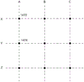
FIG. 13 illustrates an arrangement for monitoring changes in electrical impedance, according to some embodiments; and
14A-14E illustrate arrangements of traces for monitoring changes in electrical impedance, according to some embodiments.
15A-15B, 16A-16B, and 17A-17B illustrate a wound dressing implementing a sensor with an antenna according to some embodiments.
Detailed Description
Embodiments disclosed herein relate to apparatuses and methods for monitoring and treating biological tissue with a substrate implementing sensors. The embodiments disclosed herein are not limited to treating or monitoring a particular type of tissue or wound, and indeed, the techniques of implementing sensors disclosed herein are broadly applicable to any type of treatment that may benefit from a substrate implementing the sensors. Some embodiments utilize healthcare provider dependent sensors and data acquisition to make diagnoses and patient management decisions.
Some embodiments disclosed herein relate to the use of sensors mounted on or embedded within a substrate configured for treating intact and damaged human or animal tissue. Such sensors may collect information about surrounding tissue and transmit such information to a computing device or caregiver for further processing. In some embodiments, these sensors may be attached to the skin anywhere on the body, including areas that are monitored for arthritis, temperature, or other areas that may be prone to problems and require monitoring. The sensors disclosed herein may also incorporate markers, such as radiopaque markers, to indicate the presence of the device, for example, prior to performing MRI or other techniques.
The sensor embodiments disclosed herein may be used in conjunction with apparel. Non-limiting examples of apparel for use with embodiments of the sensors disclosed herein include shirts, pants, trousers, skirts, undergarments, gowns, gloves, shoes, hats, and other suitable clothing. In certain embodiments, the sensor embodiments disclosed herein may be welded into or laminated into and/or onto a particular garment. The sensor embodiments may be printed directly onto the garment and/or embedded into the fabric. Breathable and printable materials, such as microporous films, may also be suitable.
The sensor embodiments disclosed herein may be incorporated into cushions or mattresses, for example, within a hospital bed, to monitor patient characteristics, such as any of the characteristics disclosed herein. In certain embodiments, disposable membranes containing such sensors may be placed on hospital beds and removed/replaced as needed.
In some implementations, the sensor embodiments disclosed herein can incorporate energy harvesting such that the sensor embodiments are self-sustaining. For example, energy may be harvested from a thermal energy source, a kinetic energy source, a chemical gradient, or any suitable energy source.
The sensor embodiments disclosed herein may be used in rehabilitation devices and treatments, including sports medicine. For example, the sensor embodiments disclosed herein may be used with stents, sleeves, packaging materials, supports, and other suitable articles. Similarly, the sensor embodiments disclosed herein may be incorporated into sports equipment, such as helmets, sleeves, and/or pads. For example, such sensor embodiments may be incorporated into protective helmets to monitor characteristics such as acceleration, which may be used for concussion diagnostics.
The sensor embodiments disclosed herein may be used with a surgical device (e.g., the NAVIO surgical system of Smith & Nephew, inc.). In embodiments, sensor embodiments disclosed herein may communicate with such surgical devices to guide the placement of the surgical devices. In some embodiments, sensor embodiments disclosed herein can monitor blood flow to or from a potential surgical site or ensure that blood flow is not present at the surgical site. Additional surgical data may be acquired to help prevent scarring and to monitor areas away from the affected area.
To further assist in surgical techniques, the sensors disclosed herein may be incorporated into surgical drapes to provide information about the tissue under the drape that may not be immediately visible to the naked eye. For example, a sensor-embedded flexible drape may have sensors that are advantageously positioned to provide improved area-centric data acquisition. In certain embodiments, the sensor embodiments disclosed herein may be incorporated into the boundary or interior of a drape to create a fence to confine/control an operating room.
Sensor embodiments as disclosed herein may also be used for pre-operative evaluation. For example, such sensor embodiments may be used to gather information about potential surgical sites, for example, by monitoring the skin and underlying tissue for possible incision sites. For example, the perfusion level or other suitable characteristic may be monitored deeper into the skin surface and tissue to assess whether an individual patient is likely to be at risk for surgical complications. Sensor embodiments, such as those disclosed herein, can be used to assess the presence of a microbial infection and provide an indication of the use of an antimicrobial agent. In addition, the sensor embodiments disclosed herein may collect further information in deeper tissues, such as identifying pressure sore lesions and/or adipose tissue levels.
The sensor embodiments disclosed herein may be used for cardiovascular monitoring. For example, such sensor embodiments may be incorporated into a flexible cardiovascular monitor that may be placed against the skin to monitor characteristics of the cardiovascular system and communicate such information to another device and/or caregiver. For example, such devices may monitor pulse rate, blood oxygen, and/or electrical activity of the heart. Similarly, the sensor embodiments disclosed herein may be used in neurophysiological applications, such as monitoring electrical activity of neurons.
The sensor embodiments disclosed herein may be incorporated into implantable devices, such as implantable orthopedic implants, including flexible implants. Such sensor embodiments may be configured to gather information about the implant site and transmit that information to an external source. In some embodiments, an internal source may also provide power to this implant.
The sensor embodiments disclosed herein may also be used to monitor biochemical activity on or below the surface of the skin, such as lactose accumulation in muscle or sweat production on the surface of the skin. In some embodiments, other characteristics may be monitored, such as glucose concentration, urine concentration, tissue pressure, skin temperature, skin surface conductivity, skin surface resistivity, skin hydration, skin maceration, and/or skin dehiscence.
The sensor embodiments disclosed herein may be incorporated into an ear-nose-throat (ENT) application. For example, such sensor embodiments may be used to monitor recovery from ENT-related procedures, such as wound monitoring within the sinus tract.
As described in more detail below, the sensor embodiments disclosed herein may encompass sensor printing techniques with encapsulation, such as encapsulation with a polymer film. Such films may be constructed using any of the polymers described herein, such as polyurethane. The packaging of the sensor embodiments may provide water resistance of the electronics and protection of local tissue, local fluids, and other potential sources of damage.
In certain embodiments, the sensors disclosed herein may be incorporated into an organ protection layer, as disclosed below. The sensor-embedded organ protection layer can protect the organ of interest and confirm that the organ protection layer is in place and provide protection. Furthermore, the organ protection layer of the embedded sensor may be used to monitor the underlying organ, for example by monitoring blood flow, oxygenation and other suitable markers of organ health. In some embodiments, the organ protection layer implementing the sensor may be used to monitor the transplanted organ, for example, by monitoring the fat and muscle content of the organ. Furthermore, the organ may be monitored during and after transplantation (e.g., during recovery of the organ) using the organ protection layer implementing the sensor.
The sensor embodiments disclosed herein may be incorporated into a wound treatment (disclosed in more detail below) or a variety of other applications. Non-limiting examples of additional applications of the sensor embodiments disclosed herein include: monitoring and treatment of intact skin; cardiovascular applications, such as monitoring blood flow; orthopedic applications, such as monitoring limb movement and bone repair; neurophysiological applications, such as monitoring electrical impulses; and any other tissue, organ, system or condition that may benefit from improved monitoring of the implemented sensors.
Wound treatment
Some embodiments disclosed herein relate to wound therapy for the human or animal body. Thus, any reference herein to a wound may refer to a wound on a human or animal body, and any reference herein to a body may refer to a human or animal body. Embodiments of the disclosed technology may relate to preventing or minimizing damage to physiological or living tissue, or to treating wounds of damaged tissue (e.g., a wound as described herein) with or without reduced pressure, including, for example, negative pressure sources and wound dressing components and devices. Devices and components comprising the wound covering and filler material or inner layer (if present) are sometimes referred to herein collectively as dressings. In some embodiments, the wound dressing may be provided for use without reducing pressure.
Some embodiments disclosed herein relate to wound therapy for the human or animal body. Thus, any reference herein to a wound may refer to a wound on a human or animal body, and any reference herein to a body may refer to a human or animal body. Embodiments of the disclosed technology may relate to preventing or minimizing damage to physiological or living tissue, or to the treatment of damaged tissue (e.g., wounds as described herein).
As used herein, the expression "wound" may include damage to living tissue, typically skin that is incised or ruptured, that may be caused by cutting, pounding or other impact. The wound may be a chronic or acute injury. Acute wounds occur as a result of surgery or trauma. They undergo various stages of healing over the expected time frame. Chronic wounds usually begin with acute wounds. When an acute wound does not follow the healing phase, the acute wound may become a chronic wound, prolonging recovery time. The transition from acute to chronic wounds is thought to be due to immune impairment of the patient.
Chronic wounds may include, for example: venous ulcers (such as those occurring in the legs), which occupy most chronic wounds and affect mainly the elderly; diabetic ulcers (e.g., foot or ankle ulcers); peripheral arterial disease; pressure sores or Epidermolysis Bullosa (EB).
Examples of other wounds include, but are not limited to: abdominal or other large or incised wounds, dehiscent wounds, acute wounds, chronic wounds, subacute and dehiscent wounds, traumatic wounds, flaps and skin grafts, lacerations, abrasions, contusions, burns, diabetic ulcers, pressure sores, stomas, surgical wounds, trauma and venous ulcers and the like resulting from surgery, trauma, osteotomy, fasciotomy or other conditions.
Wounds may also include deep tissue damage. Deep tissue injury is a term proposed by the national pressure sore counseling group (NPUAP) to describe a unique form of pressure sore. Clinical physicians have for many years described these ulcers in terms such as purple pressure sores, ulcers that may worsen and bruise on bony elevations.
Wounds may also include tissue at risk of becoming a wound as discussed herein. For example, the tissue at risk may include tissue on bony prominences (with risk of deep tissue damage/injury) or pre-operative tissue (e.g., knee tissue) that may be cut (e.g., for joint replacement/surgical alteration/reconstruction).
Some embodiments relate to methods of treating wounds using the techniques disclosed herein in combination with one or more of the following: advanced footwear, turning patients, debridement (e.g., debridement of diabetic foot ulcers), treatment of infections, systemic fusion, antiseptics, antibiotics, surgery, removing tissue, affecting blood flow, physiological therapy, exercise, bathing, nutrition, hydration, nerve stimulation, ultrasound, electrical stimulation, oxygen therapy, microwave therapy, active agents ozone, antibiotics, antiseptics, and the like.
Alternatively or additionally, the wound may be treated with topical negative pressure and/or traditional advanced wound care, which is not assisted by the use of applied negative pressure (also referred to as non-negative pressure therapy).
Advanced wound care may include the use of absorbent dressings, occlusive dressings, the use of antimicrobial and/or debriding agents (e.g., cushioning or compression therapy such as stockings or bandages) in wound dressings or appendages, pads, and the like.
In some embodiments, these wounds may be treated using traditional wound care, where a dressing may be applied to the wound to facilitate and promote wound healing.
Some embodiments relate to a method of manufacturing a wound dressing, comprising providing a wound dressing as disclosed herein.
Wound dressings that can be used in conjunction with the disclosed techniques include any known in the art. The technique is applicable to negative pressure therapy treatment as well as non-negative pressure therapy treatment.
In some embodiments, the wound dressing includes one or more absorbent layers. The absorbent layer may be a foam or a superabsorbent.
In some embodiments, the wound dressing may include a dressing layer comprising a polysaccharide or modified polysaccharide, polyvinylpyrrolidone, polyvinyl alcohol, polyvinyl ether, polyurethane, polyacrylate, polyacrylamide, collagen, or a glue or a mixture thereof. Dressing layers comprising the listed polymers are known in the art as being useful for forming wound dressing layers for negative pressure therapy or non-negative pressure therapy.
In some embodiments, the polymer matrix may be a polysaccharide or a modified polysaccharide.
In some embodiments, the polymer matrix may be cellulose. The cellulosic material may comprise a hydrophilically modified cellulose, such as methyl cellulose, carboxymethyl cellulose (CMC), carboxymethyl cellulose (CEC), ethyl cellulose, propyl cellulose, hydroxyethyl cellulose, hydroxypropyl methyl cellulose, carboxyethyl cellulose sulfate, alkyl cellulose sulfonate, or mixtures thereof.
In certain embodiments, the cellulosic material may be a cellulose alkyl sulfonate. The alkyl moiety of the alkylsulfonate substituent may be an alkyl group having 1 to 6 carbon atoms, such as methyl, ethyl, propyl, or butyl. The alkyl moiety may be branched or unbranched and thus a suitable propyl sulphonate substituent may be 1-or 2-methyl-ethyl sulphonate. The butylsulfonate substituent may be 2-ethyl-ethanesulfonate, 2, 2-dimethyl-ethanesulfonate or 1, 2-dimethyl-ethanesulfonate. The alkyl sulfonate substituent may be ethyl sulfonate. Cellulose alkyl sulfonates are described in WO10061225, US2016/114074, US2006/0142560, or US5,703,225, the disclosures of which are incorporated herein by reference in their entirety.
The cellulose alkyl sulfonate may have varying degrees of substitution, chain length of the cellulose backbone structure, and structure of the alkyl sulfonate substituent. Solubility and absorption depend mainly on the degree of substitution: as the degree of substitution increases, the cellulose alkyl sulfonate becomes more and more soluble. It follows that as the solubility increases, the absorption increases.
In some embodiments, the wound dressing further comprises a top layer or cover layer.
The thickness of the wound dressing disclosed herein may be between 1mm and 20mm, or between 2mm and 10mm, or between 3mm and 7 mm.
In some embodiments, the disclosed techniques may be used in conjunction with non-negative pressure dressings. A non-negative pressure wound dressing suitable for providing protection at a wound site may comprise:
an absorbent layer for absorbing wound exudate; and
a masking element for at least partially masking the view of the absorbent layer absorbing wound exudate in use.
The shading element may be partially translucent.
The masking element may be a masking layer.
The non-negative pressure wound dressing may also include an area in or near the masking element to allow viewing of the absorbent layer. For example, the shading element layer may be disposed over a central region of the absorbing layer and not over a border region of the absorbing layer. In some embodiments, the masking element is or is coated with a hydrophilic material.
The shading elements may comprise a three-dimensional knitted spacer fabric. Spacer fabrics are known in the art and may include a knitted spacer fabric layer.
The shading element may also include an indicator to indicate that the dressing needs to be changed.
In some embodiments, the shield element is provided as a layer at least partially above the absorbent layer, in use being further away from the wound site than the absorbent layer.
The non-negative pressure wound dressing may also include a plurality of openings in the shield member to allow fluid to move therethrough. The masking element may comprise or be coated with a material having size exclusion properties for selectively allowing or preventing passage of molecules of a predetermined size or weight.
The shading elements may be configured to at least partially mask optical radiation having wavelengths of 600nm and less.
The shading elements may be configured to reduce light absorption by 50% or more.
The shading elements may be configured to produce CIE L values of 50 or more, and optionally 70 or more. In some embodiments, the shading elements may be configured to produce CIE L values of 70 or greater.
In some embodiments, the non-negative pressure wound dressing may further comprise at least one of a wound contact layer, a foam layer, an odor control element, a pressure resistant layer, and a cover layer.
In some embodiments, a cover layer is present, and the cover layer is a translucent film. Typically, the translucent film has a moisture vapor transmission rate of 500g/m2/24 hours or greater.
The translucent film may be a bacterial barrier.
In some embodiments, a non-negative pressure wound dressing as disclosed herein comprises a wound contact layer, and an absorbent layer overlies the wound contact layer. The wound contact layer carries an adhesive portion for forming a substantially fluid tight seal over the wound site.
A non-negative pressure wound dressing as disclosed herein may include a masking element and an absorbent layer provided as a single layer.
In some embodiments, the non-negative pressure wound dressings disclosed herein include a foam layer, and the material of the shielding element includes a component that may be displaced or damaged by movement of the shielding element.
In some embodiments, the non-negative pressure wound dressing includes an odor control element, and in another embodiment, the dressing does not include an odor control element. When present, the odor control element can be dispersed within or adjacent to the absorbent layer or the masking element. Alternatively, when present, the odour control element may be provided as a layer sandwiched between the foam layer and the absorbent layer.
In some embodiments, the disclosed techniques for non-negative pressure wound dressings include a method of manufacturing a wound dressing comprising: providing an absorbent layer for absorbing wound exudate; and providing a masking element for at least partially masking the view of wound exudate absorbed by the absorbent layer in use.
In some embodiments, a non-negative pressure wound dressing may be adapted to provide protection at a wound site, including: an absorbent layer for absorbing wound exudate; and a barrier layer disposed over the absorbent layer and further from the wound-facing side of the wound dressing than the absorbent layer. The shielding layer may be disposed directly over the absorbing layer. In some embodiments, the shielding layer comprises a three-dimensional spacer fabric layer.
The barrier layer increases the area of pressure transmission applied to the dressing by 25% or more or the initial area of application. For example, the barrier layer increases the area of transmission of pressure applied to the dressing by 50% or more, optionally 100% or more, or optionally 200% or more.
The shielding layer may include 2 or more sub-layers, wherein a first sub-layer includes vias and another sub-layer includes vias, and the vias of the first sub-layer are offset from the vias of the other sub-layer.
The non-negative pressure wound dressing as disclosed herein may further comprise a permeable cover layer for allowing gas and vapor to be transmitted therethrough, the cover layer being disposed over the barrier layer, wherein the through-holes of the cover layer are offset from the through-holes of the barrier layer.
Non-negative pressure wound dressings may be suitable for treating pressure sores.
A more detailed description of the non-negative pressure dressing disclosed above is provided in WO2013007973, the entire content of which is hereby incorporated by reference.
In some embodiments, the non-negative pressure wound dressing may be a multi-layer wound dressing comprising: a fibrous absorbent layer for absorbing exudate from the wound site; and a support layer configured to reduce shrinkage of at least a portion of the wound dressing.
In some embodiments, the multilayer wound dressings disclosed herein further comprise a liquid impermeable film layer, wherein the support layer is positioned between the absorbent layer and the film layer.
The support layer disclosed herein may comprise a mesh. The web may include a geometric structure having a plurality of generally geometric apertures extending therethrough. For example, the geometric structure may include a plurality of tabs that are substantially evenly spaced and joined by the polymeric strands to form generally geometric apertures between the polymeric strands.
The mesh may be formed of high density polyethylene.
The apertures may have an area of 0.005mm2 to 0.32mm 2.
The support layer may have a tensile strength of 0.05Nm to 0.06 Nm.
The support layer may have a thickness of 50 μm to 150 μm.
In some embodiments, the support layer is located immediately adjacent to the absorbent layer. Typically, the support layer is bonded to the fibers in the top surface of the absorbent layer. The support layer may further comprise a tie layer, wherein the support layer is thermally laminated to the fibers in the absorbent layer through the tie layer. The tie layer may comprise a low melting point adhesive, such as an ethylene vinyl acetate adhesive.
In some embodiments, the multilayer wound dressings disclosed herein further comprise an adhesive layer attaching the film layer to the support layer.
In some embodiments, the multilayer wound dressings disclosed herein further comprise a wound contact layer positioned adjacent the absorbent layer for positioning adjacent a wound. The multilayer wound dressing may further comprise a fluid transport layer between the wound contact layer and the absorbent layer for transporting exudate away from the wound into the absorbent layer.
A more detailed description of the multi-layer wound dressing disclosed above is provided in uk patent application no GB1618298.2 filed on 28/10/2016, the entire contents of which are hereby incorporated by reference.
In some embodiments, the disclosed techniques may be incorporated into a wound dressing comprising vertically overlapping materials, the wound dressing comprising: a first layer of absorbent material and a second layer of material, wherein the first layer is comprised of at least one layer of nonwoven textile fibers folded into multifolds to form a pleated structure. In some embodiments, the wound dressing further comprises a second layer of material that is temporarily or permanently attached to the first layer of material.
Typically, the vertically overlapping material has been cut.
In some embodiments, the first layer has a pleating structure with a depth determined by the pleat depth or by the cut width. The first layer material may be a moldable lightweight fiber-based material, a blend of materials, or a composite layer.
The first layer material may comprise one or more of fibres made from synthetic natural or inorganic polymers, natural fibres of cellulose, protein or mineral origin.
The wound dressing may include two or more absorbent layers of material stacked on top of another material, with the two or more layers having the same or different densities or compositions.
In some embodiments, the wound dressing may include only one layer of absorbent material of vertically overlapping material.
The layer of absorbent material is a blend of natural or synthetic, organic or inorganic fibers and binder fibers or bicomponent fibers, typically PET with a low melt temperature PET coating to soften at a specified temperature and act as a binder throughout the blend.
In some embodiments, the absorbent material layer may be a blend of 5% to 95% thermoplastic polymer, and 5% to 95% by weight cellulose or a derivative thereof.
In some embodiments, the wound dressings disclosed herein have a second layer comprising a foam or dressing fixture.
The foam may be a polyurethane foam. The polyurethane foam may have an open or closed cell structure.
The dressing fixture may include a bandage, tape, gauze, or backing layer.
In some embodiments, the wound dressings disclosed herein comprise a layer of absorbent material attached directly to a second layer by lamination or by an adhesive, and the second layer is attached to a dressing anchor layer. The adhesive may be an acrylic adhesive or a silicone adhesive.
In some embodiments, the wound dressings disclosed herein further comprise a layer of superabsorbent fibers, or a layer of viscose or polyester fibers.
In some embodiments, the wound dressing disclosed herein further comprises a backing layer. The backing layer may be a transparent or opaque film. Typically, the backing layer comprises a polyurethane film (typically a transparent polyurethane film).
A more detailed description of the multi-layer wound dressing disclosed above is provided in uk patent application No. GB1621057.7 filed on 12/2016 and uk patent application No. GB1709987.0 filed on 22/6/2017, the entire contents of which are hereby incorporated by reference.
In some embodiments, a non-negative pressure wound dressing may include an absorbent component for a wound dressing, the component including a wound contact layer comprising gel-forming fibers bonded to a foam layer, wherein the foam layer is directly bonded to the wound contact layer by an adhesive, a polymer-based melt layer, by flame lamination, or by ultrasound.
The absorbent member may be in the form of a sheet.
The wound contact layer may comprise a woven or non-woven or knitted gel-forming fibrous layer.
The foam layer may be an open cell foam or a closed cell foam, typically an open cell foam. The foam layer is a hydrophilic foam.
The wound dressing may include features that form islands in direct contact with the wound that is surrounded by the perimeter of the adhesive attaching the dressing to the wound. The adhesive may be a silicone or acrylic adhesive, typically a silicone adhesive.
The wound dressing may be covered by a film layer on the surface of the dressing furthest from the wound.
A more detailed description of a wound dressing of this type is provided above in EP2498829, the entire content of which is hereby incorporated by reference.
In some embodiments, a non-negative pressure wound dressing may include a multi-layered wound dressing for a wound that produces high levels of exudate, wherein the dressing comprises: a transmission layer having an MVTR of at least 300gm2/24 hours; an absorbent core comprising gel-forming fibers capable of absorbing and retaining exudates; a wound contact layer comprising gel-forming fibers that transport exudate to an absorbent core; and a bonding layer positioned on the absorbent core, the absorbent core and wound contact layer limiting lateral diffusion of exudate from the dressing to the wound area.
The wound dressing is capable of handling at least 6g (or 8g and 15g) of fluid per 10cm2 of the dressing in 24 hours.
The wound dressing may comprise gel-forming fibres, which are chemically modified cellulose fibres in the form of a fabric. The fibres may comprise carboxymethylated cellulosic fibres, typically sodium carboxymethylcellulose fibres.
The wound dressing may include a wound contact layer having a lateral wicking rate of 5 mm/min to 40 mm/min. The wound contact layer may have a fiber density of between 25gm2 and 55gm2, for example, 35gm 2.
The absorbent core may have an exudate absorbency of at least 10g/g, and typically has a lateral wicking rate of less than 20 mm/min.
The absorbent core may have a blend in the range of up to 25 wt% of cellulosic fibers and 75 wt% to 100 wt% of gel-forming fibers.
Alternatively, the absorbent core may have a blend in the range of up to 50 wt% of cellulose fibers and from 50 to 100 wt% of gel-forming fibers. For example, the blend is in the range of 50 wt% cellulosic fibers and 50 wt% gel-forming fibers.
The density of the fibers in the absorbent core may be between 150gm2 and 250gm2, or about 200gm 2.
The shrinkage of the wound dressing when wetted may be less than 25% or less than 15% of its original size/dimension.
The wound dressing may include a transmission layer, and the layer is a foam. The transfer layer may be a polyurethane foam laminated to a polyurethane film.
The wound dressing may comprise one or more layers selected from the group comprising a dissolvable drug film layer, an odour absorbing layer, a diffusion layer and an additional adhesive layer.
The wound dressing may be 2mm and 4mm thick.
The wound dressing may be characterized by a bonding layer bonding the absorbent core to an adjacent layer. In some embodiments, the bonding layer may be positioned on the wound-facing side of the absorbent core or the non-wound-facing side of the absorbent core. In some embodiments, the bonding layer is positioned between the absorbent core and the wound contact layer. The bonding layer is a polyamide web.
A more detailed description of a wound dressing of this type is provided above in EP1718257, the entire content of which is hereby incorporated by reference.
In some embodiments, the non-negative pressure wound dressing may be a compression bandage. Compression bandages are known for use in the treatment of, for example, edema of the lower extremities and other venous and lymphatic diseases.
Compression bandage systems typically employ multiple layers, including a backing layer between the skin and the compression layer or layers. Compression bandages may be used, for example, to treat wounds of venous leg ulcers.
In some embodiments, the compression bandage may include a bandage system including a skin-facing inner layer including a first foam layer and a second layer of an absorbent nonwoven web, and an elastic outer layer, the inner and outer layers being sufficiently elongated to be capable of being wrapped around a limb of a patient. Compression bandages of this type are disclosed in WO99/58090, the entire contents of which are hereby incorporated by reference.
In some embodiments, a compression bandage system comprises: a) an inner elongated skin-facing elastic bandage comprising: (i) an elongated resilient substrate, and
(ii) an elongate foam layer adhered to one face of the substrate and extending 33% or more across the face of the substrate in a transverse direction and 67% or more across the face of the substrate in a longitudinal direction; and b) an outer elongate self-adhesive elastic bandage having a compressive force when extended; wherein, in use, the foam layer of the inner bandage faces the skin and the outer bandage covers the inner bandage. Compression bandages of this type are disclosed in WO2006/110527, the entire content of which is hereby incorporated by reference.
In some embodiments, other compression bandage systems, such as those disclosed in US 6,759,566 and US 2002/0099318, the entire contents of which are hereby incorporated by reference.
Negative pressure wound dressing
In some embodiments, treatment of such wounds may be performed using negative pressure wound therapy, wherein reduced or negative pressure may be applied to the wound to facilitate and promote healing of the wound. It will also be appreciated that the wound dressings and methods as described herein may be applied to other parts of the body and are not necessarily limited to wound treatment.
It should be understood that embodiments of the present disclosure are generally applicable to topical negative pressure ("TNP") therapy systems. Briefly, negative pressure wound therapy helps to close and heal "difficult to heal" wounds of various morphologies by reducing tissue edema, promoting blood flow and granulation tissue formation, removing excess exudate, and may reduce bacterial load (thereby reducing infection risk). In addition, the therapy allows the wound to be less disturbed, resulting in faster healing. TNP therapy systems may also assist in the healing of surgically closed wounds by removing fluid and by helping to stabilize the tissue in close proximity to the closure site. Additional beneficial uses of TNP therapy may be found in grafts and flaps where removal of excess fluid is important and where close proximity of the graft to the tissue is required to ensure tissue viability.
Negative pressure therapy may be used to treat open or chronic wounds that are too large to spontaneously close or otherwise heal by applying negative pressure to the wound site. Topical Negative Pressure (TNP) therapy or Negative Pressure Wound Therapy (NPWT) involves placing a cover over the wound that is impermeable or semi-permeable to fluids, sealing the cover to the patient tissue surrounding the wound using various means, and connecting a source of negative pressure (such as a vacuum pump) to the cover in a manner that causes negative pressure to be created and maintained under the cover. It is believed that this negative pressure promotes wound healing by promoting the formation of granulation tissue at the wound site and assisting the body's normal inflammatory process while removing excess fluid that may contain adverse cytokines or bacteria.
Some of the dressings used in NPWT may include many different types of materials and layers, for example, gauze, pads, foam pads, or multi-layer wound dressings. One example of a multilayer wound dressing is the PICO dressing available from Smith & Nephew, which includes a wound contact layer and a superabsorbent layer beneath a backing layer to provide a can-less system for treating wounds with NPWT. The wound dressing may be sealed to a suction port that provides a connection to a length of tubing that may be used to pump fluid out of the dressing or to transfer negative pressure from the pump to the wound dressing. Additionally, RENASYS-F, RENASYS-G, RENASYS-AB and RENASYS-F/AB, available from Smith & Nephew, are additional examples of NPWT wound dressings and systems. Another example of a multilayer wound dressing is the ALLEVYN Life dressing available from Smith & Nephew, which includes a moist wound environment dressing for treating wounds without the use of negative pressure.
As used herein, a reduced or negative pressure level (such as-X mmHg) represents a pressure level relative to normal ambient atmospheric pressure, which may correspond to 760mmHg (or 1atm, 29.93inHg, 101.325kPa, 14.696psi, etc.). Therefore, the negative pressure value-X mmHg reflects an absolute pressure lower than 760mmHg by X mmHg, or in other words, reflects an absolute pressure (760-X) mmHg. Further, a negative pressure "lower" or "less" than X mmHg corresponds to a pressure closer to atmospheric pressure (e.g., -40mmHg is less than-60 mmHg). A negative pressure "higher" or "greater" than-X mmHg corresponds to a pressure further away from atmospheric pressure (e.g., -80mmHg is greater than-60 mmHg). In some embodiments, local ambient atmospheric pressure is used as a reference point, and such local atmospheric pressure may not necessarily be, for example, 760 mmHg.
The negative pressure range of some embodiments of the present disclosure may be about-80 mmHg, or between about-20 mmHg and-200 mmHg. It should be noted that these pressures are based on normal ambient atmospheric pressure (which may be 760 mmHg). Thus, in practice, -200mmHg would be about 560 mmHg. In some embodiments, the pressure range may be between about-40 mmHg and-150 mmHg. Alternatively, pressure ranges of up to-75 mmHg, up to-80 mmHg, or above-80 mmHg may be used. Additionally, in other embodiments, pressure ranges below-75 mmHg may be used. Alternatively, the negative pressure device may supply a pressure range in excess of about-100 mmHg, or even-150 mmHg.
In some embodiments of the wound closure devices described herein, increased wound contraction may result in increased tissue expansion in the surrounding wound tissue. This effect may be enhanced by varying the force applied to the tissue (e.g., by varying the negative pressure applied to the wound over time), possibly in combination with increased tension applied to the wound via embodiments of the wound closure device. In some embodiments, for example, the negative pressure may be varied over time using a sine wave, a square wave, or synchronized with one or more patient physiological indicators (e.g., heart beat). Examples of such applications in which additional disclosure related to the foregoing may be found include U.S. patent No. 8,235,955 entitled "round traffic apparatus and method" published on 8, 7, 2012; and U.S. patent No. 7,753,894 entitled "round cleaning apparatus with stress" published on 7/13/2010. The disclosures of both of these patents are hereby incorporated by reference in their entirety.
Embodiments of the wound dressings, wound dressing components, wound treatment apparatuses, and methods described herein may also be used in combination with or in addition to those described in the following documents: international application No. PCT/IB2013/001469 entitled "apparatus and method FOR NEGATIVE PRESSURE WOUND THERAPY (apparatus and method FOR NEGATIVE PRESSURE WOUND THERAPY)" filed on day 5, month 22, 2013 and published on day 11, month 28, 2013 and published as WO 2013/175306a 2; U.S. patent application No. 14/418,908 entitled "WOUND dressing and TREATMENT METHOD (WOUND DRESSING AND METHOD OF healing) filed on day 7, 9, 2015 at 1, 30, 2015 as published as US 2015/0190286a1, the disclosure OF which is hereby incorporated by reference in its entirety. Embodiments OF the WOUND dressing, WOUND dressing components, WOUND treatment apparatus and METHODs described herein may also be used in combination with or in addition to those described in U.S. patent application No. 13/092,042 entitled "WOUND dressing and METHOD OF USE" (WOUND DRESSING AND METHOD OF USE) filed on day 21/4/2011, and U.S. patent application No. 14/715,527 entitled "fluid CONNECTOR for negative PRESSURE WOUND THERAPY (fluent CONNECTOR for WOUND THERAPY) filed on 24/2016 a1 filed on 24/18/2016, the disclosure OF which is hereby incorporated herein by reference in its entirety, filed on 21/4/2011, including other details regarding WOUND dressings, WOUND dressing components and principles, and embodiments OF materials for WOUND dressings.
Furthermore, some embodiments of TNP wound treatment involving wound dressings that incorporate the pumps AND/or associated electronics described herein may also be used in combination with or in addition to those described in international application PCT/EP2016/059329 entitled "PRESSURE reduction APPARATUS AND method" (red PRESSURE APPARATUS AND METHODS), filed on 26/4/2016, published on 3/11/2016 in WO 2016/174048, the disclosure of which is hereby incorporated by reference in its entirety.
Wound monitoring and treatment system implementing sensors
Fig. 1A illustrates a wound monitoring and therapy system 10 according to some embodiments. The system includes a sensor-implemented wound dressing 22 connected to a controller 24. As described herein, the dressing 22 may be placed on or in a wound of a patient, and various sensors embedded or otherwise placed in the dressing 22 may be utilized to acquire measurement data from one or more of the wound or an area surrounding the wound (e.g., surrounding the wound). Controller 24 may receive, store, and process data collected by dressing 22. To facilitate communication, the dressing 22 may include one or more communication modules, such as one or more antennas as described herein. In some cases, the controller 24 can transmit one or more commands and data to the dressing 22.
In some embodiments, wound dressing 22 may be disposable and controller 24 may be reusable. In some embodiments, wound dressing 22 may be reusable. In some embodiments, wound dressing 22 may be sterilized or otherwise decontaminated or disinfected. In some embodiments, the controller 24 may be disposable. In some embodiments, the wound dressing 22 and the controller 24 may be permanently connected, and the combined wound dressing and control cassette is disposable, or reusable or re-sterilized or otherwise decontaminated or sterilized. Controller 24 may include a power source (e.g., a battery), one or more processors, one or more memory elements, and a communication device. In some embodiments, controller 24 may include one or more sensors, such as temperature sensors or optical sensors, to gather information about the patient or environmental conditions located remotely from the wound dressing. In some embodiments, the one or more sensors of controller 24 may include an accelerometer, a motion sensor, or a gyroscope. In some embodiments, wound dressing 22 may include one or more indicators that convey information to the user. The indicator may be visual, audible, tactile or tactile. The transmitted information may include measurement data, wound status, etc.
The computing device 40 may be configured to communicate with a remote computing device 50 that stores and processes medical data via a wired or wireless interface. In some embodiments, the remote computing device 50 may be a cloud computing device that includes one or more of remote memory, servers, processing devices, or any information storage devices. For example, the remote computing device 50 may process and store medical data according to one or more applicable security and privacy standards, such as the health insurance portability obligation act (HIPPA), european union data protection directives, and the like. The remote computing device 50 may make data provided by one or more of the computing device 40 or the mobile device 60 available for remote access and viewing, e.g., on the mobile device 60. In some embodiments, additional data may be added for storage on the remote computing device 50. For example, the mobile device 60 may add additional data through a dedicated application, a web browser interface, and so forth. The remote computing device 50 may process data from one or more of the wound dressing 22, the perfusion determination device 70, or the mobile device, and evaluate or determine a treatment plan, such as suggesting or adjusting one or more treatment therapies.
As described herein, the mobile device 60 may take one or more images of a wound of a patient. Such data may be transmitted to the remote computing device 50 via a wired or wireless interface. Although a smartphone is illustrated, the mobile device 60 may be any suitable computing device that includes imaging functionality, such as a camera. The mobile device 60 may also collect additional data, such as data entered by a healthcare provider in response to a questionnaire survey.
The various components illustrated in FIG. 1A are described in more detail in other portions of the disclosure.
Fig. 1B illustrates use of a wound monitoring and therapy system (e.g., system 10) according to some embodiments. As shown, in blocks 1101 and 1103, a user, such as a healthcare provider (HCP), may provide information about the patient's medical history and lifestyle. Such information may be provided by the mobile device 60 for storage on the remote computing device 50 as described herein (e.g., by an application). In block 1106, wound assessment may be performed. For example, the mobile device 60 may take an image of a wound and upload to the remote computing device 50 as described herein. Alternatively or additionally, the skin perfusion pressure may be measured by the device 70 and uploaded to the remote computing device 50 as described herein.
In block 1108, the user's treatment decision may be recorded. For example, one or more therapeutic therapies, such as negative pressure wound therapy, may be selected. In block 1110, additional images of the clean (if applicable) and debrided wound may be taken and uploaded to a remote computing device. In block 1112, the wound dressing 22 may be placed in or on a wound of a patient. In block 1114, where the wound dressing and the controller are separate, the controller 24 may be connected to the wound dressing 22. The wound dressing may be initialized as described herein. In block 1116, one or more selected therapies may be applied. In block 1118, an image of the wound covered by the wound dressing 22 may be captured and uploaded. In block 1120, measurement data from the wound dressing 22 may be collected and stored as described herein. This step may be performed a suitable number of times while the wound dressing 22 is applied to the patient. Upon completion of the treatment, in block 1122, the measurement data may be uploaded to the remote computing device 50 as described herein. In block 1124, an image of a healing wound may be taken.
In some embodiments, one or more images of a wound may be processed using the euler magnification techniques described in the following documents: international patent application No. PCT/EP2018/062207 entitled "new PRESSURE bearing boiler VIDEO mapping" filed on 11.5.2018, which claims priority from U.S. provisional patent application No. 62/506,524 entitled "new PRESSURE bearing THERAPY SYSTEM use bearing VIDEO mapping" filed on 15.5.2017; and international patent application No. PCT/EP2018/062206 entitled "WOUND ANALYSIS DEVICE AND METHOD" filed on 11.5.2018, which claims priority from U.S. provisional patent application No. 62/506,551 entitled "WOUND ANALYSIS DEVICEAND METHOD" filed on 15.5.15.2017, each of which is incorporated herein by reference in its entirety. Euler magnification techniques may be implemented by any component of system 10, such as mobile device 60 or remote computing device 50.
Wound dressing implementing a sensor
Fig. 1C illustrates a wound dressing 22 implementing a sensor according to some embodiments. As described herein, wound dressing 22 may include a substantially flexible substrate, which may include a wound contact layer having one or more features of any of the wound contact layers described herein. As used herein, "wound contact layer" may imply that the wound contact layer is with the substrate, and "substrate" may imply that both the substrate and the wound contact layer are together. The wound dressing 22 may include any of the wound dressing layers described herein. The entire wound dressing 22 may be substantially flexible. As shown, one or more sensors 26 connected by one or more electronic connections or traces 27 are positioned or embedded in wound dressing 22. In some embodiments, one or more sensors of wound dressing 22 may measure one or more of impedance, temperature, optical properties, and the like. In some embodiments, the one or more sensors of wound dressing 22 or any other wound dressing disclosed herein may measure one or more of the following: impedance, temperature, pH, pressure (e.g., by using strain gauges), tissue elasticity (e.g., by using ultrasonic sensors, piezoelectric transducers, etc.), blood flow (e.g., by measuring the doppler effect), color, or light. One or more of the sensors may be electronic or non-electronic. Examples of non-electronic sensors include sensors that change color as a function of pH or when stretched, strained, or otherwise subjected to pressure. Measurements of such sensors may be obtained by visual monitoring, which may be performed automatically, for example by using a camera or by using one or more optical sensors. One or more sensors and connections may be positioned on the wound contact layer. A connector 28 for connecting the wound dressing 22 to the controller 24 is also illustrated. The connector 28 includes one or more electrical connections or traces. In some embodiments, the boundary or edge of the wound contact layer may be smoothed by cutting, have a smooth contour, include fibers, and the like, to improve patient comfort.
In some embodiments, the dressing may contain one or more antennas for wireless communication. For example, one or more antennas may be printed as one or more connections or traces on the wound contact layer. In the absence of controller 24, one or more antennas may be used to transmit measurement data collected by one or more sensors. The one or more antennas may additionally be used to wirelessly receive power from a power source. In some cases, one or more antenna traces may be positioned on a substantially non-stretchable material (as described herein) such that the resonant frequency of the one or more antennas remains fixed when the wound dressing 22 is placed under stress while in use on a patient. For certain communication protocols, such as RFID, it may be advantageous to fix one or more resonant frequencies.
Negative pressure wound therapySystem for controlling a power supply
Fig. 2A illustrates one embodiment of a negative or reduced pressure wound therapy (or TNP) system 100 that includes a wound filler 130 disposed within a wound cavity 110 that is sealed by a wound cover 120. The wound filler 130 in combination with the wound cover 120 may be referred to as a wound dressing. The wound dressing may comprise one or more sensors as described herein. A single or multi-lumen tube or conduit 140 is connected to the wound cover 120, wherein the pump assembly 150 is configured to supply reduced pressure. The wound cover 120 may be in fluid communication with the wound cavity 110. In any of the system embodiments disclosed herein, as in the embodiment illustrated in fig. 2A, the pump assembly may be a canister-less pump assembly (meaning exudate is collected in the wound dressing or transferred via tubing 140 to be collected at another location). However, any of the pump assembly embodiments disclosed herein can be configured to include or support a canister. Additionally, in any of the system embodiments disclosed herein, any of the pump assembly embodiments can be mounted to or supported by or adjacent to the dressing.
The wound filler 130 may be of any suitable type, such as hydrophilic or hydrophobic foam, gauze, inflatable pouch, and the like. The wound filler 130 may conform to the wound cavity 110 such that it substantially fills the cavity. The wound cover 120 may provide a substantially fluid impermeable seal over the wound cavity 110. Wound cover 120 may have a top side and a bottom side, with the bottom side adhesively (or in any other suitable manner) sealed with wound cavity 110. The catheter 140 or lumen, or any other catheter or lumen disclosed herein, may be formed of polyurethane, PVC, nylon, polyethylene, silicone, or any other suitable material.
Some embodiments of wound cover 120 may have a port (not shown) configured to receive an end of conduit 140. For example, the Port may be a Renays Soft Port available from Smith & Nephew. In other embodiments, the conduit 140 may otherwise pass through or under the wound cover 120 to supply reduced pressure to the wound cavity 110 in order to maintain a desired reduced pressure level in the wound cavity. The conduit 140 may be any suitable article configured to provide an at least substantially sealed fluid flow path between the pump assembly 150 and the wound cover 120 for supplying reduced pressure provided by the pump assembly 150 to the wound cavity 110.
The wound cover 120 and wound filler 130 may be provided as a single article or in the form of a unitary, single unit. In some embodiments, no wound filler is provided, and the wound cover itself may be considered a wound dressing. The wound dressing may then be connected to a source of negative pressure, such as a pump assembly 150, via conduit 140. The pump assembly 150 can be miniaturized or portable, but larger conventional pumps can also be used.
Some embodiments of the system are designed to operate without the use of a bleed liquid tank. Some embodiments may be configured to support a bleed liquid tank. In some embodiments, configuring the pump assembly 150 and tubing 140 such that the tubing 140 can be quickly and easily removed from the pump assembly 150 can facilitate or improve the process of dressing or pump change (if needed). Any of the pump embodiments disclosed herein can be configured to have any suitable connection between the tubing and the pump.
In some embodiments, the pump assembly 150 can be configured to deliver a negative pressure of about-80 mmHg, or between about-20 mmHg and 200 mmHg. It should be noted that these pressures are relative to normal ambient atmospheric pressure, so-200 mmHg would actually be about 560 mmHg. The pressure may range from about-40 mmHg to-150 mmHg. Alternatively, pressure ranges of up to-75 mmHg, up to-80 mmHg, or above-80 mmHg may be used. Additionally, pressure ranges below-75 mmHg may be suitable. Alternatively, the pump assembly 150 can supply a pressure range in excess of about-100 mmHg or even 150 mmHg.
In operation, wound filler 130 is inserted into wound cavity 110 and wound cover 120 is placed to seal wound cavity 110. The pump assembly 150 provides a source of negative pressure to the wound cover 120 that is transmitted to the wound cavity 110 via the wound filler 130. Fluid (e.g., wound exudate) is drawn through the conduit 140 and may be stored in a canister. In some embodiments, the fluid is absorbed by the wound filler 130 or one or more absorbent layers (not shown).
Wound Dressings that may be used with the pump assemblies and other embodiments of the present application include Renasys-F, Renasys-G, Renasys AB, and Pico Dressings available from Smith & Nephew. Other descriptions of such wound dressings and other components of negative pressure wound therapy systems that may be used with pump assemblies and other embodiments of the present application may be found in U.S. patent publication nos. 2011/0213287, 2011/0282309, 2012/0116334, 2012/0136325, and 2013/0110058, which are incorporated herein by reference in their entirety. In other embodiments, other suitable wound dressings may be used.
Overview of wound dressing
Fig. 2B illustrates a cross-section through a wound dressing 155 according to some embodiments. Fig. 2B also illustrates a fluid connector 160 according to some embodiments. Wound dressing 155 may be similar to the wound dressing described in international patent publication WO2013175306a2, which is incorporated herein by reference in its entirety. Alternatively, wound dressing 155 may be any combination of features of any wound dressing embodiment disclosed herein or any number of wound dressing embodiments disclosed herein, which may be positioned over a wound site to be treated. Wound dressing 155 may be placed to form a sealed cavity over a wound, such as wound cavity 110. In some embodiments, wound dressing 155 includes a top layer or cover layer, or backing layer 220 attached to optional wound contact layer 222, both described in more detail below. The two layers 220, 222 are preferably joined or sealed together to define an interior space or chamber. The interior space or chamber may include additional structure that may be adapted to distribute or transmit negative pressure, store wound exudate and other fluids removed from the wound, as well as other functions, which will be explained in more detail below. Examples of such structures described below include the transmission layer 226 and the absorption layer 221.
As used herein, an upper, top or upper layer refers to the layer that is furthest from the skin or surface of the wound when the dressing is in use and positioned over the wound. Thus, a lower surface, layer, sub-layer or layer refers to the layer closest to the skin or surface of the wound when the dressing is in use and positioned over the wound.
The wound contact layer 222 may be a polyurethane or polyethylene layer or other flexible layer that is perforated, such as by a hot-pin process, a laser ablation process, an ultrasonic process, or in some other manner, or otherwise made permeable to liquids and gases. Wound contact layer 222 has a lower surface 224 (e.g., facing the wound) and an upper surface 223 (e.g., facing away from the wound). Perforations 225 preferably include through-holes in wound contact layer 222 that allow fluid to flow through layer 222. Wound contact layer 222 helps prevent tissue ingrowth into the other materials of the wound dressing. In some embodiments, the perforations are small enough to meet this requirement while still allowing fluid to flow therethrough. For example, perforations formed as slits or holes having a size in the range of 0.025mm to 1.2mm are considered to be small enough to help prevent tissue ingrowth into the wound dressing while allowing wound exudate to flow into the dressing. In some configurations, the wound contact layer 222 can help maintain the integrity of the entire dressing 155 while also creating an airtight seal around the absorbent pad to maintain negative pressure at the wound site. In some embodiments, the wound contact layer is configured to allow one-way or substantially one-way or one-way flow of fluid through the wound contact layer when negative pressure is applied to the wound. For example, the wound contact layer may allow fluid to flow through the wound contact layer away from the wound, but not allow fluid to flow back toward the wound. In some cases, the perforations in the wound contact layer are configured to allow such unidirectional or unidirectional fluid flow through the wound contact layer.
Some embodiments of wound contact layer 222 may also serve as a carrier for optional lower and upper adhesive layers (not shown). For example, the lower pressure sensitive adhesive may be provided on the lower surface 224 of the wound dressing 155 and the upper pressure sensitive adhesive layer may be provided on the upper surface 223 of the wound contact layer. The pressure sensitive adhesive may be a silicone, hot melt, hydrocolloid or acrylic based adhesive or other such adhesive, and may be formed on both sides of the wound contact layer, or alternatively on a selected one of the two sides of the wound contact layer, or not formed on both sides. The lower pressure sensitive adhesive layer, when used, can help adhere the wound dressing 155 to the skin surrounding the wound site. In some embodiments, the wound contact layer may comprise a perforated polyurethane film. The lower surface of the film may be provided with a silicone pressure sensitive adhesive and the upper surface may be provided with an acrylic pressure sensitive adhesive, which may help the dressing maintain its integrity. In some embodiments, the polyurethane film layer may be provided with adhesive layers on its upper and lower surfaces, and all three layers may be perforated together.
A layer of porous material 226 may be positioned over the wound contact layer 222. This porous or transmission layer 226 allows the transmission of fluids including liquids and gases away from the wound site into the upper layers of the wound dressing. In particular, the transmission layer 226 may ensure that the open air channels maintain a negative pressure delivered over the wound area even when the absorbent layer absorbs large amounts of exudate. The layer 226 may remain open under typical pressures applied during negative pressure wound therapy as described above, such that an equalized negative pressure is seen across the wound site. Layer 226 may be formed of a material having a three-dimensional structure. For example, a knitted or woven spacer fabric (e.g., Baltex 7970 weft knit polyester) or a non-woven fabric may be used.
In some embodiments, the transmission layer 226 comprises a 3D polyester spacer fabric layer comprising a top layer (i.e. the layer distal to the wound bed in use) of 84/144 textured polyester, and a bottom layer (i.e. the layer proximal to the wound bed in use) of 10 denier flat polyester, and a third layer formed sandwiched between the two layers, the third layer being an area defined by knitted polyester viscose, cellulose or similar monofilament fibres. Of course, other materials and other linear mass densities of fibers may be used.
Although reference is made throughout this disclosure to monofilament fibers, it should be understood that multiple strand alternatives may of course be used. Thus, the top spacer fabric has a greater number of filaments in the yarns used to form it than the number of filaments that make up the yarns used to form the bottom spacer fabric layer.
This difference between the number of filaments in the spaced apart layers helps to control the flow of moisture through the transfer layer. In particular, by having a greater number of filaments in the top layer, i.e., the top layer is made of yarns having more filaments than the yarns used for the bottom layer, liquid tends to wick more along the top layer than the bottom layer. In use, this difference tends to wick liquid away from the wound bed and into the central region of the dressing where the absorbent layer 221 helps to lock the liquid out or wick the liquid forward on itself toward the liquid-transpirable cover layer.
In some embodiments, to improve the flow of liquid through the transmission layer 226 (that is, perpendicular to the channel region formed between the top and bottom spacer layers), the 3D fabric may be treated with a dry cleaning agent (e.g., without limitation, perchloroethylene) to help remove any manufactured products, such as previously used mineral oils, fats, or waxes, that may interfere with the hydrophilic ability of the transmission layer. Subsequently, an additional manufacturing step may be performed in which the 3D spacer fabric is washed in a hydrophilic agent (such as, but not limited to, Feran Ice 30g/l available from Rudolph Group). This process step helps to ensure that the surface tension on the material is very low so that liquids such as water can enter the 3D knitted fabric once they contact the fabric. This also helps to control the flow of the liquid fouling component of any exudate.
The absorbing material layer 221 may be disposed over the transmission layer 226. An absorbent material comprising foam or a non-woven natural or synthetic material, and optionally a superabsorbent material, forms a reservoir for fluid (particularly liquid) to be removed from the wound site. In some embodiments, layer 221 may also help absorb fluids toward backing layer 220.
The material of the absorbent layer 221 may also prevent liquids collected in the wound dressing 155 from freely flowing within the dressing, and may serve to contain any liquids collected within the dressing. The absorbent layer 221 also helps distribute fluid throughout the layer via wicking for fluid absorption from the wound site and storage throughout the absorbent layer. This helps to prevent accumulation in the area of the absorbent layer. The capacity of the absorbent material must be sufficient to manage the exudate flow rate of the wound when negative pressure is applied. Since, in use, the absorbent layer is subjected to a negative pressure, the material of the absorbent layer is selected to absorb liquid in this case. There are many materials, such as superabsorbent materials, that are capable of absorbing liquid under negative pressure. The absorption layer 221 may be generally composed of ALLEVYNTMFoam, Freudenberg 114-TM11C-450. In some embodiments, the absorbent layer 221 can include a composite material including superabsorbent powder, a fibrous material, such as cellulose, and binding fibers. In some embodiments, the composite is an airlaid thermal bond composite.
In some embodiments, the absorbent layer 221 is a nonwoven cellulosic fiber layer having superabsorbent material in the form of dry particles dispersed throughout. The use of cellulose fibers introduces a fast wicking element that helps to rapidly and uniformly distribute the liquid absorbed by the dressing. The juxtaposition of the multi-strand fibers results in a strong capillary action in the fiber mat, which helps to distribute the liquid. In this way, the superabsorbent material is effectively supplied with liquid. Wicking also helps to bring liquid into contact with the overlying layer to help increase the transpiration rate of the dressing.
An orifice, hole, or aperture 227 may be provided in the backing layer 220 to allow negative pressure to be applied to the dressing 155. In some embodiments, the fluid connector 160 is attached or sealed to the top of the backing layer 220 over the aperture 227 created in the dressing 155 and transmits negative pressure through the aperture 227. A length of tubing may be coupled at a first end to fluid connector 160 and at a second end to a pump unit (not shown) to allow fluid to be pumped out of the dressing. Where the fluid connector is adhered to the top layer of the wound dressing, a length of tubing may be coupled at the first end of the fluid connector such that the tubing or conduit extends parallel or substantially to the top surface of the dressing away from the fluid connector. The fluid connector 160 may be adhered and sealed to the backing layer 220 using an adhesive, such as acrylic, cyanoacrylate, epoxy, UV curable, or hot melt adhesive. The fluid connector 160 may be formed from a soft polymer, such as polyethylene, polyvinyl chloride, silicone, or polyurethane, having a shore a durometer of 30 to 90. In some embodiments, the fluid connector 160 may be made of a soft or conformable material.
In some embodiments, the absorbent layer 221 includes at least one through-hole 228 positioned so as to be located below the fluid connector 160. In some embodiments, the through-hole 228 may be the same size as the opening 227 in the backing layer, or may be larger or smaller. As shown in fig. 2B, a single through-hole may be used to create an opening located below fluid connector 160. It will be appreciated that a plurality of openings may alternatively be used. Additionally, if more than one port is used according to certain embodiments of the present disclosure, one or more openings may be created in the absorbent layer and the obscuring layer in registration with each respective fluid connector. Although not necessary for certain embodiments of the present disclosure, the use of through-holes in the superabsorbent layer can provide fluid flow paths that remain unobstructed, particularly when the absorbent layer is near saturation.
As shown in fig. 2B, an aperture or via 228 may be provided in the absorber layer 221 below the aperture 227, such that the aperture is directly connected to the transmission layer 226. This allows the negative pressure applied to the fluid connector 160 to communicate with the transmission layer 226 without passing through the absorbent layer 221. This ensures that the negative pressure applied to the wound site is not inhibited by the absorbent layer when it absorbs wound exudate. In other embodiments, no openings may be provided in the absorber layer 221, or alternatively, a plurality of openings may be provided below the aperture 227. In other alternative embodiments, additional layers (e.g., another transmission layer or a masking layer as described in international patent publication WO2014020440, which is incorporated herein by reference in its entirety) may be provided above the absorbent layer 221 and below the backing layer 220.
The backing layer 220 may be air impermeable, but permeable to water vapor, and may extend across the width of the wound dressing 155. The backing layer 220, which may be, for example, a polyurethane film (e.g., Elastollan SP9109) having a pressure sensitive adhesive on one side, is gas impermeable, and this layer thus serves to cover the wound and seal the wound cavity on which the wound dressing is placed. In this way, an effective chamber is created between the backing layer 220 and the wound site, in which chamber a negative pressure can be created. For example, the backing layer 220 may be sealed to the wound contact layer 222 in a border area around the circumference of the dressing by adhesive or welding techniques, ensuring that no air is drawn through the border area. The backing layer 220 protects the wound from external bacterial contamination (bacterial barrier) and allows liquid from wound exudate to be transported through this layer and evaporate from the outer surface of the film. The backing layer 220 may include two layers: a polyurethane film and an adhesive pattern coated on the film. The polyurethane film is permeable to moisture and may be made of a material that has an increased permeability to water when wetted. In some embodiments, the moisture permeability of the backing layer increases when the backing layer becomes wet. The water vapor permeability of the wet back liner may be up to about ten times greater than the water vapor permeability of the dry back liner.
The area of the absorbent layer 221 may be larger than the area of the transmission layer 226 so that the absorbent layer overlaps the edges of the transmission layer 226, thereby ensuring that the transmission layer does not contact the backing layer 220. This provides an outer channel of the absorbent layer 221 which is in direct contact with the wound contact layer 222, which facilitates a faster absorption of exudate to the absorbent layer. Furthermore, the further channels ensure that no liquid can collect around the perimeter of the wound cavity, which might otherwise penetrate through the seal around the perimeter of the dressing, resulting in the formation of leaks. As shown in fig. 2B, the absorbent layer 221 may define a perimeter that is smaller than the backing layer 220 such that a demarcation or border region is defined between an edge of the absorbent layer 221 and an edge of the backing layer 220.
As shown in fig. 2B, one embodiment of the wound dressing 155 includes an aperture 228 in the absorbent layer 221 below the fluid connector 160. In use, for example when negative pressure is applied to the dressing 155, the wound-facing portion of the fluid connector may thus be in contact with the transmission layer 226, which may thus facilitate transmission of negative pressure to the wound site even when the absorbent layer 221 is filled with wound fluid. Some embodiments may have the backing layer 220 at least partially adhered to the transmission layer 226. In some embodiments, the aperture 228 is at least 1-2mm larger than the diameter of the wound facing portion or aperture 227 of the fluid connector 11.
For example, in embodiments having a single fluid connector 160 and through-hole, it may be preferable for the fluid connector 160 and through-hole to be located in an off-center position. Such a position may allow the dressing 155 to be positioned on the patient such that the fluid connector 160 is elevated relative to the remainder of the dressing 155. So positioned, the fluid connector 160 and filter 214 are less likely to come into contact with wound fluid that may prematurely occlude the filter 214, such that transmission of negative pressure to the wound site is impaired.
Turning now to fluid connector 160, some embodiments include a sealing surface 216, a bridge 211 having a proximal end (closer to the negative pressure source) and a distal end 140, and a filter 214. The sealing surface 216 may form an applicator that is sealed to the top surface of the wound dressing. In some embodiments, the bottom layer of the fluid connector 160 may include a sealing surface 216. The fluid connector 160 may also include an upper surface vertically spaced from the sealing surface 216, which in some embodiments is defined by a separate upper layer of the fluid connector. In other embodiments, the upper and lower surfaces may be formed from the same piece of material. In some embodiments, the sealing surface 216 may include at least one aperture 229 therein to communicate with the wound dressing. In some embodiments, the filter 214 may be positioned through the opening 229 in the sealing surface, and may span the entire opening 229. Sealing surface 216 may be configured to seal the fluid connector to a cover layer of a wound dressing and may include an adhesive or a weld. In some embodiments, the sealing surface 216 may be placed over an aperture in the cover layer, with an optional spacer element 215 configured to create a gap between the filter 214 and the transmission layer 226. In other embodiments, the sealing surface 216 may be positioned over apertures in the cover layer and apertures in the absorbent layer 220 to allow the fluid connector 160 to provide air flow through the transmission layer 226. In some embodiments, the bridge 211 can include a first fluid passage 212 in communication with a negative pressure source, the first fluid passage 212 including a porous material, e.g., a 3D knitted material, which can be the same as or different from the porous layer 226 described previously. The bridge 211 may be enclosed by at least one flexible membrane layer 208, 210 having a proximal end and a distal end, and configured to surround a first fluid pathway 212, the distal end of the flexible membrane connecting a sealing surface 216. The filter 214 is configured to substantially prevent wound exudate from entering the bridge, and the spacing element 215 is configured to prevent the fluid connector from contacting the transmission layer 226. These elements will be described in more detail below.
Some embodiments may also include an optional second fluid passageway positioned above the first fluid passageway 212. For example, some embodiments may provide air leakage that may be disposed at a proximal end of a top layer configured to provide an air path into the first fluid pathway 212 and the dressing 155, similar to the suction adapter described in U.S. patent No. 8,801,685, which is incorporated herein by reference in its entirety.
In some embodiments, the fluid pathways 212 are constructed of a compliant material that is flexible and also allows fluid to pass therethrough if the spacers kink or fold. Suitable materials for the fluid pathway 212 include, without limitation, foams, including open foams, such as polyethylene or polyurethane foams, meshes, 3D knitted fabrics, nonwovens, and fluid channels. In some embodiments, the fluid passage 212 may be constructed of materials similar to those described above with respect to the transmission layer 226. Advantageously, such materials used in the fluid pathway 212 not only allow for greater patient comfort, but also provide greater kink resistance so that the fluid pathway 212 is still able to transport fluid from the wound toward the negative pressure source when kinked or bent.
In some embodimentsIn (e.g., the fluid channel 212) may be formed of a wicking fabric, such as a knitted or woven spacer fabric (e.g., knitted polyester 3D fabric, Baltex @) Or Gehring
 ) Or a nonwoven fabric. These materials selected may be suitable for channeling wound exudate away from the wound through the channels and for delivering negative pressure or exhaust air to the wound site, and may also impart a degree of kink or occlusion resistance to the
 fluid pathway 212. In some embodiments, the wicking fabric may have a three-dimensional structure, which in some cases may help wick fluid or transmit negative pressure. In certain embodiments including wicking fabrics, these materials remain open and are capable of transmitting negative pressure to the wound area at pressures typical for use in negative pressure therapy (e.g., -40 to-150 mmHg). In some embodiments, the wicking fabric may comprise several layers of material stacked or laminated on one another, which may be used in some cases to prevent the fluid pathway 212 from collapsing under the application of negative pressure. In other embodiments, the wicking fabric used in the fluid pathway 212 may be between 1.5mm to 6 mm; more preferably, the wicking fabric may be 3mm to 6mm thick and may comprise one or several separate layers of wicking fabric. In other embodiments, the fluid passageway 212 may be 1.2-3mm thick, and preferably thicker than 1.5 mm. Some embodiments (e.g., a suction adapter for a dressing holding a liquid such as wound exudate) may use a hydrophobic layer in the fluid pathway 212, and only gas may travel through the fluid pathway 212. Furthermore, and as previously mentioned, the materials used in the system may be conformable and soft, which may help avoid pressure sores and other complications that may be caused by the wound treatment system pressing against the patient's skin.
In some embodiments, the filter element 214 is liquid impermeable, but gas permeable, and is provided to act as a liquid barrier and ensure that no liquid is able to escape from the wound dressing 155. The filter element 214 may also act as a bacterial barrier. Typically, the pore size is 0.2 μm. For filter elements 214Suitable materials for the filter material include 0.2 micron Gore from the MMT seriesTMExpanded PTFE, PALL VersaporeTM200R and DonaldsonTMTX 6628. Larger pore sizes may also be used, but these may require a secondary filtration layer to ensure complete bioburden containment. Since the wound fluid contains liquid, it is preferred, but not necessary, to use an oleophobic filter membrane, e.g., 1.0 micron MMT-332, before 0.2 micron MMT-323. This prevents the lipid from clogging the hydrophobic filter. The filter element may be attached or sealed to the cover membrane over the port or aperture. For example, the filter element 214 may be molded into the fluid connector 160, or may be adhered to one or both of the top of the cover layer and the bottom of the suction adapter 160 using an adhesive (such as, but not limited to, a UV cured adhesive).
It should be understood that other types of materials may be used for the filter element 214. More generally, microporous films, which are thin flat sheets of polymeric material containing billions of micropores, can be used. Depending on the membrane selected, these pores may range in size from 0.01 to greater than 10 microns. Microporous membranes have both hydrophilic (drainage) and hydrophobic (waterproofing) forms. In some embodiments, the filter element 214 includes a support layer and an acrylic copolymer membrane sheet formed on the support layer. In some embodiments, wound dressing 155 according to certain embodiments uses a Microporous Hydrophobic Membrane (MHM). Many polymers can be used to form MHMs. For example, the MHM may be formed from one or more of PTFE, polypropylene, PVDF, and acrylic copolymers. All of these optional polymers may be treated to obtain specific surface characteristics that may be hydrophobic and oleophobic. Thus, these will reject liquids with low surface tension, such as multi-vitamin infusions, lipids, surfactants, oils and organic solvents.
The MHM blocks liquid while allowing air to flow through the membrane. They are also highly efficient air filters that eliminate potentially infectious aerosols or particles. It is well known that a single piece MHM is an alternative to mechanical valves or vents. Accordingly, configuring the MHM may reduce product assembly costs to improve patient profits and cost/benefit ratios.
The filter element 214 may also include an odor absorbing material such as activated carbon, carbon fiber cloth, or Vitech Carbotec-RT Q2003073 foam, among others. For example, the odor absorbing material may form a layer of the filter element 214, or may be sandwiched between microporous hydrophobic membranes of the filter element. The filter element 214 thus allows gas to vent through the pores. However, the dressing contains liquids, particles and pathogens.
Wound dressing 155 may include a spacer element 215 in combination with fluid connector 160 and filter 214. By adding this spacing element 215, the fluid connector 160 and filter 214 may be supported without direct contact with the absorbent layer 220 or transmission layer 226. The absorptive layer 220 may also serve as an additional spacing element to keep the filter 214 from contacting the transmission layer 226. Thus, with this configuration, contact of the filter 214 with the transmission layer 226 and wound fluid during use may therefore be minimized.
Similar to the embodiments of wound dressings described above, some wound dressings include a perforated wound contact layer having a silicone adhesive on the wound or skin-contacting side and/or an acrylic adhesive on the back side. The wound contact layer may be perforated to match any pattern suitable for a particular wound. A transmission layer or 3D spacer fabric mat is located above the boundary layer. The absorption layer is located above the transmission layer. The absorbent layer may comprise a superabsorbent Nonwoven (NW) mat. The absorbent layer may be about 5mm across the transmission layer at the perimeter. The absorbent layer may have an opening or through hole towards one end. The opening may be about 10mm in diameter. The backing layer is positioned over the transmission layer and the absorbent layer. The backing layer may be a high Moisture Vapor Transmission Rate (MVTR) film coated with a pattern of acrylic adhesive. The high MVTR film and wound contact layer encapsulate the transmission layer and the absorbent layer, creating a peripheral boundary of about 20 mm. The backing layer may have 10mm openings overlying the openings in the absorbent layer. A fluid connector may be attached over the aperture, the fluid connector including a liquid impermeable, gas permeable semi-permeable membrane (SPM) overlying the aperture.
Wound dressing with sensor
As described herein, a wound dressing comprising a plurality of sensors may be utilized in order to monitor characteristics of a wound as the wound heals. Collecting data from well-healed as well as non-well-healed wounds may provide useful insight to identify the measured object to indicate whether the wound is on a healing or non-healing trajectory. Any of the disclosed wound dressings, such as wound dressing 22, may include one or more of the following features or any other features disclosed herein.
In some embodiments, a number of sensor technologies may be used for the wound dressing or one or more components forming part of the overall wound dressing apparatus. For example, as shown in fig. 3 and 4D, which describe wound dressings 250, 320 having an array of sensors according to some embodiments, one or more sensors may be incorporated onto or into a wound contact layer, which may be a perforated wound contact layer, as shown in fig. 4D. In some embodiments, as illustrated in fig. 3, wound dressing 250 may include a temperature sensor 252, a conductivity sensor 254, an optical sensor 256, and/or an SpO2 sensor 258. The wound contact layer in fig. 3 and 4D is shown as having a square shape, but it will be appreciated that the wound contact layer may have other shapes, such as rectangular, circular, oval, and the like. In some embodiments, the sensor-integrated wound contact layer may be provided as a separate layer of material that is placed over the wound area and then covered by the wound dressing device or a component of the wound dressing device, e.g., gauze, foam or other wound packing material, a super-absorbent layer, a drape, a fully integrated dressing such as a Pico or Allevyn Life dressing, or the like. In other embodiments, the sensor-integrated wound contact layer may be part of a single unit dressing such as described herein.
The sensor-integrated wound contact layer may be placed in contact with the wound and will allow fluid to pass through the contact layer while causing little or no damage to the tissue in the wound. The sensor-integrated wound contact layer may be made of a flexible material such as silicone and may contain antimicrobial agents or other therapeutic agents known in the art. In some embodiments, the sensor-integrated wound contact layer may comprise an adhesive that adheres to wet or dry tissue. In some embodiments, the sensor or sensor array may be incorporated into or encapsulated in other components of the wound dressing (e.g., the absorbent or spacer layer described above).
As shown in FIGS. 3 and 4D, five sensors may be used, including, for example, sensors for temperature (e.g., 25 thermistor sensors in a 5 × array at 20mm spacing), oxygen saturation or SpO2 (e.g., 4 or 5 SpO2 sensors in a single line from the center of the wound contact layer to its edge at 10mm spacing), tissue color (e.g., 10 optical sensors in a2 × array at 20mm spacing; not all 5 sensors in each row of the array need to be aligned), pH (e.g., by measuring the color of the pH sensitive pad, optionally using the same optical sensor as the tissue color), and conductivity (e.g., 9 conductive contacts in a 3 × array at 40mm spacing.) As shown in FIG. 4A, SpO2 sensors may be arranged in a single column from the center or near the center of the wound contact layer to the edge of the wound contact layer.
The sensor may be bonded to a flexible circuit board formed of flexible polymers including polyamides, Polyimides (PI), polyesters, polyethylene naphthalate (PEN), Polyetherimides (PEI), along with various Fluoropolymers (FEP) and copolymers, or any material known in the art. The sensor array may be incorporated into a two-layer flex circuit. In some embodiments, the circuit board may be a multilayer flexible printed circuit. In some embodiments, these flexible circuits may be incorporated into any layer of the wound dressing. In some embodiments, the flexible circuit may be incorporated into the wound contact layer. For example, the flexible circuit may be incorporated into a wound contact layer similar to that described with reference to fig. 2B. The wound contact layer may have cuts or slits that allow one or more sensors to protrude from the lower surface of the wound contact layer and directly contact the wound area.
In some embodiments, the sensor-integrated wound contact layer may include first and second wound contact layers with the flexible circuit board sandwiched between the two layers of wound contact layer material. The first wound contact layer has a lower surface intended to be in contact with a wound and an upper surface intended to be in contact with a flexible circuit board. The second wound contact layer has a lower surface intended to be in contact with the flexible circuit board and an upper surface intended to be in contact with the wound dressing or one or more components forming part of the overall wound dressing apparatus. The upper surface of the first wound contact layer and the lower surface of the second wound contact layer may be adhered together by a flexible circuit board sandwiched between the two layers.
In some embodiments, the one or more sensors of the flexible circuit board may be completely encapsulated or covered by the wound contact layer to prevent contact with moisture or fluids in the wound. In some embodiments, the first wound contact layer may have a cut or slit that allows the one or more sensors to protrude from the lower surface and directly contact the wound area. For example, one or more SpO2 sensors as shown in fig. 4D are shown protruding from the bottom surface of the wound contact layer. In some embodiments, the SpO2 sensor may be mounted directly on the lower surface of the first wound contact layer. Some or all of the sensors and electrical or electronic components may be potted or encapsulated (e.g., rendered waterproof or liquidproof) with a polymer (e.g., a silicon or epoxy-based polymer). Encapsulation with a polymer can prevent fluid ingress and leaching of chemicals from the component. In some embodiments, the wound contact layer material may seal the component to prevent water from entering and leaching out chemicals.
In some embodiments, collecting and processing information related to a wound may use three components, including a sensor array, a control or processing module, and software. These components are described in more detail herein.
Fig. 4A illustrates a flexible sensor array circuit board 300 including a sensor array portion 301, a tail portion 302, and a connector pad end portion 303, according to some embodiments. Sensor array portion 301 may include sensors and associated circuitry. Sensor array circuit board 300 may include a long tail 302 extending from a sensor array portion 301. The connector pad end 303 can be connected to a control module or other processing unit to receive data from the sensor array circuitry. The long tail 302 may allow the control module to be placed away from the wound, e.g., in a more convenient location away from the wound.
FIG. 4B illustrates an embodiment of a flexible circuit board having four different sensor array geometries 301A, 301B, 301C, and 301D. The illustrated embodiment includes tails 302A, 302B, 302C, and 302D. In some embodiments, the flexible circuit board includes a short portion or no tail portion. In some embodiments, the four different sensor array geometries shown may be implemented in a flex circuit. Although FIG. 4B shows four different sensor array formats and configurations, designs 301B and 302B also include connector pad ends 303 configured to provide electrical or electronic connections between the initiator array 301B and the control module. One or more of the designs 301A, 301C, or 301D may also include connector pad ends, such as portion 303, to allow the flexible circuit board 301A, 301C, or 301D to communicate with a control module or other processing unit. In some embodiments, the sensor array communicates wirelessly with the control module, and the tail may be omitted.
FIG. 4C shows sensor array portion 301B of the sensor array design of FIG. 4B in more detail. In any one or more of the embodiments of fig. 3 or fig. 4A-4D, the sensor array portion may include a plurality of portions that extend around the perimeter of the wound dressing member (e.g., wound contact layer) or inward from the outer edge of the wound dressing member. For example, the illustrated embodiment includes a plurality of linearly extending portions that may be parallel to the edges of the wound dressing member and, in some embodiments, follow the entire perimeter of the wound dressing member. In some embodiments, the sensor array portion may include a first plurality of parallel linear extensions that are perpendicular to a second plurality of parallel linear extensions. These linear extensions may also be of different lengths and may extend inwardly to different locations within the wound dressing member. The sensor array portion preferably does not cover the entire wound dressing member, thereby forming a gap between portions of the sensor array. This allows some, and possibly most, of the wound dressing components to be uncovered by the sensor array, as shown in fig. 3. For example, for a perforated wound contact layer as shown in fig. 3 and 4D, the sensor array portion 301 may not block most of the perforations in the wound contact layer. In some embodiments, the sensor array may also be perforated or shaped to match perforations in the wound contact layer, thereby minimizing the resistance of the perforations to fluid flow.
Fig. 4D illustrates a flexible sensor array incorporated into a perforated wound contact layer 320 according to some embodiments. As shown, the sensor array may be sandwiched between two membranes or wound contact layers. The wound contact layer may have perforations formed as slits or holes as described herein that are small enough to help prevent tissue ingrowth into the wound dressing while allowing wound exudate to flow into the dressing. In some embodiments, the wound contact layer may have one or more slits that increase the flexibility of the wound contact layer with the integrated sensor array. In some embodiments, one of the wound contact layers may have additional cutouts to accommodate sensors so that they may directly contact the skin.
The connections of the sensor array may vary depending on the various sensors and sensor array designs used. In some embodiments, for example, as shown in fig. 4B, a total of 79 connections may be used to connect the components of the sensor array. The sensor array may terminate in two parallel 40-way 0.5mm pitch Flat Flex Cable (FFC) contact surfaces with terminals on the top surface designed to connect to FFC connectors such as Molex 54104-.
In some embodiments, one or more of the sensors (such as a thermistor, conductivity sensor, SpO2 sensor, color sensor, etc.) may be used on the sensor array to provide information related to the wound and/or the state surrounding the wound. Any of the sensor arrays and/or single sensors disclosed herein can assist a clinician in monitoring the status of a wound, which can include wound healing or non-healing (e.g., stable, worsening, etc.) of the wound. One or more sensors may operate individually or in coordination with one another to provide data relating to the wound and wound healing characteristics.
The temperature sensor may use a thermocouple or a thermistor to measure the temperature. The thermistor may be used to measure or track the temperature of the underlying wound or the thermal environment within the wound dressing. The thermometric sensors may be calibrated, and data obtained from the sensors may be processed to provide information about the wound environment. In some embodiments, an ambient sensor that measures the ambient air temperature may also be used to help eliminate problems associated with ambient temperature excursions.
Optical sensors can be used to measure wound appearance using RGB sensors with illumination sources. In some embodiments, both the RGB sensor and the illumination source may be pressed against the skin such that the light will penetrate into the tissue and present the spectral characteristics of the tissue itself.
Light propagation in tissue can be dominated by two main phenomena (scattering and attenuation). For attenuation, as light passes through tissue, its intensity may be lost due to absorption by various components of the tissue. Blue light tends to be severely attenuated, while light at the red end of the spectrum tends to be minimally attenuated.
The scattering process may be more complex and may have various "regions" (regions) that must be considered. A first aspect of scattering is based on a comparison of the size of the scattering center with the wavelength of the incident light. If the scattering center is much smaller than the wavelength of light, Rayleigh (Rayleigh) scattering can be assumed. If the scattering center is around the wavelength of light, then a more detailed Mie scattering formula must be considered. Another factor involved in scattering light is the distance between the input and output of the scattering medium. Ballistic photon transmission is assumed if the mean free path of light (the distance between scattering events) is much greater than the distance traveled. In the case of tissue, the scattering events are about 100 microns apart, so a path distance of 1mm will effectively randomize the photon direction and the system will enter the diffuse region.
Ultra bright Light Emitting Diodes (LEDs), RGB sensors and polyester optical filters can be used as components of optical sensors to measure by tissue color differentiation. For example, since the surface color can be measured from reflected light, the color can be measured from light that first passes through the tissue for a given geometry. This may include color sensing of diffusely scattered light from an LED in contact with the skin. In some embodiments, LEDs may be used with nearby RGB sensors to detect light that has diffused through tissue. The optical sensor may be imaged with diffuse internal light or surface reflected light.
In addition, optical sensors may be used to measure autofluorescence. Autofluorescence is used because tissue absorbs light at one wavelength and emits light at another wavelength. In addition, dead tissue may not auto-fluoresce, and thus this may be a very strong indication of whether the tissue is healthy or not. Because of the blue light (or even UV light) with such a short penetration depth, UV light with, for example, a red sensitive photodiode (or some other wavelength shift band) in the vicinity can be very useful as a binary test for healthy tissue, which will auto-fluoresce at very specific wavelengths.
Conductivity sensors can be used to determine the difference between live and dead tissue, or to indicate changes in impedance due to opening a wound in diseased tissue. The conductivity sensor may include an Ag/AgCl electrode and an impedance analyzer. The conductivity sensor may be used to measure impedance changes in the wound growth area by measuring the impedance of the surrounding tissue/area. In some embodiments, the sensor array may utilize conductivity sensors to measure changes in conductivity across the peripheral electrodes due to changes in wound size or wound shape. In some embodiments, the conductivity sensor may be used in the wound bed or on the wound periphery.
In some embodiments, a pH change pad may be used as a pH sensor. A spectrometer and a broadband white light source can be used to measure the spectral response of the pH dye. Illumination and imaging may be provided on the surface of the wound dressing in contact with the wound and on the same side as the fluid application (bottom surface). Alternatively, in some embodiments, the illumination and imaging sources may be disposed on the top surface of the dressing opposite the bottom surface and away from the surface to which the fluid is applied.
In some embodiments, a pulse oximetry SpO2 sensor may be used. To measure the degree of oxidation of blood, pulsatile blood flow was observed. Pulse oximetry works by time-resolved measurements of light absorption/transmission in tissue at two different wavelengths of light. When hemoglobin is oxidized, its absorption spectrum changes relative to non-oxygenated blood. By making measurements at two different wavelengths, a ratiometric measure of the degree of blood oxygenation can be obtained.
The components in the sensor array may be connected by a plurality of connections. In some embodiments, the thermistors may be arranged in groups of five. Each thermistor has a nominal value of 10k omega and each group of five has a common ground. There are five groups of thermistors, for a total of 30 connections. In some embodiments, there may be nine conductive terminals. One connection is required for each conductive terminal, providing a total of 9 connections. In some embodiments, there may be five SpO2 sensors. Each SpO2 sensor required three connections, plus power and ground (these were independently covered), for a total of 15 connections. In some embodiments, there may be 10 color sensors. Each color sensor includes an RGB LED and an RGB photodiode. Six connections are required for each color sensor, but five of them are common to each sensor, providing a total of 15 connections. Power and ground are considered separately. In some embodiments, there may be 5 pH sensors. The pH sensor may be a color changing disk and may be sensed using the color sensor described above. Therefore, no additional connections are required for the pH sensor. There may be three power rails and seven ground return signals, providing a total of 10 common connections. In some embodiments, the sensor array may include 25 thermistors (Murata NCP15WB473E03RC), 9 conductive terminals, 5 SpO2(ADPD144RI), 10 RGB LEDs (e.g., KPTF-1616RGBC-13), 10 RGB color sensors, 10 FETs, a Printed Circuit Board (PCB), and components.
As described herein, a control module may be used to interface with a sensor array. The controller 24 may include one or more of the following features. In some embodiments, the control module may contain a power source, such as a battery, and electronics for driving the sensors. The control module may also record data at appropriate intervals and allow the data to be transmitted to an external computing device, such as a Personal Computer (PC) as shown in fig. 1A. Depending on the sensors used in the sensor array and the data collected by the sensors, the control module may be customized to have various characteristics. In some embodiments, the control module may be comfortable enough and small enough to be worn for several weeks in succession. In some embodiments, the control module may be positioned adjacent to or on the wound dressing. In some embodiments, the control module may be located at a remote location from the wound dressing and accompanying sensor array. The control module may communicate with the sensor array and the wound dressing, whether located on, near, or remote from the wound dressing, via wires or via wireless communication. In some embodiments, the control module may be adapted for use with different sensor arrays, and may enable easy replacement of the sensor arrays.
In some embodiments, the control module may include various combinations of requirements and features including, but not limited to, the features listed in table 1 below.
TABLE 1 optional features of the control Module

Fig. 4E illustrates a block diagram 330 of a control module according to some embodiments. The controller 24 may include one or more of the illustrated and described features. The block diagram of the control module includes a conductivity driver block 391 that displays the characteristics of the conductivity driver. Block 392 shows the characteristics of the thermistor interface and block 393 shows the characteristics of the optical interface. The control module may include a controller or microprocessor having similar features to those shown in block 394. A Real Time Clock (RTC), status LED, USB connector, serial flash, and debug connector may be included as features of the control module, as shown in fig. 4E.
In some embodiments, the microprocessor may have one or more of the following features: a radio 395 (integrated or external) at 2.4GHz or another suitable frequency with suitable antenna(s); a provided Bluetooth software stack; an SPI interface; USB (or UART for external USB drivers); I2C; 3, channel PWM; 32 GPIO; or a 6-channel ADC. In some embodiments, the device may require at least 48I/O pins or possibly more due to stack limitations. The bluetooth stack typically requires-20 kB of onboard flash memory, and thus would require at least 32 kB. In some embodiments, 64kB may be required if complex data processing is considered. The processor core may be an ARM Cortex M4 or similar processor core. In some embodiments, the components may include STM32L433LC or STM32F302R8 of ST, which may require external radio, or the Kinetis KW family of NXP that includes integrated radio.
In some embodiments, the control module may include a memory component, wherein the amount of local memory depends on the sampling rate and resolution of the sensor. For example, a serial flash memory device using many manufacturers (Micron, spread) may meet an estimated data requirement of 256Mb (32 Mb).
The control module may use one or more analog switches. In some embodiments, analog switches with good on-resistance and reasonable bandwidth may be used. For example, ADG72 from Analog Device or NX3L4051HR from NXP may be used. Based on the initial system architecture, 8 of these would be needed.
The control module may include a power source, e.g., a battery, e.g., a 300 mWh/day battery may be used, e.g., 2100mWh for 7 days, which may be provided by a 10 day, non-rechargeable, ER14250(14.5mm diameter × 25mm) LiSOCl2 battery, or a 7 day, rechargeable, Li 14500(14.5mm diameter × 500mm) lithium ion battery.
The control module may comprise a Real Time Clock (RTC). The RTC may be selected from any RTC device with a crystal. The control module may also include various resistors, capacitors, connectors, charge controllers, and other power sources.
The PCB of the control module may be a 4-layer board, approximately 50mm × 20mm, or 25mm × 40mm the type of PCB used depends largely on the connection requirements for the sensor array.
The enclosure of the control module may be a two-part molding with clip features to allow easy access for replacement of the sensor array or batteries.
Data collected by the sensor array may be passed through the control module and processed by host software. The software may be executed on a computing or processing device (see fig. 1A). The processing device may be a PC, tablet, smartphone or other computer capable of running host software. The processing device executing the software may communicate with the control module via wires or via wireless communication. In some embodiments, the software may be configured to provide access to data stored on the control module, but not to perform big data analysis. The host software may include an interface to the control module via bluetooth or USB. In some embodiments, the host software may read the state of the control module, download logged data from the control module, upload sample rate control to the control module, convert data from the control module into a format suitable for processing by a big data analysis engine, or upload data to the cloud (see fig. 1A) for processing by the analysis engine.
The software may be developed for PCs (Windows/Linux), tablets or smart phones (Android/iOS) or multiple platforms.
Further embodiments of WOUND dressings with SENSORs and other related systems are disclosed in international application number PCT/IB2017/000693 entitled "SENSOR ENABLED WOUND MONITORING and therapy device", filed on 12.5.2017, the disclosure of which is incorporated herein by reference in its entirety.
In some embodiments, a negative pressure source (e.g., a pump) and some or all of the other components of the local negative pressure system, such as a power source, sensors, connectors, user interface components (e.g., buttons, switches, speakers, screens, etc.), etc., may be integral with the wound dressing. In some embodiments, the component may be integrated below, within, on top of, or near the backing layer. In some embodiments, the wound dressing may include a second cover layer or second filter layer for positioning over the layers and any integrated components of the wound dressing. The second cover layer may be the uppermost layer of the dressing or may be a separate envelope enclosing the integrated components of the local negative pressure system.
As used herein, an upper, top or upper layer refers to the layer that is furthest from the skin or surface of the wound when the dressing is in use and positioned over the wound. Thus, a lower surface, layer, sub-layer or layer refers to the layer closest to the skin or surface of the wound when the dressing is in use and positioned over the wound.
Component positioning in a wound dressing implementing a sensor
In some embodiments, electrical or electronic components (e.g., sensors, connections, etc.) may be placed or positioned on or embedded in one or more wound dressing components that may be placed in or on the wound, skin, or both the wound and skin. For example, one or more electronic components may be positioned on the wound-facing substrate side, e.g., lower surface 224 of wound contact layer 222 in fig. 2B. The substrate may be flexible, elastic or stretchable or substantially flexible, elastic or stretchable to fit or cover the wound. For example, the wound contact layer may be made of a stretchable or substantially stretchable material, such as one or more of the following: polyurethanes, Thermoplastic Polyurethanes (TPU), silicones, polycarbonates, polyethylenes, polyimides, polyamides, polyesters, polystyrene tetramers (PET), polybutylene terephthalate (PBT), polyethylene naphthalate (PEN), Polyetherimide (PEI), along with various Fluoropolymers (FEP) and copolymers, or other suitable materials. In some cases, one or more electronic components may alternatively or additionally be placed or positioned on or embedded in any one or more of the transmission layer, the absorbent layer, the backing layer, or any other suitable layer of the wound dressing.
In some embodiments, while it may be desirable for the wound contact layer to be stretchable to better fit or cover the wound, at least some of the electronic components may not be stretchable or flexible. In such cases, when the wound is bandaged with the wound dressing with the wound contact layer in or over the wound, undesirable or excessive local strains or stresses may be imposed on the one or more electronic components, for example on the support area or mounting of the electronic component. For example, such stress may be due to patient movement, changes in the shape or size of the wound (e.g., due to healing thereof), and the like. Such stress may cause movement, shifting, or failure of one or more electronic components (e.g., disconnection from a pin or another connector creating an open circuit). Alternatively or additionally, it may be desirable to maintain the position of one or more electronic components (e.g., one or more sensors) at the same or substantially the same location or area on the wound contact layer relative to the wound (e.g., in contact with the wound) such that measurements collected by the one or more electronic components accurately capture changes over time in the same or substantially the same location or area of the wound. Although the surface of the retractable wound contact layer may move when, for example, the patient moves, it may be desirable for one or more electronic components to be located in the same location or region relative to the wound.
In some embodiments, one or more rigid, rigid or non-stretchable or substantially rigid, rigid or non-stretchable regions, such as one or more non-stretchable or substantially non-stretchable regions of material, may be mounted, positioned or placed on the wound contact layer (or another suitable wound dressing component) for supporting one or more electronic components. Mounting, positioning, or placing one or more electronic components in one or more non-stretchable or substantially non-stretchable regions may prevent the formation of localized stress or help maintain the position of one or more electronic components relative to the wound. In some cases, one or more electronic components may alternatively or additionally be flexible, e.g., mounted or printed on or supported by one or more flexible materials. For example, flexible plastic sheets or substrates such as polyimide, Polyetheretherketone (PEEK), polyester, silicone, and the like may be used.
In the implementation of sensorsComponent arrangement in a wound dressing
For example, various layouts or arrangements of wound dressings implementing sensors are contemplated, as shown in fig. 5A-5J and as shown and described elsewhere in this disclosure. Any of the wound dressings shown in fig. 5A-5J may be disposable. The component arrangements described below (or elsewhere in this disclosure) are not limited to being positioned on a wound dressing. In some embodiments, the component may be disposed on another dressing, structure, or substrate, or may be provided separately for positioning over any wound, as broadly defined herein. The component arrangement may be used to prevent or treat one or more of the wounds.
Fig. 5A illustrates a wound dressing implementing a sensor according to some embodiments, including a power source 501, such as a battery, positioned in or on the dressing. In this and other embodiments described herein, the outline 510 represents the outline of a wound. Fig. 5B illustrates a wound dressing implementing a sensor according to some embodiments, including a power source and a charger, such as a coil 503, configured to recharge the power source. For example, power may be transmitted wirelessly or via a wire to a charger to recharge the power source 501. For example, power may be transferred wirelessly, e.g., by inductive coupling, capacitive coupling, magnetomotive coupling, far-field transmission, and the like. As another example, energy harvesting may additionally or alternatively be used to recharge power source 501. The power supply 501 and charger in fig. 5B are positioned on or in the dressing. In some embodiments, the illustrated coil 503 may act as an antenna for wirelessly transmitting and/or receiving data.
Fig. 5C illustrates a wound dressing implementing sensors configured to connect to a reusable controller (e.g., controller 24) in accordance with some embodiments. The controller includes a power source 501, such as a battery. The power source 501 may be rechargeable. Fig. 5D illustrates a reusable wound dressing implementing a sensor configured to connect to a power source 501, such as a battery, located outside the dressing, according to some embodiments. The illustrated power supply 501 may be rechargeable or replaceable.
Fig. 5E illustrates a wound dressing implementing sensors including one or more sensors 512E or 514E positioned on or in the dressing according to some embodiments. Also illustrated is a controller 502E separate from the wound dressing according to some embodiments. The controller 502E may be configured to wirelessly transmit power (e.g., from the illustrated power supply 501) to one or more sensors 512E or 514E using any of the techniques described herein. For example, one or more sensors 512E or 514E may each include a coil 503 for inductive coupling. One or more sensors 512E or 514E may not include a power source 501. In some embodiments, one or more of the illustrated coils may act as an antenna for wirelessly transmitting and/or receiving data. In some embodiments, the controller 502E may be positioned in or on a wound dressing.
Fig. 5F illustrates a wound dressing implementing sensors including one or more sensors 512F or 514F and a controller 502F positioned on or in the dressing, in accordance with some embodiments. Unlike the arrangement in fig. 5E, one or more sensors 512F or 514F include a power source 501 that can be recharged by wireless power transmission from the controller 502F as described herein. As shown, the controller 502F is separate from the wound dressing. In some embodiments, one or more of the illustrated coils 503 may act as an antenna for wirelessly transmitting and/or receiving data. In some embodiments, the controller 502F may be positioned in or on a wound dressing.
Fig. 5G illustrates a wound dressing implementing sensors including one or more sensors 512G or 514G and a controller 502G positioned on or in the dressing, in accordance with some embodiments. Unlike the arrangement in fig. 5E-5F, one or more sensors 512G or 514G are connected to the controller 502G via one or more lines. The controller 502G may include a power supply 501, which may be rechargeable or replaceable. In some cases, one or more sensors 512G or 514G may be flexible or retractable. For example, one or more sensors 512G or 514G may be positioned on a flexible or stretchable substrate, such as TPU. In some cases, one or more sensors 512G or 514G may not be flexible or retractable. For example, one or more sensors 512G or 514G may be positioned on a non-stretchable substrate, such as PET or polyimide. As shown, the controller 502G is separate from the wound dressing. In some embodiments, the controller 502G may be positioned in or on the wound dressing. In certain implementations, one or more antennas may be positioned in or on the wound dressing or on the controller 502G for wirelessly transmitting and/or receiving data.
Fig. 5H illustrates a wound dressing implementing sensors according to some embodiments, including one or more sensors 512H and a power source 501, both positioned on or in the dressing. The power source 501 may be a rechargeable or replaceable power source as described herein. The power supply 501 provides power to the one or more sensors 512H through one or more flexible or retractable connections or traces 532H. The one or more connections 532H may additionally or alternatively communicate data between the one or more sensors 512H. One or more of the connections 532H may be mounted or positioned on a stretchable material, such as PET or another stretchable material described herein. In some embodiments, one or more sensors 512H may incorporate components or traces positioned on a non-stretchable substrate (as described herein). In some embodiments, the stretchable material may be positioned (e.g., coplanar) between the non-stretchable substrates of the one or more sensors 512H. In some cases, the stretchable material may be positioned as a laminate layer or a partially or fully encapsulated layer.
Fig. 5I illustrates a wound dressing implementing a sensor configured to be fluidly connected to a negative pressure wound therapy device 542I, according to some embodiments. Apparatus 542I is separate from the wound dressing and includes a power source 501 and a source of negative pressure, such as pump 505, configured to provide negative pressure to the wound. As described herein, power may be transmitted from device 542I to the wound dressing. The electrical wiring and the negative pressure connection may be coaxial, have parallel axes, or the wiring may be helically wound around the negative pressure connection. The wiring may be made when extruding a negative pressure connection, which may include one or more channels for transporting gas and/or fluid. Fig. 5J illustrates a wound dressing implementing a sensor that includes a power source 501 and a negative pressure source in or on the dressing.
In some implementations, any of the embodiments shown in fig. 5A-5J can be combined with any one or more of the other illustrated embodiments. For example, the wound dressing implementing the sensor shown in fig. 5B may be combined with the wound dressing implementing the sensor shown in fig. 5H. Such a combination would include a charger positioned on or in the dressing. As another example, the wound dressing implementing the sensor shown in fig. 5H may be combined with the wound dressing implementing the sensor shown in fig. 5J. Such a combination would include a source of negative pressure positioned in or on the dressing.
In some embodiments, a rechargeable energy source, such as one or more of a supercapacitor or an Electric Double Layer Capacitor (EDLC), may be positioned in or on the dressing. The dressing may be stored without any power prior to deployment on the patient. The rechargeable energy source of the dressing may be charged prior to positioning the dressing on the patient. This charging may be performed wirelessly. One or more indications may be provided to indicate that the power source is charged. The power source may be charged by one or more energy harvesting techniques.
In some embodiments, the supercapacitor may alternatively or additionally be used for wireless communication. When powered by a pre-charged supercapacitor, the wireless communication circuit may operate more efficiently, e.g., in terms of range and efficiency for one or more of transmission or reception. This may be due, for example, to the lower internal resistance of the supercapacitor, which allows the supercapacitor to supply high pulses of compressed current more efficiently than the battery.
Integrated wound dressing implementing sensors
In some embodiments, a wound dressing implementing sensors may be configured to operate without a separate controller (e.g., controller 24 or any other controller described herein). Rather, the integrated wound dressing may include one or more electronic components of the controller, such as a processor, antenna, power supply, etc., located in or on the wound dressing (e.g., on the wound contact layer). The integrated wound dressing may not include a connector, for example, connector 28 or any other connector described herein. Some advantages of not including a separate controller and connector may include: reducing the risk of fluid entering the individual controller through the connector, reducing electromagnetic interference, noise, user connection errors, arcing (e.g., due to connection or trace separation to a level that cannot be achieved with a small connector), foreign (e.g., conductive) object or material intrusion, or other circumstances that may be introduced via the connector or the like. One or more of these advantages may be achieved while also minimizing the size or weight of the system and/or eliminating connecting elements that may be inflexible.
Although the arrangement of electronic components (including the sensor and processor) is described in connection with being positioned on a wound dressing, the arrangements described below (or elsewhere in this disclosure) are not limited to being positioned on a wound dressing. In some embodiments, the component may be disposed on another dressing, structure, or substrate, or may be provided separately for positioning over any wound, as broadly defined herein. The component arrangement may be used to prevent or treat one or more of the wounds.
Fig. 6 illustrates an integrated wound dressing 600 implementing sensors according to some embodiments. The dressing includes a substrate 610, which may be substantially flexible as described herein. The substrate 610 supports one or more electronic modules or components 630 and one or more electronic connections 620 as described herein. The one or more electronic components may be sensors, processors, power supplies, etc. One or more electronic components may be connected to one or more traces via one or more connectors 640. The connectors 640 may be pins, leads, blocks, Surface Mount (SMT), and the like. Additionally or alternatively, the socket may be used to support and electrically connect electronic components.
The electrical connections or traces 620 may be traces printed on the substrate 610, for example, using conductive copper, conductive ink (e.g., silver ink, silver/silver chloride ink, copper ink, graphite ink, carbon ink, dielectric ink, etc.), and the like. At least some of the electrical connections 620 may be flexible or stretchable or substantially flexible or stretchable. Connector 640 may be configured to electrically connect electronic component 630 to electronic connection 620 (as shown in fig. 6), which in turn may be connected to other electronic modules (not shown) positioned on substrate 610, on or in other components of the wound dressing, or external to the wound dressing.
One or more of the substrate 610, the electronic components, or the electronic connections may be partially or fully encapsulated with a coating 650. Coating 650 can be a conformal coating configured to coat or encapsulate one or more of substrate 610 or a component supported by the substrate (e.g., electrical connection 620 or electronic component 630). The coating 650 can provide biocompatibility, shield or protect the electronics from fluid contact, and the like. The coating 650 may be hydrophobic. As used herein, hydrophobic may encompass substantially preventing the ingress of fluids (including water). The coating 650 can be one or more of the following: a suitable polymer; adhesives, such as Dymax 1165 or 1072-M UV, light, or heat curable or curable adhesives, Optimax adhesives (e.g., NovaChem Optimax 8002-LV); parylene (such as parylene C); silicon; an epoxy resin; urea; acrylic urethane; or another suitable biocompatible and stretchable material. As used herein, biocompatible may mean meeting one or more applicable standards, e.g., ISO 10993 or USP class VI. The coating 650 can be thin, for example, about 100 microns thick, less than about 100 microns thick, or greater than about 100 microns thick. The coating 650 may be applied and cured using one or more of UV, light, or thermal curing. In some embodiments, the coating 650 can be applied to the component on the other side of the substrate 610 (or the side facing away from the wound), particularly if the substrate is fluid impermeable. In some embodiments, coating 650 is optional.
The wound dressing 610 may also include one or more adhesive pads, traces or zones 660 applied to the wound-facing side of the substrate 610 or the wound-facing side of the coating 650. The adhesive material may be one or more of silicone (e.g., two-part silicone, one-part silicone), gel, epoxy, acrylic-based primer, or other suitable material. The adhesive may be applied and cured using one or more of UV, light, or thermal curing. For example, the adhesive may be printed, sprayed, coated, etc., and then cured by UV, light, thermal curing, catalysis, water vapor, etc. In some embodiments, the adhesive is optional.
In some embodiments, the one or more adhesive regions 660 can be patterned to position or adhere particular components in a particular region, area, or location in contact with or relative to the wound even if the substrate 610 is under stress or strain. While the substrate may be strained between the adhesive regions, the electronic components 630 (such as sensors) will remain in contact with or in the same position relative to the wound (due to the adhesive regions), thereby maintaining the most repeatable measurement. In addition, because the body (e.g., skin, which may be strained by about 20%) will relieve some of the stress (e.g., due to the wound contact layer being attached to the wound by the one or more adhesive regions), and the substrate 610 will yield around the electronic module, too much stress will not be applied to the connector 640 of the electronic component 630. Similar stress relief may be provided to one or more electrical connections 620 that may be covered by one or more adhesive regions. Any or all of the one or more adhesion regions 660 can be positioned on the coating 650, between the coating 650 and the substrate 610, between the one or more features 620 and the substrate 610 (e.g., to adhere the one or more features to the substrate), or between the one or more features 620 and the coating 650.
Additional details of wound dressings, including the construction of conformal coatings, adhesive regions, and non-telescoping regions are described in the following documents: international patent application No. PCT/EP2018/059333 entitled "COMPONENT STRESS RELIEF FOR SENSOR enabled device dependent detected method found THERAPY DRESSINGS" filed on 11.4.2018, which claims priority of us provisional patent application No. 62/484316 entitled "COMPONENT STRESS RELIEF FOR SENSOR enabled device dependent detected method found THERAPY DRESSINGS" filed on 11.4.2017, us provisional patent application No. 62/484321 entitled "COMPONENT STRESS RELIEF FOR SENSOR enabled device dependent detected method found THERAPY DRESSINGS" filed on 11.4.2017, us provisional patent application No. 3652 entitled "COMPONENT position detecting method dependent detected method found THERAPY DRESSINGS" filed on 25.6.7, us provisional patent application No. 62/524564 entitled "COMPONENT position detecting AND STRESS RELIEF FOR SENSOR dependent detected device dependent detected method found THERAPY DRESSINGS" filed on 25.6.7; AND international patent application No. PCT/EP2018/069883 entitled "biocompatable end position AND component system test system reliable FOR SENSOR ENABLED reliable detection project word THERAPY DRESSINGS", filed 2018, 23/7, which are incorporated herein by reference in their entirety.
One or more electronic components 630 may be configured to continue to function properly even under the pressure or strain that substrate 610 may be subjected to when wound dressing 600 is positioned on a patient. Taking an electronic component, a processor (e.g., an Application Specific Integrated Circuit (ASIC)), as an example, the processor may comprise or be packaged on a "strip" or very thin silicon wafer adapted to be positioned on a wound contact layer to be placed on a wound of a patient. It may be advantageous to use a thin processor so as not to cause discomfort or pain to the patient. When the wound contact layer is subjected to stress or strain, the thin wafer may bend, which may cause the wafer to break or otherwise fail, resulting in the processor not working properly. Silicon may be elastic or strong under compression, but brittle or weak under tension, for example when bent. For example, the bend radius of a thin silicon wafer may be about 5mm or greater.
In some embodiments, one or more electronic components 630 may be formed at least in part from a reinforcing material. For example, by subjecting or placing an electronic component (e.g., a wafer) under compression, the tension zone of the wafer in bending may be reduced, which may be referred to as pre-strain. In some embodiments, the wafer may be pre-strained, for example, by applying compression to the wafer before positioning the wafer on the substrate 610 or after positioning the wafer on the substrate. In the latter case, a portion of the entire substrate 610 may be compressed. The substrate may be slightly compressed prior to placement of the wafer. The wafer may be compressed and then relaxed. The compression may be applied mechanically. In some cases, the substrate may be stretched prior to placement of the wafer. The stretching may be performed mechanically. After the wafer is placed on the substrate, the substrate may be relaxed, which may apply compression to the wafer.
In certain embodiments, one or more of a conformal coating (e.g., coating 650) or an adhesive (e.g., adhesive 660) may apply compression to the wafer when applied to the substrate. For example, the coating (or adhesive) material may shrink when cured using any of the processes described herein, thereby applying compression to the substrate or wafer.
In some cases, compression may be applied with a membrane. The film may be stretched and applied to a substrate or wafer. As described herein, the film may be applied to the substrate before the wafer is placed on the substrate, to the wafer before the wafer is placed on the substrate, or to the substrate and/or wafer after the wafer is placed on the substrate. The shrinkage of the film may cause the substrate or wafer to be compressed. The shrink wrap film may be applied to the substrate or wafer which results in compression of the substrate or wafer. In some cases, the film may be shrunk by curing (instead of or in addition to stretching).
The pre-strained wafer may have improved elasticity when subjected to stress or strain. Using the reinforced concrete analogy, the wafer may resemble concrete, and one or more of the substrate, coating, or adhesive may resemble steel reinforcing the concrete.
The foregoing description applies to any electronic component that may be positioned on substrate 610. For example, in some cases, at least some of the electronic components 630 may be positioned on a circuit board (e.g., a Printed Circuit Board (PCB) or a Printed Circuit Board Assembly (PCBA)). The circuit board may include one or more connections between one or more electronic components located on the circuit board. The circuit board may be pre-strained as described herein so that it continues to function normally even under stress or strain.
Additionally or alternatively, in some embodiments, one or more electronic components 630 include or are packaged on a flexible or substantially flexible substrate. For example, such substrates may be formed from one or more of PET, PEN, or polyimide.
In some embodiments, an integrated wound dressing implementing a sensor includes one or more power sources configured to power one or more electronic components. As described herein in connection with electronic components, it may be advantageous to reduce the thickness of one or more components of one or more power sources for positioning on a wound contact layer (to be placed on a patient wound). For example, button or coin cells, foil-encased cells, paper cells, flexible lithium cells, lithium ceramic cells, lithium polymer cells, and the like may have a significant thickness dedicated to the case (in the case of coin cells) or another structure that does not directly affect storage capacity. For example, in the case of coin batteries, when the thickness of the case is reduced, the capacity of the battery may be significantly reduced. The capacity of the battery may drop disproportionately rapidly as the size of the battery enclosure decreases because the thickness of the enclosure occupies a larger portion of the total volume and cannot decrease in proportion to the other components of the battery. Similarly, in the case of paper batteries, a substantial portion of the thickness (e.g., 300 to 400 μm or more) may be dedicated to components that do not provide any storage capacity.
In some embodiments, the thickness of the one or more power sources may be reduced by positioning one or more power source components (e.g., battery chemistry or chemicals) directly on the substrate (e.g., substantially flexible wound contact layer) or on one or more electrical connections. A separate housing or enclosure may not be required, which may reduce the thickness of one or more power supplies and allow for increased (or reduced) capacity by increasing (or decreasing) the size of the power supply components.
Fig. 7A-7D illustrate power integration in a wound dressing 700 implementing sensors according to some embodiments. Wound dressing 700 includes a substrate 710 (which may include a wound contact layer as described herein), one or more electronic connections 715, one or more electronic components 732 positioned on one or more connectors 740, as explained in connection with fig. 6. As shown, a power supply (e.g., battery) component 720 may be positioned on the electronic connection 715. In some embodiments, the component 720 may be a cathode electrode as described herein. For example, component 720 may be printed directly on the electronic connection using any of the techniques described herein. The entire component 720 may be located on an electronic connection. For example, the dimensions (e.g., width and height) of the component 720 may be less than or correspond to the dimensions (e.g., width and height) of the electrical connection. This may advantageously reduce or minimize the thickness of the power supply. In some implementations, one or more power supply components can alternatively or additionally be positioned on the substrate 710.
As described herein, in certain embodiments, the wound contact layer may include a top portion 730 and a bottom portion 710. As shown in fig. 7B, wound dressing 700 may include a top portion 730, an electronic connection 745, and a power supply (e.g., battery) component 750 located on the electronic connection. For example, component 750 may be printed directly on the electronic connection using any of the techniques described herein. Connection 745 may be an anode of a power supply, which may be connected to one or more electronic components to supply power. In some embodiments, one or more power supply components may alternatively or additionally be positioned on top portion 730, which may be a membrane. In some embodiments, the wound may be sealed by a film positioned over the substrate, and layer 730 may be a film, as described herein.
In some embodiments, the power supply components 750 and 720 may form an integrated power supply when the top portion 730 is positioned over the bottom portion 710 of the wound contact layer. For example, member 750 may be positioned directly or substantially directly above member 720. In some cases, one or more dielectric or insulating materials may be positioned between the two components 750 and 720, thereby forming a power source.
Fig. 7C shows an exploded view of the dressing 700 with the top portion 730 of the substrate positioned on the bottom portion 710 of the substrate. Power supply components 750 and 720 (or vice versa) that may correspond to the anode and cathode of the power supply, respectively, are shown stacked on top of each other. An electrolyte material 760 is positioned between components 750 and 720 to allow for the generation of electricity. Connections or electrodes 745 (connected to power supply component 750) and 715 (connected to power supply component 720) may be used to deliver power to one or more electronic components located in or on the dressing, as described herein. Fig. 7D illustrates an assembled view of the dressing 700 showing the electrodes 745 and 715 configured to deliver power supplied by the integrated power source. In some embodiments, multiple pairs of power supply components may be utilized. Power supply components can be protected from fluids or other substances by being sandwiched between portions of a substrate and, in some cases, encapsulated in a coating as described herein.
Fig. 8 illustrates power integration in a wound dressing implementing sensors according to some embodiments. The schematic 800A illustrates the integration of a button or coin cell 807 with two electrodes 801 (e.g., a cathode and an anode), an insulating material 803 positioned between the electrodes, and a coating or sealant 805 surrounding the cell 807 and the electrodes 801. Schematic 800B illustrates the integration of a foil-encased or paper battery 809 with two electrodes 801 (e.g., positive and ground), an insulating material 803 positioned between the electrodes, and a coating or encapsulant 805 surrounding the battery 809 and the electrodes 801. Schematic diagram 800C illustrates the integration of the power source (e.g., battery) shown in fig. 7A-7D. Also shown are two electrodes 801 (e.g., a cathode and an anode), an insulating material 803 positioned between the electrodes, and a coating or sealant 805 surrounding the cell chemistry 811 and the electrodes 801. The cell in schematic 800C may be thinner than the cells 807, 809 in schematics 800A and 800B. This may be at least partially feasible because the battery chemistries 811 are stacked as described herein.
Fig. 9 illustrates an integrated wound dressing 900 implementing sensors with a power source according to some embodiments. As described herein, wound dressing 900 includes a substantially flexible wound contact layer 910. Wound contact layer 910 includes a plurality of perforations 920 configured to allow fluids (e.g., wound exudate) to pass through the wound contact layer for removal from the wound. Wound contact layer 910 includes a plurality of sensors 940 and a controller or processor 950, such as an ASIC, as described herein. The wound contact layer 910 includes a ground plane 930 that serves as a return path for current from the processor 950. The power and ground of one or more sensors may be isolated from the primary power and ground planes to isolate digital, analog, and/or patient contact paths for noise and safety purposes. Wound contact layer 910 includes a cathode electrode for a power source (e.g., a battery), as described herein. One or both of the ground electrode 960 or ground plane 930 may be printed on the wound contact layer using any of the techniques described herein.
As described herein, in some embodiments, an integrated wound dressing implementing a sensor may include one or more antennas configured to transmit data, such as measurements obtained by the sensor. The one or more antennas may include an inductive coil configured to receive power to recharge a power source of the wound dressing. One or more antennas may be printed on the wound contact layer as described herein.
In some embodiments, the integrated wound dressing implementing the sensors may be initialized or activated using one or more of the following mechanisms. In certain embodiments, activating may include activating a controller of the wound dressing. The controller may be activated by having an electrical connection provided between two or more terminals of the electronic circuit. For example, the wound dressing may be flexed to activate the electronic circuit. As another example, a pull tab, a switch, or another mechanism may be provided. Removal of the tab may activate the electronic circuit by removing insulation or providing a conductive material (e.g., diffused silver ink or another conductive material) to create an electrical connection between the terminals. As yet another example, a bubble or another container having a conductive material may burst or burst, which will cause the conductive material (e.g., silver ink or another conductive material) to activate a circuit by providing an electrical connection between the terminals.
As yet another example, active circuit elements (e.g., transistors) may operate as switches that provide electrical connections between terminals. The active circuit elements may be turned on (or placed in a conductive mode of operation) by applying an external electric field. For example, the gate of the transistor may be charged by a capacitive connection, thereby turning the transistor on. As yet another example, an external magnetic field may be used to activate a magnetic switch, such as a reed switch. As yet another example, a cover or similar mechanism may be broken or snapped to apply pressure to a piezoelectric switch, which may generate an electrical signal to provide an electrical connection between the terminals.
Encapsulation for electronic components
In some embodiments, one or more of at least some electronic components or at least some electronic connections of a wound dressing implementing the sensor may be enclosed in an enclosure. Doing so may help protect the components or connections from fluids, reduce electromagnetic interference (EMI), prevent electrostatic discharge (ESD), including defibrillation pulses, and the like.
Fig. 10 illustrates a wound dressing 1000 implementing a sensor having a housing or enclosure according to some embodiments. The dressing includes a controller 1015 with a circuit board 1010 that includes electronic components and connections 1040 and a power supply 1055. As described herein, the circuit board 1010 may be flexible or substantially flexible. The circuit board 1010 may be positioned on a bottom enclosure 1020, which may support the circuit board. Pins 1025 or other support elements or mechanisms, such as tabs, screws, notches, etc., are positioned on bottom enclosure 1020 to enable top enclosure 1030 to enclose at least a portion of circuit board 1010, which includes electronic components and connections 1040 and power supply 1055. The top enclosure 1030 is configured to be supported by the pins 1025 when positioned over the bottom enclosure 1020 as indicated by arrow 1035. A latch or lock 1032 or another closure mechanism is positioned on the bottom enclosure 1020 to hold in place or remove the top enclosure 1030. Such a design may reduce the impact of any EMI on the circuit board components enclosed in the enclosure. The pin may be made of a non-conductive material. Any ESD through the pins 1025 of the capsule cannot arc the circuit board components. In some cases, metal components (e.g., metal screws) may be omitted to reduce the risk of arcing.
The dressing 1000 includes a region or portion 1045 supporting one or more sensors configured to obtain measurements of one or more of the wound or wound periphery as described herein. As described herein, the dressing portion 1045 may include a substantially flexible wound contact layer. The wound contact layer may be separated from the circuit board 1010 by a distance 1050, which may help protect electronic components, connections, etc. from any EMI, electrosurgical spikes, defibrillation pulses, etc. that the wound contact layer may experience when positioned over a wound.
The capsule can be designed to be small and light so as to be less noticeable to the patient. Alternatively or additionally, such enclosures may reduce or minimize any pulling force on the wound contact layer, thereby reducing patient discomfort or pain caused by movement of the enclosure. In some embodiments, the enclosure may be located outside the wound. For example, an external controller (e.g., controller 24) may be positioned in the enclosure.
Monitoring impedance changes
As disclosed herein, embodiments of a wound dressing implementing sensors (e.g., wound dressing 22 of fig. 1C) may measure one or more of impedance, temperature, light, etc., with respect to one or more of a wound or wound periphery. In some embodiments, the sensor may be used to measure impedance changes of the wound or the area surrounding the wound. For example, impedance measurements may be made using a 4-point probe measurement as shown in FIG. 11A. A drive signal, such as an AC drive signal, may be generated across the excitation or drive circuit or pad 1102 and a voltage measurement may be taken across a separate measurement sensor or measurement pad 1104. The pads may be positioned as shown in fig. 11B. The eight measurement pads 1104 may be arranged as two concentric square corners. The outer square may have sides of about 80mm or any other suitable dimension. The inner square may have sides of about 30mm or any other suitable dimension.
In some embodiments, the complex voltage measurement may be performed as follows:


TABLE 1 impedance measurement
The complex voltage measurement may identify the maximum and minimum voltages and phase angles (or times) behind the drive signal. Further details of impedance measurements are described in the following documents: international patent application No. PCT/EP2018/069886 entitled "skiwing Pads for impact measures" filed on 23.7.2018, which claims priority from U.S. provisional patent application No. 62/536,774 entitled "skiwing Pads for impact measures" filed on 25.7.7.7.2018, each of which is incorporated herein by reference in its entirety.
In some embodiments, the impedance measurement is based on an AC measurement. The excitation signal may be capacitively coupled to the tissue through a sensor or pad having an insulating coating. A second similar sensor or electrode may be placed at a distance and connected to ground. By applying the excitation signal, an AC current flows through the tissue between the sensors.
A second pair of sensors or electrodes may be placed between the excitation electrodes and may be used to sense voltages. These two electrodes may each be connected to one or more high impedance amplifiers, the output of which may be fed to a differential amplifier. By measuring this output voltage and dividing by the excitation current, the impedance between the measurement electrodes can be determined.
As illustrated in fig. 11C, a pair of lock-in amplifiers may be used to detect the voltage and current. Since the measured impedance may be relatively high, particularly at the electrode that engages the tissue, it may be advantageous for the measurement electrode amplifier to have a high input impedance. The first stage amplifier may be selected to have a high input impedance. These may be configured as non-inverting amplifiers in order to take advantage of this high input impedance. The low frequency gain may be rolled down using capacitors C1, C2, C3, and C4 as illustrated in fig. 11C.
In some cases, the non-inverting input may need to be biased at the mid-rail for single supply operation. The biasing may also need to provide a DC path for the input bias current of the operational amplifier. While this may be done using a resistive divider at the non-inverting input, it may result in the following:
1. the bias network reduces the input impedance unless a resistor of the order of the operational amplifier input impedance is used (a resistor of this value is impractically large).
2. The large bias resistor contributes a large thermal noise component that overwhelms the input noise voltage of the operational amplifier, thereby reducing the overall signal-to-noise ratio.
In some embodiments, instead of using a resistor, input biasing is achieved using a pair of reverse biased diodes D1, D2, D3, or D4 illustrated in fig. 5C. Reverse biased diodes present a very high impedance (determined by reverse leakage) without a high thermal noise contribution. A diode with very low reverse leakage can be selected. Reverse leakage also provides a DC path for the operational amplifier bias current.
In some embodiments, one or more measurements obtained by a wound dressing implementing the sensor may be affected by noise or interference generated by strain, stretching, contraction or tearing of the substantially flexible wound contact layer. For example, in the case of impedance measurements, changes in the impedance or resistance of the electrical connections connecting one or more sensors to one or more measurement circuits (e.g., the circuit illustrated in fig. 11C) may affect the overall measurement value. In some cases, when the electrical connection stretches within the limits of its elasticity (so that it does not break or permanently deform), it will become narrower and longer, and its electrical resistance will increase. Conversely, when the electrical connection is compressed (so that it does not bend), it will widen and shorten, and its resistance will decrease. When the substantially flexible wound contact layer supporting the plurality of electrical connections is placed under strain or stress (e.g., due to patient movement), the impedance or resistance of the connections or components may change. Since these resistance changes may affect measurements, including impedance measurements, it may be advantageous to monitor such changes to ensure accuracy as described herein.
Fig. 12 illustrates a wound dressing 1200 implementing sensors configured to monitor changes in electrical impedance, in accordance with some embodiments. As shown, the sheet or substrate 1230 supports one or more electronic components, including an electronic component or module 1202 having a plurality of connectors 1204 and a plurality of electronic connections 1210. The substrate 1230 may be stretchable or substantially stretchable, and may include a wound contact layer as described herein. The electronic module 1202 may be any electronic component described herein, such as a sensor, a light source (e.g., LED, impedance sensor, temperature sensor, etc.), a controller or processor (such as a communications processor), or the like. The electrical connections 1210 may be traces printed on the substrate 1230, for example, using conductive copper, conductive inks (e.g., silver ink, copper ink, graphite ink, etc.), and the like. At least some of the electronic connections 1210 may be flexible or stretchable or substantially flexible or stretchable. The connector 1204 may be configured to electrically connect the electronic module 1202 to an electronic connection 1210 (as shown in fig. 12), which in turn may be connected to other electronic modules (not shown) positioned on the substrate 1230, on or in other components of the wound dressing, or external to the wound dressing. The connectors 1204 may be pins, leads, blocks, etc. Additionally or alternatively, a receptacle may be used to support and electrically connect the electronic module 1202. As used herein, printing a material on a substrate may include one or more of lamination, adhesion, or any other suitable technique.
As shown, the substrate 1230 may include a plurality of slits, holes, or perforations formed in the substrate 1230, according to some embodiments. The substrate 1230 may be perforated using one or more of cold pin perforation, hot pin perforation, laser ablation perforation, ultrasonic or ultrasonic perforation, etc., as described herein, to render the wound contact layer permeable to liquids and gases. In some embodiments, one or more of the utilized perforation processes may produce a flat or substantially flat substrate around the holes rather than a non-uniform surface (e.g., an annular surface). Having a flat or substantially flat substrate can help create a uniform layer when a biocompatible, conformal coating is applied (e.g., by spraying, brushing, pouring, etc.). In addition, using a perforation process that causes the substrate surface to be non-uniform or substantially non-uniform may result in a greater risk of displacing one or more components (e.g., the electronic connections 1210 or the electronic module 1202) when making perforations around the components.
In some embodiments, perforations are made or patterned around one or more components (e.g., electronic connections 1210 or electronic module 1202) placed on substrate 1230. In some embodiments, the substrate may be perforated prior to placing one or more components thereon. Although a single electronic module 1202 is illustrated, in some embodiments, multiple electronic modules may be used. Further details of component or connection placement, perforation or coating are described in the following documents: international patent application PCT/EP2018/059333 entitled "COMPONENT STRESS RELIEF FOR SENSOR ENABLED connected device pressed found THERAPY DRESSINGS" filed 11 4.2018, which requires priority of U.S. provisional patent application No. 62/524564 entitled "COMPONENT STRESS RELIEF FOR SENSOR ENABLED connected device pressed found word found THERAPY DRESSINGS" filed 11.4.2017, No. 62/484316 entitled "COMPONENT STRESS RELIEF FOR SENSOR ENABLED connected device pressed found word found THERAPY DRESSINGS" filed 11.4.7, No. 62/484321 entitled "COMPONENT STRESS RELIEF FOR SENSOR pressed used pressed method pressed found" filed 25.6.7, and No. 62/524564 united states provisional patent application filed 25.6.7 with "COMPONENT position ANDSTRESS RELIEF FOR SENSOR pressed used found THERAPY DRESSINGS"; AND international patent application No. PCT/EP2018/069883 entitled "biovapable information AND COMPONENT STRESS RELIEF FOR SENSOR present patent application No. THERAPY DRESSINGS", filed on 23.7.7.7, which claims 62/536921 entitled "biovapable information OF COMPONENT sensitive information contained sensitive PRESSURE present patent application No. THERAPY DRESSINGS", filed on 25.7.7, 2017, filed on 25.7, entitled "biovapable information AND COMPONENT stress sensitive PRESSURE present patent application No. 62/536926 entitled" biovapable information AND COMPONENT stress sensitive PRESSURE present patent application No. THERAPY DRESSINGS ", filed on 25.7.9.9, AND the provisional patent application No. 3625, filed on 10.7, entitled" biovapable information AND COMPONENT patent application No. 8678, each OF which is incorporated by reference in its entirety into the aforementioned provisional patent application No. 3625.
In some embodiments, conductive traces 1240 (which may also be referred to as calibration traces) that surround or encompass a plurality of electronic components are positioned partially or completely on the perimeter of substrate 1230. In some embodiments, the conductive trace 1240 can be substantially similar in construction to the one or more traces 1210, and the change in resistance of the conductive trace 1240 can be measured and used as a substitute for the change in resistance of the one or more traces 1210. For example, the conductive traces 1240 can have the same or substantially the same width as the one or more traces 1210 and can be formed from a conductive material, such as copper, a conductive ink (e.g., silver ink, graphite ink, etc.), and the like. The conductive trace 1240 can be connected to monitoring circuitry (not shown) that measures changes in the impedance or resistance of the conductive trace 1240. The monitoring circuit may be part of a control module (e.g., a control module or a controller). In some implementations, the monitoring circuit may additionally or alternatively measure other types of electrical measurements (e.g., voltage or current) having a defined mathematical relationship to resistance. For simplicity, the monitoring circuit is described as measuring resistance, but the skilled person will readily appreciate that the measurement may be any associated measurable electrical characteristic.
In some embodiments, the monitoring circuitry may take one or more resistance readings from the conductive trace 1240 for calibration. Calibration may be performed under stable and normal operating conditions of the wound dressing, for example in an environment that is or is substantially stress or strain free on the wound dressing. For example, calibration may be performed prior to application of the wound dressing to a patient, e.g., during manufacture, packaging, etc. The calibration can provide a baseline reading, such as a baseline resistance, from which changes in the resistance of the conductive trace 1240 can be measured when the dressing is in use. In some embodiments, additional or alternative baseline readings may be taken from the conductive traces 1240 being placed under strain or stress.
In certain embodiments, the resistance of conductive trace 1240 changes from a baseline resistance when the wound dressing is placed under strain or stress. The monitoring circuitry, alone or in combination with the controller, can compare the new measurement or reading to the baseline reading to measure the change in resistance and determine whether this change is within acceptable limits to ensure that the measurements obtained by the one or more sensors are correct. In some embodiments, such a determination may be made by comparing the difference between readings to one or more thresholds.
In some embodiments, one or more remedial actions may be performed when the monitoring circuitry, alone or in combination with the controller, determines that the change is unacceptable, for example when the change exceeds one or more thresholds. The one or more remedial actions may include (1) delaying or ignoring one or more new sensor readings until the resistance change becomes acceptable again; (2) notifying the patient or caregiver to remove the source of stress or strain; or (3) compensate for one or more new sensor readings to account for resistance changes, for example, by using calibration as described herein. Delaying the one or more new sensor readings may involve deactivating the one or more drive circuits or deactivating the one or more affected sensors for the one or more sensors affected by the strain or stress. The one or more remedial actions may be performed by one or more of the monitoring circuit or the controller.
The monitoring circuit may include various circuit elements. For example, the monitoring circuit may include a voltage divider, a wheatstone bridge, or the like to measure the change in resistance. The monitoring circuit may additionally or alternatively include one or more active elements. As another example, the monitoring circuit may include a current source with an active switch (e.g., a transistor switch) that supplies a known current to the conductive trace. When the resistance increases beyond one or more thresholds, the switch may become activated and indicate an unacceptable deviation from the baseline resistance. As another example, a constant current source may be utilized, and the voltage required to generate a constant current may identify a resistance. In some embodiments, the monitoring circuit may include a controller or microprocessor that may compare and perform remedial actions.
In some embodiments, the patient or caregiver may be alerted to remove the source of stress or strain. For example, one or more of a visual, audible, tactile, or similar alert may be generated.
Fig. 13 illustrates an arrangement of a plurality of conductive traces positioned on a wound contact layer 1300 according to some embodiments. In addition to the conductive traces 1340 that substantially surround or encompass the entire perimeter of the wound contact layer, conductive traces 1360 and 1370 can be positioned on the left and right sides of the wound contact layer, respectively, to independently measure changes in electrical resistance on the left and right sides. Traces 1360 and 1370 may additionally extend to the bottom of the wound contact layer, as shown. Additionally, the bottom conductive trace 1380 may be positioned to independently measure the change in resistance on the bottom side of the wound contact layer.
In some embodiments, trace 1360 may indicate a change in resistance on the left side of the wound contact layer. Trace 1370 may indicate a change in electrical resistance on the right side of the wound contact layer. The traces 1380 may indicate a change in resistance on the bottom side of the wound contact layer. The change in electrical resistance on the top side of the wound contact layer may be determined by subtracting the measurements obtained from traces 1360 and 1370 from the measurements obtained using trace 1340. These operations may be performed by a monitoring circuit as described herein. The conductive traces illustrated in fig. 13 may be calibrated as described herein.
In certain embodiments, individual conductive traces may be positioned to measure the change in resistance of each electrical component (e.g., sensor) block or one of the plurality of clusters. For example, referring to fig. 1C, the outer conductive trace may be positioned on the perimeter of the wound contact layer to measure the change in resistance of the outer four sensors, and the inner conductive trace may be positioned around the middle four sensors of the wound contact layer to measure the change in resistance of those sensors. In this arrangement, the measurements obtained by one or more sensors of a particular component cluster may be adjusted based on considering the resistance change measured by the conductive trace associated with that cluster.
14A-14D illustrate an arrangement of conductive traces for measuring changes in electrical impedance, according to some embodiments. As shown in fig. 14A-14B, in some embodiments, power for one or more electrical components 1440 or 1442 (e.g., one or more sensors) can be supplied by electrical connections or traces 1410. One or more measurements taken by components 1440 or 1442 may be supplied by electrical connections 1420 or 1422, respectively. The conductive trace 1430 can be used to measure the change in resistance of the component 1440 or 1442. With this arrangement, the resistance change of a cluster of components (e.g., including clusters of components 1440 and 1442) can be obtained using one conductive trace 1430.
In some embodiments, as shown in fig. 14C-14D, power may be supplied to one or more components, e.g., component 1440, on trace 1410, and to one or more conductive traces, e.g., trace 1430, on trace 1450, respectively. Such an arrangement may allow for a determination of a change in resistance without affecting the supply of power to the electrical components, which may reduce interference or noise generated by one or more traces 1430. As shown in fig. 14D, masking 1460 may be used for isolation to allow electrical traces to cross without creating a short circuit. Alternatively or additionally, an isolation circuit element (e.g., a diode or a transistor) may be used for isolation. In some cases, one or more isolated circuit elements may be used to create a preferential path for resistance measurement.
In some cases, the conductive traces for measuring the change in resistance may be arranged as a grid across the wound contact layer. Each of the conductive traces, or any combination of conductive traces, may measure a change in electrical resistance associated with a particular portion of the wound contact layer, which may include a set of sensors. For example, as shown in fig. 14E, the grid of conductive traces may include vertical traces A, B and C and horizontal traces X, Y and Z. For example, at the intersection 1472 of the traces, measuring the change in resistance between traces A and X may indicate a change in resistance in the upper left portion of the grid. This change in resistance may be associated with a change in resistance of one or more sensors located in the upper left portion. For example, at the intersection 1474 of the traces, measuring the change in resistance between traces A and Y may indicate a change in resistance of the portion of the network located below the upper left portion. This change in resistance may be associated with a change in resistance of one or more sensors located in a grid section (located below the upper left section). The arrangement of conductive traces may provide one or more paths for measuring a change in resistance of a portion of the wound contact layer.
In some embodiments, the monitoring circuit or controller may compensate for one or more new sensor readings based on the detected resistance change. The measurements of the one or more new sensors may be adjusted based on at least one of the determined resistance change, the deviation from the one or more thresholds, and the like. For example, one or more compensation factors (e.g., offsets or scaling factors) may be applied to one or more new sensor readings. In some embodiments, one or more sensors may alternatively or additionally be equipped with strain gauges or similar circuitry (not shown) to separately calibrate and compensate for the effects of resistance changes on sensor readings.
In certain embodiments, any one or more of the methods described herein may additionally or alternatively be used to detect and compensate for changes in resistance or resistance of one or more sensors due to strain, stretching, shrinking, or tearing of the substrate. In some cases, one or more conductive traces may have a different size or material than the sensor traces, making it more or less sensitive to strain, stretch, shrinkage, or tearing.
In some embodiments, the one or more conductive traces may also improve protection from noise, including electrostatic discharge (ESD). For example, conductive traces may be positioned around the perimeter of the substrate to protect against ESD. The additional conductive traces may be connected to conductive traces positioned on the perimeter. Such one or more conductive traces may provide a travel path for ESD spikes. The conductive trace positioned on the perimeter and the one or more additional conductive traces may be positioned away from one or more electronic components (e.g., sensors). The conductive trace (or any other conductive trace or traces) positioned on the perimeter may be connected to one or more resistors to protect against ESD. The one or more resistors may be carbon resistors. In some cases, one or more calibration traces may act as an induction coil configured to receive power wirelessly.
Antenna for telecommunications
In some embodiments, a controller or control module configured to connect to a wound dressing (e.g., control module 330) may include one or more antennas for wireless communication. One or more antennas may be used to transmit measurement data collected by one or more sensors of the wound dressing. The one or more antennas may additionally be used to wirelessly receive power from a power source or transmit power to the wound dressing. For example, the antenna may include one or more loops that may facilitate wireless transmission or reception of power.
Fig. 15A-15B illustrate a controller 1500 that includes an antenna 1510 that surrounds a plurality of electrical components 1530 that may also include a battery. Antenna 1510 and/or any of the antennas described herein (including antenna 1610 and antenna 1710) can surround one or more calibration traces as described herein. The electronic component 1530 and the antenna 1510 can be supported on a substrate (e.g., a circuit board). By completely or substantially enclosing the electrical component 1530, the antenna advantageously can provide a desired communication range or have good receive/transmit characteristics regardless of direction, which can be referred to as 360 degree coverage. The illustrated design may achieve these and other advantages while limiting interference to electrical components and while complying with applicable communication standards, such as ISO/IEC (international organization for standardization (ISO) and International Electrotechnical Commission (IEC)) antenna standards.
The antenna 1510 may comprise copper wires, substrate traces or traces, or the like. The antenna 1510 may be etched or printed. For example, the antenna 1510 may include printed traces on a substrate, and the printed traces may include conductive copper or conductive ink, such as silver ink, graphite ink, or the like.
As shown, the antenna 1510 may be shaped such that it surrounds the electrical components 1530 of the controller 1500. The pattern or shape of the antenna 1510 may vary depending on the embodiment. Thus, although the antenna 1510 is illustrated as being arranged in a generally rectangular (or generally octagonal) configuration, the antenna 1510 may take on generally any shape as it surrounds or surrounds the electrical component 1530. For example, the antenna 1510 may be rectangular, square, circular (circular or annular), L-shaped, C-shaped, W-shaped, G-shaped, D-shaped, or U-shaped, including straight or curved corners, and the like. In some cases, it may be advantageous for the antenna 1510 to include smooth turns/corner transitions rather than sharp corner turns, as described herein.
The antenna 1530 may include a combination of one or more straight, curved, or arcuate portions. For example, the antenna 1510 may comprise a combination of one or more of a straight trace, an inverted-F trace, a meandering trace, a circular trace, an arcuate trace, a twisted trace, a helical trace, and the like. In some cases, the antenna 1510 can be shaped such that it substantially outlines the outer edges of the controller 1500 (e.g., positioned along the perimeter of the substrate) or surrounds the electrical element 1530.
The antenna 1510 may be configured as a near field antenna. For example, the antenna 1510 may support Near Field Communication (NFC) such that when a communication device is brought within a particular range of the antenna 1510, communication may be established. The specific ranges may vary from embodiment to embodiment. For example, a particular range may include, but is not limited to, about one wavelength of the antenna 1510, or within about 2, 4, 6, 8, 10, 12, 15, or 20cm (+/-a few centimeters). In some embodiments, the antenna may provide spherical coverage rather than merely 360 degree planar coverage.
The antenna 1510 may be classified as a fourth class of antenna as defined by the ISO/IEC 14443 standard, for example, the antenna 1510 may be located within an area defined by any one of (1) an outer rectangle of 50 × 27mm and an inner rectangle of 35 × 13mm, centered on the outer rectangle, with a corner radius of 3mm, or (2) an outer circle of 41mm diameter and an inner circle of 24mm diameter concentric with the outer circle.
In some cases, the substrate of the controller 1500 may be a multi-layer circuit board (e.g., 4 layers), and the antenna 1510 may include traces that occupy several layers of the multi-layer circuit board. For example, the antenna 1510 may enclose the electrical components 1530 on some or all of a plurality of layers.
In some cases, certain components of the controller 1500 may be packaged with EMC shielding. For example, a battery or other hardware may be packaged so as to limit or reduce the likelihood of interference between the antenna 1510 and the packaged components.
It may be advantageous for the antenna 1510 to encompass most of the area of the controller 1500 to provide the widest coverage area. Thus, the antenna 1510 may extend substantially to the perimeter or edge of the controller 1500, and in some cases, the antenna loop is manufactured in a shape similar to the controller 1500. Embodiments of the antenna 1510 provide various configurations in which the antenna 1510 surrounds portions of the controller 1510. For example, the antenna 1510 may be shaped such that it encompasses a portion of the area of the controller, e.g., 10, 15, 20, 25, 30, 35, 40, 45, 50, 55, 60, 65, 70, 75, 80, 85, 90, 85, or about 100% (+/-a few percent) of the area of the controller 1500.
The performance of the antenna 1510 may be determined by a number of antenna parameters. For a rectangular antenna, these parameters may include the overall size of the antenna, the average size of the antenna, the thickness of the traces, the width of the traces, the size of the gaps between the traces, the number of turns of the antenna, the equivalent diameter or turn index (turn index) of the traces, and others. The performance of a circular antenna may be based on the following and others: a diameter of the antenna, a thickness of the tracks, a width of the tracks, a size of a gap between the tracks, a number of turns of the antenna, an equivalent diameter of the tracks, a turn index, an average diameter of the antenna, or an average circumference of the antenna. Thus, the performance of any antenna may be based on the shape of the antenna. Thus, as the shape of the antenna varies from embodiment to embodiment, the applicable antenna parameters may vary.
The antenna 1510 may include a number of turns (sometimes referred to as loops or traces). The number of turns of the antenna 1510 may vary from embodiment to embodiment. For example, although antenna 1510 is shown in fig. 5A as including 3 turns, in some embodiments, antenna 510 may have fewer or more turns. For example, the antenna may include 1,2, 3, 4, 5,7, 8,9, 10, or more turns. Furthermore, the antenna may comprise one or more partial turns.
The thickness of the antenna 1510 and the size of the gaps between the traces of the antenna may vary from embodiment to embodiment. For example, the thickness of the antenna may be uniform throughout the length of the antenna. Alternatively, the thickness of the antenna may vary over the length of the antenna 1510. Similarly, the gaps between the traces of the antenna 1510 may be uniform throughout, or may vary over the length of the antenna 1510.
In some cases, the design of the antenna 1510 enclosing the electrical components 1530 advantageously provides more reliable and efficient wireless communication than a design in which the antenna is confined to a particular area of the substrate of the controller 1500 (e.g., confined to a single corner).
For example, a user may scan the controller 1500 using a Near Field Communication (NFC) device and thus communicate with the controller. The NFC device may be configured to communicate with the controller through the antenna 1510 when the device moves within a certain distance of the antenna 1510. Thus, by configuring the antenna 1510 such that it surrounds the electrical components 1530, thereby surrounding a relatively wide area of the controller 1500, a user can reliably communicate with the controller 1500 by bringing the device into communication range from almost any direction or angle relative to the controller 1500.
In contrast, if the antenna is limited or restricted to a particular area of the substrate of the controller (e.g., positioned in a corner), in some cases, it may be difficult for the user to communicate with the controller via the NFC device. For example, a user may scan the device on the controller, but may not be able to establish a communication link to the location of the antenna. Thus, by positioning the antenna 1510 so that it encloses the electrical components 1530 (e.g., as shown in fig. 15A-15B) and encloses a relatively wide area of the substrate, a user may be able to communicate with the controller 1500 via the NFC device, regardless of which area of the controller 1500 the user swipes the device over. It should be appreciated that other forms of communication using the antenna 1510 are contemplated. For example, when the communication device is placed within communication range of the antenna 1510, wireless communication can be performed over any wireless interface (e.g., by RFID, far field, etc.).
Fig. 15B illustrates the controller 1500 of fig. 15A connected to a sensor-implemented wound dressing 1522, which may be similar to the sensor-implemented wound dressing 22 of fig. 1C. As shown, controller 1500 is connected to a sensor-implemented wound dressing 1522 via connector 1550. Connector 1550, which may be similar to connector 28 of fig. 1C, is configured to allow communication between controller 500 and wound dressing 1522. As described herein, information communicated between the controller 500 and the wound dressing 1522 via the connector 1500 may include, but is not limited to, sensor information, such as impedance, temperature, or light characteristics obtained from one or more of the wound or wound periphery.
Fig. 16A-16B illustrate a controller 1600 that includes an antenna 1610 and electrical components 1630. As described herein, the antenna 1610 may have any of the features of the antenna 1510 of fig. 15A and 15B. However, in contrast to antenna 1510, antenna 1610 does not surround electrical components 1630. In contrast, antenna 1610 is located remotely from one or more electrical components 1630. For example, the antenna 1610 may be positioned in a first region 1624 of the circuit board that is different from a second region 1626 of the circuit board where the electrical components 1630 are positioned.
In some cases, by configuring antenna 1610 such that it is positioned away from one or more electrical components 1630, the likelihood of interference between antenna 1610 and electrical components 1630 is reduced. As shown, the coverage of the antenna 1610 may include a majority of the controller 1600 as opposed to electrical components. The controller may include multiple antennas 1610 in various locations on the controller 1600. Configuring the antenna 1610 in multiple locations may advantageously increase the coverage area of the antenna 1610. For example, multiple antennas may be placed in multiple corners of the controller 1600, allowing the antenna 1610 to be read from any of those corners.
Fig. 16B illustrates the controller 1600 of fig. 16A connected to a sensor-implemented wound dressing 1622, which may be similar to the sensor-implemented wound dressing 22 of fig. 1C. As shown, unlike antenna 1510 in fig. 15A, antenna 1610 is located remotely from connector 1600. Since antenna 1610 is located remotely from connector 1600, such a configuration may reduce the likelihood of noise or interference being introduced from antenna 1610, which may interfere or reduce communication between controller 1600 and wound dressing 1622 via connector 1650. Similarly, the illustrated configuration may reduce the likelihood of noise or interference being introduced from connector 1650, which may interfere or reduce wireless communication by controller 1600 via antenna 1610.
Fig. 17A-17B illustrate a controller 700 including an antenna 1710 positioned such that it substantially encloses an electrical component 1730 (which may be similar to electrical component 1530) except for a region 1716 over or through which electrical component 1730 connects to a wound dressing 1722 implementing sensors via a connector 1750. Wound dressing 1722 may be similar to wound dressing 22 of fig. 1C implementing the sensor. As described herein, the antenna 1710 may have any of the features of the antenna 1510 of fig. 15A and 15B. However, in contrast to antennas 1510 and 1610, antenna 1710 substantially surrounds electrical component 1730, but does not overlap with connector 1750 when controller 1700 and wound dressing 1722 implementing the sensor are connected. By positioning antenna 1710 such that it substantially surrounds electrical component 1730 (e.g., completely surrounds the electrical component except for an opening in region 1716), the antenna may advantageously provide more reliable and efficient wireless communication as described herein. In addition, configuring antenna 1710 such that it does not overlap (or minimally overlaps) with connector 1700 when controller 1700 is connected to wound dressing 1722 via connector 1700 may advantageously reduce the likelihood of introducing noise or interference as described herein.
Although the embodiments described herein with respect to fig. 15A-17B describe an antenna incorporated in the controller, any one or more antennas as described herein may be incorporated in a wound dressing, such as supported on a substantially flexible wound contact layer. For example, one or more antennas as described herein may be printed as one or more connections or traces on a wound contact layer (such as a substantially stretchable wound contact layer). In some cases, one or more antenna traces may be positioned on a substantially non-stretchable material (as described herein) such that the resonant frequency of the one or more antennas remains fixed when a wound dressing (e.g., wound dressing 22 in fig. 1C) is placed under pressure on a patient. For certain communication protocols, such as RFID, it may be advantageous to fix one or more resonant frequencies. In the absence of a controller, one or more antennas may be used to transmit measurement data collected by one or more sensors. The one or more antennas may additionally be used to wirelessly receive power from a power source.
In some cases, as described herein, the resonant frequency of an antenna positioned on a substantially flexible substrate may change when the substrate is stretched or torn. The change in resonant frequency may be measured from one or more electromagnetic signals transmitted by the antenna. For example, the antenna may be connected to an oscillator driver. The ac output signal may be used for communication and the dc output signal may be used for strain measurement. In some cases, the antenna may be connected to a circuit having one or more electrical characteristics that vary as a function of strain. As described herein, the circuitry may include one or more calibration traces, strain gauges, and the like. As described herein, the antenna and the circuit may form a resonant circuit whose resonant frequency may change when the substrate is stretched or torn. The change in resonant frequency may be measured from one or more electromagnetic signals transmitted by the antenna. A change in resonant frequency may indicate a degree of stretching or tearing of the substrate and a change in resistance as described herein. Changes in the resonant frequency of the antenna or circuit including the antenna may be used with any of the embodiments described herein to measure changes in resistance.
Additional variants
In some embodiments, a wound monitoring and/or therapy system includes a wound dressing configured to be positioned over a wound, the wound dressing including a substantially stretchable wound contact layer supporting a plurality of electronic components and a plurality of electronic connections connecting at least some of the plurality of electronic components. The plurality of electronic components may include a plurality of sensors configured to obtain measurement data of at least one of the wound or wound periphery. The plurality of electronic components may include at least one controller configured to control at least some of the plurality of sensors, the at least one controller configured to operate without failure when the at least one controller is flexed due to strain on the wound dressing.
The system described in the previous paragraph may include one or more of the following features. The at least one control may be subject to compression so as to increase the resilience of the at least one control to deflection. The at least one controller may be prestrained. The wound dressing may include a coating covering at least some of the plurality of electronic components and at least some of the plurality of electronic connections, and the coating may compress the at least one controller when applied to the wound dressing. The coating may be hydrophobic and biocompatible. The wound dressing may include an antenna configured to transmit the measurement data to a remote computing device.
The system of one or more of the preceding paragraphs may include one or more of the following features. The system may include a power source positioned on the wound contact layer and configured to power the plurality of electronic components. The power source may not be enclosed in a separate housing or enclosure. The wound contact layer may include a first portion and a second portion, the power source may include an anode supported by the first portion of the wound contact layer and a cathode supported by the second portion of the wound contact layer, and the power source may include an electrolyte layer positioned between the anode and the cathode.
The system of one or more of the preceding paragraphs may include one or more of the following features. The at least one controller may be configured to be activated by one or more of: bending the wound dressing, activating an activation switch, bursting a bubble of electrically conductive material, charging a transistor, activating a magnetic trigger, or triggering a piezoelectric element. The system may be configured not to be physically connected to an external controller that controls any of the plurality of sensors or receives any of the measurement data.
In some embodiments, a wound monitoring and/or therapy system includes a wound dressing configured to be positioned over a wound, the wound dressing including a substantially stretchable wound contact layer supporting a plurality of electronic components and a plurality of electronic connections connecting at least some of the plurality of electronic components. The plurality of electronic components may include: a plurality of sensors configured to obtain measurement data of at least one of the wound or wound periphery; and a controller configured to be coupled to the wound dressing. The control module may include: at least one controller configured to obtain the measurement data from the plurality of sensors; and a power source configured to provide power to the at least one controller and the plurality of sensors, the at least one controller and the power source being enclosed in an enclosure.
The system of one or more of the preceding paragraphs may include one or more of the following features. The enclosure may include a first portion supporting the at least one controller and power source and a second portion configured to attach to at least one pin positioned on the first portion. The enclosure may be configured to substantially shield the at least one controller from electromagnetic interference (EMI) and electrostatic discharge (ESD).
In some embodiments, a wound monitoring apparatus includes a wound dressing configured to be positioned in contact with a wound, the wound dressing including a substantially stretchable wound contact layer supporting a plurality of sensors configured to obtain measurements of at least one of the wound or a wound periphery and a plurality of conductive traces electrically connecting the plurality of sensors. The wound contact layer may also support at least one calibration trace electrically connected to monitoring circuitry configured to measure a first change in resistance of the at least one calibration trace, the first change in resistance of the at least one calibration trace corresponding to a change in resistance of at least some of the plurality of conductive traces.
The apparatus described in the preceding paragraph may include one or more of the following features. The at least one calibration trajectory may be positioned at least partially on a perimeter of the wound contact layer. The at least one calibration trace may include a plurality of calibration traces, and wherein each of the calibration traces is associated with a particular sensor of the plurality of sensors. The monitoring circuitry may be further configured to measure a baseline resistance of the at least one calibration trace when the intact wound contact layer is not stretched, and determine a first change in resistance of the at least one calibration trace based on a difference between the baseline resistance and a resistance of the at least one calibration trace due to stretching and/or tearing of the wound contact layer. The monitoring circuit may also be configured to adjust a measurement obtained by one of the plurality of sensors based on the first change in resistance. The monitoring circuit may be further configured to control at least some of the plurality of sensors to defer one or more measurements in response to determining that the first change in resistance exceeds a threshold.
The apparatus of one or more of the preceding paragraphs may include one or more of the following features. The apparatus may include a controller configured to control at least some of the plurality of sensors to obtain one or more measurements in response to determining that a second change in resistance is below the threshold, the second change in resistance being measured after measuring the first change in resistance. At least some of the plurality of sensors may include one or more sensors configured to measure impedance. The at least one calibration trace may include a plurality of calibration traces configured to measure a plurality of first resistance changes associated with a plurality of different areas of the wound contact layer. The at least one calibration trace may be connected to a different power source than the plurality of sensors.
In some embodiments, a method of operating a wound monitoring apparatus comprising a wound dressing comprising a substantially stretchable wound contact layer supporting a plurality of sensors configured to obtain measurements of at least one of a wound or a wound periphery and a plurality of conductive traces electrically connecting the plurality of sensors, the method comprising measuring, using monitoring circuitry of the wound monitoring apparatus, a first change in resistance of at least one calibration trace positioned on the wound contact layer. The first change in resistance of the at least one calibration trace may correspond to a change in resistance of at least some of the plurality of conductive traces. The at least one calibration trajectory may be positioned at least partially on a perimeter of the wound contact layer.
The method of one or more of the preceding paragraphs may include one or more of the following features. The at least one calibration trace may include a plurality of calibration traces, and wherein each of the calibration traces is associated with a particular sensor of the plurality of sensors. The method may further comprise: measuring a baseline resistance of the at least one calibration trace while the intact wound contact layer is not stretched; and determining a first change in resistance of the at least one calibration trace based on a difference between the baseline resistance and the resistance of the at least one calibration trace due to stretching and/or tearing of the wound contact layer.
The method of one or more of the preceding paragraphs may include one or more of the following features. The method may include adjusting, by the monitoring circuit, a measurement obtained by one of the plurality of sensors based on the first change in resistance. The method may comprise, by a controller of the wound monitoring device: receiving the first change in resistance from the monitoring circuit; determining that the first resistance change exceeds a threshold; and controlling at least some of the plurality of sensors to defer obtaining one or more measurements. The method may include, by the controller: determining that a second change in resistance measured after measuring the first change in resistance is below the threshold; and controlling at least some of the plurality of sensors to obtain one or more measurements. At least some of the plurality of sensors include one or more sensors configured to measure impedance.
In some embodiments, a wound monitoring device comprises: a wound dressing configured to be positioned in contact with a wound, the wound dressing comprising a substantially stretchable wound contact layer supporting a plurality of sensors configured to obtain measurements of the wound; and a controller configured to be connected to the wound dressing and further configured to receive measurements obtained by a plurality of sensors of the wound dressing. The controller may include a circuit board supporting a plurality of electrical components and an antenna configured to communicate with at least one of the wound dressing or a remote computing device. The antenna may at least partially surround the plurality of electrical components.
In some embodiments, a wound monitoring device includes a wound dressing and a controller. The wound dressing may be configured to be positioned in contact with a wound, and the wound dressing may include a substantially stretchable wound contact layer that supports a plurality of sensors. The sensor may be configured to obtain measurements of the wound. The controller may be configured to be coupled to the wound dressing. The controller may also be configured to receive measurements obtained by a plurality of sensors of the wound dressing. The controller may include a circuit board supporting a plurality of electrical components and an antenna. The antenna may be configured to communicate with at least one of the wound dressing or a remote computing device. The antenna may at least partially surround the plurality of electrical components.
The apparatus described in one or more of the preceding paragraphs may also include any combination of the following features described in this paragraph, as well as other features described herein. The antenna may surround the entire area of the circuit board including the plurality of electrical components except for a portion including a plurality of connected areas configured to connect to the wound dressing. The antenna may surround the entire area of the circuit board including the plurality of electrical components.
In some embodiments, a wound monitoring device includes a wound dressing and a controller. The wound dressing may be configured to be positioned in contact with a wound, and the wound dressing may include a substantially stretchable wound contact layer that supports a plurality of sensors. The sensor may be configured to obtain measurements of the wound. The controller may be configured to be connected to the wound dressing and may also be configured to receive measurements obtained by a plurality of sensors of the wound dressing. The controller may include a circuit board supporting a plurality of electrical components and an antenna. The antenna may be configured to communicate with at least one of the wound dressing or a remote computing device, and the antenna is positioned in a first area of the circuit board that is different from a second area where the plurality of electrical components are positioned.
The apparatus described in one or more of the preceding paragraphs may also include any combination of the following features described in this paragraph, as well as other features described herein. The antenna may encompass substantially the entire first area. The antenna may be C-shaped. The antenna may be L-shaped. The antenna may be rectangular, square or circular. The antenna may be located remotely from the plurality of electrical components. The antenna may include a plurality of loops. The antenna may include three loops.
The apparatus of one or more of the preceding paragraphs may also include any combination of the following features described in this paragraph, as well as other features described herein. The wound contact layer may also support a plurality of conductive traces that electrically connect the plurality of sensors. At least some of the conductive traces may be configured to be electrically connected to the controller. The circuit board may include multiple layers, and at least some of the multiple layers of the multilayer circuit board support the antenna. The circuit board may include one or more vias configured to interconnect the antenna on each of the plurality of layers.
The antenna may be positioned within a region of the controller defined by an outer rectangle of 50 × 27mm and an inner rectangle of 35 × 13mm, wherein the inner rectangle is centered within the outer rectangle, the antenna may include a corner radius of 3 mm.
Other variants
In some embodiments, one or more sensors may be positioned in one or more layers of the wound dressing or another structure that is not in direct contact with the wound. In such a case, the sensor may measure one or more of impedance, temperature, color, pressure, etc., associated with the wound and/or wound periphery. For example, one or more sensors may be positioned over a dressing layer that transmits or absorbs wound exudate. In this example, the one or more sensors may measure one or more of impedance, temperature, color, etc. of the wound exudate. These measurements may be used to determine the status of the wound, which (as described herein) may include wound healing or non-healing.
In some embodiments, the one or more electronic components may be positioned on a side of the wound contact layer opposite the wound-facing side. The systems and methods described herein are equally applicable to such arrangements. Any of the wound dressing embodiments described herein may include features of any of the other described wound dressing embodiments. Similarly, any of the controllers described herein may include features of any of the other described wound dressing embodiments. Furthermore, any device, component, or module described in a particular embodiment may include features of any other described embodiment of the device, component, or module.
Any values of thresholds, limits, durations, etc. provided herein are not intended to be absolute, and thus may be approximate. Further, any thresholds, limits, durations, etc. provided herein may be fixed or changed automatically or by a user. Further, relative terms such as exceeding, greater than, less than, etc., relative to a reference value, as used herein, are intended to also encompass being equal to the reference value. For example, exceeding a positive reference value may include being equal to or greater than the reference value. Further, relative terms such as above, greater than, less than, and the like, as used herein with respect to a reference value, are also intended to encompass the inverse of the disclosed relationship, such as below, less than, greater than, and the like, with respect to the reference value. Further, while blocks of various processes may be described in terms of determining whether a value meets or does not meet a particular threshold, these blocks may be similarly understood, e.g., in terms of values (i) that are below or above the threshold or (ii) that meet or do not meet the threshold.
Features, materials, characteristics, or groups described in connection with a particular aspect, embodiment, or example should be understood to apply to any other aspect, embodiment, or example described herein unless incompatible therewith. All of the features disclosed in this specification (including any accompanying claims, abstract and drawings), or all of the steps of any method or process so disclosed, may be combined in any combination, except combinations where at least some of such features or steps are mutually exclusive. The protection is not restricted to the details of any of the foregoing embodiments. Any novel feature or any novel combination of features disclosed in this specification (including any accompanying claims, abstract and drawings), or any novel feature or any novel combination of steps of any method or process so disclosed, is claimed.
While certain embodiments have been described, these embodiments have been presented by way of example only, and are not intended to limit the scope of protection. Indeed, the novel methods and systems described herein may be embodied in a variety of other forms. Furthermore, various omissions, substitutions and changes in the form of the methods and systems described herein may be made. Those of skill in the art will understand that in some embodiments, the actual steps taken in the processes shown or disclosed may differ from those shown in the figures. According to embodiments, some of the steps described above may be eliminated, and other steps may be added. For example, the actual steps or sequence of steps taken in the disclosed processes may differ from those shown in the figures. According to embodiments, some of the steps described above may be eliminated, and other steps may be added. For example, the various components shown in the figures may be implemented as software or firmware on a processor, controller, ASIC, FPGA, or dedicated hardware. Hardware components, such as controllers, processors, ASICs, FPGAs, etc., may comprise logic circuitry. Furthermore, the features and attributes of the specific embodiments disclosed above may be combined in different ways to form additional embodiments, all of which fall within the scope of the present disclosure.
While the disclosure includes certain embodiments, examples, and applications, it will be understood by those skilled in the art that the disclosure extends beyond the specifically disclosed embodiments to other alternative embodiments or uses and obvious modifications and equivalents thereof, including embodiments that do not provide all of the features and advantages described herein. Accordingly, the scope of the present disclosure is not intended to be limited by the specific disclosure of the preferred embodiments herein, and may be defined by the claims set forth herein or by claims set forth in the future.
Conditional language, such as "can," "might," or "may," unless expressly stated otherwise or understood otherwise in the context of usage, is intended to generally express that certain embodiments include, while other embodiments do not include, certain functions, elements or steps. Thus, such conditional language is not generally intended to imply that features, elements, or steps are in any way required for one or more embodiments or that one or more embodiments necessarily include logic for deciding, with or without user input or prompting, whether these features, elements, or steps are included or are to be performed in any particular embodiment. The terms "comprising," "including," "having," and the like are synonymous and are used inclusively, in an open-ended fashion, and do not exclude additional elements, features, acts, operations, and the like. Furthermore, the term "or" is used in its inclusive sense (and not in its exclusive sense) so that, when used, e.g., to connect a list of elements, the term "or" means one, some, or all of the elements in the list. Further, the term "each" as used herein may mean any subset of a set of elements to which the term "each" applies, except having its ordinary meaning.
Joint language such as the phrase "X, Y and at least one of Z" is understood in this context to mean that items, terms, etc. may be X, Y or Z in general, unless explicitly stated otherwise. Thus, such conjunctive language is not meant to imply that certain embodiments require the presence of at least one of X, at least one of Y, and at least one of Z in general.
The terms "about," "substantially," and "substantially," as used herein, mean a value, amount, or characteristic that is close to a stated value, amount, or characteristic that still performs the desired function or achieves the desired result. For example, the terms "about," "substantially," and "substantially" may refer to an amount within less than 10%, within less than 5%, within less than 1%, within less than 0.1%, and within less than 0.01% of the specified amount. As another example, in certain embodiments, the terms "substantially parallel" and "substantially parallel" refer to a value, amount, or characteristic that deviates from exactly parallel by less than or equal to 15 degrees, 10 degrees, 5 degrees, 3 degrees, 1 degree, or 0.1 degrees.
The scope of the present disclosure is not intended to be limited by the particular disclosure of the preferred embodiments in this section or elsewhere in this specification, and may be defined by claims set forth in this section or elsewhere in this specification or in the future. The language of the claims is to be construed broadly based on the language employed in the claims and not limited to examples described in the specification or during the prosecution of the application, which examples are to be construed as non-exclusive.
Claims (44)
1. A wound monitoring and/or treatment system comprising:
a wound dressing configured to be positioned over a wound, the wound dressing comprising a substantially stretchable substrate supporting a plurality of electronic components and a plurality of electronic connections connecting at least some of the plurality of electronic components,
the plurality of electronic components comprises a plurality of sensors configured to obtain measurement data of at least one of the wound or wound periphery; and is
The plurality of electronic components includes at least one controller positioned on a circuit board, the at least one controller configured to control at least some of the plurality of sensors, the circuit board being formed of a reinforcing material and configured to operate without failure when the circuit board is flexed due to strain on the wound dressing.
2. The system according to one or more preceding claims, wherein the material of the circuit board has been reinforced by being subjected to compression in order to increase the elasticity of the material of the circuit board to deflection.
3. The system of any preceding claim, wherein the material of the circuit board has been reinforced by pre-straining.
4. The system of any one of the preceding claims, wherein the wound dressing comprises a coating covering at least some of the plurality of electronic components and at least some of the plurality of electronic connections, and wherein the material of the circuit board has been reinforced by the coating compressing the material of the circuit board when applied to the wound dressing.
5. The system of claim 4, wherein the coating is hydrophobic and/or biocompatible.
6. The system of any one of the preceding claims, wherein the wound dressing further comprises an antenna configured to transmit measurement data to a remote computing device.
7. The system of any of the preceding claims, further comprising a power source positioned on the substrate, the power source configured to power the plurality of electronic components.
8. The system of claim 7, wherein the power source is not enclosed in a separate housing or enclosure.
9. The system of any one of claims 7 to 8, wherein the substrate comprises a first portion and a second portion, wherein the power source comprises an anode supported by the first portion of the substrate and a cathode supported by the second portion of the substrate, and wherein the power source further comprises an electrolyte layer positioned between the anode and the cathode.
10. The system of claim 9, wherein the anode is positioned on a first electronic connection of the plurality of electronic connections and the cathode is positioned on a second electronic connection of the plurality of electronic connections.
11. The system of any preceding claim, wherein the at least one controller is configured to be activated by one or more of: bending the wound dressing, activating an activation switch, popping a bubble of conductive material, charging a transistor, activating a magnetic trigger, or triggering a piezoelectric element.
12. The system of any one of the preceding claims, wherein the system is not configured to be physically connected to an external controller that controls any of the plurality of sensors or receives any of the measurement data.
13. The system of any one of the preceding claims, wherein the substrate comprises a plurality of perforations configured to allow fluid to pass through the substrate.
14. The system of any one of the preceding claims, further comprising a negative pressure source configured to be fluidly connected to the wound dressing, the negative pressure source configured to supply negative pressure to the wound.
15. A wound monitoring and/or treatment system comprising:
a wound dressing configured to be positioned over a wound, the wound dressing comprising a substantially stretchable substrate supporting a plurality of electronic components and a plurality of electronic connections connecting at least some of the plurality of electronic components, the plurality of electronic components comprising a plurality of sensors configured to obtain measurement data of at least one of the wound or a wound periphery; and
a control module configured to be connected to the wound dressing, the control module comprising: at least one controller configured to obtain the measurement data from the plurality of sensors; and a power source configured to provide power to the at least one controller and the plurality of sensors, the at least one controller and the power source being enclosed in an enclosure.
16. The system of claim 15, wherein the enclosure comprises a first portion supporting the at least one controller and power source and a second portion configured to attach to at least one pin positioned on the first portion.
17. The system of any one of claims 15 to 16, wherein the enclosure is configured to substantially shield the at least one controller from at least one of electromagnetic interference (EMI) or electrostatic discharge (ESD).
18. A method of manufacturing a wound dressing configured to be positioned over a wound and used in a wound monitoring and/or therapy system, the method comprising:
pre-straining a circuit board including a controller by at least one of:
stretching at least a portion of a substantially flexible substrate of the wound dressing, positioning the circuit board on at least the portion of the substrate, and then relaxing at least the portion of the substrate; or
Compressing the circuit board and subsequently positioning the circuit board on the substrate,
wherein the substrate supports a plurality of sensors configured to obtain measurement data of at least one of the wound or wound periphery and a plurality of electronic connections connecting at least some of the plurality of sensors and the controller, and wherein the controller is configured to control at least some of the plurality of sensors, and
wherein pre-straining the circuit board increases the circuit board's resilience to deflection and allows the circuit board to operate without failure when the circuit board is deflected due to strain applied to the substrate.
19. The method of claim 18, wherein pre-straining the circuit board further comprises: positioning the circuit board on the substrate; covering at least a portion of the substrate comprising a circuit board having a coating; and shrinking the coating by curing the coating, thereby applying compression to at least the portion of the substrate including the circuit board.
20. The method of claim 19, wherein the coating is at least one of biocompatible or hydrophobic.
21. A wound monitoring and/or treatment device comprising:
a wound dressing configured to be positioned in contact with a wound, the wound dressing comprising a substantially stretchable substrate supporting a plurality of sensors configured to obtain measurements of at least one of the wound or a wound periphery and a plurality of conductive traces electrically connecting the plurality of sensors,
at least one calibration trace positioned on the substrate, the at least one calibration trace electrically connected to a monitoring circuit configured to measure a first change in resistance of the at least one calibration trace, the first change in resistance of the at least one calibration trace corresponding to a change in resistance of at least some of the plurality of conductive traces.
22. The apparatus of claim 21, wherein the at least one calibration trace surrounds at least a portion of a perimeter of the substrate.
23. The apparatus of any of claims 21 to 22, wherein the at least one calibration trace comprises a plurality of calibration traces, and wherein each of the calibration traces is associated with a particular sensor of the plurality of sensors, or wherein the plurality of calibration traces are configured to measure a plurality of first resistance changes associated with a plurality of different areas of the substrate.
24. The apparatus of any of claims 21-23, wherein the monitoring circuitry is further configured to measure a baseline resistance of the at least one calibration trace when the substrate is not stretched, and determine a first change in resistance of the at least one calibration trace based on a difference between the baseline resistance and the resistance of the at least one calibration trace due to stretching and/or tearing of the substrate.
25. The device of claim 24, wherein the monitoring circuit is further configured to adjust a measurement obtained by one of a plurality of sensors based on the first change in resistance.
26. The device of any one of claims 21 to 25, further comprising a controller configured to control at least some of the plurality of sensors to defer one or more measurements in response to determining that the first change in resistance exceeds a threshold.
27. The apparatus of claim 26, wherein the controller is further configured to control at least some of the plurality of sensors to obtain one or more measurements in response to determining that a second change in resistance is below the threshold, the second change in resistance being measured after the first change in resistance is measured.
28. The device of any one of claims 26 to 27, wherein at least some of the plurality of sensors comprise one or more sensors configured to measure impedance.
29. A method of operating a wound monitoring and/or therapy device comprising a wound dressing comprising a substantially stretchable substrate supporting a plurality of sensors configured to obtain measurements of at least one of a wound or a wound periphery and a plurality of conductive traces electrically connecting the plurality of sensors, the method comprising:
measuring, using monitoring circuitry of the wound monitoring device, a first change in resistance of at least one calibration trace positioned on the substrate, the first change in resistance of the at least one calibration trace corresponding to a change in resistance of at least some of the plurality of conductive traces.
30. The method of claim 29, wherein the at least one calibration track surrounds at least a portion of a perimeter of the substrate.
31. The method of any of claims 29 to 30, further comprising measuring a baseline resistance of the at least one calibration trace when the intact substrate is not stretched, and determining a first change in resistance of the at least one calibration trace based on a difference between the baseline resistance and the resistance of the at least one calibration trace due to stretching and/or tearing of the substrate.
32. The method of claim 31, further comprising adjusting a measurement obtained by one of the plurality of sensors based on the first change in resistance.
33. The method of any one of claims 29 to 32, further comprising, by a controller of the wound monitoring device:
receiving the first change in resistance from the monitoring circuit;
determining that the first resistance change exceeds a threshold; and
controlling at least some of the plurality of sensors to defer obtaining one or more measurements.
34. The method of claim 33, further comprising, by the controller:
determining that a second change in resistance measured after measuring the first change in resistance is below the threshold; and
controlling at least some of the plurality of sensors to obtain one or more measurements.
35. A wound monitoring and/or treatment device comprising:
a wound dressing configured to be positioned in contact with a wound, the wound dressing comprising a substantially stretchable substrate supporting a plurality of sensors configured to obtain measurements of the wound; and
a controller configured to be electrically connected to the wound dressing and further configured to receive measurements obtained by a plurality of sensors of the wound dressing, the controller comprising a circuit board supporting a plurality of electrical components and an antenna configured to communicate with at least one of the wound dressing or a remote computing device, wherein the antenna at least partially surrounds the circuit board supporting the plurality of electrical components.
36. The apparatus of claim 35, wherein the antenna encompasses an entire area of the circuit board supporting the plurality of electrical components except for a portion comprising a plurality of connected areas configured to be electrically connected to the wound dressing.
37. The apparatus of claims 35-36, wherein the antenna surrounds an entire area of the circuit board that supports the plurality of electrical components.
38. A wound monitoring and/or treatment device comprising:
a wound dressing configured to be positioned in contact with a wound, the wound dressing comprising a substantially stretchable substrate supporting a plurality of sensors configured to obtain measurements of the wound; and
a controller configured to be electrically connected to the wound dressing and further configured to receive measurements obtained by a plurality of sensors of the wound dressing, the controller comprising a circuit board supporting a plurality of electrical components and an antenna configured to communicate with at least one of the wound dressing or a remote computing device, wherein the antenna is positioned in a first area of the circuit board that is different from a second area where the plurality of electrical components are positioned.
39. The device of claim 38, wherein the antenna encompasses substantially the entire first area.
40. The apparatus of any one of claims 38 to 39, wherein the antenna is located remotely from the plurality of electrical components.
41. The apparatus of any one of claims 38 to 40, wherein the antenna comprises a plurality of loops.
42. The device of any one of claims 38-41, wherein the circuit board comprises multiple layers, and wherein multiple layers of a multi-layer circuit board support the antenna.
43. The apparatus of claim 42, wherein the circuit board further comprises one or more vias configured to interconnect the antenna on each of the plurality of layers.
44. The device of any one of claims 38 to 43, wherein the antenna is configured as a near field antenna.
Applications Claiming Priority (9)
| Application Number | Priority Date | Filing Date | Title |
|---|---|---|---|
| US201762586848P | 2017-11-15 | 2017-11-15 | |
| GB1718866.5 | 2017-11-15 | ||
| GB1718855.8 | 2017-11-15 | ||
| GBGB1718855.8A GB201718855D0 (en) | 2017-11-15 | 2017-11-15 | Sensor enabled wound therapy dressings systems and monitoring electrical impedance changes |
| US62/586,848 | 2017-11-15 | ||
| GBGB1718868.1A GB201718868D0 (en) | 2017-11-15 | 2017-11-15 | Antennas for sensor enabled wound therapy dressings and systems |
| GBGB1718866.5A GB201718866D0 (en) | 2017-11-15 | 2017-11-15 | Integrated sensor enabled wound therapy dressings and systems |
| GB1718868.1 | 2017-11-15 | ||
| PCT/EP2018/081198 WO2019096828A1 (en) | 2017-11-15 | 2018-11-14 | Integrated sensor enabled wound monitoring and/or therapy dressings and systems |
Publications (1)
| Publication Number | Publication Date |
|---|---|
| CN111343950A true CN111343950A (en) | 2020-06-26 |
Family
ID=66539382
Family Applications (1)
| Application Number | Title | Priority Date | Filing Date |
|---|---|---|---|
| CN201880073094.1A Pending CN111343950A (en) | 2017-11-15 | 2018-11-14 | Integrated wound monitoring and/or therapy dressing and system implementing sensors |
Country Status (5)
| Country | Link |
|---|---|
| US (2) | US11559438B2 (en) |
| EP (1) | EP3709943A1 (en) |
| JP (1) | JP2021502845A (en) |
| CN (1) | CN111343950A (en) |
| WO (1) | WO2019096828A1 (en) |
Cited By (3)
| Publication number | Priority date | Publication date | Assignee | Title |
|---|---|---|---|---|
| CN112704488A (en) * | 2020-12-11 | 2021-04-27 | 西安交通大学 | Wound damage state monitoring devices based on flexible ventilative hydrogel membrane |
| CN112890805A (en) * | 2021-01-14 | 2021-06-04 | 四川大学华西医院 | Instrument for automatically searching wound and identifying wound state |
| CN113827401A (en) * | 2021-09-10 | 2021-12-24 | 重庆大学 | Integrated electronic gauze system |
Families Citing this family (56)
| Publication number | Priority date | Publication date | Assignee | Title |
|---|---|---|---|---|
| GB0808376D0 (en) | 2008-05-08 | 2008-06-18 | Bristol Myers Squibb Co | Wound dressing |
| GB0817796D0 (en) | 2008-09-29 | 2008-11-05 | Convatec Inc | wound dressing |
| JP5763751B2 (en) | 2010-05-08 | 2015-08-12 | ザ、リージェンツ、オブ、ザ、ユニバーシティ、オブ、カリフォルニアThe Regents Of The University Of California | SEM scanner detection apparatus, system and method for early detection of ulcers |
| GB201020236D0 (en) | 2010-11-30 | 2011-01-12 | Convatec Technologies Inc | A composition for detecting biofilms on viable tissues |
| CN103347562B (en) | 2010-12-08 | 2016-08-10 | 康沃特克科技公司 | Wound exudate system accessory |
| WO2012078781A1 (en) | 2010-12-08 | 2012-06-14 | Convatec Technologies Inc. | Integrated system for assessing wound exudates |
| GB201115182D0 (en) | 2011-09-02 | 2011-10-19 | Trio Healthcare Ltd | Skin contact material |
| GB2497406A (en) | 2011-11-29 | 2013-06-12 | Webtec Converting Llc | Dressing with a perforated binder layer |
| US20150354096A1 (en) | 2012-12-20 | 2015-12-10 | Convatec Technologies Inc. | Processing of chemically modified cellulosic fibres |
| WO2016172263A1 (en) | 2015-04-24 | 2016-10-27 | Bruin Biometrics Llc | Apparatus and methods for determining damaged tissue using sub-epidermal moisture measurements |
| CN109310528B (en) | 2016-03-30 | 2021-07-20 | 康沃特克科技公司 | Detecting microbial infection in a wound |
| US11740241B2 (en) | 2016-03-30 | 2023-08-29 | Synovo Gmbh | Construct including an anchor, an enzyme recognition site and an indicator region for detecting microbial infection in wounds |
| CA3030151A1 (en) | 2016-07-08 | 2018-01-11 | Convatec Technologies Inc. | Fluid collection apparatus |
| CA3030153C (en) | 2016-07-08 | 2023-10-24 | Convatec Technologies Inc. | Fluid flow sensing |
| JP7071957B2 (en) | 2016-07-08 | 2022-05-19 | コンバテック・テクノロジーズ・インコーポレイテッド | Flexible negative pressure system |
| ES2966366T3 (en) | 2017-02-03 | 2024-04-22 | Bbi Medical Innovations Llc | Tissue viability measurement |
| GB2569922B (en) | 2017-02-03 | 2022-02-02 | Bruin Biometrics Llc | Measurement of edema |
| GB2571014B (en) | 2017-02-03 | 2020-01-22 | Bruin Biometrics Llc | Measurement of susceptibility to diabetic foot ulcers |
| EP3592212A1 (en) | 2017-03-09 | 2020-01-15 | Smith & Nephew PLC | Wound dressing, patch member and method of sensing one or more wound parameters |
| EP3592230A1 (en) | 2017-03-09 | 2020-01-15 | Smith & Nephew PLC | Apparatus and method for imaging blood in a target region of tissue |
| EP3609449A1 (en) | 2017-04-11 | 2020-02-19 | Smith & Nephew PLC | Component positioning and stress relief for sensor enabled wound dressings |
| JP7272962B2 (en) | 2017-05-15 | 2023-05-12 | スミス アンド ネフュー ピーエルシー | wound analyzer |
| US11633153B2 (en) | 2017-06-23 | 2023-04-25 | Smith & Nephew Plc | Positioning of sensors for sensor enabled wound monitoring or therapy |
| GB201809007D0 (en) | 2018-06-01 | 2018-07-18 | Smith & Nephew | Restriction of sensor-monitored region for sensor-enabled wound dressings |
| GB201804502D0 (en) | 2018-03-21 | 2018-05-02 | Smith & Nephew | Biocompatible encapsulation and component stress relief for sensor enabled negative pressure wound therapy dressings |
| WO2019030384A2 (en) | 2017-08-10 | 2019-02-14 | Smith & Nephew Plc | Positioning of sensors for sensor enabled wound monitoring or therapy |
| GB201718870D0 (en) | 2017-11-15 | 2017-12-27 | Smith & Nephew Inc | Sensor enabled wound therapy dressings and systems |
| GB201804971D0 (en) | 2018-03-28 | 2018-05-09 | Smith & Nephew | Electrostatic discharge protection for sensors in wound therapy |
| EP3681376A1 (en) | 2017-09-10 | 2020-07-22 | Smith & Nephew PLC | Systems and methods for inspection of encapsulation and components in sensor equipped wound dressings |
| GB201718859D0 (en) | 2017-11-15 | 2017-12-27 | Smith & Nephew | Sensor positioning for sensor enabled wound therapy dressings and systems |
| WO2019063481A1 (en) | 2017-09-27 | 2019-04-04 | Smith & Nephew Plc | Ph sensing for sensor enabled negative pressure wound monitoring and therapy apparatuses |
| US11839464B2 (en) | 2017-09-28 | 2023-12-12 | Smith & Nephew, Plc | Neurostimulation and monitoring using sensor enabled wound monitoring and therapy apparatus |
| CN111343950A (en) | 2017-11-15 | 2020-06-26 | 史密夫及内修公开有限公司 | Integrated wound monitoring and/or therapy dressing and system implementing sensors |
| AU2018368709A1 (en) | 2017-11-16 | 2020-05-21 | Bruin Biometrics, Llc | Providing a continuity of care across multiple care settings |
| EP4238594A3 (en) * | 2018-01-15 | 2023-11-08 | 3M Innovative Properties Company | Wound sensor and diagnostics system for wound therapy applications |
| CA3090395A1 (en) | 2018-02-09 | 2019-08-15 | Bruin Biometrics, Llc | Detection of tissue damage |
| WO2019234011A1 (en) | 2018-06-04 | 2019-12-12 | T.J.Smith And Nephew,Limited | Device communication management in user activity monitoring systems |
| US11944418B2 (en) | 2018-09-12 | 2024-04-02 | Smith & Nephew Plc | Device, apparatus and method of determining skin perfusion pressure |
| CA3115263A1 (en) | 2018-10-11 | 2020-04-16 | Bruin Biometrics, Llc | Device with disposable element |
| WO2021097403A1 (en) * | 2019-11-15 | 2021-05-20 | Cardiac Assist Holdings, Llc | Vacuum dressing with atmospheric control feedback |
| US20220176722A1 (en) * | 2019-03-18 | 2022-06-09 | Smith & Nephew Plc | Design rules for sensor integrated substrates |
| US11756681B2 (en) | 2019-05-07 | 2023-09-12 | Medtronic, Inc. | Evaluation of post implantation patient status and medical device performance |
| US20220175307A1 (en) * | 2019-05-24 | 2022-06-09 | Smiths Medical Asd, Inc. | Dressings, systems and methods for phlebitis detection |
| GB201907716D0 (en) * | 2019-05-31 | 2019-07-17 | Smith & Nephew | Systems and methods for extending operational time of negative pressure wound treatment apparatuses |
| US20220304594A1 (en) * | 2019-08-23 | 2022-09-29 | Kci Licensing, Inc. | Systems and methods for determining and tracking range of motion of a jointed limb |
| GB201914443D0 (en) * | 2019-10-07 | 2019-11-20 | Smith & Nephew | Sensor enabled negative pressure wound monitoring apparatus with different impedances inks |
| US20230057185A1 (en) * | 2019-12-16 | 2023-02-23 | T.J.Smith And Nephew,Limited | Monitoring and therapy devices and methods of using same |
| US11331221B2 (en) | 2019-12-27 | 2022-05-17 | Convatec Limited | Negative pressure wound dressing |
| US11771819B2 (en) | 2019-12-27 | 2023-10-03 | Convatec Limited | Low profile filter devices suitable for use in negative pressure wound therapy systems |
| GB202003203D0 (en) * | 2020-03-05 | 2020-04-22 | Smith & Nephew | Sensor integrated dressings and systems |
| GB202007391D0 (en) * | 2020-05-19 | 2020-07-01 | Smith & Nephew | Patient protection from unsafe electric current in sensor integrated dressings and systems |
| US20220203014A1 (en) * | 2020-11-27 | 2022-06-30 | J&M Shuler Medical Inc. | Wound therapy systems |
| US11642075B2 (en) | 2021-02-03 | 2023-05-09 | Bruin Biometrics, Llc | Methods of treating deep and early-stage pressure induced tissue damage |
| WO2022223646A1 (en) * | 2021-04-21 | 2022-10-27 | T.J. Smith And Nephew, Limited | Communication systems and methods for negative pressure wound therapy devices |
| TWI798025B (en) * | 2022-03-11 | 2023-04-01 | 國立臺北科技大學 | Sensing bandage, sensing bandage roll and sensing bandage system |
| KR102570162B1 (en) * | 2023-04-10 | 2023-08-29 | 주식회사 에너지마이닝 | Smart bandage for wound care |
Citations (14)
| Publication number | Priority date | Publication date | Assignee | Title |
|---|---|---|---|---|
| JPH065485A (en) * | 1992-06-19 | 1994-01-14 | Mitsubishi Electric Corp | Manufacture of semiconductor device |
| CN1666331A (en) * | 2002-07-09 | 2005-09-07 | S·O·I·Tec绝缘体上硅技术公司 | Method of transferring of a layer of strained semiconductor material |
| CN101631670A (en) * | 2007-03-19 | 2010-01-20 | 古河电气工业株式会社 | Metal-clad laminate, and method for production of metal-clad laminate |
| CN101681695A (en) * | 2006-09-06 | 2010-03-24 | 伊利诺伊大学评议会 | controlled buckling structures in semiconductor interconnects and nanomembranes for stretchable electronics |
| CN102113089A (en) * | 2008-03-05 | 2011-06-29 | 伊利诺伊大学评议会 | Stretchable and foldable electronic devices |
| WO2014036577A1 (en) * | 2012-09-06 | 2014-03-13 | Ima Integrated Microsystems Austria Gmbh | Method for monitoring wound healing |
| CN103906343A (en) * | 2012-12-26 | 2014-07-02 | 佳能株式会社 | Flexible printed circuit board and electronic device |
| WO2015168720A1 (en) * | 2014-05-07 | 2015-11-12 | University Of South Australia | Wound sensor, system and method |
| US20160015962A1 (en) * | 2014-07-16 | 2016-01-21 | Mehdi Shokoueinejad Maragheh | Smart Patch For Wound Management |
| EP3034054A1 (en) * | 2014-12-16 | 2016-06-22 | Absorbest AB | Wound dressing with a sensor and method for manufacturing the same |
| CN105852802A (en) * | 2015-02-06 | 2016-08-17 | 恩智浦有限公司 | Wound monitoring |
| WO2016166731A1 (en) * | 2015-04-15 | 2016-10-20 | King Abdullah University Of Science And Technology | Wound dressing with reusable electronics for wireless monitoring |
| WO2017153357A1 (en) * | 2016-03-07 | 2017-09-14 | Smith & Nephew Plc | Wound treatment apparatuses and methods with negative pressure source integrated into wound dressing |
| US20170304510A1 (en) * | 2012-03-12 | 2017-10-26 | Smith & Nephew, Plc | Reduced pressure apparatus and methods |
Family Cites Families (415)
| Publication number | Priority date | Publication date | Assignee | Title |
|---|---|---|---|---|
| US3896802A (en) | 1974-04-19 | 1975-07-29 | American Cyanamid Co | Flexible flocked dressing |
| US4334530A (en) | 1980-09-12 | 1982-06-15 | Hassell Donald S | Indicia-bearing adhesive bandages |
| US5090410A (en) | 1989-06-28 | 1992-02-25 | Datascope Investment Corp. | Fastener for attaching sensor to the body |
| US5690610A (en) | 1991-03-04 | 1997-11-25 | Nichiban Co., Ltd. | Adhesive material for hemostasis and a method for hemostasis |
| US5642096A (en) | 1992-03-20 | 1997-06-24 | Paromed Medizintechnik Gmbh | Device for prevention of ulcers in the feet of diabetes patients |
| SE500972C2 (en) | 1992-03-30 | 1994-10-10 | Moelnlycke Ab | Method and apparatus for manufacturing wound dressings and a wound dressing made by the method |
| US5253654A (en) | 1992-04-30 | 1993-10-19 | Thomas Berten R | Orthopedic weight monitor |
| US6178342B1 (en) | 1993-09-09 | 2001-01-23 | Vasamedics | Surface perfusion pressure monitoring system |
| US5678448A (en) | 1994-01-14 | 1997-10-21 | Fullen Systems, Inc. | System for continuously measuring forces applied by the foot |
| GB9615895D0 (en) | 1996-07-29 | 1996-09-11 | Thames Medical Ltd | Pulse oximeter |
| DE19722075C1 (en) | 1997-05-27 | 1998-10-01 | Wilhelm Dr Med Fleischmann | Medication supply to open wounds |
| US7206623B2 (en) | 2000-05-02 | 2007-04-17 | Sensys Medical, Inc. | Optical sampling interface system for in vivo measurement of tissue |
| US5836990A (en) | 1997-09-19 | 1998-11-17 | Medtronic, Inc. | Method and apparatus for determining electrode/tissue contact |
| US6381482B1 (en) | 1998-05-13 | 2002-04-30 | Georgia Tech Research Corp. | Fabric or garment with integrated flexible information infrastructure |
| US6095992A (en) | 1998-04-06 | 2000-08-01 | Augustine Medical, Inc. | Wound treatment apparatus for normothermic treatment of wounds |
| US6343224B1 (en) | 1998-10-15 | 2002-01-29 | Sensidyne, Inc. | Reusable pulse oximeter probe and disposable bandage apparatus |
| FR2785544B1 (en) | 1998-11-09 | 2001-01-05 | Lhd Lab Hygiene Dietetique | TRANSFER ELECTRODE OF AN ELECTRIC CURRENT CROSSING THE SKIN OF A PATIENT |
| AU3207300A (en) | 1999-01-21 | 2000-08-07 | Rhoda Zione | Wound management system and wound dressing |
| US7047054B2 (en) | 1999-03-12 | 2006-05-16 | Cas Medical Systems, Inc. | Laser diode optical transducer assembly for non-invasive spectrophotometric blood oxygenation monitoring |
| US6856821B2 (en) | 2000-05-26 | 2005-02-15 | Kci Licensing, Inc. | System for combined transcutaneous blood gas monitoring and vacuum assisted wound closure |
| US6669663B1 (en) | 1999-04-30 | 2003-12-30 | Medtronic, Inc. | Closed loop medicament pump |
| US20030208148A1 (en) | 1999-11-01 | 2003-11-06 | Sullivan John Patrick | Adhesive bandage with soft, three-dimensional toy figure |
| US6517484B1 (en) | 2000-02-28 | 2003-02-11 | Wilk Patent Development Corporation | Ultrasonic imaging system and associated method |
| US6639674B2 (en) | 2000-03-28 | 2003-10-28 | Board Of Regents, The University Of Texas System | Methods and apparatus for polarized reflectance spectroscopy |
| EP2324761A3 (en) | 2000-04-17 | 2014-06-18 | Adidas AG | Systems and methods for ambulatory monitoring of physiological signals |
| US7520875B2 (en) | 2001-04-06 | 2009-04-21 | Mattioli Engineering Ltd. | Method and apparatus for skin absorption enhancement and transdermal drug delivery |
| NZ530434A (en) | 2001-07-02 | 2005-01-28 | Battelle Memorial Institute | Intelligent microsensor module |
| DE60315805D1 (en) | 2002-01-23 | 2007-10-04 | Bang & Olufsen Medicom As | BLOOD PRESSURE MEASURING DEVICE WITH CUFF OF TWO OPENING CONCAVES SHELL PARTS |
| US7169107B2 (en) | 2002-01-25 | 2007-01-30 | Karen Jersey-Willuhn | Conductivity reconstruction based on inverse finite element measurements in a tissue monitoring system |
| GB0202654D0 (en) | 2002-02-06 | 2002-03-20 | Univ Nottingham | Examination of superficial regions of a body |
| US7158660B2 (en) | 2002-05-08 | 2007-01-02 | Gee Jr James W | Method and apparatus for detecting structures of interest |
| US20070100666A1 (en) | 2002-08-22 | 2007-05-03 | Stivoric John M | Devices and systems for contextual and physiological-based detection, monitoring, reporting, entertainment, and control of other devices |
| US7846141B2 (en) | 2002-09-03 | 2010-12-07 | Bluesky Medical Group Incorporated | Reduced pressure treatment system |
| US8111165B2 (en) | 2002-10-02 | 2012-02-07 | Orthocare Innovations Llc | Active on-patient sensor, method and system |
| JP2004158605A (en) | 2002-11-06 | 2004-06-03 | Konica Minolta Holdings Inc | Printed wiring board and method of mounting the same to conductive housing |
| GB0228375D0 (en) | 2002-12-05 | 2003-01-08 | Innovation And Entpr Off Of | Wound mapping |
| US7322971B2 (en) | 2003-02-07 | 2008-01-29 | Alfred E. Mann Institute For Biomedical Engineering At The University Of Southern California | Surgical drain with sensors for monitoring internal tissue condition by transmittance |
| GB0303797D0 (en) | 2003-02-19 | 2003-03-26 | Huntleigh Technology Plc | Blood assessment |
| US7706862B2 (en) | 2003-04-17 | 2010-04-27 | Research Foundation Of The City University Of New York | Detecting human cancer through spectral optical imaging using key water absorption wavelengths |
| US20060181791A1 (en) | 2003-07-31 | 2006-08-17 | Van Beek Michael C | Method and apparatus for determining a property of a fluid which flows through a biological tubular structure with variable numerical aperture |
| US20120316538A1 (en) | 2003-09-08 | 2012-12-13 | Jeremy Heiser | Osmotic Wound Vacuum System |
| EP1673139A2 (en) | 2003-09-10 | 2006-06-28 | Power Paper Ltd. | Disposable electric bandage |
| US7289205B2 (en) | 2003-09-19 | 2007-10-30 | The General Hospital Corporation | Fluorescence polarization imaging devices and methods |
| TWI220787B (en) | 2003-10-24 | 2004-09-01 | Asustek Comp Inc | Electric device with electrostatic discharge protection structure thereof |
| US20090131759A1 (en) | 2003-11-04 | 2009-05-21 | Nathaniel Sims | Life sign detection and health state assessment system |
| KR101137797B1 (en) | 2003-12-15 | 2012-04-20 | 가부시키가이샤 한도오따이 에네루기 켄큐쇼 | Method for manufacturing thin film integrated circuit device, noncontact thin film integrated circuit device and method for manufacturing the same, and idtag and coin including the noncontact thin film integrated circuit device |
| ATE473678T1 (en) | 2004-02-27 | 2010-07-15 | Koninkl Philips Electronics Nv | PORTABLE WIRELESS DEVICE FOR MONITORING, ANALYZING AND COMMUNICATING PHYSIOLOGICAL STATUS |
| WO2005084537A1 (en) | 2004-03-08 | 2005-09-15 | Medicus Engineering Aps | A method and an instrument for measuring of physiological parameters |
| DK1734858T3 (en) | 2004-03-22 | 2014-10-20 | Bodymedia Inc | NON-INVASIVE TEMPERATURE MONITORING DEVICE |
| US7884258B2 (en) | 2004-04-13 | 2011-02-08 | Boehringer Technologies, L.P. | Wound contact device |
| GB0408492D0 (en) | 2004-04-16 | 2004-05-19 | Univ Strathclyde | Performance measurement of wound dressings |
| US7201063B2 (en) | 2004-04-30 | 2007-04-10 | Taylor Geoffrey L | Normal force gradient/shear force sensors and method of measuring internal biological tissue stress |
| US7521292B2 (en) | 2004-06-04 | 2009-04-21 | The Board Of Trustees Of The University Of Illinois | Stretchable form of single crystal silicon for high performance electronics on rubber substrates |
| US20050280531A1 (en) | 2004-06-18 | 2005-12-22 | Fadem Kalford C | Device and method for transmitting physiologic data |
| SE0401632D0 (en) | 2004-06-24 | 2004-06-24 | Innovation Team Ab | Means and ways to detect blood leakage from wounds |
| WO2006029035A1 (en) | 2004-09-02 | 2006-03-16 | Philometron, Inc. | Monitoring platform for wound and ulcer monitoring and detection |
| US20060058690A1 (en) | 2004-09-10 | 2006-03-16 | Optical Sensors, Inc. | Method and instrument for automated measurement of skin perfusion pressure |
| US8498681B2 (en) | 2004-10-05 | 2013-07-30 | Tomophase Corporation | Cross-sectional mapping of spectral absorbance features |
| EP1799139B1 (en) | 2004-10-05 | 2008-12-24 | Koninklijke Philips Electronics N.V. | Skin treatment device with radiation emission protection |
| NL1027236C2 (en) | 2004-10-13 | 2006-04-18 | Innova Medical V O F | Dressing for a wounded part comprises an orientation-indicating device for helping to orient the body part with respect to the horizontal |
| US9597024B2 (en) | 2005-02-09 | 2017-03-21 | Medici Instruments Llc | Methods and apparatuses for noninvasive determinations of analytes |
| DK1854342T3 (en) | 2005-02-28 | 2014-09-22 | Commw Scient Ind Res Org | FLEXIBLE ELECTRONIC DEVICE |
| US20060241495A1 (en) | 2005-03-23 | 2006-10-26 | Eastman Kodak Company | Wound healing monitoring and treatment |
| AU2006235722A1 (en) | 2005-04-14 | 2006-10-19 | Hidalgo Limited | Apparatus and system for monitoring |
| US8060174B2 (en) | 2005-04-15 | 2011-11-15 | Dexcom, Inc. | Analyte sensing biointerface |
| CN101257875A (en) | 2005-09-06 | 2008-09-03 | 泰科保健集团有限合伙公司 | Self contained wound dressing with micropump |
| WO2007030379A2 (en) | 2005-09-06 | 2007-03-15 | Optical Sensors Incorporated | System for automated measurement of skin perfusion pressure |
| CN101257938A (en) | 2005-09-07 | 2008-09-03 | 泰科保健集团有限合伙公司 | Wound dressing with vacuum reservoir |
| AU2006287461A1 (en) | 2005-09-07 | 2007-03-15 | Tyco Healthcare Group L.P. | Self contained wound dressing apparatus |
| GB0519836D0 (en) | 2005-09-29 | 2005-11-09 | Smartlife Technology Ltd | Contact sensors |
| US8032210B2 (en) | 2005-10-06 | 2011-10-04 | Spinematrix, Inc. | EMG diagnostic system and method |
| US7420472B2 (en) | 2005-10-16 | 2008-09-02 | Bao Tran | Patient monitoring apparatus |
| US7877866B1 (en) | 2005-10-26 | 2011-02-01 | Second Sight Medical Products, Inc. | Flexible circuit electrode array and method of manufacturing the same |
| US8333874B2 (en) | 2005-12-09 | 2012-12-18 | Flexible Medical Systems, Llc | Flexible apparatus and method for monitoring and delivery |
| CN101341424B (en) | 2005-12-22 | 2012-07-18 | 皇家飞利浦电子股份有限公司 | Magnetic induction tomography system and method |
| US7816577B2 (en) | 2006-02-13 | 2010-10-19 | Aalnex, Inc. | Wound shield |
| CA2538940A1 (en) | 2006-03-03 | 2006-06-22 | James W. Haslett | Bandage with sensors |
| DE102006045138A1 (en) | 2006-03-27 | 2007-11-15 | Siemens Ag | Device, sensor, sensor element and method for measuring the spinal column course and changes in the course of the spine |
| US7607243B2 (en) | 2006-05-03 | 2009-10-27 | Nike, Inc. | Athletic or other performance sensing systems |
| US8644911B1 (en) | 2006-06-30 | 2014-02-04 | Hypermed Imaging, Inc. | OxyVu-1 hyperspectral tissue oxygenation (HTO) measurement system |
| GB2439750A (en) | 2006-07-06 | 2008-01-09 | Wound Solutions Ltd | Monitoring a limb wound |
| WO2008006150A1 (en) | 2006-07-11 | 2008-01-17 | Citech Research Ip Pty Ltd | Bio-activity data capture and transmission |
| JPWO2008010604A1 (en) | 2006-07-19 | 2009-12-17 | 学校法人北里研究所 | Angiography apparatus and blood vessel distribution analysis system |
| US9254220B1 (en) | 2006-08-29 | 2016-02-09 | Vasamed, Inc. | Method and system for assessing severity and stage of peripheral arterial disease and lower extremity wounds using angiosome mapping |
| US7890153B2 (en) | 2006-09-28 | 2011-02-15 | Nellcor Puritan Bennett Llc | System and method for mitigating interference in pulse oximetry |
| GB0620061D0 (en) | 2006-10-10 | 2006-11-22 | Medical Device Innovations Ltd | Oesophageal treatment apparatus and method |
| US7785301B2 (en) | 2006-11-28 | 2010-08-31 | Vadim V Yuzhakov | Tissue conforming microneedle array and patch for transdermal drug delivery or biological fluid collection |
| NZ551819A (en) | 2006-12-04 | 2009-03-31 | Zephyr Technology Ltd | Impact detection system |
| US8019401B1 (en) | 2006-12-04 | 2011-09-13 | Smithmarks, Inc. | Stretchable electrode and method of making physiologic measurements |
| US8238996B2 (en) | 2006-12-05 | 2012-08-07 | Tyco Healthcare Group Lp | Electrode array |
| US8100834B2 (en) | 2007-02-27 | 2012-01-24 | J&M Shuler, Inc. | Method and system for monitoring oxygenation levels of a compartment for detecting conditions of a compartment syndrome |
| US7687678B2 (en) | 2007-05-10 | 2010-03-30 | Cisco Technology, Inc. | Electronic bandage with flexible electronic controller |
| ATE524108T1 (en) | 2007-06-19 | 2011-09-15 | Biocompatibles Uk Ltd | METHOD AND DEVICE FOR MEASURING SKIN TEXTURE |
| WO2009023937A1 (en) | 2007-08-22 | 2009-02-26 | Commonwealth Scientific And Industrial Research Organisation | A system, garment and method |
| WO2009036313A1 (en) | 2007-09-14 | 2009-03-19 | Corventis, Inc. | Adherent device with multiple physiological sensors |
| WO2009052607A1 (en) | 2007-10-24 | 2009-04-30 | Perceptronix Medical Inc. | Method and apparatus for microvascular oxygenation imaging |
| US8116838B2 (en) | 2007-11-27 | 2012-02-14 | Carnegie Mellon University | Medical device for diagnosing pressure ulcers |
| GB0723898D0 (en) | 2007-12-06 | 2008-01-16 | Wound Solutions Ltd | Wound treatment device and method |
| US20090149800A1 (en) | 2007-12-10 | 2009-06-11 | Isis Biopolymer Llc | Iontophoretic drug delivery device and software application |
| DK2242522T3 (en) | 2008-01-08 | 2012-06-18 | Bluesky Medical Group Inc | Wound treatment with uninterrupted variable pressure and methods for controlling it |
| ATE514375T1 (en) | 2008-01-08 | 2011-07-15 | Cardiac Pacemakers Inc | IMPEDANCE MEASUREMENT AND DEMODULATION USING AN IMPLANTABLE DEVICE |
| US20090177051A1 (en) | 2008-01-09 | 2009-07-09 | Heal-Ex, Llc | Systems and methods for providing sub-dressing wound analysis and therapy |
| GB0801264D0 (en) | 2008-01-24 | 2008-02-27 | Univ Ulster | Electrically enhances wound healing system and method |
| WO2009103034A2 (en) | 2008-02-13 | 2009-08-20 | Board Of Regents, The University Of Texas System | System, method and apparatus for an amorphous iridium oxide film ph sensor |
| US8945030B2 (en) | 2008-03-12 | 2015-02-03 | Bluesky Medical Group, Inc. | Negative pressure dressing and method of using same |
| US8161826B1 (en) | 2009-03-05 | 2012-04-24 | Stryker Corporation | Elastically stretchable fabric force sensor arrays and methods of making |
| JP2009225863A (en) | 2008-03-19 | 2009-10-08 | Nemoto Kyorindo:Kk | Double-sided adhesive sheet with peeling sheet |
| WO2009120951A2 (en) | 2008-03-28 | 2009-10-01 | Nordson Corporation | Automated conformal coating inspection system and methods of use |
| US7792334B2 (en) | 2008-03-31 | 2010-09-07 | Immersion Corporation | Locating blood vessels |
| CN102036600B (en) | 2008-05-23 | 2014-08-06 | 皇家飞利浦电子股份有限公司 | A substrate layer adapted to carry sensors, actuators or electrical components |
| WO2009141777A1 (en) | 2008-05-23 | 2009-11-26 | Koninklijke Philips Electronics N.V. | A substrate layer adapted to carry sensors, actuators or electrical components |
| US8480641B2 (en) | 2008-06-13 | 2013-07-09 | Premco Medical Systems, Inc. | Negative pressure wound treatment apparatus and method |
| EP2312998B1 (en) | 2008-07-18 | 2018-12-05 | Flexcon Company, Inc. | High impedance signal detection systems and methods for use in electrocardiogram detection systems |
| US20100022990A1 (en) | 2008-07-25 | 2010-01-28 | Boehringer Technologies, L.P. | Pump system for negative pressure wound therapy and improvements thereon |
| WO2010020919A1 (en) | 2008-08-22 | 2010-02-25 | Koninklijke Philips Electronics N.V. | Monitoring of a fluid accumulation in a body of a person |
| US8389862B2 (en) | 2008-10-07 | 2013-03-05 | Mc10, Inc. | Extremely stretchable electronics |
| US8503712B2 (en) | 2008-12-31 | 2013-08-06 | Motorola Mobility Llc | Method and apparatus for determining blood oxygenation using a mobile communication device |
| FR2940904B1 (en) | 2009-01-13 | 2012-08-31 | Urgo Laboratoires | INTERFACE PRESSURE MEASURING SYSTEM |
| DE102009008885A1 (en) | 2009-02-14 | 2010-08-26 | Fresenius Medical Care Deutschland Gmbh | Device for detecting moisture for a device for monitoring access to a patient, in particular for monitoring the vascular access in the case of extracorporeal blood treatment |
| WO2010105053A2 (en) | 2009-03-13 | 2010-09-16 | Corventis, Inc. | Acute patient management for military and emergency applications |
| US11278237B2 (en) | 2010-04-22 | 2022-03-22 | Leaf Healthcare, Inc. | Devices, systems, and methods for preventing, detecting, and treating pressure-induced ischemia, pressure ulcers, and other conditions |
| US8823934B2 (en) | 2009-03-27 | 2014-09-02 | Brightex Bio-Photonics Llc | Methods and systems for imaging and modeling skin using polarized lighting |
| US8332053B1 (en) | 2009-04-28 | 2012-12-11 | Hrl Laboratories, Llc | Method for fabrication of a stretchable electronic skin |
| US20110004088A1 (en) | 2009-05-13 | 2011-01-06 | Kurt Paul Grossman | The ecg shirt |
| GB0912009D0 (en) | 2009-07-10 | 2009-08-19 | Univ Strathclyde | Sensor |
| US8535282B2 (en) | 2009-07-14 | 2013-09-17 | Southwest Research Institute | Wound healing sensor techniques |
| WO2011043863A2 (en) | 2009-08-13 | 2011-04-14 | Michael Simms Shuler | Methods and dressing systems for promoting healing of injured tissue |
| EP2467058A4 (en) | 2009-08-17 | 2014-08-06 | Univ California | Distributed external and internal wireless sensor systems for characterization of surface and subsurface biomedical structure and condition |
| US20110218756A1 (en) | 2009-10-01 | 2011-09-08 | Mc10, Inc. | Methods and apparatus for conformal sensing of force and/or acceleration at a person's head |
| GB0921477D0 (en) | 2009-12-08 | 2010-01-20 | Moor Instr Ltd | Apparatus for measuring blood parameters |
| US10441185B2 (en) | 2009-12-16 | 2019-10-15 | The Board Of Trustees Of The University Of Illinois | Flexible and stretchable electronic systems for epidermal electronics |
| WO2011079390A1 (en) | 2009-12-30 | 2011-07-07 | Societe De Commercialisation Des Produits De La Recherche Appliquee - Socpra-Sciences Et Genie S.E.C. | Carbon nanotubes based sensing elements and system for monitoring and mapping force, strain and stress |
| EP2521931A4 (en) | 2010-01-04 | 2018-01-03 | John Stephan | Illuminatable apparatus and method of manufacturing same |
| FR2955763B1 (en) | 2010-02-02 | 2012-03-09 | Commissariat Energie Atomique | BI-SPECTRAL PEROPERATIVE OPTIC PROBE |
| GB2491766A (en) | 2010-02-26 | 2012-12-12 | Myskin Inc | Analytic methods of tissue evaluation |
| JP5663900B2 (en) | 2010-03-05 | 2015-02-04 | セイコーエプソン株式会社 | Spectroscopic sensor device and electronic device |
| WO2011113070A1 (en) | 2010-03-07 | 2011-09-15 | Centauri Medical, INC. | Systems, devices and methods for preventing, detecting, and treating pressure-induced ischemia, pressure ulcers, and other conditions |
| US9427506B2 (en) | 2010-03-31 | 2016-08-30 | Kci Licensing, Inc. | System and method for locating fluid leaks at a drape using sensing techniques |
| US8553223B2 (en) | 2010-03-31 | 2013-10-08 | Covidien Lp | Biodegradable fibers for sensing |
| US20130317367A1 (en) | 2010-05-04 | 2013-11-28 | Michael Simms Shuler | Method and system for providing versatile nirs sensors |
| KR20130140539A (en) | 2010-05-08 | 2013-12-24 | 더 리전트 오브 더 유니버시티 오브 캘리포니아 | Method, system, and apparatus for pressure image registration |
| JP5763751B2 (en) | 2010-05-08 | 2015-08-12 | ザ、リージェンツ、オブ、ザ、ユニバーシティ、オブ、カリフォルニアThe Regents Of The University Of California | SEM scanner detection apparatus, system and method for early detection of ulcers |
| US8182425B2 (en) | 2010-05-18 | 2012-05-22 | Johnson & Johnson Consumer Companies, Inc. | Method for measuring skin hydration |
| US8525340B2 (en) | 2010-06-11 | 2013-09-03 | Premitec, Inc. | Flexible electronic devices and related methods |
| US8783948B2 (en) | 2010-06-29 | 2014-07-22 | Indian Institute Of Technology Kanpur | Flexible temperature sensor and sensor array |
| US9314175B2 (en) | 2010-07-08 | 2016-04-19 | TCI3—Pressure Applications, LLC | Compartment syndrome monitoring systems and methods |
| US20120029307A1 (en) | 2010-07-27 | 2012-02-02 | Carefusion 303, Inc. | Vital-signs monitor with spaced electrodes |
| US20120029306A1 (en) | 2010-07-27 | 2012-02-02 | Carefusion 303, Inc. | Vital-signs monitor with encapsulation arrangement |
| US9585620B2 (en) | 2010-07-27 | 2017-03-07 | Carefusion 303, Inc. | Vital-signs patch having a flexible attachment to electrodes |
| US20120316486A1 (en) | 2010-08-20 | 2012-12-13 | Andrew Cheung | Surgical Component Navigation Systems And Methods |
| US9000251B2 (en) | 2010-08-26 | 2015-04-07 | Combat Medical Systems, Llc | Draining wound dressing |
| US8579872B2 (en) | 2010-10-27 | 2013-11-12 | Kci Licensing, Inc. | Reduced-pressure systems, dressings, and methods employing a wireless pump |
| DE102010051459A1 (en) | 2010-11-17 | 2012-05-24 | Harald Pötzschke | Wound monitoring with textile transducer systems |
| EP2640262B1 (en) | 2010-11-17 | 2015-04-08 | Smart Solutions Technologies, S.L. | Sensor for acquiring physiological signals |
| WO2012074509A1 (en) | 2010-11-30 | 2012-06-07 | Avery Dennison Corporation | Sensing patch applications |
| WO2012078781A1 (en) | 2010-12-08 | 2012-06-14 | Convatec Technologies Inc. | Integrated system for assessing wound exudates |
| US20120165717A1 (en) | 2010-12-22 | 2012-06-28 | Convatec Technologies Inc. | Medical compression product, system utilizing such product, and program for use therewith |
| CN105877764A (en) | 2011-01-19 | 2016-08-24 | 加利福尼亚大学董事会 | Apparatus, systems, and methods for tissue oximetry and perfusion imaging |
| GB2487758A (en) | 2011-02-03 | 2012-08-08 | Isansys Lifecare Ltd | Health monitoring electrode assembly |
| EP2672893B1 (en) | 2011-02-13 | 2021-03-31 | Edwards Lifesciences Corporation | Nirs sensor assembly including electrically conductive and optically transparent emi shielding |
| US9439599B2 (en) | 2011-03-11 | 2016-09-13 | Proteus Digital Health, Inc. | Wearable personal body associated device with various physical configurations |
| US8818478B2 (en) | 2011-03-31 | 2014-08-26 | Adidas Ag | Sensor garment |
| WO2012141999A1 (en) | 2011-04-12 | 2012-10-18 | Kci Licensing, Inc. | Absorbent polymer dressings, systems, and methods employing evaporative devices |
| US8838228B2 (en) | 2011-04-15 | 2014-09-16 | Arthur Beisang, III | Systems and methods for reducing the proliferation of microorganisms |
| US20120271265A1 (en) | 2011-04-20 | 2012-10-25 | Frederick Michael Langdon | Zero-Strain Stretch Laminate with Enhanced Strength, Appearance and Tactile Features, and Absorbent Articles Having Components Formed Therefrom |
| KR20120119523A (en) | 2011-04-21 | 2012-10-31 | 방부복 | Blood vessel indicating device |
| US10117705B2 (en) | 2011-05-16 | 2018-11-06 | Covidien Lp | Optical recognition of tissue and vessels |
| EP2713863B1 (en) | 2011-06-03 | 2020-01-15 | The Board of Trustees of the University of Illionis | Conformable actively multiplexed high-density surface electrode array for brain interfacing |
| US8827973B2 (en) | 2011-06-24 | 2014-09-09 | Kci Licensing, Inc. | Medical drapes, devices, and systems employing a holographically-formed polymer dispersed liquid crystal (H-PDLC) device |
| JP5450527B2 (en) | 2011-08-10 | 2014-03-26 | 富士フイルム株式会社 | Endoscope device |
| WO2013023071A1 (en) | 2011-08-11 | 2013-02-14 | Reflectance Medical, Inc. | Patient interface for reusable optical sensor |
| WO2013026999A1 (en) | 2011-08-19 | 2013-02-28 | Pulse Innovate Ltd | A wound management system |
| JP5692390B2 (en) | 2011-08-19 | 2015-04-01 | 株式会社村田製作所 | Biosensor |
| US9579040B2 (en) | 2011-09-01 | 2017-02-28 | Mc10, Inc. | Electronics for detection of a condition of tissue |
| EP2565630B1 (en) | 2011-09-02 | 2015-08-19 | CSEM Centre Suisse D'electronique Et De Microtechnique SA | Dye-doped gelatin-coated optical fibers for in situ monitoring of protease activity in wounds |
| EP2753718A4 (en) | 2011-09-08 | 2015-12-30 | Indicator Systems International Inc | Infection activated wound caring compositions and devices |
| US9841331B2 (en) | 2011-09-24 | 2017-12-12 | President And Fellows Of Harvard College | Artificial skin and elastic strain sensor |
| US20130200268A1 (en) | 2011-09-28 | 2013-08-08 | Mc10, Inc. | Electronics for detection of a property of a surface |
| US9610388B2 (en) | 2011-10-31 | 2017-04-04 | Smith & Nephew, Inc. | Apparatuses and methods for detecting leaks in a negative pressure wound therapy system |
| US9393354B2 (en) | 2011-11-01 | 2016-07-19 | J&M Shuler Medical, Inc. | Mechanical wound therapy for sub-atmospheric wound care system |
| US9433711B2 (en) | 2011-11-11 | 2016-09-06 | Kci Licensing, Inc. | Dressings, systems, and methods for treating a wound on a patient's limb employing liquid control |
| EP2787943B2 (en) | 2011-12-07 | 2018-02-28 | KCI Licensing, Inc. | Synthetic granulating gauze for use with reduced-pressure treatment systems |
| US9569566B2 (en) | 2011-12-12 | 2017-02-14 | Zam Research Llc | Simulation and control system and method using contact, pressure waves and factor controls for cell regeneration, tissue closure and related applications |
| US9603560B2 (en) | 2012-01-26 | 2017-03-28 | The University Of Akron | Flexible electrode for detecting changes in temperature, humidity, and sodium ion concentration in sweat |
| FR2986151B1 (en) | 2012-01-30 | 2014-03-14 | Commissariat Energie Atomique | DRESSING HAVING A DETECTION SYSTEM. |
| WO2016109744A1 (en) | 2014-12-31 | 2016-07-07 | Sensoria Inc. | Sensors, interfaces and sensor systems for data collection and integrated monitoring of conditions at or near body surfaces |
| ES2618728T3 (en) | 2012-01-30 | 2017-06-22 | Sensoria Inc. | Sensors, interfaces and sensor systems for data collection and integration of remote monitoring of nearby conditions or on body surfaces |
| US9320907B2 (en) | 2012-02-02 | 2016-04-26 | The United States Government, As Represented By The Department Of Veterans Affairs | Integrated surface stimulation device for pain management and wound therapy |
| US9282897B2 (en) | 2012-02-13 | 2016-03-15 | MedHab, LLC | Belt-mounted movement sensor system |
| KR20150004819A (en) | 2012-03-30 | 2015-01-13 | 더 보오드 오브 트러스티스 오브 더 유니버시티 오브 일리노이즈 | Appendage mountable electronic devices conformable to surfaces |
| US8887313B2 (en) | 2012-03-30 | 2014-11-18 | Aaron McGuin | Wrap for human appendage |
| US9084530B2 (en) | 2012-04-12 | 2015-07-21 | Elwha Llc | Computational methods and systems for reporting information regarding appurtenances to wound dressings |
| US10130518B2 (en) | 2012-04-12 | 2018-11-20 | Elwha Llc | Appurtenances including sensors for reporting information regarding wound dressings |
| US10265219B2 (en) | 2012-04-12 | 2019-04-23 | Elwha Llc | Wound dressing monitoring systems including appurtenances for wound dressings |
| US10158928B2 (en) | 2012-04-12 | 2018-12-18 | Elwha Llc | Appurtenances for reporting information regarding wound dressings |
| US9332918B1 (en) | 2012-05-07 | 2016-05-10 | Jill Buckley | Patient monitoring devices and systems |
| US10070994B2 (en) | 2012-05-22 | 2018-09-11 | Smith & Nephew Plc | Apparatuses and methods for wound therapy |
| US9226402B2 (en) | 2012-06-11 | 2015-12-29 | Mc10, Inc. | Strain isolation structures for stretchable electronics |
| US9582072B2 (en) | 2013-09-17 | 2017-02-28 | Medibotics Llc | Motion recognition clothing [TM] with flexible electromagnetic, light, or sonic energy pathways |
| DE102012211015A1 (en) | 2012-06-27 | 2014-01-02 | Robert Bosch Gmbh | Wound dressing device has wound-contact region, wound analysis region, cover layer region and evaluation unit, where wound analysis region is arranged between wound-contact region and cover layer region |
| AU2013280335B2 (en) | 2012-06-28 | 2017-06-29 | Kci Licensing, Inc. | Wound connection pad with RFID and integrated strain gauge pressure sensor |
| US9814401B2 (en) | 2012-07-06 | 2017-11-14 | Covidien Lp | Angiosome-based perfusion monitoring system |
| WO2014011724A1 (en) | 2012-07-10 | 2014-01-16 | The General Hospital Corporation | System and method for monitoring and treating a surface of a subject |
| US20140018637A1 (en) | 2012-07-12 | 2014-01-16 | Oakwell - Cayman Company | Cloud-Based Monitoring of Medical Devices |
| JP5993014B2 (en) | 2012-08-14 | 2016-09-14 | テルモ株式会社 | Body moisture meter |
| KR20140024743A (en) | 2012-08-21 | 2014-03-03 | 삼성전기주식회사 | Jig for manufacturing touch panel |
| KR101224629B1 (en) | 2012-09-05 | 2013-01-22 | 주식회사 뉴피아 | Dermal patch using light |
| US9811901B2 (en) | 2012-09-07 | 2017-11-07 | Massachusetts Institute Of Technology | Linear-based Eulerian motion modulation |
| US8948839B1 (en) | 2013-08-06 | 2015-02-03 | L.I.F.E. Corporation S.A. | Compression garments having stretchable and conductive ink |
| US8997588B2 (en) | 2012-09-29 | 2015-04-07 | Stryker Corporation | Force detecting mat with multiple sensor types |
| US20140107498A1 (en) | 2012-10-17 | 2014-04-17 | Nokia Corporation | Wearable Apparatus and Associated Methods |
| US20140107495A1 (en) | 2012-10-17 | 2014-04-17 | Nokia Corporation | Wearable Apparatus and Associated Methods |
| WO2014066300A1 (en) | 2012-10-27 | 2014-05-01 | President And Fellows Of Harvard College | Multi-axis force sensing soft artificial skin |
| KR101402925B1 (en) | 2012-11-06 | 2014-06-02 | 주식회사 오라컴 | Vaccum Zig System For Flexible Printed Circuit Board |
| US9968488B2 (en) | 2012-11-12 | 2018-05-15 | Kci Usa, Inc. | Externally-applied patient interface system and method |
| US20150265191A1 (en) | 2012-11-16 | 2015-09-24 | Philip Harding | Electrochemical determination of infection |
| US20140147611A1 (en) | 2012-11-23 | 2014-05-29 | Sure Flash Llc | Conformable Preconditioned Adhesive Sealing Tape |
| PL2941195T3 (en) | 2013-01-02 | 2017-06-30 | Fibrotx Oü | Device to measure analytes in the skin |
| KR20150110570A (en) | 2013-01-08 | 2015-10-02 | 엠씨10, 인크 | Application for monitoring a property of a surface |
| GB201309369D0 (en) | 2013-05-24 | 2013-07-10 | Smith & Nephew | Moisture indicating system |
| GB201317742D0 (en) | 2013-10-08 | 2013-11-20 | Smith & Nephew | Ph indicator dressing |
| GB201317746D0 (en) | 2013-10-08 | 2013-11-20 | Smith & Nephew | PH indicator |
| GB201300470D0 (en) | 2013-01-11 | 2013-02-27 | Smith & Nephew | Moisture indicator dressing |
| GB201401112D0 (en) | 2014-01-23 | 2014-03-12 | Smith & Nephew | Systems and methods for wound monitoring |
| US10583037B2 (en) | 2013-01-23 | 2020-03-10 | Transqtronics, Llc. | Heating device using exothermic chemical reaction |
| AU2014212124A1 (en) | 2013-02-01 | 2015-09-10 | Daniel FARKAS | Method and system for characterizing tissue in three dimensions using multimode optical measurements |
| US9613911B2 (en) | 2013-02-06 | 2017-04-04 | The Board Of Trustees Of The University Of Illinois | Self-similar and fractal design for stretchable electronics |
| US9026053B2 (en) | 2013-02-17 | 2015-05-05 | Fitbit, Inc. | System and method for wireless device pairing |
| US20140243709A1 (en) | 2013-02-28 | 2014-08-28 | Hill-Rom Services, Inc. | Pressure Sensing Pad, Method of Making the Same, Pressure Sensing System, and Pressure Map Display |
| US9042075B2 (en) | 2013-03-04 | 2015-05-26 | Nokia Technologies Oy | Apparatus and method for water protection of an electronic device |
| US20160022223A1 (en) | 2013-03-13 | 2016-01-28 | The Regents Of The University Of California | Multi-modal depth-resolved tissue status monitor |
| US11433254B2 (en) | 2013-03-15 | 2022-09-06 | Pavel V. Efremkin | Apparatus and method for treatment of wounds and skin medical conditions at a predetermined skin area |
| US9398880B2 (en) | 2013-03-20 | 2016-07-26 | Kelly Annette Vanscoy Barnett | Plurality of lamination for soft tissue compression support, protection and bracing; intelligent textile for equine and equestrian sports or activities |
| US20140296749A1 (en) | 2013-03-26 | 2014-10-02 | Lawrence G. Reid, Jr. | Body Monitoring System and Method |
| US9494474B2 (en) | 2013-04-03 | 2016-11-15 | Texavie Technologies Inc. | Core-shell nanofiber textiles for strain sensing, and methods of their manufacture |
| WO2014172248A1 (en) | 2013-04-16 | 2014-10-23 | Drexel University | Radial compression utilizing a shape-memory alloy |
| EP2991601A4 (en) | 2013-05-02 | 2016-10-05 | Vomaris Innovations Inc | Expandable wound dressings |
| US9706647B2 (en) | 2013-05-14 | 2017-07-11 | Mc10, Inc. | Conformal electronics including nested serpentine interconnects |
| US10314506B2 (en) | 2013-05-15 | 2019-06-11 | Polar Electro Oy | Heart activity sensor structure |
| US10166402B2 (en) | 2013-05-16 | 2019-01-01 | Excelitas Technologies Corp. | Visible light photo-disinfection patch |
| EP2999398B8 (en) | 2013-05-21 | 2020-12-16 | Orpyx Medical Technologies Inc. | Pressure data acquisition assembly |
| US10166387B2 (en) | 2013-05-23 | 2019-01-01 | Cutosense Oy | Arrangement for facilitating wound healing, a method for measuring wound healing and a wound dressing |
| US10206604B2 (en) | 2013-05-23 | 2019-02-19 | Cutosense Oy | Arrangement for facilitating wound healing, a method for measuring wound healing and a wound dressing |
| US9907103B2 (en) | 2013-05-31 | 2018-02-27 | Yulong Computer Telecommunication Scientific (Shenzhen) Co., Ltd. | Mobile terminal, wearable device, and equipment pairing method |
| US20150335288A1 (en) | 2013-06-06 | 2015-11-26 | Tricord Holdings, Llc | Modular physiologic monitoring systems, kits, and methods |
| US10182757B2 (en) | 2013-07-22 | 2019-01-22 | The Rockefeller University | System and method for optical detection of skin disease |
| US9372123B2 (en) | 2013-08-05 | 2016-06-21 | Mc10, Inc. | Flexible temperature sensor including conformable electronics |
| DE102013013013A1 (en) | 2013-08-06 | 2015-02-12 | Daniel Scharfen | Device and method of a signaling channel based on vibration transmission for pairing wireless devices |
| US10820862B2 (en) | 2013-10-02 | 2020-11-03 | The Board Of Trustees Of The University Of Illinois | Organ mounted electronics |
| JP2016532468A (en) | 2013-10-07 | 2016-10-20 | エムシー10 インコーポレイテッドMc10,Inc. | Conformal sensor system for detection and analysis |
| GB2519987B (en) | 2013-11-04 | 2021-03-03 | Imperial College Innovations Ltd | Biomechanical activity monitoring |
| US9418279B2 (en) | 2013-11-19 | 2016-08-16 | Qualcomm Incorporated | Detection of an object's varying features with a non-stationary device |
| US9949691B2 (en) | 2013-11-22 | 2018-04-24 | Mc10, Inc. | Conformal sensor systems for sensing and analysis of cardiac activity |
| US9192531B2 (en) | 2013-11-27 | 2015-11-24 | Chuan-Shih Wu | Intelligent sensing device with warning function |
| WO2015085240A1 (en) | 2013-12-05 | 2015-06-11 | Veriskin Llc | Skin perfusion monitoring device |
| WO2015089175A1 (en) | 2013-12-11 | 2015-06-18 | The Board Of Regents Of The University Of Texas System | Devices and methods for parameter measurement |
| WO2015100499A1 (en) | 2014-01-06 | 2015-07-09 | Interaxon Inc. | Wearable apparatus for brain sensors |
| WO2015112095A1 (en) | 2014-01-23 | 2015-07-30 | Agency For Science, Technology And Research | Smart belt for breathing and heart rate monitoring |
| US9301691B2 (en) | 2014-02-21 | 2016-04-05 | Covidien Lp | Instrument for optically detecting tissue attributes |
| WO2015130550A1 (en) | 2014-02-27 | 2015-09-03 | 3M Innovative Properties Company | Flexible sensor patch and method of using the same |
| WO2015138729A1 (en) | 2014-03-12 | 2015-09-17 | Zansors Llc | Contact force sensor for ablation devices |
| AT515656B1 (en) | 2014-03-17 | 2016-01-15 | Ait Austrian Inst Technology | Device for the determination of the condition of the skin of a person |
| US9526427B2 (en) | 2014-03-21 | 2016-12-27 | Hypermed Imaging, Inc. | Compact light sensors with symmetrical lighting |
| WO2015157272A1 (en) | 2014-04-07 | 2015-10-15 | North Carolina State University | Electrodes and sensors having nanowires |
| US10973462B2 (en) | 2014-05-04 | 2021-04-13 | Scott J. Rapp | Fiber optic based devices and methods for monitoring soft tissue |
| US9402988B2 (en) | 2014-05-06 | 2016-08-02 | West Affum Holdings Corp. | Wearable medical system with stretch-cable assembly |
| US20150327777A1 (en) | 2014-05-14 | 2015-11-19 | Stryker Corporation | Tissue monitoring apparatus and system |
| US20170086519A1 (en) | 2014-05-15 | 2017-03-30 | Sensoria, Inc. | Gloves with sensors for monitoring and analysis of position, pressure and movement |
| US11207002B2 (en) | 2014-05-19 | 2021-12-28 | The Regents Of The University Of California | Fetal health monitor |
| KR20170008216A (en) | 2014-05-23 | 2017-01-23 | 삼성전자주식회사 | Adjustable wearable system having a modular sensor platform |
| US11026847B2 (en) | 2014-06-02 | 2021-06-08 | Zdzislaw Harry Piotrowski | Systems and methods for wound healing |
| WO2015195720A1 (en) | 2014-06-16 | 2015-12-23 | The Regents Of The University Of California | Methods and apparatus for monitoring wound healing using impedance spectroscopy |
| US20150359485A1 (en) | 2014-06-17 | 2015-12-17 | MAD Apparel, Inc. | Biometric signal conduction system and method of manufacture |
| US9551616B2 (en) | 2014-06-18 | 2017-01-24 | Innopix, Inc. | Spectral imaging system for remote and noninvasive detection of target substances using spectral filter arrays and image capture arrays |
| US10383550B2 (en) | 2014-07-17 | 2019-08-20 | Elwha Llc | Monitoring body movement or condition according to motion regimen with conformal electronics |
| EP3179948B1 (en) | 2014-07-25 | 2022-04-27 | Covidien LP | Augmented surgical reality environment |
| US10758133B2 (en) | 2014-08-07 | 2020-09-01 | Apple Inc. | Motion artifact removal by time domain projection |
| WO2016023027A1 (en) | 2014-08-08 | 2016-02-11 | Orn, Inc. | Garment including integrated sensor components and feedback components |
| EP3179902B1 (en) | 2014-08-11 | 2020-10-14 | The Board of Trustees of the University of Illionis | Epidermal device for analysis of temperature and thermal transport characteristics |
| US20160051147A1 (en) | 2014-08-21 | 2016-02-25 | Irmed | System and method for noninvasive analysis of subcutaneous tissue |
| WO2016030752A1 (en) | 2014-08-25 | 2016-03-03 | Bainisha Cvba | Elastic sensor |
| US11219413B2 (en) | 2014-08-26 | 2022-01-11 | Dexcom, Inc. | Systems and methods for securing a continuous analyte sensor to a host |
| US9993203B2 (en) | 2014-09-05 | 2018-06-12 | VivaLnk, Inc. | Electronic stickers with modular structures |
| US9572507B2 (en) | 2014-09-10 | 2017-02-21 | Dymedix Corporation | Combination physiologic sensor |
| US10258267B2 (en) | 2014-09-22 | 2019-04-16 | Capsule Technologies, Inc. | Pulse oximeter with an accelerometer |
| WO2016057633A1 (en) | 2014-10-08 | 2016-04-14 | Revealix, Inc. | Automated systems and methods for skin assessment and early detection of a latent pathogenic bio-signal anomaly |
| WO2016058032A1 (en) | 2014-10-17 | 2016-04-21 | Andmine Pty Ltd | Improvements to positional feedback devices |
| US20160317057A1 (en) | 2014-10-22 | 2016-11-03 | VivaLnk, Inc. | Compliant wearable patch capable of measuring electrical signals |
| WO2016073777A1 (en) | 2014-11-05 | 2016-05-12 | The Regents Of The University Of California | Telemedical wearable sensing system for management of chronic venous disorders |
| US10245614B2 (en) | 2014-11-11 | 2019-04-02 | The Regents Of The University Of California | Imprinter for conformal coating of three-dimensional surfaces |
| US10512420B2 (en) | 2014-11-21 | 2019-12-24 | Elwha Llc | Systems to monitor body portions for injury after impact |
| JP2018501839A (en) | 2014-11-27 | 2018-01-25 | コーニンクレッカ フィリップス エヌ ヴェKoninklijke Philips N.V. | Imaging device and method for generating an image of a patient |
| US9380698B1 (en) * | 2014-12-05 | 2016-06-28 | VivaLnk, Inc. | Stretchable electronic patch having a foldable circuit layer |
| US9378450B1 (en) * | 2014-12-05 | 2016-06-28 | Vivalnk, Inc | Stretchable electronic patch having a circuit layer undulating in the thickness direction |
| US20160157779A1 (en) | 2014-12-08 | 2016-06-09 | Intel Corporation | Wearable sensor apparatus with multiple flexible substrates |
| US9483726B2 (en) | 2014-12-10 | 2016-11-01 | VivaLnk Inc. | Three dimensional electronic patch |
| KR101709344B1 (en) | 2014-12-11 | 2017-03-08 | 한국과학기술원 | Paper substrare and method of preparing the same, sensor using paper substrare and method of preparing the same |
| WO2016100218A1 (en) | 2014-12-15 | 2016-06-23 | Robert Bosch Gmbh | Modular deformable platform |
| US10828403B2 (en) | 2014-12-29 | 2020-11-10 | Smith & Nephew Plc | Negative pressure wound therapy apparatus and methods for operating the apparatus |
| WO2016110564A1 (en) | 2015-01-08 | 2016-07-14 | Ecole Polytechnique Federale De Lausanne (Epfl) | Synthetic skin for recording and modulating physiological activities |
| AU2016200113B2 (en) | 2015-01-21 | 2019-10-31 | Covidien Lp | Wirelessly detectable objects for use in medical procedures and methods of making same |
| US10039466B2 (en) | 2015-01-28 | 2018-08-07 | City University Of Hong Kong | Apparatus for detection of electrical signals of a biological subject and electrode thereof, and method of manufacture thereof |
| KR102350499B1 (en) | 2015-02-17 | 2022-01-14 | 삼성전자주식회사 | Electromagnetic shield structure for electronic device |
| JP2016157749A (en) * | 2015-02-23 | 2016-09-01 | 日立化成株式会社 | Thermoelectric conversion module |
| US10022073B2 (en) | 2015-03-20 | 2018-07-17 | Intel Corproation | Wearable apparatus with a stretch sensor |
| US10485481B2 (en) | 2015-03-20 | 2019-11-26 | The Trustees Of Dartmouth College | Systems and methods for enhancing uptake of therapeutic agent from bloodstream into disease site |
| WO2016154507A1 (en) | 2015-03-25 | 2016-09-29 | Son Jae S | Apparatuses, devices, and methods for measuring fluid pressure variation in an insole |
| WO2016172263A1 (en) | 2015-04-24 | 2016-10-27 | Bruin Biometrics Llc | Apparatus and methods for determining damaged tissue using sub-epidermal moisture measurements |
| HUE049136T2 (en) | 2015-04-27 | 2020-08-28 | Smith & Nephew | Reduced pressure apparatuses |
| KR101572119B1 (en) | 2015-04-30 | 2015-11-26 | 주식회사 오라컴 | Vaccum Zig For FPCB |
| US20160331263A1 (en) | 2015-05-13 | 2016-11-17 | Ep Solutions Sa | Customizable Electrophysiological Mapping Electrode Patch Systems, Devices, Components and Methods |
| WO2016187136A1 (en) | 2015-05-15 | 2016-11-24 | Veriskin, Inc. | Cutaneous blood flow monitoring device |
| US20160338591A1 (en) | 2015-05-21 | 2016-11-24 | Hill-Rom Services, Inc. | Systems and methods for mitigating tissue breakdown |
| US10835181B2 (en) | 2015-06-16 | 2020-11-17 | Fossil Group, Inc. | Apparatuses, methods, and systems for measuring insole deformation |
| WO2016205881A1 (en) | 2015-06-23 | 2016-12-29 | Ti2 Medical Pty Ltd | Anisotropically conductive material for use with a biological surface |
| WO2016205872A1 (en) | 2015-06-26 | 2016-12-29 | Impedimed Limited | Impedance methods and apparatuses using arrays of bipolar electrodes |
| US20170007853A1 (en) | 2015-07-10 | 2017-01-12 | Medtronic, Inc. | Physiological monitoring for ultrasound therapy |
| EP3117807A1 (en) | 2015-07-16 | 2017-01-18 | Carag AG | Multifunctional wound treatment dressing |
| DE102015010189A1 (en) | 2015-08-04 | 2017-02-09 | Infineon Technologies Ag | Body parameter monitoring device |
| WO2017021965A2 (en) | 2015-08-06 | 2017-02-09 | Upright Technologies Ltd. | Body movement feedback system and method |
| CN107926117B (en) | 2015-08-21 | 2020-08-14 | 阿莫绿色技术有限公司 | Wearable flexible printed circuit board, manufacturing method thereof and wearable intelligent device using same |
| EP3340860A1 (en) | 2015-08-24 | 2018-07-04 | L.I.F.E. Corporation S.A. | Physiological monitoring garments with enhanced sensor stabilization |
| MX2018001293A (en) | 2015-08-26 | 2018-05-17 | Kimberly Clark Co | Hand held devices for magnetic induction tomography. |
| US20180242916A1 (en) | 2015-09-02 | 2018-08-30 | The General Hospital Corporation | Electroencephalogram monitoring system and method of use of the same |
| EP3344125A1 (en) | 2015-09-04 | 2018-07-11 | Footfalls And Heartbeats (UK) Limited | Combined textile pressure and optic sensor |
| CN105105716A (en) | 2015-09-12 | 2015-12-02 | 深圳市前海安测信息技术有限公司 | Intelligent sensor used for detecting healing degree of wound and manufacturing method thereof |
| CN105250075A (en) | 2015-09-12 | 2016-01-20 | 深圳市前海安测信息技术有限公司 | Wound healing degree monitoring system and method |
| CN105250074A (en) | 2015-09-12 | 2016-01-20 | 深圳市前海安测信息技术有限公司 | Wound infection degree monitoring system and method |
| KR102556007B1 (en) | 2015-10-07 | 2023-07-17 | 삼성전자주식회사 | Apparatus and method for measuring bio signal |
| CN105232229B (en) | 2015-10-19 | 2018-07-24 | 中国人民解放军第四军医大学 | A kind of intelligent radio sensing dressing that can monitor wound healing in real time |
| US9484209B1 (en) | 2015-11-20 | 2016-11-01 | International Business Machines Corporation | Flexible and stretchable sensors formed by patterned spalling |
| CN105395184B (en) | 2015-12-04 | 2018-05-08 | 华中科技大学 | The multi-parameter detecting method and device of biological tissue's blood flow, blood oxygen and blood volume |
| US20170156594A1 (en) | 2015-12-07 | 2017-06-08 | Bodymedia, Inc. | Systems, methods, and devices to determine and predict physilogical states of individuals and to administer therapy, reports, notifications, and the like therefor |
| US11478178B2 (en) | 2015-12-08 | 2022-10-25 | Carnegie Mellon University | Electronic structures on swollen hydrogels |
| US11141100B2 (en) | 2015-12-23 | 2021-10-12 | Coloplast A/S | Moisture assessment system and method for wound care |
| US11318243B2 (en) | 2016-01-06 | 2022-05-03 | Kci Licensing, Inc. | System and methods for the treatment of wounds with dressing having closed cells |
| US20170202711A1 (en) | 2016-01-19 | 2017-07-20 | Andrei Cernasov | Wound treatment system and method |
| EP3208700B1 (en) | 2016-02-05 | 2020-04-01 | Lg Electronics Inc. | Iot device, mobile terminal and method for controlling the iot device with vibration pairing |
| US10426396B2 (en) | 2016-02-10 | 2019-10-01 | Hill-Rom Services, Inc. | Pressure ulcer detection systems and methods |
| WO2017158428A1 (en) | 2016-03-14 | 2017-09-21 | Smith & Nephew Plc | Wound dressing apparatus with flexible display |
| EP3231478A1 (en) | 2016-04-13 | 2017-10-18 | Oncotherm Kft. | Radiofrequency hyperthermia device with double impedance matching system |
| EP4049692A1 (en) | 2016-04-26 | 2022-08-31 | Smith & Nephew PLC | Wound dressings and methods of use with integrated negative pressure source having a fluid ingress inhibition component |
| WO2017196927A1 (en) | 2016-05-10 | 2017-11-16 | Kci Licensing, Inc. | Flexible means for determining the extent of debridement required to remove non-viable tissue |
| JP2019527566A (en) | 2016-05-13 | 2019-10-03 | スミス アンド ネフュー ピーエルシーSmith & Nephew Public Limited Company | Wound monitoring and treatment device using sensor |
| WO2017205728A1 (en) | 2016-05-26 | 2017-11-30 | Wound Care And Rehab Medicine Llc | Pressure and vacuum sensors, systems, and associated methods |
| EP3463053A1 (en) | 2016-06-06 | 2019-04-10 | University of Massachusetts | Systems and methods for prevention of pressure ulcers |
| US20170367644A1 (en) | 2016-06-27 | 2017-12-28 | Claris Healthcare Inc. | Apparatus and Method for Monitoring Rehabilitation from Joint Surgery |
| US11229553B2 (en) | 2016-08-16 | 2022-01-25 | Synaptive Medical Inc. | Dressing apparatus and methods for facilitating healing |
| WO2018035612A1 (en) | 2016-08-24 | 2018-03-01 | Mimosa Diagnostics Inc. | Multispectral mobile tissue assessment |
| US10426672B2 (en) | 2016-08-26 | 2019-10-01 | Vener8 Technologies | Moisture detection and notification system |
| US20180056087A1 (en) | 2016-08-26 | 2018-03-01 | Adolfo Ribeiro | Wearable Micro-LED Healing Bandage |
| US10122184B2 (en) | 2016-09-15 | 2018-11-06 | Blackberry Limited | Application of modulated vibrations in docking scenarios |
| CA3038282A1 (en) | 2016-09-29 | 2018-04-05 | Smith & Nephew Plc | Protection of electronics in negative pressure wound therapy systems |
| WO2018060417A1 (en) | 2016-09-30 | 2018-04-05 | Smith & Nephew Plc | Negative pressure wound treatment apparatuses and methods with integrated electronics |
| WO2018064569A1 (en) | 2016-09-30 | 2018-04-05 | The Regents Of The University Of California | Multi-modal depth-resolved tissue status and contact pressure monitor |
| TWI647967B (en) | 2016-11-04 | 2019-01-11 | 宏達國際電子股份有限公司 | Method, electronic device and recording medium for establishing a wireless connection by vibration |
| EP3558184A1 (en) | 2016-12-22 | 2019-10-30 | Fleming Medical Ltd. | A dressing system |
| GB2569922B (en) | 2017-02-03 | 2022-02-02 | Bruin Biometrics Llc | Measurement of edema |
| GB2571014B (en) | 2017-02-03 | 2020-01-22 | Bruin Biometrics Llc | Measurement of susceptibility to diabetic foot ulcers |
| EP4091537A1 (en) | 2017-02-03 | 2022-11-23 | Bruin Biometrics, LLC | Bisymmetric comparison of sub-epidermal moisture values |
| ES2966366T3 (en) | 2017-02-03 | 2024-04-22 | Bbi Medical Innovations Llc | Tissue viability measurement |
| US10638944B2 (en) | 2017-02-22 | 2020-05-05 | Covidien Lp | Methods of determining tissue viability |
| GB201703769D0 (en) | 2017-03-09 | 2017-04-26 | Smith & Nephew | Imaging apparatus and method of imaging |
| EP3592219B1 (en) | 2017-03-09 | 2023-05-10 | Smith & Nephew plc | Device and apparatus of determining skin perfusion pressure |
| EP3592230A1 (en) | 2017-03-09 | 2020-01-15 | Smith & Nephew PLC | Apparatus and method for imaging blood in a target region of tissue |
| EP3592212A1 (en) | 2017-03-09 | 2020-01-15 | Smith & Nephew PLC | Wound dressing, patch member and method of sensing one or more wound parameters |
| EP3606426A1 (en) | 2017-04-04 | 2020-02-12 | Roche Diabetes Care GmbH | Body-wearable medical device |
| GB201800057D0 (en) | 2018-01-03 | 2018-02-14 | Smith & Nephew Inc | Component Positioning And stress Relief For Sensor Enabled Wound Dressings |
| WO2018209090A1 (en) | 2017-05-11 | 2018-11-15 | Kent State University | Microcirculation assessment device |
| EP3635733A1 (en) | 2017-05-15 | 2020-04-15 | Smith & Nephew plc | Negative pressure wound therapy system using eulerian video magnification |
| JP7272962B2 (en) | 2017-05-15 | 2023-05-12 | スミス アンド ネフュー ピーエルシー | wound analyzer |
| EP3634506A4 (en) | 2017-05-17 | 2021-03-10 | UVIC Industry Partnerships Inc. | Wound covering for wound monitoring and therapeutic agent delivery |
| EP3409190A1 (en) | 2017-05-31 | 2018-12-05 | CutoSense Oy | Measuring wound healing |
| GB2563602B (en) | 2017-06-19 | 2022-06-08 | Middlesex Univ Higher Education Corporation | Method and apparatus for imaging |
| US11633153B2 (en) | 2017-06-23 | 2023-04-25 | Smith & Nephew Plc | Positioning of sensors for sensor enabled wound monitoring or therapy |
| GB201803496D0 (en) | 2018-03-05 | 2018-04-18 | Smith & Nephew | Skewing pads for impedance measurement |
| GB201809007D0 (en) | 2018-06-01 | 2018-07-18 | Smith & Nephew | Restriction of sensor-monitored region for sensor-enabled wound dressings |
| GB201804502D0 (en) | 2018-03-21 | 2018-05-02 | Smith & Nephew | Biocompatible encapsulation and component stress relief for sensor enabled negative pressure wound therapy dressings |
| WO2019030384A2 (en) | 2017-08-10 | 2019-02-14 | Smith & Nephew Plc | Positioning of sensors for sensor enabled wound monitoring or therapy |
| US20190060126A1 (en) | 2017-08-30 | 2019-02-28 | Hill-Rom Services, Inc. | Systems for monitoring wounds and wound dressing status and systems for protecting wounds |
| GB201804971D0 (en) | 2018-03-28 | 2018-05-09 | Smith & Nephew | Electrostatic discharge protection for sensors in wound therapy |
| EP3681376A1 (en) | 2017-09-10 | 2020-07-22 | Smith & Nephew PLC | Systems and methods for inspection of encapsulation and components in sensor equipped wound dressings |
| GB201718870D0 (en) | 2017-11-15 | 2017-12-27 | Smith & Nephew Inc | Sensor enabled wound therapy dressings and systems |
| US11160491B2 (en) | 2017-09-12 | 2021-11-02 | Hill-Rom Services, Inc. | Devices, systems, and methods for monitoring wounds |
| GB201718859D0 (en) | 2017-11-15 | 2017-12-27 | Smith & Nephew | Sensor positioning for sensor enabled wound therapy dressings and systems |
| WO2019063481A1 (en) | 2017-09-27 | 2019-04-04 | Smith & Nephew Plc | Ph sensing for sensor enabled negative pressure wound monitoring and therapy apparatuses |
| US11839464B2 (en) | 2017-09-28 | 2023-12-12 | Smith & Nephew, Plc | Neurostimulation and monitoring using sensor enabled wound monitoring and therapy apparatus |
| WO2019067264A1 (en) | 2017-09-29 | 2019-04-04 | Kci Licensing, Inc. | Dressing exhibiting low tissue ingrowth and negative-pressure treatment method |
| GB201718851D0 (en) | 2017-11-15 | 2017-12-27 | Smith & Nephew | Flocked conformable circuit boards for sensor enabled wound therapy dressings and systems |
| US10874541B2 (en) | 2017-11-09 | 2020-12-29 | 11 Health And Technologies Limited | Ostomy monitoring system and method |
| CN111343950A (en) | 2017-11-15 | 2020-06-26 | 史密夫及内修公开有限公司 | Integrated wound monitoring and/or therapy dressing and system implementing sensors |
| WO2019113481A1 (en) | 2017-12-07 | 2019-06-13 | Bruin Biometrics, Llc | Sem trend analysis |
| US10080524B1 (en) | 2017-12-08 | 2018-09-25 | VivaLnk, Inc. | Wearable thermometer patch comprising a temperature sensor array |
| EP3499510A1 (en) | 2017-12-14 | 2019-06-19 | Koninklijke Philips N.V. | System and method for monitoring wound healing |
| EP3727236A1 (en) | 2017-12-22 | 2020-10-28 | Coloplast A/S | Sensor assembly part and a base plate for an ostomy appliance and a method for manufacturing a sensor assembly part and a base plate |
| EP3740259A1 (en) | 2018-01-15 | 2020-11-25 | 3M Innovative Properties Company | Systems and methods for controlling negative pressure therapy using properties of fluids from a tissue site |
| WO2019140449A1 (en) | 2018-01-15 | 2019-07-18 | Kci Licensing, Inc. | Systems and methods for controlling negative pressure therapy with fluid instillation therapy |
| EP4238594A3 (en) | 2018-01-15 | 2023-11-08 | 3M Innovative Properties Company | Wound sensor and diagnostics system for wound therapy applications |
| EP3740258A1 (en) | 2018-01-15 | 2020-11-25 | 3M Innovative Properties Company | Systems and methods for sensing properties of wound exudates |
| KR102067501B1 (en) | 2018-03-06 | 2020-01-17 | 에릭스바이오(주) | Antimicrobial Dressing Band Using Optical Pulse |
| GB201805584D0 (en) | 2018-04-05 | 2018-05-23 | Smith & Nephew | Negative pressure wound treatment apparatuses and methods with integrated electronics |
| KR102612806B1 (en) | 2018-05-08 | 2023-12-11 | 더블유.엘. 고어 앤드 어소시에이트스, 인코포레이티드 | Flexible printed circuits for skin attachment |
| JP7012840B2 (en) | 2018-05-31 | 2022-01-28 | ベルテクス株式会社 | Lactic acid bacteria and their uses |
| US11583449B2 (en) | 2018-06-06 | 2023-02-21 | Hill-Rom Services, Inc. | Systems for recognizing temperature as a sign of surgical infection and methods of using the same |
| WO2019238197A1 (en) | 2018-06-15 | 2019-12-19 | Coloplast A/S | Wound dressing comprising a monitor interface |
| EP3806790B1 (en) | 2018-06-15 | 2023-06-07 | Coloplast A/S | Data collection schemes for a wound dressing and related methods |
| EP3806792A1 (en) | 2018-06-15 | 2021-04-21 | Coloplast A/S | Moisture assessment system and method for wound care |
| EP3806717B1 (en) | 2018-06-15 | 2023-08-09 | Coloplast A/S | Wound dressing and method of manufacturing a wound dressing |
| EP4344687A2 (en) | 2018-06-15 | 2024-04-03 | Coloplast A/S | Moisture sensing wound dressing |
| US20210205140A1 (en) | 2018-06-15 | 2021-07-08 | Coloplast A/S | Accessory device of a wound dressing system, and related methods for communicating operating state |
| EP3806716B1 (en) | 2018-06-15 | 2023-06-07 | Coloplast A/S | Wound dressing system, monitor device and related method |
| US11938236B2 (en) | 2018-08-17 | 2024-03-26 | Seoul Viosys Co., Ltd. | Medical dressing |
| US11109765B2 (en) | 2018-08-20 | 2021-09-07 | VivaLnk, Inc. | Wearable thermometer patch comprising a temperature sensor array |
| GB201814011D0 (en) | 2018-08-29 | 2018-10-10 | Smith & Nephew | Componet positioning and encapsulation for sensor enabled wound dressings |
| US11076786B2 (en) | 2018-10-01 | 2021-08-03 | The Florida International University Board Of Trustees | Wound monitoring sensors and use thereof |
-
2018
- 2018-11-14 CN CN201880073094.1A patent/CN111343950A/en active Pending
- 2018-11-14 US US16/763,950 patent/US11559438B2/en active Active
- 2018-11-14 EP EP18803943.2A patent/EP3709943A1/en active Pending
- 2018-11-14 JP JP2020526258A patent/JP2021502845A/en active Pending
- 2018-11-14 WO PCT/EP2018/081198 patent/WO2019096828A1/en unknown
-
2023
- 2023-01-19 US US18/099,143 patent/US20230218445A1/en active Pending
Patent Citations (14)
| Publication number | Priority date | Publication date | Assignee | Title |
|---|---|---|---|---|
| JPH065485A (en) * | 1992-06-19 | 1994-01-14 | Mitsubishi Electric Corp | Manufacture of semiconductor device |
| CN1666331A (en) * | 2002-07-09 | 2005-09-07 | S·O·I·Tec绝缘体上硅技术公司 | Method of transferring of a layer of strained semiconductor material |
| CN101681695A (en) * | 2006-09-06 | 2010-03-24 | 伊利诺伊大学评议会 | controlled buckling structures in semiconductor interconnects and nanomembranes for stretchable electronics |
| CN101631670A (en) * | 2007-03-19 | 2010-01-20 | 古河电气工业株式会社 | Metal-clad laminate, and method for production of metal-clad laminate |
| CN102113089A (en) * | 2008-03-05 | 2011-06-29 | 伊利诺伊大学评议会 | Stretchable and foldable electronic devices |
| US20170304510A1 (en) * | 2012-03-12 | 2017-10-26 | Smith & Nephew, Plc | Reduced pressure apparatus and methods |
| WO2014036577A1 (en) * | 2012-09-06 | 2014-03-13 | Ima Integrated Microsystems Austria Gmbh | Method for monitoring wound healing |
| CN103906343A (en) * | 2012-12-26 | 2014-07-02 | 佳能株式会社 | Flexible printed circuit board and electronic device |
| WO2015168720A1 (en) * | 2014-05-07 | 2015-11-12 | University Of South Australia | Wound sensor, system and method |
| US20160015962A1 (en) * | 2014-07-16 | 2016-01-21 | Mehdi Shokoueinejad Maragheh | Smart Patch For Wound Management |
| EP3034054A1 (en) * | 2014-12-16 | 2016-06-22 | Absorbest AB | Wound dressing with a sensor and method for manufacturing the same |
| CN105852802A (en) * | 2015-02-06 | 2016-08-17 | 恩智浦有限公司 | Wound monitoring |
| WO2016166731A1 (en) * | 2015-04-15 | 2016-10-20 | King Abdullah University Of Science And Technology | Wound dressing with reusable electronics for wireless monitoring |
| WO2017153357A1 (en) * | 2016-03-07 | 2017-09-14 | Smith & Nephew Plc | Wound treatment apparatuses and methods with negative pressure source integrated into wound dressing |
Cited By (5)
| Publication number | Priority date | Publication date | Assignee | Title |
|---|---|---|---|---|
| CN112704488A (en) * | 2020-12-11 | 2021-04-27 | 西安交通大学 | Wound damage state monitoring devices based on flexible ventilative hydrogel membrane |
| CN112704488B (en) * | 2020-12-11 | 2022-06-07 | 西安交通大学 | Wound damage state monitoring devices based on flexible ventilative hydrogel membrane |
| CN112890805A (en) * | 2021-01-14 | 2021-06-04 | 四川大学华西医院 | Instrument for automatically searching wound and identifying wound state |
| CN112890805B (en) * | 2021-01-14 | 2023-06-02 | 四川大学华西医院 | Instrument for automatically searching wound and identifying wound state |
| CN113827401A (en) * | 2021-09-10 | 2021-12-24 | 重庆大学 | Integrated electronic gauze system |
Also Published As
| Publication number | Publication date |
|---|---|
| US20220031231A1 (en) | 2022-02-03 |
| JP2021502845A (en) | 2021-02-04 |
| WO2019096828A1 (en) | 2019-05-23 |
| US20230218445A1 (en) | 2023-07-13 |
| US11559438B2 (en) | 2023-01-24 |
| EP3709943A1 (en) | 2020-09-23 |
Similar Documents
| Publication | Publication Date | Title |
|---|---|---|
| US20230218445A1 (en) | Integrated sensor enabled wound monitoring and/or therapy dressings and systems | |
| CN111065362B (en) | Wound therapy dressing implementing sensors and system implementing network security | |
| CN110944609B (en) | Limitation of sensor monitoring area of wound dressing for implementing sensor | |
| EP3687466B1 (en) | Sensor positioning and optical sensing for sensor enabled wound therapy dressings and systems | |
| CN112566592B (en) | Component positioning and packaging of wound dressing for implementing sensors | |
| EP3659409B1 (en) | Biocompatible encapsulation and component stress relief for sensor enabled negative pressure wound therapy dressings | |
| CN111132605B (en) | PH sensing for negative pressure wound monitoring and treatment device implementing sensor | |
| WO2019020551A1 (en) | Skewing pads for impedance measurement | |
| WO2020126991A1 (en) | Wound therapy systems and methods with multiple power sources | |
| US11969538B2 (en) | Wound therapy systems and methods with multiple power sources |
Legal Events
| Date | Code | Title | Description |
|---|---|---|---|
| PB01 | Publication | ||
| PB01 | Publication | ||
| SE01 | Entry into force of request for substantive examination | ||
| SE01 | Entry into force of request for substantive examination |