WO2011121815A1 - Energy management system, energy management apparatus, and energy management method - Google Patents
Energy management system, energy management apparatus, and energy management method Download PDFInfo
- Publication number
- WO2011121815A1 WO2011121815A1 PCT/JP2010/065176 JP2010065176W WO2011121815A1 WO 2011121815 A1 WO2011121815 A1 WO 2011121815A1 JP 2010065176 W JP2010065176 W JP 2010065176W WO 2011121815 A1 WO2011121815 A1 WO 2011121815A1
- Authority
- WO
- WIPO (PCT)
- Prior art keywords
- heat storage
- water heater
- amount
- electric water
- energy management
- Prior art date
Links
Images


Classifications
-
- H—ELECTRICITY
- H02—GENERATION; CONVERSION OR DISTRIBUTION OF ELECTRIC POWER
- H02J—CIRCUIT ARRANGEMENTS OR SYSTEMS FOR SUPPLYING OR DISTRIBUTING ELECTRIC POWER; SYSTEMS FOR STORING ELECTRIC ENERGY
- H02J3/00—Circuit arrangements for ac mains or ac distribution networks
- H02J3/28—Arrangements for balancing of the load in a network by storage of energy
- H02J3/32—Arrangements for balancing of the load in a network by storage of energy using batteries with converting means
-
- H—ELECTRICITY
- H02—GENERATION; CONVERSION OR DISTRIBUTION OF ELECTRIC POWER
- H02J—CIRCUIT ARRANGEMENTS OR SYSTEMS FOR SUPPLYING OR DISTRIBUTING ELECTRIC POWER; SYSTEMS FOR STORING ELECTRIC ENERGY
- H02J15/00—Systems for storing electric energy
-
- H—ELECTRICITY
- H02—GENERATION; CONVERSION OR DISTRIBUTION OF ELECTRIC POWER
- H02J—CIRCUIT ARRANGEMENTS OR SYSTEMS FOR SUPPLYING OR DISTRIBUTING ELECTRIC POWER; SYSTEMS FOR STORING ELECTRIC ENERGY
- H02J7/00—Circuit arrangements for charging or depolarising batteries or for supplying loads from batteries
- H02J7/34—Parallel operation in networks using both storage and other dc sources, e.g. providing buffering
- H02J7/35—Parallel operation in networks using both storage and other dc sources, e.g. providing buffering with light sensitive cells
-
- Y—GENERAL TAGGING OF NEW TECHNOLOGICAL DEVELOPMENTS; GENERAL TAGGING OF CROSS-SECTIONAL TECHNOLOGIES SPANNING OVER SEVERAL SECTIONS OF THE IPC; TECHNICAL SUBJECTS COVERED BY FORMER USPC CROSS-REFERENCE ART COLLECTIONS [XRACs] AND DIGESTS
- Y02—TECHNOLOGIES OR APPLICATIONS FOR MITIGATION OR ADAPTATION AGAINST CLIMATE CHANGE
- Y02E—REDUCTION OF GREENHOUSE GAS [GHG] EMISSIONS, RELATED TO ENERGY GENERATION, TRANSMISSION OR DISTRIBUTION
- Y02E10/00—Energy generation through renewable energy sources
- Y02E10/50—Photovoltaic [PV] energy
- Y02E10/56—Power conversion systems, e.g. maximum power point trackers
-
- Y—GENERAL TAGGING OF NEW TECHNOLOGICAL DEVELOPMENTS; GENERAL TAGGING OF CROSS-SECTIONAL TECHNOLOGIES SPANNING OVER SEVERAL SECTIONS OF THE IPC; TECHNICAL SUBJECTS COVERED BY FORMER USPC CROSS-REFERENCE ART COLLECTIONS [XRACs] AND DIGESTS
- Y02—TECHNOLOGIES OR APPLICATIONS FOR MITIGATION OR ADAPTATION AGAINST CLIMATE CHANGE
- Y02E—REDUCTION OF GREENHOUSE GAS [GHG] EMISSIONS, RELATED TO ENERGY GENERATION, TRANSMISSION OR DISTRIBUTION
- Y02E70/00—Other energy conversion or management systems reducing GHG emissions
- Y02E70/30—Systems combining energy storage with energy generation of non-fossil origin
-
- Y—GENERAL TAGGING OF NEW TECHNOLOGICAL DEVELOPMENTS; GENERAL TAGGING OF CROSS-SECTIONAL TECHNOLOGIES SPANNING OVER SEVERAL SECTIONS OF THE IPC; TECHNICAL SUBJECTS COVERED BY FORMER USPC CROSS-REFERENCE ART COLLECTIONS [XRACs] AND DIGESTS
- Y02—TECHNOLOGIES OR APPLICATIONS FOR MITIGATION OR ADAPTATION AGAINST CLIMATE CHANGE
- Y02P—CLIMATE CHANGE MITIGATION TECHNOLOGIES IN THE PRODUCTION OR PROCESSING OF GOODS
- Y02P90/00—Enabling technologies with a potential contribution to greenhouse gas [GHG] emissions mitigation
- Y02P90/50—Energy storage in industry with an added climate change mitigation effect
Definitions
- the present invention is an energy management system applied when operating energy equipment such as a solar power generation facility, a storage battery, and an electric water heater at the consumer's end, and a customer applied to the system or in the vicinity of the customer. It relates to installed energy management equipment.
- the features of this method are as follows.
- the demand for hot water in the consumer is sufficient even after the time period when the solar power generation facility is generating electricity in the daytime.
- the heat storage operation time is shifted from the night before to the time when the solar power generation facility generates power during the daytime, there is no shortage of hot water and the convenience of consumers is not impaired. It is characterized by the fact that no special initial costs are incurred because the installed electric water heater is used for hot water use.
- the voltage distribution of the distribution system is affected not only by the situation of the customer but also by the load situation of the entire distribution system, etc. Depending on the situation, there is a possibility that the voltage increase suppressing function of the photovoltaic power generation facility operates and the power generation amount is suppressed.
- the amount of power generated by the solar power generation facility is large and exceeds the capacity of the electric water heater or storage battery at the consumer end, it is possible that the amount of power generated by the solar power generation facility must be suppressed. There is sex.
- the challenge is how to secure the amount of load that can absorb solar power.
- the present invention has been made to solve the above-described problems, and in order to improve the total energy efficiency in the absorption of the amount of photovoltaic power generation by the energy storage facility, to avoid the voltage rise suppression function of the photovoltaic power generation facility.
- An object of the present invention is to provide a means that enables the optimum operation of an energy storage facility for maximizing the amount that can be absorbed.
- the system operation calculation unit for predicting the voltage distribution of the distribution system for the next day or the balance of supply and demand for the entire system using the state monitoring data of the power system, and a predetermined time such as the next day from the system operation calculation unit.
- a customer cooperation calculation unit that obtains prediction information of the voltage distribution or supply / demand balance amount of the distribution system of the power supply, and calculates a demand increase target value necessary for avoiding the suppression of the amount of photovoltaic power generation at the customer end using them
- the control unit acquires the demand amount increase target value from the consumer cooperation calculation unit, and controls the energy storage facility so as to satisfy the demand amount increase target value at the consumer end.
- the control for absorbing the amount of photovoltaic power generation in the energy storage facility of other nearby customers when there is a shortage of photovoltaic power generation for energy storage in an energy storage facility within a single customer, the energy including the photovoltaic power generation of other nearby customers It controls energy storage in the storage facility.
- the influence on the power system is reduced, and the power generation amount of the solar power generation is increased, so that low-carbon and efficient power generation is achieved. And consumption can be performed.
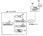
- FIG. 1 is a diagram showing an example of the entire system configuration according to the present embodiment.
- Embodiment it is comprised with the electric power grid
- the power system 10 supplies the power obtained by the power generation facility 11 to the transformer 13 via the transmission line 12, and the power transformed by the transformer 13 is supplied to the large-scale customer 20 via the distribution line 14. To the building 21, factory 22, supermarket 23, etc. In addition, power is supplied to a school 31 and a community center 32, which are relatively large consumers 30 in a residential area. Furthermore, the electric power transformed by the transformer 40 is supplied to the customer 100 as a general household through the distribution line 41.
- a photovoltaic power generation facility (PV) 111 that is a facility that receives sunlight and converts it into electric power
- a storage battery 112 that is a facility that can store and take out electricity
- an electric water heater 113 which is equipment for generating hot water and storing it in a hot water storage tank.
- an electric power load device 114 that operates by electric power such as an air conditioner is installed.
- the electric water heater 113 is also one of the power load devices.
- the photovoltaic power generation facility 111, the electric water heater 112, and the power load device 113 are electrically connected to the distribution line 41.
- storing electricity in the storage battery 112 is called charging, and taking out electricity from the storage battery is called discharging.
- the storage battery 112 may have any configuration as long as it can be charged and discharged, or may be a storage battery such as a lithium ion battery or a nickel hydride battery, or a storage means using a capacitor.
- a storage battery provided as a facility in a house as the consumer 100, for example, a storage battery mounted on an automobile owned by the consumer 100 may be connected and used as the storage battery 112.
- the customer energy management device (EMS) 120 is provided as a device for controlling the facilities in the customer 100.
- the consumer energy management device 120 is a device that monitors and controls the state of each device at the consumer end. When the amount of power generated by the solar power generation facility 111 is large, the water heating operation of the electric water heater 113 or the storage battery 112 is performed. And the local production for local consumption control for consuming the photovoltaic power in the customer 100 is performed.
- Each device 111, 112, 113, 114 at the consumer end includes a control device (not shown), but further includes an interface that can communicate with the consumer energy management device 120, and the consumer energy management device 120 includes power consumption. And the like, and a function of receiving a control signal from the consumer energy management device 120 is provided.
- FIG. 2 is a functional block diagram of the consumer energy management apparatus 120.
- the consumer energy management device 120 includes a local production for local consumption control unit 121, a solar power generation amount prediction unit 122, a power demand prediction unit 123, a demand balance prediction unit 124, a solar power surplus power prediction unit 125, and hot water.
- a demand prediction unit 126 is provided.
- the consumer energy management device 120 includes a photovoltaic power generation state monitoring unit 127, a storage battery state monitoring unit 128, a storage battery charge / discharge control unit 129, an electric water heater state monitoring unit 130, and an electric water heater heat storage control unit 131.
- the input / output unit 136 is an external interface through which a user or an external device (devices 111, 112, 113, 114, etc.) inputs data or outputs data to the user or external device.
- the equipment specification data management unit 134 manages data related to the specifications of each equipment installed at the consumer end. That is, the photovoltaic power generation facility 111 is managed including the rated output and the photovoltaic power generation facility power generation amount characteristic data.
- the storage battery 112 is managed including the storage battery's rated capacity, rated charge power, rated discharge power, storage battery loss, and charge / discharge loss.
- the electric water heater 113 is managed including data on average COP (Coefficient of Performance of energy storage operation) and average heat dissipation loss of the hot water tank.
- the rated output of the photovoltaic power generation facility 111 is the maximum photovoltaic power generation facility power generation output that can be expected when there is sufficient solar radiation intensity.
- the solar power generation amount characteristic data is data that associates the solar power generation amount that can be expected with the solar radiation intensity.
- FIG. 3 shows an example of photovoltaic power generation amount characteristic data.
- the PV power generation amount that can be expected at the solar radiation intensity S is P.
- the rated capacity of the storage battery is data representing the maximum amount of power stored in the storage battery 112.
- the rated output is data representing the maximum output of the storage battery 112.
- the storage battery loss is a rate at which the amount of power stored in the storage battery 112 decreases with time, and here, the rate of decrease per hour [%].
- the charge / discharge loss is the ratio [%] of the amount of power lost in the converter or the like that connects the storage battery 112 to the outside when the storage battery 112 is charged / discharged.
- the COP of the heat storage operation of the electric water heater 113 means the energy efficiency of the heat storage operation, means the ratio of the total amount of output energy to the total amount of input energy in the heat storage operation for a certain period, and the average COP is some predetermined values
- the average value of COP values under the conditions of The heat dissipation loss of the hot water tank means the rate [%] that the amount of heat of the hot water in the hot water tank decreases per unit time. Here, it means the rate of decrease per hour, and the average heat dissipation loss and Means an average value of heat dissipation loss values under some predetermined conditions.
- the photovoltaic power generation state monitoring unit 127 acquires and monitors the amount of photovoltaic power generation from the control device of the photovoltaic power generation equipment 111.
- the storage battery state monitoring unit 128 estimates and manages the remaining state of charge of the storage battery 112 and the current state of the chargeable amount by the following method.
- the remaining charge amount in this state is set as the charge capacity of the specification of the storage battery 112, and the chargeable amount is set to zero.
- the subsequent charge / discharge amount is integrated as needed with charge as positive and discharge as negative, and this is managed as the charge / discharge amount integrated value.
- the chargeable amount is updated with a value obtained by subtracting the current charge / discharge amount integrated value from the previous value. If the updated chargeable amount becomes negative, the chargeable amount is set to 0. Set.
- the electric water heater state monitoring unit 130 acquires and monitors the heat storage operation state of the electric water heater 113 from the control device of the electric water heater 113. It is assumed that the heat storage operation state is 1 when the heat storage operation is performed and 0 when the heat storage operation is not performed. Further, the power consumption possible amount of the electric water heater 113 is calculated and monitored as [(1-electric water heater heat storage operation state) ⁇ electric water heater rated power consumption].
- the power demand state monitoring unit 132 monitors the total power consumption in the consumer, and installs a measuring device at the power receiving point from the customer's power distribution system (however, the terminal side of the photovoltaic power generation facility connection point).
- the power consumption may be collected from the control device of each power load device in the consumer and obtained by calculation.
- the customer performance database 135 stores and manages the actual values of daily solar power generation, total power consumption, storage battery charge / discharge, and hot water demand.
- the amount of photovoltaic power generation, the total amount of power consumption, and the amount of charge / discharge of the storage battery are data in increments of a fixed time such as 1 hour or 30 minutes, and the amount of hot water demand is data of the amount of days.
- the photovoltaic power generation amount is stored in the photovoltaic power generation state monitoring unit 127, the total power consumption is stored in the power demand state monitoring unit 132, and the storage battery charge / discharge amount is stored in the storage battery state monitoring unit 128.
- the storage battery charge / discharge amount is managed with positive charge and negative discharge.
- the total amount of hot water demand from the start of the nighttime heat storage operation to the day before the start of the nighttime heat storage operation is managed as the hot water demand for the day.
- the hot water demand is calculated by measuring the power consumption of the electric water heater 113 in the corresponding time zone and summing it, and dividing this by the average COP of the electric water heater 113.
- the average COP of the electric water heater 113 is given in advance from the outside via the input / output unit 136 and is stored and managed in the device specification data management unit 134. If the electric water heater 113 manages the amount of heat stored inside and can be referred from the outside, the data may be used.
- the next day supply and demand prediction table data storage unit 133 stores the next day supply and demand prediction table data.
- next day supply and demand forecast table data manages the predicted values of solar radiation intensity, photovoltaic power generation amount, power demand amount, supply and demand balance amount, solar power surplus power amount, and hot water demand amount at the following day.
- FIG. 4 shows an example in increments of one hour.
- increments in one hour will be described as an example. It is good also as a structure which is not every 1 hour.
- the solar radiation intensity data in the next day supply and demand prediction table data is given from the outside via the input / output unit 136 before the heat storage operation on the night before is started. For example, by connecting to a weather forecast site, solar radiation intensity data is acquired from data such as the weather and temperature of the next day and stored.
- the photovoltaic power generation amount prediction unit 122 reads the solar power generation amount corresponding to the solar radiation intensity on the solar power generation amount characteristic data with reference to the solar radiation intensity data at each time of the next day supply and demand prediction table data, It outputs to the next day supply and demand prediction table data as the amount of photovoltaic power generation at the same time.
- the power demand prediction unit 123 outputs the predicted power demand amount at each time to the next day's supply and demand prediction table data.
- the predicted power demand amount at each time may be, for example, the average value of past actual power consumption data at the same time.
- the target range to be averaged it is conceivable to simply set all of the past fixed period or only the day within the fixed period that matches the weekday / holiday classification of the next day.
- the period to be referred to is given from the outside via the input / output unit 136 in advance.
- the supply and demand balance prediction unit 124 outputs the supply and demand balance amount prediction value at each time to the next day supply and demand prediction table data.
- the supply-demand balance amount prediction value is calculated as a value obtained by subtracting the photovoltaic power generation amount prediction value from the power demand prediction value.
- the photovoltaic power generation surplus power prediction unit 125 outputs the predicted power generation surplus power amount at each time to the next day supply and demand prediction table data.
- the predicted surplus amount of photovoltaic power generation is calculated as a value obtained by subtracting the predicted supply-demand balance amount from a predetermined supply-demand balance reference amount.
- the hot water demand prediction unit 126 outputs the predicted hot water demand amount at each time to the next day's supply and demand prediction table data. For example, based on past daily hot water demand data, the average value of all past fixed periods, or the average value of only the days that match the weekday / holiday classification of the next day in the actual data It is conceivable that it is calculated and used as the daily hot water demand forecast value for the next day, and a value of 1/24 is output as the hot water demand forecast value at each time.
- an electric water heater heat storage control unit receives an activation signal for suppressing the heat storage operation of the electric water heater 113 at night.
- the solar power generation amount monitoring unit 127 periodically acquires the solar power generation amount, and the power demand state monitoring unit 132 acquires the total power consumption amount.
- the storage battery 112 By subtracting the amount of power generated by the power generation facility and setting this as the supply and demand balance amount, if the supply and demand balance amount falls below the supply and demand balance reference amount, which is a predetermined reference value, the storage battery 112
- the control content for increasing the supply and demand balance amount is determined by starting charging and the heat storage operation of the electric water heater 113, and based on the result, the storage battery charge / discharge control unit 129 stores the storage battery.
- the charge activation signal of the storage battery 112 includes charge amount target value data
- the heat storage operation suppression signal includes suppression rate data
- the heat storage operation activation signal includes power consumption target value data.
- control content determination process for increasing the daytime supply and demand balance will be described later. Further, the processing of the local production for local consumption control unit 121 is executed until a local production for local consumption stop signal is received from the outside such as a user via the input / output unit 136.
- the storage battery charge / discharge control unit 129 When the storage battery charge / discharge control unit 129 receives the storage battery charge activation signal, the storage battery charge / discharge control unit 129 transmits a charge activation signal including charge amount target value data to the control device of the storage battery 112.
- the electric water heater heat storage control unit 131 When the electric water heater heat storage control unit 131 receives the heat storage operation suppression signal, the electric water heater heat storage control unit 131 transmits the heat storage operation suppression signal including the suppression rate data to the control device of the electric water heater 113 and receives the heat storage operation start signal. A heat storage operation start signal including power consumption target value data is transmitted to the control device of the water heater 113.
- control device of the storage battery 112 When the control device of the storage battery 112 receives the charge activation signal, it performs charging with the received charge power of the target charge amount. However, when the charge amount target value exceeds the rated charge power, the battery is charged with the charge power of the rated charge power and charged within the chargeable range of the storage battery 112.
- the controller of the electric water heater 113 normally performs a heat storage operation in advance in a predetermined time zone at night (hereinafter referred to as a night heat storage time zone) in preparation for hot water demand on the next day, and supplies hot water to the hot water storage tank. Process to save. Furthermore, if the hot water is insufficient the next day, a process for additionally storing the hot water is performed (this may be referred to as “boiling operation”).
- storing hot water in the hot water storage tank means increasing the temperature of the hot water in the hot water storage tank, and if the amount of hot water in the hot water storage tank decreases, replenishing the water and increasing the amount of hot water It is to let you.
- the control device of the electric water heater 113 When the control device of the electric water heater 113 receives the heat storage operation suppression start signal from the consumer energy management device 120, the control device suppresses the heat storage amount at night on the previous day only by the control rate given from normal.
- the heat storage suppression is performed by interrupting the heat storage operation before the end condition of the normal heat storage operation is satisfied.
- an index heat storage operation end reference index
- the value of at least one heat storage operation end reference index is as follows:
- the heat storage operation may be interrupted when the condition is satisfied.
- the heat storage operation end reference index may vary depending on the electric water heater, for example, the heat storage duration, the time, the temperature sensor value in the hot water storage tank, and the like are conceivable.
- the control apparatus of an electric water heater will perform control which starts the heat storage operation of the daytime on the day, if the heat storage operation start signal is received from a consumer energy management apparatus.
- the heat storage operation is performed by activating a boiling-up operation that is a heat storage operation that is performed when normal daytime hot water is insufficient. When the boiling increase operation end condition is satisfied, the heat storage operation ends.
- the calculation of the suppression rate of nighttime heat storage operation suppression in the local production for local consumption control unit 121 is performed as follows. The processing flow is shown in the flowchart of FIG.
- step S11 calculation of the total amount of surplus power of photovoltaic power generation is performed the next day (step S11).
- the predicted value of solar power surplus power at each time in the next day supply and demand prediction table data is summed, and this is used as the total power surplus power of the next day.
- step S12 it is determined whether the total amount of surplus power of photovoltaic power generation exceeds 0 or 0.
- step S14 the hot water decrease amount at each time in the daytime time zone is calculated (step S14).
- the daytime time zone the time zone other than the nighttime heat storage time zone in the next day supply and demand prediction table data
- the start time of the daytime zone is set to TDs
- the end time is set to TDe.
- the hot water decrease amount ⁇ HW (t) at each time in the daytime time zone is calculated for each time t in the daytime time zone by the following formula.
- ⁇ HW (t) DHW (t) ⁇ GPV (t) / COP
- DHW (t) Hot water demand at time t
- GPV (t) Solar power generation at time t
- COP Average COP of electric water heater
- the suppression rate of nighttime heat storage suppression is calculated by the following equation (step S16).
- the determination process of the content of the control which increases the daytime supply-demand balance amount in the local production for local consumption control part 121 is performed by the process shown in the flowchart of FIG.
- an increase target amount of the supply and demand balance amount is calculated (step S21).
- the amount of photovoltaic power generation from the photovoltaic power generation state monitoring unit 127 and the total amount of power consumption from the power demand state monitoring unit 132 are obtained, and the supply and demand balance amount is calculated as described above, and the supply and demand balance amount is calculated from the supply and demand balance reference amount. The value obtained by subtracting is used as the target increase in supply and demand balance.
- step S22 the process proceeds to step S22, and the priority order of the storage battery charging start-up and the electric water heater heat storage operation start-up is determined.
- the rated output of the storage battery 112, storage battery loss and charge / discharge loss data, and heat dissipation loss data of the electric water heater 113 are acquired from the device specification data management unit 134.
- the current value of the chargeable amount of the storage battery 112 is acquired from the storage battery state monitoring unit 128, and the current value of the electric power consumption amount of the electric water heater 113 is acquired from the electric water heater state monitoring unit 130.
- the value obtained by summing the storage battery loss and the charge / discharge loss of the storage battery 112 is compared with the value of the heat dissipation loss of the electric water heater 113. If the former is small, the storage battery charging start is prioritized; Priority shall be given to the start of storage heat storage operation.
- the comparison and determination in step S22 may be changed depending on the state in which the system is operating.
- the determination may be made after taking into account operational conditions such as outside air temperature and humidity. Specifically, for example, when the outside air temperature is lower than the reference temperature, the heat dissipation loss of the electric water heater 113 is set larger than the reference value, and when the outside air temperature is higher than the reference temperature, the heat dissipation loss of the electric water heater 113 is reduced. It is also possible to make a change smaller than the reference value and compare the changed heat dissipation loss.
- the storage battery loss and charge / discharge loss of the storage battery 112 may also be changed.
- the storage battery loss and the charge / discharge loss may be increased on the assumption that the deterioration of the storage battery 112 is progressing depending on the operation status such as the date and time since the storage battery 112 is installed.
- step S31 If it is determined in step S22 that the electric water heater heat storage operation start is prioritized, it is determined whether or not “electric water heater power consumption> 0” (step S31).
- the heat storage operation of the electric water heater 113 is started (step S32), and the electric power consumption target value is the electric water heater electric power consuming amount and supply-demand balance.
- the smaller value of the amount increase target amount is set (step S33).
- step S34 it is determined whether or not “demand balance increase target amount ⁇ power consumption target value> 0” (step S34). If “demand balance increase target amount ⁇ power consumption target value> 0”, the storage battery Assume that charging is started (step S35), and the charge amount target value is a value of “demand balance increase target amount ⁇ power consumption target value” (step S36).
- step S34 if “supply / demand balance increase target amount ⁇ power consumption target value> 0” is not satisfied, the process proceeds to step S38, and the storage battery charging is not started.
- step S23 it is determined whether or not “storage battery chargeable amount> 0” (step S23).
- the storage battery charging operation is started (step S24), and the charge amount target value is a smaller value of the storage battery chargeable amount and the supply / demand balance amount increase target amount. (Step S25).
- step S26 it is determined whether or not “demand balance increase target amount ⁇ charge target value> 0” (step S26). If “demand balance increase target amount ⁇ charge target value> 0”, the electric water heater 113 is determined.
- the power consumption target value is a value of “demand balance increase target amount ⁇ charge target value” (step S28).
- the consumer energy management device 120 and the electric water heater 113 operate in a coordinated manner, so that control for absorbing the solar power surplus power by the electric water heater 113 at the consumer end is performed.
- FIG. 7 and 8 are diagrams for explaining an example of a state where local production and consumption of solar power is performed in the system configuration of the present embodiment.
- FIG. 7 (a) shows the integrated value of the heat supply amount for heat storage of the electric water heater 113 as a change in time of one day.
- Characteristic P1 is an example when solar power (PV) is not used for boiling. In this case, boiling is completed at night (until 7 am in this example) until midnight. No boiling is performed.
- the characteristic P2 in the case of this example is up to the pre-heat storage target amount at the time of photovoltaic power generation local production for local consumption as boiling at night power, and then the surplus power of solar power generation is used. Then, it is heated up in the daytime and reaches the normal pre-heat storage target amount.
- the characteristic P3 is when the surplus power of solar power generation is larger than predicted. In this case, when the normal pre-heat storage target amount is reached, surplus power of solar power generation beyond that is not absorbed.
- the characteristic P4 is the case where the surplus power of photovoltaic power generation is less than predicted, and in this case, the heat storage amount is smaller than the normal preliminary heat storage target amount, and therefore, the characteristic P4 is more than the nighttime power. Heat is stored using expensive daytime electricity.
- FIG. 7B is a view of the hot water storage tank of the electric water heater 113 as it is stored.
- the heat storage remaining amount is set as a difference from the reference by setting a certain standard for the amount of heat of the hot water in the hot water storage tank.
- Characteristic H1 is an example in the case where PV (PV) is not used for boiling. In this case, after boiling is completed at night and reaches a normal heat storage target value, it is late at night. The remaining amount of hot water will only decrease until boiling begins.
- the characteristic H2 in the case of this example is up to the pre-heat storage target amount at the time of local generation and local consumption of photovoltaic power generation as boiling at night power, and then boiling and hot water by photovoltaic power generation At nighttime when there is consumption and solar power generation is not performed, the remaining amount of hot water is the same as the characteristic H1 that does not use solar power generation.
- FIG. 8 is a diagram showing a state where solar power generation surplus power is absorbed by the electric water heater 113.
- the vertical axis represents the amount of power
- the horizontal axis represents time.
- the characteristic a shown in FIG. 8 is the power generation amount of solar power generation, and the characteristic b is surplus power of solar power generation.
- the broken line characteristic c indicates the power consumption of the electric water heater 113, and in addition to the nighttime heat storage operation, the heating operation is performed in the daytime.
- FIG. 7 and 8 show the relationship between the solar power generation facility and the electric water heater, but the storage battery is also operated under the conditions shown in the flowchart of FIG. Discharged.
- the control device of the electric water heater 113 controls the number of rotations of the compressor, so that the electric power consumption during the heating operation of the electric water heater 113 is reduced.
- the heating operation may be performed using the power consumption target value received from the consumer energy management device 120.
- the control apparatus of the electric water heater 113 receives the heat storage suppression start signal and the suppression rate from the consumer energy management apparatus 120 for the control of the heat storage suppression of the electric water heater 113 in the local production for local consumption,
- finish conditions according to a suppression rate it is good also as the following structure.
- the electric water heater heat storage control unit 131 of the consumer energy management device 120 acquires the data of the heat storage operation end reference index type and its reference value, which is the heat storage operation end condition data, from the control device of the electric water heater 113, Further, the current value of the index is periodically acquired, and it is determined that the heat storage operation is interrupted when the value of at least one heat storage operation end reference index satisfies the following conditions, and the energization state of the electric water heater 113 is determined.
- the heat storage operation of the electric water heater 113 may be interrupted from the outside by turning it off.
- This processing method is intended to avoid the downside risk of solar power generation during the daytime.
- the nighttime heat storage operation is performed as usual, so even if the surplus power of solar power generation during the day is less than expected, the consumption of daytime electricity is higher than that of nighttime electricity. However, the risk of increased by local production and consumption control can be avoided.
- An example of the second embodiment is an example in which a customer energy management device is a grid-coordinated local production for local consumption operation system that operates in cooperation with the grid operation system of the power system.
- FIG. 9 is a diagram showing an example of the entire system configuration according to the present embodiment.
- a grid operation system 51 and a customer cooperation server 52 are added, and the consumer energy management apparatus is changed to a grid cooperation type consumer energy management apparatus 220.
- the customer cooperation server 52 is connected to the system operation system 51 and the system cooperation type consumer energy management device 52 through the communication network 60.
- the grid operation system 51 monitors the state of the power system and performs various controls for stably supplying power to consumers with high efficiency.
- distribution control for the purpose of maintaining the voltage of each point in the distribution system within the specified range, distribution control for operating various voltage regulators on the distribution system and maintaining the frequency of the power system within the specified range.
- the purpose is to perform supply and demand control that adjusts the output of each generator so that the total demand and total power generation of the entire power system are balanced.
- the grid operation system 51 predicts the status of the power system on the next day using the status monitoring data of the power system.
- the state of the power system to be predicted includes the demand amount and voltage state at each point of the distribution system, and the total demand amount and total power generation state of the entire power system.
- the customer cooperation server 52 acquires the prediction result of the power system state of the next day from the grid operation system 51, and the demand forecast value of the power receiving point of the customer 200 in which the grid cooperative consumer energy management device 220 is installed, The voltage predicted value is extracted, and further, the supply / demand balance amount prediction value of the next day is acquired from the consumer energy management device 220, and the demand / supply balance amount prediction value is subtracted from the demand prediction value to obtain the value as the demand amount increase target value. .
- the demand increase target value becomes negative, it is replaced with 0.
- the system cooperative local energy production / consumption operation is started in the system cooperative consumer energy management device 220. Send a signal.
- the grid coordinated local production for local consumption start signal includes the demand increase target value.
- the customer 200 receives solar light and converts it into electric power, a photovoltaic power generation facility 211, a storage battery 212 that is a facility capable of storing and taking out electricity, and heating water using electricity to supply hot water.
- An electric water heater 213 which is a facility to be generated and stored in a hot water storage tank and a power load device 214 are provided.
- the grid cooperative consumer energy management apparatus 220 outputs a local production / local consumption start signal from the consumer cooperation server 52 to the input / output unit 236. And controls the equipment in the customer 200 according to the local production for local consumption activation signal.
- FIG. 10 is a functional block diagram of the grid cooperative customer energy management apparatus 220.
- the system cooperation type consumer energy management device 220 includes a system cooperation type local production for local consumption control unit 221 instead of the local production for local consumption control unit 121 of the customer energy management device 100 of FIG.
- the configuration of the grid-coordinated consumer energy management device 220 will be briefly described.
- the solar power surplus power prediction unit 225 and the hot water demand prediction unit 226 are provided.
- the consumer energy management device 220 includes a photovoltaic power generation state monitoring unit 227, a storage battery state monitoring unit 228, a storage battery charge / discharge control unit 229, an electric water heater state monitoring unit 230, and an electric water heater heat storage control unit 231.
- the system coordinating type local production for local consumption control unit 221 is a system coordinated local production for local consumption control signal via the input / output unit 236.
- the following processing is performed until a stop signal is received again. That is, the start signal for suppressing the heat storage operation of the electric water heater 213 is sent to the electric water heater heat storage control unit 231 at night.
- This heat storage operation suppression start signal includes suppression rate data, and the value of the suppression rate is set by the same process as in the first embodiment.
- the following processing is performed according to the reception status of the grid coordinated local production for local consumption activation signal and the local production for local consumption control activation signal.
- the system cooperation type local production for local consumption operation system more reliably avoids the generation of solar power generation at the customer end from being suppressed by the system state such as voltage, and reduces the amount of power generation. It is possible to increase power generation and consumption with lower carbon and more efficient.
- the example of 3rd Embodiment is an example made into the community local production for local consumption operation system in which a consumer energy management apparatus operate
- FIG. 11 is a diagram showing an example of the overall configuration according to the present embodiment.
- a community energy management device 390 is added, and the consumer energy management device is changed to a community-compatible consumer energy management device 350.
- the community energy management device 390 is an energy management device installed in the community center 380, and is connected to the community-compatible consumer energy management devices 314, 322, and 350 of a plurality of consumers in the region via the communication network 331.
- the community-compatible consumer energy management apparatus 314 is an energy management apparatus installed in the consumer 310 (school 311), and controls the storage battery 312 and the electric water heater 313.
- the energy management device 322 is an energy management device of a consumer 320 that includes an electric water heater 320 (not provided with a solar power generation facility).
- the community-compatible consumer energy management apparatus 350 included in the consumer 340 is requested according to a control signal from the community energy management apparatus 390. It has a function of controlling devices in the house 340.
- the consumer 340 is a consumer in which all of the storage battery 342, the electric water heater 343, and the solar power generation facility 342 are installed.
- FIG. 12 is a functional block diagram of the community energy management apparatus 390 installed in the community center 380.
- the community energy management device 390 includes an input / output unit 392, a customer energy management device communication unit 393, a customer data management unit 395, a community state monitoring unit 394, and a community local production for local consumption control unit 391. .
- the input / output unit 392 is an external interface through which a user or an external device inputs data or outputs data to the user or external device.
- the customer energy management device communication unit 393 controls communication for the community energy management device 390 to exchange data with each customer energy management device.
- the customer data management unit 395 stores and manages the installation status and specification data of each device at the consumer end, which is given from the user or an external device via the input / output unit 392, and, at any time, the customer energy management device communication unit Via 392, each community-compatible consumer energy management device 350 in the region is accessed, and the data on the operation status of each device at the consumer end and the local production for local consumption control by the consumer energy management device 350, etc. Collect and store the data.
- the specification data of the consumer-end equipment includes specification data related to the photovoltaic power generation facility, storage battery, and electric water heater described in the first embodiment.
- the community state monitoring unit 394 monitors the supply and demand balance state in the community, collects and aggregates the supply and demand balance amount of each consumer from the community-compatible consumer energy management device of each consumer, Calculate as the balance between supply and demand.
- the community local production for local consumption control unit 391 When the community local production for local consumption control unit 391 receives a community local production for local consumption activation signal from the outside such as a user via the input / output unit, the community local production for local consumption control unit 391 periodically obtains the total supply and demand balance in the community from the community state monitoring unit during the daytime. , If this falls below the reference value of the total supply and demand balance in the community, which is a predetermined reference value, the demand for starting local production for local consumption control and the amount of adjustment for each consumer are calculated, and each demand determined to start local production for local consumption control A community local pond consumption control activation signal is transmitted to the community-compatible consumer energy management apparatus 350 of the house via the consumer energy management apparatus communication unit.
- the community local production for local consumption control activation signal includes adjustment amount data for each consumer.
- the selection may be made in order from the consumers with the largest value of the average COP ⁇ average heat dissipation loss of the electric water heater. In this case, to reduce the heat dissipation loss when storing hot water that will be stored more than usual at the customer's end longer than usual, and to improve the energy efficiency of the entire community. Can do.
- FIG. 13 is a functional block diagram of the community-compatible consumer energy management device 350.
- the community-compatible consumer energy management device 350 includes a community-compatible local production / local consumption control unit and a local production / local consumption control integration unit in addition to the configuration of the consumer energy management device of FIG. 2 described in the first embodiment. The difference is that the processing of the local production for local consumption control unit is changed accordingly.
- FIG. 13 is a functional block diagram of the community-compatible consumer energy management device 350.
- the community-compatible consumer energy management device 350 includes a community-compatible local production / local consumption control unit and a local production / local consumption control integration
- the local production for local consumption control unit 353 transmits the control signal for adjusting the heat storage operation of the electric water heater to the electric water heater heat storage control unit.
- the data is sent to the control integration unit 351.
- the local production for local consumption control unit 351 When the community local production for local consumption control unit 352 receives the community local production for local consumption start signal via the input / output unit 368, the local production for local consumption control unit 351 sends an activation signal for the heat storage operation of the electric water heater 343 to the local production for local consumption control integration unit 351.
- the heat storage operation start signal includes power consumption target value data, and the value is the value of the adjustment amount received by the community local production for local consumption start signal.
- the local production for local consumption control integration unit 351 receives the control signal from only one of the local production for local consumption control unit 353 and the community-based local production for local consumption control unit 352, and if it receives from both, The heat storage activation control signal is prioritized over the heat accumulation suppression control signal, and in the case of both the heat accumulation activation control signals, the one with the larger power consumption target value is adopted, and the electric water heater heat accumulation suppression unit 363 is adopted.
- the control signal of heat storage suppression and heat storage start is sent.
- the community-compatible consumer energy management device 350 includes a photovoltaic power generation amount prediction unit 354, a power demand prediction unit 355, a demand balance prediction unit 356, a solar power surplus power prediction unit 357, and a hot water demand prediction unit 358.
- the photovoltaic power generation state monitoring unit 359, the storage battery state monitoring unit 360, the storage battery charge / discharge control unit 361, the electric water heater state monitoring unit 362, the electric water heater heat storage control unit 363, and the power demand state monitoring unit 364 The next day demand forecast table data storage unit 365, a device specification data management unit 366, a customer performance database 367, and an input / output unit 368 are provided.
- the local production / local consumption control integration unit 351, the community-based local production / local consumption control unit 352, and the local production / local consumption control unit 353 other than the local production / local consumption control integration unit 351 described above are the units of the energy management device 120 described in the first embodiment. Similar processing is performed.
- FIG. 14 is a diagram showing a state where solar power generation surplus power is absorbed by the electric water heater 343.
- FIG. 14 is a diagram similar to FIG. 8 described in the first embodiment.
- Photovoltaic power that cannot be absorbed by a single consumer can be absorbed by another consumer's electric water heater or storage battery.
- the solar power generation surplus electric power of another consumer can be combined and the electric water heater's rating or more can be secured.
- FIG. 15 to FIG. 16 portions corresponding to FIG. 1 to FIG. 14 described in the first, second and third embodiments are denoted by the same reference numerals.
- An example of the fourth embodiment is a system-coordinated community local production for local consumption in which a consumer energy management apparatus operates in cooperation with a plurality of consumers, and operates in cooperation with a power system operation system. This is an example of an operational system.
- FIG. 15 is a diagram showing an example of the overall configuration according to the present embodiment.
- the system configuration of FIG. 15 in the fourth embodiment is a system configuration in which the system configuration of the second embodiment shown in FIG. 9 is combined with the system configuration of the third embodiment shown in FIG. It is.
- the community energy management device is configured as a grid-coordinated community energy management device 490.
- the devices 414, 422, and 450 are communicably connected via a communication network 431 and the like, and operate in cooperation with each other.
- the customer cooperation server 510 performs the same processing as the customer cooperation server 52 described in the second embodiment.
- the grid-coordinated community-based community energy of the community center 480 is used as the grid coordination community local production for local consumption activation signal. It transmits to the management apparatus 490.
- the grid cooperative community local production for local consumption activation signal includes the demand increase target value as in the second embodiment.
- the community-compatible customer energy management device 450 performs the same processing with the same configuration as the community-compatible customer energy management device 350 of the third embodiment. That is, the community-compatible consumer energy management device 450 installed in the consumer 440 controls the storage battery 442 and the electric water heater 443. The consumer 440 also includes a power load device 444.
- the customer 410 which is the school 411 is equipped with the storage battery 412 and the electric water heater 413, and is controlled by the community-compatible consumer energy management apparatus 414.
- the community-compatible consumer energy management device 422 is an energy management device of the consumer 420 that includes the electric water heater 420 (not provided with solar power generation facilities).
- FIG. 16 is a functional block diagram of the system cooperation type community energy management device 490.
- the grid-coordinated community energy management device 490 includes a grid-coordinated community local production for local consumption control unit and a community local production for local consumption control integration unit 491. The difference is that the processing of the local production for local consumption control unit 492 is changed.
- Other configurations of the community energy management device 390 include an input / output unit 497, a consumer energy management device communication unit 494, a customer data management unit 496, a community state monitoring unit 495, a system-coordinated community local production for local consumption And a control unit 496.
- the grid cooperative community local production for local consumption control unit 493 receives either or both of the grid cooperative community local production for local consumption start signal and the community local production for local consumption start signal via the input / output unit 497, the following is periodically performed.
- Process determine the consumers to be activated for grid-coordinated community local production for local consumption control and their adjustment amount, and communicate with each customer's community-compatible consumer energy management device 450, etc.
- a community local production for local consumption control activation signal is transmitted via the unit 494.
- the community local production for local consumption control activation signal includes adjustment amount data for each consumer. This process is repeatedly executed until a stop signal is received from the outside such as a user via the input / output unit 497.
- a community state monitoring unit 495 obtains the total supply / demand balance in the community, and subtracts this from the total supply / demand balance reference in the community. If the obtained value is larger than the previously calculated in-community solar power surplus power amount, the value of the in-community solar power surplus power amount is updated with that value.
- Electric water heater power consumption is selected in order from the consumers with the largest average COP of electricity water heaters The possible amount is totaled, and the selection is finished when the surplus amount of solar power in the community is exceeded.
- ⁇ Set the adjustment amount of the selected consumer by the electric water heater power consumption possible amount.
- control by system operation and cooperative control in the community are performed in cooperation, so that more solar power surplus power can be absorbed and more efficient operation becomes possible.
Abstract
When energy storage equipment connected to a photovoltaic power generator (PV) is provided at a consumer's end, an optimum operation of the energy storage equipment is enabled in order to maximize the amount of power to be generated by the photovoltaic power generator. An energy management system, provided with a management unit that controls losses in storage batteries and heat radiation losses in an electric water heater, conducts a control wherein energy storage equipment with small losses is used in priority for absorbing the amount of PV power generated. The energy management system is provided with a power-grid operation calculation unit for estimating voltage distribution within the power distribution system or the amount of supply-demand balance of the whole power grid system the next day, using monitoring data of the state of the power-grid, and calculates a target demand-amount-increase value necessary for avoiding alleviation of the amount of PV power to be generated at the consumer's end, using the voltage distribution within the power distribution system or the amount of supply-demand balance the next day, and also conducts a grid cooperation type control that controls the energy storage equipment so as to have the target demand-amount-increase value satisfied at the consumer's end. Further, the energy management system conducts a control wherein, when the capacity of the energy storage equipment within a consumer's premise is insufficient for absorbing the amount of PV power to be generated therein, the amount of PV power to be generated is absorbed by energy storage equipment of other consumers.
Description
本発明は、需要家端の太陽光発電設備、蓄電池、電気温水器などのエネルギー機器を運用する際に適用されるエネルギーマネジメントシステム、及びそのシステムに適用される需要家又はその需要家の近傍に設置されるエネルギーマネジメント装置に関する。
The present invention is an energy management system applied when operating energy equipment such as a solar power generation facility, a storage battery, and an electric water heater at the consumer's end, and a customer applied to the system or in the vicinity of the customer. It relates to installed energy management equipment.
地球環境負荷低減に向けて太陽光発電設備の導入拡大が見込まれるが、太陽光発電設備の電力系統への連系拡大において、配電系統における太陽光発電電力の逆潮流により電圧が上昇して電圧制御に影響を与えることや、系統全体の供給力が増大して需給バランス制御に影響を与えることなどが懸念されている。
The introduction of photovoltaic power generation equipment is expected to expand to reduce the global environmental load, but in the expansion of the interconnection of photovoltaic power generation equipment to the power system, the voltage increases due to the reverse power flow of the photovoltaic power generation in the distribution system. There are concerns that it will affect the control, and that the supply capacity of the entire system will increase, affecting the balance between supply and demand.
その対策の1つの方法として、需要家端に設置されている電気温水器の蓄熱運転の時間帯を調整することが検討されている。つまり、電気温水器は、通常、夜間の割安な電気を活用して温水を貯湯タンクに貯め、翌日の昼間に温水を使用するという運転を行うが、翌日の昼間の太陽光発電量が多いと予想される場合には、前日夜間の蓄熱運転を抑制して翌日の蓄熱可能量を増大させておき、翌日昼間の太陽光発電量が多い時間帯にあわせて蓄熱運転を行うことで電力需要を増大させ、前述の配電系統における逆潮流や、系統全体の供給力増大を低減することが検討されている(例えば、非特許文献1参照)。
As one of the countermeasures, adjusting the time zone for the heat storage operation of the electric water heater installed at the consumer end is being studied. In other words, electric water heaters are usually operated by using cheap electricity at night to store hot water in a hot water storage tank and using hot water in the daytime of the next day. If anticipated, reduce the heat storage operation at night the previous day to increase the amount of heat storage possible the next day, and perform the heat storage operation during the daytime when there is a large amount of solar power generation during the day. Increasing and reducing the reverse power flow in the aforementioned distribution system and the increase in supply capacity of the entire system have been studied (for example, see Non-Patent Document 1).
この方法の特徴は以下にある。つまり、昼間の太陽光発電の発電によって前記のような配電電圧の上昇などが生じると、太陽光発電設備の電圧上昇抑制機能によって発電量が自動的に抑制されるが、その抑制分を電気温水器の蓄熱運転で有効活用することができるという点、特に、一般的に、需要家における温水需要は、昼間の太陽光発電設備が発電している時間帯以降にも十分な量があり、前記のように蓄熱運転の時間帯を前日夜間から昼間の太陽光発電設備が発電している時間帯にずらしても、温水が不足するということはなく、需要家の利便性を損なわないという点、温水利用のために設置済みの電気温水器を活用するため、特別の初期費用がかからない点に特徴がある。
The features of this method are as follows. In other words, when the distribution voltage rises as described above due to daytime photovoltaic power generation, the amount of power generation is automatically suppressed by the voltage increase suppression function of the photovoltaic power generation facility. In general, the demand for hot water in the consumer is sufficient even after the time period when the solar power generation facility is generating electricity in the daytime. As described above, even if the heat storage operation time is shifted from the night before to the time when the solar power generation facility generates power during the daytime, there is no shortage of hot water and the convenience of consumers is not impaired. It is characterized by the fact that no special initial costs are incurred because the installed electric water heater is used for hot water use.
今後、需要家端等に蓄電池が導入されてくると、蓄電池も電気温水器と同様に、太陽光発電量の吸収に活用することが期待される。つまり、太陽光発電量が多い時間帯に蓄電池を充電することが考えられる。このとき、蓄電池と電気温水器では、蓄電池の蓄電ロスと電気温水器の放熱ロスの違いから、トータルのエネルギー効率の点で、太陽光発電量の吸収にあたって、蓄電池充電と電気温水器蓄熱を組み合わせた最適な運用方法が課題となる。
In the future, if a storage battery is introduced at the end of the customer, it is expected that the storage battery will be used to absorb the amount of photovoltaic power generation as well as an electric water heater. That is, it is conceivable to charge the storage battery during a time period when the amount of solar power generation is large. At this time, in storage battery and electric water heater, due to the difference between the storage battery storage loss and the electric water heater heat dissipation loss, the combination of storage battery charging and electric water heater heat storage in the absorption of photovoltaic power generation in terms of total energy efficiency The optimal operation method becomes a problem.
また、例えば配電系統の電圧分布は、その需要家の状況だけでなく、配電系統全体の負荷状況等に影響を受けるため、需要家端で同じように需要量増大させても、配電系統の状態によっては、やはり太陽光発電設備の電圧上昇抑制機能が動作して発電量が抑制されてしまう可能性がある。
In addition, for example, the voltage distribution of the distribution system is affected not only by the situation of the customer but also by the load situation of the entire distribution system, etc. Depending on the situation, there is a possibility that the voltage increase suppressing function of the photovoltaic power generation facility operates and the power generation amount is suppressed.
さらに、例えば太陽光発電設備の発電量が大きく、需要家端の電気温水器や蓄電池の容量を超える場合には、やはり太陽光発電設備の発電量を抑制せざるを得ない状況が発生する可能性がある。太陽光発電量を吸収できる負荷の量をいかに確保するかが課題である。
Furthermore, for example, if the amount of power generated by the solar power generation facility is large and exceeds the capacity of the electric water heater or storage battery at the consumer end, it is possible that the amount of power generated by the solar power generation facility must be suppressed. There is sex. The challenge is how to secure the amount of load that can absorb solar power.
本発明は前記した課題を解決するためになされたものであり、太陽光発電量のエネルギー貯蔵設備による吸収において、トータルのエネルギー効率向上のため、太陽光発電設備の電圧上昇抑制機能の回避のため、吸収可能量の最大化のためのエネルギー貯蔵設備の最適な運用を可能とする手段を提供することを目的とする。
The present invention has been made to solve the above-described problems, and in order to improve the total energy efficiency in the absorption of the amount of photovoltaic power generation by the energy storage facility, to avoid the voltage rise suppression function of the photovoltaic power generation facility. An object of the present invention is to provide a means that enables the optimum operation of an energy storage facility for maximizing the amount that can be absorbed.
本発明のエネルギーマネジメントでは、蓄電池のロスや電気温水器の放熱ロスなどのエネルギー効率に関するデータを管理し、エネルギー効率の良いエネルギー貯蔵設備を優先して太陽光発電量吸収に用いる制御を行う。
In the energy management of the present invention, data relating to energy efficiency such as storage battery loss and heat dissipation loss of electric water heaters is managed, and control using energy storage equipment with good energy efficiency is given priority for absorption of photovoltaic power generation.
またこの場合に、好ましくは、電力系統の状態監視データを用いて翌日の配電系統の電圧分布や系統全体の需給バランス量を予測する系統運用計算部と、系統運用計算部から翌日などの所定時の配電系統の電圧分布又は需給バランス量の予測情報を取得して、それらを用いて需要家端での太陽光発電量抑制回避に必要な需要量増加目標値を計算する需要家連携計算部とを備えて、制御部で、需要家連携計算部から需要量増加目標値を取得して、需要家端でその需要量増加目標値を満たすようにエネルギー貯蔵設備の制御を行う。
In this case, preferably, the system operation calculation unit for predicting the voltage distribution of the distribution system for the next day or the balance of supply and demand for the entire system using the state monitoring data of the power system, and a predetermined time such as the next day from the system operation calculation unit. A customer cooperation calculation unit that obtains prediction information of the voltage distribution or supply / demand balance amount of the distribution system of the power supply, and calculates a demand increase target value necessary for avoiding the suppression of the amount of photovoltaic power generation at the customer end using them The control unit acquires the demand amount increase target value from the consumer cooperation calculation unit, and controls the energy storage facility so as to satisfy the demand amount increase target value at the consumer end.
さらにこの場合に、1件の需要家内で太陽光発電量吸収のためのエネルギー貯蔵設備の容量が不足する場合に、近隣の他の需要家のエネルギー貯蔵設備にその太陽光発電量を吸収する制御を行うようにし、また、1件の需要家内でエネルギー貯蔵設備へのエネルギー貯蔵のための太陽光発電量が不足する場合に、近隣の他の需要家の太陽光発電量も含めて、そのエネルギー貯蔵設備へのエネルギー貯蔵の制御を行うようにしたものである。
Furthermore, in this case, when the capacity of the energy storage facility for absorbing the amount of photovoltaic power generation within one customer is insufficient, the control for absorbing the amount of photovoltaic power generation in the energy storage facility of other nearby customers In addition, when there is a shortage of photovoltaic power generation for energy storage in an energy storage facility within a single customer, the energy including the photovoltaic power generation of other nearby customers It controls energy storage in the storage facility.
本発明によれば、太陽光発電設備の電力系統への連系拡大において、電力系統への影響を低減し、また、太陽光発電の発電量を増大させて、低炭素で効率のよい電力発電及び消費を行うことが可能になる。
According to the present invention, in the expansion of the connection of the photovoltaic power generation facility to the power system, the influence on the power system is reduced, and the power generation amount of the solar power generation is increased, so that low-carbon and efficient power generation is achieved. And consumption can be performed.
以下、本発明の実施の形態を、添付図面を参照して以下の順序で説明する。
1.第1の実施の形態(図1~図8)
2.第2の実施の形態(図9~図10)
3.第3の実施の形態(図11~図14)
4.第3の実施の形態(図15~図16)
[1.第1の実施の形態]
本発明の第1の実施の形態のエネルギーマネジメントシステムについて、図1~図8を参照して説明する。 Hereinafter, embodiments of the present invention will be described in the following order with reference to the accompanying drawings.
1. First embodiment (FIGS. 1 to 8)
2. Second embodiment (FIGS. 9 to 10)
3. Third embodiment (FIGS. 11 to 14)
4). Third embodiment (FIGS. 15 to 16)
[1. First Embodiment]
An energy management system according to a first embodiment of the present invention will be described with reference to FIGS.
図1は本実施の形態に係る全体のシステム構成例を示す図である。
FIG. 1 is a diagram showing an example of the entire system configuration according to the present embodiment.
本実施の形態においては、電力会社などが運用する電力系統10と、その電力系統10に接続される需要家20,30,100と、需要家100が備える需要家エネルギーマネジメント装置120とで構成されている。
In this Embodiment, it is comprised with the electric power grid | system 10 which an electric power company etc. operate | use, the consumers 20, 30, 100 connected to the electric power system 10, and the customer energy management apparatus 120 with which the customer 100 is provided. ing.
電力系統10は、発電設備11で得た電力を、送電線12を介して変圧器13に供給し、その変圧器13で変圧された電力を、配電線14を介して大規模な需要家20としてのビル21、工場22、スーパーマーケット23などに供給する。また、住宅地内の比較的大規模な需要家30である、学校31や、コミュニティセンター32にも電力を供給する。さらに、変圧器40で変圧された電力を、配電線41を介して、一般家庭としての需要家100に電力を供給する。
The power system 10 supplies the power obtained by the power generation facility 11 to the transformer 13 via the transmission line 12, and the power transformed by the transformer 13 is supplied to the large-scale customer 20 via the distribution line 14. To the building 21, factory 22, supermarket 23, etc. In addition, power is supplied to a school 31 and a community center 32, which are relatively large consumers 30 in a residential area. Furthermore, the electric power transformed by the transformer 40 is supplied to the customer 100 as a general household through the distribution line 41.
需要家端には、太陽光を受けて電力に変換する設備である太陽光発電設備(PV)111と、電気を貯蔵したり取り出したりできる設備である蓄電池112と、電気を用いて水を加熱して温水を生成し貯湯タンクに蓄える設備である電気温水器113とを備える。また、空調機器など電力により動作する電力負荷機器114が設置されている。電気温水器113も電力負荷機器の1つである。太陽光発電設備111、電気温水器112、電力負荷機器113は、配電線41と電気的に接続している。また、蓄電池112に電気を貯蔵することを充電、蓄電池から電気を取り出すことを放電という。
At the consumer end, a photovoltaic power generation facility (PV) 111 that is a facility that receives sunlight and converts it into electric power, a storage battery 112 that is a facility that can store and take out electricity, and heat water using electricity And an electric water heater 113 which is equipment for generating hot water and storing it in a hot water storage tank. In addition, an electric power load device 114 that operates by electric power such as an air conditioner is installed. The electric water heater 113 is also one of the power load devices. The photovoltaic power generation facility 111, the electric water heater 112, and the power load device 113 are electrically connected to the distribution line 41. In addition, storing electricity in the storage battery 112 is called charging, and taking out electricity from the storage battery is called discharging.
蓄電池112は、充電と放電が可能な設備であればどのような構成でもよく、リチウムイオン電池やニッケル水素電池などの蓄電池、あるいはコンデンサを使った蓄電手段でもよい。また、需要家100としての家屋が設備として備える蓄電池の他に、例えばその需要家100が所有する自動車に搭載された蓄電池を接続して、蓄電池112として使用してもよい。
The storage battery 112 may have any configuration as long as it can be charged and discharged, or may be a storage battery such as a lithium ion battery or a nickel hydride battery, or a storage means using a capacitor. In addition to a storage battery provided as a facility in a house as the consumer 100, for example, a storage battery mounted on an automobile owned by the consumer 100 may be connected and used as the storage battery 112.
これらの需要家100内の設備を制御する装置として、需要家エネルギーマネジメント装置(EMS)120を備える。
The customer energy management device (EMS) 120 is provided as a device for controlling the facilities in the customer 100.
需要家エネルギーマネジメント装置120は、需要家端の各機器の状態を監視し制御する装置であり、太陽光発電設備111の発電量が多いときに、電気温水器113の水加熱運転や、蓄電池112の充電を行って、その太陽光発電電力を需要家100内で消費する地産地消制御を行う。
The consumer energy management device 120 is a device that monitors and controls the state of each device at the consumer end. When the amount of power generated by the solar power generation facility 111 is large, the water heating operation of the electric water heater 113 or the storage battery 112 is performed. And the local production for local consumption control for consuming the photovoltaic power in the customer 100 is performed.
需要家端の各機器111,112,113,114はそれぞれ図示しない制御装置を備えているが、さらに、需要家エネルギーマネジメント装置120と通信できるインターフェースを備え、需要家エネルギーマネジメント装置120に電力消費量等の状態データを渡したり、需要家エネルギーマネジメント装置120から制御信号を受信する機能を備える。
Each device 111, 112, 113, 114 at the consumer end includes a control device (not shown), but further includes an interface that can communicate with the consumer energy management device 120, and the consumer energy management device 120 includes power consumption. And the like, and a function of receiving a control signal from the consumer energy management device 120 is provided.
図2は、需要家エネルギーマネジメント装置120の機能ブロック図である。
FIG. 2 is a functional block diagram of the consumer energy management apparatus 120.
需要家エネルギーマネジメント装置120は、地産地消制御部121と、太陽光発電量予測部122と、電力需要予測部123と、需要バランス予測部124と、太陽光発電余剰電力予測部125と、温水需要予測部126を備える。さらに需要家エネルギーマネジメント装置120は、太陽光発電状態監視部127と、蓄電池状態監視部128と、蓄電池充放電制御部129と、電気温水器状態監視部130と、電気温水器蓄熱制御部131と、電力需要状態監視部132と、翌日需要予測テーブルデータ記憶部133と、機器仕様データ管理部134と、需要家実績データベース135と、入出力部136とを備える。
The consumer energy management device 120 includes a local production for local consumption control unit 121, a solar power generation amount prediction unit 122, a power demand prediction unit 123, a demand balance prediction unit 124, a solar power surplus power prediction unit 125, and hot water. A demand prediction unit 126 is provided. Further, the consumer energy management device 120 includes a photovoltaic power generation state monitoring unit 127, a storage battery state monitoring unit 128, a storage battery charge / discharge control unit 129, an electric water heater state monitoring unit 130, and an electric water heater heat storage control unit 131. , A power demand state monitoring unit 132, a next day demand prediction table data storage unit 133, a device specification data management unit 134, a customer performance database 135, and an input / output unit 136.
入出力部136は、ユーザや外部装置(機器111,112,113,114など)がデータを入力したり、ユーザや外部装置へデータを出力する外部インターフェースである。
The input / output unit 136 is an external interface through which a user or an external device ( devices 111, 112, 113, 114, etc.) inputs data or outputs data to the user or external device.
機器仕様データ管理部134は、需要家端に設置されている各機器の仕様に関するデータを管理する。即ち、太陽光発電設備111については定格出力、太陽光発電設備発電量特性データを含んで管理する。蓄電池112については、蓄電池の定格容量、定格充電電力、定格放電電力、蓄電池ロス、充放電ロスを含んで管理する。電気温水器113については、蓄熱運転の平均COP(Coefficient of Performance:エネルギー消費効率)、温水タンクの平均放熱ロスのデータを含んで管理する。太陽光発電設備111の定格出力は、十分な日射強度がある場合に期待できる最大の太陽光発電設備発電出力である。太陽光発電量特性データは日射強度に対して期待できる太陽光発電量を対応づけるデータである。
The equipment specification data management unit 134 manages data related to the specifications of each equipment installed at the consumer end. That is, the photovoltaic power generation facility 111 is managed including the rated output and the photovoltaic power generation facility power generation amount characteristic data. The storage battery 112 is managed including the storage battery's rated capacity, rated charge power, rated discharge power, storage battery loss, and charge / discharge loss. The electric water heater 113 is managed including data on average COP (Coefficient of Performance of energy storage operation) and average heat dissipation loss of the hot water tank. The rated output of the photovoltaic power generation facility 111 is the maximum photovoltaic power generation facility power generation output that can be expected when there is sufficient solar radiation intensity. The solar power generation amount characteristic data is data that associates the solar power generation amount that can be expected with the solar radiation intensity.
図3は、太陽光発電量特性データの例を示す。
FIG. 3 shows an example of photovoltaic power generation amount characteristic data.
日射強度Sのときに期待できるPV発電量はPであることを示している。
The PV power generation amount that can be expected at the solar radiation intensity S is P.
蓄電池の定格容量は、蓄電池112に蓄えられる最大の電力量を表すデータである。定格出力は蓄電池112の最大出力を表すデータである。蓄電池ロスは蓄電池112に蓄えてある電力量が時間とともに減少する割合であり、ここでは1時間当たりの減少率[%]とする。充放電ロスは、蓄電池112の充放電の際に蓄電池112と外部を接続する変換器等で失われる電力量の割合[%]である。
The rated capacity of the storage battery is data representing the maximum amount of power stored in the storage battery 112. The rated output is data representing the maximum output of the storage battery 112. The storage battery loss is a rate at which the amount of power stored in the storage battery 112 decreases with time, and here, the rate of decrease per hour [%]. The charge / discharge loss is the ratio [%] of the amount of power lost in the converter or the like that connects the storage battery 112 to the outside when the storage battery 112 is charged / discharged.
電気温水器113の蓄熱運転のCOPとは、蓄熱運転のエネルギー効率を意味し、一定期間の蓄熱運転における出力エネルギー総量の入力エネルギー総量に対する比率を意味し、平均COPとは、予め定めたいくつかの条件下でのCOP値の平均値を意味するものとする。温水タンクの放熱ロスとは、温水タンク内の温水が持つ熱量が単位時間当たりに減少する割合[%]を意味し、ここでは、1時間あたりの減少率を意味し、また、平均放熱ロスとは、予め定めたいくつかの条件下での放熱ロス値の平均値を意味するものとする。
The COP of the heat storage operation of the electric water heater 113 means the energy efficiency of the heat storage operation, means the ratio of the total amount of output energy to the total amount of input energy in the heat storage operation for a certain period, and the average COP is some predetermined values The average value of COP values under the conditions of The heat dissipation loss of the hot water tank means the rate [%] that the amount of heat of the hot water in the hot water tank decreases per unit time. Here, it means the rate of decrease per hour, and the average heat dissipation loss and Means an average value of heat dissipation loss values under some predetermined conditions.
太陽光発電状態監視部127は、太陽光発電量を太陽光発電設備111の制御装置から取得し監視する。
The photovoltaic power generation state monitoring unit 127 acquires and monitors the amount of photovoltaic power generation from the control device of the photovoltaic power generation equipment 111.
蓄電池状態監視部128は、蓄電池112の充電残量、充電可能量の現在状態を下記の方法によって推定管理する。
・予め定めた一定の長時間の間、蓄電池112を充電する。
・この状態の充電残量を蓄電池112の仕様の充電容量とし、充電可能量を0と定める。
・その後の充放電量を、充電をプラス、放電をマイナスとして随時積分し、これを充放電量積分値として管理する。
・予め定めた周期で、充電残量を、前回値にその時点の充放電量積分値を加えて得られる値で更新し、もし、更新後の充電残量が充電容量より大きくなれば、充電残量を充電容量の値に設定する。また、同時に、充電可能量を、前回値からその時点の充放電量積分値を差し引いて得られる値で更新し、もし、更新後の充電可能量が負になれば、充電可能量を0と設定する。 The storage batterystate monitoring unit 128 estimates and manages the remaining state of charge of the storage battery 112 and the current state of the chargeable amount by the following method.
Charge thestorage battery 112 for a predetermined long period of time.
The remaining charge amount in this state is set as the charge capacity of the specification of thestorage battery 112, and the chargeable amount is set to zero.
The subsequent charge / discharge amount is integrated as needed with charge as positive and discharge as negative, and this is managed as the charge / discharge amount integrated value.
Updates the remaining charge level with a value obtained by adding the current charge / discharge amount integral value to the previous value at a predetermined cycle, and if the updated remaining charge level is greater than the charge capacity, the battery is charged. Set the remaining battery charge value. At the same time, the chargeable amount is updated with a value obtained by subtracting the current charge / discharge amount integrated value from the previous value. If the updated chargeable amount becomes negative, the chargeable amount is set to 0. Set.
・予め定めた一定の長時間の間、蓄電池112を充電する。
・この状態の充電残量を蓄電池112の仕様の充電容量とし、充電可能量を0と定める。
・その後の充放電量を、充電をプラス、放電をマイナスとして随時積分し、これを充放電量積分値として管理する。
・予め定めた周期で、充電残量を、前回値にその時点の充放電量積分値を加えて得られる値で更新し、もし、更新後の充電残量が充電容量より大きくなれば、充電残量を充電容量の値に設定する。また、同時に、充電可能量を、前回値からその時点の充放電量積分値を差し引いて得られる値で更新し、もし、更新後の充電可能量が負になれば、充電可能量を0と設定する。 The storage battery
Charge the
The remaining charge amount in this state is set as the charge capacity of the specification of the
The subsequent charge / discharge amount is integrated as needed with charge as positive and discharge as negative, and this is managed as the charge / discharge amount integrated value.
Updates the remaining charge level with a value obtained by adding the current charge / discharge amount integral value to the previous value at a predetermined cycle, and if the updated remaining charge level is greater than the charge capacity, the battery is charged. Set the remaining battery charge value. At the same time, the chargeable amount is updated with a value obtained by subtracting the current charge / discharge amount integrated value from the previous value. If the updated chargeable amount becomes negative, the chargeable amount is set to 0. Set.
電気温水器状態監視部130は、電気温水器113の蓄熱運転状態を、電気温水器113の制御装置から取得し監視する。蓄熱運転状態は、蓄熱運転を行っている場合に1、行っていない場合に0をとるとする。また、電気温水器113の電力消費可能量を、[(1-電気温水器蓄熱運転状態)×電気温水器定格電力消費量]として計算し監視する。
The electric water heater state monitoring unit 130 acquires and monitors the heat storage operation state of the electric water heater 113 from the control device of the electric water heater 113. It is assumed that the heat storage operation state is 1 when the heat storage operation is performed and 0 when the heat storage operation is not performed. Further, the power consumption possible amount of the electric water heater 113 is calculated and monitored as [(1-electric water heater heat storage operation state) × electric water heater rated power consumption].
電力需要状態監視部132は、需要家内の電力消費量トータルを監視するものであり、需要家の配電系統からの受電点(ただし、太陽光発電設備連系点より末端側)に計測装置を設置して監視しても良いし、需要家内の各電力負荷機器の制御装置から電力消費量を収集して計算で求めても良い。
The power demand state monitoring unit 132 monitors the total power consumption in the consumer, and installs a measuring device at the power receiving point from the customer's power distribution system (however, the terminal side of the photovoltaic power generation facility connection point). The power consumption may be collected from the control device of each power load device in the consumer and obtained by calculation.
需要家実績データベース135は、日々の需要家の太陽光発電量、電力消費量トータル、蓄電池充放電量、温水需要量の実績値を保管して管理する。太陽光発電量、電力消費量トータル、蓄電池充放電量は1時間や30分等の一定時間刻みの量、温水需要量は日間の量のデータとする。太陽光発電量は太陽光発電状態監視部127が格納し、電力消費量トータルは電力需要状態監視部132が格納し、蓄電池充放電量は蓄電池状態監視部128が格納する。蓄電池充放電量は、充電をプラス、放電をマイナスとして管理する。温水需要量は、前日夜間の蓄熱運転が開始してから当日夜間の蓄熱運転が開始する前までの総量を、当日の日間の温水需要量として管理する。この温水需要量は、電気温水器113の対応する時間帯の電力消費量を計測して合計し、これを電気温水器113の平均COPで割って計算する。電気温水器113の平均COPはあらかじめ入出力部136を介して外部から与えられ、機器仕様データ管理部134に格納され管理される。電気温水器113が内部で蓄熱量を管理しており、外部から参照することが可能な場合には、そのデータを利用してもよい。
The customer performance database 135 stores and manages the actual values of daily solar power generation, total power consumption, storage battery charge / discharge, and hot water demand. The amount of photovoltaic power generation, the total amount of power consumption, and the amount of charge / discharge of the storage battery are data in increments of a fixed time such as 1 hour or 30 minutes, and the amount of hot water demand is data of the amount of days. The photovoltaic power generation amount is stored in the photovoltaic power generation state monitoring unit 127, the total power consumption is stored in the power demand state monitoring unit 132, and the storage battery charge / discharge amount is stored in the storage battery state monitoring unit 128. The storage battery charge / discharge amount is managed with positive charge and negative discharge. The total amount of hot water demand from the start of the nighttime heat storage operation to the day before the start of the nighttime heat storage operation is managed as the hot water demand for the day. The hot water demand is calculated by measuring the power consumption of the electric water heater 113 in the corresponding time zone and summing it, and dividing this by the average COP of the electric water heater 113. The average COP of the electric water heater 113 is given in advance from the outside via the input / output unit 136 and is stored and managed in the device specification data management unit 134. If the electric water heater 113 manages the amount of heat stored inside and can be referred from the outside, the data may be used.
翌日需給予測テーブルデータ記憶部133は、翌日需給予測テーブルデータを記憶する。
The next day supply and demand prediction table data storage unit 133 stores the next day supply and demand prediction table data.
翌日需給予測テーブルデータの例を図4に示す。翌日需給予測テーブルデータは、翌日の複数時点の日射強度、太陽光発電量、電力需要量、需給バランス量、太陽光発電余剰電力量、温水需要量の予測値を対応づけて管理するものである。図4は1時間刻みの例であり、以下、説明を簡単にするため、1時間刻みの場合を例に説明する。1時間刻みでない構成としてもよい。
An example of the next day supply and demand forecast table data is shown in FIG. The next day supply and demand prediction table data manages the predicted values of solar radiation intensity, photovoltaic power generation amount, power demand amount, supply and demand balance amount, solar power surplus power amount, and hot water demand amount at the following day. . FIG. 4 shows an example in increments of one hour. Hereinafter, in order to simplify the explanation, the case of increments in one hour will be described as an example. It is good also as a structure which is not every 1 hour.
翌日需給予測テーブルデータ中の日射強度データは、前日夜間の蓄熱運転が開始される前に、入出力部136を介して外部から与えられるものとする。例えば、天気予報のサイトに接続して、翌日の天気、気温などのデータから日射強度データを取得して記憶させる。
Suppose that the solar radiation intensity data in the next day supply and demand prediction table data is given from the outside via the input / output unit 136 before the heat storage operation on the night before is started. For example, by connecting to a weather forecast site, solar radiation intensity data is acquired from data such as the weather and temperature of the next day and stored.
太陽光発電量予測部122は、翌日需給予測テーブルデータの各時刻の日射強度データを参照し、太陽光発電量特性データに上で、その日射強度に対応する太陽光発電量を読み取り、これを翌日需給予測テーブルデータに同時刻の太陽光発電量として出力する。
The photovoltaic power generation amount prediction unit 122 reads the solar power generation amount corresponding to the solar radiation intensity on the solar power generation amount characteristic data with reference to the solar radiation intensity data at each time of the next day supply and demand prediction table data, It outputs to the next day supply and demand prediction table data as the amount of photovoltaic power generation at the same time.
電力需要予測部123は、翌日需給予測テーブルデータに各時刻の電力需要量予測値を出力する。各時刻の電力需要量予測値は、たとえば、過去の電力消費量の実績データの同時刻の平均値とすることが考えられる。ここで、平均化する対象範囲としては、単純に過去一定期間の全てとするか、その一定期間内のうち翌日の平日/休日の区分に一致する日のみとするかなどが考えられる。参照する期間については事前に入出力部136を介して外部から与えられるものとする。
The power demand prediction unit 123 outputs the predicted power demand amount at each time to the next day's supply and demand prediction table data. The predicted power demand amount at each time may be, for example, the average value of past actual power consumption data at the same time. Here, as the target range to be averaged, it is conceivable to simply set all of the past fixed period or only the day within the fixed period that matches the weekday / holiday classification of the next day. The period to be referred to is given from the outside via the input / output unit 136 in advance.
需給バランス予測部124は、翌日需給予測テーブルデータに各時刻の需給バランス量予測値を出力する。需給バランス量予測値は、電力需要予測値から太陽光発電量予測値を差し引いた値として計算する。
The supply and demand balance prediction unit 124 outputs the supply and demand balance amount prediction value at each time to the next day supply and demand prediction table data. The supply-demand balance amount prediction value is calculated as a value obtained by subtracting the photovoltaic power generation amount prediction value from the power demand prediction value.
太陽光発電余剰電力予測部125は、翌日需給予測テーブルデータに各時刻の太陽光発電余剰電力量予測値を出力する。太陽光発電余剰電力量予測値は、予め定めた需給バランス基準量から需給バランス量予測値を差し引いた値として計算する。
The photovoltaic power generation surplus power prediction unit 125 outputs the predicted power generation surplus power amount at each time to the next day supply and demand prediction table data. The predicted surplus amount of photovoltaic power generation is calculated as a value obtained by subtracting the predicted supply-demand balance amount from a predetermined supply-demand balance reference amount.
温水需要予測部126は、翌日需給予測テーブルデータに各時刻の温水需要量予測値を出力する。たとえば、過去の日間温水需要量の実績データをもとに、過去一定期間すべての平均値とするか、あるいは、実績データのうち、翌日の平日/休日の区分に一致する日のみの平均値を求めて、それを翌日の日間温水需要量予測値とし、その1/24の値を各時刻の温水需要量予測値として出力することが考えられる。
The hot water demand prediction unit 126 outputs the predicted hot water demand amount at each time to the next day's supply and demand prediction table data. For example, based on past daily hot water demand data, the average value of all past fixed periods, or the average value of only the days that match the weekday / holiday classification of the next day in the actual data It is conceivable that it is calculated and used as the daily hot water demand forecast value for the next day, and a value of 1/24 is output as the hot water demand forecast value at each time.
地産地消制御部121は、入出力部136を介して、ユーザなど外部から地産地消起動信号を受信すると、夜間は、電気温水器113の蓄熱運転抑制の起動信号を電気温水器蓄熱制御部131に送り、また、昼間は、周期的に、太陽光発電状態監視部127から太陽光発電量を、電力需要状態監視部132から電力消費量トータルを取得して、電力消費量トータルから太陽光発電設備発電量を引き算してこれを需給バランス量とし、需給バランス量が予め定めた基準値である需給バランス基準量を下回ると、需給バランス量が需給バランス基準量を上回るように、蓄電池112の充電や電気温水器113の蓄熱運転を起動することで需給バランス量を増加させる制御内容を決定し、その結果に基づいて、蓄電池充放電制御部129に蓄電池の充電起動信号を、電気温水器蓄熱制御部131に電気温水器113の蓄熱運転起動信号をそれぞれ送る。蓄電池112の充電起動信号は充電量目標値データを含み、蓄熱運転抑制信号は抑制率データを含み、蓄熱運転起動信号は電力消費量目標値データを含む。この昼間の需給バランス量を増加させる制御の内容の決定処理の詳細については後述する。また、この地産地消制御部121の処理は、入出力部136を介してユーザなど外部から地産地消停止信号を受信するまで実行される。
When the local production for local consumption control unit 121 receives a local production for local consumption activation signal from the outside such as a user via the input / output unit 136, an electric water heater heat storage control unit receives an activation signal for suppressing the heat storage operation of the electric water heater 113 at night. In the daytime, the solar power generation amount monitoring unit 127 periodically acquires the solar power generation amount, and the power demand state monitoring unit 132 acquires the total power consumption amount. By subtracting the amount of power generated by the power generation facility and setting this as the supply and demand balance amount, if the supply and demand balance amount falls below the supply and demand balance reference amount, which is a predetermined reference value, the storage battery 112 The control content for increasing the supply and demand balance amount is determined by starting charging and the heat storage operation of the electric water heater 113, and based on the result, the storage battery charge / discharge control unit 129 stores the storage battery. Send a charging start signal, the electric water heater thermal storage controller 131 of the thermal storage operation start signal of the electric water heater 113, respectively. The charge activation signal of the storage battery 112 includes charge amount target value data, the heat storage operation suppression signal includes suppression rate data, and the heat storage operation activation signal includes power consumption target value data. Details of the control content determination process for increasing the daytime supply and demand balance will be described later. Further, the processing of the local production for local consumption control unit 121 is executed until a local production for local consumption stop signal is received from the outside such as a user via the input / output unit 136.
蓄電池充放電制御部129は、蓄電池充電起動信号を受信すると、蓄電池112の制御装置に対して、充電量目標値データを含む充電起動信号を送信する。
When the storage battery charge / discharge control unit 129 receives the storage battery charge activation signal, the storage battery charge / discharge control unit 129 transmits a charge activation signal including charge amount target value data to the control device of the storage battery 112.
電気温水器蓄熱制御部131は、蓄熱運転抑制信号を受信すると、電気温水器113の制御装置に対して、抑制率データを含む蓄熱運転抑制信号を送信し、蓄熱運転起動信号を受信すると、電気温水器113の制御装置に対して、電力消費量目標値データを含む蓄熱運転起動信号を送信する。
When the electric water heater heat storage control unit 131 receives the heat storage operation suppression signal, the electric water heater heat storage control unit 131 transmits the heat storage operation suppression signal including the suppression rate data to the control device of the electric water heater 113 and receives the heat storage operation start signal. A heat storage operation start signal including power consumption target value data is transmitted to the control device of the water heater 113.
蓄電池112の制御装置は、充電起動信号を受信すると、受信した充電量目標値の充電電力で充電を実行する。ただし、充電量目標値が定格充電電力を超える場合には定格充電電力の充電電力で充電され、また、蓄電池112の充電容量として充電可能な範囲内で充電される。
When the control device of the storage battery 112 receives the charge activation signal, it performs charging with the received charge power of the target charge amount. However, when the charge amount target value exceeds the rated charge power, the battery is charged with the charge power of the rated charge power and charged within the chargeable range of the storage battery 112.
電気温水器113の制御装置は、通常、翌日の温水需要に備えて、夜間のあらかじめ定める時間帯(以下、夜間蓄熱時間帯という)の中で事前に蓄熱運転を行って、貯湯タンクに温水を蓄える処理を行う。さらに、翌日、温水が不足するような場合には追加で温水を蓄える処理を行う(これを沸き増し運転ということもある)。ここで、貯湯タンクに温水を蓄えるとは、貯湯タンク内の温水の温度を上昇させることをいい、貯湯タンク内の温水の量が減少してきた場合には水を補給して温水の量を増加させることである。
The controller of the electric water heater 113 normally performs a heat storage operation in advance in a predetermined time zone at night (hereinafter referred to as a night heat storage time zone) in preparation for hot water demand on the next day, and supplies hot water to the hot water storage tank. Process to save. Furthermore, if the hot water is insufficient the next day, a process for additionally storing the hot water is performed (this may be referred to as “boiling operation”). Here, storing hot water in the hot water storage tank means increasing the temperature of the hot water in the hot water storage tank, and if the amount of hot water in the hot water storage tank decreases, replenishing the water and increasing the amount of hot water It is to let you.
電気温水器113の制御装置は、需要家エネルギーマネジメント装置120から蓄熱運転抑制起動信号を受信すると、前日夜間の蓄熱量を通常より与えられた抑制率だけ抑制する制御を行う。蓄熱抑制は、通常の蓄熱運転の終了条件が成立する前に、蓄熱運転を中断することで行う。例えば、蓄熱運転終了条件の基準となる指標(蓄熱運転終了基準指標)の値が、また、蓄熱運転終了基準指標が複数ある場合には、少なくとも1つの蓄熱運転終了基準指標の値が下記の条件を満たした時点で蓄熱運転を中断するとしてもよい。蓄熱運転終了基準指標としては、電気温水器によっても異なる可能性があるが、例えば、蓄熱継続時間、時刻、貯湯タンク内の温度センサ値などが考えられる。
When the control device of the electric water heater 113 receives the heat storage operation suppression start signal from the consumer energy management device 120, the control device suppresses the heat storage amount at night on the previous day only by the control rate given from normal. The heat storage suppression is performed by interrupting the heat storage operation before the end condition of the normal heat storage operation is satisfied. For example, when there is a value of an index (heat storage operation end reference index) serving as a reference for the heat storage operation end condition, and there are a plurality of heat storage operation end reference indexes, the value of at least one heat storage operation end reference index is as follows: The heat storage operation may be interrupted when the condition is satisfied. Although the heat storage operation end reference index may vary depending on the electric water heater, for example, the heat storage duration, the time, the temperature sensor value in the hot water storage tank, and the like are conceivable.
|Xi-Xi(s)|≦|Xi(e)-Xi(s)|×(1.0-R/100)
ただし、
Xi:蓄熱運転終了基準指標iの現在の値
Xi(s):蓄熱運転終了基準指標iの蓄熱運転開始時の値
Xi(e):蓄熱運転終了基準指標iの蓄熱運転終了条件の値
R:需要家エネルギーマネジメント装置から受信した抑制率データの値[%]
また、電気温水器の制御装置は、需要家エネルギーマネジメント装置から蓄熱運転起動信号を受信すると、当日昼間の蓄熱運転を起動する制御を行う。蓄熱運転は、通常の昼間の温水不足時に行われる蓄熱運転である沸き増し運転を起動することで行う。沸き増し運転終了条件が成立すると、蓄熱運転が終了する。 | Xi-Xi (s) | ≦ | Xi (e) -Xi (s) | × (1.0-R / 100)
However,
Xi: Current value of heat storage operation end reference index i Xi (s): Value of heat storage operation end reference index i at start of heat storage operation Xi (e): Value of heat storage operation end condition index i of heat storage operation end reference index R: Value of restraint rate data received from customer energy management equipment [%]
Moreover, the control apparatus of an electric water heater will perform control which starts the heat storage operation of the daytime on the day, if the heat storage operation start signal is received from a consumer energy management apparatus. The heat storage operation is performed by activating a boiling-up operation that is a heat storage operation that is performed when normal daytime hot water is insufficient. When the boiling increase operation end condition is satisfied, the heat storage operation ends.
地産地消制御部121における夜間の蓄熱運転抑制の抑制率の計算は、以下に示すように行う。その処理の流れを図5のフローチャートに示す。
The calculation of the suppression rate of nighttime heat storage operation suppression in the local production for local consumption control unit 121 is performed as follows. The processing flow is shown in the flowchart of FIG.
まず、翌日太陽光発電余剰電力量トータルの計算を行う(ステップS11)。ここでは、翌日需給予測テーブルデータの各時刻の太陽光発電余剰電力量予測値を合計し、これを翌日太陽光発電余剰電力量トータルとする。
First, calculation of the total amount of surplus power of photovoltaic power generation is performed the next day (step S11). Here, the predicted value of solar power surplus power at each time in the next day supply and demand prediction table data is summed, and this is used as the total power surplus power of the next day.
そして、その翌日太陽光発電余剰電力量トータルが、0を越えた値か、あるいは0か判断する(ステップS12)。
Then, the next day, it is determined whether the total amount of surplus power of photovoltaic power generation exceeds 0 or 0 (step S12).
ステップS2の判断で、翌日太陽光発電余剰電力トータル=0の場合には、夜間蓄熱抑制の抑制率=0[%]と設定する(ステップS13)。
If it is determined in step S2 that the next day solar power surplus power total = 0, the night heat storage suppression rate is set to 0 [%] (step S13).
また、ステップS2の判断で、翌日太陽光発電余剰電力トータル>0の場合には、昼間時間帯の各時刻の温水減少量の計算を行う(ステップS14)。
In addition, if it is determined in step S2 that the next day solar power surplus power total> 0, the hot water decrease amount at each time in the daytime time zone is calculated (step S14).
ここでは、まず、翌日需給予測テーブルデータの夜間蓄熱時間帯以外の時間帯を昼間時間帯とよび、昼間時間帯の開始時刻をTDs、終了時刻をTDeとおく。
Here, first, the time zone other than the nighttime heat storage time zone in the next day supply and demand prediction table data is called the daytime time zone, the start time of the daytime zone is set to TDs, and the end time is set to TDe.
そして、昼間時間帯の各時刻における温水減少量ΔHW(t)を昼間時間帯の各時刻tについて下式で計算する。
Then, the hot water decrease amount ΔHW (t) at each time in the daytime time zone is calculated for each time t in the daytime time zone by the following formula.
ΔHW(t)=DHW(t)-GPV(t)/COP
ただし、
DHW(t):時刻tにおける温水需要量
GPV(t):時刻tにおける太陽光発電量
COP:電気温水器の平均COP
そして、昼間時間帯の各時刻における必要温水残量MHW(t)を、昼間時間帯の各時刻tについて下式の漸化式で計算する(ステップS15)。 ΔHW (t) = DHW (t) −GPV (t) / COP
However,
DHW (t): Hot water demand at time t GPV (t): Solar power generation at time t COP: Average COP of electric water heater
Then, the required remaining amount of hot water MHW (t) at each time in the daytime zone is calculated by the following recurrence formula for each time t in the daytime zone (step S15).
MHW(t)=max{0, MHW(t+1)-ΔHW(t)} for TDs≦t≦TDe
MHW(Te+1)=0
なお、MHW(t+1)の+1は、時刻tに対して次に基準となる時刻とする処理であり、この例では1時間加算することになる。 MHW (t) = max {0, MHW (t + 1) −ΔHW (t)} for TDs ≦ t ≦ TDe
MHW (Te + 1) = 0
Note that +1 of MHW (t + 1) is processing for setting the next reference time with respect to time t, and in this example, 1 hour is added.
MHW(Te+1)=0
なお、MHW(t+1)の+1は、時刻tに対して次に基準となる時刻とする処理であり、この例では1時間加算することになる。 MHW (t) = max {0, MHW (t + 1) −ΔHW (t)} for TDs ≦ t ≦ TDe
MHW (Te + 1) = 0
Note that +1 of MHW (t + 1) is processing for setting the next reference time with respect to time t, and in this example, 1 hour is added.
さらに、夜間蓄熱抑制の抑制率を下式で計算する(ステップS16)。
Furthermore, the suppression rate of nighttime heat storage suppression is calculated by the following equation (step S16).
抑制率=MHW(Ts)/翌日日間温水需要量予測値×100 [%]
このようにして、地産地消制御部121における夜間の蓄熱運転抑制の抑制率を算出する。 Suppression rate = MHW (Ts) / predicted hot water demand for next day x 100 [%]
Thus, the suppression rate of nighttime heat storage operation suppression in the local production for localconsumption control unit 121 is calculated.
このようにして、地産地消制御部121における夜間の蓄熱運転抑制の抑制率を算出する。 Suppression rate = MHW (Ts) / predicted hot water demand for next day x 100 [%]
Thus, the suppression rate of nighttime heat storage operation suppression in the local production for local
地産地消制御部121における昼間の需給バランス量を増加させる制御の内容の決定処理は、図6のフローチャートに示した処理で実行される。
The determination process of the content of the control which increases the daytime supply-demand balance amount in the local production for local consumption control part 121 is performed by the process shown in the flowchart of FIG.
図6のフローチャートに従って説明すると、まず、需給バランス量の増加目標量の計算が行われる(ステップS21)。
Describing according to the flowchart of FIG. 6, first, an increase target amount of the supply and demand balance amount is calculated (step S21).
ここでは、太陽光発電状態監視部127から太陽光発電量、電力需要状態監視部132から電力消費量トータルを取得し、前述のように需給バランス量を計算し、需給バランス基準量から需給バランス量を差し引いて得られる値を需給バランス量の増加目標量とする。
Here, the amount of photovoltaic power generation from the photovoltaic power generation state monitoring unit 127 and the total amount of power consumption from the power demand state monitoring unit 132 are obtained, and the supply and demand balance amount is calculated as described above, and the supply and demand balance amount is calculated from the supply and demand balance reference amount. The value obtained by subtracting is used as the target increase in supply and demand balance.
次に、ステップS22に移行し、蓄電池充電起動と電気温水器蓄熱運転起動の優先順位の決定を行う。
Next, the process proceeds to step S22, and the priority order of the storage battery charging start-up and the electric water heater heat storage operation start-up is determined.
ここでは、機器仕様データ管理部134から、蓄電池112の定格出力と蓄電池ロスと充放電ロスのデータ、電気温水器113の放熱ロスのデータを取得する。
Here, the rated output of the storage battery 112, storage battery loss and charge / discharge loss data, and heat dissipation loss data of the electric water heater 113 are acquired from the device specification data management unit 134.
また、蓄電池状態監視部128から蓄電池112の充電可能量の現在値を取得し、電気温水器状態監視部130から電気温水器113の電力消費可能量の現在値を取得する。
Also, the current value of the chargeable amount of the storage battery 112 is acquired from the storage battery state monitoring unit 128, and the current value of the electric power consumption amount of the electric water heater 113 is acquired from the electric water heater state monitoring unit 130.
そして、蓄電池112の蓄電池ロスと充放電ロスを合計した値と、電気温水器113の放熱ロスの値を比較し、前者が小さい場合には蓄電池充電起動を優先し、そうでない場合には電気温水器蓄熱運転起動を優先するものとする。
Then, the value obtained by summing the storage battery loss and the charge / discharge loss of the storage battery 112 is compared with the value of the heat dissipation loss of the electric water heater 113. If the former is small, the storage battery charging start is prioritized; Priority shall be given to the start of storage heat storage operation.
なお、このステップS22での比較と決定は、システムを運用している状態によって変わるようにしてもよい。例えば、外気温及び湿度などの運用状況を加味した上で、決定するようにしてもよい。具体的には、例えば外気温が基準温度より低い場合には、電気温水器113の放熱ロスを基準値より大きくし、外気温が基準温度より高い場合には、電気温水器113の放熱ロスを基準値より小さく変更し、その変更された放熱ロスで比較するようにしてもよい。
Note that the comparison and determination in step S22 may be changed depending on the state in which the system is operating. For example, the determination may be made after taking into account operational conditions such as outside air temperature and humidity. Specifically, for example, when the outside air temperature is lower than the reference temperature, the heat dissipation loss of the electric water heater 113 is set larger than the reference value, and when the outside air temperature is higher than the reference temperature, the heat dissipation loss of the electric water heater 113 is reduced. It is also possible to make a change smaller than the reference value and compare the changed heat dissipation loss.
蓄電池112の蓄電池ロスや充放電ロスについても、変化させるようにしてもよい。例えば、蓄電池112を設置してからの年月や充放電回数などの稼働状況によって、蓄電池112の劣化が進んでいるとして、蓄電池ロスや充放電ロスを増加させるようにしてもよい。
The storage battery loss and charge / discharge loss of the storage battery 112 may also be changed. For example, the storage battery loss and the charge / discharge loss may be increased on the assumption that the deterioration of the storage battery 112 is progressing depending on the operation status such as the date and time since the storage battery 112 is installed.
ステップS22で電気温水器蓄熱運転起動が優先の場合には、「電気温水器電力消費可能量>0」か否か判断する(ステップS31)。
If it is determined in step S22 that the electric water heater heat storage operation start is prioritized, it is determined whether or not “electric water heater power consumption> 0” (step S31).
ここで、電気温水器電力消費可能量=0の場合は、電気温水器113の蓄熱運転は起動しないものとする(ステップS37)。
Here, when the electric water heater power consuming amount = 0, it is assumed that the heat storage operation of the electric water heater 113 is not started (step S37).
また、電気温水器電力消費可能量>0の場合は、電気温水器113の蓄熱運転を起動するものとし(ステップS32)、その電力消費量目標値は、電気温水器電力消費可能量と需給バランス量増加目標量の小さい方の値とする(ステップS33)。
When the electric water heater power consuming amount> 0, the heat storage operation of the electric water heater 113 is started (step S32), and the electric power consumption target value is the electric water heater electric power consuming amount and supply-demand balance. The smaller value of the amount increase target amount is set (step S33).
その後、「需給バランス量増加目標量-電力消費量目標値>0」か否か判断し(ステップS34)、「需給バランス量増加目標量-電力消費量目標値>0」の場合は、蓄電池の充電を起動するとし(ステップS35)、その充電量目標値は、「需給バランス量増加目標量-電力消費量目標値」の値とする(ステップS36)。
Thereafter, it is determined whether or not “demand balance increase target amount−power consumption target value> 0” (step S34). If “demand balance increase target amount−power consumption target value> 0”, the storage battery Assume that charging is started (step S35), and the charge amount target value is a value of “demand balance increase target amount−power consumption target value” (step S36).
ステップS34で、「需給バランス量増加目標量-電力消費量目標値>0」でない場合には、ステップS38に移行し、蓄電池充電起動を行わない。
In step S34, if “supply / demand balance increase target amount−power consumption target value> 0” is not satisfied, the process proceeds to step S38, and the storage battery charging is not started.
次に、ステップS22で蓄電池充電起動が優先の場合の処理について説明する。
Next, processing in the case where priority is given to storage battery charging activation in step S22 will be described.
このときには、「蓄電池充電可能量>0」か否か判断する(ステップS23)。ここで、蓄電池充電可能量=0の場合は、蓄電池112の充電は起動しないものとする(ステップS29)。
・蓄電池充電可能量>0の場合は、蓄電池の充電運転を起動するものとし(ステップS24)、その充電量目標値は、蓄電池充電可能量と需給バランス量増加目標量の小さい方の値とする(ステップS25)。 At this time, it is determined whether or not “storage battery chargeable amount> 0” (step S23). Here, when the storage battery chargeable amount = 0, charging of thestorage battery 112 is not started (step S29).
When the storage battery chargeable amount> 0, the storage battery charging operation is started (step S24), and the charge amount target value is a smaller value of the storage battery chargeable amount and the supply / demand balance amount increase target amount. (Step S25).
・蓄電池充電可能量>0の場合は、蓄電池の充電運転を起動するものとし(ステップS24)、その充電量目標値は、蓄電池充電可能量と需給バランス量増加目標量の小さい方の値とする(ステップS25)。 At this time, it is determined whether or not “storage battery chargeable amount> 0” (step S23). Here, when the storage battery chargeable amount = 0, charging of the
When the storage battery chargeable amount> 0, the storage battery charging operation is started (step S24), and the charge amount target value is a smaller value of the storage battery chargeable amount and the supply / demand balance amount increase target amount. (Step S25).
その後、「需給バランス量増加目標量-充電量目標値>0」か否か判断し(ステップS26)、「需給バランス量増加目標量-充電量目標値>0」の場合は、電気温水器113の蓄熱運転を起動するとし(ステップS27)、その電力消費量目標値は、「需給バランス量増加目標量-充電量目標値」の値とする(ステップS28)。
Thereafter, it is determined whether or not “demand balance increase target amount−charge target value> 0” (step S26). If “demand balance increase target amount−charge target value> 0”, the electric water heater 113 is determined. When the heat storage operation is started (step S27), the power consumption target value is a value of “demand balance increase target amount−charge target value” (step S28).
以上のように需要家エネルギーマネジメント装置120と電気温水器113が協調して動作することによって、太陽光発電余剰電力を需要家端の電気温水器113で吸収する制御が行われることになる。
As described above, the consumer energy management device 120 and the electric water heater 113 operate in a coordinated manner, so that control for absorbing the solar power surplus power by the electric water heater 113 at the consumer end is performed.
図7及び図8は、本実施の形態のシステム構成における、太陽光発電電力の地産地消が行われている状態の例を説明した図である。
7 and 8 are diagrams for explaining an example of a state where local production and consumption of solar power is performed in the system configuration of the present embodiment.
図7(a)は、電気温水器113の蓄熱のための熱供給量の積算値を1日の時間の変化で示したものである。特性P1は、太陽光発電(PV)を沸き上げに使用していない場合の例であり、この場合には、夜間(この例では午前7時まで)に沸き上げが完了し、深夜になるまで沸き上げは行われない。これに対して、本例の場合の特性P2には、夜間電力での沸き上げとして、太陽光発電電力地産地消ド時の事前蓄熱目標量までであり、その後、太陽光発電余剰電力を使って、昼間に沸き上げが行われ、通常の事前蓄熱目標量まで到達する。
FIG. 7 (a) shows the integrated value of the heat supply amount for heat storage of the electric water heater 113 as a change in time of one day. Characteristic P1 is an example when solar power (PV) is not used for boiling. In this case, boiling is completed at night (until 7 am in this example) until midnight. No boiling is performed. On the other hand, the characteristic P2 in the case of this example is up to the pre-heat storage target amount at the time of photovoltaic power generation local production for local consumption as boiling at night power, and then the surplus power of solar power generation is used. Then, it is heated up in the daytime and reaches the normal pre-heat storage target amount.
なお、特性P3は、太陽光発電余剰電力が予測より多い場合で、この場合には、通常の事前蓄熱目標量に到達すると、それ以上の太陽光発電の余剰電力は吸収されないことになる。また、特性P4は、これとは逆に、太陽光発電余剰電力が予測より少ない場合で、この場合には、通常の事前蓄熱目標量よりも少ない蓄熱量となってしまうため、夜間電力よりも割高な昼間電力を用いて蓄熱することになる。
Note that the characteristic P3 is when the surplus power of solar power generation is larger than predicted. In this case, when the normal pre-heat storage target amount is reached, surplus power of solar power generation beyond that is not absorbed. On the other hand, the characteristic P4 is the case where the surplus power of photovoltaic power generation is less than predicted, and in this case, the heat storage amount is smaller than the normal preliminary heat storage target amount, and therefore, the characteristic P4 is more than the nighttime power. Heat is stored using expensive daytime electricity.
図7(b)は、電気温水器113の貯湯タンク蓄熱残量で見た図である。蓄熱残量は、貯湯タンク内の温水の持つ熱量についてある基準を設け、その基準からの差分とする。特性H1は、太陽光発電(PV)を沸き上げに使用していない場合の例であり、この場合には、夜間に沸き上げが完了して、通常の蓄熱目標値まで到達した後は、深夜に沸き上げが開始されるまで、温水残量が減るだけである。
FIG. 7B is a view of the hot water storage tank of the electric water heater 113 as it is stored. The heat storage remaining amount is set as a difference from the reference by setting a certain standard for the amount of heat of the hot water in the hot water storage tank. Characteristic H1 is an example in the case where PV (PV) is not used for boiling. In this case, after boiling is completed at night and reaches a normal heat storage target value, it is late at night. The remaining amount of hot water will only decrease until boiling begins.
これに対して、本例の場合の特性H2は、夜間電力での沸き上げとして、太陽光発電電力地産地消時の事前蓄熱目標量までであり、その後は、太陽光発電による沸き上げと温水消費とがあり、太陽光発電が行われなくなる夜間時には、太陽光発電を使用しない特性H1と同様の温水残量となる。
On the other hand, the characteristic H2 in the case of this example is up to the pre-heat storage target amount at the time of local generation and local consumption of photovoltaic power generation as boiling at night power, and then boiling and hot water by photovoltaic power generation At nighttime when there is consumption and solar power generation is not performed, the remaining amount of hot water is the same as the characteristic H1 that does not use solar power generation.
図8は、電気温水器113による太陽光発電余剰電力吸収状態を示した図である。図8は、縦軸が電力量であり、横軸が時間である。
FIG. 8 is a diagram showing a state where solar power generation surplus power is absorbed by the electric water heater 113. In FIG. 8, the vertical axis represents the amount of power, and the horizontal axis represents time.
この図8に示した特性aは、太陽光発電の発電量であり、特性bは、太陽光発電余剰電力である。破線の特性cは、電気温水器113の電力消費量を示し、夜間の蓄熱動作の他に、昼間に、沸き増し動作が行われている。
The characteristic a shown in FIG. 8 is the power generation amount of solar power generation, and the characteristic b is surplus power of solar power generation. The broken line characteristic c indicates the power consumption of the electric water heater 113, and in addition to the nighttime heat storage operation, the heating operation is performed in the daytime.
なお、図7,図8では、太陽熱発電設備と電気温水器の関係を示したが、蓄電池についても、図6のフローチャートに示した条件で、蓄電動作が行われ、夜間にその蓄電した電力が放電される。
7 and 8 show the relationship between the solar power generation facility and the electric water heater, but the storage battery is also operated under the conditions shown in the flowchart of FIG. Discharged.
なお、ここまで説明した電気温水器113の昼間蓄熱運転では、電気温水器113の制御装置が、圧縮機の回転数を制御するなどで、電気温水器113の沸き増し運転時の電力消費量を目標値に抑制制御できる機能を備えている場合には、需要家エネルギーマネジメント装置120より受信した電力消費量目標値で沸き増し運転を行うとしてもよい。この構成とすることにより、電気温水器113の沸き増し運転の際に、電気温水器113の電力消費量が太陽光発電余剰電力量を上回る量を抑制することが可能になる。
In addition, in the daytime heat storage operation of the electric water heater 113 described so far, the control device of the electric water heater 113 controls the number of rotations of the compressor, so that the electric power consumption during the heating operation of the electric water heater 113 is reduced. In the case where a function capable of controlling the target value to be suppressed is provided, the heating operation may be performed using the power consumption target value received from the consumer energy management device 120. With this configuration, it is possible to suppress the amount of electric power consumption of the electric water heater 113 exceeding the amount of surplus electric power generated by photovoltaic power generation when the electric water heater 113 is heated.
また、前記の構成では、地産地消における電気温水器113の蓄熱抑制の制御を、電気温水器113の制御装置が、需要家エネルギーマネジメント装置120から蓄熱抑制起動信号と抑制率を受信して、電気温水器113の制御装置が蓄熱運転終了条件の判断基準を抑制率に応じて調整することで処理する構成としたが、次の構成としてもよい。すなわち、需要家エネルギーマネジメント装置120の電気温水器蓄熱制御部131が、電気温水器113の制御装置から、蓄熱運転終了条件データである蓄熱運転終了基準指標種別とその基準値のデータを取得し、また、その指標の現在値を周期的に取得し、少なくとも1つの蓄熱運転終了基準指標の値が下記の条件を満たした時点で蓄熱運転を中断させると決定し、電気温水器113の通電状態をオフにすることなどで、外部より電気温水器113の蓄熱運転を中断させるとしてもよい。
Moreover, in the said structure, the control apparatus of the electric water heater 113 receives the heat storage suppression start signal and the suppression rate from the consumer energy management apparatus 120 for the control of the heat storage suppression of the electric water heater 113 in the local production for local consumption, Although it was set as the structure which the control apparatus of the electric water heater 113 processes by adjusting the judgment reference | standard of heat storage driving | running | working completion | finish conditions according to a suppression rate, it is good also as the following structure. That is, the electric water heater heat storage control unit 131 of the consumer energy management device 120 acquires the data of the heat storage operation end reference index type and its reference value, which is the heat storage operation end condition data, from the control device of the electric water heater 113, Further, the current value of the index is periodically acquired, and it is determined that the heat storage operation is interrupted when the value of at least one heat storage operation end reference index satisfies the following conditions, and the energization state of the electric water heater 113 is determined. The heat storage operation of the electric water heater 113 may be interrupted from the outside by turning it off.
|Xi-Xi(s)| ≦|Xi(e)-Xi(s)|×(1.0-R/100)
ただし、
Xi:蓄熱運転終了基準指標iの現在の値
Xi(s):蓄熱運転終了基準指標iの蓄熱運転開始時の値
Xi(e):蓄熱運転終了基準指標iの蓄熱運転終了条件の値
R:抑制率データの値[%]
さらに、前記の構成では、前日夜間の蓄熱抑制の抑制率の値をユーザが事前に設定するとしたが、下記の2つの方法のいずれかで定めるとしてもよい。 | Xi-Xi (s) | ≦ | Xi (e) -Xi (s) | × (1.0-R / 100)
However,
Xi: Current value of heat storage operation end reference index i Xi (s): Value of heat storage operation end reference index i at start of heat storage operation Xi (e): Value of heat storage operation end condition index i of heat storage operation end reference index R: Value of inhibition rate data [%]
Furthermore, in the said structure, although the user set the value of the suppression rate of the heat storage suppression at night on the previous day, it is good also as determining with either of the following two methods.
(1)太陽光発電余剰電力成り行き型
・抑制率=0[%]として、前記処理を行う。 (1) The above-mentioned processing is performed assuming that the surplus power of the photovoltaic power generation is the expected type / suppression rate = 0 [%].
・抑制率=0[%]として、前記処理を行う。 (1) The above-mentioned processing is performed assuming that the surplus power of the photovoltaic power generation is the expected type / suppression rate = 0 [%].
この処理方式は、翌日昼間の太陽光発電量の下振れリスクの回避を目的とするものである。
This processing method is intended to avoid the downside risk of solar power generation during the daytime.
この処理方式とすると、前日夜間の蓄熱運転は通常通り行われるため、翌日昼間の太陽光発電余剰電力が期待したより少なめであった場合にも、夜間電力に比べて割高な昼間電力の消費量が地産地消制御によって増大するリスクを回避できる。
With this treatment method, the nighttime heat storage operation is performed as usual, so even if the surplus power of solar power generation during the day is less than expected, the consumption of daytime electricity is higher than that of nighttime electricity. However, the risk of increased by local production and consumption control can be avoided.
一方、通常運用通りの貯湯タンクの蓄熱量があるため、翌日昼間の沸き増し運転による蓄熱可能量、電力消費量が制約され、太陽光発電余剰電力の吸収量が少なめになる可能性がある。その場合、地産地消の目的である、太陽光発電量の増大や、太陽光発電設備の系統運用へのインパクト低減の効果が減少する可能性がある。
On the other hand, since there is a heat storage amount of the hot water storage tank as in normal operation, the heat storage capacity and power consumption due to extra heating during the day are limited, and there is a possibility that the amount of surplus power absorbed by solar power generation will be reduced. In that case, there is a possibility that the effect of increasing the amount of photovoltaic power generation and reducing the impact on system operation of photovoltaic power generation facilities, which are the purpose of local production for local consumption, may be reduced.
(2)太陽光発電余剰電力活用最大化型
・抑制率=100[%]として、前記処理を行う。
・この処理方式は、翌日昼間の太陽光発電量を最大限吸収することを目的とするものである。 (2) The above-mentioned processing is performed with the solar power surplus power utilization maximization type / suppression rate = 100 [%].
・ This processing method is intended to absorb the maximum amount of solar power generated in the daytime the next day.
この処理方式とすると、前日夜間の蓄熱運転がなされないため、貯湯タンクの蓄熱量を最小限として、翌日昼間の沸き増し運転による蓄熱可能量、電力消費量を最大化し、翌日昼間の太陽光発電余剰電力が期待した以上に多かった場合にも、それを吸収する余地を確保することができる。
With this treatment method, the heat storage operation at night on the previous day is not performed, so the amount of heat stored in the hot water storage tank is minimized, the amount of heat storage and the power consumption by the additional heating operation during the day is maximized, and the daytime solar power generation Even if the surplus power is higher than expected, it is possible to secure a room for absorbing it.
一方、貯湯タンクの蓄熱量が少なめになるため、温水需要により、太陽光発電量が間に合わず、夜間電力に比べて割高な昼間電力の消費量が増大する可能性がある。
On the other hand, since the amount of heat stored in the hot water storage tank becomes smaller, there is a possibility that the amount of solar power generation will not be in time due to demand for hot water, and the consumption of daytime power that is higher than nighttime power will increase.
[2.第2の実施の形態]
次に、本発明の第2の実施の形態のエネルギーマネジメントシステムについて、図9及び図10を参照して説明する。この図9及び図10において、第1の実施の形態で説明した図1~図8に対応する部分には同一符号を付す。 [2. Second Embodiment]
Next, the energy management system of the 2nd Embodiment of this invention is demonstrated with reference to FIG.9 and FIG.10. 9 and 10, the same reference numerals are given to the portions corresponding to FIGS. 1 to 8 described in the first embodiment.
第2の実施の形態の例は、需要家エネルギーマネジメント装置が電力系統の系統運用システムと協調して動作する、系統協調型地産地消運用システムとした例である。
An example of the second embodiment is an example in which a customer energy management device is a grid-coordinated local production for local consumption operation system that operates in cooperation with the grid operation system of the power system.
図9は本実施の形態に係る全体のシステム構成例を示す図である。図1で説明した構成に加えて、系統運用システム51と、需要家連携サーバ52とが追加されており、需要家エネルギーマネジメント装置は系統協調型需要家エネルギーマネジメント装置220と変更されている。需要家連携サーバ52は、系統運用システム51や系統協調型需要家エネルギーマネジメント装置52と通信ネットワーク60で接続されている。
FIG. 9 is a diagram showing an example of the entire system configuration according to the present embodiment. In addition to the configuration described in FIG. 1, a grid operation system 51 and a customer cooperation server 52 are added, and the consumer energy management apparatus is changed to a grid cooperation type consumer energy management apparatus 220. The customer cooperation server 52 is connected to the system operation system 51 and the system cooperation type consumer energy management device 52 through the communication network 60.
系統運用システム51は、電力系統の状態を監視し、電力を需要家に高効率に安定して供給するための各種の制御を行う。つまり、配電系統の各点の電圧を規定範囲内に維持することを目的として、配電系統上の各種の電圧調整機器を操作する配電制御や、電力系統の周波数を規定範囲内に維持することを目的として、電力系統全体の総需要量と総発電量がバランスするように各発電機の出力を調整する需給制御などを行う。また、系統運用システム51は、電力系統の状態監視データを用いて、翌日の電力系統の状態を予測する。予測する電力系統の状態には、配電系統の各点の需要量と電圧状態、電力系統全体の総需要量と総発電量の状態が含まれる。
The grid operation system 51 monitors the state of the power system and performs various controls for stably supplying power to consumers with high efficiency. In other words, for the purpose of maintaining the voltage of each point in the distribution system within the specified range, distribution control for operating various voltage regulators on the distribution system and maintaining the frequency of the power system within the specified range. The purpose is to perform supply and demand control that adjusts the output of each generator so that the total demand and total power generation of the entire power system are balanced. Further, the grid operation system 51 predicts the status of the power system on the next day using the status monitoring data of the power system. The state of the power system to be predicted includes the demand amount and voltage state at each point of the distribution system, and the total demand amount and total power generation state of the entire power system.
需要家連携サーバ52は、系統運用システム51から翌日の電力系統状態の予測結果を取得して、系統協調型需要家エネルギーマネジメント装置220が設置されている需要家200の受電点の需要予測値、電圧予測値を抽出し、さらに、需要家エネルギーマネジメント装置220から翌日の需給バランス量予測値を取得して、需要予測値から需給バランス量予測値を差し引いてその値を需要量増加目標値とする。ただし、需要量増加目標値が負になった場合は0で置き換える。さらに、電圧予測値が規定範囲の上限から予め定めた一定量の範囲にあり、かつ、需要量増加目標値>0の場合に、系統協調型需要家エネルギーマネジメント装置220に系統協調地産地消起動信号を送信する。系統協調地産地消起動信号には需要量増加目標値を含む。
The customer cooperation server 52 acquires the prediction result of the power system state of the next day from the grid operation system 51, and the demand forecast value of the power receiving point of the customer 200 in which the grid cooperative consumer energy management device 220 is installed, The voltage predicted value is extracted, and further, the supply / demand balance amount prediction value of the next day is acquired from the consumer energy management device 220, and the demand / supply balance amount prediction value is subtracted from the demand prediction value to obtain the value as the demand amount increase target value. . However, when the demand increase target value becomes negative, it is replaced with 0. Furthermore, when the predicted voltage value is within a predetermined range from the upper limit of the specified range and the demand increase target value> 0, the system cooperative local energy production / consumption operation is started in the system cooperative consumer energy management device 220. Send a signal. The grid coordinated local production for local consumption start signal includes the demand increase target value.
需要家200は、太陽光を受けて電力に変換する設備である太陽光発電設備211と、電気を貯蔵したり取り出したりできる設備である蓄電池212と、電気を用いて水を加熱して温水を生成し貯湯タンクに蓄える設備である電気温水器213と、電力負荷機器214を備える。
The customer 200 receives solar light and converts it into electric power, a photovoltaic power generation facility 211, a storage battery 212 that is a facility capable of storing and taking out electricity, and heating water using electricity to supply hot water. An electric water heater 213 which is a facility to be generated and stored in a hot water storage tank and a power load device 214 are provided.
系統協調型需要家エネルギーマネジメント装置220は、第1の実施の形態で説明した需要家エネルギーマネジメント装置100の機能に加えて、需要家連携サーバ52からの地産地消起動信号を、入出力部236を介して受信し、その地産地消起動信号に応じて需要家200内の機器を制御する。
In addition to the function of the consumer energy management apparatus 100 described in the first embodiment, the grid cooperative consumer energy management apparatus 220 outputs a local production / local consumption start signal from the consumer cooperation server 52 to the input / output unit 236. And controls the equipment in the customer 200 according to the local production for local consumption activation signal.
図10は系統協調型需要家エネルギーマネジメント装置220の機能ブロック図である。系統協調型需要家エネルギーマネジメント装置220は、図2の需要家エネルギーマネジメント装置100の地産地消制御部121のかわりに、系統協調型地産地消制御部221を備える。
FIG. 10 is a functional block diagram of the grid cooperative customer energy management apparatus 220. The system cooperation type consumer energy management device 220 includes a system cooperation type local production for local consumption control unit 221 instead of the local production for local consumption control unit 121 of the customer energy management device 100 of FIG.
系統協調型需要家エネルギーマネジメント装置220の構成を簡単に説明すると、系統協調型地産地消制御部221と、太陽光発電量予測部222と、電力需要予測部223と、需要バランス予測部224と、太陽光発電余剰電力予測部225と、温水需要予測部226を備える。さらに需要家エネルギーマネジメント装置220は、太陽光発電状態監視部227と、蓄電池状態監視部228と、蓄電池充放電制御部229と、電気温水器状態監視部230と、電気温水器蓄熱制御部231と、電力需要状態監視部232と、翌日需要予測テーブルデータ記憶部233と、機器仕様データ管理部234と、需要家実績データベース235と、入出力部26とを備える。
The configuration of the grid-coordinated consumer energy management device 220 will be briefly described. The grid-coordinated local production for local consumption control unit 221, the photovoltaic power generation amount prediction unit 222, the power demand prediction unit 223, the demand balance prediction unit 224, The solar power surplus power prediction unit 225 and the hot water demand prediction unit 226 are provided. Furthermore, the consumer energy management device 220 includes a photovoltaic power generation state monitoring unit 227, a storage battery state monitoring unit 228, a storage battery charge / discharge control unit 229, an electric water heater state monitoring unit 230, and an electric water heater heat storage control unit 231. , A power demand state monitoring unit 232, a next day demand prediction table data storage unit 233, a device specification data management unit 234, a customer performance database 235, and an input / output unit 26.
第1の実施の形態で説明した需要家エネルギーマネジメント装置100の各部と同一名称の各部については、基本的に第1の実施の形態で説明した各部と同じ処理が行われ、ここでは詳細説明は省略する。
About each part of the same name as each part of the consumer energy management apparatus 100 demonstrated in 1st Embodiment, the process same as each part demonstrated in 1st Embodiment is fundamentally performed, and detailed description is here. Omitted.
そして、本実施の形態で特徴となる系統協調型地産地消制御部221について説明すると、系統協調型地産地消制御部221は、入出力部236を介して、系統協調地産地消起動信号か地産地消制御起動信号のいずれか、もしくは両方を受信すると、再び停止信号を受信するまで、以下の処理を行う。つまり、夜間は電気温水器213の蓄熱運転抑制の起動信号を電気温水器蓄熱制御部231に送る。この蓄熱運転抑制起動信号は抑制率データを含み、抑制率の値は前記の第1の実施の形態と同じ処理で設定する。また、昼間は、系統協調地産地消起動信号、地産地消制御起動信号の受信状況に応じて以下の処理を行う。
Then, the system-coordinated local production for local consumption control unit 221 that is a feature of the present embodiment will be described. The system coordinating type local production for local consumption control unit 221 is a system coordinated local production for local consumption control signal via the input / output unit 236. When one or both of the local production for local consumption control activation signals are received, the following processing is performed until a stop signal is received again. That is, the start signal for suppressing the heat storage operation of the electric water heater 213 is sent to the electric water heater heat storage control unit 231 at night. This heat storage operation suppression start signal includes suppression rate data, and the value of the suppression rate is set by the same process as in the first embodiment. In the daytime, the following processing is performed according to the reception status of the grid coordinated local production for local consumption activation signal and the local production for local consumption control activation signal.
(1)初期化
・需給バランス量増加目標量1、需給バランス量増加目標量2、需給バランス量増加目標量の値を全て0とする。 (1) Initialization / supply / balance balance increase target amount 1, supply / demand balance increase target amount 2, and supply / demand balance increase target amount are all 0.
・需給バランス量増加目標量1、需給バランス量増加目標量2、需給バランス量増加目標量の値を全て0とする。 (1) Initialization / supply / balance balance increase target amount 1, supply / demand balance increase target amount 2, and supply / demand balance increase target amount are all 0.
(2)地産地消制御実行中の需給バランス量増加目標量1の計算
・周期的に、太陽光発電状態監視部227から太陽光発電量を、電力需要状態監視部232から電力消費量トータルを取得して、電力消費量トータルから太陽光発電量を引き算して得られる値を需給バランス量とし、さらにこの需給バランス量を予め定めた需給バランス基準量から差し引いて得られる値を需給バランス量増加目標量1とする。 (2) Calculation of target supply / demand balance increase amount 1 during local production and local consumption control ・ Periodically calculate the amount of photovoltaic power generation from the photovoltaic power generationstate monitoring unit 227 and the total amount of power consumption from the power demand state monitoring unit 232 The value obtained by subtracting the amount of photovoltaic power generation from the total power consumption is used as the supply and demand balance, and the value obtained by subtracting this supply and demand balance from the predetermined supply and demand balance is increased. The target amount is 1.
・周期的に、太陽光発電状態監視部227から太陽光発電量を、電力需要状態監視部232から電力消費量トータルを取得して、電力消費量トータルから太陽光発電量を引き算して得られる値を需給バランス量とし、さらにこの需給バランス量を予め定めた需給バランス基準量から差し引いて得られる値を需給バランス量増加目標量1とする。 (2) Calculation of target supply / demand balance increase amount 1 during local production and local consumption control ・ Periodically calculate the amount of photovoltaic power generation from the photovoltaic power generation
(3)系統協調地産地消制御実行中の需給バランス量増加目標量2の計算
・需要家連携サーバ52から入出力部236を介して受信した需要量増加目標値の値を需給バランス量増加目標量2とする。 (3) Calculation of supply / demand balance amount increase target amount 2 during execution of grid coordinated local production / local consumption control / Demand increase target value received fromcustomer cooperation server 52 via input / output unit 236 The amount is 2.
・需要家連携サーバ52から入出力部236を介して受信した需要量増加目標値の値を需給バランス量増加目標量2とする。 (3) Calculation of supply / demand balance amount increase target amount 2 during execution of grid coordinated local production / local consumption control / Demand increase target value received from
(4)需給バランス量増加目標量の決定
・(1)(2)で求めた需給バランス量増加目標量1と需給バランス量増加目標量2を比較し、大きい方の値を需給バランス量増加目標量として決定する。 (4) Determination of the target supply / demand balance increase target ・ Comparing the target supply / demand balance increase target quantity 1 obtained in (1) (2) with the target supply / demand balance increase target quantity 2, the larger value is the target supply / demand balance increase target Determine as quantity.
・(1)(2)で求めた需給バランス量増加目標量1と需給バランス量増加目標量2を比較し、大きい方の値を需給バランス量増加目標量として決定する。 (4) Determination of the target supply / demand balance increase target ・ Comparing the target supply / demand balance increase target quantity 1 obtained in (1) (2) with the target supply / demand balance increase target quantity 2, the larger value is the target supply / demand balance increase target Determine as quantity.
(5)蓄電池充電起動と電気温水器蓄熱運転起動の優先順位の決定
・機器仕様データ管理部234から、蓄電池212の定格出力と蓄電池ロスと充放電ロスのデータ、電気温水器213の放熱ロスのデータを取得する。
・蓄電池状態監視部228から蓄電池212の充電可能量の現在値を取得し、電気温水器状態監視部230から電気温水器の電力消費可能量の現在値を取得する。
・蓄電池212の蓄電池ロスと充放電ロスを合計した値と、電気温水器213の放熱ロスの値を比較し、前者が小さい場合には蓄電池充電起動を優先し、そうでない場合には電気温水器蓄熱運転起動を優先するものとする。 (5) Determining priority of storage battery charge start-up and electric water heater heat storage operation start-up ・ From the device specificationdata management unit 234, the rated output of the storage battery 212, storage battery loss and charge / discharge loss data, heat dissipation loss of the electric water heater 213 Get the data.
The current value of the chargeable amount of thestorage battery 212 is acquired from the storage battery state monitoring unit 228, and the current value of the electric power consumption amount of the electric water heater is acquired from the electric water heater state monitoring unit 230.
-The value obtained by summing the storage battery loss and charge / discharge loss of thestorage battery 212 is compared with the value of the heat dissipation loss of the electric water heater 213. If the former is small, the charging start of the storage battery is prioritized, otherwise the electric water heater Priority is given to the start of heat storage operation.
・機器仕様データ管理部234から、蓄電池212の定格出力と蓄電池ロスと充放電ロスのデータ、電気温水器213の放熱ロスのデータを取得する。
・蓄電池状態監視部228から蓄電池212の充電可能量の現在値を取得し、電気温水器状態監視部230から電気温水器の電力消費可能量の現在値を取得する。
・蓄電池212の蓄電池ロスと充放電ロスを合計した値と、電気温水器213の放熱ロスの値を比較し、前者が小さい場合には蓄電池充電起動を優先し、そうでない場合には電気温水器蓄熱運転起動を優先するものとする。 (5) Determining priority of storage battery charge start-up and electric water heater heat storage operation start-up ・ From the device specification
The current value of the chargeable amount of the
-The value obtained by summing the storage battery loss and charge / discharge loss of the
(6)電気温水器蓄熱運転起動が優先の場合の処理
・「電気温水器電力消費可能量=0」の場合は、電気温水器213の蓄熱運転は起動しないものとする。
・「電気温水器電力消費可能量>0」の場合は、電気温水器213の蓄熱運転を起動するとし、その電力消費量目標値は需給バランス量増加目標量とする。
・さらに、「需給バランス量増加目標量-電気温水器電力消費可能量>0」の場合は、蓄電池の充電を起動するとし、その充電量目標値は、「需給バランス量増加目標量-電気温水器電力消費可能量」の値とする。 (6) Processing in the case where priority is given to the activation of the electric water heater heat storage operation. In the case of “electric water heater power consuming amount = 0”, the heat storage operation of theelectric water heater 213 is not activated.
-When "electric water heater power consumption possible amount>0", it is assumed that the heat storage operation of theelectric water heater 213 is started, and the power consumption target value is set as the supply / demand balance amount increase target amount.
・ Furthermore, if “supply / demand balance increase target amount-electric water heater power consumption> 0”, charging of the storage battery is started, and the charge amount target value is “supply / demand balance increase target amount-electric hot water” It is set as the value of “capable power consumption”.
・「電気温水器電力消費可能量=0」の場合は、電気温水器213の蓄熱運転は起動しないものとする。
・「電気温水器電力消費可能量>0」の場合は、電気温水器213の蓄熱運転を起動するとし、その電力消費量目標値は需給バランス量増加目標量とする。
・さらに、「需給バランス量増加目標量-電気温水器電力消費可能量>0」の場合は、蓄電池の充電を起動するとし、その充電量目標値は、「需給バランス量増加目標量-電気温水器電力消費可能量」の値とする。 (6) Processing in the case where priority is given to the activation of the electric water heater heat storage operation. In the case of “electric water heater power consuming amount = 0”, the heat storage operation of the
-When "electric water heater power consumption possible amount>0", it is assumed that the heat storage operation of the
・ Furthermore, if “supply / demand balance increase target amount-electric water heater power consumption> 0”, charging of the storage battery is started, and the charge amount target value is “supply / demand balance increase target amount-electric hot water” It is set as the value of “capable power consumption”.
(7)蓄電池充電起動が優先の場合の処理
・「蓄電池充電可能量=0」の場合は、蓄電池の充電は起動しないものとする。
・「蓄電池充電可能両>0」の場合は、蓄電池の充電運転を起動するものとし、その充電量目標値は需給バランス量増加目標量とする。
・さらに、「需給バランス量増加目標量-蓄電池充電可能量>0」の場合は、電気温水器の蓄熱運転を起動するとし、その電力消費量目標値は、「需給バランス量増加目標量-蓄電池充電可能量の値」とする。 (7) Processing when storage battery charge activation is prioritized • When “storage battery chargeable amount = 0”, storage battery charge is not activated.
-If "both chargeable storage battery>0", the charging operation of the storage battery is started, and the target charge amount is the target supply / demand balance increase target amount.
・ Furthermore, if “demand balance increase target amount-rechargeable battery charge amount> 0”, the heat storage operation of the electric water heater is started, and the power consumption target value is “demand balance increase target amount-storage battery” Value of chargeable amount ”.
このように、系統協調型地産地消運用システムとしたことで、需要家端の太陽光発電の発電が、電圧などの系統状態によって抑制されることをより確実に回避して、その発電量を増大させ、より低炭素で効率のよい電力発電及び消費を行うことが可能になる。
In this way, the system cooperation type local production for local consumption operation system more reliably avoids the generation of solar power generation at the customer end from being suppressed by the system state such as voltage, and reduces the amount of power generation. It is possible to increase power generation and consumption with lower carbon and more efficient.
[3.第3の実施の形態]
次に、本発明の第3の実施の形態のエネルギーマネジメントシステムについて、図11~図14を参照して説明する。この図11~図14において、第1,第2の実施の形態で説明した図1~図10に対応する部分には同一符号を付す。 [3. Third Embodiment]
Next, an energy management system according to a third embodiment of the present invention will be described with reference to FIGS. In FIG. 11 to FIG. 14, parts corresponding to FIG. 1 to FIG. 10 described in the first and second embodiments are denoted by the same reference numerals.
第3の実施の形態の例は、需要家エネルギーマネジメント装置が複数の需要家間で協調して動作する、コミュニティ地産地消運用システムとした例である。
The example of 3rd Embodiment is an example made into the community local production for local consumption operation system in which a consumer energy management apparatus operate | moves in cooperation between several consumers.
図11は本実施形態に係る全体の構成例を示す図である。図1の構成に加えて、コミュニティエネルギーマネジメント装置390が追加されており、需要家エネルギーマネジメント装置がコミュニティ対応型需要家エネルギーマネジメント装置350に変更されている。コミュニティエネルギーマネジメント装置390は、コミュニティセンタ380に設置されたエネルギーマネジメント装置であり、地域内の複数の需要家のコミュニティ対応型需要家エネルギーマネジメント装置314,322,350と通信ネットワーク331を介して接続され、それらの連携動作を制御する装置である。コミュニティ対応型需要家エネルギーマネジメント装置314は、需要家310(学校311)に設置されたエネルギーマネジメント装置であり、蓄電池312と電気温水器313を制御する。エネルギーマネジメント装置322は、電気温水器320を備えた(太陽光発電設備を備えない)需要家320のエネルギーマネジメント装置である。
FIG. 11 is a diagram showing an example of the overall configuration according to the present embodiment. In addition to the configuration of FIG. 1, a community energy management device 390 is added, and the consumer energy management device is changed to a community-compatible consumer energy management device 350. The community energy management device 390 is an energy management device installed in the community center 380, and is connected to the community-compatible consumer energy management devices 314, 322, and 350 of a plurality of consumers in the region via the communication network 331. , An apparatus for controlling the cooperative operation. The community-compatible consumer energy management apparatus 314 is an energy management apparatus installed in the consumer 310 (school 311), and controls the storage battery 312 and the electric water heater 313. The energy management device 322 is an energy management device of a consumer 320 that includes an electric water heater 320 (not provided with a solar power generation facility).
需要家340が備えるコミュニティ対応型需要家エネルギーマネジメント装置350は、第1の実施の形態で説明した需要家エネルギーマネジメント装置120の機能に加えて、コミュニティエネルギーマネジメント装置390からの制御信号に応じて需要家340内の機器を制御する機能を備えている。需要家340は、蓄電池342と電気温水器343と太陽光発電設備342の全てが設置されている需要家である。
In addition to the function of the consumer energy management apparatus 120 described in the first embodiment, the community-compatible consumer energy management apparatus 350 included in the consumer 340 is requested according to a control signal from the community energy management apparatus 390. It has a function of controlling devices in the house 340. The consumer 340 is a consumer in which all of the storage battery 342, the electric water heater 343, and the solar power generation facility 342 are installed.
図12は、コミュニティセンタ380に設置されるコミュニティエネルギーマネジメント装置390の機能ブロック図である。コミュニティエネルギーマネジメント装置390は、入出力部392と、需要家エネルギーマネジメント装置通信部393と、需要家データ管理部395と、コミュニティ状態監視部394と、コミュニティ地産地消制御部391とで構成される。
FIG. 12 is a functional block diagram of the community energy management apparatus 390 installed in the community center 380. The community energy management device 390 includes an input / output unit 392, a customer energy management device communication unit 393, a customer data management unit 395, a community state monitoring unit 394, and a community local production for local consumption control unit 391. .
入出力部392は、ユーザか外部装置がデータを入力したり、ユーザや外部装置へデータを出力する外部インターフェースである。
The input / output unit 392 is an external interface through which a user or an external device inputs data or outputs data to the user or external device.
需要家エネルギーマネジメント装置通信部393は、コミュニティエネルギーマネジメント装置390が個々の需要家エネルギーマネジメント装置とデータをやり取りするための通信を制御する。
The customer energy management device communication unit 393 controls communication for the community energy management device 390 to exchange data with each customer energy management device.
需要家データ管理部395は、入出力部392を介してユーザや外部装置から与えられる、需要家端の各機器の設置状況や仕様データを保管管理するほか、随時、需要家エネルギーマネジメント装置通信部392を介して、地域内の各コミュニティ対応型需要家エネルギーマネジメント装置350などにアクセスし、需要家端の各機器の稼働状況、需要家エネルギーマネジメント装置350などによる地産地消制御の状況に関するデータを収集して、それらデータを保管管理する。需要家端の機器の仕様データは、前記の第1の実施の形態で説明した太陽光発電設備や蓄電池や電気温水器に関する仕様データを含む。
The customer data management unit 395 stores and manages the installation status and specification data of each device at the consumer end, which is given from the user or an external device via the input / output unit 392, and, at any time, the customer energy management device communication unit Via 392, each community-compatible consumer energy management device 350 in the region is accessed, and the data on the operation status of each device at the consumer end and the local production for local consumption control by the consumer energy management device 350, etc. Collect and store the data. The specification data of the consumer-end equipment includes specification data related to the photovoltaic power generation facility, storage battery, and electric water heater described in the first embodiment.
コミュニティ状態監視部394は、コミュニティ内の需給バランス状態を監視するものであり、各需要家のコミュニティ対応型需要家エネルギーマネジメント装置からその需要家の需給バランス量を収集して合計し、コミュニティ内トータル需給バランス量として計算する。
The community state monitoring unit 394 monitors the supply and demand balance state in the community, collects and aggregates the supply and demand balance amount of each consumer from the community-compatible consumer energy management device of each consumer, Calculate as the balance between supply and demand.
コミュニティ地産地消制御部391は、入出力部を介して、ユーザなど外部からコミュニティ地産地消起動信号を受信すると、昼間、周期的にコミュニティ状態監視部からコミュニティ内トータル需給バランス量を取得して、これが予め定めた基準値であるコミュニティ内トータル需給バランス基準量を下回ると、各需要家における地産地消制御の起動有無性とその調整量を計算し、地産地消制御起動と決定した各需要家のコミュニティ対応型需要家エネルギーマネジメント装置350などに、需要家エネルギーマネジメント装置通信部を介してコミュニティ地産池消制御起動信号を送信する。コミュニティ地産地消制御起動信号は各需要家毎の調整量データを含む。
When the community local production for local consumption control unit 391 receives a community local production for local consumption activation signal from the outside such as a user via the input / output unit, the community local production for local consumption control unit 391 periodically obtains the total supply and demand balance in the community from the community state monitoring unit during the daytime. , If this falls below the reference value of the total supply and demand balance in the community, which is a predetermined reference value, the demand for starting local production for local consumption control and the amount of adjustment for each consumer are calculated, and each demand determined to start local production for local consumption control A community local pond consumption control activation signal is transmitted to the community-compatible consumer energy management apparatus 350 of the house via the consumer energy management apparatus communication unit. The community local production for local consumption control activation signal includes adjustment amount data for each consumer.
コミュニティ地産地消制御の起動対象とする需要家とその調整量の計算の処理について以下に説明する。
The processing for calculating the consumers to be activated in the community local production for local consumption control and the adjustment amount will be described below.
(1)コミュニティ内太陽光発電余剰電力量の計算
・コミュニティ内トータル需給バランス基準量からコミュニティ内トータル需給バランス量を差し引いて、これをコミュニティ内太陽光発電余剰電力量とする。 (1) Calculation of surplus electric power generation in the community ・ Subtract the total supply and demand balance in the community from the reference amount for the total supply and demand in the community, and use this as the surplus electric power in the community.
・コミュニティ内トータル需給バランス基準量からコミュニティ内トータル需給バランス量を差し引いて、これをコミュニティ内太陽光発電余剰電力量とする。 (1) Calculation of surplus electric power generation in the community ・ Subtract the total supply and demand balance in the community from the reference amount for the total supply and demand in the community, and use this as the surplus electric power in the community.
(2)各需要家データの収集
・需要家データ管理部395から、コミュニティ内の各需要家の現在の電気温水器電力消費可能量データ、電気温水器の機器仕様値である平均COPデータと平均放熱ロスデータを取得する。 (2) Collecting each customer data from the customerdata management unit 395, the current electric water heater power consumption data of each consumer in the community, the average COP data and the average specification value of the electric water heater Obtain heat loss data.
・需要家データ管理部395から、コミュニティ内の各需要家の現在の電気温水器電力消費可能量データ、電気温水器の機器仕様値である平均COPデータと平均放熱ロスデータを取得する。 (2) Collecting each customer data from the customer
(3)コミュニティ地産地消制御の起動対象とする需要家と調整量の決定
・電気温水器の平均COPの大きい需要家から順番に起動対象需要家として選択して、電気温水器電力消費可能量を合計していき、コミュニティ内太陽光発電余剰電力量を上回った時点で選択終了とする。
・選択した需要家の調整量を、それぞれの電気温水器電力消費可能量で設定する。 (3) Determination of consumers and adjustment amount for community local production for local consumption control ・ Electric water heater power consumption possible by selecting as consumers to start in order from consumers with large average COP of electric water heater The selection ends when the surplus electric power in the community exceeds the surplus power.
・ Set the adjustment amount of the selected consumer by the electric water heater power consumption possible amount.
ただし、最後に選択した需要家の調整量については、上記で求めた電気温水器電力消費可能量の合計値が、コミュニティ内太陽光発電余剰電力量を上回った量を減じるものとする。
However, with regard to the adjustment amount of the consumer selected at the end, it is assumed that the total amount of electric water heater power consumption obtained above is less than the amount of surplus electric power in the community.
上記の(3)の処理における需要家の選択では、電気温水器の平均COP×平均放熱ロスの値の大きい需要家から順番に選択としてもよい。この場合、需要家端で通常以上に多めに蓄熱することになる温水を通常より長めに貯湯しておく際の放熱ロスを、コミュニティ内全体として低減し、コミュニティ内全体のエネルギー効率を向上することができる。
In the selection of consumers in the above process (3), the selection may be made in order from the consumers with the largest value of the average COP × average heat dissipation loss of the electric water heater. In this case, to reduce the heat dissipation loss when storing hot water that will be stored more than usual at the customer's end longer than usual, and to improve the energy efficiency of the entire community. Can do.
図13はコミュニティ対応型需要家エネルギーマネジメント装置350の機能ブロック図である。コミュニティ対応型需要家エネルギーマネジメント装置350は、第1の実施の形態で説明した、図2の需要家エネルギーマネジメント装置の構成に加えてコミュニティ対応型地産地消制御部と地産地消制御統合部を備える点、それに伴って地産地消制御部の処理が変更になる点が異なる。以下、これらの異なる点のみ詳細に説明する。
FIG. 13 is a functional block diagram of the community-compatible consumer energy management device 350. The community-compatible consumer energy management device 350 includes a community-compatible local production / local consumption control unit and a local production / local consumption control integration unit in addition to the configuration of the consumer energy management device of FIG. 2 described in the first embodiment. The difference is that the processing of the local production for local consumption control unit is changed accordingly. Hereinafter, only these different points will be described in detail.
地産地消制御部353は、図2の構成では、電気温水器の蓄熱運転調整の制御信号を、電気温水器蓄熱制御部に送信するとしたが、図13の構成では、制御信号は地産地消制御統合部351に送るものとする。
In the configuration of FIG. 2, the local production for local consumption control unit 353 transmits the control signal for adjusting the heat storage operation of the electric water heater to the electric water heater heat storage control unit. However, in the configuration of FIG. The data is sent to the control integration unit 351.
コミュニティ地産地消制御部352は、入出力部368を介して、コミュニティ地産地消起動信号を受信すると、電気温水器343の蓄熱運転の起動信号を地産地消制御統合部351に送る。蓄熱運転起動信号は電力消費量目標値データを含み、その値は、コミュニティ地産地消起動信号で受信した調整量の値とする。
When the community local production for local consumption control unit 352 receives the community local production for local consumption start signal via the input / output unit 368, the local production for local consumption control unit 351 sends an activation signal for the heat storage operation of the electric water heater 343 to the local production for local consumption control integration unit 351. The heat storage operation start signal includes power consumption target value data, and the value is the value of the adjustment amount received by the community local production for local consumption start signal.
地産地消制御統合部351は、地産地消制御部353とコミュニティ対応型地産地消制御部352のどちらか片方からのみ制御信号を受信していればそれを、両方から受信していれば、蓄熱抑制の制御信号より蓄熱起動の制御信号を優先し、また、両方とも蓄熱起動制御信号の場合には電力消費量目標値の値が大きい方を採用して、電気温水器蓄熱抑制部363に、蓄熱抑制や蓄熱起動の制御信号を送る。
The local production for local consumption control integration unit 351 receives the control signal from only one of the local production for local consumption control unit 353 and the community-based local production for local consumption control unit 352, and if it receives from both, The heat storage activation control signal is prioritized over the heat accumulation suppression control signal, and in the case of both the heat accumulation activation control signals, the one with the larger power consumption target value is adopted, and the electric water heater heat accumulation suppression unit 363 is adopted. The control signal of heat storage suppression and heat storage start is sent.
これらコミュニティエネルギーマネジメント装置390やコミュニティ対応型需要家エネルギーマネジメント装置350の処理は、それぞれの入出力部を介してユーザなど外部から停止信号を受信するまで実行される。
These processes of the community energy management device 390 and the community-compatible consumer energy management device 350 are executed until a stop signal is received from the outside such as a user via each input / output unit.
その他の部分は、第1の実施の形態で説明したエネルギーマネジメント装置120と同じ構成である。即ち、既に説明した地産地消制御統合部351と、コミュニティ対応型地産地消制御部352と、地産地消制御部353の他に、以下の各構成を備える。コミュニティ対応型需要家エネルギーマネジメント装置350は、太陽光発電量予測部354と、電力需要予測部355と、需要バランス予測部356と、太陽光発電余剰電力予測部357と、温水需要予測部358と、太陽光発電状態監視部359と、蓄電池状態監視部360と、蓄電池充放電制御部361と、電気温水器状態監視部362と、電気温水器蓄熱制御部363と、電力需要状態監視部364と、翌日需要予測テーブルデータ記憶部365と、機器仕様データ管理部366と、需要家実績データベース367と、入出力部368とを備える。
Other parts have the same configuration as that of the energy management device 120 described in the first embodiment. That is, in addition to the local production / local consumption control integration unit 351, the community-compatible local production / local consumption control unit 352, and the local production / local consumption control unit 353, the following components are provided. The community-compatible consumer energy management device 350 includes a photovoltaic power generation amount prediction unit 354, a power demand prediction unit 355, a demand balance prediction unit 356, a solar power surplus power prediction unit 357, and a hot water demand prediction unit 358. The photovoltaic power generation state monitoring unit 359, the storage battery state monitoring unit 360, the storage battery charge / discharge control unit 361, the electric water heater state monitoring unit 362, the electric water heater heat storage control unit 363, and the power demand state monitoring unit 364 The next day demand forecast table data storage unit 365, a device specification data management unit 366, a customer performance database 367, and an input / output unit 368 are provided.
既に説明した地産地消制御統合部351と、コミュニティ対応型地産地消制御部352と、地産地消制御部353以外の各部では、第1の実施の形態で説明したエネルギーマネジメント装置120の各部と同様の処理が行われる。
The local production / local consumption control integration unit 351, the community-based local production / local consumption control unit 352, and the local production / local consumption control unit 353 other than the local production / local consumption control integration unit 351 described above are the units of the energy management device 120 described in the first embodiment. Similar processing is performed.
この第3の実施の形態のように、コミュニティ単位で制御することで、より多くの太陽光発電余剰電力の吸収が可能となり、より低炭素で効率のよい電力の地産地消運用が可能になる。
As in the third embodiment, by controlling on a community basis, it is possible to absorb more solar power surplus power, and to enable local production and local consumption operation of low-carbon and efficient power. .
図14は、電気温水器343による太陽光発電余剰電力吸収状態を示した図である。この図14は、第1の実施の形態で説明した図8と同様の図であるが、図14に記載したように、電気温水器の容量不足や蓄電池の容量不足などのために、1つの需要家単体では吸収できない太陽光発電電力を、別の需要家の電気温水器や蓄電池で吸収できるようなる。また、太陽光発電の余剰電力が不足している需要家から見たときには、別の需要家の太陽光発電余剰電力も合わせて、電気温水器の定格以上を確保できるようになる。
FIG. 14 is a diagram showing a state where solar power generation surplus power is absorbed by the electric water heater 343. FIG. 14 is a diagram similar to FIG. 8 described in the first embodiment. However, as described in FIG. 14, there is only one because of the capacity shortage of the electric water heater or the capacity shortage of the storage battery. Photovoltaic power that cannot be absorbed by a single consumer can be absorbed by another consumer's electric water heater or storage battery. Moreover, when it sees from the consumer in which the surplus electric power of photovoltaic power generation is insufficient, the solar power generation surplus electric power of another consumer can be combined and the electric water heater's rating or more can be secured.
従って、さらに多くの太陽光発電余剰電力の吸収が可能となり、非常に効率のよい、電力の地産地消が可能になる。
Therefore, it is possible to absorb a large amount of surplus power generated by solar power generation, and it is possible to make local production and consumption of power very efficiently.
[4.第4の実施の形態]
次に、本発明の第4の実施の形態のエネルギーマネジメントシステムについて、図15~図16を参照して説明する。この図15~図16において、第1,第2,第3の実施の形態で説明した図1~図14に対応する部分には同一符号を付す。 [4. Fourth Embodiment]
Next, an energy management system according to a fourth embodiment of the present invention will be described with reference to FIGS. In FIG. 15 to FIG. 16, portions corresponding to FIG. 1 to FIG. 14 described in the first, second and third embodiments are denoted by the same reference numerals.
第4の実施の形態の例は、需要家エネルギーマネジメント装置が複数の需要家間で協調して動作し、また、電力系統の系統運用システムと協調して動作する、系統協調型コミュニティ地産地消運用システムとした例である。
An example of the fourth embodiment is a system-coordinated community local production for local consumption in which a consumer energy management apparatus operates in cooperation with a plurality of consumers, and operates in cooperation with a power system operation system. This is an example of an operational system.
図15は本実施形態に係る全体の構成例を示す図である。この第4の実施の形態における図15のシステム構成は、図9に示した第2の実施の形態のシステム構成と、図11に示した第3の実施の形態のシステム構成を組み合わせたシステム構成である。ただし、コミュニティエネルギーマネジメント装置は系統協調型コミュニティエネルギーマネジメント装置490として構成され、需要家連携サーバ510と系統協調型コミュニティエネルギーマネジメント装置490、系統協調型コミュニティエネルギーマネジメント装置490とコミュニティ対応型需要家エネルギーマネジメント装置414,422,450は、それぞれ通信ネットワーク431などで通信可能に通信で接続され、それぞれ協調して動作する。需要家連携サーバ510は、第2の実施の形態で説明した需要家連携サーバ52と同様の処理を行う。ただし、系統協調地産地消起動信号を需要家端の系統協調コミュニティ対応型需要家エネルギーマネジメント装置に送信するのではなく、系統協調コミュニティ地産地消起動信号として、コミュニティセンタ480の系統協調型コミュニティエネルギーマネジメント装置490に送信する。系統協調コミュニティ地産地消起動信号は、第2の実施の形態と同様、需要量増加目標値を含む。
FIG. 15 is a diagram showing an example of the overall configuration according to the present embodiment. The system configuration of FIG. 15 in the fourth embodiment is a system configuration in which the system configuration of the second embodiment shown in FIG. 9 is combined with the system configuration of the third embodiment shown in FIG. It is. However, the community energy management device is configured as a grid-coordinated community energy management device 490. The customer-cooperation server 510, the grid-coordinated community energy management device 490, the grid-coordinated community energy management device 490, and the community-compatible consumer energy management. The devices 414, 422, and 450 are communicably connected via a communication network 431 and the like, and operate in cooperation with each other. The customer cooperation server 510 performs the same processing as the customer cooperation server 52 described in the second embodiment. However, instead of transmitting the grid-coordinated local production for local consumption activation signal to the grid-coordinated community-compatible consumer energy management device at the consumer end, the grid-coordinated community-based community energy of the community center 480 is used as the grid coordination community local production for local consumption activation signal. It transmits to the management apparatus 490. The grid cooperative community local production for local consumption activation signal includes the demand increase target value as in the second embodiment.
コミュニティ対応型需要家エネルギーマネジメント装置450は、第3の実施の形態のコミュニティ対応型需要家エネルギーマネジメント装置350と同じ構成で同じ処理を行う。即ち、需要家440に設置されたコミュニティ対応型需要家エネルギーマネジメント装置450は、蓄電池442と電気温水器443の制御を行う。需要家440は、電力負荷機器444も備える。
The community-compatible customer energy management device 450 performs the same processing with the same configuration as the community-compatible customer energy management device 350 of the third embodiment. That is, the community-compatible consumer energy management device 450 installed in the consumer 440 controls the storage battery 442 and the electric water heater 443. The consumer 440 also includes a power load device 444.
また、学校411である需要家410は、蓄電池412と電気温水器413を備え、コミュニティ対応型需要家エネルギーマネジメント装置414により制御される。コミュニティ対応型需要家エネルギーマネジメント装置422は、電気温水器420を備えた(太陽光発電設備を備えない)需要家420のエネルギーマネジメント装置である。
Moreover, the customer 410 which is the school 411 is equipped with the storage battery 412 and the electric water heater 413, and is controlled by the community-compatible consumer energy management apparatus 414. The community-compatible consumer energy management device 422 is an energy management device of the consumer 420 that includes the electric water heater 420 (not provided with solar power generation facilities).
図16は系統協調型コミュニティエネルギーマネジメント装置490の機能ブロック図である。
FIG. 16 is a functional block diagram of the system cooperation type community energy management device 490.
系統協調型コミュニティエネルギーマネジメント装置490は、図12のコミュニティエネルギーマネジメント装置390の構成に加えて、系統協調型コミュニティ地産地消制御部とコミュニティ地産地消制御統合部491を備える点、それに伴ってコミュニティ地産地消制御部492の処理が変更になる点が異なる。コミュニティエネルギーマネジメント装置390のその他の構成としては、入出力部497と、需要家エネルギーマネジメント装置通信部494と、需要家データ管理部496と、コミュニティ状態監視部495と、系統協調型コミュニティ地産地消制御部496とで構成される。
In addition to the configuration of the community energy management device 390 of FIG. 12, the grid-coordinated community energy management device 490 includes a grid-coordinated community local production for local consumption control unit and a community local production for local consumption control integration unit 491. The difference is that the processing of the local production for local consumption control unit 492 is changed. Other configurations of the community energy management device 390 include an input / output unit 497, a consumer energy management device communication unit 494, a customer data management unit 496, a community state monitoring unit 495, a system-coordinated community local production for local consumption And a control unit 496.
以下、系統協調型コミュニティエネルギーマネジメント装置490が、図12のコミュニティエネルギーマネジメント装置390と異なる点のみ詳細に説明する。
Hereinafter, only the points where the system cooperation type community energy management apparatus 490 is different from the community energy management apparatus 390 of FIG. 12 will be described in detail.
系統協調型コミュニティ地産地消制御部493は、入出力部497を介して、系統協調コミュニティ地産地消起動信号、コミュニティ地産地消起動信号のいずれか、もしくは両方を受信すると、周期的に以下の処理を行って、系統協調コミュニティ地産地消制御の起動対象とする需要家とその調整量を決定し、それら各需要家のコミュニティ対応型需要家エネルギーマネジメント装置450などに、需要家エネルギーマネジメント装置通信部494を介してコミュニティ地産地消制御起動信号を送信する。コミュニティ地産地消制御起動信号は各需要家毎の調整量データを含む。この処理は、入出力部497を介して、ユーザなど外部から停止信号を受信するまで繰り返し実行される。
When the grid cooperative community local production for local consumption control unit 493 receives either or both of the grid cooperative community local production for local consumption start signal and the community local production for local consumption start signal via the input / output unit 497, the following is periodically performed. Process, determine the consumers to be activated for grid-coordinated community local production for local consumption control and their adjustment amount, and communicate with each customer's community-compatible consumer energy management device 450, etc. A community local production for local consumption control activation signal is transmitted via the unit 494. The community local production for local consumption control activation signal includes adjustment amount data for each consumer. This process is repeatedly executed until a stop signal is received from the outside such as a user via the input / output unit 497.
(1)コミュニティ内太陽光発電余剰電力量の初期値の設定
・系統協調コミュニティ地産地消起動信号を受信していなければ、コミュニティ内太陽光発電余剰電力量の初期値は0と設定し、受信していれば、需要量増加目標値の値をコミュニティ内PV余剰電力量の初期値として設定する。 (1) Initial value setting of surplus electric energy in the community PV ・ If the local power for local production for local consumption is not received, the initial value of surplus electric energy in the community is set to 0 and received If so, the value of the demand increase target value is set as the initial value of the PV surplus electric energy in the community.
・系統協調コミュニティ地産地消起動信号を受信していなければ、コミュニティ内太陽光発電余剰電力量の初期値は0と設定し、受信していれば、需要量増加目標値の値をコミュニティ内PV余剰電力量の初期値として設定する。 (1) Initial value setting of surplus electric energy in the community PV ・ If the local power for local production for local consumption is not received, the initial value of surplus electric energy in the community is set to 0 and received If so, the value of the demand increase target value is set as the initial value of the PV surplus electric energy in the community.
(2)コミュニティ内太陽光発電余剰電力量の更新
・コミュニティ状態監視部495からコミュニティ内トータル需給バランス量を取得し、これをコミュニティ内トータル需給バランス基準量から差し引く。得られた値が先に計算したコミュニティ内太陽光発電余剰電力量より大きい場合には、その値でコミュニティ内太陽光発電余剰電力量の値を更新する。 (2) Renewal of surplus electric power in the community / A communitystate monitoring unit 495 obtains the total supply / demand balance in the community, and subtracts this from the total supply / demand balance reference in the community. If the obtained value is larger than the previously calculated in-community solar power surplus power amount, the value of the in-community solar power surplus power amount is updated with that value.
・コミュニティ状態監視部495からコミュニティ内トータル需給バランス量を取得し、これをコミュニティ内トータル需給バランス基準量から差し引く。得られた値が先に計算したコミュニティ内太陽光発電余剰電力量より大きい場合には、その値でコミュニティ内太陽光発電余剰電力量の値を更新する。 (2) Renewal of surplus electric power in the community / A community
(3)各需要家データの収集
・需要家データ管理部496から、コミュニティ内の各需要家の現在の電気温水器電力消費可能量データ、電気温水器の機器仕様値である平均COPデータと平均放熱ロスデータを取得する。 (3) Collecting each consumer data from the consumerdata management unit 496, the current electric water heater power consumable amount data of each consumer in the community, the average COP data and the average specification value of the electric water heater Obtain heat loss data.
・需要家データ管理部496から、コミュニティ内の各需要家の現在の電気温水器電力消費可能量データ、電気温水器の機器仕様値である平均COPデータと平均放熱ロスデータを取得する。 (3) Collecting each consumer data from the consumer
(4)系統協調コミュニティ地産地消制御の起動対象とする需要家と調整量の決定
・電気温水器の平均COPの大きい需要家から順番に起動対象需要家として選択して、電気温水器電力消費可能量を合計していき、コミュニティ内太陽光発電余剰電力量を上回った時点で選択終了とする。
・選択した需要家の調整量を、それぞれの電気温水器電力消費可能量で設定する。 (4) Determination of consumers to be activated and the amount of adjustment for grid-coordinated community local production for local consumption control ・ Electric water heater power consumption is selected in order from the consumers with the largest average COP of electricity water heaters The possible amount is totaled, and the selection is finished when the surplus amount of solar power in the community is exceeded.
・ Set the adjustment amount of the selected consumer by the electric water heater power consumption possible amount.
ただし、最後に選択した需要家の調整量については、上記で求めた電気温水器電力消費可能量の合計値が、コミュニティ内太陽光発電余剰電力量を上回った量を減じるものとする。
However, with regard to the adjustment amount of the consumer selected at the end, it is assumed that the total amount of electric water heater power consumption obtained above is less than the amount of surplus electric power in the community.
この第4の実施の形態によると、系統運用による制御とコミュニティ内での協調制御とが連携して行われ、より多くの太陽光発電余剰電力を吸収でき、さらに効率のよい運用が可能になる。
According to the fourth embodiment, control by system operation and cooperative control in the community are performed in cooperation, so that more solar power surplus power can be absorbed and more efficient operation becomes possible. .
10 電力系統
11 発電設備
12 送電線
13 変圧器
14 配電線
20 需要家
21 ビル
22 工場
23 スーパーマーケット
30 需要家
31 学校
32 コミュニティセンタ
40 変圧器
41 配電線
50 需要家
51 系統運用システム
52 需要家連携サーバ
60 通信ネットワーク
100 需要家
111 太陽光発電設備(PV)
112 蓄電池
113 電気温水器
114 電力負荷機器
120 需要家エネルギーマネジメント装置
121 地産地消制御部
122 太陽光発電量予測部
123 電力需要予測部
124 需要バランス予測部
125 太陽光発電余剰電力予測部
126 温水需要予測部
127 太陽光発電状態監視部
128 蓄電池状態監視部
129 蓄電池充放電制御部
130 電気温水器状態監視部
131 電気温水器蓄熱制御部
132 電力需要状態監視部
133 翌日需要予測テーブルデータ記憶部
134 機器仕様データ管理部
135 需要家実績データベース
136 入出力部
200 需要家
211 太陽光発電設備
212 蓄電池
213 電気温水器
214 電力負荷機器
220 系統協調型需要家エネルギーマネジメント装置
221 系統協調型地産地消制御部
222 太陽光発電量予測部
223 電力需要予測部
224 需要バランス予測部
225 太陽光発電余剰電力予測部
226 温水需要予測部
227 太陽光発電状態監視部
228 蓄電池状態監視部
229 蓄電池充放電制御部
230 電気温水器状態監視部
231 電気温水器蓄熱制御部
232 電力需要状態監視部
233 翌日需要予測テーブルデータ記憶部
234 機器仕様データ管理部
235 需要家実績データベース
236 入出力部
300 コミュニティ
310 需要家
311 学校
312 蓄電池
313 電気温水器
314 コミュニティ対応型需要家エネルギーマネジメント装置
320 需要家
321 電気温水器
322 コミュニティ対応型需要家エネルギーマネジメント装置
331 通信ネットワーク
332 配電線
340 需要家
341 太陽光発電設備
342 蓄電池
343 電気温水器
344 電力負荷機器
350 コミュニティ対応型需要家エネルギーマネジメント装置
351 地産地消制御統合部
352 コミュニティ対応型地産地消制御部
353 地産地消制御部
354 太陽光発電量予測部
355 電力需要予測部
356 需要バランス予測部
357 太陽光発電余剰電力予測部
358 温水需要予測部
359 太陽光発電状態監視部
360 蓄電池状態監視部
361 蓄電池充放電制御部
362 電気温水器状態監視部
363 電気温水器蓄熱制御部
364 電力需要状態監視部
365 翌日需要予測テーブルデータ記憶部
366 機器仕様データ管理部
367 需要家実績データベース
368 入出力部
390 コミュニティエネルギーマネジメント装置
391 コミュニティ地産地消制御部
392 入出力部
393 通信部
394 コミュニティ状態監視部
395 需要家データ管理部
400 コミュニティ
410 需要家
411 学校
412 蓄電池
413 電気温水器
414 コミュニティ対応型需要家エネルギーマネジメント装置
420 需要家
421 電気温水器
422 コミュニティ対応型需要家エネルギーマネジメント装置
431 通信ネットワーク
440 需要家
441 太陽光発電設備
442 蓄電池
443 電気温水器
444 電力負荷機器
450 コミュニティ対応型需要家エネルギーマネジメント装置
490 系統協調型コミュニティエネルギーマネジメント装置
491 コミュニティ地産地消制御統合部
492 コミュニティ地産地消制御部
493 系統協調型コミュニティ地産地消制御部
494 通信部
495 コミュニティ状態監視部
496 需要家データ管理部 DESCRIPTION OFSYMBOLS 10 Electric power system 11 Power generation equipment 12 Transmission line 13 Transformer 14 Distribution line 20 Consumer 21 Building 22 Factory 23 Supermarket 30 Customer 31 School 32 Community center 40 Transformer 41 Distribution line 50 Customer 51 System operation system 52 Customer cooperation server 60 Communication network 100 Customer 111 Photovoltaic power generation equipment (PV)
DESCRIPTION OF SYMBOLS 112 Storage battery 113 Electric water heater 114 Electric load device 120 Consumer energy management apparatus 121 Local production for local consumption control part 122 Solar power generation amount prediction part 123 Electric power demand prediction part 124 Demand balance prediction part 125 Solar power generation surplus electric power prediction part 126 Hot water demand Prediction unit 127 Photovoltaic power generation state monitoring unit 128 Storage battery state monitoring unit 129 Storage battery charge / discharge control unit 130 Electric water heater state monitoring unit 131 Electric water heater heat storage control unit 132 Electric power demand state monitoring unit 133 Next day demand prediction table data storage unit 134 Equipment Specification data management unit 135 Customer performance database 136 Input / output unit 200 Customer 211 Solar power generation facility 212 Storage battery 213 Electric water heater 214 Electric load device 220 System coordination type consumer energy management device 221 System coordination type local production for local consumption control 222 Photovoltaic power generation amount prediction unit 223 Power demand prediction unit 224 Demand balance prediction unit 225 Photovoltaic power generation surplus power prediction unit 226 Hot water demand prediction unit 227 Photovoltaic power generation state monitoring unit 228 Storage battery state monitoring unit 229 Storage battery charge / discharge control unit 230 Electricity Water heater state monitoring unit 231 Electric water heater storage control unit 232 Electric power demand state monitoring unit 233 Next day demand prediction table data storage unit 234 Equipment specification data management unit 235 Customer performance database 236 Input / output unit 300 Community 310 Customer 311 School 312 Storage battery 313 Electric water heater 314 Community-compatible consumer energy management device 320 Consumer 321 Electric water heater 322 Community-compatible consumer energy management device 331 Communication network 332 Distribution line 340 Customer 3 DESCRIPTION OF SYMBOLS 1 Photovoltaic power generation equipment 342 Storage battery 343 Electric water heater 344 Electric load device 350 Community-adaptive consumer energy management apparatus 351 Local production for local consumption control unit 352 Community correspondence local production for local consumption control part 353 Local production for local consumption control part 354 Solar power generation Quantity prediction unit 355 Power demand prediction unit 356 Demand balance prediction unit 357 Solar power surplus power prediction unit 358 Hot water demand prediction unit 359 Photovoltaic power generation state monitoring unit 360 Storage battery state monitoring unit 361 Storage battery charge / discharge control unit 362 Electric water heater state monitoring Unit 363 electric water heater heat storage control unit 364 power demand state monitoring unit 365 next day demand prediction table data storage unit 366 device specification data management unit 367 customer performance database 368 input / output unit 390 community energy management device 391 community Local production for local consumption control unit 392 Input / output unit 393 Communication unit 394 Community state monitoring unit 395 Customer data management unit 400 Community 410 Customer 411 School 412 Battery 413 Electric water heater 414 Community-oriented consumer energy management device 420 Customer 421 Electricity Water heater 422 Community-adaptive consumer energy management device 431 Communication network 440 Customer 441 Photovoltaic power generation equipment 442 Storage battery 443 Electric water heater 444 Power load device 450 Community-responsive consumer energy management device 490 System coordination community energy management device 491 Community local production for local consumption control unit 492 Community local production for local consumption control unit 493 System cooperation type community local production for local consumption control unit 494 Communication unit 495 Community Status Monitoring Unit 496 Customer Data Management Unit
11 発電設備
12 送電線
13 変圧器
14 配電線
20 需要家
21 ビル
22 工場
23 スーパーマーケット
30 需要家
31 学校
32 コミュニティセンタ
40 変圧器
41 配電線
50 需要家
51 系統運用システム
52 需要家連携サーバ
60 通信ネットワーク
100 需要家
111 太陽光発電設備(PV)
112 蓄電池
113 電気温水器
114 電力負荷機器
120 需要家エネルギーマネジメント装置
121 地産地消制御部
122 太陽光発電量予測部
123 電力需要予測部
124 需要バランス予測部
125 太陽光発電余剰電力予測部
126 温水需要予測部
127 太陽光発電状態監視部
128 蓄電池状態監視部
129 蓄電池充放電制御部
130 電気温水器状態監視部
131 電気温水器蓄熱制御部
132 電力需要状態監視部
133 翌日需要予測テーブルデータ記憶部
134 機器仕様データ管理部
135 需要家実績データベース
136 入出力部
200 需要家
211 太陽光発電設備
212 蓄電池
213 電気温水器
214 電力負荷機器
220 系統協調型需要家エネルギーマネジメント装置
221 系統協調型地産地消制御部
222 太陽光発電量予測部
223 電力需要予測部
224 需要バランス予測部
225 太陽光発電余剰電力予測部
226 温水需要予測部
227 太陽光発電状態監視部
228 蓄電池状態監視部
229 蓄電池充放電制御部
230 電気温水器状態監視部
231 電気温水器蓄熱制御部
232 電力需要状態監視部
233 翌日需要予測テーブルデータ記憶部
234 機器仕様データ管理部
235 需要家実績データベース
236 入出力部
300 コミュニティ
310 需要家
311 学校
312 蓄電池
313 電気温水器
314 コミュニティ対応型需要家エネルギーマネジメント装置
320 需要家
321 電気温水器
322 コミュニティ対応型需要家エネルギーマネジメント装置
331 通信ネットワーク
332 配電線
340 需要家
341 太陽光発電設備
342 蓄電池
343 電気温水器
344 電力負荷機器
350 コミュニティ対応型需要家エネルギーマネジメント装置
351 地産地消制御統合部
352 コミュニティ対応型地産地消制御部
353 地産地消制御部
354 太陽光発電量予測部
355 電力需要予測部
356 需要バランス予測部
357 太陽光発電余剰電力予測部
358 温水需要予測部
359 太陽光発電状態監視部
360 蓄電池状態監視部
361 蓄電池充放電制御部
362 電気温水器状態監視部
363 電気温水器蓄熱制御部
364 電力需要状態監視部
365 翌日需要予測テーブルデータ記憶部
366 機器仕様データ管理部
367 需要家実績データベース
368 入出力部
390 コミュニティエネルギーマネジメント装置
391 コミュニティ地産地消制御部
392 入出力部
393 通信部
394 コミュニティ状態監視部
395 需要家データ管理部
400 コミュニティ
410 需要家
411 学校
412 蓄電池
413 電気温水器
414 コミュニティ対応型需要家エネルギーマネジメント装置
420 需要家
421 電気温水器
422 コミュニティ対応型需要家エネルギーマネジメント装置
431 通信ネットワーク
440 需要家
441 太陽光発電設備
442 蓄電池
443 電気温水器
444 電力負荷機器
450 コミュニティ対応型需要家エネルギーマネジメント装置
490 系統協調型コミュニティエネルギーマネジメント装置
491 コミュニティ地産地消制御統合部
492 コミュニティ地産地消制御部
493 系統協調型コミュニティ地産地消制御部
494 通信部
495 コミュニティ状態監視部
496 需要家データ管理部 DESCRIPTION OF
DESCRIPTION OF SYMBOLS 112 Storage battery 113 Electric water heater 114 Electric load device 120 Consumer energy management apparatus 121 Local production for local consumption control part 122 Solar power generation amount prediction part 123 Electric power demand prediction part 124 Demand balance prediction part 125 Solar power generation surplus electric power prediction part 126 Hot water demand Prediction unit 127 Photovoltaic power generation state monitoring unit 128 Storage battery state monitoring unit 129 Storage battery charge / discharge control unit 130 Electric water heater state monitoring unit 131 Electric water heater heat storage control unit 132 Electric power demand state monitoring unit 133 Next day demand prediction table data storage unit 134 Equipment Specification data management unit 135 Customer performance database 136 Input / output unit 200 Customer 211 Solar power generation facility 212 Storage battery 213 Electric water heater 214 Electric load device 220 System coordination type consumer energy management device 221 System coordination type local production for local consumption control 222 Photovoltaic power generation amount prediction unit 223 Power demand prediction unit 224 Demand balance prediction unit 225 Photovoltaic power generation surplus power prediction unit 226 Hot water demand prediction unit 227 Photovoltaic power generation state monitoring unit 228 Storage battery state monitoring unit 229 Storage battery charge / discharge control unit 230 Electricity Water heater state monitoring unit 231 Electric water heater storage control unit 232 Electric power demand state monitoring unit 233 Next day demand prediction table data storage unit 234 Equipment specification data management unit 235 Customer performance database 236 Input / output unit 300 Community 310 Customer 311 School 312 Storage battery 313 Electric water heater 314 Community-compatible consumer energy management device 320 Consumer 321 Electric water heater 322 Community-compatible consumer energy management device 331 Communication network 332 Distribution line 340 Customer 3 DESCRIPTION OF SYMBOLS 1 Photovoltaic power generation equipment 342 Storage battery 343 Electric water heater 344 Electric load device 350 Community-adaptive consumer energy management apparatus 351 Local production for local consumption control unit 352 Community correspondence local production for local consumption control part 353 Local production for local consumption control part 354 Solar power generation Quantity prediction unit 355 Power demand prediction unit 356 Demand balance prediction unit 357 Solar power surplus power prediction unit 358 Hot water demand prediction unit 359 Photovoltaic power generation state monitoring unit 360 Storage battery state monitoring unit 361 Storage battery charge / discharge control unit 362 Electric water heater state monitoring Unit 363 electric water heater heat storage control unit 364 power demand state monitoring unit 365 next day demand prediction table data storage unit 366 device specification data management unit 367 customer performance database 368 input / output unit 390 community energy management device 391 community Local production for local consumption control unit 392 Input / output unit 393 Communication unit 394 Community state monitoring unit 395 Customer data management unit 400 Community 410 Customer 411 School 412 Battery 413 Electric water heater 414 Community-oriented consumer energy management device 420 Customer 421 Electricity Water heater 422 Community-adaptive consumer energy management device 431 Communication network 440 Customer 441 Photovoltaic power generation equipment 442 Storage battery 443 Electric water heater 444 Power load device 450 Community-responsive consumer energy management device 490 System coordination community energy management device 491 Community local production for local consumption control unit 492 Community local production for local consumption control unit 493 System cooperation type community local production for local consumption control unit 494 Communication unit 495 Community Status Monitoring Unit 496 Customer Data Management Unit
Claims (14)
- 太陽光発電設備で発電した電力を、エネルギー貯蔵設備である蓄電池及び電気温水器に蓄える制御を行うエネルギー蓄積制御部を備えたエネルギーマネジメントシステムにおいて、
前記エネルギー蓄積制御部として、前記電気温水器の蓄熱と前記蓄電池の充電を制御する制御部と、
前記蓄電池の充放電のロスのデータを管理すると共に、前記電気温水器の放熱ロスのデータを管理する機器データ管理部を備え、
前記機器データ管理部は、前記充放電のロスと前記放熱ロスを比較して、その比較でロスの少ないエネルギー貯蔵設備を優先してエネルギーを蓄積させる制御を前記制御部で実行させるエネルギーマネジメントシステム。 In an energy management system equipped with an energy storage control unit that performs control to store electric power generated by a solar power generation facility in a storage battery and an electric water heater, which are energy storage facilities,
As the energy storage control unit, a control unit for controlling heat storage of the electric water heater and charging of the storage battery,
While managing the loss data of the charge and discharge of the storage battery, comprising a device data management unit for managing the heat loss data of the electric water heater,
The device data management unit is an energy management system that compares the charge / discharge loss and the heat dissipation loss, and causes the control unit to execute control for preferentially storing energy in the energy storage facility with less loss. - 請求項1に記載のエネルギーマネジメントシステムにおいて、
前記エネルギー蓄積制御部として、前記電気温水器の夜間の蓄熱運転を抑制する蓄熱抑制部を備え、
前記蓄熱抑制部が夜間の蓄熱運転の抑制率データを管理し、蓄熱抑制しない通常の場合の夜間の蓄熱終了条件の基準指標の値が、蓄熱運転開始時点の状態から通常蓄熱終了条件の値との間の抑制率の内分点に達したことを条件に蓄熱運転を中断するエネルギーマネジメントシステム。 In the energy management system according to claim 1,
As the energy accumulation control unit, a heat storage suppression unit that suppresses nighttime heat storage operation of the electric water heater,
The heat storage suppression unit manages the nighttime heat storage operation suppression rate data, and the normal index value of the nighttime heat storage end condition in the normal case where the heat storage is not suppressed is the value of the normal heat storage end condition from the state at the start of the heat storage operation. An energy management system that interrupts the heat storage operation on condition that the internal dividing point of the control rate during the period has been reached. - 請求項2に記載のエネルギーマネジメントシステムにおいて、
前記エネルギー蓄積制御部として、前記電気温水器の昼間の蓄熱運転を起動する蓄熱起動部を備え、
前記蓄熱起動部が前記電気温水器の電力消費量の目標値を定め、前記電気温水器がその電力消費量を目標値に追従するように蓄熱運転を制御することを特徴とするエネルギーマネジメントシステム。 In the energy management system according to claim 2,
As the energy storage control unit, comprising a heat storage starting unit for starting daytime heat storage operation of the electric water heater,
The energy storage system, wherein the heat storage activation unit determines a target value of power consumption of the electric water heater, and controls the heat storage operation so that the electric water heater follows the target value of the power consumption. - 請求項3に記載のエネルギーマネジメントシステムにおいて、
電力系統の状態監視データを用いて所定時の配電系統の電圧分布又は系統全体の需給バランス量を予測する系統運用計算部と、
前記系統運用計算部から所定時の配電系統の電圧分布又は需給バランス量の予測情報を取得して、需要家端での太陽光発電設備の発電量抑制回避に必要な需要増加目標値を計算する需要家連携計算部とを備え、
前記制御部は、前記需要家連携計算部から需要量増加目標値を取得して、需要家端でその需要量増加目標値を満たすように前記エネルギー貯蔵設備の制御を行うことを特徴とするエネルギーマネジメントシステム。 In the energy management system according to claim 3,
A system operation calculation unit that predicts a voltage distribution of a distribution system at a predetermined time or a supply and demand balance amount of the entire system using state monitoring data of the power system;
Obtain prediction information of distribution distribution system voltage distribution or supply / demand balance amount at a predetermined time from the system operation calculation unit, and calculate a demand increase target value necessary for avoiding the suppression of the power generation amount of the solar power generation facility at the consumer end With the customer cooperation calculation department,
The control unit obtains a demand increase target value from the consumer cooperation calculation unit, and controls the energy storage facility so as to satisfy the demand increase target value at a consumer end. Management system. - 請求項4に記載のエネルギーマネジメントシステムにおいて、
前記エネルギー蓄積制御部は、複数の需要家の太陽光発電設備とエネルギー貯蔵設備にまたがってエネルギー蓄積制御を行うことを特徴とするエネルギーマネジメントシステム。 In the energy management system according to claim 4,
The energy storage control unit performs energy storage control across the photovoltaic power generation facilities and energy storage facilities of a plurality of consumers. - 太陽光発電設備で発電した電力を、蓄電池及び電気温水器に蓄える制御を行うエネルギーマネジメント装置において、
前記電気温水器の蓄熱と前記蓄電池の充電を制御する制御部と、
前記蓄電池の充放電のロスのデータを管理すると共に、前記電気温水器の放熱ロスのデータを管理する機器データ管理部を備え、
前記機器データ管理部は、前記充放電のロスと前記放熱ロスを比較して、その比較でロスの少ないエネルギー貯蔵設備を優先してエネルギーを蓄積させる制御を前記制御部で実行させることを特徴とするエネルギーマネジメント装置。 In the energy management device that performs control to store the power generated by the solar power generation facility in the storage battery and the electric water heater,
A controller that controls heat storage of the electric water heater and charging of the storage battery;
While managing the loss data of the charge and discharge of the storage battery, comprising a device data management unit for managing the heat loss data of the electric water heater,
The device data management unit compares the charge / discharge loss with the heat dissipation loss, and causes the control unit to execute control for preferentially storing energy in the energy storage facility with less loss in the comparison. Energy management equipment. - 請求項6に記載のエネルギーマネジメント装置において、
前記電気温水器の夜間の蓄熱運転を抑制する蓄熱抑制部を備え、
前記蓄熱抑制部が夜間の蓄熱運転の抑制率データを管理し、蓄熱抑制しない通常の場合の夜間の蓄熱終了条件の基準指標の値が、蓄熱運転開始時点の状態から通常蓄熱終了条件の値との間の抑制率の内分点に達したことを条件に蓄熱運転を中断することを特徴とするエネルギーマネジメント装置。 The energy management device according to claim 6,
A heat storage suppression unit that suppresses nighttime heat storage operation of the electric water heater,
The heat storage suppression unit manages the nighttime heat storage operation suppression rate data, and the normal index value of the nighttime heat storage end condition in the normal case where the heat storage is not suppressed is the value of the normal heat storage end condition from the state at the start of the heat storage operation. An energy management device characterized in that the heat storage operation is interrupted on the condition that the internal dividing point of the suppression rate between the two is reached. - 請求項7に記載のエネルギーマネジメント装置において、
前記電気温水器の昼間の蓄熱運転を起動する蓄熱起動部を備え、
前記蓄熱起動部が前記電気温水器の電力消費量の目標値を定め、前記電気温水器がその電力消費量を目標値に追従するように蓄熱運転を制御することを特徴とするエネルギーマネジメント装置。 The energy management device according to claim 7,
A heat storage starter for starting daytime heat storage operation of the electric water heater,
The energy management apparatus, wherein the heat storage activation unit determines a target value of power consumption of the electric water heater, and controls the heat storage operation so that the electric water heater follows the power consumption. - 請求項8に記載のエネルギーマネジメント装置において、
電力系統の状態監視データを用いて所定時の配電系統の電圧分布又は系統全体の需給バランス量を予測する系統運用計算部と、
前記系統運用計算部から所定時の配電系統の電圧分布又は需給バランス量の予測情報を取得して、需要家端での太陽光発電設備の発電量抑制回避に必要な需要増加目標値を計算する需要家連携計算部とを備え、
前記制御部は、前記需要家連携計算部から需要量増加目標値を取得して、需要家端でその需要量増加目標値を満たすように前記エネルギー貯蔵設備の制御を行うことを特徴とするエネルギーマネジメント装置。 The energy management device according to claim 8,
A system operation calculation unit that predicts a voltage distribution of a distribution system at a predetermined time or a supply and demand balance amount of the entire system using state monitoring data of the power system;
Obtain prediction information of distribution distribution system voltage distribution or supply / demand balance amount at a predetermined time from the system operation calculation unit, and calculate a demand increase target value necessary for avoiding the suppression of the power generation amount of the solar power generation facility at the consumer end With the customer cooperation calculation department,
The control unit obtains a demand increase target value from the consumer cooperation calculation unit, and controls the energy storage facility so as to satisfy the demand increase target value at a consumer end. Management device. - 近隣の複数の需要家端の太陽光発電設備で発電した電力を、複数の需要家端の蓄電池及び電気温水器よりなるエネルギー貯蔵設備に蓄える制御を行うエネルギーマネジメント装置において、
前記各需要家端の蓄電池の充放電のロスのデータを管理すると共に、前記各需要家端の電気温水器の放熱ロスのデータを管理する機器データ管理部を備え、
前記機器データ管理部は、前記充放電のロスと前記放熱ロスを比較して、その比較でロスの少ないエネルギー貯蔵設備を優先してエネルギーを蓄積させる制御を、各需要家のエネルギー貯蔵設備で実行させることを特徴とするエネルギーマネジメント装置。 In the energy management device that performs control to store the electric power generated by the solar power generation facilities at the plurality of nearby consumers in the energy storage facility consisting of the storage batteries and electric water heaters at the plurality of consumer ends,
While managing the data on the charge / discharge loss of the storage battery at each consumer end, comprising an equipment data management unit for managing the heat dissipation loss data for the electric water heater at each consumer end,
The device data management unit compares the charge / discharge loss with the heat dissipation loss, and executes control in the energy storage facility of each consumer to prioritize energy storage facilities with less loss in the comparison. Energy management device characterized by letting - 請求項10に記載のエネルギーマネジメント装置において、
前記各需要家端の電気温水器の夜間の蓄熱運転を抑制する蓄熱抑制部を備え、
前記蓄熱抑制部が夜間の蓄熱運転の抑制率データを管理し、蓄熱抑制しない通常の場合の夜間の蓄熱終了条件の基準指標の値が、蓄熱運転開始時点の状態から通常蓄熱終了条件の値との間の抑制率の内分点に達したことを条件に、各需要家端の蓄熱運転を中断することを特徴とするエネルギーマネジメント装置。 The energy management device according to claim 10,
A heat storage suppression unit that suppresses nighttime heat storage operation of the electric water heater at each consumer end,
The heat storage suppression unit manages the nighttime heat storage operation suppression rate data, and the normal index value of the nighttime heat storage end condition in the normal case where the heat storage is not suppressed is the value of the normal heat storage end condition from the state at the start of the heat storage operation. An energy management device characterized by interrupting the heat storage operation at each customer end on the condition that the internal dividing point of the control rate between the two is reached. - 請求項11に記載のエネルギーマネジメント装置において、
前記各需要家端の電気温水器の昼間の蓄熱運転を起動する蓄熱起動部を備え、
前記蓄熱起動部が前記電気温水器の電力消費量の目標値を定め、前記電気温水器がその電力消費量を目標値に追従するように蓄熱運転を制御することを特徴とするエネルギーマネジメント装置。 The energy management device according to claim 11,
A heat storage starter for starting daytime heat storage operation of the electric water heater at each consumer end,
The energy management apparatus, wherein the heat storage activation unit determines a target value of power consumption of the electric water heater, and controls the heat storage operation so that the electric water heater follows the power consumption. - 請求項12に記載のエネルギーマネジメント装置において、
電力系統の状態監視データを用いて所定時の配電系統の電圧分布又は系統全体の需給バランス量を予測する系統運用計算部と、
前記系統運用計算部から所定の配電系統の電圧分布又は需給バランス量の予測情報を取得して、需要家端での太陽光発電設備の発電量抑制回避に必要な需要増加目標値を計算する需要家連携計算部とを備え、
前記機器データ管理部は、前記需要家連携計算部から需要量増加目標値を取得して、需要家端でその需要量増加目標値を満たすように前記エネルギー貯蔵設備の制御を行うことを特徴とするエネルギーマネジメント装置。 The energy management device according to claim 12,
A system operation calculation unit that predicts a voltage distribution of a distribution system at a predetermined time or a supply and demand balance amount of the entire system using state monitoring data of the power system;
Demand for obtaining a demand increase target value necessary for avoiding the suppression of the power generation amount of the solar power generation facility at the consumer end by obtaining the prediction information of the voltage distribution or the supply and demand balance amount of the predetermined distribution system from the system operation calculation unit With a home linkage calculator
The equipment data management unit obtains a demand increase target value from the consumer cooperation calculation unit, and controls the energy storage facility so as to satisfy the demand increase target value at a consumer end. Energy management equipment. - 太陽光発電設備で発電した電力を蓄える蓄電池の充放電のロスのデータを管理すると共に、太陽光発電設備で発電した電力を蓄える電気温水器の放熱ロスのデータを管理し、
前記充放電のロスと前記放熱ロスを比較して、太陽光発電設備で発電した電力を、前記蓄電池及び前記電気温水器のうちのロスの少ない方を優先して、蓄える制御を行うエネルギーマネジメント方法。 In addition to managing charge / discharge loss data for storage batteries that store power generated by solar power generation facilities, manage heat loss data for electric water heaters that store power generated by solar power generation facilities,
An energy management method for comparing the charge / discharge loss and the heat dissipation loss, and preferentially storing the power generated by the solar power generation facility with the least loss of the storage battery and the electric water heater. .
Priority Applications (1)
| Application Number | Priority Date | Filing Date | Title |
|---|---|---|---|
| JP2012508011A JP5576476B2 (en) | 2010-03-29 | 2010-09-03 | Energy management system, energy management apparatus and energy management method |
Applications Claiming Priority (2)
| Application Number | Priority Date | Filing Date | Title |
|---|---|---|---|
| JP2010-074822 | 2010-03-29 | ||
| JP2010074822 | 2010-03-29 |
Publications (1)
| Publication Number | Publication Date |
|---|---|
| WO2011121815A1 true WO2011121815A1 (en) | 2011-10-06 |
Family
ID=44511688
Family Applications (1)
| Application Number | Title | Priority Date | Filing Date |
|---|---|---|---|
| PCT/JP2010/065176 WO2011121815A1 (en) | 2010-03-29 | 2010-09-03 | Energy management system, energy management apparatus, and energy management method |
Country Status (5)
| Country | Link |
|---|---|
| US (1) | US8560135B2 (en) |
| EP (1) | EP2375528B1 (en) |
| JP (1) | JP5576476B2 (en) |
| CN (1) | CN102208882B (en) |
| WO (1) | WO2011121815A1 (en) |
Cited By (14)
| Publication number | Priority date | Publication date | Assignee | Title |
|---|---|---|---|---|
| JP2012005168A (en) * | 2010-06-14 | 2012-01-05 | Daiwa House Industry Co Ltd | Energy management system and energy management method |
| CN103207572A (en) * | 2012-01-13 | 2013-07-17 | 株式会社日立制作所 | Cooperative control system and cooperative control method for IT equipment and cooling equipment |
| JP2013146140A (en) * | 2012-01-13 | 2013-07-25 | Chugoku Electric Power Co Inc:The | Load management system and load management method |
| JP2015106937A (en) * | 2013-11-28 | 2015-06-08 | 三菱電機株式会社 | Photovoltaic power generation system |
| JP2015534437A (en) * | 2012-09-28 | 2015-11-26 | エンリッチメント テクノロジー カンパニー リミテッドEnrichment Technology Company Ltd. | Energy storage system |
| WO2016038994A1 (en) * | 2014-09-12 | 2016-03-17 | 株式会社東芝 | Device operation plan creation device, device operation plan creation method, and storage medium storing device operation plan creation program |
| JP2016039652A (en) * | 2014-08-05 | 2016-03-22 | 三菱電機株式会社 | Power distribution grid management apparatus, power distribution grid system, and power distribution grid management method |
| JP2016171679A (en) * | 2015-03-13 | 2016-09-23 | パナソニックIpマネジメント株式会社 | Control device and power distribution system using the same |
| US9478986B2 (en) | 2011-08-23 | 2016-10-25 | Hitachi, Ltd. | Load leveling system of power system |
| WO2017109935A1 (en) * | 2015-12-25 | 2017-06-29 | 三菱電機株式会社 | Management device and management system |
| JP2018115826A (en) * | 2017-01-20 | 2018-07-26 | 株式会社コロナ | Photovoltaic power generation device cooperative hot water storage type hot water supply system and photovoltaic power generation device cooperative hot water storage type hot water supply device |
| JPWO2017149618A1 (en) * | 2016-02-29 | 2018-08-30 | 日本電気株式会社 | Control device, power generation control device, control method, system, and program |
| WO2020071580A1 (en) * | 2018-10-05 | 2020-04-09 | 주식회사 브리콘 | Cogeneration thermoelectric power generation system using solar collector |
| JP7452451B2 (en) | 2021-02-01 | 2024-03-19 | トヨタ自動車株式会社 | Server, power management method |
Families Citing this family (49)
| Publication number | Priority date | Publication date | Assignee | Title |
|---|---|---|---|---|
| US8204633B2 (en) * | 2008-07-01 | 2012-06-19 | Carina Technology, Inc. | Water heater demand side management system |
| WO2012120623A1 (en) | 2011-03-07 | 2012-09-13 | 株式会社日立製作所 | System, method, and computer program for energy consumption management |
| US8768528B2 (en) * | 2011-05-16 | 2014-07-01 | Vcharge, Inc. | Electrical thermal storage with edge-of-network tailored energy delivery systems and methods |
| JP2012252580A (en) * | 2011-06-03 | 2012-12-20 | Sony Corp | Power control device, power management device and power management system |
| WO2012169116A1 (en) * | 2011-06-06 | 2012-12-13 | パナソニック株式会社 | Operating method for heat pump, and heat pump system |
| JP5990897B2 (en) * | 2011-11-25 | 2016-09-14 | ソニー株式会社 | Power control device, power transmission device, and power control system |
| JP5603318B2 (en) | 2011-12-22 | 2014-10-08 | 株式会社日立製作所 | Power demand adjustment system, apparatus, and method |
| DE102011090141A1 (en) * | 2011-12-29 | 2013-07-04 | Werner Schmid | Method and device for using electrical energy of a device connected to a household power network for generating renewable electrical energy |
| JP5872298B2 (en) * | 2012-01-13 | 2016-03-01 | 株式会社日立製作所 | Power supply system and automobile control device capable of supplying power to outside |
| JP5806132B2 (en) * | 2012-01-23 | 2015-11-10 | 京セラ株式会社 | Power generation amount prediction device, power generation amount prediction correction method, and natural energy power generation system |
| US20150073737A1 (en) * | 2012-04-20 | 2015-03-12 | Tatsuki Inuzuka | Power monitoring apparatus and power monitoring method |
| GB2502813B (en) * | 2012-06-07 | 2015-11-18 | Bmshome Ltd | Controlling the heating of rooms |
| US9429924B2 (en) * | 2012-06-26 | 2016-08-30 | International Business Machines Corporation | Controlling power generators and chillers |
| JP5882156B2 (en) * | 2012-07-23 | 2016-03-09 | 株式会社デンソー | Power control device |
| US20140129042A1 (en) * | 2012-11-07 | 2014-05-08 | Dorazio Enterprises, Inc. | Community Based Energy Management System |
| JPWO2014136353A1 (en) * | 2013-03-04 | 2017-02-09 | 日本電気株式会社 | Energy management system and energy management method |
| JP5998081B2 (en) | 2013-03-08 | 2016-09-28 | 株式会社日立製作所 | Electric power demand adjustment system and demand adjustment execution system |
| US10074984B2 (en) * | 2013-04-09 | 2018-09-11 | Nec Corporation | Electric power control system |
| CZ2013311A3 (en) * | 2013-04-25 | 2014-06-04 | Unites Systems A.S. | System for managing electric power produced by photovoltaic cells |
| JP6156493B2 (en) * | 2013-05-30 | 2017-07-05 | 東芝三菱電機産業システム株式会社 | Power management equipment |
| JP6281156B2 (en) * | 2013-08-05 | 2018-02-21 | エヌイーシー ラボラトリーズ ヨーロッパ ゲーエムベーハー | Method, system and control means for load balancing between local nodes |
| EP3053000A4 (en) * | 2013-09-30 | 2017-05-03 | Schneider Electric USA, Inc. | Systems and methods of data acquisition |
| KR20160046895A (en) * | 2013-12-10 | 2016-04-29 | 쥬코쿠 덴료쿠 가부시키 가이샤 | Charge/discharge control device, and program |
| KR101795745B1 (en) * | 2014-02-17 | 2017-11-08 | 한국전자통신연구원 | Method and Apparatus for Energy Management considering Multiple Context |
| EP3247016B1 (en) * | 2015-01-16 | 2022-06-08 | Mitsubishi Electric Corporation | Electrical power management device |
| FR3033918A1 (en) * | 2015-03-18 | 2016-09-23 | Thales Sa | ENERGY MANAGEMENT METHOD |
| WO2016176727A1 (en) * | 2015-05-01 | 2016-11-10 | The University Of Sydney | Operation scheduling of power generation, storage and load |
| US10817789B2 (en) * | 2015-06-09 | 2020-10-27 | Opower, Inc. | Determination of optimal energy storage methods at electric customer service points |
| US11009250B2 (en) | 2015-06-30 | 2021-05-18 | Emerson Climate Technologies Retail Solutions, Inc. | Maintenance and diagnostics for refrigeration systems |
| US10240836B2 (en) * | 2015-06-30 | 2019-03-26 | Emerson Climate Technologies Retail Solutions, Inc. | Energy management for refrigeration systems |
| WO2017109947A1 (en) | 2015-12-25 | 2017-06-29 | 三菱電機株式会社 | Control device, control method for water heater, and program |
| US10714968B2 (en) * | 2016-03-08 | 2020-07-14 | Nec Corporation | Power control apparatus, power control system, and power control method |
| US20180006526A1 (en) * | 2016-07-02 | 2018-01-04 | Thad Paul Sundrla | Kinetic energy to electricity system and method |
| ES2948116T3 (en) * | 2016-08-03 | 2023-08-31 | Zeco Systems Inc | System and method for forecasting electrical demand for distributed resources |
| CN106374831B (en) * | 2016-09-26 | 2017-12-29 | 国电南瑞科技股份有限公司 | A kind of distributed photovoltaic monitoring system and monitoring method with the prediction that generates electricity |
| US10627146B2 (en) | 2016-10-17 | 2020-04-21 | Emerson Climate Technologies, Inc. | Liquid slugging detection and protection |
| CN106711997B (en) * | 2016-11-28 | 2019-07-16 | 浙江大学 | A kind of power consumer carbon emission cost sharing method based on carbon emission electricity price |
| JP7073639B2 (en) * | 2017-06-22 | 2022-05-24 | 住友電気工業株式会社 | Power control instruction generator, computer program and power control instruction generation method |
| JP6978742B2 (en) * | 2017-09-25 | 2021-12-08 | 四国電力株式会社 | Hot water storage type electric water heater operation system for each block by transmitting control information |
| JP7123711B2 (en) * | 2018-09-19 | 2022-08-23 | 大和ハウス工業株式会社 | system |
| CN109494801A (en) * | 2018-12-25 | 2019-03-19 | 航天柏克(广东)科技有限公司 | One kind is from Grid-connected photovoltaic inverter system |
| CN109945464A (en) * | 2019-01-09 | 2019-06-28 | 青岛海尔空调器有限总公司 | The energy sharing method at energy stores station |
| US10976067B2 (en) * | 2019-06-14 | 2021-04-13 | Albasolar S.R.L. | Exploitation of a photovoltaic system coupled to a joint water boiler-air/air heat pump air conditioning system |
| JP7345408B2 (en) * | 2020-01-29 | 2023-09-15 | 株式会社日立製作所 | Energy management system and energy management method |
| CN112700084A (en) * | 2020-12-08 | 2021-04-23 | 珠海格力电器股份有限公司 | Competitive type energy storage distribution method, device, controller and community energy storage distribution system |
| CN116783609A (en) * | 2021-02-10 | 2023-09-19 | 日产自动车株式会社 | Method and device for reducing charge/discharge loss |
| CN113865112B (en) * | 2021-11-01 | 2022-10-11 | 国网吉林省电力有限公司经济技术研究院 | Electric water heater with adjustable power consumption, system and control method |
| CN114498702B (en) * | 2022-01-26 | 2023-03-24 | 南京清电物联科技有限公司 | Micro-grid energy management method and system based on energy router |
| CN115622100B (en) * | 2022-05-12 | 2023-07-28 | 深圳市海雷新能源有限公司 | Enterprise power consumption distribution monitoring system and method using photovoltaic energy storage battery |
Citations (3)
| Publication number | Priority date | Publication date | Assignee | Title |
|---|---|---|---|---|
| JP2000055479A (en) * | 1998-08-11 | 2000-02-25 | Shiro Tsuji | Solar photovoltaic generation water heater |
| JP2004208426A (en) * | 2002-12-25 | 2004-07-22 | Chugoku Electric Power Co Inc:The | Distributed home power supply apparatus by dc interconnection, and its control method |
| JP2006304402A (en) * | 2005-04-15 | 2006-11-02 | Nippon Telegr & Teleph Corp <Ntt> | Control device for dispersed energy system, control method, program, and recording medium |
Family Cites Families (13)
| Publication number | Priority date | Publication date | Assignee | Title |
|---|---|---|---|---|
| JPS6188731A (en) * | 1984-10-04 | 1986-05-07 | シャープ株式会社 | Charge-discharge controller |
| JPH08275390A (en) * | 1995-03-29 | 1996-10-18 | Canon Inc | Method and apparatus for controlling charging and discharging, and power generating system having such apparatus |
| JP2000324716A (en) * | 1999-04-30 | 2000-11-24 | Haneda Hume Pipe Co Ltd | Solar battery apparatus |
| JP2001238366A (en) * | 2000-02-28 | 2001-08-31 | Sekisui Chem Co Ltd | Power supply system |
| US6630622B2 (en) * | 2001-01-15 | 2003-10-07 | Annemarie Hvistendahl Konold | Combined solar electric power and liquid heat transfer collector panel |
| JP4149800B2 (en) * | 2002-12-26 | 2008-09-17 | 三機工業株式会社 | In-pipe work device for laying communication cable in underground conduit and method for laying communication cable |
| US7274975B2 (en) * | 2005-06-06 | 2007-09-25 | Gridpoint, Inc. | Optimized energy management system |
| JP4600235B2 (en) * | 2005-09-29 | 2010-12-15 | 株式会社日立製作所 | Cogeneration facility control system and cogeneration facility control method |
| WO2008086114A2 (en) * | 2007-01-03 | 2008-07-17 | Gridpoint, Inc. | Utility console for controlling energy resources |
| JP5211534B2 (en) * | 2007-04-03 | 2013-06-12 | セイコーエプソン株式会社 | Electronic clock with power generation function |
| US8204633B2 (en) * | 2008-07-01 | 2012-06-19 | Carina Technology, Inc. | Water heater demand side management system |
| JP4713623B2 (en) | 2008-09-25 | 2011-06-29 | 株式会社日立製作所 | Charge / discharge management device |
| JP5255462B2 (en) * | 2009-01-13 | 2013-08-07 | 株式会社日立製作所 | Power supply and demand operation management server and power supply and demand operation management system |
-
2010
- 2010-09-03 WO PCT/JP2010/065176 patent/WO2011121815A1/en active Application Filing
- 2010-09-03 JP JP2012508011A patent/JP5576476B2/en active Active
-
2011
- 2011-02-11 EP EP11001149.1A patent/EP2375528B1/en active Active
- 2011-02-16 US US13/028,388 patent/US8560135B2/en active Active
- 2011-02-18 CN CN2011100417904A patent/CN102208882B/en active Active
Patent Citations (3)
| Publication number | Priority date | Publication date | Assignee | Title |
|---|---|---|---|---|
| JP2000055479A (en) * | 1998-08-11 | 2000-02-25 | Shiro Tsuji | Solar photovoltaic generation water heater |
| JP2004208426A (en) * | 2002-12-25 | 2004-07-22 | Chugoku Electric Power Co Inc:The | Distributed home power supply apparatus by dc interconnection, and its control method |
| JP2006304402A (en) * | 2005-04-15 | 2006-11-02 | Nippon Telegr & Teleph Corp <Ntt> | Control device for dispersed energy system, control method, program, and recording medium |
Cited By (17)
| Publication number | Priority date | Publication date | Assignee | Title |
|---|---|---|---|---|
| JP2012005168A (en) * | 2010-06-14 | 2012-01-05 | Daiwa House Industry Co Ltd | Energy management system and energy management method |
| US9478986B2 (en) | 2011-08-23 | 2016-10-25 | Hitachi, Ltd. | Load leveling system of power system |
| CN103207572A (en) * | 2012-01-13 | 2013-07-17 | 株式会社日立制作所 | Cooperative control system and cooperative control method for IT equipment and cooling equipment |
| JP2013146140A (en) * | 2012-01-13 | 2013-07-25 | Chugoku Electric Power Co Inc:The | Load management system and load management method |
| JP2015534437A (en) * | 2012-09-28 | 2015-11-26 | エンリッチメント テクノロジー カンパニー リミテッドEnrichment Technology Company Ltd. | Energy storage system |
| JP2015106937A (en) * | 2013-11-28 | 2015-06-08 | 三菱電機株式会社 | Photovoltaic power generation system |
| JP2016039652A (en) * | 2014-08-05 | 2016-03-22 | 三菱電機株式会社 | Power distribution grid management apparatus, power distribution grid system, and power distribution grid management method |
| WO2016038994A1 (en) * | 2014-09-12 | 2016-03-17 | 株式会社東芝 | Device operation plan creation device, device operation plan creation method, and storage medium storing device operation plan creation program |
| EP3193421A4 (en) * | 2014-09-12 | 2018-02-21 | Kabushiki Kaisha Toshiba | Device operation plan creation device, device operation plan creation method, and storage medium storing device operation plan creation program |
| JP2016171679A (en) * | 2015-03-13 | 2016-09-23 | パナソニックIpマネジメント株式会社 | Control device and power distribution system using the same |
| WO2017109935A1 (en) * | 2015-12-25 | 2017-06-29 | 三菱電機株式会社 | Management device and management system |
| JPWO2017109935A1 (en) * | 2015-12-25 | 2018-03-22 | 三菱電機株式会社 | Management device and management system |
| JPWO2017149618A1 (en) * | 2016-02-29 | 2018-08-30 | 日本電気株式会社 | Control device, power generation control device, control method, system, and program |
| US10855080B2 (en) | 2016-02-29 | 2020-12-01 | Nec Corporation | Systems and methods for generating power generation suppression control information by a control device |
| JP2018115826A (en) * | 2017-01-20 | 2018-07-26 | 株式会社コロナ | Photovoltaic power generation device cooperative hot water storage type hot water supply system and photovoltaic power generation device cooperative hot water storage type hot water supply device |
| WO2020071580A1 (en) * | 2018-10-05 | 2020-04-09 | 주식회사 브리콘 | Cogeneration thermoelectric power generation system using solar collector |
| JP7452451B2 (en) | 2021-02-01 | 2024-03-19 | トヨタ自動車株式会社 | Server, power management method |
Also Published As
| Publication number | Publication date |
|---|---|
| JPWO2011121815A1 (en) | 2013-07-04 |
| CN102208882A (en) | 2011-10-05 |
| US20110238232A1 (en) | 2011-09-29 |
| CN102208882B (en) | 2013-11-13 |
| EP2375528A2 (en) | 2011-10-12 |
| EP2375528A3 (en) | 2016-11-09 |
| US8560135B2 (en) | 2013-10-15 |
| JP5576476B2 (en) | 2014-08-20 |
| EP2375528B1 (en) | 2018-04-25 |
Similar Documents
| Publication | Publication Date | Title |
|---|---|---|
| JP5576476B2 (en) | Energy management system, energy management apparatus and energy management method | |
| JP5204819B2 (en) | Energy management system and energy management method | |
| JP6168564B2 (en) | Method and power generation system for supplying electrical energy from a distributed energy source | |
| US9099893B2 (en) | Power control device for a power grid, comprising a control unit for controlling an energy flow between the power generation unit, the energy storage unit, the consumer unit and/or the power grid | |
| US9557068B2 (en) | Heat pump hot-water supply system | |
| JP5107345B2 (en) | Modular energy control system | |
| JP5584763B2 (en) | DC power distribution system | |
| US20110082598A1 (en) | Electrical Power Time Shifting | |
| US11689118B2 (en) | Converter with power management system for household users to manage power between different loads including their electric vehicle | |
| JP2008141926A (en) | Home power storage device, on-vehicle power storage device, power supply/storage system and power storage control method | |
| WO2013030937A1 (en) | Regional electric power control system and regional electric power control method | |
| CN107210606B (en) | Method for energy management | |
| JP6821904B2 (en) | Power system | |
| JP2013017284A (en) | Power control system, electric apparatus and charge/discharge control section | |
| WO2015001767A1 (en) | Control device and power management system | |
| JP2013093981A (en) | Electric vehicle charging/discharging system | |
| EP3689667A1 (en) | Electrical vehicle charging station with power management | |
| JP2017195752A (en) | Electric power control system and power control method | |
| JP2020068555A (en) | Power management system and complex housing | |
| JP7254481B2 (en) | power control system | |
| JP7260994B2 (en) | power control system | |
| JP2022054168A (en) | Power control device and power control method | |
| Moyse et al. | Just add batteries: Considerations for hybrid systems |
Legal Events
| Date | Code | Title | Description |
|---|---|---|---|
| 121 | Ep: the epo has been informed by wipo that ep was designated in this application |
Ref document number: 10848988 Country of ref document: EP Kind code of ref document: A1 |
|
| WWE | Wipo information: entry into national phase |
Ref document number: 2012508011 Country of ref document: JP |
|
| NENP | Non-entry into the national phase |
Ref country code: DE |
|
| 122 | Ep: pct application non-entry in european phase |
Ref document number: 10848988 Country of ref document: EP Kind code of ref document: A1 |