US11196272B2 - Rapid de-energization of DC conductors with a power source at both ends - Google Patents
Rapid de-energization of DC conductors with a power source at both ends Download PDFInfo
- Publication number
- US11196272B2 US11196272B2 US15/197,431 US201615197431A US11196272B2 US 11196272 B2 US11196272 B2 US 11196272B2 US 201615197431 A US201615197431 A US 201615197431A US 11196272 B2 US11196272 B2 US 11196272B2
- Authority
- US
- United States
- Prior art keywords
- conductors
- power source
- voltage
- battery
- blocking means
- Prior art date
- Legal status (The legal status is an assumption and is not a legal conclusion. Google has not performed a legal analysis and makes no representation as to the accuracy of the status listed.)
- Active
Links
- 239000004020 conductor Substances 0.000 title claims abstract description 71
- 238000000034 method Methods 0.000 claims abstract description 8
- 238000009434 installation Methods 0.000 claims description 5
- 230000035939 shock Effects 0.000 claims 13
- 230000003213 activating effect Effects 0.000 claims 2
- 238000007664 blowing Methods 0.000 description 3
- 230000005611 electricity Effects 0.000 description 3
- 230000000694 effects Effects 0.000 description 2
- 230000017525 heat dissipation Effects 0.000 description 2
- UFHFLCQGNIYNRP-UHFFFAOYSA-N Hydrogen Chemical compound [H][H] UFHFLCQGNIYNRP-UHFFFAOYSA-N 0.000 description 1
- 230000000903 blocking effect Effects 0.000 description 1
- 239000003990 capacitor Substances 0.000 description 1
- 230000009977 dual effect Effects 0.000 description 1
- 230000005284 excitation Effects 0.000 description 1
- 229910052739 hydrogen Inorganic materials 0.000 description 1
- 239000001257 hydrogen Substances 0.000 description 1
- 238000009413 insulation Methods 0.000 description 1
- 238000012544 monitoring process Methods 0.000 description 1
- 230000007935 neutral effect Effects 0.000 description 1
- 235000019645 odor Nutrition 0.000 description 1
- 239000004065 semiconductor Substances 0.000 description 1
- 230000001360 synchronised effect Effects 0.000 description 1
Images


Classifications
-
- H—ELECTRICITY
- H02—GENERATION; CONVERSION OR DISTRIBUTION OF ELECTRIC POWER
- H02J—CIRCUIT ARRANGEMENTS OR SYSTEMS FOR SUPPLYING OR DISTRIBUTING ELECTRIC POWER; SYSTEMS FOR STORING ELECTRIC ENERGY
- H02J7/00—Circuit arrangements for charging or depolarising batteries or for supplying loads from batteries
- H02J7/0029—Circuit arrangements for charging or depolarising batteries or for supplying loads from batteries with safety or protection devices or circuits
-
- H—ELECTRICITY
- H02—GENERATION; CONVERSION OR DISTRIBUTION OF ELECTRIC POWER
- H02J—CIRCUIT ARRANGEMENTS OR SYSTEMS FOR SUPPLYING OR DISTRIBUTING ELECTRIC POWER; SYSTEMS FOR STORING ELECTRIC ENERGY
- H02J7/00—Circuit arrangements for charging or depolarising batteries or for supplying loads from batteries
- H02J7/34—Parallel operation in networks using both storage and other dc sources, e.g. providing buffering
- H02J7/35—Parallel operation in networks using both storage and other dc sources, e.g. providing buffering with light sensitive cells
-
- H—ELECTRICITY
- H02—GENERATION; CONVERSION OR DISTRIBUTION OF ELECTRIC POWER
- H02H—EMERGENCY PROTECTIVE CIRCUIT ARRANGEMENTS
- H02H3/00—Emergency protective circuit arrangements for automatic disconnection directly responsive to an undesired change from normal electric working condition with or without subsequent reconnection ; integrated protection
- H02H3/20—Emergency protective circuit arrangements for automatic disconnection directly responsive to an undesired change from normal electric working condition with or without subsequent reconnection ; integrated protection responsive to excess voltage
- H02H3/202—Emergency protective circuit arrangements for automatic disconnection directly responsive to an undesired change from normal electric working condition with or without subsequent reconnection ; integrated protection responsive to excess voltage for dc systems
-
- H—ELECTRICITY
- H02—GENERATION; CONVERSION OR DISTRIBUTION OF ELECTRIC POWER
- H02H—EMERGENCY PROTECTIVE CIRCUIT ARRANGEMENTS
- H02H9/00—Emergency protective circuit arrangements for limiting excess current or voltage without disconnection
- H02H9/04—Emergency protective circuit arrangements for limiting excess current or voltage without disconnection responsive to excess voltage
- H02H9/045—Emergency protective circuit arrangements for limiting excess current or voltage without disconnection responsive to excess voltage adapted to a particular application and not provided for elsewhere
-
- H—ELECTRICITY
- H02—GENERATION; CONVERSION OR DISTRIBUTION OF ELECTRIC POWER
- H02J—CIRCUIT ARRANGEMENTS OR SYSTEMS FOR SUPPLYING OR DISTRIBUTING ELECTRIC POWER; SYSTEMS FOR STORING ELECTRIC ENERGY
- H02J7/00—Circuit arrangements for charging or depolarising batteries or for supplying loads from batteries
- H02J7/0029—Circuit arrangements for charging or depolarising batteries or for supplying loads from batteries with safety or protection devices or circuits
- H02J7/00304—Overcurrent protection
-
- H—ELECTRICITY
- H02—GENERATION; CONVERSION OR DISTRIBUTION OF ELECTRIC POWER
- H02S—GENERATION OF ELECTRIC POWER BY CONVERSION OF INFRARED RADIATION, VISIBLE LIGHT OR ULTRAVIOLET LIGHT, e.g. USING PHOTOVOLTAIC [PV] MODULES
- H02S40/00—Components or accessories in combination with PV modules, not provided for in groups H02S10/00 - H02S30/00
-
- Y—GENERAL TAGGING OF NEW TECHNOLOGICAL DEVELOPMENTS; GENERAL TAGGING OF CROSS-SECTIONAL TECHNOLOGIES SPANNING OVER SEVERAL SECTIONS OF THE IPC; TECHNICAL SUBJECTS COVERED BY FORMER USPC CROSS-REFERENCE ART COLLECTIONS [XRACs] AND DIGESTS
- Y02—TECHNOLOGIES OR APPLICATIONS FOR MITIGATION OR ADAPTATION AGAINST CLIMATE CHANGE
- Y02E—REDUCTION OF GREENHOUSE GAS [GHG] EMISSIONS, RELATED TO ENERGY GENERATION, TRANSMISSION OR DISTRIBUTION
- Y02E10/00—Energy generation through renewable energy sources
- Y02E10/50—Photovoltaic [PV] energy
- Y02E10/56—Power conversion systems, e.g. maximum power point trackers
-
- Y—GENERAL TAGGING OF NEW TECHNOLOGICAL DEVELOPMENTS; GENERAL TAGGING OF CROSS-SECTIONAL TECHNOLOGIES SPANNING OVER SEVERAL SECTIONS OF THE IPC; TECHNICAL SUBJECTS COVERED BY FORMER USPC CROSS-REFERENCE ART COLLECTIONS [XRACs] AND DIGESTS
- Y02—TECHNOLOGIES OR APPLICATIONS FOR MITIGATION OR ADAPTATION AGAINST CLIMATE CHANGE
- Y02E—REDUCTION OF GREENHOUSE GAS [GHG] EMISSIONS, RELATED TO ENERGY GENERATION, TRANSMISSION OR DISTRIBUTION
- Y02E70/00—Other energy conversion or management systems reducing GHG emissions
- Y02E70/30—Systems combining energy storage with energy generation of non-fossil origin
Definitions
- the present invention relates to photovoltaic energy systems.
- a photovoltaic energy installation comprises solar panels for generating electricity which may typically be installed high up on the roof of a building out of the way of shadowing.
- the DC generated by the solar panels may be used to charge a battery so that the energy can be used at different time than when it was collected.
- Batteries are heavy and would generally be installed in a suitably ventilated utility room on a lower floor of a building. Wires carry the DC from the solar panels to the battery and various forms of charge controller may be used to control the amount of solar energy pumped into the battery.
- the charge controllers When solar electricity is used to charge a battery under the control of a charge controller, the charge controllers may not intrinsically have the property of preventing potential back feed to isolate the battery from the wiring between the battery or charge controller and the solar panels.
- a solar array comprising strings of solar panels is connected to a solar combiner which performs the function of combining the strings in parallel, preferably using blocking diodes to prevent a shadowed panel or string robbing current from more strongly illuminated panels or strings and also performs the function of disconnecting under remote control the solar strings from the photovoltaic output conductors that carry the combined solar output current to charge a battery.
- a combination of an overcurrent protection device (OCPD) and a unidirectional conducting device is placed in series with at least one of the photovoltaic output circuit conductors, thereby serving the dual purpose of preventing back-energization of the conductors from the battery and protecting the conductors from the double fault condition of a short circuit between the photovoltaic output conductors and a short-circuit failure of the unidirectional conducting device.
- OCPD overcurrent protection device
- a unidirectional conducting device is placed in series with at least one of the photovoltaic output circuit conductors, thereby serving the dual purpose of preventing back-energization of the conductors from the battery and protecting the conductors from the double fault condition of a short circuit between the photovoltaic output conductors and a short-circuit failure of the unidirectional conducting device.
- a normally closed crowbar switch is used to apply a deliberate short circuit between the photovoltaic output conductors whenever the solar combiner is remote controlled to disconnect all solar panel strings from
- the unidirectional conducting device is a diode
- the unidirectional conducting device is a MOSFET having an intrinsic drain-source diode, the MOSFET being controlled simultaneously with the crowbar switch such that the MOSFET is OFF when the crowbar switch is short circuit.
- the crowbar switch may be located alternatively in the solar combiner or at the battery location.
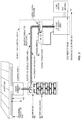
- FIG. 1 shows a grid-tied solar system
- FIG. 2 shows a solar system having a solar-charged battery
- FIG. 3 shows a remote-controlled solar combiner and DC disconnect
- FIG. 4 shows one implementation of the invention
- FIG. 5 shows a second implementation of the invention using a P-type MOSFET series switch
- FIG. 6 shows a second implementation using an N-type MOSFET series switch
- FIG. 7 shows an implementation using a series relay switch
- FIG. 8 shows an arrangement for switch sequence timing
- FIG. 1 shows a grid-tied solar energy system as described in the above-incorporated '822 patent.
- Solar combiner ( 700 ) combines selected strings of solar panels from array ( 1500 ) to produce a combined photovoltaic output current in photovoltaic output conductors ( 401 , 402 ) which, according to current National Electrical Code requirements, shall be contained in metallic conduit ( 400 ).
- the combined solar current is applied to DC to AC converter ( 2200 ) to generate a pure sinewave current at the grid frequency (e.g. 60 Hz) which is fed back to the grid through breaker ( 4040 ) to offset power consumption consumed from the grid.
- DC-to-AC converter is configured to disallow grid power from being synchronously rectified and fed back up the photovoltaic output conductors towards combiner ( 700 ), there is only one source of power, that is the solar array.
- FIG. 2 shows an alternative solar installation in which solar energy is used to charge a battery ( 500 ). Energy stored in the battery may be extracted later or at the same time as charging to be converted to AC power by DC to AC converter ( 1000 ).
- DC to AC converter ( 1000 ) has the capability to power loads directly and so can power a home not connected to the grid, or when the grid is in outage.
- Converter ( 1000 ) also preferably acts as a battery charge controller by monitoring battery state and controlling solar combiner ( 700 ) via the control cable to connect more or fewer solar strings through to charge the battery.
- FIG. 3 illustrates the principle of combiner ( 700 ).
- the connector ( 711 ) for Control port 1 carries current to the coils of relays ( 706 ), of which there is one per string to be combined.
- the return path for the current is through switch ( 709 ).
- Switch ( 709 ) may be located on the combiner and accessible for manual operation, or may be a microswitch which opens when the front panel of the combiner is opened. When switch ( 709 ) is opened, all relays ( 706 ) and ( 707 ) are de-energized so that no string is connected through either to photovoltaic output 1 ( 722 ) or output 2 ( 721 ).
- the same effect may be had by interrupting the relay coil return path at the converter, or by controlling all relays to be de-energized. If the converter supplies power to the relay coils only when operating, then switching off the converter will automatically de-energize the relays and thus de-energize the associated photovoltaic output circuit ( 721 or 722 ).
- the means to prevent the photovoltaic output circuit being energized by the solar panels is provided by the remote-controlled solar combiner ( 700 ).
- the battery can still energize the photovoltaic output circuit conductors leading from the battery ( 500 ) to the combiner ( 700 ).
- additional components may be associated with the battery according to this invention, as shown in FIG. 4 .
- FIG. 4 shows a battery ( 501 ) contained in a battery enclosure ( 500 ).
- the battery enclosure ( 500 ) shall be vented to the outside air to prevent build up of hydrogen and battery odors.
- the connection from the battery to the load (DC to AC converter 1000 ) is through circuit breaker ( 551 ) as opposed to the alternative of fuses ( 550 ) shown in FIG. 2 .
- Either overcurrent protection method is acceptable, but the use of a circuit breaker provides a more convenient manual means to disconnect the battery from the inverter than unplugging fuses.
- breaker ( 551 ) may be two-pole breaker (as illustrated), or may be a single pole breaker if one side of the DC is grounded. Fuses ( 550 ) are still used in FIG. 4 as in FIG. 2 to protect the DC conductors ( 401 , 402 ) from overcurrent.
- diode ( 553 ) The first additional component that is evident in FIG. 4 compared to FIG. 2 is diode ( 553 ). This prevents reverse current flow from the battery towards combiner ( 700 ) should anything unintentionally contact conductors ( 401 , 402 ). Thus in principle, operating the remote disconnect facility of combiner ( 700 ) by means of appropriate signals on control cable ( 570 ) now de-energizes conductors ( 401 , 402 ) from both power sources, the solar array and the battery. Moreover, diode ( 553 ) if properly functioning ensures that fuses ( 55 ) should never blow, as reverse current cannot flow. However, semiconductor devices are known to fail in the short circuit condition and thus cannot be totally relied upon for overcurrent protection; hence fuses ( 550 ) are still included.
- Switch ( 552 ) can for example comprise a pair of normally closed relay contacts that apply a short circuit between conductors ( 401 , 402 ) unless the relay is energized to open the contacts.
- the same control signal that energizes the relays in combiner ( 700 ) to apply power to conductors ( 401 , 402 ) can be used to energize switch ( 552 ) to open its contacts.
- combiner 700 will not supply array power to conductors ( 401 , 402 ) and control switch ( 552 ) will remain closed. If diode ( 553 ) has failed short circuit, one or both of fuses ( 550 ) will blow when switch ( 552 ) is closed. Since this only happens when diode ( 553 ) is faulty, and that is expected to be a rare event, it is not expected that a high incidence of fuses ( 550 ) blowing will be encountered in service. Moreover, since diode ( 553 ) failing and fuses ( 550 ) blowing will always occur together, they can be packaged together as a replaceable sub-assembly.
- controlled crowbar switch ( 552 ) is shown located at the battery. However, it could alternatively be located in solar combiner ( 700 ), or in both places.
- Diode ( 553 ) passes all the of the solar array power, perhaps 40 amps at 125 volts in the case of a 5 KW system.
- the voltage drop of the diode lies in the 0.6 to 1 volt range, which represents a fractional power loss of 0.5% to 0.8%, but more significantly, involves heat dissipation of between 24 and 40 watts.
- an alternative to using diode ( 553 ) alone is to use a MOSFET transistor having an intrinsic drain-source diode, the transistor being turned on to short out the diode drop under normal circumstances. Such a circuit is shown in FIG. 5 as second implementation.
- P-type MOSFET 553 intrinsically comprises the diode 553 of FIG. 4 .
- switch 552 is now a SPDT relay that applies the negative of the battery through potential divided R 1 ,R 2 to the gate of MOSFET 553 when switch 552 is activated to remove the short from between conductors ( 401 , 402 ).
- This turns MOSFET 553 on, thereby passing current from the solar array to the battery with a voltage drop less than that of the diode alone.
- 10 P-type MOSFET chips type FDMS86263P in parallel will provide an ON resistance of about 5 milliohms, giving 200 mV drop at 40 amps, and 8 watts of heat to be dissipated.
- FIG. 6 shows a version of the invention using an N-type MOSFET as the series switch.
- N-type MOSFET As the series switch.
- FIG. 6 it was merely necessary to interchange the polarity of the battery terminals and associated connections to the array and the inverter, and to select an N-type MOSFET for series switch 553 , the intrinsic diode of which is now facing the other way.
- Three N-type MOSFETs type FDP075N15A in parallel now provide an ON resistance of about 2.5 milliohms and thus about 100 mv voltage drop at 40 amps, reducing the heat loss to 4 watts.
- a P-type series MOSFET switch can be placed in the positive lead as per FIG. 5
- an N-type series MOSFET switch is used in the negative lead, as per FIG. 6 .
- the high-current relay ( 554 ) can be of a lower cost type providing it is not required to open with current flowing through it. This may be ensured by timing the solar disconnect within solar combiner ( 700 ) to occur before relay ( 554 ) is commanded to open. Another timing requirement is that switch ( 552 ) should not close before relay ( 554 ) is open, and it must open before relay ( 554 ) closes. A control circuit is therefore required to ensure these relative timings.
- An advantage of the simple diode circuit of FIG. 5 is that no such timing constraints are required.
- the timing constraints are likewise simple, as MOSFET series switch ( 553 ) is synchronized to switch ( 552 ) by the Normally Open contact of switch ( 552 ). However, for FIG. 7 , more discussion of how to arrange for proper timing is required, which is explained with the aid of FIG. 8 .
- crowbar switch 552 is a high current MOSFET (Q 1 ).
- Q 1 high current MOSFET
- the requirements on Q 1 do not include very low loss resistance, unlike if it was used as a series switch. The requirement is merely that it should pass enough current to blow one of fuses ( 550 ) should it inadvertently be placed into conduction with switch 554 closed. The latter condition however is to be avoided by ensuring proper timing of the opening of switch ( 554 ) before switch ( 552 ) closes. Moreover, switch ( 554 ) should not open before switches 706 or 707 (as also depicted in FIG. 3 ) have opened.
- FIG. 8 shows that switches 706 or 707 (also of FIG. 3 ) are controlled by a relay driver ( 1100 ) which is envisaged to be part of inverter ( 1000 ), as described in the above-incorporated '822 patent.
- a relay driver output for each relay ( 706 or 707 ) of remote controlled solar combiner ( 700 ), which are controlled as a means to control battery charging.
- FIG. 8 is more general however than the envisaged solar application.
- FIG. 8 presumes that there is a first power source on the left feeding current to a second power source on the right, and controlled switches ( 706 or 707 ) may be controlled by disabling the relevant relay driver ( 1100 ) to interrupt the current flow from the first power source to the second power source. It is also presumed that any steps necessary to shield switches ( 706 or 707 ) from sparking upon sudden current interruption have been taken at power source 1 end.
- switches ( 706 or 707 ) are opened by relay driver ( 1100 ) removing the ground return for power supply ( 1100 ) to switches ( 706 or 707 ) while leaving the power supply and ground connections to high current relay ( 554 ) intact.
- switches ( 706 or 707 ) may be controlled to open while leaving high-current relay ( 554 ) contacts closed, and then controlling power supply ( 1100 ) to be OFF removes the drive to the coil of high current relay ( 554 ) so that its contacts open afterwards.
- high current relay ( 554 ) has little electrical stress, as it only ever opens and closes with zero current through its contacts.
- choosing high current relay ( 554 ) to be a SPDT relay allows the 235 normally closed contact to function as crowbar switch ( 552 ). Since the relay cannot mechanically close the normally closed contact unless the normally open contact is opened, the probability of both contacts being closed and blowing fuses ( 550 ) is remote.
- an inverter uses a floating DC input of 120 volts nominal, and grounds the negative and the positive of the floating source alternately at 60 Hz.
- the positive is grounded, the negative conductor of source 1 and 2 will be at ⁇ 120 volts nominal.
- switch ( 554 ) it is not sufficient to open the positive connection between source 1 and source 2 using switch ( 554 ) to ensure de-energization of the conductors; however, when the inverter as described in the '882 patent is switched off, not only are neither the positive nor the negative of the source not grounded, but also the neutral output of the inverter is opened, as well as the live output, thus floating the inverter circuitry.
- part of the de-energization of conductors ( 401 , 402 ) in such an installation comprises switching off the inverter, which also switches off the power supply ( 1100 ) which is incorporated within it.
- a second high current relay similar to relay ( 554 ) can be placed in the negative lead so that both positive and negative conductors leading from the first power to the second power source are broken at both ends.
- a transistor such as a MOSFET to function as crowbar switch ( 522 ) if it proves difficult to obtain SPDT relays for switch ( 554 ).
- a double pole relay ( 554 ) to open both the negative and positive conductors, and being also specially designed to apply a short circuit between the moving contacts when in the de-energized condition.
- the latter may be done internally so that no external connections are required to the normally closed contacts.
- a MOSFET transistor is used as crowbar switch ( 552 )
- the switch must be ON when everything else is OFF. Therefore the voltage necessary to turn the gate on must come from an internal source, such as a charged capacitor. It is only necessary for the charge to be sufficient to keep the transistor operating as a crowbar switch long enough to blow fuses 550 if one of the series switches ( 554 ) has failed to open or diode ( 553 ) of FIG. 4 has failed short circuit.
- fuses ( 55 ) may be replaced by a suitable circuit breaker or any other suitable overcurrent protection device. Resettable circuit breakers are most appropriate if frequent tripping is expected, but if the not the case, then fuses may be the lower cost choice.
Abstract
Description
Claims (14)
Priority Applications (1)
| Application Number | Priority Date | Filing Date | Title |
|---|---|---|---|
| US15/197,431 US11196272B2 (en) | 2016-06-29 | 2016-06-29 | Rapid de-energization of DC conductors with a power source at both ends |
Applications Claiming Priority (1)
| Application Number | Priority Date | Filing Date | Title |
|---|---|---|---|
| US15/197,431 US11196272B2 (en) | 2016-06-29 | 2016-06-29 | Rapid de-energization of DC conductors with a power source at both ends |
Publications (2)
| Publication Number | Publication Date |
|---|---|
| US20180006601A1 US20180006601A1 (en) | 2018-01-04 |
| US11196272B2 true US11196272B2 (en) | 2021-12-07 |
Family
ID=60807215
Family Applications (1)
| Application Number | Title | Priority Date | Filing Date |
|---|---|---|---|
| US15/197,431 Active US11196272B2 (en) | 2016-06-29 | 2016-06-29 | Rapid de-energization of DC conductors with a power source at both ends |
Country Status (1)
| Country | Link |
|---|---|
| US (1) | US11196272B2 (en) |
Families Citing this family (11)
| Publication number | Priority date | Publication date | Assignee | Title |
|---|---|---|---|---|
| US11460488B2 (en) | 2017-08-14 | 2022-10-04 | Koolbridge Solar, Inc. | AC electrical power measurements |
| US8937822B2 (en) | 2011-05-08 | 2015-01-20 | Paul Wilkinson Dent | Solar energy conversion and utilization system |
| US10090777B2 (en) | 2011-05-08 | 2018-10-02 | Koolbridge Solar, Inc. | Inverter with independent current and voltage controlled outputs |
| US11901810B2 (en) | 2011-05-08 | 2024-02-13 | Koolbridge Solar, Inc. | Adaptive electrical power distribution panel |
| US10033302B2 (en) | 2014-08-29 | 2018-07-24 | Koolbridge Solar, Inc. | Rotary solar converter |
| JP6450403B2 (en) * | 2015-01-28 | 2019-01-09 | 京セラ株式会社 | Power control apparatus, power control system, and power control method |
| US10148093B2 (en) | 2015-06-16 | 2018-12-04 | Koolbridge Solar, Inc. | Inter coupling of microinverters |
| US11228171B2 (en) | 2017-08-14 | 2022-01-18 | Koolbridge Solar, Inc. | Overcurrent trip coordination between inverter and circuit breakers |
| US10250162B2 (en) | 2017-08-14 | 2019-04-02 | Koolbridge Solar, Inc. | DC bias prevention in transformerless inverters |
| CN109109341B (en) * | 2018-10-23 | 2021-02-02 | 株洲时代新材料科技股份有限公司 | Preparation method of wind power blade |
| CN115580020A (en) * | 2022-10-24 | 2023-01-06 | 徐州建机工程机械有限公司 | Electric equipment for tower crane trolley and remote control method |
Citations (105)
| Publication number | Priority date | Publication date | Assignee | Title |
|---|---|---|---|---|
| US3340457A (en) | 1964-11-24 | 1967-09-05 | Allis Louis Co | Static inverter circuit |
| US3805141A (en) | 1973-01-08 | 1974-04-16 | United Aircraft Corp | Bimodal inverter |
| GB1433402A (en) | 1973-04-11 | 1976-04-28 | Hore D L | Variable reactors and transformers |
| US3958174A (en) | 1975-04-16 | 1976-05-18 | Borg-Warner Corporation | Modulated induction generator |
| US4084220A (en) | 1976-03-09 | 1978-04-11 | Mitsubishi Denki Kabushiki Kaisha | Power converter |
| US4180853A (en) | 1978-08-23 | 1979-12-25 | United Technologies Corporation | Two-stage commutation circuit for an inverter |
| US4204268A (en) | 1978-08-02 | 1980-05-20 | United Technologies Corporation | Auxiliary commutation circuit for an inverter |
| US4306183A (en) * | 1979-03-14 | 1981-12-15 | Lucas Industries Limited | Voltage regulation circuit for a solar cell charging system |
| US4320449A (en) | 1962-03-22 | 1982-03-16 | Westinghouse Electric Corp. | Control circuit |
| US4626764A (en) * | 1983-09-02 | 1986-12-02 | The United States Of America As Represented By The Secretary Of The Navy | Photovoltaic battery charge controller |
| US4803611A (en) | 1987-02-12 | 1989-02-07 | Mitsubishi Denki Kabushiki Kaisha | Apparatus for correcting DC component of output voltage in inverter |
| US4882120A (en) | 1988-12-16 | 1989-11-21 | Sundstrand Corporation | DC content control for an inverter |
| US5153497A (en) * | 1991-08-28 | 1992-10-06 | Eiden Glenn E | Circuit for regulating charging of a storage battery by a photovoltaic array |
| US5226077A (en) | 1992-03-02 | 1993-07-06 | Acs Communications, Inc. | Headset amplifier with automatic log on/log off detection |
| US5270636A (en) * | 1992-02-18 | 1993-12-14 | Lafferty Donald L | Regulating control circuit for photovoltaic source employing switches, energy storage, and pulse width modulation controller |
| US5373433A (en) | 1992-05-05 | 1994-12-13 | Trace Engineering | Power inverter for generating voltage regulated sine wave replica |
| US5424894A (en) | 1992-11-24 | 1995-06-13 | Briscall; W. Brian | Electrical line-fault detector and circuit breaker device |
| US5479086A (en) | 1990-04-30 | 1995-12-26 | Fraunhofer Gesellschaft Zur Forderung Der Angewandten Forschung E.V. | Process and device for reducing the inrush current when powering aninductive load |
| US5625276A (en) | 1994-09-14 | 1997-04-29 | Coleman Powermate, Inc. | Controller for permanent magnet generator |
| US5714869A (en) * | 1995-10-26 | 1998-02-03 | Canon Kabushiki Kaisha | Power source apparatus with battery and overcharge protection circuit |
| US5726505A (en) * | 1995-01-13 | 1998-03-10 | Omron Corporation | Device to prevent reverse current flow, rectifier device and solar generator system |
| US5930128A (en) | 1998-04-02 | 1999-07-27 | Ericsson Inc. | Power waveform synthesis using bilateral devices |
| US5991645A (en) | 1992-03-02 | 1999-11-23 | Gn Netcom, Inc. | Wireless telephone headset system with automatic log on/log off detection |
| US6051954A (en) * | 1997-05-30 | 2000-04-18 | Canon Kabushiki Kaisha | Charge control apparatus |
| US6154379A (en) | 1998-07-16 | 2000-11-28 | Tdk Corporation | Electric power conversion device |
| US20020047455A1 (en) | 2000-02-24 | 2002-04-25 | Hamilton Sundstrand Corporation | Induction motor/generator system |
| US20030094931A1 (en) * | 2001-11-19 | 2003-05-22 | Renyolds Robert Lee | Micro-solar insolation circuit |
| US20030094929A1 (en) | 2001-01-26 | 2003-05-22 | Pendell Larry Stuart | Induction generator system and method |
| US20030179063A1 (en) | 2000-03-07 | 2003-09-25 | Norbert Preusse | Current transformer for a compensating current sensor |
| US20040100149A1 (en) | 2002-11-22 | 2004-05-27 | Jih-Sheng Lai | Topologies for multiple energy sources |
| US20050001598A1 (en) | 2003-07-02 | 2005-01-06 | Mes International, Inc. | Electrical power generation system and method |
| US20050056021A1 (en) | 2003-09-12 | 2005-03-17 | Mes International, Inc. | Multi-spool turbogenerator system and control method |
| US20050073292A1 (en) | 2003-10-01 | 2005-04-07 | Hastings Jerome K. | System and method for current sensing using anti-differential, error correcting current sensing |
| US20050180083A1 (en) | 2002-04-26 | 2005-08-18 | Toshiba Matsushita Display Technology Co., Ltd. | Drive circuit for el display panel |
| US20060158037A1 (en) | 2005-01-18 | 2006-07-20 | Danley Douglas R | Fully integrated power storage and supply appliance with power uploading capability |
| US7082040B2 (en) | 1993-03-29 | 2006-07-25 | Eaton Power Quality Corporation | Power factor corrected UPS with improved connection of battery to neutral |
| US20070095062A1 (en) | 2003-07-01 | 2007-05-03 | Tiax Llc | Capacitive position sensor and sensing methodology |
| US20070292724A1 (en) | 2006-06-16 | 2007-12-20 | Gilchrist Ian T | System and method to start a fuel cell stack during a cold-start condition |
| US7474016B2 (en) | 2006-05-23 | 2009-01-06 | Continental Automotive Systems Us, Inc. | System and method for responding to abrupt load changes on a power system |
| US20090015071A1 (en) * | 2005-02-25 | 2009-01-15 | Mitsubishi Electric Corporation | Power conversion apparatus |
| CN101350569A (en) | 2008-09-03 | 2009-01-21 | 深圳职业技术学院 | Topological structure for solar photovoltaic inverter |
| US20090161392A1 (en) | 2007-12-19 | 2009-06-25 | Hong Zhang | Dc component elimination at output voltage of pwm inverters |
| US20090184706A1 (en) | 2006-05-30 | 2009-07-23 | Koninklijke Philips Electronics N.V. | Sensor device with adaptive field compensation |
| US20090206666A1 (en) | 2007-12-04 | 2009-08-20 | Guy Sella | Distributed power harvesting systems using dc power sources |
| US20090207543A1 (en) * | 2008-02-14 | 2009-08-20 | Independent Power Systems, Inc. | System and method for fault detection and hazard prevention in photovoltaic source and output circuits |
| US20100064424A1 (en) * | 2008-09-18 | 2010-03-18 | Yen-Ta Hsu | Flush apparatus |
| US20100110742A1 (en) * | 2007-03-06 | 2010-05-06 | West Richard T | Bipolar dc to ac power converter with dc ground fault interrupt |
| US20110037600A1 (en) | 2009-08-17 | 2011-02-17 | Toru Takehara | Photovoltaic panel monitoring apparatus |
| US20110037602A1 (en) * | 2009-08-12 | 2011-02-17 | Wojciech Marek Chrosny | Method and apparatus for protecting energy generation facility from dangerous degree of tilt |
| US20110043160A1 (en) | 2009-08-21 | 2011-02-24 | Xantrex Technology Inc. | Ac connected modules with line frequency or voltage variation pattern for energy control |
| US20110090607A1 (en) | 2009-10-20 | 2011-04-21 | Luebke Charles J | String and system employing direct current electrical generating modules and a number of string protectors |
| US20110141644A1 (en) * | 2009-12-15 | 2011-06-16 | Hastings Jerome K | Direct current arc fault circuit interrupter, direct current arc fault detector, noise blanking circuit for a direct current arc fault circuit interrupter, and method of detecting arc faults |
| US20110140520A1 (en) | 2009-12-16 | 2011-06-16 | Sung-Im Lee | Energy storage system and method of controlling the same |
| US20110285354A1 (en) * | 2010-05-23 | 2011-11-24 | Hiroshi Iwasa | Rechargeable battery controlling circuit, rechargeable battery controlling device, independent power system and battery pack |
| US20110301772A1 (en) | 2010-06-07 | 2011-12-08 | Zuercher Joseph C | Protection, monitoring or indication apparatus for a direct current electrical generating apparatus or a plurality of strings |
| US20120007459A1 (en) | 2010-07-09 | 2012-01-12 | Nikhil Mondal | Rotating Electric Machine for Generating a Constant Frequency AC Power Supply from a Variable Speed Primemover |
| US20120048325A1 (en) | 2010-08-24 | 2012-03-01 | Sanyo Electric Co., Ltd. | Photovoltaic power generating device, and controlling method |
| US20120049637A1 (en) | 2010-12-21 | 2012-03-01 | Ralph Teichmann | Methods and Systems for Operating a Power Generation System |
| US20120112557A1 (en) | 2010-10-09 | 2012-05-10 | Sager Brian M | Solar Panel with Reconfigurable Interconnections |
| US8185762B1 (en) * | 2008-05-28 | 2012-05-22 | Google Inc. | Low power display |
| CN202444440U (en) | 2012-02-27 | 2012-09-19 | 无锡联动太阳能科技有限公司 | Bridgeless inverter circuit and solar bridgeless inverter |
| US20120242145A1 (en) | 2008-07-30 | 2012-09-27 | GENERAC POWER SYSTEMS, INC. a Wisconsin Corporation | Automatic transfer switch |
| WO2012140495A2 (en) | 2011-04-11 | 2012-10-18 | Gerald Goche | Integrated motor and generator |
| US20120281444A1 (en) | 2011-05-08 | 2012-11-08 | Paul Wilkinson Dent | Solar energy conversion and utilization system |
| EP2544354A2 (en) | 2011-07-08 | 2013-01-09 | Infineon Technologies AG | Power converter circuit with AC output |
| US20130057997A1 (en) | 2011-09-05 | 2013-03-07 | Koolbridge Inc. | Potential Arc Fault Detection and Suppression |
| US20130058144A1 (en) | 2011-09-01 | 2013-03-07 | Kabushiki Kaisha Yaskawa Denki | Power conversion apparatus |
| US20130070494A1 (en) | 2007-05-17 | 2013-03-21 | Enphase Energy, Inc. | Photovoltaic module-mounted ac inverter |
| US20130181703A1 (en) | 2010-03-26 | 2013-07-18 | Infineon Technologies Ag | Sensor Package and Method for Producing a Sensor Package |
| US20130181655A1 (en) * | 2010-10-07 | 2013-07-18 | Sony Corporation | Power control device, power control method, and feed system |
| US20130245614A1 (en) | 2012-03-13 | 2013-09-19 | Terumo Kabushiki Kaisha | Fault monitor for fault tolerant implantable pump |
| US20130320929A1 (en) | 2012-05-31 | 2013-12-05 | Walker Solar Products, LLC | Self-contained power supply |
| US20140001864A1 (en) * | 2012-06-29 | 2014-01-02 | Prasanna S. Nirantare | System and method for connection of photovoltaic arrays in series and parallel arrangements |
| EP2698894A2 (en) | 2012-08-15 | 2014-02-19 | General Electric Company | Alternative Power Converter System |
| US20140062206A1 (en) * | 2012-08-29 | 2014-03-06 | Robert L. Bryson | Low Voltage Solar Electric Energy Distribution |
| US20140119072A1 (en) * | 2011-07-04 | 2014-05-01 | Sma Solar Technology Ag | Method and System for Detecting an Arc Fault in a Photovoltaic Power System |
| US20140153303A1 (en) | 2012-11-30 | 2014-06-05 | SunEdison Microinverter Products LLC | Solar module having a back plane integrated inverter |
| US20140266289A1 (en) | 2013-03-15 | 2014-09-18 | Technology Research Corporation | Interface for renewable energy system |
| US20140301003A1 (en) * | 2011-08-19 | 2014-10-09 | Phoenix Contact Gmbh & Co. Kg | Socket for a Solar Panel with a Protective Circuit |
| US8859884B2 (en) * | 2009-10-19 | 2014-10-14 | Helios Focus Llc | Solar photovoltaic module safety shutdown system |
| US20150008748A1 (en) | 2012-01-17 | 2015-01-08 | Infineon Technologies Austria Ag | Power Converter Circuit, Power Supply System and Method |
| US20150217656A1 (en) | 2014-01-31 | 2015-08-06 | Ford Global Technologies, Llc | Portable EV Energy Transfer Apparatus and Method |
| US20150229131A1 (en) * | 2014-02-13 | 2015-08-13 | Nextronex, Inc. | Grid tie solar inverter system with storage |
| US20150270731A1 (en) * | 2012-09-03 | 2015-09-24 | Robert Bosch (SEA)PET. LTD. | Topology and control strategy for hybrid storage systems |
| US20150309075A1 (en) * | 2013-08-28 | 2015-10-29 | San Diego Gas & Electric company c/o Sempra Energy | Interconnection meter socket adapters |
| US20150340868A1 (en) * | 2014-05-25 | 2015-11-26 | Sunpower Corporation | Alternative source module array characterization |
| US20150349708A1 (en) * | 2013-04-13 | 2015-12-03 | Solexel, Inc. | Solar photovoltaic module power control and status monitoring system utilizing laminate-embedded remote access module switch |
| US20160006392A1 (en) * | 2013-02-11 | 2016-01-07 | Phoenix Contact Gmbh & Co. Kg | Safe Photovoltaic System |
| US20160036235A1 (en) * | 2014-07-30 | 2016-02-04 | Robert Getsla | Safety Shutdown System for Photovoltaic Power Generators |
| US20160065090A1 (en) | 2014-08-29 | 2016-03-03 | Paul Wilkinson Dent | Rotary solar converter |
| US20160141846A1 (en) * | 2014-11-13 | 2016-05-19 | Solarcity Corporation | Systems for backfeeding photovoltaic arrays through main breaker boxes |
| US20160181752A1 (en) * | 2013-08-28 | 2016-06-23 | San Diego Gas & Electric company c/o Sempra Energy | Interconnect socket adapter for adapting one or more power sources and power sinks |
| US20160211797A1 (en) * | 2015-01-16 | 2016-07-21 | Delta Electronics, Inc. | Photovoltaic power generation system and shut-down device |
| US20160224083A1 (en) | 2015-01-29 | 2016-08-04 | Paul Wilkinson Dent | Addressable Electrical Outlets |
| US20160226560A1 (en) | 2015-01-29 | 2016-08-04 | Paul Wilkinson Dent | Smart Appliances |
| US20160261226A1 (en) * | 2015-03-06 | 2016-09-08 | Instant Solar LLC | Portable solar power generation devices for permanent or temporary installations and methods thereof |
| US20160276837A1 (en) | 2013-11-07 | 2016-09-22 | The University Of North Carolina At Charlotte | Control system for electrical energy outputting device |
| US9455645B1 (en) | 2013-03-13 | 2016-09-27 | The Florida State University Research Foundation, Inc. | System and method for leakage current suppression in a photovoltaic cascaded multilevel inverter |
| US20160322827A1 (en) * | 2015-04-28 | 2016-11-03 | First Solar, Inc. | Photovoltaic dc power distribution system |
| WO2016204830A1 (en) | 2015-06-16 | 2016-12-22 | Koolbridge Solar, Inc. | Inter coupling of microinverters |
| US20170070081A1 (en) * | 2014-03-06 | 2017-03-09 | Robert Bosch Gmbh | Hybrid storage system |
| US20170155274A1 (en) * | 2014-03-03 | 2017-06-01 | Robert Bosch Gmbh | Topology and control strategy for hybrid storage systems |
| US9812869B2 (en) * | 2016-03-21 | 2017-11-07 | Solarcity Corporation | Rapid shutdown and safety disconnect for hybrid PV systems |
| US20180026550A1 (en) | 2011-05-08 | 2018-01-25 | Paul Wilkinson Dent | Inverter with independent current and voltage controlled outputs |
| US20180062015A1 (en) * | 2015-03-09 | 2018-03-01 | Suzhou Talesun Solar Technologies, Co., Ltd. | Intelligent solar photovoltaic module circuit and control/protection method therefor |
-
2016
- 2016-06-29 US US15/197,431 patent/US11196272B2/en active Active
Patent Citations (118)
| Publication number | Priority date | Publication date | Assignee | Title |
|---|---|---|---|---|
| US4320449A (en) | 1962-03-22 | 1982-03-16 | Westinghouse Electric Corp. | Control circuit |
| US3340457A (en) | 1964-11-24 | 1967-09-05 | Allis Louis Co | Static inverter circuit |
| US3805141A (en) | 1973-01-08 | 1974-04-16 | United Aircraft Corp | Bimodal inverter |
| GB1433402A (en) | 1973-04-11 | 1976-04-28 | Hore D L | Variable reactors and transformers |
| US3958174A (en) | 1975-04-16 | 1976-05-18 | Borg-Warner Corporation | Modulated induction generator |
| US4084220A (en) | 1976-03-09 | 1978-04-11 | Mitsubishi Denki Kabushiki Kaisha | Power converter |
| US4204268A (en) | 1978-08-02 | 1980-05-20 | United Technologies Corporation | Auxiliary commutation circuit for an inverter |
| US4180853A (en) | 1978-08-23 | 1979-12-25 | United Technologies Corporation | Two-stage commutation circuit for an inverter |
| US4306183A (en) * | 1979-03-14 | 1981-12-15 | Lucas Industries Limited | Voltage regulation circuit for a solar cell charging system |
| US4626764A (en) * | 1983-09-02 | 1986-12-02 | The United States Of America As Represented By The Secretary Of The Navy | Photovoltaic battery charge controller |
| US4803611A (en) | 1987-02-12 | 1989-02-07 | Mitsubishi Denki Kabushiki Kaisha | Apparatus for correcting DC component of output voltage in inverter |
| US4882120A (en) | 1988-12-16 | 1989-11-21 | Sundstrand Corporation | DC content control for an inverter |
| US4882120B1 (en) | 1988-12-16 | 1991-05-21 | Sunstrand Corp | |
| US5479086A (en) | 1990-04-30 | 1995-12-26 | Fraunhofer Gesellschaft Zur Forderung Der Angewandten Forschung E.V. | Process and device for reducing the inrush current when powering aninductive load |
| US5153497A (en) * | 1991-08-28 | 1992-10-06 | Eiden Glenn E | Circuit for regulating charging of a storage battery by a photovoltaic array |
| US5270636A (en) * | 1992-02-18 | 1993-12-14 | Lafferty Donald L | Regulating control circuit for photovoltaic source employing switches, energy storage, and pulse width modulation controller |
| US5226077A (en) | 1992-03-02 | 1993-07-06 | Acs Communications, Inc. | Headset amplifier with automatic log on/log off detection |
| US5991645A (en) | 1992-03-02 | 1999-11-23 | Gn Netcom, Inc. | Wireless telephone headset system with automatic log on/log off detection |
| US5373433A (en) | 1992-05-05 | 1994-12-13 | Trace Engineering | Power inverter for generating voltage regulated sine wave replica |
| US5424894A (en) | 1992-11-24 | 1995-06-13 | Briscall; W. Brian | Electrical line-fault detector and circuit breaker device |
| US7082040B2 (en) | 1993-03-29 | 2006-07-25 | Eaton Power Quality Corporation | Power factor corrected UPS with improved connection of battery to neutral |
| US5625276A (en) | 1994-09-14 | 1997-04-29 | Coleman Powermate, Inc. | Controller for permanent magnet generator |
| US5726505A (en) * | 1995-01-13 | 1998-03-10 | Omron Corporation | Device to prevent reverse current flow, rectifier device and solar generator system |
| US5714869A (en) * | 1995-10-26 | 1998-02-03 | Canon Kabushiki Kaisha | Power source apparatus with battery and overcharge protection circuit |
| US6051954A (en) * | 1997-05-30 | 2000-04-18 | Canon Kabushiki Kaisha | Charge control apparatus |
| US5930128A (en) | 1998-04-02 | 1999-07-27 | Ericsson Inc. | Power waveform synthesis using bilateral devices |
| US6154379A (en) | 1998-07-16 | 2000-11-28 | Tdk Corporation | Electric power conversion device |
| US20020047455A1 (en) | 2000-02-24 | 2002-04-25 | Hamilton Sundstrand Corporation | Induction motor/generator system |
| US20030179063A1 (en) | 2000-03-07 | 2003-09-25 | Norbert Preusse | Current transformer for a compensating current sensor |
| US7057485B2 (en) | 2000-03-07 | 2006-06-06 | Vacuumschmelze Gmbh & Co. Kg | Current transformer for a compensating current sensor |
| US20030094929A1 (en) | 2001-01-26 | 2003-05-22 | Pendell Larry Stuart | Induction generator system and method |
| US20030094931A1 (en) * | 2001-11-19 | 2003-05-22 | Renyolds Robert Lee | Micro-solar insolation circuit |
| US20050180083A1 (en) | 2002-04-26 | 2005-08-18 | Toshiba Matsushita Display Technology Co., Ltd. | Drive circuit for el display panel |
| US20040100149A1 (en) | 2002-11-22 | 2004-05-27 | Jih-Sheng Lai | Topologies for multiple energy sources |
| US7138730B2 (en) | 2002-11-22 | 2006-11-21 | Virginia Tech Intellectual Properties, Inc. | Topologies for multiple energy sources |
| US20070095062A1 (en) | 2003-07-01 | 2007-05-03 | Tiax Llc | Capacitive position sensor and sensing methodology |
| US20050001598A1 (en) | 2003-07-02 | 2005-01-06 | Mes International, Inc. | Electrical power generation system and method |
| US20050056021A1 (en) | 2003-09-12 | 2005-03-17 | Mes International, Inc. | Multi-spool turbogenerator system and control method |
| US20050073292A1 (en) | 2003-10-01 | 2005-04-07 | Hastings Jerome K. | System and method for current sensing using anti-differential, error correcting current sensing |
| US20060158037A1 (en) | 2005-01-18 | 2006-07-20 | Danley Douglas R | Fully integrated power storage and supply appliance with power uploading capability |
| US20090015071A1 (en) * | 2005-02-25 | 2009-01-15 | Mitsubishi Electric Corporation | Power conversion apparatus |
| US7474016B2 (en) | 2006-05-23 | 2009-01-06 | Continental Automotive Systems Us, Inc. | System and method for responding to abrupt load changes on a power system |
| US20090184706A1 (en) | 2006-05-30 | 2009-07-23 | Koninklijke Philips Electronics N.V. | Sensor device with adaptive field compensation |
| US20070292724A1 (en) | 2006-06-16 | 2007-12-20 | Gilchrist Ian T | System and method to start a fuel cell stack during a cold-start condition |
| US20100110742A1 (en) * | 2007-03-06 | 2010-05-06 | West Richard T | Bipolar dc to ac power converter with dc ground fault interrupt |
| US20130070494A1 (en) | 2007-05-17 | 2013-03-21 | Enphase Energy, Inc. | Photovoltaic module-mounted ac inverter |
| US20090206666A1 (en) | 2007-12-04 | 2009-08-20 | Guy Sella | Distributed power harvesting systems using dc power sources |
| US20090161392A1 (en) | 2007-12-19 | 2009-06-25 | Hong Zhang | Dc component elimination at output voltage of pwm inverters |
| US20090207543A1 (en) * | 2008-02-14 | 2009-08-20 | Independent Power Systems, Inc. | System and method for fault detection and hazard prevention in photovoltaic source and output circuits |
| US8185762B1 (en) * | 2008-05-28 | 2012-05-22 | Google Inc. | Low power display |
| US20120242145A1 (en) | 2008-07-30 | 2012-09-27 | GENERAC POWER SYSTEMS, INC. a Wisconsin Corporation | Automatic transfer switch |
| CN101350569A (en) | 2008-09-03 | 2009-01-21 | 深圳职业技术学院 | Topological structure for solar photovoltaic inverter |
| US20100064424A1 (en) * | 2008-09-18 | 2010-03-18 | Yen-Ta Hsu | Flush apparatus |
| US20110037602A1 (en) * | 2009-08-12 | 2011-02-17 | Wojciech Marek Chrosny | Method and apparatus for protecting energy generation facility from dangerous degree of tilt |
| US20110037600A1 (en) | 2009-08-17 | 2011-02-17 | Toru Takehara | Photovoltaic panel monitoring apparatus |
| US20110043160A1 (en) | 2009-08-21 | 2011-02-24 | Xantrex Technology Inc. | Ac connected modules with line frequency or voltage variation pattern for energy control |
| US8859884B2 (en) * | 2009-10-19 | 2014-10-14 | Helios Focus Llc | Solar photovoltaic module safety shutdown system |
| US20110090607A1 (en) | 2009-10-20 | 2011-04-21 | Luebke Charles J | String and system employing direct current electrical generating modules and a number of string protectors |
| US20110141644A1 (en) * | 2009-12-15 | 2011-06-16 | Hastings Jerome K | Direct current arc fault circuit interrupter, direct current arc fault detector, noise blanking circuit for a direct current arc fault circuit interrupter, and method of detecting arc faults |
| US20110140520A1 (en) | 2009-12-16 | 2011-06-16 | Sung-Im Lee | Energy storage system and method of controlling the same |
| US20130181703A1 (en) | 2010-03-26 | 2013-07-18 | Infineon Technologies Ag | Sensor Package and Method for Producing a Sensor Package |
| US20110285354A1 (en) * | 2010-05-23 | 2011-11-24 | Hiroshi Iwasa | Rechargeable battery controlling circuit, rechargeable battery controlling device, independent power system and battery pack |
| US20110301772A1 (en) | 2010-06-07 | 2011-12-08 | Zuercher Joseph C | Protection, monitoring or indication apparatus for a direct current electrical generating apparatus or a plurality of strings |
| US20120007459A1 (en) | 2010-07-09 | 2012-01-12 | Nikhil Mondal | Rotating Electric Machine for Generating a Constant Frequency AC Power Supply from a Variable Speed Primemover |
| US20120048325A1 (en) | 2010-08-24 | 2012-03-01 | Sanyo Electric Co., Ltd. | Photovoltaic power generating device, and controlling method |
| US20130181655A1 (en) * | 2010-10-07 | 2013-07-18 | Sony Corporation | Power control device, power control method, and feed system |
| US20120112557A1 (en) | 2010-10-09 | 2012-05-10 | Sager Brian M | Solar Panel with Reconfigurable Interconnections |
| US20120049637A1 (en) | 2010-12-21 | 2012-03-01 | Ralph Teichmann | Methods and Systems for Operating a Power Generation System |
| WO2012140495A2 (en) | 2011-04-11 | 2012-10-18 | Gerald Goche | Integrated motor and generator |
| US8937822B2 (en) | 2011-05-08 | 2015-01-20 | Paul Wilkinson Dent | Solar energy conversion and utilization system |
| US20150318796A1 (en) | 2011-05-08 | 2015-11-05 | Paul Wilkinson Dent | Inverter inrush current limiting |
| US20150295413A1 (en) * | 2011-05-08 | 2015-10-15 | Paul Wilkinson Dent | Remotely controlled photovoltaic string combiner |
| US20120281444A1 (en) | 2011-05-08 | 2012-11-08 | Paul Wilkinson Dent | Solar energy conversion and utilization system |
| US20150288225A1 (en) | 2011-05-08 | 2015-10-08 | Paul Wilkinson Dent | Residential electrical energy installation |
| US20170346413A1 (en) | 2011-05-08 | 2017-11-30 | Paul Wilkinson Dent | Transformerless dc to ac converter |
| US20180026550A1 (en) | 2011-05-08 | 2018-01-25 | Paul Wilkinson Dent | Inverter with independent current and voltage controlled outputs |
| US20140084687A1 (en) | 2011-05-08 | 2014-03-27 | Paul Wilkinson Dent | Solar energy conversion and utilization system |
| US20140119072A1 (en) * | 2011-07-04 | 2014-05-01 | Sma Solar Technology Ag | Method and System for Detecting an Arc Fault in a Photovoltaic Power System |
| EP2544354A2 (en) | 2011-07-08 | 2013-01-09 | Infineon Technologies AG | Power converter circuit with AC output |
| US20140301003A1 (en) * | 2011-08-19 | 2014-10-09 | Phoenix Contact Gmbh & Co. Kg | Socket for a Solar Panel with a Protective Circuit |
| US20130058144A1 (en) | 2011-09-01 | 2013-03-07 | Kabushiki Kaisha Yaskawa Denki | Power conversion apparatus |
| US8891211B2 (en) | 2011-09-05 | 2014-11-18 | Paul Wilkinson Dent | Potential arc fault detection and suppression |
| US20150043110A1 (en) | 2011-09-05 | 2015-02-12 | Koolbridge Inc. | Potential Arc Fault Detection and Suppression |
| US20130057997A1 (en) | 2011-09-05 | 2013-03-07 | Koolbridge Inc. | Potential Arc Fault Detection and Suppression |
| US20150008748A1 (en) | 2012-01-17 | 2015-01-08 | Infineon Technologies Austria Ag | Power Converter Circuit, Power Supply System and Method |
| CN202444440U (en) | 2012-02-27 | 2012-09-19 | 无锡联动太阳能科技有限公司 | Bridgeless inverter circuit and solar bridgeless inverter |
| US20130245614A1 (en) | 2012-03-13 | 2013-09-19 | Terumo Kabushiki Kaisha | Fault monitor for fault tolerant implantable pump |
| US20130320929A1 (en) | 2012-05-31 | 2013-12-05 | Walker Solar Products, LLC | Self-contained power supply |
| US20140001864A1 (en) * | 2012-06-29 | 2014-01-02 | Prasanna S. Nirantare | System and method for connection of photovoltaic arrays in series and parallel arrangements |
| EP2698894A2 (en) | 2012-08-15 | 2014-02-19 | General Electric Company | Alternative Power Converter System |
| US20140062206A1 (en) * | 2012-08-29 | 2014-03-06 | Robert L. Bryson | Low Voltage Solar Electric Energy Distribution |
| US20150270731A1 (en) * | 2012-09-03 | 2015-09-24 | Robert Bosch (SEA)PET. LTD. | Topology and control strategy for hybrid storage systems |
| US20140153303A1 (en) | 2012-11-30 | 2014-06-05 | SunEdison Microinverter Products LLC | Solar module having a back plane integrated inverter |
| US20160006392A1 (en) * | 2013-02-11 | 2016-01-07 | Phoenix Contact Gmbh & Co. Kg | Safe Photovoltaic System |
| US9455645B1 (en) | 2013-03-13 | 2016-09-27 | The Florida State University Research Foundation, Inc. | System and method for leakage current suppression in a photovoltaic cascaded multilevel inverter |
| US20140266289A1 (en) | 2013-03-15 | 2014-09-18 | Technology Research Corporation | Interface for renewable energy system |
| US20150349708A1 (en) * | 2013-04-13 | 2015-12-03 | Solexel, Inc. | Solar photovoltaic module power control and status monitoring system utilizing laminate-embedded remote access module switch |
| US20160181752A1 (en) * | 2013-08-28 | 2016-06-23 | San Diego Gas & Electric company c/o Sempra Energy | Interconnect socket adapter for adapting one or more power sources and power sinks |
| US20150309075A1 (en) * | 2013-08-28 | 2015-10-29 | San Diego Gas & Electric company c/o Sempra Energy | Interconnection meter socket adapters |
| US20160276837A1 (en) | 2013-11-07 | 2016-09-22 | The University Of North Carolina At Charlotte | Control system for electrical energy outputting device |
| US20150217656A1 (en) | 2014-01-31 | 2015-08-06 | Ford Global Technologies, Llc | Portable EV Energy Transfer Apparatus and Method |
| US20150229131A1 (en) * | 2014-02-13 | 2015-08-13 | Nextronex, Inc. | Grid tie solar inverter system with storage |
| US20170155274A1 (en) * | 2014-03-03 | 2017-06-01 | Robert Bosch Gmbh | Topology and control strategy for hybrid storage systems |
| US20170070081A1 (en) * | 2014-03-06 | 2017-03-09 | Robert Bosch Gmbh | Hybrid storage system |
| US20150340868A1 (en) * | 2014-05-25 | 2015-11-26 | Sunpower Corporation | Alternative source module array characterization |
| US9843193B2 (en) * | 2014-07-30 | 2017-12-12 | Robert Getsla | Safety shutdown system for photovoltaic power generators |
| US20160036235A1 (en) * | 2014-07-30 | 2016-02-04 | Robert Getsla | Safety Shutdown System for Photovoltaic Power Generators |
| WO2016033394A1 (en) | 2014-08-29 | 2016-03-03 | Paul Wilkinson Dent | Rotary solar converter |
| US20160065090A1 (en) | 2014-08-29 | 2016-03-03 | Paul Wilkinson Dent | Rotary solar converter |
| US20160141846A1 (en) * | 2014-11-13 | 2016-05-19 | Solarcity Corporation | Systems for backfeeding photovoltaic arrays through main breaker boxes |
| US20160211797A1 (en) * | 2015-01-16 | 2016-07-21 | Delta Electronics, Inc. | Photovoltaic power generation system and shut-down device |
| US20160224083A1 (en) | 2015-01-29 | 2016-08-04 | Paul Wilkinson Dent | Addressable Electrical Outlets |
| US20160226560A1 (en) | 2015-01-29 | 2016-08-04 | Paul Wilkinson Dent | Smart Appliances |
| US20160261226A1 (en) * | 2015-03-06 | 2016-09-08 | Instant Solar LLC | Portable solar power generation devices for permanent or temporary installations and methods thereof |
| US20180062015A1 (en) * | 2015-03-09 | 2018-03-01 | Suzhou Talesun Solar Technologies, Co., Ltd. | Intelligent solar photovoltaic module circuit and control/protection method therefor |
| US20160322827A1 (en) * | 2015-04-28 | 2016-11-03 | First Solar, Inc. | Photovoltaic dc power distribution system |
| WO2016204830A1 (en) | 2015-06-16 | 2016-12-22 | Koolbridge Solar, Inc. | Inter coupling of microinverters |
| US9812869B2 (en) * | 2016-03-21 | 2017-11-07 | Solarcity Corporation | Rapid shutdown and safety disconnect for hybrid PV systems |
Non-Patent Citations (1)
| Title |
|---|
| Intersil, George E. Danz, HIP4080, 80V High Frequency H-Bridge Driver, Application Note. AN9324.4, Mar. 2003. |
Also Published As
| Publication number | Publication date |
|---|---|
| US20180006601A1 (en) | 2018-01-04 |
Similar Documents
| Publication | Publication Date | Title |
|---|---|---|
| US11196272B2 (en) | Rapid de-energization of DC conductors with a power source at both ends | |
| CN109690790B (en) | Photovoltaic device, DC hybrid switching mechanism, use and method for switching on and off a photovoltaic string | |
| US9735573B2 (en) | DC-power system with system protection capabilities | |
| US9780550B2 (en) | Protective device for a photovoltaic system | |
| US9197056B2 (en) | Solid state power control system for aircraft high voltage DC power distribution | |
| USRE44901E1 (en) | Method for converting direct voltage into three phase alternating voltage | |
| US9806516B2 (en) | Method and device for protecting several strings of a photovoltaic generator from reverse currents | |
| US9525287B2 (en) | Inverter system and method for operation of a photovoltaic installation for feeding electrical power into a medium-voltage power supply grid | |
| US20160211797A1 (en) | Photovoltaic power generation system and shut-down device | |
| US10523012B2 (en) | Safety device for photovoltaic installations | |
| US9735777B2 (en) | Disconnection of solar modules | |
| US10388802B2 (en) | System and method for synchronized rapid shutdown of electrical devices | |
| JP2016208635A (en) | Protection system and protection method | |
| JP6231900B2 (en) | Photovoltaic power generation facility for grid connection | |
| JP6310728B2 (en) | Power supply system, power supply control device, power supply control method and program in power supply system | |
| Zhao et al. | Hybrid DC switch for solar array fault protection | |
| US9136693B1 (en) | Generator with selectively bonded neutral connection | |
| JP7176611B2 (en) | Solar power system | |
| CN114175436A (en) | Electrical network and method for operating an electrical network | |
| US11936221B2 (en) | Battery system, local electrical grid and disconnector | |
| CN204013306U (en) | A kind of generator excitation adjusting device and generator system | |
| JP7395417B2 (en) | Shutoff device | |
| CN110070999A (en) | Circuit-breaker sub-assembly | |
| JPWO2020121466A1 (en) | Power supply system and power supply method |
Legal Events
| Date | Code | Title | Description |
|---|---|---|---|
| AS | Assignment |
Owner name: KOOLBRIDGE SOLAR, INC., NORTH CAROLINA Free format text: ASSIGNMENT OF ASSIGNORS INTEREST;ASSIGNOR:DENT, PAUL WILKINSON;REEL/FRAME:044491/0113 Effective date: 20171211 |
|
| STPP | Information on status: patent application and granting procedure in general |
Free format text: RESPONSE TO NON-FINAL OFFICE ACTION ENTERED AND FORWARDED TO EXAMINER |
|
| STPP | Information on status: patent application and granting procedure in general |
Free format text: FINAL REJECTION MAILED |
|
| STPP | Information on status: patent application and granting procedure in general |
Free format text: ADVISORY ACTION MAILED |
|
| STPP | Information on status: patent application and granting procedure in general |
Free format text: DOCKETED NEW CASE - READY FOR EXAMINATION |
|
| STPP | Information on status: patent application and granting procedure in general |
Free format text: NON FINAL ACTION MAILED |
|
| STPP | Information on status: patent application and granting procedure in general |
Free format text: RESPONSE TO NON-FINAL OFFICE ACTION ENTERED AND FORWARDED TO EXAMINER |
|
| STPP | Information on status: patent application and granting procedure in general |
Free format text: FINAL REJECTION MAILED |
|
| STPP | Information on status: patent application and granting procedure in general |
Free format text: ADVISORY ACTION MAILED |
|
| STPP | Information on status: patent application and granting procedure in general |
Free format text: NON FINAL ACTION MAILED |
|
| STPP | Information on status: patent application and granting procedure in general |
Free format text: FINAL REJECTION MAILED |
|
| STPP | Information on status: patent application and granting procedure in general |
Free format text: DOCKETED NEW CASE - READY FOR EXAMINATION |
|
| STPP | Information on status: patent application and granting procedure in general |
Free format text: NOTICE OF ALLOWANCE MAILED -- APPLICATION RECEIVED IN OFFICE OF PUBLICATIONS |
|
| STPP | Information on status: patent application and granting procedure in general |
Free format text: PUBLICATIONS -- ISSUE FEE PAYMENT VERIFIED |
|
| STCF | Information on status: patent grant |
Free format text: PATENTED CASE |