KR20150048875A - Topology and control strategy for hybrid storage systems - Google Patents
Topology and control strategy for hybrid storage systems Download PDFInfo
- Publication number
- KR20150048875A KR20150048875A KR1020157008483A KR20157008483A KR20150048875A KR 20150048875 A KR20150048875 A KR 20150048875A KR 1020157008483 A KR1020157008483 A KR 1020157008483A KR 20157008483 A KR20157008483 A KR 20157008483A KR 20150048875 A KR20150048875 A KR 20150048875A
- Authority
- KR
- South Korea
- Prior art keywords
- battery
- voltage
- lead
- terminals
- charging
- Prior art date
Links
Images


Classifications
-
- H—ELECTRICITY
- H02—GENERATION; CONVERSION OR DISTRIBUTION OF ELECTRIC POWER
- H02J—CIRCUIT ARRANGEMENTS OR SYSTEMS FOR SUPPLYING OR DISTRIBUTING ELECTRIC POWER; SYSTEMS FOR STORING ELECTRIC ENERGY
- H02J7/00—Circuit arrangements for charging or depolarising batteries or for supplying loads from batteries
- H02J7/34—Parallel operation in networks using both storage and other dc sources, e.g. providing buffering
- H02J7/35—Parallel operation in networks using both storage and other dc sources, e.g. providing buffering with light sensitive cells
-
- H—ELECTRICITY
- H01—ELECTRIC ELEMENTS
- H01M—PROCESSES OR MEANS, e.g. BATTERIES, FOR THE DIRECT CONVERSION OF CHEMICAL ENERGY INTO ELECTRICAL ENERGY
- H01M16/00—Structural combinations of different types of electrochemical generators
-
- H—ELECTRICITY
- H02—GENERATION; CONVERSION OR DISTRIBUTION OF ELECTRIC POWER
- H02J—CIRCUIT ARRANGEMENTS OR SYSTEMS FOR SUPPLYING OR DISTRIBUTING ELECTRIC POWER; SYSTEMS FOR STORING ELECTRIC ENERGY
- H02J3/00—Circuit arrangements for ac mains or ac distribution networks
- H02J3/38—Arrangements for parallely feeding a single network by two or more generators, converters or transformers
- H02J3/46—Controlling of the sharing of output between the generators, converters, or transformers
-
- H—ELECTRICITY
- H02—GENERATION; CONVERSION OR DISTRIBUTION OF ELECTRIC POWER
- H02J—CIRCUIT ARRANGEMENTS OR SYSTEMS FOR SUPPLYING OR DISTRIBUTING ELECTRIC POWER; SYSTEMS FOR STORING ELECTRIC ENERGY
- H02J7/00—Circuit arrangements for charging or depolarising batteries or for supplying loads from batteries
- H02J7/00047—Circuit arrangements for charging or depolarising batteries or for supplying loads from batteries with provisions for charging different types of batteries
-
- H—ELECTRICITY
- H02—GENERATION; CONVERSION OR DISTRIBUTION OF ELECTRIC POWER
- H02J—CIRCUIT ARRANGEMENTS OR SYSTEMS FOR SUPPLYING OR DISTRIBUTING ELECTRIC POWER; SYSTEMS FOR STORING ELECTRIC ENERGY
- H02J7/00—Circuit arrangements for charging or depolarising batteries or for supplying loads from batteries
- H02J7/0013—Circuit arrangements for charging or depolarising batteries or for supplying loads from batteries acting upon several batteries simultaneously or sequentially
-
- H—ELECTRICITY
- H02—GENERATION; CONVERSION OR DISTRIBUTION OF ELECTRIC POWER
- H02J—CIRCUIT ARRANGEMENTS OR SYSTEMS FOR SUPPLYING OR DISTRIBUTING ELECTRIC POWER; SYSTEMS FOR STORING ELECTRIC ENERGY
- H02J7/00—Circuit arrangements for charging or depolarising batteries or for supplying loads from batteries
- H02J7/0047—Circuit arrangements for charging or depolarising batteries or for supplying loads from batteries with monitoring or indicating devices or circuits
- H02J7/0048—Detection of remaining charge capacity or state of charge [SOC]
-
- H—ELECTRICITY
- H02—GENERATION; CONVERSION OR DISTRIBUTION OF ELECTRIC POWER
- H02J—CIRCUIT ARRANGEMENTS OR SYSTEMS FOR SUPPLYING OR DISTRIBUTING ELECTRIC POWER; SYSTEMS FOR STORING ELECTRIC ENERGY
- H02J2300/00—Systems for supplying or distributing electric power characterised by decentralized, dispersed, or local generation
- H02J2300/20—The dispersed energy generation being of renewable origin
- H02J2300/22—The renewable source being solar energy
- H02J2300/24—The renewable source being solar energy of photovoltaic origin
- H02J2300/26—The renewable source being solar energy of photovoltaic origin involving maximum power point tracking control for photovoltaic sources
-
- H—ELECTRICITY
- H02—GENERATION; CONVERSION OR DISTRIBUTION OF ELECTRIC POWER
- H02J—CIRCUIT ARRANGEMENTS OR SYSTEMS FOR SUPPLYING OR DISTRIBUTING ELECTRIC POWER; SYSTEMS FOR STORING ELECTRIC ENERGY
- H02J3/00—Circuit arrangements for ac mains or ac distribution networks
- H02J3/38—Arrangements for parallely feeding a single network by two or more generators, converters or transformers
- H02J3/381—Dispersed generators
-
- H—ELECTRICITY
- H02—GENERATION; CONVERSION OR DISTRIBUTION OF ELECTRIC POWER
- H02J—CIRCUIT ARRANGEMENTS OR SYSTEMS FOR SUPPLYING OR DISTRIBUTING ELECTRIC POWER; SYSTEMS FOR STORING ELECTRIC ENERGY
- H02J7/00—Circuit arrangements for charging or depolarising batteries or for supplying loads from batteries
- H02J7/0047—Circuit arrangements for charging or depolarising batteries or for supplying loads from batteries with monitoring or indicating devices or circuits
- H02J7/0048—Detection of remaining charge capacity or state of charge [SOC]
- H02J7/0049—Detection of fully charged condition
-
- Y—GENERAL TAGGING OF NEW TECHNOLOGICAL DEVELOPMENTS; GENERAL TAGGING OF CROSS-SECTIONAL TECHNOLOGIES SPANNING OVER SEVERAL SECTIONS OF THE IPC; TECHNICAL SUBJECTS COVERED BY FORMER USPC CROSS-REFERENCE ART COLLECTIONS [XRACs] AND DIGESTS
- Y02—TECHNOLOGIES OR APPLICATIONS FOR MITIGATION OR ADAPTATION AGAINST CLIMATE CHANGE
- Y02E—REDUCTION OF GREENHOUSE GAS [GHG] EMISSIONS, RELATED TO ENERGY GENERATION, TRANSMISSION OR DISTRIBUTION
- Y02E10/00—Energy generation through renewable energy sources
- Y02E10/50—Photovoltaic [PV] energy
- Y02E10/56—Power conversion systems, e.g. maximum power point trackers
Landscapes
- Engineering & Computer Science (AREA)
- Power Engineering (AREA)
- Chemical & Material Sciences (AREA)
- Chemical Kinetics & Catalysis (AREA)
- Electrochemistry (AREA)
- General Chemical & Material Sciences (AREA)
- Charge And Discharge Circuits For Batteries Or The Like (AREA)
- Secondary Cells (AREA)
Abstract
본 발명은 광전지 패널 또는 다른 전류원들을 접속시키기 위한 입력 단자들, 납 축전지를 접속시키기 위한 제 1 축전지 접속부들 및 높은 사이클 화학 축전지를 접속시키기 위한 제 2 축전지 접속부들을 포함하는 하이브리드 축전지 충전 디바이스를 개시한다. 또한, 축전지 충전 디바이스는 제 2 축전지 접속부들과 접속되는 단자들의 제 1 세트, 및 제 1 축전지 접속부들과 접속되는 단자들의 제 2 세트를 갖는 양방향 DC/DC 변환기를 포함한다. 단자들의 제 2 세트의 입력은 입력 단자들로부터 얻어진다. 또한, 축전지 충전 디바이스는 각각의 제어 라인들을 통해 DC/DC 변환기에 접속되는 충전 및 방전 제어 시스템 및 부하를 접속시키기 위한 출력 단자들을 포함하고, 출력 단자들로의 입력은 제 1 축전지 접속부들로부터 얻어진다.The present invention discloses a hybrid battery charging device comprising input terminals for connecting photovoltaic panels or other current sources, first battery connection portions for connecting lead accumulators, and second battery connection portions for connecting high cycle chemical accumulators . The battery charging device also includes a bi-directional DC / DC converter having a first set of terminals connected to the second battery connections and a second set of terminals connected to the first battery connections. An input of the second set of terminals is obtained from the input terminals. The battery charging device also includes output terminals for connecting the load and charge control system connected to the DC / DC converter through respective control lines, and the input to the output terminals is obtained from the first battery connections Loses.

Description
본 발명은 원격 에너지 시스템(RES)을 위한 하이브리드 저장 시스템에 관한 것이다.The present invention relates to a hybrid storage system for a remote energy system (RES).
납 축전지(Lead acid battery)들은 일반적으로 오프-그리드 태양광 시스템들 및 원격 에너지 시스템들(RES)에서의 주요 저장 매체로서 수년간 이용되어 왔다. 납 축전지들의 인기는 그들의 낮은 구입 가격에 의해 주로 유발된다. 그러나, RES의 총 수명에 걸쳐, Pb 축전지는 종종 주요 원가동인(cost driver)이 되는데, 이는 그것이 매 1 내지 3년 마다 교환되어야 하고 이는, 몇몇 축전지들을 얻어 교환하기 위해 높은 비용들을 야기한다. 예를 들면, 백업 시스템들에서의 납(Pb) 축전지들과 비교하여 이 상대적으로 짧은 수명은 원격 에너지 애플리케이션들의 본질로 인한 것이다. 예를 들면, 오프-그리드 태양광 시스템에서, 축전지는 지리적 위치 및 날씨에 의존하여 낮에 몇 시간 동안 부분적으로 충전되고 밤에 예를 들면, 백열 전구들을 구동시키기 위해, TV 세트 또는 다른 장비 및 기계를 구동시키기 위해 주로 방전된다. 이들 조건들로 인해, Pb 축전지는 대부분의 시간 동안 낮은 충전 상태(SOC)로 남아 있고 그것은 좀처럼 완전하게 충전되지 않는다. 이들 양태들은 납 축전지의 용량에 영향을 미치는데, 이는 그들이 납 축전지에서 황산화 처리를 증가시키는 경향이 있기 때문이다.Lead acid batteries have been used for many years as a major storage medium in off-grid solar systems and remote energy systems (RES) in general. The popularity of lead-acid batteries is mainly caused by their low purchase price. However, over the total lifetime of the RES, the Pb battery often becomes the major cost driver, which must be replaced every 1-3 years, which leads to high costs to exchange for some batteries. For example, this relatively short lifetime compared to lead (Pb) batteries in backup systems is due to the nature of the remote energy applications. For example, in an off-grid photovoltaic system, a battery may be partially charged for several hours during the day depending on geographical location and weather, and at night, for example, to drive incandescent bulbs, Lt; / RTI > Due to these conditions, the Pb battery remains in a low state of charge (SOC) for most of the time and it rarely fully charges. These aspects affect the capacity of the lead-acid battery because they tend to increase the sulfation process in the lead-acid battery.
US6353304는 다른 축전지 스트링이 방전되는 동안 하나의 축전지 스트링이 로딩되도록, AC/DC 변환기들 및 스위치들을 통해 AC 전력 소스에 접속될 수 있는 2개의 축전지 스트링들을 제공하는 것을 개시한다. 이 배치는 향상된 축전지 관리를 태양 전지들 외에 발전기를 가지는 태양광 하이브리드 시스템들에 제공할 수 있다. 대조적으로, 본 발명은 심지어 이용가능한 단지 하나의 광전지 에너지원이 존재할 때, 향상된 충전 및 방전을 제공한다. US 6353304 discloses providing two battery strings that can be connected to an AC power source through AC / DC converters and switches so that one battery string is loaded while the other battery string is discharged. This arrangement can provide enhanced battery management to solar hybrid systems with generators in addition to solar cells. In contrast, the present invention provides improved charging and discharging, even when there is only one photovoltaic energy source available.
본 발명의 목적은 하이브리드 저장 시스템의 축전지들을 충전하고 방전하기 위한 향상된 하이브리드 저장 시스템 및 향상된 방법들을 제공하는 것이다. It is an object of the present invention to provide an improved hybrid storage system and improved methods for charging and discharging batteries of hybrid storage systems.
이들 목적들은 독립 청구항들에 의해 해결된다. 또 다른 발전들은 종속 청구항들에 개시된다.These objects are solved by the independent claims. Other developments are disclosed in the dependent claims.
본 발명은 광전지 패널을 접속시키기 위한 입력 단자들 및 납 축전지를 접속시키기 위한 제 1 축전지 접속부들을 갖는 하이브리드 축전지 충전 디바이스를 제공한다. 본 발명에 따른 납 축전지는 액산 축전지, 납-젤 축전지 또는 흡수성 유리 섬유(AGM) 납 축전지와 같은 다양한 유형들을 포함한다.The present invention provides a hybrid battery charging device having input terminals for connecting photovoltaic panels and first battery connection parts for connecting lead batteries. The lead acid battery according to the present invention includes various types such as a liquid acid battery, a lead-gel battery or an absorbent glass fiber (AGM) lead acid battery.
또한, 축전지 충전 디바이스는 높은 사이클 화학 축전지를 접속시키기 위한 제 2 축전지 접속부들을 포함한다. 우선적으로, 리튬-이온 축전지 또는 리튬 폴리머 축전지와 같은 리튬 축전지는 높은 사이클 화학 축전지를 제공하지만, 니켈-철 축전지와 같은 다른 높은 사이클 화학 축전지들이 또한 이용될 수 있다.In addition, the battery charging device includes secondary battery connection portions for connecting high cycle chemical batteries. Firstly, lithium batteries such as lithium-ion batteries or lithium polymer batteries provide high cycle chemical batteries, but other high cycle chemical batteries such as nickel-iron batteries can also be used.
본 발명의 콘텍스트 내에서, "화학 축전지"는 축전지의 충전 또는 방전이 이온들의 이동 및 축전지의 각각의 양극들에서의 화학 반응들을 포함하는 축전지를 언급한다. 이것은 평행판 커패시터들, 전해 커패시터들 또는 수퍼커패시터들로서 또한 공지되는 이중층 커패시터들과 같이, 충전 또는 방전은, 화학 반응이 발생하지 않고 전자들 또는 다른 충전된 입자들의 재배치를 단지 포함하는, 커패시터들에 대비되는 관계이다. 또한, 본 발명에 따른 높은 사이클 화학 축전지는 재충전가능한 축전지이다.Within the context of the present invention, a "chemical storage battery" refers to a battery in which the charging or discharging of a battery includes the transfer of ions and chemical reactions at the respective anodes of the battery. This is true of capacitors, such as double-layer capacitors, also known as parallel plate capacitors, electrolytic capacitors, or supercapacitors, where charging or discharging involves only relocation of electrons or other charged particles without chemical reaction It is a contrasting relationship. In addition, the high cycle chemical battery according to the present invention is a rechargeable battery.
본 발명에 따라, 높은 사이클 화학 축전지의 특성들은 납 축전지의 특성들을 보완한다. 납 축전지는, 높은 사이클 화학 축전지가 더 깊은 방전 레벨로 양호하게 적응되는 동안 완전하게 충전되거나 심지어 약간 과충전되도록 양호하게 적응된다. 납 축전지들은 상대적으로 저렴하고 원격 에너지 시스템들을 위해 종종 이용된다. 이러한 납 축전지는 단순한 자동차 축전지에 의해 심지어 제공될 수 있지만, 더 깊은 방전들을 용인하는 구체적으로 적응된 축전지들을 이용하는 것이 더 이롭다.According to the present invention, the characteristics of the high cycle chemical battery complements the characteristics of the lead-acid battery. Lead accumulators are preferably well adapted to be fully charged or even slightly overcharged while the high cycle chemical batteries are well adapted to deeper discharge levels. Lead-acid batteries are relatively inexpensive and are often used for remote energy systems. Such lead acid batteries may even be provided by simple automotive batteries, but it is more beneficial to use specifically adapted batteries which tolerate deeper discharges.
축전지 충전 디바이스는 양방향(bidirectional) DC/DC 변환기로서 또한 공지되는, 양방향(two-way) DC/DC 변환기를 포함한다. 양방향 DC/DC 변환기는 제 1 전류 방향으로 리튬 축전지를 충전할 뿐만 아니라, 제 2 전류 방향으로 리튬 축전지를 방전시키기 위해 이용된다.The battery charging device includes a two-way DC / DC converter, also known as a bidirectional DC / DC converter. The bidirectional DC / DC converter is used not only to charge the lithium battery in the first current direction, but also to discharge the lithium battery in the second current direction.
양방향 DC/DC 변환기의 단자들의 제 1 세트는 제 2 축전지 접속부들과 접속되고 양방향 DC/DC 변환기의 단자들의 제 2 세트는 제 1 축전지 접속부들과 접속된다. 단자들의 제 2 세트로의 입력은 하이브리드 축전지 충전 디바이스의 입력 단자들로부터 얻어진다. 본 명세서에서, A로부터 "얻어지는" B의 입력은 B가 A로부터 입력을 수신함을 의미하고, 입력은 전기 라인을 통해 직접적으로 또는 스위치들, 트랜지스터들 등과 같은 다른 구성요소들을 통해 간접적으로 A로부터 B로 송신될 수 있다.A first set of terminals of the bidirectional DC / DC converter is connected to the second battery connections and a second set of terminals of the bidirectional DC / DC converter is connected to the first battery connections. An input to the second set of terminals is obtained from the input terminals of the hybrid battery charging device. In this specification, the input of B obtained from A means that B receives the input from A, and the input is directly connected to A through B through electrical lines or indirectly through other components such as switches, transistors, Lt; / RTI >
또한, 충전 및 방전 제어 시스템이 제공되고, 상기 충전 및 방전 제어 시스템은 각각의 제어 라인들 및 부하를 접속시키기 위한 출력 단자들을 통해 양방향 DC/DC 변환기에 접속된다. 출력 단자들의 입력은 출력 단자들을, 자기 스위치 또는 반도체 스위치와 같은, 제 1 축전지 접속부들에 접속시키기 위한 접속 수단을 통해제 1 축전지 접속부들로부터 얻어진다.Further, a charge and discharge control system is provided, and the charge and discharge control system is connected to the bidirectional DC / DC converter through output terminals for connecting the respective control lines and the load. The input of the output terminals is obtained from the first battery connector via connecting means for connecting the output terminals to the first battery connector, such as a magnetic switch or a semiconductor switch.
하이브리드 축전지 충전 디바이스의 직류 회로들에서, 극들 중 어느 것이라도 공지된 방식으로 공통 접지에 접속될 수 있다. 예를 들면, 제 1 축전지 접속부들의 마이너스 극 접속부 및 출력 단자들의 마이너스 극 단자는 공통 접지 포텐셜에 접속될 수 있다. 즉, 각각의 축전지 접속부들 중 하나 및 출력 단자들 중 하나는 각각의 접속부들에 의해 공통 접지 포텐셜에 제공될 수 있다. 양방향 DC/DC 변환기의 입력 단자들은 "시스템 단자들"로서 또한 언급되고 시스템 단자들에 걸친 전압은 "시스템 전압"으로서 또한 언급된다.In the direct current circuits of a hybrid battery charging device, any of the poles may be connected to a common ground in a known manner. For example, the minus pole connection of the first battery connection portions and the minus pole terminal of the output terminals may be connected to the common ground potential. That is, one of each of the battery connections and one of the output terminals may be provided to the common ground potential by respective connections. The input terminals of the bi-directional DC / DC converter are also referred to as "system terminals " and the voltage across the system terminals is also referred to as" system voltage ".
또한, 하이브리드 축전지 충전 디바이스는 축전지들의 충전 전압을 더 양호하게 제어하기 위해, 제어된 온/오프 스위치, 펄스 폭 변조(PWM), 최대 전력 지점 추적기, 등과 같은 제어 디바이스를 포함할 수 있다. 제어 디바이스는 시스템의 입력 단자와 DC/DC 변환기의 입력 단자들 사이에 접속되고, 상기 시스템의 입력 단자와 DC/DC 변환기의 입력 단자들은 납 축전지의 단자들에 차례로 접속된다. 또한, 제어 디바이스는 제어 라인들을 통해 충전 및 방전 제어 시스템에 접속된다. 예를 들면, 제어 라인들은 제어 디바이스에서 PWM의 트랜지스터들을 스위칭하기 위해 구성될 수 있다.The hybrid battery charging device may also include a control device such as a controlled on / off switch, a pulse width modulation (PWM), a maximum power point tracker, etc. to better control the charging voltage of the batteries. A control device is connected between the input terminal of the system and the input terminals of the DC / DC converter, and the input terminal of the system and the input terminals of the DC / DC converter are connected in turn to the terminals of the lead accumulator. The control device is also connected to the charge and discharge control system via control lines. For example, the control lines may be configured to switch the PWM transistors in the control device.
양방향 DC/DC 변환기는 예를 들면, 리튬 축전지를 충전하거나 방전시키기 위해 적합한 전압 비를 제공하기 위한 벅-부스트(buck-boost) 변환기, 벅 변환기 또는 부스트 변환기를 포함할 수 있다. 특히, 양방향 DC/DC 변환기는 납 축전지의 충전 종료(end-of-charge) 전압보다 높은 전압을 리튬 축전지에 제공하기 위한 스텝-업(step-up) 변환기를 포함할 수 있다.The bi-directional DC / DC converter may include, for example, a buck-boost converter, a buck converter, or a boost converter to provide a suitable voltage ratio to charge or discharge the lithium battery. In particular, the bidirectional DC / DC converter may include a step-up converter to provide a voltage higher than the end-of-charge voltage of the lead accumulator to the lithium battery.
특히, 양방향 DC/DC 변환기는 적어도 2개의 반도체 스위치들을 포함할 수 있고, 트랜지스터들의 각각의 입력 접속부들은 각각의 제어 라인들을 통해 충전 제어 시스템에 접속된다. 이 방식으로, 양방향 DC/DC 변환기는 전기 신호들을 통해 제어하기 용이하다. 특히, 트랜지스터들은 전력 트랜지스터들로서 실현될 수 있다.In particular, the bidirectional DC / DC converter can include at least two semiconductor switches, with the respective input connections of the transistors being connected to the charge control system via respective control lines. In this way, bidirectional DC / DC converters are easy to control through electrical signals. In particular, the transistors can be realized as power transistors.
또한, 하이브리드 축전기 충전 디바이스는 제 1 및 제 2 전압 센서들을 접속시키기 위한 제 1 및 제 2 전압 측정 접속부들을 포함할 수 있다. 제 1 전압 센서는 납 축전지의 단자들에 접속되고 제 1 전압 측정 접속부들은 충전 및 방전 제어 시스템에 접속된다. 제 2 전압 센서는 리튬 축전지의 단자들에 접속되고 제 2 전압 측정 접속부들은 충전 및 방전 제어 시스템에 접속되며, 접속부는 전압 모니터링 칩과 같은 리튬 축전지의 충전 상태를 관리하기 위한 별개의 제어기를 직접적으로 또는 또한 간접적으로 통하는 것일 수 있다. 전압 모니터링 칩은 제어 라인을 통해 리튬 축전지의 전압 센서에 및 충전 제어 시스템에 접속될 수 있다.The hybrid capacitor charging device may also include first and second voltage measurement connections for connecting the first and second voltage sensors. The first voltage sensor is connected to the terminals of the lead accumulator and the first voltage measurement connections are connected to the charge and discharge control system. The second voltage sensor is connected to the terminals of the lithium battery and the second voltage measurement contacts are connected to the charge and discharge control system and the connection is directly connected to a separate controller for managing the charge state of the lithium battery, Or indirectly. The voltage monitoring chip may be connected to the voltage sensor of the lithium battery via the control line and to the charge control system.
특히, 리튬 축전지, 양방향 DC/DC 변환기 및 리튬 축전지를 위한 전압 모니터링 칩은 에너지 저장 하위시스템에 함께 실장될 수 있고, 에너지 저장 하위시스템은 에너지 저장 하위시스템을 하이브리드 축전지 충전 디바이스에 플러깅(plugging)하기 위한 입력 단자들을 제공한다. 그에 의해, 리튬 축전지를 포함하는 구축 블록은 하이브리드 축전지 충전 디바이스의 나머지로부터 이용될 수 있고 별개로 서비스될 수 있다.In particular, voltage monitoring chips for lithium batteries, bi-directional DC / DC converters, and lithium batteries can be mounted together in an energy storage subsystem, and the energy storage subsystem can be used to plug the energy storage subsystem into a hybrid battery charging device Lt; / RTI > Thereby, the building block including the lithium battery can be used from the rest of the hybrid battery charging device and can be serviced separately.
제 1 및 제 2 전압 센서들은 하이브리드 축전지 충전 디바이스의 구성요소로서 예를 들면, 충전 및 방전 제어 시스템 내에 제공될 수 있거나 그들은 각각의 축전지들의 구성요소들로서 제공될 수 있다.The first and second voltage sensors may be provided as components of a hybrid battery charging device, for example, in a charge and discharge control system, or they may be provided as components of respective batteries.
하이브리드 축전지 충전 디바이스는 리튬 축전지를 위한, 충전 및 방전 제어 시스템에 접속되는 별개의 축전지 관리 시스템을 또한 포함한다. 이 방식으로, 기존의 축전지 충전 디바이스 예를 들면, 리튬 축전지를 위한 축전지 충전 디바이스, 또는 그것의 부분들은 본 발명에 따라 하이브리드 축전지 충전 디바이스에서 이용될 수 있다.The hybrid battery charging device also includes a separate battery management system for the lithium battery, which is connected to the charge and discharge control system. In this manner, a conventional battery charging device, e.g., a battery charging device for a lithium battery, or portions thereof, may be used in a hybrid battery charging device in accordance with the present invention.
본 발명은 제 2 축전지 접속부들에 접속되는 리튬 축전지를 추가로 포함하는, 본 발명에 따른 하이브리드 충전 디바이스를 갖는 하이브리드 저장 시스템을 또한 개시한다.The present invention also discloses a hybrid storage system having a hybrid charging device according to the present invention, which further comprises a lithium battery connected to the secondary battery connections.
또한, 하이브리드 저장 시스템은 접속된 부하의 높은 부하 피크들에 대한 빠른 응답을 위해, 리튬 축전지에 병렬로 접속되는 울트라커패시터와 같은 커패시터를 추가로 포함할 수 있다.Further, the hybrid storage system may further include a capacitor, such as an ultra capacitor, connected in parallel to the lithium battery, for rapid response to high load peaks of the connected load.
또한, 본 발명은 제 1 축전지 접속부들에 접속되는 납 축전지를 추가로 포함하는, 본 발명에 따른 하이브리드 충전 디바이스를 갖는 하이브리드 저장 시스템을 개시한다. 하이브리드 저장 시스템은 제 1 축전지의 단자에 또는 단자들에 그리고 충전 및 방전 제어 시스템에 접속되는 제 1 전압 센서, 및 제 2 전압 축전지의 단자에 또는 단자들에 그리고 충전 및 방전 제어 시스템에 접속되는 제 2 전압 센서를 또한 포함할 수 있다.Further, the present invention discloses a hybrid storage system having a hybrid charging device according to the present invention, further comprising a lead accumulator connected to the first battery connection parts. The hybrid storage system comprises a first voltage sensor connected to the terminals of the first accumulator or to the terminals and to the charge and discharge control system and to the terminal of the second voltage accumulator or to the terminals and to the charge and discharge control system 2 < / RTI > voltage sensor.
또한, 본 발명은 광전지 패널과 같은 전기 전력원에 의해 하이브리드 저장 시스템의 납 축전지 및 리튬 축전지를 충전하기 위한 방법을 개시한다.The present invention also discloses a method for charging a lead storage battery and a lithium storage battery of a hybrid storage system by an electric power source such as a photovoltaic panel.
본 발명에 따라, 납 축전지는, 납 축전지가 충전의 제 1 미리 결정된 상태에 도달할 때까지 제 1 축전지 충전 단계에서 충전된다. 납 축전지가 충전되는 제 1 축전지 충전 단계 동안, 충전은 단지 최대 전류로 제한함으로써 제어될 수 있거나 예를 들면, 입력 데이터로서 충전 전압 및 전류를 이용하는 PID 제어기에 의해 제한되지 않은 충전 또는 벌크 충전을 수행하도록 제어될 수 있다.According to the present invention, the lead-acid battery is charged in the first battery-charge stage until the lead-acid battery reaches a first predetermined state of charge. During the first battery charging step in which the lead accumulator is charged, the charging can be controlled by limiting to only the maximum current, or the charging or bulk charging is performed by the PID controller using, for example, the charging voltage and current as input data . ≪ / RTI >
토핑(topping) 또는 부스트 단계로서 또한 공지되는 등화 단계에서, 납 축전지 또는 리튬 축전지 둘 모두는, 납 축전지가 충전의 제 2 미리 결정된 상태에 도달할 때까지 충전된다. 게다가, 납 축전지 또는 리튬 축전지는 납 축전지의 "흡수 단계" 또는 부스트 단계 동안 또한 충전될 수 있다. 등화 및 흡수 단계들에서, 시스템 전압은 위상들에 대응하는 상이한 설정지점들에서 일정하게 유지된다.In an equalization step, also known as a topping or boosting step, both lead accumulators or lithium accumulators are charged until the lead accumulator reaches a second predetermined state of charge. In addition, lead accumulators or lithium accumulators can also be charged during the "absorption phase" or boost phase of lead acid batteries. In the equalization and absorption steps, the system voltage is held constant at different set points corresponding to the phases.
등화 단계 동안, 미리 결정된 하위 전압과 미리 결정된 상위 전압 사이를 발진하도록 납 축전지에서 인가된 전압이 만들어질 수 있다. 특히, 전압은 펄스 충전에 의해, 특히 펄스-폭 변조된 충전에 의해 인가될 수 있다. 충전 펄스들의 전압은 납 축전지의 충전 종료 전압보다 높을 수 있다. 충전 펄스는 축전지 셀들 상의 전하들 등화시킴으로써, 전해질을 믹싱(mixing)함으로써 및 황산화를 감소시킴으로써 납 축전지의 더 높은 충전 및 기대 수명에 기여할 수 있다. 또한, 납 축전지의 단자들에서의 평균 전압은 등화 단계 동안 납 축전지의 충전 종료 전압에 가깝다. 등화 단계 동안, 납 축전지에 대한 충전 전류는 감소할 것이고, 이는 납 축전지의 충전 상태가 100%에 접근하기 때문이다.During the equalization step, a voltage applied in the lead-acid battery can be made to oscillate between a predetermined lower voltage and a predetermined upper voltage. In particular, the voltage can be applied by pulse charge, in particular by pulse-width modulated charge. The voltage of the charge pulses may be higher than the charge termination voltage of the lead accumulator. Charge pulses can contribute to higher charge and expected lifetimes of lead accumulators by mixing charges on the battery cells, mixing the electrolyte, and reducing sulfation. Also, the average voltage at the terminals of the lead-acid battery is close to the charge-termination voltage of the lead-acid battery during the equalization step. During the equalization phase, the charge current for the lead accumulator will decrease, because the charge state of the lead accumulator approaches 100%.
리튬 축전지는 제 3 축전지 충전 단계에서 충전되고, 상기 제 3 축전지 충전 단계 동안, 필수적으로 일정한 시스템 전압은 납 축전지의 시스템 단자들에 인가되고 제 1 전압은 리튬 축전지의 단자들에서의 충전 전압으로 변환된다.During the third battery charging step, an essentially constant system voltage is applied to the system terminals of the lead-acid battery and the first voltage is converted to a charging voltage at the terminals of the lithium battery do.
이롭게, 제 3 축전지 충전 단계에서의 리튬 축전지의 충전 동안 시스템 단자들에 인가되는 필수적으로 일정한 시스템 전압은 납 축전지의 최대 개방 회로 전압과 같게 만들어진다. 그에 의해, 납 축전지는 그것이 리튬 축전지에 접속된 채로 남아 있을지라도, 상당히 방전되지 않을 것이다. 한편, 납 축전지의 과충전은 납 축전지의 단자들을 그것의 최대 개방 회로 전압으로 유지함으로써 회피된다. 게다가, 세류(trickle) 또는 대기 충전은 납 축전지에 적용될 수 있고, 그 동안 인가된 전압은 납 축전지의 최대 개방 회로 전압보다 높을 수 있다.Advantageously, the essentially constant system voltage applied to the system terminals during charging of the lithium battery in the third battery charging step is made equal to the maximum open circuit voltage of the lead acid battery. Thereby, the lead acid battery will not be significantly discharged, even though it remains connected to the lithium battery. On the other hand, overcharging of the lead accumulator is avoided by keeping the terminals of the lead accumulator at its maximum open circuit voltage. In addition, trickle or atmospheric charge can be applied to lead acid batteries, during which the applied voltage may be higher than the maximum open circuit voltage of the lead acid battery.
또한, 본 발명은 하이브리드 저장 시스템의 납 축전지 및 리튬 축전지를 방전시키기 위한 방법을 개시한다. 본 발명에 따라, 부하는, 리튬 축전지의 단말들에서의 전압이 리튬 축전지의 방전 종료 전압에 도달할 때까지, 납 축전지의 시스템 단자들을 통해 리튬 축전지를 방전시킴으로써 및 납 축전지의 최대 개방 회로 전압에 필수적으로 동일한, 시스템 단자들에서의 전압을 유지함으로써 전력을 공급받는다.The present invention also discloses a method for discharging lead acid batteries and lithium batteries of a hybrid storage system. According to the present invention, the load is increased by discharging the lithium battery through the system terminals of the lead accumulator battery and by discharging it to the maximum open circuit voltage of the lead accumulator battery until the voltage at the terminals of the lithium battery reaches the discharge end voltage of the lithium battery Essentially the same, power is supplied by maintaining the voltage at the system terminals.
그에 의해, 리튬 축전지와 부하 사이에 직접 접속을 제공하도록 요구되지 않는다. 이것은, 납 축전지가 분리되지 않을지라도 그것이 이미 방전되지 않음을 보장한다. 제어된 DC/DC 변환기는 예를 들면, 요구된 전압을 제공할 수 있다.Thereby, it is not required to provide a direct connection between the lithium battery and the load. This ensures that even if the lead accumulator is not disconnected, it is not already discharged. The controlled DC / DC converter can, for example, provide the required voltage.
리튬 축전지의 출력 전압이 리튬 축전지의 방전 종료 전압에 도달했으면, 납 축전지는, 납 축전지의 전압이 납 축전지의 방전 종료 전압에 도달할 때까지 방전된다. 납 축전지의 방전 종료 전압은 납 축전지가 안전하게 방전될 수 있는 전압이다. 납 축전지의 방전 종료 전압은 납 축전지의 약 30 내지 40%의 SOC에 대응한다.When the output voltage of the lithium battery reaches the discharge end voltage of the lithium battery, the lead battery is discharged until the voltage of the lead battery reaches the discharge end voltage of the lead storage battery. The discharge termination voltage of lead accumulators is the voltage at which lead accumulators can be safely discharged. The discharge end voltage of the lead accumulator corresponds to about 30 to 40% of the SOC of the lead acid battery.
유사하게, 납 축전지의 단자에서의 전압이 납 축전지의 최대 개방 회로 전압 아래로 강하하도록, 부하가 리튬 축전지로부터 전류를 끌어 모으면, 납 축전지는, 리튬 축전지가 방전 종료 전압에 도달할 때까지 리튬 축전지와 병행하여 방전된다.Similarly, if the load pulls current from the lithium battery so that the voltage at the terminal of the lead battery drops below the maximum open circuit voltage of the lead battery, the lead battery will continue to operate until the lithium battery reaches the discharge end voltage, And discharges in parallel.
게다가, 납 축전지는 납 축전지를 방전시킨 후에 분리될 수 있고/있거나 하이브리드 저장 시스템은, 전기 전력원이 제 1 축전지를 로딩하기 위해 충분한 전력을 공급할 수 있음이 결정될 때까지 대기 모드에 진입할 수 있다. 납 축전지의 분리는 부하를 분리시키기 위한 온/오프 스위치에 의해 및/또는 납 축전지에서 제공되는 별개의 온/오프 스위치에 의해 성취될 수 있다. 특히, 대기 모드는 제 1 전지의 단자들에서의 시스템 전압의 및 제 2 축전지의 단자들에서의 전압의 측정들을 중단함으로써 감소된 전력 소비를 제공할 수 있다.In addition, the lead accumulator may be disconnected after discharging the lead accumulator, and / or the hybrid storage system may enter the stand-by mode until it is determined that the electrical power source can supply sufficient power to load the first accumulator . The separation of the lead acid batteries may be accomplished by an on / off switch for isolating the load and / or by a separate on / off switch provided on the lead storage battery. In particular, the standby mode can provide reduced power consumption by interrupting measurements of the system voltage at the terminals of the first battery and the voltages at the terminals of the second battery.
또한, 본 발명은 본 발명에 따른 하이브리드 축전지 충전 디바이스를 개시하고, 충전 및 방전 제어 시스템은 본 발명에 따른 충전 또는 방전 방법을 실행하기 위해 동작한다. 이것은 예를 들면, 프로그래밍가능한 마이크로제어기 또는 특수 목적 회로의 컴퓨터 판독가능한 프로그램을 제공함으로써 실현될 수 있고, 상기 특수 목적 회로는 하이브리드 축전지 충전 디바이스의 충전 및 방전 제어 디바이스에서 제공된다.Further, the present invention discloses a hybrid battery charging device according to the present invention, and the charge and discharge control system operates to execute the charging or discharging method according to the present invention. This can be realized, for example, by providing a programmable microcontroller or a computer readable program of a special purpose circuit, wherein the special purpose circuit is provided in a charge and discharge control device of a hybrid battery charging device.
일반적으로, 본 발명에 따른 하이브리드 저장 시스템은, 에너지원으로부터의 에너지의 효율적인 중간 저장을 위한 필요성이 존재할 때마다 이용될 수 있다. 이것은 에너지원으로부터의 공급 및/또는 에너지 소비자의 에너지 요구가 시간에 따라 달라지는 에너지 시스템들에 특히 적용된다. 특히, 이들 조건들은 오프-그리드 애플리케이션들을 위해 적용되고, 상기 오프-그리드 애플리케이션들은 태양광 에너지 또는 풍력 에너지와 같은 가지각색의 에너지원에 의해 공급된다.Generally, the hybrid storage system according to the present invention can be used whenever there is a need for efficient intermediate storage of energy from an energy source. This applies in particular to energy systems in which the supply from the energy source and / or the energy demand of the energy consumer varies over time. In particular, these conditions are applied for off-grid applications, and the off-grid applications are powered by a variety of energy sources such as solar or wind energy.
본 발명에 따른 하이브리드 저장 시스템을 갖는 오프-그리드 태양광 전력 스테이션은 예를 들면, 아프리카 또는 브라질의 내륙과 같은 원격 지리적 위치들에서 이용될 수 있다. 또한, 그것은 통신 안테나들, 기상 관측소들, 화재 관측 탑들, 응급 대피공간들, 우주 공간에서의 디바이스들 등과 같은 집합체들의 외부에 전형적으로 위치되는 장치들에 전력을 공급하기 위해 또한 이용될 수 있다.An off-grid solar power station with a hybrid storage system in accordance with the present invention can be used in remote geographic locations, such as inland in Africa or Brazil. It can also be used to power devices typically located outside of aggregations such as communication antennas, weather stations, fire observation towers, emergency evacuation spaces, devices in space, and the like.
본 발명은 이제 다음 도면들에 대하여 더 상세하게 설명될 것이다. The present invention will now be described in more detail with reference to the following drawings.
도 1은 본 발명에 따른 하이브리드 저장 시스템의 일반적인 배치를 도시하는 도면.
도 2는 도 1의 배치의 더 상세한 도면.
도 3은 도 1 및 도 2에 따른 하이브리드 저장 시스템의 회로도.
도 4는 상이한 조건들 하에서 12 V 납 축전지에 대한 충전 상태 곡선들을 도시하는 도면.
도 5는 전형적인 충전 및 방전 처리들 동안의 시스템 전압, 납 축전지의 충전 상태 및 하이브리드 저장 시스템의 리튬 축전지의 충전 상태를 도시하는 도면.
도 6은 높은 부하에 대한 방전 처리에 대한 도 5의 양들을 도시하는 도면.
도 7은 본 발명에 따른 충전 및 방전 처리의 흐름도.
도 8은 본 발명에 따른 제 1 하이브리드 축전지 충전 디바이스를 갖는 하이브리드 저장 시스템을 도시하는 도면.
도 9는 본 발명에 따른 제 2 하이브리드 축전지 충전 디바이스를 갖는 하이브리드 저장 시스템을 도시하는 도면. 1 shows a general arrangement of a hybrid storage system according to the invention;
2 is a more detailed view of the arrangement of FIG.
Figure 3 is a circuit diagram of the hybrid storage system according to Figures 1 and 2;
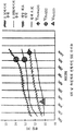
Figure 4 shows charge state curves for a 12 V lead battery under different conditions.
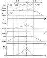
5 is a diagram showing the system voltage during charging and discharging processes, the state of charge of the lead accumulator, and the state of charge of the lithium battery of the hybrid storage system.
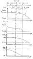
6 shows quantities of FIG. 5 for a discharge process for a high load; FIG.
7 is a flowchart of a charging and discharging process according to the present invention.
8 illustrates a hybrid storage system having a first hybrid battery charging device according to the present invention.
9 illustrates a hybrid storage system having a second hybrid battery charging device according to the present invention.
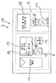
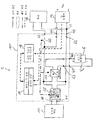
도 1은 본 발명에 따른 하이브리드 축전지 충전 디바이스(10)를 갖는 하이브리드 저장 시스템(5)의 일반적인 배치를 도시한다. 본 발명에 따라, 하이브리드 저장 시스템은 적어도 하나의 축전지를 포함하는 반면에, 하이브리드 충전 디바이스는 반드시 축전지들을 포함하는 것은 아니다.1 shows a general arrangement of a
하이브리드 저장 시스템(5)은 광전지 패널(11), 제 1 에너지 저장 하위시스템(8) 및 제 2 에너지 저장 하위시스템(9)을 포함한다. 제 1 에너지 저장 하위시스템(8)은 납 축전지(12), 단방향 DC/DC 변환기(13) 및 충전 제어 시스템(14)을 포함한다. 충전 제어 시스템(14)은 마이크로제어기(15) 및 센서들(16)을 포함한다. 센서들(16)은 납 축전지의 단자들에서의 전압 센서를 포함한다. DC/DC 변환기(13)는 최대 전력 지점 추적기(MPPT)에 접속된다. 최대 전력 지점 추적기는 임피던스 정합을 광전지 패널(11)에 제공하고 그것은 충전 제어 시스템(14)의 일부 및 또 다른 하드웨어 구성요소들에 의해 실현될 수 있다.The
전형적으로, MPPT는 기준 전압에 및/또는 기준 전류에 대응하는 제어 신호들을 생성하기 위해 광전지 패널(11)에 걸친 전압의 측정치, 광전지 패널(11)로부터의 전류의 측정치, 및 선택적으로, 또 다른 측정치들을 이용한다. MPPT 알고리즘들은 정전압, 섭동(perturb) 및 관측과 증분 컨덕턴스 알고리즘들을 포함한다.Typically, the MPPT is a measure of the voltage across the
특히, 더 높은 출력 전력들(예를 들면, 300 와트보다 많은)을 갖는 원격 에너지 시스템들에 대해, 본 발명에 따른 시스템에서 최대 전력 지점 추적기(MPPT)를 이용하는 것이 이롭다. 그에 의해, 높은 효율성을 성취하는 것이 가능하다. 그러나, 본 발명에 따른 시스템은 MPPT 또는 입력-DC/DC 변환기(13) 없이 오프-그리드 태양광 시스템들을 갖는 것으로서 또한 동작될 수 있다.In particular, for remote energy systems with higher output powers (e.g., greater than 300 watts) it is advantageous to use a maximum power point tracker (MPPT) in the system according to the present invention. Thereby, it is possible to achieve high efficiency. However, the system according to the present invention may also be operated as having off-grid solar systems without an MPPT or input-DC /
제 2 에너지 저장 하위시스템(9)은 리튬 축전지(6), 양방향 DC/DC 변환기(17) 및 전압 모니터링 칩(18)을 포함한다. DC/DC 변환기들(13 및 17)은 예를 들면, 벅 변환기들로서, 부스트 변환기들로서 또는 벅-부스트 변환기들로서 다양한 방식들로 구현될 수 있다.The second energy storage subsystem 9 includes a
도 2는 도 1의 배치의 더 상세한 도면을 보여준다. 도 2의 배치에 따라, 리튬 축전지(6)는 납 축전지(12)에 병렬로 접속되고 양방향 DC/DC 변환기(17)를 통해 부하(19)에 접속된다. 또한, DC/DC 변환기의 출력 라인들은 납 축전지(12)에 병렬로 접속된다. 부하 스위치(20)는 부하(19)에 직렬로 접속된다. 부하 스위치(20)는 깊은 방전을 방지하기 위해 제공되고 그것은 바이폴라 트랜지스터, FET, IGBT, 등과 같은 반도체 스위치로서 구현될 수 있다. 화살표(7)는 전류의 방향을 나타낸다.Figure 2 shows a more detailed view of the arrangement of Figure 1; 2, the
도 2에서의 파선 화살표들은 충전 제어 시스템(14)로의 및 전압 모니터링 칩(18)으로의 센서 신호들의 흐름을 나타내는 반면에, 이점 쇄선 화살표는 충전 제어 시스템(14)과 전압 모니터링 칩 사이의 신호들의 흐름 및 충전 제어 시스템(14)으로부터의 제어 신호들의 흐름을 나타낸다.The dashed arrows in FIG. 2 represent the flow of sensor signals to the
하이브리드 저장 시스템은 광전지 패널(또는 다른 에너지원들)(11)의 대응하는 출력 단자들에 접속되는 양의 입력 단자(40) 및 음의 입력 단자(41), 및 부하(19)의 대응하는 입력 단자들에 접속되는 양의 출력 단자(42) 및 음의 출력 단자(43)를 제공한다. 리튬 하위시스템(9)은 납 축전지(12)의 각각의 단자들에 접속되는 양의 입력 단자(44) 및 음의 입력 단자(45)를 포함한다. 또한, 리튬 하위시스템(9)은 리튬 축전지(6)의 각각의 단자들에 접속되는 양의 출력 단자(46) 및 음의 출력 단자(47)를 포함한다.The hybrid storage system includes a
AC 소비자를 포함하는 부하(19)에 대해, DC/AC 변환기는 출력 단자들(42 및 43)과 부하(19) 사이에 접속될 수 있다. DC/AC 변환기는 예를 들면, 스위칭된 H-브리지 또는 스위칭된 3 위상 인버터에 의해 제공될 수 있다.For a
도 3은 도 2에 따른 하이브리드 저장 시스템(3)의 회로도를 보여준다. 도 3의 예에서, 납 축전지(12)는 약 12V의 전압을 전달할 수 있고 리튬 축전지(6)는 약 24V의 전압을 전달할 수 있다. 광전지 패널(11)은 역 전류 회로 보호 MOSFET(21)(또한 다이오드일 수 있는)를 통해 하이브리드 저장 시스템(5)에 접속된다. 과도 전압 억제(TVS) 및 과전압 억제를 위한 TVS-다이오드(39)는 광전지 패널(11)에 병렬로 접속된다.FIG. 3 shows a circuit diagram of the hybrid storage system 3 according to FIG. In the example of FIG. 3, the lead-
광전지 패널(11)의 출력부들에 및 납 축전지(12)의 축전지 단자들에 접속되는 DC/DC 변환기(13)는 제 1 MOSFET(22), 제 2 MOSFET(24) 및 인덕터(23)를 포함하고, 그들은 성형 결선(star connection)으로 접속된다. 커패시터(25)의 제 1 단자는 납 축전지(12)의 플러스 극 축전지 단자에 접속되고 커패시터(25)의 제 2 단자는 납 축전지(12)의 마이너스 극 축전지 단자에 접속된다.The DC /
또한, 제 2 커패시터(26)는 입력 단자들(40 및 41)에 병렬로 접속되고 입력 필터로서 동작한다. 제 1 MOSFET(22)는 기생 다이오드(27)를 포함하고 제 2 MOSFET는 기생 다이오드(28)를 포함한다.Also, the
동작 동안, 광전지 패널(11)의 또는 DC/DC 변환기(13)의 출력 전력은 충전 제어 시스템(14)에 의해 측정된다. 충전 제어 시스템(14)의 제어 신호는 광전지 패널(11)의 최대 전력 지점에 따라 MOSFET들(22 및 24)의 개방 및 폐쇄를 통해 DC/DC 변환기(13)의 비를 조정한다.During operation, the output power of the
리튬 축전지(6)의 축전지 단자들에 및 납 축전지(12)의 축전지 단자들에 접속되는 DC/DC 변환기(17)는 성형 결선으로 접속되는 제 1 MOSFET(29), 제 2 MOSFET(30) 및 인덕터(31)를 포함한다. 리튬 축전지(6)의 플러스 극 축전지 단자는 커패시터(32)의 제 1 단자에 접속되고 리튬 축전지(6)의 마이너스 극 축전지 단자는 커패시터(32)의 제 2 단자에 접속된다.The DC /
커패시터들(25, 26, 32 및 33)은 한편, 출력 전압을 개선하기 위한 필터들의 역할을 한다.The
제 1 MOSFET(29)는 기생 다이오드(34)를 포함하고 제 2 MOSFET(30)는 기생 다이오드(35)를 포함한다. 보호 MOSFET(21)는 기생 다이오드(36)를 포함하고 부하 스위치(20)는 기생 다이오드(37)를 포함한다. 기생 다이오드들(27, 28, 34, 35, 36 및 37)은 또한 대응하는 MOSFET들(22, 24, 29, 30, 21 및 20)에 대해 프리휠 다이오드(freewheel diode)들로서의 역할을 한다. MOSFET들 대신에, 다른 전계 효과 트랜지스터들이 예를 들면, IGBT들, JFET들 등과 같이, 또한 이용될 수 있다.The
하이브리드 저장 시스템(5)의 양의 출력 단자 가까이에 퓨즈(38)가 제공되어 하이브리드 저장 시스템(5)의 회로를 과부하로부터 보호한다. 접지 포텐셜(38)은 납 축전지(12)의 마이너스 극 단자에, 리튬 축전지(6)의 마이너스 극 단자에 및 DC/DC 변환기(13)의 커패시터(25), 제 2 MOSFET(24) 및 제 2 커패시터(26)의 각각의 단자들에 접속된다.A
본 발명에 따라, 축전지들(6, 12)에서의 별개의 스위치들이 요구되지 않는다. 납 축전지(12) 및 리튬 축전지(6)에는 그러나, 납 축전지(12) 및 리튬 축전지(6)를 접속시키고 분리시키기 위한 스위치들이 각각 구비될 수 있다.According to the invention, no separate switches in the
DC/DC 변환기(13)는 MOSFET들(24 및 22)의 각각의 게이트 전극들에서의 제어 신호들을 통해 제어되고 DC/DC 변환기(17)는 MOSFET들(29 및 30)의 각각의 게이트 전극들에서의 제어 신호들을 통해 제어된다. DC/DC 변환기들(13 및 17)은 각각의 트랜지스터들의 각각의 베이스들 또는 게이트들에서의 펄스 폭 변조된 펄스들을 인가함으로써 충전 펄스 생성기로서 동작될 수 있다.The DC /
충전 모드에서, 충전 펄스들은 축전지들(납 축전지(12) 및 리튬 축전지(6))을 충전하기 위해 이용될 수 있고 복구 모드에서, 그들은 납 축전지(12)의 탈황(desulfurization)을 위해 이용될 수 있다. 충전에 대해서, 용어 "펄스-폭 변조"(PWM)는 반도체 스위치들에서 인가된 신호들을 언급한다. 생성된 전하 또는 전압 펄스들은 일반적으로 직사각형 펄스들의 형태를 취하지 않을 것이다. 이것은 예를 들면, PWM을 통해 모터를 구동시키기 위한 스위칭된 H-브리지의 출력과 상이하다.In the charge mode, the charge pulses can be used to charge the batteries (lead
동작 동안, 리튬 축전지(6)의 전압은 전압 모니터링 칩(18)에 의해 측정되고 납 축전지(12)의 전압은 충전 제어 시스템(14)에 의해 측정된다. 충전 제어 시스템(14)은 MOSFET들(22 및 24)에 대한 제어 신호들을 통해 DC/DC 변환기(13)의 전류를 조정한다. 유사하게, 충전 제어 시스템(14)은 DC/DC 변환기(17)를 통하여, MOSFET들(29 및 30)에 대한 제어 신호들을 통해 전류 또는 전력을 조정한다. DC/DC 변환기들(13 및 17)을 통하여 입력 전압을 증가시킴으로써, 광전지 패널은 심지어 더 약한 일사량의 기간들에서 축전지들(12 및 6)을 충전하기 위해 이용될 수 있다.During operation, the voltage of the
또한, 충전 제어 시스템(14)은 각각의 제어 신호들에 의한 보호 MOSFET(21)의 및 부하 스위치(20)의 개방 및 폐쇄를 제어한다.The
본 발명에 따른 충전 제어 시스템(12)의 제어 신호들의 생성은 이제 다음 도 4 및 도 5에 대하여 더 상세하게 설명된다.The generation of the control signals of the
도 4는 상이한 조건들 하에서 12 V 납 축전지에 대한 충전 상태 곡선들을 보여준다. 가장 높은 곡선은 0.1C의 충전 레이트로 납 축전지를 충전하기 위해 요구되는 외부 전압을 보여준다. 이 충전 레이트는 10 시간 후의 축전지의 용량을 나타낸다. 0.1C의 충전 레이트로, 납 축전지는 약 90%의 충전 상태(SOC)에서 약 13.5V의 충전 종료 전압(V_EOC)에 도달하고, 이는 원 기호에 의해 표시된다. 위로부터의 제 2 곡선은 0.025C의 충전 레이트로 납 축전지를 충전하기 위해 요구되는 외부 전압을 보여준다. 이 경우에, 납 축전지는 약 90%의 충전 상태에서 약 13V의 충전 종료 전압(V_EOC)에 도달하고, 이는 원 기호에 의해 표시된다.Figure 4 shows charge state curves for 12 V lead batteries under different conditions. The highest curve shows the external voltage required to charge the lead acid battery at a charge rate of 0.1C. This charging rate represents the capacity of the battery after 10 hours. At a charge rate of 0.1C, the lead battery reaches a charge end voltage V_EOC of about 13.5V in a state of charge (SOC) of about 90%, which is indicated by a circle symbol. The second curve from the top shows the external voltage required to charge the lead acid battery at a charge rate of 0.025C. In this case, the lead accumulator reaches a charge end voltage V_EOC of about 13 V in a charged state of about 90%, which is indicated by a circle symbol.
아래로부터의 제 2 곡선은 납 축전지의 상이한 충전 상태들에 대한 개방 회로 전압들을 보여준다. 약 12.5 볼트의 최대 개방 회로 전압(V_maxOC)은 다이아몬드 기호에 의해 표시된다. 가장 낮은 곡선은 납 축전지가 약 0.2C의 방전 레이트로 방전되도록 부하가 선택될 때, 납 축전지에 의해 전달되는 전압을 보여준다. 약 35% 축전지 충전의 충전 상태에서, 방전 전압의 끝에 도달된다. 약 11.2 볼트에 있는 방전의 끝에서의 납 축전지의 축전지 단자들 사이의 전압(V_EOD)은 삼각형 기호에 의해 표시된다.The second curve from below shows the open circuit voltages for the different charge states of the lead acid battery. The maximum open circuit voltage (V_maxOC) of about 12.5 volts is indicated by the diamond symbol. The lowest curve shows the voltage delivered by the lead acid battery when the load is selected so that the lead battery discharges at a discharge rate of about 0.2C. At the charge state of about 35% of the battery charge, the end of the discharge voltage is reached. The voltage (V_EOD) between the battery terminals of the lead acid battery at the end of the discharge at about 11.2 volts is indicated by the triangle symbol.
일반적으로, 다음 전압들은 본 발명에 따른 제어 알고리즘들에서 이용된다.In general, the following voltages are used in the control algorithms according to the present invention.
- V_Sys는 Pb 축전지(12)의 전압 및 DC/DC 변환기(17)의 단자들의 제 2 세트에서의 전압에 대응한다. 본 발명에 따라, 어떤 축전지가 충전되거나 방전되는지에 대한 결정은 V_Sys 및 옵션으로서, 전류에 의존한다.- V_Sys corresponds to the voltage in the
- V_EOC는 충전 종료 전압을 나타낸다. 리튬 축전지들에서, 이 전압(V_Li_EOC)은 약 100%의 SOC에 대응할 수 있다. 대조적으로, 납(Pb) 축전지들(V_Pb_EOC)에서의 충전 종료 전압은 85 내지 90%의 SOC에 대응한다. 100%의 SOC에 도달하기 위해, 충전 종료 전압에 도달된 후에 납 축전기가 추가로 충전되어야 한다. 도 4에 도시된 바와 같이, 전압(V_Pb_EOC)는 충전 레이트에 의존할 수 있다. 또한, 그것은 수명 및 동작 온도와 같은 납 축전지의 특성들에 또한 의존한다.- V_EOC represents the charge termination voltage. In lithium batteries, this voltage (V_Li_EOC) may correspond to an SOC of about 100%. In contrast, the charge termination voltage at the lead (Pb) batteries V_Pb_EOC corresponds to an SOC of 85 to 90%. To reach 100% SOC, the lead capacitors must be further charged after the charge termination voltage is reached. As shown in Fig. 4, the voltage V_Pb_EOC may depend on the charge rate. In addition, it also depends on the characteristics of the lead-acid battery, such as lifetime and operating temperature.
- V_EOD는 방전 종료 전압을 나타낸다. 리튬 축전지들에서, 이 전압(V_Li_EOD)은 SOC의 특정 낮은 레벨에 대응하는 반면에, 납 축전지들에서, 축전지에 대한 손상을 회피하기 위해, 이 전압(V_Pb_EOD)은 도 4에 도시된 바와 같은 예를 들면, 30 내지 35%의 SOC에 대응할 것이다. 전압(V_Pb_EOD)은 방전 전류, 축전지의 수명 및 축전지 온도에 또한 의존한다. 그것은 제어 저장 알고리즘에서의 미리 결정된 고정된 값에 대응하지 않는다.- V_EOD represents the discharge end voltage. In lithium batteries, this voltage (V_Li_EOD) corresponds to a certain low level of SOC, whereas in lead accumulators, this voltage (V_Pb_EOD) For example, it will correspond to an SOC of 30 to 35%. The voltage V_Pb_EOD also depends on the discharge current, the lifetime of the battery, and the battery temperature. It does not correspond to a predetermined fixed value in the control storage algorithm.
본 발명에 따른 충전 방법에서, 펄스 폭 변조(PWM) 충전 모드는 납 축전지(12)를 충전하기 위해 이용된다. PWM 충전 모드는 효율적인 충전 모드를 납 축전지들에 제공한다. 납 축전지(12)의 PWM 충전을 위해 필요하지 않은 잉여 에너지는 리튬 하위시스템(9)의 리튬 축전지(6)로 자동으로 전달된다. 그에 의해, 광전지들(11)로부터의 과잉의 전기 에너지는 리튬 축전지(6)를 충전하기 위해 이용된다.In the charging method according to the present invention, the pulse width modulation (PWM) charging mode is used to charge the lead-
본 발명에 따른 방전 방법에서, 리튬 하위시스템은 완전하게 충전된 납 축전지(12)의 전압에 대응하는 임계 전압으로 시스템 전압(V_sys)을 유지하기 위해 제어된다. 시스템 전압(V_sys)은 화살표에 의해 도 2에 표현되고 그것은 리튬 하위시스템(9)의 단자들에 접속되는, 납 축전지(12)에 대한 접속 라인들 사이에서 측정된다.In the discharge method according to the present invention, the lithium subsystem is controlled to maintain the system voltage (V_sys) at a threshold voltage corresponding to the voltage of the fully charged lead acid battery (12). The system voltage V_sys is represented in FIG. 2 by arrows and it is measured between the connection lines to the lead-
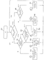
도 5는 본 발명에 따른 방전 처리 동안의 납 축전지에 대한 및 리튬 축전지에 대한 전압 및 충전 상태도들을 보여준다. 도 5 및 도 6에서, 2개의 축전지들의 충전 상태들에 의해 결정되는 시스템 상태들은 문자들(A 내지 E)로 라벨링(labelling)된다. 문자들은 도 7의 흐름도에서의 라벨들에 대응한다. 문자들(A 내지 E)은 충전 및 방전 단계들을 또한 나타낸다. 도 6에 도시된 바와 같이, 부하가, 리튬 축전지(6)가 전달할 수 있는 것보다 많은 전력을 끌어모을 때, 부가적인 방전 단계(D-D')가 존재한다. 이 경우에, 부하에 또한 접속되는 납 축전지는, 시스템 전압이 납 축전지(12)의 충전 종료 전압 아래로 떨어질 때 동시에 방전할 것이다.Figure 5 shows voltage and charge state diagrams for lead accumulators and lithium batteries during the discharge process according to the present invention. In Figures 5 and 6, the system states determined by the charge states of the two batteries are labeled with letters A through E. The letters correspond to the labels in the flow chart of Fig. Characters A through E also denote charging and discharging steps. As shown in FIG. 6, when the load draws more power than the
충전 및 방전 처리 동안, 충전 제어 시스템(14)은 시스템 전압의 시간 의존성에 및/또는 축전지(6, 12)에 공급된 전류에 기초하여 축전지들(6, 12)의 충전 상태들(SOC_Pb 및 SOC_Li)을 추정한다.During charging and discharging processes, the charging
제 1 충전 단계(A)에서, 단지 납 축전지(12)가 충전된다. 도 5의 예에서, 납 축전지(12)에서의 전압은 방전 종료 전압(V_Pb_EOD)에 있고, 리튬 축전지(6)에서의 전압은 방전 종료 전압(V_Li_EOD)에 있다.In the first charging step (A), only the
제 1 충전 상태 동안, 납 축전지(12)의 충전 상태가 증가된다. 납 축전지(12)의 단자들에서의 시스템 전압(V_sys)은 규칙적인 시간 간격들로 측정된다. 시스템 전압(V_sys)이 납 축전지(12)의 충전 종료 전압(V_Pb_EOC)에 도달하자마자, 제 2 충전 단계가 시작된다. 제 2 충전 단계(B)에서, 납 축전지 및 리튬 축전지 둘 모두가 충전된다. 납 축전지(12)의 충전 상태(SOC_Pb)가 대략 100%에 도달하자마자, 제 3 충전 단계(C)가 시작되고, 이 단계에서 리튬 축전지(6)는 전류로 충전되고 납 축전지(12)는 세류 충전으로 동일한 SOC로 유지된다. 이것은 충전 상태도들에서 보여질 수 있고, 상기 충전 상태도들은 리튬 축전지의 충전 상태의 증가 및 납 축전지에 대한 충전의 일정한 상태를 보여준다.During the first charge state, the charge state of the
도 5는 축전지들(6, 12) 둘 모두가 방전 처리의 시작에서 완전하게 충전되는 상황에 대한 본 발명에 따른 방전 처리를 또한 보여준다. 제 1 방전 단계(D)에서, 단지 리튬 축전지(6)가 방전된다. 도 5의 예에서, 리튬 축전지(6)로부터의 방전 전류는 대략 일정하다. 리튬 축전지(6)의 충전 상태가 하한계에 도달하자마자, 단지 납 축전지가 제 2 방전 단계(E)에서 방전된다.Fig. 5 also shows the discharging process according to the present invention for a situation in which both of the
도 5의 예에서, SOC_Li의 하한계에 도달되는 시간은 리튬 축전지에서의 전압이 충전 종료 전압(V_Li_EOC)으로 강하하는 순간에 의해 결정된다. 충전 제어 시스템(14)은, 시스템 전압(V_sys)이 방전 종료 전압(V_Pb_EOD)에 도달할 때 부하 스위치(12)를 개방시킴으로써 부하로부터 납 축전지(12)를 분리시킨다.In the example of FIG. 5, the time to reach the lower limit of SOC_Li is determined by the moment when the voltage at the lithium battery drops to the charge end voltage V_Li_EOC. The
도 6은 제 2 방전 처리를 보여주고, 여기서, 방전 단계(D')에서, 부하는 리튬 축전지가 전달할 수 있는 것보다 많은 전류를 끌어모은다. 이 경우에, 납 축전지(12)의 단자들에서의 시스템 전압(V_sys)은 도 6의 가장 높은 도면에 도시된 바와 같이, 납 축전지의 최대 개방 회로 전압(V_PB_max_OC) 아래로 강하하고, 납 축전지(12)는 리튬 축전지(6)와 함께 방전된다. 방전 단계들(D' 및 E)은 도 5를 참조하여 설명된 방전 단계들과 유사하다.6 shows a second discharging process, wherein in the discharging step (D ') the load draws more current than the lithium battery can deliver. In this case, the system voltage V_sys at the terminals of the lead-
도 7은 충전 제어 시스템(14)의 동작 원리를 나타내는 방전 및 충전 처리의 흐름도를 보여준다.FIG. 7 shows a flow chart of the discharge and charge processing showing the operation principle of the
단계(50)에서, 충전/방전 제어는 예를 들면, 납 축전지(12) 및 리튬 축전지(6)를 플러깅 인(plugging in)함으로써 활성화된다. 이것은 축전지들의 건강상태 및 축전지들의 정확한 접속을 확인하는 것과 같은, 부가적인 단계들을 포함할 수 있다. 결정 단계(51)에서, 충분한 전력이 축전지들을 충전하기 위해 이용가능한지의 여부가 결정된다. 결정 단계(52)에서, 납 축전지(12)가 예를 들면, 시스템 전압(V_sys)을 측정함으로써 완전하게 충전되는지가 결정된다. 납 축전지(12)가 완전하게 충전된 것으로서 결정되면, 리튬 축전지(6)가 충전되고 납 축전지(12)에는 단계(53)에서 세류 충전이 제공된다. 납 축전지(12)가 아직 완전하게 충전되지 않았다고 단계(52)에서 결정되면, 결정 단계(54)에서, 납 축전지(12)가 충전 종료 전압에 도달했는지가 결정된다.In
납 축전지(12)가 아직 충전 종료 전압에 도달하지 않았다면, 그것은 단계(58)에서 충전된다. 한편, 납 축전지가 충전 종료 전압에 도달했다고 결정되면, 리튬 축전지(6)가 동시에 충전되는 동안 납 축전지(12)는 일정한 전압으로 충전된다. 결정 단계(51)에서, 생성이 소비를 초과하지 않고 소비가 0보다 크다고 결정되면, 결정 단계(55)에서, 리튬 축전지(6)가 비어있는지가 결정되고, 여기서 "비어있는"은 낮은 SOC에 대응한다. 리튬 축전지(6)가 비어 있다고 결정되면, 납 축전지(12)는 단계(56)에서 방전되는 반면에, 납 축전지(12)의 충전 상태(SOC_Pb)는 예를 들면, 30 내지 40%의 하한계를 초과한다. 한편, 리튬 축전지(6)가 비어 있지 않다고 단계(55)에서 결정되면, 리튬 축전지(6)는 단계(57)에서 방전된다. 단계(56)의 실행 동안, 부하가, 리튬 축전지(6)가 공급할 수 있는 것보다 많은 전류를 끌어모으면, 납 축전지(12)의 단자들에서의 전압은 충전 종료 전압(V_EOC_Pb) 아래로 강하하고 납 축전지(12)는 또한 방전될 것이다.If the lead-
도 8 및 도 9는 도 1 내지 도 3의 실시예와 유사한 하이브리드 저장 시스템(5)의 또 다른 실시예들을 보여준다. 도 8 및 도 9의 실시예들에 따라, 축전지들(6 및 12)은 하이브리드 저장 시스템(5)의 부분을 형성하지 않지만 하이브리드 저장 시스템(5)에 플러깅된다.8 and 9 show still another embodiment of a
하나의 예에 따라, 축전지들(6, 12)에는 전압 센서들 및 전압 센서들을 하이브리드 저장 시스템(10)에 접속시키기 위한 접속부들이 제공된다. 또 다른 예에 따라, 하이브리드 저장 시스템에는 납 축전지 전압 센서(62) 및 리튬 축전지 전압 센서(63)가 제공된다. 또한, 입력 전압 센서(64) 및 공급 전류 센서(65)가 제공될 수 있다. 오픈 서클(open circle)들에 의해 기호화되는 센서들은 다양한 방식들로 실현될 수 있다. 예를 들면, 센서들은 2개의 대응하는 전기 라인들 또는 단지 하나의 전기 라인에 접속될 수 있다. 전류 센서는 자기장 센서로서 또한 제공될 수 있다.According to one example, the
도 10의 실시예는 도 9의 실시예와 유사하지만, 앞선 실시예와 대조적으로 하이브리드 저장 시스템(10)은 리튬 축전지(6)의 단말들에서의 전압의 조정을 위해 제공되는 단지 하나의 DC/DC 변환기(17)를 포함한다. 제 2 DC/DC 변환기(13) 대신에, 입력 전류 조정 수단(13') 예를 들면, 제어가능한 온/오프 스위치, 제어가능한 펄스 폭 변조(PWM), 과전압 보호 등이 제공된다. 전류 조정 수단은 도 10에 도시된 바와 같이, 제어 라인에 의해 충전 제어 시스템(14)에 접속될 수 있다.The embodiment of Figure 10 is similar to the embodiment of Figure 9, but in contrast to the previous embodiment, the
상기 언급된 설명에서, 본 발명의 실시예들을 설명하기 위한 상세들이 제공되었다. 그러나, 실시예들이 이러한 상세들 없이 실행될 수 있음이 당업자에게 명백할 것이다. 예를 들면, 하이브리드 저장 시스템의 구성요소들을 실현하기 위한 다양한 회로 장치들이 존재한다. 이들 회로 장치들은 상세한 실시예에서 도시된 기능들과 유사한 기능들을 갖는 부가적인 구성요소들 또는 다른 구성요소들을 가질 수 있다. 예를 들면, 트랜지스터들은 실시예들에서의 n-형 유니폴라 트랜지스터들로서 도시된다. 그러나, 당업자들은 장치가 p-형 트랜지스터들로 또한 실현될 수 있음을 이해할 것이다. 다른 수정들은 예를 들면, 축전지들의 극성을 반전시키거나, 전압 센서들을 상이한 위치들에 위치시키는 것 등으로부터 발생할 수 있다.In the above description, details have been provided for illustrating embodiments of the present invention. However, it will be apparent to those skilled in the art that the embodiments may be practiced without these details. For example, there are various circuit devices for realizing the components of the hybrid storage system. These circuit devices may have additional components or other components having similar functions to those shown in the detailed embodiments. For example, the transistors are shown as n-type unipolar transistors in embodiments. However, those skilled in the art will appreciate that the device can also be realized as p-type transistors. Other modifications may arise, for example, from reversing the polarity of the batteries, placing the voltage sensors at different locations, and the like.
5: 하이브리드 저장 시스템
6: 리튬 축전지
8: 제 1 에너지 저장 하위시스템
9: 제 2 에너지 저장 하위시스템
10: 하이브리드 축전지 충전 디바이스
11: 광전지 패널
12: 납 축전지
13: 단방향 DC/DC 변환기
14: 충전 제어 시스템
15: 마이크로제어기
16: 센서들
17: 양방향 DC/DC 변환기
19: 부하
20, 21, 22, 24, 29, 30: MOSFET들
23: 인덕터
25, 26, 32, 33: 커패시터들
27, 28, 34, 35, 36, 37: 기생 다이오드들
39: TVS-다이오드
40, 42, 44: 양의 입력 단자
41, 43, 45: 음의 입력 단자5: Hybrid storage system 6: Lithium accumulator
8: First energy storage subsystem
9: Second energy storage subsystem
10: Hybrid battery charging device 11: Photovoltaic panel
12: lead acid battery 13: unidirectional DC / DC converter
14: charge control system 15: microcontroller
16: sensors 17: bi-directional DC / DC converter
19: Load
20, 21, 22, 24, 29, 30: MOSFETs 23: inductor
25, 26, 32, 33: capacitors
27, 28, 34, 35, 36, 37: parasitic diodes 39: TVS-diodes
40, 42, 44: Positive input terminal
41, 43, 45: Negative input terminal
Claims (24)
- 광전지 패널을 접속시키기 위한 입력 단자들(40, 41),
- 납 축전지(12)를 접속시키기 위한 제 1 축전지 접속부들(44, 45),
- 높은 사이클 화학 축전지(6)를 접속시키기 위한 제 2 축전지 접속부들(46, 47),
- 양방향 DC/DC 변환기(17)로서, 상기 양방향 DC/DC 변환기(17)의 단자들의 제 1 세트는 상기 제 2 축전지 접속부들(46, 47)과 접속되고, 상기 양방향 DC/DC 변환기(17)의 단자들의 제 2 세트는 상기 제 1 축전지 접속부들(44, 45)과 접속되는, 상기 양방향 DC/DC 변환기(17),
- 각각의 제어 라인들을 통해 상기 DC/DC 변환기(17)에 접속되는 충전 및 방전 제어 시스템(14), 및
- 부하(19)를 접속시키기 위한 출력 단자들(42, 43)로서, 상기 출력 단자들로의 입력은 상기 제 1 축전지 접속부들(44, 45)로부터 얻어지는, 상기 출력 단자들(42, 43)을 포함하는, 하이브리드 축전지 충전 디바이스.In the hybrid battery charging device (10)
- input terminals (40, 41) for connecting photovoltaic panels,
- first battery connection portions (44, 45) for connecting the lead-acid battery (12)
- secondary battery connections (46, 47) for connecting the high cycle chemical storage battery (6)
- a bidirectional DC / DC converter (17), wherein a first set of terminals of the bidirectional DC / DC converter (17) is connected to the second battery connections (46, 47) and the bidirectional DC / DC converter Directional DC / DC converter (17), a second set of terminals of the bidirectional DC / DC converter
- a charge and discharge control system (14) connected to the DC / DC converter (17) via respective control lines, and
- an output terminal (42, 43) for connecting the load (19), the input to said output terminals being connected to said output terminals (42, 43) obtained from said first battery- And a charging device for charging the battery.
- 상기 충전 및 방전 제어 시스템(14)에 접속되는 제어 디바이스(13)로서, 상기 제어 디바이스(13)의 입력 단말들은 상기 입력 단말들(40, 41)에 접속되고, 상기 제어 디바이스(13)의 출력 단말들은 상기 DC/DC 변환기(17)의 입력 단말들에 접속되는, 상기 제어 디바이스(13)를 추가로 포함하는, 하이브리드 축전지 충전 디바이스.In the hybrid battery charging device (10)
A control device (13) connected to the charging and discharging control system (14), the input terminals of the control device (13) being connected to the input terminals (40, 41) Wherein the output terminals are connected to the input terminals of the DC / DC converter (17).
상기 제어 디바이스(13)는 펄스 폭 변조를 포함하는, 하이브리드 축전지 충전 디바이스.3. The method of claim 2,
Wherein the control device (13) comprises pulse width modulation.
상기 제어 디바이스(13)는 최대 전력 지점 추적기를 포함하는, 하이브리드 축전지 충전 디바이스.The method according to claim 2 or 3,
Wherein the control device (13) comprises a maximum power point tracker.
상기 제어 디바이스(13)는 제어가능한 스위치(13')를 포함하는, 하이브리드 축전지 충전 디바이스.The method according to claim 2 or 3,
The control device (13) comprises a controllable switch (13 ').
상기 제어 디바이스(13)는 DC/DC 변환기(13')를 포함하는, 하이브리드 축전지 충전 디바이스.The method according to claim 2 or 3,
The control device (13) includes a DC / DC converter (13 ').
상기 양방향 DC/DC 변환기(17)는 벅-부스트(buck-boost) 변환기, 벅 변환기, 부스트 변환기 또는 또 다른 변환기 토폴로지를 포함하는, 하이브리드 축전지 충전 디바이스.7. The method according to any one of claims 1 to 6,
Wherein the bidirectional DC / DC converter (17) comprises a buck-boost converter, a buck converter, a boost converter or another converter topology.
상기 양방향 DC/DC 변환기(17)는 적어도 2개의 반도체 스위치들(29, 30)을 포함하고, 상기 트랜지스터들(29, 30)의 각각의 입력 접속부들은 각각의 제어 라인들을 통해 상기 충전 제어 시스템(14)에 접속되는, 하이브리드 축전지 충전 디바이스.8. The method according to any one of claims 1 to 7,
The bidirectional DC / DC converter (17) includes at least two semiconductor switches (29, 30), and the respective input connections of the transistors (29, 30) 14). ≪ / RTI >
- 제 1 전압 센서를 접속시키기 위한 제 1 전압 측정 접속부들로서, 상기 제 1 전압 센서는 상기 납 축전지(12)의 단자들에 접속되고 상기 제 1 전압 측정 접속부들은 상기 충전 및 방전 제어 시스템(14)에 접속되는, 상기 제 1 전압 측정 접속부들, 및
- 제 2 전압 센서를 접속시키기 위한 제 2 전압 측정 접속부들로서, 상기 제 2 전압 센서는 상기 높은 사이클 화학 축전지의 단자들에 접속되고 상기 제 2 전압 측정 접속부들은 상기 충전 및 방전 제어 시스템(14)에 접속되는, 상기 제 2 전압 측정 접속부들을 포함하는, 하이브리드 축전지 충전 디바이스.9. The method according to any one of claims 1 to 8,
- first voltage measurement connections for connecting a first voltage sensor, said first voltage sensor being connected to terminals of said lead acid battery (12) and said first voltage measurement connections being connected to said charge and discharge control system (14) , Said first voltage measurement connections being connected to said first voltage measurement connections
Second voltage measurement connections for connecting a second voltage sensor, said second voltage sensor being connected to terminals of said high cycle chemical battery and said second voltage measurement connections being connected to said charging and discharging control system (14) Said second voltage measurement connections being connected to said second voltage measurement contacts.
상기 높은 사이클 화학 축전지를 위한 별개의 축전지 관리 시스템(18)으로서, 상기 충전 및 방전 제어 시스템(14)에 접속되는, 상기 별개의 축전지 관리 시스템(18)을 포함하는, 하이브리드 축전지 충전 디바이스.3. The method according to claim 1 or 2,
A separate battery management system (18) for the high cycle chemical battery, the separate battery management system (18) being connected to the charge and discharge control system (14).
제 2 축전지 접속부들(46, 47)에 접속되는 높은 사이클 화학 축전지(6)를 추가로 포함하는, 하이브리드 저장 시스템.11. A hybrid storage system (5) having a hybrid charging device (10) according to any one of claims 1 to 10,
Further comprising a high cycle chemical battery (6) connected to the secondary battery connection portions (46, 47).
상기 높은 사이클 화학 축전지(6)는 리튬 축전지(6)를 포함하는, 하이브리드 저장 시스템.12. The method of claim 11,
Wherein the high cycle chemical battery (6) comprises a lithium battery (6).
상기 높은 사이클 화학 축전지(6)에 병렬로 접속되는 커패시터를 추가로 포함하는, 하이브리드 저장 시스템.12. The method of claim 11,
Further comprising a capacitor connected in parallel to said high cycle chemical battery (6).
제 1 축전지 접속부들(44, 45)에 접속되는 납 축전지(12)를 추가로 포함하는, 하이브리드 저장 시스템.14. The method according to any one of claims 11 to 13,
Further comprising a lead accumulator (12) connected to the first battery connection (44, 45).
- 상기 제 1 축전지(12)의 단자와 충전 및 방전 제어 시스템(14)에 접속되는 제 1 전압 센서, 및
- 상기 제 2 축전지(6)의 단자와 상기 충전 및 방전 제어 시스템(14)에 접속되는 제 2 전압 센서를 추가로 포함하는, 하이브리드 저장 시스템.15. The method according to any one of claims 11 to 14,
- a first voltage sensor connected to the terminals of the first battery (12) and the charging and discharging control system (14), and
- a second voltage sensor connected to the terminal of said second battery (6) and said charging and discharging control system (14).
- 상기 납 축전지(12)가 제 1 미리 결정된 충전 상태에 도달할 때까지 제 1 축전지 충전 단계에서 상기 납 축전지(12)를 충전하는 단계,
- 상기 납 축전지(12)가 제 2 미리 결정된 충전 상태에 도달할 때까지 토핑(topping)/부스트/등화 단계에서 상기 납 축전지(12) 및 상기 높은 사이클 화학 축전지(6)를 충전하는 단계, 및
- 제 3 축전지 충전 단계에서 상기 높은 사이클 화학 축전지(6)를 충전하는 단계로서, 상기 제 3 축전지 충전 단계 동안, 필수적으로 일정한 시스템 전압은 상기 납 축전지(12)의 시스템 단자들에 인가되고 상기 시스템 전압은 상기 높은 사이클 화학 축전지(6)의 단자들에서의 충전 전압으로 변환 특히, 업-변환되는, 상기 높은 사이클 화학 축전지를 충전하는 단계를 포함하는, 납 축전지 및 높은 사이클 화학 축전지를 충전하기 위한 방법.A method for charging a lead storage battery (12) and a high cycle chemical storage battery (6) of a hybrid storage system (5) by an electric power source (11)
- charging the lead storage battery (12) in a first battery charging step until the lead storage battery (12) reaches a first predetermined charging state,
Charging the lead accumulator 12 and the high cycle chemical battery 6 in a topping / boost / equalization step until the lead accumulator 12 reaches a second predetermined charge state, and
Charging the high cycle chemical battery (6) in a third battery charging step, wherein during the third battery charging step essentially constant system voltage is applied to system terminals of the lead storage battery (12) and the system The method of any one of the preceding claims, wherein the voltage is converted into a charging voltage at the terminals of the high cycle chemical battery (6), in particular charging the high cycle chemical battery Way.
상기 등화 단계는 미리 결정된 하위 전압과 미리 결정된 상위 전압 사이를 발진하는 상기 납 축전지에서의 전압을 인가하는 단계를 추가로 포함하는, 납 축전지 및 높은 사이클 화학 축전지를 충전하기 위한 방법.17. The method of claim 16,
Wherein the equalizing further comprises applying a voltage at the lead accumulator oscillating between a predetermined lower voltage and a predetermined upper voltage. ≪ Desc / Clms Page number 13 >
상기 등화 단계 동안 상기 납 축전지(12)의 단자들에서의 평균 전압을 상기 납 축전지(12)의 충전 종료 전압으로 유지하는 단계를 추가로 포함하는, 납 축전지 및 높은 사이클 화학 축전지를 충전하기 위한 방법.18. The method according to claim 16 or 17,
Further comprising the step of maintaining an average voltage at the terminals of the lead accumulator (12) at the charge end voltage of the lead accumulator (12) during the equalization step .
상기 등화 단계 동안, 상기 납 축전지의 단자들에서의 시스템 전압은, 상기 납 축전지로의 충전 전압이 감소되고 잔여 충전 전력이 상기 높은 사이클 화학 축전지(6)로 전달되도록 일정하게 제어되는, 납 축전지 및 높은 사이클 화학 축전지를 충전하기 위한 방법.19. The method according to any one of claims 16 to 18,
During the equalization step, the system voltage at the terminals of the lead accumulator is constantly controlled such that the charge voltage to the lead accumulator is reduced and the remaining charge power is delivered to the high cycle chemical battery (6) A method for charging a high cycle chemical storage battery.
상기 제 3 축전지 충전 단계에서 상기 높은 사이클 화학 축전지(6)의 충전 동안 상기 시스템 단자들에 인가되는 상기 필수적으로 일정한 시스템 전압은 상기 납 축전지(12)의 최대 개방 회로 전압(V_Pb_maxOC)과 같은, 납 축전지 및 높은 사이클 화학 축전지를 충전하기 위한 방법.20. The method according to any one of claims 16 to 19,
The essentially constant system voltage applied to the system terminals during the charging of the high cycle chemical battery 6 in the third battery charging step is equal to the maximum open circuit voltage V_Pb_maxOC of the lead accumulator 12, A method for charging a battery and a high cycle chemical storage battery.
상기 등화 단계를 시작하기 위한 결정 및 상기 제 3 축전지 충전 단계를 시작하기 위한 결정은 상기 납 축전지의 단자들에서의 시스템 전압에 의존하여 이루어지는, 납 축전지 및 높은 사이클 화학 축전지를 충전하기 위한 방법.21. The method according to any one of claims 16 to 20,
Wherein the determination to start the equalizing step and the determination to start the third battery charging step are made dependent on the system voltage at the terminals of the lead accumulator.
- 상기 높은 사이클 화학 축전지(6)의 출력 전압이 상기 높은 사이클 화학 축전지(6)의 방전 종료 전압에 도달할 때까지, 상기 납 축전지(12)의 시스템 단자들을 통해 상기 높은 사이클 화학 축전지(6)를 방전시킴으로써 및 상기 납 축전지(12)의 최대 개방 회로 전압에 필수적으로 동일한, 상기 시스템 단자들에서의 전압을 유지함으로써 전력을 부하(19)에 공급하는 단계, 및
- 상기 납 축전지(12)의 전압이 상기 납 축전지(12)의 방전 종료 전압에 도달할 때까지 상기 납 축전지(12)를 방전시키는 단계를 포함하는, 납 축전지 및 높은 사이클 화학 축전지를 방전시키기 위한 방법.A method for discharging a lead-acid battery (12) and a high-cycle chemical battery (6) of a hybrid storage system (5)
(6) through the system terminals of the lead accumulator battery (12) until the output voltage of the high cycle chemical battery (6) reaches the discharge end voltage of the high cycle chemical battery (6) Supplying power to the load (19) by maintaining the voltage at the system terminals essentially equal to the maximum open circuit voltage of the lead-acid battery (12), and
Discharging the lead-acid battery (12) until the voltage of the lead-acid battery (12) reaches the discharge end voltage of the lead-acid battery (12) Way.
상기 높은 사이클 화학 축전지(6)를 방전시키는 단계 및 상기 납 축전지(12)를 방전시키는 단계는 병렬로 실행되는, 납 축전지 및 높은 사이클 화학 축전지를 방전시키기 위한 방법.23. The method of claim 22,
Wherein discharging the high cycle chemical battery (6) and discharging the lead accumulator (12) are performed in parallel.
상기 충전 및 방전 제어 시스템(14)은 제 16 항 내지 제 23 항 중 어느 한 항에 따른 방법의 단계들을 실행하기 위한 수단을 포함하는, 하이브리드 축전지 충전 디바이스.9. The method according to any one of claims 1 to 8,
Wherein the charge and discharge control system (14) comprises means for performing the steps of the method according to any one of claims 16 to 23.
Applications Claiming Priority (1)
| Application Number | Priority Date | Filing Date | Title |
|---|---|---|---|
| PCT/IB2012/054534 WO2014033505A1 (en) | 2012-09-03 | 2012-09-03 | Topology and control strategy for hybrid storage systems |
Publications (1)
| Publication Number | Publication Date |
|---|---|
| KR20150048875A true KR20150048875A (en) | 2015-05-07 |
Family
ID=50182591
Family Applications (1)
| Application Number | Title | Priority Date | Filing Date |
|---|---|---|---|
| KR1020157008483A KR20150048875A (en) | 2012-09-03 | 2012-09-03 | Topology and control strategy for hybrid storage systems |
Country Status (9)
| Country | Link |
|---|---|
| US (1) | US20150270731A1 (en) |
| EP (1) | EP2893609A4 (en) |
| KR (1) | KR20150048875A (en) |
| CN (1) | CN105052004A (en) |
| AU (1) | AU2012388678B2 (en) |
| IN (1) | IN2015DN01550A (en) |
| SG (1) | SG11201501326UA (en) |
| WO (1) | WO2014033505A1 (en) |
| ZA (1) | ZA201502236B (en) |
Cited By (1)
| Publication number | Priority date | Publication date | Assignee | Title |
|---|---|---|---|---|
| KR20200100778A (en) * | 2018-01-09 | 2020-08-26 | 첸시앙 차오 | Solar energy smart facility |
Families Citing this family (25)
| Publication number | Priority date | Publication date | Assignee | Title |
|---|---|---|---|---|
| DE112012001144T5 (en) * | 2011-03-07 | 2013-11-28 | A123 Systems, Inc. | Method for opportunistically equalizing charge between battery cells |
| US11901810B2 (en) | 2011-05-08 | 2024-02-13 | Koolbridge Solar, Inc. | Adaptive electrical power distribution panel |
| US9525305B2 (en) * | 2012-08-22 | 2016-12-20 | Sharp Kabushiki Kaisha | Electric system and vehicle |
| CN104184200A (en) * | 2013-05-24 | 2014-12-03 | 台达电子工业股份有限公司 | Power supply adapter, power supply adapter control method and notebook |
| EP3031119A2 (en) | 2013-09-09 | 2016-06-15 | Apple Inc. | Universal power adapter |
| US9975434B2 (en) * | 2013-09-24 | 2018-05-22 | Ford Global Technologies, Llc | System and method for monitoring contactor health |
| US11916205B2 (en) * | 2013-10-02 | 2024-02-27 | Lt 350, Llc | Energy storage canopy |
| JP5915619B2 (en) * | 2013-10-22 | 2016-05-11 | トヨタ自動車株式会社 | Photovoltaic power generation device and control method of solar power generation device |
| JP6448225B2 (en) * | 2014-06-17 | 2019-01-09 | 三星エスディアイ株式会社Samsung SDI Co., Ltd. | Power assist unit and power assist system |
| US10128656B2 (en) | 2014-06-17 | 2018-11-13 | Samsung Sdi Co., Ltd. | Power assist unit and power assist system |
| US9847751B2 (en) * | 2014-07-30 | 2017-12-19 | International Business Machines Corporation | Techniques for optimizing photo-voltaic power via inductive coupling |
| DE102017100872A1 (en) * | 2016-01-21 | 2017-07-27 | Thermo King Corporation | Automobile-type transient protection methods and systems for a solar charging source |
| EP3217465A1 (en) | 2016-03-08 | 2017-09-13 | BOS Balance of Storage Systems AG | System for storing electrical energy |
| DE202016101273U1 (en) | 2016-03-08 | 2016-04-13 | Bos Balance Of Storage Systems Ag | System for storing electrical energy |
| US11196272B2 (en) * | 2016-06-29 | 2021-12-07 | Koolbridge Solar, Inc. | Rapid de-energization of DC conductors with a power source at both ends |
| CA3036927A1 (en) * | 2016-09-15 | 2018-03-22 | Nantenergy, Inc. | Hybrid battery system |
| JP6583294B2 (en) * | 2017-01-17 | 2019-10-02 | トヨタ自動車株式会社 | Electric vehicle |
| US20180233929A1 (en) * | 2017-02-13 | 2018-08-16 | Spiers New Technologies, Inc. | Battery to battery charger using asymmetric batteries |
| CN107317379A (en) * | 2017-08-22 | 2017-11-03 | 上海点贸信息技术有限公司 | A kind of battery charging module |
| WO2019058821A1 (en) * | 2017-09-22 | 2019-03-28 | 株式会社村田製作所 | Power storage apparatus |
| CN110350855B (en) | 2018-04-02 | 2022-03-04 | 耐克斯特拉克尔有限公司 | Multi-power supply system for photovoltaic cell control |
| CN208386480U (en) * | 2018-04-02 | 2019-01-15 | 耐克斯特拉克尔有限公司 | Multi-power system for photovoltaic cell control |
| JP7020293B2 (en) * | 2018-05-25 | 2022-02-16 | トヨタ自動車株式会社 | Battery discharge controller |
| CN109672252A (en) * | 2019-02-15 | 2019-04-23 | 深圳硕日新能源科技有限公司 | A kind of double-battery charge electric control system |
| CN113748581A (en) | 2019-02-22 | 2021-12-03 | 波拉里尔姆能源解决方案公司 | Battery module protected by reverse polarity |
Family Cites Families (24)
| Publication number | Priority date | Publication date | Assignee | Title |
|---|---|---|---|---|
| US5447522A (en) * | 1993-10-20 | 1995-09-05 | Intermedics, Inc. | Capacitor charging circuit for implantable defibrillator |
| JP3323832B2 (en) * | 1999-06-08 | 2002-09-09 | インターナショナル・ビジネス・マシーンズ・コーポレーション | Method of controlling charge and discharge of multiple batteries |
| US6353304B1 (en) * | 2001-01-19 | 2002-03-05 | Sandia Corporation | Optimal management of batteries in electric systems |
| CA2380945A1 (en) * | 2002-04-08 | 2003-10-08 | Powergenix Systems, Inc. | Hybrid battery configuration |
| JP2007526730A (en) * | 2003-06-17 | 2007-09-13 | エコソル ソーラー テクノロジーズ,リミテッド | Two-stage energy storage device |
| JP3887635B2 (en) * | 2003-10-30 | 2007-02-28 | シャープ株式会社 | Independent power system |
| JP2006050779A (en) * | 2004-08-04 | 2006-02-16 | Toyota Motor Corp | Motor driving device |
| JP2007228753A (en) * | 2006-02-24 | 2007-09-06 | Toyota Motor Corp | Electric vehicle |
| TW200827974A (en) * | 2006-12-18 | 2008-07-01 | Ming-Hsin Sun | Power tracking system of solar energy system and the method thereof |
| ES2367589T3 (en) * | 2007-11-29 | 2011-11-04 | National University Of Ireland Galway | BATTERY CHARGER AND PROCEDURE. |
| US20090284217A1 (en) * | 2008-05-14 | 2009-11-19 | Nien Made Enterprise Co., Ltd. | Solar power charging device with self-protection function |
| US20090317696A1 (en) * | 2008-06-19 | 2009-12-24 | Chih-Peng Chang | Compound battery device having lithium battery and lead-acid battery |
| US8115446B2 (en) * | 2008-11-12 | 2012-02-14 | Ford Global Technologies, Llc | Automotive vehicle power system |
| CN102369619A (en) * | 2009-01-15 | 2012-03-07 | 菲斯科汽车公司 | Solar power in a vehicle |
| CN102449873A (en) * | 2009-04-01 | 2012-05-09 | 伊格皮切尔科技有限责任公司 | Hybrid energy storage system, renewable energy system including the storage system, and method of using same |
| US9199543B2 (en) * | 2009-07-31 | 2015-12-01 | Thermo King Corporation | Bi-directional battery voltage converter |
| KR101084214B1 (en) * | 2009-12-03 | 2011-11-18 | 삼성에스디아이 주식회사 | Grid-connected energy storage system and method for controlling grid-connected energy storage system |
| JP5051264B2 (en) * | 2010-04-08 | 2012-10-17 | 株式会社デンソー | Battery voltage monitoring device |
| KR101113508B1 (en) * | 2010-05-06 | 2012-02-29 | 성균관대학교산학협력단 | Apparatus and method for charging and discharging photovoltaic pcs integrated battery |
| JP2012056462A (en) * | 2010-09-09 | 2012-03-22 | Furukawa Electric Co Ltd:The | Apparatus and method for controlling, and system for vehicular electrical power supply |
| CA2816843C (en) * | 2010-11-02 | 2019-12-10 | Navitas Solutions, Inc. | Wireless battery area network for a smart battery management system |
| US8970161B1 (en) * | 2011-06-29 | 2015-03-03 | Carlos Cuadros | Modulation control scheme for power converters in photovoltaic system charge controllers |
| CN102593907A (en) * | 2012-02-29 | 2012-07-18 | 华为技术有限公司 | Power supply method and device as well as base station |
| US9035622B2 (en) * | 2012-06-21 | 2015-05-19 | Go-Tech Energy Co. Ltd. | Charging device with battery management system for rechargeable battery |
-
2012
- 2012-09-03 WO PCT/IB2012/054534 patent/WO2014033505A1/en active Application Filing
- 2012-09-03 SG SG11201501326UA patent/SG11201501326UA/en unknown
- 2012-09-03 KR KR1020157008483A patent/KR20150048875A/en not_active Application Discontinuation
- 2012-09-03 EP EP12883672.3A patent/EP2893609A4/en not_active Withdrawn
- 2012-09-03 IN IN1550DEN2015 patent/IN2015DN01550A/en unknown
- 2012-09-03 US US14/424,167 patent/US20150270731A1/en not_active Abandoned
- 2012-09-03 AU AU2012388678A patent/AU2012388678B2/en not_active Ceased
- 2012-09-03 CN CN201280076249.XA patent/CN105052004A/en active Pending
-
2015
- 2015-03-31 ZA ZA2015/02236A patent/ZA201502236B/en unknown
Cited By (1)
| Publication number | Priority date | Publication date | Assignee | Title |
|---|---|---|---|---|
| KR20200100778A (en) * | 2018-01-09 | 2020-08-26 | 첸시앙 차오 | Solar energy smart facility |
Also Published As
| Publication number | Publication date |
|---|---|
| CN105052004A (en) | 2015-11-11 |
| SG11201501326UA (en) | 2015-03-30 |
| US20150270731A1 (en) | 2015-09-24 |
| EP2893609A1 (en) | 2015-07-15 |
| ZA201502236B (en) | 2016-01-27 |
| AU2012388678B2 (en) | 2016-03-17 |
| IN2015DN01550A (en) | 2015-07-03 |
| AU2012388678A1 (en) | 2015-03-19 |
| WO2014033505A1 (en) | 2014-03-06 |
| EP2893609A4 (en) | 2016-04-13 |
Similar Documents
| Publication | Publication Date | Title |
|---|---|---|
| KR20150048875A (en) | Topology and control strategy for hybrid storage systems | |
| US20170155274A1 (en) | Topology and control strategy for hybrid storage systems | |
| US20170070081A1 (en) | Hybrid storage system | |
| KR101116483B1 (en) | Energy Storage System | |
| US7566828B2 (en) | Power source device and charge controlling method to be used in same | |
| US20170070085A1 (en) | Hybrid storage system | |
| US20120025752A1 (en) | Battery charger | |
| US20090079385A1 (en) | Solar powered battery charger using switch capacitor voltage converters | |
| JP5836283B2 (en) | Charge equalization system for batteries | |
| TW201532365A (en) | Topology and control strategy for hybrid storage systems | |
| CN111357148A (en) | Power storage module and power supply system | |
| CN102918745A (en) | Solar cell system | |
| WO2015017896A1 (en) | Battery balancing system and method | |
| JP2013102571A (en) | Power supply device, power control system, and starting method of electrical apparatus | |
| JP2013099207A (en) | Control apparatus and control method | |
| JP2016067131A (en) | Charger system | |
| AU2018402306B2 (en) | Solar-powered intelligent apparatus | |
| US20220398675A1 (en) | Smart Energy Management System (SEMS) | |
| JP2013102578A (en) | Control apparatus and control method | |
| JP2018129980A (en) | Photovoltaic power generation system | |
| EP2706607B1 (en) | Desulphation of lead-acid batteries | |
| CN213151910U (en) | Power supply conversion control circuit and device | |
| CN201243220Y (en) | Simple charging circuit for mobile phone battery through hand generator | |
| CN117595449A (en) | Charging and discharging control device, charging control method and discharging control method |
Legal Events
| Date | Code | Title | Description |
|---|---|---|---|
| WITN | Application deemed withdrawn, e.g. because no request for examination was filed or no examination fee was paid |