JP4575876B2 - Inverter device and inverter system - Google Patents
Inverter device and inverter system Download PDFInfo
- Publication number
- JP4575876B2 JP4575876B2 JP2005338694A JP2005338694A JP4575876B2 JP 4575876 B2 JP4575876 B2 JP 4575876B2 JP 2005338694 A JP2005338694 A JP 2005338694A JP 2005338694 A JP2005338694 A JP 2005338694A JP 4575876 B2 JP4575876 B2 JP 4575876B2
- Authority
- JP
- Japan
- Prior art keywords
- output
- polarity
- inverter
- inverter device
- current
- Prior art date
- Legal status (The legal status is an assumption and is not a legal conclusion. Google has not performed a legal analysis and makes no representation as to the accuracy of the status listed.)
- Active
Links
Images


Description
本発明は、並列冗長運転に使用されるインバータ装置及び、並列冗長運転を行うインバータシステムに関する。 The present invention relates to an inverter device used for parallel redundant operation and an inverter system that performs parallel redundant operation.
図3に示すように、1つの直流電源(DC電源)31に接続された複数台のインバータ装置(#1〜#n)1〜nを並列冗長運転し、1つの負荷32に交流電力を供給するインバータシステムがある。直流電源31は、例えば、商用交流電源をダイオードで整流しコンデンサなどで平滑することにより得られるコンバータであり、インバータ装置1〜nは、直流を交流に変換する電圧型のインバータ装置である。複数台のインバータ装置(#1〜#n)1〜nの各々の出力側は、母線3にリレー4−1〜4−nを介して負荷32に接続されている。
As shown in FIG. 3, a plurality of inverter devices (# 1 to #n) 1 to n connected to a single DC power supply (DC power supply) 31 are operated in parallel redundancy to supply AC power to one
このように、複数台のインバータ装置を単一の負荷に対して並列冗長運転するように構成することにより信頼性の高い電源システムとすることができる(非特許文献1参照)。
しかしながら、図3に示すような形態で複数台のインバータ装置を並列冗長運転するインバータシステムの場合に、各インバータ装置(#1〜#n)1〜nのいずれかのインバータ装置において内部短絡や故障等が発生すると、インバータシステムの母線3を短絡させ、システムダウンに至り、システムの信頼性が低下するという問題が有る。
特に、2台のインバータ装置を並列冗長運転するインバータシステムでは、1台のインバータ装置に内部短絡が発生した場合に、健全機から故障機に横流が流れ、1対1の関係から2台のインバータ装置が同時に過電流となり、2台のインバータ装置とも故障状態となるという問題が有った。
However, in the case of an inverter system in which a plurality of inverter devices are operated in parallel redundancy in the form as shown in FIG. 3, an internal short circuit or failure in any one of the inverter devices (# 1 to #n) 1 to n. If this occurs, there is a problem that the
In particular, in an inverter system that operates two inverter devices in parallel and redundantly, when an internal short circuit occurs in one inverter device, a cross current flows from the healthy device to the failed device, and the two inverters are in a one-to-one relationship. There was a problem that the device became overcurrent at the same time and both inverter devices were in a failure state.
本発明は、このような事情に鑑みてなされたものであり、インバータ装置の内部短絡等の事故を確実に検出でき、故障機を母線から解列することができるインバータ装置及びインバータシステムを提供することを目的とする。 The present invention has been made in view of such circumstances, and provides an inverter device and an inverter system capable of reliably detecting an accident such as an internal short circuit of the inverter device and disconnecting a faulty machine from the bus. For the purpose.
上記目的を達成するために本発明のインバータ装置は、複数台の並列冗長運転を行うため使用されるインバータ装置であって、前記インバータ装置の出力ラインに自機出力を並列母線から解列する解列手段と、前記インバータ装置の出力ラインに流れる電流を検出する電流検出手段と、前記電流検出手段により検出された前記インバータ装置の出力電流の極性と自機に与えられた出力電圧指令値の極性とを比較し、予め設定された時間が経過する時点まで、予め設定された電流値を超える、前記電圧指令値と逆極性の電流が流れる場合に、自機に内部短絡が発生したと判定し、自機を母線から解列するように前記解列手段を制御する制御手段とを有することを特徴とする。 In order to achieve the above object, an inverter device according to the present invention is an inverter device used for performing parallel redundant operation of a plurality of units, wherein the output of the inverter device is disconnected from a parallel bus. Column means, current detection means for detecting current flowing in the output line of the inverter device, polarity of the output current of the inverter device detected by the current detection means, and polarity of the output voltage command value given to the own device Until a time when a preset time elapses, it is determined that an internal short-circuit has occurred in the device when a current of a polarity opposite to the voltage command value flows that exceeds the preset current value. And control means for controlling the disconnecting means so as to disconnect the own machine from the bus.
上記構成からなる本発明のインバータ装置では、電流検出手段によりインバータ装置の出力ラインに流れる電流を検出し、制御手段は、電流検出手段により検出されたインバータ装置の出力電流の極性と自機に与えられた出力電圧指令値の極性とを比較し、予め設定された時間が経過する時点まで、予め設定された電流値を超える前記電圧指令値と逆極性の電流が流れる場合に、自機に内部短絡が発生したと判定し、自機を母線から解列するように解列手段を制御する。この結果、解列手段はインバータ装置の出力ラインに自機出力を並列母線から解列する。
これにより、複数台のインバータ装置のうち故障機は、内部短絡事故が発生したことを確実に検出でき、母線から自機を解列することができ、インバータシステムの信頼性の向上が図れる。
In the inverter device of the present invention having the above-mentioned configuration, the current flowing through the output line of the inverter device is detected by the current detecting means, and the control means gives the polarity of the output current of the inverter device detected by the current detecting means to the own device. The polarity of the output voltage command value is compared, and when a current having a polarity opposite to that of the voltage command value exceeding the preset current value flows until the preset time elapses, It is determined that a short circuit has occurred, and the disconnecting means is controlled to disconnect the own device from the bus. As a result, the disconnecting means disconnects its own output from the parallel bus to the output line of the inverter device.
As a result, the malfunctioning machine among the plurality of inverter devices can reliably detect the occurrence of an internal short circuit accident, and can disconnect the own machine from the bus, thereby improving the reliability of the inverter system.
また、本発明のインバータ装置は、前記制御手段は、前記電流検出手段により検出された前記インバータ装置の出力電流の極性と出力電圧指令値の極性とを比較し、前記出力電流の極性が前記出力電圧指令値に対し逆極性である場合に前記出力電流のレベルを示す信号を出力する極性判定手段と、前記極性判定手段の出力信号と異常判定をするための異常判定閾値とを比較し、前記極性判定手段の出力信号が前記異常判定閾値を超える場合に異常判定信号を出力するレベル判定手段と、前記レベル判定手段より出力される異常判定信号が予め設定された時間が経過する時点まで、継続して出力された場合に、前記インバータ装置に内部短絡が発生したと判定し、前記解列手段を駆動する時間検出手段とを有することを特徴とする。 Further, in the inverter device of the present invention, the control means compares the polarity of the output current of the inverter device detected by the current detection means with the polarity of the output voltage command value, and the polarity of the output current is the output When the polarity determination means outputs a signal indicating the level of the output current when the polarity is opposite to the voltage command value, the output signal of the polarity determination means is compared with an abnormality determination threshold value for determining abnormality, Continues until the level determination means for outputting an abnormality determination signal when the output signal of the polarity determination means exceeds the abnormality determination threshold, and the time when the abnormality determination signal output from the level determination means has been set in advance And a time detecting means for determining that an internal short circuit has occurred in the inverter device and driving the disconnecting means.
上記構成からなる本発明のインバータ装置では、極性判定手段により前記電流検出手段により検出されたインバータ装置の出力電流の極性と出力電圧指令値の極性とを比較し、前記出力電流の極性が前記出力電圧指令値に対し逆極性である場合に前記出力電流のレベルを示す信号が出力され、レベル判定手段により前記極性判定手段の出力信号と異常判定をするための異常判定閾値とを比較し、前記極性判定手段の出力信号が前記異常判定閾値を超える場合に異常判定信号を出力する。時間検出手段により前記レベル判定手段より出力される異常判定信号が予め設定された時間が経過する時点まで、継続して出力された場合に、前記インバータ装置に内部短絡が発生したと判定し、前記解列手段を駆動する。
これにより、複数台のインバータ装置のうち故障機は、内部短絡事故が発生したことを確実に検出でき、母線から自機を解列することができ、インバータシステムの信頼性の向上が図れる。
In the inverter device of the present invention having the above-described configuration, the polarity determination means compares the polarity of the output current of the inverter device detected by the current detection means with the polarity of the output voltage command value, and the polarity of the output current is the output When the polarity is opposite to the voltage command value, a signal indicating the level of the output current is output, and the level determination means compares the output signal of the polarity determination means with an abnormality determination threshold for determining abnormality, An abnormality determination signal is output when the output signal of the polarity determination means exceeds the abnormality determination threshold. When the abnormality determination signal output from the level determination unit by the time detection unit is continuously output until a preset time has elapsed, it is determined that an internal short circuit has occurred in the inverter device, and Drive the disconnection means.
As a result, the malfunctioning machine among the plurality of inverter devices can reliably detect the occurrence of an internal short circuit accident, and can disconnect the own machine from the bus, thereby improving the reliability of the inverter system.
また、本発明のインバータ装置は、前記異常判定閾値は、インバータ装置の出力電流の制限値以下のレベルに設定されることを特徴とする。
これにより、インバータ装置の出力電流の制限値の範囲内でインバータ装置において内部短絡事故等の事故が発生したか否かの異常判定を行うことができる。
Further, the inverter device according to the present invention is characterized in that the abnormality determination threshold is set to a level equal to or lower than a limit value of an output current of the inverter device.
Thereby, it is possible to determine whether or not an accident such as an internal short circuit accident has occurred in the inverter device within the range of the limit value of the output current of the inverter device.
また、本発明のインバータ装置は、前記時間検出手段に設定される内部短絡であるか否かを判定するための時間は、母線に発生する瞬断が許容される時間内に設定されることを特徴とする。
これにより、インバータ装置に内部短絡事故が発生した場合に、母線に発生する瞬断が許容される時間内に故障機のインバータ装置が母線から解列されるため、冗長並列運転を行うインバータシステムの信頼性の向上が図れる。
In the inverter device of the present invention, the time for determining whether or not an internal short circuit is set in the time detection means is set within a time during which an instantaneous interruption occurring in the bus is allowed. Features.
As a result, when an internal short circuit accident occurs in the inverter device, the inverter device of the faulty machine is disconnected from the bus line within the time when the instantaneous interruption occurring in the bus line is allowed. Reliability can be improved.
また、本発明のインバータシステムは、上記いずれかに記載のインバータ装置を負荷に対して複数台、並列冗長運転することを特徴とする。
これにより、インバータ装置の内部短絡等の事故を確実に検出でき、故障機を母線から解列することができ、信頼性の向上を図ったインバータシステムを実現できる。
The inverter system according to the present invention is characterized in that a plurality of the inverter devices described above are operated in parallel redundant operation with respect to a load.
As a result, an accident such as an internal short circuit of the inverter device can be reliably detected, the faulty machine can be disconnected from the bus, and an inverter system with improved reliability can be realized.
本発明のインバータ装置によれば、インバータ装置の内部短絡等の事故を確実に検出でき、自機を母線から解列することができる。
本発明のインバータシステムによれば、インバータ装置の内部短絡等の事故を確実に検出でき、故障機を母線から解列することができ、システムの信頼性の向上が図れる。
According to the inverter device of the present invention, an accident such as an internal short circuit of the inverter device can be reliably detected, and the own device can be disconnected from the bus.
According to the inverter system of the present invention, it is possible to reliably detect an accident such as an internal short circuit of the inverter device, disconnect the faulty machine from the busbar, and improve the reliability of the system.
以下、本発明の実施形態を図面を参照して詳細に説明する。
図1は、本発明のインバータ装置を使用したインバータシステムの構成例を示す図である。図1に示すインバータシステムは、インバータ装置(#1)1とインバータ装置(#2)2の入力端子DCinが共通の直流電源(DC電源)31に接続され、出力端子OUTが母線3を通して共通の負荷32に接続された例である。このインバータ装置1、2を並列冗長運転して負荷32に交流電力を供給する。なお、インバータ装置1、2は電圧型のインバータ装置であり、各インバータ装置1、2は内部構成が同じものである。また、インバータ装置は3台以上であってもよい。
Hereinafter, embodiments of the present invention will be described in detail with reference to the drawings.
FIG. 1 is a diagram showing a configuration example of an inverter system using the inverter device of the present invention. In the inverter system shown in FIG. 1, the input terminals DCin of the inverter device (# 1) 1 and the inverter device (# 2) 2 are connected to a common DC power supply (DC power supply) 31, and the output terminal OUT is shared through the
図1において、インバータ装置(#1)1内の電力変換装置11は、入力端子DCinを介して直流電源31に接続され、PWM(Pulse Width Modulation)制御により直流電源を交流電源に変換(DC/AC変換)するための装置である。この電力変換装置11はIGBT(Insulated Gate Bipolar Transistor)などのパワー素子で構成され、このパワー素子をPWM制御する際に、出力する交流の電圧値、周期(周波数)、位相を、他のインバータ装置(母線電圧)と同期するように制御する。
In FIG. 1, a
電力変換装置11によりDC/AC変換された交流出力は、出力端子OUTから負荷32に供給される。
また、インバータ装置(#1)1の母線3に接続される出力ラインには、電流検出器12と解列手段13が設けられている。
電流検出器12は、インバータ装置(#1)1の出力ラインに流れる電流を検出する。
解列手段13は、インバータ装置(#1)1の自機出力を母線3から解列する機能を有している。解列手段13は、例えば、リレー、あるいは半導体スイッチ等で構成される。
The AC output that has been DC / AC converted by the
Further, a
The
The disconnecting means 13 has a function of disconnecting the output of the inverter device (# 1) 1 from the
14は制御回路であり、制御回路14は、電流検出器12により検出されたインバータ装置(#1)1の出力電流の極性と自機に与えられた出力電圧指令値の極性とを比較し、予め設定された時間が経過する時点まで、予め設定された電流値を超える、出力電圧指令値と逆極性の電流が流れる場合に自機に内部短絡が発生したと判定し、自機(#1)1を母線3から解列するように解列手段13を制御する機能を有している。
14 is a control circuit, and the
制御回路14は、電流検出器12により検出されたインバータ装置(#1)1の出力電流の極性と、図示してない出力電圧指令を出力する出力制御部からの出力電圧指令値の極性とを比較し、前記出力電流の極性が前記出力電圧指令値に対し逆極性である場合に前記出力電流のレベルを示す信号を出力する極性比較器141と、極性比較器141の出力信号と異常判定をするための異常判定閾値とを比較し、極性比較器141の出力信号が異常判定閾値を超える場合に異常判定信号を出力するレベル比較器142と、レベル比較器142より出力される異常判定信号が予め設定された時間が経過する時点まで、継続して出力された場合に、インバータ装置(#1)に内部短絡が発生したと判定し、解列手段13を駆動する時間検出器と143とを含んで構成されている。
The
また、レベル比較器142に設定されている異常判定閾値は、極性比較器141の出力の異常判定を行うための基準値であり、インバータ装置(#1)1の出力電流の制限値ILIM以下のレベルに設定される。これにより、インバータ装置の出力電流の制限値ILIMの範囲内でインバータ装置において内部短絡事故等の事故が発生したか否かの異常判定を行うことができる。
The abnormality determination threshold set in the
また、時間検出器143に設定される内部短絡であるか否かを判定し、解列手段13を駆動する解列信号SRを出力するための時間Tは、電流検出器12が過電流を検出してから時間検出器143により解列手段13を駆動するまでに要する時間と、負荷32が誘導性負荷である場合、あるいは容量性負荷で有る場合に電圧波形と位相がπ/2だけずれるので、誤検出を回避するために電流検出時間に余裕をもたせることを考慮して決定される。
Further, it is determined whether or not an internal short circuit is set in the
また、この時間Tは、母線3に発生する瞬断が許容される時間内に設定される。これにより、インバータ装置に内部短絡事故が発生した場合に、母線に発生する瞬断が許容される時間内に故障機のインバータ装置が母線から解列されるため、冗長並列運転を行うインバータシステムの信頼性の向上が図れる。
Further, this time T is set within a time during which an instantaneous interruption occurring on the
なお、電流検出器12は本発明の電流検出手段に、制御回路14は本発明の制御手段に、極性比較器141は本発明の極性判定手段に、レベル比較器142は本発明のレベル判定手段に、時間検出器143は本発明の時間検出手段に、それぞれ相当する。
The
上記構成において、インバータ装置(#1)1、インバータ装置(#2)2が負荷32に対して並列冗長運転されている際に、インバータ装置(#1)1に内部短絡事故が時刻t1で発生し、インバータ装置(#1)1の出力ラインに過電流が流れたとする。この出力ラインに流れる電流I1は、インバータ装置(#2)よりインバータ装置(#1)1の出力ラインに流れ込む電流であるので、電圧指令値Viとは逆極性となる。このインバータ装置(#1)1の出力ラインに流れ込む電流は見掛け上、インバータ装置(#1)1の出力電流として電流検出器12により検出される。
In the above configuration, when the inverter device (# 1) 1 and the inverter device (# 2) 2 are in parallel redundant operation with respect to the
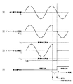
電流検出器12の検出出力(インバータ装置(#1)1の出力ラインに流れる電流)I1(図2(C))は、極性比較器141に入力され、極性比較器141により、電流検出器12により検出されたインバータ装置(#1)1の出力電流I1の極性と、図示してない出力電圧指令を出力する出力制御部からの出力電圧指令値Vi(図2(A))の極性とが比較され、極性比較器141は前記出力電流I1の極性が出力電圧指令値Viに対し逆極性である場合に出力電流I1のレベルを示す信号をレベル比較器142に出力する。因みに、インバータ装置(#1)1の出力電圧VINVは、図2(B)に示すようになる。
The detection output of the current detector 12 (current flowing through the output line of the inverter device (# 1) 1) I1 (FIG. 2C) is input to the
レベル比較器142では、極性比較器141の出力信号と異常判定をするための異常判定閾値±ITH(図2で示す例では、−ITH)とを比較し、極性比較器141の出力信号が異常判定閾値を超える場合に異常判定信号を時間検出器143に出力する。
The
時間検出器143は、レベル比較器142より出力される異常判定信号が予め設定された時間Tが経過する時点まで、継続して出力された場合に、インバータ装置(#1)に内部短絡が発生したと判定し、時刻t2で解列信号SR(図2(D))を解列手段13に出力し、解列手段13を駆動する。
解列手段113は、インバータ装置(#1)1の自機出力を母線3から解列する。
The
Disconnecting means 113 disconnects the output of inverter device (# 1) 1 from
以上に説明したように、本発明の実施形態に係るインバータ装置によれば、インバータ装置の内部短絡等の事故を確実に検出でき、自機を母線から解列することができる。
また、本発明の実施形態に係るインバータシステムによれば、インバータ装置の内部短絡等の事故を確実に検出でき、故障機を母線から解列することができ、システムの信頼性の向上が図れる。
また、故障検出用回路を追加する必要がなく、低コスト化が図れる。
さらに、部品点数削減による信頼性の向上が図れる。
As described above, according to the inverter device according to the embodiment of the present invention, it is possible to reliably detect an accident such as an internal short circuit of the inverter device, and to disconnect the own device from the bus.
In addition, according to the inverter system according to the embodiment of the present invention, it is possible to reliably detect an accident such as an internal short circuit of the inverter device, disconnect the faulty machine from the bus, and improve the reliability of the system.
Further, it is not necessary to add a failure detection circuit, and the cost can be reduced.
Furthermore, the reliability can be improved by reducing the number of parts.
以上、本発明の実施の形態について説明したが、本発明のインバータ装置は、上述の図示例にのみ限定されるものではなく、本発明の要旨を逸脱しない範囲内において種々変更を加え得ることは勿論である。 Although the embodiment of the present invention has been described above, the inverter device of the present invention is not limited to the illustrated example described above, and various modifications can be made without departing from the scope of the present invention. Of course.
1〜n…インバータ装置、3…母線、4−1〜4−n…リレー、11…電力変換装置、12…電流検出器、13…解列手段、14…制御回路、31…DC電源、32…負荷、141…極性比較器、142…レベル比較器、143…時間検出器 DESCRIPTION OF SYMBOLS 1-n ... Inverter device, 3 ... Bus, 4-1-4-n ... Relay, 11 ... Power converter, 12 ... Current detector, 13 ... Disconnection means, 14 ... Control circuit, 31 ... DC power supply, 32 ... Load, 141 ... Polarity comparator, 142 ... Level comparator, 143 ... Time detector
Claims (5)
前記インバータ装置の出力ラインに自機出力を並列母線から解列する解列手段と、
前記インバータ装置の出力ラインに流れる電流を検出する電流検出手段と、
前記電流検出手段により検出された前記インバータ装置の出力電流の極性と自機に与えられた出力電圧指令値の極性とを比較し、予め設定された時間が経過する時点まで予め設定された電流値を超える、前記電圧指令値と逆極性の電流が流れる場合に、自機に内部短絡が発生したと判定し、自機を母線から解列するように前記解列手段を制御する制御手段と、
を有することを特徴とするインバータ装置。 An inverter device used for performing parallel redundant operation of a plurality of units,
Disconnecting means for disconnecting the output of the own device from the parallel bus to the output line of the inverter device;
Current detection means for detecting a current flowing in the output line of the inverter device;
The polarity of the output current of the inverter device detected by the current detection means is compared with the polarity of the output voltage command value given to the own device, and the current value set in advance until the time when the preset time elapses When a current having a polarity opposite to the voltage command value flows, it is determined that an internal short circuit has occurred in the own machine, and the control means for controlling the disconnection means to disconnect the own machine from the bus;
An inverter device comprising:
前記電流検出手段により検出された前記インバータ装置の出力電流の極性と出力電圧指令値の極性とを比較し、前記出力電流の極性が前記出力電圧指令値に対し逆極性である場合に前記出力電流のレベルを示す信号を出力する極性判定手段と、
前記極性判定手段の出力信号と異常判定をするための異常判定閾値とを比較し、前記極性判定手段の出力信号が前記異常判定閾値を超える場合に異常判定信号を出力するレベル判定手段と、
前記レベル判定手段より出力される異常判定信号が予め設定された時間が経過する時点まで、継続して出力された場合に、前記インバータ装置に内部短絡が発生したと判定し、前記解列手段を駆動する時間検出手段と、
を有することを特徴とする請求項1に記載のインバータ装置。 The control means includes
The polarity of the output current of the inverter device detected by the current detection means is compared with the polarity of the output voltage command value. When the polarity of the output current is opposite to the output voltage command value, the output current Polarity determination means for outputting a signal indicating the level of
A level determination unit that compares an output signal of the polarity determination unit with an abnormality determination threshold for determining an abnormality, and outputs an abnormality determination signal when the output signal of the polarity determination unit exceeds the abnormality determination threshold;
When the abnormality determination signal output from the level determination means is continuously output until a preset time has elapsed, it is determined that an internal short circuit has occurred in the inverter device, and the disconnection means is Driving time detection means;
The inverter device according to claim 1, comprising:
Priority Applications (1)
| Application Number | Priority Date | Filing Date | Title |
|---|---|---|---|
| JP2005338694A JP4575876B2 (en) | 2005-11-24 | 2005-11-24 | Inverter device and inverter system |
Applications Claiming Priority (1)
| Application Number | Priority Date | Filing Date | Title |
|---|---|---|---|
| JP2005338694A JP4575876B2 (en) | 2005-11-24 | 2005-11-24 | Inverter device and inverter system |
Publications (2)
| Publication Number | Publication Date |
|---|---|
| JP2007151230A JP2007151230A (en) | 2007-06-14 |
| JP4575876B2 true JP4575876B2 (en) | 2010-11-04 |
Family
ID=38211974
Family Applications (1)
| Application Number | Title | Priority Date | Filing Date |
|---|---|---|---|
| JP2005338694A Active JP4575876B2 (en) | 2005-11-24 | 2005-11-24 | Inverter device and inverter system |
Country Status (1)
| Country | Link |
|---|---|
| JP (1) | JP4575876B2 (en) |
Families Citing this family (2)
| Publication number | Priority date | Publication date | Assignee | Title |
|---|---|---|---|---|
| JP4349465B1 (en) | 2008-03-28 | 2009-10-21 | ダイキン工業株式会社 | Power converter |
| CN108599607A (en) * | 2018-04-24 | 2018-09-28 | 西安理工大学 | A kind of principal and subordinate's redundancy control method of T-type three-level inverter parallel connection |
Citations (3)
| Publication number | Priority date | Publication date | Assignee | Title |
|---|---|---|---|---|
| JPH07298625A (en) * | 1994-04-19 | 1995-11-10 | Sanyo Electric Co Ltd | System interconnection inverter |
| JPH08242540A (en) * | 1995-03-01 | 1996-09-17 | Fuji Electric Co Ltd | Method for disconnecting uninterruptible power supply system |
| JPH09140149A (en) * | 1995-11-09 | 1997-05-27 | Toyo Electric Mfg Co Ltd | Fault detection circuit of parallel operation inverter system apparatus |
-
2005
- 2005-11-24 JP JP2005338694A patent/JP4575876B2/en active Active
Patent Citations (3)
| Publication number | Priority date | Publication date | Assignee | Title |
|---|---|---|---|---|
| JPH07298625A (en) * | 1994-04-19 | 1995-11-10 | Sanyo Electric Co Ltd | System interconnection inverter |
| JPH08242540A (en) * | 1995-03-01 | 1996-09-17 | Fuji Electric Co Ltd | Method for disconnecting uninterruptible power supply system |
| JPH09140149A (en) * | 1995-11-09 | 1997-05-27 | Toyo Electric Mfg Co Ltd | Fault detection circuit of parallel operation inverter system apparatus |
Also Published As
| Publication number | Publication date |
|---|---|
| JP2007151230A (en) | 2007-06-14 |
Similar Documents
| Publication | Publication Date | Title |
|---|---|---|
| JP5849586B2 (en) | 3-level power conversion circuit system | |
| JP6519713B2 (en) | Power converter | |
| JP6075024B2 (en) | Multi-level inverter | |
| CA2903362C (en) | Power conversion device | |
| KR102342101B1 (en) | uninterruptible power system | |
| JP5809029B2 (en) | Uninterruptible power system | |
| CN111771320B (en) | Power supply device | |
| JPWO2009084354A1 (en) | AC motor winding switching device and winding switching system thereof | |
| JP5324066B2 (en) | Semiconductor power converter | |
| JP2015130743A (en) | Power conversion device and failure detection method of power conversion device | |
| JP2008172925A (en) | Backup operation device of matrix converter | |
| JP5882884B2 (en) | Uninterruptible power system | |
| US11644506B2 (en) | Power switch fault detection method and power switch fault detection circuit | |
| JP4059098B2 (en) | AC-AC power converter backup device | |
| JP2015527858A (en) | Motion and control system | |
| JP2007330028A (en) | Power conversion device and protection method for power conversion device | |
| JP2007028752A (en) | Elevator motor controller | |
| JP4575876B2 (en) | Inverter device and inverter system | |
| JP4868575B2 (en) | Power converter | |
| JP5071209B2 (en) | Uninterruptible power system | |
| JP2013247693A (en) | Power converter for motor drive | |
| CN112236931B (en) | Phase failure detection device for power conversion device | |
| JP2005354781A (en) | Uninterruptible power supply device | |
| JP6437122B2 (en) | Inverter control device | |
| JP6023034B2 (en) | Power converter |
Legal Events
| Date | Code | Title | Description |
|---|---|---|---|
| A621 | Written request for application examination |
Free format text: JAPANESE INTERMEDIATE CODE: A621 Effective date: 20070814 |
|
| A977 | Report on retrieval |
Free format text: JAPANESE INTERMEDIATE CODE: A971007 Effective date: 20100426 |
|
| A131 | Notification of reasons for refusal |
Free format text: JAPANESE INTERMEDIATE CODE: A131 Effective date: 20100506 |
|
| A521 | Request for written amendment filed |
Free format text: JAPANESE INTERMEDIATE CODE: A523 Effective date: 20100608 |
|
| TRDD | Decision of grant or rejection written | ||
| A01 | Written decision to grant a patent or to grant a registration (utility model) |
Free format text: JAPANESE INTERMEDIATE CODE: A01 Effective date: 20100803 |
|
| A01 | Written decision to grant a patent or to grant a registration (utility model) |
Free format text: JAPANESE INTERMEDIATE CODE: A01 |
|
| A61 | First payment of annual fees (during grant procedure) |
Free format text: JAPANESE INTERMEDIATE CODE: A61 Effective date: 20100820 |
|
| R150 | Certificate of patent or registration of utility model |
Ref document number: 4575876 Country of ref document: JP Free format text: JAPANESE INTERMEDIATE CODE: R150 Free format text: JAPANESE INTERMEDIATE CODE: R150 |
|
| FPAY | Renewal fee payment (event date is renewal date of database) |
Free format text: PAYMENT UNTIL: 20130827 Year of fee payment: 3 |
|
| R250 | Receipt of annual fees |
Free format text: JAPANESE INTERMEDIATE CODE: R250 |
|
| S111 | Request for change of ownership or part of ownership |
Free format text: JAPANESE INTERMEDIATE CODE: R313117 |
|
| R360 | Written notification for declining of transfer of rights |
Free format text: JAPANESE INTERMEDIATE CODE: R360 |
|
| R370 | Written measure of declining of transfer procedure |
Free format text: JAPANESE INTERMEDIATE CODE: R370 |
|
| R250 | Receipt of annual fees |
Free format text: JAPANESE INTERMEDIATE CODE: R250 |
|
| R250 | Receipt of annual fees |
Free format text: JAPANESE INTERMEDIATE CODE: R250 |