JP3655831B2 - Booster unit, power conditioner, and solar power generation system using them - Google Patents
Booster unit, power conditioner, and solar power generation system using them Download PDFInfo
- Publication number
- JP3655831B2 JP3655831B2 JP2001037367A JP2001037367A JP3655831B2 JP 3655831 B2 JP3655831 B2 JP 3655831B2 JP 2001037367 A JP2001037367 A JP 2001037367A JP 2001037367 A JP2001037367 A JP 2001037367A JP 3655831 B2 JP3655831 B2 JP 3655831B2
- Authority
- JP
- Japan
- Prior art keywords
- power
- solar cell
- output
- unit
- cell array
- Prior art date
- Legal status (The legal status is an assumption and is not a legal conclusion. Google has not performed a legal analysis and makes no representation as to the accuracy of the status listed.)
- Expired - Fee Related
Links
Images


Description
【0001】
【発明の属する技術分野】
この発明は昇圧ユニット、パワーコンディショナ、およびそれらを用いた太陽光発電システムに関し、特に、第2の太陽電池列の出力電圧を昇圧させて第1の太陽電池列の出力電圧に一致させるための昇圧ユニットと、第1の太陽電池列で生成された直流電力および昇圧ユニットの出力電力を交流電力に変換して負荷回路に与えるパワーコンディショナと、それらを用いた太陽光発電システムとに関する。
【0002】
【従来の技術】
太陽電池は、太陽光が照射されている限り、直流電源として動作し直流電力を出力する。太陽電池は、2次電池などの他のエネルギ源を介在しなくてもそれのみで直流電力を出力でき、有害な物質を排出しないため、シンプルでクリーンなエネルギ源として知られている。
【0003】
従来の太陽光発電システムにおいては、太陽電池で生成された直流電力がパワーコンディショナによって交流電力に変換され、一般交流負荷あるいは既存の商用電力系統に供給される。パワーコンディショナには複数の太陽電池ストリングが、接続機能を有した外部装置である接続箱を介して接続される。
【0004】
また、複数の太陽電池ストリングには、直列接続された標準枚数の太陽電池モジュールを含む標準太陽電池ストリングと、直列接続された標準枚数未満の枚数の太陽電池モジュールを含む非標準太陽電池ストリングとが含まれる。
【0005】
たとえば、住宅の屋根上に太陽電池ストリングを設置する場合、屋根の形状や面積によっては日射量の最も多い屋根の南面だけに太陽電池モジュールを配置して太陽電池ストリングを構成することができない場合がある。屋根の南面に配置されなかった太陽電池モジュールは屋根の西面や東面にも配置されて太陽電池ストリングを構成したり、屋根の南面の主要部上に太陽電池モジュールを配置した後の周辺の残余領域に配置された小型の太陽電池モジュールをも含めて太陽電池ストリングが構成される場合がある。すなわち、いくつかの太陽電池ストリングに含まれる太陽電池モジュールの直列枚数が他の太陽電池ストリングに比べて少なくなる場合があり、その場合、太陽電池ストリング間で出力電圧が異なることになる。
【0006】
標準直列枚数の太陽電池モジュールで構成される太陽電池ストリングと標準直列枚数未満の枚数の太陽電池モジュールで構成される太陽電池ストリングとがパワーコンディショナに並列に接続される場合、それぞれの最大電力となる動作電圧が異なるため、合成される電圧−電力特性に基づいてパワーコンディショナが最大電力点追従制御を行なっても、それぞれの最大電力を足し合せた電力を出力することはできず、太陽電池の発電電力を最大限有効に活用することはできない。このような場合、パワーコンディショナの前段に昇圧ユニットを設けて標準太陽電池ストリングと非標準太陽電池ストリングの出力電圧を合せることにより、太陽電池の発電電力を最大限有効に活用することが可能となる。
【0007】
図3は、そのような太陽光発電システムの構成を示す回路ブロック図である。図3において、この太陽光発電システムは、標準太陽電池ストリング31a、非標準太陽電池ストリング31b、昇圧ユニット32、接続箱40、およびパワーコンディショナ45を備える。この図3では、図面の簡略化のために2つの太陽電池ストリング31a,31bのみが示されているが、通常はさらに多くの太陽電池ストリングが含まれることは言うまでもない。
【0008】
標準太陽電池ストリング31aは接続箱40を介してパワーコンディショナ45に接続され、他方、非標準太陽電池ストリング31bは昇圧ユニット32および接続箱40を介してパワーコンディショナ45に接続される。昇圧ユニット32は昇圧回路33および昇圧制御部39を含み、昇圧回路33はリアクトル34、スイッチングトランジスタ35、ダイオード36,37およびコンデンサ38を含む。
【0009】
昇圧制御部39は、図4に示すように、昇圧比設定部51、信号設定演算部52、三角波発生部53、信号比較部54およびゲートドライブ部55を含む。昇圧比設定部51は、標準太陽電池ストリング31aに含まれる太陽電池モジュール数n1と非標準太陽電池ストリング31bに含まれる太陽電池モジュール数n2との比すなわち昇圧比n1/n2を設定する。昇圧比設定部51には、昇圧比を切換えるための切換スイッチが設けられており、予め太陽電池ストリング31a,31bに合せて切換スイッチを手動的に切換えることにより、昇圧比が設定される。
【0010】
昇圧比設定部51で設定された昇圧比に基づいて信号設定演算部52で生成された信号設定値Vtと三角波発生部53で生成された0からVdの振幅値をとる三角波信号φTとが信号比較部54で比較される。信号比較部54は、信号設定値Vtが三角波信号φTのレベルよりも高い時にゲートオフレベルを出力してPWM(パルス幅変調)制御を行なう。信号比較部54の出力パルス信号PSは、ゲートドライブ55を介してスイッチングトランジスタ35のゲートに入力される。
【0011】
接続箱40は、パワーコンディショナ45側から太陽電池ストリング31a,31b側への電流の逆流を防止するための逆流防止ダイオード41,42と、太陽電池ストリング31a,31b側からパワーコンディショナ45側に落雷時の雷サージが侵入するのを防止するための雷サージアブソーバ43と、太陽電池ストリング31a,31b側とパワーコンディショナ45側とを接続/遮断するためのブレーカとを含む。パワーコンディショナ45は、接続箱40を介して与えられた直流電力を商用電力と同一の位相および周波数50または60Hzを持つ交流電力に変換して商用電力系統46に供給する。
【0012】
次に、この太陽光発電システムの動作について説明する。図5は、標準太陽電池ストリング31aおよび非標準太陽電池ストリング31bの出力特性を示す図である。図5において、横軸は太陽電池ストリング31a,31bの出力電圧Vを示し、縦軸は太陽電池ストリング31a,31bの出力電力Pを示している。標準太陽電池ストリング31aの太陽電池モジュールの数n1は非標準太陽電池ストリング31bの太陽電池モジュールの数n2よりも多いので、標準太陽電池ストリング31aの最大出力電力Paおよび最大電力出力時の出力電圧Vaは非標準太陽電池ストリング31bの最大出力電力Pbおよび最大電力出力時の出力電圧Vbよりも大きくなっている(Pa>Pb,Va>Vb)。
【0013】
図6は、標準太陽電池ストリング31aおよび非標準太陽電池ストリング31bの出力特性を合成した特性を示す図である。合成した出力特性では、出力電圧がVbのときに出力電力が最大値Pa+α(<Pa+Pb)となる。昇圧ユニット32を用いない場合は、太陽電池ストリング31a,31bの電力はこの特性でパワーコンディショナ45に入力される。この場合は、標準太陽電池ストリング31aと非標準太陽電池ストリング31bでは、最大電力Pa,Pbを出力する電圧Va,Vbが異なるため、それぞれの最大電力Pa,Pbを足し合せた電力Pa+Pbが出力されず、太陽電池ストリング31a,31bの出力電力を最大限有効に活用することはできない。
【0014】
昇圧ユニット32を用いると、図7に示すように、非標準太陽電池ストリング31bの最大電力Pb出力時の電圧を標準太陽電池ストリング31aの最大電力Pb出力時の電圧Vaに一致させることができる。これにより、2つの太陽電池ストリング31a,31bの最大電力Pa,Pbを足し合せた電力Pa+Pbを出力することが可能となり、太陽電池ストリング31a,31bの出力電力を最大限有効に活用することが可能となる。
【0015】
なお、他に、昇圧ユニットと接続箱機能を有するパワーコンディショナとで構成される太陽光発電システムや、接続箱機能を有する昇圧ユニットとパワーコンディショナとで構成される太陽光発電システムもあるが、基本的な機能は図3に示した太陽光発電システムと同じである。
【0016】
【発明が解決しようとする課題】
しかし、従来の太陽光発電システムでは、標準太陽電池ストリング31aの太陽電池モジュールの数n1と、非標準太陽電池ストリング31bの太陽電池モジュールの数n2とに基づいて、昇圧ユニット32の昇圧比n1/n2をシステム設置時に設定する必要があり、システム設置時の作業が煩雑となる。
【0017】
また、太陽電池モジュールは、種類によって太陽電池セル数が異なり、出力電圧も異なる。したがって、太陽電池モジュールの種類、およびその太陽電池モジュールの直列枚数の組合せのすべてに対応するには、予め多数の昇圧比設定値を準備しておく必要があり、さらに、システム設置時に太陽電池モジュールの種類および直列枚数を確認し、多数の設定値から最適な値を選択することは非常に煩雑となる。
【0018】
また、太陽電池モジュールの種類および直列枚数の組合せに対して最適な昇圧比を設定した場合においても、太陽電池ストリング31a,31b間の電圧比が常に一定であるというわけではない。たとえば太陽電池ストリング31aと31bの設置方向が異なっており、日射や影の影響で非標準太陽電池ストリング31bの素子温度がTsからTs′に変化した場合は、図8に示すように、非標準太陽電池ストリング31bの出力特性も変化する。図8では、非標準太陽電池ストリング31bの最大出力電力がPbからPb′に低下し、最大出力時の電圧がVbからVb′に低下した状態が示される。この場合は、図9に示すように、昇圧後の非標準太陽電池ストリング31bの出力電圧Va′は標準太陽電池ストリング31aの出力電圧Vaよりも低くなり、太陽電池ストリング31a,31bの発電電力を最大限有効に活用することができない。
【0019】
また、昇圧ユニット32の昇圧比の設定値を各太陽電池モジュールの種類および直列枚数の組合せごとの細かい設定値ではなく代表的な設定値で近似した場合は、設定値を多く準備する必要がなく設定時の作業も比較的煩雑ではないが、設定した昇圧比では最大電力となる動作電圧が太陽電池ストリング31a,31b間で異なり、それぞれの最大電力を足し合せた電力を出力することができず、太陽電池ストリング31a,31bの発電電力を最大限有効に活用することはできない。
【0020】
それゆえに、この発明の主たる目的は、設置作業が容易で、効率の向上を図ることが可能な昇圧ユニット、パワーコンディショナ、およびそれらを用いた太陽光発電システムを提供することである。
【0021】
【課題を解決するための手段】
この発明に係る昇圧ユニットは、直列接続された第1の数の太陽電池を含む第1の太陽電池列と、直列接続された第1の数よりも小さな第2の数の太陽電池を含む第2の太陽電池列とに少なくとも接続され、第1および第2の太陽電池列で生成された直流電力を交流電力に変換して負荷回路に与える太陽光発電システムにおいて、第2の太陽電池列の出力電圧を昇圧させて第1の太陽電池列の出力電圧に一致させるための昇圧ユニットであって、第2の太陽電池列の出力電圧を昇圧させるための昇圧比の制御が可能な昇圧回路と、第2の太陽電池列の出力電力を検出する電力検出器と、電力検出器の検出結果に基づいて、第2の太陽電池列の出力電力が増加したか減少したかを示す信号を出力する信号発生回路とを備えたものである。
【0022】
太陽光発電システムは、さらに、信号発生回路の出力信号に基づいて、太陽光発電システムの出力電力が最大になるように昇圧回路の昇圧比を制御する制御手段を備え、昇圧ユニットは、さらに、昇圧回路の昇圧比を予め定められた値に設定する設定手段と、制御手段および設定手段のうちのいずれか一方を選択するための選択手段とを備える。
【0023】
また好ましくは、さらに、昇圧回路の出力電圧が予め定められた値を超えたことに応じて昇圧回路の昇圧動作を停止させる保護手段が設けられる。
【0024】
また好ましくは、さらに、電力検出器の検出結果に基づいて、第2の太陽電池列の出力電力を表示するための表示手段が設けられる。
【0025】
また、この発明に係るパワーコンディショナは、直列接続された第1の数の太陽電池を含む第1の太陽電池列と、直列接続された第1の数よりも小さな第2の数の太陽電池を含む第2の太陽電池列に接続され、第2の太陽電池列の出力電圧を昇圧させて第1の太陽電池列の出力電圧に一致させるための昇圧比の制御が可能な昇圧ユニットとに少なくとも接続され、第1の太陽電池列で生成された直流電力および昇圧ユニットの出力電力を交流電力に変換して負荷回路に与えるパワーコンディショナであって、第1の太陽電池列の出力電力と昇圧ユニットの出力電力とを合成し、合成した直流電力を交流電力に変換して負荷回路に与えるインバータ回路と、インバータ回路の出力電力を検出する第1の電力検出器と、第1の電力検出器の検出結果に基づいて、パワーコンディショナの出力電力が最大になるように昇圧ユニットおよびインバータ回路を制御する制御手段を備えたものである。
【0026】
昇圧ユニットは、さらに、第2の太陽電池列の出力電力を検出する第2の電力検出器と、第2の電力検出器の検出結果に基づいて、第2の太陽電池列の出力電力が増加したか減少したかを示す信号を出力する信号発生回路とを含み、制御手段は、信号発生回路の出力信号に基づいて昇圧ユニットの昇圧比を制御する。
【0027】
また、制御手段は、昇圧ユニットの入力電圧が一定に保持されている期間にインバータ回路の出力電力が増加するようにインバータ回路の入力電圧を制御する第1のステップと、インバータ回路の入力電圧が一定に保持されている期間に第2の太陽電池列の出力電力が増加するように昇圧ユニットの昇圧比を制御する第2のステップとを含む。
【0028】
また、この発明に係る太陽光発電システムは、直列接続された第1の数の太陽電池を含む第1の太陽電池列と、直列接続された第1の数よりも小さな第2の数の太陽電池を含む第2の太陽電池列とに少なくとも接続され、第1および第2の太陽電池列で生成された直流電力を交流電力に変換して負荷回路に与える太陽光発電システムであって、第2の太陽電池列の出力電圧を昇圧させて第1の太陽電池列の出力電圧に一致させるための昇圧比の制御が可能な昇圧ユニットと、第1の太陽電池列の出力電力と昇圧ユニットの出力電力とを合成し、合成した直流電力を交流電力に変換して負荷回路に与えるインバータ回路、および太陽光発電システムの出力電力が最大になるように昇圧ユニットおよびインバータ回路を制御する制御手段を含むパワーコンディショナとを備えたものである。
【0029】
制御手段は、昇圧ユニットの入力電圧が一定に保持されている期間にインバータ回路の出力電力が増加するようにインバータ回路の入力電圧を制御する第1のステップと、インバータ回路の入力電圧が一定に保持されている期間に第2の太陽電池列の出力電力が増加するように昇圧ユニットの昇圧比を制御する第2のステップとを含む。
【0030】
また好ましくは、さらに、昇圧ユニットの昇圧比を予め定められた値に設定する設定手段と、制御手段および設定手段のうちのいずれか一方を選択するための選択手段とが設けられ、昇圧ユニットの昇圧比は、選択手段によって選択された制御手段または設定手段によって制御または設定される。
【0031】
また好ましくは、さらに、昇圧ユニットの出力電圧が予め定められた値を超えたことに応じて昇圧ユニットの昇圧動作を停止させる保護手段が設けられる。
【0032】
また好ましくは、さらに、第2の太陽電池列の出力電力を表示するための表示手段が設けられる。
【0033】
【発明の実施の形態】
図1は、この発明の一実施の形態による太陽光発電システムの構成を示すブロック図である。図1において、この太陽光発電システムは、標準太陽電池ストリング1a、非標準太陽電池ストリング1b、パワーコンディショナ2および昇圧ユニット10を備える。図1では、図面の簡略化のために1つの標準太陽電池ストリング1aと1つの非標準太陽電池ストリング1bのみが示されているが、さらに多くの太陽電池ストリングが含まれ得ることはいうまでもない。標準太陽電池ストリング1aは、標準直列枚数(通常8枚または9枚)の太陽電池モジュールを含んでいる。非標準太陽電池ストリング1bは、標準直列枚数未満の枚数の太陽電池モジュールを含んでいる。
【0034】
パワーコンディショナ2は、逆流防止ダイオード3,4、インバータ回路5、インバータ制御部6、出力電流検出器7、入力電圧検出器8、昇圧ユニット制御部9を含む。標準太陽電池ストリング1aの出力電圧は、逆流防止ダイオード3を介してインバータ回路5に入力される。非標準太陽電池ストリング1bの出力電圧は、昇圧ユニット10および逆流防止ダイオード4を介してインバータ回路5に入力される。インバータ回路5は、インバータ制御部6によって制御され、直流電力を商用電力と同一の位相および周波数50または60Hzを持つ交流電力に変換し、商用電力系統22に供給する。
【0035】
パワーコンディショナ2の出力電流IOは出力電流検出器7によって検出され、また、パワーコンディショナ2の入力電圧VAは入力電圧検出器8によって検出されて、インバータ制御部6に入力される。インバータ制御部6は、出力電流検出値IOと入力電圧検出値VAとに基づいて、出力電流IOが最大になるようにインバータ回路5を制御することにより、インバータ回路5の出力電力が最大になるように制御している。昇圧ユニット10を運転していない場合は、図5〜図7で示したように、標準太陽電池ストリング1aの出力電力が最大になっている。ここで、非標準太陽電池ストリング1bの出力電力が最大になるように制御すれば、それぞれの最大電力を足し合せた電力を出力できることになり、太陽電池ストリング1a,1bの発電電力を最大限有効に活用することが可能となる。
【0036】
昇圧ユニット制御部9は、昇圧ユニット10に対し、昇圧比を制御し、デューティを与えることにより、非標準太陽電池ストリング1bの出力電力が最大になるように昇圧ユニット10を制御する。すなわち、昇圧ユニット制御部9は、目標となる昇圧ユニット入力電圧設定値VBrefを持ち、非標準太陽電池ストリング1bの出力電力が増加方向になるように目標入力電圧設定値VBrefを変化させる。また、パワーコンディショナ入力電圧VAを検出し、昇圧ユニット入力電圧設定値VBrefから昇圧比VA/VBrefを決定し、その昇圧比からデューティ1−VBref/VAを算出して昇圧ユニット10に与える。
【0037】
昇圧ユニット10は、昇圧回路11、昇圧制御部17、入力電圧検出器18、出力電圧検出器19、入力電流検出器20および表示部21を含む。昇圧回路11は、リアクトル12、スイッチングトランジスタ13、ダイオード14,15およびコンデンサ16を含む。非標準太陽電池ストリング1bで生成された直流電力は、リアクトル12を介してスイッチングトランジスタ13に入力される。スイッチングトランジスタ13のオン期間にリアクトル12に蓄えられたエネルギがスイッチングトランジスタ13のオフ期間にダイオード14を介してコンデンサ16に蓄えられ出力される。つまり、スイッチングトランジスタ13のオン/オフ制御によって昇圧回路11の出力電圧が制御される。昇圧ユニット10とパワーコンディショナ2の間は信号線によって接続され、互いの制御部9,17間で通信可能となっている。
【0038】
昇圧制御部17は、パワーコンディショナ2の昇圧ユニット制御部9から与えられたデューティで昇圧回路11のスイッチングトランジスタ13をオン/オフさせる。また、昇圧制御部17は、入力電圧VBおよび入力電流IBをそれぞれ検出器18,20を介して検出し、昇圧ユニット10の入力電力(非標準太陽電池ストリング1bの出力電力)を算出し、入力電力が増加したか減少したかを示す信号をパワーコンディショナ2の昇圧ユニット制御部9に与える。表示部21は、昇圧制御部17で算出された瞬時電力や昇圧回路11の運転状態を表示する。また、昇圧制御部17は、検出器19を介して検出した昇圧ユニット10の出力電圧VCが予め定められた値以上にならないように監視し、その値を超えた場合は過電圧保護のため昇圧回路11の昇圧動作を停止させる。
【0039】
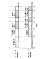
図2は、この太陽光発電システムの動作を示すタイムチャートである。パワーコンディショナ2が時刻T0から連系運転を開始すると、まず、インバータ制御部6において初期動作が開始される。この初期動作期間では、パワーコンディショナ入力電圧VAが予め設定された初期値VAref(T0)に達するまで出力を増加させる。この期間T0〜T1において昇圧ユニット制御部9は動作しておらず、昇圧ユニット10は停止している。入力電圧VAが予め設定された初期値VAref(T0)に達すると、インバータ制御部6はこの電圧を維持するようにインバータ回路5を制御する。一方、昇圧ユニット制御部9は、時刻T1から初期動作を開始する。昇圧ユニット制御部9の初期動作期間では、パワーコンディショナ入力電圧VAと予め設定されている昇圧ユニット入力電圧の初期値VBref(T0)とに基づいて昇圧比VA(T)/VBref(T0)が求められ、さらに、デューティ1−VBref(T0)/VA(T)が求められ、そのデューティと運転許可信号とが昇圧ユニット10に与えられる。昇圧ユニット10は、昇圧ユニット制御部9から運転許可信号およびデューティが与えられると、動作を開始し、デューティを徐々に変化させてスイッチングトランジスタ13のオン時間を増加させ、デューティを1−VBref(T0)/VA(T)にする。ここで、VA(T)は時々刻々変化するパワーコンディショナ入力電圧を示している。これは、時刻T1〜T2の間はインバータ制御部6がパワーコンディショナ入力電圧を一定に保つように制御しているが、昇圧ユニット10の出力電力の変化によって電圧が変化するからである。昇圧ユニット10のデューティが1−VBref(T0)/VA(T)に達した時点T2で、昇圧ユニット10からパワーコンディショナ2に検出電力が増加したか減少したかを示す信号が与えられる。なお、初期動作期間では、電力が0の状態から開始されるので電力は必ず増加する。
【0040】
次に、インバータ制御部6は、最大電力点追従動作(MPPT)を開始する。時刻T2〜T3の間は、昇圧ユニット制御部9がデューティ1−VBref(T0)/VA(T)を昇圧ユニット10に与え続けるので、インバータ制御部6の最大電力点追従動作でパワーコンディショナ入力電圧VAが変動しても、昇圧ユニット入力電圧VBが一定に保たれる。したがって、昇圧ユニット10の出力電力が一定に保たれるので、インバータ制御部6の最大電力点追従動作が高精度で行われる。時刻T2〜T3におけるインバータ制御部6の最大電力点追従動作では、パワーコンディショナ出力電流IOが増加する方向が調べられ、パワーコンディショナ出力電流IOが増加する方向へ入力電圧設定値VAref(T0)がVAref(T3)に更新される。
【0041】
パワーコンディショナ入力電圧VAが入力電圧設定値VAref(T3)に達した時刻(T3)からは、最大電力点追従動作は昇圧ユニット制御部9に移り、インバータ制御部6は入力電圧VAが入力電圧設定値VAref(T3)を維持するようにインバータ回路6を制御する。一方、昇圧ユニット制御部9は、昇圧ユニット10から電力が増加したか減少したかを示す信号を受け、その信号に基づいて昇圧ユニット10の電力が増加する方向に入力電圧設定値をVBref(T0)からVBref(T4)に更新し、デューティ1−VBref(T4)/VA(T)を昇圧ユニット10に与える。昇圧ユニット10は、昇圧ユニット制御部9から与えられたデューティで動作する。時刻T4から最大電力点追従動作は、インバータ制御部6に移る。このように、最大電力点追従制御をインバータ制御部6と昇圧ユニット制御部9で交互に繰返し実行することにより、太陽電池ストリング1a,1bそれぞれの最大電力を出力させることが可能となる。
【0042】
なお、昇圧ユニット10の昇圧制御部17に昇圧比を手動設定と昇圧ユニット制御部9による自動制御とのうちのいずれかに切換えるための切換スイッチを設ければ、既存のパワーコンディショナ2に昇圧ユニット10を追加する場合のようにパワーコンディショナ2に昇圧ユニット10との通信機能がない場合において、予め標準直列枚数と非標準直列枚数により設定された昇圧比で昇圧ユニット10を動作させることが可能となり、より多くのシステムに対応することができる。また、その切換スイッチが、パワーコンディショナ2と昇圧ユニット10との通信機能の有無に応じて自動的に切換えられるようにしてもよい。
【0043】
また、この実施の形態では、昇圧回路11の出力電圧VCが所定値を超えた場合は過電圧保護のため昇圧回路11の昇圧動作を停止させたが、インバータ回路5の入力電圧VAが所定値を超えた場合に昇圧回路11の昇圧動作を停止させてもよい。
【0044】
今回開示された実施の形態はすべての点で例示であって制限的なものではないと考えられるべきである。本発明の範囲は上記した説明ではなくて特許請求の範囲によって示され、特許請求の範囲と均等の意味および範囲内でのすべての変更が含まれることが意図される。
【0045】
【発明の効果】
以上のように、この発明に係る昇圧ユニットでは、第2の太陽電池列の出力電圧を昇圧させるための昇圧比の制御が可能な昇圧回路と、第2の太陽電池列の出力電力を検出する電力検出器と、電力検出器の検出結果に基づいて、第2の太陽電池列の出力電力が増加したか減少したかを示す信号を出力する信号発生回路とが設けられる。したがって、信号発生回路の出力信号に基づいてシステムの出力電力が最大になるように昇圧回路の昇圧比を制御できるので、従来のように昇圧回路の昇圧比を手動で設定する必要がなくなり、システム設定時の作業が容易になる。また、第1および第2の太陽電池列のうちの一方の出力電圧が日射の影響などにより変化した場合でも、それに応じて昇圧回路の昇圧比を最適値に制御できるので、昇圧比が一定値に固定されていた従来に比べ効率が高くなる。
【0046】
また、太陽光発電システムは、さらに、信号発生回路の出力信号に基づいて、太陽光発電システムの出力電力が最大になるように昇圧回路の昇圧比を制御する制御手段を備え、昇圧ユニットは、さらに、昇圧回路の昇圧比を予め定められた値に設定する設定手段と、制御手段および設定手段のうちのいずれか一方を選択するための選択手段とを備える。したがって、第2の太陽電池列を増設する場合に便利である。
【0047】
また好ましくは、さらに、昇圧回路の出力電圧が予め定められた値を超えたことに応じて昇圧回路の昇圧動作を停止させる保護手段が設けられる。この場合は、昇圧回路の出力電圧が高くなりすぎてシステムが破壊されるのを防止することができる。
【0048】
また好ましくは、さらに、電力検出器の検出結果に基づいて、第2の太陽電池列の出力電力を表示するための表示手段が設けられる。この場合は、第2の太陽電池列の出力電力を確認することができ便利である。
【0049】
また、この発明に係るパワーコンディショナでは、第1の太陽電池列の出力電力と昇圧ユニットの出力電力とを合成し、合成した直流電力を交流電力に変換して負荷回路に与えるインバータ回路と、インバータ回路の出力電力を検出する第1の電力検出器と、第1の電力検出器の検出結果に基づいて、パワーコンディショナの出力電力が最大になるように昇圧ユニットおよびインバータ回路を制御する制御手段とが設けられる。したがって、第1の電力検出器の検出結果に基づいてパワーコンディショナの出力電力が最大になるように昇圧ユニットおよびインバータ回路を制御するので、従来のように昇圧ユニットの昇圧比を手動で設定する必要がなくなり、システム設定時の作業が容易になる。また、第1および第2の太陽電池列のうちの一方の出力電圧が日射の影響などにより変化した場合でも、それに応じて昇圧ユニットの昇圧比を最適値に制御できるので、昇圧比が一定値に固定されていた従来に比べ効率が高くなる。
【0050】
また、昇圧ユニットは、さらに、第2の太陽電池列の出力電力を検出する第2の電力検出器と、第2の電力検出器の検出結果に基づいて、第2の太陽電池列の出力電力が増加したか減少したかを示す信号を出力する信号発生回路とを含み、制御手段は、信号発生回路の出力信号に基づいて昇圧ユニットの昇圧比を制御する。これにより、昇圧ユニットの昇圧比を容易に制御することができる。
【0051】
また、制御手段は、昇圧ユニットの入力電圧が一定に保持されている期間にインバータ回路の出力電力が増加するようにインバータ回路の入力電圧を制御する第1のステップと、インバータ回路の入力電圧が一定に保持されている期間に第2の太陽電池列の出力電力が増加するように昇圧ユニットの昇圧比を制御する第2のステップとを含む。したがって、昇圧ユニットの昇圧比とインバータ回路とを交互に制御するので、それらの制御を容易かつ確実に行なうことができる。
【0052】
また、この発明に係る太陽光発電システムでは、第2の太陽電池列の出力電圧を昇圧させるための昇圧ユニットと、第1の太陽電池列の出力電力と昇圧ユニットの出力電力とを合成し、合成した直流電力を交流電力に変換するためのインバータ回路とおよび太陽光発電システムの出力電力が最大になるように昇圧ユニットおよびインバータ回路を制御する制御手段を含むパワーコンディショナとが設けられる。したがって、システムの出力電力が最大になるように昇圧ユニットの昇圧比が制御手段によって制御されるので、従来のように昇圧ユニットの昇圧比を手動で設定する必要がなくなり、システム設定時の作業が容易になる。また、第1および第2の太陽電池列のうちの一方の出力電圧が日射の影響などにより変化した場合でも、それに応じて昇圧ユニットの昇圧比が最適値に制御されるので、昇圧比が一定値に固定されていた従来に比べて効率が高くなる。
【0053】
また、制御手段は、昇圧ユニットの入力電圧が一定に保持されている期間にインバータ回路の出力電力が増加するようにインバータ回路の入力電圧を制御する第1ステップと、インバータ回路の入力電圧が一定に保持されている期間に第2の太陽電池列の出力電力が増加するように昇圧ユニットの昇圧比を制御する第2のステップとを含む。したがって、昇圧ユニットの昇圧比とインバータ回路とを交互に制御するので、それらの制御を容易かつ確実に行なうことができる。
【0054】
好ましくは、さらに、昇圧ユニットの昇圧比を予め定められた値に設定する設定手段と、制御手段および設定手段のうちのいずれか一方を選択するための選択手段が設けられ、昇圧ユニットの昇圧比は、選択手段によって選択された制御手段または設定手段によって制御または設定される。この場合は、第2の太陽電池列を増設する場合に好適である。
【0055】
また好ましくは、さらに、昇圧ユニットの出力電圧が予め定められた値を超えたことに応じて昇圧ユニットの昇圧動作を停止させる保護手段が設けられる。この場合は、昇圧ユニットの出力電圧が高くなりすぎてインバータ回路などが破壊されるのを防止することができる。
【0056】
また好ましくは、さらに、第2の太陽電池列の出力電力を表示するための表示手段が設けられる。この場合は、第2の太陽電池列の出力電力を確認することができ便利である。
【図面の簡単な説明】
【図1】 この発明の一実施の形態による太陽光発電システムの構成を示す回路ブロック図である。
【図2】 図1に示した太陽光発電システムの動作を説明するためのタイムチャートである。
【図3】 従来の太陽光発電システムの構成を示す回路ブロック図である。
【図4】 図3に示した昇圧制御部の構成を示すブロック図である。
【図5】 図3に示した太陽光発電システムの動作を説明するための図である。
【図6】 図3に示した太陽光発電システムの動作を説明するための他の図である。
【図7】 図3に示した太陽光発電システムの動作を説明するためのさらに他の図である。
【図8】 図3に示した太陽光発電システムの問題点を説明するための図である。
【図9】 図3に示した太陽光発電システムの問題点を説明するための他の図である。
【符号の説明】
1a,31a 標準太陽電池ストリング、1b,31b 非標準太陽電池ストリング、2,45 パワーコンディショナ、3,4,14,15,36,37,41,42 ダイオード、5 インバータ回路、6 インバータ制御部、7,20 電流検出器、8,18,19 電圧検出器、9 昇圧ユニット制御部、10,32 昇圧ユニット、11,33 昇圧回路、12,34 リアクトル、13,35 スイッチングトランジスタ、16,38 コンデンサ、17,39 昇圧制御部、21 表示部、22,46 商用電力系統、40 接続箱、43 雷サージアブソーバ、44 ブレーカ、51 昇圧比設定部、52 信号設定演算部、53 三角波発生部、54 信号比較部、55 ゲートドライブ部。[0001]
BACKGROUND OF THE INVENTION
The present invention relates to a boosting unit, a power conditioner, and a photovoltaic power generation system using them, and more particularly, for boosting the output voltage of a second solar cell array to match the output voltage of the first solar cell array The present invention relates to a booster unit, a power conditioner that converts DC power generated by a first solar cell array and output power of the booster unit into AC power and supplies the AC power to a load circuit, and a solar power generation system using them.
[0002]
[Prior art]
As long as sunlight is irradiated, the solar cell operates as a DC power source and outputs DC power. A solar cell is known as a simple and clean energy source because it can output direct-current power without any other energy source such as a secondary battery and does not discharge harmful substances.
[0003]
In a conventional solar power generation system, DC power generated by a solar cell is converted into AC power by a power conditioner and supplied to a general AC load or an existing commercial power system. A plurality of solar cell strings are connected to the inverter through a connection box that is an external device having a connection function.
[0004]
The plurality of solar cell strings include a standard solar cell string including a standard number of solar cell modules connected in series and a non-standard solar cell string including less than the standard number of solar cell modules connected in series. included.
[0005]
For example, when installing a solar cell string on the roof of a house, depending on the shape and area of the roof, it may not be possible to configure the solar cell string by arranging solar cell modules only on the south surface of the roof with the highest amount of solar radiation. is there. Solar cell modules that were not placed on the south side of the roof were also placed on the west and east sides of the roof to form a solar cell string, or after the solar cell module was placed on the main part of the south side of the roof. A solar cell string may be configured including a small solar cell module arranged in the remaining region. That is, the number of solar cell modules included in some solar cell strings may be smaller than that of other solar cell strings, and in this case, the output voltage differs between the solar cell strings.
[0006]
When a solar cell string composed of a standard series number of solar cell modules and a solar cell string composed of less than the standard series number of solar cell modules are connected in parallel to the power conditioner, Therefore, even if the power conditioner performs maximum power point tracking control based on the synthesized voltage-power characteristics, it is not possible to output power that is the sum of the maximum powers. It is not possible to make the best use of the generated power. In such a case, it is possible to make the most effective use of the power generated by the solar cell by providing a booster unit in front of the inverter and combining the output voltages of the standard solar cell string and the non-standard solar cell string. Become.
[0007]
FIG. 3 is a circuit block diagram showing the configuration of such a photovoltaic power generation system. In FIG. 3, the photovoltaic power generation system includes a standard
[0008]
The standard
[0009]
As shown in FIG. 4, the
[0010]
Based on the boost ratio set by the boost
[0011]
The
[0012]
Next, the operation of this solar power generation system will be described. FIG. 5 is a diagram showing output characteristics of the standard
[0013]
FIG. 6 is a diagram showing characteristics obtained by synthesizing the output characteristics of the standard
[0014]
When the
[0015]
In addition, there are also a photovoltaic power generation system composed of a booster unit and a power conditioner having a junction box function, and a photovoltaic power generation system composed of a booster unit having a junction box function and a power conditioner. The basic function is the same as that of the photovoltaic power generation system shown in FIG.
[0016]
[Problems to be solved by the invention]
However, in the conventional photovoltaic power generation system, based on the number n1 of solar cell modules of the standard
[0017]
Moreover, the solar cell module differs in the number of solar cells depending on the type, and the output voltage also differs. Therefore, in order to deal with all types of solar cell modules and combinations of the number of solar cell modules in series, it is necessary to prepare a large number of step-up ratio setting values in advance. It is very troublesome to check the type and the number in series and select an optimum value from a large number of set values.
[0018]
Further, even when the optimum step-up ratio is set for the combination of the types of solar cell modules and the number of serially connected modules, the voltage ratio between the
[0019]
Further, when the set value of the boost ratio of the
[0020]
Therefore, a main object of the present invention is to provide a booster unit, a power conditioner, and a solar power generation system using them that are easy to install and can improve efficiency.
[0021]
[Means for Solving the Problems]
The step-up unit according to the present invention includes a first solar cell array including a first number of solar cells connected in series, and a second number of solar cells smaller than the first number connected in series. In a solar power generation system that is connected to at least two solar cell columns and converts DC power generated by the first and second solar cell columns to AC power and supplies the AC power to a load circuit, the second solar cell column A boosting unit for boosting the output voltage to match the output voltage of the first solar cell array, and a booster circuit capable of controlling the boost ratio for boosting the output voltage of the second solar cell array; A power detector for detecting the output power of the second solar cell array, and a signal indicating whether the output power of the second solar cell array has increased or decreased based on the detection result of the power detector. And a signal generation circuit.
[0022]
Thick The positive power generation system further includes control means for controlling the boost ratio of the booster circuit so that the output power of the photovoltaic power generation system is maximized based on the output signal of the signal generation circuit, and the booster unit further includes a booster Setting means for setting the step-up ratio of the circuit to a predetermined value, and selection means for selecting any one of the control means and the setting means are provided.
[0023]
Preferably, further, a protection unit is provided for stopping the boosting operation of the booster circuit when the output voltage of the booster circuit exceeds a predetermined value.
[0024]
Further preferably, a display means for displaying the output power of the second solar cell array based on the detection result of the power detector is further provided.
[0025]
The power conditioner according to the present invention includes a first solar cell array including a first number of solar cells connected in series, and a second number of solar cells smaller than the first number connected in series. And a step-up unit capable of controlling the step-up ratio for boosting the output voltage of the second solar cell row to coincide with the output voltage of the first solar cell row. A power conditioner that is connected at least and that converts DC power generated by the first solar cell array and output power of the boost unit to AC power and supplies the AC power to a load circuit, the output power of the first solar array An inverter circuit that combines the output power of the boosting unit, converts the combined DC power into AC power, and applies it to the load circuit, a first power detector that detects the output power of the inverter circuit, and a first power detection Detector detection Based on the output power of the power conditioner are those having a control unit for controlling the booster unit and the inverter circuit so as to maximize.
[0026]
Ascension The pressure unit further increases the output power of the second solar cell array based on the second power detector that detects the output power of the second solar battery array and the detection result of the second power detector. And a signal generating circuit for outputting a signal indicating whether the voltage has been reduced or not, and the control means controls the boosting ratio of the boosting unit based on the output signal of the signal generating circuit.
[0027]
Ma The The control means includes a first step of controlling the input voltage of the inverter circuit so that the output power of the inverter circuit increases while the input voltage of the boosting unit is held constant, and the input voltage of the inverter circuit is constant. And a second step of controlling the boosting ratio of the boosting unit so that the output power of the second solar cell array increases during the held period.
[0028]
Moreover, the solar power generation system according to the present invention includes a first solar cell array including a first number of solar cells connected in series, and a second number of solar cells smaller than the first number connected in series. A photovoltaic power generation system that is connected to at least a second solar cell array including a battery, converts DC power generated by the first and second solar cell columns into AC power, and supplies the AC power to a load circuit; A step-up unit capable of controlling the step-up ratio for boosting the output voltage of the second solar cell array to match the output voltage of the first solar cell array, and the output power of the first solar cell array and the boost unit An inverter circuit that combines output power and converts the combined DC power to AC power and supplies it to the load circuit, and control means for controlling the boosting unit and the inverter circuit so that the output power of the photovoltaic power generation system is maximized Including It is obtained by a chromatography conditioner.
[0029]
System The control means includes a first step of controlling the input voltage of the inverter circuit so that the output power of the inverter circuit increases while the input voltage of the boosting unit is held constant, and the input voltage of the inverter circuit is constant. And a second step of controlling the boosting ratio of the boosting unit so that the output power of the second solar cell array increases during the held period.
[0030]
Further preferably, there is further provided a setting means for setting the boosting ratio of the boosting unit to a predetermined value, and a selecting means for selecting one of the control means and the setting means. The step-up ratio is controlled or set by the control means or setting means selected by the selection means.
[0031]
Preferably, further, a protection unit is provided for stopping the boosting operation of the boosting unit when the output voltage of the boosting unit exceeds a predetermined value.
[0032]
Preferably, a display means for displaying the output power of the second solar cell array is further provided.
[0033]
DETAILED DESCRIPTION OF THE INVENTION
FIG. 1 is a block diagram showing a configuration of a photovoltaic power generation system according to an embodiment of the present invention. In FIG. 1, this photovoltaic power generation system includes a standard
[0034]
The
[0035]
The output current IO of the
[0036]
The step-up
[0037]
The step-up
[0038]
The step-up
[0039]
FIG. 2 is a time chart showing the operation of this solar power generation system. When the
[0040]
Next, the
[0041]
From the time (T3) when the inverter input voltage VA reaches the input voltage set value VAref (T3), the maximum power point tracking operation moves to the boosting
[0042]
Note that if the
[0043]
In this embodiment, when the output voltage VC of the
[0044]
The embodiment disclosed this time should be considered as illustrative in all points and not restrictive. The scope of the present invention is defined by the terms of the claims, rather than the description above, and is intended to include any modifications within the scope and meaning equivalent to the terms of the claims.
[0045]
【The invention's effect】
As described above, in the boosting unit according to the present invention, the booster circuit capable of controlling the boosting ratio for boosting the output voltage of the second solar cell array and the output power of the second solar cell array are detected. A power detector and a signal generation circuit that outputs a signal indicating whether the output power of the second solar cell array has increased or decreased based on the detection result of the power detector are provided. Therefore, the boost ratio of the booster circuit can be controlled so that the output power of the system is maximized based on the output signal of the signal generation circuit, so there is no need to manually set the boost ratio of the booster circuit as in the prior art. Work at the time of setting becomes easy. Even when the output voltage of one of the first and second solar cell arrays changes due to the influence of solar radiation, the boost ratio of the booster circuit can be controlled to the optimum value accordingly, so that the boost ratio is a constant value. The efficiency is higher than in the conventional case.
[0046]
Also The photovoltaic power generation system further includes control means for controlling the boosting ratio of the boosting circuit so that the output power of the photovoltaic power generation system is maximized based on the output signal of the signal generating circuit, and the boosting unit further includes And a setting means for setting the boosting ratio of the boosting circuit to a predetermined value, and a selection means for selecting one of the control means and the setting means. Therefore This is convenient when adding a second solar cell array.
[0047]
Preferably, further, a protection unit is provided for stopping the boosting operation of the booster circuit when the output voltage of the booster circuit exceeds a predetermined value. In this case, it is possible to prevent the output voltage of the booster circuit from becoming too high and destroying the system.
[0048]
Further preferably, a display means for displaying the output power of the second solar cell array based on the detection result of the power detector is further provided. In this case, the output power of the second solar cell array can be confirmed, which is convenient.
[0049]
Further, in the power conditioner according to the present invention, an inverter circuit that combines the output power of the first solar cell array and the output power of the boosting unit, converts the combined DC power into AC power, and supplies the AC power to the load circuit; A first power detector that detects the output power of the inverter circuit, and a control that controls the boost unit and the inverter circuit so that the output power of the power conditioner is maximized based on the detection result of the first power detector. Means. Therefore, since the booster unit and the inverter circuit are controlled based on the detection result of the first power detector so as to maximize the output power of the power conditioner, the booster ratio of the booster unit is manually set as in the prior art. Eliminates the need for system setup. Further, even when the output voltage of one of the first and second solar cell arrays changes due to the influence of solar radiation, the boost ratio of the boost unit can be controlled to the optimum value accordingly, so that the boost ratio is a constant value. The efficiency is higher than in the conventional case.
[0050]
Also The boosting unit further includes a second power detector that detects the output power of the second solar cell array, and the output power of the second solar cell array based on the detection result of the second power detector. And a signal generating circuit for outputting a signal indicating whether the voltage has increased or decreased, and the control means controls the boosting ratio of the boosting unit based on the output signal of the signal generating circuit. This By The boost ratio of the boost unit can be easily controlled.
[0051]
Ma The The control means includes a first step of controlling the input voltage of the inverter circuit so that the output power of the inverter circuit increases while the input voltage of the boosting unit is held constant, and the input voltage of the inverter circuit is constant. And a second step of controlling the boosting ratio of the boosting unit so that the output power of the second solar cell array increases during the held period. Therefore Since the boosting ratio of the boosting unit and the inverter circuit are controlled alternately, these controls can be performed easily and reliably.
[0052]
Further, in the photovoltaic power generation system according to the present invention, the boosting unit for boosting the output voltage of the second solar cell array, the output power of the first solar cell array and the output power of the boosting unit are combined, An inverter circuit for converting the combined DC power into AC power and a power conditioner including control means for controlling the boosting unit and the inverter circuit so as to maximize the output power of the photovoltaic power generation system are provided. Therefore, since the boosting ratio of the boosting unit is controlled by the control means so that the output power of the system is maximized, there is no need to manually set the boosting ratio of the boosting unit as in the prior art. It becomes easy. Even when the output voltage of one of the first and second solar cell rows changes due to the influence of solar radiation, the boost ratio of the boost unit is controlled to the optimum value accordingly, so that the boost ratio is constant. The efficiency is higher than the conventional case where the value is fixed.
[0053]
Also The control means includes a first step of controlling the input voltage of the inverter circuit so that the output power of the inverter circuit increases during a period in which the input voltage of the boosting unit is held constant, and the input voltage of the inverter circuit is made constant And a second step of controlling the boosting ratio of the boosting unit so that the output power of the second solar cell array increases during the held period. Therefore Since the boosting ratio of the boosting unit and the inverter circuit are controlled alternately, these controls can be performed easily and reliably.
[0054]
Preferably, there is further provided a setting means for setting the boosting ratio of the boosting unit to a predetermined value, and a selecting means for selecting one of the control means and the setting means, and the boosting ratio of the boosting unit is provided. Are controlled or set by the control means or setting means selected by the selection means. This case is suitable for adding a second solar cell array.
[0055]
Preferably, further, a protection unit is provided for stopping the boosting operation of the boosting unit when the output voltage of the boosting unit exceeds a predetermined value. In this case, it is possible to prevent the output voltage of the boosting unit from becoming too high and destroying the inverter circuit or the like.
[0056]
Preferably, a display means for displaying the output power of the second solar cell array is further provided. In this case, the output power of the second solar cell array can be confirmed, which is convenient.
[Brief description of the drawings]
FIG. 1 is a circuit block diagram showing a configuration of a photovoltaic power generation system according to an embodiment of the present invention.
FIG. 2 is a time chart for explaining the operation of the photovoltaic power generation system shown in FIG. 1;
FIG. 3 is a circuit block diagram showing a configuration of a conventional photovoltaic power generation system.
4 is a block diagram showing a configuration of a boost control unit shown in FIG. 3. FIG.
5 is a diagram for explaining the operation of the photovoltaic power generation system shown in FIG. 3. FIG.
6 is another diagram for explaining the operation of the photovoltaic power generation system shown in FIG. 3. FIG.
7 is still another diagram for explaining the operation of the photovoltaic power generation system shown in FIG. 3. FIG.
8 is a diagram for explaining problems of the photovoltaic power generation system shown in FIG. 3. FIG.
FIG. 9 is another diagram for explaining problems of the photovoltaic power generation system shown in FIG. 3;
[Explanation of symbols]
1a, 31a standard solar cell string, 1b, 31b non-standard solar cell string, 2,45 power conditioner, 3, 4, 14, 15, 36, 37, 41, 42 diode, 5 inverter circuit, 6 inverter control unit, 7,20 Current detector, 8, 18, 19 Voltage detector, 9 Boost unit controller, 10, 32 Boost unit, 11, 33 Boost circuit, 12, 34 reactor, 13, 35 Switching transistor, 16, 38 Capacitor, 17, 39 Step-up control unit, 21 Display unit, 22, 46 Commercial power system, 40 Junction box, 43 Lightning surge absorber, 44 Breaker, 51 Step-up ratio setting unit, 52 Signal setting calculation unit, 53 Triangular wave generation unit, 54 Signal comparison Part, 55 Gate drive part.
Claims (8)
前記第2の太陽電池列の出力電圧を昇圧させるための昇圧比の制御が可能な昇圧回路、
前記第2の太陽電池列の出力電力を検出する電力検出器、および
前記電力検出器の検出結果に基づいて、前記第2の太陽電池列の出力電力が増加したか減少したかを示す信号を出力する信号発生回路を備え、
前記太陽光発電システムは、さらに、前記信号発生回路の出力信号に基づいて、前記太陽光発電システムの出力電力が最大になるように前記昇圧回路の昇圧比を制御する制御手段を備え、
前記昇圧ユニットは、
さらに、前記昇圧回路の昇圧比を予め定められた値に設定する設定手段、および
前記制御手段および前記設定手段のうちのいずれか一方を選択するための選択手段を備える、昇圧ユニット。A first solar cell array including a first number of solar cells connected in series; and a second solar cell array including a second number of solar cells smaller than the first number connected in series. In a photovoltaic power generation system that is connected at least and that converts DC power generated by the first and second solar cell arrays into AC power and applies it to a load circuit, the output voltage of the second solar cell array is boosted Boosting unit for matching the output voltage of the first solar cell array,
A step-up circuit capable of controlling a step-up ratio for stepping up the output voltage of the second solar cell array;
A power detector for detecting output power of the second solar cell array, and a signal indicating whether the output power of the second solar cell array has increased or decreased based on a detection result of the power detector; It has a signal generation circuit to output ,
The solar power generation system further includes control means for controlling the boost ratio of the booster circuit so that the output power of the solar power generation system is maximized based on the output signal of the signal generation circuit,
The boost unit is
And setting means for setting the boost ratio of the booster circuit to a predetermined value;
Ru comprising a selection means for selecting either one of said control means and said setting means, boost unit.
前記第1の太陽電池列の出力電力と前記昇圧ユニットの出力電力とを合成し、合成した直流電力を交流電力に変換して前記負荷回路に与えるインバータ回路、
前記インバータ回路の出力電力を検出する第1の電力検出器、および
前記第1の電力検出器の検出結果に基づいて、前記パワーコンディショナの出力電力が最大になるように前記昇圧ユニットおよび前記インバータ回路を制御する制御手段を備え、
前記昇圧ユニットは、
さらに、前記第2の太陽電池列の出力電力を検出する第2の電力検出器、および
前記第2の電力検出器の検出結果に基づいて、前記第2の太陽電池列の出力電力が増加したか減少したかを示す信号を出力する信号発生回路を含み、
前記制御手段は、前記信号発生回路の出力信号に基づいて前記昇圧ユニットの昇圧比を制御し、
前記制御手段は、
前記昇圧ユニットの入力電圧が一定に保持されている期間に前記インバータ回路の出力電力が増加するように前記インバータ回路の入力電圧を制御する第1のステップ、および
前記インバータ回路の入力電圧が一定に保持されている期間に前記第2の太陽電池列の出力電力が増加するように前記昇圧ユニットの昇圧比を制御する第2のステップを含む、パワーコンディショナ。A first solar cell array including a first number of solar cells connected in series and a second solar cell array including a second number of solar cells smaller than the first number connected in series. And at least connected to a boost unit capable of controlling a boost ratio for boosting the output voltage of the second solar cell array to match the output voltage of the first solar battery array, A power conditioner that converts direct current power generated by a solar cell array and output power of the boosting unit into alternating current power and applies it to a load circuit,
An inverter circuit that combines the output power of the first solar cell array and the output power of the boosting unit, converts the combined DC power into AC power, and applies the AC power to the load circuit;
A first power detector for detecting output power of the inverter circuit; and the boost unit and the inverter so that the output power of the power conditioner is maximized based on a detection result of the first power detector. Comprising control means for controlling the circuit ;
The boost unit is
A second power detector for detecting an output power of the second solar cell array; and
A signal generation circuit that outputs a signal indicating whether the output power of the second solar cell array has increased or decreased based on the detection result of the second power detector;
The control means controls the boost ratio of the boost unit based on the output signal of the signal generation circuit,
The control means includes
A first step of controlling the input voltage of the inverter circuit so that the output power of the inverter circuit increases during a period in which the input voltage of the boosting unit is held constant; and
A power conditioner including a second step of controlling a boost ratio of the boost unit so that output power of the second solar cell array increases during a period in which the input voltage of the inverter circuit is held constant .
前記第2の太陽電池列の出力電圧を昇圧させて前記第1の太陽電池列の出力電圧に一致させるための昇圧比の制御が可能な昇圧ユニットと、
前記第1の太陽電池列の出力電力と前記昇圧ユニットの出力電力とを合成し、合成した直流電力を交流電力に変換して前記負荷回路に与えるインバータ回路、および
前記太陽光発電システムの出力電力が最大になるように前記昇圧ユニットおよび前記インバータ回路を制御する制御手段を含むパワーコンディショナとを備え、
前記制御手段は、
前記昇圧ユニットの入力電圧が一定に保持されている期間に前記インバータ回路の出力電力が増加するように前記インバータ回路の入力電圧を制御する第1のステップ、および
前記インバータ回路の入力電圧が一定に保持されている期間に前記第2の太陽電池列の出力電力が増加するように前記昇圧ユニットの昇圧比を制御する第2のステップを含む、太陽光発電システム。A first solar cell array including a first number of solar cells connected in series; and a second solar cell array including a second number of solar cells smaller than the first number connected in series. A photovoltaic power generation system that is connected at least and that converts DC power generated by the first and second solar cell arrays into AC power and applies the AC power to a load circuit;
A step-up unit capable of controlling a step-up ratio for boosting the output voltage of the second solar cell array to match the output voltage of the first solar cell array;
An inverter circuit that combines the output power of the first solar cell array and the output power of the boosting unit, converts the combined DC power into AC power, and applies the AC power to the load circuit; and the output power of the photovoltaic power generation system A power conditioner including control means for controlling the boosting unit and the inverter circuit so that the
The control means includes
A first step of controlling the input voltage of the inverter circuit so that the output power of the inverter circuit increases during a period in which the input voltage of the boosting unit is held constant; and
A solar power generation system including a second step of controlling a boost ratio of the boost unit so that output power of the second solar cell array increases during a period in which the input voltage of the inverter circuit is held constant .
前記制御手段および前記設定手段のうちのいずれか一方を選択するための選択手段を備え、
前記昇圧ユニットの昇圧比は、前記選択手段によって選択された前記制御手段または前記設定手段によって制御または設定される、請求項5に記載の太陽光発電システム。Furthermore, a setting means for setting the boost ratio of the boosting unit to a predetermined value, and a selection means for selecting any one of the control means and the setting means,
The photovoltaic power generation system according to claim 5 , wherein the boosting ratio of the boosting unit is controlled or set by the control means or the setting means selected by the selection means.
Priority Applications (1)
| Application Number | Priority Date | Filing Date | Title |
|---|---|---|---|
| JP2001037367A JP3655831B2 (en) | 2001-02-14 | 2001-02-14 | Booster unit, power conditioner, and solar power generation system using them |
Applications Claiming Priority (1)
| Application Number | Priority Date | Filing Date | Title |
|---|---|---|---|
| JP2001037367A JP3655831B2 (en) | 2001-02-14 | 2001-02-14 | Booster unit, power conditioner, and solar power generation system using them |
Publications (2)
| Publication Number | Publication Date |
|---|---|
| JP2002238246A JP2002238246A (en) | 2002-08-23 |
| JP3655831B2 true JP3655831B2 (en) | 2005-06-02 |
Family
ID=18900507
Family Applications (1)
| Application Number | Title | Priority Date | Filing Date |
|---|---|---|---|
| JP2001037367A Expired - Fee Related JP3655831B2 (en) | 2001-02-14 | 2001-02-14 | Booster unit, power conditioner, and solar power generation system using them |
Country Status (1)
| Country | Link |
|---|---|
| JP (1) | JP3655831B2 (en) |
Families Citing this family (73)
| Publication number | Priority date | Publication date | Assignee | Title |
|---|---|---|---|---|
| US7371963B2 (en) | 2002-07-31 | 2008-05-13 | Kyocera Corporation | Photovoltaic power generation system |
| JP4846597B2 (en) * | 2004-01-09 | 2011-12-28 | コーニンクレッカ フィリップス エレクトロニクス エヌ ヴィ | DC / DC converter and distributed power generation system including the same |
| WO2006033143A1 (en) * | 2004-09-22 | 2006-03-30 | Mitsubishi Denki Kabushiki Kaisha | Solar photovoltaic power generation system and booster unit thereof |
| WO2006033142A1 (en) * | 2004-09-22 | 2006-03-30 | Mitsubishi Denki Kabushiki Kaisha | Solar photovoltaic power generation system and booster unit thereof |
| GB2419968B (en) * | 2004-11-08 | 2010-02-03 | Enecsys Ltd | Power supply circuits |
| US10693415B2 (en) | 2007-12-05 | 2020-06-23 | Solaredge Technologies Ltd. | Testing of a photovoltaic panel |
| US11881814B2 (en) | 2005-12-05 | 2024-01-23 | Solaredge Technologies Ltd. | Testing of a photovoltaic panel |
| US8405367B2 (en) | 2006-01-13 | 2013-03-26 | Enecsys Limited | Power conditioning units |
| GB2454389B (en) | 2006-01-13 | 2009-08-26 | Enecsys Ltd | Power conditioning unit |
| JP2008015899A (en) * | 2006-07-07 | 2008-01-24 | Ebara Densan Ltd | System interconnection power conditioner |
| US8963369B2 (en) | 2007-12-04 | 2015-02-24 | Solaredge Technologies Ltd. | Distributed power harvesting systems using DC power sources |
| US8013472B2 (en) | 2006-12-06 | 2011-09-06 | Solaredge, Ltd. | Method for distributed power harvesting using DC power sources |
| US8816535B2 (en) | 2007-10-10 | 2014-08-26 | Solaredge Technologies, Ltd. | System and method for protection during inverter shutdown in distributed power installations |
| US8384243B2 (en) | 2007-12-04 | 2013-02-26 | Solaredge Technologies Ltd. | Distributed power harvesting systems using DC power sources |
| US11296650B2 (en) | 2006-12-06 | 2022-04-05 | Solaredge Technologies Ltd. | System and method for protection during inverter shutdown in distributed power installations |
| US11855231B2 (en) | 2006-12-06 | 2023-12-26 | Solaredge Technologies Ltd. | Distributed power harvesting systems using DC power sources |
| US9130401B2 (en) | 2006-12-06 | 2015-09-08 | Solaredge Technologies Ltd. | Distributed power harvesting systems using DC power sources |
| US11888387B2 (en) | 2006-12-06 | 2024-01-30 | Solaredge Technologies Ltd. | Safety mechanisms, wake up and shutdown methods in distributed power installations |
| US8319471B2 (en) | 2006-12-06 | 2012-11-27 | Solaredge, Ltd. | Battery power delivery module |
| US9112379B2 (en) | 2006-12-06 | 2015-08-18 | Solaredge Technologies Ltd. | Pairing of components in a direct current distributed power generation system |
| US8473250B2 (en) | 2006-12-06 | 2013-06-25 | Solaredge, Ltd. | Monitoring of distributed power harvesting systems using DC power sources |
| US11687112B2 (en) | 2006-12-06 | 2023-06-27 | Solaredge Technologies Ltd. | Distributed power harvesting systems using DC power sources |
| US11309832B2 (en) | 2006-12-06 | 2022-04-19 | Solaredge Technologies Ltd. | Distributed power harvesting systems using DC power sources |
| US9088178B2 (en) | 2006-12-06 | 2015-07-21 | Solaredge Technologies Ltd | Distributed power harvesting systems using DC power sources |
| US11569659B2 (en) | 2006-12-06 | 2023-01-31 | Solaredge Technologies Ltd. | Distributed power harvesting systems using DC power sources |
| US8319483B2 (en) | 2007-08-06 | 2012-11-27 | Solaredge Technologies Ltd. | Digital average input current control in power converter |
| US11735910B2 (en) | 2006-12-06 | 2023-08-22 | Solaredge Technologies Ltd. | Distributed power system using direct current power sources |
| US8618692B2 (en) | 2007-12-04 | 2013-12-31 | Solaredge Technologies Ltd. | Distributed power system using direct current power sources |
| US11728768B2 (en) | 2006-12-06 | 2023-08-15 | Solaredge Technologies Ltd. | Pairing of components in a direct current distributed power generation system |
| US8947194B2 (en) | 2009-05-26 | 2015-02-03 | Solaredge Technologies Ltd. | Theft detection and prevention in a power generation system |
| US9291696B2 (en) | 2007-12-05 | 2016-03-22 | Solaredge Technologies Ltd. | Photovoltaic system power tracking method |
| EP2232690B1 (en) | 2007-12-05 | 2016-08-31 | Solaredge Technologies Ltd. | Parallel connected inverters |
| US11264947B2 (en) | 2007-12-05 | 2022-03-01 | Solaredge Technologies Ltd. | Testing of a photovoltaic panel |
| US8049523B2 (en) | 2007-12-05 | 2011-11-01 | Solaredge Technologies Ltd. | Current sensing on a MOSFET |
| CN101933209B (en) | 2007-12-05 | 2015-10-21 | 太阳能安吉有限公司 | Release mechanism in distributed electrical power apparatus, to wake up and method for closing |
| WO2009118682A2 (en) | 2008-03-24 | 2009-10-01 | Solaredge Technolgies Ltd. | Zero current switching |
| WO2009136358A1 (en) | 2008-05-05 | 2009-11-12 | Solaredge Technologies Ltd. | Direct current power combiner |
| EP2159895B8 (en) * | 2008-08-26 | 2021-06-23 | Femtogrid Energy Solutions B.V. | Electrically parallel connection of photovoltaic modules in a string to provide a DC voltage to a DC voltage bus |
| CN102597902B (en) | 2009-11-16 | 2014-07-30 | 欧姆龙株式会社 | Voltage setting device, photovoltaic power generation system, and control method of voltage setting device |
| JP4561928B1 (en) * | 2009-11-16 | 2010-10-13 | オムロン株式会社 | Voltage setting device, photovoltaic power generation system, and voltage setting device control method |
| CN102170167A (en) * | 2010-02-25 | 2011-08-31 | 费姆托格理德能源解决方案有限责任公司 | Device for providing DC (direct-current) voltage for DC voltage bus through line parallel and electrical connection of photoelectric modules |
| JP5582338B2 (en) * | 2010-05-12 | 2014-09-03 | オムロン株式会社 | Power adjustment device, power adjustment method, solar power generation system, and management device |
| EP2538300B1 (en) * | 2010-05-12 | 2015-07-08 | Omron Corporation | Voltage conversion device, voltage conversion method, solar power generation system, and management device |
| GB2482653B (en) | 2010-06-07 | 2012-08-29 | Enecsys Ltd | Solar photovoltaic systems |
| GB2485527B (en) | 2010-11-09 | 2012-12-19 | Solaredge Technologies Ltd | Arc detection and prevention in a power generation system |
| US10230310B2 (en) | 2016-04-05 | 2019-03-12 | Solaredge Technologies Ltd | Safety switch for photovoltaic systems |
| US10673222B2 (en) | 2010-11-09 | 2020-06-02 | Solaredge Technologies Ltd. | Arc detection and prevention in a power generation system |
| US10673229B2 (en) | 2010-11-09 | 2020-06-02 | Solaredge Technologies Ltd. | Arc detection and prevention in a power generation system |
| GB2486408A (en) | 2010-12-09 | 2012-06-20 | Solaredge Technologies Ltd | Disconnection of a string carrying direct current |
| GB2483317B (en) | 2011-01-12 | 2012-08-22 | Solaredge Technologies Ltd | Serially connected inverters |
| JP5887500B2 (en) * | 2011-03-30 | 2016-03-16 | パナソニックIpマネジメント株式会社 | Current collection box |
| EP2693288A4 (en) * | 2011-03-30 | 2015-03-18 | Sanyo Electric Co | Power conditioner system |
| DE102011112474B4 (en) * | 2011-09-05 | 2017-07-13 | Dehn + Söhne Gmbh + Co. Kg | Method and arrangement for overvoltage protection of inverters for photovoltaic installations |
| US8570005B2 (en) | 2011-09-12 | 2013-10-29 | Solaredge Technologies Ltd. | Direct current link circuit |
| GB2498365A (en) | 2012-01-11 | 2013-07-17 | Solaredge Technologies Ltd | Photovoltaic module |
| GB2498791A (en) | 2012-01-30 | 2013-07-31 | Solaredge Technologies Ltd | Photovoltaic panel circuitry |
| US9853565B2 (en) | 2012-01-30 | 2017-12-26 | Solaredge Technologies Ltd. | Maximized power in a photovoltaic distributed power system |
| GB2498790A (en) | 2012-01-30 | 2013-07-31 | Solaredge Technologies Ltd | Maximising power in a photovoltaic distributed power system |
| GB2499991A (en) | 2012-03-05 | 2013-09-11 | Solaredge Technologies Ltd | DC link circuit for photovoltaic array |
| JP6045814B2 (en) * | 2012-05-18 | 2016-12-14 | 学校法人幾徳学園 | Photovoltaic power generation system and operating point correction device used therefor |
| US10115841B2 (en) | 2012-06-04 | 2018-10-30 | Solaredge Technologies Ltd. | Integrated photovoltaic panel circuitry |
| JP6051622B2 (en) * | 2012-06-29 | 2016-12-27 | オムロン株式会社 | Booster unit, power supply system, booster unit control method, and program |
| US9941813B2 (en) | 2013-03-14 | 2018-04-10 | Solaredge Technologies Ltd. | High frequency multi-level inverter |
| US9548619B2 (en) | 2013-03-14 | 2017-01-17 | Solaredge Technologies Ltd. | Method and apparatus for storing and depleting energy |
| EP3506370B1 (en) | 2013-03-15 | 2023-12-20 | Solaredge Technologies Ltd. | Bypass mechanism |
| JP5880778B2 (en) * | 2013-03-20 | 2016-03-09 | 富士電機株式会社 | Solar power system |
| JP6106568B2 (en) * | 2013-10-02 | 2017-04-05 | 山洋電気株式会社 | Power converter |
| US9318974B2 (en) | 2014-03-26 | 2016-04-19 | Solaredge Technologies Ltd. | Multi-level inverter with flying capacitor topology |
| US11177663B2 (en) | 2016-04-05 | 2021-11-16 | Solaredge Technologies Ltd. | Chain of power devices |
| US11018623B2 (en) | 2016-04-05 | 2021-05-25 | Solaredge Technologies Ltd. | Safety switch for photovoltaic systems |
| JP6956955B2 (en) * | 2017-07-27 | 2021-11-02 | 新日本無線株式会社 | AC / DC converter circuit |
| JP2020114094A (en) * | 2019-01-11 | 2020-07-27 | 三菱電機株式会社 | Electric power conversion system |
| CN110233501A (en) * | 2019-06-25 | 2019-09-13 | 福州大学 | A kind of three-phase photovoltaic grid-connected electricity generation system low voltage traversing control method of two-stage |
-
2001
- 2001-02-14 JP JP2001037367A patent/JP3655831B2/en not_active Expired - Fee Related
Also Published As
| Publication number | Publication date |
|---|---|
| JP2002238246A (en) | 2002-08-23 |
Similar Documents
| Publication | Publication Date | Title |
|---|---|---|
| JP3655831B2 (en) | Booster unit, power conditioner, and solar power generation system using them | |
| US7986122B2 (en) | Method and apparatus for power conversion with maximum power point tracking and burst mode capability | |
| AU2008243126B2 (en) | Method and system to convert direct current (DC) to alternating current (AC) using a photovoltaic inverter | |
| US8842451B2 (en) | Power systems for photovoltaic and DC input sources | |
| JP5344759B2 (en) | Power distribution system | |
| US9048692B2 (en) | Controlled converter architecture with prioritized electricity supply | |
| JP3796460B2 (en) | Power conditioner for photovoltaic system | |
| KR101452776B1 (en) | Photovoltaic system | |
| US20010035180A1 (en) | Solar generation system | |
| JP2002262461A (en) | Solar power generating device | |
| JP3457389B2 (en) | Solar cell power generation system | |
| WO2012014182A1 (en) | Method and device for maximizing the electrical power produced by a generator, particularly a generator based on a renewable power source | |
| WO2011135658A1 (en) | System interconnection inverter | |
| JP2002199739A (en) | Power converter | |
| JP6320723B2 (en) | Photovoltaic power generation system, operating point correction device used therefor, and operating point correction method | |
| US20130033906A1 (en) | Apparatus And Method For Providing An Alternating Current | |
| US11081961B2 (en) | Power convertor, power generation system, and power generation control method | |
| KR102391722B1 (en) | Self-powered string optima and method for supplying the same | |
| JP6261367B2 (en) | Power conversion device in solar power generation system, and junction box and power conditioner included in the same | |
| JP6489918B2 (en) | Power supply device with multiple energy including solar energy | |
| JPH07302130A (en) | Power controller | |
| KR20140093355A (en) | Photovoltaic system that contains the string voltage booster | |
| KR100996507B1 (en) | Solar cell generation using multi-phase step-up converter | |
| WO2012120793A1 (en) | Power conversion device | |
| JPH11186581A (en) | Solar power generating equipment and electric power converter for solar power generation |
Legal Events
| Date | Code | Title | Description |
|---|---|---|---|
| A977 | Report on retrieval |
Free format text: JAPANESE INTERMEDIATE CODE: A971007 Effective date: 20041119 |
|
| A131 | Notification of reasons for refusal |
Free format text: JAPANESE INTERMEDIATE CODE: A131 Effective date: 20041124 |
|
| A521 | Written amendment |
Free format text: JAPANESE INTERMEDIATE CODE: A523 Effective date: 20050121 |
|
| TRDD | Decision of grant or rejection written | ||
| A01 | Written decision to grant a patent or to grant a registration (utility model) |
Free format text: JAPANESE INTERMEDIATE CODE: A01 Effective date: 20050222 |
|
| A61 | First payment of annual fees (during grant procedure) |
Free format text: JAPANESE INTERMEDIATE CODE: A61 Effective date: 20050304 |
|
| R150 | Certificate of patent or registration of utility model |
Free format text: JAPANESE INTERMEDIATE CODE: R150 |
|
| FPAY | Renewal fee payment (event date is renewal date of database) |
Free format text: PAYMENT UNTIL: 20080311 Year of fee payment: 3 |
|
| FPAY | Renewal fee payment (event date is renewal date of database) |
Free format text: PAYMENT UNTIL: 20090311 Year of fee payment: 4 |
|
| FPAY | Renewal fee payment (event date is renewal date of database) |
Free format text: PAYMENT UNTIL: 20100311 Year of fee payment: 5 |
|
| FPAY | Renewal fee payment (event date is renewal date of database) |
Free format text: PAYMENT UNTIL: 20100311 Year of fee payment: 5 |
|
| FPAY | Renewal fee payment (event date is renewal date of database) |
Free format text: PAYMENT UNTIL: 20110311 Year of fee payment: 6 |
|
| FPAY | Renewal fee payment (event date is renewal date of database) |
Free format text: PAYMENT UNTIL: 20120311 Year of fee payment: 7 |
|
| FPAY | Renewal fee payment (event date is renewal date of database) |
Free format text: PAYMENT UNTIL: 20120311 Year of fee payment: 7 |
|
| FPAY | Renewal fee payment (event date is renewal date of database) |
Free format text: PAYMENT UNTIL: 20130311 Year of fee payment: 8 |
|
| FPAY | Renewal fee payment (event date is renewal date of database) |
Free format text: PAYMENT UNTIL: 20130311 Year of fee payment: 8 |
|
| FPAY | Renewal fee payment (event date is renewal date of database) |
Free format text: PAYMENT UNTIL: 20140311 Year of fee payment: 9 |
|
| LAPS | Cancellation because of no payment of annual fees |