JP2014025179A - Glove with strain sensor - Google Patents
Glove with strain sensor Download PDFInfo
- Publication number
- JP2014025179A JP2014025179A JP2012167735A JP2012167735A JP2014025179A JP 2014025179 A JP2014025179 A JP 2014025179A JP 2012167735 A JP2012167735 A JP 2012167735A JP 2012167735 A JP2012167735 A JP 2012167735A JP 2014025179 A JP2014025179 A JP 2014025179A
- Authority
- JP
- Japan
- Prior art keywords
- glove
- strain sensor
- glove body
- wearer
- cnt
- Prior art date
- Legal status (The legal status is an assumption and is not a legal conclusion. Google has not performed a legal analysis and makes no representation as to the accuracy of the status listed.)
- Pending
Links
Images

Landscapes
- Gloves (AREA)
Abstract
Description
この発明は、歪みセンサ付き手袋に関する。 The present invention relates to a glove with a strain sensor.
歪みセンサが付設された手袋としては、変位に応じて抵抗が変化する歪みセンサが付設されたゴルフグローブ等のようにスポーツ用手袋が公知である(特開平10−286338号公報参照)。このスポーツ用手袋は、センサによって圧力を感知することで着用者であるゴルファーのスウィング中における手の動きを把握している。 As a glove provided with a strain sensor, a sport glove such as a golf glove provided with a strain sensor whose resistance changes according to displacement is known (see Japanese Patent Laid-Open No. 10-286338). This sports glove grasps the movement of the hand during the swing of a golfer who is a wearer by sensing pressure with a sensor.
しかし、上記従来の手袋にあっては、装着している際にゴルフクラブのグリップと手との間にセンサが存在するため、着用者に違和感を与える。このため、センサが付いていない一般的な手袋を装着している際の手の動きを正確に捉えることができていないおそれがある。また、上記従来の手袋は、圧力を感知することで手の動きを把握するものであり、指の動き等は感知された圧力によって類推するに過ぎず、手の動きを正確に捉えられていないおそれがある。 However, in the conventional glove, since a sensor exists between the grip of the golf club and the hand when the glove is worn, the wearer feels uncomfortable. For this reason, there exists a possibility that the movement of the hand at the time of wearing the general glove which does not have a sensor cannot be grasped correctly. In addition, the conventional glove grasps the movement of the hand by sensing the pressure, and the movement of the finger is only estimated by the sensed pressure, and the movement of the hand is not accurately captured. There is a fear.
本発明は、このような事情に基づいてなされものであり、本発明の課題は、着用者に違和感を与えにくく、着用者の手の動きを正確に捉えやすい歪みセンサ付き手袋を提供することにある。 This invention is made | formed based on such a situation, and the subject of this invention is to give a wearer a sense of incongruity, and to provide the glove with a strain sensor which is easy to catch a wearer's hand movement accurately. is there.
前記課題を解決すべくなされた本発明に係る歪みセンサ付き手袋は、
着用者の手に装着可能な手袋本体と、
この手袋本体に付設され、手袋本体の変形に追従して伸縮するシート状の1又は複数の歪みセンサと
を備える。
The glove with a strain sensor according to the present invention, which was made to solve the above problems,
A glove body that can be worn on the wearer's hand;
And a sheet-shaped strain sensor that is attached to the glove body and expands and contracts following the deformation of the glove body.
当該歪みセンサ付き手袋は、手袋本体の変形に追従して歪みセンサが伸縮されると、歪みセンサから検知信号が発信され、この検知信号に基づいて手袋本体の変形、つまりは着用者の手の動きを的確に認識することができる。また、当該歪みセンサ付き手袋は、従来の手袋のように圧縮式センサではないので、ゴルフクラブのような把持物と手との間に歪みセンサを配設する必要がなく、着用者の違和感を与えにくい箇所に設置することができるので、着用者の自然の手の動きをセンシングすることができる。 When the strain sensor is expanded or contracted following the deformation of the glove body, the strain sensor has a detection signal transmitted from the strain sensor. Based on the detection signal, the glove body is deformed, that is, the wearer's hand. The movement can be recognized accurately. Moreover, since the glove with a strain sensor is not a compression sensor like a conventional glove, there is no need to dispose a strain sensor between a gripped object such as a golf club and a hand, and the wearer feels uncomfortable. Since it can be installed in places that are difficult to give, it is possible to sense the natural hand movement of the wearer.
当該歪みセンサ付き手袋は、前記手袋本体に一体的に設けられ且つ前記歪みセンサに電気的に接続される配線部を更に備えることが好ましい。このように配線部が手袋本体に一体的に設けられていることで、手袋本体を変形させる手の動きに対して配線部が邪魔になりにくい。 It is preferable that the glove with a strain sensor further includes a wiring portion provided integrally with the glove body and electrically connected to the strain sensor. Thus, since the wiring part is provided integrally with the glove body, the wiring part is less likely to interfere with the movement of the hand that deforms the glove body.
当該歪みセンサ付き手袋は、前記手袋本体への着脱及び前記配線部への電気的接続ができるよう構成され、前記歪みセンサの検知信号を送信する送信モジュールを更に備えることが好ましい。これにより、歪みセンサの検知信号を送信モジュールを介して外部機器に送信することができ、このため、外部機器において検知信号を判別することによって手の動きを正確に把握することができる。また、前記送信モジュールは手袋本体に着脱可能に設けられているので、当該歪みセンサ手袋の不使用時において送信モジュールを手袋本体から離脱することができる。 The glove with a strain sensor is preferably configured to be attachable to and detachable from the glove body and electrically connected to the wiring portion, and further includes a transmission module that transmits a detection signal of the strain sensor. As a result, the detection signal of the strain sensor can be transmitted to the external device via the transmission module. Therefore, the movement of the hand can be accurately grasped by determining the detection signal in the external device. Further, since the transmission module is detachably provided on the glove body, the transmission module can be detached from the glove body when the strain sensor glove is not used.
前記歪みセンサの付設箇所としては、手袋本体の掌側の面以外の部位で且つ関節相当部位であることが好ましい。このように、歪みセンサを手袋本体の掌側の面以外の部位に歪みセンサを付設することで、着用者に与える違和感をより軽減することができる。また、歪みセンサを関節相当部位に付設することで、着用者の関節における手の動きを正確に検知することができる。 The attachment location of the strain sensor is preferably a site other than the palm-side surface of the glove body and a joint-corresponding site. Thus, the discomfort given to the wearer can be further reduced by attaching the strain sensor to a portion other than the palm-side surface of the glove body. Further, by attaching the strain sensor to the joint-corresponding portion, it is possible to accurately detect the movement of the hand at the wearer's joint.
なお、「手袋本体の掌側の面以外の部位」とは、手袋本体の手の甲側の面、及び掌と手の甲との間の部位(側面部位)を意味する。また、「関節相当部位」とは、一般的な着用者(その手袋のサイズを着用することが予定される手の大きさの着用者)の関節が位置する部位を意味する。 The “part other than the surface on the palm side of the glove body” means a surface on the back side of the hand of the glove body and a part (side surface part) between the palm and the back of the hand. Further, the “joint-corresponding portion” means a portion where a joint of a general wearer (a wearer having a hand size expected to wear the size of the glove) is located.
以上説明したように、本発明の歪みセンサ付き手袋は、伸縮によって歪みセンサが手の動きを検知でき、このため着用者に違和感を与えにくく、着用者の手の動きを正確に捉えやすい。 As described above, in the glove with a strain sensor of the present invention, the strain sensor can detect the movement of the hand by expansion and contraction. Therefore, the wearer does not feel uncomfortable and the movement of the wearer's hand can be accurately captured.
以下、本発明に係る歪みセンサ付き手袋1の実施形態について説明するが、まず、一実施形態として歪みセンサ付きゴルフグローブ(歪みセンサ付きスポーツ用手袋1)を例にとり図1及び図2を参酌しつつ説明する。 Hereinafter, an embodiment of a glove 1 with a strain sensor according to the present invention will be described. First, as an embodiment, a golf glove with a strain sensor (sports glove 1 with a strain sensor) is taken as an example and referring to FIGS. I will explain.
<歪みセンサ付き手袋1>
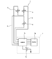
図1の歪みセンサ付き手袋1(以下、単に手袋1ということがある)は、手袋本体3と、この手袋本体3に付設される歪みセンサ5と、この歪みセンサ5の検知信号を送信する送信モジュール7と、歪みセンサ5と送信モジュール7とを電気的に接続する配線部9とを備えている。
<Gloves with strain sensor 1>
1 includes a
(手袋本体3)
手袋本体3は、着用者の手に装着可能な袋状に形成されており、具体的には、開口を有する手首相当部3a、この手首相当部3aから指先側に連設される胴相当部3b(着用者の手首と指との間の五本胴及び四本胴に相当する部分)、及びこの胴相当部3bからそれぞれ指先側に連接される複数の指相当部3cを有している。ここで、指相当部3cは各指に対応して五つ設けられている。より具体的には、指相当部3cとして、親指を収容可能な親指収容部、人差し指を収容可能な人差し指収容部、中指を収容可能な中指収容部、薬指部を収容可能な薬指収容部、及び小指を収容可能な小指収容部が設けられている。
(Glove body 3)
The
手袋本体3は、可撓性を有する布状体が縫製されて形成され、このため手袋本体3は変形可能に設けられている。また、手袋本体3は、着用した際に着用者にフィット感を与えるよう伸縮可能な布状体から構成されている。
The
この手袋本体3の布状体は、一枚の布からなる単層構造であっても良く、また多数の布が積層された多層構造であっても良い。ここで、手袋本体3の布状体を構成する布は、織物、編物、樹脂製又はゴム製シート、不織布等を適宜採用可能である。なか、手袋本体3の布状体は導電性を有さない素材から構成されることが好ましく、手袋本体3は導電性を有さないことが好ましい。
The cloth body of the
(歪みセンサ5)
前記歪みセンサ5は、手袋本体3に複数付設されている。本実施形態においては、手袋本体3の手首相当部3aに付設される歪みセンサ5と、手袋本体3の指相当部3cに付設される歪みセンサ5とを備えている。また、指相当部3cに付設される歪みセンサ5は、薬指収容部に付設される歪みセンサ5と、中指収容部に付設される歪みセンサ5とを備えている。
(Strain sensor 5)
A plurality of the
前記歪みセンサ5は、何れも手袋本体3の掌側の面以外の部位において手袋本体3に付設されている。具体的には、何れの歪みセンサ5も、手袋本体3の手の甲側の面に付設されている。
Each of the
前記歪みセンサ5は、何れも手袋本体3の関節相当部位に付設されている。前記手首相当部3aに付設される歪みセンサ5は、着用者の手関節(撓骨手根関節)が当接する手関節相当部位で前記手袋本体3に付設されている。具体的には、この歪みセンサ5は、手関節相当部位を跨ぐように、手関節相当部位よりも開口側から、手関節相当部位よりも指先側(手根間関節相当部位及び手根中手関節相当部位)に至るまで、手袋本体3に付設されている。
Each of the
また、前記指相当部3cに付設される歪みセンサ5は、近位指節間関節相当部位(指の関節のうち手首に近接する関節に相当する部位)で前記手袋本体3に付設されている。具体的には、薬指収容部に付設される歪みセンサ5は、薬指の近接指節間関節相当部位を跨ぐように、近接指節間関節相当部位よりも手首側から、近接指節間関節相当部位よりも指先側に至るまで、手袋本体3に付設されている。同様に、中指収容部に付設される歪みセンサ5は、中指の近接指節間関節相当部位を跨ぐように、近接指節間関節相当部位よりも手首側から、近接指節間関節相当部位よりも指先側に至るまで、手袋本体3に付設されている。なお、この指相当部3cに付設される歪みセンサ5は、手首側の端部が、中手指節関節相当部まで至らず、中手指節関節相当部と近接指節間関節相当部位との間に位置することが好ましく、また、指先側の端部が、遠位指節間関節相当部まで至らず、遠位指節間関節相当部と近接指節間関節相当部との間に位置することが好ましい。これにより、指相当部3cの歪みセンサ5が、近接指節間関節相当部における指の屈曲をより正確に検知することができる。
Further, the
この歪みセンサ5は、手袋本体3の外面に貼着されており、これにより歪みセンサ13は布帛本体11に一体的に付設されている。なお、歪みセンサ13を手袋本体3に一体的に付設する手段は、貼着に限られず、例えば手袋本体に歪みセンサを縫着したり、また手袋本体に歪みセンサを積層形成することも適宜採用可能である。
The
また、ここで、歪みセンサ5の貼着は、弾性接着剤によってなされていることが好ましい。この弾性接着剤は、硬化後の弾性率が1MPa以上10MPaであることが好ましい。この硬化後の弾性接着剤の弾性率が前記上限を超えると、弾性接着剤が硬化した層によって手袋本体3の変形が阻害され、着用者に違和感を与えるおそれがある。一方、前記弾性率が前記下限未満であると、手袋本体3の変形が弾性接着剤からなる層で吸収されてしまい、歪みセンサ5に的確に伝達されないおそれがある。
Here, it is preferable that the
この歪みセンサ5は、手袋本体3の変形に追従可能に手袋本体3に付設されている。具体的には、歪みセンサ13は伸縮性を有し、伸縮性を有する手袋本体3に一体的に付設されることで、手袋本体3の伸縮に伴って歪みセンサ13が伸縮するよう設けられている。なお、歪みセンサ13を少なくとも両端部分で手袋本体に固定(例えば貼着、縫着等)することで、手袋本体11の変形に従って歪みセンサ13が伸縮するよう設けることも可能である。この歪みセンサ5は、伸縮に応じて電気信号(検知信号)を前記配線部9に送信する。この歪みセンサ5としては、カーボンナノチューブ(以下、CNTということがある)を用いたCNT歪みセンサ5が好適に用いられる。このCNT歪みセンサ5は、前記手袋本体3に貼着される基板と、この基板の表面側に設けられるCNT膜と、このCNT繊維の端部にそれぞれ配設される一対の電極と、前記CNT膜を保護する保護部とを主に備える。
The
前記CNT歪みセンサ5の基板は、柔軟性を有する板状体から構成されている。この基板のサイズとしては特に限定されず、例えば厚みが10μm以上5mm以下、幅が1mm以上5cm以下、長さが1cm以上20cm以下とすることができる。
The substrate of the
この基板の材質としては、柔軟性を有する限り特に限定されず、例えば合成樹脂、ゴム、不織布、変形可能な形状又は材質の金属や金属化合物等を挙げることができる。 The material of the substrate is not particularly limited as long as it has flexibility, and examples thereof include synthetic resin, rubber, non-woven fabric, deformable shape or material metal or metal compound, and the like.
前記合成樹脂としては、例えばフェノール樹脂(PF)、エポキシ樹脂(EP)、メラミン樹脂(MF)、尿素樹脂(ユリア樹脂、UF)、不飽和ポリエステル樹脂(UP)、アルキド樹脂、ポリウレタン(PUR)、熱硬化性ポリイミド(PI)、ポリエチレン(PE)、高密度ポリエチレン(HDPE)、中密度ポリエチレン(MDPE)、低密度ポリエチレン(LDPE)、ポリプロピレン(PP)、ポリ塩化ビニル(PVC)、ポリ塩化ビニリデン、ポリスチレン(PS)、ポリ酢酸ビニル(PVAc)、アクリロニトリルブタジエンスチレン樹脂(ABS)、アクリロニトリルスチレン樹脂(AS)、ポリメチルメタアクリル樹脂(PMMA)、ポリアミド(PA)、ポリアセタール(POM)、ポリカーボネート(PC)、変性ポリフェニレンエーテル(m−PPE)、ポリブチレンテレフタレート(PBT)、ポリエチレンテレフタレート(PET)、環状ポリオレフィン(COP)等を挙げることができる。 Examples of the synthetic resin include phenol resin (PF), epoxy resin (EP), melamine resin (MF), urea resin (urea resin, UF), unsaturated polyester resin (UP), alkyd resin, polyurethane (PUR), Thermosetting polyimide (PI), polyethylene (PE), high density polyethylene (HDPE), medium density polyethylene (MDPE), low density polyethylene (LDPE), polypropylene (PP), polyvinyl chloride (PVC), polyvinylidene chloride, Polystyrene (PS), polyvinyl acetate (PVAc), acrylonitrile butadiene styrene resin (ABS), acrylonitrile styrene resin (AS), polymethyl methacrylate resin (PMMA), polyamide (PA), polyacetal (POM), polycarbonate (PC) , Degeneration Polyphenylene ether (m-PPE), polybutylene terephthalate (PBT), polyethylene terephthalate (PET), and cyclic polyolefin (COP) and the like.
前記ゴムとしては、例えば天然ゴム(NR)、ブチルゴム(IIR)、イソプレンゴム(IR)、エチレン・プロピレンゴム(EPDM)、ブタジエンゴム(BR)、ウレタンゴム(U)、スチレン・ブタジエンゴム(SBR)、シリコーンゴム(Q)、クロロプレンゴム(CR)、クロロスルフォン化ポリエチレンゴム(CSM)、アクリロニトリルブタジエンゴム(NBR)、塩素化ポリエチレン(CM)、アクリルゴム(ACM)、エピクロルヒドリンゴム(CO,ECO)、フッ素ゴム(FKM)、PDMS等を挙げることができる。これらのゴムの中でも強度等の点から天然ゴムが好ましい。 Examples of the rubber include natural rubber (NR), butyl rubber (IIR), isoprene rubber (IR), ethylene / propylene rubber (EPDM), butadiene rubber (BR), urethane rubber (U), and styrene / butadiene rubber (SBR). , Silicone rubber (Q), chloroprene rubber (CR), chlorosulfonated polyethylene rubber (CSM), acrylonitrile butadiene rubber (NBR), chlorinated polyethylene (CM), acrylic rubber (ACM), epichlorohydrin rubber (CO, ECO), Fluoro rubber (FKM), PDMS, etc. can be mentioned. Among these rubbers, natural rubber is preferable from the viewpoint of strength.
電極は、特に限定されるものではないが、導電性弾性接着剤の塗工によって形成されている。なお、この電極は銅等の金属等を用いることも可能であり、金属製の電極にあっては形状がメッシュ状であることが好ましい。 The electrode is not particularly limited, but is formed by applying a conductive elastic adhesive. In addition, it is also possible to use metals, such as copper, for this electrode, and when it is a metal electrode, it is preferable that a shape is a mesh form.
CNT膜は、正面視矩形形状を有している。このCNT膜の長手方向の両端部分に前記電極が接続されている。また、カーボンナノチューブ膜は、一方向(一対の電極を結ぶ直線の方向と異なる方向)に配向する複数のCNT繊維を有している。このようにCNT繊維が配向していることで一対の電極が離れる方向へ歪みが加わった場合(CNT膜が伸長した場合)に、CNT繊維同士の接触具合に変化が起こり、歪みセンサ513として抵抗変化を得ることができる。なお、より効率良く歪みを検出するには、好ましくはCNT膜は一対の電極の配設方向(一対の電極を結ぶ直線の方向)と略垂直方向、好ましくは垂直方向にCNT繊維が配向されていると良い。 The CNT film has a rectangular shape in front view. The electrodes are connected to both ends of the CNT film in the longitudinal direction. Further, the carbon nanotube film has a plurality of CNT fibers oriented in one direction (a direction different from the direction of a straight line connecting a pair of electrodes). Thus, when the CNT fibers are oriented and strain is applied in the direction in which the pair of electrodes are separated (when the CNT film is stretched), the contact condition between the CNT fibers changes, and the strain sensor 513 acts as a resistance. Change can be obtained. In order to detect strain more efficiently, the CNT film preferably has a CNT fiber oriented in a direction substantially perpendicular to the arrangement direction of the pair of electrodes (the direction of a straight line connecting the pair of electrodes), preferably in the perpendicular direction. Good to be.
各CNT繊維は、複数のCNT単繊維から構成することができる。ここで、CNT単繊維とは、1本の長尺のCNTをいう。また、CNT繊維は、CNT単繊維の端部同士が連結する連結部を有する。CNT単繊維同士は、これらのCNT単繊維の長手方向に連結している。このように、CNT膜において、CNT単繊維同士がその長手方向に連結してなるCNT繊維を用いることで、CNT繊維の配向方向に幅の広いCNT膜を形成することができ、その結果、CNT膜の抵抗値を下げ、かつ、この抵抗値のバラツキも低減することができる。 Each CNT fiber can be composed of a plurality of CNT single fibers. Here, the CNT single fiber means one long CNT. In addition, the CNT fiber has a connection portion where the ends of the CNT single fibers are connected to each other. The CNT single fibers are connected in the longitudinal direction of these CNT single fibers. Thus, in the CNT film, by using the CNT fiber formed by connecting the CNT single fibers in the longitudinal direction, a CNT film having a wide width in the alignment direction of the CNT fiber can be formed. The resistance value of the film can be lowered, and variations in the resistance value can also be reduced.
また、複数のCNT繊維は、網目構造を形成している。具体的には、複数のCNT繊維は連結部等により網目状に連結又は接触している。この際、連結部において、3つ以上のCNT単繊維の端部が結合していてもよいし、連結部のように2つのCNT単繊維の端部と他のCNT単繊維の中間部とが結合していてもよい。複数のCNT繊維がこのような網目構造を形成することで、CNT繊維同士が密接し、CNT膜の抵抗を下げることができる。 The plurality of CNT fibers form a network structure. Specifically, the plurality of CNT fibers are connected or in contact with each other by a connecting portion or the like. At this time, at the connecting portion, the ends of three or more CNT single fibers may be combined, or the ends of two CNT single fibers and an intermediate portion of another CNT single fiber as in the connecting portion. It may be bonded. When a plurality of CNT fibers form such a network structure, the CNT fibers are in close contact with each other, and the resistance of the CNT film can be reduced.
また、この際、前記連結部が主な基点なって近隣のCNT繊維同士が連結又は接触することによって、CNT繊維が両持ち梁構造として機能することができる。CNT繊維同士の連結とは前記連結部等とCNT繊維が電気的に繋がることであり、CNT繊維の連結部ではない部分同士が電気的に繋がった場合も連結に含まれる。CNT繊維同士の接触とは前記連結部等とCNT繊維が触れているが電気的に繋がっていないことであり、CNT繊維の連結部ではない部分同士が触れているが電気的に繋がっていない場合も接触に含まれる。両持ち梁として機能するCNT繊維はバネ定数が大きくなる。そのため、CNT繊維は、この配向方向と垂直方向(CNT膜の長手方向)には伸縮しにくい構造となっている。従って、CNT膜がCNT繊維の配向方向と垂直方向(CNT膜の長手方向)に対して剛性が強くなり、そのCNT歪みセンサ5によれば、CNT膜の長手方向の歪みに対して、敏感に検知することができ、さらにリニアリティを高めることができる。なお、CNT繊維の連結部が主な基点となって、隣り合うCNT繊維間に限らず、何本か飛び越えた場所のCNT繊維と連結又は接触してもよい。このように、複雑な網目状のCNT繊維を有するCNT膜であれば、より抵抗値が低くなり、CNT繊維と垂直な方向に剛性の強い歪みセンサ5とすることができる。
At this time, the CNT fibers can function as a doubly supported beam structure by connecting or contacting neighboring CNT fibers with the connecting portion as a main base point. The connection between the CNT fibers means that the connection portion and the CNT fibers are electrically connected to each other, and the case where the portions other than the connection portion of the CNT fibers are electrically connected is also included in the connection. The contact between the CNT fibers means that the CNT fibers and the CNT fibers are in contact with each other but are not electrically connected to each other, and the portions that are not the CNT fiber connection parts are in contact with each other but are not electrically connected to each other. Is also included in the contact. A CNT fiber that functions as a doubly supported beam has a large spring constant. Therefore, the CNT fiber has a structure that hardly stretches in the direction perpendicular to the orientation direction (longitudinal direction of the CNT film). Therefore, the rigidity of the CNT film becomes stronger in the direction perpendicular to the orientation direction of the CNT fibers (longitudinal direction of the CNT film), and the
なお、CNT繊維は、各CNT単繊維が実質的にCNT繊維の長手方向に配向され、撚糸されていない状態のものである。このようなCNT繊維を用いることで、CNT膜の均一性を高め、歪みセンサ5としてのリニアリティを高めることができる。
The CNT fiber is in a state where each CNT single fiber is substantially oriented in the longitudinal direction of the CNT fiber and is not twisted. By using such a CNT fiber, the uniformity of the CNT film can be enhanced and the linearity as the
なお、前記連結部において、各CNT単繊維同士は分子間力により結合している。このため、複数のCNT繊維が連結部により網目状に連結した場合においても、連結部の存在による抵抗の上昇が抑えられる。 In addition, in the said connection part, each CNT single fiber is couple | bonded by the intermolecular force. For this reason, even when a plurality of CNT fibers are connected in a mesh shape by the connecting portion, an increase in resistance due to the presence of the connecting portion is suppressed.
CNT膜のサイズについては特に限定されるものではないが、例えばCNT膜の幅(短手方向の長さ)は、好ましくは1mm以上10cm以下、より好ましくは1cm以上5cm以下の範囲内とすることができる。CNT膜の幅を比較的大きくすることで、CNT膜の抵抗値を下げ、かつ、この抵抗値のバラツキも低減することができる。 The size of the CNT film is not particularly limited. For example, the width (length in the short direction) of the CNT film is preferably in the range of 1 mm to 10 cm, more preferably 1 cm to 5 cm. Can do. By making the width of the CNT film relatively large, the resistance value of the CNT film can be lowered, and variations in the resistance value can also be reduced.
CNT膜の厚みとしては、特に限定されないが、例えば、CNT膜の平均厚みの下限としては、1μmが好ましく、10μmがさらに好ましい。一方、CNT膜の平均厚みの上限としては、5mmが好ましく、1mmがさらに好ましい。CNT膜の平均厚みが前記下限未満の場合は、このような薄膜の形成が困難になるおそれや、抵抗が上昇しすぎるおそれがある。逆に、CNT膜の平均厚みが前記上限を超える場合は、伸縮性が低下するおそれがあるとともに伸縮に対する感受性が低下するおそれがあり、さらには着用者に違和感を与えるおそれがある。 Although it does not specifically limit as thickness of a CNT film | membrane, For example, as a minimum of the average thickness of a CNT film | membrane, 1 micrometer is preferable and 10 micrometers is more preferable. On the other hand, the upper limit of the average thickness of the CNT film is preferably 5 mm, and more preferably 1 mm. If the average thickness of the CNT film is less than the lower limit, it may be difficult to form such a thin film, or the resistance may increase excessively. On the contrary, when the average thickness of the CNT film exceeds the upper limit, the stretchability may be lowered, the sensitivity to the stretch may be lowered, and the wearer may be uncomfortable.
なお、CNT膜は、CNT繊維を平面状に略平行に配置した単層構造からなってもよいし、多層構造からなってもよい。但し、ある程度の導電性を確保するためには、多層構造とすることが好ましい。 Note that the CNT film may have a single-layer structure in which CNT fibers are arranged substantially in parallel in a planar shape, or may have a multilayer structure. However, in order to ensure a certain degree of conductivity, a multilayer structure is preferable.
CNT繊維としては、単層のシングルウォールナノチューブ(SWNT)や、多層のマルチウォールナノチューブ(MWNT)のいずれも用いることができるが、導電性及び熱容量等の点から、MWNTが好ましく、直径1.5nm以上100nm以下のMWNTがさらに好ましい。 As the CNT fiber, either single-walled single-wall nanotubes (SWNT) or multi-walled multi-wall nanotubes (MWNT) can be used, but MWNT is preferable from the viewpoint of conductivity and heat capacity, and the diameter is 1.5 nm. More preferably, the MWNT is 100 nm or less.
(送信モジュール7)
前記送信モジュール7は、手袋本体3に付設されている。この送信モジュール7は、着用者の邪魔にならない箇所に配設され、例えば手の甲側において手の胴に相当する部位に付設されている。
(Transmission module 7)
The
また、この送信モジュール7は、手袋本体3に着脱可能に付設されている。なお、この着脱可能に付設する手段は特に限定されないが、例えば面ファスナー等を採用可能である。前記のように送信モジュール7を手袋本体3に着脱可能に設けることで、送信モジュール7を取り外した状態で手袋本体3を容易且つ確実に洗濯することが可能となる。
The
送信モジュール7は、電源7a(電池)、送信手段7b及び処理手段7cを有している。この送信手段7bは、配線部9を介して受け取った検知信号を、外部機器に無線通信によって送信する。また、処理手段7cは、配線部9を介して受け取った検知信号の判別を行い、この判別を行った後の検知信号を送信手段7bによって送信させる処理を行う。なお、当該歪みセンサ付き手袋1が、配線部9を介して受け取った検知信号を蓄積する記憶手段を有する構成を採用することも可能である。
The
(配線部9)
前記配線部9は、複数の歪みセンサ5と、前記送信モジュール7とを電気的に接続するために複数対有している。本実施形態においては、図2に示すように、送信モジュール7と、指相当部3cの二つの歪みセンサ5とを直列的に接続する一対の配線部9を有しており、また送信モジュール7と、手首相当部3aの一つの歪みセンサ5とを接続する一対の配線部9を有している。なお、複数の歪みセンサ5と送信モジュール7との電気的接続は上記接続に限定されるものではなく、全ての歪みセンサ5を並列で接続することも、全ての歪みセンサ5を直列で接続することも適宜設計変更可能な事項である。
(Wiring part 9)
The
前記配線部9は手袋本体3に付設されており、配線部9は手袋本体3に一体的に付設されている。具体的には、配線部9は、手袋本体3に縫い付けられた導電性を有する糸(糸状体)から構成されている。
The
この配線部9を構成する糸は、導電性を有する導電糸が用いられる。この導電糸としては、鉄等の金属製の導電糸を用いることができ、この金属製の導電糸としてはステンレス糸が好適に用いられる。ステンレス糸によれば、電気抵抗が小さく、また当該手袋本体3を洗濯した場合にあっても電気抵抗の変化が比較的少ない利点を有する。なお、この配線部9を構成する糸としては、絶縁性の糸に導電性材料を塗工した糸や、導電性材料を混紡して形成した糸を用いることも可能である。
As the yarn constituting the
この配線部9を構成する糸は、10cmあたりの電気抵抗が100Ω未満であることが好ましく、50Ω未満であることがさらに好ましい。これにより、配線部9の電気抵抗を小さくすることができ、歪みセンサ5からの検知信号を的確に送信モジュール7に伝達することができる。なお、「10cmあたりの抵抗値」とは、5Vの電圧をかけたときの糸10cm間の抵抗値であり、汎用のテスターを用いて測定することができる。
The yarn constituting the
配線部9は、伸縮性を有し、手袋本体3の変形に追従して変形するよう設けられている。具体的には、配線部9は、導電性を有する糸を伸縮縫いすることによって形成されている。なお、伸縮縫いとは、「JIS B 9003」で規定されるように、「伸縮性のある布地を縫ったとき、布地の伸び縮みによって、縫い目が切れたり、緩んだりしないように縫うこと」を意味する。具体的には、本実施形態の配線部9は、カバーステッチ(片面飾り縫い)等によって形成可能である。
The
<利点>
前記構成からなるセンサ付き手袋1にあっては、着用者の動作によって手袋本体3が変形し歪みセンサ5が伸縮されると、歪みセンサ5が配線部9を介して検知信号を送信モジュール7に送信し、この検知信号を受け取った送信モジュール7は外部機器に検知信号を送信する。このため、外部機器において、検知信号を判別することによって、着用者の手の動きを検知することできる。
<Advantages>
In the glove with a sensor 1 having the above-described configuration, when the
特に、当該センサ付き手袋1にあっては、従来の手袋1のように圧縮式センサではなく伸縮による検知信号を用いるため、圧縮の場合に比して的確且つ正確に手の動きをセンシングすることができる。また、歪みセンサ5は弾性接着剤によって手袋本体3に貼着されているので、着用者の動作によって手袋本体3が的確に変形し、歪みセンサ5が的確に伸縮することができる。
In particular, the sensor-equipped glove 1 uses a detection signal based on expansion and contraction instead of a compression sensor as in the conventional glove 1, and therefore senses the movement of the hand more accurately and accurately than in the case of compression. Can do. In addition, since the
また、当該歪みセンサ付き手袋1の歪みセンサ5は、手袋本体3の掌側以外の部位に付設され、ゴルフクラブ(把持物)と手との間に位置しないので、着用者の違和感を与えにくく、このため普段のゴルフスイングを行うことができ、普段のゴルフスイングにおける手の動きを正確に把握することができる。
Further, the
特に歪みセンサ5としてCNT膜を有するCNTセンサを用いているので、他の歪みセンサ5に比べて薄型化が図られるとともに感度及び応答性が高く、着用者の違和感をより少なくすることができるとともに的確且つ正確に手の動きを把握することができる。
In particular, since a CNT sensor having a CNT film is used as the
また、前記歪みセンサ5が関節相当部位に付設されているので、この関節における手の動きを的確に把握することができる。特に、歪みセンサ5は手関節相当部位に付設されていれば、着用者の手首の動きを正確に検知することができる。特にゴルフスイング中における手首の動きを正確に把握することができるため、着用者の手首のコックがどの程度なされているかを容易且つ確実に認識することが可能となる。
Further, since the
さらに、前記歪みセンサ5が指相当部3cの近接指節間関節相当部位に付設されていれば、被把持物を把持する際の指関節の使い方を容易且つ確実に判断することができる。特にゴルフスイング中において指の動きを正確に把握することができるので、打球時、着用者が構えてからインパクトの瞬間にゴルフクラブをどのように把持しているかを容易且つ確実に認識することができる。上記実施形態においては、薬指収容部及び中指収容部に歪みセンサ5を付設しているので、ゴルフクラブを把持する際に重要な指の動きを正確に把握することができ、より確実にゴルフクラブの把持状態を把握することができる。
Furthermore, if the
また、前記配線部9は手袋本体3に一体的に取付けられているので、着用者の動作の邪魔になりにくい。また、配線部9は伸縮性を有し、手袋本体3の変形に追従して変形するので、配線部9が手袋本体3の伸縮を妨げにくく、着用者に違和感を与えにくく、また着用者の動作の邪魔になりにくい。また、配線部9が伸縮性を有するので、当該歪みセンサ付き手袋1の着脱を困難ならしめることがない。
Moreover, since the said
<その他の実施形態>
本実施形態は前記構成からなり、上述の利点を奏するものであったが、本発明は前記実施形態に限定されるものではなく、本発明の意図する範囲内において適宜設計変更可能である。
<Other embodiments>
Although the present embodiment has the above-described configuration and has the above-described advantages, the present invention is not limited to the above-described embodiment, and the design can be changed as appropriate within the intended scope of the present invention.
前記実施形態においては、手袋本体3の指相当部3cに二つの歪みセンサ5を付設し、手首相当部3aに一つの歪みセンサ5を付設し、つまり手袋本体3全体として三つの歪みセンサ5を付設したものについて説明したが、本発明はこれに限定されるものではなく、例えば手袋本体に一つの歪みセンサが付設されているものであれば本発明の意図する範囲内である。
In the embodiment, two
また、歪みセンサ5の付設箇所も上記実施形態のものに限定されるものではない。しかしながら、上記実施形態のように手関節相当部位に前記歪みセンサ5を付設することによって、手首の動きを的確に把握することができ、特にスポーツ等に際して重要な手の動きを測定することができる。また、上記実施形態のように指の近接指節間関節相当部位(特に薬指の近接指節間関節相当部位及び/又は中指の近接指節間関節相当部位)に前記歪みセンサ5を付設することによって、把持物の把持状態を的確に把握することができ、特にゴルフ、野球等の、把持する用具により打球するスポーツ用手袋として好適である。
Further, the attachment location of the
さらに、上記実施形態においては、歪みセンサ5を手袋本体3の外面に付設するものについて説明したが、本発明はこれに限定されるものではなく、歪みセンサを手袋本体の内面(着用者の手に当接する面)に付設したり、さらには手袋本体が多層構造である場合には歪みセンサを手袋本体に内蔵(多層構造の中間層に介在)させることも可能である。なお、歪みセンサは、手袋本体の内面以外の部位(例えば手袋本体の外面)に付設されていることが好ましく、これにより着用者に違和感を与えにくいという利点を有する。
Furthermore, in the said embodiment, although what attached the
また、前記実施形態は、歪みセンサ5の付設方法として弾性接着剤を用いたものについて説明したが、本発明はこれに限定されるものではなく、その他の付設方法も適宜採用可能である。例えば歪みセンサをその伸縮性を損なわないように縫い付けることで手袋本体に付設することも可能である。また、歪みセンサと手袋本体とを面ファスナー等によって貼着することで、手袋本体に着脱可能に歪みセンサを付設することも可能である。
Moreover, although the said embodiment demonstrated what used the elastic adhesive as an attachment method of the
また、上記実施形態においては配線部9が手袋本体3に一体的に設けられているものについて説明したが、本発明は必ずしもこれに限定されるものではない。また、伸縮性を有する配線部9を手袋本体3に一体的に設ける場合にあっても、配線部9の形成方法は前記伸縮縫いに限定されるものではない。例えば、配線部として、手袋本体を構成する布状体の編成又は織成に際して導電性を有さない糸状体とともに導電性を有する糸状体を編成又は織成することで、この導電性を有する糸状体から構成される配線部を採用可能である。具体的には、布状体をニット編みによって編成し、このニット編みの一つ又は複数のコースを導電性を有する糸で編成することで、この導電性を有する糸で編成されたコースの部分によって配線部を形成することが可能である。
Moreover, in the said embodiment, although the
また、配線部9として、手袋本体3の一方の面に付設された導電性を有する帯状部材から構成することも可能である。具体的には、例えば導電性を有する糸を編成して伸縮性及び導電性を有する紐(帯状部材)を形成し、この帯状部材を手袋本体に付設することも可能である。なお、この付設方法としては、弾性接着剤による貼着や、伸縮性を損なわないように縫い付ける等の方法を採用することができる。
In addition, the
また、配線部9を前記実施形態のように導電性を有する糸を縫い付けて形成する場合にあっても、前記のような伸縮編みによって形成するものに限定されるものではない。具体的には、例えば手袋本体に導電性及び伸縮性を有する糸をロックステッチによって縫いつけて、この糸によって伸縮性を有する配線部を形成することも可能である。
Further, even when the
さらに、前記実施形態のように伸縮編みによって配線部9を形成する場合にあっても、カバーステッチによって形成するものに限定されるものではなく、その他の縫い方によって配線部を形成することも可能である。具体的には、チェーンステッチによって手袋本体に糸を縫い付けることで配線部を形成することも可能である。
Further, even when the
なお、当該歪みセンサ付き手袋1にあっては、前記配線部9は、一つの種類のみを採用するものに限られず、上述において説明した複数種類の配線部を組み合わせて用いることも適宜設計変更可能な事項である。
In addition, in the glove 1 with a strain sensor, the
また、前記実施形態においては、センサ付き手袋1としてゴルフグローブを例にとり説明したが、本発明はこれに限定されるものではなく、例えばその他のスポーツウェアを採用することも可能である。さらには、当該センサ付き手袋としてオートバイや車を運転する際に装着されるドライブ用手袋を採用することも可能である。このようにドライブ用手袋に本願発明を適用した場合、当該ドライブ用手袋が装着者の挙動異常(例えば睡眠等による挙動異常)を認識した際に、外部機器に注意信号を発振させるような構成を採用することもできる。 In the above embodiment, a golf glove has been described as an example of the sensor-equipped glove 1. However, the present invention is not limited to this, and other sportswear may be employed, for example. Furthermore, it is also possible to employ a drive glove that is worn when driving a motorcycle or a car as the sensor-equipped glove. In this way, when the present invention is applied to a drive glove, when the drive glove recognizes a wearer's behavior abnormality (for example, a behavior abnormality due to sleep or the like), a configuration that oscillates a caution signal to an external device is configured. It can also be adopted.
以上説明したように、本発明の歪みセンサ付き手袋は、着用者に違和感を与えにくく、着用者の手の動きを正確に捉えやすいので、例えばゴルフグローブ等のスポーツ用手袋に好適に用いることができる。 As described above, the glove with a strain sensor of the present invention is suitable for sports gloves such as a golf glove because it does not give the wearer a sense of incongruity and easily captures the movement of the wearer's hand. it can.
1 歪みセンサ付き手袋
3 手袋本体
3a 手首相当部
3b 胴相当部
3c 指相当部
5 歪みセンサ
7 送信モジュール
7a 電源
7b 送信手段
7c 処理手段
9 配線部
DESCRIPTION OF SYMBOLS 1 Glove with a
Claims (4)
この手袋本体に付設され、手袋本体の変形に追従して伸縮するシート状の1又は複数の歪みセンサと
を備える歪みセンサ付手袋。 A glove body that can be worn on the wearer's hand;
A glove with a strain sensor, comprising: one or a plurality of sheet-shaped strain sensors attached to the glove body and extending and contracting following the deformation of the glove body.
The glove with a strain sensor according to claim 1, wherein the strain sensor is attached to a portion other than the palm-side surface of the glove body and a joint-corresponding portion.
Priority Applications (2)
| Application Number | Priority Date | Filing Date | Title |
|---|---|---|---|
| JP2012167735A JP2014025179A (en) | 2012-07-27 | 2012-07-27 | Glove with strain sensor |
| JP2016251807A JP6341268B2 (en) | 2012-07-27 | 2016-12-26 | Gloves with strain sensor |
Applications Claiming Priority (1)
| Application Number | Priority Date | Filing Date | Title |
|---|---|---|---|
| JP2012167735A JP2014025179A (en) | 2012-07-27 | 2012-07-27 | Glove with strain sensor |
Related Child Applications (1)
| Application Number | Title | Priority Date | Filing Date |
|---|---|---|---|
| JP2016251807A Division JP6341268B2 (en) | 2012-07-27 | 2016-12-26 | Gloves with strain sensor |
Publications (2)
| Publication Number | Publication Date |
|---|---|
| JP2014025179A true JP2014025179A (en) | 2014-02-06 |
| JP2014025179A5 JP2014025179A5 (en) | 2015-11-26 |
Family
ID=50199074
Family Applications (2)
| Application Number | Title | Priority Date | Filing Date |
|---|---|---|---|
| JP2012167735A Pending JP2014025179A (en) | 2012-07-27 | 2012-07-27 | Glove with strain sensor |
| JP2016251807A Active JP6341268B2 (en) | 2012-07-27 | 2016-12-26 | Gloves with strain sensor |
Family Applications After (1)
| Application Number | Title | Priority Date | Filing Date |
|---|---|---|---|
| JP2016251807A Active JP6341268B2 (en) | 2012-07-27 | 2016-12-26 | Gloves with strain sensor |
Country Status (1)
| Country | Link |
|---|---|
| JP (2) | JP2014025179A (en) |
Cited By (5)
| Publication number | Priority date | Publication date | Assignee | Title |
|---|---|---|---|---|
| JP2016069761A (en) * | 2014-09-30 | 2016-05-09 | 国立大学法人大阪大学 | Rubber glove with electrode and manufacturing method thereof, and hand mold for manufacturing rubber glove with electrode |
| JP2018115884A (en) * | 2017-01-16 | 2018-07-26 | ヤマハ株式会社 | Sensor unit |
| CN112434592A (en) * | 2020-11-19 | 2021-03-02 | 维沃移动通信有限公司 | Wearing detection method, glove and readable storage medium |
| WO2022220032A1 (en) * | 2021-04-12 | 2022-10-20 | パナソニックIpマネジメント株式会社 | Wearable sensing device |
| WO2022220034A1 (en) * | 2021-04-12 | 2022-10-20 | パナソニックIpマネジメント株式会社 | Wearable sensing device |
Families Citing this family (4)
| Publication number | Priority date | Publication date | Assignee | Title |
|---|---|---|---|---|
| CN115176219A (en) | 2020-03-24 | 2022-10-11 | 琳得科株式会社 | Motion detection system |
| CN115315678A (en) | 2020-03-24 | 2022-11-08 | 琳得科株式会社 | Component for detecting motion |
| KR102346902B1 (en) * | 2020-09-03 | 2022-01-04 | 박우람 | Golf glove for posture correction |
| JP7216758B2 (en) * | 2021-03-19 | 2023-02-01 | 本田技研工業株式会社 | Program and information generation method |
Citations (8)
| Publication number | Priority date | Publication date | Assignee | Title |
|---|---|---|---|---|
| JPS63307610A (en) * | 1987-06-08 | 1988-12-15 | Horikawa Densen Kk | Electrical wire |
| JPH05285249A (en) * | 1992-04-10 | 1993-11-02 | Sanyo Kogyo Kk | Wristwork detecting device and glove provided with wristwork detecting device |
| JPH0637318U (en) * | 1992-10-19 | 1994-05-17 | 株式会社吉本商店 | Work gloves with fingertip rubber cap |
| JP3095738U (en) * | 2003-02-05 | 2003-08-15 | 公二 照沼 | Golf gloves |
| JP2005226217A (en) * | 2004-02-10 | 2005-08-25 | Adidas Internatl Marketing Bv | Wear |
| WO2008078780A1 (en) * | 2006-12-26 | 2008-07-03 | Asahi Kasei Fibers Corporation | Expandable electric wire and its manufacturing method |
| US20080189827A1 (en) * | 2005-04-20 | 2008-08-14 | David Bauer | Golf Training Glove |
| JP2011047702A (en) * | 2009-08-25 | 2011-03-10 | National Institute Of Advanced Industrial Science & Technology | Expansion device using carbon nanotube and method of manufacturing the same |
Family Cites Families (9)
| Publication number | Priority date | Publication date | Assignee | Title |
|---|---|---|---|---|
| JPS5838769B2 (en) * | 1975-12-24 | 1983-08-25 | セイコーエプソン株式会社 | exiyouhiyoujisouchi |
| JP2538903B2 (en) * | 1987-02-27 | 1996-10-02 | ヤマハ株式会社 | Music control device |
| JPH10286338A (en) * | 1997-04-11 | 1998-10-27 | C Cozza Frank | Golf exercise tool of glove for electronic golf |
| JP4057877B2 (en) * | 2002-10-15 | 2008-03-05 | 旭化成テクノプラス株式会社 | Telescopic wire |
| JP4753305B2 (en) * | 2006-03-29 | 2011-08-24 | 本田技研工業株式会社 | Electric wire built-in belt |
| JP5219829B2 (en) * | 2006-11-14 | 2013-06-26 | 株式会社ブリヂストン | Tire with sensor |
| JP5432513B2 (en) * | 2008-12-18 | 2014-03-05 | 旭化成せんい株式会社 | Biological signal measuring device |
| JP2011065473A (en) * | 2009-09-17 | 2011-03-31 | Toshiba Corp | Portable electronic device |
| US8572764B2 (en) * | 2010-12-09 | 2013-11-05 | Dieter Thellmann | Exercising glove |
-
2012
- 2012-07-27 JP JP2012167735A patent/JP2014025179A/en active Pending
-
2016
- 2016-12-26 JP JP2016251807A patent/JP6341268B2/en active Active
Patent Citations (8)
| Publication number | Priority date | Publication date | Assignee | Title |
|---|---|---|---|---|
| JPS63307610A (en) * | 1987-06-08 | 1988-12-15 | Horikawa Densen Kk | Electrical wire |
| JPH05285249A (en) * | 1992-04-10 | 1993-11-02 | Sanyo Kogyo Kk | Wristwork detecting device and glove provided with wristwork detecting device |
| JPH0637318U (en) * | 1992-10-19 | 1994-05-17 | 株式会社吉本商店 | Work gloves with fingertip rubber cap |
| JP3095738U (en) * | 2003-02-05 | 2003-08-15 | 公二 照沼 | Golf gloves |
| JP2005226217A (en) * | 2004-02-10 | 2005-08-25 | Adidas Internatl Marketing Bv | Wear |
| US20080189827A1 (en) * | 2005-04-20 | 2008-08-14 | David Bauer | Golf Training Glove |
| WO2008078780A1 (en) * | 2006-12-26 | 2008-07-03 | Asahi Kasei Fibers Corporation | Expandable electric wire and its manufacturing method |
| JP2011047702A (en) * | 2009-08-25 | 2011-03-10 | National Institute Of Advanced Industrial Science & Technology | Expansion device using carbon nanotube and method of manufacturing the same |
Cited By (5)
| Publication number | Priority date | Publication date | Assignee | Title |
|---|---|---|---|---|
| JP2016069761A (en) * | 2014-09-30 | 2016-05-09 | 国立大学法人大阪大学 | Rubber glove with electrode and manufacturing method thereof, and hand mold for manufacturing rubber glove with electrode |
| JP2018115884A (en) * | 2017-01-16 | 2018-07-26 | ヤマハ株式会社 | Sensor unit |
| CN112434592A (en) * | 2020-11-19 | 2021-03-02 | 维沃移动通信有限公司 | Wearing detection method, glove and readable storage medium |
| WO2022220032A1 (en) * | 2021-04-12 | 2022-10-20 | パナソニックIpマネジメント株式会社 | Wearable sensing device |
| WO2022220034A1 (en) * | 2021-04-12 | 2022-10-20 | パナソニックIpマネジメント株式会社 | Wearable sensing device |
Also Published As
| Publication number | Publication date |
|---|---|
| JP6341268B2 (en) | 2018-06-13 |
| JP2017061770A (en) | 2017-03-30 |
Similar Documents
| Publication | Publication Date | Title |
|---|---|---|
| JP6341268B2 (en) | Gloves with strain sensor | |
| CN107077207B (en) | Data glove | |
| JP6019890B2 (en) | Fabric and clothing with strain sensor | |
| JP6524663B2 (en) | Data glove | |
| Liu et al. | Functionalized fiber-based strain sensors: pathway to next-generation wearable electronics | |
| JP6759689B2 (en) | Distortion sensor unit | |
| JP6264825B2 (en) | Fabric and clothing with strain sensor | |
| JP6701748B2 (en) | Strain sensor element | |
| JP2017075847A (en) | Movement detection device | |
| US11071498B2 (en) | Smart clothing with inertial, strain, and electromyographic sensors for human motion capture | |
| JP2016125931A (en) | Data glove | |
| US20200330002A1 (en) | Piezoelectric patch sensor | |
| JP2017110307A (en) | Clothing | |
| WO2021192737A1 (en) | Motion detection system | |
| WO2016060031A1 (en) | Data glove | |
| JP2016127898A (en) | Leg exercise detection supporter and supporter for mounting leg exercise detection sensor | |
| JP6687131B2 (en) | Tactile sensor | |
| JP6848458B2 (en) | Sensor unit | |
| JP2018096797A (en) | Extensible structure, manufacturing method of extensible structure, and sensor component | |
| WO2021192748A1 (en) | Motion-detecting member | |
| US11304628B2 (en) | Smart clothing with dual inertial sensors and dual stretch sensors for human motion capture | |
| JP2018021270A (en) | Human body motion detecting wear | |
| JP2017164296A (en) | Action detection device | |
| WO2018012142A1 (en) | Biosignal detector | |
| JP2017211215A (en) | Strain sensor unit and strain measurement kit |
Legal Events
| Date | Code | Title | Description |
|---|---|---|---|
| A621 | Written request for application examination |
Free format text: JAPANESE INTERMEDIATE CODE: A621 Effective date: 20150520 |
|
| A521 | Request for written amendment filed |
Free format text: JAPANESE INTERMEDIATE CODE: A523 Effective date: 20151007 |
|
| A977 | Report on retrieval |
Free format text: JAPANESE INTERMEDIATE CODE: A971007 Effective date: 20160318 |
|
| A131 | Notification of reasons for refusal |
Free format text: JAPANESE INTERMEDIATE CODE: A131 Effective date: 20160329 |
|
| A521 | Request for written amendment filed |
Free format text: JAPANESE INTERMEDIATE CODE: A523 Effective date: 20160526 |
|
| A131 | Notification of reasons for refusal |
Free format text: JAPANESE INTERMEDIATE CODE: A131 Effective date: 20161025 |
|
| A521 | Request for written amendment filed |
Free format text: JAPANESE INTERMEDIATE CODE: A523 Effective date: 20161222 |
|
| A02 | Decision of refusal |
Free format text: JAPANESE INTERMEDIATE CODE: A02 Effective date: 20170606 |