JP6759689B2 - Distortion sensor unit - Google Patents
Distortion sensor unit Download PDFInfo
- Publication number
- JP6759689B2 JP6759689B2 JP2016094481A JP2016094481A JP6759689B2 JP 6759689 B2 JP6759689 B2 JP 6759689B2 JP 2016094481 A JP2016094481 A JP 2016094481A JP 2016094481 A JP2016094481 A JP 2016094481A JP 6759689 B2 JP6759689 B2 JP 6759689B2
- Authority
- JP
- Japan
- Prior art keywords
- strain sensor
- base material
- strain
- sensor unit
- longitudinal direction
- Prior art date
- Legal status (The legal status is an assumption and is not a legal conclusion. Google has not performed a legal analysis and makes no representation as to the accuracy of the status listed.)
- Active
Links
Images


Classifications
-
- G—PHYSICS
- G01—MEASURING; TESTING
- G01B—MEASURING LENGTH, THICKNESS OR SIMILAR LINEAR DIMENSIONS; MEASURING ANGLES; MEASURING AREAS; MEASURING IRREGULARITIES OF SURFACES OR CONTOURS
- G01B7/00—Measuring arrangements characterised by the use of electric or magnetic techniques
- G01B7/16—Measuring arrangements characterised by the use of electric or magnetic techniques for measuring the deformation in a solid, e.g. by resistance strain gauge
- G01B7/18—Measuring arrangements characterised by the use of electric or magnetic techniques for measuring the deformation in a solid, e.g. by resistance strain gauge using change in resistance
-
- G—PHYSICS
- G01—MEASURING; TESTING
- G01L—MEASURING FORCE, STRESS, TORQUE, WORK, MECHANICAL POWER, MECHANICAL EFFICIENCY, OR FLUID PRESSURE
- G01L1/00—Measuring force or stress, in general
- G01L1/20—Measuring force or stress, in general by measuring variations in ohmic resistance of solid materials or of electrically-conductive fluids; by making use of electrokinetic cells, i.e. liquid-containing cells wherein an electrical potential is produced or varied upon the application of stress
- G01L1/22—Measuring force or stress, in general by measuring variations in ohmic resistance of solid materials or of electrically-conductive fluids; by making use of electrokinetic cells, i.e. liquid-containing cells wherein an electrical potential is produced or varied upon the application of stress using resistance strain gauges
- G01L1/2206—Special supports with preselected places to mount the resistance strain gauges; Mounting of supports
-
- G—PHYSICS
- G01—MEASURING; TESTING
- G01L—MEASURING FORCE, STRESS, TORQUE, WORK, MECHANICAL POWER, MECHANICAL EFFICIENCY, OR FLUID PRESSURE
- G01L1/00—Measuring force or stress, in general
- G01L1/20—Measuring force or stress, in general by measuring variations in ohmic resistance of solid materials or of electrically-conductive fluids; by making use of electrokinetic cells, i.e. liquid-containing cells wherein an electrical potential is produced or varied upon the application of stress
- G01L1/22—Measuring force or stress, in general by measuring variations in ohmic resistance of solid materials or of electrically-conductive fluids; by making use of electrokinetic cells, i.e. liquid-containing cells wherein an electrical potential is produced or varied upon the application of stress using resistance strain gauges
- G01L1/2268—Arrangements for correcting or for compensating unwanted effects
Landscapes
- Physics & Mathematics (AREA)
- General Physics & Mathematics (AREA)
- Measurement Of Length, Angles, Or The Like Using Electric Or Magnetic Means (AREA)
Description
本発明は、歪みセンサユニットに関する。 The present invention relates to a strain sensor unit.
伸縮に対する抵抗体の抵抗変化から歪みを検出する歪みセンサユニットが知られている。また、このような抵抗体としては、一般的には金属や半導体が用いられている。しかしながら、金属や半導体は可逆的に伸縮可能な変形量が小さい。そのため、抵抗体として金属や半導体を用いた歪みセンサユニットは用途等に制限がある。 A strain sensor unit that detects strain from changes in the resistance of a resistor to expansion and contraction is known. Further, as such a resistor, a metal or a semiconductor is generally used. However, metals and semiconductors have a small amount of deformation that can be reversibly expanded and contracted. Therefore, the strain sensor unit using a metal or a semiconductor as a resistor has limited applications.
そこで、前記抵抗体として、カーボンナノチューブ(CNT)を用いた歪みセンサユニットが提案されている(特開2011−47702号公報参照)。この公報に記載の歪みセンサユニットは、所定方向に配向させた複数のカーボンナノチューブを含むカーボンナノチューブ膜を有する。具体的には、前記歪みセンサユニットは、帯状のカーボンナノチューブ膜の両端部を測定対象に固定することで、カーボンナノチューブ膜の伸縮歪みを検出する。この歪みセンサは、カーボンナノチューブ膜がカーボンナノチューブの配向方向又は配向方向と垂直方向へ比較的大きく伸縮できるため、大きな歪みにも対応できる。 Therefore, a strain sensor unit using carbon nanotubes (CNT) has been proposed as the resistor (see Japanese Patent Application Laid-Open No. 2011-47702). The strain sensor unit described in this publication has a carbon nanotube film containing a plurality of carbon nanotubes oriented in a predetermined direction. Specifically, the strain sensor unit detects the expansion and contraction strain of the carbon nanotube film by fixing both ends of the strip-shaped carbon nanotube film to the measurement target. Since the carbon nanotube film can expand and contract relatively large in the orientation direction of the carbon nanotubes or in the direction perpendicular to the orientation direction, this strain sensor can cope with a large strain.
前記公報には、前記歪みセンサユニットを手袋に配設して手の指の動きを検出することも提案している。このように、カーボンナノチューブ膜を用いる歪みセンサユニットを人体の表面に装着される布帛に配設する場合、布帛が人体表面上で滑ることによって、歪みセンサユニットが位置ずれするおそれがある。測定対象部位によっては、布帛が人体に対して位置ずれしやすい場合や、歪みセンサユニットのわずかな位置ずれによって検出精度が大きく低下する場合がある。 The publication also proposes that the strain sensor unit is arranged on a glove to detect the movement of fingers of a hand. When the strain sensor unit using the carbon nanotube film is arranged on the cloth mounted on the surface of the human body in this way, the strain sensor unit may be displaced due to the cloth slipping on the surface of the human body. Depending on the part to be measured, the fabric may be easily displaced with respect to the human body, or the detection accuracy may be significantly reduced due to a slight displacement of the strain sensor unit.
前記不都合に鑑みて、本発明は、歪みセンサの位置ずれを抑制できる歪みセンサユニットを提供することを課題とする。 In view of the above inconvenience, it is an object of the present invention to provide a strain sensor unit capable of suppressing the displacement of the strain sensor.
前記課題を解決するためになされた発明は、伸縮性を有する基材と、前記基材に積層され、前記基材の伸縮方向に沿って配設される帯状の1又は複数の歪みセンサと、前記1又は複数の歪みセンサの長手方向両端近傍に歪みセンサの長手方向に交差する方向に延びるよう配設され、前記歪みセンサよりも曲げ弾性率が大きい1対の変形抑制部とを備える歪みセンサユニットである。 The invention made to solve the above problems includes a stretchable base material, a strip-shaped one or a plurality of strain sensors laminated on the base material and arranged along the stretch direction of the base material. A strain sensor including a pair of deformation suppressing portions which are arranged near both ends of the strain sensor in the longitudinal direction so as to extend in a direction intersecting the longitudinal direction of the strain sensor and have a flexural modulus larger than that of the strain sensor. It is a unit.
当該歪みセンサユニットは、前記1又は複数の歪みセンサの長手方向両端近傍に歪みセンサの長手方向に交差する方向に延びるよう配設され、前記歪みセンサよりも曲げ弾性率が大きい1対の変形抑制部を備えることによって、歪みセンサの長手方向両側の基材が変形しにくい。このため、当該歪みセンサユニットは、歪みセンサの長手方向両側の基材が測定対象に対して滑りにくく、これにより歪みセンサの位置ずれが抑制されるので、比較的検出精度が高い。なお、歪みセンサの「近傍」とは、歪みセンサの長手方向先端からの距離が歪みセンサの平均長さの1/5以下、好ましくは1/10以下である範囲を意味する。また、「曲げ弾性率」とは、JIS−K7171(2008)に準拠して測定される値である。 The strain sensor unit is arranged near both ends in the longitudinal direction of the one or a plurality of strain sensors so as to extend in a direction intersecting the longitudinal direction of the strain sensor, and a pair of deformation suppression having a higher flexural modulus than the strain sensor. By providing the portion, the base materials on both sides in the longitudinal direction of the strain sensor are less likely to be deformed. Therefore, in the strain sensor unit, the base materials on both sides in the longitudinal direction of the strain sensor are less likely to slip with respect to the measurement target, whereby the displacement of the strain sensor is suppressed, so that the detection accuracy is relatively high. The “neighborhood” of the strain sensor means a range in which the distance from the tip of the strain sensor in the longitudinal direction is 1/5 or less, preferably 1/10 or less of the average length of the strain sensor. The "flexural modulus" is a value measured in accordance with JIS-K7171 (2008).
前記1対の変形抑制部が1又は複数の歪みセンサの端部に重畳されるとよい。このように、前記1対の変形抑制部が1又は複数の歪みセンサの端部に重畳されることによって、歪みセンサの位置ずれをより確実に抑制することができる。 It is preferable that the pair of deformation suppressing portions are superimposed on the end portions of one or a plurality of strain sensors. In this way, by superimposing the pair of deformation suppressing portions on the end portions of one or a plurality of strain sensors, the displacement of the strain sensors can be suppressed more reliably.
複数の前記歪みセンサが平行に配設され、前記基材が前記複数の歪みセンサの間に歪みセンサと平行なスリットを有するとよい。このように、複数の前記歪みセンサが平行に配設され、前記基材が前記複数の歪みセンサの間に歪みセンサと平行なスリットを有することによって、歪みセンサ間が分離され、1つの歪みセンサの変位が他の歪みセンサに影響を及ぼしにくいので、比較的検出精度が高くなる。 It is preferable that the plurality of the strain sensors are arranged in parallel, and the base material has a slit parallel to the strain sensor between the plurality of strain sensors. In this way, the plurality of the strain sensors are arranged in parallel, and the base material has a slit parallel to the strain sensor between the plurality of strain sensors, so that the strain sensors are separated from each other and one strain sensor is used. Since the displacement of is less likely to affect other strain sensors, the detection accuracy is relatively high.
前記変形抑制部が歪みセンサの長手方向に交差する方向の中心軸を有する密巻きコイルバネを含むとよい。このように、前記変形抑制部が歪みセンサの長手方向に交差する方向の中心軸を有する密巻きコイルバネを含むことによって、変形抑制部の剛性を比較的容易に最適化することができ、特に変形抑制部の歪みセンサの長手方向に交差する方向の圧縮変形を防止することができる。このため、当該歪みセンサユニットは、歪みセンサの位置ずれをより確実に抑制することができる。 It is preferable that the deformation suppressing portion includes a tightly wound coil spring having a central axis in a direction intersecting the longitudinal direction of the strain sensor. As described above, by including the tightly wound coil spring having the central axis in the direction in which the deformation suppressing portion intersects the longitudinal direction of the strain sensor, the rigidity of the deformation suppressing portion can be optimized relatively easily, and particularly deformation. It is possible to prevent compression deformation in the direction intersecting the longitudinal direction of the strain sensor of the suppressing portion. Therefore, the strain sensor unit can more reliably suppress the misalignment of the strain sensor.
前記基材の裏面の平面視で歪みセンサの長手方向両側に配設される1対の滑り止めをさらに備えるとよい。このように、前記基材の裏面の平面視で歪みセンサの長手方向両側に配設される1対の滑り止めをさらに備えることによって、歪みセンサの長手方向両側の基材の測定対象に対する滑りをより確実に抑制して歪みセンサの位置ずれをより確実に抑制することができる。なお、「裏面」とは、測定対象に対向する面を意味する。 It is preferable to further provide a pair of non-slip materials arranged on both sides in the longitudinal direction of the strain sensor in a plan view of the back surface of the base material. In this way, by further providing a pair of anti-slip particles arranged on both sides of the strain sensor in the longitudinal direction in a plan view of the back surface of the substrate, slippage of the substrate on both sides of the strain sensor in the longitudinal direction with respect to the measurement target can be prevented. It is possible to suppress the displacement of the distortion sensor more reliably. The “back surface” means a surface facing the measurement target.
以上のように、本発明の歪みセンサユニットは、歪みセンサの位置ずれを抑制することができる。 As described above, the strain sensor unit of the present invention can suppress the misalignment of the strain sensor.
以下、適宜図面を参照しつつ、本発明の実施の形態を詳説する。 Hereinafter, embodiments of the present invention will be described in detail with reference to the drawings as appropriate.
[第一実施形態]
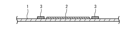
図1及び図2に示す本発明の第一実施形態に係る歪みセンサユニットは、伸縮性を有する基材1と、この基材1に積層され、基材1の伸縮方向に沿って配設される帯状の歪みセンサ2と、この歪みセンサ2の長手方向両端近傍に歪みセンサ2の長手方向に交差する方向に延びるよう配設され、歪みセンサ2よりも曲げ弾性率が大きい1対の変形抑制部3とを備える。
[First Embodiment]
The strain sensor unit according to the first embodiment of the present invention shown in FIGS. 1 and 2 is laminated with a
当該歪みセンサユニットは、例えば人や動物の体の特定の部位の動きを検出するために用いることができる。具体例としては、当該歪みセンサユニットは、人の顔の表情筋や顎関節等の動きを検出するために用いられる。 The strain sensor unit can be used, for example, to detect the movement of a specific part of the human or animal body. As a specific example, the strain sensor unit is used to detect movements of facial muscles, temporomandibular joints, and the like of a human face.
<基材>
基材1は、当該歪みセンサユニットの構造材であり、シート状の材料から形成され、少なくとも歪みセンサ2を保持する部分が帯状に形成される。この基材1は、歪みセンサ2を保持すると共に、測定対象に取り付け可能に構成される。この基材1は、測定対象と共に伸縮し、この伸縮を歪みセンサ2に伝達することによって歪みセンサ2を測定対象と共に伸縮させる機能を果たす。
<Base material>
The
基材1を形成する材料としては、伸縮性を有するものであれば特に限定されないが、例えば不織布、一方向に引き揃えられた縦糸とこの一方向に交差する方向に引き揃えられ縦糸と規則的に組み合わされた横糸とからなる織物、一本又は数本の糸によって多数のループを形成し多数のループが絡み合うように編まれた編物等、これらのいずれかにエラストマーを含浸したシート、繊維を含まないエラストマー製シートなどが挙げられる。これらの中でも、伸縮性の観点から編物によって基材1を形成することが好ましい。
The material for forming the
また、基材1の測定対象への取り付け構造としては、測定対象の外周に装着できるよう基材1が予め環状に形成されてもよく、帯状の基材1の両端を例えば面ファスナー等で貼り合わせることによって装着時に環状にできものであってもよく、帯状の基材1の両端に測定対象の突起部等に引っかけられるフック又はループを有してもよい。具体例として、基材1は、人体に密着するタイツ等の着衣、サポーター、マスク等に類する構造を有するとよい。
Further, as a structure for attaching the
基材1の平均幅の下限としては、1cmが好ましく、1.5cmがより好ましい。一方、基材1の平均幅の上限としては、10cmが好ましく、7cmがより好ましい。基材1の平均幅が前記下限に満たない場合、基材1が面方向に変形して装着位置がずれやすくなるおそれがある。逆に、基材1の平均幅が前記上限を超える場合、当該歪みセンサユニットを装着した被検者の運動を阻害したり違和感を与えるおそれがある。
The lower limit of the average width of the
基材1の平均厚さの下限としては、100μmが好ましく、200μmがより好ましい。一方、基材1の平均厚さの上限としては、2mmが好ましく、1mmがより好ましい。基材1の平均厚さが前記下限に満たない場合、基材1の強度が不十分となるおそれがある。逆に、基材1の平均厚さが前記上限を超える場合、当該歪みセンサユニットを装着した被検者の運動を阻害したり違和感を与えるおそれがある。
The lower limit of the average thickness of the
基材1の目付の下限としては、100g/m2が好ましく、150g/m2がより好ましい。一方、基材1の目付の上限としては、300g/m2が好ましく、250g/m2がより好ましい。基材1の目付が前記下限に満たない場合、基材1の強度が不十分となるおそれがある。逆に、基材1の目付が前記上限を超える場合、基材1の剛性が高くなり、検出感度が不十分となるおそれや、当該歪みセンサユニットを装着した被検者の運動を阻害したり違和感を与えるおそれがある。
As the lower limit of the basis weight of the
基材1の100%伸び荷重(平均長さが2倍になる張力)の下限としては、1Nが好ましく、10Nがより好ましい。一方、基材1の100%伸び荷重の上限としては、10kNが好ましく、1kNがより好ましい。基材1の100%伸び荷重が前記下限に満たない場合、基材1の収縮力が不足し、収縮時の検出に遅れが生じるおそれや、位置ずれにより検出精度が低下するおそれがある。逆に、基材1の100%伸び荷重が前記上限を超える場合、測定する部位の動きを阻害したり、被検者に違和感を与えたりするおそれがある。
As the lower limit of the 100% elongation load (tension that doubles the average length) of the
<歪センサ>
前記歪センサ2は、基材1の表面(測定対象と反対側の面)に重ねられて固定されている。より詳しくは、当該歪みセンサユニットにおいて、歪センサ2は、基材1の短手方向中央に貼設されている。このように、歪センサ2を基材1の中央部に貼設することによって、歪センサ2の周囲の基材1が均等に伸縮し、歪センサ2の位置ずれを抑制できる。
<Distortion sensor>
The
また、歪センサ2は、帯状に形成され、長手方向の伸縮を主に検出するよう構成される。従って当該歪みセンサユニットにおいて、歪センサ2は、基材1の長手方向の伸縮を主に検出する。なお、「長手方向の伸縮を主に検出する」とは、検出値における長手方向の伸縮成分の寄与率が90%以上、好ましくは95%以上であることを意味する。
Further, the
これら歪センサ2としては、伸縮により抵抗値が変化する歪抵抗素子を用いることができ、特に、カーボンナノチューブ(以下、CNTということがある)を用いたCNT歪センサが好適に用いられる。つまり、当該歪みセンサユニットは、歪抵抗素子からなる歪センサ2の抵抗値を不図示の検出回路によって測定することにより、測定対象部位の動きに応じて変化する基材1の伸縮量を検出する。
As these
前記CNT歪センサは、例えば基材1に貼着される伸縮可能なシート状の支持膜と、この支持膜の表面側に積層されるCNT膜と、前記CNT膜を保護する保護膜とを備える構成とすることができる。
The CNT strain sensor includes, for example, a stretchable sheet-shaped support film attached to the
前記CNT歪センサの支持膜の平均厚さとしては、例えば10μm以上5mm以下とすることができる。 The average thickness of the support film of the CNT strain sensor can be, for example, 10 μm or more and 5 mm or less.
この支持膜の材質としては、柔軟性を有する限り特に限定されず、例えば合成樹脂、ゴム、不織布等を挙げることができる。 The material of the support film is not particularly limited as long as it has flexibility, and examples thereof include synthetic resin, rubber, and non-woven fabric.
前記合成樹脂としては、例えばフェノール樹脂(PF)、エポキシ樹脂(EP)、メラミン樹脂(MF)、尿素樹脂(ユリア樹脂、UF)、不飽和ポリエステル(UP)、アルキド樹脂、ポリウレタン(PUR)、熱硬化性ポリイミド(PI)、ポリエチレン(PE)、高密度ポリエチレン(HDPE)、中密度ポリエチレン(MDPE)、低密度ポリエチレン(LDPE)、ポリプロピレン(PP)、ポリ塩化ビニル(PVC)、ポリ塩化ビニリデン、ポリスチレン(PS)、ポリ酢酸ビニル(PVAc)、アクリロニトリルブタジエンスチレン樹脂(ABS)、アクリロニトリルスチレン樹脂(AS)、ポリメチルメタアクリル(PMMA)、ポリアミド(PA)、ポリアセタール(POM)、ポリカーボネート(PC)、変性ポリフェニレンエーテル(m−PPE)、ポリブチレンテレフタレート(PBT)、ポリエチレンテレフタレート(PET)、環状ポリオレフィン(COP)等を挙げることができる。 Examples of the synthetic resin include phenol resin (PF), epoxy resin (EP), melamine resin (MF), urea resin (ureia resin, UF), unsaturated polyester (UP), alkyd resin, polyurethane (PUR), and heat. Curable Polyethylene (PI), Polyethylene (PE), High Density Polyethylene (HDPE), Medium Density Polyethylene (MDPE), Low Density Polyethylene (LDPE), Polypropylene (PP), Polyvinyl Chloride (PVC), Polyvinylidene Chloride, Polystyrene (PS), Polyvinyl acetate (PVAc), Acrylonitrile butadiene styrene resin (ABS), Acrylonitrile styrene resin (AS), Polymethylmethacryl (PMMA), Polyethylene (PA), Polyacetal (POM), Polycarbonate (PC), Modified Examples thereof include polyphenylene ether (m-PPE), polybutylene terephthalate (PBT), polyethylene terephthalate (PET), cyclic polyolefin (COP) and the like.
前記ゴムとしては、例えば天然ゴム(NR)、ブチルゴム(IIR)、イソプレンゴム(IR)、エチレン・プロピレンゴム(EPDM)、ブタジエンゴム(BR)、ウレタンゴム(U)、スチレン・ブタジエンゴム(SBR)、シリコーンゴム(Q)、クロロプレンゴム(CR)、クロロスルフォン化ポリエチレンゴム(CSM)、アクリロニトリルブタジエンゴム(NBR)、塩素化ポリエチレン(CM)、アクリルゴム(ACM)、エピクロルヒドリンゴム(CO,ECO)、フッ素ゴム(FKM)、ポリジメチルシロキサン(PDMS)等を挙げることができる。これらのゴムの中でも強度等の点から天然ゴムが好ましい。 Examples of the rubber include natural rubber (NR), butyl rubber (IIR), isoprene rubber (IR), ethylene / propylene rubber (EPDM), butadiene rubber (BR), urethane rubber (U), and styrene / butadiene rubber (SBR). , Silicone rubber (Q), chloroprene rubber (CR), chlorosulfonized polyethylene rubber (CSM), acrylonitrile butadiene rubber (NBR), chlorinated polyethylene (CM), acrylic rubber (ACM), epichlorohydrin rubber (CO, ECO), Fluoro rubber (FKM), polydimethylsiloxane (PDMS) and the like can be mentioned. Among these rubbers, natural rubber is preferable from the viewpoint of strength and the like.
また、前記CNT歪センサのCNT膜の両端部分には電極が形成され、この電極に配線が例えば導電性接着剤等によって接続される。 Further, electrodes are formed at both ends of the CNT film of the CNT strain sensor, and wiring is connected to the electrodes by, for example, a conductive adhesive.
このCNT膜は、多数のCNT繊維を含有する樹脂組成物で形成される。具体的には、CNT膜は、一方向に配向する複数のCNT繊維からなる複数のCNT繊維束と、この複数のCNT繊維束の周面を被覆する樹脂層とを有する。このようなCNT膜を延伸する歪みが加わった場合に、CNT繊維同士の接触具合に変化が起こり、歪センサとして抵抗変化を得ることができる。なお、より効率よく歪みを検出するには、CNT膜中のCNT繊維が伸縮方向に配向されていることが好ましい。 This CNT film is formed of a resin composition containing a large number of CNT fibers. Specifically, the CNT film has a plurality of CNT fiber bundles composed of a plurality of CNT fibers oriented in one direction, and a resin layer covering the peripheral surface of the plurality of CNT fiber bundles. When the strain that stretches the CNT film is added, the contact condition between the CNT fibers changes, and the resistance change can be obtained as a strain sensor. In order to detect strain more efficiently, it is preferable that the CNT fibers in the CNT film are oriented in the expansion and contraction direction.
CNT膜の無荷重状態での平均厚さの下限としては、1μmが好ましく、10μmがより好ましい。一方、CNT膜の平均厚さの上限としては、1mmが好ましく、0.5mmがさらに好ましい。CNT膜の平均厚さが前記下限に満たない場合、このような薄膜の形成が困難になるおそれや、伸長時に抵抗が上昇し過ぎるおそれがある。逆に、CNT膜の平均厚さが前記上限を超える場合、伸縮性が不十分となるおそれや、伸縮に対する抵抗変化、つまり検出感度が不十分となるおそれや、被検者に違和感を与えるおそれがある。 As the lower limit of the average thickness of the CNT film in the unloaded state, 1 μm is preferable, and 10 μm is more preferable. On the other hand, the upper limit of the average thickness of the CNT film is preferably 1 mm, more preferably 0.5 mm. If the average thickness of the CNT film is less than the lower limit, it may be difficult to form such a thin film, or the resistance may increase too much during elongation. On the contrary, when the average thickness of the CNT film exceeds the upper limit, the elasticity may be insufficient, the resistance to expansion / contraction may be changed, that is, the detection sensitivity may be insufficient, or the subject may feel uncomfortable. There is.
なお、CNT膜は、CNT繊維を平面状に略平行に配置した単層構造からなってもよいし、多層構造からなってもよい。但し、ある程度の導電性を確保するためには、多層構造とすることが好ましい。 The CNT film may have a single-walled structure in which CNT fibers are arranged substantially parallel to each other in a plane, or may have a multi-walled structure. However, in order to secure a certain degree of conductivity, it is preferable to have a multi-layer structure.
CNT繊維としては、単層のシングルウォールナノチューブ(SWNT)や、多層のマルチウォールナノチューブ(MWNT)のいずれも用いることができるが、導電性及び熱容量等の点から、MWNTが好ましく、直径1.5nm以上100nm以下のMWNTがさらに好ましい。 As the CNT fiber, either a single-walled nanotube (SWNT) or a multi-walled nanotube (MWNT) can be used, but MWNT is preferable from the viewpoint of conductivity and heat capacity, and the diameter is 1.5 nm. MWNT of 100 nm or more is more preferable.
また、前記CNT膜の樹脂層は、樹脂を主成分とし、複数のCNT繊維束の周面を被覆する層である。樹脂層の主成分としては、前記支持膜の材料として例示した合成樹脂やゴム等を挙げることができ、これらの中でもゴムが好ましい。ゴムを用いることで、大きな歪みに対してもCNT繊維の十分な保護機能を発揮することができる。また、CNT膜の樹脂層は前記支持膜又は保護膜と一体に形成されてもよい。換言すると、CNT繊維の層に含浸しない樹脂層の厚さを大きくすることによって、支持膜又は保護膜を省略してもよい。 The resin layer of the CNT film is a layer containing resin as a main component and covering the peripheral surfaces of a plurality of CNT fiber bundles. Examples of the main component of the resin layer include synthetic resin and rubber exemplified as the material of the support film, and among these, rubber is preferable. By using rubber, it is possible to exert a sufficient protective function of the CNT fiber even against a large strain. Further, the resin layer of the CNT film may be formed integrally with the support film or the protective film. In other words, the support film or the protective film may be omitted by increasing the thickness of the resin layer that does not impregnate the CNT fiber layer.
このようなCNT歪センサによって形成される歪センサ2の無荷重状態での平均幅の下限としては、0.1mmが好ましく、0.5mmがより好ましい。一方、歪センサ2の平均幅の上限としては、10mmが好ましく、5mmがより好ましい。歪センサ2の平均幅が前記下限に満たない場合、検出感度が不十分となるおそれや、測定対象部位の動きにより歪センサ2が断裂するおそれがある。逆に、歪センサ2の平均幅が前記上限を超える場合、被検者に違和感を与えるおそれがある。
The lower limit of the average width of the
また、歪センサ2の無荷重状態での平均長さは測定対象部位に応じて選択される。一般論として、歪センサ2の無荷重状態での平均長さの下限としては、3mmが好ましく、15mmがより好ましい。一方、歪センサ2の無荷重状態での平均長さの上限としては、70mmが好ましく、50mmがより好ましい。歪センサ2の平均長さが前記下限に満たない場合、基材1のわずかなずれによって検出値が大きく変化し、検出誤差が大きくなるおそれがある。逆に、歪センサ2の平均長さが前記上限を超える場合、検出する動きによって長さが変化しない領域を含むことになり、動きに対する歪センサ2の長さの変化率が小さくなることで検出感度が不十分となるおそれがある。
Further, the average length of the
また、歪センサ2の10%伸び荷重の下限としては、0.01Nが好ましく、0.03Nがより好ましく、0.05Nがさらに好ましい。一方、歪センサ2の10%伸び荷重の上限としては、0.5Nが好ましく、0.3Nがより好ましく、0.2Nがさらに好ましい。歪センサ2の10%伸び荷重が前記下限に満たない場合、測定対象部位の動作以外の要因で伸縮することにより検出精度が不十分となるおそれがある。逆に、歪センサ2の10%伸び荷重が前記上限を超える場合、伸長時の反力が大きくなり、被検者に違和感や拘束感を与えるおそれがある。
The lower limit of the 10% elongation load of the
それぞれの歪センサ2の無荷重状態での抵抗値の下限としては、例えば10Ωが好ましく、100Ωがより好ましい。一方、歪センサ2の無荷重状態での抵抗値の上限としては、100kΩが好ましく、10kΩがより好ましい。歪センサ2の無荷重状態での抵抗値が前記下限に満たない場合、伸びを検出するための電流が大きくなり消費電力が大きくなるおそれがある。逆に、歪センサ2の無荷重状態での抵抗値が前記上限を超える場合、検出回路の電圧が高くなり、小型化及び省電力化が困難となるおそれがある。
As the lower limit of the resistance value of each
それぞれの歪センサ2の伸長による抵抗値の変化率は、十分な検出精度が得られるよう適宜選択されるものであるが、歪センサ2の無荷重状態での抵抗値に対する10%延伸した状態での抵抗値の比としては、例えば1.5倍以上20倍以下とされる。
The rate of change of the resistance value due to the elongation of each
基材1への歪センサ2の貼着は、基材1及び歪センサ2の伸縮を阻害しないこと、具体的には伸び荷重が十分に小さい接着剤を用いることが好ましい。このような伸び荷重が小さい接着剤としては、例えば湿気硬化型ポリウレタン接着剤等が挙げられる。
For attachment of the
<変形抑制部>
1対の変形抑制部3は、歪みセンサ2の長手方向両端部の基材1の変形を抑制することにより、1対の変形抑制部3の間の基材1の反り返りを防止して測定対象への密着性を向上することで、歪みセンサ2の位置ずれを抑制する。
<Deformation suppression unit>
The pair of
本実施形態における変形抑制部3は、歪みセンサ2と重ならないようわずかに隙間を空けて配設されている。このように、変形抑制部3を歪みセンサ2から離間して配設することにより、平面視で変形抑制部3が傾斜した場合に歪みセンサ2に加わる応力を抑制することができる。
The
また、変形抑制部3は、例えば人体表面の凹部に基材1の変形抑制部3配設部分が嵌まり込むような形状となるよう、測定対象の凹凸に合わせて形状を選択することにより、変形抑制部3の測定対象に対する位置ずれを効果的に抑制できる。このため、変形抑制部3は、無負荷状態で基材1を歪みセンサ2の長手方向と垂直な方向の断面視で湾曲させるように屈曲していてもよい。
Further, the
変形抑制部3の構成としては、基材1に他の部材を取り付けることで剛性を大きくした構成であってもよく、例えば糸の縫い付け、樹脂組成物の塗布等によって基材1の変形を抑制するものであってもよい。また、バネ性を有する糸状又は板状の部材を配置してもよい。
The
変形抑制部3は、歪みセンサ2の長手方向に交差する方向に延びる帯状に形成されることが好ましい。このように、変形抑制部3が帯状に形成されることにより、変形抑制部3の占有面積を小さくしつつ効果的に基材1の変形を抑制できるので、当該歪みセンサユニットの装着性を損なうことなく、歪みセンサ2の位置ずれを防止することができる。
The
変形抑制部3は、歪みセンサ2の長手方向に交差する方向の基材1の伸縮を防止できるものであることが好ましい。具体的には、変形抑制部3は、歪みセンサ2の長手方向に交差する方向の中心軸を有する密巻きコイルバネを含むとよい。密巻きコイルバネは、隙間を空けずにワイヤを巻回して形成される弦巻きバネであって、長さ方向(中心軸方向)に圧縮不能である。また、ワイヤの曲げ弾性率を選択することで、当該歪みセンサユニットの使用に際して実質的に伸長せず、測定対象の表面形状に合わせる程度に屈曲することは可能としつつ、基材1が反り返るような大きな変形を防止して基材1が測定対象に対して滑りやすくなることを防止することができる。
It is preferable that the
密巻きコイルバネは、例えば布帛、エラストマー樹脂シート等のシート状の材料に固定されていることが好ましい。具体的には、密巻きコイルバネが1対の布帛又はエラストマー樹脂シートによって挟み込まれていてもよく、1枚の布帛又はエラストマー樹脂シートに接着又は縫い付けされていてもよい。このように、密巻きコイルバネがシート状の材料に固定されていることによって、基材1に対して比較的容易に固定することができるので、変形抑制部3を形成しやすくなる。
The tightly wound coil spring is preferably fixed to a sheet-like material such as a cloth or an elastomer resin sheet. Specifically, the tightly wound coil spring may be sandwiched between a pair of fabrics or an elastomer resin sheet, or may be adhered or sewn to a single fabric or an elastomer resin sheet. Since the tightly wound coil spring is fixed to the sheet-like material in this way, it can be relatively easily fixed to the
変形抑制部3の歪みセンサ2の長手方向に直交する方向の最大長さの下限としては、歪みセンサ2の平均幅の5倍が好ましく、10倍がより好ましい。一方、変形抑制部3の歪みセンサ2の長手方向に直交する方向の最大長さの上限としては、歪みセンサ2の平均幅の100倍が好ましく、50倍がより好ましい。変形抑制部3の歪みセンサ2の長手方向に直交する方向の最大長さが前記下限に満たない場合、歪みセンサ2の位置ずれを十分に抑制できないおそれがある。逆に、変形抑制部3の歪みセンサ2の長手方向に直交する方向の最大長さが前記上限を超える場合、当該歪みセンサユニットの幅が不必要に大きくなることで被検者に違和感や拘束感を与えるおそれがある。
The lower limit of the maximum length in the direction orthogonal to the longitudinal direction of the
変形抑制部3の歪みセンサ2の長手方向の幅の下限としては、特に限定されず、変形抑制部3の剛性が十分大きくなる幅とすればよい。一方、変形抑制部3の歪みセンサ2の長手方向の幅の上限としては、歪みセンサ2の平均長さの1倍が好ましく、0.5倍がより好ましい。変形抑制部3の歪みセンサ2の長手方向の幅が前記上限を超える場合、当該歪みセンサユニットの幅が不必要に大きくなることで被検者に違和感や拘束感を与えるおそれがある。
The lower limit of the width of the
変形抑制部3の曲げ弾性率は、その断面積等によっても異なるが、歪みセンサ2よりも大きく、かつ基材1の反り返りを防止できる大きさとされる。具体的には、変形抑制部3の曲げ弾性率の下限としては、1kPaが好ましく、10kPaがより好ましい。一方、変形抑制部3の曲げ弾性率の上限としては、10MPaが好ましく、1MPaがより好ましい。変形抑制部3の曲げ弾性率が前記下限に満たない場合、基材1の反り返りを防止できないことで歪みセンサ2の位置ずれを抑制できないおそれがある。逆に、変形抑制部3の曲げ弾性率が前記上限を超える場合、基材1が測定対象に密着しないことで被験者(体の動きを測定される者)に違和感や拘束感を与えるおそれがある。
The flexural modulus of the
<利点>
当該歪みセンサユニットは、歪みセンサ2の長手方向両端近傍に曲げ弾性率が大きい1対の変形抑制部3を備えることによって、歪みセンサ2の両側の基材1が変形しにくいので、歪みセンサ2の位置ずれが抑制されることで比較的検出精度が高い。
<Advantage>
Since the strain sensor unit is provided with a pair of
[第二実施形態]
図3及び図4に示す本発明の第二実施形態に係る歪みセンサユニットは、伸縮性を有する基材1と、この基材1に積層され、基材1の伸縮方向に沿って配設される帯状の歪みセンサ2と、この歪みセンサ2の長手方向両端近傍に歪みセンサ2の長手方向に交差する方向に延びるよう配設され、歪みセンサ2よりも曲げ弾性率が大きい1対の変形抑制部3aと、基材1の裏面の平面視で歪みセンサ2の長手方向両側に配設される1対の滑り止め4を備える。
[Second Embodiment]
The strain sensor unit according to the second embodiment of the present invention shown in FIGS. 3 and 4 is laminated with a
図3及び図4の歪みセンサユニットにおける基材1及び歪みセンサ2の構成は、図1及び図2の歪みセンサユニットにおける基材1及び歪みセンサ2の構成と同様とすることができる。このため、図3及び図4の歪みセンサユニットについて、図1及び図2の歪みセンサユニットと同じ構成要素には同じ符号を付して重複する説明を省略する。
The configurations of the
<変形抑制部>
図3及び図4の歪みセンサユニットにおける変形抑制部3aは、歪みセンサ2の端部に重畳されるよう配設される点を除いて、図1及び図2の歪みセンサユニットにおける変形抑制部3と同様である。
<Deformation suppression unit>
The
当該歪みセンサユニットでは、変形抑制部3aが歪みセンサ2の端部に重畳されるよう配設されるので、1対の変形抑制部3a間の距離が比較的小さくなることから歪みセンサ2の位置ずれをより確実に抑制することができる。
In the strain sensor unit, since the
<滑り止め>
滑り止め4は、基材1の裏面に積層され、測定対象との摩擦を増大して、基材1ひいて場歪みセンサ2が位置ずれすることをより確実に抑制する。
<Non-slip>
The non-slip 4 is laminated on the back surface of the
滑り止め4は、平面視で変形抑制部3aと重複するよう配設されてもよく、変形抑制部3aのさらに外側に配設されてもよい。
The non-slip 4 may be arranged so as to overlap the
滑り止め4の材質としては、例えば合成ゴム、天然ゴム等を用いることができる。また、滑り止め4に平面形状としては、特に限定されず、例えば方形、円形等任意の形状とすることができ、基材1を部分的に露出又は部分的に被覆するパターン状であってもよい。
As the material of the non-slip 4, for example, synthetic rubber, natural rubber, or the like can be used. Further, the planar shape of the non-slip 4 is not particularly limited, and may be any shape such as a square or a circular shape, even if the
滑り止め4は、基材1の裏面に接着されてもよく、基材1の裏面に樹脂組成物を塗工することにより形成されてもよい。
The non-slip 4 may be adhered to the back surface of the
滑り止め4の歪みセンサ2の長手方向の平均長さの下限としては、1mmが好ましく、3mmがより好ましい。一方、滑り止め4の歪みセンサ2の長手方向の平均長さの上限としては、50mmが好ましく、30mmがより好ましい。滑り止め4の歪みセンサ2の長手方向の平均長さが前記下限に満たない場合、摩擦を増大できずに歪みセンサ2の位置ずれ抑制効果を促進できないおそれがある。逆に、滑り止め4の歪みセンサ2の長手方向の平均長さが前記上限を超える場合、当該歪みセンサユニットが不必要に大きくなるおそれがある。
The lower limit of the average length of the
滑り止め4の歪みセンサ2の長手方向に垂直な方向の平均長さの下限としては、3mmが好ましく、5mmがより好ましい。一方、滑り止め4の歪みセンサ2の長手方向に垂直な方向の平均長さの上限としては、変形抑制部3aの長さの1.2倍が好ましく、変形抑制部3aの長さの1倍がより好ましい。滑り止め4の歪みセンサ2の長手方向に垂直な方向の平均長さが前記下限に満たない場合、摩擦を増大できずに歪みセンサ2の位置ずれ抑制効果を促進できないおそれがある。逆に、滑り止め4の歪みセンサ2の長手方向に垂直な方向の平均長さが前記上限を超える場合、当該歪みセンサユニットが不必要に大きくなるおそれがある。
As the lower limit of the average length in the direction perpendicular to the longitudinal direction of the
[第三実施形態]
図5に示す本発明の第三実施形態に係る歪みセンサユニットは、伸縮性を有する基材1bと、この基材1bに積層され、基材1bの伸縮方向に沿って平行に配設される複数(2つ)の歪みセンサ2と、この複数歪みセンサ2の長手方向両端近傍に歪みセンサ2の長手方向に交差する方向に延びるよう配設され、歪みセンサ2よりも曲げ弾性率が大きい1対の変形抑制部3とを備える。
[Third Embodiment]
The strain sensor unit according to the third embodiment of the present invention shown in FIG. 5 is laminated on the
図5の歪みセンサユニットにおける歪みセンサ2及び変形抑制部3の構成は、図1及び図2の歪みセンサユニットにおける歪みセンサ2及び変形抑制部3の構成と同様とすることができる。このため、図5の歪みセンサユニットについて、図1及び図2の歪みセンサユニットと同じ構成要素には同じ符号を付して重複する説明を省略する。
The configuration of the
<基材>
基材1bは、複数の歪みセンサ2の間に、これらの歪みセンサ2と平行なスリット5を有する。
<Base material>
The
(スリット)
スリット5は、複数の歪みセンサ2間で基材1bを分断することにより、複数の歪みセンサ2が互いに独立して伸縮できるようにする。つまり、当該歪みセンサユニットは、1つの歪みセンサ2の変位が他の歪みセンサ2の変位に影響を及ぼしにくいので、比較的検出精度が高い。
(slit)
The
スリット5の長さの下限としては、歪みセンサ2の幅方向中心線の長さの1/2が好ましく、2/3がより好ましい。一方、スリット5の長さの上限としては、歪みセンサ2の幅方向中心線の長さの1.2倍が好ましく、1倍がより好ましい。スリット5の長さが前記下限に満たない場合、歪みセンサ2間の相互干渉を十分に低減できないおそれがある。逆に、スリット5の長さが前記上限を超える場合、当該歪みセンサユニットが不必要に大きくなるおそれや、変形抑制部3により歪みセンサ2の位置ずれを抑制する効果が小さくなるおそれがある。
As the lower limit of the length of the
[その他の実施形態]
前記実施形態は、本発明の構成を限定するものではない。従って、前記実施形態は、本明細書の記載及び技術常識に基づいて前記実施形態各部の構成要素の省略、置換又は追加が可能であり、それらは全て本発明の範囲に属するものと解釈されるべきである。
[Other Embodiments]
The embodiment does not limit the configuration of the present invention. Therefore, it is possible to omit, replace or add components of each part of the embodiment based on the description of the present specification and common general technical knowledge, and all of them are construed to belong to the scope of the present invention. Should be.
当該歪みセンサユニットは、図6に示すように、1対の変形抑制部3cが歪みセンサ2の長手方向に垂直な方向に対して傾斜していてもよく、図7に示すように、1対の変形抑制部3dが互いに歪みセンサ2の長手方向に対して異なる傾斜角度で傾斜して配置されてもよい。
In the strain sensor unit, as shown in FIG. 6, a pair of
また、当該歪みセンサユニットは、図8に示すように、変形抑制部3eが屈曲又は湾曲していてもよい。
Further, in the strain sensor unit, as shown in FIG. 8, the
当該歪みセンサユニットにおいて、例えば図9に示すように、変形抑制部3fの平面形状が、歪センサ2の長さ方向に長いものであってもよい。つまり、当該歪みセンサユニットにおける変形抑制部は、平面視で歪センサの長手方向に垂直な方向の長さが歪みセンサの幅よりも大きければよい。
In the strain sensor unit, for example, as shown in FIG. 9, the planar shape of the
当該歪みセンサユニットは、平行に配設される3つ以上の歪みセンサを備えてもよい。また、当該歪みセンサユニットは、平行に配設される複数の歪みセンサを有する場合であっても、基材にスリットが形成されていなくてもよい。 The strain sensor unit may include three or more strain sensors arranged in parallel. Further, even when the strain sensor unit has a plurality of strain sensors arranged in parallel, the slit may not be formed in the base material.
当該歪みセンサユニットにおいて、基材は帯状でなくてもよく、例えばマスク、シャツ等に準じた人体に密着する任意の形状を有してもよい。 In the strain sensor unit, the base material does not have to be strip-shaped, and may have an arbitrary shape that adheres to the human body, such as a mask or shirt.
当該歪みセンサユニットにおいて、歪みセンサは、基材の短手方向中央からずれた位置に配設されてもよい。 In the strain sensor unit, the strain sensor may be arranged at a position deviated from the center in the lateral direction of the base material.
当該歪みセンサユニットにおいて、変形抑制部は、基材の裏面側に積層されてもよく、この場合、変形抑制部が滑り止めを兼ねてもよい。 In the strain sensor unit, the deformation suppressing portion may be laminated on the back surface side of the base material, and in this case, the deformation suppressing portion may also serve as a non-slip.
1つの基材上に複数の歪みセンサと各歪みセンサの長手方向両側にそれぞれ1対の変形抑制部が配設されてもよい。例えばマスク状の基材に複数の表情筋等の動きを検出するために異なる形状の複数の歪みセンサ及び変形抑制部の組を異なる向きに配置してもよい。 A plurality of strain sensors and a pair of deformation suppression portions may be arranged on both sides of each strain sensor in the longitudinal direction on one substrate. For example, in order to detect the movement of a plurality of facial muscles or the like on a mask-like base material, a plurality of strain sensors having different shapes and a set of deformation suppressing portions may be arranged in different directions.
当該歪みセンサユニットは、人体以外に、例えば動物、機械等の動きを検出するために用いてもよい。 The strain sensor unit may be used to detect the movement of an animal, a machine, or the like in addition to the human body.
本発明に係る歪みセンサユニットは、特に人体の動きを検出するために好適に利用することができる。 The strain sensor unit according to the present invention can be suitably used particularly for detecting the movement of the human body.
1,1b 基材
2 歪みセンサ
3,3a,3c,3d,3e,3f 変形抑制部
4 滑り止め
5 スリット
1,
Claims (5)
前記基材に積層され、前記基材の伸縮方向に沿って配設される帯状の1又は複数の歪みセンサ素子と、
前記1又は複数の歪みセンサ素子の長手方向両端部近傍に歪みセンサ素子の幅方向に延びるよう前記基材に配設され、前記歪みセンサ素子よりも曲げ弾性率が大きく、上記基材の変形を抑制する1対の変形抑制部と
を備え、
前記1対の変形抑制部が前記1又は複数の歪みセンサ素子から離間して配設され、
前記変形抑制部の前記歪みセンサ素子の幅方向の長さが前記歪みセンサ素子の平均幅以上である歪みセンサユニット。 With elastic base material,
A strip-shaped strain sensor element laminated on the base material and arranged along the expansion and contraction direction of the base material, and
Wherein one or more disposed in said substrate so as to extend in the width direction of the strain sensor element in the longitudinal direction near both ends of the strain sensor element, the strain sensor flexural modulus than the element is rather large, the deformation of the substrate and a deformation suppressing portion of the pair inhibit,
The pair of deformation suppressing portions are arranged apart from the one or a plurality of strain sensor elements .
Der Ruyugami sensor unit average width or more of the strain sensor width direction of length the strain sensor element of the device of the deformation suppression portion.
前記基材が前記複数の歪みセンサ素子の間に歪みセンサ素子と平行なスリットを有する請求項1又は請求項2に記載の歪みセンサユニット。 A plurality of the strain sensor elements are arranged in parallel,
The strain sensor unit according to claim 1 or 2, wherein the base material has a slit parallel to the strain sensor element between the plurality of strain sensor elements .
Priority Applications (4)
| Application Number | Priority Date | Filing Date | Title |
|---|---|---|---|
| JP2016094481A JP6759689B2 (en) | 2016-05-10 | 2016-05-10 | Distortion sensor unit |
| CN201780028543.6A CN109073353B (en) | 2016-05-10 | 2017-04-28 | Strain sensor unit |
| PCT/JP2017/017068 WO2017195683A1 (en) | 2016-05-10 | 2017-04-28 | Strain sensor unit |
| US16/185,147 US11175124B2 (en) | 2016-05-10 | 2018-11-09 | Strain sensor unit |
Applications Claiming Priority (1)
| Application Number | Priority Date | Filing Date | Title |
|---|---|---|---|
| JP2016094481A JP6759689B2 (en) | 2016-05-10 | 2016-05-10 | Distortion sensor unit |
Publications (3)
| Publication Number | Publication Date |
|---|---|
| JP2017203656A JP2017203656A (en) | 2017-11-16 |
| JP2017203656A5 JP2017203656A5 (en) | 2019-06-06 |
| JP6759689B2 true JP6759689B2 (en) | 2020-09-23 |
Family
ID=60266568
Family Applications (1)
| Application Number | Title | Priority Date | Filing Date |
|---|---|---|---|
| JP2016094481A Active JP6759689B2 (en) | 2016-05-10 | 2016-05-10 | Distortion sensor unit |
Country Status (4)
| Country | Link |
|---|---|
| US (1) | US11175124B2 (en) |
| JP (1) | JP6759689B2 (en) |
| CN (1) | CN109073353B (en) |
| WO (1) | WO2017195683A1 (en) |
Families Citing this family (8)
| Publication number | Priority date | Publication date | Assignee | Title |
|---|---|---|---|---|
| CN113016237A (en) * | 2018-11-16 | 2021-06-22 | 大日本印刷株式会社 | Wiring board and method for manufacturing wiring board |
| JP6696634B1 (en) * | 2018-11-16 | 2020-05-20 | 大日本印刷株式会社 | Wiring board and method for manufacturing wiring board |
| CN113454417B (en) * | 2019-02-12 | 2023-10-20 | 株式会社村田制作所 | strain sensor |
| TWI723587B (en) * | 2019-10-17 | 2021-04-01 | 國立中央大學 | Dynamic strain type cable force monitor and monitoring method thereof |
| JP2022021252A (en) * | 2020-07-21 | 2022-02-02 | ヤマハ株式会社 | Biological sensor |
| CN112161738B (en) * | 2020-09-17 | 2022-04-08 | 五邑大学 | Air pressure sensor and manufacturing method thereof |
| CN112525061B (en) * | 2020-11-09 | 2022-09-13 | 西南科技大学 | Wireless strain testing device and method adopting nano composite material |
| CA3211603A1 (en) * | 2021-03-26 | 2022-09-29 | Greg BIDDULPH | Device and method for monitoring compression level of a compression garment |
Family Cites Families (17)
| Publication number | Priority date | Publication date | Assignee | Title |
|---|---|---|---|---|
| JP2000159052A (en) * | 1998-11-20 | 2000-06-13 | Fujikura Ltd | Film antenna, seating sensor using it, and air bag control device using sensor |
| JP4013149B2 (en) * | 2004-03-10 | 2007-11-28 | 清水建設株式会社 | Structure soundness judgment device |
| US7791476B2 (en) | 2006-02-21 | 2010-09-07 | Elesys North America, Inc. | Occupant sensor and method for seat belt or other monitoring |
| FR2904590A1 (en) * | 2006-08-02 | 2008-02-08 | Aisin Seiki | SENSOR FOR DETECTING GLASS CASSING |
| JP5397896B2 (en) | 2009-08-25 | 2014-01-22 | 独立行政法人産業技術総合研究所 | EXTENSION DEVICE, EXTENSION DRIVE DEVICE, AND CNT FILM STRUCTURE USING CARBON NANOTUBE |
| JP5924725B2 (en) * | 2011-11-14 | 2016-05-25 | ヤマハ株式会社 | Strain sensor and method for manufacturing strain sensor |
| US10265019B2 (en) * | 2013-03-29 | 2019-04-23 | Oxystrap Int'l, Inc. | Electronic headwear |
| JP5764609B2 (en) * | 2013-05-08 | 2015-08-19 | 富士重工業株式会社 | Bush component force detector |
| EP2801549B1 (en) * | 2013-05-10 | 2018-01-31 | Yamaha Corporation | Strain sensor based on carbon nanotubes and method for its manufacture |
| JP5839150B2 (en) * | 2013-05-24 | 2016-01-06 | 日立金属株式会社 | Pressure sensor, mass flow meter and mass flow controller using the same |
| US10209055B2 (en) * | 2014-03-03 | 2019-02-19 | Bando Chemical Industries, Ltd. | Sensor device and stretchable structure |
| WO2016060031A1 (en) * | 2014-10-17 | 2016-04-21 | ヤマハ株式会社 | Data glove |
| EP3208687B1 (en) | 2014-10-17 | 2019-11-27 | Yamaha Corporation | Data glove |
| JP6488140B2 (en) * | 2015-02-06 | 2019-03-20 | 日本メクトロン株式会社 | Conductive stretchable substrate and strain sensor |
| JP6325482B2 (en) * | 2015-04-06 | 2018-05-16 | バンドー化学株式会社 | Capacitance type sensor sheet and sensor device |
| JP6506653B2 (en) * | 2015-07-30 | 2019-04-24 | 日本メクトロン株式会社 | Stretchable wiring board |
| CN105486218B (en) * | 2016-01-12 | 2019-07-02 | 山东大学 | It is a kind of to monitor the smart material strain gauge and application that bituminous pavement strains |
-
2016
- 2016-05-10 JP JP2016094481A patent/JP6759689B2/en active Active
-
2017
- 2017-04-28 CN CN201780028543.6A patent/CN109073353B/en active Active
- 2017-04-28 WO PCT/JP2017/017068 patent/WO2017195683A1/en active Application Filing
-
2018
- 2018-11-09 US US16/185,147 patent/US11175124B2/en active Active
Also Published As
| Publication number | Publication date |
|---|---|
| JP2017203656A (en) | 2017-11-16 |
| CN109073353A (en) | 2018-12-21 |
| WO2017195683A1 (en) | 2017-11-16 |
| US11175124B2 (en) | 2021-11-16 |
| US20190094004A1 (en) | 2019-03-28 |
| CN109073353B (en) | 2022-03-18 |
Similar Documents
| Publication | Publication Date | Title |
|---|---|---|
| JP6759689B2 (en) | Distortion sensor unit | |
| JP6264825B2 (en) | Fabric and clothing with strain sensor | |
| JP6014906B2 (en) | Strain sensor | |
| JP6019890B2 (en) | Fabric and clothing with strain sensor | |
| JP2017075847A (en) | Movement detection device | |
| JP6341268B2 (en) | Gloves with strain sensor | |
| CN107077207B (en) | Data glove | |
| JP6701748B2 (en) | Strain sensor element | |
| US20190072440A1 (en) | Fibre-based sensor for yarn | |
| US20110125064A1 (en) | Smart clothing for motion physiological measurement and dynamical stable apparatus thereof | |
| JP6702709B2 (en) | Clothing | |
| JP6470049B2 (en) | Yarn-like strain sensor element and fabric-like strain sensor element | |
| JP6488131B2 (en) | Foot motion detection supporter | |
| JP2016121975A (en) | Distortion detection sensor element and external force detection array module | |
| WO2018047718A1 (en) | Anisotropic strain sensor sheet and clothing | |
| JP6848458B2 (en) | Sensor unit | |
| JP6821949B2 (en) | Distortion sensor unit | |
| JP6561640B2 (en) | Strain sensor element | |
| JP6687131B2 (en) | Tactile sensor | |
| US20230148077A1 (en) | Motion detection member | |
| JP2016176874A (en) | Strain sensor element | |
| JP2017164296A (en) | Action detection device | |
| JP2017211214A (en) | Strain sensor and strain sensor unit | |
| WO2022019024A1 (en) | Biometric sensor | |
| JP7467828B2 (en) | Strain sensor unit and extension amount measuring member |
Legal Events
| Date | Code | Title | Description |
|---|---|---|---|
| A621 | Written request for application examination |
Free format text: JAPANESE INTERMEDIATE CODE: A621 Effective date: 20190322 |
|
| A521 | Request for written amendment filed |
Free format text: JAPANESE INTERMEDIATE CODE: A523 Effective date: 20190424 |
|
| A131 | Notification of reasons for refusal |
Free format text: JAPANESE INTERMEDIATE CODE: A131 Effective date: 20191203 |
|
| A521 | Request for written amendment filed |
Free format text: JAPANESE INTERMEDIATE CODE: A523 Effective date: 20200127 |
|
| TRDD | Decision of grant or rejection written | ||
| A01 | Written decision to grant a patent or to grant a registration (utility model) |
Free format text: JAPANESE INTERMEDIATE CODE: A01 Effective date: 20200804 |
|
| A61 | First payment of annual fees (during grant procedure) |
Free format text: JAPANESE INTERMEDIATE CODE: A61 Effective date: 20200817 |
|
| R151 | Written notification of patent or utility model registration |
Ref document number: 6759689 Country of ref document: JP Free format text: JAPANESE INTERMEDIATE CODE: R151 |