JP6019890B2 - Fabric and clothing with strain sensor - Google Patents
Fabric and clothing with strain sensor Download PDFInfo
- Publication number
- JP6019890B2 JP6019890B2 JP2012167736A JP2012167736A JP6019890B2 JP 6019890 B2 JP6019890 B2 JP 6019890B2 JP 2012167736 A JP2012167736 A JP 2012167736A JP 2012167736 A JP2012167736 A JP 2012167736A JP 6019890 B2 JP6019890 B2 JP 6019890B2
- Authority
- JP
- Japan
- Prior art keywords
- fabric
- strain sensor
- fabric body
- cnt
- wiring
- Prior art date
- Legal status (The legal status is an assumption and is not a legal conclusion. Google has not performed a legal analysis and makes no representation as to the accuracy of the status listed.)
- Active
Links
Images


Landscapes
- Measurement Of Length, Angles, Or The Like Using Electric Or Magnetic Means (AREA)
- Professional, Industrial, Or Sporting Protective Garments (AREA)
- Knitting Of Fabric (AREA)
- Woven Fabrics (AREA)
Description
この発明は、歪みセンサ付き布帛及び被服に関する。 The present invention relates to a fabric with a strain sensor and clothing.
歪みセンサが付設された被服は、着用者の動作を電気信号として捉えることができる。このような被服としては、例えば特開2011−47702号公報所載のものが公知である。この公報所載の被服は、所定方向に配向されたカーボンナノチューブ膜を有する歪みセンサが基材に付設されている。そして、この公報所載の被服にあっては、基材の伸縮に伴ってカーボンナノチューブ膜が伸縮されると、歪みセンサの電極に接続された配線を介して検知信号が伝達され、この検知信号を判定することで基材の変形を検出して、これにより着用者の動作を検知するものである。 Clothing provided with a strain sensor can capture the wearer's movement as an electrical signal. As such clothes, for example, those described in JP 2011-47702 A are known. In the clothing described in this publication, a strain sensor having a carbon nanotube film oriented in a predetermined direction is attached to a base material. In the clothing described in this publication, when the carbon nanotube film is expanded and contracted along with the expansion and contraction of the base material, a detection signal is transmitted through the wiring connected to the electrode of the strain sensor. By detecting the deformation of the base material, thereby detecting the wearer's movement.
上記公報所載の被服にあっては、配線は一端が歪みセンサの電極に接続されているが、その他の部分は基材等に固定されない状態であり、この配線が着用者の動作の邪魔となるおそれがある。また、着用者の身体の動きによって配線に張力が生じると、配線が断線するおそれがある。 In the clothing described in the above publication, one end of the wiring is connected to the electrode of the strain sensor, but the other part is not fixed to the substrate or the like, and this wiring is an obstacle to the wearer's operation. There is a risk. Moreover, when tension | tensile_strength arises in wiring by a wearer's body movement, there exists a possibility that wiring may be disconnected.
特に、上記公報所載の手袋のように多数の歪みセンサを付設した被服にあっては、配線が多数存在するため、着用者の手の動きの邪魔となるという問題が顕著である。さらには、複数の配線が存在することで、配線同士が絡まり、配線が断線するおそれがある。 In particular, in a garment provided with a large number of strain sensors, such as the glove described in the above publication, there is a significant problem that it interferes with the movement of the wearer's hand because there are many wires. Furthermore, the presence of a plurality of wires may cause the wires to get tangled and the wires to be disconnected.
本発明は、このような事情に基づいてなされものであり、本発明の課題は、布帛本体を伸縮させる動作等に対して配線が邪魔となりにくく、配線が断線しにくい歪みセンサ付き布帛を提供することにあり、また着用者の動作の妨げとなりにくく、着用者の動作による断線が生じにくい被服を提供することにある。 The present invention has been made based on such circumstances, and an object of the present invention is to provide a fabric with a strain sensor in which the wiring is less likely to interfere with the operation of expanding and contracting the fabric body and the wiring is less likely to break. In particular, it is an object of the present invention to provide a clothing that is unlikely to obstruct the wearer's movement and is less likely to be disconnected by the wearer's movement.
前記課題を解決すべくなされた本発明に係る歪みセンサ付き布帛は、
伸縮可能な布帛本体と、この布帛本体に付設され、布帛本体の伸縮に追従可能な歪みセンサとを有する歪みセンサ付き布帛であって、
前記歪みセンサに電気的に接続されるとともに前記布帛本体に一体的に設けられ且つ布帛本体の伸縮に追従して変形する配線部を備えることを特徴とする。
The fabric with a strain sensor according to the present invention, which has been made to solve the above problems,
A fabric with a strain sensor, comprising a fabric body that can be stretched and a strain sensor attached to the fabric body and capable of following the stretch of the fabric body,
A wiring portion is provided which is electrically connected to the strain sensor and is provided integrally with the fabric body and deforms following the expansion and contraction of the fabric body.
当該歪みセンサ付き布帛は、布帛本体の伸縮に伴って歪みセンサが伸縮されると、歪みセンサに電気的に接続された配線部を介して検知信号が伝達され、この検知信号によって布帛の伸縮を測定可能である。上記配線部は、布帛本体に一体的に設けられているので、布帛本体を伸縮させる動作に対して配線部が邪魔になりにくい。また、上記配線部は、布帛本体の伸縮に追従して変形するので、布帛本体の伸縮を妨げず、上述の布帛本体を伸縮させる動作に際して追従して布帛本体が伸縮しやすい。さらに、このように配線部が布帛本体に一体的に設けられているとともに布帛本体の伸縮に追従して変形するので、配線部自体が断線しにくい。 When the strain sensor is expanded and contracted as the fabric body expands and contracts, a detection signal is transmitted to the fabric with the strain sensor via a wiring portion electrically connected to the strain sensor. It can be measured. Since the wiring portion is provided integrally with the fabric body, the wiring portion is unlikely to interfere with the operation of expanding and contracting the fabric body. Moreover, since the said wiring part deform | transforms following the expansion / contraction of a fabric main body, it does not prevent expansion / contraction of a fabric main body, but follows the operation | movement which expands / contracts the above-mentioned fabric main body, and a fabric main body tends to expand / contract. Furthermore, since the wiring portion is integrally provided on the fabric body and is deformed following the expansion and contraction of the fabric body, the wiring portion itself is not easily disconnected.
当該歪みセンサ付き布帛は、配線部が、導電性を有する糸状体を布帛本体に縫い付けることで形成されている構成を採用可能である。これにより、糸状体を縫い付けることで容易に配線部を容易且つ確実に形成することができる。 The fabric with the strain sensor can employ a configuration in which the wiring portion is formed by sewing a conductive filamentous body to the fabric body. Thereby, a wiring part can be easily and reliably formed by sewing a threadlike body easily.
当該歪みセンサ付き布帛は、布帛本体が、導電性を有さない糸状体を編成又は織成されることで形成された布からなり、配線部が、布帛本体の編成又は織成に際して前記導電性を有さない糸状体とともに導電性を有する糸状体を編成又は織成することで形成されている構成を採用可能である。これにより、布帛本体の編成又は織成に際して布帛本体を構成する導電性を有さない糸状体とともに導電性を有する糸状体をも使用することで配線部を容易且つ確実に形成することができる。 The fabric with a strain sensor is made of a fabric formed by knitting or weaving a thread-like body having no electrical conductivity, and the wiring portion is electrically conductive when the fabric body is knitted or woven. It is possible to adopt a configuration formed by knitting or weaving a conductive filamentous body together with a filamentous body that does not have a thread. As a result, the wiring portion can be easily and reliably formed by using the conductive filamentous body together with the non-conductive filamentous body constituting the fabric body when the fabric body is knitted or woven.
当該歪みセンサ付き布帛は、布帛本体の一方の面に付設された帯状部材から形成されている構成を採用可能である。これにより、帯状部材を布帛本体に付設することで配線部を容易且つ確実に形成することができる。 The fabric with the strain sensor can employ a configuration formed of a band-like member attached to one surface of the fabric body. Thereby, a wiring part can be formed easily and reliably by attaching a strip | belt-shaped member to a fabric main body.
本発明に係る被服は、上記構成からなる当該歪みセンサ付き布帛を備えている。これにより、当該被服の着用者の動作によって歪みセンサが伸縮されると、歪みセンサに電気的に接続された配線部を介して検知信号が伝達され、この検知信号によって着用者の動作を検知することできる。当該被服にあっては配線部が布帛本体の伸縮に追従して変形するので、配線部が布帛本体の伸縮を妨げず、着用者の動作の邪魔になりにくい。さらに、このように配線部が布帛本体に一体的に取付けられ且つ変形可能に設けられているので、配線部自体が断線しにくい。 The clothing according to the present invention includes the fabric with the strain sensor having the above-described configuration. Accordingly, when the strain sensor is expanded and contracted by the operation of the wearer of the clothing, a detection signal is transmitted through the wiring portion electrically connected to the strain sensor, and the operation of the wearer is detected by the detection signal. I can. In the clothing, since the wiring portion deforms following the expansion and contraction of the fabric body, the wiring portion does not hinder the expansion and contraction of the fabric body and is unlikely to obstruct the wearer's operation. Furthermore, since the wiring portion is integrally attached to the fabric body and is deformable as described above, the wiring portion itself is not easily disconnected.
以上説明したように、本発明の歪みセンサ付き布帛は、布帛本体を伸縮させる動作に対して配線が邪魔となりにくく、配線が断線しにくい。また、本発明に係る被服は、着用者の動作の妨げとなりにくく、着用者の動作による断線が生じにくい。 As described above, in the fabric with a strain sensor of the present invention, the wiring is less likely to interfere with the operation of expanding and contracting the fabric body, and the wiring is less likely to break. Moreover, the clothes which concern on this invention do not become easy to obstruct a wearer's operation | movement, and are hard to produce the disconnection by a wearer's operation | movement.
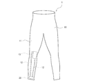
以下、本発明の実施形態について説明するが、まず、一実施形態として下半身に着用されるコンプレッションウェアを例にとり図1及び図2を参酌しつつ説明する。 Hereinafter, embodiments of the present invention will be described. First, as an embodiment, compression wear worn on the lower body will be described as an example with reference to FIGS. 1 and 2.
<被服1>
図1の被服1は、歪みセンサ付き布帛10と、この歪みセンサ13によって検出された検知信号を送信する送信モジュール20とを有している。
<
The
(歪みセンサ付き布帛10)
前記歪みセンサ付き布帛10は、伸縮可能な布帛本体11、この布帛本体11に付設される歪みセンサ13、及びこの歪みセンサ13と前記送信モジュール20とを電気的に接続するための一対の配線部12を備えている。
(Fabric with strain sensor 10)
The fabric with
前記布帛本体11は、糸(糸状体)が編成又は織成されている。この布帛本体11を構成する糸は、伸縮性を有するものが好適に用いられ、この糸が編成されることで布帛本体11が全体的には伸縮可能に設けられていることが好ましい。また、この布帛本体11を構成する糸は、導電性を有さないものが好適に用いられる。
The
前記歪みセンサ13は、布帛本体11に一体的に付設されている。この歪みセンサ13は、例えば被服1において着用者の動作を認識できる部位に配設され、例えば関節に相当する部位に配設され、図示例では膝関節の正面側に配設されている。
The
この歪みセンサ13は、布帛本体11の一方の面(例えば布帛本体11の内面)に貼着されており、これにより歪みセンサ13は布帛本体11に一体的に付設されている。なお、歪みセンサ13を布帛本体11に一体的に付設する手段は、貼着に限られず、例えば布帛本体に歪みセンサを縫着したり、また布帛本体に歪みセンサを積層形成することも適宜採用可能である。
The
また、歪みセンサ13の貼着は、弾性接着剤によってなされていることが好ましい。この弾性接着剤は、硬化後の弾性率が1MPa以上10MPaであることが好ましい。この硬化後の弾性接着剤の弾性率が上記上限を超えると、弾性接着剤が硬化した層によって布帛本体11の伸縮が阻害されるおそれがある。一方、上記弾性率が上記下限未満であると、布帛本体11の伸縮が弾性接着剤からなる層で吸収されてしまい、歪みセンサ13に的確に伝達されないおそれがある。
Moreover, it is preferable that the
この歪みセンサ13は、布帛本体11の伸縮に追従可能に布帛本体11に付設されている。具体的には、歪みセンサ13は伸縮性を有し、伸縮性を有する布帛本体11に一体的に付設されることで、布帛本体11の伸縮に伴って歪みセンサ13が伸縮するよう設けられている。なお、歪みセンサ13を少なくとも両端部分で布帛本体に固定(例えば貼着、縫着等)することで、布帛本体11の伸縮に従って歪みセンサ13が伸縮するよう設けることも可能である。この歪みセンサ13は、伸縮に応じて電気信号(検知信号)を前記配線部12に送信する。この歪みセンサ13としては、カーボンナノチューブ(以下、CNTということがある)を用いたCNT歪みセンサ13が好適に用いられる。このCNT歪みセンサ13は、前記布帛本体11に貼着される基板と、この基板の表面側に設けられるCNT膜と、このCNT繊維の端部にそれぞれ配設される一対の電極と、前記CNT膜を保護する保護部とを主に備える。
The
前記CNT歪みセンサ13の基板は、柔軟性を有する板状体から構成されている。この基板のサイズとしては特に限定されず、例えば厚みが10μm以上5mm以下、幅が1mm以上5cm以下、長さが1cm以上20cm以下とすることができる。
The substrate of the
この基板の材質としては、柔軟性を有する限り特に限定されず、例えば合成樹脂、ゴム、不織布、変形可能な形状又は材質の金属や金属化合物等を挙げることができる。 The material of the substrate is not particularly limited as long as it has flexibility, and examples thereof include synthetic resin, rubber, non-woven fabric, deformable shape or material metal or metal compound, and the like.
上記合成樹脂としては、例えばフェノール樹脂(PF)、エポキシ樹脂(EP)、メラミン樹脂(MF)、尿素樹脂(ユリア樹脂、UF)、不飽和ポリエステル樹脂(UP)、アルキド樹脂、ポリウレタン(PUR)、熱硬化性ポリイミド(PI)、ポリエチレン(PE)、高密度ポリエチレン(HDPE)、中密度ポリエチレン(MDPE)、低密度ポリエチレン(LDPE)、ポリプロピレン(PP)、ポリ塩化ビニル(PVC)、ポリ塩化ビニリデン、ポリスチレン(PS)、ポリ酢酸ビニル(PVAc)、アクリロニトリルブタジエンスチレン樹脂(ABS)、アクリロニトリルスチレン樹脂(AS)、ポリメチルメタアクリル樹脂(PMMA)、ポリアミド(PA)、ポリアセタール(POM)、ポリカーボネート(PC)、変性ポリフェニレンエーテル(m−PPE)、ポリブチレンテレフタレート(PBT)、ポリエチレンテレフタレート(PET)、環状ポリオレフィン(COP)等を挙げることができる。 Examples of the synthetic resin include phenol resin (PF), epoxy resin (EP), melamine resin (MF), urea resin (urea resin, UF), unsaturated polyester resin (UP), alkyd resin, polyurethane (PUR), Thermosetting polyimide (PI), polyethylene (PE), high density polyethylene (HDPE), medium density polyethylene (MDPE), low density polyethylene (LDPE), polypropylene (PP), polyvinyl chloride (PVC), polyvinylidene chloride, Polystyrene (PS), polyvinyl acetate (PVAc), acrylonitrile butadiene styrene resin (ABS), acrylonitrile styrene resin (AS), polymethyl methacrylate resin (PMMA), polyamide (PA), polyacetal (POM), polycarbonate (PC) , Degeneration Polyphenylene ether (m-PPE), polybutylene terephthalate (PBT), polyethylene terephthalate (PET), and cyclic polyolefin (COP) and the like.
上記ゴムとしては、例えば天然ゴム(NR)、ブチルゴム(IIR)、イソプレンゴム(IR)、エチレン・プロピレンゴム(EPDM)、ブタジエンゴム(BR)、ウレタンゴム(U)、スチレン・ブタジエンゴム(SBR)、シリコーンゴム(Q)、クロロプレンゴム(CR)、クロロスルフォン化ポリエチレンゴム(CSM)、アクリロニトリルブタジエンゴム(NBR)、塩素化ポリエチレン(CM)、アクリルゴム(ACM)、エピクロルヒドリンゴム(CO,ECO)、フッ素ゴム(FKM)、PDMS等を挙げることができる。これらのゴムの中でも強度等の点から天然ゴムが好ましい。 Examples of the rubber include natural rubber (NR), butyl rubber (IIR), isoprene rubber (IR), ethylene / propylene rubber (EPDM), butadiene rubber (BR), urethane rubber (U), and styrene / butadiene rubber (SBR). , Silicone rubber (Q), chloroprene rubber (CR), chlorosulfonated polyethylene rubber (CSM), acrylonitrile butadiene rubber (NBR), chlorinated polyethylene (CM), acrylic rubber (ACM), epichlorohydrin rubber (CO, ECO), Fluoro rubber (FKM), PDMS, etc. can be mentioned. Among these rubbers, natural rubber is preferable from the viewpoint of strength.
電極は、特に限定されるものではないが、導電性弾性接着剤の塗工によって形成されている。なお、この電極は銅等の金属等を用いることも可能であり、金属製の電極にあっては形状がメッシュ状であることが好ましい。 The electrode is not particularly limited, but is formed by applying a conductive elastic adhesive. In addition, it is also possible to use metals, such as copper, for this electrode, and when it is a metal electrode, it is preferable that a shape is a mesh form.
CNT膜は、正面視矩形形状を有している。このCNT膜の長手方向の両端部分に前記電極が接続されている。また、カーボンナノチューブ膜は、一方向(一対の電極を結ぶ直線の方向と異なる方向)に配向する複数のCNT繊維を有している。このようにCNT繊維が配向していることで一対の電極が離れる方向へ歪みが加わった場合(CNT膜が伸長した場合)に、CNT繊維同士の接触具合に変化が起こり、歪みセンサ13として抵抗変化を得ることができる。なお、より効率良く歪みを検出するには、好ましくはCNT膜は一対の電極の配設方向(一対の電極を結ぶ直線の方向)と略垂直方向、好ましくは垂直方向にCNT繊維が配向されていると良い。
The CNT film has a rectangular shape in front view. The electrodes are connected to both ends of the CNT film in the longitudinal direction. Further, the carbon nanotube film has a plurality of CNT fibers oriented in one direction (a direction different from the direction of a straight line connecting a pair of electrodes). When the strain is applied in the direction in which the pair of electrodes are separated due to the orientation of the CNT fibers in this manner (when the CNT film is stretched), the contact condition between the CNT fibers changes, and the
各CNT繊維は、複数のCNT単繊維から構成することができる。ここで、CNT単繊維とは、1本の長尺のCNTをいう。また、CNT繊維は、CNT単繊維の端部同士が連結する連結部を有する。CNT単繊維同士は、これらのCNT単繊維の長手方向に連結している。このように、CNT膜において、CNT単繊維同士がその長手方向に連結してなるCNT繊維を用いることで、CNT繊維の配向方向に幅の広いCNT膜を形成することができ、その結果、CNT膜の抵抗値を下げ、かつ、この抵抗値のバラツキも低減することができる。 Each CNT fiber can be composed of a plurality of CNT single fibers. Here, the CNT single fiber means one long CNT. In addition, the CNT fiber has a connection portion where the ends of the CNT single fibers are connected to each other. The CNT single fibers are connected in the longitudinal direction of these CNT single fibers. Thus, in the CNT film, by using the CNT fiber formed by connecting the CNT single fibers in the longitudinal direction, a CNT film having a wide width in the alignment direction of the CNT fiber can be formed. The resistance value of the film can be lowered, and variations in the resistance value can also be reduced.
また、複数のCNT繊維は、網目構造を形成している。具体的には、複数のCNT繊維は連結部等により網目状に連結又は接触している。この際、連結部において、3つ以上のCNT単繊維の端部が結合していてもよいし、連結部のように2つのCNT単繊維の端部と他のCNT単繊維の中間部とが結合していてもよい。複数のCNT繊維がこのような網目構造を形成することで、CNT繊維同士が密接し、CNT膜の抵抗を下げることができる。 The plurality of CNT fibers form a network structure. Specifically, the plurality of CNT fibers are connected or in contact with each other by a connecting portion or the like. At this time, at the connecting portion, the ends of three or more CNT single fibers may be combined, or the ends of two CNT single fibers and an intermediate portion of another CNT single fiber as in the connecting portion. It may be bonded. When a plurality of CNT fibers form such a network structure, the CNT fibers are in close contact with each other, and the resistance of the CNT film can be reduced.
また、この際、上記連結部が主な基点なって近隣のCNT繊維同士が連結又は接触することによって、CNT繊維が両持ち梁構造として機能することができる。CNT繊維同士の連結とは上記連結部等とCNT繊維が電気的に繋がることであり、CNT繊維の連結部ではない部分同士が電気的に繋がった場合も連結に含まれる。CNT繊維同士の接触とは上記連結部等とCNT繊維が触れているが電気的に繋がっていないことであり、CNT繊維の連結部ではない部分同士が触れているが電気的に繋がっていない場合も接触に含まれる。両持ち梁として機能するCNT繊維はバネ定数が大きくなる。そのため、CNT繊維は、この配向方向Bと垂直方向(CNT膜の長手方向)には伸縮しにくい構造となっている。従って、CNT膜がCNT繊維の配向方向と垂直方向(CNT膜の長手方向)に対して剛性が強くなり、そのCNT歪みセンサによれば、CNT膜の長手方向の歪みに対して、敏感に検知することができ、さらにリニアリティを高めることができる。なお、CNT繊維の連結部が主な基点となって、隣り合うCNT繊維間に限らず、何本か飛び越えた場所のCNT繊維と連結又は接触してもよい。このように、複雑な網目状のCNT繊維を有するCNT膜であれば、より抵抗値が低くなり、CNT繊維と垂直な方向に剛性の強い歪みセンサすることができる。 At this time, the CNT fibers can function as a doubly supported beam structure by connecting or contacting neighboring CNT fibers with the connecting portion as a main base point. The connection between the CNT fibers means that the connection part and the CNT fiber are electrically connected, and the case where the parts other than the connection part of the CNT fiber are electrically connected is also included in the connection. The contact between the CNT fibers means that the CNT fibers are in contact with the above-mentioned connecting portions but are not electrically connected, and the non-connected portions of the CNT fibers are in contact with each other but are not electrically connected. Is also included in the contact. A CNT fiber that functions as a doubly supported beam has a large spring constant. Therefore, the CNT fiber has a structure that hardly stretches in the direction perpendicular to the orientation direction B (longitudinal direction of the CNT film). Accordingly, the rigidity of the CNT film becomes stronger in the direction perpendicular to the orientation direction of the CNT fiber (longitudinal direction of the CNT film), and the CNT strain sensor detects sensitively to the strain in the longitudinal direction of the CNT film. And linearity can be further improved. In addition, the connection part of a CNT fiber becomes a main base point, and it may connect or contact with the CNT fiber of the place which not only between adjacent CNT fibers but jumped some. As described above, if the CNT film has a complex network-like CNT fiber, the resistance value is further reduced, and a strain sensor having strong rigidity in a direction perpendicular to the CNT fiber can be obtained.
なお、CNT繊維は、各CNT単繊維が実質的にCNT繊維の長手方向に配向され、撚糸されていない状態のものである。このようなCNT繊維を用いることで、CNT膜の均一性を高め、歪みセンサとしてのリニアリティを高めることができる。 The CNT fiber is in a state where each CNT single fiber is substantially oriented in the longitudinal direction of the CNT fiber and is not twisted. By using such a CNT fiber, the uniformity of the CNT film can be enhanced and the linearity as a strain sensor can be enhanced.
なお、上記連結部において、各CNT単繊維同士は分子間力により結合している。このため、複数のCNT繊維が連結部により網目状に連結した場合においても、連結部の存在による抵抗の上昇が抑えられる。 In the connection part, the CNT single fibers are bonded together by intermolecular force. For this reason, even when a plurality of CNT fibers are connected in a mesh shape by the connecting portion, an increase in resistance due to the presence of the connecting portion is suppressed.
CNT膜のサイズについては特に限定されるものではないが、例えばCNT膜の幅(短手方向の長さ)は、好ましくは1mm以上10cm以下、より好ましくは1cm以上5cm以下の範囲内とすることができる。CNT膜の幅を比較的大きくすることで、CNT膜の抵抗値を下げ、かつ、この抵抗値のバラツキも低減することができる。 The size of the CNT film is not particularly limited. For example, the width (length in the short direction) of the CNT film is preferably in the range of 1 mm to 10 cm, more preferably 1 cm to 5 cm. Can do. By making the width of the CNT film relatively large, the resistance value of the CNT film can be lowered, and variations in the resistance value can also be reduced.
CNT膜の厚みとしては、特に限定されないが、例えば、CNT膜の平均厚みの下限としては、1μmが好ましく、10μmがさらに好ましい。一方、CNT膜の平均厚みの上限としては、5mmが好ましく、1mmがさらに好ましい。CNT膜の平均厚みが上記下限未満の場合は、このような薄膜の形成が困難になるおそれや、抵抗が上昇しすぎるおそれがある。逆に、CNT膜の平均厚みが上記上限を超える場合は、伸縮性が低下するおそれがあるとともに伸縮に対する感受性が低下するおそれがある。 Although it does not specifically limit as thickness of a CNT film | membrane, For example, as a minimum of the average thickness of a CNT film | membrane, 1 micrometer is preferable and 10 micrometers is more preferable. On the other hand, the upper limit of the average thickness of the CNT film is preferably 5 mm, and more preferably 1 mm. When the average thickness of the CNT film is less than the above lower limit, it may be difficult to form such a thin film, or the resistance may increase excessively. On the other hand, when the average thickness of the CNT film exceeds the above upper limit, the stretchability may be lowered and the sensitivity to the stretch may be lowered.
なお、CNT膜は、CNT繊維を平面状に略平行に配置した単層構造からなってもよいし、多層構造からなってもよい。但し、ある程度の導電性を確保するためには、多層構造とすることが好ましい。 Note that the CNT film may have a single-layer structure in which CNT fibers are arranged substantially in parallel in a planar shape, or may have a multilayer structure. However, in order to ensure a certain degree of conductivity, a multilayer structure is preferable.
CNT繊維としては、単層のシングルウォールナノチューブ(SWNT)や、多層のマルチウォールナノチューブ(MWNT)のいずれも用いることができるが、導電性及び熱容量等の点から、MWNTが好ましく、直径1.5nm以上100nm以下のMWNTがさらに好ましい。 As the CNT fiber, either single-walled single-wall nanotubes (SWNT) or multi-walled multi-wall nanotubes (MWNT) can be used, but MWNT is preferable from the viewpoint of conductivity and heat capacity, and the diameter is 1.5 nm. More preferably, the MWNT is 100 nm or less.
上記配線部12は、布帛本体11に縫い付けられた導電性を有する糸(糸状体)から構成され、このように布帛本体11に縫い付けられることで配線部12は布帛本体11に一体的に設けられる。
The
この配線部12を構成する糸は、導電性を有する導電糸が用いられる。この導電糸としては、鉄等の金属製の導電糸を用いることができ、この金属製の導電糸としてはステンレス糸が好適に用いられる。ステンレス糸によれば、電気抵抗が小さく、また当該被服1を洗濯した場合にあっても電気抵抗の変化が比較的少ない利点を有する。なお、この配線部12を構成する糸としては、絶縁性の糸に導電性材料を塗工した糸や、導電性材料を混紡して形成した糸を用いることも可能である。
As the yarn constituting the
この配線部12を構成する糸は、10cmあたりの電気抵抗が100Ω未満であることが好ましく、50Ω未満であることがさらに好ましい。これにより、配線部12の電気抵抗を小さくすることができ、歪みセンサ13からの検知信号を的確に送信モジュール20に伝達することができる。なお、「10cmあたりの抵抗値」とは、5Vの電圧をかけたときの糸10cm間の抵抗値であり、汎用のテスターを用いて測定することができる。
The yarn constituting the
配線部12は、伸縮性を有し、布帛本体11の伸縮に追従して変形するよう設けられている。具体的には、配線部12は、導電性を有する糸を伸縮縫いすることによって形成されている。なお、伸縮縫いとは、「JIS B 9003」で規定されるように、「伸縮性のある布地を縫ったとき、布地の伸び縮みによって、縫い目が切れたり、緩んだりしないように縫うこと」を意味する。具体的には、本実施形態の配線部12は、図2に示すように、カバーステッチ(片面飾り縫い)によって形成されている。
The
(送信モジュール20)
前記送信モジュール20は、着用者の邪魔にならない箇所に配設され、例えば裾部に配設されている。なお、その他、ポケットを有する被服1の場合には、このポケットに送信モジュール20を配設する等、形成場所は特に限定されない。また、送信モジュール20を布帛本体11に固着することも可能であるが、送信モジュール20が当該歪みセンサ付き布帛10に着脱可能に付設されていることが好ましい。なお、この着脱可能に付設する手段は特に限定されないが、例えば面ファスナー等を採用可能である。上記のように送信モジュール20を布帛本体11に着脱可能に設けることで、送信モジュール20を取り外した状態で当該被服1の布帛本体11を容易且つ確実に洗濯することが可能となる。
(Transmission module 20)
The
送信モジュール20は、配線部12を介して受け取った検知信号を、外部機器に無線通信によって送信可能な送信手段を有している。なお、当該被服1にあっては、送信モジュール20が配線部12を介して受け取った検知信号を蓄積する記憶手段を有する構成や、送信モジュール20が上記検知信号の判別を行う処理手段を有する構成を採用することも可能である。
The
<被服1の製造方法>
当該被服1の製造方法は特に限定されるものではないが、以下の方法によって製造することができる。
<Method of
Although the manufacturing method of the said
つまり、当該被服1の製造方法は、糸を編成して布帛本体11を形成する工程、この布帛本体11を衣服の状態に縫製する工程、この縫製工程後の布帛本体11に配線部12を形成する工程、縫製工程後の布帛本体11に歪みセンサ13を付設する工程、及び送信モジュール20を付設する工程を有する。なお、配線部形成工程と歪みセンサ付設工程との前後は特に限定されず、配線部12を先に形成し歪みセンサ13を後に付設することも、また歪みセンサ13を先に付設し配線部12を後に形成することも、さらには配線部12の形成に際して歪みセンサ13を縫い付けることも適宜設計変更可能な事項である。また、配線部12形成工程及び/又は歪みセンサ13付設工程を行った後に、布帛本体11を縫製する縫製工程を行うことも可能である。
That is, the manufacturing method of the
<利点>
上記構成からなる被服1にあっては、着用者の動作によって歪みセンサ13が伸縮されると、歪みセンサ13が配線部12を介して検知信号を送信モジュール20に送信し、この検知信号を受け取った送信モジュール20は外部機器に検知信号を送信する。このため、外部機器において、検知信号を判別することによって、着用者の動作を検知することができる。
<Advantages>
In the
特に、当該被服1にあっては、配線部12は伸縮性を有し、布帛本体11の伸縮に追従して変形するので、配線部12が布帛本体11の伸縮を妨げず、着用者の動作の邪魔になりにくい。また、配線部12が伸縮性を有するので、当該被服1の着脱を困難ならしめることがない。
In particular, in the
さらに、配線部12は布帛本体11に一体的に取付けられているので、着用者の動作の邪魔にならず、また従来の被服1のような配線同士が絡まり合うことがないので、配線部12が断線しにくい。
Furthermore, since the
また、歪みセンサ13は弾性接着剤によって布帛本体11に貼着されているので、着用者の動作によって的確に布帛本体11が伸縮することができる。
In addition, since the
<その他の実施形態>
本実施形態は上記構成からなり、上述の利点を奏するものであったが、本発明は上記実施形態に限定されるものではなく、本発明の意図する範囲内において適宜設計変更可能である。
<Other embodiments>
Although the present embodiment has the above-described configuration and has the above-described advantages, the present invention is not limited to the above-described embodiment, and the design can be appropriately changed within the intended scope of the present invention.
つまり、上記実施形態においては、配線部12に伸縮性を持たせるために伸縮縫いによって配線部12を形成するものについて説明したが、本発明はこれに限定されるものではない。例えば、配線部として、布帛本体111の編成又は織成に際して導電性を有さない糸状体とともに導電性を有する糸状体を編成又は織成することで形成された配線部112を採用可能である。具体的には、図3に示すように、布帛本体111をニット編みによって編成し、このニット編みの一つ又は複数のコースを導電性を有する糸で編成することで、この導電性を有する糸で編成されたコースの部分によって配線部112を形成することも可能である。
That is, in the said embodiment, although what formed the
また、配線部として、布帛本体の一方の面に付設された導電性を有する帯状部材から構成することも可能である。具体的には、例えば導電性を有する糸を編成して伸縮性及び導電性を有する紐(帯状部材)を形成し、この帯状部材を布帛本体に付設することも可能である。なお、この付設方法としては、弾性接着剤による貼着や、伸縮性を損なわないように縫い付ける等の方法を採用することができる。また、この帯状部材は、布帛本体の外面側に配設することも、内面側に配設することも適宜設計変更可能である。 Moreover, it is also possible to comprise from the strip | belt-shaped member which has the electroconductivity attached to one surface of the fabric main body as a wiring part. Specifically, for example, a conductive yarn can be knitted to form a stretchable and conductive string (band member), and this band member can be attached to the fabric body. In addition, as this attachment method, methods such as sticking with an elastic adhesive or sewing so as not to impair stretchability can be employed. In addition, the design of the strip-shaped member can be appropriately changed to be disposed on the outer surface side of the fabric body or on the inner surface side.
また、当該歪みセンサ付き布帛において、配線部12を上記実施形態のように導電性を有する糸を縫い付けて形成する場合にあっても、上記のような伸縮編みによって形成するものに限定されるものではない。具体的には、例えば図4に示すように布帛本体211に導電性及び伸縮性を有する糸をロックステッチによって縫いつけて、この糸によって伸縮性を有する配線部212を形成することも可能である。
Further, in the fabric with a strain sensor, even when the
さらに、当該歪みセンサ付き布帛において、上記実施形態のように伸縮編みによって配線部12を形成する場合にあっても、カバーステッチによって形成するものに限定されるものではなく、その他の縫い方によって配線部を形成することも可能である。具体的には、図5に示すようなチェーンステッチによって布帛本体311に糸を縫い付けることで配線部312を形成することも可能である。
Further, in the fabric with the strain sensor, even when the
なお、当該歪みセンサ付き布帛にあっては、上記配線部は、一つの種類のみを採用するものに限られず、上述において説明した複数種類の配線部を組み合わせて用いることも適宜設計変更可能な事項である。 In addition, in the fabric with the strain sensor, the wiring part is not limited to adopting only one type, and it is also possible to change the design as appropriate by combining a plurality of types of wiring parts described above. It is.
また、上記実施形態においては、被服1として、下半身に着用されるコンプレッションウェアを例にとり説明したが、本発明はこれに限定されるものではなく、例えばその他のスポーツウェアを採用することも可能である。また、着用される部位も、下半身に限定されるものでなく、上半身であっても良く、また手に着用される手袋、関節部位に着用される関節サポータを採用することも可能である。
Moreover, in the said embodiment, although demonstrated taking the example of the compression wear worn by the lower body as the
さらに、上記実施形態において、例えばスポーツウェア等の衣類の裾部に、図6のように導電体からなる端子21を配設したものも採用可能である。この図6の被服1にあっては、送信モジュール(図示省略)の端子と上記端子21を接触させ、送信モジュールを着脱可能に布帛本体10に取付けることができる。上記端子21と送信モジュールの端子との固定方法は、磁力を用いてもよいし、粘着剤を用いてもよい。また、送信モジュールを当該衣服1の裾部と一緒にバンド等の巻回部材で巻回することで送信モジュールを固定してもよい。この場合、着用者の足首付近がバンド固定されることになり、着用者の邪魔にならず、送信モジュールの着脱も可能となる。
Furthermore, in the said embodiment, what arrange | positioned the terminal 21 which consists of a conductor like FIG. In the
本実施形態においては、歪みセンサ付き布帛10として編物を例にとり説明したが、本発明はこれに限定されるものではなく、経糸と緯糸とが織成されて構成する織物を採用することも可能であり、さらには不織布を採用することも可能である。
In the present embodiment, the knitted fabric has been described as an example of the
さらに、上記実施形態では、歪みセンサとしてCNT歪みセンサを用いたものについて説明したが、本発明は必ずしもこれに限定されるものではなく、例えば静電容量型の歪みセンサを用いることも可能である。 Furthermore, in the above embodiment, the CNT strain sensor is used as the strain sensor. However, the present invention is not necessarily limited to this, and for example, a capacitive strain sensor can be used. .
また、上記実施形態は、歪みセンサの付設方法として弾性接着剤を用いたものについて説明したが、本発明はこれに限定されるものではなく、その他の付設方法も適宜採用可能である。例えば歪みセンサをその伸縮性を損なわないように縫い付けることで布帛本体に付設することも可能である。また、歪みセンサと布帛本体とを面ファスナー等によって貼着することで、布帛本体に着脱可能に歪みセンサを付設することも可能である。 Moreover, although the said embodiment demonstrated what used the elastic adhesive as an attachment method of a strain sensor, this invention is not limited to this, Other attachment methods are also employable suitably. For example, the strain sensor can be attached to the fabric body by sewing so as not to impair the stretchability. In addition, by attaching the strain sensor and the fabric body with a hook-and-loop fastener or the like, the strain sensor can be detachably attached to the fabric body.
以上説明したように、本発明の歪みセンサ付き布帛は、布帛本体を伸縮させる動作に対して配線が邪魔となりにくく、配線が断線しにくいので、例えばコンプレッションウェア等のスポーツウェアに好適に用いることができる。 As described above, the fabric with a strain sensor according to the present invention is preferably used for sportswear such as compression wear, for example, because the wiring is not obstructive to the operation of expanding and contracting the fabric body and the wiring is not easily broken. it can.
1 被服
10 歪みセンサ付き布帛
11 布帛本体
12 配線部
13 歪みセンサ
20 送信モジュール
21 端子
111、211、311 布帛本体
112、212、312 配線部
DESCRIPTION OF
Claims (5)
前記歪みセンサに電気的に接続されるとともに前記布帛本体に一体的に設けられ且つ布帛本体の伸縮に追従して変形する配線部を備え、
前記歪みセンサが、柔軟性を有する板状体から構成される基板と、この基板の一方の面側に設けられるCNT膜とを有し、
前記歪みセンサが、伸縮性を有し、前記布帛本体に一体的に付設され、前記布帛本体の伸縮に伴って歪みセンサが伸縮するよう設けられ、
前記歪みセンサは、前記布帛本体に弾性接着剤によって貼着され、この弾性接着剤の硬化後の弾性率が1MPa以上10MPa以下であることを特徴とする歪みセンサ付き布帛。 A fabric with a strain sensor, comprising a fabric body that can be stretched and a strain sensor attached to the fabric body and capable of following the stretch of the fabric body,
A wiring portion that is electrically connected to the strain sensor and integrally provided in the fabric body and deforms following the expansion and contraction of the fabric body;
The strain sensors possess a substrate composed of a plate-like body having flexibility, and a CNT film provided on one surface of the substrate,
The strain sensor has stretchability and is integrally attached to the fabric body, and is provided so that the strain sensor expands and contracts as the fabric body stretches,
The strain sensor, the is adhered to the fabric body by an elastic adhesive, the strain sensor with fabric elastic modulus after curing of the elastic adhesive is characterized der Rukoto least 10MPa or less 1 MPa.
前記配線部が、前記布帛本体の編成又は織成に際して前記導電性を有さない糸状体とともに導電性を有する糸状体を編成又は織成することで形成されている請求項1に記載の歪みセンサ付き布帛。 The fabric body is made of a fabric formed by knitting or weaving a thread-like body having no conductivity,
The strain sensor according to claim 1, wherein the wiring portion is formed by knitting or weaving a conductive thread-like body together with the non-conductive thread-like body during knitting or weaving of the fabric body. Attached fabric.
A garment comprising the fabric with a strain sensor according to any one of claims 1 to 4.
Priority Applications (1)
| Application Number | Priority Date | Filing Date | Title |
|---|---|---|---|
| JP2012167736A JP6019890B2 (en) | 2012-07-27 | 2012-07-27 | Fabric and clothing with strain sensor |
Applications Claiming Priority (1)
| Application Number | Priority Date | Filing Date | Title |
|---|---|---|---|
| JP2012167736A JP6019890B2 (en) | 2012-07-27 | 2012-07-27 | Fabric and clothing with strain sensor |
Publications (3)
| Publication Number | Publication Date |
|---|---|
| JP2014025180A JP2014025180A (en) | 2014-02-06 |
| JP2014025180A5 JP2014025180A5 (en) | 2015-11-26 |
| JP6019890B2 true JP6019890B2 (en) | 2016-11-02 |
Family
ID=50199075
Family Applications (1)
| Application Number | Title | Priority Date | Filing Date |
|---|---|---|---|
| JP2012167736A Active JP6019890B2 (en) | 2012-07-27 | 2012-07-27 | Fabric and clothing with strain sensor |
Country Status (1)
| Country | Link |
|---|---|
| JP (1) | JP6019890B2 (en) |
Families Citing this family (20)
| Publication number | Priority date | Publication date | Assignee | Title |
|---|---|---|---|---|
| JP6549377B2 (en) * | 2015-01-09 | 2019-07-24 | ヤマハ株式会社 | Telescopic wiring |
| JP6488131B2 (en) * | 2015-01-09 | 2019-03-20 | ヤマハ株式会社 | Foot motion detection supporter |
| JP6325482B2 (en) * | 2015-04-06 | 2018-05-16 | バンドー化学株式会社 | Capacitance type sensor sheet and sensor device |
| US10398377B2 (en) | 2015-09-04 | 2019-09-03 | Japan Science And Technology Agency | Connector substrate, sensor system, and wearable sensor system |
| JP6912089B2 (en) | 2015-10-16 | 2021-07-28 | 国立研究開発法人科学技術振興機構 | Stress relaxation boards and textile devices |
| WO2017065272A1 (en) | 2015-10-16 | 2017-04-20 | 国立研究開発法人科学技術振興機構 | Wiring film, device transfer sheet, and textile-type device |
| JP6745495B2 (en) * | 2016-01-12 | 2020-08-26 | 学校法人北里研究所 | Shape estimation device, scanning device, motion detection device, shape estimation method, scanning method, motion detection method, program |
| JP6673582B2 (en) * | 2016-01-12 | 2020-03-25 | 日本電気株式会社 | Motion measuring device, method, and program |
| JP6960725B2 (en) * | 2016-07-29 | 2021-11-05 | グンゼ株式会社 | Posture detection clothing |
| WO2018116424A1 (en) * | 2016-12-21 | 2018-06-28 | 株式会社Xenoma | Wearable device |
| KR101895694B1 (en) | 2016-12-22 | 2018-10-24 | 연세대학교 산학협력단 | Textile motion sensor, a method of fabricating the same, and clothing system including the same |
| JP2020064883A (en) * | 2017-01-11 | 2020-04-23 | 帝人株式会社 | Sensor system, garment, and garment system |
| JP6848458B2 (en) * | 2017-01-16 | 2021-03-24 | ヤマハ株式会社 | Sensor unit |
| JP6903981B2 (en) * | 2017-03-23 | 2021-07-14 | セイコーエプソン株式会社 | Detection device |
| JP2021004820A (en) * | 2019-06-27 | 2021-01-14 | 地方独立行政法人東京都立産業技術研究センター | Contact pressure sensor and contact pressure measurement system |
| JP7297611B2 (en) * | 2019-09-10 | 2023-06-26 | 日本航空電子工業株式会社 | electrical relay material |
| DE102020106559A1 (en) | 2020-03-11 | 2021-09-16 | Ntt New Textile Technologies Gmbh | Textile carrier material |
| DE102021112839B3 (en) | 2021-05-18 | 2022-06-09 | Ntt New Textile Technologies Gmbh | Method of making a connection between an electrode and an electrical conductor |
| CN114353657B (en) * | 2022-02-08 | 2023-08-15 | 武汉纺织大学 | Preparation method of fabric-based negative resistance strain sensor |
| DE102022110523A1 (en) | 2022-04-29 | 2023-11-02 | Ntt New Textile Technologies Gmbh | Electrode for a piece of clothing, a belt or a bandage |
Family Cites Families (8)
| Publication number | Priority date | Publication date | Assignee | Title |
|---|---|---|---|---|
| JPH0881959A (en) * | 1994-09-06 | 1996-03-26 | Mitsui Sekika Sanshi Kk | Material of construction of which strain gage is bonded and bonding method of material of construction |
| GB0004496D0 (en) * | 2000-02-26 | 2000-04-19 | Koninkl Philips Electronics Nv | Sliding switch |
| CN1245780C (en) * | 2001-04-10 | 2006-03-15 | 皇家菲利浦电子有限公司 | Combination quick release buckle and electrical connector |
| JP2005322052A (en) * | 2004-05-10 | 2005-11-17 | Hokkaido Technology Licence Office Co Ltd | Ubiquitous system, device connection method, electroconductive cloth, electroconductive clothes and electroconductive wall |
| JP5432513B2 (en) * | 2008-12-18 | 2014-03-05 | 旭化成せんい株式会社 | Biological signal measuring device |
| JP5397896B2 (en) * | 2009-08-25 | 2014-01-22 | 独立行政法人産業技術総合研究所 | EXTENSION DEVICE, EXTENSION DRIVE DEVICE, AND CNT FILM STRUCTURE USING CARBON NANOTUBE |
| JP2011209255A (en) * | 2010-03-30 | 2011-10-20 | Resuka:Kk | Clothes pressure sensor |
| JP2012025309A (en) * | 2010-07-26 | 2012-02-09 | Yazaki Corp | Onboard circuit |
-
2012
- 2012-07-27 JP JP2012167736A patent/JP6019890B2/en active Active
Also Published As
| Publication number | Publication date |
|---|---|
| JP2014025180A (en) | 2014-02-06 |
Similar Documents
| Publication | Publication Date | Title |
|---|---|---|
| JP6019890B2 (en) | Fabric and clothing with strain sensor | |
| JP6341268B2 (en) | Gloves with strain sensor | |
| CN109073353B (en) | Strain sensor unit | |
| JP6264825B2 (en) | Fabric and clothing with strain sensor | |
| JP5668966B2 (en) | Conductive fabric and touch sensor device using conductive fabric | |
| WO2017104596A1 (en) | Clothing | |
| US20190072440A1 (en) | Fibre-based sensor for yarn | |
| JP6470049B2 (en) | Yarn-like strain sensor element and fabric-like strain sensor element | |
| TWI822887B (en) | Cloth material with wiring and electrode | |
| JP2017075847A (en) | Movement detection device | |
| JP7068569B2 (en) | Tension sensor | |
| WO2018047718A1 (en) | Anisotropic strain sensor sheet and clothing | |
| JP6848458B2 (en) | Sensor unit | |
| JP2016129121A (en) | Elastic wiring | |
| JP6561640B2 (en) | Strain sensor element | |
| JP6822855B2 (en) | Telescopic wiring and manufacturing method of telescopic wiring | |
| JP2016176874A (en) | Strain sensor element | |
| WO2017119197A1 (en) | Distortion sensor element | |
| JP2017211215A (en) | Strain sensor unit and strain measurement kit | |
| JP2018021270A (en) | Human body motion detecting wear | |
| JP2017164296A (en) | Action detection device | |
| JP6678927B2 (en) | Conductive harness, conductive harness structure and conductive harness mounting structure | |
| JP2017211214A (en) | Strain sensor and strain sensor unit | |
| KR20180103482A (en) | Intergrated sensor | |
| KR20180102970A (en) | Load sensor |
Legal Events
| Date | Code | Title | Description |
|---|---|---|---|
| A621 | Written request for application examination |
Free format text: JAPANESE INTERMEDIATE CODE: A621 Effective date: 20150520 |
|
| A521 | Written amendment |
Free format text: JAPANESE INTERMEDIATE CODE: A523 Effective date: 20151007 |
|
| A977 | Report on retrieval |
Free format text: JAPANESE INTERMEDIATE CODE: A971007 Effective date: 20160224 |
|
| A131 | Notification of reasons for refusal |
Free format text: JAPANESE INTERMEDIATE CODE: A131 Effective date: 20160301 |
|
| A521 | Written amendment |
Free format text: JAPANESE INTERMEDIATE CODE: A523 Effective date: 20160425 |
|
| TRDD | Decision of grant or rejection written | ||
| A01 | Written decision to grant a patent or to grant a registration (utility model) |
Free format text: JAPANESE INTERMEDIATE CODE: A01 Effective date: 20160906 |
|
| A61 | First payment of annual fees (during grant procedure) |
Free format text: JAPANESE INTERMEDIATE CODE: A61 Effective date: 20160919 |
|
| R151 | Written notification of patent or utility model registration |
Ref document number: 6019890 Country of ref document: JP Free format text: JAPANESE INTERMEDIATE CODE: R151 |