EP3561881A1 - Testing of a photovoltaic panel - Google Patents
Testing of a photovoltaic panel Download PDFInfo
- Publication number
- EP3561881A1 EP3561881A1 EP19181247.8A EP19181247A EP3561881A1 EP 3561881 A1 EP3561881 A1 EP 3561881A1 EP 19181247 A EP19181247 A EP 19181247A EP 3561881 A1 EP3561881 A1 EP 3561881A1
- Authority
- EP
- European Patent Office
- Prior art keywords
- converter
- electronic module
- photovoltaic panel
- switch
- bypass
- Prior art date
- Legal status (The legal status is an assumption and is not a legal conclusion. Google has not performed a legal analysis and makes no representation as to the accuracy of the status listed.)
- Pending
Links
- 238000012360 testing method Methods 0.000 title abstract description 49
- 238000000034 method Methods 0.000 claims abstract description 32
- 239000007787 solid Substances 0.000 claims description 13
- 238000006243 chemical reaction Methods 0.000 claims description 9
- 238000004891 communication Methods 0.000 claims description 4
- 230000007257 malfunction Effects 0.000 claims description 3
- 230000003213 activating effect Effects 0.000 abstract description 5
- 230000005672 electromagnetic field Effects 0.000 abstract description 3
- 238000010998 test method Methods 0.000 abstract 1
- 235000014676 Phragmites communis Nutrition 0.000 description 18
- 238000010248 power generation Methods 0.000 description 6
- 238000005259 measurement Methods 0.000 description 5
- XUIMIQQOPSSXEZ-UHFFFAOYSA-N Silicon Chemical compound [Si] XUIMIQQOPSSXEZ-UHFFFAOYSA-N 0.000 description 3
- 238000007664 blowing Methods 0.000 description 3
- 229910052710 silicon Inorganic materials 0.000 description 3
- 239000010703 silicon Substances 0.000 description 3
- 230000000694 effects Effects 0.000 description 2
- 238000003306 harvesting Methods 0.000 description 2
- 230000007246 mechanism Effects 0.000 description 2
- 230000005855 radiation Effects 0.000 description 2
- 230000007420 reactivation Effects 0.000 description 2
- 238000001228 spectrum Methods 0.000 description 2
- 239000004593 Epoxy Substances 0.000 description 1
- 239000000853 adhesive Substances 0.000 description 1
- 230000001070 adhesive effect Effects 0.000 description 1
- 230000009286 beneficial effect Effects 0.000 description 1
- 239000013590 bulk material Substances 0.000 description 1
- 230000003750 conditioning effect Effects 0.000 description 1
- 230000009849 deactivation Effects 0.000 description 1
- 238000001514 detection method Methods 0.000 description 1
- 230000010354 integration Effects 0.000 description 1
- 239000000463 material Substances 0.000 description 1
- 238000012986 modification Methods 0.000 description 1
- 230000004048 modification Effects 0.000 description 1
- 238000012544 monitoring process Methods 0.000 description 1
- 239000004848 polyfunctional curative Substances 0.000 description 1
- 229920001296 polysiloxane Polymers 0.000 description 1
- 230000002265 prevention Effects 0.000 description 1
- 239000011347 resin Substances 0.000 description 1
- 229920005989 resin Polymers 0.000 description 1
- 239000004065 semiconductor Substances 0.000 description 1
- 238000012956 testing procedure Methods 0.000 description 1
- 229920001187 thermosetting polymer Polymers 0.000 description 1
- 239000010409 thin film Substances 0.000 description 1
Images


Classifications
-
- H—ELECTRICITY
- H02—GENERATION; CONVERSION OR DISTRIBUTION OF ELECTRIC POWER
- H02S—GENERATION OF ELECTRIC POWER BY CONVERSION OF INFRARED RADIATION, VISIBLE LIGHT OR ULTRAVIOLET LIGHT, e.g. USING PHOTOVOLTAIC [PV] MODULES
- H02S50/00—Monitoring or testing of PV systems, e.g. load balancing or fault identification
- H02S50/10—Testing of PV devices, e.g. of PV modules or single PV cells
-
- Y—GENERAL TAGGING OF NEW TECHNOLOGICAL DEVELOPMENTS; GENERAL TAGGING OF CROSS-SECTIONAL TECHNOLOGIES SPANNING OVER SEVERAL SECTIONS OF THE IPC; TECHNICAL SUBJECTS COVERED BY FORMER USPC CROSS-REFERENCE ART COLLECTIONS [XRACs] AND DIGESTS
- Y02—TECHNOLOGIES OR APPLICATIONS FOR MITIGATION OR ADAPTATION AGAINST CLIMATE CHANGE
- Y02E—REDUCTION OF GREENHOUSE GAS [GHG] EMISSIONS, RELATED TO ENERGY GENERATION, TRANSMISSION OR DISTRIBUTION
- Y02E10/00—Energy generation through renewable energy sources
- Y02E10/50—Photovoltaic [PV] energy
Definitions
- the present invention relates to production testing of photovoltaic panels, and more specifically to testing of photovoltaic panels which include integrated circuitry.
- the number "1.5" indicates that the length of the path of light through the atmosphere is 1.5 times that of the shorter path when the sun is directly overhead.
- Flash tester includes a flash lamp 16, placed inside a closed lightproof cabin 19 which is painted black inside. Alternatively, black curtains minimize the intensity of reflections towards photovoltaic panel 10 from the interior surfaces of the cabin.
- the homogeneity of irradiance over area of photovoltaic panel 10 is measured by placing an irradiance sensor in various positions of the measurement plane.
- a flash tester 17 is connected to the output of photovoltaic panel 10.
- the measurement procedure starts with a flash test of a reference photovoltaic panel.
- the short circuit current is measured during an irradiance corresponding to AM1.5G.
- the reference photovoltaic panel is then exchanged for the test photovoltaic panel.
- the irradiance sensor triggers a current-voltage (IV) measurement procedure at the same irradiance as during the measurement of the reference photovoltaic panel.
- IV current-voltage
- photovoltaic panels are typically connected together in series to form strings and the strings are optionally connected in parallel.
- the combined outputs of the connected photovoltaic panels are typically input to an inverter which converts the generated direct current voltage to alternating current of the grid.
- photovoltaic panels have been designed or proposed with integrated circuitry.
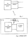
- FIG. 1 illustrates schematically a photovoltaic system 14 with a circuit or electronic module 12 integrated with a photovoltaic panel 10.
- the term "electronic module” as used herein refers to electronic circuitry integrated at the output of the photovoltaic panel.
- the "electronic module” itself may be of the prior art or not of the prior art.
- a representative reference Cascade DC-DC Converter Connection of Photovoltaic Modules, G.R. Walker and P.C. Sernia, Power Electronics Specialists Conference, 2002. (PESC02), Vol. 1 IEEE, Cairns, Australia, pp. 24-29 proposes use of DC-DC converters integrated with the photovoltaic panels.
- the DC-DC converter integrated with the photovoltaic panel is an example of an “electronic module”.
- Other examples of “electronic modules” include, but are not limited to, DC-AC inverters and other power conditioning electronics, as well as sensing and monitoring electronics.
- the “electronic module” herein may have electrical functionality, for instance for improving the electrical conversion efficiency of photovoltaic system 14.
- electronic module as used herein may have another functionality unrelated to electrical performance.
- the function of electronic module 12 is to protect photovoltaic system 12 from theft.
- photovoltaic panel includes any of: one or more solar cells, cells of multiple semiconductor junctions, solar cells connected in different ways (e.g. serial, parallel, serial/parallel), of thin film and/or bulk material, and/or of different materials.
- a method for flash testing a photovoltaic panel connected to an electronic module The electronic module has at least one input attached to the photovoltaic panel and at least one power output.
- the method of flash testing the photovoltaic panel begins by activating a bypass of the electronic module.
- the bypass is activated by applying (preferably externally)a magnetic field or an electromagnetic field,
- the bypass provides a low impedance path between the input and output of the electronic module.
- the electronic module is typically permanently attached to the photovoltaic panel,
- the electronic module optionally performs DC to DC conversion or DC to AC conversion.
- the electronic module optionally performs maximum power point tracking at either the input or the output of the electronic module.
- the bypass circuit may include a reed switch, or a reed relay switch, a solid state switch or a fuse.
- the bypass of the electronic module is typically de-activated, by for instance communicating with the electronic module.
- the bypass may be permanently deactivated, or have an option for re-activation. Re-activation may be beneficial in such scenarios as electronics malfunction (such as disconnect), in which case re-activating the bypass will allow for connection of the photovoltaic panel directly to the output and continued power harvesting.
- a device for flash testing a photovoltaic panel connected to an electronic module.
- the electronic module has at least one input attached to the photovoltaic panel and at least one power output.
- a bypass provides a low impedance path between the input and output of the electronic module.
- the bypass includes a switch between the input and output of the electronic module.
- the switch may be a magnetically activated reed switch, an electromagnetically activated reed relay or a solid state switch.
- the electronic module may be, but is not limited to, a DC to DC converter, a DC to AC converter, or a maximum power point tracking module.
- the bypass includes a fuse and a parallel-connected switch.
- the parallel-connected switch is disposed between and connected in parallel with the photovoltaic panel and the electronic module.
- a power supply unit is connected across the output of the electronic module.
- the parallel-connected switch is closed to provide a low impedance path across the fuse to blow the fuse.
- the parallel-connected switch includes a silicon controlled rectifier, reed switch, solid state switch, or reed relay.
- a power supply is connected directly across said fuse and the current flow of the power supply de-activates the bypass by blowing of the fuse.
- the bypass may include a solid state switch. The bypass is deactivated either permanently (for instance in the case of a blown fuse) or the bypass may be reactivated as required (in the case of a switch.
- a device for flash testing a photovoltaic panel connected to an electronic module The electronic module has at least one input attached to the photovoltaic panel and at least one power output.
- a bypass applied to the electronic module has two single pole double throw (SPDT) switches and a single pole single throw (SPST) switch.
- the output node of the photovoltaic panel is connected to the first SPDT switch common.
- the first output node of the first SPDT is connected to the input node of the electronic module.
- the second output node of the first SPDT switch is connected to the input node of the SPST switch.
- the output node of the SPST switch is connected to a first input node of a second SPDT switch.
- the output node of the electronic module is connected to the second input node of the second SPDT switch.
- the output node of the second SPDT switch is connected to enclosure output which may be connected to the flash tester.
- FIG. 1 illustrates electrical power generation system 14, including photovoltaic panel 10 connected to electronic module 12.
- electronic module 12 is "permanently attached” to photovoltaic panel 10.
- electronic module is integrated with photovoltaic panel 10 but is not “permanently attached” to photovoltaic panel 10.
- the term "permanently attached” as used herein refers to a method or device for attachment such that physical removal or attempt thereof, e.g. of electronic module 12 from photovoltaic panel 10, would result in damage, e.g. to electronic module 12 and/or panel 10. Any mechanism known in the art for "permanently attaching" may be applied in different embodiments of the present invention.
- thermoset adhesive e.g. epoxy based resin, and hardener.
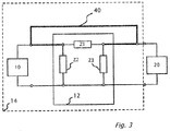
- Electronic module 12 connects photovoltaic panel 10 and test module 20.
- Impedance Z1 is the series equivalent impedance of electronic module 12.
- Impedance Z2 is the equivalent input impedance of electronic module 12.
- Impedance Z3 is the equivalent output impedance of electronic module 12.
- Bypass link 40 when applied between the output of photovoltaic panel 10 and the input of test module 20 eliminates the effects of series equivalent impedance Z1 during a flash test. With bypass link 40 applied, impedances Z2 and Z3 are connected in parallel with resulting shunt impedance Z T given in Eq. 1.
- Z T Z 2 ⁇ Z 3 Z 2 + Z 3 Where impedances Z2 and Z3 are both high in value, Z T will have an insignificant effect upon a flash test of photovoltaic panel 10.
- Figure 4 illustrates a flowchart for a method for flash testing a photovoltaic panel 10 by bypassing an electronic module 12 according to embodiments of the present invention.
- Figure 5 and 6 are corresponding system drawings according to embodiments of the present invention of electrical power generation system 14.
- Figure 5 illustrates bypass 40 when bypass 40 is activated.
- a single pole single throw (SPST) switch 50 activated by magnetic field of magnet 52 connects the output of photovoltaic panel 10 and the input of test module 20 to bypass electronic module 12 during a flash test of photovoltaic panel 10.
- SPST single pole single throw
- SPST switch 50 in an embodiment of the present invention is a reed switch (for example, Part no: HYR 2031-1, Aleph America Corporation NV USA) or a reed relay, or a solid state switch.
- Bypass 40 of electronic module 12 is activated (step 201 ) by applying a magnetic field 52 to SPST switch 50 causing SPST switch 50 to close as shown in Figure 5 .
- the flash test is performed (step 203 ) using flash test module 20.
- bypass 40 of electronic module 12 is de-activated by the removal of magnetic field 52 to SPST switch 50 (step 205 ).
- Figure 6 illustrates photovoltaic panel 10 connected to the input of electronic module 12, with SPST switch 50 bypass de-activated (step 205 ).
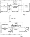
- FIG. 7 illustrates bypass 40.
- a fuse 50a connects the output of photovoltaic panel 10 and the input of test module 20 to bypass electronic module 12 during a flash test of photovoltaic panel 10.
- bypass 40 of electronic module 12 is activated (step 201 ) by virtue of fuse 50a being in an un-blown state as shown in Figure 7 and SPST switch 5b being open circuit.
- SPST switch 5b in an embodiment of the present invention is a reed switch (for example, Part no: HYR 2031-1, Aleph America Corporation NV USA) or a reed relay, or a solid state switch.
- the flash test is performed (step 203 ) using flash test module 20.
- bypass 40 of electronic module 12 is de-activated (step 205 ).
- Figure 8 shows bypass 40 being de-activated (step 205 ).
- Figure 8 shows photovoltaic panel 10 connected to the input of electronic module 12 and a power supply unit (PSU) 13 applied across the output of electronic module 12.
- SPST switch 5b is in a closed position because of the application of magnetic field 52.
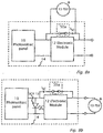
- FIG. 11 illustrates yet another way in which to de-activate bypass 40 (step 205 ) once a flash test has been performed (step 203 ) according to a feature of the present invention.
- Photovoltaic panel 10 is connected to the input of buck boost converter 12a.
- the output of buck boost converter 12a is connected to PSU 13.
- a power line communication superimposed on the output of buck boost converter 12a via PSU 13 a wireless signal applied in the vicinity of buck boost converter 12a, or based on some logic circuitry - i.e. a specific supply voltage applied by PSU 13 causes MOSFETS G C and G A to turn on.
- MOSFETS G C and G A turned on causes a short circuit current I SC to flow from PSU 13 and through fuse 50a.
- the short circuit I SC current blows fuse 50a making fuse 50a open circuit and bypass 40 is de-activated (step 205 ).
- FIG. 8a shows photovoltaic panel 10 connected to the input of electronic module 12 and a power supply unit (PSU) 13 applied across fuse 50a.
- PSU power supply unit
- the application of PSU 13 across fuse 50a causes a short circuit current I SC to flow from PSU 13 and through fuse 50a.
- the short circuit I SC current blows fuse 50a making fuse 50a open circuit and bypass 40 is de-activated (step 205 ).
- FIG. 8b shows photovoltaic panel 10 connected to the input of electronic module 12 and a power supply unit (PSU) 13 applied across the output of electronic module 12.
- PSU power supply unit
- SCR silicon controlled rectifier
- the gate of an SCR 15 is connected inside electronic module 12 in such a way that the application of PSU 13 across the output of electronic module 12 causes a gate signal to be applied to the gate of SCR .
- a gate pulse applied to SCR 15 switches SCR 15 on.
- Alternative ways to get a pulse to the gate of SCR 15 include, power line communication superimposed on the output of electronic module 12 via PSU 13, a wireless signal applied in the vicinity of electronic module 12, or based on some logic circuitry - i.e. a specific supply voltage applied by PSU 13 causes a gate signal to be applied to SCR 15.
- a gate signal applied to SCR 15 and application of PSU 13 applied across the output of electronic module 12, causes a short circuit current I SC to flow from PSU 13 through fuse 50a and SCR 15.
- the short circuit I SC current blows fuse 50a making fuse 50a open circuit and bypass 40 is de-activated (step 205 ).
- Figure 4 illustrates a flowchart for a method for flash testing a photovoltaic panel 10 by bypassing an electronic module 12 according to embodiments of the present invention.
- Figure 4 includes step 201 of activating a bypass, step 203 performing the flash and de-activating the bypass, step 205.
- Figure 9 illustrates bypass 40 when bypass 40 is activated.
- a single pole double throw (SPDT) switch 70, SPST switch 72 and SPDT switch 74 activated by magnetic field of magnet 52, connects the output of photovoltaic panel 10 and the input of test module 20 to perform the function of bypassing electronic module 12 during a flash test of photovoltaic panel 10 .
- SPDT switches 70 and 74 in an embodiment of the present invention is a reed switch (for example, Part no: HYR-1555-form-C, Aleph America Corporation Reno, NV USA) or a reed relay, or a solid state switch.
- SPDT switches 70 and 74 when activated by magnetic field 52 provide open circuit impedance in place of shunt impedance Z T when electronic module 12 is being bypassed during a flash test of photovoltaic panel 10.
- the bypass 40 of electronic module 12 is activated (step 201 ) by applying a magnetic field 52 to SPST switch 72 and SPDT switches 70 and 74 causing switch positions shown in Figure 9 .
- the flash test is performed (step 203 ) using flash test module 20.
- the bypass of electronic module 12 is de-activated by the removal of magnetic field 52 to SPST switch 50 and SPDT switches 70 and 74 (step 205 ).
- Figure 10 shows photovoltaic panel 10 connected to electronic module 12 with SPST switch 50 and SPDT switches 70 and 74 de-activated (step 205 ).
- Electronic module 12 is typically a buck-boost converter circuit to perform DC to DC conversion or an inverter converting DC to AC or a circuit performing maximum power point tracking (MPPT).
- MPPT maximum power point tracking
Landscapes
- Photovoltaic Devices (AREA)
Abstract
Description
- The present application benefits from
US applications 60/992589 filed 5-Dec-2007 61/039050 filed 24 Mar-2008 - The present invention relates to production testing of photovoltaic panels, and more specifically to testing of photovoltaic panels which include integrated circuitry.
- Current voltage (IV) characteristics of a conventional photovoltaic panel are measured using a flash tester. The flash tester measures electrical current characteristics of a photovoltaic panel during a single flash of light of duration typically within one millisecond emitted by the flash lamp. The measurement procedure is based on known properties of a reference photovoltaic panel which has been independently calibrated in an external laboratory. The external laboratory has determined accurately the short circuit current corresponding to standard test conditions (STC) using an AM1.5G spectrum. AM1.5G approximates a standard spectrum of sunlight at the Earth's surface at sea level at high noon in a clear sky as 1000 W/m2. "AM" stands for "air mass" radiation. The 'G' stands for "global" and includes both direct and diffuse radiation. The number "1.5" indicates that the length of the path of light through the atmosphere is 1.5 times that of the shorter path when the sun is directly overhead. During flash testing homogeneity of irradiance over the photovoltaic panel is obtained by a 6-meter distance between the flash lamp and the photovoltaic panel.
- Reference is now made to
Figure 2 which illustrates aconventional flash tester 17. Flash tester includes aflash lamp 16, placed inside a closed lightproof cabin 19 which is painted black inside. Alternatively, black curtains minimize the intensity of reflections towardsphotovoltaic panel 10 from the interior surfaces of the cabin. The homogeneity of irradiance over area ofphotovoltaic panel 10 is measured by placing an irradiance sensor in various positions of the measurement plane. During the flash testing procedure, aflash tester 17 is connected to the output ofphotovoltaic panel 10. The measurement procedure starts with a flash test of a reference photovoltaic panel. The short circuit current is measured during an irradiance corresponding to AM1.5G. The reference photovoltaic panel is then exchanged for the test photovoltaic panel. During a subsequent flash, the irradiance sensor triggers a current-voltage (IV) measurement procedure at the same irradiance as during the measurement of the reference photovoltaic panel. - Conventional photovoltaic panels are typically connected together in series to form strings and the strings are optionally connected in parallel. The combined outputs of the connected photovoltaic panels are typically input to an inverter which converts the generated direct current voltage to alternating current of the grid. Recently, photovoltaic panels have been designed or proposed with integrated circuitry.
- Reference is now made to
Figure 1 which illustrates schematically aphotovoltaic system 14 with a circuit orelectronic module 12 integrated with aphotovoltaic panel 10. The term "electronic module" as used herein refers to electronic circuitry integrated at the output of the photovoltaic panel. The "electronic module" itself may be of the prior art or not of the prior art. A representative reference (Cascade DC-DC Converter Connection of Photovoltaic Modules, G.R. Walker and P.C. Sernia, Power Electronics Specialists Conference, 2002. (PESC02), Vol. 1 IEEE, Cairns, Australia, pp. 24-29) proposes use of DC-DC converters integrated with the photovoltaic panels. The DC-DC converter integrated with the photovoltaic panel is an example of an "electronic module". Other examples of "electronic modules" include, but are not limited to, DC-AC inverters and other power conditioning electronics, as well as sensing and monitoring electronics. - Another reference of the present inventors which describes an example of
photovoltaic system 14 includingphotovoltaic panel 10 integrated withelectronic module 12 isUS20080143188 , entitled "Distributed Power Harvesting Systems Using DC Power Sources". - The "electronic module" herein may have electrical functionality, for instance for improving the electrical conversion efficiency of
photovoltaic system 14. Alternatively, "electronic module" as used herein may have another functionality unrelated to electrical performance. For instance in a co-pending patent application entitled, "Theft detection and Prevention in a Power Generation System", the function ofelectronic module 12 is to protectphotovoltaic system 12 from theft. - Since a standard flash test cannot typically be performed on
panel 10 after integration withelectronic module 12, for instance because the presence ofmodule 12 affects the results of the standard test, it would be advantageous to have a system and method for flash testing of photovoltaic system - The term "photovoltaic panel" as used herein includes any of: one or more solar cells, cells of multiple semiconductor junctions, solar cells connected in different ways (e.g. serial, parallel, serial/parallel), of thin film and/or bulk material, and/or of different materials.
- According to aspects of the present invention there are provided a method for flash testing a photovoltaic panel connected to an electronic module. The electronic module has at least one input attached to the photovoltaic panel and at least one power output. The method of flash testing the photovoltaic panel begins by activating a bypass of the electronic module. The bypass is activated by applying (preferably externally)a magnetic field or an electromagnetic field, The bypass provides a low impedance path between the input and output of the electronic module. The electronic module is typically permanently attached to the photovoltaic panel, The electronic module optionally performs DC to DC conversion or DC to AC conversion. The electronic module optionally performs maximum power point tracking at either the input or the output of the electronic module. The bypass circuit may include a reed switch, or a reed relay switch, a solid state switch or a fuse. After flash testing, the bypass of the electronic module is typically de-activated, by for instance communicating with the electronic module. The bypass may be permanently deactivated, or have an option for re-activation. Re-activation may be beneficial in such scenarios as electronics malfunction (such as disconnect), in which case re-activating the bypass will allow for connection of the photovoltaic panel directly to the output and continued power harvesting. According to aspects of the present invention there is provided a device for flash testing a photovoltaic panel connected to an electronic module. The electronic module has at least one input attached to the photovoltaic panel and at least one power output. A bypass provides a low impedance path between the input and output of the electronic module. The bypass includes a switch between the input and output of the electronic module. The switch may be a magnetically activated reed switch, an electromagnetically activated reed relay or a solid state switch. The electronic module may be, but is not limited to, a DC to DC converter, a DC to AC converter, or a maximum power point tracking module. The bypass includes a fuse and a parallel-connected switch. The parallel-connected switch is disposed between and connected in parallel with the photovoltaic panel and the electronic module. A power supply unit is connected across the output of the electronic module. The parallel-connected switch is closed to provide a low impedance path across the fuse to blow the fuse. The parallel-connected switch includes a silicon controlled rectifier, reed switch, solid state switch, or reed relay. Alternatively, a power supply is connected directly across said fuse and the current flow of the power supply de-activates the bypass by blowing of the fuse. The bypass may include a solid state switch. The bypass is deactivated either permanently ( for instance in the case of a blown fuse) or the bypass may be reactivated as required (in the case of a switch.
- According to still other aspects of the present invention there is provided a device for flash testing a photovoltaic panel connected to an electronic module. The electronic module has at least one input attached to the photovoltaic panel and at least one power output. A bypass applied to the electronic module has two single pole double throw (SPDT) switches and a single pole single throw (SPST) switch. The output node of the photovoltaic panel is connected to the first SPDT switch common. The first output node of the first SPDT is connected to the input node of the electronic module. The second output node of the first SPDT switch is connected to the input node of the SPST switch. The output node of the SPST switch is connected to a first input node of a second SPDT switch. The output node of the electronic module is connected to the second input node of the second SPDT switch. The output node of the second SPDT switch is connected to enclosure output which may be connected to the flash tester.
- The foregoing and/ or other aspects will become apparent from the following detailed description when considered in conjunction with the accompanying drawing figures.
- The invention is herein described, by way of example only, with reference to the accompanying drawings, wherein:
-
FIG. 1 illustrates an electrical power generation system including a photovoltaic panel and electronic module. -
FIG. 2 illustrates a flash test module of the prior art. -
FIG. 3 illustrates a general equivalent circuit, representing the electronic module shown infigures 1 and 2 with a bypass applied, according to a feature of the present invention. -
FIG. 4 shows a flow chart of a method to flash test a photovoltaic panel according to an embodiment of the present invention. -
FIG. 5 is an activated bypass circuit, according to an embodiment of the present invention, of an electronic module connected to a photovoltaic panel and test module. -
FIG. 6 is a de-activated bypass circuit, according to an embodiment of the present invention of an electronic module connected to a photovoltaic panel. -
FIG. 7 is an activated bypass circuit, according to another embodiment of the present invention, of an electronic module connected to a photovoltaic panel and test module. -
FIG. 8 is a de-activated bypass circuit, according to another embodiment of the present invention of an electronic module connected to a photovoltaic panel. -
FIG. 8a is a de-activated bypass circuit using a fuse and power supply, according to another embodiment of the present invention of an electronic module connected to a photovoltaic panel. -
FIG. 8b is a de-activated bypass circuit using a fuse, power supply and silicone controlled rectifier (SCR), according to yet another embodiment of the present invention of an electronic module connected to a photovoltaic panel. -
FIG. 9 is an activated bypass circuit, according to yet another embodiment of the present invention, of an electronic module connected to a photovoltaic panel and test module. -
FIG. 10 is a de-activated bypass circuit, according to yet another embodiment of the present invention of an electronic module connected to a photovoltaic panel. -
Figure 11 illustrates yet another way in which to de-activate bypass once a flash test has been performed according to a feature of the present invention. - Reference will now be made in detail to embodiments of the present invention, examples of which are illustrated in the accompanying drawings; wherein like reference numerals refer to the like elements throughout. The embodiments are described below to explain the present invention by referring to the figures.
- Reference is now made back to
Figure 1 which illustrates electricalpower generation system 14, includingphotovoltaic panel 10 connected toelectronic module 12. In some embodiments of the present invention,electronic module 12 is "permanently attached" tophotovoltaic panel 10. In other embodiments of the present invention, electronic module is integrated withphotovoltaic panel 10 but is not "permanently attached" tophotovoltaic panel 10. The term "permanently attached" as used herein refers to a method or device for attachment such that physical removal or attempt thereof, e.g. ofelectronic module 12 fromphotovoltaic panel 10, would result in damage, e.g. toelectronic module 12 and/orpanel 10. Any mechanism known in the art for "permanently attaching" may be applied in different embodiments of the present invention. Whenelectronic module 12 is permanently attached to thephotovoltaic panel 10, the operation ofphotovoltaic panel 10 ceases or connections thereof are broken on attempting to removeelectronic module 12 fromphotovoltaic panel 10. One such mechanism for permanently attaching uses a thermoset adhesive, e.g. epoxy based resin, and hardener. - Referring to
Figure 3 , an example ofelectronic module 12 is illustrated in more detail.Electronic module 12 connectsphotovoltaic panel 10 andtest module 20. Impedance Z1 is the series equivalent impedance ofelectronic module 12. Impedance Z2 is the equivalent input impedance ofelectronic module 12. Impedance Z3 is the equivalent output impedance ofelectronic module 12.Bypass link 40 when applied between the output ofphotovoltaic panel 10 and the input oftest module 20 eliminates the effects of series equivalent impedance Z1 during a flash test. Withbypass link 40 applied, impedances Z2 and Z3 are connected in parallel with resulting shunt impedance ZT given in Eq. 1.
photovoltaic panel 10. - Reference is made to
Figures 4 ,5 and 6 which illustrate embodiments of the present invention.Figure 4 illustrates a flowchart for a method for flash testing aphotovoltaic panel 10 by bypassing anelectronic module 12 according to embodiments of the present invention.Figure 5 and 6 are corresponding system drawings according to embodiments of the present invention of electricalpower generation system 14.Figure 5 illustratesbypass 40 whenbypass 40 is activated. With reference toFigure 5 , a single pole single throw (SPST) switch 50 activated by magnetic field ofmagnet 52 connects the output ofphotovoltaic panel 10 and the input oftest module 20 to bypasselectronic module 12 during a flash test ofphotovoltaic panel 10.SPST switch 50 in an embodiment of the present invention is a reed switch (for example, Part no: HYR 2031-1, Aleph America Corporation NV USA) or a reed relay, or a solid state switch.Bypass 40 ofelectronic module 12 is activated (step 201) by applying amagnetic field 52 toSPST switch 50 causing SPST switch 50 to close as shown inFigure 5 . The flash test is performed (step 203) usingflash test module 20. After the flash test ofphotovoltaic panel 10, bypass 40 ofelectronic module 12 is de-activated by the removal ofmagnetic field 52 to SPST switch 50 (step 205).Figure 6 illustratesphotovoltaic panel 10 connected to the input ofelectronic module 12, withSPST switch 50 bypass de-activated (step 205). - Reference is made to
Figures 7 and 8 which illustrate another embodiment of the present invention..Figure 7 illustratesbypass 40. With reference toFigure 7 , afuse 50a connects the output ofphotovoltaic panel 10 and the input oftest module 20 to bypasselectronic module 12 during a flash test ofphotovoltaic panel 10. Referring back toFigure 4 , bypass 40 ofelectronic module 12 is activated (step 201) by virtue offuse 50a being in an un-blown state as shown inFigure 7 andSPST switch 5b being open circuit.SPST switch 5b in an embodiment of the present invention is a reed switch (for example, Part no: HYR 2031-1, Aleph America Corporation NV USA) or a reed relay, or a solid state switch. The flash test is performed (step 203) usingflash test module 20. After the flash test ofphotovoltaic panel 10, bypass 40 ofelectronic module 12 is de-activated (step 205).Figure 8 shows bypass 40 being de-activated (step 205).Figure 8 showsphotovoltaic panel 10 connected to the input ofelectronic module 12 and a power supply unit (PSU) 13 applied across the output ofelectronic module 12.SPST switch 5b is in a closed position because of the application ofmagnetic field 52. - Reference now made to
Figure 11 which illustrates yet another way in which to de-activate bypass 40 (step 205) once a flash test has been performed (step 203) according to a feature of the present invention.Photovoltaic panel 10 is connected to the input ofbuck boost converter 12a. The output ofbuck boost converter 12a is connected toPSU 13. During deactivation of bypass 40 (step 205), a power line communication superimposed on the output ofbuck boost converter 12a viaPSU 13, a wireless signal applied in the vicinity ofbuck boost converter 12a, or based on some logic circuitry - i.e. a specific supply voltage applied byPSU 13 causes MOSFETS GC and GA to turn on. MOSFETS GC and GA turned on causes a short circuit current ISC to flow fromPSU 13 and throughfuse 50a. The short circuit ISC current blows fuse50a making fuse 50a open circuit and bypass 40 is de-activated (step 205). - The closure of
SPST switch 5b and application ofPSU 13 applied across the output ofelectronic module 12, causes a short circuit current ISC to flow fromPSU 13 throughfuse 50a andSPST switch 5b. The short circuit ISC current blows fuse50a making fuse 50a open circuit and the removal ofmagnetic field 52 de-activates bypass 40 (step 205). - An alternative way of de-activating bypass 40 (step 205) is shown in
Fig. 8a. Fig. 8a showsphotovoltaic panel 10 connected to the input ofelectronic module 12 and a power supply unit (PSU) 13 applied acrossfuse 50a. The application ofPSU 13 acrossfuse 50a, causes a short circuit current ISC to flow fromPSU 13 and throughfuse 50a. The short circuit ISC current blows fuse50a making fuse 50a open circuit and bypass 40 is de-activated (step 205). - Another way of de-activating bypass 40 (step 205) is shown in
Fig. 8b. Fig. 8b showsphotovoltaic panel 10 connected to the input ofelectronic module 12 and a power supply unit (PSU) 13 applied across the output ofelectronic module 12. The anode and cathode of a silicon controlled rectifier (SCR) 15 is connected in parallel across the output ofphotovoltaic panel 10 and the input ofelectronic module 12. The gate of anSCR 15 is connected insideelectronic module 12 in such a way that the application ofPSU 13 across the output ofelectronic module 12 causes a gate signal to be applied to the gate of SCR . A gate pulse applied toSCR 15switches SCR 15 on. Alternative ways to get a pulse to the gate ofSCR 15 include, power line communication superimposed on the output ofelectronic module 12 viaPSU 13, a wireless signal applied in the vicinity ofelectronic module 12, or based on some logic circuitry - i.e. a specific supply voltage applied byPSU 13 causes a gate signal to be applied toSCR 15. A gate signal applied toSCR 15 and application ofPSU 13 applied across the output ofelectronic module 12, causes a short circuit current ISC to flow fromPSU 13 throughfuse 50a andSCR 15. The short circuit ISC current blows fuse50a making fuse 50a open circuit and bypass 40 is de-activated (step 205). - Reference is now made to
Figures 4 ,9 and 10 which illustrate another embodiment of the present invention of electricalpower generation system 14, particularly applicable in cases when the resulting shunt impedance ZT is small enough to disrupt the results of the flash test, such as being less than 1 Mega Ohm inelectronic module 12. Referring back toFigure 4, Figure 4 illustrates a flowchart for a method for flash testing aphotovoltaic panel 10 by bypassing anelectronic module 12 according to embodiments of the present invention.Figure 4 includesstep 201 of activating a bypass, step 203 performing the flash and de-activating the bypass,step 205. -
Figure 9 illustratesbypass 40 whenbypass 40 is activated. With reference toFigure 9 , a single pole double throw (SPDT)switch 70,SPST switch 72 andSPDT switch 74, activated by magnetic field ofmagnet 52, connects the output ofphotovoltaic panel 10 and the input oftest module 20 to perform the function of bypassingelectronic module 12 during a flash test ofphotovoltaic panel 10. SPDT switches 70 and 74 in an embodiment of the present invention is a reed switch (for example, Part no: HYR-1555-form-C, Aleph America Corporation Reno, NV USA) or a reed relay, or a solid state switch. SPDT switches 70 and 74 when activated bymagnetic field 52 provide open circuit impedance in place of shunt impedance ZT whenelectronic module 12 is being bypassed during a flash test ofphotovoltaic panel 10. Thebypass 40 ofelectronic module 12 is activated (step 201) by applying amagnetic field 52 toSPST switch 72 and SPDT switches 70 and 74 causing switch positions shown inFigure 9 . Next the flash test is performed (step 203) usingflash test module 20. After the flash test ofphotovoltaic panel 10, the bypass ofelectronic module 12 is de-activated by the removal ofmagnetic field 52 toSPST switch 50 and SPDT switches 70 and 74 (step 205).Figure 10 showsphotovoltaic panel 10 connected toelectronic module 12 withSPST switch 50 and SPDT switches 70 and 74 de-activated (step 205). - During operation of electrical
power generation system 14, DC power is produced byphotovoltaic panel 10 and transferred to the input ofelectronic module 12.Electronic module 12 is typically a buck-boost converter circuit to perform DC to DC conversion or an inverter converting DC to AC or a circuit performing maximum power point tracking (MPPT). - While the invention has been described with respect to a limited number of embodiments, it will be appreciated that many variations, modifications and other applications of the invention may be made.
- The claim set as filed in the original application is repeated now as clauses in order to preserve all the subject matter of the original application in the present divisional application.
- Clause 1: A method for testing a photovoltaic panel connected to an electronic module, said electronic module including at least one input attached to said photovoltaic panel and at least one power output, the method comprising the step of: activating a bypass to said electronic module; wherein said bypass provides a low impedance path between said at least one power output and said at least one input of said electronic module.
- Clause 2: The method according to
clause 1, further comprising the step of: permanently attaching the electronic module to the photovoltaic panel. - Clause 3: The method according to
clause 1, wherein said activating includes externally applying selectably either an electromagnetic field or a magnetic field. - Clause 4: The method according to
clause 1, wherein the electronic module performs selectably either: DC to DC conversion, DC to AC conversion or maximum power point tracking. - Clause 5: The method according to
clause 1, wherein the electronic module performs maximum power point tracking to maximize power at selectably either: the at least one input or the least one power output. - Clause 6: The method according to
clause 1, wherein said bypass includes selectably either a reed switch, a reed relay switch, a solid state switch or a fuse. - Clause 7: The method according to
clause 1, wherein said bypass includes a fuse and wherein a parallel connected switch is disposed between and connected in parallel with the photovoltaic panel and the electronic module, the method further comprising the steps of: connecting a power supply unit across the outputs of the electronic module; and closing the switch to provide a low impedance path across the fuse, thereby blowing of fuse. - Clause 8: The method according to clause 7, wherein said parallel-connected switch is selected from a group comprising of a silicon controlled rectifier, reed switch, solid state switch, reed relay.
- Clause 9: The method according to
clause 1, wherein said bypass includes a fuse further comprising the step connecting a power supply directly across said fuse, wherein current flow from the power supply, de-activates the bypass by blowing said fuse. - Clause 10: The method according to
clause 1, wherein said bypass includes a solid state switch. - Clause 11: The method according to
clause 1, further comprising the step of: de-activating said bypass of the electronic module. - Clause 12: The method according to clause 11, wherein said de-activating said bypass is performed by communicating with the electronic module.
- Clause 13: A device for testing a photovoltaic panel system including a photovoltaic panel connected to an electronic module, said electronic module including at least one input attached to said photovoltaic panel and at least one power output, the system comprising: a bypass to said electronic module, wherein said bypass provides a low impedance path between said at least one power output and said at least one input of said electronic module.
- Clause 14: The device, according
clause 13, wherein said bypass includes a bypass component selected from the group consisting of: at least one switch and at least one fuse, said bypass component connecting the at least one power output and the at least one input of the electronic module. - Clause 15: The device, according
clause 14, wherein said at least one switch includes selectably either: a magnetically activated reed switch;
an electro-magnetically activated reed relay switch; or a solid state switch. - Clause 16: The device, according
clause 13, wherein said electronic module performs selectably either: DC to DC conversion; maximum power point tracking; or DC to AC conversion. - Clause 17: A device for testing a photovoltaic panel system including a photovoltaic panel connected to an electronic module, the electronic module including at least one input attached to the photovoltaic panel and at least one power output, the device comprising: a first single pole double throw switch, said single pole double throw switch including a common node, a first output node and a second output node; a first single pole single throw switch including an input node and an output node; a second single pole double throw switch, said single pole double throw switch including a common node, a first input node and a second input node; an output node of the photovoltaic panel connected to said common node of said single pole double pole switch; said first output node of said first single pole double throw switch connected to input node of the electronic module; said second output node connected to input node of a first single pole single throw switch; output node of said first single pole single throw switch connected to a first input node of said second single pole double throw switch; output node of said electronic module connected to second input node of said second single pole double throw switch.
Claims (15)
- An apparatus comprising:a direct current to direct current (DC/DC) converter configured to perform power conversion from an input of the DC/DC converter to an output of DC/DC converter; anda bypass link electrically coupled between the input of the DC/DC converter and the output of the DC/DC converter, the bypass link comprising a first switch, wherein the bypass link can be activated and deactivated using the first switch,wherein when the first switch is closed, the bypass link is activated to provide a low impedance path between an output of a photovoltaic panel and the output of the DC/DC converter.
- The apparatus of claim 1, wherein the bypass link is configured to activate responsive to a malfunction in the DC/DC converter.
- The apparatus of any of claims 1 and 2, wherein the DC/DC converter is connected to the photovoltaic panel.
- The apparatus of any of claims 1-3, wherein the first switch is a solid state switch.
- The apparatus of any of claims 1-4, wherein the bypass link further comprises one or more switches serially connected to the first switch.
- The apparatus of any of claims 1-5, wherein the bypass link is activated by applying a signal to the first switch.
- The apparatus of any of claims 1-6, wherein the bypass link is de-activated in response to a communication signal.
- The apparatus of any of claims 1-7, wherein the DC/DC converter is a buck-boost converter.
- A method comprising:receiving power from a photovoltaic panel at an input of a DC/DC converter;converting the received power and outputting the converted power to an output of the DC/DC converter; andclosing a switch of a bypass link to activate a bypass of the DC/DC converter, wherein the bypass link is electrically coupled between the input of the DC/DC converter and the output of the DC/DC converter, and wherein the bypass link, when activated, provides a low impedance path between the input of the DC/DC converter and the output of the DC/DC converter.
- The method of claim 9, wherein the bypass link is activated responsive to a malfunction of the DC/DC converter.
- The method of any of claims 9 and 10, further comprising deactivating the bypass link.
- The method of any of claims 9-11, wherein the DC/DC converter is a buck-boost converter.
- The method of any of claims 9-12, further comprising de-activating the bypass link responsive to a communication signal.
- The method of any of claims 9-13, wherein the switch is a solid state switch.
- The method of any of claims 9-14, wherein the DC/DC converter is connected to the photovoltaic panel.
Applications Claiming Priority (4)
| Application Number | Priority Date | Filing Date | Title |
|---|---|---|---|
| US99258907P | 2007-12-05 | 2007-12-05 | |
| US3905008P | 2008-03-24 | 2008-03-24 | |
| EP08856716.9A EP2225778B1 (en) | 2007-12-05 | 2008-12-04 | Testing of a photovoltaic panel |
| PCT/IB2008/055095 WO2009072077A1 (en) | 2007-12-05 | 2008-12-04 | Testing of a photovoltaic panel |
Related Parent Applications (1)
| Application Number | Title | Priority Date | Filing Date |
|---|---|---|---|
| EP08856716.9A Division EP2225778B1 (en) | 2007-12-05 | 2008-12-04 | Testing of a photovoltaic panel |
Publications (1)
| Publication Number | Publication Date |
|---|---|
| EP3561881A1 true EP3561881A1 (en) | 2019-10-30 |
Family
ID=40568264
Family Applications (2)
| Application Number | Title | Priority Date | Filing Date |
|---|---|---|---|
| EP19181247.8A Pending EP3561881A1 (en) | 2007-12-05 | 2008-12-04 | Testing of a photovoltaic panel |
| EP08856716.9A Active EP2225778B1 (en) | 2007-12-05 | 2008-12-04 | Testing of a photovoltaic panel |
Family Applications After (1)
| Application Number | Title | Priority Date | Filing Date |
|---|---|---|---|
| EP08856716.9A Active EP2225778B1 (en) | 2007-12-05 | 2008-12-04 | Testing of a photovoltaic panel |
Country Status (3)
| Country | Link |
|---|---|
| US (1) | US8324921B2 (en) |
| EP (2) | EP3561881A1 (en) |
| WO (1) | WO2009072077A1 (en) |
Families Citing this family (86)
| Publication number | Priority date | Publication date | Assignee | Title |
|---|---|---|---|---|
| US11881814B2 (en) | 2005-12-05 | 2024-01-23 | Solaredge Technologies Ltd. | Testing of a photovoltaic panel |
| US10693415B2 (en) | 2007-12-05 | 2020-06-23 | Solaredge Technologies Ltd. | Testing of a photovoltaic panel |
| US11728768B2 (en) | 2006-12-06 | 2023-08-15 | Solaredge Technologies Ltd. | Pairing of components in a direct current distributed power generation system |
| US9088178B2 (en) | 2006-12-06 | 2015-07-21 | Solaredge Technologies Ltd | Distributed power harvesting systems using DC power sources |
| US11735910B2 (en) | 2006-12-06 | 2023-08-22 | Solaredge Technologies Ltd. | Distributed power system using direct current power sources |
| US8013472B2 (en) | 2006-12-06 | 2011-09-06 | Solaredge, Ltd. | Method for distributed power harvesting using DC power sources |
| US11309832B2 (en) | 2006-12-06 | 2022-04-19 | Solaredge Technologies Ltd. | Distributed power harvesting systems using DC power sources |
| US8319471B2 (en) | 2006-12-06 | 2012-11-27 | Solaredge, Ltd. | Battery power delivery module |
| US11888387B2 (en) | 2006-12-06 | 2024-01-30 | Solaredge Technologies Ltd. | Safety mechanisms, wake up and shutdown methods in distributed power installations |
| US8816535B2 (en) | 2007-10-10 | 2014-08-26 | Solaredge Technologies, Ltd. | System and method for protection during inverter shutdown in distributed power installations |
| US8384243B2 (en) | 2007-12-04 | 2013-02-26 | Solaredge Technologies Ltd. | Distributed power harvesting systems using DC power sources |
| US11855231B2 (en) | 2006-12-06 | 2023-12-26 | Solaredge Technologies Ltd. | Distributed power harvesting systems using DC power sources |
| US8473250B2 (en) | 2006-12-06 | 2013-06-25 | Solaredge, Ltd. | Monitoring of distributed power harvesting systems using DC power sources |
| US8319483B2 (en) | 2007-08-06 | 2012-11-27 | Solaredge Technologies Ltd. | Digital average input current control in power converter |
| US11687112B2 (en) | 2006-12-06 | 2023-06-27 | Solaredge Technologies Ltd. | Distributed power harvesting systems using DC power sources |
| US8947194B2 (en) | 2009-05-26 | 2015-02-03 | Solaredge Technologies Ltd. | Theft detection and prevention in a power generation system |
| US9112379B2 (en) | 2006-12-06 | 2015-08-18 | Solaredge Technologies Ltd. | Pairing of components in a direct current distributed power generation system |
| US11296650B2 (en) | 2006-12-06 | 2022-04-05 | Solaredge Technologies Ltd. | System and method for protection during inverter shutdown in distributed power installations |
| US11569659B2 (en) | 2006-12-06 | 2023-01-31 | Solaredge Technologies Ltd. | Distributed power harvesting systems using DC power sources |
| US9130401B2 (en) | 2006-12-06 | 2015-09-08 | Solaredge Technologies Ltd. | Distributed power harvesting systems using DC power sources |
| US8963369B2 (en) | 2007-12-04 | 2015-02-24 | Solaredge Technologies Ltd. | Distributed power harvesting systems using DC power sources |
| US8618692B2 (en) | 2007-12-04 | 2013-12-31 | Solaredge Technologies Ltd. | Distributed power system using direct current power sources |
| WO2009055474A1 (en) | 2007-10-23 | 2009-04-30 | And, Llc | High reliability power systems and solar power converters |
| CA2737134C (en) | 2007-10-15 | 2017-10-10 | Ampt, Llc | Systems for highly efficient solar power |
| US8289742B2 (en) | 2007-12-05 | 2012-10-16 | Solaredge Ltd. | Parallel connected inverters |
| WO2009072076A2 (en) | 2007-12-05 | 2009-06-11 | Solaredge Technologies Ltd. | Current sensing on a mosfet |
| US11264947B2 (en) | 2007-12-05 | 2022-03-01 | Solaredge Technologies Ltd. | Testing of a photovoltaic panel |
| CN101933209B (en) | 2007-12-05 | 2015-10-21 | 太阳能安吉有限公司 | Release mechanism in distributed electrical power apparatus, to wake up and method for closing |
| US9291696B2 (en) | 2007-12-05 | 2016-03-22 | Solaredge Technologies Ltd. | Photovoltaic system power tracking method |
| US8111052B2 (en) | 2008-03-24 | 2012-02-07 | Solaredge Technologies Ltd. | Zero voltage switching |
| EP2294669B8 (en) | 2008-05-05 | 2016-12-07 | Solaredge Technologies Ltd. | Direct current power combiner |
| FR2944647B1 (en) * | 2009-04-17 | 2011-08-05 | Commissariat Energie Atomique | METHOD FOR DIAGNOSING THE FAILURE OF A PHOTOVOLTAIC GENERATOR |
| WO2010120315A1 (en) | 2009-04-17 | 2010-10-21 | Ampt, Llc | Methods and apparatus for adaptive operation of solar power systems |
| CN102422429B (en) | 2009-05-22 | 2014-08-06 | 太阳能安吉科技有限公司 | Electrically isolated heat dissipating junction box |
| WO2011049985A1 (en) | 2009-10-19 | 2011-04-28 | Ampt, Llc | Novel solar panel string converter topology |
| FR2951886B1 (en) * | 2009-10-23 | 2016-02-05 | Commissariat Energie Atomique | CONTROL WITH SLOWDOWN OF THE OPENING OF AN ELECTRONIC SWITCH |
| US8710699B2 (en) | 2009-12-01 | 2014-04-29 | Solaredge Technologies Ltd. | Dual use photovoltaic system |
| US8766696B2 (en) | 2010-01-27 | 2014-07-01 | Solaredge Technologies Ltd. | Fast voltage level shifter circuit |
| DE102010009080B4 (en) * | 2010-02-24 | 2018-02-22 | Adensis Gmbh | Method and device for finding low-power PV modules in a PV system |
| DE102010009079B4 (en) * | 2010-02-24 | 2018-02-22 | Adensis Gmbh | Method and device for finding low-power PV modules in a PV system by means of disconnectors |
| CN104766426B (en) * | 2010-05-31 | 2017-06-30 | 太阳能安吉科技有限公司 | Theft in electricity generation system is detected and prevented |
| CN102918571B (en) * | 2010-05-31 | 2015-04-01 | 太阳能安吉科技有限公司 | Theft detection and prevention in a power generation system |
| US8508208B2 (en) * | 2010-07-02 | 2013-08-13 | Fairchild Semiconductor Corporation | Buck-boost regulator with converter bypass function |
| EP2408096A1 (en) * | 2010-07-12 | 2012-01-18 | ABB Oy | Current-fed converter with quadratic conversion ratio |
| EP2408097A1 (en) * | 2010-07-12 | 2012-01-18 | ABB Oy | Current-fed converter |
| IT1402319B1 (en) * | 2010-09-08 | 2013-08-30 | Innovazione En Rinnovabili Srl | SELF-POWERED CIRCUIT FOR WIRELESS REMOTE MONITORING OF PHOTOVOLTAIC PANELS |
| US10673229B2 (en) | 2010-11-09 | 2020-06-02 | Solaredge Technologies Ltd. | Arc detection and prevention in a power generation system |
| GB2485527B (en) | 2010-11-09 | 2012-12-19 | Solaredge Technologies Ltd | Arc detection and prevention in a power generation system |
| US10230310B2 (en) | 2016-04-05 | 2019-03-12 | Solaredge Technologies Ltd | Safety switch for photovoltaic systems |
| US10673222B2 (en) | 2010-11-09 | 2020-06-02 | Solaredge Technologies Ltd. | Arc detection and prevention in a power generation system |
| GB2486408A (en) | 2010-12-09 | 2012-06-20 | Solaredge Technologies Ltd | Disconnection of a string carrying direct current |
| GB2483317B (en) | 2011-01-12 | 2012-08-22 | Solaredge Technologies Ltd | Serially connected inverters |
| US8841916B2 (en) * | 2011-02-28 | 2014-09-23 | Tigo Energy, Inc. | System and method for flash bypass |
| US8193788B2 (en) * | 2011-04-27 | 2012-06-05 | Solarbridge Technologies, Inc. | Method and device for controlling a configurable power supply to provide AC and/or DC power output |
| US8570005B2 (en) | 2011-09-12 | 2013-10-29 | Solaredge Technologies Ltd. | Direct current link circuit |
| FR2982373B1 (en) * | 2011-11-03 | 2014-06-13 | Augier | DEVICE FOR AIDING THE MAINTENANCE OF A PHOTOVOLTAIC INSTALLATION. |
| DE102011089188A1 (en) * | 2011-12-20 | 2013-06-20 | Enextra Gmbh | Device for photovoltaic systems and photovoltaic system |
| GB2498365A (en) | 2012-01-11 | 2013-07-17 | Solaredge Technologies Ltd | Photovoltaic module |
| GB2498791A (en) | 2012-01-30 | 2013-07-31 | Solaredge Technologies Ltd | Photovoltaic panel circuitry |
| GB2498790A (en) | 2012-01-30 | 2013-07-31 | Solaredge Technologies Ltd | Maximising power in a photovoltaic distributed power system |
| US9853565B2 (en) | 2012-01-30 | 2017-12-26 | Solaredge Technologies Ltd. | Maximized power in a photovoltaic distributed power system |
| GB2499991A (en) | 2012-03-05 | 2013-09-11 | Solaredge Technologies Ltd | DC link circuit for photovoltaic array |
| CN102621394B (en) * | 2012-03-30 | 2014-07-09 | 广东易事特电源股份有限公司 | System and method for detecting insulation resistance to ground of dual-branch input photovoltaic grid-connected inverter |
| EP2859650B1 (en) | 2012-05-25 | 2017-02-15 | Solaredge Technologies Ltd. | Circuit for interconnected direct current power sources |
| US10115841B2 (en) | 2012-06-04 | 2018-10-30 | Solaredge Technologies Ltd. | Integrated photovoltaic panel circuitry |
| US20130328404A1 (en) * | 2012-06-11 | 2013-12-12 | Panasonic Corporation | Voltage conversion apparatus, power generation system, and voltage conversion method |
| CN104854528B (en) | 2012-10-16 | 2017-04-12 | 沃尔泰拉半导体公司 | Systems and methods for controlling maximum power point tracking controllers |
| US9105765B2 (en) | 2012-12-18 | 2015-08-11 | Enphase Energy, Inc. | Smart junction box for a photovoltaic system |
| US9941813B2 (en) | 2013-03-14 | 2018-04-10 | Solaredge Technologies Ltd. | High frequency multi-level inverter |
| US9548619B2 (en) | 2013-03-14 | 2017-01-17 | Solaredge Technologies Ltd. | Method and apparatus for storing and depleting energy |
| US9397497B2 (en) | 2013-03-15 | 2016-07-19 | Ampt, Llc | High efficiency interleaved solar power supply system |
| EP4318001A3 (en) | 2013-03-15 | 2024-05-01 | Solaredge Technologies Ltd. | Bypass mechanism |
| US9318974B2 (en) | 2014-03-26 | 2016-04-19 | Solaredge Technologies Ltd. | Multi-level inverter with flying capacitor topology |
| US20150302723A1 (en) * | 2014-04-16 | 2015-10-22 | Ark Corporation Pty Ltd | Battery Monitor and Controller |
| CN104993787B (en) * | 2015-07-16 | 2017-03-08 | 广州市浦来能源科技有限公司 | A kind of photovoltaic optimizer of random waveform output |
| CN105337519B (en) * | 2015-11-18 | 2018-05-01 | 阳光电源股份有限公司 | The self-checking system and self checking method of cascade multilevel converter |
| CN107153212B (en) | 2016-03-03 | 2023-07-28 | 太阳能安吉科技有限公司 | Method for mapping a power generation facility |
| US10599113B2 (en) | 2016-03-03 | 2020-03-24 | Solaredge Technologies Ltd. | Apparatus and method for determining an order of power devices in power generation systems |
| US11081608B2 (en) | 2016-03-03 | 2021-08-03 | Solaredge Technologies Ltd. | Apparatus and method for determining an order of power devices in power generation systems |
| US11018623B2 (en) | 2016-04-05 | 2021-05-25 | Solaredge Technologies Ltd. | Safety switch for photovoltaic systems |
| US11177663B2 (en) | 2016-04-05 | 2021-11-16 | Solaredge Technologies Ltd. | Chain of power devices |
| CN105790704A (en) * | 2016-06-03 | 2016-07-20 | 浙江人和光伏科技有限公司 | Junction box for solar cell |
| CN207069982U (en) * | 2017-08-30 | 2018-03-02 | 米亚索乐装备集成(福建)有限公司 | Support meanss for flexible solar battery performance test |
| CN109193610B (en) | 2018-09-28 | 2021-01-08 | 阳光电源股份有限公司 | Shutdown control system and method |
| EP3951557A4 (en) * | 2019-03-28 | 2023-03-01 | Hernández Martínez, Bhishma | Diagnostic module of a photovoltaic panel |
| CN112910252A (en) * | 2021-01-27 | 2021-06-04 | 维沃移动通信有限公司 | Electronic equipment and control method thereof |
Citations (9)
| Publication number | Priority date | Publication date | Assignee | Title |
|---|---|---|---|---|
| JPS62154122A (en) * | 1985-12-27 | 1987-07-09 | Kyocera Corp | Charging control system in solar generating device |
| EP0756178A2 (en) * | 1995-07-26 | 1997-01-29 | Canon Kabushiki Kaisha | Power supply device characteristic measuring apparatus and method |
| JPH1146457A (en) * | 1997-07-25 | 1999-02-16 | Tdk Corp | Charging device utilizing solar cell |
| WO2000000839A1 (en) * | 1998-06-26 | 2000-01-06 | Fraunhofer-Gesellschaft zur Förderung der angewandten Forschung e.V. | Device for testing solar home systems |
| WO2006007198A1 (en) * | 2004-06-29 | 2006-01-19 | Eaton Power Quality Corporation | Method and apparatus for testing uniterruptible power supply |
| DE102005030907A1 (en) * | 2005-06-30 | 2007-01-11 | Pairan Elektronik Gmbh | Multiple string solar generator isolation resistance test procedure connects plus and minus poles of all other strings to measure string under test |
| EP1887675A2 (en) * | 2006-08-08 | 2008-02-13 | Siemens Aktiengesellschaft Österreich | Photovoltaic facility with insulating resistance measurement of solar generators and method for operating the same |
| WO2008132551A2 (en) * | 2006-12-06 | 2008-11-06 | Solaredge Technologies | Current bypass for distributed power harvesting systems using dc power sources |
| EP2179451A1 (en) * | 2007-10-12 | 2010-04-28 | Fraunhofer-Gesellschaft zur Förderung der angewandten Forschung e.V. | Controllable switch-over device for a solar module |
Family Cites Families (334)
| Publication number | Priority date | Publication date | Assignee | Title |
|---|---|---|---|---|
| US3369210A (en) * | 1965-07-28 | 1968-02-13 | Electro Nite | Electrical connector |
| US3596229A (en) * | 1969-04-28 | 1971-07-27 | Wago Kontakttechnik Gmbh | Electrical connector |
| FR2393448A1 (en) * | 1976-08-18 | 1978-12-29 | Wago Kontakttechnik Gmbh | ELECTRICAL CONNECTION OR CONNECTION DEVICE |
| US4060757A (en) * | 1976-09-17 | 1977-11-29 | General Electric Co. | Inverters having a transformer-coupled commutating circuit |
| US4101816A (en) * | 1976-11-03 | 1978-07-18 | Vibra-Metrics, Inc. | Switch control system |
| USRE33057E (en) * | 1980-06-23 | 1989-09-12 | Brigham Young University | High frequency supply system for gas discharge lamps and electronic ballast therefor |
| US4460232A (en) * | 1982-05-24 | 1984-07-17 | Amp, Incorporated | Junction box for solar modules |
| US4481654A (en) * | 1982-09-09 | 1984-11-06 | General Electric Company | X-Ray tube bias supply |
| US4452867A (en) * | 1983-02-28 | 1984-06-05 | Pittway Corporation | Storage battery containing voltage reducing means |
| US4623753A (en) * | 1983-10-31 | 1986-11-18 | Amp Incorporated | Watertight junction box |
| JPH0710149B2 (en) * | 1984-02-20 | 1995-02-01 | 日本電装株式会社 | Vehicle charge control device |
| US4644458A (en) * | 1984-03-19 | 1987-02-17 | Nec Corporation | Electric power supply circuit capable of reducing a loss of electric power |
| JPS60249832A (en) * | 1984-05-25 | 1985-12-10 | 株式会社東芝 | Method of protecting inverter |
| US4554515A (en) * | 1984-07-06 | 1985-11-19 | At&T Laboratories | CMOS Operational amplifier |
| US4598330A (en) * | 1984-10-31 | 1986-07-01 | International Business Machines Corporation | High power direct current switching circuit |
| US4637677A (en) * | 1984-12-18 | 1987-01-20 | Amp Incorporated | Electrical connector |
| JPS61173636A (en) * | 1984-12-18 | 1986-08-05 | 三菱電機株式会社 | Power source unit |
| US4888063A (en) * | 1985-11-21 | 1989-12-19 | Powell Roger A | Variable aperture, variable flux density, aerospace solar collector |
| US4799059A (en) | 1986-03-14 | 1989-01-17 | Enscan, Inc. | Automatic/remote RF instrument monitoring system |
| US4783728A (en) * | 1986-04-29 | 1988-11-08 | Modular Power Corp. | Modular power supply with PLL control |
| US4888702A (en) * | 1987-08-20 | 1989-12-19 | Integrated Power Corporation | Photovoltaic system controller |
| FR2634293B2 (en) * | 1988-01-29 | 1990-10-19 | Centre Nat Etd Spatiales | SYSTEM FOR REGULATING THE OPERATING POINT OF A DIRECT CURRENT SUPPLY IN A VOLTAGE OR CURRENT GENERATOR CHARACTERISTIC AREA |
| US4868379A (en) * | 1988-06-20 | 1989-09-19 | Utility Power Group | Photovoltaic array with two-axis power maximization tracking |
| US4903851A (en) * | 1988-07-07 | 1990-02-27 | Slough Donovan L | Molded plastic stud box support and box |
| US4987360A (en) * | 1988-12-27 | 1991-01-22 | Bill's Ice Cream, Inc. | Self-contained rechargeable battery power source with voltage reducer |
| JPH079442B2 (en) | 1989-09-20 | 1995-02-01 | 株式会社東芝 | Current detection circuit |
| US5081558A (en) * | 1990-02-02 | 1992-01-14 | Northrop Corporation | High voltage DC relays |
| US5045988A (en) * | 1990-07-31 | 1991-09-03 | Eaton Corporation | Isolated adjustable frequency AC inverter control |
| DE4038225A1 (en) * | 1990-11-30 | 1992-06-04 | Bosch Gmbh Robert | METHOD AND DEVICE FOR VOLTAGE REGULATION DEPENDING ON THE BATTERY CHARGE STATE |
| US6933627B2 (en) | 1991-01-08 | 2005-08-23 | Nextek Power Systems Inc. | High efficiency lighting system |
| JPH04299027A (en) * | 1991-03-27 | 1992-10-22 | Toshiba Corp | Inverter device |
| US5327071A (en) * | 1991-11-05 | 1994-07-05 | The United States Of America As Represented By The Administrator Of The National Aeronautics & Space Administration | Microprocessor control of multiple peak power tracking DC/DC converters for use with solar cell arrays |
| US5345375A (en) * | 1991-12-16 | 1994-09-06 | Regents Of The University Of Minnesota | System and method for reducing harmonic currents by current injection |
| US5245527A (en) | 1991-12-24 | 1993-09-14 | Siemens Electric Limited | Modular ac drive controller |
| GB2264403B (en) * | 1992-02-18 | 1996-09-04 | Hitachi Ltd | An apparatus for controlling parallel running of inverters |
| JP2809026B2 (en) * | 1992-09-30 | 1998-10-08 | 三菱電機株式会社 | INVERTER DEVICE AND METHOD OF USING INVERTER DEVICE |
| JP2882952B2 (en) * | 1992-10-19 | 1999-04-19 | キヤノン株式会社 | Power generator |
| EP0604777A1 (en) | 1992-12-28 | 1994-07-06 | Motorola, Inc. | Data transmission device system and method |
| JP2626868B2 (en) * | 1993-03-08 | 1997-07-02 | モレックス インコーポレーテッド | Terminal of electrical connector and method of manufacturing the same |
| US5493154A (en) * | 1993-04-21 | 1996-02-20 | Astec International, Ltd. | Temperature share scheme |
| US5402060A (en) * | 1993-05-13 | 1995-03-28 | Toko America, Inc. | Controller for two-switch buck-boost converter |
| US6862349B1 (en) | 1993-05-28 | 2005-03-01 | Mediaone Group, Inc. | Method and apparatus for delivering secured telephony service in a hybrid coaxial cable network |
| SE514827C2 (en) * | 1993-12-09 | 2001-04-30 | Abb Ab | DC switch for high power |
| JP3029185B2 (en) * | 1994-04-12 | 2000-04-04 | キヤノン株式会社 | Islanding prevention device, distributed power generation device and power generation system using the same |
| DE19515786C2 (en) * | 1994-04-28 | 1997-08-21 | Kyocera Corp | Solar energy system |
| JP3298738B2 (en) * | 1994-05-19 | 2002-07-08 | 富士通株式会社 | Communication device |
| DE69532041T2 (en) * | 1994-09-16 | 2004-07-01 | Kraft Foods North America, Inc., Northfield | FOAMING COFFEE CREAM AND HOT INSTANT CAPPUCCINO |
| US5659465A (en) * | 1994-09-23 | 1997-08-19 | Aeroviroment, Inc. | Peak electrical power conversion system |
| US5604430A (en) * | 1994-10-11 | 1997-02-18 | Trw Inc. | Solar array maximum power tracker with arcjet load |
| WO1996013093A1 (en) | 1994-10-24 | 1996-05-02 | Hitachi, Ltd. | Inverter device |
| DE4446303C2 (en) * | 1994-12-23 | 1997-01-23 | Deutsche Forsch Luft Raumfahrt | Device for concentrating solar radiation |
| US5777515A (en) * | 1995-05-11 | 1998-07-07 | Matsushita Electric Industrial Co., Ltd. | Operational amplifier apparatus |
| JP3651972B2 (en) * | 1995-07-26 | 2005-05-25 | キヤノン株式会社 | Control device for grid-connected inverter and photovoltaic power generation system using the same |
| JPH0962387A (en) * | 1995-08-29 | 1997-03-07 | Canon Inc | Method and device for power control of battery power source and battery power source system |
| JP3382434B2 (en) * | 1995-09-22 | 2003-03-04 | キヤノン株式会社 | Battery power supply voltage control device and voltage control method |
| US5798631A (en) * | 1995-10-02 | 1998-08-25 | The State Of Oregon Acting By And Through The State Board Of Higher Education On Behalf Of Oregon State University | Performance optimization controller and control method for doubly-fed machines |
| US5646501A (en) * | 1995-11-02 | 1997-07-08 | Lucent Technologies Inc. | Flexible power architecture which supports multiple battery technologies for use with a portable device |
| KR970048612A (en) * | 1995-12-29 | 1997-07-29 | 김주용 | Solar Tracking System and Method Using Solar Array |
| US5822186A (en) * | 1996-02-23 | 1998-10-13 | Apple Computer, Inc. | Auxiliary electrical component utilized on the exterior of an electrical device that can be removed when the electrical device is powered |
| JP3591978B2 (en) * | 1996-04-12 | 2004-11-24 | キヤノン株式会社 | Fluid supply device powered by unstable power supply |
| KR100205229B1 (en) * | 1996-05-15 | 1999-07-01 | 윤종용 | The source for solar cells |
| US5801519A (en) * | 1996-06-21 | 1998-09-01 | The Board Of Trustees Of The University Of Illinois | Self-excited power minimizer/maximizer for switching power converters and switching motor drive applications |
| EP0817350B1 (en) * | 1996-06-24 | 2008-03-26 | SANYO ELECTRIC Co., Ltd. | Power-supply system involving system interconnection |
| US5804894A (en) * | 1996-08-16 | 1998-09-08 | Telxon Corporation | Low voltage battery pack monitoring circuit with adjustable set points |
| JP3571860B2 (en) | 1996-08-23 | 2004-09-29 | キヤノン株式会社 | Motor driving device using an unstable power supply |
| US5773963A (en) * | 1996-08-29 | 1998-06-30 | Apple Computer Inc. | Method and apparatus for programmably adjusting output voltage of a battery charger |
| JP3352334B2 (en) | 1996-08-30 | 2002-12-03 | キヤノン株式会社 | Solar cell power controller |
| JP3554116B2 (en) * | 1996-09-06 | 2004-08-18 | キヤノン株式会社 | Power control device and solar power generation system using the same |
| JPH10136574A (en) * | 1996-10-31 | 1998-05-22 | Hitachi Ltd | Battery control device |
| SE515366C2 (en) | 1996-11-20 | 2001-07-23 | Ericsson Telefon Ab L M | Battery pack for a portable electrical appliance and way of charging the same |
| US5905645A (en) * | 1996-12-02 | 1999-05-18 | Astec International Limited | Thermally aided power sharing of power supplies with or without an external current share line |
| JP3630967B2 (en) * | 1997-01-21 | 2005-03-23 | キヤノン株式会社 | Solar cell array and solar power generation device |
| US6104209A (en) * | 1998-08-27 | 2000-08-15 | Micron Technology, Inc. | Low skew differential receiver with disable feature |
| DE19709766C1 (en) * | 1997-03-10 | 1998-09-03 | Siemens Ag | Controlling several coupled end stages esp. with gradient amplifier of nuclear resonance tomography e.g. Project 039 |
| US6353929B1 (en) | 1997-06-23 | 2002-03-05 | One River Worldtrek, Inc. | Cooperative system for measuring electronic media |
| DE19737286C2 (en) | 1997-08-27 | 2000-05-31 | Webasto Karosseriesysteme | Solar panel |
| US5945806A (en) * | 1997-08-29 | 1999-08-31 | Compaq Computer Corporation | Variable-voltage programmable battery module |
| US5821734A (en) * | 1997-08-29 | 1998-10-13 | Compaq Computer Corporation | Converting battery module with resistor programmation of default output voltage |
| US6105317A (en) * | 1997-09-24 | 2000-08-22 | Matsushita Electric Works, Ltd. | Mounting system for installing an array of solar battery modules of a panel-like configuration on a roof |
| US5990659A (en) * | 1997-10-01 | 1999-11-23 | Telefonaktiebolaget Lm Ericsson | Battery pack that communicates intrinsic information over battery voltage terminals |
| JP4076721B2 (en) | 1997-11-24 | 2008-04-16 | エイチ. ウィルス、ロバート | Isolated power-proof method and apparatus for distributed generation |
| GB9725128D0 (en) | 1997-11-27 | 1998-01-28 | Weinberg Alan H | Solar array system |
| US6876181B1 (en) | 1998-02-27 | 2005-04-05 | Power Integrations, Inc. | Off-line converter with digital control |
| CN1161678C (en) * | 1998-03-30 | 2004-08-11 | 三洋电机株式会社 | Solar generating device |
| JPH11282557A (en) * | 1998-03-31 | 1999-10-15 | Sanyo Electric Co Ltd | Method for calibrating detecting part and solar power generator |
| US5933327A (en) * | 1998-04-03 | 1999-08-03 | Ericsson, Inc. | Wire bond attachment of a integrated circuit package to a heat sink |
| FR2777715B1 (en) | 1998-04-15 | 2000-06-09 | Agence Spatiale Europeenne | POWER SUPPLY CONVERTER MODULE AND INCLUDING SYSTEM |
| KR100281528B1 (en) * | 1998-04-29 | 2001-02-15 | 윤종용 | Power supply circuit |
| US6111767A (en) | 1998-06-22 | 2000-08-29 | Heliotronics, Inc. | Inverter integrated instrumentation having a current-voltage curve tracer |
| US6072302A (en) | 1998-08-26 | 2000-06-06 | Northrop Grumman Corporation | Integrated control system and method for controlling mode, synchronization, power factor, and utility outage ride-through for micropower generation systems |
| US6111391A (en) * | 1998-09-11 | 2000-08-29 | Cullen; Richard A. | Controller for solar electric generator for recreational vehicles |
| DE19844977A1 (en) | 1998-09-30 | 2000-04-13 | Siemens Solar Gmbh | Protection system for a solar module |
| US6218043B1 (en) | 1998-10-20 | 2001-04-17 | The United States Of America As Represented By The Secretary Of The Army | Dual voltage multiple configuration battery and adapter |
| US6081104A (en) * | 1998-11-20 | 2000-06-27 | Applied Power Corporation | Method and apparatus for providing energy to a lighting system |
| US6078511A (en) * | 1998-12-01 | 2000-06-20 | Lucent Technologies, Inc. | Temperature protection circuit for power converter and method of operation thereof |
| US6038148A (en) * | 1998-12-11 | 2000-03-14 | Ericsson, Inc. | Self-driven synchronous rectification scheme |
| JP2000269531A (en) | 1999-01-14 | 2000-09-29 | Canon Inc | Solar battery module, building material therewith envelope thereof and photovoltaic power generation device |
| US6166455A (en) * | 1999-01-14 | 2000-12-26 | Micro Linear Corporation | Load current sharing and cascaded power supply modules |
| JP3809316B2 (en) | 1999-01-28 | 2006-08-16 | キヤノン株式会社 | Solar power plant |
| US6285572B1 (en) | 1999-04-20 | 2001-09-04 | Sanyo Electric Co., Ltd. | Method of operating a power supply system having parallel-connected inverters, and power converting system |
| US7090509B1 (en) | 1999-06-11 | 2006-08-15 | Stratos International, Inc. | Multi-port pluggable transceiver (MPPT) with multiple LC duplex optical receptacles |
| JP2001161032A (en) | 1999-12-01 | 2001-06-12 | Canon Inc | System interconnection power conditioner and power generating system using the same |
| JP3547355B2 (en) | 1999-12-28 | 2004-07-28 | 株式会社日立製作所 | Power conversion system |
| US6301128B1 (en) | 2000-02-09 | 2001-10-09 | Delta Electronics, Inc. | Contactless electrical energy transmission system |
| US6593520B2 (en) * | 2000-02-29 | 2003-07-15 | Canon Kabushiki Kaisha | Solar power generation apparatus and control method therefor |
| US6166527A (en) | 2000-03-27 | 2000-12-26 | Linear Technology Corporation | Control circuit and method for maintaining high efficiency in a buck-boost switching regulator |
| US6396170B1 (en) | 2000-03-29 | 2002-05-28 | Powerware Corporation | Method and apparatus for coordinating uninterruptible power supply modules to provide scalable, redundant power |
| JP2001275259A (en) | 2000-03-29 | 2001-10-05 | Canon Inc | Linked system inverter and distributed power generation system |
| DE10120595B4 (en) | 2000-04-28 | 2004-08-05 | Sharp K.K. | Solar Energy System |
| US6255360B1 (en) | 2000-05-15 | 2001-07-03 | Novartis Ag | Process for the manufacture of moldings |
| US6531848B1 (en) | 2000-05-26 | 2003-03-11 | Arris International, Inc. | Battery voltage regulation circuit |
| US6653549B2 (en) | 2000-07-10 | 2003-11-25 | Canon Kabushiki Kaisha | Photovoltaic power generation systems and methods of controlling photovoltaic power generation systems |
| AU2001278046A1 (en) | 2000-07-28 | 2002-02-13 | International Power Systems, Inc. | Dc to dc converter and power management system |
| JP3743704B2 (en) | 2000-09-25 | 2006-02-08 | Necトーキン栃木株式会社 | Battery pack |
| US7733069B2 (en) | 2000-09-29 | 2010-06-08 | Canon Kabushiki Kaisha | Power converting apparatus and power generating apparatus |
| JP2002112553A (en) | 2000-09-29 | 2002-04-12 | Canon Inc | Power converter, its control method, and generator |
| JP2002141540A (en) | 2000-10-31 | 2002-05-17 | Canon Inc | Solar cell module integrated with power converter |
| JP2002165357A (en) | 2000-11-27 | 2002-06-07 | Canon Inc | Power converter and its control method, and power generating system |
| FR2819653B1 (en) | 2001-01-16 | 2003-04-11 | Centre Nat Rech Scient | CONTROL OF A POWER CONVERTER FOR AN AUTOMATIC SEARCH FOR THE MAXIMUM POINT OF POWER |
| JP2002252986A (en) | 2001-02-26 | 2002-09-06 | Canon Inc | Inverter, power supply system and method for reducing leakage current in power supply system |
| US6304065B1 (en) | 2001-03-02 | 2001-10-16 | Technical Witts, Inc. | Power electronic circuits with all terminal currents non-pulsating |
| AT411946B (en) | 2001-03-09 | 2004-07-26 | Fronius Schweissmasch Prod | METHOD FOR REGULATING A INVERTER SYSTEM |
| WO2002073785A1 (en) | 2001-03-14 | 2002-09-19 | International Power Systems, Inc. | Converter/inverter controller |
| US6433522B1 (en) | 2001-05-02 | 2002-08-13 | The Aerospace Corporation | Fault tolerant maximum power tracking solar power system |
| US6369462B1 (en) | 2001-05-02 | 2002-04-09 | The Aerospace Corporation | Maximum power tracking solar power system |
| US6738692B2 (en) | 2001-06-25 | 2004-05-18 | Sustainable Energy Technologies | Modular, integrated power conversion and energy management system |
| ITVA20010022A1 (en) | 2001-07-11 | 2003-01-11 | Chemieco Srl | STATIC VOLTAGE INVERTER FOR BATTERY SYSTEM |
| FR2832870B1 (en) | 2001-08-14 | 2006-08-04 | Somfy | IMPROVEMENT FOR PHOTOVOLTAIC TYPE CHARGER |
| JP2003158282A (en) | 2001-08-30 | 2003-05-30 | Canon Inc | Solar photovoltaic power-generation system |
| US6452814B1 (en) | 2001-09-19 | 2002-09-17 | Technical Witts, Inc. | Zero voltage switching cells for power converters |
| DE10146581C1 (en) | 2001-09-21 | 2003-04-24 | Infineon Technologies Ag | Circuit arrangement with a semiconductor switch and a protective circuit |
| JP2003098215A (en) | 2001-09-26 | 2003-04-03 | Canon Inc | Earth detection method and device in power conversion system |
| US20030066076A1 (en) | 2001-09-28 | 2003-04-03 | Minahan Michael R. | Method of distribution of digital media having durational limits for digital media usage |
| JP2003180036A (en) | 2001-10-01 | 2003-06-27 | Canon Inc | Power converter, power conversion system, and method of detecting single operation |
| US6672018B2 (en) | 2001-10-12 | 2004-01-06 | Jefferson Shingleton | Solar module mounting method and clip |
| JP2003134667A (en) | 2001-10-17 | 2003-05-09 | Mitsubishi Heavy Ind Ltd | Photovoltaic power generation device |
| JP2003124492A (en) | 2001-10-18 | 2003-04-25 | Tdk Corp | Solar cell module |
| AU2002357670A1 (en) | 2001-10-26 | 2003-05-12 | Youtility, Inc. | Anti-islanding techniques for distributed power generation |
| US6650560B2 (en) | 2001-12-03 | 2003-11-18 | Mobility Electronics, Inc. | Dual input AC and DC power supply having a programmable DC output utilizing single-loop optical feedback |
| US6731136B2 (en) * | 2001-11-01 | 2004-05-04 | Hewlett-Packard Development Company, L.P. | Differential CMOS logic with dynamic bias |
| US6683441B2 (en) | 2001-11-26 | 2004-01-27 | Analog Devices, Inc. | Multi-phase switching regulator |
| DE10161178A1 (en) | 2001-12-13 | 2003-07-10 | Aloys Wobben | inverter |
| US6690590B2 (en) | 2001-12-26 | 2004-02-10 | Ljubisav S. Stamenic | Apparatus for regulating the delivery of power from a DC power source to an active or passive load |
| ITRM20020027A1 (en) | 2002-01-22 | 2003-07-22 | Telecom Italia Mobile Spa | RADIO BASE STATION FOR MOBILE MOBILE TELEPHONE WITH ELECTRICITY POWER STATION FROM PHOTOVOLTAIC-WIND ENERGY WITH CONTINUOUS OPERATION |
| US7126294B2 (en) | 2002-01-31 | 2006-10-24 | Ebara Corporation | Method and device for controlling photovoltaic inverter, and feed water device |
| DE10207560A1 (en) | 2002-02-22 | 2003-09-04 | Kolm Hendrik | Process for monitoring decentralized energy generation plants |
| AUPS143902A0 (en) | 2002-03-28 | 2002-05-09 | Curtin University Of Technology | Power conversion system and method of converting power |
| US7435897B2 (en) | 2002-04-11 | 2008-10-14 | Schott Solar, Inc. | Apparatus and method for mounting photovoltaic power generating systems on buildings |
| US20030214274A1 (en) | 2002-05-14 | 2003-11-20 | Lethellier Patrice R. | Multiple-phase power converter having current sharing and high frequency filtering |
| DE10222621A1 (en) | 2002-05-17 | 2003-11-27 | Josef Steger | Process and circuit to control and regulated a photovoltaic device assembly for solar energy has controlled bypass for each cell to ensure maximum power operation |
| US6768047B2 (en) | 2002-06-13 | 2004-07-27 | Koninklijke Philips Electronics N.V. | Autonomous solid state lighting system |
| JP2004079997A (en) | 2002-06-19 | 2004-03-11 | Canon Inc | Power generation system and power generating device |
| US8116889B2 (en) | 2002-06-27 | 2012-02-14 | Openpeak Inc. | Method, system, and computer program product for managing controlled residential or non-residential environments |
| EP1532727A2 (en) | 2002-07-15 | 2005-05-25 | Koninklijke Philips Electronics N.V. | Inverter |
| US7087332B2 (en) | 2002-07-31 | 2006-08-08 | Sustainable Energy Systems, Inc. | Power slope targeting for DC generators |
| US7371963B2 (en) | 2002-07-31 | 2008-05-13 | Kyocera Corporation | Photovoltaic power generation system |
| DE10235162A1 (en) | 2002-08-01 | 2004-02-19 | Robert Bosch Gmbh | Controller in vehicle, especially for airbag, has converter with electrical isolation for supplying energy to components with earth connections, and data transfer coupling elements with isolation |
| US6850074B2 (en) | 2002-08-05 | 2005-02-01 | Encorp, Inc. | System and method for island detection |
| US6788033B2 (en) | 2002-08-08 | 2004-09-07 | Vlt, Inc. | Buck-boost DC-DC switching power conversion |
| FR2843464B1 (en) | 2002-08-09 | 2006-09-08 | Cit Alcatel | CIRCUIT FOR CONDITIONING A SOURCE AT THE MAXIMUM POWER POINT |
| US6768658B2 (en) | 2002-09-04 | 2004-07-27 | Artesyn Technologies, Inc. | DC-DC power supply with at least two paralleled converters and current share method for same |
| US7024568B2 (en) | 2002-09-06 | 2006-04-04 | National Semiconductor Corporation | Method and system for providing self-calibration for adaptively adjusting a power supply voltage in a digital processing system |
| FR2844890B1 (en) | 2002-09-19 | 2005-01-14 | Cit Alcatel | CONDITIONING CIRCUIT FOR POWER SOURCE AT MAXIMUM POINT OF POWER, SOLAR GENERATOR, AND CONDITIONING METHOD |
| US6795318B2 (en) | 2002-11-27 | 2004-09-21 | Hewlett-Packard Development Company, Lp. | Portable modular electronic system |
| US20040125618A1 (en) | 2002-12-26 | 2004-07-01 | Michael De Rooij | Multiple energy-source power converter system |
| US7088015B2 (en) | 2003-01-17 | 2006-08-08 | Intersil Americas Inc. | Smooth voltage regulation transition circuit having fast recovery |
| US6936995B2 (en) | 2003-02-25 | 2005-08-30 | General Motors Corporation | Battery voltage reduction |
| US7600349B2 (en) | 2003-02-26 | 2009-10-13 | Unirac, Inc. | Low profile mounting system |
| US6894466B2 (en) | 2003-02-28 | 2005-05-17 | Astec International Limited | Active current sharing circuit |
| JP4585774B2 (en) | 2003-03-07 | 2010-11-24 | キヤノン株式会社 | Power conversion device and power supply device |
| FR2853469B1 (en) | 2003-04-02 | 2008-08-22 | Electricite De France | SAFETY PHOTOVOLTAIC PANEL AGAINST FLIGHT |
| US7259474B2 (en) | 2003-04-09 | 2007-08-21 | Utstarcom, Inc. | Method and apparatus for aggregating power from multiple sources |
| US7506179B2 (en) | 2003-04-11 | 2009-03-17 | Zilker Labs, Inc. | Method and apparatus for improved DC power delivery management and configuration |
| US6914418B2 (en) | 2003-04-21 | 2005-07-05 | Phoenixtec Power Co., Ltd. | Multi-mode renewable power converter system |
| US7256566B2 (en) | 2003-05-02 | 2007-08-14 | Ballard Power Systems Corporation | Method and apparatus for determining a maximum power point of photovoltaic cells |
| US7446750B2 (en) | 2003-05-23 | 2008-11-04 | Samsung Electronics Co., Ltd. | Inverter and liquid crystal display including inverter |
| US8102144B2 (en) | 2003-05-28 | 2012-01-24 | Beacon Power Corporation | Power converter for a solar panel |
| CA2528624C (en) | 2003-06-09 | 2009-10-27 | James Poss | Solar powered compaction apparatus |
| DE20311183U1 (en) | 2003-07-21 | 2004-07-08 | Tyco Electronics Amp Gmbh | Junction box for a solar panel and solar panel |
| EP1503490B1 (en) | 2003-08-01 | 2006-10-18 | Infineon Technologies AG | Current sensing circuit |
| US20050057215A1 (en) | 2003-09-15 | 2005-03-17 | Stefan Matan | Systems and methods for charging a battery |
| US20050057214A1 (en) | 2003-09-15 | 2005-03-17 | Stefan Matan | Systems and methods for generating renewable energy |
| US7091707B2 (en) | 2003-09-29 | 2006-08-15 | Xantrex Technology, Inc. | Method and apparatus for controlling power drawn from an energy converter |
| US7358442B2 (en) | 2003-09-30 | 2008-04-15 | Rockwell Automation Technologies, Inc. | Bus structure for power switching circuits |
| JP4791689B2 (en) | 2003-10-06 | 2011-10-12 | パナソニック株式会社 | Power supply |
| FR2861179B1 (en) | 2003-10-21 | 2006-01-20 | Thales Sa | DEVICE FOR NON-DISSIPATING CURRENT MEASUREMENT IN INDUCTANCE |
| US6984967B2 (en) | 2003-10-29 | 2006-01-10 | Allegro Microsystems, Inc. | Multi-mode switching regulator |
| US7420815B2 (en) | 2003-11-06 | 2008-09-02 | Gateway Inc. | System for assembling computers to provide a favorable import classification |
| JP2005151662A (en) * | 2003-11-13 | 2005-06-09 | Sharp Corp | Inverter device and distributed power supply system |
| JP2005150318A (en) | 2003-11-14 | 2005-06-09 | Canon Inc | Solar cell module and its manufacturing method |
| JP4231769B2 (en) | 2003-11-14 | 2009-03-04 | 株式会社日立産機システム | Filter device and power conversion device to which the filter device is connected |
| WO2005076444A1 (en) | 2004-01-09 | 2005-08-18 | Philips Intellectual Property & Standards Gmbh | Dc/dc converter and decentralized power generation system comprising a dc/dc converter |
| EP1706936A1 (en) | 2004-01-09 | 2006-10-04 | Philips Intellectual Property & Standards GmbH | Decentralized power generation system |
| US7352154B2 (en) | 2004-01-14 | 2008-04-01 | Vanner, Inc. | Electrical system control for a vehicle |
| US7227278B2 (en) | 2004-01-21 | 2007-06-05 | Nextek Power Systems Inc. | Multiple bi-directional input/output power control system |
| US7148669B2 (en) | 2004-02-02 | 2006-12-12 | The Regents Of The University Of Colorado, A Body Corporate | Predictive digital current controllers for switching power converters |
| JP3916163B2 (en) | 2004-02-19 | 2007-05-16 | ローム株式会社 | Current direction detection circuit and switching regulator provided with the same |
| US7282814B2 (en) | 2004-03-08 | 2007-10-16 | Electrovaya Inc. | Battery controller and method for controlling a battery |
| US7248946B2 (en) | 2004-05-11 | 2007-07-24 | Advanced Energy Conversion, Llc | Inverter control methodology for distributed generation sources connected to a utility grid |
| US7348802B2 (en) * | 2004-06-15 | 2008-03-25 | Stmicroelectronics Pvt. Ltd. | Differential receiver |
| US7174973B1 (en) | 2004-06-24 | 2007-02-13 | C.E. Electronics, Inc. | Power tool interface |
| US20060001406A1 (en) | 2004-07-01 | 2006-01-05 | Stefan Matan | Power extractor circuit |
| ES2249147B1 (en) | 2004-07-01 | 2007-05-01 | Fundacion Robotiker | SMART PHOTOVOLTAIC MODULE. |
| ES2249149B1 (en) | 2004-07-08 | 2007-04-16 | Electronic Intelligent Controls, S.L. | CAMAREROS NOTICE SYSTEM. |
| EP1766490A4 (en) | 2004-07-13 | 2007-12-05 | Univ Central Queensland | A device for distributed maximum power tracking for solar arrays |
| US7218541B2 (en) | 2004-07-21 | 2007-05-15 | Dell Products L.P. | High efficiency two stage inverter |
| US7564149B2 (en) | 2004-07-21 | 2009-07-21 | Kasemsan Siri | Sequentially-controlled solar array power system with maximum power tracking |
| US7280377B2 (en) | 2004-08-16 | 2007-10-09 | Caterpillar Inc. | Power converter in a utility interactive system |
| US7538684B2 (en) | 2004-08-18 | 2009-05-26 | Hamilton Sundstrand Corporation | Circuit health monitoring system and method |
| JP4606935B2 (en) | 2004-09-13 | 2011-01-05 | 株式会社ダイヘン | Control method of photovoltaic power generation system |
| JP4502767B2 (en) * | 2004-09-29 | 2010-07-14 | 株式会社リコー | Level shift circuit |
| US20060068239A1 (en) | 2004-09-30 | 2006-03-30 | Yasuaki Norimatsu | Electric power source apparatus using fuel cell and method of controlling the same |
| JP2006136086A (en) | 2004-11-04 | 2006-05-25 | Hitachi Ltd | Current detection method, current detector, power converter using current detector and vehicle using power converter |
| US8077437B2 (en) | 2004-11-08 | 2011-12-13 | Enecsys Limited | Integrated circuits and power supplies |
| US20060132102A1 (en) | 2004-11-10 | 2006-06-22 | Harvey Troy A | Maximum power point tracking charge controller for double layer capacitors |
| DE102004054933B3 (en) | 2004-11-13 | 2006-05-04 | Sma Technologie Ag | Protection device for a load current leading device |
| US7304461B2 (en) * | 2004-11-18 | 2007-12-04 | Honda Motor Co., Ltd. | DC/DC converter |
| GB2420659B (en) | 2004-11-25 | 2006-10-11 | Simon Richard Daniel | Collapsible rechargeable battery assembly with integral connector |
| JP2006158067A (en) | 2004-11-29 | 2006-06-15 | Renesas Technology Corp | Power supply driver circuit |
| US20060118162A1 (en) | 2004-12-06 | 2006-06-08 | Florida Atlantic University | Powering a vehicle and providing excess energy to an external device using photovoltaic cells |
| US20060174939A1 (en) | 2004-12-29 | 2006-08-10 | Isg Technologies Llc | Efficiency booster circuit and technique for maximizing power point tracking |
| US20060185727A1 (en) | 2004-12-29 | 2006-08-24 | Isg Technologies Llc | Converter circuit and technique for increasing the output efficiency of a variable power source |
| US8204709B2 (en) | 2005-01-18 | 2012-06-19 | Solar Sentry Corporation | System and method for monitoring photovoltaic power generation systems |
| US7193872B2 (en) | 2005-01-28 | 2007-03-20 | Kasemsan Siri | Solar array inverter with maximum power tracking |
| JP2006262665A (en) | 2005-03-18 | 2006-09-28 | Toyota Motor Corp | Inverter unit for vehicle |
| US7359223B2 (en) | 2005-03-30 | 2008-04-15 | General Electric Company | Power converter system and method |
| US20060237058A1 (en) | 2005-04-25 | 2006-10-26 | Mcclintock Ronald B | Direct current combiner box with power monitoring, ground fault detection and communications interface |
| US7385833B2 (en) | 2005-06-03 | 2008-06-10 | Astec International Limited | Snubber circuit for a power converter |
| DE202005020161U1 (en) | 2005-07-12 | 2006-11-23 | REV Renewable Energy Ventures, Inc., Aloha | module monitoring |
| JP2007058845A (en) | 2005-07-27 | 2007-03-08 | Gunma Prefecture | Photovoltaic power generator |
| US7309850B2 (en) * | 2005-08-05 | 2007-12-18 | Sinton Consulting, Inc. | Measurement of current-voltage characteristic curves of solar cells and solar modules |
| US7786716B2 (en) | 2005-08-29 | 2010-08-31 | The Aerospace Corporation | Nanosatellite solar cell regulator |
| US7277304B2 (en) | 2005-09-23 | 2007-10-02 | Gm Global Technology Operations, Inc. | Multiple inverter system with single controller and related operating method |
| WO2007084196A2 (en) | 2005-09-26 | 2007-07-26 | Atira Technologies, Llc | Dynamic switch power converter |
| US7375994B2 (en) | 2005-10-11 | 2008-05-20 | Texas Instruments Incorporated | Highly efficient isolated AC/DC power conversion technique |
| EP1946418A2 (en) | 2005-10-24 | 2008-07-23 | Conergy AG | Switch-fuse with control management for solar cells |
| US10693415B2 (en) * | 2007-12-05 | 2020-06-23 | Solaredge Technologies Ltd. | Testing of a photovoltaic panel |
| DE102005061532B4 (en) | 2005-12-22 | 2008-05-29 | Siemens Ag Österreich | Load disconnecting circuit for the currentless connection and disconnection of electrical contacts |
| WO2007072517A1 (en) | 2005-12-22 | 2007-06-28 | Power-One Italy S.P.A. | A system for producing electric power from renewable sources and a control method thereof |
| KR101212210B1 (en) | 2005-12-26 | 2012-12-13 | 엘지디스플레이 주식회사 | Backlight and liquid crystal display having the same |
| CN1328591C (en) | 2005-12-26 | 2007-07-25 | 通领科技集团有限公司 | Earth-fault circuit breaker life termination detecting-protecting method and its circuit |
| JP4585454B2 (en) | 2006-01-11 | 2010-11-24 | ルネサスエレクトロニクス株式会社 | Switching power supply |
| GB2434490B (en) | 2006-01-13 | 2009-04-01 | Enecsys Ltd | Power conditioning unit |
| DE102006005853A1 (en) | 2006-02-09 | 2007-08-23 | Robert Bosch Gmbh | Switching power supply with adaptive and lossless switching operations |
| US7336085B2 (en) | 2006-02-17 | 2008-02-26 | Infineon Technologies Ag | Current sensing circuit |
| AU2007223293B2 (en) | 2006-03-09 | 2011-01-20 | Sunpower Corporation, Systems | Photovoltaic module mounting clip with integral grounding |
| AU2007225164A1 (en) | 2006-03-13 | 2007-09-20 | Green Volts, Inc. | Tracking solar power system |
| MX2008012512A (en) | 2006-03-31 | 2008-12-16 | Antoine Capel | Circuit and method for monitoring the point of maximum power for solar energy sources and solar generator incorporating said circuit. |
| US7479774B2 (en) | 2006-04-07 | 2009-01-20 | Yuan Ze University | High-performance solar photovoltaic (PV) energy conversion system |
| US20070273342A1 (en) | 2006-05-25 | 2007-11-29 | Ebara Corporation | Electric power supply apparatus and method of synchronously operating power converter |
| TWI328730B (en) | 2006-06-16 | 2010-08-11 | Ablerex Electronics Co Ltd | Maximum power point tracking method and tracker thereof for a solar power system |
| GB0615562D0 (en) | 2006-08-04 | 2006-09-13 | Ceres Power Ltd | Power supply control for power |
| US7471014B2 (en) | 2006-09-01 | 2008-12-30 | Cisco Technology, Inc. | Method and apparatus distributing power to a load in a powered device |
| US7893346B2 (en) | 2006-09-28 | 2011-02-22 | Jack Nachamkin | Integrated voltaic energy system |
| CN101153992A (en) | 2006-09-29 | 2008-04-02 | 鸿富锦精密工业(深圳)有限公司 | Back light source and its light emitting diode module group |
| TW200820538A (en) | 2006-10-17 | 2008-05-01 | Syspotek Corp | Power supply apparatus |
| US8751053B2 (en) | 2006-10-19 | 2014-06-10 | Tigo Energy, Inc. | Method and system to provide a distributed local energy production system with high-voltage DC bus |
| DE102006052295B3 (en) | 2006-11-03 | 2008-06-12 | Sma Technologie Ag | Method and circuit arrangement for monitoring a photovoltaic generator |
| US7291036B1 (en) | 2006-11-08 | 2007-11-06 | Tyco Electronics Corporation | Photovoltaic connection system |
| US20080115823A1 (en) | 2006-11-21 | 2008-05-22 | Kinsey Geoffrey S | Curved focal plane receiver for concentrating light in a photovoltaic system |
| EP1926199B1 (en) | 2006-11-21 | 2019-07-31 | Dialog Semiconductor GmbH | Buck converter with inductor pre-energizing |
| US8212399B2 (en) | 2006-11-27 | 2012-07-03 | Xslent Energy Technologies, Llc | Power extractor with control loop |
| JP2008141871A (en) | 2006-12-01 | 2008-06-19 | Honda Motor Co Ltd | Power converter |
| US9088178B2 (en) * | 2006-12-06 | 2015-07-21 | Solaredge Technologies Ltd | Distributed power harvesting systems using DC power sources |
| US9112379B2 (en) | 2006-12-06 | 2015-08-18 | Solaredge Technologies Ltd. | Pairing of components in a direct current distributed power generation system |
| US8473250B2 (en) | 2006-12-06 | 2013-06-25 | Solaredge, Ltd. | Monitoring of distributed power harvesting systems using DC power sources |
| US8963369B2 (en) | 2007-12-04 | 2015-02-24 | Solaredge Technologies Ltd. | Distributed power harvesting systems using DC power sources |
| US8013472B2 (en) | 2006-12-06 | 2011-09-06 | Solaredge, Ltd. | Method for distributed power harvesting using DC power sources |
| US8947194B2 (en) * | 2009-05-26 | 2015-02-03 | Solaredge Technologies Ltd. | Theft detection and prevention in a power generation system |
| US8319483B2 (en) | 2007-08-06 | 2012-11-27 | Solaredge Technologies Ltd. | Digital average input current control in power converter |
| US20080144294A1 (en) | 2006-12-06 | 2008-06-19 | Meir Adest | Removal component cartridge for increasing reliability in power harvesting systems |
| US9130401B2 (en) | 2006-12-06 | 2015-09-08 | Solaredge Technologies Ltd. | Distributed power harvesting systems using DC power sources |
| US8384243B2 (en) | 2007-12-04 | 2013-02-26 | Solaredge Technologies Ltd. | Distributed power harvesting systems using DC power sources |
| US8618692B2 (en) | 2007-12-04 | 2013-12-31 | Solaredge Technologies Ltd. | Distributed power system using direct current power sources |
| US8816535B2 (en) | 2007-10-10 | 2014-08-26 | Solaredge Technologies, Ltd. | System and method for protection during inverter shutdown in distributed power installations |
| US7900361B2 (en) | 2006-12-06 | 2011-03-08 | Solaredge, Ltd. | Current bypass for distributed power harvesting systems using DC power sources |
| US8319471B2 (en) | 2006-12-06 | 2012-11-27 | Solaredge, Ltd. | Battery power delivery module |
| EP2135348B1 (en) | 2006-12-06 | 2015-11-04 | Solaredge Technologies | Distributed power harvesting systems using dc power sources |
| US7538990B2 (en) | 2006-12-14 | 2009-05-26 | Hamilton Sundstrand Corporation | High voltage DC contactor hybrid without a DC arc break |
| CN100561846C (en) | 2006-12-22 | 2009-11-18 | 群康科技(深圳)有限公司 | converter circuit |
| US7336056B1 (en) | 2007-01-04 | 2008-02-26 | Rf Micro Devices, Inc. | Switching power converter that supports both a boost mode of operation and a buck mode of operation using a common duty-cycle timing signal |
| US7667440B2 (en) | 2007-01-05 | 2010-02-23 | Intersil Americas Inc. | Power-supply control |
| US7772716B2 (en) | 2007-03-27 | 2010-08-10 | Newdoll Enterprises Llc | Distributed maximum power point tracking system, structure and process |
| US7645931B2 (en) | 2007-03-27 | 2010-01-12 | Gm Global Technology Operations, Inc. | Apparatus to reduce the cost of renewable hydrogen fuel generation by electrolysis using combined solar and grid power |
| US8158877B2 (en) | 2007-03-30 | 2012-04-17 | Sunpower Corporation | Localized power point optimizer for solar cell installations |
| US7772818B2 (en) | 2007-04-03 | 2010-08-10 | Apple Inc. | Method and apparatus for measuring an average output current of a switching regulator using current-sensing-circuitry |
| TWI430534B (en) | 2007-05-08 | 2014-03-11 | American Power Conv Corp | Alternative-source energy management |
| US7758011B2 (en) | 2007-06-06 | 2010-07-20 | Robert M. M. Haddock | Adjustable mounting assembly for standing seam panels |
| US7768751B2 (en) | 2008-01-29 | 2010-08-03 | Advanced Energy Industries, Inc. | System and method for ground fault detection and interruption |
| TW200913491A (en) * | 2007-09-11 | 2009-03-16 | Richtek Technology Corp | Level shift electric circuit |
| US7957160B2 (en) | 2007-09-18 | 2011-06-07 | Flyback Energy, Inc. | Current waveform construction to generate AC power with low harmonic distortion from localized energy sources |
| US8222533B2 (en) | 2007-10-02 | 2012-07-17 | Tyco Electronics Corporation | Low profile photovoltaic (LPPV) box |
| ATE463829T1 (en) | 2007-10-12 | 2010-04-15 | Sma Solar Technology Ag | LOAD DISCONNECTOR ARRANGEMENT |
| CA2737134C (en) | 2007-10-15 | 2017-10-10 | Ampt, Llc | Systems for highly efficient solar power |
| WO2009055474A1 (en) | 2007-10-23 | 2009-04-30 | And, Llc | High reliability power systems and solar power converters |
| US20090102440A1 (en) | 2007-10-23 | 2009-04-23 | Advanced Analogic Technologies, Inc. | Buck-Boost Switching Voltage Regulator |
| US7602080B1 (en) | 2008-11-26 | 2009-10-13 | Tigo Energy, Inc. | Systems and methods to balance solar panels in a multi-panel system |
| DE102007056600B4 (en) | 2007-11-21 | 2011-05-05 | Solon Se | Photovoltaic system with a matrix of frameless solar modules |
| US7868599B2 (en) | 2007-11-26 | 2011-01-11 | Texas Instruments Incorporated | Method of optimum current blanking time implementation in current sense circuit |
| DE102007057021B3 (en) | 2007-11-27 | 2009-06-18 | Lumberg Connect Gmbh | Junction box for photovoltaic panels |
| CN101933209B (en) | 2007-12-05 | 2015-10-21 | 太阳能安吉有限公司 | Release mechanism in distributed electrical power apparatus, to wake up and method for closing |
| US9291696B2 (en) | 2007-12-05 | 2016-03-22 | Solaredge Technologies Ltd. | Photovoltaic system power tracking method |
| US8289742B2 (en) | 2007-12-05 | 2012-10-16 | Solaredge Ltd. | Parallel connected inverters |
| WO2009072076A2 (en) | 2007-12-05 | 2009-06-11 | Solaredge Technologies Ltd. | Current sensing on a mosfet |
| US7812701B2 (en) | 2008-01-08 | 2010-10-12 | Samsung Electro-Mechanics | Compact multiple transformers |
| JP4607976B2 (en) * | 2008-03-07 | 2011-01-05 | 株式会社東芝 | Semiconductor integrated device |
| US8111052B2 (en) | 2008-03-24 | 2012-02-07 | Solaredge Technologies Ltd. | Zero voltage switching |
| DE102008022050B3 (en) | 2008-05-03 | 2009-02-26 | Lumberg Connect Gmbh | Connection box for solar module, has base part with two holders, where one holder for contacting section of supply cable maintains contacting section in parallel plane at position displaced by angle, and holders form bracket cross |
| DE102008022049B4 (en) | 2008-05-03 | 2010-07-15 | Lumberg Connect Gmbh | Connection box for connecting a solar module |
| EP2294669B8 (en) | 2008-05-05 | 2016-12-07 | Solaredge Technologies Ltd. | Direct current power combiner |
| WO2009143162A1 (en) | 2008-05-19 | 2009-11-26 | Powermount Systems Inc. | Photovoltaic mounting system with locking connectors, adjustable rail height and hinge lock |
| US7646116B2 (en) | 2008-05-22 | 2010-01-12 | Petra Solar Inc. | Method and system for balancing power distribution in DC to DC power conversion |
| US8630098B2 (en) | 2008-06-12 | 2014-01-14 | Solaredge Technologies Ltd. | Switching circuit layout with heatsink |
| US7759575B2 (en) | 2008-06-20 | 2010-07-20 | Tyco Electronics Corporation | Expandable power distribution unit |
| TW201001107A (en) | 2008-06-30 | 2010-01-01 | Delta Electronics Inc | Controlling device and system |
| US7679420B1 (en) * | 2008-08-28 | 2010-03-16 | Micrel, Incorporated | Slew rate controlled level shifter with reduced quiescent current |
| US20100085670A1 (en) * | 2008-10-07 | 2010-04-08 | Krishnan Palaniswami | Photovoltaic module monitoring system |
| US20110210611A1 (en) | 2008-10-10 | 2011-09-01 | Ampt, Llc | Novel Solar Power Circuits |
| DE102008057874A1 (en) | 2008-11-18 | 2010-05-20 | Adensis Gmbh | Switch circuit for a photo-voltaic assembly, at a current circuit, has a mechanical switch and a second electronic switch |
| US8362644B2 (en) | 2008-12-02 | 2013-01-29 | Advanced Energy Industries, Inc. | Device, system, and method for managing an application of power from photovoltaic arrays |
| FR2940459B1 (en) | 2008-12-22 | 2012-11-30 | Commissariat Energie Atomique | METHOD FOR DETECTING ELECTRIC ARC IN A PHOTOVOLTAIC INSTALLATION |
| ITMC20090002U1 (en) | 2009-01-19 | 2010-07-20 | Gen Building Srl | UNIVERSAL BRACKET FOR FASTENING OF PHOTOVOLTAIC PANELS. |
| EP2234237A1 (en) | 2009-03-26 | 2010-09-29 | ABB Research Ltd. | Method for controlling single-phase DC/AC converters and converter arrangement |
| WO2010120315A1 (en) | 2009-04-17 | 2010-10-21 | Ampt, Llc | Methods and apparatus for adaptive operation of solar power systems |
| US9467053B2 (en) | 2009-07-09 | 2016-10-11 | Infineon Technologies Ag | Controlling a multi-mode switching converter |
| JP5524335B2 (en) | 2009-07-23 | 2014-06-18 | エンフェイズ エナジー インコーポレイテッド | Method and apparatus for detecting and controlling DC arc faults |
| US9312697B2 (en) | 2009-07-30 | 2016-04-12 | Tigo Energy, Inc. | System and method for addressing solar energy production capacity loss due to field buildup between cells and glass and frame assembly |
| AT509251A1 (en) | 2009-08-14 | 2011-07-15 | Fronius Int Gmbh | 4 EXPERTS IN THE FIELD OF ARC FLASH IN PHOTOVOLTAIC PLANTS AND ONE SUCH PHOTOVOLTAIC PLANT |
| US8436591B2 (en) | 2009-08-24 | 2013-05-07 | Micrel, Inc. | Buck-boost converter with smooth transitions between modes |
| US20110017267A1 (en) | 2009-11-19 | 2011-01-27 | Joseph Isaac Lichy | Receiver for concentrating photovoltaic-thermal system |
| US8710699B2 (en) * | 2009-12-01 | 2014-04-29 | Solaredge Technologies Ltd. | Dual use photovoltaic system |
| WO2011150193A1 (en) * | 2010-05-26 | 2011-12-01 | Dow Global Technologies Llc | Electronic device module comprising polyolefin copolymer with low unsaturation and optional vinyl silane |
| IT1402433B1 (en) * | 2010-09-29 | 2013-09-04 | St Microelectronics Srl | SYNCHRONOUS AUTOMATIC SYSTEM FOR ENABLING / DISABLING PHOTOVOLTAIC PANELS OF A DISTRIBUTED DC / DC CONVERSION SYSTEM |
| US8193788B2 (en) * | 2011-04-27 | 2012-06-05 | Solarbridge Technologies, Inc. | Method and device for controlling a configurable power supply to provide AC and/or DC power output |
-
2008
- 2008-12-04 EP EP19181247.8A patent/EP3561881A1/en active Pending
- 2008-12-04 WO PCT/IB2008/055095 patent/WO2009072077A1/en active Application Filing
- 2008-12-04 US US12/314,115 patent/US8324921B2/en active Active
- 2008-12-04 EP EP08856716.9A patent/EP2225778B1/en active Active
Patent Citations (9)
| Publication number | Priority date | Publication date | Assignee | Title |
|---|---|---|---|---|
| JPS62154122A (en) * | 1985-12-27 | 1987-07-09 | Kyocera Corp | Charging control system in solar generating device |
| EP0756178A2 (en) * | 1995-07-26 | 1997-01-29 | Canon Kabushiki Kaisha | Power supply device characteristic measuring apparatus and method |
| JPH1146457A (en) * | 1997-07-25 | 1999-02-16 | Tdk Corp | Charging device utilizing solar cell |
| WO2000000839A1 (en) * | 1998-06-26 | 2000-01-06 | Fraunhofer-Gesellschaft zur Förderung der angewandten Forschung e.V. | Device for testing solar home systems |
| WO2006007198A1 (en) * | 2004-06-29 | 2006-01-19 | Eaton Power Quality Corporation | Method and apparatus for testing uniterruptible power supply |
| DE102005030907A1 (en) * | 2005-06-30 | 2007-01-11 | Pairan Elektronik Gmbh | Multiple string solar generator isolation resistance test procedure connects plus and minus poles of all other strings to measure string under test |
| EP1887675A2 (en) * | 2006-08-08 | 2008-02-13 | Siemens Aktiengesellschaft Österreich | Photovoltaic facility with insulating resistance measurement of solar generators and method for operating the same |
| WO2008132551A2 (en) * | 2006-12-06 | 2008-11-06 | Solaredge Technologies | Current bypass for distributed power harvesting systems using dc power sources |
| EP2179451A1 (en) * | 2007-10-12 | 2010-04-28 | Fraunhofer-Gesellschaft zur Förderung der angewandten Forschung e.V. | Controllable switch-over device for a solar module |
Also Published As
| Publication number | Publication date |
|---|---|
| US20090146667A1 (en) | 2009-06-11 |
| WO2009072077A1 (en) | 2009-06-11 |
| EP2225778B1 (en) | 2019-06-26 |
| US8324921B2 (en) | 2012-12-04 |
| EP2225778A1 (en) | 2010-09-08 |
Similar Documents
| Publication | Publication Date | Title |
|---|---|---|
| US11183969B2 (en) | Testing of a photovoltaic panel | |
| EP3561881A1 (en) | Testing of a photovoltaic panel | |
| US11264947B2 (en) | Testing of a photovoltaic panel | |
| US11979037B2 (en) | Photovoltaic module | |
| US11888441B2 (en) | Solar photovoltaic module remote access module switch and real-time temperature monitoring | |
| US9105765B2 (en) | Smart junction box for a photovoltaic system | |
| JP2016518028A (en) | Photovoltaic module power control and status monitoring system using stacked embedded remote access module switch | |
| US11881814B2 (en) | Testing of a photovoltaic panel | |
| US9748769B2 (en) | Serially connected micro-inverter system having concertina output voltage control | |
| US20240120879A1 (en) | Testing of a Photovoltaic Panel | |
| Bulárka et al. | Dynamic PV array reconfiguration under suboptimal conditions in hybrid solar energy harvesting systems | |
| US11923670B2 (en) | ARC detection device, solar inverter, indoor wiring system, circuit breaker, solar panel, solar panel attachment module, and junction box | |
| CN111033941B (en) | Power generation system and control method for power generation system | |
| Raouadi et al. | Harvesting EM noise energy generated by the frequency power converter systems | |
| JP2011129702A (en) | Photovoltaic power generation device and photovoltaic power generation system |
Legal Events
| Date | Code | Title | Description |
|---|---|---|---|
| PUAI | Public reference made under article 153(3) epc to a published international application that has entered the european phase |
Free format text: ORIGINAL CODE: 0009012 |
|
| STAA | Information on the status of an ep patent application or granted ep patent |
Free format text: STATUS: REQUEST FOR EXAMINATION WAS MADE |
|
| 17P | Request for examination filed |
Effective date: 20190619 |
|
| AC | Divisional application: reference to earlier application |
Ref document number: 2225778 Country of ref document: EP Kind code of ref document: P |
|
| AK | Designated contracting states |
Kind code of ref document: A1 Designated state(s): AT BE BG CH CY CZ DE DK EE ES FI FR GB GR HR HU IE IS IT LI LT LU LV MC MT NL NO PL PT RO SE SI SK TR |
|
| RIN1 | Information on inventor provided before grant (corrected) |
Inventor name: GLOVINSKI, TZACHI Inventor name: HANDELSMAN, LIOR Inventor name: SELLA, GUY Inventor name: ADEST, MEIR Inventor name: GAZIT, MEIR Inventor name: BINDER, YARON Inventor name: FISHELOV, AMIR Inventor name: GALIN, YOAV |
|
| RIN1 | Information on inventor provided before grant (corrected) |
Inventor name: GAZIT, MEIR Inventor name: SELLA, GUY Inventor name: GALIN, YOAV Inventor name: GLOVINSKI, TZACHI Inventor name: HANDELSMAN, LIOR Inventor name: ADEST, MEIR Inventor name: BINDER, YARON Inventor name: FISHELOV, AMIR |
|
| RIN1 | Information on inventor provided before grant (corrected) |
Inventor name: FISHELOV, AMIR Inventor name: ADEST, MEIR Inventor name: BINDER, YARON Inventor name: GLOVINSKI, TZACHI Inventor name: SELLA, GUY Inventor name: GAZIT, MEIR Inventor name: GALIN, YOAV Inventor name: HANDELSMAN, LIOR |
|
| RIN1 | Information on inventor provided before grant (corrected) |
Inventor name: GLOVINSKI, TZACHI Inventor name: GALIN, YOAV Inventor name: HANDELSMAN, LIOR Inventor name: FISHELOV, AMIR Inventor name: SELLA, GUY Inventor name: BINDER, YARON Inventor name: ADEST, MEIR Inventor name: GAZIT, MEIR |
|
| RIN1 | Information on inventor provided before grant (corrected) |
Inventor name: BINDER, YARON Inventor name: SELLA, GUY Inventor name: ADEST, MEIR Inventor name: GAZIT, MEIR Inventor name: GALIN, YOAV Inventor name: HANDELSMAN, LIOR Inventor name: FISHELOV, AMIR Inventor name: GLOVINSKY, TZACHI |
|
| STAA | Information on the status of an ep patent application or granted ep patent |
Free format text: STATUS: EXAMINATION IS IN PROGRESS |
|
| 17Q | First examination report despatched |
Effective date: 20221214 |
|
| P01 | Opt-out of the competence of the unified patent court (upc) registered |
Effective date: 20230505 |