EP2348627A1 - Converter circuit and method for operating a multilevel converter circuit - Google Patents
Converter circuit and method for operating a multilevel converter circuit Download PDFInfo
- Publication number
- EP2348627A1 EP2348627A1 EP10151549A EP10151549A EP2348627A1 EP 2348627 A1 EP2348627 A1 EP 2348627A1 EP 10151549 A EP10151549 A EP 10151549A EP 10151549 A EP10151549 A EP 10151549A EP 2348627 A1 EP2348627 A1 EP 2348627A1
- Authority
- EP
- European Patent Office
- Prior art keywords
- phase voltage
- voltage vectors
- sequence
- phase
- converter circuit
- Prior art date
- Legal status (The legal status is an assumption and is not a legal conclusion. Google has not performed a legal analysis and makes no representation as to the accuracy of the status listed.)
- Withdrawn
Links
Images


Classifications
-
- H—ELECTRICITY
- H02—GENERATION; CONVERSION OR DISTRIBUTION OF ELECTRIC POWER
- H02M—APPARATUS FOR CONVERSION BETWEEN AC AND AC, BETWEEN AC AND DC, OR BETWEEN DC AND DC, AND FOR USE WITH MAINS OR SIMILAR POWER SUPPLY SYSTEMS; CONVERSION OF DC OR AC INPUT POWER INTO SURGE OUTPUT POWER; CONTROL OR REGULATION THEREOF
- H02M7/00—Conversion of ac power input into dc power output; Conversion of dc power input into ac power output
- H02M7/42—Conversion of dc power input into ac power output without possibility of reversal
- H02M7/44—Conversion of dc power input into ac power output without possibility of reversal by static converters
- H02M7/48—Conversion of dc power input into ac power output without possibility of reversal by static converters using discharge tubes with control electrode or semiconductor devices with control electrode
- H02M7/483—Converters with outputs that each can have more than two voltages levels
- H02M7/487—Neutral point clamped inverters
-
- G—PHYSICS
- G05—CONTROLLING; REGULATING
- G05B—CONTROL OR REGULATING SYSTEMS IN GENERAL; FUNCTIONAL ELEMENTS OF SUCH SYSTEMS; MONITORING OR TESTING ARRANGEMENTS FOR SUCH SYSTEMS OR ELEMENTS
- G05B13/00—Adaptive control systems, i.e. systems automatically adjusting themselves to have a performance which is optimum according to some preassigned criterion
- G05B13/02—Adaptive control systems, i.e. systems automatically adjusting themselves to have a performance which is optimum according to some preassigned criterion electric
- G05B13/04—Adaptive control systems, i.e. systems automatically adjusting themselves to have a performance which is optimum according to some preassigned criterion electric involving the use of models or simulators
-
- H—ELECTRICITY
- H02—GENERATION; CONVERSION OR DISTRIBUTION OF ELECTRIC POWER
- H02M—APPARATUS FOR CONVERSION BETWEEN AC AND AC, BETWEEN AC AND DC, OR BETWEEN DC AND DC, AND FOR USE WITH MAINS OR SIMILAR POWER SUPPLY SYSTEMS; CONVERSION OF DC OR AC INPUT POWER INTO SURGE OUTPUT POWER; CONTROL OR REGULATION THEREOF
- H02M1/00—Details of apparatus for conversion
- H02M1/14—Arrangements for reducing ripples from dc input or output
Definitions
- the invention generally relates to a converter arrangement with a multi-stage converter for driving multiphase drives, in particular asynchronous machines, synchronous machines and the like.
- the invention further relates to methods for operating such a converter circuit.
- the multi-stage converter circuits usually comprise a converter unit for each phase.
- the converter units each have a plurality of switching elements, in particular power semiconductor switches, which, depending on the instantaneous phase voltages or terminal voltages which are to be output to a connected electrical machine, are driven in accordance with a specific switching pattern for the control of each of the switching elements.
- the switching patterns are determined, for example, according to a concept of optimized pulse patterns (OPP: optimized pulse pattern).
- OPP optimized pulse pattern
- the optimized pulse patterns depending on the current operating state, give phase voltage levels for each output of the converter circuit to current time subsequent time window to achieve a desired course of the currents through the outputs of the transducer assembly.
- the optimized pulse patterns are determined so that they fulfill a specific optimization target in the operation of the electric machine.
- Possible optimization targets may be, for example, the elimination of certain harmonics, the minimization of the total harmonic content, the minimization of a motor current at a given rotational speed of the electrical machine, and the like.
- phase voltage level lying between the supply potentials.
- phase voltages can be achieved in such converter circuits by different switching states (single-phase redundancies), the DC link potentials and / or capacitor voltages via internal capacitors load the converter circuits in a different way.
- the optimized pulse patterns are provided for the operation of the multi-stage converter circuit, there is a problem in determining the actual switching states for the switching elements of the converter circuit from the phase voltages determined by the optimized pulse patterns, so that on the one hand the required phase voltages are provided and on the other hand the internal ones DC link potentials and voltages of the converter circuit are kept approximately constant or within predetermined limits.
- the optimization goals described above must be achieved and, on the other hand, the internal DC link potentials and voltages must be kept approximately constant or within the prescribed limits.
- the pulse patterns must be modified when a potential deviation occurs at the neutral node.
- one of the switching states predetermined by the optimized pulse pattern is replaced by its redundant equivalent. This method can lead to several switching operations between two consecutive switching states being necessary. As a result, the switching frequency can increase since additional switching operations are added to the switching states predetermined by the pulse pattern. This in turn can increase the switching losses and / or the switching frequency, which is undesirable for converter circuits, for example with high-power inverters.
- phase difference voltage vectors can be determined in each case as a set of phase-to-phase voltages from the phase voltage vectors to be output.
- the phase difference voltage vectors each indicate the voltage differences between the transducer outputs at a particular time.
- At least one of the phase voltage vectors initially provided by the sequence of phase voltage vectors provides a set of one or more redundant phase voltage vectors. From the resulting redundant sequences of phase voltage vectors, the one is selected by which, according to a further optimization target, an optimization of a feature can be achieved.
- the common-mode voltage specification contained therein is eliminated without dissolving the voltage reference of the phases to one another. This is possible because all electrical quantities (apart from the common mode voltage) of the electric machine depend on the phase difference voltages instead of the actual applied absolute terminal voltages (potentials at the converter outputs), so that the number of redundant switching states from which can be selected, in comparison to the above-described single-phase redundancy is significantly increased.
- phase voltage combinations instead of or in addition to the single phase redundancies are based on the observation that the motor current and overall operating behavior of the electric machine depends only on the applied phase difference voltages, ie the differential voltages between the phases. such that multiple phase voltage combinations result to provide a particular voltage vector with equal phase difference voltages.
- sequence of phase voltage vectors according to the optimized pulse pattern may indicate a number N of successive phase voltage vectors, the driving of the converter circuit being such as to output a number of successive phase voltage vectors smaller than the number N of the phase voltage vectors of the sequence of phase voltage vectors before re-determining a sequence of phase voltage vectors according to steps a) to c).
- the optimization function may have as an optimization target the reduction of the harmonic content of the motor currents or the reduction of the motor currents at a predetermined speed.
- determining the amount of the one or more redundant phase voltage vectors may be performed by adding to the at least one phase voltage vector the sequence of phase voltage vectors those phase voltage vectors resulting from incrementing and / or decrementing each of the terminal voltages of the at least one phase voltage vector by one voltage level until a further increase or decrease in the terminal voltages leads to exceeding or falling below the highest or the lowest voltage level that can be output by the converter circuit.
- a rectifier with a converter arrangement wherein the optimization function is defined such that the terminal voltages or an output current is constant.
- FIG. 1 an engine system 1 with a three-phase synchronous motor 2 and a converter circuit 3 for operating the three-phase synchronous motor 2 is shown.
- the converter circuit 3 comprises for each phase a converter unit 4, which is designed in the form of a multi-stage converter, ie each converter unit 4 can output one of several voltage levels as a phase voltage depending on the drive.
- the converter units 4 are provided in the present exemplary embodiment to output the respective phase voltage U P1 , U P2 , U P3 in each case between a phase connection Ph and a reference connection CP.
- the respective phase connections Ph of the converter units 4 are connected to an associated phase connection P1, P2, P3 of the synchronous motor 2.
- the reference terminals CP of the converter units 4 may be connected to one another and to a reference potential, for example a ground potential GND, or to a respective reference potential.
- a supply voltage U verse At the input of the converter circuit 3 is a supply voltage U verse .
- This supply voltage is provided to all converter units 4.
- the converter units 4 comprise semiconductor switching elements in the form of thyristors, IGBTs, IGCTs, power MOSFETs and the like, and are driven by a control unit 5 so that they are opened (non-conductive) or closed (conductive) depending on the drive.
- the power semiconductor switches of each of the converter units 4 are driven in accordance with a switching pattern, so that the converter units 4 each output a phase voltage U P1 , U P2 , U P3 .
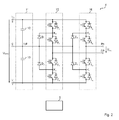
- FIG. 2 an example of a converter unit 4 is shown in the form of an H-bridge circuit.
- the H-bridge circuit has a capacitor intermediate circuit 11 to define a neutral node NP.
- the intermediate circuit 11 comprises a first capacitor 12, which is arranged between a high supply potential V H and the neutral node NP. Between the neutral node NP and a low supply potential V L , a second capacitor 13 is arranged.
- the voltage difference between the high and the low supply potential V H , V L corresponds to the supply voltage U verse .
- the converter unit 4 comprises a first inverter circuit 15 and a second inverter circuit 16, which are constructed essentially identical.
- the inverter circuits 15, 16 comprise as semiconductor switching elements four series-connected transistors T1, T2, T3, T4; T5, T6, T7, T8 whose control terminals are each controlled via the control unit 5 with corresponding control signals.
- the control unit 5 can switch on or open each of the power semiconductor switches T1 to T8 by means of suitable control signals and thus allow or prevent current flow.
- Each of the transistors T1 to T8 is provided with a reverse-biased freewheeling diode.
- a first node K 1 between the first power semiconductor switch T1 and the second power semiconductor switch T2 of the first inverter circuit 15 is connected to an anode terminal of a first diode D1.
- a cathode terminal of the first diode D1 is connected to the neutral node NP.
- a second node K 2 between the third power semiconductor switch T3 and the fourth power semiconductor switch T4 of the first inverter circuit 15 is connected to a cathode terminal of a second diode D2.
- An anode terminal of the second diode D2 is connected to the neutral node NP.
- a third node K 3 between the fifth power semiconductor switch T5 and the sixth power semiconductor switch T6 of the second inverter circuit 16 is connected to an anode terminal of a third diode D3 whose cathode terminal is connected to the neutral node NP. Accordingly, a cathode terminal of a fourth diode D4 to a fourth node K 4 between a seventh power semiconductor switch T7 and an eighth power semiconductor switch T8 is connected, wherein an anode terminal of the fourth diode D4 is connected to the neutral node NP.
- An output node between the sixth power semiconductor switch T6 and the seventh power semiconductor switch T7 of the second inverter circuit 16 corresponds to the phase output Ph of the converter unit 4 and an output node between the second Power semiconductor switch T2 and the third power semiconductor switch T3 of the first inverter circuit 15 a reference terminal CP of the converter unit 4th
- converter unit 4 is a five-stage converter, since the voltages U verse , U verse / 2, 0, -U verse / 2, -U verse can be provided as phase voltages with the aid of the potential of the intermediate circuit 11.
- the output phase voltage U P results as a difference between the phase connection Ph and the reference terminal CP.
- These phase voltages are subsequently encoded as 2, 1, 0, -1, -2 (corresponding to U verse , U verse / 2, 0, -U verse / 2, -U verse ).
- intermediate voltages ie the voltage states 1, 0, -1 by different switching states of the power semiconductor switches T1 to T8 of the converter unit 4. These switching states may affect a current flow (charge flow) to or from the neutral node NP, moving it away from its neutral point potential V NP .
- V L Since the neutral point potential V NP is usually approximately constant, ie within predetermined limits, remain and in particular a same or predefined voltage distance from the high and the low supply potential V H , V L should have, provide previous methods, the switching states in one Converter unit 4 for providing the voltage states 1, 0, -1 as a phase voltage to be output U P1 , U P2 , U P3 to be selected so that a charge balance between flowing to the neutral node NP and flowing from the neutral node NP flows is created.
- the switching states in one Converter unit 4 for providing the voltage states 1, 0, -1 as a phase voltage to be output U P1 , U P2 , U P3 to be selected so that a charge balance between flowing to the neutral node NP and flowing from the neutral node NP flows is created.
- the control unit 5 controls the power semiconductor switches T1 to T8 in accordance with a detected voltage vector, which is converted taking into account the redundancies to a suitable switching pattern for the control of the power semiconductor switches.
- a sequence of phase voltage vectors to be applied within a defined time window is determined as an optimal pulse pattern according to an optimization function.
- the optimized pulse pattern is determined according to a known method in order to achieve a predetermined optimization target. Examples of such optimization goals are the elimination of certain harmonics or the minimization of the distortion of the motor current.
- the optimized pulse pattern serves to model curves of the motor currents which correspond to the optimization target and to determine corresponding phase voltages with which the corresponding motor current can be achieved (frequently assuming a constant operating condition).
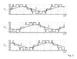
- phase voltages U P1 , U P2 , U P3 are output in order to obtain desired characteristics of the motor currents I 1 , I 2 , I 3 .
- FIG. 4 is a section of the diagram of FIG. 3 from which more clearly the individual phase voltages of the phase voltage vectors can be seen.
- each of the successive phase voltage vectors from the determined optimized pulse pattern is assigned one or more alternatives for phase difference voltage vectors indicating the phase-to-phase voltages between the phases.
- FIG. 5 1 shows a voltage vector hexagram with the possible phase difference voltage vectors for driving the synchronous motor 2.
- phase difference voltage vector For each possible phase difference voltage vector, one or more alternatives for combinations of phase voltages to be applied are indicated as redundant switching states of the converter circuit 4 relevant for the relevant phase difference voltage vector.
- a phase voltage vector of 201 indicated by the optimized pulse pattern may have a phase difference between the phase P1 and the phase difference Phase P2 of FIG. 2, between phase P1 and P3 of FIG.
- the redundancy single-phase redundancy for outputting a phase voltage at the output of each of the converter units 4 is added with a further redundancy at which the phase voltage can vary depending on the phase voltages of the other converter units 4 to output an equivalent phase voltage vector.
- the degree of freedom in the selection of phase voltage vectors for driving the synchronous motor 2 is significantly increased.
- FIG. 6 a hexagram is shown to illustrate a possible sequence of phase voltage vectors for the optimized pulse pattern.
- Each of the thick-rimmed circles represents a switching state predetermined by the pulse pattern.
- the switching states Z1 to Z4 each comprise a plurality of redundant phase voltage vectors, which can be arbitrarily combined with one another for applying the sequence of switching states, without the respective phase difference. Change voltages between the phases.
- Each of the individual switching states results in the output of a particular phase voltage at the output of each converter unit 4. It is noted that the realization of each switching state by a plurality of phase voltage vectors does not preclude the application of single-phase redundancy. This can further increase the number of possible redundant phase voltage vectors.
- FIG. 3 is a flow chart illustrating a method of operating the converter circuit.
- a step S1 according to an operating function, which may be described numerically or as a look-up table, the optimized pulse patterns which are to be created in a specific time window are read out.
- the Operating function determines the sequence of phase voltage vectors according to the optimized pulse pattern depending on operating state variables such as speed and load and motor current and the like.
- the optimized pulse pattern is determined according to a known method and is determined according to the achievement of a predetermined optimization target. Examples of such optimization goals are the elimination of certain harmonics or the minimization of the motor current.
- Each of the optimization targets can be converted into a desired course of the motor currents depending on the operating point.
- the sequence of the phase voltage vectors and their respective time duration within the defined time window is then modeled with the aid of a known model function, with which the desired course of the motor currents can be approximated as accurately as possible.
- the determination of the optimized switching patterns will not be discussed in more detail. It is only essential that the optimized pulse patterns are calculated in advance and a plurality of phase voltage vectors of the optimized pulse pattern to be applied within a predetermined time window (starting with the current time or a future time) are set.
- step S2 the phase difference voltage vector is determined in each case from the phase voltage vectors prescribed by the optimized pulse pattern which are to be applied to the motor connections, in particular during the next N switching operations or during a time window of predetermined duration.
- the voltage differences between the phase voltage given by the optimized pulse pattern of the first phase to the phase voltages of the second and third phases respectively given by the optimized pulse pattern and the voltage difference between the phase voltage of the second phase and the third voltage given by the optimized pulse pattern Phase calculated.
- These phase difference voltages define corresponding phase difference voltage vectors.
- step S3 for each phase difference voltage vector, the amount of redundant phase voltage vectors is determined which lead to the same phase difference voltages between the individual phases defined by the respective phase voltage vector.
- the amount is determined by adding further redundant phase voltage vectors to the considered phase voltage vector.
- the others redundant phase voltage vectors are determined by stepwise increasing and / or decreasing each of the phase voltages of the phase voltage vector under consideration by one voltage level and adding the resulting phase voltage vector as a redundant phase voltage vector to the set until a further increase or decrease in the considered phase voltages of the phase voltage vector becomes Exceeding or falling below the highest or the lowest of the converter circuit outputable voltage level leads.
- This results in a set of redundant switching state combinations as a product of the numbers of redundant phase voltage vectors for each switching state predetermined by the optimized pulse pattern.
- one or more additional redundant phase voltage vectors may be added, resulting in single phase redundancy from each previously determined redundant phase voltage vector.
- step S4 for each of the switching state combinations resulting from step S3, the effect on one or more internal electrical variables of the converter circuit 3 is determined via the N switching processes.
- the effects of each of the switching state combinations on the DC link potentials at the neutral node NP for each of the converter units 4, ie for each phase, according to the integral U 1 C ⁇ ⁇ T ⁇ 0 T ⁇ 1 ⁇ i t ⁇ dt determined.
- C is the effective capacitance of the DC link capacitors providing the DC link potential
- i is the (modeled) motor current of the corresponding phase.
- T0 corresponds to the start time of the sequence of phase voltage vectors indicated by the optimized pulse pattern, and T1 to the end time after application of the predetermined number of phase voltage vectors or after elapse of the predetermined time period.
- the time interval [T0, T1] can be divided into subintervals, the each corresponding to the period of time during which a particular phase voltage vector is applied. The integrations can then be performed separately and then the integration split results added.
- step S5 those switching sequences are selected from which the modeled DC link potential at the neutral node NP remains within predefined limits.
- step S6 an estimate of the switching losses is calculated for the sequences of phase voltage vectors selected in step S5, and in step S7 the switching sequence which causes the lowest switching losses is selected.
- the switching frequency or the common-mode voltage can also be considered in step S6, which can be optimized by selecting the most advantageous for operation in step S7.
- the sequence of phase voltage vectors may be selected so that the sum of the deviations of the internal magnitudes of the transducer units 4 from their reference values is minimized.
- step S8 the first phase voltage vector is applied to the motor terminals resulting from step S7.
- step S8 the next phase voltage vector of the switching sequence selected in step S7 is applied.
- step S7 the calculation of steps S1 to S7 is carried out again in order to determine a renewed optimized pulse pattern which is due to external influences, for example changes in rotational speed, load or motor currents may deviate from the previously calculated, to again select the optimal sequence of the phase voltage vector according to the steps S1 to S7.
- a plurality of the phase voltage vectors can be applied before a renewed determination of the optimal sequence according to steps S1 to S7 is carried out.
- Capacitances can be adjusted by expanding the set of available phase voltage vectors by further redundant phase voltage vectors (multiphase redundancies) and selecting them appropriately from the extended set of phase voltage vectors. Depending on the optimization objective, this can lead to a considerable reduction of the switching losses, since no additional switching operations have to be inserted in order to achieve the optimization objective (reduction of the fluctuation of the DC link potential, etc.).
- the above method can be applied to all multi-phase converter circuits.
- the above method is suitable for more than three-stage, in particular five-stage converter circuits.
- the above method of operating the converter circuit is advantageous in that the voltage pattern for operating the motor is not changed, whereby no effects on the harmonic content of the motor currents occur.
- the above method is predictive and therefore takes into account the switching restrictions of the converter circuit and serves to select an appropriate sequence of switching states to avoid non-possible transitions.
- the method is further very flexible and can be used to achieve various optimization goals, such as minimizing switching losses, switching frequency, common mode voltage, and the like. In particular, when minimizing the switching frequency and the switching losses, the method avoids the insertion of additional switching operations.
- two optimization goals can be pursued simultaneously. For example, as a first optimization target, the minimization of the switching frequency and, as a second optimization target, the minimization of the common-mode voltage can be achieved.
- a first of the further optimization functions can result in a plurality of phase voltage vectors which fulfill a corresponding first optimization target. From these multiple phase voltage vectors, the phase voltage vector can then be selected, which fulfills a second optimization target of a second of the several further optimization functions.
- the converter arrangement of the converter circuit 3 and the control unit 5 can also operate as a rectifier beyond.
- the phase outputs should in this case be controlled with phase voltage vectors such that they output a predetermined constant voltage, ie the voltage difference between the terminal voltages is constant, or a predetermined constant current.
Abstract
Description
Die Erfindung betrifft im Allgemeinen eine Wandleranordnung mit einem mehrstufigen Wandler zum Ansteuern von mehrphasigen Antrieben, insbesondere von Asynchronmaschinen, Synchronmaschinen und dergleichen. Die Erfindung betrifft weiterhin Verfahren zum Betreiben einer derartigen Wandlerschaltung.The invention generally relates to a converter arrangement with a multi-stage converter for driving multiphase drives, in particular asynchronous machines, synchronous machines and the like. The invention further relates to methods for operating such a converter circuit.
Zur Ansteuerung von mehrphasigen elektrisch kommutierten elektrischen Maschinen werden in der Regel mehrstufige Wandlerschaltungen vorgesehen. Die mehrstufigen Wandlerschaltungen umfassen in der Regel für jede Phase eine Wandlereinheit. Die Wandlereinheiten weisen jeweils mehrere Schaltelemente, insbesondere Leistungshalbleiterschalter, auf, die je nach momentanen Phasenspannungen bzw. Anschlussspannungen, die an eine angeschlossene elektrische Maschine ausgegeben werden sollen, gemäß einem bestimmten Schaltmuster für die Ansteuerung jedes der Schaltelemente angesteuert werden. Die Schaltmuster werden beispielsweise gemäß einen Konzept von optimierten Pulsmustern (OPP: optimized pulse pattern) ermittelt. Die optimierten Pulsmuster geben abhängig von dem momentanen Betriebszustand Phasenspannungspegel für jeden Ausgang der Wandlerschaltung für ein sich an den momentanen Zeitpunkt anschließendes Zeitfenster an, um einen gewünschten Verlauf der Ströme durch die Ausgänge der Wandleranordnung zu erreichen.For the control of multi-phase electrically commutated electrical machines multi-stage converter circuits are usually provided. The multi-stage converter circuits usually comprise a converter unit for each phase. The converter units each have a plurality of switching elements, in particular power semiconductor switches, which, depending on the instantaneous phase voltages or terminal voltages which are to be output to a connected electrical machine, are driven in accordance with a specific switching pattern for the control of each of the switching elements. The switching patterns are determined, for example, according to a concept of optimized pulse patterns (OPP: optimized pulse pattern). The optimized pulse patterns, depending on the current operating state, give phase voltage levels for each output of the converter circuit to current time subsequent time window to achieve a desired course of the currents through the outputs of the transducer assembly.
Die optimierten Pulsmuster werden so bestimmt, dass sie ein bestimmtes Optimierungsziel bei dem Betrieb der elektrischen Maschine erfüllen. Mögliche Optimierungsziele können beispielsweise die Eliminierung von bestimmten Oberschwingungen, die Minimierung des gesamten Oberschwingungsgehalts, die Minimierung eines Motorstroms bei vorgegebener Drehzahl der elektrischen Maschine und dergleichen sein.The optimized pulse patterns are determined so that they fulfill a specific optimization target in the operation of the electric machine. Possible optimization targets may be, for example, the elimination of certain harmonics, the minimization of the total harmonic content, the minimization of a motor current at a given rotational speed of the electrical machine, and the like.
Bei über eine Versorgungsgleichspannung versorgten, mehrstufigen Wandlerschaltungen werden in der Regel interne Zwischenspannungen generiert, die bei Bedarf den extern angelegten Versorgungspotenzialen hinzu addiert oder subtrahiert werden, um einen zwischen den Versorgungspotenzialen liegenden Phasenspannungspegel (Potenzial) zu erhalten. Konstruktionsbedingt können diese Phasenspannungen bei derartigen Wandlerschaltungen durch verschiedene Schaltzustände erreicht werden (Einzelphasenredundanzen), die Zwischenkreispotenziale und/oder Kondensatorspannungen über interne Kondensatoren der Wandlerschaltungen in unterschiedlicher Weise belasten.In the case of multistage converter circuits supplied via a DC supply voltage, internal intermediate voltages are generally generated which, if required, are added or subtracted from the externally applied supply potentials in order to obtain a phase voltage level (potential) lying between the supply potentials. By design, these phase voltages can be achieved in such converter circuits by different switching states (single-phase redundancies), the DC link potentials and / or capacitor voltages via internal capacitors load the converter circuits in a different way.
Wenn die optimierten Pulsmuster für den Betrieb der mehrstufigen Wandlerschaltung vorgesehen sind, besteht ein Problem darin, aus den durch die optimierten Pulsmuster bestimmten Phasenspannungen die tatsächlichen Schaltzustände für die Schaltelemente der Wandlerschaltung festzulegen, so dass zum einen die erforderlichen Phasenspannungen bereitgestellt werden und zum anderen die internen Zwischenkreispotenziale und - spannungen der Wandlerschaltung näherungsweise konstant oder innerhalb vorbestimmter Grenzen gehalten werden. Mit anderen Worten müssen bei der Ansteuerung des mehrstufigen Wandlers einerseits die oben beschriebenen Optimierungsziele erreicht werden und andererseits die internen Zwischenkreispotenziale und -spannungen näherungsweise konstant bzw. innerhalb der vorgegebenen Grenzen gehalten werden.If the optimized pulse patterns are provided for the operation of the multi-stage converter circuit, there is a problem in determining the actual switching states for the switching elements of the converter circuit from the phase voltages determined by the optimized pulse patterns, so that on the one hand the required phase voltages are provided and on the other hand the internal ones DC link potentials and voltages of the converter circuit are kept approximately constant or within predetermined limits. In other words, when controlling the multistage converter, on the one hand, the optimization goals described above must be achieved and, on the other hand, the internal DC link potentials and voltages must be kept approximately constant or within the prescribed limits.
Bisherige Lösungen zum Einstellen der internen Zwischenkreispotentiale und -spannungen in einer Wandlerschaltung beruhen auf der Nutzung dieser Einzelphasenredundanzen, die in der Regel durch Anwendung einer hysteresebasierten Steuerung bzw. Regelung durchgeführt werden. Das bedeutet, dass, wenn beispielsweise ein Zwischenkreispotenzial oder eine Spannung über einer schwebenden Kapazität einen bestimmten Grenzwert erreicht, eine entsprechende Regelung zwischen den entsprechenden Einzelphasenredundanzen umschaltet, um die Spannung in die gewünschte Richtung zu treiben. Mit anderen Worten werden negative und positive Kondensatorströme in geeigneter Weise hervorgerufen, so dass sich die Ladungsflüsse zu und von dem Kondensator ausgleichen (siehe
Ein in der Druckschrift
Gemäß einem weiteren Verfahren, das in der Druckschrift
Darüber hinaus kann je nach Betriebszustand der elektrischen Maschine bzw. einer durch ein optimiertes Pulsmuster vorgegebener Verlauf der Phasenspannungen die durch die Redundanz vorgegebenen möglichen Schaltzustände zum Einstellen der Phasenspannungen durch verschiedene Schaltmuster unter Umständen nicht ausreichend sein, um das Zwischenkreispotenzial an dem neutralen Punkt in der Wandlerschaltung in optimaler Weise konstant zu halten bzw. auf ein vorbestimmtes Potential zu regeln. Dies kann unter Umständen dazu führen, dass sich die internen Spannungen, wie beispielsweise Zwischenkreispotentiale und Kondensatorspannungen, von dem Sollwert wegbewegen, was zu einem gestörten Betrieb der elektrischen Maschine und insbesondere zur Erzeugung von unerwünschten Oberschwingungen führt. Weiterhin kann sich als Folge eines schwankenden Zwischenkreispotentials die Spannungsbelastung der Schaltelemente erhöhen und die Zwischenkreiskapazitäten beschädigt werden.In addition, depending on the operating state of the electrical machine or a predetermined by an optimized pulse pattern course of the phase voltages given by the redundancy possible switching states for adjusting the phase voltages by different switching patterns may not be sufficient to the DC link potential at the neutral point in the converter circuit optimally constant or to regulate to a predetermined potential. Under certain circumstances, this can lead to the internal voltages, such as, for example, intermediate circuit potentials and capacitor voltages, moving away from the desired value, which leads to faulty operation of the electrical machine and, in particular, to generation of undesirable harmonics. Furthermore, as a result of a fluctuating DC link potential, the voltage load of the switching elements may increase and the DC link capacitances may be damaged.
Erhöht man die Zahl der Pegel der Wandlerschaltung, so können sich oben genannte Effekte verstärken. Es ist daher wünschenswert, eine Wandlerschaltung und ein Verfahren zum Betreiben einer solchen Wandlerschaltung zur Verfügung zu stellen, bei dem die Abweichungen von internen Potenzialen und Spannungen ausgeglichen werden können, ohne zusätzliche Schaltvorgänge, die die Schaltverluste erhöhen, hervorzurufen und/oder ohne den Grad der Verzerrung durch Oberschwingungen zu erhöhen.If one increases the number of levels of the converter circuit, the above-mentioned effects can be amplified. It is therefore desirable to provide a converter circuit and a method for operating such a converter circuit, in which the deviations from internal potentials and voltages can be compensated for, without causing additional switching operations which increase the switching losses and / or without the degree of Increase distortion due to harmonics.
Es ist Aufgabe der vorliegenden Erfindung, ein Verfahren zum Betreiben eines mehrstufigen Wandlers zum Ansteuern einer elektrischen Maschine zur Verfügung zu stellen, mit dem es möglich ist, bei verschiedenen Betriebszuständen des Motorsystems zuverlässiger ein Konstanthalten bzw. Einstellen von internen Spannungen und Potentialen der Wandlerschaltung zu gewährleisten.It is an object of the present invention to provide a method for operating a multi-stage converter for driving an electric machine, with which it is possible to more reliably ensure a constant or setting of internal voltages and potentials of the converter circuit at different operating states of the motor system ,
Diese Aufgabe wird durch das Verfahren zum Betreiben einer mehrphasigen, mehrstufigen Wandlerschaltung gemäß Anspruch 1 sowie durch die Wandleranordnung, das Motorsystem und den Gleichrichter gemäß den nebengeordneten Ansprüchen gelöst.This object is achieved by the method for operating a multi-phase, multi-stage converter circuit according to
Weitere vorteilhafte Ausgestaltungen sind in den abhängigen Ansprüchen angegeben. Gemäß einem ersten Aspekt ist ein Verfahren zum Betreiben einer mehrphasigen, mehrstufigen Wandlerschaltung, insbesondere zum Betreiben einer mehrphasigen elektrischen Maschine oder eines Gleichrichters vorgesehen, wobei die Wandlerschaltung abhängig von internen Schaltzuständen mehrere Anschlussspannungen bereitstellt und ausgebildet ist, dass ein interner Zustand der Wandlerschaltung von einem Schaltzustand abhängt. Das Verfahren umfasst die folgenden Schritte:
- a) Bereitstellen einer zeitlichen Abfolge von Phasenspannungsvektoren gemäß einer Optimierungsfunktion für einen momentanen Zeitpunkt, wobei die Phasenspannungsvektoren der Abfolge jeweils für ein bestimmtes Zeitfenster die mehreren von der Wandlerschaltung bereitzustellenden Anschlussspannungen angeben,
- b) Ermitteln für mindestens einen der Phasenspannungsvektoren der Abfolge der Phasenspannungsvektoren eine Menge von einem oder mehreren redundanten Phasenspannungsvektoren, die die gleichen Spannungsdifferenzen zwischen den einzelnen Phasen aufweisen wie der mindestens eine Phasenspannungsvektor der Abfolge der Phasenspannungsvektoren, so dass sich mehrere redundante Abfolgen von Phasenspannungsvektoren ergeben, bei denen der mindestens eine der Phasenspannungsvektoren der Abfolge der Phasenspannungsvektoren durch einen der redundanten Phasenspannungsvektoren ersetzt ist;
- c) Auswählen von einer der redundanten Abfolgen von Phasenspannungsvektoren gemäß einer weiteren Optimierungsfunktion zum Optimieren des internen Zustands der Wandlerschaltung gemäß einem vorgegebenen Optimierungsziel; und
- d) Bereitstellen von mindestens des ersten Phasenspannungsvektors der ausgewählten Abfolge von Phasenspannungsvektoren zum Ansteuern der Wandlerschaltung.
- a) providing a time sequence of phase voltage vectors according to an optimization function for a current time, wherein the phase voltage vectors of the sequence indicate for each particular time window the plurality of terminal voltages to be provided by the converter circuit,
- b) determining for at least one of the phase voltage vectors of the sequence of phase voltage vectors a set of one or more redundant phase voltage vectors having the same voltage differences between the individual phases as the at least one phase voltage vector of the sequence of phase voltage vectors, resulting in a plurality of redundant sequences of phase voltage vectors, wherein the at least one of the phase voltage vectors of the sequence of phase voltage vectors is replaced by one of the redundant phase voltage vectors;
- c) selecting one of the redundant sequences of phase voltage vectors according to another optimization function for optimizing the internal state of the converter circuit according to a predetermined optimization target; and
- d) providing at least the first phase voltage vector of the selected sequence of phase voltage vectors for driving the converter circuit.
Eine Idee des obigen Verfahrens besteht darin, tatsächlich auszugebende Anschlussspannungen unter Inkaufnahme von Schwankungen der Gleichtaktspannung bei Vorgabe einer gemäß einer Optimierungsfunktion bereitgestellten Abfolge von Phasenspannungsvektoren zu bestimmen. Die Optimierungsfunktion kann die bereitgestellte Abfolge von Phasenspannungsvektoren abhängig von einem Motorstrom, Motordrehzahl und/oder einer wandlerinternen Spannung ermitteln. Dazu können aus den auszugebenden Phasenspannungsvektoren Phasendifferenz-Spannungsvektoren jeweils als Menge von Phasen-zu-Phasen-Spannungen ermittelt. Die Phasendifferenz-Spannungsvektoren geben jeweils die Spannungsdifferenzen zwischen den Wandlerausgängen zu einem bestimmten Zeitpunkt an. Diese Phasendifferenz-Spannungsvektoren können durch verschiedene Kombinationen der Anschlussspannungen realisiert werden und bilden somit eine Redundanz, da jedem der Phasendifferenz-Spannungsvektoren eine oder mehrere redundante Phasenspannungsvektoren zugeordnet sind. Somit werden mindestens einem der anfänglich durch die Abfolge der Phasenspannungsvektoren bereitgestellten Phasenspannungsvektoren eine Menge von einem oder mehreren redundanten Phasenspannungsvektoren bereitgestellt. Aus den sich daraus ergebenden redundanten Abfolgen von Phasenspannungsvektoren wird dann diejenige ausgewählt, durch die sich gemäß einem weiteren Optimierungsziel eine Optimierung eines Merkmals erreichen lässt.One idea of the above method is to determine actual terminal voltages to be output by accepting variations of the common-mode voltage when specifying a sequence of phase voltage vectors provided according to an optimization function. The optimization function may determine the provided sequence of phase voltage vectors depending on a motor current, motor speed, and / or a transformer internal voltage. For this purpose, phase difference voltage vectors can be determined in each case as a set of phase-to-phase voltages from the phase voltage vectors to be output. The phase difference voltage vectors each indicate the voltage differences between the transducer outputs at a particular time. These phase difference voltage vectors can be realized by different combinations of the terminal voltages and thus form a redundancy since each of the phase difference voltage vectors is associated with one or more redundant phase voltage vectors. Thus, at least one of the phase voltage vectors initially provided by the sequence of phase voltage vectors provides a set of one or more redundant phase voltage vectors. From the resulting redundant sequences of phase voltage vectors, the one is selected by which, according to a further optimization target, an optimization of a feature can be achieved.
Durch die Umwandlung der vorgegebenen Abfolge von Phasenspannungsvektoren in Phasendifferenz-Spannungsvektoren wird die darin enthaltene Gleichtaktspannungsvorgabe eliminiert, ohne den Spannungsbezug der Phasen zueinander aufzulösen. Dies ist möglich, da alle elektrischen Größen (abgesehen von der Gleichtakt-Spannung) der elektrischen Maschine von den Phasendifferenz-Spannungen abhängen, anstatt von den tatsächlich anliegenden absoluten Anschlussspannungen (Potenziale an den Wandlerausgängen), so dass die Anzahl der redundanten Schaltzustände, aus denen ausgewählt werden kann, im Vergleich zur eingangs beschrieben Einzelphasenredundanz deutlich erhöht ist.By converting the predetermined sequence of phase voltage vectors into phase difference voltage vectors, the common-mode voltage specification contained therein is eliminated without dissolving the voltage reference of the phases to one another. This is possible because all electrical quantities (apart from the common mode voltage) of the electric machine depend on the phase difference voltages instead of the actual applied absolute terminal voltages (potentials at the converter outputs), so that the number of redundant switching states from which can be selected, in comparison to the above-described single-phase redundancy is significantly increased.
Die Verwendung von Mehrfachphasenredundanzen anstelle oder zusätzlich zu den Einzelphasenredundanzen basiert auf der Beobachtung, dass der Motorstrom und insgesamt das Betriebsverhalten der elektrischen Maschine lediglich von den angelegten Phasendifferenzspannungen, d.h. der Differenzspannungen zwischen den Phasen, abhängt, so dass sich zum Bereitstellen eines bestimmten Spannungsvektors mit gleichen Phasendifferenz-Spannungen mehrere Phasenspannungskombinationen ergeben. Die Auswahl einer der Phasenspannungskombinationen aus den mehreren Phasenspannungskombinationen kann das Ziel des Einstellens von internen Potentialen und Spannungen an der Wandlerschaltung in verbesserter Weise durch die Nutzung einer größeren Zahl von Freiheitsgraden erreicht werden.The use of multi-phase redundancies instead of or in addition to the single phase redundancies is based on the observation that the motor current and overall operating behavior of the electric machine depends only on the applied phase difference voltages, ie the differential voltages between the phases. such that multiple phase voltage combinations result to provide a particular voltage vector with equal phase difference voltages. By selecting one of the phase voltage combinations from the plurality of phase voltage combinations, the goal of adjusting internal potentials and voltages at the converter circuit can be achieved in an improved manner by the use of a greater number of degrees of freedom.
Weiterhin kann die Abfolge von Phasenspannungsvektoren gemäß dem optimierten Pulsmuster eine Anzahl N von aufeinander folgenden Phasenspannungsvektoren angeben, wobei das Ansteuern der Wandlerschaltung so erfolgt, dass eine Anzahl von aufeinander folgenden Phasenspannungsvektoren ausgegeben wird, die kleiner ist als die Anzahl N der Phasenspannungsvektoren der Abfolge von Phasenspannungsvektoren, bevor eine erneute Ermittlung einer Abfolge von Phasenspannungsvektoren gemäß den Schritten a) bis c) durchgeführt wird.Furthermore, the sequence of phase voltage vectors according to the optimized pulse pattern may indicate a number N of successive phase voltage vectors, the driving of the converter circuit being such as to output a number of successive phase voltage vectors smaller than the number N of the phase voltage vectors of the sequence of phase voltage vectors before re-determining a sequence of phase voltage vectors according to steps a) to c).
Gemäß einer Ausführungsform kann die Optimierungsfunktion als Optimierungsziel die Reduzierung des Oberschwingungsgehalts der Motorströme oder die Reduzierung der Motorströme bei vorgegebener Drehzahl haben.According to one embodiment, the optimization function may have as an optimization target the reduction of the harmonic content of the motor currents or the reduction of the motor currents at a predetermined speed.
Weiterhin kann das Ermitteln der Menge des einen oder der mehreren redundanten Phasenspannungsvektoren durchgeführt werden, indem dem mindestens einen Phasenspannungsvektor der Abfolge der Phasenspannungsvektoren diejenigen Phasenspannungsvektoren hinzugefügt werden, die sich durch schrittweises Erhöhen und/oder Erniedrigen aller Anschlussspannungen des mindestens einen Phasenspannungsvektors um jeweils ein Spannungsniveau ergeben, solange bis eine weitere Erhöhung oder Erniedrigung der Anschlussspannungen zu einem Überschreiten bzw. einem Unterschreiten des höchsten bzw. des niedrigsten von der Wandlerschaltung ausgebbaren Spannungspegels führt.Furthermore, determining the amount of the one or more redundant phase voltage vectors may be performed by adding to the at least one phase voltage vector the sequence of phase voltage vectors those phase voltage vectors resulting from incrementing and / or decrementing each of the terminal voltages of the at least one phase voltage vector by one voltage level until a further increase or decrease in the terminal voltages leads to exceeding or falling below the highest or the lowest voltage level that can be output by the converter circuit.
Gemäß einer Ausführungsform kann der interne Zustand einem Zwischenkreispotenzial eines Zwischenkreises der Wandlerschaltung entsprechen, wobei die weitere Optimierungsfunktion eines oder eine Kombination von mehreren der folgenden Optimierungsziele umfasst:
- das Zwischenkreispotenzial liegt innerhalb eines vorgegebenen Potenzialbereichs;
- die Schaltverluste beim Übergang zwischen den Phasenspannungsvektoren der Abfolge der Phasenspannungsvektoren ist minimal;
- die Schaltfrequenz beim Übergang zwischen den Phasenspannungsvektoren der Abfolge der Phasenspannungsvektoren ist minimal;
- die Gleichtaktspannung und/oder die Schwankung der Gleichtaktspannung sind minimal;
- die durchschnittlichen Abweichungen des internen Zustands von einem vorgegebenen Referenzzustand sind minimal.
- the DC link potential lies within a specified potential range;
- the switching losses at the transition between the phase voltage vectors of the sequence of phase voltage vectors is minimal;
- the switching frequency at the transition between the phase voltage vectors of the sequence of phase voltage vectors is minimal;
- the common mode voltage and / or the fluctuation of the common mode voltage are minimal;
- the average deviations of the internal state from a given reference state are minimal.
Gemäß einem weiteren Aspekt ist eine Wandleranordnung vorgesehen. Die Wandleranordnung umfasst:
- eine Wandlerschaltung zum Bereitstellen von Phasenspannungen (Anschlussspannungen) an die elektrische Maschine,
- eine Steuereinheit, die ausgebildet ist, um
- eine zeitlichen Abfolge von Phasenspannungsvektoren gemäß einer Optimierungsfunktion und abhängig von einem Betriebspunkt der elektrischen Maschine für einen momentanen Zeitpunkt bereitzustellen, wobei die Phasenspannungsvektoren der Abfolge jeweils für ein bestimmtes Zeitfenster die von der Wandlerschaltung bereitzustellenden Phasenspannungen für jede der Phasen angeben,
- um für mindestens einen der Phasenspannungsvektoren der Abfolge der Phasenspannungsvektoren eine Menge von einem oder mehreren redundanten Phasenspannungsvektoren zu ermitteln, die die gleichen Spannungsdifferenzen zwischen den einzelnen Phasen aufweisen wie der mindestens eine Phasenspannungsvektor der Abfolge der Phasenspannungsvektoren, so dass sich mehrere redundante Abfolgen von Phasenspannungsvektoren ergeben, bei denen der mindestens eine der Phasenspannungsvektoren der Abfolge der Phasenspannungsvektoren durch einen der redundanten Phasenspannungsvektoren ersetzt ist;
- um eine der redundanten Abfolgen von Phasenspannungsvektoren gemäß einer weiteren Optimierungsfunktion zum Optimieren des internen Zustands der Wandlerschaltung gemäß einem vorgegebenen Optimierungsziel auszuwählen;
- um die Wandlerschaltung zur Ausgabe von mindestens des ersten Phasenspannungsvektors der ausgewählten Abfolge von Phasenspannungsvektoren anzusteuern.
- a converter circuit for providing phase voltages (connection voltages) to the electrical machine,
- a control unit that is designed to
- provide a temporal sequence of phase voltage vectors according to an optimization function and dependent on an operating point of the electric machine for a current time, wherein the phase voltage vectors of the sequence indicate, for a particular time window, the phase voltages to be provided by the converter circuit for each of the phases,
- in order to determine, for at least one of the phase voltage vectors of the sequence of phase voltage vectors, an amount of one or more redundant phase voltage vectors having the same voltage differences between the individual phases as the at least one phase voltage vector of the sequence of phase voltage vectors, resulting in a plurality of redundant sequences of phase voltage vectors, wherein the at least one of the phase voltage vectors of the sequence of phase voltage vectors is replaced by one of the redundant phase voltage vectors;
- to select one of the redundant sequences of phase voltage vectors according to another optimization function for optimizing the internal state of the converter circuit according to a predetermined optimization target;
- to drive the converter circuit to output at least the first phase voltage vector of the selected sequence of phase voltage vectors.
Gemäß einem weiteren Aspekt ist ein Motorsystem vorgesehen, umfassend:
- eine mehrphasige elektrische Maschine;
- die obige Wandleranordnung,
- a multi-phase electric machine;
- the above converter arrangement,
Gemäß einem weiteren Aspekt ist ein Gleichrichter mit einer Wandleranordnung vorgesehen, wobei die Optimierungsfunktion so definiert ist, dass die Anschlussspannungen oder ein Ausgangsstrom konstant ist.According to a further aspect, a rectifier with a converter arrangement is provided, wherein the optimization function is defined such that the terminal voltages or an output current is constant.
Bevorzugte Ausführungsformen werden nachfolgend anhand der beigefügten Zeichnungen näher erläutert. Es zeigen:
Figur 1- eine schematische Darstellung eines Motorsystems mit einer dreiphasigen fünfstufigen Wandlerschaltung;
Figur 2- ein Schaltbild einer Wandlereinheit zum Bereitstellen einer Phasenspannung;
Figur 3- eine Darstellung der einzelnen Phasenspannungen für jede der drei Phasen, die zu gewünschten Verläufen der Motorströme führen;
- Figur 4
- eine detailliertere Darstellung von Schaltereignissen innerhalb eines ausgewählten Zeitfensters der Verläufe der Phasenspannungen der
Figur 3 ; Figur 5- eine Darstellung eines Spannungszeiger-Hexagramms von Phasenspannungsvektoren der fünfstufigen Wandlerschaltung mit redundanten Phasenspannungsvektoren, die zu gleichen Phasen-zu-Phasen-Spannungen an der zu betreibenden Synchronmaschine führen;
- Figur 6
- eine Darstellung einer möglichen Abfolge der Phasenspannungsvektoren, vorgegeben durch das optimierte Pulsmuster, in dem Spannungszeiger-Hexagramm;
- Figur 7
- ein Flussdiagramm zur Darstellung eines Verfahrens zum Betreiben einer Wandlerschaltung; und
- Figur 8
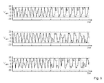
- ein Beispiel der Verläufe der Zwischenkreisspannungen ohne und mit Einsatz der prädiktiven Steuerung.
- FIG. 1
- a schematic representation of an engine system with a three-phase five-stage converter circuit;
- FIG. 2
- a circuit diagram of a converter unit for providing a phase voltage;
- FIG. 3
- a representation of the individual phase voltages for each of the three phases that lead to desired curves of the motor currents;
- FIG. 4
- a more detailed representation of switching events within a selected time window of the waveforms of the phase voltages
FIG. 3 ; - FIG. 5
- a representation of a voltage vector hexagram of phase voltage vectors of the five-stage converter circuit with redundant phase voltage vectors, which lead to equal phase-to-phase voltages at the synchronous machine to be operated;
- FIG. 6
- a representation of a possible sequence of the phase voltage vectors, given by the optimized pulse pattern, in the voltage vector hexagram;
- FIG. 7
- a flowchart illustrating a method for operating a converter circuit; and
- FIG. 8
- an example of the curves of the DC link voltages without and with the use of predictive control.
In
Am Eingang der Wandlerschaltung 3 liegt eine Versorgungsspannung UVers an. Diese Versorgungsspannung wird allen Wandlereinheiten 4 bereitgestellt. Die Wandlereinheiten 4 umfassen Halbleiterschaltelemente in Form von Thyristoren, IGBTs, IGCTs, Leistungs-MOSFETs und dergleichen und werden über eine Steuereinheit 5 angesteuert, so dass diese abhängig von der Ansteuerung geöffnet (nicht-leitend) oder geschlossen (leitend) werden. Die Leistungshalbleiterschalter jeder der Wandlereinheiten 4 werden gemäß einem Schaltmuster angesteuert, so dass die Wandlereinheiten 4 jeweils eine Phasenspannung UP1, UP2, UP3 auszugeben.At the input of the
In
Bei gleicher Auslegung der Kondensatoren 12, 13 stellt sich an dem neutralen Knoten NP ein Zwischenkreispotenzial ein, das mittig zwischen dem hohen und dem niedrigen Versorgungspotential VH, VL liegt. Zwischen dem hohen Versorgungspotential VH und dem neutralen Knoten NP liegt somit eine halbe Versorgungsspannung UVers/2 und zwischen dem neutralen Knoten NP und dem niedrigen Versorgungspotential VL ebenfalls die halbe Versorgungspotential UVers/2 an.With the same design of the
Des Weiteren umfasst die Wandlereinheit 4 eine erste Inverterschaltung 15 und eine zweite Inverterschaltung 16, die im Wesentlichen identisch aufgebaut sind. Die Inverterschaltungen 15, 16 umfassen als Halbleiterschaltelemente vier in Reihe zueinander geschaltete Transistoren T1, T2, T3, T4; T5, T6, T7, T8, deren Steueranschlüsse jeweils über die Steuereinheit 5 mit entsprechenden Steuersignalen angesteuert werden. Die Steuereinheit 5 kann durch geeignete Steuersignale jeden der Leistungshalbleiterschalter T1 bis T8 durchschalten oder öffnen und somit einen Stromfluss zulassen oder unterbinden. Jeder der Transistoren T1 bis T8 ist mit einer in Sperrrichtung gepolten Freilaufdiode versehen.Furthermore, the converter unit 4 comprises a
Weiterhin ist ein erster Knoten K1 zwischen dem ersten Leistungshalbleiterschalter T1 und dem zweiten Leistungshalbleiterschalter T2 der ersten Inverterschaltung 15 mit einem Anodenanschluss einer ersten Diode D1 verbunden. Ein Kathodenanschluss der ersten Diode D1 ist mit dem neutralen Knoten NP verbunden. Weiterhin ist ein zweiter Knoten K2 zwischen dem dritten Leistungshalbleiterschalter T3 und dem vierten Leistungshalbleiterschalter T4 der ersten Inverterschaltung 15 mit einem Kathodenanschluss einer zweiten Diode D2 verbunden. Ein Anodenanschluss der zweiten Diode D2 ist mit dem neutralen Knoten NP verbunden.Furthermore, a first node K 1 between the first power semiconductor switch T1 and the second power semiconductor switch T2 of the
Analog ist ein dritter Knoten K3 zwischen dem fünften Leistungshalbleiterschalter T5 und dem sechsten Leistungshalbleiterschalter T6 der zweiten Inverterschaltung 16 mit einem Anodenanschluss einer dritten Diode D3 verbunden, deren Kathodenanschluss mit dem neutralen Knoten NP verbunden ist. Entsprechend ist ein Kathodenanschluss einer vierten Diode D4 mit einem vierten Knoten K4 zwischen einem siebten Leistungshalbleiterschalter T7 und einem achten Leistungshalbleiterschalter T8 verbunden, wobei ein Anodenanschluss der vierten Diode D4 mit dem neutralen Knoten NP verbunden ist.Similarly, a third node K 3 between the fifth power semiconductor switch T5 and the sixth power semiconductor switch T6 of the
Ein Ausgangsknoten zwischen dem sechsten Leistungshalbleiterschalter T6 und dem siebten Leistungshalbleiterschalter T7 der zweiten Inverterschaltung 16 entspricht dem Phasenausgang Ph der Wandlereinheit 4 und ein Ausgangsknoten zwischen dem zweiten Leistungshalbleiterschalter T2 und dem dritten Leistungshalbleiterschalter T3 der ersten Inverterschaltung 15 einem Referenzanschluss CP der Wandlereinheit 4.An output node between the sixth power semiconductor switch T6 and the seventh power semiconductor switch T7 of the
Bei der in
Da das Neutralpunktpotential VNP in der Regel näherungsweise konstant , d.h. innerhalb vorgegebener Grenzen, bleiben soll und insbesondere einen gleichen bzw. vordefinierten Spannungsabstand von dem hohen und dem niedrigen Versorgungspotential VH, VL aufweisen soll, sehen bisherige Verfahren vor, die Schaltzustände in einer Wandlereinheit 4 zum Bereitstellen der Spannungszustände 1, 0, -1 als auszugebende Phasenspannung UP1, UP2, UP3 so auszuwählen, dass ein Ladungsausgleich zwischen auf den neutralen Knoten NP fließenden und von dem neutralen Knoten NP fließenden Strömen geschaffen wird. Je nach Ansteuerung des dreiphasigen Synchronmotors kann es jedoch bei bestimmten Betriebszuständen schwierig sein, das Neutralpunktpotential auf einem näherungsweise konstanten Pegel zu halten.Since the neutral point potential V NP is usually approximately constant, ie within predetermined limits, remain and in particular a same or predefined voltage distance from the high and the low supply potential V H , V L should have, provide previous methods, the switching states in one Converter unit 4 for providing the voltage states 1, 0, -1 as a phase voltage to be output U P1 , U P2 , U P3 to be selected so that a charge balance between flowing to the neutral node NP and flowing from the neutral node NP flows is created. Depending on the control of the three-phase synchronous motor, however, it may be difficult in certain operating conditions to keep the neutral point potential at an approximately constant level.
Die Steuereinheit 5 steuert die Leistungshalbleiterschalter T1 bis T8 gemäß einem ermittelten Spannungsvektor an, der unter Berücksichtigung der Redundanzen zu einem geeigneten Schaltmuster für die Ansteuerung der Leistungshalbleiterschalter umgesetzt wird. Abhängig von Betriebszuständen (Drehzahl, Last, Motorstrom, wandlerinterne Spannung usw.) wird gemäß einer Optimierungsfunktion eine Abfolge von innerhalb eines definierten Zeitfensters (beginnend mit dem momentanen Zeitpunkt oder mit einem künftigen Zeitpunkt) anzulegenden Phasenspannungsvektoren als optimales Pulsmuster bestimmt.The
Das optimierte Pulsmuster wird gemäß einem bekannten Verfahren ermittelt, um ein vorgegebenes Optimierungsziel zu erreichen. Beispiele für derartige Optimierungsziele sind die Eliminierung von bestimmten Oberschwingungen oder die Minimierung der Verzerrung des Motorstroms. Mit anderen Worten dient das optimierte Pulsmuster dazu, Verläufe der Motorströme zu modellieren, die dem Optimierungsziel entsprechen und entsprechende Phasenspannungen zu ermitteln, mit denen sich der entsprechende Motorstrom (häufig unter der Annahme einer konstanten Betriebsbedingung) erreichen lässt.The optimized pulse pattern is determined according to a known method in order to achieve a predetermined optimization target. Examples of such optimization goals are the elimination of certain harmonics or the minimization of the distortion of the motor current. In other words, the optimized pulse pattern serves to model curves of the motor currents which correspond to the optimization target and to determine corresponding phase voltages with which the corresponding motor current can be achieved (frequently assuming a constant operating condition).
Zum Erreichen von vordefinierten Phasenspannungen zum Ansteuern des Synchronmotors 2, wie sie beispielsweise in
Es hat sich herausgestellt, dass es für den Betrieb der elektrischen Maschine nicht so sehr auf die Pegel der Phasenspannungen ankommt, die durch die vorgegebenen Phasenspannungsvektoren definiert werden, sondern mehr auf die Spannungsdifferenzen zwischen den einzelnen Phasenanschlüssen P1, P2, P3 des Synchronmotors 2. Dadurch können weitere Freiheitsgrade für Optimierungen geschaffen werden, da es häufig möglich ist die gleichen Spannungsdifferenzvektoren mit verschiedenen Phasenspannungskombinationen zu realisieren. Damit ist es möglich, weitere redundante Zustände zu definieren, die man als Mehrphasenredundanzen bezeichnen kann. Es wird also jedem der aufeinanderfolgenden Phasenspannungsvektoren aus dem ermittelten optimierten Pulsmuster eine oder mehrere Alternativen für Phasendifferenz-Spannungsvektoren, die die Phasen-zu-Phasen-Spannungen zwischen den Phasen angeben, zugeordnet.It has been found that it does not depend so much on the level of the phase voltages defined by the given phase voltage vectors for the operation of the electrical machine, but more on the voltage differences between the individual phase terminals P1, P2, P3 of the
In
Man erkennt, dass bei den Schaltzuständen Z1 und Z4 jeweils drei verschiedene Phasenspannungsvektoren, die den geforderten Phasendifferenz-Spannungsvektor bereitstellen können, während die Schaltzustände Z2 und Z3 durch jeweils zwei Phasendifferenz-Spannungsvektoren bereitgestellt werden können. Man erkennt, dass 3 x 2 x 2 x 3 = 36 Kombinationen von Phasenspannungsvektoren möglich sind, um die durch das optimierte Pulsmuster geforderte Abfolge von Spannungszeigern an dem Synchronmotor 2 bereitzustellen. Jeder der einzelnen Schaltzustände führt zur Ausgabe einer bestimmten Phasenspannung am Ausgang jeder Wandlereinheit 4. Es wird angemerkt, dass die Realisierung jedes Schaltzustands durch mehrere Phasenspannungsvektoren die Anwendung der Einzelphasenredundanz nicht ausschließt. Dadurch kann sich die Anzahl der möglichen redundanten Phasenspannungsvektoren weiter erhöhen.It can be seen that each of the switching states Z1 and Z4 has three different phase voltage vectors which can provide the required phase difference voltage vector, while the switching states Z2 and Z3 can be provided by two phase difference voltage vectors in each case. It can be seen that 3 × 2 × 2 × 3 = 36 combinations of phase voltage vectors are possible in order to provide the sequence of voltage phasors on the
In
Das optimierte Pulsmuster wird gemäß einem bekannten Verfahren ermittelt und wird gemäß dem Erreichen eines vorgegebenen Optimierungsziels bestimmt. Beispiele für derartige Optimierungsziele sind die Eliminierung von bestimmten Oberschwingungen oder die Minimierung des Motorstroms. Jedes der Optimierungsziele lässt sich betriebspunktabhängig in einen Sollverlauf der Motorströme umsetzen. Es wird dann mit Hilfe einer an sich bekannten Modellfunktion die Abfolge der Phasenspannungsvektoren und deren jeweilige Zeitdauer innerhalb des definierten Zeitfensters modelliert, mit der der Sollverlauf der Motorströme möglichst genau angenähert werden kann. Im Folgenden soll auf die Ermittlung der optimierten Schaltmuster nicht näher eingegangen werden. Es ist lediglich wesentlich, dass die optimierten Pulsmuster im Vorfeld berechnet werden und mehrere innerhalb eines vorgegebenen Zeitfensters (beginnend mit dem momentanen Zeitpunkt oder einem zukünftigen Zeitpunkt) anzulegende Phasenspannungsvektoren des optimierten Pulsmusters festgelegt werden.The optimized pulse pattern is determined according to a known method and is determined according to the achievement of a predetermined optimization target. Examples of such optimization goals are the elimination of certain harmonics or the minimization of the motor current. Each of the optimization targets can be converted into a desired course of the motor currents depending on the operating point. The sequence of the phase voltage vectors and their respective time duration within the defined time window is then modeled with the aid of a known model function, with which the desired course of the motor currents can be approximated as accurately as possible. In the following, the determination of the optimized switching patterns will not be discussed in more detail. It is only essential that the optimized pulse patterns are calculated in advance and a plurality of phase voltage vectors of the optimized pulse pattern to be applied within a predetermined time window (starting with the current time or a future time) are set.
In Schritt S2 werden aus den durch das optimierte Pulsmuster vorgegebenen Phasenspannungsvektoren, die an die Motoranschlüsse angelegt werden sollen, jeweils der Phasendifferenz-Spannungsvektor ermittelt, insbesondere während der nächsten N Schaltvorgänge oder während eines Zeitfensters vorgegebener Dauer. Dazu werden bei oben dargestelltem Ausführungsbeispiel die Spannungsdifferenzen zwischen der durch das optimierte Pulsmuster vorgegebenen Phasenspannung der ersten Phase zu den jeweils durch das optimierte Pulsmuster vorgegebenen Phasenspannungen der zweiten und dritten Phase sowie die Spannungsdifferenz zwischen der durch das optimierte Pulsmuster vorgegebenen Phasenspannung der zweiten Phase und der dritten Phase errechnet. Diese Phasendifferenz-Spannungen definieren entsprechende Phasendifferenz-Spannungsvektoren.In step S2 the phase difference voltage vector is determined in each case from the phase voltage vectors prescribed by the optimized pulse pattern which are to be applied to the motor connections, in particular during the next N switching operations or during a time window of predetermined duration. For this purpose, in the exemplary embodiment shown above, the voltage differences between the phase voltage given by the optimized pulse pattern of the first phase to the phase voltages of the second and third phases respectively given by the optimized pulse pattern and the voltage difference between the phase voltage of the second phase and the third voltage given by the optimized pulse pattern Phase calculated. These phase difference voltages define corresponding phase difference voltage vectors.
In Schritt S3 wird für jeden Phasendifferenz-Spannungsvektor die Menge an redundanten Phasenspannungsvektoren ermittelt, die zu gleichen, durch den jeweiligen Phasenspannungsvektor definierten Phasendifferenzspannungen zwischen den einzelnen Phasen führen. Die Menge wird ermittelt, indem dem betrachteten Phasenspannungsvektor weitere redundante Phasenspannungsvektoren hinzugefügt werden. Die weiteren redundanten Phasenspannungsvektoren werden ermittelt, indem schrittweise alle Phasenspannungen des betrachteten Phasenspannungsvektors um jeweils ein Spannungsniveau erhöht und/oder erniedrigt werden und der sich daraus ergebende Phasenspannungsvektor als redundanter Phasenspannungsvektor der Menge hinzugefügt wird, solange bis eine weitere Erhöhung oder Erniedrigung der betrachteten Phasenspannungen des Phasenspannungsvektors zu einem Überschreiten bzw. einem Unterschreiten des höchsten bzw. des niedrigsten von der Wandlerschaltung ausgebbaren Spannungspegels führt. Daraus ergibt sich eine Menge an redundanten Schaltzustandskombinationen als Produkt der Anzahlen der redundanten Phasenspannungsvektoren zu jedem durch das optimierte Pulsmuster vorgegebenen Schaltzustand. Optional können ein oder mehrere weitere redundante Phasenspannungsvektoren hinzugefügt werden, die sich als Einzelphasenredundanz aus jedem zuvor ermittelten redundanten Phasenspannungsvektor ergeben.In step S3, for each phase difference voltage vector, the amount of redundant phase voltage vectors is determined which lead to the same phase difference voltages between the individual phases defined by the respective phase voltage vector. The amount is determined by adding further redundant phase voltage vectors to the considered phase voltage vector. The others redundant phase voltage vectors are determined by stepwise increasing and / or decreasing each of the phase voltages of the phase voltage vector under consideration by one voltage level and adding the resulting phase voltage vector as a redundant phase voltage vector to the set until a further increase or decrease in the considered phase voltages of the phase voltage vector becomes Exceeding or falling below the highest or the lowest of the converter circuit outputable voltage level leads. This results in a set of redundant switching state combinations as a product of the numbers of redundant phase voltage vectors for each switching state predetermined by the optimized pulse pattern. Optionally, one or more additional redundant phase voltage vectors may be added, resulting in single phase redundancy from each previously determined redundant phase voltage vector.
Nun wird in Schritt S4 für jede der sich aus Schritt S3 ergebenden Schaltzustandskombinationen über die N Schaltvorgänge die Auswirkung auf eine oder mehrere interne elektrische Größen der Wandlerschaltung 3 ermittelt. Im vorliegenden Ausführungsbeispiel werden die Auswirkungen jedes der Schaltzustandskombinationen auf die Zwischenkreispotenziale an den neutralen Knoten NP für jede der Wandlereinheiten 4, d.h. für jede Phase, gemäß dem Integral 
ermittelt. Dabei entsprechen C der wirksamen Kapazität der Kondensatoren des Zwischenkreises die die Zwischenkreispotenzial bereitstellen und i dem (modellierten) Motorstrom der entsprechenden Phase. Der Motorstrom wird berechnet unter Zuhilfenahme eines Modells des Synchronmotors 2. Alternativ kann unter der Annahme, dass der Motorstrom im Wesentlichen nur durch die Grundschwingung bestimmt wird, dieser mit i(t) = A*sin(w*t + p)
berechnet werden. Aus den Anfangsbedingungen können A und p berechnet und die obige Integration durchgeführt werden.Now, in step S4, for each of the switching state combinations resulting from step S3, the effect on one or more internal electrical variables of the
determined. Where C is the effective capacitance of the DC link capacitors providing the DC link potential and i is the (modeled) motor current of the corresponding phase. The motor current is calculated using a model of the
be calculated. From the initial conditions, A and p can be calculated and the above integration performed.
T0 entspricht dem Anfangszeitpunkt der durch das optimierte Pulsmuster angegebenen Abfolge von Phasenspannungsvektoren und T1 dem Endzeitpunkt nach dem Anlegen der vorbestimmten Anzahl der Phasenspannungsvektoren oder nach Ablauf der vorbestimmten Zeitperiode. Zur vereinfachten Integration kann das Zeitintervall [T0,T1] in Teilintervalle, die jeweils der Zeitdauer entsprechen, während der ein bestimmter Phasenspannungsvektor angelegt ist, unterteilt werden. Die Integrationen können dann separat durchgeführt und anschließend die Integrationsteilergebnisse addiert werden.T0 corresponds to the start time of the sequence of phase voltage vectors indicated by the optimized pulse pattern, and T1 to the end time after application of the predetermined number of phase voltage vectors or after elapse of the predetermined time period. For simplified integration, the time interval [T0, T1] can be divided into subintervals, the each corresponding to the period of time during which a particular phase voltage vector is applied. The integrations can then be performed separately and then the integration split results added.
In Schritt S5 werden aus allen Schaltfolgen diejenigen ausgewählt, bei denen das modellierte Zwischenkreispotenzial am neutralen Knoten NP innerhalb vorgegebener Grenzen bleibt.In step S5, those switching sequences are selected from which the modeled DC link potential at the neutral node NP remains within predefined limits.
In Schritt S6 wird für die in Schritt S5 ausgewählten Abfolgen der Phasenspannungsvektoren eine Schätzung der Schaltverluste errechnet und in Schritt S7 diejenige Schaltfolge ausgewählt, die die niedrigsten Schaltverluste bewirkt. Als alternatives Optimierungskriterium kommt in Schritt S6 auch die Schaltfrequenz oder die Gleichtaktspannung in Betracht, die optimiert werden kann, indem die für den Betrieb Vorteilhafteste in Schritt S7 ausgewählt wird. Bei dem Auswahlprozess des Schritts S7 kann es unter Umständen dazu kommen, dass sich mehrere Schaltfolgen als optimal herausstellen. In diesem Fall kann die Abfolge der Phasenspannungsvektoren so ausgewählt werden, dass die Summe der Abweichungen der internen Größen der Wandlereinheiten 4 von ihren Bezugsgrößen minimiert wird.In step S6, an estimate of the switching losses is calculated for the sequences of phase voltage vectors selected in step S5, and in step S7 the switching sequence which causes the lowest switching losses is selected. As an alternative optimization criterion, the switching frequency or the common-mode voltage can also be considered in step S6, which can be optimized by selecting the most advantageous for operation in step S7. In the selection process of step S7, under some circumstances it may happen that several switching sequences turn out to be optimal. In this case, the sequence of phase voltage vectors may be selected so that the sum of the deviations of the internal magnitudes of the transducer units 4 from their reference values is minimized.
In Schritt S8 wird der erste Phasenspannungsvektor an die Motoranschlüsse angelegt, der sich aus dem Schritt S7 ergibt. Bevor der nächste Phasenspannungsvektor der in Schritt S7 ausgewählten Schaltfolge angelegt wird, wird zunächst die Berechnung der Schritte S1 bis S7 erneut durchgeführt, um erneut für ein erneut bestimmtes optimiertes Pulsmuster, das sich aufgrund äußerer Einflüsse, beispielsweise Änderungen von Drehzahl, Last oder Motorströmen, von dem zuvor berechneten abweichen kann, erneut die optimale Abfolge der Phasenspannungsvektor gemäß der Schritte S1 bis S7 auszuwählen. Durch diese Vorgehensweise können Situationen vermieden werden, bei denen die zuvor angelegten Phasenspannungsvektoren zu einem Motorzustand geführt haben, von dem ausgehend sich das Optimierungsziel der weiteren Optimierungsfunktion nicht mehr erreichen lässt. Gemäß einer alternativen Ausführungsform können aus der in Schritt S7 bestimmten Abfolge von Phasenspannungsvektoren mehrere der Phasenspannungsvektoren angelegt werden, bevor eine erneute Ermittlung der optimalen Abfolge gemäß den Schritten S1 bis S7 durchgeführt wird.In step S8, the first phase voltage vector is applied to the motor terminals resulting from step S7. Before the next phase voltage vector of the switching sequence selected in step S7 is applied, first the calculation of steps S1 to S7 is carried out again in order to determine a renewed optimized pulse pattern which is due to external influences, for example changes in rotational speed, load or motor currents may deviate from the previously calculated, to again select the optimal sequence of the phase voltage vector according to the steps S1 to S7. By doing so, situations can be avoided in which the previously applied phase voltage vectors have led to an engine state, from which the optimization goal of the further optimization function can no longer be achieved. According to an alternative embodiment, from the sequence of phase voltage vectors determined in step S7, a plurality of the phase voltage vectors can be applied before a renewed determination of the optimal sequence according to steps S1 to S7 is carried out.
Im Ergebnis können mit dem obigen Verfahren interne, von Schaltzuständen abhängige Potenziale, wie z.B. die Zwischenkreispotenziale des neutralen Knotens NP, die durch Kapazitäten bereitgestellt werden, eingestellt werden, indem die Menge an verfügbaren Phasenspannungsvektoren durch weitere redundante Phasenspannungsvektoren (Mehrphasenredundanzen) erweitert und aus der erweiterten Menge an Phasenspannungsvektoren in geeigneter Weise ausgewählt werden. Dies kann je nach Optimierungsziel zu einer erheblichen Reduktion der Schaltverluste führen, da keine zusätzlichen Schaltvorgänge eingefügt werden müssen, um das Optimierungsziel (Reduzierung der Schwankung des Zwischenkreispotenzials usw.) zu erreichen.As a result, with the above method, internal, switching state dependent potentials, such as the DC link potentials of the neutral node NP, can be determined by Capacitances can be adjusted by expanding the set of available phase voltage vectors by further redundant phase voltage vectors (multiphase redundancies) and selecting them appropriately from the extended set of phase voltage vectors. Depending on the optimization objective, this can lead to a considerable reduction of the switching losses, since no additional switching operations have to be inserted in order to achieve the optimization objective (reduction of the fluctuation of the DC link potential, etc.).
Dies ist beispielsweise in dem Signal-Zeit-Diagramm der
Das obige Verfahren zum Betreiben der Wandlerschaltung ist vorteilhaft, da das Spannungsmuster zum Betreiben des Motors nicht verändert wird, wodurch keine Effekte auf den Oberschwingungsgehalt der Motorströme auftreten. Das obige Verfahren ist prädiktiv und berücksichtigt daher die Schaltbeschränkungen der Wandlerschaltung und dient zum Auswählen einer geeigneten Abfolge von Schaltzuständen, um nicht-mögliche bzw. nichtzulässige Übergänge zu vermeiden. Das Verfahren ist des Weiteren sehr flexibel und kann zum Erzielen verschiedener Optimierungsziele verwendet werden, wie beispielsweise die Minimierung von Schaltverlusten, der Schaltfrequenz, der Gleichtaktspannung und dergleichen. Insbesondere bei der Minimierung der Schaltfrequenz und der Schaltverluste vermeidet das Verfahren das Einfügen von zusätzlichen Schaltvorgängen. Insbesondere können gleichzeitig zwei Optimierungsziele verfolgt werden. Beispielsweise kann als ein erstes Optimierungsziel die Minimierung der Schaltfrequenz und als zweites Optimierungsziel die die Minimierung der Gleichtaktspannung erreicht werden.The above method of operating the converter circuit is advantageous in that the voltage pattern for operating the motor is not changed, whereby no effects on the harmonic content of the motor currents occur. The above method is predictive and therefore takes into account the switching restrictions of the converter circuit and serves to select an appropriate sequence of switching states to avoid non-possible transitions. The method is further very flexible and can be used to achieve various optimization goals, such as minimizing switching losses, switching frequency, common mode voltage, and the like. In particular, when minimizing the switching frequency and the switching losses, the method avoids the insertion of additional switching operations. In particular, two optimization goals can be pursued simultaneously. For example, as a first optimization target, the minimization of the switching frequency and, as a second optimization target, the minimization of the common-mode voltage can be achieved.
Es kann weiterhin vorgesehen sein, dass mehrere weitere Optimierungsfunktionen angewendet werden. So können sich aus einer ersten der weiteren Optimierungsfunktionen mehrere Phasenspannungsvektoren ergeben, die ein entsprechendes erstes Optimierungsziel erfüllen. Aus diesen mehreren Phasenspannungsvektoren kann dann der Phasenspannungsvektor ausgewählt werden, der ein zweites Optimierungsziel einer zweiten der mehreren weiteren Optimierungsfunktionen erfüllt.It can furthermore be provided that a plurality of further optimization functions are used. Thus, a first of the further optimization functions can result in a plurality of phase voltage vectors which fulfill a corresponding first optimization target. From these multiple phase voltage vectors, the phase voltage vector can then be selected, which fulfills a second optimization target of a second of the several further optimization functions.
Die Wandleranordnung aus der Wandlerschaltung 3 und der Steuereinheit 5 lässt sich darüber hinaus auch als Gleichrichter betreiben. Die Phasenausgänge sollten in diesem Fall mit Phasenspannungsvektoren so angesteuert werden, dass diese eine vorgegebene konstante Spannung, d.h. die Spannungsdifferenz zwischen den Anschlussspannungen sind konstant, bzw. einen vorgegebenen konstanten Strom ausgeben.The converter arrangement of the
- 11
- Motorsystemengine system
- 22
- Synchronmotorsynchronous motor
- 33
- Wandlerschaltungconverter circuit
- 44
- Wandlereinheitconverter unit
- 55
- Steuereinheitcontrol unit
- 1111
- ZwischenkreisDC
- 1212
- erster Kondensatorfirst capacitor
- 1313
- zweiter Kondensatorsecond capacitor
- 1515
- erste Inverterschaltungfirst inverter circuit
- 1616
- zweite Inverterschaltungsecond inverter circuit
- T1-T8T1-T8
- LeistungshalbleiterschalterPower semiconductor switch
- D1-D4D1-D4
- Diodendiodes
- UP1, UP2, UP3 U P1 , U P2 , U P3
- Phasenspannungenphase voltages
- PhPh
- Phasenanschlüssephase connections
- CPCP
- Referenzanschlüssereference connections
- UVers U verse
- Versorgungsspannungsupply voltage
- VH V H
- hohes Versorgungspotentialhigh supply potential
- VL V L
- niedriges Versorgungspotentiallow supply potential
Claims (8)
Priority Applications (11)
| Application Number | Priority Date | Filing Date | Title |
|---|---|---|---|
| EP10151549A EP2348627A1 (en) | 2010-01-25 | 2010-01-25 | Converter circuit and method for operating a multilevel converter circuit |
| RU2012136477/07A RU2551420C2 (en) | 2010-01-25 | 2010-12-22 | Electric converter control method |
| PCT/EP2010/070518 WO2011088949A2 (en) | 2010-01-25 | 2010-12-22 | Method for controlling an electrical converter |
| EP10796066A EP2529475A2 (en) | 2010-01-25 | 2010-12-22 | Model predictive control of multilevel converters |
| CA2798474A CA2798474A1 (en) | 2010-01-25 | 2010-12-22 | Method for controlling an electrical converter |
| BR112012018460A BR112012018460A2 (en) | 2010-01-25 | 2010-12-22 | method to control an electrical converter |
| CN2010800656877A CN102804583A (en) | 2010-01-25 | 2010-12-22 | Method for controlling an electrical converter |
| JP2012550349A JP2013519342A (en) | 2010-01-25 | 2010-12-22 | How to control an electrical converter |
| KR1020127022174A KR20120118047A (en) | 2010-01-25 | 2010-12-22 | Model predictive control of multilevel converters |
| AU2010343747A AU2010343747B9 (en) | 2010-01-25 | 2010-12-22 | Model predictive control of multilevel converters |
| US13/557,795 US8737103B2 (en) | 2010-01-25 | 2012-07-25 | Method and controller for controlling an electrical converter configured for generating an AC current for at least two phases |
Applications Claiming Priority (1)
| Application Number | Priority Date | Filing Date | Title |
|---|---|---|---|
| EP10151549A EP2348627A1 (en) | 2010-01-25 | 2010-01-25 | Converter circuit and method for operating a multilevel converter circuit |
Publications (1)
| Publication Number | Publication Date |
|---|---|
| EP2348627A1 true EP2348627A1 (en) | 2011-07-27 |
Family
ID=42536726
Family Applications (2)
| Application Number | Title | Priority Date | Filing Date |
|---|---|---|---|
| EP10151549A Withdrawn EP2348627A1 (en) | 2010-01-25 | 2010-01-25 | Converter circuit and method for operating a multilevel converter circuit |
| EP10796066A Withdrawn EP2529475A2 (en) | 2010-01-25 | 2010-12-22 | Model predictive control of multilevel converters |
Family Applications After (1)
| Application Number | Title | Priority Date | Filing Date |
|---|---|---|---|
| EP10796066A Withdrawn EP2529475A2 (en) | 2010-01-25 | 2010-12-22 | Model predictive control of multilevel converters |
Country Status (10)
| Country | Link |
|---|---|
| US (1) | US8737103B2 (en) |
| EP (2) | EP2348627A1 (en) |
| JP (1) | JP2013519342A (en) |
| KR (1) | KR20120118047A (en) |
| CN (1) | CN102804583A (en) |
| AU (1) | AU2010343747B9 (en) |
| BR (1) | BR112012018460A2 (en) |
| CA (1) | CA2798474A1 (en) |
| RU (1) | RU2551420C2 (en) |
| WO (1) | WO2011088949A2 (en) |
Cited By (3)
| Publication number | Priority date | Publication date | Assignee | Title |
|---|---|---|---|---|
| WO2014033155A1 (en) * | 2012-08-28 | 2014-03-06 | Abb Technology Ag | Controlling a modular converter in two stages |
| CN111538238A (en) * | 2020-03-25 | 2020-08-14 | 西安电子科技大学 | Method and system for switching sequence control and error analysis of first-order discrete switch |
| CN112542958A (en) * | 2019-09-20 | 2021-03-23 | 台达电子企业管理(上海)有限公司 | Control method and module for switching frequency of wind power converter and power generation system |
Families Citing this family (27)
| Publication number | Priority date | Publication date | Assignee | Title |
|---|---|---|---|---|
| CN102854797B (en) * | 2012-09-10 | 2015-11-18 | 广东电网公司电力科学研究院 | Fired power generating unit Dynamic matrix control multi-model switching method |
| US20150288287A1 (en) * | 2012-09-21 | 2015-10-08 | Aukland Uniservices Limited | Modular multi-level converters |
| EP2725706A1 (en) * | 2012-10-23 | 2014-04-30 | ABB Technology AG | Model predictive control with reference tracking |
| PT107079B (en) * | 2013-07-26 | 2015-11-20 | Inst Superior Técnico | CONTROL AND BALANCING PROCESS OF THE VOLTAGES IN THE CONDENSERS OF THE CONTINUOUS VOLTAGE DIVIDER OF MULTINABLE CONVERTERS WITH PREDICTIVE CONTROLLERS THROUGH INVERSE STABILIZED DYNAMICS AND WITH A SYSTEM IMPLEMENTING IT |
| US9479075B2 (en) | 2013-07-31 | 2016-10-25 | General Electric Company | Multilevel converter system |
| US9325273B2 (en) * | 2013-09-30 | 2016-04-26 | General Electric Company | Method and system for driving electric machines |
| KR101521546B1 (en) * | 2013-11-05 | 2015-05-28 | 한국전기연구원 | A modulation method of Modular multi level converter |
| WO2015102049A1 (en) * | 2014-01-06 | 2015-07-09 | 東芝三菱電機産業システム株式会社 | Electric power conversion system |
| DE102015104554A1 (en) * | 2014-05-16 | 2015-11-19 | Semikron Elektronik Gmbh & Co. Kg | circuitry |
| FI126063B (en) * | 2014-05-21 | 2016-06-15 | Vacon Oy | Limitation of electrical interference |
| US9555711B2 (en) * | 2014-06-03 | 2017-01-31 | Hamilton Sundstrand Corporation | Power converters |
| US9831812B2 (en) * | 2015-02-27 | 2017-11-28 | Nutech Ventures | Direct torque control of AC electric machines |
| CN106329950B (en) * | 2015-07-01 | 2019-01-08 | 南京南瑞继保电气有限公司 | Modularization multi-level converter driving signal modulator approach and failure separation method |
| FR3039940B1 (en) * | 2015-08-03 | 2017-08-11 | Inst Supergrid | VIRTUAL CAPACITY |
| WO2017083527A1 (en) | 2015-11-13 | 2017-05-18 | Marquette University | An on-line diagnostic method for switch faults in power converters |
| CN108780993B (en) * | 2015-11-13 | 2020-01-10 | 马凯特大学 | Fault-tolerant topological structure for multi-level T-type converter |
| US10459472B2 (en) * | 2015-12-07 | 2019-10-29 | Hamilton Sundstrand Corporation | Model predictive control optimization for power electronics |
| US10700526B2 (en) * | 2016-03-14 | 2020-06-30 | Ge Energy Power Conversion Technology Ltd. | Solar power converter with four-wire grid-side connection |
| RU168663U1 (en) * | 2016-08-19 | 2017-02-14 | Акционерное общество "Научно-исследовательский институт электронной техники" (АО "НИИЭТ) | CONTROLLER OF A WIDTH-PULSE CONTROL WITH A FIXED ON TIME |
| RU2669204C1 (en) * | 2017-06-07 | 2018-10-09 | Федеральное Государственное Бюджетное Образовательное Учреждение Высшего Образования "Новосибирский Государственный Технический Университет" | Single-phase multilevel converter in the electric energy generation system controlling method |
| DE102018125728B3 (en) * | 2018-10-17 | 2020-02-27 | Dr. Ing. H.C. F. Porsche Aktiengesellschaft | Method and system for parallel switching table optimization for multilevel converters |
| KR102091589B1 (en) * | 2019-02-18 | 2020-03-20 | 주식회사 효원파워텍 | Apparatus for reducing common mode voltage of system for controlling multi phase motor using interleaved |
| KR102374616B1 (en) * | 2019-08-02 | 2022-03-17 | 한국철도기술연구원 | Three-phase npc multilevel inverter |
| CN111030486B (en) * | 2019-12-06 | 2021-06-08 | 合肥工业大学 | Non-parameter finite set model prediction control method of three-level grid-connected inverter |
| US11515818B2 (en) * | 2020-03-25 | 2022-11-29 | King Fahd University Of Petroleum And Minerals | Common-mode voltage reduction of a SiC based dual T-type drive system |
| CN111682791B (en) * | 2020-06-23 | 2021-10-12 | 江苏师范大学 | Two-stage finite set model prediction control method |
| EP4080748A1 (en) * | 2021-04-19 | 2022-10-26 | ABB Schweiz AG | Method for controlling an energy conversion system, energy conversion system, controller, computer program, and computer-readable medium |
Citations (1)
| Publication number | Priority date | Publication date | Assignee | Title |
|---|---|---|---|---|
| EP2110939A1 (en) * | 2008-04-18 | 2009-10-21 | ABB Research LTD | Inverter and method for controlling an inverter with flying capacitors |
Family Cites Families (17)
| Publication number | Priority date | Publication date | Assignee | Title |
|---|---|---|---|---|
| JPH077960A (en) * | 1993-02-10 | 1995-01-10 | Mitsubishi Electric Corp | Pulse width modulation controlling method and pulse width modulation processing method |
| GB2285523B (en) * | 1994-01-08 | 1997-10-15 | Gec Alsthom Ltd | Improvements in or relating to multilevel convertors |
| JPH08107698A (en) * | 1994-10-04 | 1996-04-23 | Toyo Electric Mfg Co Ltd | Space vector pwm control method |
| JPH1023760A (en) * | 1996-07-04 | 1998-01-23 | Hitachi Ltd | Method for controlling voltage pwm converter |
| US6058031A (en) * | 1997-10-23 | 2000-05-02 | General Electric Company | Five level high power motor drive converter and control system |
| JP3841253B2 (en) * | 1999-08-12 | 2006-11-01 | 株式会社安川電機 | Neutral point potential control method for neutral point clamp inverter |
| US6700804B1 (en) * | 2000-11-02 | 2004-03-02 | American Superconductor Corporation | Integrated multi-level inverter assembly |
| JP3864308B2 (en) * | 2002-06-12 | 2006-12-27 | 株式会社安川電機 | PWM inverter control method |
| JP4556572B2 (en) * | 2004-09-09 | 2010-10-06 | アイシン・エィ・ダブリュ株式会社 | Electric drive control device, electric drive control method, and program |
| US7164254B2 (en) * | 2005-02-28 | 2007-01-16 | Rockwell Automation Technologies, Inc. | Modulation methods and apparatus for reducing common mode voltages |
| RU2289191C1 (en) * | 2005-10-04 | 2006-12-10 | Дмитрий Петрович Смирнов | Device and method for controlling frequency converter incorporating multilevel voltage inverter |
| RU2303851C1 (en) * | 2005-11-03 | 2007-07-27 | Аркадий Петрович Стригулин | Multilevel static frequency converter for feeding induction and synchronous motors |
| CN100525051C (en) * | 2006-07-27 | 2009-08-05 | 武汉大学 | Multiple level changing method and its used multiple level circuit |
| US7432683B2 (en) * | 2006-11-20 | 2008-10-07 | Gm Global Technology Operations, Inc. | PWM pattern sequence to reduce losses in voltage source inverters |
| US7839023B2 (en) * | 2007-07-18 | 2010-11-23 | Raytheon Company | Methods and apparatus for three-phase inverter with reduced energy storage |
| RU69353U1 (en) * | 2007-07-20 | 2007-12-10 | "Всероссийский научно-исследовательский, проектно-конструкторский и технологический институт релестроения с опытным производством" (ОАО "ВНИИР") | HIGH VOLTAGE FREQUENCY CONVERTER |
| US7990097B2 (en) * | 2008-09-29 | 2011-08-02 | Rockwell Automation Technologies, Inc. | Power conversion system and method for active damping of common mode resonance |
-
2010
- 2010-01-25 EP EP10151549A patent/EP2348627A1/en not_active Withdrawn
- 2010-12-22 WO PCT/EP2010/070518 patent/WO2011088949A2/en active Application Filing
- 2010-12-22 RU RU2012136477/07A patent/RU2551420C2/en not_active IP Right Cessation
- 2010-12-22 KR KR1020127022174A patent/KR20120118047A/en not_active Application Discontinuation
- 2010-12-22 BR BR112012018460A patent/BR112012018460A2/en not_active IP Right Cessation
- 2010-12-22 JP JP2012550349A patent/JP2013519342A/en active Pending
- 2010-12-22 CN CN2010800656877A patent/CN102804583A/en active Pending
- 2010-12-22 EP EP10796066A patent/EP2529475A2/en not_active Withdrawn
- 2010-12-22 AU AU2010343747A patent/AU2010343747B9/en not_active Ceased
- 2010-12-22 CA CA2798474A patent/CA2798474A1/en not_active Abandoned
-
2012
- 2012-07-25 US US13/557,795 patent/US8737103B2/en not_active Expired - Fee Related
Patent Citations (1)
| Publication number | Priority date | Publication date | Assignee | Title |
|---|---|---|---|---|
| EP2110939A1 (en) * | 2008-04-18 | 2009-10-21 | ABB Research LTD | Inverter and method for controlling an inverter with flying capacitors |
Non-Patent Citations (6)
| Title |
|---|
| F. FANG: "Multilevel PWM VSIs - Coordinated Control of Regenerative Three-Level Neutral Point Clamped Pulsewidth-Modulated Voltage Source Inverters", IEEE INDUSTRY APPLICATIONS MAGAZINE, 7000420, pages 51 - 58 |
| GEYER, T.; PAPAFOTIOU, G.; MORARI, M.;: "Model Predictive Direct Torque Control - Part I: Concept, Algorithm and Analysis", IEEE TRANSACTIONS ON INDUSTRIAL ELECTRONICS, vol. 56, no. 6, 5 June 2009 (2009-06-05), pages 1894 - 1905, XP002596525, ISSN: 0278-0046, DOI: 10.1109/TIE.2008.2007030 * |
| GEYER, T.; PAPAFOTIOU, G.;: "Model Predictive Direct Torque Control of a variable Speed Drive with a Five-Level Inverter", CONFERENCE PROCEEDINGS IECON '09 - 35TH ANNUAL CONFERENCE OF IEEE INDUSTRIAL ELECTRONICS, 2009, 3 November 2009 (2009-11-03) - 5 November 2009 (2009-11-05), pages 1203 - 1208, XP002596524, ISSN: 1553-572X, DOI: 10.1109/IECON.2009.5414663 * |
| J. POU; R. PINANDO ET AL.: "Evaluation of the Low-Frequency Neutral-Point Voltage Oscillations in the Three-Level Inverter", IEEE TRANSACTIONS ON INDUSTRIAL ELECTRONICS, vol. 52, no. 6, pages 1582 - 1588 |
| J. STEINKE: "Switching Frequency Optimal PWM Control of a Three-Level Inverter", IEEE TRANSACTIONS ON POWER ELECTRONICS, vol. 7, no. 3, 1070819, pages 487 - 496 |
| MARIO MARCHESONI ET AL: "Diode-Clamped Multilevel Converters: A Practicable Way to Balance DC-Link Voltages", IEEE TRANSACTIONS ON INDUSTRIAL ELECTRONICS, IEEE SERVICE CENTER, PISCATAWAY, NJ, USA, vol. 49, no. 4, 1 August 2002 (2002-08-01), XP011073743, ISSN: 0278-0046 * |
Cited By (7)
| Publication number | Priority date | Publication date | Assignee | Title |
|---|---|---|---|---|
| WO2014033155A1 (en) * | 2012-08-28 | 2014-03-06 | Abb Technology Ag | Controlling a modular converter in two stages |
| CN104584414A (en) * | 2012-08-28 | 2015-04-29 | Abb技术有限公司 | Controlling modular converter in two stages |
| CN104584414B (en) * | 2012-08-28 | 2016-10-26 | Abb技术有限公司 | Control the modular converter of two-stage |
| US9590530B2 (en) | 2012-08-28 | 2017-03-07 | Abb Schweiz Ag | Controlling a modular converter in two stages |
| CN112542958A (en) * | 2019-09-20 | 2021-03-23 | 台达电子企业管理(上海)有限公司 | Control method and module for switching frequency of wind power converter and power generation system |
| CN112542958B (en) * | 2019-09-20 | 2022-06-24 | 台达电子企业管理(上海)有限公司 | Control method and module for switching frequency of wind power converter and power generation system |
| CN111538238A (en) * | 2020-03-25 | 2020-08-14 | 西安电子科技大学 | Method and system for switching sequence control and error analysis of first-order discrete switch |
Also Published As
| Publication number | Publication date |
|---|---|
| CA2798474A1 (en) | 2011-07-28 |
| KR20120118047A (en) | 2012-10-25 |
| WO2011088949A2 (en) | 2011-07-28 |
| RU2551420C2 (en) | 2015-05-27 |
| US20130016549A1 (en) | 2013-01-17 |
| US8737103B2 (en) | 2014-05-27 |
| EP2529475A2 (en) | 2012-12-05 |
| CN102804583A (en) | 2012-11-28 |
| WO2011088949A3 (en) | 2012-03-08 |
| BR112012018460A2 (en) | 2016-04-12 |
| RU2012136477A (en) | 2014-03-10 |
| JP2013519342A (en) | 2013-05-23 |
| AU2010343747A1 (en) | 2012-08-23 |
| AU2010343747B9 (en) | 2014-07-03 |
| AU2010343747B2 (en) | 2014-06-26 |
Similar Documents
| Publication | Publication Date | Title |
|---|---|---|
| EP2348627A1 (en) | Converter circuit and method for operating a multilevel converter circuit | |
| EP3245727B1 (en) | Converter module for a multi-level energy converter | |
| DE102005028945A1 (en) | Motor driving device | |
| DE102017221085B4 (en) | Converter circuit | |
| DE112014003998T5 (en) | Inverter device | |
| DE112005000294T5 (en) | Motor driving device | |
| EP2110939A1 (en) | Inverter and method for controlling an inverter with flying capacitors | |
| DE102012220649A1 (en) | Power conversion device | |
| WO2014206704A1 (en) | Converter assembly having multi-step converters connected in parallel and method for controlling said multi-step converters | |
| EP3602762B1 (en) | Inverter | |
| EP2928060A1 (en) | Modular frequency converter circuit with submodules having different switching capacities | |
| EP2034606A1 (en) | Method for operating an electric rotary machine | |
| EP1513249B1 (en) | Method for neutral-point balancing of a three-level inverter | |
| DE102017115639A1 (en) | Reduction of ripple current during switching operations of a bridge circuit | |
| WO2014206696A1 (en) | Z-source inverter with optimized efficiency | |
| EP3095178B1 (en) | Modular power converter circuit with submodules which are operated in linear mode | |
| EP1748543B1 (en) | Method and apparatus for controlling an electrical machine | |
| WO2002025802A1 (en) | Arrangement and method for producing different output voltages with an alternating current generator | |
| CH660652A5 (en) | INVERTER ARRANGEMENT. | |
| EP2409394B1 (en) | Method for operating an inverter circuit and device for performing the method | |
| DE10215531A1 (en) | Inverter means | |
| DE102009028915A1 (en) | Controlling system for operating micro impact drive, particularly in motor vehicle, has actuating element for carrying out back and forth movement in dependence of controller with electrical controlling variable | |
| EP3556003B1 (en) | Multi-level converter and method for operating the same | |
| EP1298781B1 (en) | Power converter device and method for adjusting a variable DC voltage | |
| WO2024032998A1 (en) | Method for equalising the centre point voltage of a 3-level inverter |
Legal Events
| Date | Code | Title | Description |
|---|---|---|---|
| PUAI | Public reference made under article 153(3) epc to a published international application that has entered the european phase |
Free format text: ORIGINAL CODE: 0009012 |
|
| AK | Designated contracting states |
Kind code of ref document: A1 Designated state(s): AT BE BG CH CY CZ DE DK EE ES FI FR GB GR HR HU IE IS IT LI LT LU LV MC MK MT NL NO PL PT RO SE SI SK SM TR |
|
| AX | Request for extension of the european patent |
Extension state: AL BA RS |
|
| STAA | Information on the status of an ep patent application or granted ep patent |
Free format text: STATUS: THE APPLICATION IS DEEMED TO BE WITHDRAWN |
|
| 18D | Application deemed to be withdrawn |
Effective date: 20120128 |