EP2228895B1 - Inverter with utility grid interface - Google Patents
Inverter with utility grid interface Download PDFInfo
- Publication number
- EP2228895B1 EP2228895B1 EP20090003353 EP09003353A EP2228895B1 EP 2228895 B1 EP2228895 B1 EP 2228895B1 EP 20090003353 EP20090003353 EP 20090003353 EP 09003353 A EP09003353 A EP 09003353A EP 2228895 B1 EP2228895 B1 EP 2228895B1
- Authority
- EP
- European Patent Office
- Prior art keywords
- relay
- inverter
- circuit according
- inverter circuit
- bfs
- Prior art date
- Legal status (The legal status is an assumption and is not a legal conclusion. Google has not performed a legal analysis and makes no representation as to the accuracy of the status listed.)
- Active
Links
- 238000012360 testing method Methods 0.000 claims description 11
- 239000004020 conductor Substances 0.000 claims description 7
- 238000006243 chemical reaction Methods 0.000 claims description 3
- 230000004913 activation Effects 0.000 claims 5
- 239000003990 capacitor Substances 0.000 description 6
- 238000000926 separation method Methods 0.000 description 6
- 230000006870 function Effects 0.000 description 4
- 239000004065 semiconductor Substances 0.000 description 4
- 238000009434 installation Methods 0.000 description 2
- 238000002955 isolation Methods 0.000 description 2
- 238000012544 monitoring process Methods 0.000 description 2
- 230000007935 neutral effect Effects 0.000 description 2
- 230000009993 protective function Effects 0.000 description 2
- 238000013461 design Methods 0.000 description 1
- 238000001514 detection method Methods 0.000 description 1
- 238000011161 development Methods 0.000 description 1
- 230000008030 elimination Effects 0.000 description 1
- 238000003379 elimination reaction Methods 0.000 description 1
- 238000012840 feeding operation Methods 0.000 description 1
- 238000011990 functional testing Methods 0.000 description 1
- 238000012423 maintenance Methods 0.000 description 1
- 238000004519 manufacturing process Methods 0.000 description 1
- 238000005259 measurement Methods 0.000 description 1
- 238000012806 monitoring device Methods 0.000 description 1
Images

Classifications
-
- H—ELECTRICITY
- H02—GENERATION; CONVERSION OR DISTRIBUTION OF ELECTRIC POWER
- H02J—CIRCUIT ARRANGEMENTS OR SYSTEMS FOR SUPPLYING OR DISTRIBUTING ELECTRIC POWER; SYSTEMS FOR STORING ELECTRIC ENERGY
- H02J3/00—Circuit arrangements for ac mains or ac distribution networks
- H02J3/38—Arrangements for parallely feeding a single network by two or more generators, converters or transformers
- H02J3/40—Synchronising a generator for connection to a network or to another generator
-
- G—PHYSICS
- G01—MEASURING; TESTING
- G01R—MEASURING ELECTRIC VARIABLES; MEASURING MAGNETIC VARIABLES
- G01R31/00—Arrangements for testing electric properties; Arrangements for locating electric faults; Arrangements for electrical testing characterised by what is being tested not provided for elsewhere
- G01R31/327—Testing of circuit interrupters, switches or circuit-breakers
- G01R31/3277—Testing of circuit interrupters, switches or circuit-breakers of low voltage devices, e.g. domestic or industrial devices, such as motor protections, relays, rotation switches
-
- H—ELECTRICITY
- H01—ELECTRIC ELEMENTS
- H01H—ELECTRIC SWITCHES; RELAYS; SELECTORS; EMERGENCY PROTECTIVE DEVICES
- H01H47/00—Circuit arrangements not adapted to a particular application of the relay and designed to obtain desired operating characteristics or to provide energising current
- H01H47/002—Monitoring or fail-safe circuits
-
- H—ELECTRICITY
- H02—GENERATION; CONVERSION OR DISTRIBUTION OF ELECTRIC POWER
- H02J—CIRCUIT ARRANGEMENTS OR SYSTEMS FOR SUPPLYING OR DISTRIBUTING ELECTRIC POWER; SYSTEMS FOR STORING ELECTRIC ENERGY
- H02J7/00—Circuit arrangements for charging or depolarising batteries or for supplying loads from batteries
- H02J7/34—Parallel operation in networks using both storage and other dc sources, e.g. providing buffering
- H02J7/35—Parallel operation in networks using both storage and other dc sources, e.g. providing buffering with light sensitive cells
-
- H—ELECTRICITY
- H02—GENERATION; CONVERSION OR DISTRIBUTION OF ELECTRIC POWER
- H02M—APPARATUS FOR CONVERSION BETWEEN AC AND AC, BETWEEN AC AND DC, OR BETWEEN DC AND DC, AND FOR USE WITH MAINS OR SIMILAR POWER SUPPLY SYSTEMS; CONVERSION OF DC OR AC INPUT POWER INTO SURGE OUTPUT POWER; CONTROL OR REGULATION THEREOF
- H02M7/00—Conversion of ac power input into dc power output; Conversion of dc power input into ac power output
- H02M7/42—Conversion of dc power input into ac power output without possibility of reversal
- H02M7/44—Conversion of dc power input into ac power output without possibility of reversal by static converters
- H02M7/48—Conversion of dc power input into ac power output without possibility of reversal by static converters using discharge tubes with control electrode or semiconductor devices with control electrode
-
- H—ELECTRICITY
- H02—GENERATION; CONVERSION OR DISTRIBUTION OF ELECTRIC POWER
- H02S—GENERATION OF ELECTRIC POWER BY CONVERSION OF INFRARED RADIATION, VISIBLE LIGHT OR ULTRAVIOLET LIGHT, e.g. USING PHOTOVOLTAIC [PV] MODULES
- H02S40/00—Components or accessories in combination with PV modules, not provided for in groups H02S10/00 - H02S30/00
- H02S40/30—Electrical components
- H02S40/32—Electrical components comprising DC/AC inverter means associated with the PV module itself, e.g. AC modules
-
- Y—GENERAL TAGGING OF NEW TECHNOLOGICAL DEVELOPMENTS; GENERAL TAGGING OF CROSS-SECTIONAL TECHNOLOGIES SPANNING OVER SEVERAL SECTIONS OF THE IPC; TECHNICAL SUBJECTS COVERED BY FORMER USPC CROSS-REFERENCE ART COLLECTIONS [XRACs] AND DIGESTS
- Y02—TECHNOLOGIES OR APPLICATIONS FOR MITIGATION OR ADAPTATION AGAINST CLIMATE CHANGE
- Y02E—REDUCTION OF GREENHOUSE GAS [GHG] EMISSIONS, RELATED TO ENERGY GENERATION, TRANSMISSION OR DISTRIBUTION
- Y02E10/00—Energy generation through renewable energy sources
- Y02E10/50—Photovoltaic [PV] energy
Definitions
- the invention relates to an inverter circuit according to the preamble of claim 1.
- Inverters serve to convert a DC voltage to AC voltage and include a semiconductor bridge circuit that performs a DC-AC converter function.
- the DC voltage can be a DC voltage source such. B. be a battery. Frequently, the DC voltage source is a photovoltaic generator, which is to feed energy into a power grid.
- Photovoltaic inverters for installation in relatively small areas are designed to be as compact, handy and lightweight as possible, so that they can be mounted without much tooling.
- Such an inverter has a weight and dimensions that allow one or at most two people to transport and assemble the device substantially without tools.
- the required electronic components, semiconductors, filter chokes, capacitors and the like must be accommodated.
- the higher the permissible output power of the device the larger the components are dimensioned. That is, if the device is to be compact, this results in a tightly populated housing or device.
- photovoltaic inverters In order to be approved for grid-parallel infeed, however, photovoltaic inverters must have an automatic switching point to the grid in accordance with relevant standards and regulations (eg DIN V VDE V 0 1 2 6 - 1 - 1) whose main task is to prevent unintentional feed-in to the grid Sub-network or an island network exists and thus exercises a protective function.
- relevant standards and regulations eg DIN V VDE V 0 1 2 6 - 1 - 1 - 1
- Three-pole relays or contactors are only available for larger power ranges and require considerably greater space compared to solderable relays. Furthermore, their assembly is complicated, error-prone and not suitable for mass production. For a standard-compliant solution, therefore, six single-pole relays would have to be used, which is not only expensive, but also costs installation space.
- the invention has for its object to provide an inverter circuit, on the one hand allows a compact design of the inverter and on the other hand, however, meets the relevant standards.
- the present invention provides a circuit that enables a three-phase photovoltaic inverter to be compliant with standards, with only three two-pole relays, which is less expensive and more compact than a six-pole relay solution.
- the interconnection according to the invention of three two-pole relays also a large series suitable solution for the prescribed separation point is provided to the feed point, which can maintain their protective function despite a minimal use of components even in the event of a single fault.
- the relay circuit is designed as an automatic switching point to prevent inadvertent feed into a partial or island grid.
- the inverter can be disconnected from the failed grid so that the inverter voltage does not endanger persons during maintenance work.
- relay circuit is integrated in an inverter housing.
- the DC-AC converter and the separator form a unit.
- the housing dimensions must be changed only insignificantly by the small number of relays or can remain the same. It is also possible, the arrangement of the relay in an additional housing. A space-saving solution is realized when each relay is designed as a relay solderable on a circuit board (prinelay relay).
- a transformerless version of the inverter is not only lightweight and very compact, but allows through the relay galvanic isolation of a DC voltage generator. Overall, the inverter is very compact with only three relays and without a transformer.
- release points are used to allow standard-compliant grid-parallel feed operation of multiple inverters.
- Each inverter preferably has its own release point with three relays.
- each relay coil can be actuated by a control circuit of a control unit.
- the drive circuit can be designed as a relay driver circuit with controllable semiconductors such as transistors.
- the drive circuit for each relay coil comprises an AND gate, in which one gate input is connected to the drive circuit and another gate input is connected to a watchdog device, so that each relay coil only is actuated when both a set signal and an interrupt signal of the watchdog device are present simultaneously.
- the operational management (BFS) or the control unit is permanently monitored by the watchdog device.
- the relay contacts which are designed as NO can only be closed when both the control unit and the watchdog device send signals that are passed through the AND gate to the relay drive circuit. Since each relay has only one contact per phase, a single control signal does not yet lead to a galvanic connection between the inverter and the grid.
- the relay control signals are interrupted for sufficiently short times and evaluated the reactions at the control coils by a relay test signal from the control unit. Sufficiently short here means that within the elimination of the drive signal no mechanical reaction of the contact can take place, but electrically a functional test is possible.
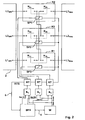
- FIG. 1 shows a photovoltaic inverter 1 with an inverter circuit for converting a photovoltaic DC voltage into a three-phase mains frequency AC voltage.
- the inverter comprises a full-bridge circuit 2 with six semiconductor switches and parallel freewheeling diodes, which form a DC / AC converter.
- a buffer capacitor C1 and a boost converter 3 with a throttle LH Between the boost converter two identical DC link capacitors C2, C3 are arranged in series, wherein at its node a voltage tap for voltages VR1, VR2 and VR3 takes place. These voltages are measured to monitor the operation of a separator.
- the tie point is used to define a neutral stress point.
- Between the separator and the DC / AC converter is still a filter, in particular with three filter inductors LN.
- FIG. 1 a arranged between the DC / AC converter and a power grid NE relay circuit, which is designed as a switching point 4 for galvanic isolation for active conductors L1, L2, L3.
- the relays R1 - R3 preferably have normally open contacts.
- the network NE is also provided with an N-conductor, wherein the conductor voltages VL1, VL2, VL3 against N are also measured for function monitoring.
- the relay circuit has only three two-pole relays R1, R2, R3 ( FIG. 2 ).
- Each relay R1, R2, R3 has a control coil Sp1, Sp2, Sp3 and two of the control coils Sp1, Sp2, Sp3 associated relay contacts K1 a, K1 b; K2a, K2b; K3a, K3b.
- the second switching contact K2b of the relay R2 associated with the phase L1 is connected in series with the first switching contact K1a of the first relay R1 (phase L1).
- the contacts K1a and K2b are in series. It is also possible that the contacts, z. B. K1 a and K3b, are in series, however, the contacts of the same relay, z. B. K1 a and K1 b, not in series.
- FIG. 1 the contacts of the different relays are shown graphically behind each other (eg K1 a with K2b).
- the relay coils Sp1 - Sp3 are each connected by relay drivers and driving circuits RT to an output of an AND gate.
- One of the inputs of the AND gate is connected to a control unit BFS (operational management) for the relays R1-R3 through a line which carries a set signal SET_K1, SET_K2 and SET_K3, respectively.
- the other AND input can be activated by a safety signal SAFE-BREAK of a watchdog device W.
- the watchdog device W is connected to the control unit BFS by a line 5, which can give a test signal CHECK.
- the relay drivers are also connected by the line 6 to the control unit BFS, wherein the line 6 can give a relay test signal RTS.
- Relay control signals are interrupted by the test signal RTS for such a short time at the relay drivers or the drive circuit RT that no contact separation takes place, the responses to the test signal RTS at the control coils Sp1, Sp2, Sp3 being evaluated by the control unit BFS. This will check the relay drivers.
- the function test is performed by voltage measurement of the voltages VR1 - VR3 and VL1 - VL3.
- the watchdog device W prevents the relays R1-R3 from closing. If the watchdog device W fails, the control unit BFS prevents the relays R1-R3 from closing. falls a logic gate (AND) off, the control unit BFS registers this error through the relay R1 - R3 test signals RTS.
- both relays will never be closed within one phase, even with a single fault.
- the invention is not limited to this example, so instead of a full bridge and a half-bridge, a different capacitor and filter arrangement (C1 - C3, LN), or another matching stage 3 can be selected.
- relay here includes any device comprising a control coil and mechanical switching contacts, including a contactor.
Description
Die Erfindung betrifft eine Wechselrichterschaltung nach dem Oberbegriff des Anspruches 1.The invention relates to an inverter circuit according to the preamble of
Wechselrichter dienen der Umwandlung einer Gleichspannung in Wechselspannung und umfassen eine aus Halbleitern bestehende Brückenschaltung, die eine DC-AC-Wandlerfunktion übernimmt.Inverters serve to convert a DC voltage to AC voltage and include a semiconductor bridge circuit that performs a DC-AC converter function.
Die Gleichspannung kann dabei eine Gleichspannungsquelle, wie z. B. eine Batterie sein. Häufig ist die Gleichspannungsquelle ein Photovoltaikgenerator, der Energie in ein Energieversorgungsnetz einspeisen soll.The DC voltage can be a DC voltage source such. B. be a battery. Frequently, the DC voltage source is a photovoltaic generator, which is to feed energy into a power grid.
Photovoltaikwechselrichter für die Installation auf relativ kleinen Flächen sollen eine möglichst kompakte, handliche und leichte Bauweise aufweisen, damit sie ohne großen Werkzeugaufwand montiert werden können. Ein solcher Wechselrichter besitzt ein Gewicht und Abmaße, die es erlauben, dass ein oder maximal zwei Personen das Gerät im Wesentlichen ohne Hilfsmittel transportieren und montieren können.Photovoltaic inverters for installation in relatively small areas are designed to be as compact, handy and lightweight as possible, so that they can be mounted without much tooling. Such an inverter has a weight and dimensions that allow one or at most two people to transport and assemble the device substantially without tools.
Innerhalb des Gehäuses müssen die erforderlichen elektronischen Komponenten, Halbleiter, Filterdrosseln, Kondensatoren und dergleichen untergebracht werden. Je höher die zulässige Ausgangsleistung des Gerätes ist, umso größer sind auch die Bauteile dimensioniert. Das heißt, wenn das Gerät kompakt sein soll, hat dies ein eng bestücktes Gehäuse bzw. Gerät zur Folge.Within the housing, the required electronic components, semiconductors, filter chokes, capacitors and the like must be accommodated. The higher the permissible output power of the device, the larger the components are dimensioned. That is, if the device is to be compact, this results in a tightly populated housing or device.
Für die Zulassung zur netzparallelen Einspeisung müssen Photovoltaikwechselrichter jedoch gemäß einschlägiger Normen und Vorschriften (z. B. DIN V VDE V 0 1 2 6 - 1 - 1) über eine selbsttätige Schaltstelle zum Netz verfügen, deren Hauptaufgabe in der Verhinderung einer unbeabsichtigten Einspeisung in ein Teilnetz bzw. ein Inselnetz besteht und die damit eine Schutzfunktion ausübt.In order to be approved for grid-parallel infeed, however, photovoltaic inverters must have an automatic switching point to the grid in accordance with relevant standards and regulations (eg DIN V VDE V 0 1 2 6 - 1 - 1) whose main task is to prevent unintentional feed-in to the grid Sub-network or an island network exists and thus exercises a protective function.
Um ein zusätzliches Gehäuse oder anderes zusätzliches Montagehilfsmittel zu sparen, ist bekannt, die Schaltstelle in das bereits vorhandene Wechselrichtergehäuse zu integrieren, was wiederum die Gehäuseabmessungen vergrößert.In order to save an additional housing or other additional mounting tool, it is known to integrate the switch in the existing inverter housing, which in turn increases the housing dimensions.
Zudem fordert die erwähnte Norm, dass diese Schaltstelle den Einspeisebetrieb pro aktiven Leiter durch zwei unabhängig voneinander zu betätigende, in Serie liegende Schalter unterbrechen muss. Des Weiteren muss die Trennung dergestalt aufgebaut sein, dass auch im Fall des Auftretens eines einzelnen Fehlers die Sicherheitsfunktion gewahrt bleibt.In addition, the mentioned standard requires that this switching point must interrupt the feeding operation per active conductor by two independently operable series-connected switches. Furthermore, the separation must be designed in such a way that the safety function is maintained even in the event of the occurrence of a single fault.
Gängige Praxis für die Erfüllung dieser Vorgaben ist es, bis zu einem Bereich mittlerer Leistungen von mehreren 10kW, einpolige Relais mit entsprechendem Schaltvermögen einzusetzen, die alle jeweils über eine eigene Ansteuerung einschließlich der dazugehörigen Überwachungseinrichtung verfügen müssen.The common practice for meeting these requirements is to use single-pole relays with the appropriate switching capacity, up to a range of average powers of several 10kW, each of which must have its own control, including the associated monitoring device.
Dreipolige Relais bzw. Schütze sind nur für größere Leistungsbereiche verfügbar und benötigen einen gegenüber einlötbaren Relais erheblich größeren Bauraum. Ferner ist deren Montage aufwendig, fehleranfällig und für Großserienfertigung nicht geeignet. Für eine normkonforme Lösung müssten daher sechs einpolige Relais eingesetzt werden, was nicht nur teuer ist, sondern auch Einbauraum kostet.Three-pole relays or contactors are only available for larger power ranges and require considerably greater space compared to solderable relays. Furthermore, their assembly is complicated, error-prone and not suitable for mass production. For a standard-compliant solution, therefore, six single-pole relays would have to be used, which is not only expensive, but also costs installation space.
Der Erfindung liegt die Aufgabe zugrunde, eine Wechselrichterschaltung zu schaffen, die einerseits eine kompakte Ausführung des Wechselrichters erlaubt und andererseits aber die entsprechenden Normen erfüllt.The invention has for its object to provide an inverter circuit, on the one hand allows a compact design of the inverter and on the other hand, however, meets the relevant standards.
Diese Aufgabe wird durch die kennzeichnenden Merkmale des Anspruches 1 in Verbindung mit seinen Oberbegriffsmerkmalen gelöst.This object is solved by the characterizing features of
Die vorliegende Erfindung schafft eine Schaltung, die es ermöglicht, einen dreiphasigen Photovoltaikwechselrichter normkonform bereitzustellen, und zwar mit nur drei zweipoligen Relais, was kostengünstiger und kompakter ist als eine Lösung mit sechs einpoligen Relais.The present invention provides a circuit that enables a three-phase photovoltaic inverter to be compliant with standards, with only three two-pole relays, which is less expensive and more compact than a six-pole relay solution.
Durch die erfindungsgemäße Verschaltung dreier zweipoliger Relais wird zudem eine Großserien taugliche Lösung für die vorgeschriebene Trennstelle zum Einspeisepunkt bereitgestellt, die trotz eines minimalen Bauteileinsatzes auch im Falle eines Einzelfehlers ihre Schutzfunktion aufrecht erhalten kann.The interconnection according to the invention of three two-pole relays also a large series suitable solution for the prescribed separation point is provided to the feed point, which can maintain their protective function despite a minimal use of components even in the event of a single fault.
Weitere vorteilhafte Ausgestaltungen der Erfindung sind in den Unteransprüchen beschrieben.Further advantageous embodiments of the invention are described in the subclaims.
In einer vorteilhaften Weiterbildung der erfindungsgemäßen Schaltung ist vorgesehen, dass die Relaisschaltung als selbsttätige Schaltstelle zur Verhinderung einer unbeabsichtigten Einspeisung in ein Teil- oder Inselnetz ausgeführt ist. In Kombination mit einer Inselnetzerkennung kann der Wechselrichter vom ausgefallenen Netz getrennt werden, so dass durch die Wechselrichterspannung keine Personengefährdung bei Wartungsarbeiten ausgeht.In an advantageous development of the circuit according to the invention it is provided that the relay circuit is designed as an automatic switching point to prevent inadvertent feed into a partial or island grid. In combination with an isolated grid detection, the inverter can be disconnected from the failed grid so that the inverter voltage does not endanger persons during maintenance work.
Vorteilhaft ist, wenn die Relaisschaltung in einem Wechselrichtergehäuse integriert ist. Der DC-AC-Wandler und die Trenneinrichtung bilden eine Einheit. Die Gehäuseabmessungen müssen durch die kleine Anzahl der Relais nur unwesentlich geändert werden oder können gleich bleiben. Möglich ist aber auch, die Anordnung der Relais in einem Zusatzgehäuse. Eine platzsparende Lösung ist verwirklicht, wenn jedes Relais als ein auf einer Schaltplatine einlötbares Relais (Printrelais) ausgeführt ist.It is advantageous if the relay circuit is integrated in an inverter housing. The DC-AC converter and the separator form a unit. The housing dimensions must be changed only insignificantly by the small number of relays or can remain the same. It is also possible, the arrangement of the relay in an additional housing. A space-saving solution is realized when each relay is designed as a relay solderable on a circuit board (prinelay relay).
Eine transformatorlose Ausführung des Wechselrichters ist nicht nur leicht und sehr kompakt, sondern ermöglicht durch die Relais eine galvanische Trennung eines Gleichspannungsgenerators. Insgesamt ist der Wechselrichter mit nur drei Relais und ohne Transformator sehr kompakt.A transformerless version of the inverter is not only lightweight and very compact, but allows through the relay galvanic isolation of a DC voltage generator. Overall, the inverter is very compact with only three relays and without a transformer.
Zweckmäßigerweise werden Freischaltstellen eingesetzt, um normgerecht einen netzparallelen Einspeisebetrieb von mehreren Wechselrichtern zu erlauben. Jeder Wechselrichter hat vorzugsweise eine eigene Freischaltstelle mit drei Relais.Appropriately, release points are used to allow standard-compliant grid-parallel feed operation of multiple inverters. Each inverter preferably has its own release point with three relays.
Bei einer weiteren vorteilhaften Ausführung der Erfindung ist jede Relaisspule durch eine Ansteuerschaltung von einer Steuereinheit betätigbar. Die Ansteuerschaltung kann als Relais-Treiberschaltung mit steuerbaren Halbleitern wie Transistoren ausgeführt sein. Für einen sicheren Betrieb und Vermeidung von unerwünschten Schaltzuständen bei Fehlern umfasst die Ansteuerschaltung für jede Relaisspule ein UND-Gatter, bei dem ein Gatter-Eingang mit der Ansteuerschaltung und ein anderer Gatter-Eingang mit einer Watchdog-Einrichtung verbunden ist, so dass jede Relaisspule nur betätigt wird, wenn sowohl ein Setzsignal als auch ein Unterbrechungssignal der Watchdog-Einrichtung gleichzeitig vorhanden sind.In a further advantageous embodiment of the invention, each relay coil can be actuated by a control circuit of a control unit. The drive circuit can be designed as a relay driver circuit with controllable semiconductors such as transistors. For safe operation and avoidance of undesired switching states in case of errors, the drive circuit for each relay coil comprises an AND gate, in which one gate input is connected to the drive circuit and another gate input is connected to a watchdog device, so that each relay coil only is actuated when both a set signal and an interrupt signal of the watchdog device are present simultaneously.
Die Betriebsführung (BFS) bzw. die Steuereinheit wird von der Watchdog-Einrichtung permanent überwacht. Die Relaiskontakte, die als Schließer ausgeführt sind, können nur geschlossen werden, wenn sowohl die Steuereinheit als auch die Watchdog-Einrichtung Signale senden, die über die UND-Gatter an die Relais-Ansteuerschaltung weitergegeben werden. Da jedes Relais pro Phase nur einen Kontakt besitzt, führt ein einzelnes Ansteuersignal noch nicht zu einer galvanischen Verbindung des Wechselrichters mit dem Netz. Um im Betrieb die Funktionsfähigkeit der Relais-Ansteuerung zu überwachen, werden für hinreichend kurze Zeiten die Relais-Steuersignale unterbrochen und die Reaktionen an den Steuerspulen durch ein Relais Test Signal von der Steuereinheit ausgewertet. Hinreichend kurz bedeutet hier, dass innerhalb des Wegfalls des Ansteuersignals keine mechanische Reaktion des Kontaktes erfolgen kann, jedoch elektrisch ein Funktionstest möglich ist.The operational management (BFS) or the control unit is permanently monitored by the watchdog device. The relay contacts, which are designed as NO can only be closed when both the control unit and the watchdog device send signals that are passed through the AND gate to the relay drive circuit. Since each relay has only one contact per phase, a single control signal does not yet lead to a galvanic connection between the inverter and the grid. In order to monitor the functionality of the relay control during operation, the relay control signals are interrupted for sufficiently short times and evaluated the reactions at the control coils by a relay test signal from the control unit. Sufficiently short here means that within the elimination of the drive signal no mechanical reaction of the contact can take place, but electrically a functional test is possible.
Anhand der Zeichnungen wird die Erfindung nachstehend beispielhaft näher erläutert.
Figur 1- zeigt eine schematische Darstellung einer dreiphasigen Netzrelais-Verschaltung;
Figur 2- zeigt eine Darstellung eines Sicherheitskonzeptes der dreiphasigen Netzrelais-Verschaltung.
- FIG. 1
- shows a schematic representation of a three-phase network relay connection;
- FIG. 2
- shows a representation of a safety concept of the three-phase network relay interconnection.
Weiterhin zeigt
Das Netz NE ist zudem mit einem N-Leiter versehen, wobei die Leiterspannungen VL1, VL2, VL3 gegen N ebenfalls zur Funktionsüberwachung gemessen werden.The network NE is also provided with an N-conductor, wherein the conductor voltages VL1, VL2, VL3 against N are also measured for function monitoring.
Erfindungsgemäß weist die Relaisschaltung nur drei zweipolige Relais R1, R2, R3 auf (
Nur ein Relaiskontakt, z. B. K1a, eines Relais, z. B. R1, ist in Reihe mit einem Relaiskontakt, z. B. K2b, eines der beiden anderen Relais verbunden. In diesem Fall ist der zweite Schaltkontakt K2b des Relais R2, das der Phase L1 zugeordnet ist, in Reihe mit dem ersten Schaltkontakt K1a des ersten Relais R1 (Phase L1) geschaltet. Die Kontakte K1a und K2b liegen in Reihe. Möglich ist auch, dass die Kontakte, z. B. K1 a und K3b, in Reihe liegen, jedoch dürfen die Kontakte desselben Relais, z. B. K1 a und K1 b, nicht in Reihe liegen.Only one relay contact, z. B. K1a, a relay, z. B. R1, is in series with a relay contact, z. B. K2b, one of the other two relays connected. In this case, the second switching contact K2b of the relay R2 associated with the phase L1 is connected in series with the first switching contact K1a of the first relay R1 (phase L1). The contacts K1a and K2b are in series. It is also possible that the contacts, z. B. K1 a and K3b, are in series, however, the contacts of the same relay, z. B. K1 a and K1 b, not in series.
Für die Phase L2 sind die Kontakte K2a und K3b in Reihenschaltung bzw. für L3 die Kontakte K3a und K1 b in Reihenschaltung, wie
Pro aktiven Leiter L1, L2, L3 sind immer zwei unabhängig zu betätigende Relaiskontakte vorhanden.There are always two independently operable relay contacts per active conductor L1, L2, L3.
In
Werden alle Relaisspulen Sp1 - Sp3 gleichzeitig betätigt und verschweißt, beispielsweise der erste Kontakt K1a des ersten Relais R1, dann besteht dennoch eine galvanische Trennung, weil infolge der Reihenschaltung die Trennung durch den intakten Kontakt K2b erfolgt. Auch wenn der Kontakt K1 b durch die Schweißverbindung der Kontaktes K1a nicht öffnet, so sorgt der geöffnete Kontakt K2b für die erforderliche Trennung.If all the relay coils Sp1-Sp3 are simultaneously actuated and welded, for example the first contact K1a of the first relay R1, then there is nevertheless a galvanic separation, because as a result of the series connection the separation takes place through the intact contact K2b. Even if the contact K1 b does not open due to the welded connection of the contact K1a, the opened contact K2b ensures the required separation.
Wie
An den Relaistreibern bzw. der Ansteuerschaltung RT werden Relaissteuersignale durch das Testsignal RTS für eine so kurze Zeit unterbrochen, dass keine Kontakttrennung erfolgt, wobei die Reaktionen auf das Testsignal RTS an den Steuerspulen Sp1, Sp2, Sp3 von der Steuereinheit BFS ausgewertet wird. Dadurch werden die Relaistreiber überprüft.Relay control signals are interrupted by the test signal RTS for such a short time at the relay drivers or the drive circuit RT that no contact separation takes place, the responses to the test signal RTS at the control coils Sp1, Sp2, Sp3 being evaluated by the control unit BFS. This will check the relay drivers.
Zur Funktionsprüfung dient die Spannungsmessung der Spannungen VR1 - VR3 und VL1 - VL3.The function test is performed by voltage measurement of the voltages VR1 - VR3 and VL1 - VL3.
Die gezeigte Überwachungsschaltung hat folgende Vorteile:The monitoring circuit shown has the following advantages:
Fällt die Steuereinheit BFS aus, unterbindet die Watchdog-Einrichtung W ein Schließen der Relais R1 - R3. Fällt die Watchdog-Einrichtung W aus, unterbindet die Steuereinheit BFS ein Schließen der Relais R1 - R3. Fällt ein Logik-Gatter (UND) aus, registriert die Steuereinheit BFS diesen Fehler durch die Relais R1 - R3 Test Signale RTS .If the control unit BFS fails, the watchdog device W prevents the relays R1-R3 from closing. If the watchdog device W fails, the control unit BFS prevents the relays R1-R3 from closing. falls a logic gate (AND) off, the control unit BFS registers this error through the relay R1 - R3 test signals RTS.
Gleiches gilt für den Fall, dass ein oder mehrere Relaistreiber bzw. Ansteuerschaltungen RT ausfallen.The same applies in the event that one or more relay drivers or drive circuits RT fail.
Durch die gewählte Verschaltung sind auch bei einem Einzelfehler niemals beide Relais innerhalb einer Phase geschlossen.Due to the selected interconnection, both relays will never be closed within one phase, even with a single fault.
Die Erfindung ist nicht auf dieses Beispiel beschränkt, so kann anstatt einer Vollbrücke auch eine Halbbrücke, eine unterschiedliche Kondensator- und Filteranordnung (C1 - C3, LN), oder eine andere Anpassstufe 3 ausgewählt werden.The invention is not limited to this example, so instead of a full bridge and a half-bridge, a different capacitor and filter arrangement (C1 - C3, LN), or another
Der Begriff Relais umfasst hier jede eine Steuerspule und mechanische Schaltkontakte umfassende Vorrichtung, also auch ein Schütz.The term relay here includes any device comprising a control coil and mechanical switching contacts, including a contactor.
- 1.1.
- Photovoltaik-WechselrichterPhotovoltaic Inverters
- 2.Second
- Voll-BrückenschaltungFull-bridge circuit
- 3.Third
- HochsetzstellerBoost converter
- 4.4th
- Schaltstellecoordinating point
- 5.5th
- Erste LeitungFirst line
- 6.6th
- Zweite LeitungSecond line
- PV+, PV-PV +, PV
- Generatoranschlüssegenerator connections
- LHLH
- Drosselthrottle
- THTH
- Schalterswitch
- DHDH
- Diodediode
- C1C1
- Pufferkondensatorbuffer capacitor
- C2, C3C2, C3
- Zwischenkreis-KondensatorenDC bus capacitors
- VR1 - VR3VR1 - VR3
- Spannungentensions
- NENE
- EnergieversorgungsnetzPower grid
- LNLN
- Filterdrosselfilter inductor
- L1 - L3L1 - L3
- Leiterladder
- R1 - R3R1 - R3
- Relaisrelay
- VL1 - VL2VL1 - VL2
- Leiterspannungenline voltages
- NN
- Neutralleiterneutral
- K1a - K3aK1a - K3a
- Erste RelaiskontakteFirst relay contacts
- K1b - K3bK1b - K3b
- Zweite RelaiskontakteSecond relay contacts
- Sp1 - Sp3Sp1 - Sp3
- Relaisspulenrelay coils
- RTRT
- Ansteuerschaltungdrive circuit
- BFSBFS
- Steuereinheitcontrol unit
- SET_K1 - SET_K3SET_K1 - SET_K3
- Setzsignalset signal
- RTSRTS
- Testsignaltest signal
- WW
- Watchdog-EinrichtungWatchdog unit
Claims (11)
- An inverter circuit for converting a DC voltage into a three-phase network-frequency AC voltage, having a relay circuit, which is situated between a DC/AC converter and a power supply network (NE), and which is implemented as a switch point (4) for the electrical disconnection for active conductors (L1, L2, L3),
characterized in that the relay circuit has three double-pole relays (R1, R2, R3), each relay (R1, R2, R3) comprising one control coil (Sp1, Sp2, Sp3) and two relay contacts (K1a, K1b; K2a, K2b; K3a, K3b) which are each associated with one control coil (Sp1, Sp2, Sp3),
in each case, only one relay contact (K1a) of a relay (R1) is connected in series to one relay contact (K2b) of one of the other two relays (R2),
so that two relay contacts (K1a, K2b) to be actuated independently are always provided per active conductor (L1, L2, L3). - The inverter circuit according to Claim 1,
characterized in that the relay circuit is implemented as an automatic switch point (4) for preventing an unintended feed into a partial or separate network. - The inverter circuit according to Claim 1 or 2,
characterized in that the relay circuit is integrated in an inverter housing. - The inverter circuit according to one of the preceding claims,
characterized in that each relay (R1, R2, R3) is implemented as a convertible relay on a circuit board. - The inverter circuit according to one of the preceding claims,
characterized by a transformer-less embodiment. - The inverter circuit according to one of the preceding claims,
characterized in that each relay coil (Sp1, Sp2, Sp3) can be actuated separately through an activation circuit (RT) by a control unit (BFS). - The inverter circuit according to Claim 6,
characterized in that the activation circuit (RT) for each relay coil (Sp1, Sp2, Sp3) comprises an AND gate, in which one gate input is connected to the activation circuit (RT) and another gate input is connected to a watchdog module (W), so that each relay coil (Sp1, Sp2, Sp3) is only actuated if both a set signal (SET K1, SET K2, SET K3) of the control unit (BFS) and also an interruption signal (SAFE BREAK) of the watchdog module are provided simultaneously. - The inverter circuit according to Claim 7,
characterized in that the control unit (BFS) is permanently monitored by the watchdog module (W). - The inverter circuit according to Claim 7 or 8,
characterized in that each activation circuit (RT) is activatable by a test signal (RTS) of the control unit (BFS). - The inverter circuit according to Claim 9,
characterized in that the relay control signals provided at the activation circuit (RT) are interrupted by the test signal (RTS) for such a short time that no contact disconnection occurs, the reactions to the test signal (RTS) at the control coils (Sp1, Sp2, Sp3) being analyzed by the control unit (BFS). - The inverter circuit according to one of the preceding claims,
characterized by an embodiment as a photovoltaic inverter (1).
Priority Applications (6)
| Application Number | Priority Date | Filing Date | Title |
|---|---|---|---|
| DK09003353T DK2228895T3 (en) | 2009-03-09 | 2009-03-09 | Inverters with network interface |
| EP20090003353 EP2228895B1 (en) | 2009-03-09 | 2009-03-09 | Inverter with utility grid interface |
| JP2010046577A JP5672520B2 (en) | 2009-03-09 | 2010-03-03 | Power generation system and inverter for supplying power to a three-phase grid |
| KR1020100020538A KR101751775B1 (en) | 2009-03-09 | 2010-03-08 | Power generation system and inverter for feeding power into a three-phase grid |
| US12/719,662 US8779630B2 (en) | 2009-03-09 | 2010-03-08 | Power generation system and inverter for feeding power into a three-phase grid |
| CN201010129981.1A CN101834450B (en) | 2009-03-09 | 2010-03-09 | Power generation system and inverter for feeding power into a three-phase grid |
Applications Claiming Priority (1)
| Application Number | Priority Date | Filing Date | Title |
|---|---|---|---|
| EP20090003353 EP2228895B1 (en) | 2009-03-09 | 2009-03-09 | Inverter with utility grid interface |
Publications (3)
| Publication Number | Publication Date |
|---|---|
| EP2228895A1 EP2228895A1 (en) | 2010-09-15 |
| EP2228895A8 EP2228895A8 (en) | 2012-10-10 |
| EP2228895B1 true EP2228895B1 (en) | 2012-12-26 |
Family
ID=40943695
Family Applications (1)
| Application Number | Title | Priority Date | Filing Date |
|---|---|---|---|
| EP20090003353 Active EP2228895B1 (en) | 2009-03-09 | 2009-03-09 | Inverter with utility grid interface |
Country Status (6)
| Country | Link |
|---|---|
| US (1) | US8779630B2 (en) |
| EP (1) | EP2228895B1 (en) |
| JP (1) | JP5672520B2 (en) |
| KR (1) | KR101751775B1 (en) |
| CN (1) | CN101834450B (en) |
| DK (1) | DK2228895T3 (en) |
Cited By (1)
| Publication number | Priority date | Publication date | Assignee | Title |
|---|---|---|---|---|
| EP3232529A1 (en) | 2016-04-14 | 2017-10-18 | DET International Holding Limited | Power supply arrangement |
Families Citing this family (26)
| Publication number | Priority date | Publication date | Assignee | Title |
|---|---|---|---|---|
| EP2671315A2 (en) * | 2010-06-04 | 2013-12-11 | ABB Inc. | Detection of welded switch contacts in a line converter system |
| WO2012105737A1 (en) * | 2011-02-04 | 2012-08-09 | Hyundai Heavy Industries Co., Ltd. | Method and circuits for common mode current depression in 3 phase transformerless pv inverter |
| US10757830B1 (en) * | 2011-03-11 | 2020-08-25 | Lex Products Corp | Power management and distribution system and method |
| DE102011018229B4 (en) * | 2011-04-19 | 2015-08-13 | Diehl Ako Stiftung & Co. Kg | Circuit arrangement and method for electrical isolation of an electrical device from the network |
| DE102011122359A1 (en) * | 2011-12-23 | 2013-06-27 | Kostal Industrie Elektrik Gmbh | Circuit arrangement with an inverter and method for functional testing of electromechanical switches |
| DE102012016696A1 (en) * | 2012-06-06 | 2013-12-12 | Diehl Ako Stiftung & Co. Kg | Circuit arrangement and method for DC interruption |
| AT512983B1 (en) * | 2012-06-13 | 2014-06-15 | Fronius Int Gmbh | Method for testing a separation point of a photovoltaic inverter and photovoltaic inverter |
| WO2014041568A1 (en) | 2012-09-11 | 2014-03-20 | Power-One Italy S.P.A. | Safe disconnection relay |
| AT513866B1 (en) * | 2013-02-14 | 2015-12-15 | Fronius Int Gmbh | Method for testing a separation point of a photovoltaic inverter and photovoltaic inverter |
| US9455645B1 (en) | 2013-03-13 | 2016-09-27 | The Florida State University Research Foundation, Inc. | System and method for leakage current suppression in a photovoltaic cascaded multilevel inverter |
| GB2513568B (en) * | 2013-04-29 | 2015-05-27 | Control Tech Ltd | Electrical circuit synchronisation |
| EP3120437B1 (en) * | 2014-03-19 | 2019-10-09 | Qml, Llc | Power management devices and kits including the same |
| AT515725B1 (en) | 2014-04-15 | 2020-12-15 | Fronius Int Gmbh | Method for feeding in energy from photovoltaic modules of a photovoltaic system and inverters for carrying out such a method |
| EP3176802B1 (en) | 2014-07-29 | 2018-04-11 | Ingeteam Power Technology, S.A. | System and method for verifying circuit-breaker means of an ac/dc converter |
| TWI542114B (en) * | 2015-06-17 | 2016-07-11 | 台達電子工業股份有限公司 | Photovoltaic inverter grid-connected system and method for implementing three-phase ac grid-connected transition |
| DE102015122636B4 (en) | 2015-12-22 | 2017-07-13 | Sma Solar Technology Ag | Inverter with mains separation point and insulation resistance measurement as well as method for measuring an insulation resistance |
| JP6724681B2 (en) * | 2016-09-20 | 2020-07-15 | オムロン株式会社 | Distributed power system and DC/DC converter |
| DE102017101236B4 (en) * | 2017-01-23 | 2018-11-15 | Sma Solar Technology Ag | RELAY ARRANGEMENT WITH IMPROVED HEATING AND CONVERTER DEVICE WITH SUCH A RELAY ARRANGEMENT |
| KR102030528B1 (en) * | 2018-03-29 | 2019-11-08 | 주식회사 지씨에스 | Apparatus for Managing Skin and Driving Method of Apparatus for Managing Skin |
| CN109375099B (en) * | 2018-10-19 | 2020-10-02 | 爱士惟新能源技术(扬中)有限公司 | Fault detection method for grid-connected relay of photovoltaic inverter |
| JP2020150787A (en) * | 2019-02-28 | 2020-09-17 | ソーラーエッジ テクノロジーズ リミテッド | Relay array for grid connection |
| US11598809B2 (en) | 2019-05-31 | 2023-03-07 | sonnen, Inc. | Automated digitized system and methods for verifying power relay disconnect |
| CN110994968B (en) | 2019-11-22 | 2021-06-01 | 华为技术有限公司 | Pre-charging circuit, inverter and power generation system |
| US11557983B2 (en) * | 2020-01-15 | 2023-01-17 | Solaredge Technologies Ltd. | Coupled inductors inverter topology |
| CN111521928B (en) * | 2020-04-28 | 2023-03-31 | 阳光电源股份有限公司 | Grid-connected switch failure detection method and system of three-phase inverter |
| CN111654063B (en) * | 2020-05-28 | 2022-07-12 | 深圳供电局有限公司 | Automatic self-synchronizing system of small hydropower station hydraulic generator |
Family Cites Families (20)
| Publication number | Priority date | Publication date | Assignee | Title |
|---|---|---|---|---|
| JPS5012102B1 (en) * | 1969-12-26 | 1975-05-09 | ||
| JPS5886822A (en) * | 1981-11-16 | 1983-05-24 | 株式会社明電舎 | Protective relay |
| JPH0512102A (en) | 1991-07-09 | 1993-01-22 | Nec Corp | Memory controller |
| JP3318970B2 (en) * | 1992-07-28 | 2002-08-26 | 松下電工株式会社 | relay |
| JPH08130883A (en) * | 1994-11-02 | 1996-05-21 | Sanyo Electric Co Ltd | System interconnection system |
| JP3363354B2 (en) * | 1997-08-13 | 2003-01-08 | 松下電工株式会社 | Solar power system |
| JP2000250468A (en) * | 1999-02-24 | 2000-09-14 | Canon Inc | Driving circuit |
| JP2000350468A (en) * | 1999-06-02 | 2000-12-15 | Matsushita Electric Ind Co Ltd | System interconnection inverter |
| JP2000354322A (en) * | 1999-06-10 | 2000-12-19 | Meidensha Corp | Protection relay |
| US6239997B1 (en) * | 2000-09-01 | 2001-05-29 | Ford Motor Company | System for connecting and synchronizing a supplemental power source to a power grid |
| US6624989B2 (en) * | 2001-05-18 | 2003-09-23 | Franklin Electric Company, Inc. | Arc suppressing circuit employing a triggerable electronic switch to protect switch contacts |
| JP2003116222A (en) * | 2001-10-04 | 2003-04-18 | Nissin Electric Co Ltd | Self-sustaining control method for distributed power supply device |
| JP2004023918A (en) * | 2002-06-18 | 2004-01-22 | Sankyo Seiki Mfg Co Ltd | Power control circuit |
| JP3944156B2 (en) * | 2003-12-03 | 2007-07-11 | ファナック株式会社 | Emergency stop circuit |
| JP2006034000A (en) * | 2004-07-16 | 2006-02-02 | Matsushita Electric Ind Co Ltd | Rush current prevention circuit for air conditioner |
| DE102005014122A1 (en) * | 2005-03-22 | 2006-09-28 | Pilz Gmbh & Co. Kg | Safety switching device for the safe switching off of an electrical consumer |
| DE102006030751A1 (en) * | 2006-06-21 | 2007-12-27 | KACO Gerätetechnik GmbH | Solar energy utilizing device, has inverter for switching device such that energy is supplied to generator by power supply system, where inverter is operable in four-quadrant operation |
| EP1965483B1 (en) * | 2007-02-27 | 2015-07-08 | SMA Solar Technology AG | Circuit for connecting an energy generation unit to the power grid |
| JP5012102B2 (en) | 2007-03-13 | 2012-08-29 | パナソニック株式会社 | Vending machine control equipment |
| CN102460338B (en) * | 2009-05-19 | 2014-08-13 | 最大输出可再生能源公司 | Architecture for power plant comprising clusters of power-generation devices |
-
2009
- 2009-03-09 DK DK09003353T patent/DK2228895T3/en active
- 2009-03-09 EP EP20090003353 patent/EP2228895B1/en active Active
-
2010
- 2010-03-03 JP JP2010046577A patent/JP5672520B2/en active Active
- 2010-03-08 KR KR1020100020538A patent/KR101751775B1/en active IP Right Grant
- 2010-03-08 US US12/719,662 patent/US8779630B2/en active Active - Reinstated
- 2010-03-09 CN CN201010129981.1A patent/CN101834450B/en active Active
Cited By (1)
| Publication number | Priority date | Publication date | Assignee | Title |
|---|---|---|---|---|
| EP3232529A1 (en) | 2016-04-14 | 2017-10-18 | DET International Holding Limited | Power supply arrangement |
Also Published As
| Publication number | Publication date |
|---|---|
| EP2228895A8 (en) | 2012-10-10 |
| CN101834450A (en) | 2010-09-15 |
| KR20100101538A (en) | 2010-09-17 |
| JP2010213565A (en) | 2010-09-24 |
| CN101834450B (en) | 2015-07-15 |
| US20100226160A1 (en) | 2010-09-09 |
| KR101751775B1 (en) | 2017-06-28 |
| EP2228895A1 (en) | 2010-09-15 |
| US8779630B2 (en) | 2014-07-15 |
| DK2228895T3 (en) | 2013-04-08 |
| JP5672520B2 (en) | 2015-02-18 |
Similar Documents
| Publication | Publication Date | Title |
|---|---|---|
| EP2228895B1 (en) | Inverter with utility grid interface | |
| EP3406029B1 (en) | Isolator apparatus for a photovoltaic string, solar installation and operating method for a solar installation with a photovoltaic string | |
| EP2369725B1 (en) | Short circuiting unit | |
| WO2011128139A1 (en) | Coupling unit and battery module having an integrated pulse-controlled inverter and increased reliability | |
| EP2764595B1 (en) | Method for protecting an intermediate circuit capacitor in a power converter circuit | |
| WO2014060181A1 (en) | Protection circuit arrangement for a multi-voltage power supply | |
| EP2837012B1 (en) | Method for checking a separation point of a photovoltaic inverter, and photovoltaic inverter | |
| DE102010038880A1 (en) | Energy converter for outputting electrical energy | |
| EP3036823A1 (en) | Multilevel inverter | |
| EP3639353A1 (en) | Impedor for ac fault current handling in an hvdc transmission converter | |
| DE102014202426B4 (en) | Method for testing a separation point of a photovoltaic inverter and photovoltaic inverter | |
| WO2019063078A1 (en) | Submodule for a modular multilevel converter | |
| AT510512B1 (en) | INVERTER | |
| EP4087087A2 (en) | Energy supply system | |
| DE102019218893B4 (en) | Step-up converter and method for operating a step-up converter | |
| DE102012018411A1 (en) | Circuit arrangement, and level converter and comparator circuit for the circuit arrangement | |
| AT510502B1 (en) | INVERTER AND METHOD FOR SEPARATING PHOTOVOLTAIC MODULES FROM AN INVERTER | |
| DE102007024178A1 (en) | Method for operating an electrical circuit and corresponding electrical circuit | |
| EP3622618A1 (en) | Power converter | |
| EP2601736B1 (en) | Polyphase energy converter for outputting electrical energy | |
| EP3883116A1 (en) | Vehicle, in particular rail vehicle | |
| WO2022096393A1 (en) | Selective rapid disconnection of a charging device | |
| DE102022119559A1 (en) | PHOTOVOLTAIC SYSTEM WITH SAFETY SHUTOFF | |
| WO2024023203A1 (en) | Electric circuit and operating method | |
| DE102010034905A1 (en) | High-voltage electric energy supply devices e.g. sea-side converter stations, for use in high-voltage direct current power transmission system, have two three-phase transformers connected in parallel with each other |
Legal Events
| Date | Code | Title | Description |
|---|---|---|---|
| PUAI | Public reference made under article 153(3) epc to a published international application that has entered the european phase |
Free format text: ORIGINAL CODE: 0009012 |
|
| AK | Designated contracting states |
Kind code of ref document: A1 Designated state(s): AT BE BG CH CY CZ DE DK EE ES FI FR GB GR HR HU IE IS IT LI LT LU LV MC MK MT NL NO PL PT RO SE SI SK TR |
|
| AX | Request for extension of the european patent |
Extension state: AL BA RS |
|
| 17P | Request for examination filed |
Effective date: 20101116 |
|
| AKX | Designation fees paid |
Designated state(s): AT BE BG CH CY CZ DE DK EE ES FI FR GB GR HR HU IE IS IT LI LT LU LV MC MK MT NL NO PL PT RO SE SI SK TR |
|
| GRAP | Despatch of communication of intention to grant a patent |
Free format text: ORIGINAL CODE: EPIDOSNIGR1 |
|
| RIN1 | Information on inventor provided before grant (corrected) |
Inventor name: WOLF, HENRIK Inventor name: SCHROEDER, THOMAS Inventor name: PRIOR, OLIVER |
|
| GRAS | Grant fee paid |
Free format text: ORIGINAL CODE: EPIDOSNIGR3 |
|
| GRAA | (expected) grant |
Free format text: ORIGINAL CODE: 0009210 |
|
| AK | Designated contracting states |
Kind code of ref document: B1 Designated state(s): AT BE BG CH CY CZ DE DK EE ES FI FR GB GR HR HU IE IS IT LI LT LU LV MC MK MT NL NO PL PT RO SE SI SK TR |
|
| REG | Reference to a national code |
Ref country code: GB Ref legal event code: FG4D Free format text: NOT ENGLISH |
|
| REG | Reference to a national code |
Ref country code: CH Ref legal event code: EP |
|
| REG | Reference to a national code |
Ref country code: AT Ref legal event code: REF Ref document number: 590896 Country of ref document: AT Kind code of ref document: T Effective date: 20130115 |
|
| REG | Reference to a national code |
Ref country code: DE Ref legal event code: R096 Ref document number: 502009005765 Country of ref document: DE Effective date: 20130228 |
|
| REG | Reference to a national code |
Ref country code: DK Ref legal event code: T3 |
|
| PG25 | Lapsed in a contracting state [announced via postgrant information from national office to epo] |
Ref country code: LT Free format text: LAPSE BECAUSE OF FAILURE TO SUBMIT A TRANSLATION OF THE DESCRIPTION OR TO PAY THE FEE WITHIN THE PRESCRIBED TIME-LIMIT Effective date: 20121226 Ref country code: FI Free format text: LAPSE BECAUSE OF FAILURE TO SUBMIT A TRANSLATION OF THE DESCRIPTION OR TO PAY THE FEE WITHIN THE PRESCRIBED TIME-LIMIT Effective date: 20121226 Ref country code: NO Free format text: LAPSE BECAUSE OF FAILURE TO SUBMIT A TRANSLATION OF THE DESCRIPTION OR TO PAY THE FEE WITHIN THE PRESCRIBED TIME-LIMIT Effective date: 20130326 Ref country code: HR Free format text: LAPSE BECAUSE OF FAILURE TO SUBMIT A TRANSLATION OF THE DESCRIPTION OR TO PAY THE FEE WITHIN THE PRESCRIBED TIME-LIMIT Effective date: 20121226 Ref country code: SE Free format text: LAPSE BECAUSE OF FAILURE TO SUBMIT A TRANSLATION OF THE DESCRIPTION OR TO PAY THE FEE WITHIN THE PRESCRIBED TIME-LIMIT Effective date: 20121226 |
|
| REG | Reference to a national code |
Ref country code: LT Ref legal event code: MG4D |
|
| REG | Reference to a national code |
Ref country code: NL Ref legal event code: VDEP Effective date: 20121226 |
|
| PG25 | Lapsed in a contracting state [announced via postgrant information from national office to epo] |
Ref country code: SI Free format text: LAPSE BECAUSE OF FAILURE TO SUBMIT A TRANSLATION OF THE DESCRIPTION OR TO PAY THE FEE WITHIN THE PRESCRIBED TIME-LIMIT Effective date: 20121226 Ref country code: LV Free format text: LAPSE BECAUSE OF FAILURE TO SUBMIT A TRANSLATION OF THE DESCRIPTION OR TO PAY THE FEE WITHIN THE PRESCRIBED TIME-LIMIT Effective date: 20121226 Ref country code: GR Free format text: LAPSE BECAUSE OF FAILURE TO SUBMIT A TRANSLATION OF THE DESCRIPTION OR TO PAY THE FEE WITHIN THE PRESCRIBED TIME-LIMIT Effective date: 20130327 |
|
| PG25 | Lapsed in a contracting state [announced via postgrant information from national office to epo] |
Ref country code: EE Free format text: LAPSE BECAUSE OF FAILURE TO SUBMIT A TRANSLATION OF THE DESCRIPTION OR TO PAY THE FEE WITHIN THE PRESCRIBED TIME-LIMIT Effective date: 20121226 Ref country code: ES Free format text: LAPSE BECAUSE OF FAILURE TO SUBMIT A TRANSLATION OF THE DESCRIPTION OR TO PAY THE FEE WITHIN THE PRESCRIBED TIME-LIMIT Effective date: 20130406 Ref country code: SK Free format text: LAPSE BECAUSE OF FAILURE TO SUBMIT A TRANSLATION OF THE DESCRIPTION OR TO PAY THE FEE WITHIN THE PRESCRIBED TIME-LIMIT Effective date: 20121226 Ref country code: IS Free format text: LAPSE BECAUSE OF FAILURE TO SUBMIT A TRANSLATION OF THE DESCRIPTION OR TO PAY THE FEE WITHIN THE PRESCRIBED TIME-LIMIT Effective date: 20130426 Ref country code: CZ Free format text: LAPSE BECAUSE OF FAILURE TO SUBMIT A TRANSLATION OF THE DESCRIPTION OR TO PAY THE FEE WITHIN THE PRESCRIBED TIME-LIMIT Effective date: 20121226 Ref country code: BG Free format text: LAPSE BECAUSE OF FAILURE TO SUBMIT A TRANSLATION OF THE DESCRIPTION OR TO PAY THE FEE WITHIN THE PRESCRIBED TIME-LIMIT Effective date: 20130326 |
|
| PG25 | Lapsed in a contracting state [announced via postgrant information from national office to epo] |
Ref country code: PL Free format text: LAPSE BECAUSE OF FAILURE TO SUBMIT A TRANSLATION OF THE DESCRIPTION OR TO PAY THE FEE WITHIN THE PRESCRIBED TIME-LIMIT Effective date: 20121226 Ref country code: NL Free format text: LAPSE BECAUSE OF FAILURE TO SUBMIT A TRANSLATION OF THE DESCRIPTION OR TO PAY THE FEE WITHIN THE PRESCRIBED TIME-LIMIT Effective date: 20121226 Ref country code: PT Free format text: LAPSE BECAUSE OF FAILURE TO SUBMIT A TRANSLATION OF THE DESCRIPTION OR TO PAY THE FEE WITHIN THE PRESCRIBED TIME-LIMIT Effective date: 20130426 Ref country code: RO Free format text: LAPSE BECAUSE OF FAILURE TO SUBMIT A TRANSLATION OF THE DESCRIPTION OR TO PAY THE FEE WITHIN THE PRESCRIBED TIME-LIMIT Effective date: 20121226 |
|
| BERE | Be: lapsed |
Owner name: SMA SOLAR TECHNOLOGY A.G. Effective date: 20130331 |
|
| PG25 | Lapsed in a contracting state [announced via postgrant information from national office to epo] |
Ref country code: MC Free format text: LAPSE BECAUSE OF NON-PAYMENT OF DUE FEES Effective date: 20130331 |
|
| REG | Reference to a national code |
Ref country code: CH Ref legal event code: PL |
|
| PLBE | No opposition filed within time limit |
Free format text: ORIGINAL CODE: 0009261 |
|
| STAA | Information on the status of an ep patent application or granted ep patent |
Free format text: STATUS: NO OPPOSITION FILED WITHIN TIME LIMIT |
|
| GBPC | Gb: european patent ceased through non-payment of renewal fee |
Effective date: 20130326 |
|
| PG25 | Lapsed in a contracting state [announced via postgrant information from national office to epo] |
Ref country code: CY Free format text: LAPSE BECAUSE OF FAILURE TO SUBMIT A TRANSLATION OF THE DESCRIPTION OR TO PAY THE FEE WITHIN THE PRESCRIBED TIME-LIMIT Effective date: 20121226 |
|
| 26N | No opposition filed |
Effective date: 20130927 |
|
| REG | Reference to a national code |
Ref country code: IE Ref legal event code: MM4A |
|
| REG | Reference to a national code |
Ref country code: DE Ref legal event code: R097 Ref document number: 502009005765 Country of ref document: DE Effective date: 20130927 |
|
| PG25 | Lapsed in a contracting state [announced via postgrant information from national office to epo] |
Ref country code: GB Free format text: LAPSE BECAUSE OF NON-PAYMENT OF DUE FEES Effective date: 20130326 Ref country code: LI Free format text: LAPSE BECAUSE OF NON-PAYMENT OF DUE FEES Effective date: 20130331 Ref country code: IE Free format text: LAPSE BECAUSE OF NON-PAYMENT OF DUE FEES Effective date: 20130309 Ref country code: CH Free format text: LAPSE BECAUSE OF NON-PAYMENT OF DUE FEES Effective date: 20130331 Ref country code: BE Free format text: LAPSE BECAUSE OF NON-PAYMENT OF DUE FEES Effective date: 20130331 |
|
| PG25 | Lapsed in a contracting state [announced via postgrant information from national office to epo] |
Ref country code: MT Free format text: LAPSE BECAUSE OF FAILURE TO SUBMIT A TRANSLATION OF THE DESCRIPTION OR TO PAY THE FEE WITHIN THE PRESCRIBED TIME-LIMIT Effective date: 20121226 |
|
| PGFP | Annual fee paid to national office [announced via postgrant information from national office to epo] |
Ref country code: DK Payment date: 20150325 Year of fee payment: 7 |
|
| PG25 | Lapsed in a contracting state [announced via postgrant information from national office to epo] |
Ref country code: TR Free format text: LAPSE BECAUSE OF FAILURE TO SUBMIT A TRANSLATION OF THE DESCRIPTION OR TO PAY THE FEE WITHIN THE PRESCRIBED TIME-LIMIT Effective date: 20121226 |
|
| PG25 | Lapsed in a contracting state [announced via postgrant information from national office to epo] |
Ref country code: MK Free format text: LAPSE BECAUSE OF FAILURE TO SUBMIT A TRANSLATION OF THE DESCRIPTION OR TO PAY THE FEE WITHIN THE PRESCRIBED TIME-LIMIT Effective date: 20121226 Ref country code: LU Free format text: LAPSE BECAUSE OF NON-PAYMENT OF DUE FEES Effective date: 20130309 Ref country code: HU Free format text: LAPSE BECAUSE OF FAILURE TO SUBMIT A TRANSLATION OF THE DESCRIPTION OR TO PAY THE FEE WITHIN THE PRESCRIBED TIME-LIMIT; INVALID AB INITIO Effective date: 20090309 |
|
| REG | Reference to a national code |
Ref country code: FR Ref legal event code: PLFP Year of fee payment: 8 |
|
| REG | Reference to a national code |
Ref country code: DK Ref legal event code: EBP Effective date: 20160331 |
|
| REG | Reference to a national code |
Ref country code: FR Ref legal event code: PLFP Year of fee payment: 9 |
|
| PG25 | Lapsed in a contracting state [announced via postgrant information from national office to epo] |
Ref country code: DK Free format text: LAPSE BECAUSE OF NON-PAYMENT OF DUE FEES Effective date: 20160331 |
|
| REG | Reference to a national code |
Ref country code: FR Ref legal event code: PLFP Year of fee payment: 10 |
|
| REG | Reference to a national code |
Ref country code: DE Ref legal event code: R008 Ref document number: 502009005765 Country of ref document: DE Ref country code: DE Ref legal event code: R039 Ref document number: 502009005765 Country of ref document: DE |
|
| PGFP | Annual fee paid to national office [announced via postgrant information from national office to epo] |
Ref country code: FR Payment date: 20230321 Year of fee payment: 15 Ref country code: AT Payment date: 20230317 Year of fee payment: 15 |
|
| REG | Reference to a national code |
Ref country code: DE Ref legal event code: R042 Ref document number: 502009005765 Country of ref document: DE |
|
| PGFP | Annual fee paid to national office [announced via postgrant information from national office to epo] |
Ref country code: DE Payment date: 20230320 Year of fee payment: 15 |
|
| PGFP | Annual fee paid to national office [announced via postgrant information from national office to epo] |
Ref country code: IT Payment date: 20230331 Year of fee payment: 15 |
|
| PG25 | Lapsed in a contracting state [announced via postgrant information from national office to epo] |
Ref country code: DE Free format text: THE PATENT HAS BEEN ANNULLED BY A DECISION OF A NATIONAL AUTHORITY Effective date: 20230523 |
|
| PGFP | Annual fee paid to national office [announced via postgrant information from national office to epo] |
Ref country code: AT Payment date: 20240318 Year of fee payment: 16 |