EP2369725B1 - Short circuiting unit - Google Patents
Short circuiting unit Download PDFInfo
- Publication number
- EP2369725B1 EP2369725B1 EP10157722A EP10157722A EP2369725B1 EP 2369725 B1 EP2369725 B1 EP 2369725B1 EP 10157722 A EP10157722 A EP 10157722A EP 10157722 A EP10157722 A EP 10157722A EP 2369725 B1 EP2369725 B1 EP 2369725B1
- Authority
- EP
- European Patent Office
- Prior art keywords
- power
- converter
- designed
- electronic switch
- drive
- Prior art date
- Legal status (The legal status is an assumption and is not a legal conclusion. Google has not performed a legal analysis and makes no representation as to the accuracy of the status listed.)
- Active
Links
- 238000001514 detection method Methods 0.000 claims description 5
- 238000012544 monitoring process Methods 0.000 claims description 4
- 239000004065 semiconductor Substances 0.000 claims description 4
- 238000006243 chemical reaction Methods 0.000 claims description 3
- 239000003990 capacitor Substances 0.000 description 20
- 238000004146 energy storage Methods 0.000 description 8
- 238000000034 method Methods 0.000 description 4
- 238000010586 diagram Methods 0.000 description 3
- 238000005259 measurement Methods 0.000 description 2
- 230000001681 protective effect Effects 0.000 description 2
- 240000001439 Opuntia Species 0.000 description 1
- 235000004727 Opuntia ficus indica Nutrition 0.000 description 1
- 101100509645 Ustilago maydis (strain 521 / FGSC 9021) PKAR gene Proteins 0.000 description 1
- 101100497638 Ustilago maydis (strain 521 / FGSC 9021) UAC1 gene Proteins 0.000 description 1
- 230000004913 activation Effects 0.000 description 1
- 238000005275 alloying Methods 0.000 description 1
- 230000005540 biological transmission Effects 0.000 description 1
- 241001233037 catfish Species 0.000 description 1
- 230000007423 decrease Effects 0.000 description 1
- 230000002950 deficient Effects 0.000 description 1
- 230000001419 dependent effect Effects 0.000 description 1
- 238000003745 diagnosis Methods 0.000 description 1
- 238000005516 engineering process Methods 0.000 description 1
- 238000010304 firing Methods 0.000 description 1
- 238000010348 incorporation Methods 0.000 description 1
- 238000002955 isolation Methods 0.000 description 1
- 230000007257 malfunction Effects 0.000 description 1
- 230000007246 mechanism Effects 0.000 description 1
- 230000008569 process Effects 0.000 description 1
- 238000012545 processing Methods 0.000 description 1
- 230000009467 reduction Effects 0.000 description 1
- 230000004044 response Effects 0.000 description 1
Images

Classifications
-
- H—ELECTRICITY
- H02—GENERATION; CONVERSION OR DISTRIBUTION OF ELECTRIC POWER
- H02M—APPARATUS FOR CONVERSION BETWEEN AC AND AC, BETWEEN AC AND DC, OR BETWEEN DC AND DC, AND FOR USE WITH MAINS OR SIMILAR POWER SUPPLY SYSTEMS; CONVERSION OF DC OR AC INPUT POWER INTO SURGE OUTPUT POWER; CONTROL OR REGULATION THEREOF
- H02M1/00—Details of apparatus for conversion
- H02M1/32—Means for protecting converters other than automatic disconnection
-
- H—ELECTRICITY
- H02—GENERATION; CONVERSION OR DISTRIBUTION OF ELECTRIC POWER
- H02M—APPARATUS FOR CONVERSION BETWEEN AC AND AC, BETWEEN AC AND DC, OR BETWEEN DC AND DC, AND FOR USE WITH MAINS OR SIMILAR POWER SUPPLY SYSTEMS; CONVERSION OF DC OR AC INPUT POWER INTO SURGE OUTPUT POWER; CONTROL OR REGULATION THEREOF
- H02M5/00—Conversion of ac power input into ac power output, e.g. for change of voltage, for change of frequency, for change of number of phases
- H02M5/40—Conversion of ac power input into ac power output, e.g. for change of voltage, for change of frequency, for change of number of phases with intermediate conversion into dc
- H02M5/42—Conversion of ac power input into ac power output, e.g. for change of voltage, for change of frequency, for change of number of phases with intermediate conversion into dc by static converters
- H02M5/44—Conversion of ac power input into ac power output, e.g. for change of voltage, for change of frequency, for change of number of phases with intermediate conversion into dc by static converters using discharge tubes or semiconductor devices to convert the intermediate dc into ac
- H02M5/453—Conversion of ac power input into ac power output, e.g. for change of voltage, for change of frequency, for change of number of phases with intermediate conversion into dc by static converters using discharge tubes or semiconductor devices to convert the intermediate dc into ac using devices of a triode or transistor type requiring continuous application of a control signal
- H02M5/458—Conversion of ac power input into ac power output, e.g. for change of voltage, for change of frequency, for change of number of phases with intermediate conversion into dc by static converters using discharge tubes or semiconductor devices to convert the intermediate dc into ac using devices of a triode or transistor type requiring continuous application of a control signal using semiconductor devices only
-
- H—ELECTRICITY
- H02—GENERATION; CONVERSION OR DISTRIBUTION OF ELECTRIC POWER
- H02M—APPARATUS FOR CONVERSION BETWEEN AC AND AC, BETWEEN AC AND DC, OR BETWEEN DC AND DC, AND FOR USE WITH MAINS OR SIMILAR POWER SUPPLY SYSTEMS; CONVERSION OF DC OR AC INPUT POWER INTO SURGE OUTPUT POWER; CONTROL OR REGULATION THEREOF
- H02M7/00—Conversion of ac power input into dc power output; Conversion of dc power input into ac power output
- H02M7/42—Conversion of dc power input into ac power output without possibility of reversal
- H02M7/44—Conversion of dc power input into ac power output without possibility of reversal by static converters
- H02M7/48—Conversion of dc power input into ac power output without possibility of reversal by static converters using discharge tubes with control electrode or semiconductor devices with control electrode
- H02M7/483—Converters with outputs that each can have more than two voltages levels
- H02M7/4835—Converters with outputs that each can have more than two voltages levels comprising two or more cells, each including a switchable capacitor, the capacitors having a nominal charge voltage which corresponds to a given fraction of the input voltage, and the capacitors being selectively connected in series to determine the instantaneous output voltage
-
- H—ELECTRICITY
- H02—GENERATION; CONVERSION OR DISTRIBUTION OF ELECTRIC POWER
- H02M—APPARATUS FOR CONVERSION BETWEEN AC AND AC, BETWEEN AC AND DC, OR BETWEEN DC AND DC, AND FOR USE WITH MAINS OR SIMILAR POWER SUPPLY SYSTEMS; CONVERSION OF DC OR AC INPUT POWER INTO SURGE OUTPUT POWER; CONTROL OR REGULATION THEREOF
- H02M7/00—Conversion of ac power input into dc power output; Conversion of dc power input into ac power output
- H02M7/42—Conversion of dc power input into ac power output without possibility of reversal
- H02M7/44—Conversion of dc power input into ac power output without possibility of reversal by static converters
- H02M7/48—Conversion of dc power input into ac power output without possibility of reversal by static converters using discharge tubes with control electrode or semiconductor devices with control electrode
- H02M7/483—Converters with outputs that each can have more than two voltages levels
- H02M7/49—Combination of the output voltage waveforms of a plurality of converters
-
- H—ELECTRICITY
- H02—GENERATION; CONVERSION OR DISTRIBUTION OF ELECTRIC POWER
- H02M—APPARATUS FOR CONVERSION BETWEEN AC AND AC, BETWEEN AC AND DC, OR BETWEEN DC AND DC, AND FOR USE WITH MAINS OR SIMILAR POWER SUPPLY SYSTEMS; CONVERSION OF DC OR AC INPUT POWER INTO SURGE OUTPUT POWER; CONTROL OR REGULATION THEREOF
- H02M7/00—Conversion of ac power input into dc power output; Conversion of dc power input into ac power output
- H02M7/42—Conversion of dc power input into ac power output without possibility of reversal
- H02M7/44—Conversion of dc power input into ac power output without possibility of reversal by static converters
- H02M7/48—Conversion of dc power input into ac power output without possibility of reversal by static converters using discharge tubes with control electrode or semiconductor devices with control electrode
- H02M7/53—Conversion of dc power input into ac power output without possibility of reversal by static converters using discharge tubes with control electrode or semiconductor devices with control electrode using devices of a triode or transistor type requiring continuous application of a control signal
- H02M7/537—Conversion of dc power input into ac power output without possibility of reversal by static converters using discharge tubes with control electrode or semiconductor devices with control electrode using devices of a triode or transistor type requiring continuous application of a control signal using semiconductor devices only, e.g. single switched pulse inverters
- H02M7/5387—Conversion of dc power input into ac power output without possibility of reversal by static converters using discharge tubes with control electrode or semiconductor devices with control electrode using devices of a triode or transistor type requiring continuous application of a control signal using semiconductor devices only, e.g. single switched pulse inverters in a bridge configuration
Definitions
- This invention relates to the field of power electronics. More particularly, this invention relates to a bypass unit for shorting a converter cell, a converter cell, an inverter, and a method of shorting a converter cell.
- Certain types of converters such as modular multi-level converters (M2LC inverters), may include a plurality of converter cells that include the power electronic switches that switch the current to be switched by the inverter.
- M2LC inverters modular multi-level converters
- the problem can repeatedly arise that one or more of the cells of an inverter must be bypassed or short-circuited. This may be the case, for example, if an overcurrent or an overvoltage occurs at one cell or several cells, which is due to an external fault (for example, a ground fault) or due to an internal fault of the converter cell.
- a pyrotechnic closer ( WO 2009/092621 A1 ), a vacuum interrupter ( WO 2008/125494 A1 ), but also through alloying semiconductor devices ( DE 103 232 20 A1 . WO 2007/023064 ) proposed.
- Non-recoverable bridging units (such as a pyrotechnic NO or Weglegierende components) must be removed in a complex type and catfish from the converter cells and replaced by new unused bridging units. This can be very time consuming and costly.
- the problem may arise that the bridging unit falls back into the open state without external energy. A complete power failure of the inverter would in this case also put the bridging units of defective cells back into the non-conductive state.
- a generic bridging unit for short-circuiting a first and a second input of a converter cell of an inverter is specified.
- the disclosed US 5,986,909 a bridging unit for a converter cell by means of a relay.
- a first aspect of the invention relates to a bypass unit for shorting a first and a second input of a converter cell of a modular converter.
- the converter may be a power converter designed to convert currents of tens or hundreds of amperes and several thousand volts. In this case, conversion is understood to mean the process in which an AC voltage is generated from a DC voltage, a DC voltage from an AC voltage or an AC voltage of the second frequency from an AC voltage of the first frequency.
- the inverter can be a modular multi-level converter (M2LC), an indirect or be direct inverter. These two types of inverters are often called chain-link inverters because their converter cells are arranged in a chain.
- a converter cell may be a unipolar cell (a half-bridge), for example an indirect M2LC inverter, but may also be a bipolar cell (a full bridge), for example, a direct M2LC inverter or a chain link converter.
- a converter cell usually has a plurality of electronic switches such as thyristors or IGBTs.
- a converter cell comprises an energy store, for example a capacitor.
- To construct an inverter a plurality of converter cells can be connected in series via their inputs.
- the bridging unit comprises a bistable mechanical relay, wherein the bistable mechanical relay is designed to electrically connect the first input to the second input and / or to interrupt the connection again.
- a bistable mechanical relay does not lose its current switching state when its control input is disconnected.
- the bridging unit comprises a power electronic switch.
- the power electronic switch can be designed to electrically connect the first input to the second input of the converter cell or to interrupt the connection again.
- a power electronic switch can be switched orders of magnitude faster than a relay.
- the bypass unit may simultaneously send a control signal to the power electronic switch and the bistable mechanical relay, after which after a very short time frame (microseconds), the power electronic switch closes and then closes the bistable mechanical relay (milliseconds).
- the bridging unit comprises a drive for switching the bistable mechanical relay and the power electronic switch.
- the bridging unit comprises an energy store for supplying the drive, the mechanical relay and the power electronic switch with energy.
- an energy store can be for example a capacitor which can be charged directly or indirectly, for example, via the voltage applied to the converter cell.
- the energy store or the capacitor may also be possible for the energy store or the capacitor to continue to be charged by overvoltage at the converter cell.
- control of the bridging unit is effected by a passive overvoltage detection between X1 and X2.
- a passive overvoltage detection can be understood an electronic component that changes its internal state only by the presence of the overvoltage. Examples of such devices are transil or suppressor diodes.
- the passive overvoltage detection could comprise at least one suppressor diode or comprise a suppressor chain of serially connected suppressor diodes.
- Suppressor diodes are turned on at a certain threshold voltage, with a chain of suppressor diodes can thus be set a threshold voltage with which the chain is conductive.
- a chain of serially connected suppressor diodes selected to become conductive at a predetermined threshold voltage may generate a corresponding signal to switch the bistable mechanical relay and / or the power electronic switch of the bypass unit.
- the energy store is charged or additionally charged by the overvoltage.
- control has a further electronic switch, which is closed when a voltage across the energy store exceeds a predefined value and the control supplies the bistable relay and / or the power electronic switch from the energy store with power.
- control has a hysteresis, so that when falling below the voltage at the energy storage, the relay and / or the power electronic switch are further supplied with power from the energy storage.
- the relay can then be supplied with current or voltage from the energy store when the voltage across the energy store exceeds a certain value, which ensures that the relay is supplied with power until it changes to the open or unopened state could.
- the relay is then supplied with voltage from the energy store until the voltage at the energy store falls below a certain value and the energy store is disconnected from the relay again.
- a hysteresis and a threshold value determination for the voltage at the energy store can be achieved, for example, by means of a diac, which is connected in series with a suppressor diode.
- the power electronic switch is designed to close within a few to a few tens of microseconds.
- the bistable mechanical relay is designed to close within a few to a few tens of milliseconds.
- the bistable mechanical relay maintains its closed state.
- the bridging unit can be constructed with simple technology. There are no pyrotechnic NO or vacuum interrupters necessary. Thanks to the bistable mechanical relay, the bypass unit remains safely in a stable state after operation even without external energy. Since the bistable mechanical relay and the electronic power switch are reset executable, the bridging unit can be constructed recoverable. In addition, the bypass unit can be connected to the converter cell in parallel with their inputs, in contrast to semiconductor components which break through. In addition, the bridging unit can enable a bipolar overvoltage limitation for a high-impedance converter cell.
- the bridging unit can also cover a large number of fault cases at the converter level, in particular also earth faults and short circuits.
- the bridging unit may also provide a redundant path, for example for a DC link shorting path.
- the power electronic switch comprises two antiparallel thyristors. More generally, it is also possible that the bridging unit comprises at least one thyristor.
- the power electronic switch comprises a triac.
- the drive is adapted to receive a reset or reset signal for the relay and / or the power electronic switch and to close or open the relay and / or the power electronic switch in response to the closing signal or the reset signal (ie reset).
- the drive is designed to determine an overvoltage and / or an overcurrent between the first input and the second input of the converter cell. This can be done, for example, by the control receiving measuring signals of a voltage measuring unit and of a current measuring unit at the first and / or second output of the converter cell and processing them further.
- the drive is designed to close the relay and / or the electronic power switch when the overvoltage and / or the overcurrent are detected.
- the drive can close the two switching elements when the voltage between the first and the second input exceeds a predetermined threshold.
- the drive can close the two switching elements when a current in the first and / or second input exceeds a predetermined threshold.
- the activation of the bridging unit is designed to receive or detect an external closing signal and / or reset signal (for example, in addition to the overvoltage closing signal).
- This external closing signal can come from the diagnostic unit of the converter cell or from a system protection unit of the converter.
- the drive is designed to close the relay and / or the electronic power switch when an external closing signal has been detected.
- the drive is designed to open the relay and / or the electronic power switch when an external reset signal has been detected.
- Another aspect of the invention relates to a converter cell.
- the converter cell comprises a bridging unit as described above and below.
- the converter cell comprises a diagnostic unit which is designed to transmit a closing signal and / or a reset signal for the bridging unit.
- the diagnostic unit can also provide important measurement and state variables to the central inverter and system controller.
- the converter cell comprises an overcurrent cut-off, which may be an overcurrent cut-off that acts independently of the bypass unit.
- the overcurrent shutdown can switch off the semiconductors of the converter cell.
- the converter cell can automatically interrupt the fault current in the active switches of the converter cell (IGBTs, IGCTs) in the event of an impressed overcurrent (or a surge current) within microseconds.
- the converter cell comprises a desaturation monitoring of an IGBT of the converter cell. Detecting such faults or problems may be based on desaturation monitoring of IGBTs or transistors. It can also be based on a very fast overcurrent detection in the case of IGCTs or other disconnectable elements.
- Another aspect of the invention relates to an inverter.
- the converter comprises a plurality of converter cells, as described above and below.
- the converter comprises a system protection unit.
- the system protection unit may be designed to close all or a selection of the power electronic switches and / or the relays of the bridging units of the converter cells in an inverter and / or system error and optionally after the faulty reset (ie open). which is designed to transmit a bridging signal and / or a reset signal to each converter cell of the plurality of converter cells. In certain cases of error, the rapid and autonomous shutdown at the level of the inverter cell is not sufficient and the system protection unit sends a coordinated bypass signal to all or selected cells.
- Fig. 1 shows an indirect converter 10, which can convert a DC voltage U DC in an AC voltage U AC .
- the indirect converter 10 has two converter branches 12, which connect the inputs of the indirect converter 10, between which the voltage U DC is present, to an output, to which the voltage U AC is applied, via a respective throttle 14.
- the converter branches 12 each comprise a plurality of series-connected converter cells.
- the Indian Fig. 1 illustrated indirect converter 10 is designed to convert a phase of a current.
- These inverters have for each phase R, S, T an inverter 10 whose output each connected to one of the phases and whose inputs are connected to the inputs of the other inverters.
- the Fig. 2 shows a direct converter, which generates an output voltage UAC2 of frequency 2 from input voltages UAC1 of the three input phases R, S, T of frequency 1.
- the direct converter 16 is capable of connecting a phase voltage of U AC1 of a first frequency to a phase voltage of U AC2 .
- the direct converter 16 again has a converter branch 12, which connects the two inputs, at which the two voltages U AC1 and U AC2 , via a throttle 14. Accordingly, it is also possible to generate a plurality of output voltages UAC2 of frequency 2, for example for multiphase UAC2 systems. Accordingly, the output voltage UAC2 can also be kept close to 0 in order, for example, to realize reactive power compensation devices.
- an inverter branch 12 is shown from a plurality of converter cells 18.
- Each of the converter cells 18 has a first input X1 and a second input X2, which are connected either to the input or output of the converter branch 12 or to another converter cell 18.
- the converter cells 18 are connected in series via their inputs or outputs X1, X2.
- the Fig. 4 shows a unipolar inverter cell 18a, which in the indirect converter 10 from the Fig. 1 is used in the converter branches 12.
- the converter cell 18a has two freewheeling diodes 20, two power electronic switches 22, an energy store 24 in the form of a capacitor and a bridging unit 26.
- the power electronic switches 22 may be, for example, thyristors, IGCTs or IGBTs.
- the bypass unit 26 is connected in parallel to the other components of the converter cell 18a and connected to the inputs X1 and X2 of the converter cell 18a.
- the bypass unit 26 is a device that has a very low resistance in a first conductive state so that a current flows between the inputs X1 and X2 through the bypass unit 26 and not through the other structural components of the inverter cell 18a.
- a second non-conductive state in which the bridging unit 26 has a very high resistance, no or at least only a very small current can flow through the bridging element 26.
- the inverter cell 18a behaves as though the bridging unit 26 were not present.
- Fig. 5 shows a bipolar converter cell 18b, which is constructed in principle of two unipolar converter cells 18a, sharing the same energy storage 24.
- the bipolar converter cell 18b can be used in a direct converter 16.
- the bipolar converter cell 18b comprises four power electronic switches 22 and four freewheeling diodes 20.
- the power electronic switches 22 may be, for example, thyristors, IGCTs or IGBTs.
- the converter cell 18b also has a bridging unit 26 which is connected in parallel with the other components of the converter cell 18b in parallel with the inputs X1 and X2 of the converter cell 18b.
- the bridging element 26 has the same properties as the bridging element 26 from the Fig. 4 on.
- the incorporation of a small inductance between the unipolar or bipolar converter cell and the bridging element 26 may be provided.
- bipolar converter cell in a bipolar converter cell, two bridging units may be used, each connecting an external terminal (X1, X2) to the same terminal of the capacitor. Then the bipolar cell corresponds exactly to two unipolar cells connected at the two terminals of the capacitor.
- an inverter cell 18 which may be a unipolar inverter cell 18a or a bipolar converter cell 18b, is shown.
- the bridging unit 26 has two components connected in parallel to one another, a surge current element 28 and a redundancy element 30.
- the surge current element 28 provides the surge current capability of the converter cell 18. For example, in the case of various converter errors or external system errors, externally impressed surge currents must be briefly absorbed by the converter cell with the aid of the surge current element 28 via the inputs X1 and X2. In addition, cell-internal surge currents for protecting the redundancy elements can also be accommodated with the same protective element. This is possible, for example, to discharge the intermediate circuit with the capacitor 24, if, for example, in the unipolar converter cell 18 a from the Fig. 4 the power electronic switch 22 shown above is closed.
- the redundancy element 30 provides the redundancy capability of the inverter cell 18.
- a redundant capability of a converter cell can be understood as a permanent short circuit of the cell as a consequence of a cell malfunction.
- a bridging unit 26 is shown between the inputs and outputs X1 and X2 of a unipolar or bipolar converter cell 18, a smart, combined mechanical and power electronic bypass unit 26 is inserted which provides the controlled reduction of redundancy (failure of one or more inverter cells 18) as well as surge current capability in the event of external system faults can ensure.
- the bridging unit 26 comprises a combined mechanical-electrical bridging element 32 of a bistable mechanical relay 34 and a power electronic switch 36 comprising two antiparallel thyristors 38 or a triac.
- the power electronic switch 36 comprises a gate controller 40 or gate drive 40, which can switch the electronic switching elements 38, for example thyristors 38, via their gates.
- the combined mechanical-electrical bridging element 32 is driven by a control 42, the opening or closing signal via a first signal line 44 to the mechanical relay 34 and an opening or closing signal via a second signal line 46 to the gate controller 40 and thus can send to the power electronic switch 36.
- the control 42 and the components of the bridging element 32 that is, the relay 34, the gate controller 40 and the two thyristors 38 are powered by an energy store 48 with energy.
- the energy storage 48 is designed to provide enough energy to power the mechanical and power electronic bypass element 32 as well as its associated protective intelligence in the form of the driver 42 in the event of a fault.
- the energy store 48 is connected in parallel with the relay 34 and the two thyristors 36 to the inputs X1 and X2 of the converter cell 18 and can draw energy from the voltage applied to the converter cell 18 via these two inputs X1, X2. But it is also possible that the energy storage 48 draws energy from a power supply of the converter cell 18.
- the commercially available mechanical relays 34 connected to the outputs X1 and X2 can be operated out of specification with respect to the control voltage applied at the time of switch-on. This can be achieved that the switching time of the relay 34 is shortened.
- the relay 34 can be operated with respect to the switching voltage on the contacts outside the specification, as long as the functionally necessary isolation distances can be maintained.
- the relay 34 may be a commercially available bistable relay.
- the drive 42 is designed to implement external protection commands originating, for example, from a system protection unit 60 to evaluate local faults, such as an overvoltage, overcurrent or error message of the converter cell diagnosis 58.
- voltage measuring device 50 can be connected between the two inputs X1, X2 and / or an ammeter 52 in the input X1 and the input X2 be connected.
- the control 42 Via a signal line 54, the control 42, the current voltage U AC between the inputs X1 and X2 the voltage measuring device 50 and the signal line 56, the current I AC received from the ammeter 52.
- control 42 can receive opening and closing signals via a signal line 62 from a control and diagnostic unit 58 of the converter cell 18.
- the unit 58 may receive the values of voltage U AC , current I AC , voltage U DC and desaturation monitoring (in the case of IGBTs) or cell firing (in the case of IGCTs).
- the control 42 can optionally also send a switch-off signal to the controller 58 of the converter cell 18 via the signal line 62.
- the driver 42 receives open and close signals from a system protection unit 60 which monitors the entire inverter 10, 16 in which the converter cell 18 is installed.
- FIG. 10 shows a flowchart for a method by which the bypass unit 26 can protect the inverter cell 18.
- step S10 the voltage U AC and / or the current I AC between the two inputs X1, X2 of the converter cell 18 is determined.
- a step S12 the driver 42 determines whether a threshold value for the voltage U AC and / or the current I AC is exceeded. If this is the case, the control 42 decides to close the mechanical-electronic bridging element 32.
- the diagnostic unit 58 determines an internal error of the converter cell 18.
- the diagnostic unit 58 sends a closing signal to the driver 42.
- step S18 the system protection unit 60 detects an external or internal fault in the inverter 10, 16. The system protection unit 60 then sends a closing signal via the signal line 62 to the controller 42.
- steps S10 and S12, S14 and S16 as well as S18 and S20 may be performed alternatively to each other or simultaneously.
- a step S22 the driver 42, taking into account all information optionally sends a closing signal via the signal line 44 to the relay 34, which closes within milliseconds and a closing signal via the signal line 46 to the gate controller 40, then the two thyristors 38th converted into its conductive state.
- the thyristors become conductive within microseconds.
- diagnostic unit 58 or the system protection unit 60 detects that the internal error has been rectified or that the internal or external error of the converter 10, 16 is no longer present, they send an open signal to the controller 42, which then in one step S24 sends an open signal to the relay and / or the gate controller 40, whereupon the selected switching elements 34 and / or 36 are opened again and the bridging of the bridging element 26 is canceled if necessary.
- An external fault that may be detected by the system protection unit 60 may be, for example, a ground fault.
- a closing signal is sent to all the bypass units 26 of all the converter cells 18 of the converter 18. In these cases, it is advisable to close only the power electronic switch. As a result, all converter cells 18 of the converter are bridged by the bridging unit 26.
- the main breaker of the inverter 10, 16 are activated by the system protection unit 60.
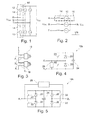
- Fig. 9 an embodiment of a part of a bridging unit 26 is shown.
- the outputs Y1 and Y2 in the Fig. 9 illustrated circuit 26 may include one or more bistable relays 34 and / or one or more gate controls 40 are driven for power electronic switches 36.
- the input U3 of the circuit 26 is connected to the input X1 of the converter cell 18, the input GND to the output X2 of the converter cell 18.
- the energy required for simultaneous switching (for example from one or more bistable relays 34 and / or one or more power electronic switches 36) is set in a capacitor C1 via the voltage or the capacitance.
- the energy store 48 comprises the capacitor C1.
- the circuit of Y1 via the capacitor C1 to the output Y2 to trigger the relay 34 and / or the gate control 40 is closed with a thyristor T1. This ensures that after an ignition pulse, the current from the capacitor C1 flows until the capacitor C1 is completely discharged or the circuit is interrupted.
- the energy for the energy storage C1 is either from the power supply belonging to the converter cell via the input U2 or via a series circuit of Transil or.
- the ignition of the thyristor T1 can be done either via too high a voltage at the input U3 or X1 of the circuit 26 or via a control input CTR.
- the charge and thus the voltage U1 on the capacitor C1 by integrated in the control unit 58, 60 power supply to the value held the voltage U2.
- the controller 58, 60 gives the command or the closing signal to bridge the converter cell 18
- the control terminal of the thyristor T1 is directly driven via the input CTR and thus the thyristor T1 is brought into the conducting state.
- the capacitor C1 is discharged via the connected bistable relays 34 and the gate controls 40, respectively.
- the voltage U1 is tapped across the capacitor C1 and via a series connection of Zener diodes 66 or Transil diodes 66 and a diac 68 to the control terminal of the thyristor T1 connected.
- Zener diodes 66 or Transil diodes 66 and a diac 68 to the control terminal of the thyristor T1 connected.
- Diac 68 changes its transmission characteristic so that the voltage drop across it decreases sharply. This increases the drive current for the thyristor T1 and adds triggering circuit 26 with hysteresis. This ensures that a single exceeding of the threshold voltage U1 reliably causes the triggering.
- the driver 42 includes elements 66, 68 and T1.
- the threshold voltage for charging the capacitor C1 can be adjusted.
- the threshold voltage of the block 66, 68 should be higher than the voltage U2, otherwise in normal operation, when the power supply unit of the connected converter cell 18 supplies the voltage U2, the ignition mechanism of the threshold circuit 26 is already set in motion.
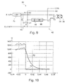
- the Fig. 10 shows a diagram of voltage waveforms, which in a measurement at the bypass circuit 26 from the Fig. 9 were won.
- the time t in seconds is plotted to the right and the voltage in volts to the top.
- the capacitor voltage 72 is divided by 10.
- Graph 72 shows the voltage across capacitor C1, during which voltage U3 74 has been increased continuously, to a threshold voltage at which transistor chain 70 becomes conductive and charges capacitor C1 as soon as the threshold voltage for the thyristor T1 fires has been reached, the voltage U3 short-circuits and thus bypasses the converter cell 18.
Landscapes
- Engineering & Computer Science (AREA)
- Power Engineering (AREA)
- Inverter Devices (AREA)
- Power Conversion In General (AREA)
- Dc-Dc Converters (AREA)
Description
Diese Erfindung betrifft das Gebiet der Leistungselektronik. Insbesondere betrifft diese Erfindung eine Überbrückungseinheit zum Kurzschließen einer Umrichterzelle, eine Umrichterzelle, einen Umrichter und ein Verfahren zum Kurzschließen einer Umrichterzelle.This invention relates to the field of power electronics. More particularly, this invention relates to a bypass unit for shorting a converter cell, a converter cell, an inverter, and a method of shorting a converter cell.
Bestimmte Typen von Umrichtern, beispielsweise modulare Multiniveauumrichter (modular multi-level converters - M2LC-Umrichter) können eine Mehrzahl von Umrichterzellen aufweisen, die die leistungselektronischen Schalter umfassen, mit denen der durch den Umrichter zu schaltende Strom geschaltet wird. Bei derartigen Zellen kann immer wieder das Problem auftreten, dass eine oder mehrere der Zellen eines Umrichters umgangen bzw. kurzgeschlossen werden müssen. Dies kann beispielsweise dann der Fall sein, wenn an einer Zelle oder mehreren Zellen ein Überstrom oder eine Überspannung entsteht, was durch einen externen Fehler (beispielsweise ein Erdfehler) oder durch einen internen Fehler der Umrichterzelle bedingt sein kein.Certain types of converters, such as modular multi-level converters (M2LC inverters), may include a plurality of converter cells that include the power electronic switches that switch the current to be switched by the inverter. In the case of such cells, the problem can repeatedly arise that one or more of the cells of an inverter must be bypassed or short-circuited. This may be the case, for example, if an overcurrent or an overvoltage occurs at one cell or several cells, which is due to an external fault (for example, a ground fault) or due to an internal fault of the converter cell.
Im Falle eines erheblichen internen Fehlers der Umrichterzelle kann es vorteilhaft sein, wenn die Überbrückung der Umrichterzelle dauerhaft ist. Dafür wurden bereits ein pyrotechnischer Schließer (
Im Falle von externen Fehlern kann es notwendig sein, dass durch die Überbrückungseinheit kurze Stromstöße aufgenommen und an der Umrichterzelle vorbeigeleitet werden müssen. Für diesen Zweck wurde vorgeschlagen, beispielsweise einen Thyristor parallel zur Freilaufdiode der Umrichterschalter anzuordnen (
Nicht rückstellbare Überbrückungseinheiten (wie beispielsweise ein pyrotechnischer Schließer oder durchlegierende Bauelemente) müssen in aufwändiger Art und Welse aus den Umrichterzellen ausgebaut und durch neue noch nicht benutzte Überbrückungseinheiten ausgetauscht werden. Dies kann sehr zeit- und kostenintensiv sein.Non-recoverable bridging units (such as a pyrotechnic NO or durchlegierende components) must be removed in a complex type and catfish from the converter cells and replaced by new unused bridging units. This can be very time consuming and costly.
Bei Thyristoren kann auch das Problem entstehen, dass die Überbrückungseinheit ohne externe Energie in den offenen Zustand zurückfällt. Ein kompletter Stromausfall des Umrichters würden in diesem Fall auch die Überbrückungseinheiten von defekten Zellen wieder in den nicht leitenden Zustand versetzen.In the case of thyristors, the problem may arise that the bridging unit falls back into the open state without external energy. A complete power failure of the inverter would in this case also put the bridging units of defective cells back into the non-conductive state.
In der
Es ist Aufgabe der Erfindung, einen Umrichter mit wartungsfreundlichen und zuverlässigen Umrichterzellen bereitzustellen.It is an object of the invention to provide a converter with maintenance-friendly and reliable converter cells.
Diese Aufgabe wird durch den Gegenstand der unabhängigen Ansprüche gelöst. Weitere Ausführungsformen der Erfindung ergeben sich aus den abhängigen Ansprüchen.This object is solved by the subject matter of the independent claims. Further embodiments of the invention will become apparent from the dependent claims.
Ein erster Aspekt der Erfindung betrifft eine Überbrückungseinheit zum Kurzschließen eines ersten und eines zweiten Eingangs einer Umrichterzelle eines modularen Umrichters.A first aspect of the invention relates to a bypass unit for shorting a first and a second input of a converter cell of a modular converter.
Der Umrichter kann ein Leistungsumrichter sein, der dazu ausgeführt ist, Ströme von mehreren zehn oder mehreren hundert Ampere und mehreren tausend Volt umzurichten. Unter Umrichten ist dabei der Vorgang zu verstehen, bei dem aus einer Gleichspannung eine Wechselspannung, aus einer Wechselspannung eine Gleichspannung oder aus einer Wechselspannung erster Frequenz eine Wechselspannung zweiter Frequenz erzeugt wird. Der Umrichter kann ein modularer Multiniveauumrichter (M2LC), ein indirekter bzw. direkter Umrichter sein. Diese beiden Arten von Umrichtern werden oft auch Chainlink-Umrichter genannt, da ihre Umrichterzellen kettenförmig angeordnet sind.The converter may be a power converter designed to convert currents of tens or hundreds of amperes and several thousand volts. In this case, conversion is understood to mean the process in which an AC voltage is generated from a DC voltage, a DC voltage from an AC voltage or an AC voltage of the second frequency from an AC voltage of the first frequency. The inverter can be a modular multi-level converter (M2LC), an indirect or be direct inverter. These two types of inverters are often called chain-link inverters because their converter cells are arranged in a chain.
Eine Umrichterzelle kann eine unipolare Zelle (eine Halbbrücke) sein, beispielsweise bei einem indirekten M2LC-Umrichter, kann aber auch eine bipolare Zelle (eine Vollbrücke) sein, beispielsweise bei einem direkten M2LC-Umrichter oder einem Chain link-Umrichter. Eine Umrichterzelle weist in der Regel mehrere elektronische Schalter wie Thyristoren oder IGBTs auf. Darüber hinaus umfasst eine Umrichterzelle einen Energiespeicher, beispielsweise einen Kondensator. Zum Aufbau eines Umrichters kann eine Mehrzahl von Umrichterzellen über ihre Eingänge in Reihe geschaltet werden.A converter cell may be a unipolar cell (a half-bridge), for example an indirect M2LC inverter, but may also be a bipolar cell (a full bridge), for example, a direct M2LC inverter or a chain link converter. A converter cell usually has a plurality of electronic switches such as thyristors or IGBTs. In addition, a converter cell comprises an energy store, for example a capacitor. To construct an inverter, a plurality of converter cells can be connected in series via their inputs.
Gemäß einer Ausführungsform der Erfindung umfasst die Überbrückungseinheit ein bistabiles mechanisches Relais, wobei das bistabile mechanische Relais dazu ausgeführt ist, den ersten Eingang mit dem zweiten Eingang elektrisch zu verbinden und/oder die Verbindung wieder zu unterbrechen. Ein bistabiles mechanisches Relais verliert seinen aktuellen Schaltzustand nicht, wenn sein Steuereingang abgetrennt ist.According to one embodiment of the invention, the bridging unit comprises a bistable mechanical relay, wherein the bistable mechanical relay is designed to electrically connect the first input to the second input and / or to interrupt the connection again. A bistable mechanical relay does not lose its current switching state when its control input is disconnected.
Weiterhin umfasst die Überbrückungseinheit einen leistungselektronischen Schalter. Der leistungselektronische Schalter kann dazu ausgeführt sein, den ersten Eingang mit dem zweiten Eingang der Umrichterzelle elektrisch zu verbinden bzw. die Verbindung wieder zu unterbrechen.Furthermore, the bridging unit comprises a power electronic switch. The power electronic switch can be designed to electrically connect the first input to the second input of the converter cell or to interrupt the connection again.
Ein leistungselektronischer Schalter kann gegenüber einem Relais um Größenordnungen schneller geschaltet werden. Beispielsweise kann die Überbrückungseinheit gleichzeitig ein Steuersignal an den leistungselektronischen Schalter und das bistabile mechanische Relais schicken, wonach zuerst nach einem sehr kurzen Zeitrahmen (Mikrosekunden) der leistungselektronische Schalter schließt und anschließend das bistabile mechanische Relais (Millisekunden) schließt.A power electronic switch can be switched orders of magnitude faster than a relay. For example, the bypass unit may simultaneously send a control signal to the power electronic switch and the bistable mechanical relay, after which after a very short time frame (microseconds), the power electronic switch closes and then closes the bistable mechanical relay (milliseconds).
Weiterhin umfasst die Überbrückungseinheit eine Ansteuerung zum Schalten des bistabilen mechanischen Relais und des leistungselektronischen Schalters.Furthermore, the bridging unit comprises a drive for switching the bistable mechanical relay and the power electronic switch.
Darüber hinaus umfasst die Überbrückungseinheit einen Energiespeicher zur Versorgung der Ansteuerung, des mechanischen Relais und des leistungselektronischen Schalters mit Energie. Ein derartiger Energiespeicher kann beispielsweise ein Kondensator sein, der beispielsweise über die an der Umrichterzelle anliegenden Spannung direkt oder indirekt geladen werden kann. Insbesondere kann es auch möglich sein, dass der Energiespeicher bzw. der Kondensator speziell durch Überspannung an der Umrichterzelle weiter geladen wird.In addition, the bridging unit comprises an energy store for supplying the drive, the mechanical relay and the power electronic switch with energy. Such an energy store can be for example a capacitor which can be charged directly or indirectly, for example, via the voltage applied to the converter cell. In particular, it may also be possible for the energy store or the capacitor to continue to be charged by overvoltage at the converter cell.
Weiterhin erfolgt die Ansteuerung der Überbrückungseinheit durch eine passive Überspannungserfassung zwischen X1 und X2. Unter einer passiven Überspannungserfassung kann dabei ein elektronisches Bauelement verstanden werden, das allein durch das Vorhandensein der Überspannung seinen internen Zustand ändert. Beispiele für solche Bauelemente sind Transil- bzw. Suppressor-Dioden.Furthermore, the control of the bridging unit is effected by a passive overvoltage detection between X1 and X2. Under a passive overvoltage detection can be understood an electronic component that changes its internal state only by the presence of the overvoltage. Examples of such devices are transil or suppressor diodes.
Beispielsweise könnte die passive Überspannungserfassung wenigstens eine Suppressor-Diode umfassen bzw. eine Suppressor-Kette aus in Reihe geschalteter Suppressor-Dioden umfassen. Suppressor-Dioden werden bei einer bestimmten Schwellenspannung leitend, mit einer Kette von Suppressor-Dioden kann damit eine Schwellenspannung eingestellt werden, mit der die Kette leitend wird.For example, the passive overvoltage detection could comprise at least one suppressor diode or comprise a suppressor chain of serially connected suppressor diodes. Suppressor diodes are turned on at a certain threshold voltage, with a chain of suppressor diodes can thus be set a threshold voltage with which the chain is conductive.
Es kann eine Kette von in Reihe geschalteter Suppressor-Dioden, die derart ausgewählt sind, dass sie bei einer vorbestimmten Schwellenspannung leitend werden, ein entsprechendes Signal erzeugen, um das bistabile mechanische Relais und/oder den leistungselektronische Schalter der Überbrückungseinheit zu schalten.A chain of serially connected suppressor diodes selected to become conductive at a predetermined threshold voltage may generate a corresponding signal to switch the bistable mechanical relay and / or the power electronic switch of the bypass unit.
Darüber hinaus wird beim Überschreiten der Überspannung der Energiespeicher durch die Überspannung geladen oder zusätzlich geladen.In addition, when the overvoltage is exceeded, the energy store is charged or additionally charged by the overvoltage.
Außerdem weist die Ansteuerung einen weiteren elektronischen Schalter auf, der geschlossen wird, wenn eine Spannung am Energiespeicher einen vordefinierten Wert überschreitet und die Ansteuerung das bistabilen Relais und/oder der leistungselektronischen Schalter aus dem Energiespeicher mit Strom versorgt.In addition, the control has a further electronic switch, which is closed when a voltage across the energy store exceeds a predefined value and the control supplies the bistable relay and / or the power electronic switch from the energy store with power.
Weiterhin weist die Ansteuerung eine Hysterese auf, so dass beim Unterschreiten der Spannung am Energiespeicher das Relais und/oder der leistungselektronische Schalter weiter mit Strom aus dem Energiespeicher versorgt werden. Beispielsweise kann das Relais dann mit Strom bzw. Spannung aus dem Energiespeicher versorgt werden, wenn die Spannung am Energiespeicher einen bestimmten Wert überschreitet, der sicherstellt, dass das Relais so lange mit Strom versorgt wird, bis es in den geöffneten bzw. den ungeöffneten Zustand überwechseln konnte. Das Relais wird dann so lange aus dem Energiespeicher mit Spannung versorgt, bis die Spannung am Energiespeicher einen gewissen Wert unterschreitet und den Energiespeicher wieder vom Relais trennt. Eine Hysterese und eine Schwellwertermittlung für die Spannung am Energiespeicher kann beispielsweise durch einen Diac, der mit einer Suppressor-Diode in Reihe geschaltet ist, erreicht werden.Furthermore, the control has a hysteresis, so that when falling below the voltage at the energy storage, the relay and / or the power electronic switch are further supplied with power from the energy storage. For example, the relay can then be supplied with current or voltage from the energy store when the voltage across the energy store exceeds a certain value, which ensures that the relay is supplied with power until it changes to the open or unopened state could. The relay is then supplied with voltage from the energy store until the voltage at the energy store falls below a certain value and the energy store is disconnected from the relay again. A hysteresis and a threshold value determination for the voltage at the energy store can be achieved, for example, by means of a diac, which is connected in series with a suppressor diode.
Gemäß einer Ausführungsform der Erfindung ist der leistungselektronische Schalter dazu ausgeführt, innerhalb von einigen bis einigen zehn Mikrosekunden zu schließen.According to one embodiment of the invention, the power electronic switch is designed to close within a few to a few tens of microseconds.
Gemäß einer Ausführungsform der Erfindung ist das bistabile mechanische Relais dazu ausgeführt, innerhalb von einigen bis einigen zehn Millisekunden zu schließen.According to one embodiment of the invention, the bistable mechanical relay is designed to close within a few to a few tens of milliseconds.
Auch wenn die Umrichterzelle beispielsweise auf Grund der geschlossenen Überbrückungseinheit nach einiger Zeit die interne Speisung verliert, behält das bistabile mechanische Relais seinen geschlossenen Zustand bei.Even if the converter cell loses the internal supply after some time because of the closed bridging unit, for example, the bistable mechanical relay maintains its closed state.
Die Überbrückungseinheit kann mit einfacher Technologie aufgebaut werden. Es sind keine pyrotechnischen Schließer oder Vakuumschaltröhren notwendig. Durch das bistabile mechanische Relais bleibt die Überbrückungseinheit nach Betätigung auch ohne externe Energie sicher in einem stabilen Zustand. Da das bistabile mechanische Relais und der leistungselektronische Schalter rückstellbar ausführbar sind, kann auch die Überbrückungseinheit rückstellbar aufgebaut werden. Darüber hinaus kann die Überbrückungseinheit mit der Umrichterzelle parallel zu deren Eingängen geschaltet werden, im Gegensatz zu durchlegierenden Halbleiterbauelementen. Zusätzlich kann die Überbrückungseinheit eine bipolare Überspannungsbegrenzung für eine hochohmige Umrichterzelle ermöglichen.The bridging unit can be constructed with simple technology. There are no pyrotechnic NO or vacuum interrupters necessary. Thanks to the bistable mechanical relay, the bypass unit remains safely in a stable state after operation even without external energy. Since the bistable mechanical relay and the electronic power switch are reset executable, the bridging unit can be constructed recoverable. In addition, the bypass unit can be connected to the converter cell in parallel with their inputs, in contrast to semiconductor components which break through. In addition, the bridging unit can enable a bipolar overvoltage limitation for a high-impedance converter cell.
Durch die Überbrückungseinheit können zudem eine Vielzahl von Fehlerfällen auf Umrichterebene abgedeckt werden, insbesondere auch Erdfehler und Kurzschlüsse. Die Überbrückungseinheit kann zudem einen redundanten Pfad, zum Beispiel für einen DC-Link-Kurzschlusspfad bieten.The bridging unit can also cover a large number of fault cases at the converter level, in particular also earth faults and short circuits. The bridging unit may also provide a redundant path, for example for a DC link shorting path.
Gemäß einer Ausführungsform der Erfindung umfasst der leistungselektronische Schalter zwei antiparallele Thyristoren. Allgemeiner ist es auch möglich, dass die Überbrückungseinheit wenigstens einen Thyristor umfasst.According to one embodiment of the invention, the power electronic switch comprises two antiparallel thyristors. More generally, it is also possible that the bridging unit comprises at least one thyristor.
Gemäß einer Ausführungsform der Erfindung umfasst der leistungselektronische Schalter einen Triac.According to one embodiment of the invention, the power electronic switch comprises a triac.
Gemäß einer Ausführungsform ist die Ansteuerung dazu ausgeführt, ein Schließ- oder Rücksetzsignal für das Relais und/oder den leistungselektronischen Schalter zu empfangen und, in Reaktion auf das Schließsignal oder das Rücksetzsignal das Relais und/oder den leistungselektronischen Schalter zu schließen oder zu öffnen (d. h. zurückzusetzen).According to one embodiment, the drive is adapted to receive a reset or reset signal for the relay and / or the power electronic switch and to close or open the relay and / or the power electronic switch in response to the closing signal or the reset signal (ie reset).
Gemäß einer Ausführungsform der Erfindung ist die Ansteuerung dazu ausgeführt, eine Überspannung und/oder einen Überstrom zwischen dem ersten Eingang und dem zweiten Eingang der Umrichterzelle zu ermitteln. Dies kann beispielsweise dadurch geschehen, dass die Ansteuerung Messsignale einer Spannungsmesseinheit und einer Strommesseinheit an den ersten und/oder zweiten Ausgang der Umrichterzelle empfängt und diese weiterverarbeitet.According to one embodiment of the invention, the drive is designed to determine an overvoltage and / or an overcurrent between the first input and the second input of the converter cell. This can be done, for example, by the control receiving measuring signals of a voltage measuring unit and of a current measuring unit at the first and / or second output of the converter cell and processing them further.
Gemäß einer Ausführungsform der Erfindung ist die Ansteuerung dazu ausgeführt, das Relais und/oder den leistungselektronischen Schalter zu schließen, wenn die Überspannung und/oder der Überstrom ermittelt werden. Beispielsweise kann die Ansteuerung die beiden Schaltelemente dann schließen, wenn die Spannung zwischen dem ersten und dem zweiten Eingang einen vorbestimmten Schwellwert überschreitet. Genauso kann die Ansteuerung die beiden Schaltelemente schließen, wenn ein Strom im ersten und/oder zweiten Eingang einen vorbestimmten Schwellwert überschreitet.According to one embodiment of the invention, the drive is designed to close the relay and / or the electronic power switch when the overvoltage and / or the overcurrent are detected. For example, the drive can close the two switching elements when the voltage between the first and the second input exceeds a predetermined threshold. Similarly, the drive can close the two switching elements when a current in the first and / or second input exceeds a predetermined threshold.
Gemäß einer Ausführungsform der Erfindung ist die Ansteuerung der Überbrückungseinheit dazu ausgeführt, (beispielsweise neben dem Überspannungschließsignal) ein externes Schließsignal und/oder Rückstellsignal zu empfangen oder zu erfassen. Dieses externe Schließsignal kann von der Diagnoseeinheit der Umrichterzelle oder von einer Systemschutzeinheit des Umrichters stammen. Gemäß einer Ausführungsform der Erfindung ist die Ansteuerung dazu ausgeführt, das Relais und/oder den leistungselektronischen Schalter zu schließen, wenn ein externes Schließsignal erfasst wurde.According to one embodiment of the invention, the activation of the bridging unit is designed to receive or detect an external closing signal and / or reset signal (for example, in addition to the overvoltage closing signal). This external closing signal can come from the diagnostic unit of the converter cell or from a system protection unit of the converter. According to one embodiment of the invention, the drive is designed to close the relay and / or the electronic power switch when an external closing signal has been detected.
Gemäß einer Ausführungsform der Erfindung ist die Ansteuerung dazu ausgeführt, das Relais und/oder den leistungselektronischen Schalter zu öffnen, wenn ein externes Rückstellsignal erfasst wurde.According to one embodiment of the invention, the drive is designed to open the relay and / or the electronic power switch when an external reset signal has been detected.
Ein weiterer Aspekt der Erfindung betrifft eine Umrichterzelle.Another aspect of the invention relates to a converter cell.
Gemäß einer Ausführungsform der Erfindung umfasst die Umrichterzelle eine Überbrückungseinheit, so wie sie vorstehend und im Folgenden beschrieben wird.According to one embodiment of the invention, the converter cell comprises a bridging unit as described above and below.
Gemäß einer Ausführungsform der Erfindung umfasst die Umrichterzelle eine Diagnoseeinheit, die dazu ausgeführt ist, ein Schließsignal und/oder ein Rücksetzsignal für die Überbrückungseinheit zu übermitteln. Die Diagnoseeinheit kann zudem wichtige Mess- und Zustandsgrößen an die zentrale Umrichter- und Systemsteuerung liefern.According to one embodiment of the invention, the converter cell comprises a diagnostic unit which is designed to transmit a closing signal and / or a reset signal for the bridging unit. The diagnostic unit can also provide important measurement and state variables to the central inverter and system controller.
Gemäß einer Ausführungsform der Erfindung umfasst die Umrichterzelle eine Überstromabschaltung, die eine von der Überbrückungseinheit unabhängig agierende Überstromabschaltung sein kann. Beispielsweise kann die Überstromabschaltung im Falle einer Überspannung und/oder eines Überstroms die Halbleiter der Umrichterzelle abschalten.According to one embodiment of the invention, the converter cell comprises an overcurrent cut-off, which may be an overcurrent cut-off that acts independently of the bypass unit. For example, in the event of an overvoltage and / or an overcurrent, the overcurrent shutdown can switch off the semiconductors of the converter cell.
Gemäß einer Ausführungsform der Erfindung kann die Umrichterzelle bei einem aufgeprägten Überstrom (bzw. einem Stoßstrom) innerhalb von Mikrosekunden den Fehlerstrom in den aktiven Schaltern der Umrichterzelle (IGBTs, IGCTs) selbstständig unterbrechen.According to one embodiment of the invention, the converter cell can automatically interrupt the fault current in the active switches of the converter cell (IGBTs, IGCTs) in the event of an impressed overcurrent (or a surge current) within microseconds.
Gemäß einer Ausführungsform der Erfindung umfasst die Umrichterzelle eine Entsättigungsüberwachung eines IGBTs der Umrichterzelle. Das Erkennen derartiger Fehler oder Probleme kann auf einer Entsättigungsüberwachung von IGBTs oder Transistoren basieren. Es kann aber auch auf einer sehr schnellen Überstromerfassung im Falle von IGCTs oder anderen abschaltbaren Elementen basieren.According to one embodiment of the invention, the converter cell comprises a desaturation monitoring of an IGBT of the converter cell. Detecting such faults or problems may be based on desaturation monitoring of IGBTs or transistors. It can also be based on a very fast overcurrent detection in the case of IGCTs or other disconnectable elements.
Ein weiterer Aspekt der Erfindung betrifft einen Umrichter.Another aspect of the invention relates to an inverter.
Gemäß einer Ausführungsform der Erfindung umfasst der Umrichter eine Mehrzahl von Umrichterzellen, so wie sie vorstehend und im Folgenden beschrieben sind.According to one embodiment of the invention, the converter comprises a plurality of converter cells, as described above and below.
Gemäß einer Ausführungsform der Erfindung umfasst der Umrichter eine Systemschutzeinheit. Die Systemschutzeinheit kann dazu ausgeführt sein, bei einem Umrichter- und/oder Systemfehler alle, oder eine Auswahl, der leistungselektronischen Schalter und/oder der Relais der Überbrückungseinheiten der Umrichterzellen zu schließen und wahlweise nach der Fehlerklärung wieder zurückzustellen (d. h. zu öffnen). die dazu ausgeführt ist, jeder Umrichterzelle aus der Mehrzahl von Umrichterzellen ein Überbrückungssignal und/oder ein Rücksetzsignal zu übermitteln. In gewissen Fehlerfällen genügt die rasche und eigenständige Abschaltung auf dem Niveau der Umrichterzelle nicht und die Systemschutzeinheit sendet ein koordiniertes Überbrückungssignal an alle oder ausgewählte Zellen.According to one embodiment of the invention, the converter comprises a system protection unit. The system protection unit may be designed to close all or a selection of the power electronic switches and / or the relays of the bridging units of the converter cells in an inverter and / or system error and optionally after the faulty reset (ie open). which is designed to transmit a bridging signal and / or a reset signal to each converter cell of the plurality of converter cells. In certain cases of error, the rapid and autonomous shutdown at the level of the inverter cell is not sufficient and the system protection unit sends a coordinated bypass signal to all or selected cells.
Im Folgenden werden Ausführungsbeispiele der Erfindung mit Bezug auf die beiliegenden Figuren detailliert beschrieben.Embodiments of the invention will now be described in detail with reference to the accompanying drawings.
-
Fig. 1 zeigt einen Umrichter gemäß einem Ausführungsbeispiel der Erfindung.Fig. 1 shows a converter according to an embodiment of the invention. -
Fig. 2 zeigt einen weiteren Umrichter gemäß einem Ausführungsbeispiel der Erfindung.Fig. 2 shows a further converter according to an embodiment of the invention. -
Fig. 3 zeigt eine Kette von Umrichterzellen gemäß einer Ausführungsform der Erfindung.Fig. 3 shows a chain of converter cells according to an embodiment of the invention. -
Fig. 4 zeigt eine unipolare Umrichterzelle gemäß einem Ausführungsbeispiel der Erfindung.Fig. 4 shows a unipolar inverter cell according to an embodiment of the invention. -
Fig. 5 zeigt eine bipolare Umrichterzelle gemäß einem Ausführungsbeispiel der Erfindung.Fig. 5 shows a bipolar converter cell according to an embodiment of the invention. -
Fig. 6 zeigt eine Umrichterzelle gemäß einem Ausführungsbeispiel der Erfindung.Fig. 6 shows a converter cell according to an embodiment of the invention. -
Fig. 7 zeigt eine Umrichterzelle gemäß einem Ausführungsbeispiel der Erfindung.Fig. 7 shows a converter cell according to an embodiment of the invention. -
Fig. 8 zeigt ein Flussdiagramm für ein Verfahren zum Kurzschließen einer Umrichterzelle.Fig. 8 shows a flowchart for a method for shorting a drive cell. -
Fig. 9 zeigt ein Ausführungsbeispiel einer Überbrückungseinheit gemäß einem Ausführungsbeispiel der Erfindung.Fig. 9 shows an embodiment of a bridging unit according to an embodiment of the invention. -
Fig. 10 zeigt ein Diagramm mit Spannungsverläufen für die Überbrückungseinheit aus derFig. 9 gemäß einem Ausführungsbeispiel der Erfindung.Fig. 10 shows a diagram with voltage curves for the bridging unit from theFig. 9 according to an embodiment of the invention.
Die in den Figuren verwendeten Bezugszeichen und ihre Bedeutung sind in zusammenfassender Form in der Liste der Bezugszeichen aufgeführt. Grundsätzlich sind identische oder ähnliche Teile mit den gleichen Bezugszeichen versehen.The reference numerals used in the figures and their meaning are listed in summary form in the list of reference numerals. Basically, identical or similar parts are provided with the same reference numerals.
Der in der
Die
In der
Die
Grundsätzlich ist die Überbrückungseinheit 26 ein Bauelement, das in einem ersten leitenden Zustand einen sehr niedrigen Widerstand hat, so dass ein Strom zwischen den Eingängen X1 und X2 durch die Überbrückungseinheit 26 und nicht durch die anderen baulichen Komponenten der Umrichterzelle 18a fließt. In einem zweiten nicht leitenden Zustand, in dem die Überbrückungseinheit 26 einen sehr hohen Widerstand aufweist, kann kein oder zumindest nur ein sehr geringer Strom durch das Überbrückungselement 26 fließen. In diesem Fall verhält sich die Umrichterzelle 18a so, als ob das die Überbrückungseinheit 26 nicht vorhanden wäre.Basically, the
Alternativ können bei einer bipolaren Umrichterzelle zwei Überbrückungseinheiten eingesetzt werden, die jeweils einen äußeren Anschluss (X1, X2) mit dem gleichen Anschluss des Kondensators verbinden. Dann entspricht die bipolare Zelle genau zwei unipolaren Zellen, die an den beiden Anschlüssen des Kondensators verbunden wurden.Alternatively, in a bipolar converter cell, two bridging units may be used, each connecting an external terminal (X1, X2) to the same terminal of the capacitor. Then the bipolar cell corresponds exactly to two unipolar cells connected at the two terminals of the capacitor.
In der
Das Stoßstromelement 28 stellt die Stoßstromfestigkeit der Umrichterzelle 18 bereit. Beispielsweise müssen im Falle verschiedener Umrichterfehler oder externer Systemfehler extern aufgeprägte Stoßströme über die Eingänge X1 und X2 durch die Umrichterzelle mit Hilfe des Stoßstromelements 28 kurzzeitig aufgenommen werden. Darüber hinaus können auch mit demselben Schutzelement zellinterne Stoßströme zum Schutz der Redundanzelemente aufgenommen werden. Dies ist beispielsweise möglich, um den Zwischenkreis mit dem Kondensator 24 zu entladen, wenn beispielsweise bei der unipolaren Umrichterzelle 18a aus der
Das Redundanzelement 30 stellt die Redundanzfähigkeit der Umrichterzelle 18 bereit. Dabei kann unter Redundanzfähigkeit einer Umrichterzelle ein dauerhafter Kurzschluss der Zelle als Folge einer Zellenfehlfunktion verstanden werden.The
In der
Die Überbrückungseinheit 26 umfasst ein kombiniert mechanisch-elektrisches Überbrückungselement 32 aus einem bistabilen mechanischen Relais 34 und einem leistungselektronischen Schalter 36, der zwei antiparallele Thyristoren 38 oder einen Triac umfasst. Der leistungselektronische Schalter 36 umfasst eine Gate-Steuerung 40 bzw. Gate-Drive 40, der die elektronischen Schaltelemente 38, beispielsweise Thyristoren 38, über deren Gates schalten kann. Das kombiniert mechanisch-elektrische Überbrückungselement 32 wird von einer Ansteuerung 42 angesteuert, die ein Öffnen- bzw. Schließsignal über eine erste Signalleitung 44 an das mechanische Relais 34 und ein Öffnen- bzw. Schließsignal über eine zweite Signalleitung 46 an die Gate-Steuerung 40 und somit an den leistungselektronischen Schalter 36 senden kann.The bridging
Die Ansteuerung 42 sowie die Komponenten des Überbrückungselements 32, das heißt das Relais 34, die Gate-Steuerung 40 und die beiden Thyristoren 38 werden von einem Energiespeicher 48 mit Energie versorgt. Der Energiespeicher 48 ist dazu ausgeführt, genügend Energie bereitzustellen, um das mechanische und leistungselektronische Überbrückungselement 32, sowie deren zugehörige Schutzintelligenz in der Form der Ansteuerung 42 im Fehlerfall mit Energie zu versorgen. Der Energiespeicher 48 ist parallel zu dem Relais 34 und den beiden Thyristoren 36 an die Eingänge X1 und X2 der Umrichterzelle 18 angeschlossen und kann aus dem an der Umrichterzelle 18 über diese beiden Eingänge X1, X2 anliegenden Spannung Energie beziehen. Es ist aber auch möglich, dass der Energiespeicher 48 Energie aus einer Stromversorgung der Umrichterzelle 18 bezieht.The
Das an die Ausgänge X1 und X2 angeschlossene beispielsweise handelsübliche mechanische Relais 34 kann bezüglich der beim Einschalten angelegten Steuerspannung außerhalb der Spezifikation betrieben werden. Damit kann erreicht werden, dass die Schaltzeit des Relais 34 verkürzt wird. Darüber hinaus kann das Relais 34 bezüglich der Schaltspannung an den Kontakten außerhalb der Spezifikation betrieben werden, solange die funktional notwendigen Isolationsabstände eingehalten werden können. Das Relais 34 kann ein handelsübliches bistabiles Relais sein.For example, the commercially available
Die Ansteuerung 42 ist dazu ausgeführt, externe Schutzbefehle umzusetzen, die beispielsweise von einer Systemschutzeinheit 60 stammen, lokale Fehler auszuwerten, wie beispielsweise eine Überspannung, ein Überstrom oder eine Fehlermeldung der Umrichterzellendiagnose 58. Dazu kann Spannungsmessgerät 50 zwischen die beiden Eingänge X1, X2 geschaltet und/oder ein Strommessgerät 52 in den Eingang X1 bzw. den Eingang X2 geschaltet sein. Über eine Signalleitung 54 kann die Ansteuerung 42 die aktuelle Spannung UAC zwischen den Eingängen X1 und X2 dem Spannungsmessgerät 50 und über die Signalleitung 56 den aktuellen Strom IAC von dem Strommessgerät 52 empfangen.The
Die Ansteuerung 42 kann darüber hinaus von einer Steuerungs- und Diagnostikeinheit 58 der Umrichtezelle 18 Öffnen- und Schließsignale über eine Signalleitung 62 empfangen. Zum Ermitteln von Fehlern an der Umrichterzelle 18 kann die Einheit 58 beispielsweise die Werte der Spannung UAC, des Stroms IAC, der Spannung UDC und der Entsättigungsüberwachung (im Falle von IGBTs) oder Durchzünderfassung der Zelle (im Falle von IGCTs) empfangen. Die Ansteuerung 42 kann optional auch über die Signalleitung 62 ein Abschaltsignal an die Steuerung 58 der Umrichterzelle 18 senden.In addition, the
Darüber hinaus ist es möglich, dass die Ansteuerung 42 Öffnen- bzw. Schließsignale von einer Systemschutzeinheit 60 empfängt, die den gesamten Umrichter 10, 16 überwacht, in den die Umrichterzelle 18 eingebaut ist.Moreover, it is possible that the
Die
In einem Schritt S10 wird die Spannung UAC und/oder der Strom IAC zwischen den beiden Eingängen X1, X2 der Umrichterzelle 18 ermittelt.In a step S10, the voltage U AC and / or the current I AC between the two inputs X1, X2 of the
In einem Schritt S12 bestimmt die Ansteuerung 42, ob ein Schwellwert für die Spannung UAC und/oder den Strom IAC überschritten ist. Ist dies der Fall, entscheidet die Ansteuerung 42, das mechanisch-elektronische Überbrückungselement 32 zu schließen. In einem Schritt S14 ermittelt die Diagnoseeinheit 58 einen internen Fehler der Umrichterzelle 18. In einem Schritt S16 sendet die Diagnoseeinheit 58 ein Schließsignal an die Ansteuerung 42.In a step S12, the
In einem Schritt S18 stellt die Systemschutzeinheit 60 einen externen oder internen Fehler im Umrichter 10, 16 fest. Daraufhin sendet die Systemschutzeinheit 60 ein Schließsignal über die Signalleitung 62 an die Ansteuerung 42.In a step S18, the
Die Schritte S10 und S 12, S14 und S16 sowie S18 und S20 können alternativ zueinander oder auch gleichzeitig erfolgen.The steps S10 and S12, S14 and S16 as well as S18 and S20 may be performed alternatively to each other or simultaneously.
In einem Schritt S22 sendet die Ansteuerung 42 unter Berücksichtigung aller Informationen gegebenenfalls ein Schließsignal über die Signalleitung 44 an das Relais 34, das sich innerhalb von Millisekunden schließt und ein Schließsignal über die Signalleitung 46 an die Gate-Steuerung 40, das daraufhin die beiden Thyristoren 38 in ihren leitfähigen Zustand überführt. Die Thyristoren werden innerhalb von Mikrosekunden leitend.In a step S22, the
Erkennt die Diagnoseeinheit 58 oder die Systemschutzeinheit 60, dass der interne Fehler behoben ist bzw. dass der interne bzw. externe Fehler des Umrichters 10, 16 nicht mehr vorhanden ist, senden sie ein Öffnen-Signal an die Ansteuerung 42, die dann in einem Schritt S24 ein Öffnen-Signal an das Relais und/oder die Gate-Steuerung 40 sendet, woraufhin die ausgewählten Schaltelemente 34 und/oder 36 wieder geöffnet werden und die Überbrückung des Überbrückungselements 26 gegebenfalls wieder aufgehoben wird.If the
Ein externer Fehler, der durch die Systemschutzeinheit 60 festgestellt werden kann, kann beispielsweise ein Erdfehler sein. Bei einem Erdfehler, oder im Allgemeinen bei einem Fehler, der von der Systemschutzeinheit 60 festgestellt wird, wird ein Schließsignal an alle Überbrückungseinheiten 26 aller Umrichterzellen 18 des Umrichters 18 gesendet. In diesen Fällen ist es angezeigt nur den leistungselektronischen Schalter zu schließen. Dies führt dazu, dass alle Umrichterzellen 18 des Umrichters durch die Überbrückungseinheit 26 überbrückt werden. Darüber hinaus werden in diesem Fall auch die Hauptunterbrecher des Umrichters 10, 16 durch die Systemschutzeinheit 60 aktiviert.An external fault that may be detected by the
In der
Die zum gleichzeitigen Schalten notwendige Energie (beispielsweise von einem oder mehreren bistabilen Relais 34 und/oder eine oder mehrere leistungselektronische Schalter 36) wird in einem Kondensator C1 über die Spannung oder die Kapazität eingestellt. Der Energiespeicher 48 umfasst den Kondensator C1.The energy required for simultaneous switching (for example from one or more
Der Stromkreis von Y1 über den Kondensator C1 zum Ausgang Y2 zum Auslösen des Relais 34 und/oder der Gate-Steuerung 40 wird mit einem Thyristor T1 geschlossen. Dadurch wird erreicht, dass nach einem Zündimpuls der Strom aus dem Kondensator C1 so lange fließt, bis der Kondensator C1 vollständig entladen ist oder der Stromkreis unterbrochen wird.The circuit of Y1 via the capacitor C1 to the output Y2 to trigger the
Die Energie für den Energiespeicher C1 wird entweder aus der zur Umrichterzelle gehörigen Spannungsversorgung über den Eingang U2 oder über eine Reihenschaltung von Transil-bzw. Suppressor-Dioden 70 (und anschließender Gleichrichtung) der an den Eingängen X1, X2 der Umrichterzelle anliegenden Spannung (das heißt parallel zu den Relaiskontakten des Relais 34 oder parallel zu den Thyristoren 38) entnommen.The energy for the energy storage C1 is either from the power supply belonging to the converter cell via the input U2 or via a series circuit of Transil or. Suppressor diodes 70 (and subsequent rectification) of the voltage applied to the inputs X1, X2 of the converter cell voltage (that is parallel to the relay contacts of the
Das Zünden des Thyristors T1 kann entweder über eine zu hohe Spannung am Eingang U3 bzw. X1 der Schaltung 26 oder über einen Steuerungseingang CTR erfolgen.The ignition of the thyristor T1 can be done either via too high a voltage at the input U3 or X1 of the
Zum Zünden des Thyristors T1 über den Steuereingang CTR, an den beispielsweise die Diagnoseeinheit 58 und/oder die Systemschutzeinheit 60 angeschlossen sein kann, wird die Ladung und somit die Spannung U1 am Kondensator C1 durch in in der Steuereinheit 58, 60 integrierte Netzteil auf dem Wert der Spannung U2 gehalten. Sobald die Steuerung 58, 60 den Befehl bzw. das Schließsignal gibt, die Umrichterzelle 18 zu überbrücken, wird der Steueranschluss des Thyristors T1 über den Eingang CTR direkt angesteuert und somit der Thyristor T1 in den leitenden Zustand gebracht. Als Folge wird der Kondensator C1 über die angeschlossenen bistabilen Relais 34 bzw. die Gate-Steuerungen 40 entladen.To ignite the thyristor T1 via the control input CTR, to which, for example, the
Zum Zünden des Thyristors T1 über eine zu hohe Spannung U3 wird die Spannung U1 über dem Kondensator C1 abgegriffen und über eine Serienschaltung von Zener-Dioden 66 oder Transil-Dioden 66 und einem Diac 68 mit dem Steueranschluss des Thyristors T1 verbunden. Mit der Serienschaltung 66, 68 wird erreicht, dass ab einer bestimmten Schwellenspannung U1 ein Strom in den Steueranschluss des Thyristors T1 fließt und diesen zündet. Gleichzeitig verändert der Diac 68 seine Durchlasskennlinie derart, dass der Spannungsabfall darüber stark abnimmt. Dies erhöht den Ansteuerstrom für den Thyristor T1 und fügt der Auslöseschaltung 26 eine Hysterese hinzu. So wird erreicht, dass ein einmaliges Überschreiten der Schwellenspannung U1 zuverlässig die Auslösung bewirkt.To ignite the thyristor T1 via an excessively high voltage U3, the voltage U1 is tapped across the capacitor C1 and via a series connection of
Die Ansteuerung 42 umfasst die Elemente 66, 68 und T1 umfassen.The
Mit der Transil-Kette 70, die eine oder mehrere in Reihe geschaltete Transil-Dioden umfasst, kann die Schwellenspannung für das Aufladen des Kondensators C1 eingestellt werden. Die Schwellenspannung des Blocks 66, 68 sollte höher liegen als die Spannung U2, sonst würde im normalen Betriebsfall, wenn das Netzteil der angeschlossenen Umrichterzelle 18 die Spannung U2 liefert, der Zündmechanismus der Schwellenschaltung 26 bereits in Gang gesetzt.With the
Die
Der Graph 72 zeigt den Spannungsverlauf über den Kondensator C1, während dem die Spannung U3 74 kontinuierlich erhöht wurde, bis zu einer Schwellenspannung, bei der die Transil-Kette 70 leitend wird und den Kondensator C1 auflädt, sobald die Schwellenspannung für die Zündung des Thyristors T1 erreicht wurde, die Spannung U3 kurzschließt und somit die Umrichterzelle 18 überbrückt.Graph 72 shows the voltage across capacitor C1, during which
Bezugszeichen in den Ansprüchen sind nicht als Einschränkung anzusehen. Reference signs in the claims are not to be considered as limiting.
- 1010
- indirekter Umrichterindirect inverter
- 1212
- UmrichterzweigUmrichterzweig
- 1414
- Drosselthrottle
- 1616
- direkte Umrichterdirect converters
- 1818
- UmrichterzelleUmrichterzelle
- 18a18a
- unipolare UmrichterzelleUnipolar converter cell
- 18b18b
- bipolare Umrichterzellebipolar converter cell
- 2020
- FreilaufdiodeFreewheeling diode
- 2222
- leistungselektronischer Schalterpower electronic switch
- 2424
- Energiespeicherenergy storage
- 2626
- Überbrückungseinheitbridging unit
- 2828
- StoßstromelementSurge current element
- 3030
- Redundanzelementredundancy element
- 3232
- Überbrückungselementbridging element
- 3434
- Relaisrelay
- 3636
- elektronischer Schalterelectronic switch
- 3838
- Thyristorthyristor
- 4040
- Gate-SteuerungGate control
- 4242
- Ansteuerungcontrol
- 4444
- Signalleitungsignal line
- 4646
- Signalleitungsignal line
- 4848
- Energiespeicherenergy storage
- 5050
- Spannungsmesservoltmeter
- 5252
- Strommesserammeter
- 5454
- Signalleitungsignal line
- 5656
- Signalleitungsignal line
- 5858
- Steuerung/DiagnoseeinheitControl / diagnostic unit
- 6060
- SystemschutzeinheitSystem protection unit
- 6262
- Signalleitungsignal line
- 6464
- Signalleitungsignal line
- 6666
- Transildiodetransildiode
- 6868
- Diacdiac
- 7070
- Transil-KetteTransil chain
- 7272
- Kondensatorspannungcapacitor voltage
- 7474
- Spannung zwischen X1 und X2Voltage between X1 and X2
Claims (11)
- Bridging unit (26) for shorting a first input (X1) and a second input (X2) of a converter cell (18) of a modular converter (10), comprising:a bistable mechanical relay (34);a power-electronic switch (36);a drive (42) for switching the relay (34) and the power-electronic switch (36);wherein the bistable mechanical relay (34) is designed to electrically connect the first input (X1) to the second input (X2);wherein the power-electronic switch (36) is designed to electrically connect the first input (X1) to the second input (X2);wherein an energy store (48) is provided in order to supply power to the mechanical relay (34), the power-electronic switch (36) and the drive (42);wherein the drive (42) comprises passive overvoltage detection (70) and, if the overvoltage is exceeded,the energy store (48) is charged by the overvoltage;wherein the drive (42) has a further electronic switch (T1), which is closed when a voltage on the energy store (48) exceeds a predefined value, andthe drive supplies current from the energy store to the bistable relay (34) and/or to the power-electronic switch (36), andwherein the drive (42) has hysteresis, such that, if the voltage on the energy store (48) is undershot,the relay (34) and/or the power-electronic switch (36) are/is still supplied with current from the energy store.
- Bridging unit (26) according to Claim 1,
wherein the power-electronic switch (36) is designed to close within a few to a few tens of microseconds, and/or
wherein the bistable mechanical relay (34) is designed to close within a few to a few tens of milliseconds. - Bridging unit (26) according to Claim 1 or 2,
wherein the power-electronic switch (36) comprises two back-to-back parallel thyristors (38), and/or wherein the power-electronic switch (36) comprises a triac. - Bridging unit (26) according to one of the preceding claims,
wherein the drive (42) is designed to receive a closing signal;
wherein the drive (42) is designed to close the relay (34) and/or the power-electronic switch (36) in reaction to the closing signal. - Bridging unit (26) according to one of the preceding claims,
wherein the drive (42) is designed to receive a reset signal;
wherein the drive (42) is designed to open the relay (34) and/or the power-electronic switch (36) in reaction to the reset signal. - Bridging unit (26) according to one of the preceding claims,
wherein the drive (42) is designed to determine an overvoltage and/or an overcurrent between the first input (X1) and the second input (X2);
wherein the drive (42) is designed to close the relay (34) and/or the power-electronic switch (36) when the overvoltage and/or the overcurrent are/is determined. - Bridging unit (26) according to one of the preceding claims,
wherein the drive (42) is designed to detect an external closing signal and/or reset signal;
wherein the drive (42) is designed to close the relay (34) and/or the power-electronic switch (36) when an external closing signal has been detected; wherein the drive (42) is designed to open the relay (34) and/or the power-electronic switch (36) when an external reset signal has been detected. - Converter cell (18), comprising:a bridging unit (26) according to one of Claims 1 to 7.
- Converter cell (18) according to Claim 8, furthermore comprising:overcurrent disconnection (58) and/ordesaturation monitoring of an IGBT in the converter cell (18);wherein the overcurrent disconnection (58) is designed to disconnect semiconductor elements in the converter cell (18) in the event of an overcurrent.
- Converter (10) comprising:a plurality of converter cells (18) according to Claim 8 or 9.
- Converter (10) according to Claim 10, furthermore comprising:a system protection unit;wherein the system protection unit is designed to close power-electronic switches in the bridging units (26) of the converter cells (18) in the event of a converter and/or system fault, and to selectively reset them again after the fault has been rectified.
Priority Applications (8)
| Application Number | Priority Date | Filing Date | Title |
|---|---|---|---|
| EP10157722A EP2369725B1 (en) | 2010-03-25 | 2010-03-25 | Short circuiting unit |
| CA2734911A CA2734911C (en) | 2010-03-25 | 2011-03-23 | Bridging unit |
| US13/071,184 US8456786B2 (en) | 2010-03-25 | 2011-03-24 | Bridging unit |
| RU2011111203/28A RU2461912C1 (en) | 2010-03-25 | 2011-03-24 | Bypass module |
| KR1020110026569A KR101197066B1 (en) | 2010-03-25 | 2011-03-24 | Bridging unit |
| BRPI1100945-4A BRPI1100945A2 (en) | 2010-03-25 | 2011-03-25 | converter cell and connecting unit |
| JP2011067555A JP5431398B2 (en) | 2010-03-25 | 2011-03-25 | Bridging unit |
| CN201110084784.7A CN102201728B (en) | 2010-03-25 | 2011-03-25 | Bridging Unit |
Applications Claiming Priority (1)
| Application Number | Priority Date | Filing Date | Title |
|---|---|---|---|
| EP10157722A EP2369725B1 (en) | 2010-03-25 | 2010-03-25 | Short circuiting unit |
Publications (2)
| Publication Number | Publication Date |
|---|---|
| EP2369725A1 EP2369725A1 (en) | 2011-09-28 |
| EP2369725B1 true EP2369725B1 (en) | 2012-09-26 |
Family
ID=42646807
Family Applications (1)
| Application Number | Title | Priority Date | Filing Date |
|---|---|---|---|
| EP10157722A Active EP2369725B1 (en) | 2010-03-25 | 2010-03-25 | Short circuiting unit |
Country Status (8)
| Country | Link |
|---|---|
| US (1) | US8456786B2 (en) |
| EP (1) | EP2369725B1 (en) |
| JP (1) | JP5431398B2 (en) |
| KR (1) | KR101197066B1 (en) |
| CN (1) | CN102201728B (en) |
| BR (1) | BRPI1100945A2 (en) |
| CA (1) | CA2734911C (en) |
| RU (1) | RU2461912C1 (en) |
Families Citing this family (46)
| Publication number | Priority date | Publication date | Assignee | Title |
|---|---|---|---|---|
| US8731765B2 (en) * | 2011-06-28 | 2014-05-20 | GM Global Technology Operations LLC | Method and apparatus for fault detection in a torque machine of a powertrain system |
| WO2013064310A1 (en) | 2011-11-03 | 2013-05-10 | Abb Technology Ag | Inverter circuit and method for operating such an inverter circuit |
| CN105610312A (en) * | 2011-11-11 | 2016-05-25 | 台达电子企业管理(上海)有限公司 | Cascaded frequency converter and power unit |
| EP2595302A1 (en) * | 2011-11-21 | 2013-05-22 | ABB Technology AG | Method and device for servicing individual power module during operation of a modular multicell converter |
| EP2597764B1 (en) * | 2011-11-22 | 2016-04-13 | ABB Technology AG | Method for handling failures in a modular multilevel converter and such a converter |
| KR101251166B1 (en) * | 2011-12-12 | 2013-04-04 | 주식회사 효성 | Unit and method for controlling module switching of power transform system |
| EP2608389A1 (en) * | 2011-12-19 | 2013-06-26 | Siemens Aktiengesellschaft | Modular Multilevel DC/AC converter comprising a series connection of DC/AC inverter sub-modules with a central discharge apparatus |
| EP2608344A1 (en) | 2011-12-19 | 2013-06-26 | Siemens Aktiengesellschaft | Method for protecting an intermediate circuit condenser in a frequency converter circuit |
| FR2987190B1 (en) * | 2012-02-22 | 2014-06-27 | Inst Polytechnique Grenoble | VOLTAGE CONVERTER |
| KR101389579B1 (en) * | 2012-12-28 | 2014-04-29 | 주식회사 효성 | Power converter |
| CN103236788B (en) * | 2013-01-14 | 2015-03-25 | 燕山大学 | Bootstrap dual-input direct current converter |
| EP2978114B1 (en) * | 2013-03-18 | 2018-11-28 | Mitsubishi Electric Corporation | Power conversion apparatus |
| WO2014169958A1 (en) * | 2013-04-18 | 2014-10-23 | Abb Technology Ltd | Mechanical bypass switch device, converter arm and power converter |
| CN103280989B (en) * | 2013-05-15 | 2017-02-08 | 南京南瑞继保电气有限公司 | Current converter and control method thereof |
| EP2824701B1 (en) * | 2013-07-12 | 2020-05-06 | ABB Power Grids Switzerland AG | High-power semiconductor module |
| CA2921793C (en) * | 2013-08-30 | 2022-05-03 | Abb Technology Ag | Converter arrangement |
| JP5889498B2 (en) * | 2014-03-05 | 2016-03-22 | 三菱電機株式会社 | Power converter |
| EP2921871B1 (en) * | 2014-03-20 | 2020-02-05 | General Electric Technology GmbH | Connection integrity testing method and apparatus for multi-stage voltage source converters |
| CN104953609A (en) | 2014-03-27 | 2015-09-30 | 通用电气公司 | DC power transmission system and method |
| EP3163729B1 (en) * | 2014-06-30 | 2022-04-20 | Mitsubishi Electric Corporation | Power conversion device |
| JP5730456B1 (en) | 2014-10-08 | 2015-06-10 | 三菱電機株式会社 | Power converter |
| CN104753367B (en) * | 2015-03-06 | 2016-10-19 | 广东欧珀移动通信有限公司 | Power supply adaptor |
| WO2016188589A1 (en) * | 2015-05-28 | 2016-12-01 | Siemens Aktiengesellschaft | Voltage-regulated power converter module |
| EP3324531B1 (en) * | 2015-07-14 | 2022-11-23 | Mitsubishi Electric Corporation | Power conversion device |
| EP3203621A1 (en) * | 2016-02-03 | 2017-08-09 | Delta Electronics, Inc. | Modular multicell ac/dc converter with ac-side series connection and bypassing switches |
| US9812946B2 (en) * | 2016-02-03 | 2017-11-07 | Delta Electronics, Inc. | Power converter and operating method thereof |
| JP6455938B2 (en) * | 2016-03-22 | 2019-01-23 | 東芝三菱電機産業システム株式会社 | Power conversion apparatus and control method thereof |
| JP6548813B2 (en) * | 2016-03-28 | 2019-07-24 | 三菱電機株式会社 | Power converter |
| CN105896477A (en) * | 2016-06-07 | 2016-08-24 | 南方电网科学研究院有限责任公司 | Ground protection method of modular multilevel converter and modular multilevel converter |
| US20170358567A1 (en) * | 2016-06-10 | 2017-12-14 | Littelfuse, Inc. | Transient suppressing circuit arrangements |
| CN106849016A (en) * | 2017-01-23 | 2017-06-13 | 许继集团有限公司 | A kind of guard method of MMC sub-module faults and device |
| WO2019029796A1 (en) * | 2017-08-09 | 2019-02-14 | Siemens Aktiengesellschaft | Power module for a converter and multilevel converter |
| DE102017219499A1 (en) * | 2017-11-02 | 2019-05-02 | Siemens Aktiengesellschaft | Electrical arrangement with sub-modules and sub-modules as such |
| DE102018202661A1 (en) * | 2018-02-22 | 2019-08-22 | Zf Friedrichshafen Ag | Method and device for discharging a DC link capacitor |
| JP6921319B2 (en) * | 2018-05-17 | 2021-08-18 | 三菱電機株式会社 | Power converter |
| EP3621193A1 (en) | 2018-09-06 | 2020-03-11 | ABB Schweiz AG | Artificial stable short circuit failure mode function by using parallel modules for each switching function |
| CN113424428B (en) * | 2019-02-28 | 2022-07-08 | 日立能源瑞士股份公司 | Converter unit with crowbar circuit |
| EP3713074B1 (en) * | 2019-03-21 | 2021-09-08 | General Electric Technology GmbH | Converter cell for a voltage source converter |
| UA141631U (en) * | 2019-07-16 | 2020-04-27 | Дмитро Валерійович Хачатуров | DEVICE OF PROTECTION OF POWER CONVERTER POWER CELLS |
| CN110492757B (en) * | 2019-08-13 | 2021-10-08 | 上海电机学院 | Back-to-back converter controller |
| KR102171603B1 (en) | 2019-08-21 | 2020-10-29 | 효성중공업 주식회사 | Sub-module for power converter having bypass switch |
| KR102177141B1 (en) | 2019-08-21 | 2020-11-10 | 효성중공업 주식회사 | Sub-module for power converter having bypass switch |
| GB2602923A (en) * | 2019-10-30 | 2022-07-20 | Hitachi Energy Switzerland Ag | Condition monitoring of semiconductor devices in a converter |
| EP3890178A1 (en) * | 2020-04-02 | 2021-10-06 | General Electric Technology GmbH | Improvements in or relating to chain-link converters |
| EP4007139B1 (en) * | 2020-11-25 | 2023-04-05 | Hitachi Energy Switzerland AG | Module comprising a switchable bypass device |
| CN113472229B (en) * | 2021-07-15 | 2024-04-26 | 昆明理工大学 | Hybrid bridge arm topological structure with direct current fault clearing and voltage equalizing capabilities |
Family Cites Families (16)
| Publication number | Priority date | Publication date | Assignee | Title |
|---|---|---|---|---|
| DE1613718A1 (en) * | 1967-05-10 | 1970-07-23 | Bbc Brown Boveri & Cie | Converter arrangement with at least two partial converters connected in series on their direct current side |
| JPS5161764A (en) * | 1974-11-27 | 1976-05-28 | Hitachi Ltd | HANDOTAISEIGYOSEIRYUSOSHINO KADENATSUHOGOSOCHI |
| JPS6057293B2 (en) * | 1977-05-26 | 1985-12-14 | 株式会社東芝 | DC switching circuit protection method |
| JPS5558773A (en) * | 1978-10-25 | 1980-05-01 | Mitsubishi Electric Corp | Overvoltage protector for thyristor |
| JPS6318967A (en) * | 1986-07-11 | 1988-01-26 | Toshiba Corp | Controller for cycloconverter |
| SU1610491A1 (en) * | 1988-11-10 | 1990-11-30 | Предприятие П/Я Р-6541 | Device for shunting magnetic head at power failures |
| JPH02179219A (en) * | 1988-12-28 | 1990-07-12 | Canon Inc | Power supply device |
| JPH07177648A (en) * | 1993-12-21 | 1995-07-14 | Toshiba Corp | Dc interrupting system for superconducting unit |
| US5986909A (en) * | 1998-05-21 | 1999-11-16 | Robicon Corporation | Multiphase power supply with plural series connected cells and failed cell bypass |
| DE10323220B4 (en) | 2003-05-22 | 2014-07-17 | Siemens Aktiengesellschaft | Short circuit for a partial converter |
| US20060274468A1 (en) * | 2005-06-03 | 2006-12-07 | Phadke Vijay G | Active inrush current control using a relay for AC to DC converters |
| DE102005040543A1 (en) | 2005-08-26 | 2007-03-01 | Siemens Ag | Converter circuit with distributed energy storage |
| PL2100368T3 (en) * | 2006-12-08 | 2012-02-29 | Siemens Ag | Semiconductor protective elements for controlling short-circuits at the dc end of voltage source converters |
| DE102007018344B4 (en) | 2007-04-16 | 2022-08-04 | Siemens Energy Global GmbH & Co. KG | Device for protecting converter modules |
| KR20100115742A (en) | 2008-01-22 | 2010-10-28 | 지멘스 악티엔게젤샤프트 | Short-circuit device having pyrotechnic trigger |
| JP2010119239A (en) * | 2008-11-13 | 2010-05-27 | Mitsubishi Heavy Ind Ltd | Smes apparatus, interface device for smes, and driving method therefor |
-
2010
- 2010-03-25 EP EP10157722A patent/EP2369725B1/en active Active
-
2011
- 2011-03-23 CA CA2734911A patent/CA2734911C/en active Active
- 2011-03-24 US US13/071,184 patent/US8456786B2/en active Active
- 2011-03-24 KR KR1020110026569A patent/KR101197066B1/en not_active IP Right Cessation
- 2011-03-24 RU RU2011111203/28A patent/RU2461912C1/en not_active IP Right Cessation
- 2011-03-25 BR BRPI1100945-4A patent/BRPI1100945A2/en not_active IP Right Cessation
- 2011-03-25 JP JP2011067555A patent/JP5431398B2/en not_active Expired - Fee Related
- 2011-03-25 CN CN201110084784.7A patent/CN102201728B/en active Active
Also Published As
| Publication number | Publication date |
|---|---|
| JP2011205887A (en) | 2011-10-13 |
| KR20110107767A (en) | 2011-10-04 |
| US20110235221A1 (en) | 2011-09-29 |
| CA2734911A1 (en) | 2011-09-25 |
| CN102201728A (en) | 2011-09-28 |
| JP5431398B2 (en) | 2014-03-05 |
| BRPI1100945A2 (en) | 2012-12-18 |
| US8456786B2 (en) | 2013-06-04 |
| CA2734911C (en) | 2014-05-06 |
| RU2461912C1 (en) | 2012-09-20 |
| EP2369725A1 (en) | 2011-09-28 |
| CN102201728B (en) | 2014-10-29 |
| KR101197066B1 (en) | 2012-11-06 |
Similar Documents
| Publication | Publication Date | Title |
|---|---|---|
| EP2369725B1 (en) | Short circuiting unit | |
| EP2597764B1 (en) | Method for handling failures in a modular multilevel converter and such a converter | |
| DE102013110240B4 (en) | Circuit arrangement for a photovoltaic inverter for off-load relief with short-circuit switches and uses of the circuit arrangement | |
| EP3583695B1 (en) | Method for controlling a dc switch, dc switch and dc system | |
| DE112017000286T5 (en) | A power conversion | |
| WO2008110129A1 (en) | Method for limiting damage to a converter having a power semiconductor in the case of a short circuit of an intermediate direct current circuit | |
| EP2810289B1 (en) | Method for connecting a direct current network section by means of dc current switch | |
| DE102010007452A1 (en) | Switching relief for a circuit breaker | |
| EP2282388A1 (en) | Device for feeding in electrical energy of a number of strings of photovoltaic modules in an electricity network | |
| DE102012109012B4 (en) | Circuit arrangement for a solar power plant with a DC voltage source for an offset voltage | |
| DE112016001334T5 (en) | DC CONVERTER | |
| DE102012100951A1 (en) | Circuit arrangement for converters with DC link, and method for operating a power converter | |
| DE19600547A1 (en) | Inverter protection circuit for industrial electrical power mains network | |
| EP2909910A1 (en) | Protection circuit arrangement for a multi-voltage power supply | |
| DE102010053942A1 (en) | Breaking and bypassing circuit for breaking or bypassing cell of battery of vehicle i.e. electric vehicle, has control device designed and programmed to reversibly apply protective switch signal to protective switch for activating switch | |
| DE102015107718B4 (en) | Device and method for securing an electrical system component of a vehicle electrical system | |
| DE102018119916A1 (en) | Electrical AC / DC conversion arrangement | |
| DE10348162B3 (en) | Vehicle redundant power device for supplying redundant power to a motor vehicle's safety-related consumers like X-by-wire systems has drive train control devices to trigger power supply devices | |
| EP2926455B1 (en) | Apparatus for switching direct currents in branches of a dc voltage grid node | |
| EP3259827B1 (en) | Emergency power system, grounding device for an emergency power system and operating method | |
| EP3783783A1 (en) | Assembly for regulating a power flow in an ac network and method for protecting said assembly | |
| DE102019210926A1 (en) | Method and control device for short-circuiting at least two phases of an electrical machine of a vehicle | |
| DE102011053728B4 (en) | Battery system and method for switching off in series energy storage modules of a battery of a battery system | |
| EP4064539A2 (en) | Pulse inverter assembly and method for operating a pulse inverter assembly | |
| DE102019215790B4 (en) | Control device circuit for a motor vehicle and motor vehicle and operating method for the control device circuit |
Legal Events
| Date | Code | Title | Description |
|---|---|---|---|
| PUAI | Public reference made under article 153(3) epc to a published international application that has entered the european phase |
Free format text: ORIGINAL CODE: 0009012 |
|
| AK | Designated contracting states |
Kind code of ref document: A1 Designated state(s): AT BE BG CH CY CZ DE DK EE ES FI FR GB GR HR HU IE IS IT LI LT LU LV MC MK MT NL NO PL PT RO SE SI SK SM TR |
|
| 17P | Request for examination filed |
Effective date: 20120319 |
|
| GRAP | Despatch of communication of intention to grant a patent |
Free format text: ORIGINAL CODE: EPIDOSNIGR1 |
|
| GRAS | Grant fee paid |
Free format text: ORIGINAL CODE: EPIDOSNIGR3 |
|
| GRAA | (expected) grant |
Free format text: ORIGINAL CODE: 0009210 |
|
| AK | Designated contracting states |
Kind code of ref document: B1 Designated state(s): AT BE BG CH CY CZ DE DK EE ES FI FR GB GR HR HU IE IS IT LI LT LU LV MC MK MT NL NO PL PT RO SE SI SK SM TR |
|
| REG | Reference to a national code |
Ref country code: GB Ref legal event code: FG4D Free format text: NOT ENGLISH |
|
| REG | Reference to a national code |
Ref country code: CH Ref legal event code: EP |
|
| REG | Reference to a national code |
Ref country code: AT Ref legal event code: REF Ref document number: 577416 Country of ref document: AT Kind code of ref document: T Effective date: 20121015 |
|
| REG | Reference to a national code |
Ref country code: IE Ref legal event code: FG4D Free format text: LANGUAGE OF EP DOCUMENT: GERMAN |
|
| REG | Reference to a national code |
Ref country code: DE Ref legal event code: R096 Ref document number: 502010001334 Country of ref document: DE Effective date: 20121122 |
|
| PG25 | Lapsed in a contracting state [announced via postgrant information from national office to epo] |
Ref country code: NO Free format text: LAPSE BECAUSE OF FAILURE TO SUBMIT A TRANSLATION OF THE DESCRIPTION OR TO PAY THE FEE WITHIN THE PRESCRIBED TIME-LIMIT Effective date: 20121226 Ref country code: FI Free format text: LAPSE BECAUSE OF FAILURE TO SUBMIT A TRANSLATION OF THE DESCRIPTION OR TO PAY THE FEE WITHIN THE PRESCRIBED TIME-LIMIT Effective date: 20120926 Ref country code: HR Free format text: LAPSE BECAUSE OF FAILURE TO SUBMIT A TRANSLATION OF THE DESCRIPTION OR TO PAY THE FEE WITHIN THE PRESCRIBED TIME-LIMIT Effective date: 20120926 Ref country code: LT Free format text: LAPSE BECAUSE OF FAILURE TO SUBMIT A TRANSLATION OF THE DESCRIPTION OR TO PAY THE FEE WITHIN THE PRESCRIBED TIME-LIMIT Effective date: 20120926 |
|
| REG | Reference to a national code |
Ref country code: LT Ref legal event code: MG4D Effective date: 20120926 |
|
| REG | Reference to a national code |
Ref country code: NL Ref legal event code: VDEP Effective date: 20120926 |
|
| PG25 | Lapsed in a contracting state [announced via postgrant information from national office to epo] |
Ref country code: SI Free format text: LAPSE BECAUSE OF FAILURE TO SUBMIT A TRANSLATION OF THE DESCRIPTION OR TO PAY THE FEE WITHIN THE PRESCRIBED TIME-LIMIT Effective date: 20120926 Ref country code: LV Free format text: LAPSE BECAUSE OF FAILURE TO SUBMIT A TRANSLATION OF THE DESCRIPTION OR TO PAY THE FEE WITHIN THE PRESCRIBED TIME-LIMIT Effective date: 20120926 Ref country code: SE Free format text: LAPSE BECAUSE OF FAILURE TO SUBMIT A TRANSLATION OF THE DESCRIPTION OR TO PAY THE FEE WITHIN THE PRESCRIBED TIME-LIMIT Effective date: 20120926 Ref country code: GR Free format text: LAPSE BECAUSE OF FAILURE TO SUBMIT A TRANSLATION OF THE DESCRIPTION OR TO PAY THE FEE WITHIN THE PRESCRIBED TIME-LIMIT Effective date: 20121227 |
|
| PG25 | Lapsed in a contracting state [announced via postgrant information from national office to epo] |
Ref country code: NL Free format text: LAPSE BECAUSE OF FAILURE TO SUBMIT A TRANSLATION OF THE DESCRIPTION OR TO PAY THE FEE WITHIN THE PRESCRIBED TIME-LIMIT Effective date: 20120926 Ref country code: CZ Free format text: LAPSE BECAUSE OF FAILURE TO SUBMIT A TRANSLATION OF THE DESCRIPTION OR TO PAY THE FEE WITHIN THE PRESCRIBED TIME-LIMIT Effective date: 20120926 Ref country code: IS Free format text: LAPSE BECAUSE OF FAILURE TO SUBMIT A TRANSLATION OF THE DESCRIPTION OR TO PAY THE FEE WITHIN THE PRESCRIBED TIME-LIMIT Effective date: 20130126 Ref country code: EE Free format text: LAPSE BECAUSE OF FAILURE TO SUBMIT A TRANSLATION OF THE DESCRIPTION OR TO PAY THE FEE WITHIN THE PRESCRIBED TIME-LIMIT Effective date: 20120926 Ref country code: RO Free format text: LAPSE BECAUSE OF FAILURE TO SUBMIT A TRANSLATION OF THE DESCRIPTION OR TO PAY THE FEE WITHIN THE PRESCRIBED TIME-LIMIT Effective date: 20120926 |
|
| PG25 | Lapsed in a contracting state [announced via postgrant information from national office to epo] |
Ref country code: PT Free format text: LAPSE BECAUSE OF FAILURE TO SUBMIT A TRANSLATION OF THE DESCRIPTION OR TO PAY THE FEE WITHIN THE PRESCRIBED TIME-LIMIT Effective date: 20130128 Ref country code: SK Free format text: LAPSE BECAUSE OF FAILURE TO SUBMIT A TRANSLATION OF THE DESCRIPTION OR TO PAY THE FEE WITHIN THE PRESCRIBED TIME-LIMIT Effective date: 20120926 Ref country code: PL Free format text: LAPSE BECAUSE OF FAILURE TO SUBMIT A TRANSLATION OF THE DESCRIPTION OR TO PAY THE FEE WITHIN THE PRESCRIBED TIME-LIMIT Effective date: 20120926 |
|
| PG25 | Lapsed in a contracting state [announced via postgrant information from national office to epo] |
Ref country code: DK Free format text: LAPSE BECAUSE OF FAILURE TO SUBMIT A TRANSLATION OF THE DESCRIPTION OR TO PAY THE FEE WITHIN THE PRESCRIBED TIME-LIMIT Effective date: 20120926 Ref country code: BG Free format text: LAPSE BECAUSE OF FAILURE TO SUBMIT A TRANSLATION OF THE DESCRIPTION OR TO PAY THE FEE WITHIN THE PRESCRIBED TIME-LIMIT Effective date: 20121226 |
|
| PLBE | No opposition filed within time limit |
Free format text: ORIGINAL CODE: 0009261 |
|
| STAA | Information on the status of an ep patent application or granted ep patent |
Free format text: STATUS: NO OPPOSITION FILED WITHIN TIME LIMIT |
|
| 26N | No opposition filed |
Effective date: 20130627 |
|
| BERE | Be: lapsed |
Owner name: ABB SCHWEIZ A.G. Effective date: 20130331 |
|
| REG | Reference to a national code |
Ref country code: DE Ref legal event code: R097 Ref document number: 502010001334 Country of ref document: DE Effective date: 20130627 |
|
| PG25 | Lapsed in a contracting state [announced via postgrant information from national office to epo] |
Ref country code: MC Free format text: LAPSE BECAUSE OF NON-PAYMENT OF DUE FEES Effective date: 20130331 Ref country code: ES Free format text: LAPSE BECAUSE OF FAILURE TO SUBMIT A TRANSLATION OF THE DESCRIPTION OR TO PAY THE FEE WITHIN THE PRESCRIBED TIME-LIMIT Effective date: 20130106 |
|
| PG25 | Lapsed in a contracting state [announced via postgrant information from national office to epo] |
Ref country code: CY Free format text: LAPSE BECAUSE OF FAILURE TO SUBMIT A TRANSLATION OF THE DESCRIPTION OR TO PAY THE FEE WITHIN THE PRESCRIBED TIME-LIMIT Effective date: 20120926 |
|
| REG | Reference to a national code |
Ref country code: IE Ref legal event code: MM4A |
|
| PG25 | Lapsed in a contracting state [announced via postgrant information from national office to epo] |
Ref country code: IE Free format text: LAPSE BECAUSE OF NON-PAYMENT OF DUE FEES Effective date: 20130325 Ref country code: BE Free format text: LAPSE BECAUSE OF NON-PAYMENT OF DUE FEES Effective date: 20130331 |
|
| PG25 | Lapsed in a contracting state [announced via postgrant information from national office to epo] |
Ref country code: MT Free format text: LAPSE BECAUSE OF FAILURE TO SUBMIT A TRANSLATION OF THE DESCRIPTION OR TO PAY THE FEE WITHIN THE PRESCRIBED TIME-LIMIT Effective date: 20120926 |
|
| PG25 | Lapsed in a contracting state [announced via postgrant information from national office to epo] |
Ref country code: SM Free format text: LAPSE BECAUSE OF FAILURE TO SUBMIT A TRANSLATION OF THE DESCRIPTION OR TO PAY THE FEE WITHIN THE PRESCRIBED TIME-LIMIT Effective date: 20120926 |
|
| PG25 | Lapsed in a contracting state [announced via postgrant information from national office to epo] |
Ref country code: TR Free format text: LAPSE BECAUSE OF FAILURE TO SUBMIT A TRANSLATION OF THE DESCRIPTION OR TO PAY THE FEE WITHIN THE PRESCRIBED TIME-LIMIT Effective date: 20120926 |
|
| PG25 | Lapsed in a contracting state [announced via postgrant information from national office to epo] |
Ref country code: MK Free format text: LAPSE BECAUSE OF FAILURE TO SUBMIT A TRANSLATION OF THE DESCRIPTION OR TO PAY THE FEE WITHIN THE PRESCRIBED TIME-LIMIT Effective date: 20120926 Ref country code: HU Free format text: LAPSE BECAUSE OF FAILURE TO SUBMIT A TRANSLATION OF THE DESCRIPTION OR TO PAY THE FEE WITHIN THE PRESCRIBED TIME-LIMIT; INVALID AB INITIO Effective date: 20100325 Ref country code: LU Free format text: LAPSE BECAUSE OF NON-PAYMENT OF DUE FEES Effective date: 20130325 |
|
| REG | Reference to a national code |
Ref country code: FR Ref legal event code: PLFP Year of fee payment: 7 |
|
| REG | Reference to a national code |
Ref country code: AT Ref legal event code: MM01 Ref document number: 577416 Country of ref document: AT Kind code of ref document: T Effective date: 20150325 |
|
| PG25 | Lapsed in a contracting state [announced via postgrant information from national office to epo] |
Ref country code: AT Free format text: LAPSE BECAUSE OF NON-PAYMENT OF DUE FEES Effective date: 20150325 |
|
| PGFP | Annual fee paid to national office [announced via postgrant information from national office to epo] |
Ref country code: IT Payment date: 20160324 Year of fee payment: 7 |
|
| REG | Reference to a national code |
Ref country code: FR Ref legal event code: PLFP Year of fee payment: 8 |
|
| PG25 | Lapsed in a contracting state [announced via postgrant information from national office to epo] |
Ref country code: IT Free format text: LAPSE BECAUSE OF NON-PAYMENT OF DUE FEES Effective date: 20170325 |
|
| REG | Reference to a national code |
Ref country code: FR Ref legal event code: PLFP Year of fee payment: 9 |
|
| REG | Reference to a national code |
Ref country code: DE Ref legal event code: R084 Ref document number: 502010001334 Country of ref document: DE |
|
| REG | Reference to a national code |
Ref country code: CH Ref legal event code: NV Representative=s name: DENNEMEYER AG, CH Ref country code: CH Ref legal event code: PUE Owner name: ABB POWER GRIDS SWITZERLAND AG, CH Free format text: FORMER OWNER: ABB SCHWEIZ AG, CH |
|
| REG | Reference to a national code |
Ref country code: DE Ref legal event code: R081 Ref document number: 502010001334 Country of ref document: DE Owner name: HITACHI ENERGY SWITZERLAND AG, CH Free format text: FORMER OWNER: ABB SCHWEIZ AG, BADEN, CH Ref country code: DE Ref legal event code: R081 Ref document number: 502010001334 Country of ref document: DE Owner name: HITACHI ENERGY LTD, CH Free format text: FORMER OWNER: ABB SCHWEIZ AG, BADEN, CH Ref country code: DE Ref legal event code: R082 Ref document number: 502010001334 Country of ref document: DE Representative=s name: DENNEMEYER & ASSOCIATES S.A., DE Ref country code: DE Ref legal event code: R081 Ref document number: 502010001334 Country of ref document: DE Owner name: ABB POWER GRIDS SWITZERLAND AG, CH Free format text: FORMER OWNER: ABB SCHWEIZ AG, BADEN, CH |
|
| REG | Reference to a national code |
Ref country code: GB Ref legal event code: 732E Free format text: REGISTERED BETWEEN 20211104 AND 20211110 |
|
| REG | Reference to a national code |
Ref country code: DE Ref legal event code: R081 Ref document number: 502010001334 Country of ref document: DE Owner name: HITACHI ENERGY SWITZERLAND AG, CH Free format text: FORMER OWNER: ABB POWER GRIDS SWITZERLAND AG, BADEN, CH Ref country code: DE Ref legal event code: R081 Ref document number: 502010001334 Country of ref document: DE Owner name: HITACHI ENERGY LTD, CH Free format text: FORMER OWNER: ABB POWER GRIDS SWITZERLAND AG, BADEN, CH |
|
| PGFP | Annual fee paid to national office [announced via postgrant information from national office to epo] |
Ref country code: FR Payment date: 20230322 Year of fee payment: 14 |
|
| P01 | Opt-out of the competence of the unified patent court (upc) registered |
Effective date: 20230527 |
|
| PGFP | Annual fee paid to national office [announced via postgrant information from national office to epo] |
Ref country code: CH Payment date: 20230402 Year of fee payment: 14 |
|
| REG | Reference to a national code |
Ref country code: DE Ref legal event code: R082 Ref document number: 502010001334 Country of ref document: DE Representative=s name: DENNEMEYER & ASSOCIATES S.A., DE Ref country code: DE Ref legal event code: R081 Ref document number: 502010001334 Country of ref document: DE Owner name: HITACHI ENERGY LTD, CH Free format text: FORMER OWNER: HITACHI ENERGY SWITZERLAND AG, BADEN, CH |
|
| PGFP | Annual fee paid to national office [announced via postgrant information from national office to epo] |
Ref country code: DE Payment date: 20240320 Year of fee payment: 15 Ref country code: GB Payment date: 20240320 Year of fee payment: 15 |