EP1143595A2 - Emergency power system, and system for automatically detecting battery failure - Google Patents
Emergency power system, and system for automatically detecting battery failure Download PDFInfo
- Publication number
- EP1143595A2 EP1143595A2 EP01302784A EP01302784A EP1143595A2 EP 1143595 A2 EP1143595 A2 EP 1143595A2 EP 01302784 A EP01302784 A EP 01302784A EP 01302784 A EP01302784 A EP 01302784A EP 1143595 A2 EP1143595 A2 EP 1143595A2
- Authority
- EP
- European Patent Office
- Prior art keywords
- sodium sulfur
- sulfur battery
- battery
- rectifier
- voltage
- Prior art date
- Legal status (The legal status is an assumption and is not a legal conclusion. Google has not performed a legal analysis and makes no representation as to the accuracy of the status listed.)
- Granted
Links
Images


Classifications
-
- H—ELECTRICITY
- H02—GENERATION; CONVERSION OR DISTRIBUTION OF ELECTRIC POWER
- H02J—CIRCUIT ARRANGEMENTS OR SYSTEMS FOR SUPPLYING OR DISTRIBUTING ELECTRIC POWER; SYSTEMS FOR STORING ELECTRIC ENERGY
- H02J9/00—Circuit arrangements for emergency or stand-by power supply, e.g. for emergency lighting
- H02J9/04—Circuit arrangements for emergency or stand-by power supply, e.g. for emergency lighting in which the distribution system is disconnected from the normal source and connected to a standby source
- H02J9/06—Circuit arrangements for emergency or stand-by power supply, e.g. for emergency lighting in which the distribution system is disconnected from the normal source and connected to a standby source with automatic change-over, e.g. UPS systems
- H02J9/061—Circuit arrangements for emergency or stand-by power supply, e.g. for emergency lighting in which the distribution system is disconnected from the normal source and connected to a standby source with automatic change-over, e.g. UPS systems for DC powered loads
Definitions
- the present invention generally relates to an emergency power system, and to a system for automatically detecting whether not a failure of a single cell occurs in a battery for use in the system.
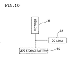
- a float charging system employing a lead acid battery 30 illustrated in FIG. 10 has been employed as an emergency power system.
- DC power is supplied from a rectifier 31 to a DC load 32.
- a constant voltage is kept applied to the lead acid battery 30.
- a self-discharged quantity of energy is charged into the lead acid battery 30. Consequently, the lead acid battery 30 is continually kept in a fully charged condition.
- electric power is supplied from the DC load 32 to the lead storage battery 30.
- the conventional emergency power system can supply electric power to the DC load without momentary outage thereof.
- the conventional emergency power system has drawbacks in that the system requires a large space for placing a lead storage battery therein, because of low energy density thereof, and that thus, this conventional system cannot be installed on a narrow place having limited space.
- the conventional emergency power system has additional drawbacks in that the service life of the lead storage battery is short, that the frequency of replacement of the battery is relatively high, and that the cost thereof is high.
- an object of the invention is to provide a space-saving emergency power system that can be placed on a narrow place having limited space. Further, another object of the invention is to provide a low-cost emergency power system employing a battery that is long in service life and low in frequency of replacement. Moreover, another object of the invention is to provide a system for detecting whether or not a single cell failure occurs in a battery used in an emergency power system.
- an emergency power system that comprises a circuit having a DC load, a rectifier, and a battery, which are electrically connected to one another.
- the circuit is adapted so that normally, DC power is supplied from the rectifier to the DC load, and the battery is charged.
- an emergency such as a power failure, in which an outage of the rectifier occurs, electric power is automatically supplied from the battery to the DC load.
- the battery is a sodium sulfur battery.
- a rectifier output voltage controller for lowering, when the voltage of the sodium sulfur battery reaches a level that is equal to or higher than the predetermined charging voltage, an output voltage of the rectifier thereby to automatically discharge energy from the sodium sulfur battery to the DC load and for raising, when the voltage of the sodium sulfur battery reaches a level that is equal to or lower than the predetermined discharging voltage, an output voltage of the rectifier to thereby charge the sodium sulfur battery is provided between the rectifier and the sodium sulfur battery.
- the predetermined charging voltage and the predetermined discharging voltage of the sodium sulfur battery are within a discharge depth range in the case that the composition of an active material accommodated in a positive electrode chamber of each of sodium sulfur single cells is in a two-phase region.
- the sodium sulfur battery is an assembled battery obtained by constituting strings, each consisting of a predetermined number of series-connected single cells, and then parallel-connecting a predetermined number of strings, and that an output voltage of the rectifier is controlled by monitoring whether or not a module voltage reaches the predetermined charging voltage and whether or not the module voltage reaches the predetermined discharging voltage.
- another emergency power system which comprises a circuit consisting of a DC load, a rectifier and a battery electrically connected to one another and adapted so that normally, DC power is supplied from the rectifier to the DC load at a constant voltage, and the battery is charged, and that in an emergency including a power failure, in which an outage of the rectifier occurs, power is supplied from the battery to the DC load.
- the battery is a sodium sulfur battery.
- a controller having a timer is provided between the rectifier and the sodium sulfur battery and enabled to interrupt or connect an output of the rectifier so that when the current from the sodium sulfur battery reaches a level that is equal to or lower than a predetermined charging current, an output of the rectifier is interrupted, and energy is automatically discharged from the sodium sulfur battery to the DC load for a predetermined period, and that when energy is discharged for the predetermined period, the output of the rectifier is connected to the sodium sulfur battery so as to charge the battery.
- another emergency power system which comprises a circuit consisting of a DC load, a rectifier and a battery electrically connected to one another and adapted so that normally, DC power is supplied from the rectifier to the DC load at a constant voltage, and the battery is charged, and that in an emergency including a power failure, in which an outage of the rectifier occurs, power is supplied from the battery to the DC load.
- the battery is a sodium sulfur battery.
- the power system further comprises a controller enabled to interrupt or connect an output of the rectifier so that when a voltage of said sodium sulfur battery reaches a level that is equal to or higher than a predetermined charging voltage, an output of the rectifier is interrupted, and energy is automatically discharged from the sodium sulfur battery to the DC load, and that when the voltage of the sodium sulfur battery reaches a level that is equal to or lower than a predetermined discharging voltage, the output of the rectifier is connected to the sodium sulfur battery so as to charge the battery.
- a controller enabled to interrupt or connect an output of the rectifier so that when a voltage of said sodium sulfur battery reaches a level that is equal to or higher than a predetermined charging voltage, an output of the rectifier is interrupted, and energy is automatically discharged from the sodium sulfur battery to the DC load, and that when the voltage of the sodium sulfur battery reaches a level that is equal to or lower than a predetermined discharging voltage, the output of the rectifier is connected to the sodium sulfur battery so as to charge the battery.
- another emergency power system which comprises a circuit consisting of a DC load, a rectifier and a battery electrically connected to one another, and also comprising a diode, the forward direction of electrical conduction of which is a direction from the battery to said DC load, and a first switch provided between the rectifier and the sodium sulfur battery.
- This emergency power is adapted so that normally, DC power is supplied from the rectifier to the DC load, and that in an emergency including a power failure, in which an outage of the rectifier occurs, power is supplied from the sodium sulfur battery to the DC load through the diode.
- This emergency power system further comprises a control, provided between the sodium sulfur battery and the first switch, for putting, after discharge in an emergency, the first switch into a connected state and for charging the sodium sulfur battery to a predetermined discharge depth by power supplied from the rectifier, and thereafter interrupting the first switch to thereby hold said sodium sulfur battery in a state in which power from the rectifier is prevented by the diode, the direction of electrical conduction of which is a reverse direction, from being supplied to the battery.
- an embodiment of this emergency power system further comprises another circuit, provided between said circuit consisting of the diode and the first switch electrically parallel-connected and the sodium sulfur battery, for supplying discharging current of the sodium sulfur battery to a heater, and a second switch, provided between the heater and the sodium sulfur battery.
- a temperature control operation is performed by controlling the on/off of the second switch according to the temperature of the sodium sulfur battery under the control of the controller provided among the sodium sulfur battery, the first switch and the second switch.
- the sodium sulfur battery is maintained at a constant discharge depth and at a constant temperature by repeating one cycle consisting of steps of discharging energy from the sodium sulfur battery to the heater, and then charging energy from the rectifier to the sodium sulfur battery at each predetermined time interval under the control of the controller having a timer, and putting the first switch into an interrupted state when the voltage or current of the sodium sulfur battery reaches a level that is equal to or higher than a predetermined voltage, or that is equal to or lower than a predetermined current, thereby stopping charging.
- a detection system for automatically detecting an occurrence of a single cell in a battery used in an emergency power system.
- the detection system comprises a first circuit consisting of a DC load, a rectifier, and a sodium sulfur battery electrically connected to one another, a second circuit consisting of a diode, the forward direction of electrical conduction of which is a direction from the battery to the DC load, and a first switch parallel-connected to each other, a third circuit, provided between the second circuit and the sodium sulfur battery, for supplying a discharging current from the sodium sulfur battery to a heater, and a second switch provided between the heater and the sodium sulfur battery.
- the detection system is adapted so that normally, DC power is supplied from the rectifier to the DC load, and that in an emergency including a power failure, in which an outage of the rectifier occurs, power is supplied from the sodium sulfur battery through the diode to the DC load.
- This detection system further comprises a controller provided among the sodium sulfur battery, the first switch, and the second switch. In this detection system, a temperature control operation is performed by controlling the on/off of the second switch according to a temperature of the sodium sulfur battery by the controller.
- the sodium sulfur battery is maintained at a constant discharge depth and at a constant temperature by repeating one cycle comprising the steps of discharging energy from the sodium sulfur battery to the heater, charging energy from the rectifier to the sodium sulfur battery at each predetermined time interval under the control of the controller, which has a timer, and putting the first switch into an interrupted state and stopping charging when a voltage or current of the sodium sulfur battery reaches a level that is equal to or higher than a predetermined voltage or that is equal to or lower than a predetermined current.
- An emergency power system of the invention features the employment of a sodium sulfur battery as a power storage battery.
- the emergency power system of the invention has a circuit constituted by electrically connecting a rectifier 2, a sodium sulfur battery 1, and a DC load 3 to one another. Normally, DC power is supplied from the rectifier 2 to the DC load 3. Moreover, the sodium sulfur battery 1 is charged. When a power failure occurs, electric power is supplied from the sodium sulfur battery 1 to the DA load 3.
- a controller 4 is provided in the circuit and operative to control the voltage level of the rectifier 2 according to the voltage supplied from the sodium sulfur battery 1.
- the voltage level of the rectifier 2 is lowered at a moment when the voltage level of the sodium sulfur battery 1 reaches a predetermined charging voltage.
- energy is automatically discharged from the sodium sulfur battery 1 to the DC load 3 until the voltage level of the battery 1 reaches a level that is equal to or lower than a predetermined discharging voltage.
- the voltage level of the rectifier 2 is raised.
- the sodium sulfur battery 1 is charged up to the predetermined charging voltage.
- the system of the invention features that an output voltage of the rectifier 2 is controlled so that the sodium sulfur battery 1 is repeatedly and alternatively charged and discharged between the predetermined voltages, in other words, within a constant discharge depth range in the sodium sulfur single cell.
- Item Lead acid Battery MSE Type NAS battery G50kW Chemical Substance Negative Pb Na Electrode PbO 2 S Positive H 2 SO 4 ⁇ -alumina Electrode Electrolytic Solution (Electrolyte) Cell Voltage Nominal 2.0 V 2.075 V Operating Temperature -15 ⁇ 45 °C 280 ⁇ 360 °C Energy Density Wh/kg 32.6 110 Wh/l 66 130 Self-Discharge Rate ⁇ 0.1 %/day (25°C) None Expected Life 7 ⁇ 9 years 15 years Maintenance Maintenance-Free Water Supply, Specific Gravity measurement, Even Charge, Component Replacement Maintenance-Free Efficiency (Initial) Ah Efficiency 90 % 100 % Wh Efficiency 75 % 70 % Internal Resistance 0.10 ⁇ ⁇ Ah 0.7 ⁇ ⁇ Ah Float Charging
- the energy density of the sodium sulfur battery is extremely high and nearly four times that of the lead storage battery. Therefore, the system of the invention employs a sodium sulfur battery as the storage battery. Consequently, the system of the invention can exceedingly save space.
- the float charging cannot be applied to the sodium sulfur battery, differently from the lead storage battery.
- a constant voltage is applied from the rectifier thereto.
- water contained in electrolytic solution is dissolved.
- the charging energy is absorbed thereto, so that the lead storage battery does not malfunction.
- a single cell structure has a positive electrode chamber 8 and a negative electrode chamber 7, which are partitioned off by a bottomed solid electrolyte tube 6 made of ⁇ -alumina.
- a positive electrode conductive material 9 impregnated with sulfur serving as a positive electrode active material is accommodated in the positive electrode chamber 8, while sodium serving as a negative electrode active material is accommodated in the negative electrode chamber 7.
- the single cell is made to operate at 300°C or so.
- sodium is changed into sodium ions that move in the ⁇ -alumina tube 6 and react with sulfur accommodated in the positive electrode to thereby generate sodium polysulfide Na 2 S x .
- the composition of the sodium polysulfide varies with a discharge depth.
- the sodium ions contained in the positive electrode chamber 8 move in the ⁇ -alumina tube 6 and are then returned to the negative electrode chamber 7 as sodium metal.
- a high applied voltage is concentrated on the ⁇ -alumina tube 6. This causes a trouble that the ⁇ -alumina tube 6 is damaged, or that the sodium ions of a ⁇ -alumina crystal move to the negative electrode and thus cannot be maintained.
- discharging similar troubles occur when the discharge is excessively continued.
- the charge and discharge of the sodium sulfur battery are repeated within a discharge depth range in which the battery does not malfunction. It is preferable for preventing an occurrence of a malfunction of the battery that the predetermined charging voltage and the predetermined discharging voltage are those in the case where the composition of the active material accommodated in the positive electrode chamber is in a two-phase region.
- the sodium sulfur battery features that the energy efficiency thereof is relatively high, as compared with the lead storage battery. It is preferable for lowering polarization resistance and enhancing the energy efficiency still more to set the predetermined charging voltage and the predetermined discharging voltage at values in the case that the composition of the active material accommodated in the positive electrode chamber is in the two-phase region.
- the sodium sulfur battery has a long service life, which is twice that of the lead storage battery or more.
- the employment of the sodium sulfur battery can reduce the cost of the emergency power system.
- the sodium sulfur battery is an assembled battery obtained by constituting strings, each of which is obtained by series-connecting a predetermined number of sodium sulfur single cells, and then parallel-connecting a predetermined number of the strings, as illustrated in FIG. 3, and that the system has a controller for controlling the charge and discharge of the sodium sulfur battery by performing the rise and fall of the voltage of the rectifier when the module voltage reaches a predetermined voltage.
- another embodiment of the invention may have a controller for interrupting or connecting an output of the rectifier, instead of the controller for controlling the rise and fall of the voltage of the rectifier when the voltage of the sodium sulfur battery reaches the predetermined charging voltage or the predetermined discharging voltage.
- Electric power is automatically supplied in such an embodiment from the sodium sulfur battery to the DC load by interrupting the output of the rectifier when the voltage of the sodium sulfur battery reaches a level that is equal to or higher than the predetermined charging voltage.
- the output of the rectifier is connected to the battery when the voltage of the sodium sulfur battery becomes lower than the predetermined discharging voltage or lower, the sodium sulfur battery is charged by the rectifier again.
- FIG. 4 is a diagram illustrating the configuration of another embodiment of the invention.
- this embodiment has a circuit in which a DC load 3, a general-purpose rectifier 14, and a sodium sulfur battery 1 are electrically connected to one another.
- a circuit consists of a diode 11, the forward direction of electrical conduction of which is a direction from the sodium sulfur battery 1 to the DC load, and a first switch, which are parallel-connected, and is provided between the general purpose rectifier 14 and the sodium sulfur battery 1.
- DC power is supplied from the general purpose rectifier 14 to the DC load 3.
- electric power is supplied from the sodium sulfur battery 1 to the DC load 3 through the diode 11.
- the first switch 12 After the discharge of the sodium sulfur battery 1 in the emergency, the first switch 12 is put into a connected state by the controller 13 provided between the sodium sulfur battery 1 and this switch 12, so that the sodium sulfur battery 1 is charged to a level, which is equal to or higher than the predetermined charging voltage or current, by supplying electric power from the general purpose rectifier 14 thereto.
- the emergency power system 15 is adapted so that when the voltage level of the battery 1 reaches a level that is equal to or lower than the predetermined charging voltage or current, the first switch 12 is brought into an interrupted state, and that the sodium sulfur battery 1 is maintained in a state in which is no voltage is applied from the general purpose rectifier 14 thereto.
- the emergency power system 15 of this type does not always perform the charge/discharge cycle of the sodium sulfur battery 1.
- This system automatically discharges the sodium sulfur battery 1 to the predetermined discharging voltage, which is the limit, only in an emergency. After the discharge, the system maintains the battery 1 in such a state. At normal times, the system puts the first switch 12 into a connected state to thereby charge the battery 1 to the predetermined voltage.
- the charging operation is manually or automatically performed after an occurrence of a power failure in an emergency.
- the emergency power system of this type has an advantage in that the general purpose rectifier used in the conventional emergency power system can be utilized in this embodiment without no modification.
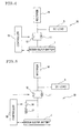
- FIG. 5 is a diagram illustrating another embodiment that is the improvement of the embodiment of the invention illustrated in FIG. 4.
- the embodiment of the invention illustrated in FIG. 5 has a circuit for supplying discharging current to a heater 17, which is provided between the circuit consisting of the diode 11 and the first switch 12, which are parallel-connected, and the sodium sulfur battery 1.
- This embodiment also has a second switch 16 provided between the heater 17 and the sodium sulfur battery 1, and a controller 18, provided between the sodium sulfur battery 1 and each of the first switch 12 and the second switch 16, for controlling the interruption and connection of the switches 12 and 16.
- the on/off of the second switch 16 is controlled according to the temperature of the sodium sulfur battery 1. Then, the temperature is maintained by discharging energy from the sodium sulfur battery 1 to the heater 17.
- the controller 18 having a timer causes the general purpose rectifier 14 at each predetermined time interval to charge the sodium sulfur battery 1.
- the first switch 12 is put into an interrupted state. Then, the battery 1 is charged. This process is employed as one cycle.
- the emergency power system 19 features that the sodium sulfur battery 1 is maintained at a constant discharge depth and at a constant temperature by repeating this cycle.
- the emergency power system of this type has advantages in that whether or a malfunction of a single cell occurs can be always monitored and the functions thereof including the self-diagnostic function can be always maintained because electric current is fed to and flows through the heater, in addition to the advantage that the rectifier used in the conventional emergency power system using the lead storage battery can be used therein without modification.
- the emergency power system of this type has another advantage in that the heater can be used as a heat reserving heater for the sodium sulfur battery.
- FIGS. 6 and 7 illustrate the characteristics and operations of this embodiment that uses the circuit shown in FIG. 1 and is adapted to repeat the charge/discharge of the sodium sulfur battery by controlling the output voltage of the rectifier and also repeat the charge/discharge of a sodium sulfur single cell in a range between the constant discharge depths.
- the predetermined charging voltage was 2.17 V. Further, the predetermined discharging voltage was 1.98 V. The discharge depth was 100 Ah to 350 Ah. The discharging current was 73A. The charging current was 64A. Furthermore, the total energy capacity and the charge capacity of each of the cells of the sodium sulfur battery are 62.4 kWh and 600 Ah/52 cells, respectively.
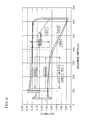
- FIGS. 8 and 9 illustrate the characteristics and operations of this embodiment that uses the circuit shown in FIG. 5 and is adapted to control the on/off of the second switch according to the temperature of the sodium sulfur battery and to maintain the temperature by discharging energy from the sodium sulfur battery to the heater, and to uses the controller having a timer, which causes the general purpose rectifier at each predetermined time interval to charge the sodium sulfur battery, and to establish a process as one cycle consisting of steps of putting the first switch into an interrupted state when the voltage of the charged battery reaches a level that is equal to or higher than the predetermined voltage or that is equal to or lower than the predetermined current, and of then charging the battery and to also repeat this cycle thereby maintaining the sodium sulfur battery 1 at a constant discharge depth and at a constant temperature and also repeat the charge/discharge of the sodium sulfur single cell in a range between the constant discharge depths.
- the predetermined charging voltage was 2.17 V. Further, the predetermined discharging voltage was 1.98 V. The discharge depth was 100 Ah to 350 Ah. The discharging current was 73A. The charging current was 64A. Furthermore, the total energy capacity and the charge capacity of each of the cells of the sodium sulfur battery are 62.4 kWh and 600 Ah/52 cells, respectively.
- the emergency power system of the invention can save space and achieve long service life thereof and reduce the maintenance cost thereof. Thus, a low-cost emergency power system is realized. Further, the system for automatically detecting an occurrence of a single cell failure in the battery used in the emergency power system of the invention has a self-diagnostic function of self-diagnosing a storage battery fault. Thus, the emergency power system of the invention has an advantage in that the function of serving as an emergency power supply can be maintained at all times.
Landscapes
- Business, Economics & Management (AREA)
- Emergency Management (AREA)
- Engineering & Computer Science (AREA)
- Power Engineering (AREA)
- Secondary Cells (AREA)
- Stand-By Power Supply Arrangements (AREA)
- Charge And Discharge Circuits For Batteries Or The Like (AREA)
- Emergency Alarm Devices (AREA)
- Compositions Of Oxide Ceramics (AREA)
Abstract
Description
- The present invention generally relates to an emergency power system, and to a system for automatically detecting whether not a failure of a single cell occurs in a battery for use in the system.
- Hitherto, a float charging system employing a
lead acid battery 30 illustrated in FIG. 10 has been employed as an emergency power system. Ordinarily, DC power is supplied from arectifier 31 to aDC load 32. Moreover, a constant voltage is kept applied to thelead acid battery 30. Thus, a self-discharged quantity of energy is charged into thelead acid battery 30. Consequently, thelead acid battery 30 is continually kept in a fully charged condition. In the case of emergency, for example, in the event of an outage of therectifier 31, electric power is supplied from theDC load 32 to thelead storage battery 30. Thus, in the case of emergency, for instance, in the even of a power failure, the conventional emergency power system can supply electric power to the DC load without momentary outage thereof. - However, the conventional emergency power system has drawbacks in that the system requires a large space for placing a lead storage battery therein, because of low energy density thereof, and that thus, this conventional system cannot be installed on a narrow place having limited space. Moreover, the conventional emergency power system has additional drawbacks in that the service life of the lead storage battery is short, that the frequency of replacement of the battery is relatively high, and that the cost thereof is high.
- The invention is accomplished in view of the aforementioned drawbacks. Accordingly, an object of the invention is to provide a space-saving emergency power system that can be placed on a narrow place having limited space. Further, another object of the invention is to provide a low-cost emergency power system employing a battery that is long in service life and low in frequency of replacement. Moreover, another object of the invention is to provide a system for detecting whether or not a single cell failure occurs in a battery used in an emergency power system.
- To achieve the foregoing objects, according to an aspect of the invention, there is provided an emergency power system that comprises a circuit having a DC load, a rectifier, and a battery, which are electrically connected to one another. The circuit is adapted so that normally, DC power is supplied from the rectifier to the DC load, and the battery is charged. In an emergency, such as a power failure, in which an outage of the rectifier occurs, electric power is automatically supplied from the battery to the DC load. In this system, the battery is a sodium sulfur battery.
- Further, in an embodiment of the invention, preferably, a rectifier output voltage controller for lowering, when the voltage of the sodium sulfur battery reaches a level that is equal to or higher than the predetermined charging voltage, an output voltage of the rectifier thereby to automatically discharge energy from the sodium sulfur battery to the DC load and for raising, when the voltage of the sodium sulfur battery reaches a level that is equal to or lower than the predetermined discharging voltage, an output voltage of the rectifier to thereby charge the sodium sulfur battery is provided between the rectifier and the sodium sulfur battery.
- Further, in an embodiment of the emergency power system of the invention, preferably, the predetermined charging voltage and the predetermined discharging voltage of the sodium sulfur battery are within a discharge depth range in the case that the composition of an active material accommodated in a positive electrode chamber of each of sodium sulfur single cells is in a two-phase region.
- Further, in an embodiment of the invention, it is preferable that the sodium sulfur battery is an assembled battery obtained by constituting strings, each consisting of a predetermined number of series-connected single cells, and then parallel-connecting a predetermined number of strings, and that an output voltage of the rectifier is controlled by monitoring whether or not a module voltage reaches the predetermined charging voltage and whether or not the module voltage reaches the predetermined discharging voltage.
- Furthermore, preferably, an embodiment of the invention detects an occurrence of a malfunction of a single cell according to whether or not the difference ΔV (=Vocv - Vm) between the no-load module open circuit voltage Vocv and the constant-resistance-load module voltage Vm is larger than an initially determined normal voltage difference ΔVn (that is, ΔV>ΔVn), and generates an alarm when a malfunction of a single cell occurs, thereby to always maintain the function thereof serving as an emergency power system.
- This is because of the facts that the voltage difference in the case of occurrence of no malfunction ΔV = I·R where I is module current, and R is module resistance. Thus, when a malfunction of a single cell occurs, the resistance R rises, and that thus the voltage difference ΔV increases.
- According to the invention, there is provided another emergency power system, which comprises a circuit consisting of a DC load, a rectifier and a battery electrically connected to one another and adapted so that normally, DC power is supplied from the rectifier to the DC load at a constant voltage, and the battery is charged, and that in an emergency including a power failure, in which an outage of the rectifier occurs, power is supplied from the battery to the DC load. In this system, the battery is a sodium sulfur battery. A controller having a timer is provided between the rectifier and the sodium sulfur battery and enabled to interrupt or connect an output of the rectifier so that when the current from the sodium sulfur battery reaches a level that is equal to or lower than a predetermined charging current, an output of the rectifier is interrupted, and energy is automatically discharged from the sodium sulfur battery to the DC load for a predetermined period, and that when energy is discharged for the predetermined period, the output of the rectifier is connected to the sodium sulfur battery so as to charge the battery.
- According to the invention, there is provided another emergency power system, which comprises a circuit consisting of a DC load, a rectifier and a battery electrically connected to one another and adapted so that normally, DC power is supplied from the rectifier to the DC load at a constant voltage, and the battery is charged, and that in an emergency including a power failure, in which an outage of the rectifier occurs, power is supplied from the battery to the DC load. In this system, the battery is a sodium sulfur battery. The power system further comprises a controller enabled to interrupt or connect an output of the rectifier so that when a voltage of said sodium sulfur battery reaches a level that is equal to or higher than a predetermined charging voltage, an output of the rectifier is interrupted, and energy is automatically discharged from the sodium sulfur battery to the DC load, and that when the voltage of the sodium sulfur battery reaches a level that is equal to or lower than a predetermined discharging voltage, the output of the rectifier is connected to the sodium sulfur battery so as to charge the battery.
- According to the invention, there is provided another emergency power system, which comprises a circuit consisting of a DC load, a rectifier and a battery electrically connected to one another, and also comprising a diode, the forward direction of electrical conduction of which is a direction from the battery to said DC load, and a first switch provided between the rectifier and the sodium sulfur battery. This emergency power is adapted so that normally, DC power is supplied from the rectifier to the DC load, and that in an emergency including a power failure, in which an outage of the rectifier occurs, power is supplied from the sodium sulfur battery to the DC load through the diode. This emergency power system further comprises a control, provided between the sodium sulfur battery and the first switch, for putting, after discharge in an emergency, the first switch into a connected state and for charging the sodium sulfur battery to a predetermined discharge depth by power supplied from the rectifier, and thereafter interrupting the first switch to thereby hold said sodium sulfur battery in a state in which power from the rectifier is prevented by the diode, the direction of electrical conduction of which is a reverse direction, from being supplied to the battery.
- Incidentally, in this emergency power system, practical means for putting the first switch into a connected state to thereby charge the sodium sulfur battery to a predetermined discharge depth by supplying power from the rectifier is enabled to perform the charging until a charging current reaches a level that is equal to or lower than a set current, or until a module voltage is equal to or lower than a predetermined voltage. It is preferable for reducing a discharge starting voltage drop in an emergency that upon completion of charging, the discharge depth is increased by discharging a predetermined quantity of electricity (20 to 40 Ah).
- Further, an embodiment of this emergency power system further comprises another circuit, provided between said circuit consisting of the diode and the first switch electrically parallel-connected and the sodium sulfur battery, for supplying discharging current of the sodium sulfur battery to a heater, and a second switch, provided between the heater and the sodium sulfur battery. In this system, a temperature control operation is performed by controlling the on/off of the second switch according to the temperature of the sodium sulfur battery under the control of the controller provided among the sodium sulfur battery, the first switch and the second switch. The sodium sulfur battery is maintained at a constant discharge depth and at a constant temperature by repeating one cycle consisting of steps of discharging energy from the sodium sulfur battery to the heater, and then charging energy from the rectifier to the sodium sulfur battery at each predetermined time interval under the control of the controller having a timer, and putting the first switch into an interrupted state when the voltage or current of the sodium sulfur battery reaches a level that is equal to or higher than a predetermined voltage, or that is equal to or lower than a predetermined current, thereby stopping charging.
- According to the invention, there is provided a detection system for automatically detecting an occurrence of a single cell in a battery used in an emergency power system. The detection system comprises a first circuit consisting of a DC load, a rectifier, and a sodium sulfur battery electrically connected to one another, a second circuit consisting of a diode, the forward direction of electrical conduction of which is a direction from the battery to the DC load, and a first switch parallel-connected to each other, a third circuit, provided between the second circuit and the sodium sulfur battery, for supplying a discharging current from the sodium sulfur battery to a heater, and a second switch provided between the heater and the sodium sulfur battery. The detection system is adapted so that normally, DC power is supplied from the rectifier to the DC load, and that in an emergency including a power failure, in which an outage of the rectifier occurs, power is supplied from the sodium sulfur battery through the diode to the DC load. This detection system further comprises a controller provided among the sodium sulfur battery, the first switch, and the second switch. In this detection system, a temperature control operation is performed by controlling the on/off of the second switch according to a temperature of the sodium sulfur battery by the controller. The sodium sulfur battery is maintained at a constant discharge depth and at a constant temperature by repeating one cycle comprising the steps of discharging energy from the sodium sulfur battery to the heater, charging energy from the rectifier to the sodium sulfur battery at each predetermined time interval under the control of the controller, which has a timer, and putting the first switch into an interrupted state and stopping charging when a voltage or current of the sodium sulfur battery reaches a level that is equal to or higher than a predetermined voltage or that is equal to or lower than a predetermined current. Thus, an occurrence of a malfunction of a single cell in the sodium sulfur battery is automatically detected by monitoring a discharging current during energy is discharged from the sodium sulfur battery to the heater.
- Other features, objects and advantages of the present invention will become apparent from the following description of preferred embodiments with reference to the drawings in which like reference characters designate like or corresponding parts throughout several views, and in which:
- FIG. 1 is a diagram illustrating an embodiment of an emergency power system of the invention;
- FIG. 2 is a schematic diagram illustrating the structure of a sodium sulfur battery;
- FIG. 3 is a diagram illustrating an example of a sodium sulfur battery;
- FIG. 4 is a diagram illustrating another embodiment of the emergency power system of the invention;
- FIG. 5 is a diagram illustrating another example of the improvement of the embodiment of the emergency power system of the present invention;
- FIG. 6 is a diagram illustrating an example of charge/discharge characteristics of a sodium sulfur single cell of the emergency power system of the invention;
- FIG. 7 is a diagram illustrating an example of the relation among the charging voltage, the discharging voltage, and the depth of charge and discharge of a sodium sulfur single cell of the emergency power system of the invention;
- FIG. 8 is a diagram illustrating another example of charge/discharge characteristics of a sodium sulfur single cell of the emergency power system of the invention;
- FIG. 9 is a diagram illustrating an example of the relation among the charging voltage, the discharging voltage, and the depth of charge and discharge of a sodium sulfur single cell of the emergency power system of the invention; and
- FIG. 10 is a diagram illustrating a conventional emergency power system.
-
- Hereinafter, the preferred embodiments of the invention will be described in detail by referring to the accompanying drawings. However, needless to say, the invention is not limited to the following embodiments.
- An emergency power system of the invention features the employment of a sodium sulfur battery as a power storage battery.
- As illustrated in FIG. 1, the emergency power system of the invention has a circuit constituted by electrically connecting a
rectifier 2, asodium sulfur battery 1, and aDC load 3 to one another. Normally, DC power is supplied from therectifier 2 to theDC load 3. Moreover, thesodium sulfur battery 1 is charged. When a power failure occurs, electric power is supplied from thesodium sulfur battery 1 to theDA load 3. - At ordinary times, the charging of the
sodium sulfur battery 1 by therectifier 2 is performed until the voltage level of thesodium sulfur battery 1 reaches a level that is equal to or higher than a predetermined level. Acontroller 4 is provided in the circuit and operative to control the voltage level of therectifier 2 according to the voltage supplied from thesodium sulfur battery 1. The voltage level of therectifier 2 is lowered at a moment when the voltage level of thesodium sulfur battery 1 reaches a predetermined charging voltage. Then, energy is automatically discharged from thesodium sulfur battery 1 to theDC load 3 until the voltage level of thebattery 1 reaches a level that is equal to or lower than a predetermined discharging voltage. At a moment at which thebattery 1 reaches the predetermined discharging voltage, the voltage level of therectifier 2 is raised. Thus, thesodium sulfur battery 1 is charged up to the predetermined charging voltage. - The system of the invention features that an output voltage of the
rectifier 2 is controlled so that thesodium sulfur battery 1 is repeatedly and alternatively charged and discharged between the predetermined voltages, in other words, within a constant discharge depth range in the sodium sulfur single cell.Item Lead acid Battery MSE Type NAS battery G50kW Chemical Substance Negative Pb Na Electrode PbO2 S Positive H2SO4 β-alumina Electrode Electrolytic Solution (Electrolyte) Cell Voltage Nominal 2.0 V 2.075 V Operating Temperature -15 ∼ 45 °C 280 ∼ 360 °C Energy Density Wh/kg 32.6 110 Wh/l 66 130 Self-Discharge Rate ≤0.1 %/day (25°C) None Expected Life 7 ∼ 9 years 15 years Maintenance Maintenance-Free Water Supply, Specific Gravity measurement, Even Charge, Component Replacement Maintenance-Free Efficiency (Initial) Ah Efficiency 90 % 100 % Wh Efficiency 75 % 70 % Internal
Resistance0.10 Ω · Ah 0.7 Ω · Ah Float Charging Permitted (When Not Performed, Capacity Is Reduced Due to Accidental Discharge) Protection Circuit Is Needed (Checking Is Needed) Merits · Immediate Utilization Possible
· Room Temperature Operation Possible
· Float Charging· High Energy Density
· No Self-Discharge
· High Energy EfficiencyPossible Defects · Low Energy Density
· High Self-Discharge Rate
· Short Life
· Generation of Hydrogen by Overcharge
· Low Energy Efficiency· Temperature Rising Needed
· High Temperature Operation
· Heat Reserving Power Is Needed during Unused
· Float Charging Impossible
· High Internal Resistance - As is seen from TABLE 1 for making the comparison between the sodium sulfur battery and the lead storage battery, the energy density of the sodium sulfur battery is extremely high and nearly four times that of the lead storage battery. Therefore, the system of the invention employs a sodium sulfur battery as the storage battery. Consequently, the system of the invention can exceedingly save space.
- However, the float charging cannot be applied to the sodium sulfur battery, differently from the lead storage battery. In the case of the lead storage battery, a constant voltage is applied from the rectifier thereto. Thus, even when the lead storage battery is continuously charged in a fully charged state, water contained in electrolytic solution is dissolved. Thus, the charging energy is absorbed thereto, so that the lead storage battery does not malfunction.
- In contrast, in the sodium sulfur battery, as illustrated in FIG. 2, a single cell structure has a
positive electrode chamber 8 and anegative electrode chamber 7, which are partitioned off by a bottomedsolid electrolyte tube 6 made of β-alumina. A positive electrodeconductive material 9 impregnated with sulfur serving as a positive electrode active material is accommodated in thepositive electrode chamber 8, while sodium serving as a negative electrode active material is accommodated in thenegative electrode chamber 7. The single cell is made to operate at 300°C or so. Further, when discharged, sodium is changed into sodium ions that move in the β-alumina tube 6 and react with sulfur accommodated in the positive electrode to thereby generate sodium polysulfide Na2Sx. Incidentally, the composition of the sodium polysulfide varies with a discharge depth. - On the other hand, in the case of charging, the sodium ions contained in the
positive electrode chamber 8 move in the β-alumina tube 6 and are then returned to thenegative electrode chamber 7 as sodium metal. In the case that the charging is still continued in a state in which sodium ions in thepositive electrode chamber 8 are extremely reduced, a high applied voltage is concentrated on the β-alumina tube 6. This causes a trouble that the β-alumina tube 6 is damaged, or that the sodium ions of a β-alumina crystal move to the negative electrode and thus cannot be maintained. In the case of discharging, similar troubles occur when the discharge is excessively continued. - Thus, according to the invention, the charge and discharge of the sodium sulfur battery are repeated within a discharge depth range in which the battery does not malfunction. It is preferable for preventing an occurrence of a malfunction of the battery that the predetermined charging voltage and the predetermined discharging voltage are those in the case where the composition of the active material accommodated in the positive electrode chamber is in a two-phase region.
- Further, as described in TABLE 1, the sodium sulfur battery features that the energy efficiency thereof is relatively high, as compared with the lead storage battery. It is preferable for lowering polarization resistance and enhancing the energy efficiency still more to set the predetermined charging voltage and the predetermined discharging voltage at values in the case that the composition of the active material accommodated in the positive electrode chamber is in the two-phase region.
- Moreover, as described in TABLE 1, the sodium sulfur battery has a long service life, which is twice that of the lead storage battery or more. Thus, the employment of the sodium sulfur battery can reduce the cost of the emergency power system.
- Further, it is preferable for preventing an occurrence of a malfunction of a single cell that the sodium sulfur battery is an assembled battery obtained by constituting strings, each of which is obtained by series-connecting a predetermined number of sodium sulfur single cells, and then parallel-connecting a predetermined number of the strings, as illustrated in FIG. 3, and that the system has a controller for controlling the charge and discharge of the sodium sulfur battery by performing the rise and fall of the voltage of the rectifier when the module voltage reaches a predetermined voltage.
- Furthermore, it is preferable for always maintaining the functions of the emergency power system that an occurrence of a malfunction of a single cell is detected by monitoring whether or not the difference ΔV (= Vocv - Vm) between a no-load module open circuit voltage Vocv, a constant-resistance-load module voltage Vm and a normal voltage difference ΔVn meet the condition ΔV>▵Vn, and that an alarm is generated when a malfunction of a single cell occurs.
- Further, another embodiment of the invention may have a controller for interrupting or connecting an output of the rectifier, instead of the controller for controlling the rise and fall of the voltage of the rectifier when the voltage of the sodium sulfur battery reaches the predetermined charging voltage or the predetermined discharging voltage.
- Electric power is automatically supplied in such an embodiment from the sodium sulfur battery to the DC load by interrupting the output of the rectifier when the voltage of the sodium sulfur battery reaches a level that is equal to or higher than the predetermined charging voltage. In the case that the output of the rectifier is connected to the battery when the voltage of the sodium sulfur battery becomes lower than the predetermined discharging voltage or lower, the sodium sulfur battery is charged by the rectifier again. Thus, a space-saving emergency power system is realized without a malfunction of the sodium sulfur battery by having a controller for monitoring the charging and discharging voltages of the sodium sulfur battery and for interrupting or connecting the output of the rectifier.
- FIG. 4 is a diagram illustrating the configuration of another embodiment of the invention. As shown in FIG. 4, this embodiment has a circuit in which a
DC load 3, a general-purpose rectifier 14, and asodium sulfur battery 1 are electrically connected to one another. Moreover, a circuit consists of adiode 11, the forward direction of electrical conduction of which is a direction from thesodium sulfur battery 1 to the DC load, and a first switch, which are parallel-connected, and is provided between thegeneral purpose rectifier 14 and thesodium sulfur battery 1. At ordinary times, DC power is supplied from thegeneral purpose rectifier 14 to theDC load 3. In an emergency, such as an outage of thegeneral purpose rectifier 14 at a power failure, electric power is supplied from thesodium sulfur battery 1 to theDC load 3 through thediode 11. - After the discharge of the
sodium sulfur battery 1 in the emergency, thefirst switch 12 is put into a connected state by thecontroller 13 provided between thesodium sulfur battery 1 and thisswitch 12, so that thesodium sulfur battery 1 is charged to a level, which is equal to or higher than the predetermined charging voltage or current, by supplying electric power from thegeneral purpose rectifier 14 thereto. Theemergency power system 15 is adapted so that when the voltage level of thebattery 1 reaches a level that is equal to or lower than the predetermined charging voltage or current, thefirst switch 12 is brought into an interrupted state, and that thesodium sulfur battery 1 is maintained in a state in which is no voltage is applied from thegeneral purpose rectifier 14 thereto. - The
emergency power system 15 of this type does not always perform the charge/discharge cycle of thesodium sulfur battery 1. This system automatically discharges thesodium sulfur battery 1 to the predetermined discharging voltage, which is the limit, only in an emergency. After the discharge, the system maintains thebattery 1 in such a state. At normal times, the system puts thefirst switch 12 into a connected state to thereby charge thebattery 1 to the predetermined voltage. The charging operation is manually or automatically performed after an occurrence of a power failure in an emergency. - The emergency power system of this type has an advantage in that the general purpose rectifier used in the conventional emergency power system can be utilized in this embodiment without no modification.
- FIG. 5 is a diagram illustrating another embodiment that is the improvement of the embodiment of the invention illustrated in FIG. 4. The embodiment of the invention illustrated in FIG. 5 has a circuit for supplying discharging current to a
heater 17, which is provided between the circuit consisting of thediode 11 and thefirst switch 12, which are parallel-connected, and thesodium sulfur battery 1. This embodiment also has asecond switch 16 provided between theheater 17 and thesodium sulfur battery 1, and acontroller 18, provided between thesodium sulfur battery 1 and each of thefirst switch 12 and thesecond switch 16, for controlling the interruption and connection of theswitches - In such a circuit, the on/off of the
second switch 16 is controlled according to the temperature of thesodium sulfur battery 1. Then, the temperature is maintained by discharging energy from thesodium sulfur battery 1 to theheater 17. Thecontroller 18 having a timer causes thegeneral purpose rectifier 14 at each predetermined time interval to charge thesodium sulfur battery 1. When the voltage of the charged battery reaches a level that is equal to or higher than the predetermined voltage or that is equal to or lower than the predetermined current, thefirst switch 12 is put into an interrupted state. Then, thebattery 1 is charged. This process is employed as one cycle. Theemergency power system 19 features that thesodium sulfur battery 1 is maintained at a constant discharge depth and at a constant temperature by repeating this cycle. - The emergency power system of this type has advantages in that whether or a malfunction of a single cell occurs can be always monitored and the functions thereof including the self-diagnostic function can be always maintained because electric current is fed to and flows through the heater, in addition to the advantage that the rectifier used in the conventional emergency power system using the lead storage battery can be used therein without modification.
- Furthermore, the emergency power system of this type has another advantage in that the heater can be used as a heat reserving heater for the sodium sulfur battery.
- Hereinafter, the embodiments of the invention are described.
- FIGS. 6 and 7 illustrate the characteristics and operations of this embodiment that uses the circuit shown in FIG. 1 and is adapted to repeat the charge/discharge of the sodium sulfur battery by controlling the output voltage of the rectifier and also repeat the charge/discharge of a sodium sulfur single cell in a range between the constant discharge depths.
- In the case of the single cell operated at an operating temperature of 320°C, the predetermined charging voltage was 2.17 V. Further, the predetermined discharging voltage was 1.98 V. The discharge depth was 100 Ah to 350 Ah. The discharging current was 73A. The charging current was 64A. Furthermore, the total energy capacity and the charge capacity of each of the cells of the sodium sulfur battery are 62.4 kWh and 600 Ah/52 cells, respectively.
- FIGS. 8 and 9 illustrate the characteristics and operations of this embodiment that uses the circuit shown in FIG. 5 and is adapted to control the on/off of the second switch according to the temperature of the sodium sulfur battery and to maintain the temperature by discharging energy from the sodium sulfur battery to the heater, and to uses the controller having a timer, which causes the general purpose rectifier at each predetermined time interval to charge the sodium sulfur battery, and to establish a process as one cycle consisting of steps of putting the first switch into an interrupted state when the voltage of the charged battery reaches a level that is equal to or higher than the predetermined voltage or that is equal to or lower than the predetermined current, and of then charging the battery and to also repeat this cycle thereby maintaining the
sodium sulfur battery 1 at a constant discharge depth and at a constant temperature and also repeat the charge/discharge of the sodium sulfur single cell in a range between the constant discharge depths. - In the case of the single cell operated at an operating temperature of 320°C, the predetermined charging voltage was 2.17 V. Further, the predetermined discharging voltage was 1.98 V. The discharge depth was 100 Ah to 350 Ah. The discharging current was 73A. The charging current was 64A. Furthermore, the total energy capacity and the charge capacity of each of the cells of the sodium sulfur battery are 62.4 kWh and 600 Ah/52 cells, respectively.
- As described above, the emergency power system of the invention can save space and achieve long service life thereof and reduce the maintenance cost thereof. Thus, a low-cost emergency power system is realized. Further, the system for automatically detecting an occurrence of a single cell failure in the battery used in the emergency power system of the invention has a self-diagnostic function of self-diagnosing a storage battery fault. Thus, the emergency power system of the invention has an advantage in that the function of serving as an emergency power supply can be maintained at all times.
- Although the preferred embodiments of the present invention have been described above, it should be understood that the present invention is not limited thereto and that other modifications will be apparent to those skilled in the art without departing from the sprint of the invention.
- The scope of the present invention, therefore, should be determined solely by the appended claims.
Claims (10)
- An emergency power system comprising a circuit having a DC load, a rectifier, and a battery, which are electrically connected to one another,
wherein said circuit is adapted so that normally, DC power is supplied from said rectifier to said DC load, and said battery is charged, and that in an emergency including a power failure, in which an outage of said rectifier occurs, electric power is automatically supplied from said battery to said DC load, wherein said battery is a sodium sulfur battery. - An emergency power system according to claim 1, which further comprises a rectifier output voltage controller for lowering, when a voltage of said sodium sulfur battery reaches a level that is equal to or higher than a predetermined charging voltage, an output voltage of said rectifier thereby to automatically discharge energy from said sodium sulfur battery to said DC load and for raising, when the voltage of said sodium sulfur battery reaches a level that is equal to or lower than a predetermined discharging voltage, an output voltage of said rectifier to thereby charge said sodium sulfur battery, which controller is provided between said rectifier and said sodium sulfur battery.
- An emergency power system according to claim 2, wherein the predetermined charging voltage and the predetermined discharging voltage of said sodium sulfur battery are within a discharge depth range in a case that composition of an active material accommodated in a positive electrode chamber of each of sodium sulfur single cells is in a two-phase region.
- An emergency power system according to claim 2, wherein said sodium sulfur battery is an assembled battery obtained by constituting strings, each consisting of a predetermined number of series-connected single cells, and then parallel-connecting a predetermined number of strings, and wherein an output voltage of the rectifier is controlled by monitoring whether or not a module voltage reaches the predetermined charging voltage and whether or not the module voltage reaches the predetermined discharging voltage.
- An emergency power system according to claim 4, wherein an occurrence of a malfunction of a single cell is detected according to whether or not a difference between a no-load module open circuit voltage and a constant-resistance-load module voltage is larger than an initially determined normal voltage difference, and an alarm is generated at an occurrence of a malfunction of a single cell, thereby always maintaining a function of serving as an emergency power system.
- An emergency power system comprising a circuit consisting of a DC load, a rectifier and a battery electrically connected to one another and adapted so that normally, DC power is supplied from said rectifier to said DC load at a constant voltage, and said battery is charged, and that in an emergency including a power failure, in which an outage of said rectifier occurs, power is supplied from said battery to said DC load,
wherein said battery is a sodium sulfur battery, and wherein a controller having a timer is provided between said rectifier and said sodium sulfur battery and enabled to interrupt or connect an output of said rectifier so that when electric current from said sodium sulfur battery reaches a level that is equal to or lower than a predetermined charging current, an output of said rectifier is interrupted, and energy is automatically discharged from said sodium sulfur battery to said DC load for a predetermined period, and that when energy is discharged for said predetermined period, the output of said rectifier is connected to said sodium sulfur battery so as to charge said battery. - An emergency power system comprising a circuit consisting of a DC load, a rectifier and a battery electrically connected to one another and adapted so that normally, DC power is supplied from said rectifier to said DC load at a constant voltage, and said battery is charged, and that in an emergency including a power failure, in which an outage of said rectifier occurs, power is supplied from said battery to said DC load, wherein said battery is a sodium sulfur battery,
said power system further comprising a controller enabled to interrupt or connect an output of said rectifier so that when a voltage of said sodium sulfur battery reaches a level that is equal to or higher than a predetermined charging voltage, an output of said rectifier is interrupted, and energy is automatically discharged from said sodium sulfur battery to said DC load, and that when the voltage of said sodium sulfur battery reaches a level that is equal to or lower than a predetermined discharging voltage, the output of said rectifier is connected to said sodium sulfur battery so as to charge said battery. - An emergency power system comprising a circuit consisting of a DC load, a rectifier and a battery electrically connected to one another, and also comprising a diode, the forward direction of electrical conduction of which is a direction from said battery to said DC load, and a first switch provided between said rectifier and said sodium sulfur battery, said emergency power adapted so that normally, DC power is supplied from said rectifier to said DC load, and that in an emergency including a power failure, in which an outage of said rectifier occurs, power is supplied from said sodium sulfur battery to said DC load through said diode,
said emergency power system further comprising:
a control, provided between said sodium sulfur battery and said first switch, for putting, after discharge in an emergency, said first switch into a connected state and for charging said sodium sulfur battery to a predetermined discharge depth by power supplied from said rectifier, and thereafter interrupting said first switch to thereby hold said sodium sulfur battery in a state in which power from said rectifier is prevented by said diode, the direction of electrical conduction of which is a reverse direction, from being supplied to said battery. - An emergency power system according to claim 8, which further comprises:another circuit, provided between said circuit consisting of said diode and said first switch electrically parallel-connected and said sodium sulfur battery, for supplying discharging current of said sodium sulfur battery to a heater; anda second switch, provided between said heater and said sodium sulfur battery,wherein a temperature control operation is performed by controlling on/off of said second switch according to a temperature of said sodium sulfur battery under the control of said controller provided among said sodium sulfur battery, said first switch and said second switch, wherein said sodium sulfur battery is maintained at a constant discharge depth and at a constant temperature by repeating one cycle consisting of steps of discharging energy from said sodium sulfur battery to said heater, and then charging energy from said rectifier to said sodium sulfur battery at each predetermined time interval under the control of said controller having a timer, and putting said first switch into an interrupted state when a voltage or current of said sodium sulfur battery reaches a level that is equal to or higher than a predetermined voltage, or that is equal to or lower than a predetermined current, thereby stopping charging.
- A detection system for automatically detecting an occurrence of a single cell in a battery used in an emergency power system, said detection system comprising:a first circuit consisting of a DC load, a rectifier, and a sodium sulfur battery electrically connected to one another;a second circuit consisting of a diode, the forward direction of electrical conduction of which is a direction from said battery to said DC load, and a first switch parallel-connected to each other;a third circuit, provided between said second circuit and said sodium sulfur battery, for supplying a discharging current from said sodium sulfur battery to a heater; anda second switch provided between said heater and said sodium sulfur battery,said detection system being adapted so that normally, DC power is supplied from said rectifier to said DC load, and that in an emergency including a power failure, in which an outage of said rectifier occurs, power is supplied from said sodium sulfur battery through said diode to said DC load,said detection system further comprising:
a controller provided among said sodium sulfur battery, said first switch, and said second switch, wherein a temperature control operation is performed by controlling on and off operations of said second switch according to a temperature of said sodium sulfur battery by said controller, wherein said sodium sulfur battery is maintained at a constant discharge depth and at a constant temperature by repeating one cycle comprising the steps of discharging energy from said sodium sulfur battery to said heater, charging energy from said rectifier to said sodium sulfur battery at each predetermined time interval under the control of said controller, which has a timer, and putting said first switch into an interrupted state and stopping charging when a voltage or current of said sodium sulfur battery reaches a level that is equal to or higher than a predetermined voltage or that is equal to or lower than a predetermined current, and wherein an occurrence of a malfunction of a single cell in said sodium sulfur battery is automatically detected by monitoring a discharging current during energy is discharged from said sodium sulfur battery to said heater.
Applications Claiming Priority (2)
| Application Number | Priority Date | Filing Date | Title |
|---|---|---|---|
| JP2000089333 | 2000-03-28 | ||
| JP2000089333A JP3505124B2 (en) | 2000-03-28 | 2000-03-28 | Emergency power supply system and system for automatically detecting the presence or absence of failure of a single cell in a battery used in the system |
Publications (3)
| Publication Number | Publication Date |
|---|---|
| EP1143595A2 true EP1143595A2 (en) | 2001-10-10 |
| EP1143595A3 EP1143595A3 (en) | 2004-04-28 |
| EP1143595B1 EP1143595B1 (en) | 2008-05-28 |
Family
ID=18605103
Family Applications (1)
| Application Number | Title | Priority Date | Filing Date |
|---|---|---|---|
| EP01302784A Expired - Lifetime EP1143595B1 (en) | 2000-03-28 | 2001-03-26 | Emergency power system |
Country Status (5)
| Country | Link |
|---|---|
| US (1) | US6577103B2 (en) |
| EP (1) | EP1143595B1 (en) |
| JP (1) | JP3505124B2 (en) |
| AT (1) | ATE397312T1 (en) |
| DE (1) | DE60134187D1 (en) |
Cited By (4)
| Publication number | Priority date | Publication date | Assignee | Title |
|---|---|---|---|---|
| EP2157654A1 (en) * | 2008-08-20 | 2010-02-24 | Ngk Insulators, Ltd. | Heater power supply method of sodium-sulfer battery |
| WO2013027638A1 (en) * | 2011-08-19 | 2013-02-28 | Ngk Insulators, Ltd. | Method of controlling storage battery, apparatus for controlling storage battery, and electric power control system |
| CN101541125B (en) * | 2008-03-20 | 2013-06-19 | 高伟林 | LED illumination emergency lamp circuit and LED lamp using circuit |
| EP2698897A4 (en) * | 2011-04-11 | 2015-06-10 | Ngk Insulators Ltd | Power storage device and method for operating power storage device |
Families Citing this family (21)
| Publication number | Priority date | Publication date | Assignee | Title |
|---|---|---|---|---|
| JP2001327083A (en) * | 2000-05-18 | 2001-11-22 | Ngk Insulators Ltd | Power storage and compensation system by high- temperature secondary battery |
| JP2004530398A (en) * | 2001-04-05 | 2004-09-30 | エレクトロヴァヤ インコーポレーテッド | Load energy storage device with variable power |
| US20040201365A1 (en) * | 2001-04-05 | 2004-10-14 | Electrovaya Inc. | Energy storage device for loads having variable power rates |
| CA2343489C (en) * | 2001-04-05 | 2007-05-22 | Electrofuel, Inc. | Energy storage device for loads having variable power rates |
| US7261688B2 (en) | 2002-04-05 | 2007-08-28 | Warsaw Orthopedic, Inc. | Devices and methods for percutaneous tissue retraction and surgery |
| JP4741179B2 (en) * | 2003-10-14 | 2011-08-03 | 東京電力株式会社 | Control method and apparatus for uninterruptible power supply with power storage function |
| FR2906787B1 (en) * | 2006-10-10 | 2009-03-20 | Airbus France Sa | SYSTEM AND METHOD FOR CONTINUOUS POWER SUPPLYING AN ELECTRICAL NETWORK ON BOARD AN AIRCRAFT |
| JP4949902B2 (en) * | 2007-03-16 | 2012-06-13 | 日本碍子株式会社 | Secondary battery power control method |
| US20090130539A1 (en) * | 2007-11-20 | 2009-05-21 | Robert Van Burdine | Electric power grid buffer |
| EP2333893B1 (en) * | 2008-09-30 | 2015-11-04 | NGK Insulators, Ltd. | Method for controlling sodium-sulfur batteries |
| JP5483748B2 (en) * | 2009-03-25 | 2014-05-07 | 日本碍子株式会社 | Method for calculating remaining capacity of sodium-sulfur battery |
| KR101214693B1 (en) * | 2011-05-09 | 2012-12-21 | 삼성전기주식회사 | Monitoring apparatus of power |
| US9531037B2 (en) * | 2011-08-23 | 2016-12-27 | Servato Corp. | Battery management |
| EP2662946A1 (en) | 2012-05-10 | 2013-11-13 | ABB Technology AG | Electrochemical cell with a liquid electrode and method for charging the same |
| CN104218539B (en) * | 2013-05-29 | 2018-12-18 | 惠州市吉瑞科技有限公司 | The charging circuit and method that charge power supply can be prevented to be reversely connected |
| US20150030901A1 (en) * | 2013-07-26 | 2015-01-29 | General Electric Company | Battery heater systems and methods |
| KR101499770B1 (en) * | 2013-12-27 | 2015-03-06 | 포스코에너지 주식회사 | Output power control system for sodium rechargeable battery |
| US9929449B2 (en) | 2014-06-10 | 2018-03-27 | Vertiv Energy Systems, Inc. | Systems and methods for warming batteries |
| JP2018201267A (en) * | 2017-05-25 | 2018-12-20 | 株式会社Nttドコモ | Power supply control system |
| CN109039221B (en) * | 2018-08-29 | 2021-12-10 | 阳光电源股份有限公司 | Active short circuit and motor controller |
| US11888340B2 (en) * | 2020-12-04 | 2024-01-30 | Schneider Electric It Corporation | Method to enhance the life of a lithium battery |
Citations (6)
| Publication number | Priority date | Publication date | Assignee | Title |
|---|---|---|---|---|
| US3837918A (en) * | 1972-05-16 | 1974-09-24 | Agency Ind Science Techn | Sodium sulfur storage battery |
| US4759998A (en) * | 1986-02-10 | 1988-07-26 | Chloride Silent Power Limited | Alkali metal switch device |
| EP0320831A2 (en) * | 1987-12-16 | 1989-06-21 | Asea Brown Boveri Aktiengesellschaft | High temperature energy storage battery |
| US4881026A (en) * | 1986-06-25 | 1989-11-14 | Hitachi, Ltd. | Method and apparatus for diagnosing abnormal state of sodium (NA)--sulfur (S) cell |
| US5391927A (en) * | 1991-09-13 | 1995-02-21 | Fujitsu Limited | Apparatus for improving rise characteristics of direct current power supply |
| GB2295718A (en) * | 1994-12-02 | 1996-06-05 | Silent Power Gmbh | Arrangements of batteries comprising an array of cells interconnected to give the required energy storage/operational voltage |
Family Cites Families (14)
| Publication number | Priority date | Publication date | Assignee | Title |
|---|---|---|---|---|
| CA1235178A (en) * | 1984-05-04 | 1988-04-12 | Kiyotaka Mukai | Electrical apparatus connected with a battery charger system |
| US4751398A (en) * | 1986-03-18 | 1988-06-14 | The Bodine Company | Lighting system for normal and emergency operation of high intensity discharge lamps |
| US4719550A (en) * | 1986-09-11 | 1988-01-12 | Liebert Corporation | Uninterruptible power supply with energy conversion and enhancement |
| US5160851A (en) * | 1990-08-28 | 1992-11-03 | Nynex Corporation | Rechargeable back-up battery system including a number of battery cells having float voltage exceeding maximum load voltage |
| KR950019786A (en) * | 1993-12-21 | 1995-07-24 | 이헌조 | Communication optical fiber |
| US5962160A (en) * | 1995-07-17 | 1999-10-05 | Hitachi, Ltd. | Sodium-sulfur battery, and a battery system using same |
| GB2303979B (en) * | 1995-08-02 | 2000-03-29 | Mitsubishi Electric Corp | A control system and control method for uninterruptible power supply |
| JPH09167633A (en) * | 1995-10-09 | 1997-06-24 | Hitachi Ltd | Distributed sodium sulfur battery module system |
| US6132902A (en) * | 1996-06-14 | 2000-10-17 | Fuji Photo Film Co., Ltd. | Electric automobile and electric power drive therefor |
| WO1998034314A1 (en) * | 1997-01-31 | 1998-08-06 | Silverline Power Conversion, Llc | Uninterruptible power supply |
| DE19734598C1 (en) * | 1997-08-09 | 1999-02-04 | Continental Ag | Security-relevant system, such as B. an electric brake system or an electric steering system for a motor vehicle |
| JP2000048865A (en) * | 1998-07-31 | 2000-02-18 | Hitachi Ltd | Battery system |
| US6208194B1 (en) * | 1998-12-31 | 2001-03-27 | Honeywell International Inc. | Synchronous rectifier MOFSET with controlled channel voltage drop |
| US6157164A (en) * | 1999-09-28 | 2000-12-05 | Telcordia Technologies, Inc. | Battery power system |
-
2000
- 2000-03-28 JP JP2000089333A patent/JP3505124B2/en not_active Expired - Fee Related
-
2001
- 2001-03-23 US US09/815,963 patent/US6577103B2/en not_active Expired - Fee Related
- 2001-03-26 AT AT01302784T patent/ATE397312T1/en not_active IP Right Cessation
- 2001-03-26 DE DE60134187T patent/DE60134187D1/en not_active Expired - Lifetime
- 2001-03-26 EP EP01302784A patent/EP1143595B1/en not_active Expired - Lifetime
Patent Citations (6)
| Publication number | Priority date | Publication date | Assignee | Title |
|---|---|---|---|---|
| US3837918A (en) * | 1972-05-16 | 1974-09-24 | Agency Ind Science Techn | Sodium sulfur storage battery |
| US4759998A (en) * | 1986-02-10 | 1988-07-26 | Chloride Silent Power Limited | Alkali metal switch device |
| US4881026A (en) * | 1986-06-25 | 1989-11-14 | Hitachi, Ltd. | Method and apparatus for diagnosing abnormal state of sodium (NA)--sulfur (S) cell |
| EP0320831A2 (en) * | 1987-12-16 | 1989-06-21 | Asea Brown Boveri Aktiengesellschaft | High temperature energy storage battery |
| US5391927A (en) * | 1991-09-13 | 1995-02-21 | Fujitsu Limited | Apparatus for improving rise characteristics of direct current power supply |
| GB2295718A (en) * | 1994-12-02 | 1996-06-05 | Silent Power Gmbh | Arrangements of batteries comprising an array of cells interconnected to give the required energy storage/operational voltage |
Non-Patent Citations (3)
| Title |
|---|
| PATENT ABSTRACTS OF JAPAN vol. 1997, no. 10, 31 October 1997 (1997-10-31) & JP 09 167633 A (HITACHI LTD), 24 June 1997 (1997-06-24) * |
| PATENT ABSTRACTS OF JAPAN vol. 2000, no. 05, 14 September 2000 (2000-09-14) & JP 2000 048865 A (HITACHI LTD), 18 February 2000 (2000-02-18) * |
| RODRIGUEZ E; HERNANDEZ O; VAZQUEZ N; ARAU J: "A novel single stage DC-UPS with power factor correction" POWER ELECTRONICS SPECIALISTS CONFERENCE, 1999. PESC 99. 30TH ANNUAL IEEE CHARLESTON, SC, USA 27 JUNE-1 JULY 1999, PISCATAWAY, NJ, USA,IEEE, US, 27 June 1999 (1999-06-27), pages 325-330, XP010346858 USA * |
Cited By (6)
| Publication number | Priority date | Publication date | Assignee | Title |
|---|---|---|---|---|
| CN101541125B (en) * | 2008-03-20 | 2013-06-19 | 高伟林 | LED illumination emergency lamp circuit and LED lamp using circuit |
| EP2157654A1 (en) * | 2008-08-20 | 2010-02-24 | Ngk Insulators, Ltd. | Heater power supply method of sodium-sulfer battery |
| EP2698897A4 (en) * | 2011-04-11 | 2015-06-10 | Ngk Insulators Ltd | Power storage device and method for operating power storage device |
| US9337654B2 (en) | 2011-04-11 | 2016-05-10 | Ngk Insulators, Ltd. | Power storage device and method for operating power storage device |
| WO2013027638A1 (en) * | 2011-08-19 | 2013-02-28 | Ngk Insulators, Ltd. | Method of controlling storage battery, apparatus for controlling storage battery, and electric power control system |
| US9660305B2 (en) | 2011-08-19 | 2017-05-23 | Ngk Insulators, Ltd. | Method of controlling storage battery, apparatus for controlling storage battery, and electric power control system |
Also Published As
| Publication number | Publication date |
|---|---|
| JP3505124B2 (en) | 2004-03-08 |
| EP1143595A3 (en) | 2004-04-28 |
| EP1143595B1 (en) | 2008-05-28 |
| ATE397312T1 (en) | 2008-06-15 |
| US20010048286A1 (en) | 2001-12-06 |
| JP2001275273A (en) | 2001-10-05 |
| US6577103B2 (en) | 2003-06-10 |
| DE60134187D1 (en) | 2008-07-10 |
Similar Documents
| Publication | Publication Date | Title |
|---|---|---|
| EP1143595B1 (en) | Emergency power system | |
| CN102354761B (en) | Flow cell system and shutdown protection method as well as device thereof | |
| JP6690414B2 (en) | Trickle charging power system | |
| JPWO2002061917A1 (en) | Power supply | |
| CN107478996B (en) | Detection and maintenance method and device for server power supply system | |
| CN111682626A (en) | BMS battery management system and management method suitable for energy storage cabinet | |
| CN114825528A (en) | Parallel battery charging and discharging control system and control method thereof | |
| CN117060562A (en) | Standby power supply system for distribution switch monitoring terminal and implementation method thereof | |
| CN114084044B (en) | Control method and system for dormancy and awakening of lithium battery pack protection board | |
| CN212726547U (en) | Solar supplementary power supply system based on primary battery and composite capacitor | |
| US6137266A (en) | Recharging circuit and method for recharging a battery having a reference electrode | |
| CN218769703U (en) | Lithium battery | |
| CN111431262A (en) | Solar supplementary power supply system based on primary battery and composite capacitor | |
| JP4798534B2 (en) | Lithium-ion battery charging method | |
| CN111509794A (en) | Charge-discharge management system with load power supply | |
| JP3428895B2 (en) | Charging method of alkaline aqueous secondary battery for backup | |
| US20050007071A1 (en) | Circuit arrangement for an autonomous power supply system, and a method for its operation | |
| CN212258505U (en) | BMS battery management equipment suitable for energy storage cabinet | |
| JP2003111291A (en) | Control method for charging secondary battery used in fuel battery power generating system | |
| CN115967150B (en) | Circuit and method for preventing over-discharge and awakening of battery of high-voltage battery system | |
| KR20010003921A (en) | Power supply unit for charge-discharge device of secondary cell | |
| CN114312492B (en) | Hydrogen fuel cell forklift and power-on and power-off control system thereof | |
| JP3495606B2 (en) | Power storage system using sodium sulfur battery and charge / discharge control method thereof | |
| CN209496924U (en) | Mining flame-proof type lithium ion storage battery power box | |
| JP2001351695A (en) | Recharging method of plural alkali water solution secondary cells for backup use connected in parallel |
Legal Events
| Date | Code | Title | Description |
|---|---|---|---|
| PUAI | Public reference made under article 153(3) epc to a published international application that has entered the european phase |
Free format text: ORIGINAL CODE: 0009012 |
|
| AK | Designated contracting states |
Kind code of ref document: A2 Designated state(s): AT BE CH CY DE DK ES FI FR GB GR IE IT LI LU MC NL PT SE TR |
|
| AX | Request for extension of the european patent |
Free format text: AL;LT;LV;MK;RO;SI |
|
| PUAL | Search report despatched |
Free format text: ORIGINAL CODE: 0009013 |
|
| AK | Designated contracting states |
Kind code of ref document: A3 Designated state(s): AT BE CH CY DE DK ES FI FR GB GR IE IT LI LU MC NL PT SE TR |
|
| AX | Request for extension of the european patent |
Extension state: AL LT LV MK RO SI |
|
| RIC1 | Information provided on ipc code assigned before grant |
Ipc: 7H 02J 7/00 B Ipc: 7H 02J 9/06 B Ipc: 7H 02J 9/00 A |
|
| 17P | Request for examination filed |
Effective date: 20041019 |
|
| AKX | Designation fees paid |
Designated state(s): AT BE CH CY DE DK ES FI FR GB GR IE IT LI LU MC NL PT SE TR |
|
| 17Q | First examination report despatched |
Effective date: 20060613 |
|
| RTI1 | Title (correction) |
Free format text: EMERGENCY POWER SYSTEM |
|
| GRAP | Despatch of communication of intention to grant a patent |
Free format text: ORIGINAL CODE: EPIDOSNIGR1 |
|
| GRAS | Grant fee paid |
Free format text: ORIGINAL CODE: EPIDOSNIGR3 |
|
| GRAA | (expected) grant |
Free format text: ORIGINAL CODE: 0009210 |
|
| AK | Designated contracting states |
Kind code of ref document: B1 Designated state(s): AT BE CH CY DE DK ES FI FR GB GR IE IT LI LU MC NL PT SE TR |
|
| REG | Reference to a national code |
Ref country code: GB Ref legal event code: FG4D |
|
| REG | Reference to a national code |
Ref country code: CH Ref legal event code: EP |
|
| REF | Corresponds to: |
Ref document number: 60134187 Country of ref document: DE Date of ref document: 20080710 Kind code of ref document: P |
|
| REG | Reference to a national code |
Ref country code: IE Ref legal event code: FG4D |
|
| PG25 | Lapsed in a contracting state [announced via postgrant information from national office to epo] |
Ref country code: FI Free format text: LAPSE BECAUSE OF FAILURE TO SUBMIT A TRANSLATION OF THE DESCRIPTION OR TO PAY THE FEE WITHIN THE PRESCRIBED TIME-LIMIT Effective date: 20080528 Ref country code: ES Free format text: LAPSE BECAUSE OF FAILURE TO SUBMIT A TRANSLATION OF THE DESCRIPTION OR TO PAY THE FEE WITHIN THE PRESCRIBED TIME-LIMIT Effective date: 20080908 |
|
| PG25 | Lapsed in a contracting state [announced via postgrant information from national office to epo] |
Ref country code: NL Free format text: LAPSE BECAUSE OF FAILURE TO SUBMIT A TRANSLATION OF THE DESCRIPTION OR TO PAY THE FEE WITHIN THE PRESCRIBED TIME-LIMIT Effective date: 20080528 Ref country code: AT Free format text: LAPSE BECAUSE OF FAILURE TO SUBMIT A TRANSLATION OF THE DESCRIPTION OR TO PAY THE FEE WITHIN THE PRESCRIBED TIME-LIMIT Effective date: 20080528 |
|
| NLV1 | Nl: lapsed or annulled due to failure to fulfill the requirements of art. 29p and 29m of the patents act | ||
| PG25 | Lapsed in a contracting state [announced via postgrant information from national office to epo] |
Ref country code: DK Free format text: LAPSE BECAUSE OF FAILURE TO SUBMIT A TRANSLATION OF THE DESCRIPTION OR TO PAY THE FEE WITHIN THE PRESCRIBED TIME-LIMIT Effective date: 20080528 Ref country code: PT Free format text: LAPSE BECAUSE OF FAILURE TO SUBMIT A TRANSLATION OF THE DESCRIPTION OR TO PAY THE FEE WITHIN THE PRESCRIBED TIME-LIMIT Effective date: 20081028 Ref country code: SE Free format text: LAPSE BECAUSE OF FAILURE TO SUBMIT A TRANSLATION OF THE DESCRIPTION OR TO PAY THE FEE WITHIN THE PRESCRIBED TIME-LIMIT Effective date: 20080828 |
|
| PG25 | Lapsed in a contracting state [announced via postgrant information from national office to epo] |
Ref country code: BE Free format text: LAPSE BECAUSE OF FAILURE TO SUBMIT A TRANSLATION OF THE DESCRIPTION OR TO PAY THE FEE WITHIN THE PRESCRIBED TIME-LIMIT Effective date: 20080528 |
|
| PLBE | No opposition filed within time limit |
Free format text: ORIGINAL CODE: 0009261 |
|
| STAA | Information on the status of an ep patent application or granted ep patent |
Free format text: STATUS: NO OPPOSITION FILED WITHIN TIME LIMIT |
|
| 26N | No opposition filed |
Effective date: 20090303 |
|
| PG25 | Lapsed in a contracting state [announced via postgrant information from national office to epo] |
Ref country code: IT Free format text: LAPSE BECAUSE OF FAILURE TO SUBMIT A TRANSLATION OF THE DESCRIPTION OR TO PAY THE FEE WITHIN THE PRESCRIBED TIME-LIMIT Effective date: 20080528 |
|
| PG25 | Lapsed in a contracting state [announced via postgrant information from national office to epo] |
Ref country code: MC Free format text: LAPSE BECAUSE OF NON-PAYMENT OF DUE FEES Effective date: 20090331 |
|
| REG | Reference to a national code |
Ref country code: CH Ref legal event code: PL |
|
| PG25 | Lapsed in a contracting state [announced via postgrant information from national office to epo] |
Ref country code: IE Free format text: LAPSE BECAUSE OF NON-PAYMENT OF DUE FEES Effective date: 20090326 Ref country code: CH Free format text: LAPSE BECAUSE OF NON-PAYMENT OF DUE FEES Effective date: 20090331 Ref country code: LI Free format text: LAPSE BECAUSE OF NON-PAYMENT OF DUE FEES Effective date: 20090331 |
|
| PGFP | Annual fee paid to national office [announced via postgrant information from national office to epo] |
Ref country code: FR Payment date: 20100318 Year of fee payment: 10 |
|
| PGFP | Annual fee paid to national office [announced via postgrant information from national office to epo] |
Ref country code: GB Payment date: 20100208 Year of fee payment: 10 |
|
| PGFP | Annual fee paid to national office [announced via postgrant information from national office to epo] |
Ref country code: DE Payment date: 20100331 Year of fee payment: 10 |
|
| PG25 | Lapsed in a contracting state [announced via postgrant information from national office to epo] |
Ref country code: GR Free format text: LAPSE BECAUSE OF FAILURE TO SUBMIT A TRANSLATION OF THE DESCRIPTION OR TO PAY THE FEE WITHIN THE PRESCRIBED TIME-LIMIT Effective date: 20080829 |
|
| PG25 | Lapsed in a contracting state [announced via postgrant information from national office to epo] |
Ref country code: LU Free format text: LAPSE BECAUSE OF NON-PAYMENT OF DUE FEES Effective date: 20090326 |
|
| PG25 | Lapsed in a contracting state [announced via postgrant information from national office to epo] |
Ref country code: TR Free format text: LAPSE BECAUSE OF FAILURE TO SUBMIT A TRANSLATION OF THE DESCRIPTION OR TO PAY THE FEE WITHIN THE PRESCRIBED TIME-LIMIT Effective date: 20080528 |
|
| PG25 | Lapsed in a contracting state [announced via postgrant information from national office to epo] |
Ref country code: CY Free format text: LAPSE BECAUSE OF FAILURE TO SUBMIT A TRANSLATION OF THE DESCRIPTION OR TO PAY THE FEE WITHIN THE PRESCRIBED TIME-LIMIT Effective date: 20080528 |
|
| GBPC | Gb: european patent ceased through non-payment of renewal fee |
Effective date: 20110326 |
|
| REG | Reference to a national code |
Ref country code: FR Ref legal event code: ST Effective date: 20111130 |
|
| PG25 | Lapsed in a contracting state [announced via postgrant information from national office to epo] |
Ref country code: FR Free format text: LAPSE BECAUSE OF NON-PAYMENT OF DUE FEES Effective date: 20110331 Ref country code: DE Free format text: LAPSE BECAUSE OF NON-PAYMENT OF DUE FEES Effective date: 20111001 |
|
| REG | Reference to a national code |
Ref country code: DE Ref legal event code: R119 Ref document number: 60134187 Country of ref document: DE Effective date: 20111001 |
|
| PG25 | Lapsed in a contracting state [announced via postgrant information from national office to epo] |
Ref country code: GB Free format text: LAPSE BECAUSE OF NON-PAYMENT OF DUE FEES Effective date: 20110326 |