JP4741179B2 - Control method and apparatus for uninterruptible power supply with power storage function - Google Patents
Control method and apparatus for uninterruptible power supply with power storage function Download PDFInfo
- Publication number
- JP4741179B2 JP4741179B2 JP2003353232A JP2003353232A JP4741179B2 JP 4741179 B2 JP4741179 B2 JP 4741179B2 JP 2003353232 A JP2003353232 A JP 2003353232A JP 2003353232 A JP2003353232 A JP 2003353232A JP 4741179 B2 JP4741179 B2 JP 4741179B2
- Authority
- JP
- Japan
- Prior art keywords
- power
- converter
- value
- discharge
- charge
- Prior art date
- Legal status (The legal status is an assumption and is not a legal conclusion. Google has not performed a legal analysis and makes no representation as to the accuracy of the status listed.)
- Expired - Fee Related
Links
Images


Landscapes
- Stand-By Power Supply Arrangements (AREA)
- Charge And Discharge Circuits For Batteries Or The Like (AREA)
- Inverter Devices (AREA)
Description
本発明は、無停電電源装置に係わり、特に電力貯蔵用2次電池を用いた電力貯蔵機能付き無停電電源装置の制御方法とその装置に関するものである。 The present invention relates to an uninterruptible power supply, and more particularly to a control method and an apparatus for an uninterruptible power supply with a power storage function using a secondary battery for power storage.
コンバータとインバータ間の直流回路に蓄電池を接続して構成された無停電電源装置は、各分野に多く使用されているが、付加機能として電力貯蔵用と兼用したものがある。このシステムは、夜間や休日などの電力需要の少ない時間に電力を貯蔵し、停電時等に放電するものである。
電力貯蔵用蓄電池としては、電力貯蔵を主目的とするナトリウム−硫黄電池に代表される2次電池(以下、電力貯蔵用2次電池という)が使用されるが、この電力貯蔵用2次電池は過充電を嫌うため、従来の鉛電池のような浮動充電状態では使用できない。
すなわち、鉛電池には電池自身の自己放電電流があるために電池にかかる電圧を一定に保つことで最終的には充電電流と自己放電電流が釣り合う状態となって、それ以上には充電されなくなる。
An uninterruptible power supply device configured by connecting a storage battery to a DC circuit between a converter and an inverter is widely used in various fields, but there is an additional function also used for power storage. This system stores power at times when there is little power demand, such as at night or on holidays, and discharges it at the time of a power failure.
As a storage battery for power storage, a secondary battery represented by a sodium-sulfur battery mainly for power storage (hereinafter referred to as a secondary battery for power storage) is used. Because it dislikes overcharge, it cannot be used in a floating charge state like a conventional lead battery.
That is, the lead battery in the state of the final balance the charge current and the self-discharge current can be maintained constant the voltage across the battery due to the self-discharge current of the battery itself, it will not be charged any more .
一方、電力貯蔵用2次電池には自己放電電流がないため、わずかな充電電流であっても流れ続けることによって過充電になる。
したがって、鉛電池を電力貯蔵用2次電池に変更する場合には、浮動充電による過充電を防止するために電力変換装置の直流回路と電力貯蔵用2次電池との間に過充電防止用のスイッチ回路を設け、電池の充電完了後に不要な充電電流が流れないように制御しなければならない。
On the other hand, since the secondary battery for power storage does not have a self-discharge current, it is overcharged by continuing to flow even with a small charge current.
Therefore, when changing the lead battery to a secondary battery for power storage, in order to prevent overcharge due to floating charge, an overcharge prevention is provided between the DC circuit of the power converter and the secondary battery for power storage. A switch circuit must be provided and controlled so that unnecessary charging current does not flow after the battery is fully charged.
図10は無停電電源装置の構成図を示したもので、CVはIGBTなどよりなるコンバータ、IVはIGBTなどよりなるインバータで、その直流回路にはスイッチ回路SWを介して電力貯蔵用2次電池NASが接続されている。BCはコンバータCVとインバータIVよりなる電力変換装置をバイパスするよう設けられたバイパス回路である。 FIG. 10 shows a configuration diagram of the uninterruptible power supply, where CV is a converter made of IGBT or the like, IV is an inverter made of IGBT or the like, and its DC circuit is connected to a secondary battery for power storage via a switch circuit SW. NAS is connected. BC is a bypass circuit provided so as to bypass the power conversion device including the converter CV and the inverter IV.
無停電電源装置では、系統側の交流電源よりバイパス回路BC、若しくはコンバータCV、インバータIVを通して負荷に電力を供給しているときに系統側に停電が発生した場合、電力貯蔵用2次電池NASを電源としインバータを介して負荷に電力を供給する。
このとき、系統側停電時には直ちに電池からの放電が必要となることから、過充電防止用のスイッチ回路SWは充電電流のみを阻止して放電電流は阻止しないよう構成する必要があり、そのためには、過充電防止用のスイッチPSと並列にダイオードDを設けて放電回路としている。
In the uninterruptible power supply, when a power failure occurs on the grid side when power is supplied to the load from the AC power supply on the grid side through the bypass circuit BC, converter CV, or inverter IV, the secondary battery NAS for power storage is installed. Power is supplied to the load via an inverter as a power source.
At this time, since a discharge from the battery is required immediately at the time of a power failure on the system side, the overcharge prevention switch circuit SW needs to be configured so as to block only the charging current and not the discharging current. A diode D is provided in parallel with the overcharge prevention switch PS to form a discharge circuit.
なお、電力貯蔵機能付きの無停電電源装置としては、特許文献1のようなものが公知となっている。
図10のような無停電電源装置において負荷として電動機が接続されていた場合、電動機減速時の回生電力がインバータIVを通して電力貯蔵用2次電池NAS側に逆流してくることが考えられる。
従来の無停電電源装置においては、コンバータCVを直流側電圧に基づいて系統からの整流電力を電圧一定制御しているため、回生電力が発生した場合にはこの電力を系統側に逆流させることができた。
When an electric motor is connected as a load in the uninterruptible power supply as shown in FIG. 10, it is conceivable that the regenerative electric power when the motor decelerates flows back to the secondary battery NAS for power storage through the inverter IV.
In the conventional uninterruptible power supply, the converter CV controls the rectified power from the system at a constant voltage based on the DC side voltage, so that when regenerative power is generated, this power can be reversed to the system side. did it.
しかし、電力貯蔵機能付き無停電電源装置においては、夜間に充電し、昼間に放電するといった具合にタイムスケジュールに基づいて電池の充放電運転を行う必要があり、そのためには、コンバータは充電,放電電力を任意に制御できる電流一定制御で運転することになる。 However, in an uninterruptible power supply with a power storage function, it is necessary to charge and discharge the battery based on a time schedule, such as charging at night and discharging in the daytime. To that end, the converter is charged and discharged. The operation is performed with a constant current control capable of arbitrarily controlling the electric power.
図10のようなスイッチ回路SWに電力貯蔵用2次電池を接続していると、コンバータを充電運転している場合等では、インバータからの回生電力の行き場がなくなり、その結果、過電圧が発生してインバータの運転継続が不可能となる。
この問題を回避する手段としてインバータからの回生電力を電力貯蔵用2次電池NASで吸収することが考えられる。そのためには、機械的なスイッチに代えて半導体スイッチを用い、回生電力発生時に瞬時に充電電流を通過させる必要があり、機械的スイッチよりも高価となる問題を有している。
When a secondary battery for power storage is connected to the switch circuit SW as shown in FIG. 10, there is no place for regenerative power from the inverter when the converter is being charged, resulting in overvoltage. This makes it impossible to continue operating the inverter.
As a means for avoiding this problem, it can be considered that the regenerative power from the inverter is absorbed by the secondary battery for power storage NAS. For this purpose, a semiconductor switch is used in place of the mechanical switch, and it is necessary to allow the charging current to pass instantaneously when regenerative power is generated, which has a problem that it is more expensive than the mechanical switch.
なお、上記した特許文献のものには、電池充電完了後には、コンバータの通過電力をインバータ負荷電力と一致させるか、僅かな差分が生じるよう制御して2次電池に流れる電流を零,或いは微小な放電状態に維持して過充電を防止するような思想は開示されてないものである。 In the above-mentioned patent document, after the battery charging is completed, the passing power of the converter is made to coincide with the inverter load power, or the current flowing through the secondary battery is controlled to be a slight difference so that the current flowing through the secondary battery is zero or very small. There is no disclosure of the idea of preventing overcharging while maintaining a stable discharge state.
本発明はかかる点に鑑みてなされたもので、その目的とするところはスイッチ回路を省略して電力貯蔵用2次電池の過充電を防止し、且つ、回生電力を電力貯蔵用2次電池に吸収する方法とその装置を提供することにある。 The present invention has been made in view of the above points, and the object of the present invention is to prevent the overcharge of the secondary battery for power storage by omitting the switch circuit, and to supply the regenerative power to the secondary battery for power storage. It is to provide a method and apparatus for absorbing.
本発明の第1は、コンバータとインバータ間の直流回路に電力貯蔵用2次電池を接続し、コンバータを制御しながら電力貯蔵用2次電池の充放電を行う無停電電源装置において、
前記電力貯蔵用2次電池の充電完了後と放電完了後は、それぞれコンバータを通過する電力とインバータの負荷電力を、コンバータ通過電力≦インバータ負荷電力となるよう制御し、電力貯蔵用2次電池に流れる充電電流、及び放電電流を、コンバータの電力制御性能に応じた誤差分状態に維持することを特徴としたものである。
A first aspect of the present invention is an uninterruptible power supply that connects a secondary battery for power storage to a DC circuit between a converter and an inverter, and charges and discharges the secondary battery for power storage while controlling the converter.
After completion of charging and discharging of the secondary battery for power storage, the power passing through the converter and the load power of the inverter are controlled so that the converter passing power ≦ the inverter load power. The flowing charge current and the discharge current are maintained in an error state corresponding to the power control performance of the converter.
削除 Delete
本発明の第2は、コンバータCVとインバータIV間の直流回路に電力貯蔵用2次電池を接続し、コンバータCVを制御しながら電力貯蔵用2次電池の充放電を行う無停電電源装置において、
検出されたコンバータCVの直流電圧と電力貯蔵用2次電池電流との積で求めた電力貯蔵用2次電池の電力値と、前記コンバータの直流電圧とインバータ直流回路を流れる検出電流の積からインバータIVの直流電力値を求め、これら求めた各電力値からコンバータCVにおける交直及び直交変換効率を算出する変換効率演算部1と、
前記電力貯蔵用2次電池の充電完了信号により、前記電力貯蔵用2次電池の定格充電電力設定値と予め設定される充電完了時制限電力との何れが一方に切替えて電力貯蔵用2次電池の最大充電電力とする最大充電演算部2と、
前記電力貯蔵用2次電池の放電完了信号により、前記電力貯蔵用2次電池の定格放電電力設定値と予め設定される放電完了時制限電力との切換によって何れか一方を電力貯蔵用2次電池の最大放電電力とする最大放電演算部3と、
前記電力貯蔵用2次電池の現在における電池電力と、前記最大充電電力値、及び最大放電電力値の比較で充放電方向を選択し、この比較信号に基づいて前記最大充電電力値と最大放電電力値との何れかを次回の指令電池電力値の上限値とすると共に、次回の指令電池電力値が基準電力と同等以外のときには微小充放電補正信号を0として出力し、次回の指令電池電力値が基準電力と同等となったときに設定された任意の微小充放電補正信号を出力する指令電池電力演算部5と、
この演算部の出力信号と前記インバータIVの直流電力値からコンバータCV
の直流電力値の目標値を算出し、この目標値が放電方向の場合に前記直交変換効率信号を乗算して直交変換時におけるコンバータ放電指令とし、前記目標値が充電方向の場合には前記交直変換効率信号にて除算することによって交直変換時のコンバータ充電指令とするコンバータ充放電指令演算部6
を備えたことを特徴としたものである。
A second aspect of the present invention is an uninterruptible power supply apparatus in which a secondary battery for power storage is connected to a DC circuit between the converter CV and the inverter IV, and the secondary battery for power storage is charged and discharged while controlling the converter CV .
And the power value of the secondary battery electric power storage as determined by the product of the DC voltage and power storage for a secondary battery current detected converter CV, the inverter from the product of the detected current flowing through the DC voltage and an inverter DC circuit of the converter A conversion
The charging completion signal of the power storage for a secondary battery, any secondary battery is switched to one for power storage and charge completion time limit power preset rated charging power setting value of the power storage for a secondary battery A maximum
Wherein the discharge completion signal of the secondary battery electric power storage, the rated discharge power set value previously set is discharged upon completion limits power and either a power storage for a secondary battery by the switching of the power secondary battery for storage A maximum
A charge / discharge direction is selected by comparing the current battery power of the secondary battery for power storage , the maximum charge power value, and the maximum discharge power value, and the maximum charge power value and the maximum discharge power are selected based on the comparison signal. Is set as the upper limit value of the next command battery power value, and when the next command battery power value is not equal to the reference power, a minute charge / discharge correction signal is output as 0, and the next command battery power value Command battery
From the output signal of this calculation unit and the DC power value of the inverter IV, the converter CV
When the target value is in the discharge direction, the orthogonal conversion efficiency signal is multiplied to obtain a converter discharge command at the time of orthogonal conversion. When the target value is in the charge direction, the AC power is calculated. Converter charge / discharge
It is characterized by having.
本発明の第3は、前記コンバータCVの直流電力目標値、インバータ電力値、及び電池電力値からコンバータCVに対する電力制御精度に依存する誤差分を求める誤差分演算部4を設け、この演算部4の出力を前記コンバータ充放電指令演算部6に出力してコンバータCVの充放電指令の演算信号に加えたことを特徴としたものである。
The of the
本発明の第4は、前記誤差分演算部4における誤差分xは、0<x<1.0の範囲とし、コンバータCVの定格比率に基づく上限,下限の所定幅を有する範囲に設定されることを特徴としたものである。
According to a fourth aspect of the present invention, the error x in the
本発明の第5は、前記コンバータCVの直流電力目標値は、前記指令電池電力演算部において求めた次回指令電池電力値からインバータ電力値を減算し、この減算値に前記微小充放電補正信号を加算して求めたことを特徴としたものである。 In the fifth aspect of the present invention, the DC power target value of the converter CV is obtained by subtracting the inverter power value from the next command battery power value obtained by the command battery power calculation unit, and subtracting the minute charge / discharge correction signal from this subtraction value. This is characterized by the addition.
本発明の第6は、前記コンバータの充放電指令値は、コンバータ直流電力目標値に前記直交変換効率信号を乗算した値と、コンバータ直流電力目標値を前記交直変換効率信号で除した値の何れかであることを特徴としたものである。 According to a sixth aspect of the present invention, the charge / discharge command value of the converter is any one of a value obtained by multiplying a converter DC power target value by the orthogonal conversion efficiency signal and a value obtained by dividing the converter DC power target value by the AC / DC conversion efficiency signal. It is characterized by being.
本発明の第7は、前記微小充放電補正信号は、コンバータ直流電力目標値と前記基準電力との比較信号により切り換えられることを特徴としたものである。 本発明の第8は、前記コンバータ直流電力目標値に、前記誤差分信号を加算したことを特徴としたものである。 A seventh aspect of the present invention is characterized in that the minute charge / discharge correction signal is switched by a comparison signal between a converter DC power target value and the reference power. The eighth aspect of the present invention is characterized in that the error signal is added to the converter DC power target value.
以上のとおり、本発明によれば、コンバータの直流回路と電力貯蔵用2次電池との間にスイッチ回路を用いなくとも、コンバータの制御のみで電力貯蔵用2次電池の過充電を防止することができるものである。また、コンバータの制御信号には、直交及び交直変換効率信号を加味させたことにより、回生時等における受電点の悪影響が防止できる効果を有するものである。 As described above, according to the present invention, it is possible to prevent overcharging of the secondary battery for power storage only by control of the converter without using a switch circuit between the DC circuit of the converter and the secondary battery for power storage. It is something that can be done. Further, by adding the orthogonal and AC / DC conversion efficiency signals to the control signal of the converter, there is an effect that the adverse effect of the power receiving point at the time of regeneration or the like can be prevented.
図2は、本発明の実施形態を示す回路構成図で、図10と同一部分若しくは相当する部分に同一符号を付している。すなわち、本発明においては電力貯蔵用2次電池を充放電するためのスイッチ回路が省かれている。そのため、所望の制御を実現するために図1及び図3〜図9で示す機能を備えている。なお、制御部Cの各図では、コンバータCVやインバータIVを構成する素子であるIGBTをPWM制御するための具体的な回路構成については省略している。 FIG. 2 is a circuit configuration diagram showing an embodiment of the present invention, in which the same or corresponding parts as those in FIG. 10 are denoted by the same reference numerals. That is, in the present invention, the switch circuit for charging / discharging the secondary battery for power storage is omitted. Therefore, the functions shown in FIGS. 1 and 3 to 9 are provided in order to realize desired control. In each figure of the control unit C, a specific circuit configuration for PWM control of the IGBT that is an element constituting the converter CV and the inverter IV is omitted.
図1は制御部Cの構成図を示したものである。
1は変換効率演算部で、この演算部にはそれぞれ検出されたコンバータ直流部の電圧、電流、インバータ直流電流及びコンバータ交流有効電力が入力されて変換効率が演算され、その出力はコンバータCVが受電側に電力を返還するとき受電点電力に悪影響を及ぼさないための演算信号に用いられる。
FIG. 1 is a block diagram of the control unit C.
2は最大充電演算部で、通常は設定された定格充電電力が最大電池充電値となるが、充電完了時には0kWの如き充電完了時制限値が最大値となり、その出力は指令電池電力演算部5に出力される。3は最大放電演算部で、この演算部3も最大充電演算部2と同様に通常は設定された定格放電電力が最大電池放電値となるが、電池放電完了時には0kWの如き放電完了時制限値が最大値となり、その出力は指令電池電力演算部5に出力される。指令電池電力演算部5では、最大充電値、最大放電値及び電池電力値を基に次回の充放電値と微小充放電補正値を求める。なお、電池電力値は、現在における指令電池電力値で、設定される電池電力が用いられる。
2 is a maximum charge calculation unit. Normally, the set rated charge power is the maximum battery charge value, but when charging is completed, the limit value at the completion of charging such as 0 kW becomes the maximum value, and its output is the command battery
4は誤差分演算部で、誤差分はコンバータに対する電力制御精度等に依存して決められるもので、この演算部にはそれぞれ演算されたコンバータ電力目標値、インバータ電力値及び電力貯蔵用2次電池電力値が入力されて次回の演算サイクル時の誤差分が演算されてコンバータ(PCS)充放電指令演算部6に出力される。コンバータ充放電指令演算部6は、交直変換効率演算部1、指令電池電力演算部5及び誤差分演算部4等より入力された信号に基づいてコンバータCVに対する指令値を演算する。
4 is an error calculation unit, and the error is determined depending on the power control accuracy etc. for the converter. The calculation unit includes a calculated converter power target value, an inverter power value, and a secondary battery for power storage. The power value is input, and the error at the next calculation cycle is calculated and output to the converter (PCS) charge / discharge
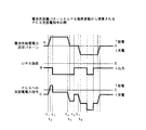
図3は、電池充放電パターンとインバータ負荷変動から演算されるコンバータ充放電指令の波形例を示したものである。横軸は時間を示し、例えば、1日24時間中で昼間は放電、夜間は充電といった電池充放電電力に設定した設定パターンがAであるとき、線Bで示すようなインバータ負荷があったとすると、コンバータ充放電指令演算部6より線Cのような指令値をコンバータCVに出力するよう制御される。
FIG. 3 shows a waveform example of the converter charge / discharge command calculated from the battery charge / discharge pattern and the inverter load fluctuation. The horizontal axis indicates time. For example, when the setting pattern set for battery charge / discharge power such as discharge during the daytime and charge during the nighttime is A, the inverter load as shown by the line B is assumed. The converter charge / discharge
本発明においては、線Aで示す設定パターンが0のとき、すなわち、時刻t5〜t7間において線Cで示す指令値を出力するが、その際、電力貯蔵用2次電池に流れる電流が零若しくは僅かに充放電するよう制御される。 In the present invention, when the setting pattern indicated by the line A is 0, that is, the command value indicated by the line C is output between times t 5 and t 7 , the current flowing through the secondary battery for power storage is It is controlled to charge / discharge zero or slightly.
以下具体的に説明する。
図4は変換効率演算部1の構成図を示したもので、11は乗算器よりなる電池電力演算器で、検出されたコンバータの直流電圧V1と電力貯蔵用2次電池電流I2との掛け算を行なうことによって電池電力を求める。12は乗算器よりなるインバータ電力演算器で、直流電圧V1とインバータIVの直流電流I1との掛け算を行なうことによってインバータ電力(UPS電力)を求める。電池電力演算器11で求めた電池電力値と、インバータ電力演算器12にて求められたインバータ電力値はそれぞれ減算器13に出力されて、この減算器13において「電池電力−インバータ電力」の減算が行なわれ、その結果がコンバータ直流電力(PCS直流電力)として出力される。
This will be specifically described below.
FIG. 4 shows a configuration diagram of the conversion
14は除算器よりなる直交変換効率演算器で、この演算器14は検出された交流側の電圧,電流v1,i1により求められたコンバータ交流有効電力(PCS交流有効電力)とコンバータ直流電力とを用いて「PCS交流有効電力÷PCS直流電力」の除算を行なって直交変換効率信号を算出する。15は除算器よりなる交直変換効率演算器で、この演算器15では、「PCS直流電力÷PCS交流有効電力」の除算演算を行って交直変換効率信号を算出する。
このように変換効率演算部1で直交或いは交直変換効率信号に換算して受電点の電力を常時監視し、その信号をコンバータ充放電指令演算部6に出力することにより、この演算部6は受電点に悪い影響を与えないようコンバータCVの制御信号として使用する。
In this way, the conversion
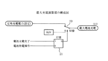
図5は最大充電演算部2の構成図を示したものである。
最大充電演算部2は、設定された定格充電電力と0kWの何れかが電池の最大充電値とされる。そのために切換器20が設けられ、切換信号としては、電池充電完了信号でセットされ、電池放電操作時にリセットされる記憶部21の出力信号等が用いられる。最大充電演算部2の最大充電値が0kWに選択されることは、図示省略の電池制御部から発せられる電池充電完了信号が出力された場合に、電力貯蔵用2次電池にそれ以上の充電電流が流れないよう制限するためのものである。
FIG. 5 shows a configuration diagram of the maximum
In the maximum
図6は最大放電演算部3の構成図を示したものである。
最大放電演算部3は、設定された定格放電電力と0kWの何れかが電池の最大放電値とされる。そのために切換器30が設けられ、切換信号としては、電池放電完了信号でセットされ、電池充電操作時にリセットされる記憶部31の出力信号等が用いられる。最大放電値が0kWに切り換わることにより、電力貯蔵用2次電池が放電完了状態となってそれ以上放電できないよう制限される。
FIG. 6 shows a configuration diagram of the maximum
The maximum
図7は誤差分演算部4の構成図で、41及び42は第1及び第2の減算器で、第1減算器41は、後述するコンバータ充放電指令演算部6において求められたコンバータ直流電力目標値と変換効率演算部1において求めたインバータ電力値とをそれぞれ導入して両者の減算を行なう。第2減算器42では、その結果値と電池電力値との減算を実行して乗算器43に出力し、乗算器43において任意の定数,例えば0.5との乗算が行われ加算器44に出力される。加算器44では、前回求められた誤差分との和算が実行されて範囲設定部45に出力される。なお、定数としては、0<x<1.0の範囲ならば有効で、誤差補正の効き具合に応じて適宜設定される。
Figure 7 is a block diagram of an
範囲設定部45は、誤差上限及び下限を設定するためのもので、その範囲はコンバータの電力制御精度や計測精度、及び電池特性に依存するが、コンバータ定格(PCS定格)の±10%程度以下に設定され、ここでは、コンバータの定格に対して±2%の範囲として、加算器44から入力された信号がこの範囲を逸脱しないよう制限して次回の誤差信号として加算器44に出力すると共に、コンバータ充放電指令演算部6に出力される。
なお、この誤差分演算部4は、コンバータCVの電力制御精度がよければ必ずしも必要としないものである。
The
The
図8は指令値演算部5の構成図を示したものである。
同図において、51は比較器で、現在の要求電池電力値(電池電力値)と0kWとがこの比較器51において比較される。この比較は、電池電力値が正であるか負であるかの極性比較であり、要求電池電力値の極性が負のとき、すなわち、充電モードとなったときに出力を発して切換器54を最小選択部52から最大選択部53側に切換える。
最小選択部52は、電池電力値と図6の最大電池放電信号とを入力してその小さい方を選択出力する。また、最大選択部53は、電池電力値と図5の最大電池充電信号とを入力し、その大きい方を選択出力する。すなわち、充電モードを負極性符号で表現しているため、充電電力の最大値の制限としては数値として最も大きな値を使用する。
FIG. 8 shows a configuration diagram of the command
In the figure,
The
切換器54で切換えられた何れか一方の出力が次回の指令電池電力値の上限値となってコンバータ充放電指令演算部6に出力される。55は微小の充放電補正値演算部で、この演算部は比較器56と切換器57,58及び記憶部59とを有している。
切換器58はコンバータ定格の例えば+2%を微小な放電信号とし、−2%を微小な充電信号として切換を行い、この切換は記憶部59の出力信号によって切り換わる。したがって、比較器56の比較信号A(次回指令電池電力)は、次回指令電池電力値Aと基準電力0kWとの比較によって両者が等しいか、或いは略等しい状態となった−2%<A<+2%のときに切換器57を切換えて微小充放電補正分を出力する。
記憶部59は、電池放電完了信号によってセットされ、電池充電操作信号によってリセットされる。すなわち、電池放電完了信号が記憶部59に入力された時には、記憶部59はそれ以上の放電を防止するために切換器58を−2%側に切換え、微小充放電補正分を微小な充電電力補正分として出力する。また、記憶部59に電池充電操作信号が入力された時には、切換器58は+2%に切換えられて
微小充放電補正分を微小な放電電力補正分として出力する。
One of the outputs switched by the
The switching
The
図9はコンバータ充放電指令演算部6の構成図を示したものである。
61は減算器で、指令電池電力演算部5にて求められた次回の指令電池電力値から図4で算出された現在のインバータ電力値を減算し、その出力を加算器62に出力する。加算器62では入力されたこの減算信号と微小充放電補正信号とを加算し、更に、この加算値は加算器63に送られて誤差分と加算され、コンバータ(PCS)直流電力目標値が生成される。なお、誤差分演算部4が省略されたときには加算器63は省略され、加算器62の出力がコンバータ直流電力目標値となる。
FIG. 9 shows a configuration diagram of the converter charge / discharge
64は切換器で、乗算器66若しくは除算器67の何れかに切り換えてコンバータ直流電力目標値を出力する。65は比較器で、この比較器はコンバータ直流電力目標値と0kWとの比較を行い、目標値が0kW以下、すなわち負(充電時)のときに出力を発して切換器64及び切換器68を図の状態より除算器67側にそれぞれ切り換える。
乗算器66はコンバータ直流電力目標値とコンバータCVにおける直交変換時の効率算出信号との掛け算が行われ、また、除算器67ではコンバータ直流電力目標値をコンバータCVにおける交直変換時の効率算出信号にて除算する演算が行われ、切換器68によって何れかに切り換えられてコンバータ(PCS)充放電指令としてコンバータ制御信号に使用される。
したがって、電力貯蔵用2次電池と直列に接続するスイッチ回路を設けなくとも、コンバータの制御信号には、電力貯蔵用2次電池へ流れる電流を0或いは僅かな放電状態(放電完了状態では僅かな充電)に維持することができ、2次電池の過充電が防止できる。
The
Therefore, even if a switch circuit connected in series with the secondary battery for power storage is not provided, the control signal of the converter is such that the current flowing to the secondary battery for power storage is 0 or a slight discharge state (a little in the discharge complete state). Charge) and overcharge of the secondary battery can be prevented.
1…変換効率演算部
2…最大充電演算部
3…最大放電演算部
4…誤差分演算部
5…指令電池電力演算部
6…コンバータ充放電指令演算部
1 ... Conversion
3. Maximum discharge calculation section
4 ... Error calculation unit
5 ... Command battery
Claims (8)
前記電力貯蔵用2次電池の充電完了後と放電完了後は、それぞれコンバータを通過する電力とインバータの負荷電力を、コンバータ通過電力≦インバータ負荷電力となるよう制御し、電力貯蔵用2次電池に流れる充電電流、及び放電電流を、コンバータの電力制御性能に応じた誤差分状態に維持することを特徴とした電力貯蔵機能付き無停電電源装置の制御方法。 In an uninterruptible power supply that connects a secondary battery for power storage to a DC circuit between the converter and the inverter and charges and discharges the secondary battery for power storage while controlling the converter.
After completion of charging and discharging of the secondary battery for power storage, the power passing through the converter and the load power of the inverter are controlled so that the converter passing power ≦ the inverter load power. A control method for an uninterruptible power supply with a power storage function, wherein a flowing charging current and a discharging current are maintained in an error state corresponding to a power control performance of a converter.
検出されたコンバータCVの直流電圧と電力貯蔵用2次電池電流との積で求めた電力貯蔵用2次電池の電力値と、前記コンバータの直流電圧とインバータ直流回路を流れる検出電流の積からインバータIVの直流電力値を求め、これら求めた各電力値からコンバータCVにおける交直及び直交変換効率を算出する変換効率演算部1と、
前記電力貯蔵用2次電池の充電完了信号により、前記電力貯蔵用2次電池の定格充電電力設定値と予め設定される充電完了時制限電力との何れが一方に切替えて電力貯蔵用2次電池の最大充電電力とする最大充電演算部2と、
前記電力貯蔵用2次電池の放電完了信号により、前記電力貯蔵用2次電池の定格放電電力設定値と予め設定される放電完了時制限電力との切換によって何れか一方を電力貯蔵用2次電池の最大放電電力とする最大放電演算部3と、
前記電力貯蔵用2次電池の現在における電池電力と、前記最大充電電力値、及び最大放電電力値の比較で充放電方向を選択し、この比較信号に基づいて前記最大充電電力値と最大放電電力値との何れかを次回の指令電池電力値の上限値とすると共に、次回の指令電池電力値が基準電力と同等以外のときには微小充放電補正信号を0として出力し、次回の指令電池電力値が基準電力と同等となったときに設定された任意の微小充放電補正信号を出力する指令電池電力演算部5と、
この演算部の出力信号と前記インバータIVの電力値からコンバータCVの直流電力値の目標値を算出し、この目標値が放電方向の場合に前記直交変換効率信号を乗算して直交変換時におけるコンバータ放電指令とし、前記目標値が充電方向の場合には前記交直変換効率信号にて除算することによって交直変換時のコンバータ充電指令とするコンバータ充放電指令演算部6
を備えたことを特徴とした電力貯蔵機能付き無停電電源装置の制御装置。 In an uninterruptible power supply that connects a secondary battery for power storage to a DC circuit between the converter CV and the inverter IV and charges and discharges the secondary battery for power storage while controlling the converter CV.
The power value of the secondary battery for power storage obtained by the product of the detected DC voltage of the converter CV and the secondary battery current for power storage, and the product of the DC voltage of the converter and the detected current flowing through the inverter DC circuit A conversion efficiency calculation unit 1 that calculates the DC power value of IV and calculates the AC / DC and orthogonal conversion efficiency in the converter CV from each of the determined power values;
Depending on the charging completion signal of the secondary battery for power storage, either the rated charging power setting value of the secondary battery for power storage or the preset limited power at the time of charging completion is switched to one, and the secondary battery for power storage A maximum charge calculation unit 2 for the maximum charge power of
Depending on the discharge completion signal of the secondary battery for power storage, either one of the secondary battery for power storage is switched by switching between a rated discharge power setting value of the secondary battery for power storage and a preset limit power at the time of discharge completion. A maximum discharge calculation unit 3 for the maximum discharge power of
A charge / discharge direction is selected by comparing the current battery power of the secondary battery for power storage, the maximum charge power value, and the maximum discharge power value, and the maximum charge power value and the maximum discharge power are selected based on the comparison signal. Is set as the upper limit value of the next command battery power value, and when the next command battery power value is not equal to the reference power, a minute charge / discharge correction signal is output as 0, and the next command battery power value Command battery power calculation unit 5 for outputting an arbitrary minute charge / discharge correction signal set when is equal to the reference power,
The target value of the DC power value of the converter CV is calculated from the output signal of the arithmetic unit and the power value of the inverter IV, and when the target value is in the discharge direction, the orthogonal conversion efficiency signal is multiplied to convert the converter at the time of orthogonal conversion A converter charge / discharge command calculation unit 6 that generates a discharge command and, when the target value is in the charging direction, divides by the AC / DC conversion efficiency signal to obtain a converter charge command at the time of AC / DC conversion.
A control device for an uninterruptible power supply with a power storage function.
Priority Applications (1)
| Application Number | Priority Date | Filing Date | Title |
|---|---|---|---|
| JP2003353232A JP4741179B2 (en) | 2003-10-14 | 2003-10-14 | Control method and apparatus for uninterruptible power supply with power storage function |
Applications Claiming Priority (1)
| Application Number | Priority Date | Filing Date | Title |
|---|---|---|---|
| JP2003353232A JP4741179B2 (en) | 2003-10-14 | 2003-10-14 | Control method and apparatus for uninterruptible power supply with power storage function |
Publications (3)
| Publication Number | Publication Date |
|---|---|
| JP2005124249A JP2005124249A (en) | 2005-05-12 |
| JP2005124249A5 JP2005124249A5 (en) | 2006-07-06 |
| JP4741179B2 true JP4741179B2 (en) | 2011-08-03 |
Family
ID=34611569
Family Applications (1)
| Application Number | Title | Priority Date | Filing Date |
|---|---|---|---|
| JP2003353232A Expired - Fee Related JP4741179B2 (en) | 2003-10-14 | 2003-10-14 | Control method and apparatus for uninterruptible power supply with power storage function |
Country Status (1)
| Country | Link |
|---|---|
| JP (1) | JP4741179B2 (en) |
Families Citing this family (3)
| Publication number | Priority date | Publication date | Assignee | Title |
|---|---|---|---|---|
| JP6071539B2 (en) * | 2012-12-27 | 2017-02-01 | 三菱重工業株式会社 | Power storage system and control method |
| CN109952690A (en) * | 2016-11-11 | 2019-06-28 | 东芝三菱电机产业系统株式会社 | Uninterrupted power supply |
| CN111750556B (en) * | 2020-06-22 | 2022-03-25 | 台州中穗科技有限公司 | Grain cooling machine |
Family Cites Families (10)
| Publication number | Priority date | Publication date | Assignee | Title |
|---|---|---|---|---|
| JPH11355974A (en) * | 1998-06-04 | 1999-12-24 | Matsushita Electric Ind Co Ltd | Control of charging for storage battery and power supply equipment using the method |
| JP3495606B2 (en) * | 1998-08-25 | 2004-02-09 | 日本電信電話株式会社 | Power storage system using sodium sulfur battery and charge / discharge control method thereof |
| JP2000278866A (en) * | 1999-03-22 | 2000-10-06 | Masaaki Iwata | Power storage uninterruptive power supply |
| JP3505124B2 (en) * | 2000-03-28 | 2004-03-08 | 東京電力株式会社 | Emergency power supply system and system for automatically detecting the presence or absence of failure of a single cell in a battery used in the system |
| JP2002281693A (en) * | 2001-03-21 | 2002-09-27 | Shin Kobe Electric Mach Co Ltd | Power storage system |
| JP2003125543A (en) * | 2001-10-15 | 2003-04-25 | Ngk Insulators Ltd | Power storage and compensation system based on high- temperature secondary battery |
| JP2003134691A (en) * | 2001-10-26 | 2003-05-09 | Matsushita Electric Ind Co Ltd | Power supply system |
| JP2003164074A (en) * | 2001-11-27 | 2003-06-06 | Shin Kobe Electric Mach Co Ltd | Control method for charger of uninterruptible power supply system |
| JP3795414B2 (en) * | 2002-03-05 | 2006-07-12 | 株式会社エヌ・ティ・ティ ファシリティーズ | AC power supply system |
| JP4218867B2 (en) * | 2002-10-30 | 2009-02-04 | Tdkラムダ株式会社 | Uninterruptible power system |
-
2003
- 2003-10-14 JP JP2003353232A patent/JP4741179B2/en not_active Expired - Fee Related
Also Published As
| Publication number | Publication date |
|---|---|
| JP2005124249A (en) | 2005-05-12 |
Similar Documents
| Publication | Publication Date | Title |
|---|---|---|
| JP6238107B2 (en) | Storage battery management system | |
| US7522435B2 (en) | Power supply converter/s with controller/s responsive to voltage, current, and power | |
| US20120319664A1 (en) | Dc power supply system | |
| JP6725647B2 (en) | Uninterruptible power system | |
| CN112840520A (en) | System, control device, and control method for system | |
| JP2008099527A (en) | Storage battery system in non-utility generation equipment connected to electric power system and driving method therefor | |
| JP2012100504A (en) | Power supply system | |
| EP2592713A2 (en) | Battery power supply device and power controlling method for same | |
| JP2008131736A (en) | Distributed power system and step-up/step-down chopper device | |
| WO2020170550A1 (en) | Power conversion system | |
| JPWO2012050195A1 (en) | Power supply system | |
| JP2016201966A (en) | Power conversion device | |
| JP2022179781A (en) | power conversion system | |
| JP6426014B2 (en) | Bidirectional inverter and storage system using the same | |
| JP2008125218A (en) | Distributed power supply control system | |
| JP6877640B2 (en) | Power converter and power conversion system | |
| EP0607011B1 (en) | Control device for system interconnection inverter | |
| JP4741179B2 (en) | Control method and apparatus for uninterruptible power supply with power storage function | |
| EP2352214A1 (en) | Output power control apparatus | |
| JP5721498B2 (en) | Demand control device | |
| JP2003116225A (en) | Distributed power supply system | |
| WO2018138710A1 (en) | Dc power supply system | |
| JP2000323365A (en) | Dc supplying device | |
| KR101627620B1 (en) | Uninterruptible Power Supply | |
| Joshi et al. | Modified ultracapacitor voltage control loop for battery/UC HESS |
Legal Events
| Date | Code | Title | Description |
|---|---|---|---|
| A521 | Written amendment |
Free format text: JAPANESE INTERMEDIATE CODE: A523 Effective date: 20060524 |
|
| A621 | Written request for application examination |
Free format text: JAPANESE INTERMEDIATE CODE: A621 Effective date: 20060524 |
|
| A977 | Report on retrieval |
Free format text: JAPANESE INTERMEDIATE CODE: A971007 Effective date: 20080523 |
|
| A131 | Notification of reasons for refusal |
Free format text: JAPANESE INTERMEDIATE CODE: A131 Effective date: 20081007 |
|
| A521 | Written amendment |
Free format text: JAPANESE INTERMEDIATE CODE: A523 Effective date: 20081204 |
|
| A131 | Notification of reasons for refusal |
Free format text: JAPANESE INTERMEDIATE CODE: A131 Effective date: 20091215 |
|
| A521 | Written amendment |
Free format text: JAPANESE INTERMEDIATE CODE: A523 Effective date: 20100209 |
|
| A131 | Notification of reasons for refusal |
Free format text: JAPANESE INTERMEDIATE CODE: A131 Effective date: 20110322 |
|
| A521 | Written amendment |
Free format text: JAPANESE INTERMEDIATE CODE: A523 Effective date: 20110411 |
|
| TRDD | Decision of grant or rejection written | ||
| A01 | Written decision to grant a patent or to grant a registration (utility model) |
Free format text: JAPANESE INTERMEDIATE CODE: A01 Effective date: 20110426 |
|
| A01 | Written decision to grant a patent or to grant a registration (utility model) |
Free format text: JAPANESE INTERMEDIATE CODE: A01 |
|
| A61 | First payment of annual fees (during grant procedure) |
Free format text: JAPANESE INTERMEDIATE CODE: A61 Effective date: 20110506 |
|
| R150 | Certificate of patent or registration of utility model |
Free format text: JAPANESE INTERMEDIATE CODE: R150 |
|
| FPAY | Renewal fee payment (event date is renewal date of database) |
Free format text: PAYMENT UNTIL: 20140513 Year of fee payment: 3 |
|
| S533 | Written request for registration of change of name |
Free format text: JAPANESE INTERMEDIATE CODE: R313533 |
|
| R350 | Written notification of registration of transfer |
Free format text: JAPANESE INTERMEDIATE CODE: R350 |
|
| LAPS | Cancellation because of no payment of annual fees |