EP0581322A2 - Method of damping harmonics and device for connecting to a network - Google Patents
Method of damping harmonics and device for connecting to a network Download PDFInfo
- Publication number
- EP0581322A2 EP0581322A2 EP93112312A EP93112312A EP0581322A2 EP 0581322 A2 EP0581322 A2 EP 0581322A2 EP 93112312 A EP93112312 A EP 93112312A EP 93112312 A EP93112312 A EP 93112312A EP 0581322 A2 EP0581322 A2 EP 0581322A2
- Authority
- EP
- European Patent Office
- Prior art keywords
- voltage
- partial
- converter
- network
- transformers
- Prior art date
- Legal status (The legal status is an assumption and is not a legal conclusion. Google has not performed a legal analysis and makes no representation as to the accuracy of the status listed.)
- Withdrawn
Links
Images


Classifications
-
- H—ELECTRICITY
- H02—GENERATION; CONVERSION OR DISTRIBUTION OF ELECTRIC POWER
- H02M—APPARATUS FOR CONVERSION BETWEEN AC AND AC, BETWEEN AC AND DC, OR BETWEEN DC AND DC, AND FOR USE WITH MAINS OR SIMILAR POWER SUPPLY SYSTEMS; CONVERSION OF DC OR AC INPUT POWER INTO SURGE OUTPUT POWER; CONTROL OR REGULATION THEREOF
- H02M7/00—Conversion of ac power input into dc power output; Conversion of dc power input into ac power output
- H02M7/42—Conversion of dc power input into ac power output without possibility of reversal
- H02M7/44—Conversion of dc power input into ac power output without possibility of reversal by static converters
- H02M7/48—Conversion of dc power input into ac power output without possibility of reversal by static converters using discharge tubes with control electrode or semiconductor devices with control electrode
- H02M7/483—Converters with outputs that each can have more than two voltages levels
- H02M7/49—Combination of the output voltage waveforms of a plurality of converters
-
- H—ELECTRICITY
- H02—GENERATION; CONVERSION OR DISTRIBUTION OF ELECTRIC POWER
- H02J—CIRCUIT ARRANGEMENTS OR SYSTEMS FOR SUPPLYING OR DISTRIBUTING ELECTRIC POWER; SYSTEMS FOR STORING ELECTRIC ENERGY
- H02J3/00—Circuit arrangements for ac mains or ac distribution networks
- H02J3/34—Arrangements for transfer of electric power between networks of substantially different frequency
-
- H—ELECTRICITY
- H02—GENERATION; CONVERSION OR DISTRIBUTION OF ELECTRIC POWER
- H02M—APPARATUS FOR CONVERSION BETWEEN AC AND AC, BETWEEN AC AND DC, OR BETWEEN DC AND DC, AND FOR USE WITH MAINS OR SIMILAR POWER SUPPLY SYSTEMS; CONVERSION OF DC OR AC INPUT POWER INTO SURGE OUTPUT POWER; CONTROL OR REGULATION THEREOF
- H02M7/00—Conversion of ac power input into dc power output; Conversion of dc power input into ac power output
- H02M7/42—Conversion of dc power input into ac power output without possibility of reversal
- H02M7/44—Conversion of dc power input into ac power output without possibility of reversal by static converters
- H02M7/48—Conversion of dc power input into ac power output without possibility of reversal by static converters using discharge tubes with control electrode or semiconductor devices with control electrode
- H02M7/483—Converters with outputs that each can have more than two voltages levels
- H02M7/487—Neutral point clamped inverters
Definitions
- the invention is based on 2 methods for damping at least one voltage harmonic or one harmonic at the mains frequency in an AC voltage network according to the preamble of claims 1 and 6, as well as a static compensator or a network coupling for carrying out the method according to claim 1.
- the invention relates to a prior art, as is known from DE-A1-1 438 651.
- several partial transformers connected in series are connected to a 3-phase AC voltage network, one partial transformer having a transformation ratio from the transformer winding on the line side to the converter winding on the converter side, which is equal to ⁇ 3 times the voltage translation of at least one other partial transformer.
- the step heights in the total voltage are approximated to a sine curve, the total area of step areas lying below the sine curve being at least approximately equal to the total area of step areas above the sine curve.
- EP-B1-0 254 911 describes a converter with a converter circuit on the rail network side, which is operatively connected to a rail network via a voltage summing transformer with 13 magnetically decoupled partial transformers.
- the line-side windings of the partial transformers are connected in series, while the windings on the converter side are each operatively connected to a converter.
- Each converter which consists of a single-phase bridge circuit with a GTO thyristor and an anti-parallel diode per bridge branch, has a thyristor AC switch in parallel with its AC connection.
- Such inverters with an impressed voltage generate an AC voltage by switching the DC voltage in sections at the AC-side load or at the AC-side mains connection.
- the voltage generated by the converters contains disturbing voltage harmonics. Due to the large number of partial converters connected in series on the AC side, which supply offset square-wave voltages, a sinusoidal voltage is approximated.
- the disadvantage here is the division into many small units, which in particular causes high costs for the converter transformers, means increased space requirements and reduces the reliability of the overall system.
- DE-A1-4 037 531 a method for controlling rectifiers in which 2 rectifiers or 4-quadrant actuators, which are connected on the rail network side to separate secondary windings of a network transformer, are clocked out of phase to reduce harmonics that occur during clocking.
- a 3-point circuit is used for the DC link of the converter.
- the invention solves the problem of 2 methods for damping at least one harmonic to the mains frequency in an AC network and a static compensator or a network coupling for carrying out the method according to claim 1 of the aforementioned Way to develop in such a way that a harmonic attenuation is possible with simpler means.
- An advantage of the invention is that the cost and space requirements are reduced. At the same time, a higher reliability of the network coupling is achieved.
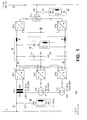
- Fig. 1 with (1) is a single-phase 16 2/3 Hz rail network or 1-phase network or AC network with an AC voltage of 110 kV and with 7 a 3-phase 50 Hz state network or 3-phase network with an AC voltage of 110 kV designated.
- the rail network (1) is connected via a switch (S1) to a voltage summing transformer which consists of 3 sub-transformers (Tr1 - Tr3) which have transformer cores that are not magnetically coupled to one another.
- Each partial transformer (Tr1 - Tr3) has a transformer winding (W1) on the mains side and a transformer winding (W2) on the converter side.
- the transformer windings on the mains side (W1) are connected in series and grounded at the ends.
- Each converter winding on the converter side (W2) is connected via AC voltage connections to a separate 4-quadrant converter or converter or partial converter (ST1 - ST3), the circuit of which is shown in FIG. 2.
- Each of the 3 sub-transformers (Tr1 - Tr3) has a short circuit voltage of 20%.
- the partial transformers (TR1) and (Tr3) are designed for a power of 14.5 MVA and for a voltage drop of 31.8 kV, while the partial transformer (TR2) is designed for a power of 25 MVA and a voltage drop of 55 kV.
- the partial converters (ST1 - ST3) and the associated partial transformers (Tr1 - Tr3) are operated with different phase shifts or phase shifts of the converter voltages, namely with a phase shift of + 30 ° el. or 0 ° el. or -30 ° el.
- the 3 partial converters (ST1 - ST3) are designed in a 3-point circuit and connected in parallel on the DC voltage side, with a positive pole (8), a negative pole (9) and a zero pole (PO).
- the partial converters (ST1 - ST3) are connected via a DC link (3) with 2 DC converters connected in series on the DC side (ST4, ST5) connected, which are connected to the country network (7) on the AC voltage side via a winding transformer or network transformer (TR4) and a switch (S4).
- electrical energy can be transmitted from the state network (7) to the rail network (1) via the DC link (3).
- energy transfer in the opposite direction is also possible.
- the DC voltage intermediate circuit (3) has an intermediate circuit choke (5) in each DC voltage line (8, 9), furthermore 2 DC link capacitors (C1, C2) connected in series, the common connecting line of which is connected to the zero pole (P0) of the partial converters (ST1 - ST3) is, and a high-pass filter (4), the second harmonic of the rail network (1), d. H. to 33 1/3 Hz, and is designed for a reactive power of 15 MVar. If only one DC link choke (5) is provided, the zero pole (P0) must not be earthed.
- high-pass filters (2) and (6) are connected to the supply lines to the respective network transformers via switches (S2) and (S3), which are matched to the 12th harmonic of the respective power network (1) or (7) and for reactive power of 10 MVar and 15 MVar are designed; they dampen the 11th and 13th harmonics.
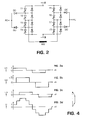
- the 4-quadrant actuator shown has 4 bridge branches, each with 2 GTO thyristors (T1, T2) or (T3, T4) or (T5, T6) or (T7, T8) connected in series, with antiparallel to each GTO thyristor a diode is connected.
- the connecting lines of the GTO thyristors (T2) and (T3) as well as the GTO thyristors (T6) and (T7) form the AC voltage inputs of the 4-quadrant actuator, which are connected with the transformer winding (W2) on the converter side.
- the connecting lines of the GTO thyristors (T1) and (T2) and those of the GTO thyristors (T5) and (T6) are each connected to the cathode of a zero-point diode (D0), which is connected to the zero pole (P0) on the anode side.
- the connecting lines of the GTO thyristors (T3) and (T4) and those of the GTO thyristors (T7) and (T8) are each connected to the anode of a zero-point diode (D0), which is connected on the cathode side to the zero pole (P0) .
- the transformation ratio of the partial transformers (Tr1 - Tr3) is important for achieving the desired harmonic reduction.
- the partial transformer (Tr2) delivers a ⁇ 3 times the line-side voltage in comparison to the line-side voltages of the partial transformers (Tr1, Tr3).
- the partial converters (ST1 - ST3) can be in 3-point operation according to FIGS. 1 and 2 or in 2-point operation, cf. 11, are operated, the thyristors (T1, T4, T5, T8) with associated antiparallel diodes and the zero-point diodes (D0) being omitted in the circuit of FIG. 2.
- the voltage levels are each 30 ° el. mutually shifted in phase, the amplitude of the partial voltage (U2) being ⁇ 3 times that of the other two partial voltages (U1, U3).
- FIG. 4 shows the addition of the voltage pointers assigned to the total voltage (U) according to FIG. 3d.
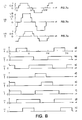
- 5a-5d show firing pulse patterns for the GTO thyristors (T2, T3, T6, T7) for generating the voltage forms of FIG. 3a by the partial converter (ST1).
- 5a and 5d show the on-times of the thyristors (T2) and (T3), while FIGS. 5b and 5c show on-times of the thyristors (T6) and (T7) which are phase-shifted by 120 °.
- the thyristors (T2) and (T3) or (T6) and (T7) are always fired alternately.
- This ignition pulse pattern results in 120 ° rectangular blocks of the converter alternating voltage which are free from harmonics of the atomic number 3, 9, 15 etc., i. H. free of harmonics that are divisible by 3.
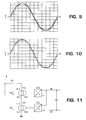
- the partial voltages (U1 - U3) of the partial transformers (Tr1 - Tr3) are around 30 ° el. offset from each other so that there is just 12 pulses with the transformer ratio mentioned, cf. 3a-3c and Fig. 10 with a computer simulation in which a Fourier analysis provides the lowest amplitudes for the 11th and 13th harmonics.
- FIGS. 6a-6c show voltage signal diagrams of a first converter system, corresponding to FIG. 1, and FIGS. 6d-6f show those of a second identical converter system, which is 15 ° el. From the first converter system. is out of phase, both without zero-point diodes (D0). This doubling results in a quasi 24-pulse reaction, cf. the computer simulation in FIG. 9.
- FIGS. 6a - 6f show voltage signal diagrams of the 3 partial transformers (Tr1 -Tr3) in a 3-point operation of the 3 connected partial converters (ST1-ST3) according to the Fig. 1 and 2.
- 3-point operation the potentials +, 0 and - of the DC voltage side are switched through alternately.
- partial converters (ST1 - ST3) according to FIG. 1 it is possible with partial converters (ST1 - ST3) according to FIG. 1 to achieve the same 24-pulse rate as with two subsystems in the two-point system according to FIGS. 6a - 6f.
- FIG 11 shows a converter circuit for two-point operation with only two partial converters (STa) and (STb), which are connected on the AC side to partial transformers (Tra) and (Trb), which generate partial voltages (Ua, Ub) on their transformer windings (W1) on the mains side.
- the partial converters (STa) and (STb) are connected in parallel.
- the transformation ratio of the line-side transformer winding (W1) to the converter-side transformer winding (W2) is 3: 1 for the partial transformer (Tra) and 1: 1 for the partial transformer (Trb).
- FIGS. 12a and 12b show voltage signal diagrams of the partial voltages (Ua) and (Ub) that can be created with a converter circuit according to FIG. 11.
- 12c shows the associated sum signal diagram from which the 6-pulse rate achieved can be seen.
- FIGS. 13a and 13b show voltage signal diagrams of the partial voltages (U1) and (U3) which can be created with a circuit according to FIG. 1 if the partial transformer (Tr2) with connected partial converter (ST2) is omitted. 13c shows the associated sum signal diagram from which the 6-pulse rate achieved can be seen.
- the partial converter (ST3) is operated with 3 potential levels, which requires more effort than a converter with 2-point operation.
- FIG. 14 shows a voltage signal diagram with an optimal stair curve of 5 voltage levels.
- the step curve generated by means of a network coupling (not shown) with 5 partial converters and 5 partial transformers should run in such a way that it approximates a sine curve (10) as well as possible.
- ( ⁇ i ) the ignition angle or the phase shift of an i. Level or an i. Partial converter and with (S i ) an i. Step height or line-side transformer partial voltage designated.
- a hatched step area below the sine curve (10) is denoted by (Fu) and a step area above the sinus curve (10), also hatched, is denoted by (Fo).
- the steps must be selected so that the total area of the step areas (Fu) below the sine curve (10) is equal to that Total area of the step areas (Fo) above the sine curve (10).
- the step height (S i ) should be greater than in areas with a smaller slope; that is, S i should be selected proportional to cos ⁇ i .
- the invention is also suitable for static compensators for compensating reactive power z. B. in the circuit of FIG. 11th
Abstract
Description
Bei der Erfindung wird ausgegangen von 2 Verfahren zur Dämpfung mindestens einer Spannungsoberschwingung bzw. einer Oberschwingung zur Netzfrequenz in einem Wechselspannungsnetz nach dem Oberbegriff der Patentansprüche 1 und 6 sowie von einem statischen Kompensator bzw. von einer Netzkupplung zur Durchführung des Verfahrens nach Anspruch 1.The invention is based on 2 methods for damping at least one voltage harmonic or one harmonic at the mains frequency in an AC voltage network according to the preamble of
Mit dem Oberbegriff der Patentansprüche 1, 6 und 7 nimmt die Erfindung auf einen Stand der Technik Bezug, wie er aus der DE-A1-1 438 651 bekannt ist. Dort sind mehrere in Reihe geschaltete Teiltransformatoren an ein 3phasiges Wechselspannungsnetz angeschlossen, wobei ein Teiltransformator ein Übersetzungsverhältnis von netzseitiger Transformatorwicklung zu stromrichterseitiger Transformatorwicklung aufweist, die gleich dem √3fachen der Spannungsübersetzung mindestens eines anderen Teiltransformators ist. Die Stufenhöhen in der Summenspannung sind einer Sinuskurve angenähert, wobei die Summenfläche von unterhalb der Sinuskurve liegenden Stufenflächen wenigstens annähernd gleich der Summenfläche von Stufenflächen oberhalb der Sinuskurve ist.With the preamble of
In der EP-B1-0 254 911 ist ein Umrichter mit einer bahnnetzseitigen Stromrichterschaltung beschrieben, welche über einen Spannungssummiertransformator mit 13 magnetisch entkoppelten Teiltransformatoren mit einem Bahnnetz in Wirkverbindung steht. Die netzseitigen Wicklungen der Teiltransformatoren sind in Reihe geschaltet, während die stromrichterseitigen Wicklungen jeweils mit einem Stromrichter in Wirkverbindung stehen. Jeder Stromrichter, der aus einer einphasigen Brückenschaltung mit je einem GTO-Thyristor und dazu antiparalleler Diode je Brückenzweig besteht, weist parallel zu seinem Wechselstromanschluss einen Thyristor-Wechseltromschalter auf.EP-B1-0 254 911 describes a converter with a converter circuit on the rail network side, which is operatively connected to a rail network via a voltage summing transformer with 13 magnetically decoupled partial transformers. The line-side windings of the partial transformers are connected in series, while the windings on the converter side are each operatively connected to a converter. Each converter, which consists of a single-phase bridge circuit with a GTO thyristor and an anti-parallel diode per bridge branch, has a thyristor AC switch in parallel with its AC connection.
Derartige Umrichter mit eingeprägter Spannung erzeugen eine Wechselspannung durch abschnittsweises Umschalten der Gleichspannung an der wechselstromseitigen Last bzw. am wechselstromseitigen Netzanschluss. Die von den Stromrichtern erzeugte Spannung enthält störende Spannungsoberschwingungen. Durch die vielen wechselstromseitig in Reihe geschalteten Teilstromrichter, die versetzte Rechteckspannungen liefern, wird insgesamt eine sinusförmige Spannung angenähert. Nachteilig ist dabei die Unterteilung in viele kleine Einheiten, was insbesondere hohe Kosten für die Stromrichtertransformatoren verursacht, erhöhten Platzaufwand bedeutet und die Zuverlässigkeit der Gesamtanlage reduziert.Such inverters with an impressed voltage generate an AC voltage by switching the DC voltage in sections at the AC-side load or at the AC-side mains connection. The voltage generated by the converters contains disturbing voltage harmonics. Due to the large number of partial converters connected in series on the AC side, which supply offset square-wave voltages, a sinusoidal voltage is approximated. The disadvantage here is the division into many small units, which in particular causes high costs for the converter transformers, means increased space requirements and reduces the reliability of the overall system.
Zum einschlägigen Stand der Technik wird zusätzlich auf die DE-A1-4 037 531 verwiesen, aus der ein Verfahren zur Steuerung von Gleichrichtern bekannt ist, bei dem 2 Gleichrichter bzw. 4Quadrantensteller, die bahnnetzseitig an separate Sekundärwicklungen eines Netztransformators angeschlossen sind, phasenverschoben getaktet werden, um beim Takten entstehende Oberschwingungen zu reduzieren. Für den Gleichspannungszwischenkreis des Umrichters wird eine 3Punktschaltung verwendet.With regard to the relevant prior art, reference is also made to DE-A1-4 037 531, from which a method for controlling rectifiers is known in which 2 rectifiers or 4-quadrant actuators, which are connected on the rail network side to separate secondary windings of a network transformer, are clocked out of phase to reduce harmonics that occur during clocking. A 3-point circuit is used for the DC link of the converter.
Die Erfindung, wie sie in den Patentansprüchen 1, 6 und 7 definiert ist, löst die Aufgabe, 2 Verfahren zur Dämpfung mindestens einer Oberschwingung zur Netzfrequenz in einem Wechselspannungsnetz sowie einen statischen Kompensator bzw. eine Netzkupplung zur Durchführung des Verfahrens nach Anspruch 1 der eingangs genannten Art derart weiterzuentwickeln, dass eine Oberschwingungsdämpfung mit einfacheren Mitteln möglich wird.The invention, as defined in
Ein Vorteil der Erfindung besteht darin, dass sich die Kosten und der Platzbedarf vermindern. Gleichzeitig wird eine höhere Zuverlässigkeit der Netzkupplung erreicht.An advantage of the invention is that the cost and space requirements are reduced. At the same time, a higher reliability of the network coupling is achieved.
Die Erfindung wird nachstehend anhand von Ausführungsbeispielen erläutert. Es zeigen:
- Fig. 1
- einen Umrichter, der ein Bahnnetz mit einem Landesnetz kuppelt und bahnnetzseitig eine Netzkupplung mit 3 in Reihe geschalteten Transformatoren aufweist, an welche je ein Stromrichter bzw. Teilstromrichter angeschlossen ist,
- Fig. 2
- eine Prinzipschaltung eines Stromrichters gemäss Fig. 1,
- Fig. 3a - 3c
- Spannungssignaldiagramme 3er bahnnetzseitiger Teiltransformatoren gemäss Fig. 1,
- Fig. 3d
- ein Signaldiagramm der Summe der 3 Signaldiagramme gemäss den Fig. 3a - 3c,
- Fig. 4
- ein Vektorsignaldiagramm der Spannungszeiger der 3 Teiltransformatoren,
- Fig. 5a - 5d
- Zündimpulsmuster einer 2phasigen Brückenschaltung ohne Nullpunktdioden,
- Fig. 6a - 6c
- Spannungssignaldiagramme 3er Teiltransformatoren eines 1. Stromrichtersystems ohne Nullpunktdioden,
- Fig. 6d - 6f
- Spannungssignaldiagramme 3er Teiltransformatoren eines 2. Stromrichtersystems ohne Nullpunktdioden, das gegenüber dem 1. Teilstromrichtersystem um 15°el. phasenverschoben ist,
- Fig. 7a - 7c
- Spannungssignaldiagramme 3er Teiltransformatoren, die mit Teilstromrichtern mit Nullpunktdioden in Verbindung stehen,
- Fig. 8a - 8h
- Zündimpulsmuster einer 2phasigen Stromrichterbrücke mit Nullpunktdioden,
- Fig. 9
- ein durch Computersimulation erzeugtes Spannungssignaldiagramm für einen 1phasigen GTO-Umrichter in 3Punktschaltung mit 5 Spannungsstufen,
- Fig. 10
- ein durch Computersimulation erzeugtes Spannungssignaldiagramm für einen 1phasigen GTO-Umrichter in 2Punktschaltung mit 3 Spannungsstufen,
- Fig. 11
- eine Stromrichterschaltung mit 2 in Reihe geschalteten Transformatoren und 2 Stromrichtern in 2Punktschaltung,
- Fig. 12a und 12b
- Spannungssignaldiagramme 2er Teiltransformatoren, die mit Teilstromrichtern in 2Punktschaltung in Verbindung stehen und unterschiedliche Übersetzungen aufweisen,
- Fig. 13a und 13b
- Spannungssignaldiagramme 2er Teiltransformatoren, die mit Teilstromrichtern in 3Punktschaltung in Verbindung stehen und gleiche Übersetzungen aufweisen,
- Fig. 12c und 13c
- Summensignaldiagramme zu den Spannungssignaldiagrammen von Fig. 12a und 12b bzw. 13a und 13b und
- Fig. 14
- ein Spannungssignaldiagramm mit einer optimalen Treppenkurve von Spannungsstufen.
- Fig. 1
- a converter which couples a rail network to a state network and has a network coupling on the rail network side with 3 transformers connected in series, to each of which a converter or partial converter is connected,
- Fig. 2
- 2 shows a basic circuit of a converter according to FIG. 1,
- 3a-3c
- Voltage signal diagrams of 3 sub-transformers on the railway network side according to FIG. 1,
- Fig. 3d
- 3 shows a signal diagram of the sum of the 3 signal diagrams according to FIGS. 3a-3c,
- Fig. 4
- a vector signal diagram of the voltage vector of the 3 partial transformers,
- Figures 5a - 5d
- Firing pulse pattern of a two-phase bridge circuit without zero-point diodes,
- 6a-6c
- Voltage signal diagrams of 3 sub-transformers of a 1st converter system without zero-point diodes,
- 6d-6f
- Voltage signal diagrams of three partial transformers of a second converter system without zero-point diodes, which is 15 ° el. Compared to the first partial converter system. is out of phase,
- 7a-7c
- Voltage signal diagrams of three sub-transformers, which are connected to partial converters with zero-point diodes,
- Figures 8a-8h
- Ignition pulse pattern of a 2-phase converter bridge with zero-point diodes,
- Fig. 9
- a voltage signal diagram generated by computer simulation for a 1-phase GTO converter in 3-point connection with 5 voltage levels,
- Fig. 10
- a voltage signal diagram generated by computer simulation for a 1-phase GTO converter in 2-point connection with 3 voltage levels,
- Fig. 11
- a converter circuit with 2 transformers connected in series and 2 converters in 2-point connection,
- 12a and 12b
- Voltage signal diagrams of two sub-transformers, which are connected to partial converters in a two-point circuit and have different ratios,
- 13a and 13b
- Voltage signal diagrams of 2-part transformers, which are connected to 3-point circuit converters and have the same translations,
- Figures 12c and 13c
- Sum signal diagrams for the voltage signal diagrams of FIGS. 12a and 12b or 13a and 13b and
- Fig. 14
- a voltage signal diagram with an optimal stair curve of voltage levels.
In Fig. 1 ist mit (1) ein einphasiges 16 2/3-Hz-Bahnnetz bzw. 1Phasennetz bzw. Wechselstromnetz mit einer Wechselspannung von 110 kV und mit 7 ein 3phasiges 50-Hz-Landesnetz bzw. 3Phasennetz mit einer Wechselspannung von 110 kV bezeichnet. Das Bahnnetz (1) ist über einen Schalter (S1) mit einem Spannungssummiertransformator verbunden, der aus 3 Teiltransformatoren (Tr1 - Tr3) besteht, die magnetisch nicht miteinander gekoppelte Transformatorkerne haben. Jeder Teiltransformator (Tr1 - Tr3) besitzt eine netzseitige Transformatorwicklung (W1) und eine stromrichterseitige Transformatorwicklung (W2). Die netzseitigen Transformatorwicklungen (W1) sind in Reihe geschaltet und endseitig geerdet. Jede stromrichterseitige Transformatorwicklung (W2) ist über Wechselspannungsanschlüsse an einen separaten 4Quadrantensteller bzw. Stromrichter bzw. Teilstromrichter (ST1 - ST3) angeschlossen, dessen Schaltung in Fig. 2 dargestellt ist. Jeder der 3 Teiltransformatoren (Tr1 - Tr3) besitzt eine Kurzschlussspannung von 20 %. Die Teiltransformatoren (TR1) und (Tr3) sind für eine Leistung von 14,5 MVA und für einen Spannungsabfall von 31,8 kV ausgelegt, während der Teiltransformator (TR2) für eine Leistung von 25 MVA und einen Spannungsabfall von 55 kV ausgelegt ist. Die Teilstromrichter (ST1 - ST3) und die zugehörigen Teiltransformatoren (Tr1 - Tr3) werden mit unterschiedlichen Phasendrehungen bzw. Phasenverschiebungen der Stromrichterspannungen betrieben, und zwar mit einer Phasendrehung von +30°el. bzw. 0°el. bzw. -30°el.In Fig. 1 with (1) is a single-
Die 3 Teilstromrichter (ST1 - ST3) sind in 3Punktschaltung ausgeführt und gleichspannungsseitig parallelgeschaltet, wobei ein Pluspol mit (8), ein Minuspol mit (9) und ein Nullpol mit (PO) bezeichnet sind. Die Teilstromrichter (ST1 - ST3) sind über einen Gleichspannungszwischenkreis (3) mit 2 gleichspannungsseitig in Reihe geschalteten Stromrichtern (ST4, ST5) verbunden, die wechselspannungsseitig über einen 3Wicklungstransformator bzw. Netztransformator (TR4) und einen Schalter (S4) mit dem Landesnetz (7) in Verbindung stehen. In dieser Schaltung kann elektrische Energie aus dem Landesnetz (7) über den Gleichspannungszwischenkreis (3) in das Bahnnetz (1) übertragen werden. Im Prinzip ist auch eine Energieübertragung in entgegengesetzter Richtung möglich.The 3 partial converters (ST1 - ST3) are designed in a 3-point circuit and connected in parallel on the DC voltage side, with a positive pole (8), a negative pole (9) and a zero pole (PO). The partial converters (ST1 - ST3) are connected via a DC link (3) with 2 DC converters connected in series on the DC side (ST4, ST5) connected, which are connected to the country network (7) on the AC voltage side via a winding transformer or network transformer (TR4) and a switch (S4). In this circuit, electrical energy can be transmitted from the state network (7) to the rail network (1) via the DC link (3). In principle, energy transfer in the opposite direction is also possible.
Der Gleichspannungszwischenkreis (3) weist in jeder Gleichspannungsleitung (8, 9) eine Zwischenkreisdrossel (5) auf, ferner 2 in Reihe geschaltete Zwischenkreiskondensatoren (C1, C2), deren gemeinsame Verbindungsleitung an den Nullpol (P0) der Teilstromrichter (ST1 - ST3) angeschlossen ist, und ein Hochpassfilter (4), das auf die 2. Oberschwingung des Bahnnetzes (1), d. h. auf 33 1/3 Hz, abgestimmt und für eine Blindleistung von 15 MVar ausgelegt ist. Falls nur eine Zwischenkreisdrossel (5) vorgesehen ist, darf der Nullpol (P0) nicht geerdet sein.The DC voltage intermediate circuit (3) has an intermediate circuit choke (5) in each DC voltage line (8, 9), furthermore 2 DC link capacitors (C1, C2) connected in series, the common connecting line of which is connected to the zero pole (P0) of the partial converters (ST1 - ST3) is, and a high-pass filter (4), the second harmonic of the rail network (1), d. H. to 33 1/3 Hz, and is designed for a reactive power of 15 MVar. If only one DC link choke (5) is provided, the zero pole (P0) must not be earthed.
Netzseitig sind über Schalter (S2) und (S3) Hochpassfilter (2) bzw. (6) an die Zuleitungen zu den jeweiligen Netztransformatoren angeschlossen, welche auf die 12. Oberschwingung des jeweiligen Stromnetzes (1) bzw (7) abgestimmt und für eine Blindleistung von 10 MVar bzw. 15 MVar ausgelegt sind; sie dämpfen die 11. und 13. Oberschwingung.On the network side, high-pass filters (2) and (6) are connected to the supply lines to the respective network transformers via switches (S2) and (S3), which are matched to the 12th harmonic of the respective power network (1) or (7) and for reactive power of 10 MVar and 15 MVar are designed; they dampen the 11th and 13th harmonics.
Fig. 2 zeigt den Aufbau eines der gleich ausgeführten 1phasigen Teilstromrichter (ST1 - ST3). Der dargestellte 4Quadrantensteller weist 4 Brückenzweige mit je 2 in Reihe geschalteten GTO-Thyristoren (T1, T2) bzw. (T3, T4) bzw. (T5, T6) bzw. (T7, T8) auf, wobei antiparallel zu jedem GTO-Thyristor ein Diode geschaltet ist. Die Verbindungsleitungen der GTO-Thyristoren (T2) und (T3) sowie der GTO-Thyristoren (T6) und (T7) bilden die Wechselspannungseingänge des 4Quadrantenstellers, die mit der stromrichterseitigen Transformatorwicklung (W2) verbunden sind. Die Verbindungsleitungen der GTO-Thyristoren (T1) und (T2) sowie diejenigen der GTO-Thyristoren (T5) und (T6) sind mit der Kathode je einer Nullpunktdiode (D0) verbunden, welche anodenseitig mit dem Nullpol (P0) in Verbindung steht. Die Verbindungsleitungen der GTO-Thyristoren (T3) und (T4) sowie diejenigen der GTO-Thyristoren (T7) und (T8) sind jeweils mit der Anode je einer Nullpunktdiode (D0) verbunden, welche kathodenseitig mit dem Nullpol (P0) in Verbindung steht.2 shows the structure of one of the identically designed 1-phase partial converters (ST1 - ST3). The 4-quadrant actuator shown has 4 bridge branches, each with 2 GTO thyristors (T1, T2) or (T3, T4) or (T5, T6) or (T7, T8) connected in series, with antiparallel to each GTO thyristor a diode is connected. The connecting lines of the GTO thyristors (T2) and (T3) as well as the GTO thyristors (T6) and (T7) form the AC voltage inputs of the 4-quadrant actuator, which are connected with the transformer winding (W2) on the converter side. The connecting lines of the GTO thyristors (T1) and (T2) and those of the GTO thyristors (T5) and (T6) are each connected to the cathode of a zero-point diode (D0), which is connected to the zero pole (P0) on the anode side. The connecting lines of the GTO thyristors (T3) and (T4) and those of the GTO thyristors (T7) and (T8) are each connected to the anode of a zero-point diode (D0), which is connected on the cathode side to the zero pole (P0) .
Wichtig für das Zustandekommen der gewünschten Oberschwingungsreduktion ist das Übersetzungsverhältnis der Teiltransformatoren (Tr1 - Tr3). Hierbei liefert der Teiltransformator (Tr2) eine √3fache netzseitige Spannung im Vergleich zu den netzseitigen Spannungen der Teiltransformatoren (Tr1, Tr3).The transformation ratio of the partial transformers (Tr1 - Tr3) is important for achieving the desired harmonic reduction. Here, the partial transformer (Tr2) delivers a √3 times the line-side voltage in comparison to the line-side voltages of the partial transformers (Tr1, Tr3).
Die Teilstromrichter (ST1 - ST3) können im 3Punktbetrieb gemäss den Fig. 1 und 2 oder im 2Punktbetrieb, vgl. Fig. 11, betrieben werden, wobei in der Schaltung von Fig. 2 die Thyristoren (T1, T4, T5, T8) mit zugehörigen antiparallelen Dioden sowie die Nullpunktdioden (D0) entfallen.The partial converters (ST1 - ST3) can be in 3-point operation according to FIGS. 1 and 2 or in 2-point operation, cf. 11, are operated, the thyristors (T1, T4, T5, T8) with associated antiparallel diodes and the zero-point diodes (D0) being omitted in the circuit of FIG. 2.
Die Fig. 3a - 3d zeigen Spannungssignaldiagramme der Spannungen an den netzseitigen Wicklungen (W1) der Teiltransformatoren (Tr1 - Tr3) für 2Punktbetrieb der Teilstromrichter (ST1 - ST3), in denen auf der Abszisse die Zeit (t) in Einheiten von ω · t, ω= Kreisfrequenz, und auf der Ordinate Teilspannungen (U1 - U3) an den netzseitigen Wicklungen (W1) der Teiltransformatoren (Tr1 - Tr3) bzw. eine Summenspannung (U) aufgetragen sind. Die Spannungsstufen sind jeweils um 30°el. gegenseitig in der Phase verschoben, wobei die Amplitude der Teilspannung (U2) das √3fache derjenigen der beiden anderen Teilspannungen (U1, U3) beträgt.3a - 3d show voltage signal diagrams of the voltages at the line-side windings (W1) of the partial transformers (Tr1 - Tr3) for 2-point operation of the partial converters (ST1 - ST3), in which the time (t) in units of ω · t on the abscissa , ω = angular frequency, and on the ordinate partial voltages (U1 - U3) are applied to the windings (W1) of the partial transformers (Tr1 - Tr3) or a total voltage (U). The voltage levels are each 30 ° el. mutually shifted in phase, the amplitude of the partial voltage (U2) being √3 times that of the other two partial voltages (U1, U3).
Fig. 4 zeigt die der Summenspannung (U) gemäss Fig. 3d zugeordnete Addition der Spannungszeiger.FIG. 4 shows the addition of the voltage pointers assigned to the total voltage (U) according to FIG. 3d.
Die Fig. 5a - 5d zeigen Zündimpulsmuster für die GTO-Thyristoren (T2, T3, T6, T7) zur Erzeugung der Spannungsformen der Fig. 3a durch den Teilstromrichter (ST1). Die Fig. 5a und 5d zeigen Einschaltdauern der Thyristoren (T2) bzw. (T3), während die Fig. 5b und 5c um 120° phasenverschobene Einschaltdauern der Thyristoren (T6) bzw. (T7) darstellen. Die Thyristoren (T2) und (T3) bzw. (T6) und (T7) werden immer abwechselnd gezündet. Bei symmetrischer Zündung und ideal glatter Gleichspannung ist die erzeugte Ausgangswechselspannung frei von geradzahligen Oberschwingungen. Durch dieses Zündimpulsmuster ergeben sich 120°-Rechteckblöcke der Stromrichterwechselspannung, die frei von Harmonischen der Ordnungszahl 3, 9, 15 usw. sind, d. h. frei von Harmonischen, die durch 3 teilbar sind.5a-5d show firing pulse patterns for the GTO thyristors (T2, T3, T6, T7) for generating the voltage forms of FIG. 3a by the partial converter (ST1). 5a and 5d show the on-times of the thyristors (T2) and (T3), while FIGS. 5b and 5c show on-times of the thyristors (T6) and (T7) which are phase-shifted by 120 °. The thyristors (T2) and (T3) or (T6) and (T7) are always fired alternately. With symmetrical ignition and ideally smooth DC voltage, the generated AC output voltage is free from even harmonics. This ignition pulse pattern results in 120 ° rectangular blocks of the converter alternating voltage which are free from harmonics of the
Die Teilspannungen (U1 - U3) der Teiltransformatoren (Tr1 - Tr3) sind um 30°el. gegeneinander versetzt, so dass sich mit dem genannten Transformatorübersetzungsverhältnis gerade 12Pulsigkeit ergibt, vgl. die Fig. 3a - 3c und Fig. 10 mit einer Computersimulation, bei welcher eine Fourieranalyse die niedrigsten Amplituden für die 11. und 13. Harmonische liefert.The partial voltages (U1 - U3) of the partial transformers (Tr1 - Tr3) are around 30 ° el. offset from each other so that there is just 12 pulses with the transformer ratio mentioned, cf. 3a-3c and Fig. 10 with a computer simulation in which a Fourier analysis provides the lowest amplitudes for the 11th and 13th harmonics.
Die Fig. 6a - 6c zeigen Spannungssignaldiagramme eines 1. Stromrichtersystems, entsprechend Fig. 1, und Fig. 6d - 6f solche eines 2. gleichen Stromrichtersystems, das gegenüber dem 1. Stromrichtersystem um 15°el. phasenverschoben ist, beide ohne Nullpunktdioden (D0). Durch diese Verdoppelung erhält man quasi eine 24pulsige Rückwirkung, vgl. die Computersimulation in Fig. 9.6a-6c show voltage signal diagrams of a first converter system, corresponding to FIG. 1, and FIGS. 6d-6f show those of a second identical converter system, which is 15 ° el. From the first converter system. is out of phase, both without zero-point diodes (D0). This doubling results in a quasi 24-pulse reaction, cf. the computer simulation in FIG. 9.
Die Fig. 7a - 7c zeigen Spannungssignaldiagramme der 3 Teiltransformatoren (Tr1 -Tr3) bei einem 3Punktbetrieb der 3 angeschlossenen Teilstromrichter (ST1 - ST3) gemäss den Fig. 1 und 2. Im 3Punktbetrieb werden abwechselnd die Potentiale +, 0 und - der Gleichspannungsseite durchgeschaltet. Mit diesem zusätzlichen Freiheitsgrad ist es also mit Teilstromrichtern (ST1 - ST3) gemäss Fig. 1 möglich, die gleiche 24Pulsigkeit wie mit 2 Teilsystemen im 2Punktsystem gemäss den Fig. 6a - 6f zu erreichen.7a-7c show voltage signal diagrams of the 3 partial transformers (Tr1 -Tr3) in a 3-point operation of the 3 connected partial converters (ST1-ST3) according to the Fig. 1 and 2. In 3-point operation, the potentials +, 0 and - of the DC voltage side are switched through alternately. With this additional degree of freedom, it is possible with partial converters (ST1 - ST3) according to FIG. 1 to achieve the same 24-pulse rate as with two subsystems in the two-point system according to FIGS. 6a - 6f.
Die Fig. 8a - 8h zeigen das hierzu erforderliche Zündimpulsmuster für die GTO-Thyristoren (T1 - T8) für einen Teilstromrichter (ST1 - ST3). Eine Fourieranalyse der Gesamtspannung im 3Punktbetrieb ergibt eine Reduktion der 11. und 13. Harmonischen auf ca. 13 % des Wertes, der bei einem 12Pulsbetrieb erreicht wird.8a-8h show the ignition pulse pattern required for this for the GTO thyristors (T1-T8) for a partial converter (ST1-ST3). A Fourier analysis of the total voltage in 3-point operation shows a reduction in the 11th and 13th harmonics to approx. 13% of the value that is achieved in 12-pulse operation.
Durch die Erzeugung von Stromblöcken abwechselnder Polarität mit einer Dauer von 120°el., die jeweils von stromlosen Abschnitten mit einer Dauer von jeweils 60°el. beabstandet sind, wird erreicht, dass alle durch 3 teilbaren Harmonischen eliminiert werden.By generating current blocks of alternating polarity with a duration of 120 ° el., Each of currentless sections with a duration of 60 ° el. are separated, it is achieved that all are divided by 3 divisible harmonics.
Fig. 11 zeigt eine Stromrichterschaltung für 2Punktbetrieb mit nur 2 Teilstromrichtern (STa) und (STb), die wechselspannungsseitig an Teiltransformatoren (Tra) und (Trb) angeschlossen sind, welche an ihren netzseitigen Transformatorwicklungen (W1) Teilspannungen (Ua, Ub) erzeugen. Gleichspannungsseitig sind die Teilstromrichter (STa) und (STb) parallelgeschaltet. Das Übersetzungsverhältnis von netzseitiger Transformatorwicklung (W1) zu stromrichterseitiger Transformatorwicklung (W2) beträgt beim Teiltransformator (Tra) 3 : 1 und beim Teiltransformator (Trb) 1 : 1.11 shows a converter circuit for two-point operation with only two partial converters (STa) and (STb), which are connected on the AC side to partial transformers (Tra) and (Trb), which generate partial voltages (Ua, Ub) on their transformer windings (W1) on the mains side. On the DC side, the partial converters (STa) and (STb) are connected in parallel. The transformation ratio of the line-side transformer winding (W1) to the converter-side transformer winding (W2) is 3: 1 for the partial transformer (Tra) and 1: 1 for the partial transformer (Trb).
Die Fig. 12a und 12b zeigen Spannungssignaldiagramme der Teilspannungen (Ua) und (Ub), die mit einer Stromrichterschaltung gemäss Fig. 11 erstellt werden können. Fig. 12c zeigt das zugehörige Summensignaldiagramm, aus dem die erreichte 6Pulsigkeit ersichtlich ist.FIGS. 12a and 12b show voltage signal diagrams of the partial voltages (Ua) and (Ub) that can be created with a converter circuit according to FIG. 11. 12c shows the associated sum signal diagram from which the 6-pulse rate achieved can be seen.
Wollte man mit Teiltransformatoren (Tr1 - Tr3; Tra, Trb), die alle die gleiche Spannungsübersetzung aufweisen, und mit Teilstromrichtern (ST1 - ST3) mit 2Punktbetrieb eine 6Pulsigkeit der erzeugten Wechselspannung erreichen, so wären 3 Teilstromrichter erforderlich. Durch die Verwendung von Teiltransformatoren (Tr1 - Tr3; Tra, Trb) mit unterschiedlicher Übersetzung lassen sich also die Anzahl der Teilstromrichter und damit auch die Kosten verringern.If one wanted to achieve a 6-pulse of the generated AC voltage with partial transformers (Tr1 - Tr3; Tra, Trb), all of which have the same voltage ratio, and with partial converters (ST1 - ST3), three partial converters would be required. By using partial transformers (Tr1 - Tr3; Tra, Trb) with different ratios, the number of partial converters and thus the costs can be reduced.
Die Fig. 13a und 13b zeigen Spannungssignaldiagramme der Teilspannungen (U1) und (U3), die mit einer Schaltung gemäss Fig. 1 erstellt werden können, wenn der Teiltransformator (Tr2) mit angeschlossenem Teilstromrichter (ST2) entfällt. Fig. 13c zeigt das zugehörige Summensignaldiagramm, aus dem die erreichte 6Pulsigkeit ersichtlich ist. Dabei wird der Teilstromrichter (ST3) mit 3 Potentialniveaus betrieben, was im Vergleich zu einem Stromrichter mit 2Punktbetrieb einen höheren Aufwand erfordert. Die Teilspannung (U3) mit einer Blockdauer von 60°el. ist gegenüber der Teilspannung (U1) mit einer Blockdauer von 180°el. um 60°el. in der Phase verschoben.FIGS. 13a and 13b show voltage signal diagrams of the partial voltages (U1) and (U3) which can be created with a circuit according to FIG. 1 if the partial transformer (Tr2) with connected partial converter (ST2) is omitted. 13c shows the associated sum signal diagram from which the 6-pulse rate achieved can be seen. The partial converter (ST3) is operated with 3 potential levels, which requires more effort than a converter with 2-point operation. The partial voltage (U3) with a block duration of 60 ° el. compared to the partial voltage (U1) with a block duration of 180 ° el. by 60 ° el. shifted in phase.
Fig. 14 zeigt ein Spannungssignaldiagramm mit einer optimalen Treppenkurve von 5 Spannungsstufen. Die mittels einer nicht dargestellten Netzkupplung mit 5 Teilstromrichtern und 5 Teiltransformatoren erzeugte Treppenkurve sollte so verlaufen, dass sie möglichst gut einer Sinuskurve (10) angenähert ist. Mit (αi) ist der Zündwinkel bzw. die phasenverschiebung einer i. Stufe bzw. eines i. Teilstromrichters und mit (Si) eine i. Stufenhöhe bzw. netzseitige Transformatorteilspannung bezeichnet. Eine unterhalb der Sinuskurve (10) liegende, schraffiert dargestellte Stufenfläche ist mit (Fu) bezeichnet und eine oberhalb der Sinuskurve (10) liegende, ebenfalls schraffiert dargestellte Stufenfläche mit (Fo). Die Stufen sind so zu wählen, dass die Summenfläche der unterhalb der Sinuskurve (10) liegenden Stufenflächen (Fu) gleich der Summenfläche der oberhalb der Sinuskurve (10) liegenden Stufenflächen (Fo) wird. In Bereichen mit einem steileren Anstieg der Sinuskurve sollte die Stufenhöhe (Si) grösser sein als in Bereichen mit kleinerem Anstieg; d. h., es ist Si proportional zu cos αi zu wählen.14 shows a voltage signal diagram with an optimal stair curve of 5 voltage levels. The step curve generated by means of a network coupling (not shown) with 5 partial converters and 5 partial transformers should run in such a way that it approximates a sine curve (10) as well as possible. With (α i ) the ignition angle or the phase shift of an i. Level or an i. Partial converter and with (S i ) an i. Step height or line-side transformer partial voltage designated. A hatched step area below the sine curve (10) is denoted by (Fu) and a step area above the sinus curve (10), also hatched, is denoted by (Fo). The steps must be selected so that the total area of the step areas (Fu) below the sine curve (10) is equal to that Total area of the step areas (Fo) above the sine curve (10). In areas with a steeper slope of the sine curve, the step height (S i ) should be greater than in areas with a smaller slope; that is, S i should be selected proportional to cos α i .
Die Erfindung eignet sich auch für statische Kompensatoren zur Kompensation von Blindleistung z. B. in der Schaltung gemäss Fig. 11.The invention is also suitable for static compensators for compensating reactive power z. B. in the circuit of FIG. 11th
- 11
- Bahnnetz, 1Phasennetz, WechselstromnetzRailway network, 1-phase network, AC network
- 2, 4, 62, 4, 6
- HochpassfilterHigh pass filter
- 33rd
- GleichspannungszwischenkreisDC link
- 55
- ZwischenkreisdrosselDC link choke
- 77
- Landesnetz, 3PhasennetzState network, 3-phase network
- 88th
- Pluspol von 3, GleichspannungsleitungPositive pole of 3, DC voltage line
- 99
- Minuspol von 3, GleichspannungsleitungNegative pole of 3, DC voltage line
- 1010th
- SinuskurveSine curve
- C1, C2C1, C2
- ZwichenkreiskondensatorenDC link capacitors
- D0D0
- NullpunktdiodeZero point diode
- Fu, FoFu, Fo
- Stufenflächen unterhalb/oberhalb der SinuskurveStep areas below / above the sine curve
- P0P0
- NullpolZero pole
- S1 - S4S1 - S4
- Schaltercounter
- Si S i
- i. Stufenhöhei. Step height
- ST1 - ST3, STa, STbST1 - ST3, STa, STb
- Stromrichter, 4Quadrantensteller, TeilstromrichterPower converter, 4-quadrant controller, partial power converter
- ST4, ST5ST4, ST5
- StromrichterPower converter
- tt
- Zeittime
- Tr1 - Tr3, Tra, TrbTr1 - Tr3, Tra, Trb
- Netztransformatoren, Teiltransformatoren, 2WicklungstransformatorenMains transformers, partial transformers, 2-winding transformers
- Tr4Tr4
- Netztransformator, 3WicklungstransformatorMains transformer, 3-winding transformer
- T1 - T8T1 - T8
- GTO-ThyristorenGTO thyristors
- UU
- Spannung, SummenspannungVoltage, sum voltage
- U1 - U3; Ua, UbU1 - U3; Ua, Ub
- Teilspannungen an Tr1 - Tr3; Tra, TrbPartial voltages at Tr1 - Tr3; Tra, Trb
- W1W1
- netzseitige Transformatorwicklungline-side transformer winding
- W2W2
- stromrichterseitige Transformatorwicklungconverter winding on the converter side
- αi α i
- Zündwinkel bzw. Phasenverschiebung eines i. TeilstromrichtersFiring angle or phase shift of an i. Partial converter
- ωω
- Kreisfrequenz der Netz-WechselspannungAngular frequency of the AC mains voltage
Claims (9)
dadurch gekennzeichnet,
characterized,
Applications Claiming Priority (2)
| Application Number | Priority Date | Filing Date | Title |
|---|---|---|---|
| DE19924225269 DE4225269A1 (en) | 1992-07-31 | 1992-07-31 | Network harmonic attenuation method and a network coupling |
| DE4225269 | 1992-07-31 |
Publications (2)
| Publication Number | Publication Date |
|---|---|
| EP0581322A2 true EP0581322A2 (en) | 1994-02-02 |
| EP0581322A3 EP0581322A3 (en) | 1994-08-31 |
Family
ID=6464506
Family Applications (1)
| Application Number | Title | Priority Date | Filing Date |
|---|---|---|---|
| EP93112312A Withdrawn EP0581322A2 (en) | 1992-07-31 | 1993-07-31 | Method of damping harmonics and device for connecting to a network |
Country Status (2)
| Country | Link |
|---|---|
| EP (1) | EP0581322A2 (en) |
| DE (1) | DE4225269A1 (en) |
Cited By (7)
| Publication number | Priority date | Publication date | Assignee | Title |
|---|---|---|---|---|
| WO1996014686A1 (en) * | 1994-11-04 | 1996-05-17 | Gec Alsthom Limited | Multilevel convertor |
| WO1996016469A1 (en) * | 1994-11-23 | 1996-05-30 | Siemens Aktiengesellschaft | Method and device for reducing harmonics system perturbations in a self-commutated multilevel inverter |
| DE19646085A1 (en) * | 1996-11-08 | 1998-05-14 | Asea Brown Boveri | Power converter circuitry |
| DE19647933A1 (en) * | 1996-11-20 | 1998-05-28 | Asea Brown Boveri | Static power converter for railway traction current supply |
| EP0903843A2 (en) * | 1997-08-22 | 1999-03-24 | Asea Brown Boveri AG | Inverter |
| EP1715572A2 (en) * | 2005-04-20 | 2006-10-25 | Siemens Aktiengesellschaft | Method of operating an electrical device |
| CN105826923A (en) * | 2016-04-22 | 2016-08-03 | 九阳股份有限公司 | Control method capable of suppressing silicon controlled rectifier voltage adjustment circuit harmonic current |
Families Citing this family (1)
| Publication number | Priority date | Publication date | Assignee | Title |
|---|---|---|---|---|
| DE19536468A1 (en) * | 1995-09-29 | 1997-04-03 | Siemens Ag | Mains-friendly converter-controlled, voltage-impressing angular transformer of great performance |
Citations (7)
| Publication number | Priority date | Publication date | Assignee | Title |
|---|---|---|---|---|
| US3581212A (en) * | 1969-07-31 | 1971-05-25 | Gen Electric | Fast response stepped-wave switching power converter circuit |
| US4052657A (en) * | 1976-04-22 | 1977-10-04 | Rockwell International Corporation | Distribution system for a. c. electrical energy derived from d. c. energy sources |
| FR2349231A1 (en) * | 1976-04-23 | 1977-11-18 | Thomson Csf | Variable frequency high power signal generator - produces four control signals for four transistors in each of several bridge circuits across load |
| US4159513A (en) * | 1977-09-30 | 1979-06-26 | Westinghouse Electric Corp. | Static controlled AC motor drive having plug reversal capability |
| EP0254911A1 (en) * | 1986-08-01 | 1988-02-03 | BBC Brown Boveri AG | Rectifier circuit and method for its controling |
| DE3725923A1 (en) * | 1987-07-31 | 1989-02-09 | Licentia Gmbh | Converter system having an intermediate-circuit DC voltage which is obtained by means of a rectifier |
| US5008797A (en) * | 1989-12-20 | 1991-04-16 | Sundstrand Corporation | Power converter utilizing line replaceable units |
Family Cites Families (11)
| Publication number | Priority date | Publication date | Assignee | Title |
|---|---|---|---|---|
| BE619008A (en) * | 1961-06-19 | 1900-01-01 | ||
| NL295073A (en) * | 1963-07-09 | |||
| DE1763325A1 (en) * | 1968-05-07 | 1971-10-21 | Lear Jet Ind Inc | AC power supply |
| US3768000A (en) * | 1971-12-02 | 1973-10-23 | Gulton Ind Inc | Stepped sinusoidal-like waveform generating inverter circuit |
| US4063144A (en) * | 1976-03-25 | 1977-12-13 | Sundstrand Corporation | Inverter for providing a sinusodial output having a low harmonic content |
| SU826518A1 (en) * | 1979-08-13 | 1981-04-30 | Пермский Электротехнический Завод | Transformer unit for inverter |
| GB2113486B (en) * | 1982-01-13 | 1985-11-06 | Chromalock Ltd | Static inverter |
| DE3224222A1 (en) * | 1982-06-29 | 1983-12-29 | Siemens AG, 1000 Berlin und 8000 München | Method and device for reversing the current flow direction of a direct converter, especially of a three-phase/three-phase converter |
| SU1374364A1 (en) * | 1986-07-14 | 1988-02-15 | Пермский политехнический институт | A.c. to d.c. voltage converter with compensation for higher harmonics of current consumed from the mains |
| DE4037531C2 (en) * | 1990-11-26 | 2003-11-06 | Daimlerchrysler Rail Systems | Method for controlling rectifiers |
| DE4113603C1 (en) * | 1991-04-23 | 1992-05-27 | Licentia Patent-Verwaltungs-Gmbh, 6000 Frankfurt, De | High-power GTO converter - uses thyristors connected in three=phase rectifier circuit |
-
1992
- 1992-07-31 DE DE19924225269 patent/DE4225269A1/en not_active Withdrawn
-
1993
- 1993-07-31 EP EP93112312A patent/EP0581322A2/en not_active Withdrawn
Patent Citations (7)
| Publication number | Priority date | Publication date | Assignee | Title |
|---|---|---|---|---|
| US3581212A (en) * | 1969-07-31 | 1971-05-25 | Gen Electric | Fast response stepped-wave switching power converter circuit |
| US4052657A (en) * | 1976-04-22 | 1977-10-04 | Rockwell International Corporation | Distribution system for a. c. electrical energy derived from d. c. energy sources |
| FR2349231A1 (en) * | 1976-04-23 | 1977-11-18 | Thomson Csf | Variable frequency high power signal generator - produces four control signals for four transistors in each of several bridge circuits across load |
| US4159513A (en) * | 1977-09-30 | 1979-06-26 | Westinghouse Electric Corp. | Static controlled AC motor drive having plug reversal capability |
| EP0254911A1 (en) * | 1986-08-01 | 1988-02-03 | BBC Brown Boveri AG | Rectifier circuit and method for its controling |
| DE3725923A1 (en) * | 1987-07-31 | 1989-02-09 | Licentia Gmbh | Converter system having an intermediate-circuit DC voltage which is obtained by means of a rectifier |
| US5008797A (en) * | 1989-12-20 | 1991-04-16 | Sundstrand Corporation | Power converter utilizing line replaceable units |
Cited By (11)
| Publication number | Priority date | Publication date | Assignee | Title |
|---|---|---|---|---|
| WO1996014686A1 (en) * | 1994-11-04 | 1996-05-17 | Gec Alsthom Limited | Multilevel convertor |
| WO1996016469A1 (en) * | 1994-11-23 | 1996-05-30 | Siemens Aktiengesellschaft | Method and device for reducing harmonics system perturbations in a self-commutated multilevel inverter |
| DE19646085A1 (en) * | 1996-11-08 | 1998-05-14 | Asea Brown Boveri | Power converter circuitry |
| US6052296A (en) * | 1996-11-08 | 2000-04-18 | Asea Brown Boveri Ag | Power breaker |
| DE19647933A1 (en) * | 1996-11-20 | 1998-05-28 | Asea Brown Boveri | Static power converter for railway traction current supply |
| US5926382A (en) * | 1996-11-20 | 1999-07-20 | Asea Brown Boveri Ag | Power electronic circuit arrangement |
| EP0903843A2 (en) * | 1997-08-22 | 1999-03-24 | Asea Brown Boveri AG | Inverter |
| EP0903843A3 (en) * | 1997-08-22 | 1999-06-02 | Asea Brown Boveri AG | Inverter |
| EP1715572A2 (en) * | 2005-04-20 | 2006-10-25 | Siemens Aktiengesellschaft | Method of operating an electrical device |
| EP1715572A3 (en) * | 2005-04-20 | 2010-01-13 | Siemens Aktiengesellschaft | Method of operating an electrical device |
| CN105826923A (en) * | 2016-04-22 | 2016-08-03 | 九阳股份有限公司 | Control method capable of suppressing silicon controlled rectifier voltage adjustment circuit harmonic current |
Also Published As
| Publication number | Publication date |
|---|---|
| DE4225269A1 (en) | 1994-02-03 |
| EP0581322A3 (en) | 1994-08-31 |
Similar Documents
| Publication | Publication Date | Title |
|---|---|---|
| EP2100364B1 (en) | Control of a modular power converter with distributed energy storages | |
| DE10143279B4 (en) | frequency converter | |
| DE102005012371A1 (en) | Twelve-pulse high-voltage direct-current meeting | |
| DE102008014898A1 (en) | Method for controlling a multiphase power converter with distributed energy stores at low output frequencies | |
| DE4037531C2 (en) | Method for controlling rectifiers | |
| DE19720787A1 (en) | Method for operating a power electronic circuit arrangement | |
| DE2712601C2 (en) | ||
| EP0254911A1 (en) | Rectifier circuit and method for its controling | |
| DE102012107122A1 (en) | Inverter circuit for use in e.g. single-phase inverter to convert electrical energy of photovoltaic generator into alternating current power supply, has controller clocking switches of inverter sub circuits to form alternating current | |
| EP0581322A2 (en) | Method of damping harmonics and device for connecting to a network | |
| EP0212172A1 (en) | Current oscillations compensation method and device | |
| DE2719989C2 (en) | Pulse duration modulation method for three-phase converters | |
| DE2814320A1 (en) | ROYAL DIAGNOSTIC GENERATOR WITH AN INVERTER FEEDING ITS HIGH VOLTAGE TRANSFORMER | |
| DE3523622C2 (en) | ||
| WO1999049559A2 (en) | Method and device for suppressing interference in frequency converters | |
| EP0534242B1 (en) | Method to reduce voltage oscillations of a neutral point connection of a three-level inverter | |
| WO2020043304A1 (en) | Method for operating a power converter | |
| DE2745824B1 (en) | Inverter with a DC link to supply a three-phase motor | |
| WO1990010339A1 (en) | A.c. interphase reactor and process for concurrent operation of two power converters | |
| DE3150385C2 (en) | Static network coupling for high performance for coupling a three-phase network with a higher frequency and a single-phase network with a lower frequency | |
| DE2646745C3 (en) | Circuit arrangement for feeding a DC voltage consumer | |
| DD293469A5 (en) | METHOD FOR SYNCHRONIZING SEVERAL COMMONLY OPERATED BROKEN INPUT CURRENT | |
| DE2943324A1 (en) | Polyphase converter system - uses currents or voltages made up to given duration at load by superimposition | |
| EP0491690B1 (en) | Process for control of a multi-stage pulse converter | |
| WO2003026110A2 (en) | Commutation method in matrix converters |
Legal Events
| Date | Code | Title | Description |
|---|---|---|---|
| PUAI | Public reference made under article 153(3) epc to a published international application that has entered the european phase |
Free format text: ORIGINAL CODE: 0009012 |
|
| AK | Designated contracting states |
Kind code of ref document: A2 Designated state(s): AT CH DE FR LI SE |
|
| PUAL | Search report despatched |
Free format text: ORIGINAL CODE: 0009013 |
|
| AK | Designated contracting states |
Kind code of ref document: A3 Designated state(s): AT CH DE FR LI SE |
|
| 17P | Request for examination filed |
Effective date: 19950125 |
|
| 17Q | First examination report despatched |
Effective date: 19950810 |
|
| STAA | Information on the status of an ep patent application or granted ep patent |
Free format text: STATUS: THE APPLICATION HAS BEEN WITHDRAWN |
|
| 18W | Application withdrawn |
Withdrawal date: 19951102 |