EP0581322A2 - Dispositif de couplage de réseau et méthode pour amortir les harmoniques - Google Patents
Dispositif de couplage de réseau et méthode pour amortir les harmoniques Download PDFInfo
- Publication number
- EP0581322A2 EP0581322A2 EP93112312A EP93112312A EP0581322A2 EP 0581322 A2 EP0581322 A2 EP 0581322A2 EP 93112312 A EP93112312 A EP 93112312A EP 93112312 A EP93112312 A EP 93112312A EP 0581322 A2 EP0581322 A2 EP 0581322A2
- Authority
- EP
- European Patent Office
- Prior art keywords
- voltage
- partial
- converter
- network
- transformers
- Prior art date
- Legal status (The legal status is an assumption and is not a legal conclusion. Google has not performed a legal analysis and makes no representation as to the accuracy of the status listed.)
- Withdrawn
Links
Images


Classifications
-
- H—ELECTRICITY
- H02—GENERATION; CONVERSION OR DISTRIBUTION OF ELECTRIC POWER
- H02M—APPARATUS FOR CONVERSION BETWEEN AC AND AC, BETWEEN AC AND DC, OR BETWEEN DC AND DC, AND FOR USE WITH MAINS OR SIMILAR POWER SUPPLY SYSTEMS; CONVERSION OF DC OR AC INPUT POWER INTO SURGE OUTPUT POWER; CONTROL OR REGULATION THEREOF
- H02M7/00—Conversion of ac power input into dc power output; Conversion of dc power input into ac power output
- H02M7/42—Conversion of dc power input into ac power output without possibility of reversal
- H02M7/44—Conversion of dc power input into ac power output without possibility of reversal by static converters
- H02M7/48—Conversion of dc power input into ac power output without possibility of reversal by static converters using discharge tubes with control electrode or semiconductor devices with control electrode
- H02M7/483—Converters with outputs that each can have more than two voltages levels
- H02M7/49—Combination of the output voltage waveforms of a plurality of converters
-
- H—ELECTRICITY
- H02—GENERATION; CONVERSION OR DISTRIBUTION OF ELECTRIC POWER
- H02J—CIRCUIT ARRANGEMENTS OR SYSTEMS FOR SUPPLYING OR DISTRIBUTING ELECTRIC POWER; SYSTEMS FOR STORING ELECTRIC ENERGY
- H02J3/00—Circuit arrangements for ac mains or ac distribution networks
- H02J3/34—Arrangements for transfer of electric power between networks of substantially different frequency
-
- H—ELECTRICITY
- H02—GENERATION; CONVERSION OR DISTRIBUTION OF ELECTRIC POWER
- H02M—APPARATUS FOR CONVERSION BETWEEN AC AND AC, BETWEEN AC AND DC, OR BETWEEN DC AND DC, AND FOR USE WITH MAINS OR SIMILAR POWER SUPPLY SYSTEMS; CONVERSION OF DC OR AC INPUT POWER INTO SURGE OUTPUT POWER; CONTROL OR REGULATION THEREOF
- H02M7/00—Conversion of ac power input into dc power output; Conversion of dc power input into ac power output
- H02M7/42—Conversion of dc power input into ac power output without possibility of reversal
- H02M7/44—Conversion of dc power input into ac power output without possibility of reversal by static converters
- H02M7/48—Conversion of dc power input into ac power output without possibility of reversal by static converters using discharge tubes with control electrode or semiconductor devices with control electrode
- H02M7/483—Converters with outputs that each can have more than two voltages levels
- H02M7/487—Neutral point clamped inverters
Definitions
- the invention is based on 2 methods for damping at least one voltage harmonic or one harmonic at the mains frequency in an AC voltage network according to the preamble of claims 1 and 6, as well as a static compensator or a network coupling for carrying out the method according to claim 1.
- the invention relates to a prior art, as is known from DE-A1-1 438 651.
- several partial transformers connected in series are connected to a 3-phase AC voltage network, one partial transformer having a transformation ratio from the transformer winding on the line side to the converter winding on the converter side, which is equal to ⁇ 3 times the voltage translation of at least one other partial transformer.
- the step heights in the total voltage are approximated to a sine curve, the total area of step areas lying below the sine curve being at least approximately equal to the total area of step areas above the sine curve.
- EP-B1-0 254 911 describes a converter with a converter circuit on the rail network side, which is operatively connected to a rail network via a voltage summing transformer with 13 magnetically decoupled partial transformers.
- the line-side windings of the partial transformers are connected in series, while the windings on the converter side are each operatively connected to a converter.
- Each converter which consists of a single-phase bridge circuit with a GTO thyristor and an anti-parallel diode per bridge branch, has a thyristor AC switch in parallel with its AC connection.
- Such inverters with an impressed voltage generate an AC voltage by switching the DC voltage in sections at the AC-side load or at the AC-side mains connection.
- the voltage generated by the converters contains disturbing voltage harmonics. Due to the large number of partial converters connected in series on the AC side, which supply offset square-wave voltages, a sinusoidal voltage is approximated.
- the disadvantage here is the division into many small units, which in particular causes high costs for the converter transformers, means increased space requirements and reduces the reliability of the overall system.
- DE-A1-4 037 531 a method for controlling rectifiers in which 2 rectifiers or 4-quadrant actuators, which are connected on the rail network side to separate secondary windings of a network transformer, are clocked out of phase to reduce harmonics that occur during clocking.
- a 3-point circuit is used for the DC link of the converter.
- the invention solves the problem of 2 methods for damping at least one harmonic to the mains frequency in an AC network and a static compensator or a network coupling for carrying out the method according to claim 1 of the aforementioned Way to develop in such a way that a harmonic attenuation is possible with simpler means.
- An advantage of the invention is that the cost and space requirements are reduced. At the same time, a higher reliability of the network coupling is achieved.
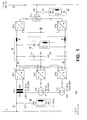
- Fig. 1 with (1) is a single-phase 16 2/3 Hz rail network or 1-phase network or AC network with an AC voltage of 110 kV and with 7 a 3-phase 50 Hz state network or 3-phase network with an AC voltage of 110 kV designated.
- the rail network (1) is connected via a switch (S1) to a voltage summing transformer which consists of 3 sub-transformers (Tr1 - Tr3) which have transformer cores that are not magnetically coupled to one another.
- Each partial transformer (Tr1 - Tr3) has a transformer winding (W1) on the mains side and a transformer winding (W2) on the converter side.
- the transformer windings on the mains side (W1) are connected in series and grounded at the ends.
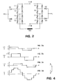
- Each converter winding on the converter side (W2) is connected via AC voltage connections to a separate 4-quadrant converter or converter or partial converter (ST1 - ST3), the circuit of which is shown in FIG. 2.
- Each of the 3 sub-transformers (Tr1 - Tr3) has a short circuit voltage of 20%.
- the partial transformers (TR1) and (Tr3) are designed for a power of 14.5 MVA and for a voltage drop of 31.8 kV, while the partial transformer (TR2) is designed for a power of 25 MVA and a voltage drop of 55 kV.
- the partial converters (ST1 - ST3) and the associated partial transformers (Tr1 - Tr3) are operated with different phase shifts or phase shifts of the converter voltages, namely with a phase shift of + 30 ° el. or 0 ° el. or -30 ° el.
- the 3 partial converters (ST1 - ST3) are designed in a 3-point circuit and connected in parallel on the DC voltage side, with a positive pole (8), a negative pole (9) and a zero pole (PO).
- the partial converters (ST1 - ST3) are connected via a DC link (3) with 2 DC converters connected in series on the DC side (ST4, ST5) connected, which are connected to the country network (7) on the AC voltage side via a winding transformer or network transformer (TR4) and a switch (S4).
- electrical energy can be transmitted from the state network (7) to the rail network (1) via the DC link (3).
- energy transfer in the opposite direction is also possible.
- the DC voltage intermediate circuit (3) has an intermediate circuit choke (5) in each DC voltage line (8, 9), furthermore 2 DC link capacitors (C1, C2) connected in series, the common connecting line of which is connected to the zero pole (P0) of the partial converters (ST1 - ST3) is, and a high-pass filter (4), the second harmonic of the rail network (1), d. H. to 33 1/3 Hz, and is designed for a reactive power of 15 MVar. If only one DC link choke (5) is provided, the zero pole (P0) must not be earthed.
- high-pass filters (2) and (6) are connected to the supply lines to the respective network transformers via switches (S2) and (S3), which are matched to the 12th harmonic of the respective power network (1) or (7) and for reactive power of 10 MVar and 15 MVar are designed; they dampen the 11th and 13th harmonics.
- the 4-quadrant actuator shown has 4 bridge branches, each with 2 GTO thyristors (T1, T2) or (T3, T4) or (T5, T6) or (T7, T8) connected in series, with antiparallel to each GTO thyristor a diode is connected.
- the connecting lines of the GTO thyristors (T2) and (T3) as well as the GTO thyristors (T6) and (T7) form the AC voltage inputs of the 4-quadrant actuator, which are connected with the transformer winding (W2) on the converter side.
- the connecting lines of the GTO thyristors (T1) and (T2) and those of the GTO thyristors (T5) and (T6) are each connected to the cathode of a zero-point diode (D0), which is connected to the zero pole (P0) on the anode side.
- the connecting lines of the GTO thyristors (T3) and (T4) and those of the GTO thyristors (T7) and (T8) are each connected to the anode of a zero-point diode (D0), which is connected on the cathode side to the zero pole (P0) .
- the transformation ratio of the partial transformers (Tr1 - Tr3) is important for achieving the desired harmonic reduction.
- the partial transformer (Tr2) delivers a ⁇ 3 times the line-side voltage in comparison to the line-side voltages of the partial transformers (Tr1, Tr3).
- the partial converters (ST1 - ST3) can be in 3-point operation according to FIGS. 1 and 2 or in 2-point operation, cf. 11, are operated, the thyristors (T1, T4, T5, T8) with associated antiparallel diodes and the zero-point diodes (D0) being omitted in the circuit of FIG. 2.
- the voltage levels are each 30 ° el. mutually shifted in phase, the amplitude of the partial voltage (U2) being ⁇ 3 times that of the other two partial voltages (U1, U3).
- FIG. 4 shows the addition of the voltage pointers assigned to the total voltage (U) according to FIG. 3d.
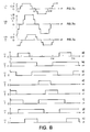
- 5a-5d show firing pulse patterns for the GTO thyristors (T2, T3, T6, T7) for generating the voltage forms of FIG. 3a by the partial converter (ST1).
- 5a and 5d show the on-times of the thyristors (T2) and (T3), while FIGS. 5b and 5c show on-times of the thyristors (T6) and (T7) which are phase-shifted by 120 °.
- the thyristors (T2) and (T3) or (T6) and (T7) are always fired alternately.
- This ignition pulse pattern results in 120 ° rectangular blocks of the converter alternating voltage which are free from harmonics of the atomic number 3, 9, 15 etc., i. H. free of harmonics that are divisible by 3.
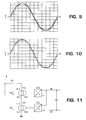
- the partial voltages (U1 - U3) of the partial transformers (Tr1 - Tr3) are around 30 ° el. offset from each other so that there is just 12 pulses with the transformer ratio mentioned, cf. 3a-3c and Fig. 10 with a computer simulation in which a Fourier analysis provides the lowest amplitudes for the 11th and 13th harmonics.
- FIGS. 6a-6c show voltage signal diagrams of a first converter system, corresponding to FIG. 1, and FIGS. 6d-6f show those of a second identical converter system, which is 15 ° el. From the first converter system. is out of phase, both without zero-point diodes (D0). This doubling results in a quasi 24-pulse reaction, cf. the computer simulation in FIG. 9.
- FIGS. 6a - 6f show voltage signal diagrams of the 3 partial transformers (Tr1 -Tr3) in a 3-point operation of the 3 connected partial converters (ST1-ST3) according to the Fig. 1 and 2.
- 3-point operation the potentials +, 0 and - of the DC voltage side are switched through alternately.
- partial converters (ST1 - ST3) according to FIG. 1 it is possible with partial converters (ST1 - ST3) according to FIG. 1 to achieve the same 24-pulse rate as with two subsystems in the two-point system according to FIGS. 6a - 6f.
- FIG 11 shows a converter circuit for two-point operation with only two partial converters (STa) and (STb), which are connected on the AC side to partial transformers (Tra) and (Trb), which generate partial voltages (Ua, Ub) on their transformer windings (W1) on the mains side.
- the partial converters (STa) and (STb) are connected in parallel.
- the transformation ratio of the line-side transformer winding (W1) to the converter-side transformer winding (W2) is 3: 1 for the partial transformer (Tra) and 1: 1 for the partial transformer (Trb).
- FIGS. 12a and 12b show voltage signal diagrams of the partial voltages (Ua) and (Ub) that can be created with a converter circuit according to FIG. 11.
- 12c shows the associated sum signal diagram from which the 6-pulse rate achieved can be seen.
- FIGS. 13a and 13b show voltage signal diagrams of the partial voltages (U1) and (U3) which can be created with a circuit according to FIG. 1 if the partial transformer (Tr2) with connected partial converter (ST2) is omitted. 13c shows the associated sum signal diagram from which the 6-pulse rate achieved can be seen.
- the partial converter (ST3) is operated with 3 potential levels, which requires more effort than a converter with 2-point operation.
- FIG. 14 shows a voltage signal diagram with an optimal stair curve of 5 voltage levels.
- the step curve generated by means of a network coupling (not shown) with 5 partial converters and 5 partial transformers should run in such a way that it approximates a sine curve (10) as well as possible.
- ( ⁇ i ) the ignition angle or the phase shift of an i. Level or an i. Partial converter and with (S i ) an i. Step height or line-side transformer partial voltage designated.
- a hatched step area below the sine curve (10) is denoted by (Fu) and a step area above the sinus curve (10), also hatched, is denoted by (Fo).
- the steps must be selected so that the total area of the step areas (Fu) below the sine curve (10) is equal to that Total area of the step areas (Fo) above the sine curve (10).
- the step height (S i ) should be greater than in areas with a smaller slope; that is, S i should be selected proportional to cos ⁇ i .
- the invention is also suitable for static compensators for compensating reactive power z. B. in the circuit of FIG. 11th
Landscapes
- Engineering & Computer Science (AREA)
- Power Engineering (AREA)
- Inverter Devices (AREA)
- Rectifiers (AREA)
Applications Claiming Priority (2)
| Application Number | Priority Date | Filing Date | Title |
|---|---|---|---|
| DE19924225269 DE4225269A1 (de) | 1992-07-31 | 1992-07-31 | Verfahren zur Dämpfung von Netzoberschwingungen und eine Netzkupplung |
| DE4225269 | 1992-07-31 |
Publications (2)
| Publication Number | Publication Date |
|---|---|
| EP0581322A2 true EP0581322A2 (fr) | 1994-02-02 |
| EP0581322A3 EP0581322A3 (fr) | 1994-08-31 |
Family
ID=6464506
Family Applications (1)
| Application Number | Title | Priority Date | Filing Date |
|---|---|---|---|
| EP93112312A Withdrawn EP0581322A2 (fr) | 1992-07-31 | 1993-07-31 | Dispositif de couplage de réseau et méthode pour amortir les harmoniques |
Country Status (2)
| Country | Link |
|---|---|
| EP (1) | EP0581322A2 (fr) |
| DE (1) | DE4225269A1 (fr) |
Cited By (7)
| Publication number | Priority date | Publication date | Assignee | Title |
|---|---|---|---|---|
| WO1996014686A1 (fr) * | 1994-11-04 | 1996-05-17 | Gec Alsthom Limited | Convertisseur multiniveau |
| WO1996016469A1 (fr) * | 1994-11-23 | 1996-05-30 | Siemens Aktiengesellschaft | Procede et dispositif permettant de reduire les perturbations du systeme d'harmoniques d'un onduleur a niveaux multiples autocommute |
| DE19646085A1 (de) * | 1996-11-08 | 1998-05-14 | Asea Brown Boveri | Stromrichterschaltungsanordnung |
| DE19647933A1 (de) * | 1996-11-20 | 1998-05-28 | Asea Brown Boveri | Leistungselektronische Schaltungsanordnung |
| EP0903843A2 (fr) * | 1997-08-22 | 1999-03-24 | Asea Brown Boveri AG | Onduleur |
| EP1715572A2 (fr) * | 2005-04-20 | 2006-10-25 | Siemens Aktiengesellschaft | Méthode pour commander un dispositif électrique |
| CN105826923A (zh) * | 2016-04-22 | 2016-08-03 | 九阳股份有限公司 | 一种抑制可控硅调压电路谐波电流的控制方法 |
Families Citing this family (1)
| Publication number | Priority date | Publication date | Assignee | Title |
|---|---|---|---|---|
| DE19536468A1 (de) * | 1995-09-29 | 1997-04-03 | Siemens Ag | Netzfreundlicher stromrichtergesteuerter, spannungseinprägender Schrägtransformator großer Leistung |
Citations (7)
| Publication number | Priority date | Publication date | Assignee | Title |
|---|---|---|---|---|
| US3581212A (en) * | 1969-07-31 | 1971-05-25 | Gen Electric | Fast response stepped-wave switching power converter circuit |
| US4052657A (en) * | 1976-04-22 | 1977-10-04 | Rockwell International Corporation | Distribution system for a. c. electrical energy derived from d. c. energy sources |
| FR2349231A1 (fr) * | 1976-04-23 | 1977-11-18 | Thomson Csf | Dispositif generateur de signaux periodiques et puissance elevee,a frequence variable et haut rendement,et systeme muni d'un tel dispositif |
| US4159513A (en) * | 1977-09-30 | 1979-06-26 | Westinghouse Electric Corp. | Static controlled AC motor drive having plug reversal capability |
| EP0254911A1 (fr) * | 1986-08-01 | 1988-02-03 | BBC Brown Boveri AG | Circuit de redresseur et procédé pour sa commande |
| DE3725923A1 (de) * | 1987-07-31 | 1989-02-09 | Licentia Gmbh | Umrichtersystem mit einer durch gleichrichter gewonnenen zwischenkreisgleichspannung |
| US5008797A (en) * | 1989-12-20 | 1991-04-16 | Sundstrand Corporation | Power converter utilizing line replaceable units |
Family Cites Families (11)
| Publication number | Priority date | Publication date | Assignee | Title |
|---|---|---|---|---|
| BE619007A (fr) * | 1961-06-19 | 1900-01-01 | ||
| NL295073A (fr) * | 1963-07-09 | |||
| DE1763325A1 (de) * | 1968-05-07 | 1971-10-21 | Lear Jet Ind Inc | Wechselstromversorgung |
| US3768000A (en) * | 1971-12-02 | 1973-10-23 | Gulton Ind Inc | Stepped sinusoidal-like waveform generating inverter circuit |
| US4063144A (en) * | 1976-03-25 | 1977-12-13 | Sundstrand Corporation | Inverter for providing a sinusodial output having a low harmonic content |
| SU826518A1 (ru) * | 1979-08-13 | 1981-04-30 | Пермский Электротехнический Завод | Блок трансформаторов дл инвертора |
| GB2113486B (en) * | 1982-01-13 | 1985-11-06 | Chromalock Ltd | Static inverter |
| DE3224222A1 (de) * | 1982-06-29 | 1983-12-29 | Siemens AG, 1000 Berlin und 8000 München | Verfahren und vorrichtung zum umschalten der stromflussrichtung eines direktumrichters, insbesondere eines drehstrom-drehstrom-umrichters |
| SU1374364A1 (ru) * | 1986-07-14 | 1988-02-15 | Пермский политехнический институт | Преобразователь переменного напр жени в посто нное с компенсацией высших гармоник тока,потребл емого от сети |
| DE4037531C2 (de) * | 1990-11-26 | 2003-11-06 | Daimlerchrysler Rail Systems | Verfahren zur Steuerung von Gleichrichtern |
| DE4113603C1 (en) * | 1991-04-23 | 1992-05-27 | Licentia Patent-Verwaltungs-Gmbh, 6000 Frankfurt, De | High-power GTO converter - uses thyristors connected in three=phase rectifier circuit |
-
1992
- 1992-07-31 DE DE19924225269 patent/DE4225269A1/de not_active Withdrawn
-
1993
- 1993-07-31 EP EP93112312A patent/EP0581322A2/fr not_active Withdrawn
Patent Citations (7)
| Publication number | Priority date | Publication date | Assignee | Title |
|---|---|---|---|---|
| US3581212A (en) * | 1969-07-31 | 1971-05-25 | Gen Electric | Fast response stepped-wave switching power converter circuit |
| US4052657A (en) * | 1976-04-22 | 1977-10-04 | Rockwell International Corporation | Distribution system for a. c. electrical energy derived from d. c. energy sources |
| FR2349231A1 (fr) * | 1976-04-23 | 1977-11-18 | Thomson Csf | Dispositif generateur de signaux periodiques et puissance elevee,a frequence variable et haut rendement,et systeme muni d'un tel dispositif |
| US4159513A (en) * | 1977-09-30 | 1979-06-26 | Westinghouse Electric Corp. | Static controlled AC motor drive having plug reversal capability |
| EP0254911A1 (fr) * | 1986-08-01 | 1988-02-03 | BBC Brown Boveri AG | Circuit de redresseur et procédé pour sa commande |
| DE3725923A1 (de) * | 1987-07-31 | 1989-02-09 | Licentia Gmbh | Umrichtersystem mit einer durch gleichrichter gewonnenen zwischenkreisgleichspannung |
| US5008797A (en) * | 1989-12-20 | 1991-04-16 | Sundstrand Corporation | Power converter utilizing line replaceable units |
Cited By (11)
| Publication number | Priority date | Publication date | Assignee | Title |
|---|---|---|---|---|
| WO1996014686A1 (fr) * | 1994-11-04 | 1996-05-17 | Gec Alsthom Limited | Convertisseur multiniveau |
| WO1996016469A1 (fr) * | 1994-11-23 | 1996-05-30 | Siemens Aktiengesellschaft | Procede et dispositif permettant de reduire les perturbations du systeme d'harmoniques d'un onduleur a niveaux multiples autocommute |
| DE19646085A1 (de) * | 1996-11-08 | 1998-05-14 | Asea Brown Boveri | Stromrichterschaltungsanordnung |
| US6052296A (en) * | 1996-11-08 | 2000-04-18 | Asea Brown Boveri Ag | Power breaker |
| DE19647933A1 (de) * | 1996-11-20 | 1998-05-28 | Asea Brown Boveri | Leistungselektronische Schaltungsanordnung |
| US5926382A (en) * | 1996-11-20 | 1999-07-20 | Asea Brown Boveri Ag | Power electronic circuit arrangement |
| EP0903843A2 (fr) * | 1997-08-22 | 1999-03-24 | Asea Brown Boveri AG | Onduleur |
| EP0903843A3 (fr) * | 1997-08-22 | 1999-06-02 | Asea Brown Boveri AG | Onduleur |
| EP1715572A2 (fr) * | 2005-04-20 | 2006-10-25 | Siemens Aktiengesellschaft | Méthode pour commander un dispositif électrique |
| EP1715572A3 (fr) * | 2005-04-20 | 2010-01-13 | Siemens Aktiengesellschaft | Méthode pour commander un dispositif électrique |
| CN105826923A (zh) * | 2016-04-22 | 2016-08-03 | 九阳股份有限公司 | 一种抑制可控硅调压电路谐波电流的控制方法 |
Also Published As
| Publication number | Publication date |
|---|---|
| DE4225269A1 (de) | 1994-02-03 |
| EP0581322A3 (fr) | 1994-08-31 |
Similar Documents
| Publication | Publication Date | Title |
|---|---|---|
| EP2100364B1 (fr) | Commande d'un convertisseur modulaire avec des accumulateurs d'énergie répartis | |
| DE10143279B4 (de) | Frequenzumrichter | |
| DE102005012371A1 (de) | Zwölfpuls-Hochspannungsgleichstromübertagung | |
| DE102008014898A1 (de) | Verfahren zur Steuerung eines mehrphasigen Stromrichters mit verteilten Energiespeichern bei niedrigen Ausgangsfrequenzen | |
| DE4037531C2 (de) | Verfahren zur Steuerung von Gleichrichtern | |
| DE19720787A1 (de) | Verfahren zum Betrieb einer leistungselektronischen Schaltungsanordnung | |
| DE2712601C2 (fr) | ||
| EP0254911A1 (fr) | Circuit de redresseur et procédé pour sa commande | |
| DE102012107122A1 (de) | Wechselrichterschaltung | |
| EP0581322A2 (fr) | Dispositif de couplage de réseau et méthode pour amortir les harmoniques | |
| EP0212172A1 (fr) | Procédé et dispositif de compensation d'oscillations de courant | |
| DE2719989C2 (de) | Pulsdauermodulationsverfahren für dreiphasige Umrichter | |
| DE3523622C2 (fr) | ||
| WO1999049559A2 (fr) | Procede et dispositif pour supprimer les parasites dans des changeurs de frequence | |
| EP0534242B1 (fr) | Méthode pour la réduction des oscillations de tension au point neutre d'un onduleur à trois niveaux | |
| WO2020043304A1 (fr) | Procédé destiné à faire fonctionner un convertisseur | |
| WO1990010339A1 (fr) | Bobine egalisatrice de courant alternatif et procede d'exploitation en parallele de deux convertisseurs de puissance | |
| DE3150385C2 (de) | Statische Netzkupplung für hohe Leistung zur Kupplung eines Dreiphasennetzes höherer Frequenz und eines Einphasennetzes mit niedrigerer Frequenz | |
| DE2646745C3 (de) | Schaltungsanordnung zur Speisung eines Gleichspannungsverbrauchers | |
| DD293469A5 (de) | Verfahren zur synchronisation mehrerer gemeinsam betriebener getakteter eingangsstromrichter | |
| DE2423601C3 (de) | Verfahren und Schaltungsanordnung zur Ansteuerung der steuerbaren Hauptventile zweier Wechselrichter | |
| WO2003026110A2 (fr) | Procede de commutation dans des convertisseurs matriciels | |
| DE102016223944A1 (de) | Anlage zum Übertragen elektrischer Leistung | |
| DE2433825A1 (de) | Verfahren zur energieversorgung und verbesserung des leistungsfaktors von wechselstromnetzen | |
| CH680888A5 (fr) |
Legal Events
| Date | Code | Title | Description |
|---|---|---|---|
| PUAI | Public reference made under article 153(3) epc to a published international application that has entered the european phase |
Free format text: ORIGINAL CODE: 0009012 |
|
| AK | Designated contracting states |
Kind code of ref document: A2 Designated state(s): AT CH DE FR LI SE |
|
| PUAL | Search report despatched |
Free format text: ORIGINAL CODE: 0009013 |
|
| AK | Designated contracting states |
Kind code of ref document: A3 Designated state(s): AT CH DE FR LI SE |
|
| 17P | Request for examination filed |
Effective date: 19950125 |
|
| 17Q | First examination report despatched |
Effective date: 19950810 |
|
| STAA | Information on the status of an ep patent application or granted ep patent |
Free format text: STATUS: THE APPLICATION HAS BEEN WITHDRAWN |
|
| 18W | Application withdrawn |
Withdrawal date: 19951102 |