US9748772B2 - Method of controlling a solar power plant, a power conversion system, a DC/AC inverter and a solar power plant - Google Patents
Method of controlling a solar power plant, a power conversion system, a DC/AC inverter and a solar power plant Download PDFInfo
- Publication number
- US9748772B2 US9748772B2 US14/765,079 US201314765079A US9748772B2 US 9748772 B2 US9748772 B2 US 9748772B2 US 201314765079 A US201314765079 A US 201314765079A US 9748772 B2 US9748772 B2 US 9748772B2
- Authority
- US
- United States
- Prior art keywords
- power
- inverter
- converter
- regulating
- array
- Prior art date
- Legal status (The legal status is an assumption and is not a legal conclusion. Google has not performed a legal analysis and makes no representation as to the accuracy of the status listed.)
- Active, expires
Links
- 238000006243 chemical reaction Methods 0.000 title claims abstract description 76
- 238000000034 method Methods 0.000 title claims abstract description 31
- 230000001105 regulatory effect Effects 0.000 claims abstract description 74
- 230000001276 controlling effect Effects 0.000 claims abstract description 25
- 238000012544 monitoring process Methods 0.000 claims abstract description 24
- 238000003491 array Methods 0.000 claims abstract description 16
- 230000005540 biological transmission Effects 0.000 claims description 25
- 238000005259 measurement Methods 0.000 claims description 10
- 230000033228 biological regulation Effects 0.000 description 20
- 230000006870 function Effects 0.000 description 12
- 238000010586 diagram Methods 0.000 description 4
- 238000012546 transfer Methods 0.000 description 3
- 230000003247 decreasing effect Effects 0.000 description 2
- 230000002708 enhancing effect Effects 0.000 description 2
- 230000001965 increasing effect Effects 0.000 description 2
- 238000004519 manufacturing process Methods 0.000 description 2
- 238000011017 operating method Methods 0.000 description 2
- 230000001131 transforming effect Effects 0.000 description 2
- 230000032683 aging Effects 0.000 description 1
- 238000004891 communication Methods 0.000 description 1
- 238000001914 filtration Methods 0.000 description 1
- 238000009434 installation Methods 0.000 description 1
- 238000009413 insulation Methods 0.000 description 1
- 238000002955 isolation Methods 0.000 description 1
- 238000013507 mapping Methods 0.000 description 1
Images


Classifications
-
- H—ELECTRICITY
- H02—GENERATION; CONVERSION OR DISTRIBUTION OF ELECTRIC POWER
- H02J—CIRCUIT ARRANGEMENTS OR SYSTEMS FOR SUPPLYING OR DISTRIBUTING ELECTRIC POWER; SYSTEMS FOR STORING ELECTRIC ENERGY
- H02J3/00—Circuit arrangements for ac mains or ac distribution networks
- H02J3/38—Arrangements for parallely feeding a single network by two or more generators, converters or transformers
- H02J3/381—Dispersed generators
-
- H02J3/385—
-
- H—ELECTRICITY
- H02—GENERATION; CONVERSION OR DISTRIBUTION OF ELECTRIC POWER
- H02M—APPARATUS FOR CONVERSION BETWEEN AC AND AC, BETWEEN AC AND DC, OR BETWEEN DC AND DC, AND FOR USE WITH MAINS OR SIMILAR POWER SUPPLY SYSTEMS; CONVERSION OF DC OR AC INPUT POWER INTO SURGE OUTPUT POWER; CONTROL OR REGULATION THEREOF
- H02M7/00—Conversion of ac power input into dc power output; Conversion of dc power input into ac power output
- H02M7/42—Conversion of dc power input into ac power output without possibility of reversal
-
- H—ELECTRICITY
- H02—GENERATION; CONVERSION OR DISTRIBUTION OF ELECTRIC POWER
- H02J—CIRCUIT ARRANGEMENTS OR SYSTEMS FOR SUPPLYING OR DISTRIBUTING ELECTRIC POWER; SYSTEMS FOR STORING ELECTRIC ENERGY
- H02J2300/00—Systems for supplying or distributing electric power characterised by decentralized, dispersed, or local generation
- H02J2300/20—The dispersed energy generation being of renewable origin
- H02J2300/22—The renewable source being solar energy
- H02J2300/24—The renewable source being solar energy of photovoltaic origin
- H02J2300/26—The renewable source being solar energy of photovoltaic origin involving maximum power point tracking control for photovoltaic sources
-
- Y—GENERAL TAGGING OF NEW TECHNOLOGICAL DEVELOPMENTS; GENERAL TAGGING OF CROSS-SECTIONAL TECHNOLOGIES SPANNING OVER SEVERAL SECTIONS OF THE IPC; TECHNICAL SUBJECTS COVERED BY FORMER USPC CROSS-REFERENCE ART COLLECTIONS [XRACs] AND DIGESTS
- Y02—TECHNOLOGIES OR APPLICATIONS FOR MITIGATION OR ADAPTATION AGAINST CLIMATE CHANGE
- Y02E—REDUCTION OF GREENHOUSE GAS [GHG] EMISSIONS, RELATED TO ENERGY GENERATION, TRANSMISSION OR DISTRIBUTION
- Y02E10/00—Energy generation through renewable energy sources
- Y02E10/50—Photovoltaic [PV] energy
- Y02E10/56—Power conversion systems, e.g. maximum power point trackers
-
- Y02E10/58—
-
- Y10T307/549—
Definitions
- the present disclosure relates to a method, a power conversion system, and a DC/AC inverter for a solar power plant.
- solar power are collected by a plurality of photovoltaic (PV) devices or panels transforming the solar power into DC (direct current) electric power, which power is subsequently converted into AC (alternating current) electric power of a power transmission system or grid.
- PV photovoltaic
- the power is collected at a low voltage by the PV panels, converted into a higher voltage and fed to the transmission system.
- a complex system is used incorporating many devices and to maximize efficiency different collecting and conversion systems have been used.
- US 2012/0274139 (E1) describes a distributed PV power plant including a plurality of distributed DC/DC converters (22 in E1), each being connected to a plurality of strings of PV panels.
- the switching of the DC/DC converters is coordinated, and their power are supplied to a common DC bus for further conversion by means of a DC/AC converter into AC power (see FIG. 1-4, claim 1 of E1).
- a higher efficiency can be provided (see ⁇ 0032, ⁇ 0036 in E1).
- Document E2 describes a solar power plant comprising photovoltaic panels (PV panels) (20 in FIG. 3 of E2), local power converters (22 in E2) and a central power converter (24 in E2). So called maximum power point tracking (MPPT) is provided for each power source, i.e. for each PV panel, by means of the local power converters (22, see ⁇ 0006, ⁇ 0021, see also FIG. 4 and FIG. 5 in E2).
- the central converter (24) also includes MPP tracking (see ⁇ 0025, claim 1 in E2), and the two methods of MPP tracking are coordinated (see ⁇ 0061, FIGS. 16-18) in E2.
- MPP tracking see ⁇ 0025, claim 1 in E2
- Such a system has benefits during for example shading, but the provision of one dedicated local converter for each panel adds costs to the overall system, especially for larger systems.
- An objective of the present disclosure to at least alleviate a problem in the prior art in respect of energy production.
- An aim of the invention is to provide high efficiency in solar power systems.
- a further aim is to provide a cost effective system.
- the present invention provides a method of controlling a solar power plant comprising photovoltaic modules (PV modules) and a power conversion system arranged to convert the power collected by the PV modules for transmission by means of an electric power transmission system.
- the conversion system comprises a plurality of DC/DC converters, a power collecting grid and a DC/AC inverter, and the PV modules are arranged in arrays of PV modules, each PV array having an interface connected to, and controlled by, a respective one of the DC/DC converters, the power collecting grid being arranged to provide an interface between the plurality of DC/DC converters and an input of the DC/AC inverter ( 6 ).
- the method comprises monitoring the performance of each PV array and performing a first mode of operation.
- the first mode of operation comprises a first step of regulating, wherein the voltage level of each interface between a PV array and the corresponding DC/DC converter is adjusted, which regulating is based on a performance model of the PV array and a theoretical efficiency of each DC/DC converter, and includes monitoring the output power of each DC/DC converter during the first step of regulating and use the monitored output power of each DC/DC converter as a feedback for controlling the first regulating step.
- the first mode of operation also comprises a second step of regulating, wherein the voltage level of the power collecting grid is adjusted, which regulating is based on a theoretical efficiency of the DC/AC inverter, and includes monitoring the output power of the DC/AC inverter, during the second step of regulating and use the monitored output power of the DC/AC inverter as a feedback for controlling the second regulating step.
- the method includes selectively employing the first mode of operation or a second mode of operation.
- the second mode of operation comprises controlling the voltage level of the power collection grid so that the DC/DC converters provide power at a predefined maximum output voltage to increase the input voltage and power of the DC/AC inverter. In this way an efficient alternative exists when the first mode encounter problems.
- the method includes switching to the second mode of operation when the input voltage, or power, of the DC/AC inverter falls below a first threshold.
- the method can function also when, for example, the power production is small and losses in the power conversion grid affect its current transferring capacity.
- the second mode of operation includes controlling the DC/DC converters to perform a maximum power point tracking of each PV array.
- the method includes updating the theoretical efficiency of each primary DC/DC converter and/or updating the theoretical efficiency of the DC/AC inverter. In this way the method adapts to varying conditions of the conversion system, such as losses in different parts of the system due to for example ageing, and failures of components. This provides a step of learning being employed to adapt the functioning automatically to different conditions.
- the method includes converting the power from the PV arrays into DC power at a medium voltage by means of the DC/DC converters.
- the medium voltage level is between 2 kV and 50 kV.
- the method includes feeding the medium voltage power to the DC/AC inverter by means of the power collecting grid.
- the present invention also provides a power conversion system for a solar power plant, adapted for converting power collected by PV modules of the solar power plant to AC power for transmission by means of an electric power transmission system.
- the power conversion system comprises a plurality of DC/DC converters, a power collecting grid and a DC/AC inverter.
- Each DC/DC converter is adapted to be connected to and control an interface to an array of PV modules.
- Each DC/DC converter may have a plurality of interfaces, each controlling an array of PV modules.
- the power collecting grid is arranged between the plurality of DC/DC converters and an input of the DC/AC inverter and provides an interface between the DC/DC converters and the DC/AC inverter.
- the conversion system further comprises at least one control unit arranged and adapted to control the conversion of power.
- the at least one control unit is adapted to monitor the performance of each PV array, and to perform a first mode of operation comprising a first and a second regulating step.
- the first step of regulating includes adjusting the voltage level of each interface between a PV array and the corresponding DC/DC converter,
- the first step of regulating is based on a performance model of the PV array and a theoretical efficiency of each DC/DC converter and includes monitoring the output power of each primary DC/DC converter and uses the monitored output power of each DC/DC converter as a feedback for the first step of regulating.
- the second step of regulating includes adjusting the voltage level of the power collecting grid.
- the second step of regulating is based on a theoretical efficiency of the DC/AC inverter and includes monitoring the output power of the DC/AC inverter and uses the monitored output power of the DC/AC inverter as a feedback for the second step of regulating.
- the at least one control unit is adapted to selectively employ the first mode of operation or a second mode of operation.
- the second mode of operation comprises controlling the DC/AC inverter to adjust its input voltage, so that the DC/DC converters provide the power at a predefined maximum output voltage.
- the at least one control unit is adapted to switch to the second mode of operation when the input power or voltage of the DC/AC inverter falls below a first threshold.
- the second mode of operation comprises controlling the DC/DC converters to perform a maximum power point tracking of each PV array.
- the at least one control unit is adapted to update the performance model of each PV array and/or the theoretical efficiency of each primary DC/DC converter and/or update the theoretical efficiency of the DC/AC inverter.
- each DC/DC converter comprises a control unit
- the at least one control unit is a central control unit that is operatively connected to each control unit of the DC/DC converters and is adapted to control the first step of regulating by instructing each control unit of the DC/DC converters.
- the DC/AC inverter comprises a control unit, and the at least one control unit is a central control unit operatively connected to the control unit of the DC/AC inverter and is adapted to control the second step of regulating by means of instructing the control unit of the DC/AC inverter.
- the power collecting grid is adapted for collecting DC power at a medium voltage level, such as between 2 kV and 50 kV, and the DC/AC inverter is a medium voltage DC/AC inverter.
- each DC/DC converter is an isolated DC/DC converter.
- a power conversion system comprises two power conversion systems as described above.
- Each of the two power conversion systems provides power by means of its respective DC/AC inverter to the power transmission system.
- the present invention also provides a DC/AC inverter for converting medium voltage DC current into medium or high voltage AC current, which DC/AC inverter is also adapted for controlling power conversion of a solar power plant.
- the DC/AC inverter controls a solar power plant comprising photovoltaic modules (PV modules) arranged in arrays of PV modules, each PV array ( 2 a - d ) being connected to a corresponding one of a plurality of DC/DC converters ( 4 a - d ), the DC/DC converters being connected in a power collecting grid to the DC/AC inverter.
- PV modules photovoltaic modules
- the DC/AC inverter comprises a control unit configured to control the DC/AC inverter.
- the control unit is configured to be connected to the plurality of the DC/DC converters, the control unit is configured to operatively control each DC/DC converter and operatively control the voltage of each respective interface to respective the PV array by means of the DC/DC converter.
- the control unit is adapted to monitor the performance of each PV array, and to perform a first mode of operation.
- the first mode of operation comprises a first step of regulating, wherein the voltage level of each interface between a PV array and the corresponding DC/DC converter is adjusted, which regulating is based on a performance model of the PV array and a theoretical efficiency of each DC/DC converter, and includes monitoring the output power of each primary DC/DC converter during the first step of regulating and using the monitored output power of each DC/DC converter as a feedback for the first step of regulating.
- the first mode of operating includes a second step of regulating.
- the second step of regulating includes adjusting the voltage level of the power collecting grid.
- the second step of regulating is based on a theoretical efficiency of the DC/AC inverter, and includes monitoring the output power of the DC/AC inverter, during the second step of regulating and using the monitored output power of the DC/AC inverter ( 6 ) as a feedback for the second step of regulating.
- control unit comprises a memory storing a performance model of each PV array, an efficiency model of each DC/DC converter, an efficiency model of the DC/AC inverter, and a model updater configured for updating each model based on measurements of the corresponding unit.
- control unit comprises a DC/DC converter regulator configured to control each DC/DC converter in accordance with the first step of regulating, and a DC/AC inverter regulator configured to control the DC/AC inverter in accordance with the second step of regulating.
- the control unit comprises a mode selector configured to switch between the first mode of operation and a second mode of operation, in which second mode of operation the DC/AC inverter is controlled to set a voltage level of the DC collection grid so that the DC/DC converters provide the output power at a predefined maximum output voltage in order to increase the input power of the DC/AC inverter.
- the present invention also provides a solar power plant that comprises a plurality of PV modules arranged and interconnected into a plurality of PV arrays, and a power conversion system of the kind described above, wherein each PV array have an interface connected to, and controlled by, a respective DC/DC converter of the power conversion system.
- FIG. 1 is a schematic illustration of a first embodiment a solar power plant with high voltage AC connection to a transmission system.
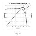
- FIG. 2 a , 2 b , 2 c are graphs illustrating the maximum power point of a PV panel.
- FIG. 3 is an illustration of a DC/DC converter efficiency contour.
- FIG. 4 is an illustration of a medium voltage DC/AC inverter efficiency contour.
- FIG. 5 is a schematic illustration of an operating method according to an embodiment of the invention.
- FIG. 6 is a schematic further illustration of an operating method according to an embodiment of the invention.
- FIG. 7 is a schematic illustration of an embodiment of a controller for a DC/AC inverter in accordance with the invention.
- FIG. 1 illustrates a solar power plant 1 comprising a plurality of PV (photovoltaic) arrays 2 a , 2 b , 2 c , 2 d , wherein each PV array 2 a - d comprises a plurality of interconnected PV panels.
- Each PV panel consists of one unit comprising interconnected photovoltaic cells.
- Each PV panel is arranged to receive energy from sun light and transform the energy into electric DC energy.
- Each PV array should typically include many PV panels, for example hundreds or more than one thousand panels to produce DC power of about 0.5-3 MW.
- each PV array 2 a - d may be between 3000 to 10000 panels, for example 8000 PV panels in 320 parallel lines with 25 PV panels serially connected in each line.
- the PV panels of each PV array 2 a - d are arranged in series and in parallel to produce the electric DC power at an output ( 3 a - d ) of about 1000 V, such as up to 1.5 kV.
- each PV panel produce 250 W and 8000 PV panels produce 2 MW.
- 320 parallel lines PV panels producing DC electric power at 3.125 V yields a total of 1 kV at the common output ( 3 a - d ) of the PV panels of each PV array 2 a - d .
- a first set of DC collection systems are provided, each of these DC collection systems being referred to as a PV array 2 a - d.
- the solar power plant 1 also comprises a plurality of DC/DC converters 4 a , 4 b , 4 c , 4 d adapted for transforming an input DC power having a lower voltage into DC power having a higher voltage, especially a high voltage or medium high voltage.
- Each DC/DC converter 4 a - d has a respective input ( 3 a - d ) connected to the output of a respective PV array 2 a - d , so that a respective interface 3 a - d between each DC/DC converter and each PV array is provided.
- the outputs of the DC/DC converters 4 a - d are serially connected to provide a DC output grid 5 at a medium voltage power level.
- the total power outputted from the connected DC/DC converters 4 a - d are provided to an input of a DC/AC inverter 6 .
- a second DC collection system, grid 5 is provided, at a medium voltage level.
- the term “medium voltage” refers to voltage levels above 2 kV and below 60 kV, especially voltage levels between 3 kV and 45 kV.
- Each DC/DC converter 4 a - d is an isolated DC/DC converter arranged to provide galvanic isolation between each PV array 2 a - d and the medium voltage DC collection grid 5 .
- the system includes arranging the DC/AC inverter 6 to receive the medium voltage DC power from the collection grid 5 by means of its DC input.
- each DC/DC converter 4 a - d is connected to a respective PV array 2 a - d at its input, and the outputs of the DC/DC converters 4 a - d are connected in series and provide a medium high voltage DC output connected to the input of the DC/AC inverter 6 , so that the second DC collection grid 5 provides an interface between the outputs of the DC/DC converters 4 a - d and the DC/AC inverter 6 .
- the output 8 of the DC/AC inverter provides AC power for subsequent transmission on an AC transmission system (not illustrated), via a transformer 12 , which transformer 12 provides galvanic insulation between the power conversion and collection system and the AC transmission system.
- the solar power plant collects solar energy and converts the produced electrical DC power from the PV arrays of low voltage DC power to a high voltage AC power at the output 8 of the medium voltage DC/AC inverter 6 by means of a DC power conversion and collection system 4 , 5 and the DC/AC inverter 6 .
- the DC/AC inverter 6 is a medium to medium voltage inverter, instead of a medium to high voltage DC/AC inverter 6 .
- This DC power conversion system comprises a set of DC/DC converters 4 a - d with a low voltage DC input, and a medium voltage DC arrangement in the form of a medium voltage DC collection grid 5 arranged for feeding DC power of medium voltage to the medium voltage DC/AC inverter 6 .
- a low voltage DC input such as up to 1000 V or 1.5 kV
- a medium voltage collection grid 5 a DC medium voltage of about 3 kV to 45 kV which in turn preferably is converted to a high voltage AC (or alternatively medium voltage AC power) of about 60 kV or more.
- the solar power plant also includes a number of control units ( 9 a - d , 10 , 14 ) being arranged and adapted for controlling the functioning of the power collection and power conversion.
- the DC/AC inverter is provided with a controller 10
- each of the DC/DC converters is provided with a respective controller 9 a - d .
- Each controller 9 a - d of the DC/DC converters 4 a - d is adapted for controlling the conversion of low voltage DC, from each respective array, into the medium voltage DC power that is collected by means of the serial interconnection of the DC collection grid 5 and fed to the DC/AC inverter 6 .
- the DC/AC inverter 6 is provided with a controller 10 adapted for converting medium voltage DC power into AC power of a high, or medium, voltage level in accordance with the AC transmission grid.
- the power system also includes a central controller 14 , which is communicatively connected to each “local” controller 9 a - d of each DC/DC converter 4 a - d and the controller 10 of the DC/AC inverter 6 .
- the central controller 14 is adapted to obtain, or receive, operating information of each DC/DC converter 4 a - d and the DC/AC inverter 6 , which operating information is obtained at the respective inputs and outputs of the converters 4 a - d and inverter 6 .
- the Controller 14 is adapted to use the measurements and operating information provided from the local control units 9 , 10 to perform an overall system control to obtain an overall power efficient operation of the whole power conversion system and the solar power plant.
- FIG. 7 suggests implementing the central control functions in the control unit 10 of the DC/AC inverter 6 .
- FIGS. 2 a - c illustrates the maximum power point of a PV panel or PV module. These figures illustrate the relationship between the voltage of a PV module and the current and power of the PV module.
- the invention suggests controlling a PV array, i.e. arrays 2 a - d of PV modules connected in series and parallel.
- the control of such a PV array 2 a - d can utilise corresponding relationships for a PV array 2 a - d of PV modules, which array relationships are determined by summarizing the relationships of the PV modules of the PV array 2 a - d .
- the relationship so obtained provides a description, or model, of the performance of the PV array 2 a - d at varying voltage and power levels.
- FIG. 2 a is a current-voltage curve that illustrates how the current fed from a PV module varies with a voltage applied to the output of the PV module.
- FIG. 2 b is a power-voltage curve and illustrates how the power from the PV module varies with the applied voltage.
- FIG. 2 c illustrates both the current-voltage and the power-voltage curves. The point where the transferred power has a maximum is indicated in each curve. This is the maximum power point and for each state of the PV module the maximum power point can be tracked to provide the maximum power output of that state. However, tracking the maximum power output of the PV module may not lead to the maximum power output of a total conversion system or a whole solar power plant.
- the conversion system of a solar power plant should be dimensioned to transfer as much power as possible to the power transmission system or power grid. Also the efficiency of the power conversion system of the solar power plant varies with different voltages and power levels. The power conversion system may therefore operate in a non-optimal state even if the PV modules operate at the maximum power point.
- the invention provides systems and methods for matching the efficiency of the PV modules and the conversion system to reach an overall maximum power transfer from the PV modules to the power transmission grid.
- FIG. 2 c also indicate operating points, A and B, of a PV module, which operating points A, B, differ from the maximum power point (MPP) of the PV module.
- MPP maximum power point
- FIG. 2 c also indicate operating points, A and B, of a PV module, which operating points A, B, differ from the maximum power point (MPP) of the PV module.
- MPP maximum power point
- the embodiments of the present invention considers the total efficiency of the conversion system and may therefore regulate one or more of the PV arrays 2 a - d to operate at an operating point A, B that differ from the MPP.
- FIG. 3 and FIG. 4 illustrates the efficiencies of the DC/DC converters and the DC/AC inverter of the system of FIG. 1 .
- the FIGS. 3 and 4 illustrate efficiency levels for different power levels and input voltages, and indicate the efficiency levels as areas within each diagram.
- the DC/DC converter is dimensioned to provide the highest efficiency at 800 V.
- the DC/AC inverter is dimensioned to provide the best efficiency for about 2.75 kV.
- the voltage of the PV modules 2 a - d (in FIG. 1 ) which is the input voltage of the DC/DC converter 4 a - d (in FIG.
- the embodiments of the invention employs both a performance model of each PV array 2 a - d , such as the power and voltage relationship of FIG. 2 c , and a theoretical efficiency, model, as in FIG. 3 , of each DC/DC converter 4 a - d when regulating the interface between each DC/DC converter 4 a - d and each PV array 2 a - d.
- FIG. 3 illustrates an operating point of a PV array 2 a - d , which operating point C is indicated in, or mapped into, the efficiency diagram of the DC/DC converter 4 a - d .
- the embodiments of the invention consider regulating the conversion system, in this case the DC/DC converter, to raise the efficiency of the DC/DC converter, by moving such an operating point C.
- the embodiments therefore monitor the interface between different devices of the system, such as between the PV array 2 a - d and the DC/DC converters 4 a - d and regulates the voltage of the interface in view of both devices.
- this regulation may suitably be made considering also the voltage and power relationship, or performance model, of the PV array 2 a - d in question.
- the conversion system is adapted to monitor the power output from the DC/DC converter 4 a - d while adjusting the operating point of the interface of the PV array 2 a - d , which adjustment is based on considering the performance model, determined by the voltage and power relationship, of the PV array and the theoretical efficiency, illustrated in FIG. 3 , of the DC/DC converter.
- the conversion system is adapted to provide each regulation of the operating point of the PV array 2 a - d either in sequence, for example first regulating based on the power voltage relationship of the PV array 2 a - d followed by a regulation of the operating point C based on the voltage and power relationship of the DC/DC converter 4 a - d , or preferably in combination, wherein the regulation is based on a theoretically determined mapping of the performance model, or voltage and power relationship, of the PV array onto the theoretical efficiency, or the power and voltage relationship, of the DC/DC converter.
- the efficiencies described in FIGS. 3 and 4 of the relationship of the voltage and power of the DC/DC converter and DC/AC inverter is a theoretical model, which however may be provided by measurements, and the described embodiments includes a regular update of these theoretical models by means of measurements performed in the conversion system.
- the theoretical models of the efficiencies may, in accordance with these embodiments, be defined in the conversion system during installation and be subsequently updated during operation.
- FIG. 4 illustrate the efficiency of the DC/AC inverter 6 , wherein the diagram illustrates the relationship between different DC input voltages and the power.
- the output voltage such as at a high voltage, is determined by the transmission grid or transmission link to which the output of the DC/AC inverter 6 is connected.
- An operating point D is illustrated in the diagram, which corresponds to a voltage level and power level being received at the input of the DC/AC inverter 6 by means of the interface defined by the DC collection grid 5 .
- the conversion system of the embodiments is adapted to regulate the operating point D to provide an enhanced efficiency, which regulation is based on the theoretical efficiency, or relationship, between the input voltage and power of the DC/AC inverter 6 , as illustrated in FIG. 4 .
- the system is adapted to perform an adjustment of the input voltage of the DC/AC inverter 6 to enhance the efficiency.
- the input voltage may be adjusted by means of the central controller 14 instructing each local control unit 9 a - d of each DC/DC converter 4 a - d to adapt their respective output voltage to provide the determined input voltage in accordance with the adjustment of the DC/AC inverter 6 .
- the embodiments of the invention disclose a regulation for enhancing the efficiency of the power conversion that is carried out in two steps.
- a first step is performed, wherein the output power of each PV array 2 a - d is regulated by the corresponding DC/DC converter 4 a - d on the basis of the monitored performance of the PV array 2 a - d , the performance model of the array 2 a - d and the theoretical efficiency of the DC/DC converter 4 a - d .
- a second step is performed, wherein the input power of the DC/AC converter 6 is regulated in cooperation by all the DC/DC converters 4 a - d connected to the input of the DC/AC inverter 6 , and which regulation is based on the theoretical efficiency model of the DC/AC inverter 6 .
- the output power of the DC/DC converter is monitored during the regulation.
- the output power of the DC/AC inverter is monitored during the regulation. In this way the system can track a maximum efficiency by adjusting the operating points of all the interfaces in the system.
- a straightforward implementation of the first step is to regulate the input voltage at the input terminals of each DC/DC converter 4 a - d , which correspond to the voltage of the PV array 2 a - d , in accordance with a theoretical model of the relationship between the voltage and power of the combination of the PV array 2 a - d and the (respective) DC/DC converter 4 a - d of the PV array 2 a - d .
- a straightforward implementation of the second step is to regulate the input voltage of the DC/AC inverter 6 based on the theoretical efficiency of the DC/AC inverter 6 , which regulation is performed by means of the DC/AC inverter adjusting the voltage level of the DC collection grid 5 so that the output voltage of each DC/DC converters 4 a - d is regulated to achieve a suitable total voltage input as fed through the collection grid 5 to the DC/AC inverter 6 .
- FIGS. 5 and 6 illustrates an embodiment of power conversion in accordance with the invention. This embodiment includes two different modes of operation. The first operating mode is illustrated in FIG. 5 , and the second operating mode id illustrated in FIG. 6 .
- the first operating mode (operating mode 1 ) illustrated in FIG. 5 describes the two steps of regulating the power conversion for increasing efficiency as mentioned above.
- Operating mode 1 includes a step of considering switching to the second mode of operation, operating mode 2 , which is illustrated in FIG. 6 .
- Operating mode 1 starts with monitoring 101 the power from each PV array 2 a - d , the power through each DC/DC converter 4 a - d fed by means of the collection grid 5 and the power outputted from the DC/AC inverter 6 .
- Mode 1 also includes monitoring the input voltage at the input terminals of the DC/AC inverter 6 . This monitoring is made to determine if a switch to operating mode 2 should be done. Thus, operating mode 1 continues with determining if the input voltage is too low, i.e. below a first threshold level.
- the threshold level is set to discover when power losses of the power collecting grid 5 becomes too large, and in such a case switch to the second operating mode 2 for better efficiency.
- the system is adapted to switch to operating mode 2 , step 104 , in accordance with operating mode 1 .
- operating mode 1 continues with two steps of regulating.
- the interface 3 a - d between each PV array 2 a - d and each respective DC/DC converter 4 a - d is regulated by adjusting the voltage of the interface.
- the operating voltage of each PV array 2 a - d is controlled.
- step 105 the voltage level is adjusted based on a performance model of the PV array 2 a - d and a theoretical efficiency model of each respective DC/DC converter 4 a - d , and the regulation step 105 is performed in accordance with the performance models of both the PV array 2 a - d in question and of the theoretical efficiency of the corresponding DC/DC converter 4 a - d .
- the theoretical models, or their combination are used to determine whether the voltage should be increased or decreased.
- the regulation step 105 of the operating point of the interface 3 a - d includes evaluating the regulating by monitoring the output power of the respective DC/DC converter 4 a - d to determine if the new operating point is better.
- the successfulness of varying the voltage is determined. This is performed by providing the monitored output power of each DC/DC converter 4 a - d as a feedback when adjusting the voltage of the respective interfaces 3 a - d of each PV array 2 a - d .
- An increase in output power is considered a successful regulation and the new operating point is maintained.
- a decrease in the output power, when moving to a new operating point is considered an un-successful regulation and the decrease in power is counteracted by a return to the previous operating point.
- step 106 the operating point of the interface 5 between the output of all the DC/DC converters 4 a - d and the input of the DC/AC inverter 6 is regulated.
- This regulation step 106 is based on the theoretical performance of the DC/AC inverter 6 .
- Regulating step 106 includes evaluating the regulation of the operating point of the interface between the DC/DC converters 4 a - d and the DC/AC inverter 6 by monitoring the output power of the DC/AC inverter 6 . A feedback of the monitored output power and/or its variation is provided in the regulation step 106 . Thus, the regulation is adjusted on the basis of the output power from the DC/AC inverter 6 .
- Operating mode 1 includes an optional step of updating the theoretical models of the performances of each PV array 2 a - d , of the efficiencies of each DC/DC converter 4 a - d and of the efficiency of the DC/AC inverter 6 . This is done by means of the measurements in the system such as including measurements of the voltages and currents of each PV array 2 a - d output, such as measured at the corresponding DC/DC converter input 4 a - d , each DC/DC converter 4 a - d input and output and the input and output of the DC/AC inverter 6 .
- FIG. 6 illustrates operating mode 2 , which is used when the input voltage, or power, of the DC/AC inverter 6 falls below a threshold that can be interpreted as corresponding to a too small power from the PV arrays 2 a - d in relation to power losses of the conversion system so that a tracking of a maximum power point of the total conversion system cannot be performed.
- the power or current is monitored.
- the method of operation may then switch to an operating mode 2 of keeping the input voltage of the DC/AC inverter 6 at a high level to keep down the power losses of the DC collection grid 5 .
- Operating mode 2 suitably starts with tracking the maximum power points of each PV array 2 a - d to provide a maximum input power into the conversion system.
- the DC/DC converters 4 a - d are regulated for providing a predefined maximum voltage input at the DC/AC inverter 6 .
- the input voltage of the DC/AC inverter 6 is monitored, in step 303 , and operating mode 2 is continued until the operating point of power and input voltage of the DC/AC inverter 6 reaches above a second threshold in which case the operation of the conversion system returns to operating mode 1 .
- operating mode 2 includes a step 304 of determining if the power and/or input voltage are/is above a second threshold, in which case the operating mode 2 continues with step 305 .
- the operating mode 2 continues by returning to the step 301 of tracking the maximum power point of each PV array 2 a - d followed by the step of regulating 302 the DC/DC converters 4 a - d to increase the power and/or input voltage of the DC/AC inverter 6 .
- step 304 the power or voltage is determined in step 304 to having reach above the second threshold
- step 305 of switching to operating mode 1 .
- Both the operating modes may suitably be performed by means of the central controller 14 communicatively and operatively connected to each local control unit 9 a - d , 10 and which controller 14 may be adapted to perform the method steps by instructing each respective control unit 9 a - d , 10 to provide measurements and perform the control of each respective device, i.e. each respective DC/DC converter or the DC/AC inverter, in accordance with the described methods.
- FIG. 7 illustrates an embodiment wherein a control unit 10 of a DC/AC inverter 6 provides a central control of the power conversion system. A central control unit 14 may then be omitted.
- FIG. 7 provides an illustration of the main functions of the embodiment when the invention is implemented, but has been simplified and do not illustrate the basic functions of a DC/AC inverter for providing the power conversion from DC to AC as such. These functions can suitably be implemented as software that when executed in the DC/AC inverter control unit 10 controls the control unit 10 to control the DC/AC inverter to provide the functions in the disclosed method.
- the control unit 10 of the DC/AC inverter comprises a communication interface 70 for communicating and operatively controlling the DC/AC inverter 6 and the DC/DC converters 4 a - d as well as receiving measurements from the inputs and outputs of each DC/DC converter 4 a - d and the DC/AC inverter 6 .
- the control unit 10 includes a main controller 71 , such as a computer with processor and memory, for effectuating the specific functions.
- the main controller 71 includes a PV array monitorer 72 , a DC/DC converter monitorer 73 and a DC/AC inverter monitorer 74 so that the control unit 10 is configured to monitor the voltages and currents (or voltages and powers) of each respective device, i.e.
- the main controller 71 is also configured with a number of theoretical models and configured to use the models for performing the regulating steps; i.e. a PV array performance model 75 , a DC/DC converter efficiency model 76 and a DC/AC inverter efficiency model 77 . As described in relation to the method, these theoretical models should be updated during operation, and for this purpose, the main controller 71 comprises a model updater 78 , provided to update each model 75 , 76 , 77 in view of the measurements provided by the monitoring elements 72 , 73 , 74 .
- the main controller also includes two regulators 79 , 82 , each having two modes of operation; mode 1 and mode 2 , respectively, which modes are selected by means of a mode selector 85 .
- the first regulator is a DC/DC converter regulator 82 configured to control each of the DC/DC converters 4 a - d in accordance with the method of the invention, operating according to mode 1 and mode 2 .
- the DC/DC converter regulator 79 is configured to use, in mode 1 , the voltages and currents of each PV array 2 a - d as provided by means of the PV array monitorer 72 to regulate each DC/DC converter 4 a - d .
- the DC/DC converter regulator 79 is also configured to use the performance model 75 of each PV array 2 a - d and the efficiency model 76 of each DC/DC converter 4 a - d , to regulate the voltage of the interface between each PV array 2 a - d and each DC/DC converter 4 a - d by means of using the output voltage of each DC/DC converter 4 a - d as feedback, which output voltage is provided by means of the DC/DC converter monitorer 73 .
- the DC/DC converter regulator 79 is configured to use, in mode 2 , the voltages and currents of each PV array 2 a - d as provided by the PV monitorer 72 together with the performance model of the PV array 75 to perform a maximum power point tracking of each PV array 2 a - d.
- the DC/AC inverter 6 is controlled by the DC/AC inverter regulator 82 to set the collection grid 5 voltage at a predefined maximum level, in mode 2 .
- the DC/AC inverter regulator 82 is configured to regulate the voltage of the conversion grid 5 , or input of the DC/AC inverter 6 on the bases of the theoretical efficiency model 77 of the DC/AC inverter 6 , while using the monitored output voltage, as provided by the DC/AC monitorer 74 , as a feedback for the regulation.
- the DC/AC inverter regulator is configured to monitor the input in view of the theoretical efficiency model 77 , or differently described, to map the input operating point of the conversion grid 5 on the efficiency model 77 of the DC/AC inverter 6 , and using the monitored output of the DC/AC inverter, as monitored by means of the DC/AC inverter monitorer 76 , as a feedback for the regulation.
- the main controller 71 may also suitably include means for monitoring or receiving information of the transmission grid, such as reactive power, and may provide compensation of reactive power, or provide filtering functions, in the transmission grid; however such functioning is not described in this disclosure.
- the main controller 71 also includes a mode selector 85 configured for providing the switching between operating mode 1 and operating mode 2 .
- the mode selector being configured to use input voltage and current/power of the DC/AC inverter 6 , as obtained by the DC/AC inverter monitorer 74 , for selecting operating mode based on a criteria, such as a threshold level for the input voltage, and/or current and/or power.
- FIG. 7 illustrates the alternative embodiment of the central control functions that a central control unit 14 should perform to when regulating the power conversion system.
- the central control unit 14 controls the DC/AC inverter via its “local” control unit 10 .
Abstract
Description
Claims (21)
Applications Claiming Priority (1)
| Application Number | Priority Date | Filing Date | Title |
|---|---|---|---|
| PCT/EP2013/052967 WO2014124672A1 (en) | 2013-02-14 | 2013-02-14 | Method of controlling a solar power plant, a power conversion system, a dc/ac inverter and a solar power plant |
Publications (2)
| Publication Number | Publication Date |
|---|---|
| US20150372490A1 US20150372490A1 (en) | 2015-12-24 |
| US9748772B2 true US9748772B2 (en) | 2017-08-29 |
Family
ID=47714116
Family Applications (1)
| Application Number | Title | Priority Date | Filing Date |
|---|---|---|---|
| US14/765,079 Active 2033-07-19 US9748772B2 (en) | 2013-02-14 | 2013-02-14 | Method of controlling a solar power plant, a power conversion system, a DC/AC inverter and a solar power plant |
Country Status (5)
| Country | Link |
|---|---|
| US (1) | US9748772B2 (en) |
| EP (1) | EP2957014B1 (en) |
| CN (1) | CN105144530B (en) |
| SA (1) | SA114350162B1 (en) |
| WO (1) | WO2014124672A1 (en) |
Cited By (3)
| Publication number | Priority date | Publication date | Assignee | Title |
|---|---|---|---|---|
| US20180262012A1 (en) * | 2015-10-19 | 2018-09-13 | Sumitomo Electric Industries, Ltd. | Power conversion device and control method thereof |
| US10637253B2 (en) | 2016-11-10 | 2020-04-28 | Sungrow Power Supply Co., Ltd. | Cooperative control method and device for photovoltaic optimizer and photovoltaic inverter |
| EP3780314B1 (en) * | 2018-11-15 | 2023-08-30 | Huawei Digital Power Technologies Co., Ltd. | Method and device for tracking maximum power point |
Families Citing this family (46)
| Publication number | Priority date | Publication date | Assignee | Title |
|---|---|---|---|---|
| US10693415B2 (en) | 2007-12-05 | 2020-06-23 | Solaredge Technologies Ltd. | Testing of a photovoltaic panel |
| US11881814B2 (en) | 2005-12-05 | 2024-01-23 | Solaredge Technologies Ltd. | Testing of a photovoltaic panel |
| US11728768B2 (en) | 2006-12-06 | 2023-08-15 | Solaredge Technologies Ltd. | Pairing of components in a direct current distributed power generation system |
| US8947194B2 (en) | 2009-05-26 | 2015-02-03 | Solaredge Technologies Ltd. | Theft detection and prevention in a power generation system |
| US8013472B2 (en) | 2006-12-06 | 2011-09-06 | Solaredge, Ltd. | Method for distributed power harvesting using DC power sources |
| US8319471B2 (en) | 2006-12-06 | 2012-11-27 | Solaredge, Ltd. | Battery power delivery module |
| US8473250B2 (en) | 2006-12-06 | 2013-06-25 | Solaredge, Ltd. | Monitoring of distributed power harvesting systems using DC power sources |
| US11735910B2 (en) | 2006-12-06 | 2023-08-22 | Solaredge Technologies Ltd. | Distributed power system using direct current power sources |
| US11687112B2 (en) | 2006-12-06 | 2023-06-27 | Solaredge Technologies Ltd. | Distributed power harvesting systems using DC power sources |
| US8319483B2 (en) | 2007-08-06 | 2012-11-27 | Solaredge Technologies Ltd. | Digital average input current control in power converter |
| US11309832B2 (en) | 2006-12-06 | 2022-04-19 | Solaredge Technologies Ltd. | Distributed power harvesting systems using DC power sources |
| US8963369B2 (en) | 2007-12-04 | 2015-02-24 | Solaredge Technologies Ltd. | Distributed power harvesting systems using DC power sources |
| US8384243B2 (en) | 2007-12-04 | 2013-02-26 | Solaredge Technologies Ltd. | Distributed power harvesting systems using DC power sources |
| US11855231B2 (en) | 2006-12-06 | 2023-12-26 | Solaredge Technologies Ltd. | Distributed power harvesting systems using DC power sources |
| US8816535B2 (en) | 2007-10-10 | 2014-08-26 | Solaredge Technologies, Ltd. | System and method for protection during inverter shutdown in distributed power installations |
| US11569659B2 (en) | 2006-12-06 | 2023-01-31 | Solaredge Technologies Ltd. | Distributed power harvesting systems using DC power sources |
| US9088178B2 (en) | 2006-12-06 | 2015-07-21 | Solaredge Technologies Ltd | Distributed power harvesting systems using DC power sources |
| CN101933209B (en) | 2007-12-05 | 2015-10-21 | 太阳能安吉有限公司 | Release mechanism in distributed electrical power apparatus, to wake up and method for closing |
| US11264947B2 (en) | 2007-12-05 | 2022-03-01 | Solaredge Technologies Ltd. | Testing of a photovoltaic panel |
| US8049523B2 (en) | 2007-12-05 | 2011-11-01 | Solaredge Technologies Ltd. | Current sensing on a MOSFET |
| WO2009136358A1 (en) | 2008-05-05 | 2009-11-12 | Solaredge Technologies Ltd. | Direct current power combiner |
| GB2485527B (en) | 2010-11-09 | 2012-12-19 | Solaredge Technologies Ltd | Arc detection and prevention in a power generation system |
| US10673229B2 (en) | 2010-11-09 | 2020-06-02 | Solaredge Technologies Ltd. | Arc detection and prevention in a power generation system |
| GB2483317B (en) | 2011-01-12 | 2012-08-22 | Solaredge Technologies Ltd | Serially connected inverters |
| US8570005B2 (en) | 2011-09-12 | 2013-10-29 | Solaredge Technologies Ltd. | Direct current link circuit |
| GB2498365A (en) | 2012-01-11 | 2013-07-17 | Solaredge Technologies Ltd | Photovoltaic module |
| GB2498791A (en) | 2012-01-30 | 2013-07-31 | Solaredge Technologies Ltd | Photovoltaic panel circuitry |
| US10115841B2 (en) * | 2012-06-04 | 2018-10-30 | Solaredge Technologies Ltd. | Integrated photovoltaic panel circuitry |
| US10038321B2 (en) | 2014-10-02 | 2018-07-31 | First Solar, Inc. | System for operation of photovoltaic power plant and DC power collection within |
| US10326277B2 (en) * | 2015-06-26 | 2019-06-18 | Enphase Energy, Inc. | Hierarchical control of a plurality of power subsystems and method of operating the same |
| US10256732B2 (en) | 2015-10-16 | 2019-04-09 | General Electric Company | Power conversion system and method of operating the same |
| CN105759893A (en) * | 2016-02-26 | 2016-07-13 | 西安交通大学 | Photovoltaic optimization module based on DPP structure and control method thereof |
| US11177663B2 (en) | 2016-04-05 | 2021-11-16 | Solaredge Technologies Ltd. | Chain of power devices |
| US11018623B2 (en) | 2016-04-05 | 2021-05-25 | Solaredge Technologies Ltd. | Safety switch for photovoltaic systems |
| CN106295863B (en) * | 2016-08-02 | 2020-02-07 | 南京南瑞继保电气有限公司 | New energy power station auxiliary power prediction and generated power application method and system |
| US10965126B2 (en) * | 2017-05-01 | 2021-03-30 | Futurewei Technologies, Inc. | Systems and methods for control of photovoltaic arrays |
| US10536002B2 (en) | 2017-05-12 | 2020-01-14 | Futurewei Technologies, Inc. | Power systems with inverter input voltage control |
| EP3472914B1 (en) * | 2017-05-15 | 2020-06-10 | Dynapower Company Llc | Energy storage system for photovoltaic energy and method of storing photovoltaic energy |
| US10673246B2 (en) * | 2017-11-13 | 2020-06-02 | Futurewei Technologies, Inc. | System and device for exporting power, and method of configuring thereof |
| US11289916B2 (en) * | 2018-02-07 | 2022-03-29 | Signify Holding B.V. | Lighting system and method |
| US10951040B2 (en) * | 2018-04-27 | 2021-03-16 | Nextracker Inc. | DC/DC converter for distributed storage and solar systems |
| AU2019298314A1 (en) | 2018-07-05 | 2021-01-21 | Abb Schweiz Ag | Technologies for solar power system performance model tuning |
| WO2020146999A1 (en) * | 2019-01-15 | 2020-07-23 | Abb Schweiz Ag | Pv power converter and control method and pv power plant using the same |
| US11101658B2 (en) | 2019-01-18 | 2021-08-24 | Non-Synchronous Energy Electronics, Llc | Techniques for electric power distribution and a system implementing the same |
| CN114204903A (en) * | 2020-09-18 | 2022-03-18 | 广州中旭新能源有限公司 | Photovoltaic module with intelligently optimized region and power generation system thereof |
| ES2957636A1 (en) * | 2022-04-27 | 2024-01-23 | Power Electronics Espana S L | INVERTER WITH DC/DC CONVERTER SCALABLE VOLTAGE BOOST (Machine-translation by Google Translate, not legally binding) |
Citations (10)
| Publication number | Priority date | Publication date | Assignee | Title |
|---|---|---|---|---|
| US20100288327A1 (en) | 2009-05-13 | 2010-11-18 | National Semiconductor Corporation | System and method for over-Voltage protection of a photovoltaic string with distributed maximum power point tracking |
| WO2010131245A1 (en) | 2009-05-12 | 2010-11-18 | Ramot At Tel Aviv University Ltd. | System and method for controlling a group of photovoltaic generators |
| US20110160930A1 (en) | 2009-12-31 | 2011-06-30 | Azuray Technologies, Inc. | Power Point Tracking |
| US20110232714A1 (en) | 2010-03-23 | 2011-09-29 | Vijay Bhavaraju | Power conversion system and method providing maximum efficiency of power conversion for a photovoltaic system, and photovoltaic system employing a photovoltaic array and an energy storage device |
| US20110264288A1 (en) | 2010-04-26 | 2011-10-27 | Sayed Ali Khajehoddin | Maximum Power Point Tracking for a Power Generator |
| US20120161526A1 (en) | 2010-12-28 | 2012-06-28 | Delta Electronics, Inc. | Dc power source conversion modules, power harvesting systems, junction boxes and methods for dc power source conversion modules |
| US20120187766A1 (en) | 2010-09-23 | 2012-07-26 | Hybridine Power Electronics Inc. | Device and Method For Improving The Performance Of An Inverter In A Photovoltaic System |
| US20120205974A1 (en) | 2011-02-10 | 2012-08-16 | Mccaslin Shawn R | Regulation of Inverter DC Input Voltage in Photovoltaic Arrays |
| US20120212066A1 (en) | 2006-12-06 | 2012-08-23 | Solaredge Technologies Ltd. | Safety Mechanisms, Wake Up and Shutdown Methods in Distributed Power Installations |
| US20120274139A1 (en) | 2011-04-29 | 2012-11-01 | General Electric Company | Switching coordination of distributed dc-dc converters for highly efficient photovoltaic power plants |
Family Cites Families (1)
| Publication number | Priority date | Publication date | Assignee | Title |
|---|---|---|---|---|
| US20120080943A1 (en) * | 2010-09-30 | 2012-04-05 | Astec International Limited | Photovoltaic Power Systems |
-
2013
- 2013-02-14 CN CN201380073067.1A patent/CN105144530B/en active Active
- 2013-02-14 EP EP13704117.4A patent/EP2957014B1/en active Active
- 2013-02-14 WO PCT/EP2013/052967 patent/WO2014124672A1/en active Application Filing
- 2013-02-14 US US14/765,079 patent/US9748772B2/en active Active
-
2014
- 2014-01-07 SA SA114350162A patent/SA114350162B1/en unknown
Patent Citations (10)
| Publication number | Priority date | Publication date | Assignee | Title |
|---|---|---|---|---|
| US20120212066A1 (en) | 2006-12-06 | 2012-08-23 | Solaredge Technologies Ltd. | Safety Mechanisms, Wake Up and Shutdown Methods in Distributed Power Installations |
| WO2010131245A1 (en) | 2009-05-12 | 2010-11-18 | Ramot At Tel Aviv University Ltd. | System and method for controlling a group of photovoltaic generators |
| US20100288327A1 (en) | 2009-05-13 | 2010-11-18 | National Semiconductor Corporation | System and method for over-Voltage protection of a photovoltaic string with distributed maximum power point tracking |
| US20110160930A1 (en) | 2009-12-31 | 2011-06-30 | Azuray Technologies, Inc. | Power Point Tracking |
| US20110232714A1 (en) | 2010-03-23 | 2011-09-29 | Vijay Bhavaraju | Power conversion system and method providing maximum efficiency of power conversion for a photovoltaic system, and photovoltaic system employing a photovoltaic array and an energy storage device |
| US20110264288A1 (en) | 2010-04-26 | 2011-10-27 | Sayed Ali Khajehoddin | Maximum Power Point Tracking for a Power Generator |
| US20120187766A1 (en) | 2010-09-23 | 2012-07-26 | Hybridine Power Electronics Inc. | Device and Method For Improving The Performance Of An Inverter In A Photovoltaic System |
| US20120161526A1 (en) | 2010-12-28 | 2012-06-28 | Delta Electronics, Inc. | Dc power source conversion modules, power harvesting systems, junction boxes and methods for dc power source conversion modules |
| US20120205974A1 (en) | 2011-02-10 | 2012-08-16 | Mccaslin Shawn R | Regulation of Inverter DC Input Voltage in Photovoltaic Arrays |
| US20120274139A1 (en) | 2011-04-29 | 2012-11-01 | General Electric Company | Switching coordination of distributed dc-dc converters for highly efficient photovoltaic power plants |
Non-Patent Citations (2)
| Title |
|---|
| International Preliminary Report on Patentability Application No. PCT/EP2013/052967 Completed: Jan. 29, 2015 19 pages. |
| International Search Report and Written Opinion of the International Searching Authority Application No. PCT/EP2013/052967 Completed: Mar. 22, 2013; Mailing Date: Apr. 3, 2013 11 pages. |
Cited By (4)
| Publication number | Priority date | Publication date | Assignee | Title |
|---|---|---|---|---|
| US20180262012A1 (en) * | 2015-10-19 | 2018-09-13 | Sumitomo Electric Industries, Ltd. | Power conversion device and control method thereof |
| US10637253B2 (en) | 2016-11-10 | 2020-04-28 | Sungrow Power Supply Co., Ltd. | Cooperative control method and device for photovoltaic optimizer and photovoltaic inverter |
| EP3780314B1 (en) * | 2018-11-15 | 2023-08-30 | Huawei Digital Power Technologies Co., Ltd. | Method and device for tracking maximum power point |
| EP4293896A3 (en) * | 2018-11-15 | 2024-02-14 | Huawei Digital Power Technologies Co., Ltd. | Method and device for tracking maximum power point |
Also Published As
| Publication number | Publication date |
|---|---|
| EP2957014B1 (en) | 2016-12-07 |
| SA114350162B1 (en) | 2016-11-06 |
| US20150372490A1 (en) | 2015-12-24 |
| CN105144530A (en) | 2015-12-09 |
| WO2014124672A1 (en) | 2014-08-21 |
| CN105144530B (en) | 2017-04-26 |
| EP2957014A1 (en) | 2015-12-23 |
Similar Documents
| Publication | Publication Date | Title |
|---|---|---|
| US9748772B2 (en) | Method of controlling a solar power plant, a power conversion system, a DC/AC inverter and a solar power plant | |
| US11334104B2 (en) | Circuit for interconnected direct current power sources | |
| EP2549635B1 (en) | Distributed power harvesting systems using DC power sources | |
| EP2362519B1 (en) | System and Method for a Single Stage Power Conversion System | |
| US8384243B2 (en) | Distributed power harvesting systems using DC power sources | |
| US8358033B2 (en) | Systems, methods, and apparatus for converting DC power to AC power | |
| US9350166B2 (en) | High voltage energy harvesting and conversion renewable energy utility size electric power systems and visual monitoring and control systems for said systems | |
| KR102283826B1 (en) | PV module serial/parallel conversion system for MPPT operating voltage optimization based on machine learning | |
| CN107154647B (en) | Power derating method and controller of photovoltaic power generation system | |
| US9819182B1 (en) | Systemic optimization of photovoltaic apparatus | |
| CN110301081B (en) | Distributed/centralized optimizer architecture | |
| JP7274419B2 (en) | Solar power system | |
| US8358489B2 (en) | Smart photovoltaic panel and method for regulating power using same | |
| EP2436094A1 (en) | Apparatus and method for managing and conditioning photovoltaic power harvesting systems | |
| WO2014121826A1 (en) | Solar power plant, method of controlling a solar power plant and a dc/dc conversion system | |
| EP2546947B1 (en) | Distributed power harvesting systems using DC power sources | |
| CN114142526A (en) | Photovoltaic power generation system with series conversion stage voltage optimization control | |
| WO2020133056A1 (en) | Central and distributed photovoltaic power plant and control system therefor | |
| KR101278533B1 (en) | Module intergrated power regulator system | |
| KR101575773B1 (en) | Micro convertor device using photovoltaic module | |
| CA2728619A1 (en) | A renewable power control system |
Legal Events
| Date | Code | Title | Description |
|---|---|---|---|
| AS | Assignment |
Owner name: ABB TECHNOLOGY LTD, SWITZERLAND Free format text: ASSIGNMENT OF ASSIGNORS INTEREST;ASSIGNORS:BAKAS, PANAGIOTIS;AHMED, SARA;LAZARCZYK, MICHAL;AND OTHERS;SIGNING DATES FROM 20130306 TO 20130313;REEL/FRAME:037015/0334 |
|
| AS | Assignment |
Owner name: ABB SCHWEIZ AG, SWITZERLAND Free format text: MERGER;ASSIGNOR:ABB TECHNOLOGY LTD.;REEL/FRAME:040621/0956 Effective date: 20160509 |
|
| STCF | Information on status: patent grant |
Free format text: PATENTED CASE |
|
| AS | Assignment |
Owner name: ABB POWER GRIDS SWITZERLAND AG, SWITZERLAND Free format text: ASSIGNMENT OF ASSIGNORS INTEREST;ASSIGNOR:ABB SCHWEIZ AG;REEL/FRAME:052916/0001 Effective date: 20191025 |
|
| MAFP | Maintenance fee payment |
Free format text: PAYMENT OF MAINTENANCE FEE, 4TH YEAR, LARGE ENTITY (ORIGINAL EVENT CODE: M1551); ENTITY STATUS OF PATENT OWNER: LARGE ENTITY Year of fee payment: 4 |
|
| AS | Assignment |
Owner name: HITACHI ENERGY SWITZERLAND AG, SWITZERLAND Free format text: CHANGE OF NAME;ASSIGNOR:ABB POWER GRIDS SWITZERLAND AG;REEL/FRAME:058666/0540 Effective date: 20211006 |
|
| AS | Assignment |
Owner name: HITACHI ENERGY LTD, SWITZERLAND Free format text: MERGER;ASSIGNOR:HITACHI ENERGY SWITZERLAND AG;REEL/FRAME:065549/0576 Effective date: 20231002 |