US8994216B2 - Power conversion apparatus - Google Patents

Power conversion apparatus Download PDF

Info

Publication number
US8994216B2
US8994216B2 US13/055,373 US200813055373A US8994216B2 US 8994216 B2 US8994216 B2 US 8994216B2 US 200813055373 A US200813055373 A US 200813055373A US 8994216 B2 US8994216 B2 US 8994216B2
Authority
US
United States
Prior art keywords
power
voltage
inverter
reactor
conversion device
Prior art date
Legal status (The legal status is an assumption and is not a legal conclusion. Google has not performed a legal analysis and makes no representation as to the accuracy of the status listed.)
Active, expires
Application number
US13/055,373
Other versions
US20110127837A1 (en
Inventor
Eduardo Kazuhide Sato
Masahiro Kinoshita
Yushin Yamamoto
Tatsuaki Amboh
Current Assignee (The listed assignees may be inaccurate. Google has not performed a legal analysis and makes no representation or warranty as to the accuracy of the list.)
TMEIC Corp
Original Assignee
Toshiba Mitsubishi Electric Industrial Systems Corp
Priority date (The priority date is an assumption and is not a legal conclusion. Google has not performed a legal analysis and makes no representation as to the accuracy of the date listed.)
Filing date
Publication date
Application filed by Toshiba Mitsubishi Electric Industrial Systems Corp filed Critical Toshiba Mitsubishi Electric Industrial Systems Corp
Assigned to TOSHIBA MITSUBISHI-ELECTRIC INDUSTRIAL SYSTEMS CORPORATION reassignment TOSHIBA MITSUBISHI-ELECTRIC INDUSTRIAL SYSTEMS CORPORATION ASSIGNMENT OF ASSIGNORS INTEREST (SEE DOCUMENT FOR DETAILS). Assignors: AMBOH, TATSUAKI, YAMAMOTO, YUSHIN, KINOSHITA, MASAHIRO, SATO, EDUARDO KAZUHIDE
Publication of US20110127837A1 publication Critical patent/US20110127837A1/en
Application granted granted Critical
Publication of US8994216B2 publication Critical patent/US8994216B2/en
Assigned to TMEIC CORPORATION reassignment TMEIC CORPORATION CHANGE OF NAME (SEE DOCUMENT FOR DETAILS). Assignors: TOSHIBA MITSUBISHI-ELECTRIC INDUSTRIAL SYSTEMS CORPORATION
Active legal-status Critical Current
Adjusted expiration legal-status Critical

Links

Images

Classifications

    • HELECTRICITY
    • H02GENERATION; CONVERSION OR DISTRIBUTION OF ELECTRIC POWER
    • H02JCIRCUIT ARRANGEMENTS OR SYSTEMS FOR SUPPLYING OR DISTRIBUTING ELECTRIC POWER; SYSTEMS FOR STORING ELECTRIC ENERGY
    • H02J9/00Circuit arrangements for emergency or stand-by power supply, e.g. for emergency lighting
    • H02J9/04Circuit arrangements for emergency or stand-by power supply, e.g. for emergency lighting in which the distribution system is disconnected from the normal source and connected to a standby source
    • H02J9/06Circuit arrangements for emergency or stand-by power supply, e.g. for emergency lighting in which the distribution system is disconnected from the normal source and connected to a standby source with automatic change-over, e.g. UPS systems
    • H02J9/062Circuit arrangements for emergency or stand-by power supply, e.g. for emergency lighting in which the distribution system is disconnected from the normal source and connected to a standby source with automatic change-over, e.g. UPS systems for AC powered loads
    • HELECTRICITY
    • H02GENERATION; CONVERSION OR DISTRIBUTION OF ELECTRIC POWER
    • H02MAPPARATUS FOR CONVERSION BETWEEN AC AND AC, BETWEEN AC AND DC, OR BETWEEN DC AND DC, AND FOR USE WITH MAINS OR SIMILAR POWER SUPPLY SYSTEMS; CONVERSION OF DC OR AC INPUT POWER INTO SURGE OUTPUT POWER; CONTROL OR REGULATION THEREOF
    • H02M5/00Conversion of ac power input into ac power output, e.g. for change of voltage, for change of frequency, for change of number of phases
    • H02M5/40Conversion of ac power input into ac power output, e.g. for change of voltage, for change of frequency, for change of number of phases with intermediate conversion into dc
    • H02M5/42Conversion of ac power input into ac power output, e.g. for change of voltage, for change of frequency, for change of number of phases with intermediate conversion into dc by static converters
    • H02M5/44Conversion of ac power input into ac power output, e.g. for change of voltage, for change of frequency, for change of number of phases with intermediate conversion into dc by static converters using discharge tubes or semiconductor devices to convert the intermediate dc into ac
    • H02M5/453Conversion of ac power input into ac power output, e.g. for change of voltage, for change of frequency, for change of number of phases with intermediate conversion into dc by static converters using discharge tubes or semiconductor devices to convert the intermediate dc into ac using devices of a triode or transistor type requiring continuous application of a control signal
    • H02M5/458Conversion of ac power input into ac power output, e.g. for change of voltage, for change of frequency, for change of number of phases with intermediate conversion into dc by static converters using discharge tubes or semiconductor devices to convert the intermediate dc into ac using devices of a triode or transistor type requiring continuous application of a control signal using semiconductor devices only
    • H02M5/4585Conversion of ac power input into ac power output, e.g. for change of voltage, for change of frequency, for change of number of phases with intermediate conversion into dc by static converters using discharge tubes or semiconductor devices to convert the intermediate dc into ac using devices of a triode or transistor type requiring continuous application of a control signal using semiconductor devices only having a rectifier with controlled elements

Definitions

  • the present invention relates to a power conversion apparatus for outputting AC power based on DC power, such as an uninterruptible power supply system, a solar power generation system, a fuel cell power generation system, or a secondary battery energy storage system.
  • an uninterruptible power supply system has widely been used as a power supply device for supplying AC power to an important load such as a computer system in a stable manner.
  • an uninterruptible power supply system generally includes a converter for converting AC power to DC power, an inverter for converting DC power to AC power, and a filter for removing harmonics generated by an operation of the inverter.
  • the converter converts AC power from a commercial AC power supply to DC power, and supplies the DC power to the inverter while charging a power storage device such as a storage battery.
  • the inverter converts DC power to AC power and supplies the AC power to the load.
  • the commercial AC power supply fails, power from the power storage device such as a storage battery is supplied to the inverter, which continues to supply AC power to the load.
  • the filter above includes a reactor and a capacitor.
  • a reactor having great inductance should be used.
  • the number of turns of a coil may be increased in order to increase inductance of the reactor, however, volume and weight of reactance increase. Therefore, increase in inductance of the reactor leads to a problem of increase in volume and weight of the uninterruptible power supply system.
  • Japanese Patent Laying-Open No. 2006-109603 does not show a specific solution to the problem of increase in size of the uninterruptible power supply system described above.
  • An object of the present invention is to provide a power conversion apparatus having a configuration suitable for achieving reduction in size and lighter weight.
  • the present invention is directed to a power conversion apparatus including a first conversion device, a DC power supply source, and a filter.
  • the first conversion device includes a first multi-level circuit configured to be able to perform conversion between a DC voltage and an AC voltage varying among at least three voltage values, and converts DC power to AC power for supply to a load.
  • the DC power supply source supplies DC power to the first conversion device.
  • the filter includes a reactor and a capacitor and removes a harmonic generated by the first conversion device.
  • a power conversion apparatus includes first and second conversion devices, a DC power supply source, and a filter.
  • the first conversion device includes a first multi-level circuit configured to be able to perform conversion between a DC voltage and an AC voltage varying among at least three voltage values, and converts DC power to AC power for supply to a load.
  • the second conversion device converts AC power from an AC power supply to DC power for supply to the first conversion device.
  • the DC power supply source supplies DC power to the first conversion device.
  • the filter includes a reactor and a capacitor and removes a harmonic generated by the first conversion device.
  • a power conversion apparatus includes first, second and third conversion devices and a filter.
  • the first conversion device includes a first multi-level circuit configured to be able to perform conversion between a DC voltage and an AC voltage varying among at least three voltage values, and converts DC power to AC power for supply to a load.
  • the second conversion device converts AC power from an AC power supply to DC power for supply to the first conversion device.
  • the third conversion device converts a voltage value of power stored in a power storage device and supplies DC power from the power storage device to the first conversion device when power supply by the AC power supply is faulty.
  • the filter includes a reactor and a capacitor and removes a harmonic generated by the first conversion device.
  • FIG. 1 is a schematic block diagram showing a main circuit configuration of an uninterruptible power supply system 100 according to an embodiment of the present invention.
  • FIG. 2 is a circuit diagram illustrating in detail a configuration of a converter 3 and an inverter 4 shown in FIG. 1 .
  • FIG. 3 is a diagram illustrating in detail a configuration of a DC voltage converter 7 shown in FIG. 1 .
  • FIG. 4 is a diagram showing a single-phase inverter implemented by a two-level circuit.
  • FIG. 5 is an equivalent circuit of an inverter 41 shown in FIG. 4 .
  • FIG. 6 is a diagram showing a line voltage of inverter 41 .
  • FIG. 7 is an equivalent circuit diagram of a U-phase arm 4 U and a V-phase arm 4 V of inverter 4 shown in FIG. 2 .
  • FIG. 8 is a diagram showing a line voltage of a single-phase, three-level inverter shown in FIG. 7 .
  • FIG. 9 is a diagram showing a result of simulation of a reactor current in an example where a filter reactor provided on an output side of a two-level inverter is set to 5% and the inverter is switched at a frequency of 10 kHz.
  • FIG. 10 is a diagram showing a result of simulation of a reactor current in an example where a filter reactor provided on an output side of a two-level inverter is set to 10% and the inverter is switched at a frequency of 10 kHz.
  • FIG. 11 is a diagram showing a result of simulation of a reactor current in an example where a filter reactor provided on an output side of a three-level inverter is set to 5% and the inverter is switched at a frequency of 10 kHz.
  • FIG. 12 is a diagram showing a frequency spectrum of a harmonic current ( FIG. 9 ) generated by the two-level inverter.
  • FIG. 13 is a diagram showing a frequency spectrum of a harmonic current ( FIG. 11 ) generated by the three-level inverter.
  • FIG. 14 is a diagram showing a result of simulation of fluctuation of a potential to ground of the two-level inverter and fluctuation of a potential to ground of the three-level inverter.
  • FIG. 15 is a diagram showing a result of simulation of loss in the two-level inverter and the three-level inverter.
  • FIG. 16 is a diagram illustrating a breakdown of the loss in the two-level inverter and the three-level inverter.
  • FIG. 17 is a diagram showing a configuration of a semiconductor switch included in a conventional DC voltage converter.
  • FIG. 18 is a diagram showing a switching pattern of IGBT elements Q 1 D to Q 4 D in FIG. 3 and a voltage applied to a reactor 22 .
  • FIG. 19 is a diagram showing a state that a power conversion apparatus according to the present invention is applied to a three-phase, four-wire system.
  • FIG. 1 is a schematic block diagram showing a main circuit configuration of an uninterruptible power supply system 100 according to an embodiment of the present invention.
  • uninterruptible power supply system 100 includes an input filter 2 , a converter 3 , an inverter 4 , an output filter 5 , a DC voltage converter (denoted as “DC/DC” in the drawing) 7 , a control device 10 , a DC positive bus 13 , a DC negative bus 14 , capacitors 15 and 16 , a DC neutral point bus 17 , voltage sensors 31 and 36 , current sensors 32 and 37 , a power failure detection circuit 33 , an R-phase line RL, an S-phase line SL, and a T-phase line TL.
  • DC/DC DC voltage converter
  • Input filter 2 prevents leakage of harmonics to commercial AC power supply 1 .
  • Commercial AC power supply 1 is a three-phase AC power supply.
  • Input filter 2 is a three-phase LC filter circuit constituted of a capacitor 11 (capacitors 11 R, 115 and 11 T) and a reactor 12 (reactors 12 R, 12 S and 12 T).
  • Converter 3 converts three-phase AC power supplied from commercial AC power supply 1 through input filter 2 into DC power and supplies the DC power to inverter 4 through DC positive bus 13 and DC negative bus 14 .
  • Inverter 4 converts the DC power from converter 3 into three-phase AC power.
  • converter 3 and inverter 4 are each implemented by a three-level circuit. Converter 3 and inverter 4 are connected to each other through DC positive bus 13 , DC negative bus 14 and DC neutral point bus 17 .
  • Capacitors 15 and 16 are connected in series between DC positive bus 13 and DC negative bus 14 and they smoothen a voltage across DC positive bus 13 and DC negative bus 14 .
  • DC neutral point bus 17 is connected to a neutral point 21 which is a point of connection between capacitors 15 and 16 .
  • Output filter 5 removes harmonics generated by an operation of inverter 4 .
  • Output filter 5 is a three-phase LC filter circuit constituted of a reactor 18 (reactors 18 U, 18 V and 18 W) and a capacitor 19 (capacitors 19 U, 19 V and 19 W).
  • DC voltage converter 7 carries out conversion between a DC voltage across DC positive bus 13 and DC negative bus 14 and a voltage of a storage battery 8 . It is noted that a power storage device that can be charged and can discharge should only be connected to DC voltage converter 7 , and for example, an electric double layer capacitor may be connected to DC voltage converter 7 . In addition, though storage battery 8 is installed outside uninterruptible power supply system 100 in the present embodiment, storage battery 8 may be contained in uninterruptible power supply system 100 .
  • Voltage sensor 31 detects a voltage VR of the R-phase line, a voltage VS of the S-phase line, and a voltage VT of the T-phase line, and outputs three-phase voltage signals indicating respective voltages VR, VS and VT to control device 10 and power failure detection circuit 33 .
  • Current sensor 32 detects a current IR of the R-phase line, a current IS of the S-phase line, and a current IT of the T-phase line and outputs three-phase current signals indicating respective voltages IR, IS and IT to control device 10 .
  • Power failure detection circuit 33 detects power failure of commercial AC power supply 1 based on the three-phase voltage signal from voltage sensor 31 . Power failure detection circuit 33 outputs a power failure signal indicating power failure of commercial AC power supply 1 to control device 10 .
  • Voltage sensor 36 detects a voltage VB across positive and negative electrodes of storage battery 8 and outputs a signal indicating voltage VB to control device 10 .
  • Current sensor 37 detects a current IB input and output to/from storage battery 8 and outputs a signal indicating current IB to control device 10 .
  • Control device 10 controls operations of converter 3 , inverter 4 and DC voltage converter 7 .
  • each of converter 3 , inverter 4 and DC voltage converter 7 is implemented by a semiconductor switch including a semiconductor switching element.
  • an IGBT Insulated Gate Bipolar Transistor
  • PWM Pulse Width Modulation
  • Control device 10 carries out PWM control, upon receiving the three-phase voltage signal from voltage sensor 31 , the three-phase current signal from current sensor 32 , the power failure signal from power failure detection circuit 33 , the signal indicating voltage VB detected by voltage sensor 36 , the signal indicating current IB detected by current sensor 37 , and the like.
  • uninterruptible power supply system 100 While commercial AC power supply 1 can normally supply AC power, converter 3 converts AC power from commercial AC power supply 1 to DC power and inverter 4 converts the DC power into AC power and supplies the AC power to load 6 .
  • DC voltage converter 7 converts the DC voltage from converter 3 into a voltage suitable for charging storage battery 8 , so that storage battery 8 is charged.
  • control device 10 stops converter 3 based on the power failure signal from power failure detection circuit 33 .
  • control device 10 operates DC voltage converter 7 such that DC power is supplied from storage battery 8 to inverter 4 , thus causing inverter 4 to continue supply of AC power.
  • DC voltage converter 7 converts the voltage of storage battery 8 into a voltage suitable as an input voltage for inverter 4 .
  • AC power can be supplied to an AC load in a stable manner.
  • FIG. 2 is a circuit diagram illustrating in detail a configuration of converter 3 and inverter 4 shown in FIG. 1 .
  • converter 3 includes an R-phase arm 3 R, an S-phase arm 3 S and a T-phase arm 3 T.
  • Inverter 4 includes a U-phase arm 4 U, a V-phase arm 4 V and a W-phase arm 4 W.
  • each phase ( 3 R, 3 S, 3 T) of converter 3 and the arm of each phase ( 4 U, 4 V, 4 W) of inverter 4 are each implemented by a three-level circuit, and each of them includes four IGBT elements and six diodes.
  • R-phase arm 3 R includes IGBT elements Q 1 R to Q 4 R and diodes D 1 R to D 6 R.
  • S-phase arm 3 S includes IGBT elements Q 1 S to Q 4 S and diodes D 1 S to D 6 S.
  • T-phase arm 3 T includes IGBT elements Q 1 T to Q 4 T and diodes D 1 T to D 6 T.
  • U-phase arm 4 U includes IGBT elements Q 1 U to Q 4 U and diodes D 1 U to D 6 U.
  • V-phase arm 4 V includes IGBT elements Q 1 V to Q 4 V and diodes D 1 V to D 6 V.
  • W-phase arm 4 W includes IGBT elements Q 1 W to Q 4 W and diodes D 1 W to D 6 W
  • reference characters R, S, T, U, V, and W are collectively denoted as a reference character “x”.
  • IGBT elements Q 1 x to Q 4 x are connected in series between DC positive bus 13 and DC negative bus 14 .
  • Diodes D 1 x to D 4 x are connected in anti-parallel to IGBT elements Q 1 x to Q 4 x respectively.
  • Diode D 5 x is connected to a point of connection between IGBT elements Q 1 x and Q 2 x and neutral point 21 .
  • Diode D 6 x is connected to a point of connection between IGBT elements Q 3 x and Q 4 x and neutral point 21 . It is noted that diode D 5 x has a cathode connected to the point of connection between IGBT elements Q 1 x and Q 2 x and has an anode connected to neutral point 21 . Diode D 6 x has an anode connected to the point of connection between IGBT elements Q 3 x and Q 4 x and has a cathode connected to neutral point 21 . Diodes D 1 x to D 4 x function as free-wheeling diodes, and diodes D 5 x and D 6 x function as clamp diodes.
  • a point of connection between IGBT elements Q 2 x and Q 3 x corresponds to an AC input terminal
  • a point of connection between diodes D 5 x and D 6 x corresponds to a DC output terminal.
  • the point of connection between diodes D 5 x and D 6 x corresponds to a DC input terminal
  • the point of connection between IGBT elements Q 2 x and Q 3 x corresponds to an AC output terminal.
  • the AC input terminal of the arm of each phase ( 3 R, 3 S, 3 T) of converter 3 is connected to a corresponding line (R-phase line RL, S-phase line SL, T-phase line TL), and the AC output terminal of the arm of each phase ( 4 U, 4 V, 4 S) of inverter 4 is connected to a corresponding line (U-phase line UL, V-phase line VL, W-phase line WL).
  • the DC output terminal of the arm of each phase of converter 3 and the DC input terminal of the arm of each phase of inverter 4 are connected to neutral point 21 .
  • FIG. 3 is a diagram illustrating in detail a configuration of DC voltage converter 7 shown in FIG. 1 .
  • DC voltage converter 7 includes a reactor 22 and a semiconductor switch 23 .
  • Semiconductor switch 23 includes IGBT elements Q 1 D to Q 4 D connected in series between DC positive bus 13 and DC negative bus 14 and diodes D 1 D to D 4 D connected in anti-parallel to IGBT elements Q 1 D to Q 4 D respectively.
  • one end of a reactor 22 P is connected to a point of connection between IGBT elements Q 1 D and Q 2 D and one end of a reactor 22 N is connected to a point of connection between IGBT elements Q 3 D and Q 4 D.
  • the other end of reactor 22 P is connected to the positive electrode of storage battery 8 and the other end of reactor 22 N is connected to the negative electrode of storage battery 8 .
  • converter 3 and inverter 4 are each implemented by a three-level circuit.
  • an inverter is generally implemented by a two-level circuit. By implementing the inverter with a three-level circuit, harmonics can be suppressed more than in the conventional power conversion apparatus.
  • FIG. 4 is a diagram showing a single-phase inverter implemented by a two-level circuit.
  • an inverter 41 includes a U-phase arm 41 U and a V-phase arm 41 V.
  • U-phase arm 41 U and V-phase arm 41 V are connected in parallel between a DC positive bus 42 and a DC negative bus 43 and they are identical in configuration.
  • U-phase arm 41 U includes IGBT elements QA and QB connected in series between DC positive bus 42 and DC negative bus 43 and diodes DA and DB connected in anti-parallel to IGBT elements QA and QB respectively.
  • U-phase line UL is connected to a point of connection between IGBT elements QA and QB.
  • V-phase arm 41 V has such a configuration that U-phase line UL in the configuration of U-phase arm 41 U above is replaced with V-phase line VL.
  • Capacitors CA and CB are connected in series between DC positive bus 42 and DC negative bus 43 .
  • a neutral point O is a point of connection between capacitors CA and CB.
  • a voltage across opposing ends of capacitor CA and a voltage across opposing ends of capacitor CB are both E/2 (E being a prescribed value).
  • FIG. 5 is an equivalent circuit of inverter 41 shown in FIG. 4 .
  • U-phase arm 41 U is equivalent to a switch that switches connection of U-phase line UL between DC positive bus 42 and DC negative bus 43 .
  • a voltage Vu of U-phase line UL switches between E/2 and ⁇ E/2.
  • a voltage Vv of V-phase line VL varies similarly to voltage Vu.
  • the two-level circuit converts a DC voltage E to an AC voltage having two values (E/2, ⁇ E/2).
  • FIG. 6 is a diagram showing a line voltage of inverter 41 .
  • a line voltage (a difference between voltage Vu and voltage Vv) switches between E, 0, and ⁇ E.
  • a minimum variation of the line voltage is equal to voltage E.
  • FIG. 7 is an equivalent circuit diagram of U-phase arm 4 U and V-phase arm 4 V of inverter 4 shown in FIG. 2 .
  • U-phase arm 4 U is equivalent to a switch that switches connection of U-phase line UL between DC positive bus 13 , neutral point 21 , and DC negative bus 14 .
  • voltage Vu of U-phase line UL switches between E/2, 0 and ⁇ E/2.
  • Voltage Vv of V-phase line VL also varies similarly to voltage Vu.
  • the three-level circuit is a circuit capable of performing conversion between a DC voltage and an AC voltage having three values.
  • FIG. 8 is a diagram showing a line voltage of a single-phase, three-level inverter shown in FIG. 7 .
  • the line voltage (a difference between voltage Vu and voltage Vv) switches in a range of E, E/2, 0, ⁇ E/2, and ⁇ E.
  • a minimum variation of the line voltage is equal to E/2.
  • the three-level inverter is smaller in variation of the line voltage than the two-level inverter. Since a waveform of an output voltage of the inverter finely varies as the variation of the line voltage is smaller, the waveform can be closer to a sinusoidal wave. As the voltage waveform is closer to the sinusoidal wave, harmonics generated by the operation of the inverter can be made smaller. Therefore, harmonics can be made smaller by the three-level inverter than the two-level inverter.
  • FIG. 9 is a diagram showing a result of simulation of a reactor current in an example where a filter reactor provided on an output side of a two-level inverter is set to 5% and the inverter is switched at a frequency of 10 kHz.
  • FIG. 10 is a diagram showing a result of simulation of a reactor current in an example where a filter reactor provided on an output side of a two-level inverter is set to 10% and the inverter is switched at a frequency of 10 kHz. Comparing total harmonic distortion (THD) based on simulation in FIGS. 9 and 10 , THD is 6.4% when reactor inductance is set to 5%, whereas THD decreases to 3.2% by increasing reactor inductance to 10%.
  • THD total harmonic distortion
  • THD represents a ratio between the sum of effective values of harmonic components and effective values of fundamental waves. Smaller THD means smaller harmonic components.
  • FIGS. 9 and 10 show that THD decreases by increasing reactor inductance. If reactor inductance is increased in order to make the harmonic components smaller, it is necessary, for example, to increase the number of turns of a coil, and a problem of increase in volume and weight of the reactor arises.
  • FIG. 11 is a diagram showing a result of simulation of a reactor current in an example where a filter reactor provided on an output side of a three-level inverter is set to 5% and the inverter is switched at a frequency of 10 kHz.
  • the three-level inverter can suppress harmonic components more than the two-level inverter provided that filter reactors are identical in inductance.
  • THD was 3.2%.
  • FIG. 12 is a diagram showing a frequency spectrum of a harmonic current ( FIG. 9 ) generated by the two-level inverter.
  • FIG. 13 is a diagram showing a frequency spectrum of a harmonic current ( FIG. 11 ) generated by the three-level inverter.
  • the three-level inverter can suppress harmonics more than the two-level inverter, regardless of a frequency. It is noted that frequency spectra in FIGS. 12 and 13 could be obtained by simulation. In simulation, a DC voltage input to the inverter was set to 500 V, a three-phase resistance load of 10 kW was adopted as a load, and an output voltage (line voltage) was set to 208 Vrms.
  • harmonics generated by the inverter can be made smaller.
  • the reactor can have smaller volume and weight. Therefore, according to the present embodiment, reduction in size and lighter weight of the power conversion apparatus can be achieved.
  • the following effects can also be obtained by implementing an inverter with a three-level circuit.
  • a storage battery or the like having large capacity is connected, as a DC power supply, to a DC capacitor on the input side of the inverter.
  • fluctuation of a potential to ground becomes greater during operation of the inverter, an amount of generated noise increases due to a large stray capacitance of a DC circuit. Since variation of the output voltage becomes greater by implementing inverter 4 with a two-level inverter, fluctuation of a potential to ground also becomes greater.
  • inverter 4 by implementing inverter 4 with a three-level inverter, variation of the output voltage thereof can be made smaller than in a case of a two-level inverter. As fluctuation of a potential to ground can thus be made smaller, an amount of generated noise can be decreased.
  • FIG. 14 is a diagram showing a result of simulation of fluctuation of a potential to ground of the two-level inverter and fluctuation of a potential to ground of the three-level inverter.
  • a DC voltage input to the inverter was set to 360 V.
  • fluctuation of a potential to ground in the two-level inverter as 1 [p.u]
  • fluctuation of a potential to ground in the three-level inverter is 0.5 [p.u].
  • the three-level inverter can achieve smaller fluctuation of a potential to ground.
  • loss in inverter 4 can be decreased.
  • Loss in inverter 4 specifically refers to conduction loss (loss in each of the IGBT element and the diode when they are fed with power) and switching loss in the IGBT element.
  • FIG. 15 is a diagram showing a result of simulation of loss in the two-level inverter and the three-level inverter.
  • FIG. 16 is a diagram illustrating a breakdown of the loss in the two-level inverter and the three-level inverter.
  • a DC input voltage was set to 600 V
  • a switching frequency was set to 10 kHz
  • an AC output voltage was set to 380 Vrms
  • magnitude of a load was set to 275 kW.
  • the IGBT element included in the two-level inverter is a 1200V-600 A product and the IGBT element included in the three-level inverter is a 600V-600 A product.
  • the entire loss in the three-level inverter is equal to 83% of the entire loss in the two-level inverter, because switching loss is decreased.
  • the three-level inverter is smaller in switching loss than the two-level inverter (33%), because a voltage applied to a single semiconductor switching element can be lowered in the three-level inverter as compared with the two-level inverter.
  • switching loss occupies most (63%) of the entire loss.
  • the three-level inverter can achieve significant decrease in the switching loss. Therefore, in the three-level inverter, though conduction loss increases as compared with the two-level inverter, the entire loss can be smaller than in the two-level inverter. By decreasing loss in the inverter, operation efficiency of the power conversion apparatus can be enhanced.
  • converter 3 is also implemented by a three-level circuit, an effect the same as in inverter 4 can also be achieved by converter 3 .
  • a reactor included in an input filter can be reduced in size.
  • reduction in size and lighter weight of the power conversion apparatus can further be achieved.
  • fluctuation of a potential to ground can be suppressed, an amount of noise generated by converter 3 can also be lowered.
  • loss in converter 3 can be decreased, operation efficiency of the power conversion apparatus can be enhanced.
  • common components can be used in converter 3 and inverter 4 , cost for the power conversion apparatus can be reduced.
  • DC voltage converter 7 has conventionally had such a configuration that two IGBT elements QC and QD are connected in series as shown in a semiconductor switch 44 in FIG. 17 .
  • ripple components in a current that flows through reactor 22 are decreased by implementing a semiconductor switch by connecting four IGBT elements in series.
  • a voltage of (E ⁇ VB) is applied to a reactor 45
  • IGBT element QC is ON and IGBT element QD is OFF
  • a voltage of ( ⁇ VB) is applied to reactor 45
  • a reactor voltage difference produced by switching is E.
  • FIG. 18 shows a switching pattern of IGBT elements Q 1 D to Q 4 D and a voltage applied to reactor 22 . It can be seen from FIG. 18 that a voltage that can be applied to reactor 22 by DC voltage converter 7 also has three levels. According to the configuration in FIG. 3 , the reactor voltage difference produced by switching can be set to E/2 and ripple components in a current that flows through reactor 22 can be decreased. Thus, inductance of reactor 22 can be decreased and reactor 22 can be reduced in size, and therefore reduction in size and lighter weight of the power conversion apparatus can further be achieved.
  • a three-level circuit has been shown, however, a circuit implementing an inverter, a converter or a DC voltage converter should only be a circuit (a multi-level circuit) that performs conversion between a DC voltage and an AC voltage or a DC voltage having at least three voltage values. Therefore, a five-level circuit for performing conversion between a DC voltage and an AC voltage having at least five voltage values is applicable to an inverter or the like.
  • an uninterruptible power supply system applicable to a three-phase, three-wire system AC power supply and load has been shown, however, the present invention is also applicable to a three-phase, four-wire system AC power supply and load.
  • the present invention is also applicable to a three-phase, four-wire system AC power supply and load.
  • the AC power supply and the AC load are not limited to those of three phases, and a single-phase power supply or load may be adopted. In that case, two multi-level circuits should only be included in each of a converter and an inverter.
  • a DC voltage converter is applied between the storage battery and the DC bus, however, the DC voltage converter can naturally be eliminated so long as the storage battery within a rated operation range of the DC bus can be selected.
  • a filter achieving smaller size and lighter weight that includes a multi-level circuit as well as achieving suppression of fluctuation of a potential to ground is applicable to a power conversion apparatus outputting AC power based on DC power, such as a solar power generation system, a fuel cell power generation system, or a secondary battery energy storage system.

Landscapes

  • Engineering & Computer Science (AREA)
  • Power Engineering (AREA)
  • Business, Economics & Management (AREA)
  • Emergency Management (AREA)
  • Inverter Devices (AREA)
  • Stand-By Power Supply Arrangements (AREA)

Abstract

A power conversion apparatus includes an inverter for converting DC power to AC power for supply to a load, a converter for converting AC power from an AC power supply to DC power for supply to the inverter, a DC voltage converter for converting a voltage value of power stored in a storage battery to supply DC power from the storage battery to the inverter when power supply from the AC power supply is faulty, and a filter including a reactor and a capacitor, for removing harmonics generated by the inverter. The inverter includes a three-level circuit which is a multi-level circuit.

Description

TECHNICAL FIELD
The present invention relates to a power conversion apparatus for outputting AC power based on DC power, such as an uninterruptible power supply system, a solar power generation system, a fuel cell power generation system, or a secondary battery energy storage system.
BACKGROUND ART
An uninterruptible power supply system has widely been used as a power supply device for supplying AC power to an important load such as a computer system in a stable manner. For example, as disclosed in Japanese Patent Laying-Open No. 2006-109603 (Patent Document 1), an uninterruptible power supply system generally includes a converter for converting AC power to DC power, an inverter for converting DC power to AC power, and a filter for removing harmonics generated by an operation of the inverter. Usually, the converter converts AC power from a commercial AC power supply to DC power, and supplies the DC power to the inverter while charging a power storage device such as a storage battery. The inverter converts DC power to AC power and supplies the AC power to the load. When the commercial AC power supply fails, power from the power storage device such as a storage battery is supplied to the inverter, which continues to supply AC power to the load.
  • Patent Document 1: Japanese Patent Laying-Open No. 2006-109603
DISCLOSURE OF THE INVENTION Problems to be Solved by the Invention
The filter above includes a reactor and a capacitor. When a harmonic is great, for example, a reactor having great inductance should be used. For example, the number of turns of a coil may be increased in order to increase inductance of the reactor, however, volume and weight of reactance increase. Therefore, increase in inductance of the reactor leads to a problem of increase in volume and weight of the uninterruptible power supply system. Japanese Patent Laying-Open No. 2006-109603, however, does not show a specific solution to the problem of increase in size of the uninterruptible power supply system described above.
An object of the present invention is to provide a power conversion apparatus having a configuration suitable for achieving reduction in size and lighter weight.
Means for Solving the Problems
In summary, the present invention is directed to a power conversion apparatus including a first conversion device, a DC power supply source, and a filter. The first conversion device includes a first multi-level circuit configured to be able to perform conversion between a DC voltage and an AC voltage varying among at least three voltage values, and converts DC power to AC power for supply to a load. The DC power supply source supplies DC power to the first conversion device. The filter includes a reactor and a capacitor and removes a harmonic generated by the first conversion device.
According to another aspect of the present invention, a power conversion apparatus includes first and second conversion devices, a DC power supply source, and a filter. The first conversion device includes a first multi-level circuit configured to be able to perform conversion between a DC voltage and an AC voltage varying among at least three voltage values, and converts DC power to AC power for supply to a load. The second conversion device converts AC power from an AC power supply to DC power for supply to the first conversion device. The DC power supply source supplies DC power to the first conversion device. The filter includes a reactor and a capacitor and removes a harmonic generated by the first conversion device.
According to yet another aspect of the present invention, a power conversion apparatus includes first, second and third conversion devices and a filter. The first conversion device includes a first multi-level circuit configured to be able to perform conversion between a DC voltage and an AC voltage varying among at least three voltage values, and converts DC power to AC power for supply to a load. The second conversion device converts AC power from an AC power supply to DC power for supply to the first conversion device. The third conversion device converts a voltage value of power stored in a power storage device and supplies DC power from the power storage device to the first conversion device when power supply by the AC power supply is faulty. The filter includes a reactor and a capacitor and removes a harmonic generated by the first conversion device.
Effects of the Invention
According to the present invention, reduction in size and lighter weight of the power conversion apparatus can be achieved.
BRIEF DESCRIPTION OF THE DRAWINGS
FIG. 1 is a schematic block diagram showing a main circuit configuration of an uninterruptible power supply system 100 according to an embodiment of the present invention.
FIG. 2 is a circuit diagram illustrating in detail a configuration of a converter 3 and an inverter 4 shown in FIG. 1.
FIG. 3 is a diagram illustrating in detail a configuration of a DC voltage converter 7 shown in FIG. 1.
FIG. 4 is a diagram showing a single-phase inverter implemented by a two-level circuit.
FIG. 5 is an equivalent circuit of an inverter 41 shown in FIG. 4.
FIG. 6 is a diagram showing a line voltage of inverter 41.
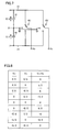
FIG. 7 is an equivalent circuit diagram of a U-phase arm 4U and a V-phase arm 4V of inverter 4 shown in FIG. 2.
FIG. 8 is a diagram showing a line voltage of a single-phase, three-level inverter shown in FIG. 7.
FIG. 9 is a diagram showing a result of simulation of a reactor current in an example where a filter reactor provided on an output side of a two-level inverter is set to 5% and the inverter is switched at a frequency of 10 kHz.
FIG. 10 is a diagram showing a result of simulation of a reactor current in an example where a filter reactor provided on an output side of a two-level inverter is set to 10% and the inverter is switched at a frequency of 10 kHz.
FIG. 11 is a diagram showing a result of simulation of a reactor current in an example where a filter reactor provided on an output side of a three-level inverter is set to 5% and the inverter is switched at a frequency of 10 kHz.
FIG. 12 is a diagram showing a frequency spectrum of a harmonic current (FIG. 9) generated by the two-level inverter.
FIG. 13 is a diagram showing a frequency spectrum of a harmonic current (FIG. 11) generated by the three-level inverter.
FIG. 14 is a diagram showing a result of simulation of fluctuation of a potential to ground of the two-level inverter and fluctuation of a potential to ground of the three-level inverter.
FIG. 15 is a diagram showing a result of simulation of loss in the two-level inverter and the three-level inverter.
FIG. 16 is a diagram illustrating a breakdown of the loss in the two-level inverter and the three-level inverter.
FIG. 17 is a diagram showing a configuration of a semiconductor switch included in a conventional DC voltage converter.
FIG. 18 is a diagram showing a switching pattern of IGBT elements Q1D to Q4D in FIG. 3 and a voltage applied to a reactor 22.
FIG. 19 is a diagram showing a state that a power conversion apparatus according to the present invention is applied to a three-phase, four-wire system.
DESCRIPTION OF THE REFERENCE SIGNS
1 commercial AC power supply; 2 input filter; 3 converter; 3R R-phase arm; 3S S-phase arm; 3T T-phase arm; 4, 41 inverter; 4U, 41U U-phase arm; 4V, 41V V-phase arm; 4W W-phase arm; 5 output filter; 6 load; 7 DC voltage converter; 8 storage battery; 10 control device; 11, 11R, 11S, 11T, 15, 16, 19, 19U, 19V, 19W capacitor; 12, 12R, 12S, 12T, 18, 18U, 18V, 18W reactor; 13, 42 DC positive bus; 14, 43 DC negative bus; 17 DC neutral point bus; 21, O neutral point; 22, 22N, 22P, 45 reactor; 23, 44 semiconductor switch; 31, 36 voltage sensor; 32, 37 current sensor; 33 power failure detection circuit; 100 uninterruptible power supply system; CA, CB, CC, CD capacitor; D1D to D4D, D1R to D6R, D1S to D6S, D1T to D6T, D1U to D6U, D1V to D6V, D1W to D6W, DA, DB, DC, DD diode; Q1D to Q4D, Q1R to Q4R, Q1S to Q4S, Q1T to Q4T, Q1U to Q4U, Q1V to Q4V, Q1W to Q4W, QA, QB, QC, QD IGBT element; RL R-phase line; SL S-phase line; TL T-phase line; UL U-phase line; VL V-phase line; and WL W-phase line.
BEST MODES FOR CARRYING OUT THE INVENTION
An embodiment of the present invention will be described hereinafter in detail with reference to the drawings. It is noted that the same or corresponding elements in the drawings have the same reference characters allotted and description thereof will not be repeated.
FIG. 1 is a schematic block diagram showing a main circuit configuration of an uninterruptible power supply system 100 according to an embodiment of the present invention. Referring to FIG. 1, uninterruptible power supply system 100 includes an input filter 2, a converter 3, an inverter 4, an output filter 5, a DC voltage converter (denoted as “DC/DC” in the drawing) 7, a control device 10, a DC positive bus 13, a DC negative bus 14, capacitors 15 and 16, a DC neutral point bus 17, voltage sensors 31 and 36, current sensors 32 and 37, a power failure detection circuit 33, an R-phase line RL, an S-phase line SL, and a T-phase line TL.
Input filter 2 prevents leakage of harmonics to commercial AC power supply 1. Commercial AC power supply 1 is a three-phase AC power supply. Input filter 2 is a three-phase LC filter circuit constituted of a capacitor 11 ( capacitors 11R, 115 and 11T) and a reactor 12 ( reactors 12R, 12S and 12T).
Converter 3 converts three-phase AC power supplied from commercial AC power supply 1 through input filter 2 into DC power and supplies the DC power to inverter 4 through DC positive bus 13 and DC negative bus 14. Inverter 4 converts the DC power from converter 3 into three-phase AC power. As will be described later, converter 3 and inverter 4 are each implemented by a three-level circuit. Converter 3 and inverter 4 are connected to each other through DC positive bus 13, DC negative bus 14 and DC neutral point bus 17.
Capacitors 15 and 16 are connected in series between DC positive bus 13 and DC negative bus 14 and they smoothen a voltage across DC positive bus 13 and DC negative bus 14. DC neutral point bus 17 is connected to a neutral point 21 which is a point of connection between capacitors 15 and 16.
The AC power from inverter 4 is supplied to a load 6 through output filter 5. Output filter 5 removes harmonics generated by an operation of inverter 4. Output filter 5 is a three-phase LC filter circuit constituted of a reactor 18 ( reactors 18U, 18V and 18W) and a capacitor 19 ( capacitors 19U, 19V and 19W).
DC voltage converter 7 carries out conversion between a DC voltage across DC positive bus 13 and DC negative bus 14 and a voltage of a storage battery 8. It is noted that a power storage device that can be charged and can discharge should only be connected to DC voltage converter 7, and for example, an electric double layer capacitor may be connected to DC voltage converter 7. In addition, though storage battery 8 is installed outside uninterruptible power supply system 100 in the present embodiment, storage battery 8 may be contained in uninterruptible power supply system 100.
Voltage sensor 31 detects a voltage VR of the R-phase line, a voltage VS of the S-phase line, and a voltage VT of the T-phase line, and outputs three-phase voltage signals indicating respective voltages VR, VS and VT to control device 10 and power failure detection circuit 33. Current sensor 32 detects a current IR of the R-phase line, a current IS of the S-phase line, and a current IT of the T-phase line and outputs three-phase current signals indicating respective voltages IR, IS and IT to control device 10.
Power failure detection circuit 33 detects power failure of commercial AC power supply 1 based on the three-phase voltage signal from voltage sensor 31. Power failure detection circuit 33 outputs a power failure signal indicating power failure of commercial AC power supply 1 to control device 10. Voltage sensor 36 detects a voltage VB across positive and negative electrodes of storage battery 8 and outputs a signal indicating voltage VB to control device 10. Current sensor 37 detects a current IB input and output to/from storage battery 8 and outputs a signal indicating current IB to control device 10.
Control device 10 controls operations of converter 3, inverter 4 and DC voltage converter 7. Though detailed description will be provided later, each of converter 3, inverter 4 and DC voltage converter 7 is implemented by a semiconductor switch including a semiconductor switching element. In the present embodiment, an IGBT (Insulated Gate Bipolar Transistor) is employed as the semiconductor switching element. In addition, in the present embodiment, PWM (Pulse Width Modulation) control is applicable as a method of controlling the semiconductor switching element. Control device 10 carries out PWM control, upon receiving the three-phase voltage signal from voltage sensor 31, the three-phase current signal from current sensor 32, the power failure signal from power failure detection circuit 33, the signal indicating voltage VB detected by voltage sensor 36, the signal indicating current IB detected by current sensor 37, and the like.
An operation of uninterruptible power supply system 100 according to the present embodiment will now be described. While commercial AC power supply 1 can normally supply AC power, converter 3 converts AC power from commercial AC power supply 1 to DC power and inverter 4 converts the DC power into AC power and supplies the AC power to load 6. DC voltage converter 7 converts the DC voltage from converter 3 into a voltage suitable for charging storage battery 8, so that storage battery 8 is charged. On the other hand, when the commercial AC power supply fails, control device 10 stops converter 3 based on the power failure signal from power failure detection circuit 33. In addition, control device 10 operates DC voltage converter 7 such that DC power is supplied from storage battery 8 to inverter 4, thus causing inverter 4 to continue supply of AC power. Here, DC voltage converter 7 converts the voltage of storage battery 8 into a voltage suitable as an input voltage for inverter 4. Thus, AC power can be supplied to an AC load in a stable manner.
FIG. 2 is a circuit diagram illustrating in detail a configuration of converter 3 and inverter 4 shown in FIG. 1. Referring to FIG. 2, converter 3 includes an R-phase arm 3R, an S-phase arm 3S and a T-phase arm 3T. Inverter 4 includes a U-phase arm 4U, a V-phase arm 4V and a W-phase arm 4W.
The arm of each phase (3R, 3S, 3T) of converter 3 and the arm of each phase (4U, 4V, 4W) of inverter 4 are each implemented by a three-level circuit, and each of them includes four IGBT elements and six diodes. Specifically, R-phase arm 3R includes IGBT elements Q1R to Q4R and diodes D1R to D6R. S-phase arm 3S includes IGBT elements Q1S to Q4S and diodes D1S to D6S. T-phase arm 3T includes IGBT elements Q1T to Q4T and diodes D1T to D6T. U-phase arm 4U includes IGBT elements Q1U to Q4U and diodes D1U to D6U. V-phase arm 4V includes IGBT elements Q1V to Q4V and diodes D1V to D6V. W-phase arm 4W includes IGBT elements Q1W to Q4W and diodes D1W to D6W.
Hereinafter, in order to collectively describe the arm of each phase of converter 3 and the arm of each phase of inverter 4, reference characters R, S, T, U, V, and W are collectively denoted as a reference character “x”. IGBT elements Q1 x to Q4 x are connected in series between DC positive bus 13 and DC negative bus 14. Diodes D1 x to D4 x are connected in anti-parallel to IGBT elements Q1 x to Q4 x respectively. Diode D5 x is connected to a point of connection between IGBT elements Q1 x and Q2 x and neutral point 21. Diode D6 x is connected to a point of connection between IGBT elements Q3 x and Q4 x and neutral point 21. It is noted that diode D5 x has a cathode connected to the point of connection between IGBT elements Q1 x and Q2 x and has an anode connected to neutral point 21. Diode D6 x has an anode connected to the point of connection between IGBT elements Q3 x and Q4 x and has a cathode connected to neutral point 21. Diodes D1 x to D4 x function as free-wheeling diodes, and diodes D5 x and D6 x function as clamp diodes.
In the arm of each phase (3R, 3S, 3T) of converter 3, a point of connection between IGBT elements Q2 x and Q3 x corresponds to an AC input terminal, and a point of connection between diodes D5 x and D6 x corresponds to a DC output terminal. Meanwhile, in the arm of each phase (4U, 4V, 4T) of inverter 4, the point of connection between diodes D5 x and D6 x corresponds to a DC input terminal, and the point of connection between IGBT elements Q2 x and Q3 x corresponds to an AC output terminal. The AC input terminal of the arm of each phase (3R, 3S, 3T) of converter 3 is connected to a corresponding line (R-phase line RL, S-phase line SL, T-phase line TL), and the AC output terminal of the arm of each phase (4U, 4V, 4S) of inverter 4 is connected to a corresponding line (U-phase line UL, V-phase line VL, W-phase line WL). The DC output terminal of the arm of each phase of converter 3 and the DC input terminal of the arm of each phase of inverter 4 are connected to neutral point 21.
FIG. 3 is a diagram illustrating in detail a configuration of DC voltage converter 7 shown in FIG. 1. Referring to FIG. 3, DC voltage converter 7 includes a reactor 22 and a semiconductor switch 23. Semiconductor switch 23 includes IGBT elements Q1D to Q4D connected in series between DC positive bus 13 and DC negative bus 14 and diodes D1D to D4D connected in anti-parallel to IGBT elements Q1D to Q4D respectively.
In semiconductor switch 23, one end of a reactor 22P is connected to a point of connection between IGBT elements Q1D and Q2D and one end of a reactor 22N is connected to a point of connection between IGBT elements Q3D and Q4D. The other end of reactor 22P is connected to the positive electrode of storage battery 8 and the other end of reactor 22N is connected to the negative electrode of storage battery 8.
As described above, in uninterruptible power supply system 100 according to the present embodiment, converter 3 and inverter 4 are each implemented by a three-level circuit. In the conventional power conversion apparatus, for the purpose of decrease or the like in the number of semiconductor switching elements, an inverter is generally implemented by a two-level circuit. By implementing the inverter with a three-level circuit, harmonics can be suppressed more than in the conventional power conversion apparatus.
FIG. 4 is a diagram showing a single-phase inverter implemented by a two-level circuit. Referring to FIG. 4, an inverter 41 includes a U-phase arm 41U and a V-phase arm 41V. U-phase arm 41U and V-phase arm 41V are connected in parallel between a DC positive bus 42 and a DC negative bus 43 and they are identical in configuration. U-phase arm 41U includes IGBT elements QA and QB connected in series between DC positive bus 42 and DC negative bus 43 and diodes DA and DB connected in anti-parallel to IGBT elements QA and QB respectively. U-phase line UL is connected to a point of connection between IGBT elements QA and QB. V-phase arm 41V has such a configuration that U-phase line UL in the configuration of U-phase arm 41U above is replaced with V-phase line VL.
Capacitors CA and CB are connected in series between DC positive bus 42 and DC negative bus 43. A neutral point O is a point of connection between capacitors CA and CB. A voltage across opposing ends of capacitor CA and a voltage across opposing ends of capacitor CB are both E/2 (E being a prescribed value).
FIG. 5 is an equivalent circuit of inverter 41 shown in FIG. 4. Referring to FIG. 5, U-phase arm 41U is equivalent to a switch that switches connection of U-phase line UL between DC positive bus 42 and DC negative bus 43. Considering an example where neutral point O is grounded, when the switch operates, a voltage Vu of U-phase line UL switches between E/2 and −E/2. A voltage Vv of V-phase line VL varies similarly to voltage Vu. Thus, the two-level circuit converts a DC voltage E to an AC voltage having two values (E/2, −E/2).
FIG. 6 is a diagram showing a line voltage of inverter 41. Referring to FIG. 6, a line voltage (a difference between voltage Vu and voltage Vv) switches between E, 0, and −E. In an inverter implemented by a two-level circuit (a two-level inverter), a minimum variation of the line voltage is equal to voltage E.
FIG. 7 is an equivalent circuit diagram of U-phase arm 4U and V-phase arm 4V of inverter 4 shown in FIG. 2. Referring to FIG. 7, U-phase arm 4U is equivalent to a switch that switches connection of U-phase line UL between DC positive bus 13, neutral point 21, and DC negative bus 14. When this switch operates, voltage Vu of U-phase line UL switches between E/2, 0 and −E/2. Voltage Vv of V-phase line VL also varies similarly to voltage Vu. Thus, the three-level circuit is a circuit capable of performing conversion between a DC voltage and an AC voltage having three values.
FIG. 8 is a diagram showing a line voltage of a single-phase, three-level inverter shown in FIG. 7. Referring to FIG. 7, the line voltage (a difference between voltage Vu and voltage Vv) switches in a range of E, E/2, 0, −E/2, and −E. In an inverter implemented by a three-level circuit (a three-level inverter), a minimum variation of the line voltage is equal to E/2.
It can be seen from FIGS. 6 and 8 that the three-level inverter is smaller in variation of the line voltage than the two-level inverter. Since a waveform of an output voltage of the inverter finely varies as the variation of the line voltage is smaller, the waveform can be closer to a sinusoidal wave. As the voltage waveform is closer to the sinusoidal wave, harmonics generated by the operation of the inverter can be made smaller. Therefore, harmonics can be made smaller by the three-level inverter than the two-level inverter.
FIG. 9 is a diagram showing a result of simulation of a reactor current in an example where a filter reactor provided on an output side of a two-level inverter is set to 5% and the inverter is switched at a frequency of 10 kHz. FIG. 10 is a diagram showing a result of simulation of a reactor current in an example where a filter reactor provided on an output side of a two-level inverter is set to 10% and the inverter is switched at a frequency of 10 kHz. Comparing total harmonic distortion (THD) based on simulation in FIGS. 9 and 10, THD is 6.4% when reactor inductance is set to 5%, whereas THD decreases to 3.2% by increasing reactor inductance to 10%.
THD represents a ratio between the sum of effective values of harmonic components and effective values of fundamental waves. Smaller THD means smaller harmonic components. FIGS. 9 and 10 show that THD decreases by increasing reactor inductance. If reactor inductance is increased in order to make the harmonic components smaller, it is necessary, for example, to increase the number of turns of a coil, and a problem of increase in volume and weight of the reactor arises.
FIG. 11 is a diagram showing a result of simulation of a reactor current in an example where a filter reactor provided on an output side of a three-level inverter is set to 5% and the inverter is switched at a frequency of 10 kHz. Referring to FIGS. 11 and 9, it can be seen that the three-level inverter can suppress harmonic components more than the two-level inverter provided that filter reactors are identical in inductance. In the simulation result shown in FIG. 11, THD was 3.2%.
FIG. 12 is a diagram showing a frequency spectrum of a harmonic current (FIG. 9) generated by the two-level inverter. FIG. 13 is a diagram showing a frequency spectrum of a harmonic current (FIG. 11) generated by the three-level inverter. Referring to FIGS. 12 and 13, it can be seen that the three-level inverter can suppress harmonics more than the two-level inverter, regardless of a frequency. It is noted that frequency spectra in FIGS. 12 and 13 could be obtained by simulation. In simulation, a DC voltage input to the inverter was set to 500 V, a three-phase resistance load of 10 kW was adopted as a load, and an output voltage (line voltage) was set to 208 Vrms.
Thus, according to the present embodiment, by implementing an inverter with a three-level circuit, harmonics generated by the inverter can be made smaller. As a reactor having small inductance can thus be used for the filter, the reactor can have smaller volume and weight. Therefore, according to the present embodiment, reduction in size and lighter weight of the power conversion apparatus can be achieved.
In the present embodiment, the following effects can also be obtained by implementing an inverter with a three-level circuit. In the power conversion apparatus, a storage battery or the like having large capacity is connected, as a DC power supply, to a DC capacitor on the input side of the inverter. When fluctuation of a potential to ground becomes greater during operation of the inverter, an amount of generated noise increases due to a large stray capacitance of a DC circuit. Since variation of the output voltage becomes greater by implementing inverter 4 with a two-level inverter, fluctuation of a potential to ground also becomes greater. In the present embodiment, however, by implementing inverter 4 with a three-level inverter, variation of the output voltage thereof can be made smaller than in a case of a two-level inverter. As fluctuation of a potential to ground can thus be made smaller, an amount of generated noise can be decreased.
FIG. 14 is a diagram showing a result of simulation of fluctuation of a potential to ground of the two-level inverter and fluctuation of a potential to ground of the three-level inverter. In simulation, a DC voltage input to the inverter was set to 360 V. Referring to FIG. 14, assuming fluctuation of a potential to ground in the two-level inverter as 1 [p.u], fluctuation of a potential to ground in the three-level inverter is 0.5 [p.u]. As shown in FIG. 14, the three-level inverter can achieve smaller fluctuation of a potential to ground.
In addition, according to the present embodiment, loss in inverter 4 can be decreased. Loss in inverter 4 specifically refers to conduction loss (loss in each of the IGBT element and the diode when they are fed with power) and switching loss in the IGBT element.
FIG. 15 is a diagram showing a result of simulation of loss in the two-level inverter and the three-level inverter. FIG. 16 is a diagram illustrating a breakdown of the loss in the two-level inverter and the three-level inverter. In this simulation, a DC input voltage was set to 600 V, a switching frequency was set to 10 kHz, an AC output voltage (line voltage) was set to 380 Vrms, and magnitude of a load was set to 275 kW. It is noted that the IGBT element included in the two-level inverter is a 1200V-600 A product and the IGBT element included in the three-level inverter is a 600V-600 A product.
Referring to FIGS. 15 and 16, the entire loss in the three-level inverter is equal to 83% of the entire loss in the two-level inverter, because switching loss is decreased. As shown in FIG. 15, the three-level inverter is smaller in switching loss than the two-level inverter (33%), because a voltage applied to a single semiconductor switching element can be lowered in the three-level inverter as compared with the two-level inverter.
As shown in FIG. 16, in the two-level inverter, switching loss occupies most (63%) of the entire loss. The three-level inverter can achieve significant decrease in the switching loss. Therefore, in the three-level inverter, though conduction loss increases as compared with the two-level inverter, the entire loss can be smaller than in the two-level inverter. By decreasing loss in the inverter, operation efficiency of the power conversion apparatus can be enhanced.
In the present embodiment, since converter 3 is also implemented by a three-level circuit, an effect the same as in inverter 4 can also be achieved by converter 3. Specifically, a reactor included in an input filter can be reduced in size. Thus, reduction in size and lighter weight of the power conversion apparatus can further be achieved. In addition, since fluctuation of a potential to ground can be suppressed, an amount of noise generated by converter 3 can also be lowered. Moreover, since loss in converter 3 can be decreased, operation efficiency of the power conversion apparatus can be enhanced. In addition to these effects, since common components can be used in converter 3 and inverter 4, cost for the power conversion apparatus can be reduced.
Further, DC voltage converter 7 has conventionally had such a configuration that two IGBT elements QC and QD are connected in series as shown in a semiconductor switch 44 in FIG. 17. As shown in FIG. 3, in the present embodiment, ripple components in a current that flows through reactor 22 are decreased by implementing a semiconductor switch by connecting four IGBT elements in series. In the case of the configuration in FIG. 17, when IGBT element QC is ON and IGBT element QD is OFF, a voltage of (E−VB) is applied to a reactor 45, and when IGBT element QC is OFF and IGBT element QD is ON, a voltage of (−VB) is applied to reactor 45. Therefore, a reactor voltage difference produced by switching is E. In contrast, in the configuration in FIG. 3, when only IGBT elements Q2D and Q3D are turned ON, a voltage of (−VB) is applied to reactor 22, and when only IGBT elements Q1D and Q4D are turned ON, a voltage of (E−VB) is applied to reactor 22. Other than these examples, there is an example where only IGBT elements Q1D and Q3D are turned ON or an example where only IGBT elements Q2D and Q4D are turned ON, and in such a case, a voltage of E/2−VB is applied to reactor 22.
FIG. 18 shows a switching pattern of IGBT elements Q1D to Q4D and a voltage applied to reactor 22. It can be seen from FIG. 18 that a voltage that can be applied to reactor 22 by DC voltage converter 7 also has three levels. According to the configuration in FIG. 3, the reactor voltage difference produced by switching can be set to E/2 and ripple components in a current that flows through reactor 22 can be decreased. Thus, inductance of reactor 22 can be decreased and reactor 22 can be reduced in size, and therefore reduction in size and lighter weight of the power conversion apparatus can further be achieved.
In the present embodiment, a three-level circuit has been shown, however, a circuit implementing an inverter, a converter or a DC voltage converter should only be a circuit (a multi-level circuit) that performs conversion between a DC voltage and an AC voltage or a DC voltage having at least three voltage values. Therefore, a five-level circuit for performing conversion between a DC voltage and an AC voltage having at least five voltage values is applicable to an inverter or the like.
In addition, in the present embodiment, an uninterruptible power supply system applicable to a three-phase, three-wire system AC power supply and load has been shown, however, the present invention is also applicable to a three-phase, four-wire system AC power supply and load. In the case of the three-phase, four-wire system, as shown in FIG. 19, it is only necessary to connect neutral points of respective capacitors 11 and 19 to neutral point 21. Further, the AC power supply and the AC load are not limited to those of three phases, and a single-phase power supply or load may be adopted. In that case, two multi-level circuits should only be included in each of a converter and an inverter.
In addition, in the present embodiment, a DC voltage converter is applied between the storage battery and the DC bus, however, the DC voltage converter can naturally be eliminated so long as the storage battery within a rated operation range of the DC bus can be selected.
Moreover, in the present embodiment, an example where the power conversion apparatus according to the present invention is applied to the uninterruptible power supply system including the storage battery has been described, however, a filter achieving smaller size and lighter weight that includes a multi-level circuit as well as achieving suppression of fluctuation of a potential to ground is applicable to a power conversion apparatus outputting AC power based on DC power, such as a solar power generation system, a fuel cell power generation system, or a secondary battery energy storage system.
It should be understood that the embodiments disclosed herein are illustrative and non-restrictive in every respect. The scope of the present invention is defined by the terms of the claims, rather than the description above, and is intended to include any modifications within the scope and meaning equivalent to the terms of the claims.

Claims (5)

The invention claimed is:
1. A power conversion apparatus, comprising:
a first conversion device including a first multi-level circuit configured to be able to perform conversion between a DC voltage and an AC voltage varying among at least three voltage values, for converting DC power to AC power for supply to a load;
a second conversion device for converting AC power from an AC power supply to DC power for supply to said first conversion device;
a DC positive bus and a DC negative bus;
first and second capacitors connected in series between said DC positive bus and said DC negative bus;
a third conversion device for converting a voltage value of power stored in a power storage device and supplying DC power from said power storage device to said first conversion device when power supply by said AC power supply is faulty; and
a filter including a reactor and a capacitor, for removing a harmonic generated by said first conversion device, wherein
said third conversion device includes a third multi-level circuit configured to be able to perform conversion between a DC voltage and a DC voltage varying among at least three voltage values, and
said third multi-level circuit includes
a first, second, third and fourth semiconductor switching element connected in series,
a first reactor connected between a point of connection of the first and second semiconductor switching elements and a positive electrode of the power storage device,
a second reactor connected between a point of connection of the third and fourth semiconductor switching elements and a negative electrode of said power storage device,
wherein the first and second capacitors are connected between a point of connection of the second and third semiconductor switching elements.
2. The power conversion apparatus according to claim 1, wherein said second conversion device includes a second multi-level circuit identical in configuration to said first multi-level circuit.
3. The power conversion apparatus according to claim 1, wherein
the DC positive bus and the DC negative bus are configured to transmit DC power from said second conversion device or said third conversion device or DC power from said second conversion device and said third conversion device to said first conversion device, and
said first multi-level circuit includes
first to fourth semiconductor switching elements connected in series between said DC positive bus and said DC negative bus,
first to fourth free-wheeling diodes connected in anti-parallel to said first to fourth semiconductor switching elements respectively,
a first clamp diode connected between a neutral point of said first and second capacitors and a point of connection between said first and second semiconductor switching elements, and
a second clamp diode connected between said neutral point and a point of connection between said third and fourth semiconductor switching elements.
4. The power conversion apparatus according to claim 1, wherein the filter includes a reactor and a capacitor.
5. The power conversion apparatus according to claim 1, wherein the first and second capacitors are directly connected to the point of connection of the second and third semiconductor switching elements.
US13/055,373 2008-07-30 2008-07-30 Power conversion apparatus Active 2030-07-02 US8994216B2 (en)

Applications Claiming Priority (1)

Application Number Priority Date Filing Date Title
PCT/JP2008/063664 WO2010013322A1 (en) 2008-07-30 2008-07-30 Power conversion device

Publications (2)

Publication Number Publication Date
US20110127837A1 US20110127837A1 (en) 2011-06-02
US8994216B2 true US8994216B2 (en) 2015-03-31

Family

ID=41610046

Family Applications (1)

Application Number Title Priority Date Filing Date
US13/055,373 Active 2030-07-02 US8994216B2 (en) 2008-07-30 2008-07-30 Power conversion apparatus

Country Status (7)

Country Link
US (1) US8994216B2 (en)
JP (1) JP5248611B2 (en)
KR (1) KR101189428B1 (en)
CN (1) CN102124625B (en)
CA (1) CA2732316C (en)
MX (1) MX2011000429A (en)
WO (1) WO2010013322A1 (en)

Cited By (4)

* Cited by examiner, † Cited by third party
Publication number Priority date Publication date Assignee Title
US20150042169A1 (en) * 2013-08-07 2015-02-12 Samsung Electronics Co., Ltd. Wireless power transmission method and apparatus for stably transmitting power to plurality of wireless power reception apparatuses
RU2668416C1 (en) * 2017-04-06 2018-10-01 Федеральное государственное унитарное предприятие "Крыловский государственный научный центр" Three-level frequency converter
RU2682164C1 (en) * 2018-04-02 2019-03-15 Федеральное государственное бюджетное образовательное учреждение высшего образования "Магнитогорский государственный технический университет им. Г.И. Носова" High-voltage frequency converter control device
US11228258B2 (en) * 2018-11-20 2022-01-18 Toshiba Mitsubishi-Electric Industrial Systems Corporation Uninterruptible power supply apparatus

Families Citing this family (29)

* Cited by examiner, † Cited by third party
Publication number Priority date Publication date Assignee Title
CN102549879B (en) 2009-09-25 2014-09-03 东芝三菱电机产业系统株式会社 Uninterruptible power-supply system
WO2011039865A1 (en) 2009-09-30 2011-04-07 東芝三菱電機産業システム株式会社 Power conversion system
JP5386640B2 (en) * 2010-08-23 2014-01-15 東芝三菱電機産業システム株式会社 Power converter
KR101452146B1 (en) 2011-01-07 2014-10-16 도시바 미쓰비시덴키 산교시스템 가부시키가이샤 Electric power converter
EP2512000B1 (en) 2011-04-15 2022-03-02 ABB Schweiz AG Reconfigurable power systems and converters
CN102832796A (en) * 2011-06-15 2012-12-19 力博特公司 Buffer circuit and inverter with same
AU2012340729B2 (en) 2011-11-21 2017-04-06 Zinniatek Limited Single phase inverters cooperatively controlled to provide one, two, or three phase unipolar electricity
CN103138595B (en) * 2011-11-22 2016-05-25 通用电气公司 The control system of neutral point clamped multi current transformer and control method
DE112012005842T5 (en) * 2012-02-08 2014-11-06 Mitsubishi Electric Corporation Energy conversion device
KR102085816B1 (en) * 2013-07-02 2020-03-06 엘지이노텍 주식회사 Power conditioning system and Energy storage system
KR102068177B1 (en) * 2013-09-11 2020-01-20 엘지전자 주식회사 Energy storage device, and system for supplying power including the same
CN105830331B (en) * 2013-12-18 2019-08-27 奥的斯电梯公司 Bus capacitor group for more levels of regenerative drivers configures
US9590521B2 (en) * 2014-07-28 2017-03-07 Hamilton Sundstrand Corporation Power converters for aircraft starter/generators
KR102270104B1 (en) * 2014-08-14 2021-06-25 엘지전자 주식회사 Energy storage device and energy storage system including the same
CN109075718B (en) * 2016-02-05 2021-12-17 Abb瑞士股份有限公司 Power conditioning and UPS module
US10574086B2 (en) * 2016-04-08 2020-02-25 Rhombus Energy Solutions, Inc. Nonlinear control algorithm and system for a single-phase AC-AC converter with bidirectional isolated DC-DC converter
CN109874377B (en) * 2016-09-22 2022-10-28 索尤若驱动有限及两合公司 System and method for operating a system
US10734903B2 (en) * 2017-04-25 2020-08-04 Toshiba Mitsubishi-Electric Industrial Systems Corporation Power supply apparatus
CN107863893A (en) * 2017-12-14 2018-03-30 中机国际工程设计研究院有限责任公司 The level rectifying system of midpoint self-balancing three
US11424693B2 (en) * 2018-04-27 2022-08-23 Toshiba Mitsubishi-Electric Industrial Systems Corporation Three-level power conversion device, three-level power conversion device control method, and storage medium
CN108696149A (en) * 2018-05-25 2018-10-23 中车青岛四方车辆研究所有限公司 Traction convertor and its control, troubleshooting and phase-shifting carrier wave method
WO2020055511A1 (en) 2018-09-14 2020-03-19 Gopro, Inc. Electrical connectivity between detachable components
US10439512B1 (en) * 2018-09-27 2019-10-08 Schneider Electric It Corporation Clamp circuit to reduce overshoot in power converters
JP6703643B1 (en) * 2018-11-14 2020-06-03 東芝三菱電機産業システム株式会社 Power converter
JP7267287B2 (en) * 2019-06-04 2023-05-01 東芝三菱電機産業システム株式会社 Power conversion device and power conversion control device
JP6771693B1 (en) * 2019-08-30 2020-10-21 三菱電機株式会社 Power converter
US11303149B2 (en) 2020-02-03 2022-04-12 Schneider Electric It Corporation Short-circuit current capacity enhancement
CN114069819A (en) * 2020-08-07 2022-02-18 台达电子工业股份有限公司 Conversion device with three-layer switching circuit and operation method of three-layer switching circuit
CN112152497B (en) * 2020-10-09 2021-07-02 上海海事大学 Fault-tolerant control method of cascaded five-level inverter

Citations (29)

* Cited by examiner, † Cited by third party
Publication number Priority date Publication date Assignee Title
JPS56121374A (en) 1980-02-26 1981-09-24 Toshiba Corp Inverter device
JPH0833233A (en) 1994-07-15 1996-02-02 Sanyo Denki Co Ltd Ac/dc uninterruptible power supply
US5638266A (en) * 1994-03-10 1997-06-10 Hitachi, Ltd. Free wheel diode arrangement for neutral point clamped electric power conversion apparatus
US5892674A (en) * 1996-02-16 1999-04-06 Hitachi, Ltd. Method and apparatus for power converting AC into DC or DC into AC by converter having common phase connection
WO1999060690A1 (en) 1998-05-21 1999-11-25 Powerware Corporation Systems and methods for producing standby uninterruptible power for ac loads using rectified ac and battery
CA2314782A1 (en) 1999-08-13 2001-02-13 Powerware Corporation Multi-mode power converters incorporating balancer circuits and methods of operation thereof
JP2002247862A (en) 2001-02-20 2002-08-30 Hitachi Ltd Power converter
JP2002369542A (en) 2001-06-12 2002-12-20 Mitsubishi Electric Corp Semiconductor power module and power converter
JP2003299365A (en) 2002-04-01 2003-10-17 Fuji Electric Co Ltd Inverter circuit
JP2004248479A (en) 2003-02-17 2004-09-02 Toshiba Corp Three-level converter
JP2004350471A (en) 2003-05-26 2004-12-09 Hitachi Medical Corp Voltage divider circuit
CN1635695A (en) 2003-12-26 2005-07-06 台达电子工业股份有限公司 DC/DC converter having voltage clamping circuit
JP2005333775A (en) 2004-05-21 2005-12-02 Sanken Electric Co Ltd Ac power supply
JP2006109603A (en) 2004-10-05 2006-04-20 Densei Lambda Kk Uninterruptible power supply device, control method therefor, uninterruptible power supply system, and uninterruptible power supply program
JP2006141165A (en) 2004-11-15 2006-06-01 Fuji Electric Systems Co Ltd Uninterruptible power supply device
JP2006238514A (en) 2005-02-22 2006-09-07 Hitachi Ltd Uninterruptible power supply device
JP2006345647A (en) 2005-06-09 2006-12-21 Fuji Electric Systems Co Ltd Uninterruptible power supply
JP2007028860A (en) 2005-07-21 2007-02-01 Hitachi Ltd Power-converting device and rolling stock equipped with the same
JP2007089301A (en) 2005-09-21 2007-04-05 Nec Fielding Ltd Uninterruptible power supply system and output control method thereof
CN2901688Y (en) 2006-05-25 2007-05-16 山东新风光电子科技发展有限公司 Contravariant circuit of current source
JP2007151231A (en) 2005-11-24 2007-06-14 Toshiba Mitsubishi-Electric Industrial System Corp Uninterruptible power unit
JP2007215378A (en) 2006-02-13 2007-08-23 Fuji Electric Systems Co Ltd Uninterruptible power unit
JP2007215344A (en) 2006-02-10 2007-08-23 Meidensha Corp Uninterruptible power supply system
JP2007300712A (en) 2006-04-28 2007-11-15 Sanken Electric Co Ltd Ac power feeding device
JP2008022625A (en) 2006-07-12 2008-01-31 Fuji Electric Systems Co Ltd Ac-dc converter
JP2008141850A (en) 2006-11-30 2008-06-19 Hitachi Ltd Uninterruptible power supply system, inverter circuit, and reactor panel
JP2008193779A (en) 2007-02-02 2008-08-21 Fuji Electric Systems Co Ltd Semiconductor module
US20080238383A1 (en) * 2007-03-19 2008-10-02 Honda Motor Co., Ltd. Power converter and multiport power converter
US20090284200A1 (en) 2008-05-13 2009-11-19 Fuji Electric Device Technology Co., Ltd. AC motor driving circuit and electric vehicle driving circuit

Patent Citations (32)

* Cited by examiner, † Cited by third party
Publication number Priority date Publication date Assignee Title
JPS56121374A (en) 1980-02-26 1981-09-24 Toshiba Corp Inverter device
US5638266A (en) * 1994-03-10 1997-06-10 Hitachi, Ltd. Free wheel diode arrangement for neutral point clamped electric power conversion apparatus
JPH0833233A (en) 1994-07-15 1996-02-02 Sanyo Denki Co Ltd Ac/dc uninterruptible power supply
US5892674A (en) * 1996-02-16 1999-04-06 Hitachi, Ltd. Method and apparatus for power converting AC into DC or DC into AC by converter having common phase connection
WO1999060690A1 (en) 1998-05-21 1999-11-25 Powerware Corporation Systems and methods for producing standby uninterruptible power for ac loads using rectified ac and battery
JP2002516558A (en) 1998-05-21 2002-06-04 パワーウェア・コーポレーション System and method for generating standby uninterruptible power for an AC load using rectified AC and storage batteries
CA2314782A1 (en) 1999-08-13 2001-02-13 Powerware Corporation Multi-mode power converters incorporating balancer circuits and methods of operation thereof
JP2002247862A (en) 2001-02-20 2002-08-30 Hitachi Ltd Power converter
JP2002369542A (en) 2001-06-12 2002-12-20 Mitsubishi Electric Corp Semiconductor power module and power converter
JP2003299365A (en) 2002-04-01 2003-10-17 Fuji Electric Co Ltd Inverter circuit
JP2004248479A (en) 2003-02-17 2004-09-02 Toshiba Corp Three-level converter
JP2004350471A (en) 2003-05-26 2004-12-09 Hitachi Medical Corp Voltage divider circuit
CN1635695A (en) 2003-12-26 2005-07-06 台达电子工业股份有限公司 DC/DC converter having voltage clamping circuit
JP2005333775A (en) 2004-05-21 2005-12-02 Sanken Electric Co Ltd Ac power supply
JP2006109603A (en) 2004-10-05 2006-04-20 Densei Lambda Kk Uninterruptible power supply device, control method therefor, uninterruptible power supply system, and uninterruptible power supply program
JP2006141165A (en) 2004-11-15 2006-06-01 Fuji Electric Systems Co Ltd Uninterruptible power supply device
JP2006238514A (en) 2005-02-22 2006-09-07 Hitachi Ltd Uninterruptible power supply device
JP2006345647A (en) 2005-06-09 2006-12-21 Fuji Electric Systems Co Ltd Uninterruptible power supply
JP2007028860A (en) 2005-07-21 2007-02-01 Hitachi Ltd Power-converting device and rolling stock equipped with the same
JP2007089301A (en) 2005-09-21 2007-04-05 Nec Fielding Ltd Uninterruptible power supply system and output control method thereof
JP2007151231A (en) 2005-11-24 2007-06-14 Toshiba Mitsubishi-Electric Industrial System Corp Uninterruptible power unit
JP2007215344A (en) 2006-02-10 2007-08-23 Meidensha Corp Uninterruptible power supply system
JP2007215378A (en) 2006-02-13 2007-08-23 Fuji Electric Systems Co Ltd Uninterruptible power unit
JP2007300712A (en) 2006-04-28 2007-11-15 Sanken Electric Co Ltd Ac power feeding device
CN2901688Y (en) 2006-05-25 2007-05-16 山东新风光电子科技发展有限公司 Contravariant circuit of current source
JP2008022625A (en) 2006-07-12 2008-01-31 Fuji Electric Systems Co Ltd Ac-dc converter
JP2008141850A (en) 2006-11-30 2008-06-19 Hitachi Ltd Uninterruptible power supply system, inverter circuit, and reactor panel
JP2008193779A (en) 2007-02-02 2008-08-21 Fuji Electric Systems Co Ltd Semiconductor module
US20100039843A1 (en) 2007-02-02 2010-02-18 Fuji Electric Systems Co., Ltd Semiconductor module for use in power supply
US20080238383A1 (en) * 2007-03-19 2008-10-02 Honda Motor Co., Ltd. Power converter and multiport power converter
US20090284200A1 (en) 2008-05-13 2009-11-19 Fuji Electric Device Technology Co., Ltd. AC motor driving circuit and electric vehicle driving circuit
JP2009278732A (en) 2008-05-13 2009-11-26 Fuji Electric Device Technology Co Ltd Alternating-current motor drive circuit and electric vehicle drive circuit

Non-Patent Citations (8)

* Cited by examiner, † Cited by third party
Title
Combined Office Action and Search Report issued Jul. 23, 2014 in Chinese Patent Application No. 200880130518.X (with English translation and English translation of Category of Cited Documents).
Combined Office Action and Search Report issued Nov. 14, 2012 in Chinese Application No. 200880130518.X (With English Translation).
International Search Report issued Sep. 2, 2008 in PCT/JP08/63664 filed Jul. 30, 2008.
Office Action issued Jan. 11, 2012 in Korea Application No. 10-2010-7029347 (With English Translation).
U.S. Appl. No. 13/057,102, filed Feb. 1, 2011, Sato, et al.
U.S. Appl. No. 13/498,009, filed Mar. 23, 2012, Sato, et al.
U.S. Appl. No. 13/498,515, filed Mar. 27, 2012, Sato, et al.
U.S. Appl. No. 13/879,937, filed Apr. 17, 2013, Kinoshita.

Cited By (5)

* Cited by examiner, † Cited by third party
Publication number Priority date Publication date Assignee Title
US20150042169A1 (en) * 2013-08-07 2015-02-12 Samsung Electronics Co., Ltd. Wireless power transmission method and apparatus for stably transmitting power to plurality of wireless power reception apparatuses
US9796281B2 (en) * 2013-08-07 2017-10-24 Samsung Electronics Co., Ltd. Wireless power transmission method and apparatus for stably transmitting power to plurality of wireless power reception apparatuses
RU2668416C1 (en) * 2017-04-06 2018-10-01 Федеральное государственное унитарное предприятие "Крыловский государственный научный центр" Three-level frequency converter
RU2682164C1 (en) * 2018-04-02 2019-03-15 Федеральное государственное бюджетное образовательное учреждение высшего образования "Магнитогорский государственный технический университет им. Г.И. Носова" High-voltage frequency converter control device
US11228258B2 (en) * 2018-11-20 2022-01-18 Toshiba Mitsubishi-Electric Industrial Systems Corporation Uninterruptible power supply apparatus

Also Published As

Publication number Publication date
JPWO2010013322A1 (en) 2012-01-05
CN102124625B (en) 2015-11-25
CN102124625A (en) 2011-07-13
KR20110028304A (en) 2011-03-17
WO2010013322A9 (en) 2010-12-02
CA2732316A1 (en) 2010-02-04
MX2011000429A (en) 2011-02-23
US20110127837A1 (en) 2011-06-02
WO2010013322A1 (en) 2010-02-04
JP5248611B2 (en) 2013-07-31
CA2732316C (en) 2015-01-06
KR101189428B1 (en) 2012-10-10

Similar Documents

Publication Publication Date Title
US8994216B2 (en) Power conversion apparatus
US8508957B2 (en) Power conversion device for converting DC power to AC power
US8400792B2 (en) Power conversion apparatus
US10892682B2 (en) Power converter with controllable DC offset
JP6227041B2 (en) Multi-level inverter
US9450502B2 (en) Direct power conversion device and method for controlling direct power conversion device
US20090244936A1 (en) Three-phase inverter
JP4783294B2 (en) Power converter for grid connection
US8207712B2 (en) Arrangement for exchanging power
US11228258B2 (en) Uninterruptible power supply apparatus
WO2010095241A1 (en) Power converter
US8493760B2 (en) Electric circuit for converting direct current into alternating current

Legal Events

Date Code Title Description
AS Assignment

Owner name: TOSHIBA MITSUBISHI-ELECTRIC INDUSTRIAL SYSTEMS COR

Free format text: ASSIGNMENT OF ASSIGNORS INTEREST;ASSIGNORS:SATO, EDUARDO KAZUHIDE;KINOSHITA, MASAHIRO;YAMAMOTO, YUSHIN;AND OTHERS;SIGNING DATES FROM 20101102 TO 20101119;REEL/FRAME:025721/0240

STCF Information on status: patent grant

Free format text: PATENTED CASE

MAFP Maintenance fee payment

Free format text: PAYMENT OF MAINTENANCE FEE, 4TH YEAR, LARGE ENTITY (ORIGINAL EVENT CODE: M1551); ENTITY STATUS OF PATENT OWNER: LARGE ENTITY

Year of fee payment: 4

MAFP Maintenance fee payment

Free format text: PAYMENT OF MAINTENANCE FEE, 8TH YEAR, LARGE ENTITY (ORIGINAL EVENT CODE: M1552); ENTITY STATUS OF PATENT OWNER: LARGE ENTITY

Year of fee payment: 8

AS Assignment

Owner name: TMEIC CORPORATION, JAPAN

Free format text: CHANGE OF NAME;ASSIGNOR:TOSHIBA MITSUBISHI-ELECTRIC INDUSTRIAL SYSTEMS CORPORATION;REEL/FRAME:067244/0359

Effective date: 20240401