US8405341B2 - Synchronous electric motor system - Google Patents
Synchronous electric motor system Download PDFInfo
- Publication number
- US8405341B2 US8405341B2 US12/997,871 US99787110A US8405341B2 US 8405341 B2 US8405341 B2 US 8405341B2 US 99787110 A US99787110 A US 99787110A US 8405341 B2 US8405341 B2 US 8405341B2
- Authority
- US
- United States
- Prior art keywords
- phase
- phase inverter
- power
- stator
- synchronous motor
- Prior art date
- Legal status (The legal status is an assumption and is not a legal conclusion. Google has not performed a legal analysis and makes no representation as to the accuracy of the status listed.)
- Expired - Fee Related, expires
Links
Images


Classifications
-
- H—ELECTRICITY
- H02—GENERATION; CONVERSION OR DISTRIBUTION OF ELECTRIC POWER
- H02P—CONTROL OR REGULATION OF ELECTRIC MOTORS, ELECTRIC GENERATORS OR DYNAMO-ELECTRIC CONVERTERS; CONTROLLING TRANSFORMERS, REACTORS OR CHOKE COILS
- H02P25/00—Arrangements or methods for the control of AC motors characterised by the kind of AC motor or by structural details
- H02P25/16—Arrangements or methods for the control of AC motors characterised by the kind of AC motor or by structural details characterised by the circuit arrangement or by the kind of wiring
- H02P25/22—Multiple windings; Windings for more than three phases
-
- H—ELECTRICITY
- H02—GENERATION; CONVERSION OR DISTRIBUTION OF ELECTRIC POWER
- H02K—DYNAMO-ELECTRIC MACHINES
- H02K11/00—Structural association of dynamo-electric machines with electric components or with devices for shielding, monitoring or protection
- H02K11/30—Structural association with control circuits or drive circuits
- H02K11/33—Drive circuits, e.g. power electronics
-
- H—ELECTRICITY
- H02—GENERATION; CONVERSION OR DISTRIBUTION OF ELECTRIC POWER
- H02K—DYNAMO-ELECTRIC MACHINES
- H02K3/00—Details of windings
- H02K3/04—Windings characterised by the conductor shape, form or construction, e.g. with bar conductors
- H02K3/28—Layout of windings or of connections between windings
-
- H—ELECTRICITY
- H02—GENERATION; CONVERSION OR DISTRIBUTION OF ELECTRIC POWER
- H02P—CONTROL OR REGULATION OF ELECTRIC MOTORS, ELECTRIC GENERATORS OR DYNAMO-ELECTRIC CONVERTERS; CONTROLLING TRANSFORMERS, REACTORS OR CHOKE COILS
- H02P27/00—Arrangements or methods for the control of AC motors characterised by the kind of supply voltage
- H02P27/04—Arrangements or methods for the control of AC motors characterised by the kind of supply voltage using variable-frequency supply voltage, e.g. inverter or converter supply voltage
- H02P27/06—Arrangements or methods for the control of AC motors characterised by the kind of supply voltage using variable-frequency supply voltage, e.g. inverter or converter supply voltage using dc to ac converters or inverters
- H02P27/08—Arrangements or methods for the control of AC motors characterised by the kind of supply voltage using variable-frequency supply voltage, e.g. inverter or converter supply voltage using dc to ac converters or inverters with pulse width modulation
-
- H—ELECTRICITY
- H02—GENERATION; CONVERSION OR DISTRIBUTION OF ELECTRIC POWER
- H02K—DYNAMO-ELECTRIC MACHINES
- H02K21/00—Synchronous motors having permanent magnets; Synchronous generators having permanent magnets
- H02K21/12—Synchronous motors having permanent magnets; Synchronous generators having permanent magnets with stationary armatures and rotating magnets
- H02K21/22—Synchronous motors having permanent magnets; Synchronous generators having permanent magnets with stationary armatures and rotating magnets with magnets rotating around the armatures, e.g. flywheel magnetos
-
- H—ELECTRICITY
- H02—GENERATION; CONVERSION OR DISTRIBUTION OF ELECTRIC POWER
- H02K—DYNAMO-ELECTRIC MACHINES
- H02K2213/00—Specific aspects, not otherwise provided for and not covered by codes H02K2201/00 - H02K2211/00
- H02K2213/03—Machines characterised by numerical values, ranges, mathematical expressions or similar information
-
- H—ELECTRICITY
- H02—GENERATION; CONVERSION OR DISTRIBUTION OF ELECTRIC POWER
- H02K—DYNAMO-ELECTRIC MACHINES
- H02K2213/00—Specific aspects, not otherwise provided for and not covered by codes H02K2201/00 - H02K2211/00
- H02K2213/06—Machines characterised by the presence of fail safe, back up, redundant or other similar emergency arrangements
Definitions
- the present invention relates to synchronous motor drive systems, and particularly to technology for controlling inverters for supplying driving power to synchronous motors.
- the PWM control Pulse Width Modulation control
- Patent Literature 1 and Patent Literature 2 disclose technology for driving a three-phase inverter with a low carrier frequency while the rotation speed is low, and driving the three-phase inverter with a high carrier frequency while the rotation speed is high, for example. Such technology reduces the switching loss, which is problematic in increasing the frequency of an inverter, according to the drive state of a motor.
- Patent Literatures 1 and 2 Although it is possible to reduce the switching loss when the rotation speed is low, it is not possible to reduce the switching loss when the rotation speed is high. Furthermore, ripples in the current are large when the three-phase inverter is operated with a low carrier frequency. This causes a problem that the ripples cause the motor to vibrate and make a noise.
- the present invention aims to provide a synchronous motor drive system that is capable of suppressing ripples in current which cause a motor to vibrate and make a noise, while reducing the switching loss.
- the present invention provides a synchronous motor drive system comprising: three-phase inverters each configured to convert DC power to three-phase AC power; a control circuit configured to control operations of the three-phase inverters; and a synchronous motor configured to include three-phase coils supplied with three-phase AC power from the three-phase inverters, wherein the three-phase inverters include first and second three-phase inverters, and the control circuit controls the operations of the three-phase inverters by causing the first and the second three-phase inverters to use different carrier frequencies from each other to generate three-phase AC power, each of the first and the second three-phase inverters supplies a different one of the three-phase coils with three-phase AC power, the synchronous motor has a stator in which stator coils are arranged along a rotation direction of the synchronous motor, each of the stator coils constitutes one phase of one of the three-phase coils, and the stator coils include a first stator coil and a second stator coil arranged adjacent
- the synchronous motor drive system pertaining to the present invention is capable of determining a different carrier frequency for each of the three-phase inverters in performing PWM control on a single motor with the plurality of three-phase inverters.
- the synchronous motor drive system determines the carrier frequency of at least one of the three-phase inverters to be lower than the others to cause the ripples of the motor currents output from the three-phase inverters to interfere with each other, so that the ripples of the motor current output from the three-phase inverter that operates with the lower carrier frequency can be suppressed.
- the three-phase inverter that operates with the lower carrier frequency also contributes to reduce the switching loss.
- the present invention is capable of suppressing motor current ripples that cause the motor to vibrate and make a noise, while reducing the switching loss which is a problem arising along with the increased frequency of the inverters.
- the present invention provides a synchronous motor drive system that realizes high efficiency, low noise, low EMC and high reliability.
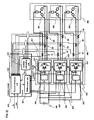
- FIG. 1 shows an overall structure of a synchronous motor drive system pertaining to Embodiment 1.
- FIG. 2 is a plan view of a synchronous motor 300 .
- FIG. 3 shows the details of the synchronous motor in FIG. 2 .
- FIG. 4 shows connections of stator coils in the synchronous motor in FIG. 2 .
- FIG. 5 shows an internal structure of a PWM control unit 401 .
- FIG. 6 shows an example pattern of a gate control signal generated by a PWM signal generation circuit 414 .
- FIG. 7A shows waveforms of a motor current specifying signal Ir_u 1 and a carrier signal fc_ 1 in the PWM signal generation circuit 414
- FIG. 7B shows waveforms of a motor current specifying signal Ir_u 2 and a carrier signal fc_ 2 in a PWM signal generation circuit 415
- FIG. 7C shows waveforms of a motor current specifying signal Ir_u 3 and a carrier signal fc_ 3 in a PWM signal generation circuit 416 .
- FIG. 8A is a top view of an inverter group 200
- FIG. 8B is a cross-sectional view thereof, taken along a line a-a′.
- FIG. 9 shows waveforms of actual motor currents (only U-phases) pertaining to the embodiment when the operating frequencies of three-phase PWM voltages output from three-phase inverters 201 , 202 and 203 are 10 kHz, 20 kHz and 10 kHz, respectively.
- FIG. 10 shows waveforms of actual motor currents (only U-phases) pertaining to the embodiment when the operating frequencies of three-phase PWM voltages output from the three-phase inverters 201 , 202 and 203 are 20 kHz, 20 kHz and 20 kHz, respectively.
- FIG. 11 shows waveforms of actual motor currents (only U-phases) pertaining to the embodiment when the operating frequencies of three-phase PWM voltages output from the three-phase inverters 201 , 202 and 203 are 10 kHz, 10 kHz and 10 kHz, respectively.
- FIG. 12 shows close-ups of the waveforms in FIG. 9 , FIG. 10 and FIG. 11 for comparison.
- FIG. 13 shows the levels of vibration caused by rotation of the synchronous motor, per frequency component of the vibration.
- FIGS. 14A-14C show positional relationships between a stator and a rotor of Embodiment 1 of the present invention.
- FIG. 15 shows temporal change of the currents applied by the three-phase inverters to the stator coils.
- FIG. 16 shows an overall structure of a synchronous motor drive system of a modification example pertaining to Embodiment 1.
- FIG. 17 shows the details of the structure of a PWM control unit 405 .
- FIG. 18 shows the details of a synchronous motor 304 .
- FIG. 19 shows connections of stator coils in the synchronous motor in FIG. 18 .
- FIGS. 20A-20C show positional relationships between a stator and a rotor of the synchronous motor 304 .
- FIG. 21 shows temporal change of the currents that are applied to the stator coils of the modification example of Embodiment 1.
- FIG. 22 shows an overall structure of a synchronous motor drive system pertaining to Embodiment 2 of the present invention.
- FIG. 23 shows the details of the structure of a PWM control unit 407 .
- FIG. 24 is a flowchart showing procedures for allocating carrier signals, performed by a carrier signal selection circuit 417 .
- FIG. 25 is a flowchart showing procedures for allocating carrier signals, pertaining to the modification example of Embodiment 1.
- FIG. 26 shows an overall structure of a synchronous motor drive system pertaining to Embodiment 3 of the present invention.
- FIG. 27 shows the structure of a gate control circuit pertaining to a modification example of Embodiment 3.
- FIG. 28 shows an overall structure of a synchronous motor drive system pertaining to Embodiment 4 of the present invention.
- FIG. 29 shows waveforms of the actual motor currents (only U-phases) in the case where the operating frequencies of the three-phase PWM voltages output from the three-phase inverters 201 , 202 and 203 are 20 kHz, 10 kHz and 20 kHz, respectively.
- FIG. 30 shows waveforms of the actual motor currents (only U-phases) in the case where the operating frequencies of the three-phase PWM voltages output from the three-phase inverters 201 , 202 and 203 are 10 kHz, 20 kHz and 20 kHz, respectively.
- FIG. 31 shows waveforms of the actual motor currents (only U-phases) in the case where the operating frequencies of the three-phase PWM voltages output from the three-phase inverters 201 , 202 and 203 are 20 kHz, 20 kHz and 10 kHz, respectively.
- FIGS. 32A , 32 B and 32 C show waveforms of the motor current specifying signals and the carrier signals in the PWM signal generation circuits 414 , 415 and 416 , respectively, in the case where the carrier signals fc_ 1 and fc_ 3 are out of phase with each other.
- FIG. 33 shows an overall structure of a synchronous motor drive system pertaining to a modification example of the present invention.
- FIG. 1 shows an overall structure of a synchronous motor drive system pertaining to Embodiment 1 of the present invention.
- the synchronous motor drive system includes a DC power source 100 , an inverter group 200 , a synchronous motor 300 , a control circuit 400 and a current detection module 500 .
- the DC power source 100 provides direct current to the inverter group 200 .
- the inverter group 200 includes three-phase inverters 201 , 202 and 203 .
- Each of the three-phase inverters 201 , 202 and 203 performs DC-AC conversion according to a gate control signal from the control circuit 400 , and provides three-phase alternate current to the synchronous motor 300 .
- the three-phase inverter 201 , 202 and 203 are composed of power circuits 207 , 208 and 209 and gate drive circuits 204 , 205 and 206 corresponding to the power circuits, respectively. All the switching devices included in the three-phase inverters 201 , 202 and 203 are included in a single module.
- the synchronous motor 300 includes three-phase coils 301 , 302 and 303 connected to the three-phase inverter 201 , 202 and 203 , respectively.
- the synchronous motor 300 is driven to rotate by AC power provided from the inverter group 200 .
- the motor currents output from the three-phase inverters 201 , 202 and 203 to the three-phase coils 301 , 302 and 303 are detected by current detectors 51 , 52 , 53 , 54 , 55 , 56 , 57 , 58 and 59 that are included in the current detection module 500 .
- the current values detected by the current detectors are input to the control circuit 400 and are used for feedback control for obtaining a desired alternate current.
- FIG. 2 is a plan view of the synchronous motor 300 .
- FIG. 3 shows the details of the synchronous motor in FIG. 2 .
- the synchronous motor 300 includes a rotor 2 and a stator 3 .
- the rotor 2 includes a rotor core 4 and a plurality of permanent magnets 5 .
- the permanent magnets 5 are arranged on the rotor core 4 at equal intervals along the rotation direction of the rotor 2 .
- the synchronous motor 300 is an interior permanent magnet synchronous motor (i.e. IPM motor).
- the permanent magnets 5 are arranged inside the rotor core.
- the permanent magnets 5 form magnetic poles 6 composed of pairs of N and S poles.
- the N poles and the S poles are alternately arranged around the stator 3 . It is defined that the pairs of N and S poles are provided every 2 ⁇ radians in terms of electrical angle.
- the interval between two adjacent magnetic poles is ⁇ radians in terms of electrical angle.
- the rotor has twenty magnetic poles.
- the electrical angle is ten times the mechanical angle.
- the stator 3 includes a plurality of stator teeth 7 facing the rotor 2 .
- the stator 3 also includes a plurality of stator coils 9 individually wound around the stator teeth 7 by concentrated winding. Every adjacent three of the stator teeth 7 belong to a different stator teeth group 8 .
- the teeth groups 8 are provided every 60° in terms of mechanical angle, equally. That is, six stator teeth groups 8 are provided in the embodiment.
- the number of the magnetic poles arranged in the rotation direction of the rotor 2 is twenty in total.
- the number of the stator teeth is 18 in total. That is, the magnetic poles and the stator teeth are displaced from each other and occur at a ratio of 10 to 9 per semicircle.
- a stator teeth group 8 b is arranged with an offset of ⁇ 60° in terms of mechanical angle, or +2 ⁇ /3 radians in terms of electrical angle.
- a stator teeth group 8 c is arranged with an offset of +60° in mechanical angle, or +4 ⁇ /3 radians (i.e. ⁇ 2 ⁇ /3 radians) in electrical angle.
- the stator teeth group 8 a , the stator teeth group 8 b and the stator teeth group 8 c are provided every 2/3 ⁇ radians in electrical angle.
- the combination of the stator teeth group 8 a , the stator teeth group 8 b and the stator teeth group 8 c is arranged twice in the rotation direction (i.e. a stator teeth group 8 a ′, a stator teeth group 8 b ′ and a stator teeth group 8 c ′ are arranged as well).
- stator teeth group 8 a The following describes the details of the structure of the stator teeth group 8 a , with reference to FIG. 3 .
- the mechanical angle between adjacent two stator coils is represented by the angle between the center lines (i.e. the dashed-dotted lines) of the stator teeth wound with the stator coils.
- the stator teeth group 8 a is composed of three adjacent stator teeth 61 a , 62 a and 63 a .
- the stator teeth 61 a , 62 a and 63 a are respectively wound with the stator coils 81 a , 82 a , and 83 a by concentrated winding such that the winding directions of the stator coils 81 a , 82 a , and 83 a are alternately opposite to each other.
- the stator tooth 61 a wound with the stator coil 81 a is positioned with an offset of +20° in mechanical angle with respect to the stator tooth 62 a wound with the stator coil 82 a . That is, the stator coil 82 a is arranged with an additional offset of + ⁇ /9 radians besides the offset of ⁇ radians in electrical angle (i.e.
- stator coil 83 a is arranged with an offset of ⁇ 20° in mechanical angle with respect to the stator coil 82 a . That is, the stator coil 83 a is arranged with an additional offset of ⁇ /9 radians besides the offset of ⁇ radians in electrical angle between the magnetic poles.
- stator teeth groups 8 b and 8 c shown in FIG. 2 . That is, similarly to the stator teeth group 8 a , three coils of each stator teeth group are arranged with an additional offset of + ⁇ /9 radians or ⁇ /9 radians in electrical angle besides the offset of ⁇ radians in electrical angle, which is the interval between the magnetic poles.
- FIG. 4 is a drawing for explaining connections of the stator coils in the synchronous motor in FIG. 2 .
- the signs “a”, “b” and “c” correspond to the coils contained in the stator teeth groups 8 a , 8 b and 8 c , respectively.
- Coil terminals 31 a , 32 a and 33 a of the three stator coils 81 a , 82 a and 83 a belonging to the stator teeth group 8 a each extend outside, and are connected to the U-phase connection terminals of the three-phase inverters 201 , 202 and 203 , respectively.
- three coil terminals 31 b , 32 b and 33 b belonging to the stator teeth group 8 b and three coil terminals 31 c , 32 c and 33 c belonging to the stator teeth group 8 c each extend outside, and are connected to the V-phase and W-phase connection terminals of the three-phase inverters 201 , 202 and 203 , respectively.
- stator coil terminals having a phrase difference of 2 ⁇ /3 radians are connected to a common neutral point. That is, the stator coil terminals 34 a , 34 b and 34 c are connected to a first neutral point, the stator coil terminals 35 a , 35 b and 35 c are connected to a second neutral point, and the stator coil terminals 36 a , 36 b and 36 c are connected to a third neutral point.
- the first, the second and the third neutral points are electrically disconnected. However, any two or all of the neutral points may be electrically connected with each other.
- the present embodiment includes two pairs of stator teeth groups 8 a , two pairs of stator teeth groups 8 b and two pairs of stator teeth groups 8 c .
- Stator teeth groups with the same suffix i.e. a, b or c
- have the same positional relationship i.e. the same electrical angle
- three adjacent groups of the six stator teeth groups may connect to a single neutral point, or three alternately-arranged groups of the six stator teeth groups may connect to a single neutral point.
- all the six stator teeth groups may connect to a single neutral point.
- stator coils 81 a , 81 b , 81 c , 81 a ′, 81 b ′ and 81 c ′ whose respective coil terminals are connected to the three-phase inverter 201 , compose the three-phase coil 301 shown in FIG. 1 .
- stator coils 82 a , 82 b , 82 c , 82 a ′, 82 b ′ and 82 c ′ compose the three-phase coil 302 shown in FIG.
- stator coils 83 a , 83 b , 83 c , 83 a ′, 83 b ′ and 83 c ′ compose the three-phase coil 303 shown in FIG. 1
- the eighteen stator teeth are arranged with intervals that are different from the intervals of the magnetic poles of the rotor. Every three stator teeth constitutes a stator teeth group. Every three stator coils of each stator teeth group are separately connected to an individual external terminal.
- stator coils contained in different stator teeth groups may be connected to the same external terminal, if conditions permit.
- stator coil 81 a contained in the stator teeth group 8 a and the stator coil 81 a ′ contained in the stator teeth group 8 a ′ may be connected to the same external terminal, because currents in the same phase are supplied thereto. Of course, they may be connected to different external terminals separately.
- control circuit 400 The following describes the details of the control circuit 400 .
- the control circuit 400 includes a PWM control unit 401 , a current detection unit 402 and a position estimating unit 403 .
- the control circuit 400 controls the operations of the three-phase inverter 201 , 202 and 203 by outputting gate control signals GU_u and GU_d thereto.
- the PWM control unit 401 outputs gate control signals to the inverters, based on motor current instruction signals Ir_u, Ir_v and Ir_w output by the current detection unit 402 .
- the current detection unit 402 receives a torque specifying signal Is and a rotation speed specifying signal or input from the outside.
- the torque specifying signal and the rotation speed specifying signal specifying the desired torque and rotation speed for driving the synchronous motor 300 , respectively.
- the current detection unit 402 determines, for each of the inverter 201 , 202 and 203 , a current phase angle ⁇ and a current amount Ia according to the torque specifying signal Is and the rotation speed specifying signal ⁇ r that have been received.
- the current detection unit 402 outputs the motor current specifying signals Ir_u, Ir_v and Ir_w to the PWM control unit 401 while monitoring the positions of the magnetic poles of the rotor of the synchronous motor and the current values of the power-supply wirings.
- the position estimating unit 403 receives at least one three-phase alternate current detection signal detected by the current detection module 500 , and calculates the inductance of the coils from the current change ratio per switching of the power circuit.
- the position estimating unit 403 estimates a rotor magnetic pole position ⁇ of the synchronous motor 300 from the inductance, and outputs the rotor magnetic pole position ⁇ to the current detection unit 402 .
- the following describes the structure and the operations of the PWM control unit 401 , with reference to FIG. 5 .
- the PWM control unit 401 includes carrier signal generation circuits 411 , 412 and 413 and PWM signal generation circuits 414 , 415 and 416 .
- the carrier signal generation circuit 411 outputs a carrier signal fc_ 1 , which is a 10 kHz triangle wave, to the PWM signal generation circuit 414 .
- the carrier signal generation circuit 412 outputs a carrier signal fc_ 2 , which is a 20 kHz triangle wave, to the PWM signal generation circuit 415 .
- the carrier signal generation circuit 413 outputs a carrier signal fc_ 3 , which is a 10 kHz triangle wave, to the PWM signal generation circuit 416 .
- Each of the PWM signal generation circuit 414 , 415 and 416 receives a carrier signal and motor current specifying signals Ir_u, Ir_v and Ir_w, and outputs a gate control signal based on the input signals.
- FIG. 6 shows an example pattern of a gate control signal generated by the PWM signal generation circuit 414 .
- the PWM signal generation circuit 414 receives the carrier signal fc_ 1 and the motor current specifying signal Ir_u 1 output from the current detection unit 402 , and compares these two signals. When the motor current specifying signal Ir_u 1 is greater than the carrier signal fc_ 1 , the PWM signal generation circuit 414 outputs a gate control signal GU_u 1 (i.e. High level in the drawing) that turns on the upper arm corresponding to the motor current specifying signal Ir_u 1 .
- GU_u 1 i.e. High level in the drawing
- the PWM signal generation circuit 414 When the motor current specifying signal Ir_u 1 is less than the carrier signal fc_ 1 , the PWM signal generation circuit 414 outputs a gate control signal GU_u 1 (i.e. Low level in the drawing) that turns off the upper arm corresponding to the motor current specifying signal Ir_u 1 .
- the logic level of the gate control signal GU_d 1 for the lower arm is reversed from the gate control signal GU_u 1 for the upper arm.
- the gate control signals GU_u and GU_d are supplied with a pause for a micro time, in which both signals are at Low level. This is for preventing a short circuit between the upper and lower arms.
- each of the PWM signal generation circuits 415 and 416 receives a motor current specifying signal and a carrier signal in the same manner as in the PWM signal generation circuit 414 , and generates a gate control signal based on the received signals.
- FIG. 7A shows the waveforms of the motor current specifying signal Ir_u 1 and the carrier signal fc_ 1 in the PWM signal generation circuit 414 .
- FIG. 7B shows the waveforms of the motor current specifying signal Ir_u 2 and the carrier signal fc_ 2 in the PWM signal generation circuit 415 .
- FIG. 7C shows the waveforms of the motor current specifying signal Ir_u 3 and the carrier signal fc_ 3 in the PWM signal generation circuit 416 .
- the gate control signal generated by the PWM signal generation circuit 414 by using the carrier signal fc_ 1 as a 10 kHz triangle wave is input to the gate drive circuit 204 of the three-phase inverter 201 .
- the gate control signal generated by the PWM signal generation circuit 415 by using the carrier signal fc_ 2 as a 20 kHz triangle wave is input to the gate drive circuit 205 of the three-phase inverter 202 .
- the gate control signal generated by the PWM signal generation circuit 416 by using the carrier signal fc_ 3 as a 10 kHz triangle wave is input to the gate drive circuit 206 of the three-phase inverter 203 .
- the operating frequency of the three-phase PWM voltages output from the three-phase inverters 201 , 202 and 203 in the present embodiment will be 10 kHz, 20 kHz and 10 kHz, respectively.
- the three-phase PWM voltages output from the three-phase inverters 201 , 202 and 203 are input to the three-phase coils 301 , 302 and 303 , respectively.
- the three-phase PWM voltages input to the stator coils 81 a and 83 a are with 10 kHz
- the three-phase PWM voltage input to the stator coil 82 a between the stator coils 81 a and 83 a are with 20 kHz.
- control circuit 400 This concludes the description of the details of the control circuit 400 .
- FIG. 8A is a top view of the inverter group 200
- FIG. 8B is a cross-sectional view thereof, taken along a line a-a′.
- the inverter group 200 constitutes a single module, in which the three-phase inverters 201 , 202 and 203 are arranged next to each other on an insulating substrate 240 and are sealed with a resin mold 250 such as an epoxy resin.
- the three-phase inverter 201 and the three-phase inverter 203 operate at the operating frequency of 10 kHz, and the three-phase inverter 202 operates at the operating frequency of 20 kHz.
- the three-phase inverter 202 generates a larger amount of heat than the other three-phase inverters.
- the three-phase inverter 202 is structured from a switching device with use of a wide-bandgap semiconductor such as silicon carbide and gallium nitride with excellent thermal resistance, which has a wider bandgap than Si semiconductors, whereas the three-phase inverter 201 and the three-phase inverter 203 are structured from switching devices with use of a cheap Si semiconductor.
- the heat gradient of the three-phase inverters 201 , 202 and 203 is substantially symmetry with respect to the three-phase inverter 202 . This results in high reliability. Also, with such a structure, it is possible to provide a module at a lower cost than structuring the module only with a wide-bandgap semiconductor.
- IPM Intelligent Power Module
- FIG. 9 shows the waveforms of the actual motor currents (only U-phases) pertaining to the embodiment when the operating frequencies of the three-phase PWM voltages output from the three-phase inverters 201 , 202 and 203 are 10 kHz, 20 kHz and 10 kHz, respectively.
- FIG. 10 is similar to the embodiment. However, FIG. 10 shows the waveforms of the actual motor currents (only U-phases) pertaining to the embodiment when the operating frequencies of the three-phase PWM voltages output from the three-phase inverters 201 , 202 and 203 are 20 kHz, 20 kHz and 20 kHz, respectively. Similarly, FIG.
- FIG. 11 shows the waveforms of the actual motor currents (only U-phases) pertaining to the embodiment when the operating frequencies of the three-phase PWM voltages output from the three-phase inverters 201 , 202 and 203 are 10 kHz, 10 kHz and 10 kHz, respectively.
- FIG. 12 shows close-ups of the waveforms in FIG. 9 , FIG. 10 and FIG. 11 for comparison.
- the current ripples, or the waveform distortions of the actual motor currents applied to the three-phase coils 301 , 302 and 303 are reduced when all the operating frequencies are 20 kHz.
- the current ripples, or the waveform distortions of the actual motor currents applied to the three-phase coils 301 , 302 and 303 are large when all the operating frequencies are 10 kHz.
- the waveform distortion in the second stage where all the operating frequencies 20 kHz is approximately 1 ⁇ 2 of the waveform distortion in the third stage where all the operating frequencies are 10 kHz. Waveform distortions of an actual motor current cause serious problems in driving a motor, namely, noise and vibration of the motor.
- the distortion of the actual motor current waveform in the first stage, of the three-phase coil to which a 10 kHz three-phase PWM voltage is input in the present embodiment is within a range from approximately 1 ⁇ 2 to approximately 3 ⁇ 5 of that in the third stage where all the operating frequencies are 10 kHz.
- FIG. 13 shows the levels of vibration caused by rotation of the synchronous motor, per frequency component of the vibration.
- the first stage shows vibration in the embodiment when the three-phase inverters 201 , 202 and 203 are operated with carrier signals with the frequencies of 10 kHz, 20 kHz and 10 kHz, respectively.
- the second stage shows the case where all the three-phase inverters are operated with a carrier signal with the frequency of 10 kHz.
- the third stage shows the case where all the three-phase inverters are operated with a carrier signal with the frequency of 20 kHz.
- the vibration is reduce to a low level under the conditions of the present embodiment than under other conditions.
- the effect of reducing the vibration is achieved in the whole synchronous motor drive system with the resonance frequency within such frequency bands.
- the vibration level in the second stage where all the three-phase inverters are operated with a carrier signal of 10 kHz, is approximately ⁇ 70 dB.
- the vibration level under the conditions of the present invention is reduced to approximately ⁇ 80 dB as shown in the second stage.
- the vibration level in the second stage where all the three-phase inverters are operated with a carrier signal of 10 kHz, is approximately ⁇ 77 dB.
- the vibration level under the conditions of the present invention is reduced to approximately ⁇ 80 dB as shown in the first stage.
- the vibration level in the second stage where all the three-phase inverters are operated with a carrier signal of 10 kHz, is approximately ⁇ 70 dB.
- the vibration level under the conditions of the present invention is reduced to approximately ⁇ 90 dB as shown in the first stage.
- the switching loss is reduced to be lower than the case where all the three-phase inverters are operated based on gate control signals generated with a carrier signal of 20 kHz.
- the waveform distortion of the motor current due to the ripples is reduced to be a lower level than the case where the all the three-phase inverters are operated based on gate control signals generated with the frequency of 10 kHz.
- implementation of the present invention provides a motor drive system that solves important problems such as switching loss of the three-phase inverters and the EMC, caused along with the increase of the operating frequency, and realizes low noise and low vibration in the motor drive.
- FIGS. 14A-14C show positional relationships between the stator and the rotor of Embodiment 1 of the present invention.
- FIG. 14A-14C show the positional relationship in the case where the rotor is rotated anti-clockwise by 2° in mechanical angle (i.e. ⁇ /9 radians in electrical angle) at a time.
- FIG. 15 shows the temporal change of the currents applied by the three-phase inverters to the stator coils.
- the time points (a), (b) and (c) in FIG. 15 correspond to the positional relationships shown in FIG. 14A , FIG. 14B and FIG. 14C , respectively.
- points between magnetic poles of the rotor are indicated by the signs 10 and 11 .
- Each of the points 10 and 11 between the magnetic poles of the rotor is a magnetic neutral point between an N magnetic pole and an S magnetic pole each generated with a permanent magnet located in the rotor.
- each neutral point is located between the magnets, in terms of the physical locations as well.
- the point 10 shows the magnetic neutral point at which the magnetic property changes from N to S anti-clockwise
- the point 11 shows the magnetic neutral point at which the magnetic property changes from S to N anti-clockwise.
- the point 11 ′ is at the same position as the point 11 in terms of electrical angle, but at different positions in terms of mechanical angle.
- FIG. 14A as shown as the dashed-dotted line, the center point of the stator tooth 63 a and the point 11 between the rotor magnetic poles are in line. If this is the case, the magnet torque, which is the torque of the permanent magnet, reaches its maximum when the phase of the current supplied is controlled such that the current that flows through the stator coil 83 a connected to the inverter 203 is controlled so as to be maximized. As explained in FIG. 3 , the angle between adjacent magnetic poles (i.e. 18°) and the angle between adjacent stator teeth (20°) are different.
- the rotor is rotated anti-clockwise from that shown in FIG. 14A by 2° in mechanical angle (i.e. ⁇ /9 radians in electrical angle).
- the center point of the stator tooth 62 a and the point 10 between the rotor magnetic poles are in line. If this is the case, the magnet torque, which is the torque of the permanent magnet, reaches its maximum when the phase of the current supplied is controlled such that the current that flows through the stator coil 82 a connected to the inverter 202 is controlled so as to be maximized.
- the center point of the stator tooth 63 a and the point 11 between the rotor magnetic poles, and the center point of the stator tooth 61 a and the point 11 ′ between the rotor magnetic poles are not in line.
- the rotor is rotated anti-clockwise from that shown in FIG. 14B by 2° in mechanical angle (i.e. ⁇ /9 radians in electrical angle).
- the center point of the stator tooth 61 a and the point 11 ′ between the rotor magnetic poles are in line.
- the magnet torque which is the torque of the permanent magnet
- the phase of the current supplied is controlled such that the current that flows through the stator coil 81 a connected to the inverter 201 is controlled so as to be maximized.
- the center point of the stator tooth 63 a and the point 11 between the rotor magnetic poles, and the center point of the stator tooth 62 a and the point 10 between the rotor magnetic poles are not in line.
- the phase of the current to be applied is controlled such that the currents flowing through the stator coils 81 a , 82 a and 83 a are at their maximum when the positional relationships are as shown in FIGS. 14A , 14 B and 14 C, that is, when each of the respective center points of the stator teeth 61 a , 62 a and 63 a are in line with a point between rotor magnetic poles. This maximizes the magnet torque for each of the stator teeth, thereby increasing the total torque.
- the vertical axis shows the currents applied by the three-phase inverters 201 , 202 and 203 to the coil terminals 31 a , 32 a and 33 a (i.e. to the stator coils 81 a , 82 a and 83 a ), and the horizontal axis shows the time.
- the current applied to the coil terminal 33 a is set ahead of the current applied to the coil terminal 32 a by ⁇ /9 radians, and the current applied to the coil terminal 31 a is delayed from the current applied to the coil terminal 32 a by ⁇ /9 radians.
- the intervals of the rotor magnetic poles are 18° in mechanical angle (i.e. ⁇ radians in electrical angle) whereas the intervals of the three stator teeth in each stator teeth group are 20° in mechanical angle, instead of 18°.
- the synchronous motor 300 reduces the cogging torque, which is torque ripples while no electrical power is being supplied.
- each of the stator teeth in each stator teeth group is located with a phase difference of ⁇ /9 radians with respect to ⁇ radians in electrical angle.
- each stator tooth yields the same amount of torque.
- the torque ripple having a fundamental period of ⁇ /3 radians is cancelled, and the torque yielded by each stator tooth is maximized, whereby the overall torque is increased.
- the synchronous motor pertaining to Embodiment 1 is what is called an interior permanent magnet synchronous motor that has permanent magnets arranged inside the rotor core.
- the synchronous motor utilizes reluctance torque resulting from a difference in magnetoresistance, along with the magnet torque generated by the magnets.
- FIG. 16 shows an overall structure of a synchronous motor drive system pertaining to this modification.
- the inverter group 200 , the synchronous motor 300 , the control circuit 400 and the current detection module 500 included in the system shown in FIG. 1 are replaced with a inverter group 210 , a synchronous motor 304 , a control circuit 404 and a current detection module 501 , respectively.
- the inverter group 210 has the same structure as the inverter group 200 except that the three-phase inverter 203 is removed.
- the synchronous motor 304 includes two three-phase coils 305 and 306 .
- the control circuit 404 has the same structure as the control circuit 400 shown in FIG. 1 except that the PWM control unit 401 is replaced with a PWM control unit 405 .
- FIG. 17 shows the details of the structure of the PWM control unit 405 .
- the PWM control unit 405 has the same structure as the PWM control unit 401 shown in FIG. 5 except that the carrier signal generation circuit 413 and the PWM signal generation circuit 416 are removed. With this structure, a gate control signal using a 10 kHz carrier signal is output from the PWM control unit 405 to the gate drive circuit 204 of the three-phase inverter 201 , and a gate control signal using a 20 kHz carrier signal is output to the gate drive circuit 205 of the three-phase inverter 202 .
- the synchronous motor 304 has a structure similar to the structure of synchronous motor 300 shown in FIG. 2 . However, the manner in which a stator coil is wound around each stator tooth is different from the synchronous motor 300 .
- FIG. 18 shows the details of the synchronous motor 304 .
- the following describes the details of the structure of the stator teeth group 8 a , with reference to FIG. 18 .
- the mechanical angle between adjacent stator teeth is represented by the angle between the center lines (i.e. the dashed-dotted lines) of the corresponding stator teeth around which the stator coils are wound.
- the stator teeth group 8 a is composed of three adjacent stator teeth 71 a , 72 a and 73 a.
- the stator tooth 71 a is positioned with an offset of +20° in mechanical angle with respect to the stator tooth 72 a . That is, the stator coil 83 a is arranged with an additional offset of + ⁇ /9 radians besides the offset of ⁇ radians in electrical angle (i.e. 18° in mechanical angle) between the magnetic poles.
- the stator tooth 73 a is positioned with an offset of ⁇ 20° in mechanical angle with respect to the stator tooth 72 a . That is, the stator coil 73 a is arranged with an additional offset of ⁇ /9 radians besides the offset of ⁇ radians in electrical angle between the magnetic poles.
- stator tooth 71 a part of the stator coil 91 a (the number of turns is N 1 ) is wound.
- stator tooth 73 a part of the stator coil 92 a (the number of turns is N 2 ) is wound.
- the stator tooth 72 a the rest of the stator coil 91 a (the number of turns is N 21 ) and the rest of the stator coil 92 a (the number of turns is N 22 ) are wound.
- stator coil 91 a In the stator coil 91 a , the part wound around the stator tooth 71 a and the part wound around the stator tooth 72 a generate magnetic fields having reversed polarities. Similarly, in the stator coil 92 a , the part wound around the stator tooth 72 a and the part wound around the stator tooth 73 a generate magnetic fields having reversed polarities. Furthermore, when currents in the same phase are supplied to the stator coils 91 a and 92 a , the parts wound around the stator tooth 72 a generate magnetic fields having the same polarity.
- stator teeth groups 8 b and 8 c shown in FIG. 18 both adjacent to the stator teeth group 8 a , have the same structure as the stator teeth group 8 a shown in FIG. 18 .
- FIG. 19 is a drawing for explaining connections of the stator coils in the synchronous motor in FIG. 18 .
- the signs “a”, “b” and “c” correspond to the coils contained in the stator teeth groups 8 a , 8 b and 8 c , respectively.
- the coil terminal 21 a is connected to the U-phase connection terminal of the three-phase inverters 201
- the coil terminal 23 a is connected to the U-phase connection terminal of the three-phase inverter 202 .
- two coil terminals 21 b and 23 b belonging to the stator teeth group 8 b and two coil terminals 21 c and 23 c belonging to the stator teeth group 8 c separately extend outside, and are connected to the V-phase and W-phase connection terminals of the three-phase inverters 201 and 202 respectively.
- stator coil terminals having a phrase difference of 2 ⁇ /3 radians are connected to a common neutral point. That is, the stator coil terminals 22 a , 22 b and 22 c are connected to a first neutral point, and the stator coil terminals 24 a , 24 b and 24 c are connected to a second neutral point.
- the first and the second neutral points are electrically disconnected. However, these neutral points may be electrically connected with each other.
- the present embodiment includes two pairs of stator teeth groups 8 a , two pairs of stator teeth groups 8 b and two pairs of stator teeth groups 8 c .
- Stator teeth groups with the same suffix i.e. a, b or c
- have the same positional relationship i.e. the same electrical angle
- three adjacent pairs of the six pairs of stator teeth groups may connect to a single neutral point, or three alternately-arranged pairs of the six pairs of stator teeth groups may connect to a single neutral point.
- all the six pairs of stator teeth groups may connect to a single neutral point.
- stator coils 91 a , 91 b , 91 c , 91 a ′, 91 b ′ and 91 c ′ whose respective coil terminals are connected to the three-phase inverter 201 , compose the three-phase coil 305 shown in FIG. 16 .
- stator coils 92 a , 92 b , 92 c , 92 a ′, 92 b ′ and 92 c ′ compose the three-phase coil 306 shown in FIG. 16 .
- the eighteen stator teeth are arranged with intervals that are different from the intervals of the magnetic poles of the rotor. Every three stator teeth constitutes a stator teeth group. Every two stator coils of each stator teeth group are separately connected to an individual external terminal.
- stator coils contained in different stator teeth groups may be connected to the same external terminal, if conditions permit.
- stator coil 91 a contained in the stator teeth group 8 a and the stator coil 91 a ′ contained in the stator teeth group 8 a ′ may be connected to the same external terminal, because currents in the same phase is supplied thereto. Of course, they may be connected to different external terminals separately.
- the synchronous motor drive system pertaining to this modification includes a drive apparatus for supplying currents in different phases to a plurality of coil terminals of the synchronous motor. The following explains the drive apparatus and methods of applying power.
- FIGS. 20A-20C show positional relationships between the stator and the rotor of this modification of the present invention.
- FIG. 20A-20C show the positional relationship in the case where the rotor is rotated anti-clockwise by 2° in mechanical angle (i.e. ⁇ /9 radians in electrical angle) at a time.
- FIG. 21 shows the temporal change of the currents applied by to the stator coils pertaining to this modification.
- the time points (a), (b) and (c) in FIG. 21 correspond to the positional relationships shown in FIG. 20A , FIG. 20B and FIG. 20C , respectively.
- each of the points 10 and 11 between the magnetic poles of the rotor is a magnetic neutral point between an N magnetic pole and an S magnetic pole each generated with a permanent magnet located in the rotor.
- each neutral point is located between the magnets, in terms of the physical locations as well.
- the point 10 shows the magnetic neutral point at which the magnetic property changes from N to S anti-clockwise
- the point 11 shows the magnetic neutral point at which the magnetic property changes from S to N anti-clockwise.
- the point 11 ′ is at the same position as the point 11 in terms of electrical angle, but at different positions in terms of mechanical angle.
- FIG. 20A as shown as the dashed-dotted line, the center point of the stator tooth 73 a and the point 11 between the rotor magnetic poles are in line. If this is the case, the magnet torque reaches its maximum when the phase of the current supplied is controlled such that the current that flows through the stator coil 93 a is controlled so as to be maximized. As explained in FIG. 18 , the angle between adjacent magnetic poles (i.e.) 18° and the angle between adjacent stator teeth (20°) are different.
- FIG. 20B the rotor is rotated anti-clockwise from that shown in FIG. 20A by 2° in mechanical angle (i.e. ⁇ /9 radians in electrical angle).
- the center point of the stator tooth 72 a and the point 10 between the rotor magnetic poles are in line.
- the center point of the stator tooth 73 a and the point 11 between the rotor magnetic poles, and the center point of the stator tooth 71 a and the point 11 ′ between the rotor magnetic poles are not in line.
- the rotor is rotated anti-clockwise from that shown in FIG. 20B by 2° in mechanical angle (i.e. ⁇ /9 radians in electrical angle).
- the center point of the stator tooth 71 a and the point 11 ′ between the rotor magnetic poles are in line. If this is the case, the magnet torque reaches its maximum when the phase of the current supplied is controlled such that the current that flows through the stator coil 91 a is controlled so as to be maximized.
- the center point of the stator tooth 73 a and the point 11 between the rotor magnetic poles, and the center point of the stator tooth 72 a and the point 10 between the rotor magnetic poles are not in line.
- the phase of the current to be applied is controlled such that the currents flowing through the stator coils 91 a and 92 a are at their maximum when the positional relationships are as shown in FIGS. 20A and 20C , that is, when each of the respective center points of the stator teeth 71 a and 73 a are in line with a point between rotor magnetic poles.
- the current flowing through the stator coil 92 a is at its maximum when the positional relationship is as shown in FIG. 20A , that is, when the center point of the stator tooth 73 a is in line with the point 11 between rotor magnetic poles. This maximizes the magnet torque to be generated by the stator tooth 73 a .
- the composition of the vectors of the currents flowing through the stator coils 91 a and 92 a is at its maximum when the positional relationship is as shown in FIG. 20B , that is, when the center point of the stator tooth 72 a is in line with the point 10 between rotor magnetic poles. This maximizes the magnet torque to be generated by the stator tooth 72 a .
- the current flowing through the stator coil 91 a is at its maximum when the positional relationship is as shown in FIG. 20C , that is, when the center point of the stator tooth 71 a is in line with the point 11 ′ between rotor magnetic poles. This maximizes the magnet torque to be generated by the stator tooth 71 a . This maximizes the magnet torque for each of the stator teeth, thereby increasing the total torque.
- the vertical axis shows the currents applied by the three-phase inverters 201 and 202 to the coil terminals 21 a and 23 a (i.e. to the stator coils 91 a and 92 a ), and the horizontal axis shows the time.
- the current applied to the coil terminal 23 a is set ahead of the current applied to the coil terminal 21 a by 2 ⁇ /9 radians.
- stator tooth 73 a is arranged with an additional offset of ⁇ /9 radians to the offset of ⁇ radians, in terms of electrical angle.
- stator tooth 71 a is arranged with an additional offset of + ⁇ /9 radians to the offset of ⁇ radians, in terms of electrical angle.
- the PWM control is performed by using a lower frequency carrier signal in one of the two three-phase inverters than the other.
- the increase of the waveform distortion of the actual motor current is suppressed by the following action. That is, the changes of magnetic flux caused by the current applied to the three-phase coil 305 with the operating frequency of 20 kHz suppresses the changes of magnetic flux caused by the current applied to the three-phase coil 306 with the operating frequency of 10 kHz.
- FIG. 22 shows an overall structure of a synchronous motor drive system pertaining to Embodiment 2 of the present invention.
- the synchronous motor drive system shown in FIG. 22 has the same structure as the synchronous motor drive system shown in FIG. 1 except that the inverter group 200 and the control circuit 400 are replaced with an inverter group 220 and a control circuit 406 .
- the following explains the differences from the synchronous motor drive system pertaining to Embodiment 1.
- Three-phase inverters 221 , 222 and 223 included in the inverter group 220 are different from the three-phase inverters 201 , 202 and 203 pertaining to Embodiment 1 in that they have temperature sensors 61 , 62 and 63 , respectively.
- the temperature sensors 61 , 62 and 63 cyclically measure the temperatures of switching devices included in power circuits 227 , 228 and 229 of the three-phase inverters, respectively.
- the temperature sensors 61 , 62 and 63 output temperature detection signals T 1 , T 2 and T 3 corresponding to the power circuits 227 , 228 and 229 to the control circuit 406 , respectively.
- the control circuit 406 has the same structure as the control circuit 400 shown in FIG. 1 except that the PWM control unit 401 is replaced with a PWM control unit 407 .
- FIG. 23 shows the details of the structure of the PWM control unit 407 .
- the PWM control unit 405 has the same structure as the PWM control unit 401 except that a carrier signal selection circuit 417 is added thereto.
- the carrier signal selection circuit 417 allocates the carrier signals fc_ 1 , fc_ 2 and fc_ 3 to the PWM signal generation circuits 414 , 415 and 416 based on the temperature detection signals T 1 , T 2 and T 3 input from the temperature sensors 61 , 62 and 63 .
- the carrier signal selection circuit 417 determines the allocation of the carrier signals to the PWM signal generation circuits such that a gate control signal with a higher operating frequency will be output to the gate drive circuit corresponding to the power circuit that exhibits the lowest temperature among the power circuit 227 , 228 and 229 .
- FIG. 24 is a flowchart showing procedures for allocating carrier signals, performed by the carrier signal selection circuit 417 .
- the carrier signal selection circuit 417 compares the temperatures of the power circuits through the judgments at Step S 2 and Step S 3 .
- the carrier signal selection circuit 417 When the temperature indicated by the temperature detection signal T 1 is lower than the temperatures indicated by the temperature detection signals T 2 and T 3 (Step S 2 : YES), the carrier signal selection circuit 417 outputs a carrier signal fc_ 2 to the PWM signal generation circuit 414 , and outputs carrier signals fc_ 1 and fc_ 3 to the PWM signal generation circuits 415 and 416 , respectively (Step S 3 ).
- the carrier signal fc_ 2 has the frequency of 20 kHz
- the carrier signals fc_ 1 and fc_ 3 have the frequency of 10 kHz.
- Step S 2 when the temperature indicated by the temperature detection signal T 1 is not lower than the temperature detection signals T 2 and T 3 (Step S 2 : NO), the carrier signal selection circuit 417 compares the temperature detection signals T 2 and T 3 . When the temperature indicated by the temperature detection signal T 2 is lower than the temperature indicated by the temperature detection signals T 3 (Step S 4 : YES), the carrier signal selection circuit 417 outputs a carrier signal fc_ 2 to the PWM signal generation circuit 415 , and outputs carrier signals fc_ 1 and fc_ 3 to the PWM signal generation circuits 414 and 416 , respectively (Step S 5 ).
- the carrier signal fc_ 2 has the frequency of 20 kHz
- the carrier signals fc_ 1 and fc_ 3 have the frequency of 10 kHz.
- Step S 2 when the temperature indicated by the temperature detection signal T 2 is not lower than the temperature indicated by the temperature detection signal T 3 (Step S 4 : NO), the carrier signal selection circuit 417 outputs a carrier signal fc_ 2 to the PWM signal generation circuit 416 , and outputs carrier signals fc_ 1 and fc_ 3 to the PWM signal generation circuits 415 and 416 , respectively (Step S 6 ).
- the carrier signal fc_ 2 has the frequency of 20 kHz
- the carrier signals fc_ 1 and fc_ 3 have the frequency of 10 kHz.
- the one inverter with the power circuit having the lowest temperature among the three-phase inverters 221 , 222 and 223 is provided with a gate control signal that is based on the carrier signal having a higher frequency than the others.
- the three-phase inverter in the three-phase inverter to operate with a carrier signal of 20 kHz, its power circuit generates a larger among of heat than the three-phase inverters to operate with a carrier signal of 10 kHz.
- the relationship among the temperatures of the three-phase inverters would change at some stage.
- the temperatures of the power circuits in the three-phase inverters are measured cyclically, and the procedures from Step S 1 to Step S 6 are repeated based on the latest temperature detection signals T 1 , T 2 and T 3 .
- the three-phase inverter with the power circuit exhibiting the lowest temperature at each stage is provided with a gate control signal that is based on a carrier signal having a higher frequency than the other three-phase inverters.
- concentration of the heat load to some of the power circuits 227 , 228 and 229 is prevented, which serves to improve the reliability of the system.
- the iron loss of the stator coil to which the power is provided by a three-phase inverter driving with a higher carrier frequency is greater than the other stator coils, and therefore generates a larger amount of heat.
- the three-phase inverters to which the gate control signal that is based on the carrier signal with the higher frequency is provided alternates sequentially.
- the amounts of heat generated by the stator coils are equalized. Such an effect also serves to improve the reliability of the system.
- control circuit 406 may be described with an application program and may be realized with a microcomputer system performing the program.
- the heat loads on the three-phase inverters 221 , 222 and 223 can be equalized by measuring the temperatures of the power circuits of the three-phase inverters and supplying a gate control signal that is based on the carrier signal having the highest frequency to the inverter with the lowest temperature.
- a gate control signal that is based on the carrier signal having the highest frequency to the inverter with the lowest temperature.
- the supply destination of the gate control signal alternates in a cycle with which the excessive temperature of the three-phase inverter having been driving with the high-frequency carrier signal decreases while another three-phase inverter is driving with a high-frequency carrier signal.
- Such a cycle is determined based on the structure of the inverter module. For example, if three three-phase inverters are provided parallely within a module, the radiation performance of the three-phase inverter in the middle is poorer than the other inverters on both sides. In view of this, it is preferable that the period in which a gate control signal that is based on the high-frequency carrier signal is supplied to the three-phase inverter in the middle is shorter than the three-phase inverters on both sides.
- the destination of the gate control signal that is based on the high-frequency carrier signal may be alternated among all the three-phase inverters at constant intervals.
- FIG. 25 is a flowchart showing procedures for allocating carrier signals, performed by the carrier signal selection circuit 417 pertaining to this modification.
- the carrier signal selection circuit 417 includes a timer for outputting timeout signals at predetermined intervals, and a working memory. Firstly, the carrier signal selection circuit 417 sets 0 to the variable X on the working memory at Step S 11 , and repeats the loop from Step S 12 to Step S 18 .
- the carrier signal selection circuit 417 waits for the timer to output a timeout signal (Step S 12 ), and obtains a reminder left when the variable X is divided by 3.
- the carrier signal selection circuit 417 When the remainder is 0 (Step S 13 : YES), the carrier signal selection circuit 417 outputs a carrier signal fc_ 2 to the PWM signal generation circuit 414 , and outputs carrier signals fc_ 1 and fc_ 3 to the PWM signal generation circuits 415 and 416 , respectively (Step S 14 ).
- the carrier signal fc_ 2 has the frequency of 20 kHz
- the carrier signals fc_ 1 and fc_ 3 have the frequency of 10 kHz.
- the carrier signal selection circuit 417 When the remainder is 1 (Step S 15 : YES), the carrier signal selection circuit 417 outputs a carrier signal fc_ 2 to the PWM signal generation circuit 415 , and outputs carrier signals fc_ 1 and fc_ 3 to the PWM signal generation circuits 414 and 416 , respectively (Step S 16 ).
- the carrier signal fc_ 2 has the frequency of 20 kHz
- the carrier signals fc_ 1 and fc_ 3 have the frequency of 10 kHz.
- the carrier signal selection circuit 417 When the remainder is 2 (Step S 15 : NO), the carrier signal selection circuit 417 outputs a carrier signal fc_ 2 to the PWM signal generation circuit 416 , and outputs carrier signals fc_ 1 and fc_ 3 to the PWM signal generation circuits 414 and 415 , respectively (Step S 17 ).
- the carrier signal fc_ 2 has the frequency of 20 kHz
- the carrier signals fc_ 1 and fc_ 3 have the frequency of 10 kHz.
- the carrier signal selection circuit 417 increments the variable X at Step S 18 while repeating the loop.
- a gate control signal that is based on the high-frequency carrier signal is supplied to the three-phase inverters 221 , 222 and 223 in this order, at the predetermined intervals at which the timer outputs timeout signals.
- intervals at which the timer outputs timeout signals may be determined within the range where the temperature of the heat generated from the three-phase inverters does not rise beyond the acceptable temperature when gate control signals based on the high-frequency carrier signal are supplied continually.
- FIG. 26 shows an overall structure of a synchronous motor drive system pertaining to Embodiment 3 of the present invention.
- the synchronous motor drive system shown in FIG. 26 has the same structure as the synchronous motor drive system shown in FIG. 1 except that the inverter group 200 is replaced with an inverter group 230 .
- the following explains the differences from the synchronous motor drive system pertaining to Embodiment 1.
- the inverter group 230 pertaining to this embodiment is characterized by gate drive circuits 231 , 232 and 233 of the three-phase inverters.
- the gate drive circuits 231 , 232 and 233 have gate resistances between their corresponding power circuits 207 , 208 and 209 and them.
- the resistance value of the gate resistance for the gate drive circuit 232 to which a gate control signal based on a 20 kHz carrier signal is input from the PWM control unit 401 , is lower than the gate drive circuits 231 and 233 to which a gate control signal based on a 10 kHz carrier signal is input.
- the switching speed is higher than the others because the channel of the switching device accumulates the electrical charge quicker than the others.
- the switching device in the power circuit 208 suffers less switching loss per switching operation than the switching devices in the other power circuits.
- the switching loss per switching operation in the power circuit 208 that drives based on the high-frequency carrier signal is lower than the other power circuits. This keeps the balance among the switching losses that occur in the power circuits 207 , 208 and 209 per unit time. Therefore, concentration of the heat load to some of the power circuits is prevented, which serves to improve the reliability of the system.
- Embodiment 2 Combining Embodiment 2 with Embodiment 3 is highly effective.
- the temperature sensors measure the temperatures of the power circuits of the three-phase inverters, and the PWM control unit outputs a gate control signal with use of 20 kHz carrier frequency to the gate drive circuit corresponding to the power circuit whose measured temperature is the lowest, and outputs a gate control signal with use of 10 kHz carrier frequency to the other two gate drive circuits.
- each gate control circuit has a gate resistance 242 and a switch 243 , which are parallely arranged between a gate drive signal output unit 241 and the gate terminal of the power circuit 207 .
- the control circuit having such a structure outputs gate drive signals by turning on the switch 243 when a gate control signal with use of a 20 kHz carrier frequency is input from the PWM control unit, and turning off the switch 243 when a gate control signal with use of a 10 kHz carrier frequency is input from the PWM control unit.
- the switching device of its power circuit performs the switching at a higher speed than the other three-phase inverters.
- the carrier frequencies of the gate control signals supplied to the three-phase inverters are switched based on the changes in the temperatures of the power circuits, and the switching speed of the power circuit that drives based on the higher-frequency carrier signal than the others at the moment is set to be higher than the switching speeds of the other power circuits. Therefore, concentration of the heat load to some of the power circuits is prevented, which serves to improve the reliability of the system.
- FIG. 28 shows an overall structure of a synchronous motor drive system pertaining to Embodiment 3 of the present invention.
- the synchronous motor drive system shown in FIG. 28 has the same structure as the synchronous motor drive system shown in FIG. 1 except that the position estimating unit 403 is replaced with a position estimating unit 409 .
- the following explains the differences from the synchronous motor drive system pertaining to Embodiment 1.
- the position estimating unit 409 receives, among the three-phase alternate current detection signals detected by the current detection module 500 , the three-phase alternate current detection signals relating to the three-phase inverter 201 detected by the current detectors 51 , 52 and 53 , and calculates the inductance of the coils from the current change ratio per switching by the three-phase inverter 201 .
- the position estimating unit 409 estimates a rotor magnetic pole position ⁇ of the synchronous motor 300 from the inductance.
- the three-phase inverters 201 , 202 and 203 operate according to gate control signals with use of 10 kHz, 20 kHz and 10 kHz carrier signals, respectively.
- the operating frequency of the carrier signal corresponds to the period for control calculation.
- sensorless control for estimating the magnetic pole position ⁇ a longer control calculation period can be used for the sensorless control when the output from the three-phase inverters that operate with the 10 kHz operating frequency is used than when the output from the three-phase inverter that operates with the 20 kHz operating frequency is used.
- the magnetic pole position ⁇ is estimated by using the output from the three-phase inverter that operate with the lower carrier frequency.
- Embodiment 1 shows the case in which, among the three stator coils shown in FIG. 3 , the three-phase PWM voltage applied to the stator coils 81 a and 83 a on both side is 10 kHz, and the three-phase PWM voltage applied to the stator coil 82 a in the middle is 20 kHz.
- the present invention is not limited to this. Some effect can be expected with the structure in which one of the stator coil pair arranged along the circumference of the stator is supplied with a three-phase PWM voltage based on a carrier signal with a lower frequency than the other one.
- FIG. 29 shows the waveforms of the actual motor currents (only U-phases) in the case where the operating frequencies of the three-phase PWM voltages output from the three-phase inverters 201 , 202 and 203 are 20 kHz, 10 kHz and 20 kHz, respectively.
- FIG. 30 shows the waveforms of the actual motor currents (only U-phases) in the case where the operating frequencies of the three-phase PWM voltages output from the three-phase inverters 201 , 202 and 203 are 10 kHz, 20 kHz and 10 kHz, respectively.
- FIG. 29 shows the waveforms of the actual motor currents (only U-phases) in the case where the operating frequencies of the three-phase PWM voltages output from the three-phase inverters 201 , 202 and 203 are 10 kHz, 20 kHz and 10 kHz, respectively.
- the currents I_u 1 , I_u 2 and I_u 3 are the actual motor currents input to the stator coils 81 a , 82 a and 83 a , respectively.
- the carrier signals, on which the input three-phase PWM voltages are based on have different frequencies between the pair of adjacent stator coils 81 a and 82 a and between another pair of stator coils 82 a and 83 a .
- the carrier signals, on which the input three-phase PWM voltages are based on have different frequencies between the pair of adjacent stator coils 81 a and 82 a .
- the carrier signals, on which the input three-phase PWM voltages are based on have different frequencies between the pair of adjacent stator coils 82 a and 83 a .
- the change of magnetic flux caused by the current applied to the stator coil with the operating frequency of 20 kHz suppresses the change of magnetic flux caused by the current applied to the stator coil with the operating frequency of 10 kHz. This serves to suppress the increase of the waveform distortion of the actual motor currents.
- the switching loss is reduced from the case where all the three-phase inverters operate with the frequency of 20 kHz.
- the present invention is not limited to this, and any number is applicable as long as it is an integer no less than two. The following considers the case where the number of the stator teeth included in the stator teeth group is m.
- the adjacent stator teeth in the stator teeth group can be arranged at the interval corresponding to ( ⁇ +2 ⁇ /3m) radians in electrical angle at the maximum. Also, in the case where the stator coils wound around the adjacent stator teeth generate magnetic fields having reversed polarities when applied with currents in the same phase, currents in different phases within the range of ⁇ 2 ⁇ /3m radians may be supplied to the stator coils.
- the adjacent stator teeth in the stator teeth group are arranged at interval corresponding to ( ⁇ + ⁇ /3m) radians in electrical angle at the maximum. Also, in the case where the stator coils wound around the adjacent stator teeth generate magnetic fields having reversed polarities when applied with currents in the same phase, currents in different phases within the range of ⁇ /3m radians may be supplied to the stator coils.
- the adjacent stator coils are arranged at the intervals corresponding to the ( ⁇ + ⁇ /15) radians in electrical angle at the maximum. Also, one of the adjacent stator coils that is ahead of the other by ( ⁇ + ⁇ /15) radians in electrical angle at the maximum in the rotation direction is supplied with a current whose phase is ( ⁇ + ⁇ /15) radians delayed from the other at the maximum.
- the three-phase inverter that supplies power to at least two on both sides among the five stator coils is operated based on a 10 kHz carrier signal
- the three-phase inverter that supplies power to the stator coil in the middle is operated based on a 20 kHz carrier signal.
- three-phase inverters operating with a substantially same carrier frequency use carrier signals that are out of phase.
- the carrier signals fc_ 1 and fc_ 3 with the frequency of 10 kHz may be out of phase by 1 ⁇ 8 cycle.
- the magnetic pole position ⁇ is estimated by sensorless calculation.
- the magnetic pole position ⁇ may be directly detected by using some means for detection.
- a position detector such as an optical encoder, a Hall sensor and a resolver may be used.
- both carrier signal generation circuit 411 and 413 generate a 10 kHz carrier signal.
- the present invention may be embodied with carrier signal generation circuits 411 , 412 and 413 that each generate a carrier signal with a different frequency.
- the circuits 411 , 412 and 413 may generate carrier signals with the frequencies of 10 kHz, 20 kHz and 15 kHz, respectively.
- the inverter whose power circuit has a lower temperature than the others is operated with the lowest frequency carrier signal, and the inverter whose power circuit has a higher temperature than the others is operated with the highest frequency carrier signal.
- the embodiments above exemplify synchronous motor drive systems each including the same number of carrier signal generation circuits as the three-phase inverters and the coils.
- the present invention may be embodied with carrier signal generation circuits whose number is different from the number of the three-phase inverters and the number of coils.
- two of the three-phase inverters are operated based on the carrier signal output from one of the carrier signal generation circuits, and the other one of the three-phase inverters is operated based on the carrier signal output from the other one of the carrier signal generation circuits.
- the present invention may be embodied as a synchronous motor drive system in which the number of carrier signal generation circuits is larger than the number of three-phase inverters.
- the carrier frequencies to be allocated to the three-phase inverters may be changed according to the drive status of the synchronous motor, such as the torque and the rotation speed.
- a synchronous motor drive system including four carrier signal generation circuits for outputting carrier signals of 8 kHz, 10 kHz, 15 kHz and 20 kHz and three three-phase inverters
- carrier signals 8 kHz, 10 kHz, 15 kHz and 20 kHz and three three-phase inverters
- the synchronous motor is driven at a high speed
- two of the three-phase inverters are operated with the 10 kHz carrier signal and the other one of the three-phase inverters is operated with the 20 kHz carrier signal.
- the synchronous motor is driven at a low speed
- two of the three-phase inverters are operated with the 8 kHz carrier signal and the other one of the three-phase inverters is operated with the 15 kHz carrier signal.
- the switching loss is expected to be further reduced when the motor is driven at a low speed.
- the higher carrier frequency is 20 kHz and the lower carrier frequency is 10 kHz.
- the operating frequencies of the carrier signals have a proportional relationship such as between 10 kHz and 20 kHz.
- it is preferable that one of the operating frequencies of the carrier signals is not greater than twice the other operating frequency.
- the DC power sources 101 , 102 and 103 shown in FIG. 33 may be realized with different kinds of power storage.
- a fuel battery which is lighter but more susceptible to excessive voltage than a lead-acid battery and the like, is used for supplying power to the three-phase inverter that operates with the low carrier frequency
- a lead-acid battery, a lithium-ion battery or the like is used for supplying power to the three-phase inverter that operates with the high carrier frequency.
- each of the DC power sources 101 , 102 and 103 shown in FIG. 33 may supply power with a different voltage.
- the switching loss increases as the voltage increases, and the high-frequency noise increases as well as the voltage increases.
- it is preferable that the voltage of the DC power source used for supplying power to the three-phase inverter that operates with the high carrier frequency is lower than the voltage of the DC power source used for supplying power to the three-phase inverter that operates with the low carrier frequency.
- Embodiment 3 when the switching speed of the power device included in the three-phase inverter that operates with the high carrier frequency is high, the increase of the high-frequency noise along with the increase of the switching speed is problematic. However, such a problem is expected to be cancelled out to some extent by the effect of the high-frequency noise reduction due to the use of a low-voltage DC power source for supplying power to the three-phase inverter that operates with the high carrier frequency, as described above.
- the power circuits of the plurality of three-phase inverters may be configured with the same kind of switching device, or with different kinds of switching devices.
- the switching loss in unipolar devices such as metal-insulator-semiconductor field effect transistors (MISFET) and metal-oxide-semiconductor field effect transistors (MOSFET) is lower than in bipolar devices, such as insulated gate bipolar transistors (IGBT).
- MISFET metal-insulator-semiconductor field effect transistors
- MOSFET metal-oxide-semiconductor field effect transistors
- IGBT insulated gate bipolar transistors
- a wide-bandgap semiconductor such as silicon carbide and gallium nitride, has a wider bandgap than Si semiconductors. If this is the case, in order to suppress the increase of the cost, a switching device using a Si semiconductor, which is cheap, may be adopted in the three-phase inverter that operates with the low carrier frequency.
- stator coils are wound around the stator teeth.
- present invention is not limited to this.
- the present invention is applicable to so-called coreless motors without stator teeth.
- the embodiments above exemplify the structure in which at least one of the plurality of three-phase inverters is operated with a lower carrier frequency than the other three-phase inverters so as to reduce the switching operations in number and reduce the switching loss.
- the switching operation can also be suppressed by using, for the DC/AC conversion, a two-phase modulation method involving a pause period for 60 degrees, for example, instead of by suppressing the carrier frequency.
- a similar effect can be achieved in each of the embodiments by replacing the three-phase inverter that operates with the low carrier frequency with a three-phase inverter that performs DC/AC conversion by a two-phase modulation method, and replacing the three-phase inverter that operates with the high carrier frequency with a three-phase inverter that performs DC/AC conversion by a three-phase modulation method.
- the present invention may be embodied with such a structure.
- the present invention can be made applicable by causing at least one of the plurality of three-phase inverters to operate with a lower carrier frequency than the others.
- a skew structure may be adopted for the stator coils.
- the stator coils are skewed with respect to the axis direction of the rotor by, at the maximum, the interval between adjacent two of the stator coils.
- the magnetic poles of the stator are composed of permanent magnets.
- the present invention is applicable to synchronous motors using reluctance torque generated from a difference in magnetoresistance, and synchronous motors which include a combination of permanent magnets and reluctance torque in the rotor.
- the present invention realizes a synchronous motor drive system with high efficiency and low noise. Moreover, the present invention serves to reduce the cost by realizing sensorless control at a low cost. Thus, the present invention is applicable to any synchronous motor drive systems that are strongly demanded to be compact, including hybrid electrical vehicles, electrical vehicles, electrical compressors, electrical power steering apparatuses and elevators, to power generation systems that are strongly demanded to be compact as well, including wind power generator systems, and so on.
Abstract
Description
- [Patent Literature 1] Japanese Patent Application Publication No. 2002-153096
- [Patent Literature 2] Japanese Patent Application Publication No. 2001-186787
N1=N2; and
N21=N22=(N1)/{2 cos(π/9)}
-
- 2 rotor
- 3 stator
- 4 rotor core
- 5 permanent magnet
- 6 magnetic pole
- 9 stator coil
- 10 point between rotor magnetic poles
- 11 point between rotor magnetic poles
- 21 a-21 c coil terminals
- 22 a-22 c coil terminals
- 23 a-23 c coil terminals
- 24 a-24 c coil terminals
- 31 a-31 c coil terminals
- 32 a-32 c coil terminals
- 33 a-33 c coil terminals
- 34 a-34 c coil terminals
- 35 a-35 c coil terminals
- 36 a-36 c coil terminals
- 7 stator teeth
- 8 stator teeth group
- 8 a-8 c stator teeth groups
- 51-59 current detectors
- 61-63 temperature sensors
- 100-103 DC power sources
- 200, 210, 220, 230 inverter groups
- 201-203 three-phase inverters
- 204-206 gate drive circuits
- 207-209 power circuits
- 241 gate drive signal output units
- 242 gate resistance
- 243 switch
- 240 insulating substrate
- 250 resin mold
- 300, 304 synchronous motors
- 301-303 three-phase coils
- 400 control circuit
- 401 PWM control unit
- 402 current detector
- 403 position estimating unit
- 411-413 carrier signal generation circuits
- 414-416 PWM signal generation circuits
- 417 carrier signal selection circuit
- 500 current detection module
Claims (21)
Applications Claiming Priority (3)
| Application Number | Priority Date | Filing Date | Title |
|---|---|---|---|
| JP2009-097321 | 2009-04-13 | ||
| JP2009097321 | 2009-04-13 | ||
| PCT/JP2010/002649 WO2010119662A1 (en) | 2009-04-13 | 2010-04-12 | Synchronous electric motor driving system |
Publications (2)
| Publication Number | Publication Date |
|---|---|
| US20110101906A1 US20110101906A1 (en) | 2011-05-05 |
| US8405341B2 true US8405341B2 (en) | 2013-03-26 |
Family
ID=42982336
Family Applications (1)
| Application Number | Title | Priority Date | Filing Date |
|---|---|---|---|
| US12/997,871 Expired - Fee Related US8405341B2 (en) | 2009-04-13 | 2010-04-12 | Synchronous electric motor system |
Country Status (4)
| Country | Link |
|---|---|
| US (1) | US8405341B2 (en) |
| JP (1) | JP4625147B2 (en) |
| CN (1) | CN102113204B (en) |
| WO (1) | WO2010119662A1 (en) |
Cited By (10)
| Publication number | Priority date | Publication date | Assignee | Title |
|---|---|---|---|---|
| US20120126733A1 (en) * | 2010-11-19 | 2012-05-24 | El-Refaie Ayman Mohamed Fawzi | High power-density, high back emf permanent magnet machine and method of making same |
| US20120206850A1 (en) * | 2011-02-14 | 2012-08-16 | Seiko Epson Corporation | Electromechanical device, movable body, robot, method of measuring temperature of electromechanical device |
| US9673743B1 (en) | 2016-09-08 | 2017-06-06 | Limiter Power Management System (PTY) LTD. | Efficient motor control |
| US20180062429A1 (en) * | 2016-08-29 | 2018-03-01 | Sungrow Power Supply Co., Ltd. | Power carrier signal coupling circuit and communication system |
| US10367388B2 (en) | 2011-09-30 | 2019-07-30 | Mitsubishi Electric Corporation | Main motor for railway vehicle |
| US10538169B2 (en) | 2018-06-04 | 2020-01-21 | Ford Global Technologies, Llc | Motor operating region based random pulse width modulation |
| US10686397B2 (en) | 2016-06-17 | 2020-06-16 | Mitsubishi Electric Corporation | Motor system, motor drive device, refrigeration cycle device, and air conditioner |
| US11014778B2 (en) | 2015-08-07 | 2021-05-25 | Otis Elevator Company | Rescue control and method of operating an elevator system including a permanent magnet (PM) synchronous motor drive system |
| US11050315B2 (en) * | 2018-07-31 | 2021-06-29 | Ge Renewable Technologies | Rotor for a synchronous generator |
| US11078049B2 (en) | 2015-08-07 | 2021-08-03 | Otis Elevator Company | Elevator system including a permanent magnet (PM) synchronous motor drive system |
Families Citing this family (38)
| Publication number | Priority date | Publication date | Assignee | Title |
|---|---|---|---|---|
| JP4625147B2 (en) * | 2009-04-13 | 2011-02-02 | パナソニック株式会社 | Synchronous motor drive system |
| JP5375715B2 (en) * | 2010-03-31 | 2013-12-25 | 株式会社豊田自動織機 | Neutral point boost DC-three-phase converter |
| JP5502913B2 (en) * | 2012-01-23 | 2014-05-28 | 三菱電機株式会社 | Rotating electric machine |
| JP2013162536A (en) | 2012-02-01 | 2013-08-19 | Mitsubishi Electric Corp | Power conversion device |
| WO2013113862A1 (en) * | 2012-02-01 | 2013-08-08 | Kone Corporation | Obtaining parameters of an elevator |
| JP5851303B2 (en) * | 2012-03-28 | 2016-02-03 | 三菱電機株式会社 | Refrigeration cycle apparatus and outdoor heat source unit |
| DE102012219318A1 (en) * | 2012-10-23 | 2014-04-24 | Kuka Laboratories Gmbh | Electrical device with a clocked power supply and method for testing the power supply of the electrical device |
| GB2512078A (en) * | 2013-03-19 | 2014-09-24 | Control Tech Ltd | Control system for multi-phase rotary machines |
| JP6184712B2 (en) * | 2013-03-22 | 2017-08-23 | Ntn株式会社 | Motor drive device |
| DE102013208570A1 (en) * | 2013-05-08 | 2014-11-13 | Continental Automotive Gmbh | Electrical machine, in particular for a steering aid of a motor vehicle |
| FR3005811B1 (en) * | 2013-05-16 | 2022-01-21 | Valeo Equip Electr Moteur | METHOD FOR MANUFACTURING A POLYPHASE SYNCHRONOUS ROTATING ELECTRIC MACHINE, AND CORRESPONDING MACHINE |
| SI24416A (en) * | 2013-06-11 | 2014-12-31 | Gem Motors D.O.O. | Modular multiphase machine |
| JP6177034B2 (en) * | 2013-07-10 | 2017-08-09 | 株式会社日立製作所 | Elevator equipment |
| CN105981292B (en) * | 2014-03-20 | 2018-09-11 | 日本精工株式会社 | Control device of electric motor, electric power steering device and vehicle |
| US9755560B2 (en) * | 2014-05-30 | 2017-09-05 | Mitsubishi Electric Corporation | Multigroup, multiphase driving system and driving method for rotary electric machine |
| DE112014006826T5 (en) | 2014-07-18 | 2017-03-30 | Mitsubishi Electric Corporation | Vehicle auxiliary power supply device |
| US10439535B2 (en) * | 2015-04-27 | 2019-10-08 | Mitsubishi Electric Corporation | Control device of AC rotating machine and electric power steering device |
| DE102015119064A1 (en) * | 2015-11-06 | 2017-05-11 | Robert Bosch Automotive Steering Gmbh | REDUCING THE ELECTRICITY THROUGH THE CAPACITY OF THE INTERMEDIATE CIRCUIT |
| JP6608740B2 (en) * | 2016-03-10 | 2019-11-20 | 日立オートモティブシステムズ株式会社 | VEHICLE MOTOR DRIVE DEVICE, VEHICLE ELECTRIC POWER STEERING DEVICE, AND VEHICLE MOTOR DRIVE METHOD |
| JP6536479B2 (en) | 2016-05-17 | 2019-07-03 | 株式会社デンソー | Controller of rotating machine |
| EP3293878B1 (en) | 2016-09-09 | 2021-06-23 | Black & Decker Inc. | Dual-inverter for a brushless motor |
| WO2018108040A1 (en) * | 2016-12-15 | 2018-06-21 | 上海理工大学 | Electric driving device, electric equipment, inverter and multiphase alternating current motor |
| EP3631952B1 (en) * | 2017-06-01 | 2021-12-01 | Mahle International GmbH | Electric machine with integrated power electronics |
| DE102017213069A1 (en) * | 2017-07-28 | 2019-01-31 | Robert Bosch Gmbh | Method for determining a rotor position of an electric, rotating machine and an electric, rotating machine for carrying out such a method |
| US10696175B2 (en) * | 2017-08-16 | 2020-06-30 | Ford Global Technologies, Llc | Variable inverter output |
| CN108199627B (en) * | 2017-12-26 | 2021-03-09 | 清华大学 | Distributed motor drive control system |
| US11088647B2 (en) * | 2018-02-23 | 2021-08-10 | Mitsubishi Electric Corporation | Dynamoelectric machine control method, dynamoelectric machine control device, and drive system |
| JP7244216B2 (en) * | 2018-05-17 | 2023-03-22 | 株式会社デンソー | Rotating electric machine controller |
| US11296569B2 (en) | 2018-07-12 | 2022-04-05 | Zunum Aero, Inc. | Multi-filar coil winding for electric machine |
| US11387764B2 (en) * | 2018-07-12 | 2022-07-12 | Zunum Aero, Inc. | Multi-inverter system for electric machine |
| US11043879B2 (en) * | 2018-08-07 | 2021-06-22 | Tau Motors, Inc. | Electric motor with flux barriers |
| US10807730B2 (en) * | 2018-12-21 | 2020-10-20 | General Electric Company | Motor driven propulsor of an aircraft |
| CN111030550B (en) * | 2019-11-25 | 2022-05-17 | 华为技术有限公司 | Motor driver and power system |
| JP7019105B1 (en) * | 2020-12-23 | 2022-02-14 | 三菱電機株式会社 | Permanent magnet type rotary electric machine |
| JP2022126289A (en) * | 2021-02-18 | 2022-08-30 | 愛三工業株式会社 | Motor control device |
| EP4287468A1 (en) * | 2022-05-31 | 2023-12-06 | Ovalo GmbH | Electric motor system |
| EP4287467A1 (en) * | 2022-05-31 | 2023-12-06 | Ovalo GmbH | Electric motor system |
| CN116070371B (en) * | 2023-01-19 | 2023-08-22 | 佛山仙湖实验室 | Double-stator motor design method and device, electronic equipment and storage medium |
Citations (23)
| Publication number | Priority date | Publication date | Assignee | Title |
|---|---|---|---|---|
| JPH04145870A (en) | 1990-10-02 | 1992-05-19 | Fuji Electric Co Ltd | Three-phase multiplex voltage type pwm inverter |
| US5933339A (en) * | 1998-03-23 | 1999-08-03 | Electric Boat Corporation | Modular static power converter connected in a multi-level, multi-phase, multi-circuit configuration |
| US6101109A (en) * | 1998-03-23 | 2000-08-08 | Duba; Greg A. | Static power converter multilevel phase driver containing power semiconductors and additional power semiconductor to attenuate ripple voltage |
| JP2000343508A (en) | 1999-06-09 | 2000-12-12 | Shoda Iron Works Co Ltd | Wood processing system for log house |
| JP2001186787A (en) | 1999-12-24 | 2001-07-06 | Mitsubishi Electric Corp | Permanent-magnet motor, method and apparatus for controlling permanent-magnet motor, compressor, and refrigerator-air conditioner |
| JP2002153096A (en) | 2000-11-10 | 2002-05-24 | Denso Corp | Inverter controller for alternating-current motor- generator for vehicle |
| US20020105300A1 (en) * | 2000-11-14 | 2002-08-08 | Kabushiki Kaisha Toyota Chuo Kenkyusho | Driving apparatus, power output apparatus, and control method |
| JP2004096940A (en) | 2002-09-03 | 2004-03-25 | Mitsubishi Electric Corp | Permanent magnet type synchronous motor |
| US20040232862A1 (en) * | 2001-08-06 | 2004-11-25 | Wogari Mengesha Mamo | Electric motor pole position sensing method, pole position sensing apparatus, and electric motor control apparatus using the same |
| CN2684460Y (en) | 2004-02-01 | 2005-03-09 | 丁振荣 | High voltage frequency conversion system based on AC motor having multiple branch windings |
| US20050189888A1 (en) | 2004-02-27 | 2005-09-01 | York International Corporation | Variable speed drive for multiple loads |
| US20060061319A1 (en) * | 2004-09-22 | 2006-03-23 | Hamilton Sundstrand | Carrier injection sensorless control of aircraft variable frequency wound field synchronous starter/generators |
| CN1866726A (en) | 2005-05-16 | 2006-11-22 | 三星电子株式会社 | Motor control device and motor control system |
| US20070069682A1 (en) * | 2002-08-30 | 2007-03-29 | Kozo Ide | Control device for synchronous motor |
| US7248749B2 (en) * | 2003-07-29 | 2007-07-24 | Ge Medical Systems Global Technology Company, Llc | Method and apparatus for signal-to-noise ratio dependent image processing |
| CN101100173A (en) | 2006-07-05 | 2008-01-09 | 株式会社东芝 | Motor car drive control apparatus |
| JP2008015444A (en) | 2006-06-05 | 2008-01-24 | Sharp Corp | Fuser unit with cleaning mechanism and image forming apparatus having the same |
| JP2008043046A (en) | 2006-08-07 | 2008-02-21 | Aida Eng Ltd | Method for controlling servo motor |
| JP2008154444A (en) | 2006-11-22 | 2008-07-03 | Nissan Motor Co Ltd | Power converter |
| US20090128076A1 (en) * | 2007-10-10 | 2009-05-21 | Denso Corporation | Rotary electric system with neutral-point powering system |
| US20090160248A1 (en) * | 2006-08-02 | 2009-06-25 | Toyota Jidosha Kabushiki Kaisha | Power Supply Device and Vehicle Equipped With the Same |
| US20110101906A1 (en) * | 2009-04-13 | 2011-05-05 | Masaki Tagome | Synchronous electric motor system |
| US20110260656A1 (en) * | 2009-11-26 | 2011-10-27 | Shun Kazama | Load drive system, motor drive system, and vehicle control system |
-
2010
- 2010-04-12 JP JP2010534164A patent/JP4625147B2/en not_active Expired - Fee Related
- 2010-04-12 WO PCT/JP2010/002649 patent/WO2010119662A1/en active Application Filing
- 2010-04-12 CN CN2010800022138A patent/CN102113204B/en not_active Expired - Fee Related
- 2010-04-12 US US12/997,871 patent/US8405341B2/en not_active Expired - Fee Related
Patent Citations (30)
| Publication number | Priority date | Publication date | Assignee | Title |
|---|---|---|---|---|
| JPH04145870A (en) | 1990-10-02 | 1992-05-19 | Fuji Electric Co Ltd | Three-phase multiplex voltage type pwm inverter |
| US5933339A (en) * | 1998-03-23 | 1999-08-03 | Electric Boat Corporation | Modular static power converter connected in a multi-level, multi-phase, multi-circuit configuration |
| US6101109A (en) * | 1998-03-23 | 2000-08-08 | Duba; Greg A. | Static power converter multilevel phase driver containing power semiconductors and additional power semiconductor to attenuate ripple voltage |
| JP2000343508A (en) | 1999-06-09 | 2000-12-12 | Shoda Iron Works Co Ltd | Wood processing system for log house |
| JP2001186787A (en) | 1999-12-24 | 2001-07-06 | Mitsubishi Electric Corp | Permanent-magnet motor, method and apparatus for controlling permanent-magnet motor, compressor, and refrigerator-air conditioner |
| JP2002153096A (en) | 2000-11-10 | 2002-05-24 | Denso Corp | Inverter controller for alternating-current motor- generator for vehicle |
| US20020105300A1 (en) * | 2000-11-14 | 2002-08-08 | Kabushiki Kaisha Toyota Chuo Kenkyusho | Driving apparatus, power output apparatus, and control method |
| US6630804B2 (en) * | 2000-11-14 | 2003-10-07 | Kabushiki Kaisha Toyota Chuo Kenkyusho | Driving apparatus, power output apparatus, and control method |
| US20040232862A1 (en) * | 2001-08-06 | 2004-11-25 | Wogari Mengesha Mamo | Electric motor pole position sensing method, pole position sensing apparatus, and electric motor control apparatus using the same |
| US7190130B2 (en) * | 2001-08-06 | 2007-03-13 | Kabushiki Kaisha Yaskawa Denki | Electric motor pole position sensing method, pole position sensing apparatus, and electric motor control apparatus using the same |
| US20070069682A1 (en) * | 2002-08-30 | 2007-03-29 | Kozo Ide | Control device for synchronous motor |
| JP2004096940A (en) | 2002-09-03 | 2004-03-25 | Mitsubishi Electric Corp | Permanent magnet type synchronous motor |
| US7248749B2 (en) * | 2003-07-29 | 2007-07-24 | Ge Medical Systems Global Technology Company, Llc | Method and apparatus for signal-to-noise ratio dependent image processing |
| CN2684460Y (en) | 2004-02-01 | 2005-03-09 | 丁振荣 | High voltage frequency conversion system based on AC motor having multiple branch windings |
| US20050189888A1 (en) | 2004-02-27 | 2005-09-01 | York International Corporation | Variable speed drive for multiple loads |
| CN1961472A (en) | 2004-02-27 | 2007-05-09 | 约克国际公司 | Variable speed drive for multiple loads |
| US20060061319A1 (en) * | 2004-09-22 | 2006-03-23 | Hamilton Sundstrand | Carrier injection sensorless control of aircraft variable frequency wound field synchronous starter/generators |
| US7034497B2 (en) * | 2004-09-22 | 2006-04-25 | Hamilton Sundstrand Corporation | Carrier injection sensorless control of aircraft variable frequency wound field synchronous starter/generators |
| CN1866726A (en) | 2005-05-16 | 2006-11-22 | 三星电子株式会社 | Motor control device and motor control system |
| JP2008015444A (en) | 2006-06-05 | 2008-01-24 | Sharp Corp | Fuser unit with cleaning mechanism and image forming apparatus having the same |
| CN101100173A (en) | 2006-07-05 | 2008-01-09 | 株式会社东芝 | Motor car drive control apparatus |
| US20080129231A1 (en) | 2006-07-05 | 2008-06-05 | Kabushiki Kaisha Toshiba | Electric motor car drive control apparatus |
| US20090160248A1 (en) * | 2006-08-02 | 2009-06-25 | Toyota Jidosha Kabushiki Kaisha | Power Supply Device and Vehicle Equipped With the Same |
| US7755213B2 (en) * | 2006-08-02 | 2010-07-13 | Toyota Jidosha Kabushiki Kaisha | Power supply device and vehicle equipped with the same |
| JP2008043046A (en) | 2006-08-07 | 2008-02-21 | Aida Eng Ltd | Method for controlling servo motor |
| JP2008154444A (en) | 2006-11-22 | 2008-07-03 | Nissan Motor Co Ltd | Power converter |
| US20090128076A1 (en) * | 2007-10-10 | 2009-05-21 | Denso Corporation | Rotary electric system with neutral-point powering system |
| US8013553B2 (en) * | 2007-10-10 | 2011-09-06 | Denso Corporation | Rotary electric system with neutral-point powering system |
| US20110101906A1 (en) * | 2009-04-13 | 2011-05-05 | Masaki Tagome | Synchronous electric motor system |
| US20110260656A1 (en) * | 2009-11-26 | 2011-10-27 | Shun Kazama | Load drive system, motor drive system, and vehicle control system |
Non-Patent Citations (1)
| Title |
|---|
| Chinese Application No. 201080002213.8 Office Action dated Nov. 5, 2012, 12 pages including English translation. |
Cited By (16)
| Publication number | Priority date | Publication date | Assignee | Title |
|---|---|---|---|---|
| US10946748B2 (en) * | 2010-11-19 | 2021-03-16 | General Electric Company | High power-density, high back EMF permanent magnet machine and method of making same |
| US20170257050A1 (en) * | 2010-11-19 | 2017-09-07 | General Electric Company | High power-density, high back emf permanent magnet machine and method of making same |
| US9780716B2 (en) * | 2010-11-19 | 2017-10-03 | General Electric Company | High power-density, high back emf permanent magnet machine and method of making same |
| US20170217320A1 (en) * | 2010-11-19 | 2017-08-03 | General Electric Company | High power-density, high back emf permanent magnet machine and method of making same |
| US20120126733A1 (en) * | 2010-11-19 | 2012-05-24 | El-Refaie Ayman Mohamed Fawzi | High power-density, high back emf permanent magnet machine and method of making same |
| US8654498B2 (en) * | 2011-02-14 | 2014-02-18 | Seiko Epson Corporation | Electromechanical device, movable body, robot, method of measuring temperature of electromechanical device |
| US20120206850A1 (en) * | 2011-02-14 | 2012-08-16 | Seiko Epson Corporation | Electromechanical device, movable body, robot, method of measuring temperature of electromechanical device |
| US10367388B2 (en) | 2011-09-30 | 2019-07-30 | Mitsubishi Electric Corporation | Main motor for railway vehicle |
| US11078049B2 (en) | 2015-08-07 | 2021-08-03 | Otis Elevator Company | Elevator system including a permanent magnet (PM) synchronous motor drive system |
| US11014778B2 (en) | 2015-08-07 | 2021-05-25 | Otis Elevator Company | Rescue control and method of operating an elevator system including a permanent magnet (PM) synchronous motor drive system |
| US10686397B2 (en) | 2016-06-17 | 2020-06-16 | Mitsubishi Electric Corporation | Motor system, motor drive device, refrigeration cycle device, and air conditioner |
| US10056781B2 (en) * | 2016-08-29 | 2018-08-21 | Sungrow Power Supply Co., Ltd. | Power carrier signal coupling circuit and communication system |
| US20180062429A1 (en) * | 2016-08-29 | 2018-03-01 | Sungrow Power Supply Co., Ltd. | Power carrier signal coupling circuit and communication system |
| US9673743B1 (en) | 2016-09-08 | 2017-06-06 | Limiter Power Management System (PTY) LTD. | Efficient motor control |
| US10538169B2 (en) | 2018-06-04 | 2020-01-21 | Ford Global Technologies, Llc | Motor operating region based random pulse width modulation |
| US11050315B2 (en) * | 2018-07-31 | 2021-06-29 | Ge Renewable Technologies | Rotor for a synchronous generator |
Also Published As
| Publication number | Publication date |
|---|---|
| US20110101906A1 (en) | 2011-05-05 |
| CN102113204A (en) | 2011-06-29 |
| CN102113204B (en) | 2013-06-19 |
| JPWO2010119662A1 (en) | 2012-10-22 |
| JP4625147B2 (en) | 2011-02-02 |
| WO2010119662A1 (en) | 2010-10-21 |
| WO2010119662A9 (en) | 2011-01-06 |
Similar Documents
| Publication | Publication Date | Title |
|---|---|---|
| US8405341B2 (en) | Synchronous electric motor system | |
| US8497648B2 (en) | Synchronous electric motor drive system | |
| US10340756B2 (en) | Rotating electric machine and vehicle equipped with rotating electric machine | |
| US9231513B2 (en) | Electric motor system | |
| US9735640B2 (en) | Rotating electrical machine and vehicle equipped with rotating electrical machine | |
| US11811284B2 (en) | Stator for rotary electric machine and rotary electric machine using same | |
| US20130334937A1 (en) | Rotary electric machine driving system | |
| WO2015182659A1 (en) | Multigroup polyphase driver system and method for driving dynamo-electric machine | |
| JP5792363B2 (en) | Stator winding of rotating electric machine and stator of rotating electric machine | |
| JP2016523504A (en) | Inverter for electric motor or generator | |
| US11283384B2 (en) | Motor system provided with both motor having multiple-phase stator windings and control device controlling the motor | |
| CN105324931A (en) | Modular multi-phase electric machine | |
| US10644621B2 (en) | Rotating electric machine apparatus | |
| US10868488B2 (en) | Six-wire three-phase motor, inverter device, and motor system | |
| JP5885423B2 (en) | Permanent magnet rotating electric machine | |
| JP6114786B2 (en) | Stator winding of rotating electric machine, stator of rotating electric machine, rotating electric machine and vehicle | |
| JP5696438B2 (en) | Permanent magnet type motor | |
| JP6590457B2 (en) | Vehicle drive control device and vehicle drive control method | |
| CN117040319A (en) | Driving circuit for brushless motor, control method, device and equipment thereof | |
| CN117981210A (en) | Motor device |
Legal Events
| Date | Code | Title | Description |
|---|---|---|---|
| AS | Assignment |
Owner name: PANASONIC CORPORATION, JAPAN Free format text: ASSIGNMENT OF ASSIGNORS INTEREST;ASSIGNOR:TAGOME, MASAKI;REEL/FRAME:026019/0288 Effective date: 20101027 |
|
| STCF | Information on status: patent grant |
Free format text: PATENTED CASE |
|
| CC | Certificate of correction | ||
| FEPP | Fee payment procedure |
Free format text: PAYOR NUMBER ASSIGNED (ORIGINAL EVENT CODE: ASPN); ENTITY STATUS OF PATENT OWNER: LARGE ENTITY |
|
| FEPP | Fee payment procedure |
Free format text: PAYOR NUMBER ASSIGNED (ORIGINAL EVENT CODE: ASPN); ENTITY STATUS OF PATENT OWNER: LARGE ENTITY Free format text: PAYER NUMBER DE-ASSIGNED (ORIGINAL EVENT CODE: RMPN); ENTITY STATUS OF PATENT OWNER: LARGE ENTITY |
|
| FPAY | Fee payment |
Year of fee payment: 4 |
|
| FEPP | Fee payment procedure |
Free format text: MAINTENANCE FEE REMINDER MAILED (ORIGINAL EVENT CODE: REM.); ENTITY STATUS OF PATENT OWNER: LARGE ENTITY |
|
| LAPS | Lapse for failure to pay maintenance fees |
Free format text: PATENT EXPIRED FOR FAILURE TO PAY MAINTENANCE FEES (ORIGINAL EVENT CODE: EXP.); ENTITY STATUS OF PATENT OWNER: LARGE ENTITY |
|
| STCH | Information on status: patent discontinuation |
Free format text: PATENT EXPIRED DUE TO NONPAYMENT OF MAINTENANCE FEES UNDER 37 CFR 1.362 |
|
| FP | Lapsed due to failure to pay maintenance fee |
Effective date: 20210326 |