KR20170120687A - Voltage Source Converter with Current Limit - Google Patents
Voltage Source Converter with Current Limit Download PDFInfo
- Publication number
- KR20170120687A KR20170120687A KR1020177027301A KR20177027301A KR20170120687A KR 20170120687 A KR20170120687 A KR 20170120687A KR 1020177027301 A KR1020177027301 A KR 1020177027301A KR 20177027301 A KR20177027301 A KR 20177027301A KR 20170120687 A KR20170120687 A KR 20170120687A
- Authority
- KR
- South Korea
- Prior art keywords
- voltage
- phase
- current
- controller
- terminal
- Prior art date
Links
Images


Classifications
-
- H—ELECTRICITY
- H02—GENERATION; CONVERSION OR DISTRIBUTION OF ELECTRIC POWER
- H02M—APPARATUS FOR CONVERSION BETWEEN AC AND AC, BETWEEN AC AND DC, OR BETWEEN DC AND DC, AND FOR USE WITH MAINS OR SIMILAR POWER SUPPLY SYSTEMS; CONVERSION OF DC OR AC INPUT POWER INTO SURGE OUTPUT POWER; CONTROL OR REGULATION THEREOF
- H02M1/00—Details of apparatus for conversion
- H02M1/32—Means for protecting converters other than automatic disconnection
-
- H—ELECTRICITY
- H02—GENERATION; CONVERSION OR DISTRIBUTION OF ELECTRIC POWER
- H02H—EMERGENCY PROTECTIVE CIRCUIT ARRANGEMENTS
- H02H9/00—Emergency protective circuit arrangements for limiting excess current or voltage without disconnection
- H02H9/02—Emergency protective circuit arrangements for limiting excess current or voltage without disconnection responsive to excess current
-
- H—ELECTRICITY
- H02—GENERATION; CONVERSION OR DISTRIBUTION OF ELECTRIC POWER
- H02J—CIRCUIT ARRANGEMENTS OR SYSTEMS FOR SUPPLYING OR DISTRIBUTING ELECTRIC POWER; SYSTEMS FOR STORING ELECTRIC ENERGY
- H02J3/00—Circuit arrangements for ac mains or ac distribution networks
- H02J3/36—Arrangements for transfer of electric power between ac networks via a high-tension dc link
-
- H—ELECTRICITY
- H02—GENERATION; CONVERSION OR DISTRIBUTION OF ELECTRIC POWER
- H02M—APPARATUS FOR CONVERSION BETWEEN AC AND AC, BETWEEN AC AND DC, OR BETWEEN DC AND DC, AND FOR USE WITH MAINS OR SIMILAR POWER SUPPLY SYSTEMS; CONVERSION OF DC OR AC INPUT POWER INTO SURGE OUTPUT POWER; CONTROL OR REGULATION THEREOF
- H02M7/00—Conversion of ac power input into dc power output; Conversion of dc power input into ac power output
- H02M7/42—Conversion of dc power input into ac power output without possibility of reversal
- H02M7/44—Conversion of dc power input into ac power output without possibility of reversal by static converters
- H02M7/48—Conversion of dc power input into ac power output without possibility of reversal by static converters using discharge tubes with control electrode or semiconductor devices with control electrode
- H02M7/483—Converters with outputs that each can have more than two voltages levels
- H02M7/4835—Converters with outputs that each can have more than two voltages levels comprising two or more cells, each including a switchable capacitor, the capacitors having a nominal charge voltage which corresponds to a given fraction of the input voltage, and the capacitors being selectively connected in series to determine the instantaneous output voltage
-
- H—ELECTRICITY
- H02—GENERATION; CONVERSION OR DISTRIBUTION OF ELECTRIC POWER
- H02J—CIRCUIT ARRANGEMENTS OR SYSTEMS FOR SUPPLYING OR DISTRIBUTING ELECTRIC POWER; SYSTEMS FOR STORING ELECTRIC ENERGY
- H02J1/00—Circuit arrangements for dc mains or dc distribution networks
- H02J1/08—Three-wire systems; Systems having more than three wires
- H02J1/082—Plural DC voltage, e.g. DC supply voltage with at least two different DC voltage levels
-
- H02M2007/4835—
-
- Y—GENERAL TAGGING OF NEW TECHNOLOGICAL DEVELOPMENTS; GENERAL TAGGING OF CROSS-SECTIONAL TECHNOLOGIES SPANNING OVER SEVERAL SECTIONS OF THE IPC; TECHNICAL SUBJECTS COVERED BY FORMER USPC CROSS-REFERENCE ART COLLECTIONS [XRACs] AND DIGESTS
- Y02—TECHNOLOGIES OR APPLICATIONS FOR MITIGATION OR ADAPTATION AGAINST CLIMATE CHANGE
- Y02E—REDUCTION OF GREENHOUSE GAS [GHG] EMISSIONS, RELATED TO ENERGY GENERATION, TRANSMISSION OR DISTRIBUTION
- Y02E60/00—Enabling technologies; Technologies with a potential or indirect contribution to GHG emissions mitigation
- Y02E60/60—Arrangements for transfer of electric power between AC networks or generators via a high voltage DC link [HVCD]
Landscapes
- Engineering & Computer Science (AREA)
- Power Engineering (AREA)
- Rectifiers (AREA)
- Inverter Devices (AREA)
- Emergency Protection Circuit Devices (AREA)
Abstract
전압 소스 변환기(30)는 2개의 단자(32, 34, 42) 사이로 연장하는 변환기 아암(38, 40)으로서, 각각의 단자(32, 34, 42)는 하나 또는 각각의 전기 네트워크(44, 46)에 접속 가능하고, 변환기 아암(52, 54)은 적어도 하나의 모듈을 포함하는 밸브(58)를 포함하고, 하나 또는 각각의 모듈은 전압 소스를 선택적으로 제공하도록 동작 가능한 것인, 변환기 아암(38, 40); 및 2개의 단자(32, 34, 42) 중 어느 하나 또는 모두에서 전압을 클램핑하기 위해 밸브(58)를 선택적으로 동작하고 이에 의해 변환기 아암(38, 40) 내에서 흐르는 선택된 전류를 고정된 또는 가변 전류 임계치 이하로 제한하기 위한 전류 제한기로서 밸브(58)를 동작하도록 프로그램된 제어기(62)를 포함한다.The voltage source converter 30 includes transducer arms 38 and 40 that extend between two terminals 32,34 and 42 wherein each terminal 32,34 and 42 is connected to one or each of the electrical networks 44,46, , Wherein the transducer arms (52, 54) comprise a valve (58) comprising at least one module, one or each module being operable to selectively provide a voltage source 38, 40); And selectively actuates the valve 58 to clamp the voltage at either or both of the two terminals 32,34 and 42 so that the selected current flowing in the transducer arms 38,40 is fixed or variable And a controller 62 programmed to operate the valve 58 as a current limiter for limiting below the current threshold.
Description
본 발명은 전압 소스 변환기(voltage source converter)에 관한 것이다.The present invention relates to a voltage source converter.
송전 네트워크에서, 교류(alternating current: AC) 전력이 통상적으로 가공선(overhead line) 및/또는 해저 케이블(undersea cable)을 거쳐 송전을 위해 직류(direct current: DC) 전력으로 변환된다. 이 변환은 송전선 또는 케이블에 의해 부여되는 AC 용량성 부하 효과를 보상해야 할 필요성을 제거하고, 이에 의해 선 및/또는 케이블의 킬로미터당 비용을 감소시킨다. AC로부터 DC로의 변환은 따라서, 전력이 장거리에 걸쳐 송전될 필요가 있을 때 비용 효과적이게 된다.In a transmission network, alternating current (AC) power is typically converted to direct current (DC) power for transmission over an overhead line and / or an undersea cable. This conversion eliminates the need to compensate for AC capacitive loading effects imparted by the transmission line or cable, thereby reducing the cost per kilometer of the line and / or cable. The conversion from AC to DC thus becomes cost effective when power needs to be transmitted over long distances.
AC 대 DC 전력의 변환은 또한 상이한 주파수에서 동작하는 AC 네트워크를 상호접속할 필요가 있는 송전 네트워크에서 이용된다. 임의의 이러한 송전 네트워크에서, 변환기는 요구된 변환을 실행하기 위해 AC와 DC 전력 사이의 각각의 인터페이스에서 요구된다.Conversion of AC to DC power is also used in transmission networks where it is necessary to interconnect AC networks operating at different frequencies. In any such transmission network, a converter is required at each interface between AC and DC power to perform the required conversion.
본 발명의 양태에 따르면, 전압 소스 변환기로서,According to an aspect of the present invention, there is provided a voltage source converter,
2개의 단자 사이로 연장하는 변환기 아암으로서, 각각의 단자는 하나 또는 각각의 전기 네트워크에 접속 가능하고, 변환기 아암은 적어도 하나의 모듈을 포함하는 밸브를 포함하고, 하나 또는 각각의 모듈은 전압 소스를 선택적으로 제공하도록 동작 가능한 것인, 변환기 아암; 및A transducer arm extending between two terminals, each terminal being connectable to one or respective electrical networks, the transducer arm comprising a valve comprising at least one module, wherein one or each module comprises a voltage source To the transducer arm; And
2개의 단자 중 어느 하나 또는 모두에서 전압을 클램핑하기 위해 밸브를 선택적으로 동작하고 이에 의해 변환기 아암 내에서 흐르는 선택된 전류를 고정된 또는 가변 전류 임계치 이하로 제한하기 위한 전류 제한기로서 밸브를 동작하도록 프로그램된 제어기를 포함하는 전압 소스 변환기가 제공된다.To operate the valve as a current limiter for selectively actuating the valve to clamp the voltage at either or both of the two terminals thereby limiting the selected current flowing in the transducer arm below a fixed or variable current threshold, / RTI > a voltage source converter is provided that includes a voltage-controlled controller.
사용시에, 변환기 아암 내의 밸브의 포함은 전압 소스 변환 동작을 수행하기 위해 전압 소스 변환기의 제어를 가능하게 한다. 전압 소스 변환 동작 중에, 변환기 아암 내에서 흐르는 전류는 그 정상 동작 레벨 또는 범위를 넘어 증가할 수도 있어, 따라서 변환기 아암 내에 과전류를 생성한다. 변환기 아암 내에서 흐르는 전류의 증가는 예를 들어, 연계된 전기 네트워크 내의 고장 또는 장애의 결과로서, 또는 변환기 아암 내의 구성요소 파괴 또는 열화의 결과로서 발생할 수도 있다.In use, the inclusion of the valve in the transducer arm enables control of the voltage source converter to perform the voltage source conversion operation. During a voltage source conversion operation, the current flowing in the transducer arm may increase beyond its normal operating level or range, thus creating an overcurrent in the transducer arm. The increase in current flowing in the transducer arm may occur, for example, as a result of a fault or failure in the associated electrical network, or as a result of component breakdown or degradation in the transducer arm.
변환기 아암 내의 과전류의 가능성은 기대 수명을 감소시키고, 변환기 아암 구성요소(예를 들어, 스위칭 소자) 뿐만 아니라 변환기 아암에 접속된 다른 장비(예를 들어, 송전 케이블)의 파괴의 위험을 증가시킨다. 게다가, 변환기 아암 내의 과전류의 존재는 변환기 아암 구성요소의 온도를 증가시키고 이에 의해 이들의 성능에 악영향을 미칠 수 있다.The possibility of an overcurrent in the transducer arm reduces the life expectancy and increases the risk of destruction of the transducer arm component (e.g., switching element) as well as other equipment (e.g., transmission cable) connected to the transducer arm. In addition, the presence of an overcurrent in the transducer arms can increase the temperature of the transducer arm components and thereby adversely affect their performance.
본 발명에 따른 전압 소스 변환기 내의 제어기의 포함은 변환기 아암 내에 흐르는 전류의 선택적 제한을 가능하게 하여 변환기 아암 내에 흐르는 전류가 고정 또는 가변 전류 임계치 이하로 제한되는 것을 보장한다. 이는 변환기 아암 구성요소 및 변환기 아암에 접속된 다른 장비의 기대 수명 및 신뢰성을 향상시킬 뿐만 아니라, 또한 이들의 성능에 악영향을 미칠 수 있는 변환기 아암 구성요소의 온도의 증가를 방지한다.The inclusion of the controller in the voltage source converter according to the present invention enables selective limitation of the current flowing in the transducer arm to ensure that the current flowing in the transducer arm is limited below a fixed or variable current threshold. This not only improves the life expectancy and reliability of the transducer arm component and other equipment connected to the transducer arm, but also prevents the temperature of the transducer arm component from increasing, which can adversely affect their performance.
게다가, 밸브가 변환기 아암의 부분을 형성하기 때문에, 전류 제한기로서의 밸브의 사용은 변환기 아암 내에서 흐르는 전류를 제한하는 요구에 대한 고속 응답을 가능하게 한다.In addition, since the valve forms part of the transducer arm, the use of a valve as a current limiter enables a fast response to a demand limiting current flowing in the transducer arm.
더욱이, 본 발명에 따른 전압 소스 변환기 내의 제어기의 포함은 변환기 아암 내에서 흐르는 전류의 선택적 제한을 가능하게 하기 위한 개별 전류 제한 장비의 설치를 위한 요구를 제거하여, 따라서 전압 소스 변환기의 비용, 크기 및 중량의 최적화를 허용한다.Furthermore, the inclusion of the controller in the voltage source converter according to the present invention eliminates the need for the installation of individual current limiting equipment to enable selective limiting of the current flowing in the transducer arm, Allows optimization of weight.
고정 또는 가변 전류 임계치가 전압 소스 변환 동작 전 또는 중에 규정되고, 계산되고, 시뮬레이팅되고, 추정되거나 또는 관찰에 기초할 수도 있다.A fixed or variable current threshold may be specified, calculated, simulated, estimated, or based on observations before or during the voltage source conversion operation.
본 발명의 실시예에서, 제어기는 전류 임계치에 도달하거나 초과하는 선택된 전류에 응답하여 전류 제한기로서 각각의 밸브를 동작하도록 프로그램될 수도 있다. 전류 임계치에 도달하거나 초과하는 선택된 전류의 이벤트에 응답하도록 제어기를 구성함으로써, 요구가 발생할 때 전류 제한기로서 밸브를 자동으로 동작하는 것이 가능해진다.In an embodiment of the invention, the controller may be programmed to operate each valve as a current limiter in response to a selected current reaching or exceeding a current threshold. By configuring the controller to respond to events of a selected current that reaches or exceeds the current threshold, it becomes possible to automatically operate the valve as a current limiter when a request is made.
선택된 전류가 전류 임계치에 도달하거나 초과하였는지 여부를 결정하기 위해, 선택된 전류는 밸브, 변환기 아암, 전압 소스 변환기 또는 전압 소스 변환기에 접속된 다른 장비(예를 들어, 변압기)를 거쳐 직접 또는 간접 측정되고, 추정되거나, 관찰될 수도 있다.In order to determine whether the selected current has reached or exceeded the current threshold, the selected current is measured directly or indirectly via a valve, converter arm, voltage source converter, or other equipment (e.g., a transformer) connected to the voltage source converter , Estimated, or observed.
전술된 바와 같이, 변환기 아암 내에서 흐르는 전류의 증가는 예를 들어, 연계된 전기 네트워크 내의 고장 또는 장애의 결과로서 발생할 수도 있다. 본 발명의 실시예에서, 제어기는 전기 네트워크 내의 또는 전기 네트워크 중 어느 하나 또는 모두 내의 고장 또는 장애의 발생 중에 전류 제한기로서 밸브를 동작하도록 프로그램될 수도 있다. 이는 고장 또는 장애의 발생으로부터 발생하는 높은 고장 전류가 변환기 아암 내에 흐르는 것을 방지한다.As discussed above, an increase in the current flowing in the transducer arm may occur, for example, as a result of a failure or failure in the associated electrical network. In an embodiment of the invention, the controller may be programmed to operate the valve as a current limiter during the occurrence of a fault or fault in either or both of the electrical network or the electrical network. This prevents high fault currents from flowing into the transducer arms resulting from the occurrence of a fault or fault.
이 방식으로, 본 발명에 따른 전압 소스 변환기 내의 제어기의 포함은 고장 및 장애 순간 보상(ride through) 능력을 전압 소스 변환기에 제공한다. 이는 전압 소스 변환기가 특정 고장 및 장애 조건 하에서 고장 또는 장애 기간 전체에 걸쳐 전압 소스 변환 동작을 수행하게 하고, 다른 고장 및 장애 조건 하에서 정상 동작 상태로의 전압 소스 변환기의 고속 복구를 가능하게 한다.In this manner, the inclusion of the controller in the voltage source converter according to the present invention provides fault and failure ride through capability to the voltage source converter. This allows a voltage source converter to perform a voltage source conversion operation over a fault or fault period under certain fault and fault conditions and enables a fast recovery of the voltage source converter to a normal operating state under different fault and fault conditions.
고장 또는 장애의 발생 중에 전류 제한기로서 밸브를 동작하는 능력은 전압 소스 변환기가 고장 또는 장애 중에 전압 소스 변환 동작을 계속 수행하는 것을 허용한다. 예를 들어, 제어기는 밸브가 전류 제한기로서 동작될 때 2개의 단자 사이에서 전력을 전달하기 위해 변환기 아암을 선택적으로 동작하도록 프로그램될 수도 있다. 그렇지 않으면, 변환기 아암 내에 흐르는 전류를 제한하기 위해 고장 또는 장애 중에 변환기 아암을 차단할 필요가 있고, 따라서 전압 소스 변환기가 전압 소스 변환 동작을 수행하는 것을 방지하고 이에 의해 전압 소스 변환기의 작동에 의존하는 최종 사용자를 불편하게 한다.The ability to operate the valve as a current limiter during the occurrence of a fault or fault allows the voltage source converter to continue performing the voltage source conversion operation during a fault or failure. For example, the controller may be programmed to selectively operate the transducer arm to transfer power between the two terminals when the valve is operated as a current limiter. Otherwise, there is a need to shut down the transducer arm during a fault or failure to limit the current flowing in the transducer arm, thus preventing the voltage source transducer from performing the voltage source transduction operation and thereby relying on the operation of the voltage source transducer Makes the user uncomfortable.
고장 또는 장애의 발생 중에 전류 제한기로서 밸브를 동작하는 능력은 또한 고장 또는 장애 중에 변환기 아암 내에서 흐르는 전류의 능동 제어를 위한 요구를 제거한다. 변환기 아암 내에서 흐르는 전류의 이러한 능동 제어는 실행이 어려울 수 있고, 복잡한 제어 알고리즘의 사용을 필요로 할 것이다.The ability to operate the valve as a current limiter during the occurrence of a fault or fault also eliminates the need for active control of the current flowing in the transducer arm during a fault or fault. This active control of the current flowing in the transducer arms may be difficult to perform and may require the use of complex control algorithms.
더욱이, 고장 또는 장애의 발생 중에 전류 제한기로서 밸브를 동작하는 능력은 전압 소스 변환 동작 중에 발생하는 고장 또는 장애의 가능성을 고려하기 위해 변환기 아암 구성요소의 기대 수명을 감소시켜야 할 필요성을 감소시킨다.Moreover, the ability to operate the valve as a current limiter during the occurrence of a fault or fault reduces the need to reduce the life expectancy of the transducer arm component in order to take into account the likelihood of failure or failure occurring during the voltage source conversion operation.
밸브는 전기 네트워크 내의 또는 전기 네트워크 중 어느 하나 또는 모두 내의 고장 또는 장애의 발생 이외의 다른 이벤트 중에, 또는 심지어 변환기 아암 내의 과전류의 가능성이 존재하지 않을 때에도 전류 제한기로서 동작될 수도 있다는 것이 이해될 수 있을 것이다.It will be appreciated that the valve may be operated as a current limiter even during events other than the occurrence of a fault or failure within either or both of the electrical network or the electrical network, or even when there is no possibility of an overcurrent in the transducer arm There will be.
하나 또는 각각의 전기 네트워크는 AC 또는 DC 전기 네트워크일 수도 있다. 이에 따라, 본 발명에 따른 전압 소스 변환기는 AC-DC, DC-AC, AC-AC 또는 DC-DC 전압 소스 변환기일 수도 있다.One or each electrical network may be an AC or DC electrical network. Accordingly, the voltage source converter according to the present invention may be an AC-DC, DC-AC, AC-AC or DC-DC voltage source converter.
전압 소스 변환기의 토폴로지는 연계된 전력 용례의 요구에 따라 다양할 수도 있다.The topology of the voltage source converters may vary depending on the requirements of the associated power usage.
예를 들어, 본 발명의 실시예에서, 전압 소스 변환기는,For example, in an embodiment of the present invention,
제1 전기 네트워크에 접속을 위한 제1 및 제2 단자; 및First and second terminals for connection to a first electrical network; And
제1 및 제2 단자 사이에서 연장하는 위상 림(limb)으로서, 위상 림은 제3 단자에 의해 분리되어 있는 제1 및 제2 위상 림부를 포함하고, 각각의 위상 림부는 제3 단자와 제1 및 제2 단자 중 각각의 하나 사이에서 연장하고, 제3 단자는 제2 전기 네트워크에 접속 가능하고, 제1 및 제2 위상 림부 중 어느 하나 또는 모두는 변환기 아암의 형태인 것인, 위상 림을 포함할 수도 있고,Wherein the phase rim comprises first and second phase rim portions separated by a third terminal and each phase rim portion comprises a third terminal and a first terminal, And wherein the third terminal is connectable to the second electrical network and wherein either or both of the first and second phase rim portions are in the form of transducer arms, May include,
제어기는 제3 단자 및 제1 및 제2 단자 중 대응하는 것 중 어느 하나 또는 모두에서 전압을 클램핑하기 위해 하나 또는 각각의 밸브를 선택적으로 동작하고 이에 의해 하나 또는 각각의 변환기 아암 내에서 흐르는 선택된 전류를 고정된 또는 가변 전류 임계치 이하로 제한하기 위한 전류 제한기로서 하나 또는 각각의 밸브를 동작하도록 프로그램된다.The controller selectively operates one or each of the valves to clamp the voltage at either or both of the third terminal and the corresponding one of the first and second terminals and thereby selectively energizes the selected current flowing in one or each transducer arm Lt; RTI ID = 0.0 > and / or < / RTI > below a fixed or variable current threshold.
각각의 위상 림부의 구성은 전압 소스 변환 동작의 요구에 따라 다양할 수도 있다. 예를 들어, 각각의 위상 림부는 적어도 하나의 스위칭 소자; 적어도 하나의 리액터(reactor); 전압 소스를 제공하도록 동작 가능한 적어도 하나의 모듈; 또는 이들의 조합 중 임의의 하나를 포함할 수도 있다.The configuration of each phase rim portion may vary depending on the requirements of the voltage source conversion operation. For example, each of the phase rim portions may include at least one switching element; At least one reactor; At least one module operable to provide a voltage source; Or any combination thereof.
본 발명의 실시예에서, 제어기는 제3 단자 및 제1 및 제2 단자 중 대응하는 것 중 어느 하나 또는 모두에서 전압을 클램핑하기 위해 하나 또는 각각의 밸브를 선택적으로 동작하고 이에 의해 위상 림 내에서 또는 내로 흐르는 선택된 전류를 고정된 또는 가변 전류 임계치 이하로 제한하기 위한 전류 제한기로서 하나 또는 각각의 밸브를 동작하도록 프로그램될 수도 있다. 이는 단지 변환기 아암 내에서 흐르는 전류만에 대조적으로 전체 위상 림 내로 흐르는 전류의 선택적 제한을 허용한다.In an embodiment of the present invention, the controller selectively operates one or each of the valves to clamp the voltage at either or both of the third terminal and the corresponding one of the first and second terminals, Or as a current limiter to limit selected currents flowing into or out of the circuit to less than or equal to a fixed or variable current threshold. This permits selective limiting of the current flowing into the entire phase rim in contrast to only the current flowing in the transducer arms.
전압 소스 변환기는 복수의 위상 림을 포함할 수도 있다.The voltage source transducer may include a plurality of phase rims.
전압 소스 변환기가 복수의 위상 림을 포함하는 실시예에서, 제어기는 제3 단자 및 제1 및 제2 단자 중 대응하는 것 중 어느 하나 또는 모두에서 전압을 클램핑하기 위해 각각의 밸브를 선택적으로 동작하고 이에 의해 복수의 위상 림 사이에서 흐르는 선택된 전류를 고정된 또는 가변 전류 임계치 이하로 제한하기 위한 전류 제한기로서 각각의 밸브를 동작하도록 프로그램될 수도 있다. 이는 단지 변환기 아암 또는 위상 림 내에서 흐르는 전류만에 대조적으로 복수의 위상 림 사이에 흐르는 전류(예를 들어, 복수의 위상 림을 통해 순환하는 전류)의 선택적 제한을 허용한다.In an embodiment in which the voltage source converter includes a plurality of phase rims, the controller selectively operates each valve to clamp the voltage at either or both of the third terminal and the corresponding one of the first and second terminals Thereby programming each valve as a current limiter to limit selected currents flowing between the plurality of phase rims to below a fixed or variable current threshold. This allows selective restriction of the current flowing between the plurality of phase rims (e. G., The current circulating through the plurality of phase rims) as opposed to only the current flowing in the transducer arm or the phase rim.
본 발명의 다른 실시예에서, 제어기는 하나 또는 각각의 밸브가 전류 제한기로서 동작될 때 제3 단자와 제1 및 제2 단자 중 대응하는 것 사이에서 전력을 전달하기 위해 각각의 위상 림부를 선택적으로 동작하도록 프로그램될 수도 있다. 이와 같이, 전압 소스 변환기는 전류 제한기로서 하나 또는 각각의 밸브의 동작 중에도 전압 소스 변환 동작을 수행하는 것이 가능하다.In another embodiment of the invention, the controller is configured to select each of the phase rim portions to transmit power between the third terminal and the corresponding one of the first and second terminals when one or each valve is operated as a current limiter Lt; / RTI > As such, the voltage source converter is capable of performing a voltage source conversion operation during operation of one or each of the valves as a current limiter.
전압 소스 변환기가 복수의 위상 림을 포함하는 실시예에서, 각각의 위상 림의 제3 단자는 다상 AC 전기 네트워크의 각각의 위상에 접속 가능할 수도 있다.In embodiments where the voltage source converter includes a plurality of phase rims, the third terminal of each phase rim may be connectable to a respective phase of the polyphase AC electrical network.
본 발명의 또 다른 실시예에서, 제어기는 하나 또는 각각의 밸브를 전류 제한기로서 동작하기 위한 클램핑 전압 오더 신호를 발생하기 위해 적어도 하나의 전압 파라미터를 프로세싱하도록 프로그램될 수도 있다. 이러한 실시예에서, 하나 또는 각각의 전압 파라미터는 제3 단자에서의 전압; 하나 또는 각각의 변환기 아암을 가로지르는 전압; 제2 전기 네트워크의 전압; 또는 제2 전기 네트워크의 전압과 하나 이상의 고조파 전압 성분의 조합을 포함하는 그룹으로부터 선택될 수도 있다.In another embodiment of the present invention, the controller may be programmed to process at least one voltage parameter to generate a clamping voltage order signal for operating one or each valve as a current limiter. In this embodiment, one or each voltage parameter is a voltage at a third terminal; A voltage across one or each transducer arm; The voltage of the second electrical network; Or a combination of a voltage of the second electrical network and one or more harmonic voltage components.
하나 또는 각각의 모듈은 적어도 하나의 스위칭 소자 및 적어도 하나의 에너지 저장 디바이스를 포함할 수도 있고, 하나 또는 각각의 모듈 내의 하나 또는 각각의 스위칭 소자 및 하나 또는 각각의 에너지 저장 디바이스는 조합하여 전압 소스를 선택적으로 제공한다.One or each module may comprise at least one switching element and at least one energy storage device and one or each switching element and one or each energy storage device in one or each module may be combined to provide a voltage source Optionally.
각각의 에너지 저장 디바이스는 에너지를 저장하거나 방출하는 것이 가능한 임의의 디바이스, 예를 들어 캐패시터 또는 배터리일 수도 있다.Each energy storage device may be any device capable of storing or emitting energy, e.g., a capacitor or a battery.
하나 또는 각각의 모듈은, 0 또는 0이 아닌 전압을 제공할 수 있고 바람직하게는 2개의 방향에서 전류를 전도할 수 있는 단방향성 전압 소스일 수도 있는 데, 즉 하나 또는 각각의 모듈은 2-상한(quadrant) 단극형 모듈일 수도 있다. 예를 들어, 하나 또는 각각의 모듈은, 0 또는 양의 전압을 제공할 수 있고 2개의 방향에서 전류를 전도할 수 있는 2-상한 단극형 모듈을 형성하기 위해 하프 브리지 배열로 에너지 저장 디바이스와 병렬로 접속된 한 쌍의 스위칭 소자를 포함할 수도 있다.One or each module may be a unidirectional voltage source capable of providing a voltage of 0 or nonzero and preferably capable of conducting current in two directions, i.e. one or each module may be a 2-high limit or a quadrant monolithic module. For example, one or each module may be connected in parallel with the energy storage device in a half-bridge arrangement to form a two-high unipolar module capable of providing zero or positive voltage and conducting current in two directions And may include a pair of switching elements connected to each other.
하나 또는 각각의 모듈은, 음의, 0 또는 양의 전압을 제공할 수 있고 바람직하게는 2개의 방향에서 전류를 전도할 수 있는 양방향성 전압 소스일 수도 있는 데, 즉 하나 또는 각각의 모듈은 4-상한 쌍극형 모듈일 수도 있다. 예를 들어, 하나 또는 각각의 모듈은, 음의, 0 또는 양의 전압을 제공할 수 있고 2개의 방향에서 전류를 전도할 수 있는 4-상한 쌍극형 모듈을 형성하기 위해 풀브리지 배열로 에너지 저장 디바이스와 병렬로 접속된 2개의 쌍의 스위칭 소자를 포함할 수도 있다.One or each module may be a bi-directional voltage source capable of providing a negative, zero or positive voltage and preferably capable of conducting current in two directions, i.e. one or each module may be a 4- It may be an upper limit bipolar module. For example, one or each module can store energy in a full bridge arrangement to form a four-quadrant bipolar module capable of providing negative, zero or positive voltages and conducting current in two directions And may include two pairs of switching elements connected in parallel with the device.
하나 또는 각각의 밸브는 2-상한 단극형 모듈과 4-상한 쌍극형 모듈의 조합을 포함할 수도 있다.One or each valve may comprise a combination of a two-upper limit unipolar module and a four-upper limit bipolar module.
본 발명에 따른 하나 또는 각각의 밸브의 모듈형 배열은, 원하는 정격을 성취하기 위해 하나 또는 각각의 밸브 내의 모듈의 수를 증가시키거나 감소시키는 것이 간단하다는 것을 의미한다.The modular arrangement of one or each valve according to the present invention means that it is simple to increase or decrease the number of modules in one or each valve to achieve the desired rating.
각각의 스위칭 소자는 예를 들어, 절연 게이트 쌍극 트랜지스터, 게이트 턴오프 사이리스터, 전계 효과 트랜지스터, 주입 촉진형 게이트 트랜지스터 또는 통합 게이트 정류 사이리스터와 같은 자기 정류형 스위칭 소자일 수도 있다.Each switching element may be a self-commutating switching element, such as, for example, an insulated gate bipolar transistor, a gate turn-off thyristor, a field effect transistor, an implant facilitated gate transistor, or an integrated gate rectifier thyristor.
각각의 스위칭 소자는 예를 들어, 사이리스터 또는 다이오드와 같은 자연 정류형 스위칭 소자일 수도 있다.Each switching element may be a natural commutation type switching element such as, for example, a thyristor or a diode.
위상 림부 중 어느 하나 또는 모두가 적어도 하나의 스위칭 소자를 포함하는 실시예에서, 제어기는, 사용된 스위칭 소자의 유형에 따라, 하나 또는 각각의 스위칭 소자에 턴온 또는 턴오프 제어 신호를 송신함으로써 또는 하나 또는 각각의 스위칭 소자의 스위칭을 선택적으로 야기하기 위해 제3 단자에서 전압 파형의 구성을 제어하도록 하나 또는 각각의 밸브를 동작함으로써, 대응 위상 림부의 하나 또는 각각의 스위칭 소자의 스위칭을 제어할 수 있다는 것이 이해될 수 있을 것이다.In an embodiment in which either or both of the phase rim portions include at least one switching element, the controller controls the switching of the switching elements by sending a turn-on or turn-off control signal to one or each switching element, Or to control the switching of one or each switching element of the corresponding phase rim portion by operating one or each valve to control the configuration of the voltage waveform at the third terminal to selectively cause switching of each switching element It can be understood.
본 발명에 따른 전압 소스 변환기를 위한 용례는An example for a voltage source converter according to the present invention is
· 백투백 변환기(back-to-back converters);Back-to-back converters;
· 라인 대 라인 변환기(line-to-line converters);Line-to-line converters;
· 육상 및 해상 풍력 발전소;· Onshore and offshore wind power plants;
· 다중 단자 DC 전기 네트워크, 예를 들어 DC 전력망;A multi-terminal DC electrical network, for example a DC power network;
· 전기 분해;Electrolysis;
· 가요성 AC 전송 시스템 디바이스;A flexible AC transmission system device;
· 필터링 장비;· Filtering equipment;
· 태양열, 열차, 전차, 지하철 서브스테이션;· Solar heat, train, tram and subway stations;
· 주파수 변환 서브스테이션(예를 들어, 50 Hz 내지 60 Hz 변환 서브스테이션);Frequency conversion substations (e.g., 50 Hz to 60 Hz conversion substations);
· 예를 들어, 열차 도메인을 위한, 오토바이 및 트럭 도메인을 위한, 항구 도메인을 위한, 민간 및 군사 선박 도메인을 위한, 우주 및 항공기 도메인을 위한, 군사 도메인을 위한, 재생 에너지를 위한, 핵에너지를 위한, 화석 에너지를 위한 AC-DC, DC-AC, AC-AC, DC-DC 변환· Nuclear energy for renewable energies, for military domains, for civil and military ship domains, for space and aircraft domains, for harbor domains, for motorcycle and truck domains, for train domains, AC-DC, DC-AC, AC-AC, DC-DC conversion for fossil energy
을 포함한다..
본 발명의 특징을 설명하기 위한 용어 "제1" 및 "제2"의 사용은 단지 유사한 특징(예를 들어, 제1 및 제2 위상 림부) 사이를 구별하는 것을 돕도록 의도된 것이고, 다른 특징에 비한 하나의 특징의 상대적인 중요성을 지시하도록 의도된 것은 아니라는 것이 이해될 수 있을 것이다.The use of the terms "first" and "second" to describe features of the present invention is intended only to help distinguish between similar features (e.g., first and second phase rim portions) It is to be understood that the invention is not intended to indicate the relative importance of one feature relative to the other.
본 발명의 바람직한 실시예가 이제 첨부 도면을 참조하여 비한정적인 예를 경유하여 설명될 것이다.
도 1은 본 발명의 실시예에 따른 전압 소스 변환기를 개략 형태로 도시하고 있고;
도 2는 4-상한 쌍극형 모듈의 구조를 개략 형태로 도시하고 있고;
도 3은 2-상한 쌍극형 모듈의 구조를 개략 형태로 도시하고 있고;
도 4는 AC 전기 네트워크 내의 고장의 발생을 개략 형태로 도시하고 있고;
도 5는 DC 전기 네트워크의 각각의 극에서 고장의 발생을 개략 형태로 도시하고 있고;
도 6 및 도 7은 도 4 및 도 5의 고장의 발생 중에 각각 전류 제한기로서 도 1에 도시되어 있는 밸브의 동작을 개략 형태로 도시하고 있고;
도 8 및 도 9는 제어기의 제1 토폴로지를 조합하여 도시하고 있고;
도 10 및 도 11은 제어기의 제2 토폴로지를 조합하여 도시하고 있고;
도 12는 제어기의 제3 토폴로지를 도시하고 있고;
도 13은 제어기의 제4 토폴로지를 도시하고 있고;
도 14는 제어기의 제5 토폴로지를 도시하고 있고;
도 15 및 도 16은 제어기의 제6 토폴로지를 조합하여 도시하고 있고;
도 17 내지 도 20은 제어기의 제7 토폴로지를 조합하여 도시하고 있고;
도 21은 제어기의 제8 토폴로지를 도시하고 있고;
도 22 내지 도 27은 제어기의 제9 토폴로지를 조합하여 도시하고 있고;
도 28은 제어기의 제1 시뮬레이션 토폴로지를 개략 형태로 도시하고 있고;
도 29는 제어기의 제2 시뮬레이션 토폴로지를 개략 형태로 도시하고 있고;
도 30은 AC 전기 네트워크의 일 위상에서 고장의 발생을 개략 형태로 도시하고 있고;
도 31은 AC 전기 네트워크의 일 위상에서 고장의 발생 중에 전류 제한기로서의 밸브의 동작을 개략 형태로 도시하고 있고;
도 32 내지 도 35는 도 28 및 도 29에 도시되어 있는 제1 및 제2 시뮬레이션 토폴로지에 기초하는 시뮬레이션 결과를 도시하고 있다.Preferred embodiments of the invention will now be described, by way of non-limiting example, with reference to the accompanying drawings.
Figure 1 shows in schematic form a voltage source converter according to an embodiment of the present invention;
Figure 2 shows in schematic form the structure of a 4-upper limit bipolar module;
Figure 3 shows in schematic form the structure of a two-upper limit bipolar module;
Figure 4 shows in schematic form the occurrence of a fault in an AC electrical network;
5 shows in schematic form the occurrence of a fault at each pole of the DC electrical network;
Figures 6 and 7 show, in schematic form, the operation of the valve shown in Figure 1 as a current limiter during the occurrence of the faults of Figures 4 and 5, respectively;
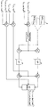
Figures 8 and 9 show the first topology of the controller in combination;
Figures 10 and 11 show the second topology of the controller in combination;
Figure 12 shows a third topology of the controller;
Figure 13 shows a fourth topology of the controller;
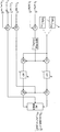
Figure 14 shows a fifth topology of the controller;
Figures 15 and 16 show the sixth topology of the controller in combination;
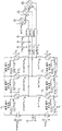
17 to 20 show a combination of the seventh topology of the controller;
Figure 21 shows the eighth topology of the controller;
Figures 22-27 show the ninth topology of the controller in combination;
28 shows in a simplified form the first simulation topology of the controller;
29 shows in a simplified form the second simulation topology of the controller;
30 shows in a schematic form the occurrence of a fault in one phase of an AC electrical network;
31 schematically illustrates the operation of the valve as a current limiter during the occurrence of a fault in one phase of an AC electrical network;
32 to 35 show simulation results based on the first and second simulation topologies shown in Figs. 28 and 29. Fig.
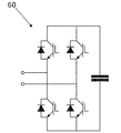
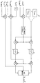
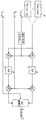
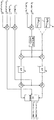
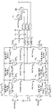
본 발명의 실시예에 따른 전압 소스 변환기가 도 1에 도시되어 있다.A voltage source converter according to an embodiment of the present invention is shown in FIG.
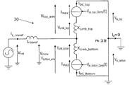
전압 소스 변환기(30)는 제1 및 제2 DC 단자(32, 34), 및 복수의 위상 림(36)을 포함한다. 간단화의 목적으로, 도 1은 단지 복수의 위상 림(36) 중 하나만을 도시하고 있지만, 다른 위상 림(36)은 도 1에 도시되어 있는 위상 림(36)에 구조가 동일하다는 것이 이해될 수 있을 것이다.The
각각의 위상 림(36)은 제1 및 제2 DC 단자(32, 34) 사이로 연장한다. 각각의 위상 림(36)은 제3 단자(42)에 의해 분리된 제1 및 제2 위상 림부(38, 40)를 포함한다. 도시되어 있는 실시예에서, 제1 위상 림부(38)는 제1 DC 단자(32)와 제3 단자(42) 사이로 연장하고, 제2 위상 림부(40)는 제2 DC 단자(34)와 제3 단자(42) 사이로 연장한다.Each phase rim 36 extends between the first and
사용시에, 제1 및 제2 DC 단자(32, 34)는 DC 전기 네트워크(44)의 양극 및 음극에 각각 접속되고, DC 전기 네트워크(44)의 양의 단자 및 음의 단자는 각각 VDC_top 및 VDC _bottom의 전압을 갖고, 각각의 위상 림(36)의 제3 단자(42)는 도 1에 변압기 인덕턴스로서 표현되어 있는 변압기(48)를 거쳐 다상 AC 전기 네트워크(46)의 각각의 위상에 접속된다.The first and
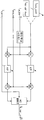
본 발명의 다른 실시예에서, 전압 소스 변환기는 전압 소스 변환기가 접속되어 있는 AC 전기 네트워크의 위상의 수에 정합하기 위해 단일의 위상 림 또는 상이한 복수의 위상 림을 가질 수도 있다는 것이 고려된다. 제1 및 제2 위상 림부(38, 40)는 각각 제1 및 제2 변환기 아암(38, 40)의 형태이다. 각각의 변환기 아암(38, 40)은 밸브(58)를 포함한다. 각각의 밸브(58)는 복수의 직렬 접속된 모듈(60)을 포함한다. 각각의 모듈(60)은 2개의 쌍의 스위칭 소자 및 캐패시터의 형태의 에너지 저장 디바이스를 포함한다. 각각의 모듈(60)에서, 스위칭 소자의 쌍은, 도 2에 도시되어 있는 바와 같이, 0, 음의 또는 양의 전압을 제공할 수 있고 2개의 방향에서 전류를 전도할 수 있는 4-상한 쌍극형 모듈(60)을 형성하기 위해 풀브리지 배열로 캐패시터와 병렬로 접속되어 있다.In another embodiment of the invention, it is contemplated that the voltage source transducer may have a single phase rim or a different plurality of phase rims to match the number of phases of the AC electrical network to which the voltage source transducer is connected. The first and second
본 발명의 다른 실시예에서, 각각의 모듈(60)은 0 또는 양의 전압을 제공할 수 있는 단방향성 전압 소스일 수도 있다는 것이 고려된다. 이러한 모듈(60)은 바람직하게는 2개의 방향에서 전류를 전도할 수 있는 데, 즉 각각의 모듈(60)은 2-상한 단극형 모듈(60)일 수도 있다. 예를 들어, 각각의 모듈(60)은, 도 3에 도시되어 있는 바와 같이, 0 또는 양의 전압을 제공할 수 있고 2개의 방향에서 전류를 전도할 수 있는 2-상한 단극형 모듈(60)을 형성하기 위해 하프 브리지 배열로 에너지 저장 디바이스와 병렬로 접속된 한 쌍의 스위칭 소자를 포함할 수도 있다.In another embodiment of the present invention, it is contemplated that each
본 발명의 또 다른 실시예에서, 각각의 밸브는 2-상한 단극형 모듈 및 4-상한 쌍극형 모듈의 조합을 포함할 수도 있다는 것이 고려된다.In another embodiment of the present invention, it is contemplated that each valve may comprise a combination of a two-high limit unipolar module and a four-high limit bipolar module.
각각의 모듈(60)의 각각의 스위칭 소자는 역병렬 다이오드와 병렬로 접속되어 있는 절연 게이트 쌍극 트랜지스터(Insulated Gate Bipolar Transistor: IGBT)의 형태의 반도체 디바이스에 의해 구성된다. 본 발명의 다른 실시예에서, 각각의 모듈(60)의 각각의 스위칭 소자는 게이트 턴오프 사이리스터, 전계 효과 트랜지스터, 주입 촉진형 게이트 트랜지스터, 통합 게이트 정류 사이리스터 또는 임의의 다른 자기 정류형 반도체 디바이스와 같은 상이한 스위칭 디바이스일 수도 있다는 것이 고려된다.Each switching element of each
본 발명의 다른 실시예에서, 캐패시터는 에너지를 저장하고 방출하는 것이 가능한 다른 에너지 저장 디바이스, 예를 들어 배터리로 대체될 수도 있다는 것이 고려된다.In another embodiment of the present invention, it is contemplated that the capacitor may be replaced by another energy storage device, e. G., A battery, which is capable of storing and emitting energy.
각각의 모듈(60)의 캐패시터는 스위칭 소자의 상태를 변경함으로써 대응 밸브(58)를 선택적으로 바이패스되거나 삽입된다. 이는 캐패시터를 통해 전류를 선택적으로 유도하거나 또는 전류가 캐패시터를 바이패스하게 하여, 각각의 모듈(60)이 0, 음의 또는 양의 전압을 제공하게 된다.The capacitors of each
각각의 모듈(60)의 캐패시터는 각각의 모듈(60) 내의 스위칭 소자의 쌍이 모듈(60) 내에 단락 회로를 형성하도록 구성될 때 바이패스되어, 단락이 캐패시터를 바이패스한다. 이는 밸브(58) 내의 전류가 단락 회로를 통과하고 캐패시터를 바이패스하게 하고, 따라서 모듈(60)은 0 전압을 제공하는 데, 즉 모듈(60)은 바이패스된 모드로 구성된다.The capacitors of each
각각의 모듈(60)의 캐패시터는 각각의 모듈(60) 내의 스위칭 소자의 쌍이 밸브(58) 내의 전류가 캐패시터 내외로 흐르게 할 때 밸브(58) 내에 삽입된다. 캐패시터는 이어서 0이 아닌 전압을 제공하기 위해 그 저장된 에너지를 충전하거나 방전하는 데, 즉 모듈(60)은 비-바이패스된 모드로 구성된다. 각각의 모듈(60)의 스위칭 소자의 풀브리지 배열은 스위칭 소자의 구성이 어느 한 방향에서 캐패시터 내외로 전류가 흐르게 하도록 허용하고, 따라서 각각의 모듈(60)은 비-바이패스된 모드에서 음의 또는 양의 전압을 제공하도록 구성될 수 있다.The capacitors of each
이 방식으로, 각각의 모듈(60)은 전압 소스를 선택적으로 제공하도록 동작 가능하다.In this manner, each
그 자신의 전압을 각각 제공하는 다수의 모듈(60)의 캐패시터의 각각의 밸브(58) 내로의 삽입을 거쳐, 그 개별 모듈(60)의 각각으로부터 이용 가능한 전압보다 더 높은 결합 전압(combined voltage)을 각각의 밸브(58)를 가로질러 축적하는(build up) 것이 가능하다.Through the insertion into the
전압 소스 변환기(30)는 각각의 모듈(60) 내의 스위칭 소자의 스위칭의 제어를 통해 각각의 밸브(58)를 동작하도록 프로그램된 제어기(62)를 더 포함한다. 더 구체적으로, 제어기(62)는 그를 가로질러 밸브 전압(Vvalve _top, Vvalve _bottom)을 발생하기 위해 각각의 밸브(58)를 동작하기 위한 각각의 전압 오더 신호(Vbe _top, Vbe _bottom)를 발생한다. 각각의 전압 오더 신호(Vbe _top, Vbe _bottom)는 각각의 밸브 전압(Vvalve _top, Vvalve_bottom)의 이미지이고, DC 전압 성분 및 AC 전압 성분으로 이루어진다.The
도 1의 전압 소스 변환기(30)의 동작이 도 4 내지 도 35를 참조하여 이하와 같이 설명된다.The operation of the
본 명세서에 있어서, 전압 소스 변환기(30)의 동작은 주로 그 복수의 위상 림(36) 중 하나를 참조하여 설명된다. 전압 소스 변환기(30)의 복수의 위상 림(36) 중 하나의 설명된 동작은 각각의 다른 위상 림(36)의 동작에 필요한 변경을 가하여 적용된다는 것이 이해될 수 있을 것이다.In this specification, the operation of the
전압 소스 변환 동작을 수행하기 위한 전압 소스 변환기(30)의 제어 중에, 제어기(62)는 전압 소스를 선택적으로 제공하고 이에 의해 각각의 밸브(58)의 밸브 전압(Vvalve_top, Vvalve _bottom)을 수정하기 위해 각각의 모듈(60)의 스위칭 소자의 스위칭을 제어한다. 이는 AC 및 DC 전기 네트워크(46, 44)의 상호접속을 허용하고 이에 의해 AC 및 DC 전기 네트워크(46, 44) 사이의 전력의 전달을 가능하게 하기 위해 제3 단자(42)에서 AC 전압의 구성에 대한 제어를 가능하게 한다.The control of the voltage source converter (30) for performing a voltage source switching operation, the
본 명세서에 있어서, 각각의 밸브(58) 내의 모듈(60)의 캐패시터의 전압은 균형화되는 것으로 가정되고, 변환기 아암(38, 40)마다 무한개의 모듈(60)이 존재하고, 각각의 모듈(60) 내의 스위칭 소자의 스위칭 주파수는 제3 단자(42)에서 완벽한 정현파 AC 전압을 제공하도록 무한대인 것으로 가정된다. 이와 같이, 각각의 변환기 아암(38, 40)은 도 1에 도시되어 있는 바와 같이, 리액터와 직렬로 등가 전압 소스에 의해 표현될 수 있다.The voltage of the capacitor of
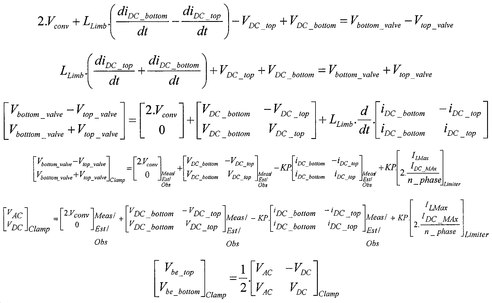
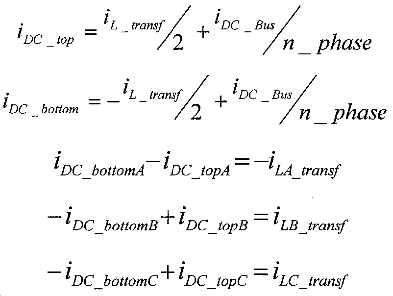
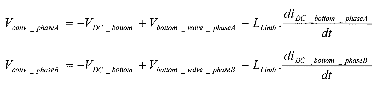
각각의 위상 림(36)의 전기 특성은 이하의 식에 의해 제공된다:The electrical properties of each phase rim 36 are provided by the following equation:
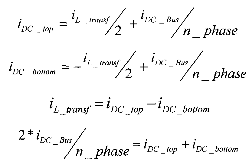
여기서, iDC_top은 제1 변환기 아암(38) 내에서 흐르는 전류이고;Where i DC_top is the current flowing in the
iDC_bottom은 제2 변환기 아암(40) 내에서 흐르는 전류이고;i DC_bottom is the current flowing in the
iL_transf는 변압기(48) 내에서 흐르는 전류이고;i L_transf is the current flowing in
iDC_Bus는 제1 및 제2 DC 단자(32, 34) 내에서 흐르는 전류이고;i DC_Bus is the current flowing in the first and
n_phase는 위상 림(36)의 수이고;n_phase is the number of
Vnet은 AC 전기 네트워크(46)의 AC 전압이고;V net is the AC voltage of the AC
MTransfo_Model은 변압기(48)의 권선비이고;M Transfo_Model is the turns ratio of the
Vtransf는 변압기(48)를 가로지르는 AC 전압이고;V transf is the AC voltage across the
Vconv는 제3 단자(42)에서의 AC 전압이고[즉, 전압 소스 변환기(30)와 변압기(48) 사이의 전압];V conv is the AC voltage at the third terminal 42 (i.e., the voltage between the
Ltransf는 변압기(48)의 인덕턴스이고;L transf is the inductance of
RLimb_top은 제1 변환기 아암(38)의 저항이고;R Limb_top is the resistance of the
RLimb_bottom은 제2 변환기 아암(40)의 저항이고;R Limb_bottom is the resistance of the
LLimb은 각각의 변환기 아암(38, 40)의 인덕턴스이고;L Limb is the inductance of each
VDC_top은 제1 DC 단자(32)에서의 DC 전압이고;V DC_top is the DC voltage at the
VDC_bottom은 제2 DC 단자(34)에서의 DC 전압이다.And V DC_bottom is the DC voltage at the
전압 소스 변환 동작 중에, 각각의 변환기 아암(38, 40) 내에서 흐르는 전류는 연계된 전기 네트워크(44, 46) 내의 고장 또는 장애의 결과로서 그 정상 동작 레벨 또는 범위를 넘어 증가할 수도 있고, 따라서 각각의 변환기 아암(38, 40) 내에 과전류를 야기한다.During a voltage source conversion operation, the current flowing in each
도 4는 AC 전기 네트워크(46) 내의 고장의 발생을 개략 형태로 도시하고 있다. 도 5는 DC 전기 네트워크(44)의 각각의 극에서 고장의 발생을 개략 형태로 도시하고 있다. 고장은 DC 전기 네트워크(44)의 극 중 단지 하나에서만 발생할 수도 있다는 것이 이해될 수 있을 것이다.4 shows in a schematic form the occurrence of a fault in the AC
각각의 변환기 아암(38, 40) 내의 과전류의 가능성은 기대 수명을 감소시키고, 변환기 아암 구성요소 뿐만 아니라 각각의 변환기 아암(38, 40)에 접속된 다른 장비(예를 들어, 송전 케이블)의 파괴의 위험을 증가시킨다. 게다가, 각각의 변환기 아암(38, 40) 내의 과전류의 존재는 변환기 아암 구성요소의 온도를 증가시키고 이에 의해 이들의 성능에 악영향을 미칠 수 있다.The likelihood of overcurrent in each
연계된 전기 네트워크(44, 46) 내의 고장 또는 장애의 발생 중에, 제어기(62)는 각각의 변환기 아암(38, 40) 내에 흐르는 선택된 전류, 위상 림(36) 내로 흐르는 선택된 전류 및/또는 복수의 위상 림(36) 중 2개 또는 3개 사이에서 순환하는 선택된 전류를 고정 또는 가변 전류 임계치 이하로 제한하기 위한 전류 제한기로서 각각의 밸브(58)를 동작한다. 더 구체적으로, 제어기(62)는 제3 단자(42)와 제1 및 제2 단자(32, 34)의 대응하는 것 중 하나 또는 모두에서 전압을 클램핑하도록 각각의 밸브(58)를 동작하기 위해, 클램핑 전압 오더 신호(Vbe _top_Clamp, Vbe_bottom_Clamp)의 AC 전압 성분을 클램핑함으로써, 각각의 클램핑 전압 오더 신호(Vbe_top_Clamp, Vbe _bottom_Clamp)를 발생한다. 각각의 클램핑 전압 오더 신호(Vbe _top_Clamp, Vbe_bottom_Clamp)에 따라 각각의 밸브(58)를 동작하는 것은, AC 및 DC 전기 네트워크(46, 44) 각각 내의 고장의 발생 중에 전류 제한기로서 밸브(58)의 동작을 개략적으로 도시하고 있는 도 6 및 도 7에 도시되어 있는 바와 같이, 각각의 밸브(58)가 선택된 전류를 제한하기 위해 등가의 전류 소스를 형성하게 한다.During the occurrence of a fault or fault in the associated
각각의 클램핑 전압 오더 신호(Vbe _top_Clamp, Vbe _bottom_Clamp)의 값은 전압 소스 변환 동작 전 또는 중에 규정되고, 계산되고, 시뮬레이팅되고, 추정되거나 또는 관찰에 기초할 수도 있는 고정 또는 가변 전류 임계치의 값에 의존한다.Each clamping value of the voltage order signal (V be _top_Clamp, V be _bottom_Clamp) is defined in the across-the-line source switching operation or, is calculated, simulated and, estimate or may be based on observing a fixed or a variable current threshold which Depending on the value.
제어기(62)는 전류 임계치에 도달하거나 초과하는 선택된 전류에 응답하여 전류 제한기로서 각각의 밸브(58)를 동작하도록 프로그램될 수도 있다. 전류 임계치에 도달하거나 초과하는 선택된 전류의 이벤트에 응답하도록 제어기(62)를 구성함으로써, 요구가 발생할 때 전류 제한기로서 각각의 밸브(58)를 자동으로 동작하는 것이 가능해진다. 선택된 전류가 전류 임계치에 도달하거나 초과하였는지 여부를 결정하기 위해, 선택된 전류는 각각의 밸브(58), 각각의 변환기 아암(38, 40), 전압 소스 변환기(30) 또는 전압 소스 변환기(30)에 접속된 다른 장비를 거쳐 직접 또는 간접 측정되고, 추정되거나, 관찰될 수도 있다.The
전압 소스 변환기(30) 내의 제어기(62)의 포함은 각각의 변환기 아암(38, 40) 내에 흐르는 전류의 선택적 제한을 가능하게 하여 각각의 변환기 아암(38, 40) 내에 흐르는 전류가 고정 또는 가변 전류 임계치 이하로 제한되는 것을 보장한다. 이는 고장 또는 장애의 발생으로부터 발생하는 높은 고장 전류가 각각의 변환기 아암(38, 40) 내에 흐르는 것을 방지한다. 이는 변환기 아암 구성요소 및 각각의 변환기 아암(38, 40)에 접속된 다른 장비의 기대 수명 및 신뢰성을 향상시킬 뿐만 아니라, 또한 이들의 성능에 악영향을 미칠 수 있는 변환기 아암 구성요소의 온도의 증가를 방지한다.The inclusion of the
게다가, 각각의 밸브(58)가 각각의 변환기 아암(38, 40)의 부분을 형성하기 때문에, 전류 제한기로서의 밸브(58)의 사용은 각각의 변환기 아암(38, 40) 내에서 흐르는 전류를 제한하는 요구에 대한 고속 응답을 가능하게 한다.In addition, because each
더욱이, 전압 소스 변환기(30) 내의 제어기(62)의 포함은 각각의 변환기 아암(38, 40) 내에서 흐르는 전류의 선택적 제한을 가능하게 하기 위한 개별 전류 제한 장비의 설치를 위한 요구를 제거하여, 따라서 전압 소스 변환기(30)의 비용, 크기 및 중량의 최적화를 허용한다.Furthermore, the inclusion of the
이 방식으로, 전압 소스 변환기(30) 내의 제어기(62)의 포함은 고장 및 장애 순간 보상 능력을 전압 소스 변환기(30)에 제공한다. 이는 전압 소스 변환기(30)가 특정 고장 및 장애 조건[AC 전기 네트워크(46)의 1개의 위상에서의 고장 또는 2개의 위상에서의 고장과 같은] 하에서 고장 또는 장애 기간 전체에 걸쳐 전압 소스 변환 동작을 수행하게 하고, 다른 고장 및 장애 조건[AC 전기 네트워크(46)의 모든 3개의 위상에서의 고장과 같은] 하에서 정상 동작 상태로의 전압 소스 변환기(30)의 고속 복구를 가능하게 한다.In this manner, the inclusion of the
고장 또는 장애의 발생 중에 전류 제한기로서 밸브(58)를 동작하는 능력은, 각각의 밸브(58)가 전류 제한기로서 동작될 때 제3 단자(42)와 제1 및 제2 단자(32, 34) 중 대응하는 것 사이에 전력을 전달하기 위해 변환기 아암(38, 40)을 동작하도록 제어기(62)가 프로그램되게 한다. 이와 같이, 고장 또는 장애의 발생 중에 전류 제한기로서 밸브(58)를 동작하는 능력은 전압 소스 변환기(30)가 고장 또는 장애 중에 전압 소스 변환 동작을 계속 수행하는 것을 허용한다. 그렇지 않으면, 각각의 변환기 아암(38, 40) 내에 흐르는 전류를 제한하기 위해 고장 또는 장애 중에 변환기 아암(38, 40)을 차단할 필요가 있고, 따라서 전압 소스 변환기(30)가 전압 소스 변환 동작을 수행하는 것을 방지하고 이에 의해 전압 소스 변환기(30)의 작동에 의존하는 최종 사용자를 불편하게 한다.The ability to operate the
고장 또는 장애의 발생 중에 전류 제한기로서 밸브(58)를 동작하는 능력은 또한 고장 또는 장애 중에 각각의 변환기 아암(38, 40) 내에서 흐르는 전류의 능동 제어를 위한 요구를 제거한다. 각각의 변환기 아암(38, 40) 내에서 흐르는 전류의 이러한 능동 제어는 실행이 어려울 수 있고, 복잡한 제어 알고리즘의 사용을 필요로 할 것이다.The ability to operate the
더욱이, 고장 또는 장애의 발생 중에 전류 제한기로서 밸브(58)를 동작하는 능력은 전압 소스 변환 동작 중에 발생하는 고장 또는 장애의 가능성을 고려하기 위해 변환기 아암 구성요소의 기대 수명을 감소시켜야 할 필요성을 감소시킨다.Moreover, the ability to operate the
제어기(62)는 전류 제한기로서 각각의 밸브(58)를 동작하는 것을 가능하게 하기 위해 다양한 방식으로 프로그램될 수도 있는 데, 그 예가 이하와 같이 설명되어 있다.The
이하의 예의 각각에서, 적용 가능하면, 각각의 이득값(KP, KC)은 임의의 고정값 또는 임의의 동적값일 수 있다. 예를 들어, 동적값은 측정된 전류와 전류 수요 사이의 에러의 함수일 수도 있고, 그리고/또는 실시간의 LLimb의 함수, 및/또는 AC 전기 네트워크(46)의 주파수의 함수일 수 있다. 예를 들어, KP = KC = 2·π·f·LLimb이고, 여기서 f는 AC 전기 네트워크(46)의 기본 주파수이다.In each of the following examples, where applicable, each gain value (KP, KC) may be any fixed value or any dynamic value. For example, the dynamic value may be a function of the error between the measured current and the current demand, and / or may be a function of the real-time L Limb , and / or the frequency of the AC
예 1Example 1
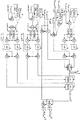
도 8은 이하의 식에 따라 위상 림(36) 내로 흐르는 전류(iL_ transf)를 전류 임계치(ILMax) 이하로 제한하도록 요구되는 제3 단자(42)에서의 클램핑 전압의 값(VAC_Clamp)을 발생하도록 프로그램되는 제어기(62)의 제1 토폴로지를 도시하고 있다.8 is the value of the clamping voltage at the


여기서 RLimb_top 및 RLimb_bottom은 0인 것으로 고려되고;Where R Limb_top and R Limb_bottom are considered to be zero;
ILMax는 변압기(48) 내에서 흐르는 전류에 대한 전류 임계치이고;I LMax is the current threshold for current flowing in
VAC _Clamp는 위상 림(36) 내로 흐르는 전류(iL_ transf)를 전류 임계치(ILMax) 이하로 제한하도록 요구되는 제3 단자(42)에서의 클램핑 전압의 값이다.V AC _Clamp is the value of the clamping voltage at a current
이 방식으로, 도 8에 도시되어 있는 바와 같이, 제어기(62)는 위상 림(36) 내로 흐르는 전류(iL_ transf)를 전류 임계치(ILMax) 이하로 제한하도록 요구되는 제3 단자(42)에서의 클램핑 전압값(VAC_Clamp)을 발생한다. 도 9에 도시되어 있는 바와 같이, 제어기(62)는 제3 단자(42)에서 AC 전압을 클램핑 전압값(VAC_Clamp)에서 클램핑하도록 각각의 밸브(58)를 동작하기 위해 각각의 클램핑 전압 오더 신호(Vbe _top_Clamp, Vbe_bottom_Clamp)를 발생하도록 프로그램된다. 이 방식으로, 제어기는 위상 림(36) 내로 흐르는 선택된 전류(iL_ transf)를 전류 임계치(ILMax) 이하로 제한하기 위한 전류 제한기로서 각각의 밸브(58)를 동작하도록 프로그램된다.In this way, as shown in Figure 8,
클램핑 전압값(VAC_Clamp)의 발생 중에 AC 전기 네트워크(46)의 AC 전압(Vnet)을 프로세싱하는 대신에, 제어기는 대신에 도 9에 도시되어 있는 바와 같이, 전류 제한기로서 각각의 밸브(58)를 동작하기 위해 AC 전기 네트워크(46)의 AC 전압(Vnet)과 하나 이상의 고조파 전압 성분의 조합을 프로세싱할 수도 있다는 것이 이해될 수 있을 것이다.Instead of processing the AC voltage (V net ) of the AC
예 2Example 2
도 10 및 도 11은 이하의 식에 따라 위상 림(36) 내로 흐르는 전류(iL_ transf)를 전류 임계치(ILMax) 이하로 제한하도록 요구되는 제3 단자(42)에서의 클램핑 전압의 값(VAC _Clamp)을 발생하도록 프로그램되는 제어기(62)의 제2 토폴로지를 조합하여 도시하고 있다.10 and 11 is the value of the clamping voltage at the

재차, RLimb_top 및 RLimb_bottom은 0인 것으로 고려된다.Again, R Limb_top and R Limb_bottom are considered to be zero.
도 10의 제2 토폴로지는, 제어기(62)가 AC 전기 네트워크(46)의 AC 전압(Vnet) 대신에, 제3 단자(42)에서 AC 전압(Vconv)을 프로세싱함으로써 클램핑 전압값(VAC_Clamp)을 발생하도록 프로그램되는 점에서, 도 8의 제1 토폴로지와는 상이하다.The second topology of Figure 10 shows that the
도 11에 도시되어 있는 바와 같이, 제어기(62)는 제3 단자(42)에서 전압을 클램핑 전압값(VAC_Clamp)에서 클램핑하도록 각각의 밸브(58)를 동작하기 위해 각각의 클램핑 전압 오더 신호(Vbe _top_Clamp, Vbe _bottom_Clamp)를 발생하도록 프로그램된다. 이 방식으로, 제어기는 위상 림(36) 내로 흐르는 선택된 전류(iL_ transf)를 전류 임계치(ILMax) 이하로 제한하기 위한 전류 제한기로서 각각의 밸브(58)를 동작하도록 프로그램된다.11, the
예 3Example 3
도 12는 이하의 식에 따라 위상 림(36) 내로 흐르는 전류를 전류 임계치 이하로 제한하도록 요구되는 제1 및 제2 DC 단자(32, 34)를 가로지르는 클램핑 전압의 값(VDC _Clamp)을 발생하도록 프로그램되는 제어기(62)의 제3 토폴로지를 도시하고 있다.12 shows the value (V DC - Clamp ) of the clamping voltage across the first and

여기서, ILMax는 변압기(48) 내에서 흐르는 전류에 대한 전류 임계치이다.Where I LMax is the current threshold for the current flowing in the
이 방식으로, 도 12에 도시되어 있는 바와 같이, 제어기(62)는 위상 림(36) 내로 흐르는 전류를 전류 임계치(ILMax) 이하로 제한하도록 요구되는 제1 및 제2 DC 단자(32, 34)를 가로지르는 클램핑 전압값(VDC_Clamp)을 발생한다. 제어기(62)는 제1 및 제2 DC 단자(32, 34)를 가로지르는 DC 전압을 클램핑 전압값(VDC_Clamp)에서 클램핑하도록 각각의 밸브(58)를 동작하기 위해 각각의 클램핑 전압 오더 신호(Vbe_top_Clamp, Vbe _bottom_Clamp)를 발생하도록 프로그램된다. 이 방식으로, 제어기는 위상 림(36) 내로 흐르는 선택된 전류를 전류 임계치(ILMax) 이하로 제한하기 위한 전류 제한기로서 각각의 밸브(58)를 동작하도록 프로그램된다.12, the
예 4Example 4
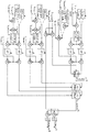
도 13은 이하의 식에 따라 위상 림(36) 내로 흐르는 전류(iL_ transf) 및 위상 림(36) 내에서 흐르는 전류를 각각의 전류 임계치(ILMax, 2*IDC_Max/n_phase) 이하로 제한하도록 요구되는 제3 단자(42)에서의 그리고 제1 및 제2 DC 단자(32, 34)를 가로지르는 클램핑 전압의 값(VAC _Clamp, VDC _Clamp)을 발생하도록 프로그램되는 제어기(62)의 제4 토폴로지를 도시하고 있다.Figure 13 limits the current flowing in the current (i L_ transf) and phase rim 36 flowing into the phase rim 36 according to the following formula below a respective current threshold (I LMax, 2 * I DC_Max / n_phase) (V AC - Clamp , V DC - Clamp ) across the first and
제어기(62)의 제4 토폴로지는 도 9에 도시되어 있는 제어기(62)의 제1 토폴로지와 도 12에 도시되어 있는 제어기(62)의 제3 토폴로지의 조합이다.The fourth topology of the
이 방식으로, 도 13에 도시되어 있는 바와 같이, 제어기(62)는 위상 림(36) 내로 흐르는 전류(iL_ transf) 및 위상 림(36) 내에서 흐르는 전류를 각각의 전류 임계치(ILMax, 2*IDC_Max/n_phase) 이하로 제한하도록 요구되는 제3 단자(42)에서의 그리고 제1 및 제2 DC 단자(32, 34)를 가로지르는 AC 및 DC 클램핑 전압(VAC _Clamp, VDC _Clamp)을 발생한다. 제어기(62)는 제3 단자(42)에서의 AC 전압을 AC 클램핑 전압값(VAC_Clamp)에서 클램핑하도록 그리고 제3 단자(42)에서의 DC 전압을 DC 클램핑 전압값(VDC_Clamp)에서 클램핑하도록 각각의 밸브(58)를 동작하기 위해 각각의 클램핑 전압 오더 신호(Vbe _top_Clamp, Vbe _bottom_Clamp)를 발생하도록 프로그램된다. 이 방식으로, 제어기는 위상 림(36) 내로 흐르는 전류(iL_ transf) 및 위상 림(36) 내에서 흐르는 전류를 각각의 전류 임계치(ILMax, 2*IDC_Max/n_phase) 이하로 제한하기 위한 전류 제한기로서 각각의 밸브(58)를 동작하도록 프로그램된다.13, the
예 5Example 5
도 14는 이하의 식에 따라 위상 림(36) 내로 흐르는 전류(iL_ transf) 및 위상 림(36) 내에서 흐르는 전류를 각각의 전류 임계치(ILMax, 2*IDC_Max/n_phase) 이하로 제한하도록 요구되는 제3 단자(42)에서의 그리고 제1 및 제2 DC 단자(32, 34)를 가로지르는 클램핑 전압의 값(VAC _Clamp, VDC _Clamp)을 발생하도록 프로그램되는 제어기(62)의 제5 토폴로지를 도시하고 있다.14 limits the current flowing in the current (i L_ transf) and phase rim 36 flowing into the phase rim 36 according to the following formula below a respective current threshold (I LMax, 2 * I DC_Max / n_phase) (V AC - Clamp , V DC - Clamp ) across the first and

도 14의 제5 토폴로지는, 제어기(62)의 제5 토폴로지가 도 11에 도시되어 있는 제어기(62)의 제2 토폴로지와 도 2에 도시되어 있는 제어기(62)의 제3 토폴로지의 조합인 점에서, 도 13의 제4 토폴로지와는 상이하다. 따라서, 제어기(62)는 AC 전기 네트워크(46)의 AC 전압(Vnet) 대신에, 제3 단자(42)에서 AC 전압(Vconv)을 프로세싱함으로써 클램핑 전압값(VAC_Clamp, VDC_Clamp)을 발생하도록 프로그램된다.14 is that the fifth topology of the
이 방식으로, 도 14에 도시되어 있는 바와 같이, 제어기(62)는 위상 림(36) 내로 흐르는 전류(iL_ transf) 및 위상 림(36) 내에서 흐르는 전류를 각각의 전류 임계치(ILMax, 2*IDC_Max/n_phase) 이하로 제한하도록 요구되는 제3 단자(42)에서의 그리고 제1 및 제2 DC 단자(32, 34)를 가로지르는 AC 및 DC 클램핑 전압(VAC _Clamp, VDC _Clamp)을 발생한다. 제어기(62)는 제3 단자(42)에서의 AC 전압을 AC 클램핑 전압값(VAC_Clamp)에서 클램핑하도록 그리고 제3 단자(42)에서의 DC 전압을 DC 클램핑 전압값(VDC_Clamp)에서 클램핑하도록 각각의 밸브(58)를 동작하기 위해 각각의 클램핑 전압 오더 신호(Vbe _top_Clamp, Vbe _bottom_Clamp)를 발생하도록 프로그램된다. 이 방식으로, 제어기는 위상 림(36) 내로 흐르는 전류(iL_ transf) 및 위상 림(36) 내에서 흐르는 전류를 각각의 전류 임계치(ILMax, 2*IDC_Max/n_phase) 이하로 제한하기 위한 전류 제한기로서 각각의 밸브(58)를 동작하도록 프로그램된다.14, the
예 6Example 6
도 15 및 도 16은 이하의 식에 따라 각각의 변환기 아암(38, 40) 내에서 흐르는 각각의 전류(iDC_top, iDC_bottom)를 전류 임계치(IMAX_ IGBT) 이하로 제한하도록 제3 단자(42)에서의 클램핑 전압의 값(VAC _Clamp)을 발생하도록 프로그램되는 제어기(62)의 제6 토폴로지를 조합하여 도시하고 있다.15 and 16 a third terminal (42 to limit the respective current (i DC_top, i DC_bottom) flowing in each of the transducer arm (38, 40) according to the following formula below a current threshold (I MAX_ IGBT) (V AC - Clamp) of the clamping voltage at the second node (V AC - Clamp ).

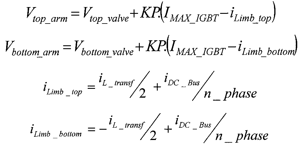
이 방식으로, 도 15 및 도 16에 도시되어 있는 바와 같이, 제어기(62)는 각각의 변환기 아암(38, 40) 내에서 흐르는 각각의 전류(iDC_top, iDC_bottom)를 전류 임계치(IMAX_IGBT) 이하로 제한하도록 요구되는 제3 단자(42)에서의 클램핑 전압값(VAC_Clamp)을 발생한다. 제어기(62)는 제3 단자(42)에서의 AC 전압을 AC 클램핑 전압값(VAC_Clamp)에서 클램핑하도록 각각의 밸브(58)를 동작하기 위해 각각의 클램핑 전압 오더 신호(Vbe _top_Clamp, Vbe _bottom_Clamp)를 발생하도록 프로그램된다. 이 방식으로, 제어기는 각각의 변환기 아암(38, 40) 내에서 흐르는 각각의 전류(iDC_top, iDC_bottom)를 전류 임계치(IMAX_ IGBT) 이하로 제한하기 위한 전류 제한기로서 각각의 밸브(58)를 동작하도록 프로그램된다.In this way, as shown in Figs. 15 and 16, the
예 7Example 7
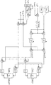
도 17 내지 도 20은 이하의 식에 따라 복수의 위상 림(36) 사이에서 순환하는 전류를 전류 임계치(Delta_ILMax) 이하로 제한하도록 요구되는 제3 단자(42)에서의 각각의 클램핑 전압의 값(VAC _Clamp_ phaseA, VAC _Clamp_ phaseB, VAC _Clamp_ phaseC)을 발생하도록 프로그램되는 제어기(62)의 제7 토폴로지를 조합하여 도시하고 있다.17-20 illustrate the values of the respective clamping voltages at the third terminal 42 required to limit the current circulating between the plurality of


여기서, VAC _Clamp_ phaseA _up 및 VAC _Clamp_ phaseA _down은 위상 림(36) 중 제1 위상 림과 관련하여 제3 단자(42)에서 AC 클램핑 전압(VAC_Clamp_phaseA)을 함께 규정하고;Here, V AC and V AC _Clamp_ phaseA _up _Clamp_ phaseA _down and is defined with the AC clamping voltage (V AC_Clamp_phaseA) in the third terminal 42 with respect to the first phase of the rim phase-rim (36);
VAC _Clamp_ phaseB _up 및 VAC _Clamp_ phaseB _down은 위상 림(36) 중 제2 위상 림과 관련하여 제3 단자(42)에서 AC 클램핑 전압(VAC_Clamp_phaseB)을 함께 규정하고;V AC and V AC _Clamp_ phaseB _up _Clamp_ phaseB _down and is defined with the AC clamping voltage (V AC_Clamp_phaseB) in the third terminal 42 with respect to the second phase of rim phase Figure 36;
VAC _Clamp_ phaseC _up 및 VAC _Clamp_ phaseC _down은 위상 림(36) 중 제3 위상 림과 관련하여 제3 단자(42)에서 AC 클램핑 전압(VAC_Clamp_phaseC)을 함께 규정하고;V AC and V AC _Clamp_ phaseC _up _Clamp_ phaseC _down and is defined with the AC clamping voltage (V AC_Clamp_phaseC) in the third terminal 42 with respect to the third phase of the rim phase-rim (36);
VAC _ int _ phaseA, VAC _ int _ phaseB 및 VAC _ int _ phaseC는 각각의 위상 림(36) 내에서 순환하는 교류이다.V AC _ int _ phase A , V AC _ int _ phase B, and V AC _ int _ phase C are alternating currents within each phase rim 36.
이 방식으로, 도 17 내지 도 20에 도시되어 있는 바와 같이, 제어기(62)는 복수의 위상 림(36) 사이에서 순환하는 전류를 전류 임계치(Delta_ILMax) 이하로 제한하도록 요구되는 각각의 제3 단자(42)에서 클램핑 전압값(VAC_Clamp)을 발생한다. 도 18 내지 도 20에 도시되어 있는 바와 같이, 제어기(62)는 각각의 제3 단자(42)에서의 AC 전압을 클램핑 전압값(VAC_Clamp)에서 클램핑하도록 각각의 밸브(58)를 동작하기 위해 각각의 클램핑 전압 오더 신호(Vbe _top_Clamp, Vbe _bottom_Clamp)를 발생하도록 프로그램된다. 이 방식으로, 제어기는 복수의 위상 림(36) 사이에서 순환하는 선택된 전류를 전류 임계치(Delta_ILMax) 이하로 제한하기 위한 전류 제한기로서 각각의 밸브(58)를 동작하도록 프로그램된다.In this way, as shown in Figures 17 to 20, the
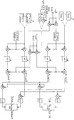
예 8Example 8
도 21은 이하의 식에 따라 복수의 위상 림(36) 사이에서 순환하는 전류를 전류 임계치(Delta_ILMax) 이하로 제한하도록 요구되는 제3 단자(42)에서의 그리고 제1 및 제2 DC 단자(32, 34)를 가로지르는 각각의 클램핑 전압의 값(VAC _Clamp_ phaseA, VDC_Clamp_phaseA)을 발생하도록 프로그램되는 제어기(62)의 제8 토폴로지를 조합하여 도시하고 있다.21 is a graph showing the relationship between the current flowing between the first and

예 9Example 9
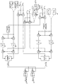
도 22 내지 도 27은 이하의 식에 따라 복수의 위상 림(36) 사이에서 순환하는 전류를 전류 임계치(Delta_ILMax) 이하로 제한하도록 요구되는 제3 단자(42)에서의 각각의 클램핑 전압의 값을 발생하도록 프로그램되는 제어기(62)의 제9 토폴로지를 조합하여 도시하고 있다.22-27 show the values of the respective clamping voltages at the third terminal 42 required to limit the current circulating between the plurality of

이 방식으로, 도 22 내지 도 27에 도시되어 있는 바와 같이, 제어기(62)는 복수의 위상 림(36) 사이에서 순환하는 전류를 전류 임계치(Delta_ILMax) 이하로 제한하도록 요구되는 제3 단자(42)에서의 클램핑 전압값을 발생한다. 제어기(62)는 제3 단자(42)에서 AC 전압을 각각의 클램핑 전압값에서 클램핑하도록 위상 림(36) 내에서 각각의 밸브(58)를 동작하기 위해 각각의 클램핑 전압 오더 신호(Vbe _top_Clamp, Vbe_bottom_Clamp)를 발생하도록 프로그램된다. 이 방식으로, 제어기는 복수의 위상 림(36) 사이에서 순환하는 선택된 전류를 전류 임계치(Delta_ILMax) 이하로 제한하기 위한 전류 제한기로서 각각의 밸브(58)를 동작하도록 프로그램된다.In this manner, as shown in Figures 22-27, the
시뮬레이션 결과Simulation result
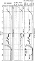
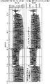
도 28은 AC 전기 네트워크(46)의 일 위상에서 고장의 발생 중에, 위상 림(36) 내로 흐르는 전류(iL_ transf)를 전류 임계치(ILMax) 이하로 제한하도록 요구되는 제3 단자(42)에서의 클램핑 오더값(VAC_Clamp)의 발생을 시뮬레이팅하는 데 사용된 제어기(62)의 제1 시뮬레이션 토폴로지를 개략 형태로 도시하고 있다. 제어기(62)의 제1 시뮬레이션 토폴로지는 도 10에 도시되어 있는 제어기(62)의 제2 토폴로지에 기초한다. 제1 시뮬레이션 토폴로지에서, 제어기(62)는 제3 단자(42)에서 AC 전압(Vconv)을 프로세싱함으로써 클램핑 전압값(VAC_Clamp)을 발생하도록 프로그램된다.28 is a
도 29는 AC 전기 네트워크(46)의 일 위상에서 고장의 발생 중에, 위상 림(36) 내로 흐르는 전류(iL_ transf)를 전류 임계치(ILMax) 이하로 제한하도록 요구되는 제3 단자(42)에서의 그리고 제1 및 제2 DC 단자(32, 34)를 가로지르는 클램핑 오더값(VAC_Clamp, VDC_Clamp)의 발생을 시뮬레이팅하는 데 사용된 제어기(62)의 제2 시뮬레이션 토폴로지를 개략 형태로 도시하고 있다. 제어기(62)의 제2 시뮬레이션 토폴로지는 도 14에 도시되어 있는 제어기(62)의 제5 토폴로지에 기초한다. 제2 시뮬레이션 토폴로지에서, 제어기(62)는 제3 단자(42)에서 AC 전압(Vconv)을 프로세싱함으로써 클램핑 전압값(VAC_Clamp)을 발생하도록 프로그램된다.29 is the third required during the occurrence of a failure in one phase of the AC electricity network (46), so as to limit the current (i L_ transf) flowing into the phase Figure 36 below the current threshold (I LMax) terminal 42 in and a second simulated topology of the first and second DC terminals (32,34), the
도 30은 AC 전기 네트워크(46)의 일 위상에서 고장의 발생을 개략 형태로 도시하고 있다. 도 31은 AC 전기 네트워크(46)의 일 위상에서 고장의 발생 중에, 위상 림(36) 내로 흐르는 전류(iL_ transf)를 전류 임계치(ILMax) 이하로 제한하기 위한 전류 제한기로서 대응 밸브(58)의 동작을 개략 형태로 도시하고 있다.30 shows in a schematic form the occurrence of a fault in one phase of the AC
시뮬레이션에서, 제1 및 제2 DC 단자(32, 34) 내에서 흐르는 전류(IDC_Max)는 고장 중에 공칭값으로 유지된다.In the simulation, the current (I DC - Max ) flowing in the first and
도 32 내지 도 35는 전류 제한기로서 대응 밸브(58)의 동작이 있는 그리고 동작이 없는 AC 전기 네트워크(46)의 일 위상에서 고장의 발생 중에 전압 소스 변환기(30)의 위상 림(36) 내에서 흐르는 전류의 거동을 비교하고 있다.Figures 32-35 illustrate the operation of the
도 32 내지 도 35에서의 시뮬레이션 결과는 HVDC 점대점 구성으로 적용될 때 도 1의 전압 소스 변환기(30)의 시뮬레이션에 기초한다. 시뮬레이션에서, AC 및 DC 전기 네트워크(44, 46) 사이의 전력 흐름은 720 MW이고, DC 단자(32, 34)를 가로지르는 DC 전압(VDC)은 600 kV이고, DC 전기 네트워크(44) 내에서 흐르는 전류(IDC_Bus)는 1200 A이다. 고장은 접지로의 단상 고장의 형태이고, 1초 동안 AC 전기 네트워크(24)에 인가된다.The simulation results in Figures 32 to 35 are based on simulations of the
도 32는 밸브(58)가 AC 전기 네트워크(46)의 일 위상에서 고장의 발생 중에 위상 림(36) 내로 흐르는 전류(iL_ transf)를 전류 임계치(ILMax) 이하로 제한하기 위한 전류 제한기로서 동작될 때, 전압 소스 변환기(30)의 DC 전력, 제3 단자(42) 내로 흐르는 전류(ILA _ transf), 및 제1 및 제2 DC 단자(32, 34)를 가로지르는 전압의 시뮬레이션을 도시하고 있다.32 shows a current limiter I LMax for limiting the current i L_ transf flowing into the phase rim 36 during the occurrence of a fault in one phase of the AC
도 33은 밸브(58)가 AC 전기 네트워크(46)의 일 위상에서 고장의 발생 중에 위상 림(36) 내로 흐르는 전류(iL_ transf)를 전류 임계치(ILMax) 이하로 제한하기 위한 전류 제한기로서 동작되지 않을 때, 전압 소스 변환기(30)의 DC 전력, 제3 단자(42) 내로 흐르는 전류(ILA _ transf), 및 제1 및 제2 DC 단자(32, 34)를 가로지르는 전압의 시뮬레이션을 도시하고 있다.Figure 33 shows a current limiter I LMax for limiting the current i L_ transf flowing into the phase rim 36 during the occurrence of a fault in one phase of the AC
도 34는 밸브(58)가 AC 전기 네트워크(46)의 일 위상에서 고장의 발생 중에 위상 림(36) 내로 흐르는 전류(iL_ transf)를 전류 임계치(ILMax) 이하로 제한하기 위한 전류 제한기로서 동작될 때, 제1 및 제2 변환기 아암(38, 40) 내에서 흐르는 전류의 시뮬레이션을 도시하고 있다.Figure 34 shows a current limiter I LMax for limiting the current i L_ transf flowing into the phase rim 36 during the occurrence of a fault in one phase of the AC
도 35는 밸브(58)가 AC 전기 네트워크(46)의 일 위상에서 고장의 발생 중에 위상 림(36) 내로 흐르는 전류(iL_ transf)를 전류 임계치(ILMax) 이하로 제한하기 위한 전류 제한기로서 동작되지 않을 때, 제1 및 제2 변환기 아암(38, 40) 내에서 흐르는 전류의 시뮬레이션을 도시하고 있다.35 shows a current limiter I LMax for limiting the current i L_ transf flowing into the phase rim 36 during the occurrence of a fault in one phase of the AC
DC 전기 네트워크(44) 내에서 흐르는 전류(IDC_Bus), DC 단자(32, 34)를 가로지르는 DC 전압(VDC) 및 DC 전기 네트워크(44) 내의 DC 전력 흐름은 대응 밸브(58)가 전류 제한기로서 동작될 때 안정하고 제어 하에서 유지된다는 것을 도 32로부터 알 수 있다. 제1 변환기 아암 내의 전류(IDC_top)는 임의의 상당한 피크 전류 없이, 고장 전, 중 및 후에 제어 하에서 유지된다는 것을 도 35로부터 또한 알 수 있다.DC power flow in the DC electrical network (44) within the current (I DC_Bus) flowing in,
한편, DC 전기 네트워크(44) 내에서 흐르는 전류(IDC_Bus), DC 단자(32, 34)를 가로지르는 DC 전압(VDC) 및 DC 전기 네트워크(44) 내의 DC 전력 흐름은 대응 밸브(58)가 전류 제한기로서 동작되지 않을 때 불안정하고 비교적 비제어된다는 것을 도 33으로부터 알 수 있다. 게다가, DC 전기 네트워크(44) 내의 DC 전력 흐름은 0 시퀀스 발진을 포함한다. 제1 변환기 아암 내의 전류(IDC_top)는 변환기 아암을 손상시킬 수 있는 임의의 상당한 피크 전류를 갖고, 고장 전, 중 및 후에 불안정하고 비교적 비제어된다는 것을 도 35로부터 또한 알 수 있다.On the other hand, the current I DC_Bus flowing in the DC
도시되어 있는 실시예에서 전압 소스 변환기(30)의 토폴로지는 단지 본 발명의 동작을 예시하는 것을 돕기 위해 선택된 것이고, 전압 소스 변환기(30)는 상이한 토폴로지를 갖는 다른 전압 소스 변환기에 의해 대체될 수도 있다는 것이 이해될 수 있을 것이다. 제어기(62)의 토폴로지는 전술된 바와 같이, 단지 본 발명의 동작을 예시하는 것을 돕기 위해 선택된 것이고, 제어기(62)는 상이한 토폴로지를 갖는 다른 제어기에 의해 대체될 수도 있다는 것이 또한 이해될 수 있을 것이다.The topology of the
30: 전압 소스 변환기
32: 제1 DC 단자
34: 제2 DC 단자
36: 위상 림
38: 제1 위상 림부
40: 제2 위상 림부
42: 제3 단자
44: DC 전기 네트워크
46: 다상 AC 전기 네트워크
48: 변압기
58: 밸브
60: 모듈30: voltage source converter 32: first DC terminal
34: second DC terminal 36: phase rim
38: first phase rim portion 40: second phase rim portion
42: third terminal 44: DC electric network
46: Multiphase AC electrical network 48: Transformer
58: valve 60: module
Claims (13)
2개의 단자 사이로 연장하는 변환기 아암으로서, 각각의 상기 단자는 하나 또는 각각의 전기 네트워크에 접속 가능하고, 상기 변환기 아암은 적어도 하나의 모듈을 포함하는 밸브를 포함하고, 하나 또는 각각의 상기 모듈은 전압 소스를 선택적으로 제공하도록 동작 가능한 것인, 변환기 아암; 및
상기 2개의 단자 중 어느 하나 또는 모두에서 전압을 클램핑하기 위해 상기 밸브를 선택적으로 동작하고 이에 의해 상기 변환기 아암 내에서 흐르는 선택된 전류를 고정된 또는 가변 전류 임계치 이하로 제한하기 위한 전류 제한기로서 상기 밸브를 동작하도록 프로그램된 제어기를 포함하는 전압 소스 변환기.A voltage source converter comprising:
A transducer arm extending between two terminals, each transducer arm being connectable to one or each electrical network, the transducer arm comprising a valve comprising at least one module, A converter arm operable to selectively provide a source; And
As a current limiter for selectively actuating the valve to clamp a voltage at either or both of the two terminals and thereby limiting the selected current flowing in the transducer arm below a fixed or variable current threshold, And a controller programmed to operate the voltage source.
제1 전기 네트워크에 접속하기 위한 제1 및 제2 단자; 및
상기 제1 및 제2 단자 사이에서 연장하는 위상 림(phase limb)
을 포함하고,
상기 위상 림은 제3 단자에 의해 분리되어 있는 제1 및 제2 위상 림부를 포함하고, 각각의 상기 위상 림부는 상기 제3 단자와 상기 제1 및 제2 단자 중 각각의 하나 사이에서 연장하고, 상기 제3 단자는 제2 전기 네트워크에 접속 가능하고, 상기 제1 및 제2 위상 림부 중 어느 하나 또는 모두는 변환기 아암의 형태이며,
상기 제어기는 상기 제3 단자 및 상기 제1 및 제2 단자 중 대응하는 것 중 어느 하나 또는 모두에서 전압을 클램핑하기 위해 하나 또는 각각의 상기 밸브를 선택적으로 동작하고 이에 의해 하나 또는 각각의 상기 변환기 아암 내에서 흐르는 선택된 전류를 고정된 또는 가변 전류 임계치 이하로 제한하기 위한 전류 제한기로서 하나 또는 각각의 상기 밸브를 동작하도록 프로그램되는 것인 전압 소스 변환기.6. The method according to any one of claims 1 to 5,
First and second terminals for connecting to a first electrical network; And
A phase limb extending between the first and second terminals,
/ RTI >
Wherein the phase rim includes first and second phase rim portions separated by a third terminal, each of the phase rim portions extending between the third terminal and a respective one of the first and second terminals, Said third terminal being connectable to a second electrical network, wherein either or both of said first and second phase rim portions are in the form of transducer arms,
The controller selectively operates one or each of the valves to clamp the voltage at either or both of the third terminal and the corresponding one of the first and second terminals, thereby causing the one or each of the transducer arms Is programmed to operate one or each of the valves as a current limiter for limiting selected currents flowing in the plurality of current sources to less than or equal to a fixed or variable current threshold.
Applications Claiming Priority (3)
| Application Number | Priority Date | Filing Date | Title |
|---|---|---|---|
| EP15275056.8A EP3062429A1 (en) | 2015-02-27 | 2015-02-27 | Voltage source converter with current limitation |
| EP15275056.8 | 2015-02-27 | ||
| PCT/EP2016/053991 WO2016135247A2 (en) | 2015-02-27 | 2016-02-25 | Voltage source converter |
Publications (1)
| Publication Number | Publication Date |
|---|---|
| KR20170120687A true KR20170120687A (en) | 2017-10-31 |
Family
ID=52595238
Family Applications (1)
| Application Number | Title | Priority Date | Filing Date |
|---|---|---|---|
| KR1020177027301A KR20170120687A (en) | 2015-02-27 | 2016-02-25 | Voltage Source Converter with Current Limit |
Country Status (5)
| Country | Link |
|---|---|
| US (1) | US10763666B2 (en) |
| EP (1) | EP3062429A1 (en) |
| KR (1) | KR20170120687A (en) |
| CN (1) | CN107567677A (en) |
| WO (1) | WO2016135247A2 (en) |
Families Citing this family (3)
| Publication number | Priority date | Publication date | Assignee | Title |
|---|---|---|---|---|
| US10411587B2 (en) | 2016-12-14 | 2019-09-10 | Abb Schweiz Ag | Fault isolation and system restoration using power converter |
| EP3361617A1 (en) * | 2017-02-14 | 2018-08-15 | Siemens Aktiengesellschaft | Rectifier circuit for an electrolysis plant |
| CN110445400B (en) * | 2019-07-26 | 2020-08-18 | 上海交通大学 | Multi-port direct current power flow control modular multilevel converter and control method |
Family Cites Families (10)
| Publication number | Priority date | Publication date | Assignee | Title |
|---|---|---|---|---|
| GB2294821A (en) * | 1994-11-04 | 1996-05-08 | Gec Alsthom Ltd | Multilevel converter |
| DE102005045090B4 (en) * | 2005-09-21 | 2007-08-30 | Siemens Ag | Method for controlling a multiphase power converter with distributed energy storage |
| CN101548458B (en) * | 2006-12-08 | 2012-08-29 | 西门子公司 | Control of a modular power converter with distributed energy accumulators |
| EP2460265A1 (en) * | 2009-07-31 | 2012-06-06 | Alstom Grid UK Limited | Converter with active fault current limitation |
| WO2011029480A1 (en) * | 2009-09-11 | 2011-03-17 | Abb Research Ltd | Fault current limitation in dc power transmission systems |
| US9136777B2 (en) * | 2010-02-18 | 2015-09-15 | Koninklijke Philips N.V. | Capacitively coupled power supply system |
| EP2506422B1 (en) * | 2011-03-28 | 2019-02-13 | GE Energy Power Conversion Technology Limited | Circuits for dc energy stores |
| CN103337969A (en) * | 2013-04-15 | 2013-10-02 | 湖南大学 | Method for MMC type VSC-HVDC system precharge control |
| DE102013104139A1 (en) * | 2013-04-24 | 2014-10-30 | Endress + Hauser Process Solutions Ag | Method and device for commissioning a field device |
| GB2519762B (en) * | 2013-10-29 | 2016-06-01 | Alstom Technology Ltd | DC to DC converter assembly |
-
2015
- 2015-02-27 EP EP15275056.8A patent/EP3062429A1/en active Pending
-
2016
- 2016-02-25 KR KR1020177027301A patent/KR20170120687A/en not_active Application Discontinuation
- 2016-02-25 CN CN201680012347.5A patent/CN107567677A/en active Pending
- 2016-02-25 WO PCT/EP2016/053991 patent/WO2016135247A2/en active Application Filing
- 2016-02-25 US US15/553,341 patent/US10763666B2/en active Active
Also Published As
| Publication number | Publication date |
|---|---|
| US10763666B2 (en) | 2020-09-01 |
| CN107567677A (en) | 2018-01-09 |
| WO2016135247A2 (en) | 2016-09-01 |
| WO2016135247A3 (en) | 2016-11-03 |
| US20180166877A1 (en) | 2018-06-14 |
| EP3062429A1 (en) | 2016-08-31 |
Similar Documents
| Publication | Publication Date | Title |
|---|---|---|
| US9748848B2 (en) | Modular multilevel DC/DC converter for HVDC applications | |
| US8854843B2 (en) | HVDC converter with neutral-point connected zero-sequence dump resistor | |
| US9502991B2 (en) | Hybrid converter and wind power generating system | |
| US10637371B2 (en) | Interface arrangement between an alternating current power system and a direct current power system with control of converter valve for fault protection | |
| US20180219479A1 (en) | Bipolar high-voltage network and method for operating a bipolar high-voltage network | |
| US9831759B2 (en) | Voltage source converter | |
| US20140133196A1 (en) | Converter | |
| JP5268744B2 (en) | Power converter | |
| US9705406B2 (en) | Modular multi-level DC-DC converter for HVDC applications | |
| JP2013121223A (en) | Power converter | |
| CA2622057A1 (en) | Apparatus for electrical power transmission | |
| US9847737B2 (en) | Modular multilevel converter leg with flat-top PWM modulation, converter and hybrid converter topologies | |
| EP2755317A1 (en) | Voltage source converter comprising a chain-link converter | |
| Balasubramaniam et al. | Control, dynamics and operation of a dual H-bridge current flow controller | |
| US20180241321A1 (en) | Voltage source converter and control thereof | |
| Adam et al. | Transient capability assessments of HVDC voltage source converters | |
| KR20170120687A (en) | Voltage Source Converter with Current Limit | |
| WO2015172825A1 (en) | Ac fault handling arrangement | |
| JP2013055885A (en) | Power conversion equipment | |
| CN111566923A (en) | Voltage source converter |
Legal Events
| Date | Code | Title | Description |
|---|---|---|---|
| A201 | Request for examination | ||
| E902 | Notification of reason for refusal | ||
| E902 | Notification of reason for refusal | ||
| E601 | Decision to refuse application |