KR20110083694A - Reduced-pressure, abdominal treatment systems and methods - Google Patents
Reduced-pressure, abdominal treatment systems and methods Download PDFInfo
- Publication number
- KR20110083694A KR20110083694A KR1020117012252A KR20117012252A KR20110083694A KR 20110083694 A KR20110083694 A KR 20110083694A KR 1020117012252 A KR1020117012252 A KR 1020117012252A KR 20117012252 A KR20117012252 A KR 20117012252A KR 20110083694 A KR20110083694 A KR 20110083694A
- Authority
- KR
- South Korea
- Prior art keywords
- decompression
- patient
- attachment
- sealing
- wound
- Prior art date
Links
- 238000000034 method Methods 0.000 title claims abstract description 54
- 230000003187 abdominal effect Effects 0.000 title claims abstract description 47
- 230000006837 decompression Effects 0.000 claims abstract description 172
- 210000002615 epidermis Anatomy 0.000 claims abstract description 54
- 210000003195 fascia Anatomy 0.000 claims abstract description 48
- 238000002560 therapeutic procedure Methods 0.000 claims abstract description 18
- 230000000694 effects Effects 0.000 claims abstract 2
- 238000007789 sealing Methods 0.000 claims description 109
- 239000011159 matrix material Substances 0.000 claims description 69
- 239000000853 adhesive Substances 0.000 claims description 67
- 230000001070 adhesive effect Effects 0.000 claims description 67
- 210000000683 abdominal cavity Anatomy 0.000 claims description 64
- 239000012530 fluid Substances 0.000 claims description 59
- 210000001519 tissue Anatomy 0.000 claims description 59
- 239000000463 material Substances 0.000 claims description 41
- 230000002093 peripheral effect Effects 0.000 claims description 35
- 239000002775 capsule Substances 0.000 claims description 22
- 230000008602 contraction Effects 0.000 claims description 21
- 238000004519 manufacturing process Methods 0.000 claims description 7
- 230000000007 visual effect Effects 0.000 claims description 7
- 230000003834 intracellular effect Effects 0.000 claims 1
- 206010052428 Wound Diseases 0.000 description 127
- 208000027418 Wounds and injury Diseases 0.000 description 127
- 210000004027 cell Anatomy 0.000 description 32
- 238000003466 welding Methods 0.000 description 11
- 239000006260 foam Substances 0.000 description 10
- 238000013459 approach Methods 0.000 description 9
- 239000012790 adhesive layer Substances 0.000 description 7
- 210000002421 cell wall Anatomy 0.000 description 7
- 229920002803 thermoplastic polyurethane Polymers 0.000 description 7
- 238000012546 transfer Methods 0.000 description 7
- 210000001015 abdomen Anatomy 0.000 description 6
- 210000003491 skin Anatomy 0.000 description 5
- 230000000112 colonic effect Effects 0.000 description 4
- 238000005520 cutting process Methods 0.000 description 4
- -1 dead tissue Proteins 0.000 description 4
- 239000010410 layer Substances 0.000 description 4
- 239000007788 liquid Substances 0.000 description 4
- 210000004379 membrane Anatomy 0.000 description 4
- 239000012528 membrane Substances 0.000 description 4
- 229920001296 polysiloxane Polymers 0.000 description 4
- 230000008901 benefit Effects 0.000 description 3
- 239000011230 binding agent Substances 0.000 description 3
- 239000004568 cement Substances 0.000 description 3
- 238000001514 detection method Methods 0.000 description 3
- 239000003814 drug Substances 0.000 description 3
- 229940079593 drug Drugs 0.000 description 3
- 210000000416 exudates and transudate Anatomy 0.000 description 3
- 230000012010 growth Effects 0.000 description 3
- 238000003780 insertion Methods 0.000 description 3
- 230000037431 insertion Effects 0.000 description 3
- 229920006264 polyurethane film Polymers 0.000 description 3
- 230000000717 retained effect Effects 0.000 description 3
- 238000006467 substitution reaction Methods 0.000 description 3
- 206010058808 Abdominal compartment syndrome Diseases 0.000 description 2
- 206010003445 Ascites Diseases 0.000 description 2
- 241000894006 Bacteria Species 0.000 description 2
- 206010063560 Excessive granulation tissue Diseases 0.000 description 2
- 208000002623 Intra-Abdominal Hypertension Diseases 0.000 description 2
- 206010030113 Oedema Diseases 0.000 description 2
- 239000004743 Polypropylene Substances 0.000 description 2
- 239000000560 biocompatible material Substances 0.000 description 2
- 239000008280 blood Substances 0.000 description 2
- 210000004369 blood Anatomy 0.000 description 2
- 230000008859 change Effects 0.000 description 2
- 229920001971 elastomer Polymers 0.000 description 2
- 239000000806 elastomer Substances 0.000 description 2
- 210000001126 granulation tissue Anatomy 0.000 description 2
- 230000002209 hydrophobic effect Effects 0.000 description 2
- 208000015181 infectious disease Diseases 0.000 description 2
- 208000014674 injury Diseases 0.000 description 2
- 210000004185 liver Anatomy 0.000 description 2
- 238000007726 management method Methods 0.000 description 2
- 238000012544 monitoring process Methods 0.000 description 2
- 210000003205 muscle Anatomy 0.000 description 2
- 210000004197 pelvis Anatomy 0.000 description 2
- 229920003023 plastic Polymers 0.000 description 2
- 239000004033 plastic Substances 0.000 description 2
- 229920001155 polypropylene Polymers 0.000 description 2
- 229920002635 polyurethane Polymers 0.000 description 2
- 239000004814 polyurethane Substances 0.000 description 2
- 230000009467 reduction Effects 0.000 description 2
- 125000006850 spacer group Chemical group 0.000 description 2
- 238000001356 surgical procedure Methods 0.000 description 2
- 230000008733 trauma Effects 0.000 description 2
- 102000009123 Fibrin Human genes 0.000 description 1
- 108010073385 Fibrin Proteins 0.000 description 1
- BWGVNKXGVNDBDI-UHFFFAOYSA-N Fibrin monomer Chemical compound CNC(=O)CNC(=O)CN BWGVNKXGVNDBDI-UHFFFAOYSA-N 0.000 description 1
- 206010019909 Hernia Diseases 0.000 description 1
- 230000002745 absorbent Effects 0.000 description 1
- 239000002250 absorbent Substances 0.000 description 1
- NIXOWILDQLNWCW-UHFFFAOYSA-N acrylic acid group Chemical group C(C=C)(=O)O NIXOWILDQLNWCW-UHFFFAOYSA-N 0.000 description 1
- 230000009471 action Effects 0.000 description 1
- 239000002313 adhesive film Substances 0.000 description 1
- 230000000844 anti-bacterial effect Effects 0.000 description 1
- 229940088710 antibiotic agent Drugs 0.000 description 1
- 230000004888 barrier function Effects 0.000 description 1
- 230000001413 cellular effect Effects 0.000 description 1
- 238000003776 cleavage reaction Methods 0.000 description 1
- 239000011248 coating agent Substances 0.000 description 1
- 238000000576 coating method Methods 0.000 description 1
- 238000004891 communication Methods 0.000 description 1
- 239000002131 composite material Substances 0.000 description 1
- 230000008878 coupling Effects 0.000 description 1
- 238000010168 coupling process Methods 0.000 description 1
- 238000005859 coupling reaction Methods 0.000 description 1
- 238000010586 diagram Methods 0.000 description 1
- 229910003460 diamond Inorganic materials 0.000 description 1
- 239000010432 diamond Substances 0.000 description 1
- 238000009826 distribution Methods 0.000 description 1
- 239000000428 dust Substances 0.000 description 1
- 230000007717 exclusion Effects 0.000 description 1
- 229950003499 fibrin Drugs 0.000 description 1
- 238000009472 formulation Methods 0.000 description 1
- 230000004927 fusion Effects 0.000 description 1
- 239000000499 gel Substances 0.000 description 1
- 239000003102 growth factor Substances 0.000 description 1
- 230000035876 healing Effects 0.000 description 1
- 239000000017 hydrogel Substances 0.000 description 1
- 230000002706 hydrostatic effect Effects 0.000 description 1
- 230000001788 irregular Effects 0.000 description 1
- 230000002262 irrigation Effects 0.000 description 1
- 238000003973 irrigation Methods 0.000 description 1
- 238000005259 measurement Methods 0.000 description 1
- 230000007246 mechanism Effects 0.000 description 1
- 239000000203 mixture Substances 0.000 description 1
- 230000017074 necrotic cell death Effects 0.000 description 1
- 238000009581 negative-pressure wound therapy Methods 0.000 description 1
- 210000000056 organ Anatomy 0.000 description 1
- 206010033675 panniculitis Diseases 0.000 description 1
- 210000003200 peritoneal cavity Anatomy 0.000 description 1
- 206010034674 peritonitis Diseases 0.000 description 1
- 239000011148 porous material Substances 0.000 description 1
- 238000005096 rolling process Methods 0.000 description 1
- 230000007017 scission Effects 0.000 description 1
- 239000003566 sealing material Substances 0.000 description 1
- 229920002379 silicone rubber Polymers 0.000 description 1
- 239000004945 silicone rubber Substances 0.000 description 1
- 239000007787 solid Substances 0.000 description 1
- 210000004304 subcutaneous tissue Anatomy 0.000 description 1
- 239000000126 substance Substances 0.000 description 1
- 230000008467 tissue growth Effects 0.000 description 1
- 239000003053 toxin Substances 0.000 description 1
- 231100000765 toxin Toxicity 0.000 description 1
- 108700012359 toxins Proteins 0.000 description 1
Images


Classifications
-
- A—HUMAN NECESSITIES
- A61—MEDICAL OR VETERINARY SCIENCE; HYGIENE
- A61M—DEVICES FOR INTRODUCING MEDIA INTO, OR ONTO, THE BODY; DEVICES FOR TRANSDUCING BODY MEDIA OR FOR TAKING MEDIA FROM THE BODY; DEVICES FOR PRODUCING OR ENDING SLEEP OR STUPOR
- A61M1/00—Suction or pumping devices for medical purposes; Devices for carrying-off, for treatment of, or for carrying-over, body-liquids; Drainage systems
- A61M1/90—Negative pressure wound therapy devices, i.e. devices for applying suction to a wound to promote healing, e.g. including a vacuum dressing
- A61M1/96—Suction control thereof
- A61M1/964—Suction control thereof having venting means on or near the dressing
-
- A—HUMAN NECESSITIES
- A61—MEDICAL OR VETERINARY SCIENCE; HYGIENE
- A61M—DEVICES FOR INTRODUCING MEDIA INTO, OR ONTO, THE BODY; DEVICES FOR TRANSDUCING BODY MEDIA OR FOR TAKING MEDIA FROM THE BODY; DEVICES FOR PRODUCING OR ENDING SLEEP OR STUPOR
- A61M1/00—Suction or pumping devices for medical purposes; Devices for carrying-off, for treatment of, or for carrying-over, body-liquids; Drainage systems
-
- A—HUMAN NECESSITIES
- A61—MEDICAL OR VETERINARY SCIENCE; HYGIENE
- A61B—DIAGNOSIS; SURGERY; IDENTIFICATION
- A61B17/00—Surgical instruments, devices or methods, e.g. tourniquets
- A61B17/0057—Implements for plugging an opening in the wall of a hollow or tubular organ, e.g. for sealing a vessel puncture or closing a cardiac septal defect
-
- A—HUMAN NECESSITIES
- A61—MEDICAL OR VETERINARY SCIENCE; HYGIENE
- A61F—FILTERS IMPLANTABLE INTO BLOOD VESSELS; PROSTHESES; DEVICES PROVIDING PATENCY TO, OR PREVENTING COLLAPSING OF, TUBULAR STRUCTURES OF THE BODY, e.g. STENTS; ORTHOPAEDIC, NURSING OR CONTRACEPTIVE DEVICES; FOMENTATION; TREATMENT OR PROTECTION OF EYES OR EARS; BANDAGES, DRESSINGS OR ABSORBENT PADS; FIRST-AID KITS
- A61F13/00—Bandages or dressings; Absorbent pads
- A61F13/00987—Apparatus or processes for manufacturing non-adhesive dressings or bandages
-
- A61F13/01025—
-
- A61F13/01034—
-
- A—HUMAN NECESSITIES
- A61—MEDICAL OR VETERINARY SCIENCE; HYGIENE
- A61F—FILTERS IMPLANTABLE INTO BLOOD VESSELS; PROSTHESES; DEVICES PROVIDING PATENCY TO, OR PREVENTING COLLAPSING OF, TUBULAR STRUCTURES OF THE BODY, e.g. STENTS; ORTHOPAEDIC, NURSING OR CONTRACEPTIVE DEVICES; FOMENTATION; TREATMENT OR PROTECTION OF EYES OR EARS; BANDAGES, DRESSINGS OR ABSORBENT PADS; FIRST-AID KITS
- A61F13/00—Bandages or dressings; Absorbent pads
- A61F13/02—Adhesive plasters or dressings
-
- A61F13/05—
-
- A—HUMAN NECESSITIES
- A61—MEDICAL OR VETERINARY SCIENCE; HYGIENE
- A61M—DEVICES FOR INTRODUCING MEDIA INTO, OR ONTO, THE BODY; DEVICES FOR TRANSDUCING BODY MEDIA OR FOR TAKING MEDIA FROM THE BODY; DEVICES FOR PRODUCING OR ENDING SLEEP OR STUPOR
- A61M1/00—Suction or pumping devices for medical purposes; Devices for carrying-off, for treatment of, or for carrying-over, body-liquids; Drainage systems
- A61M1/90—Negative pressure wound therapy devices, i.e. devices for applying suction to a wound to promote healing, e.g. including a vacuum dressing
- A61M1/91—Suction aspects of the dressing
- A61M1/912—Connectors between dressing and drainage tube
-
- A—HUMAN NECESSITIES
- A61—MEDICAL OR VETERINARY SCIENCE; HYGIENE
- A61M—DEVICES FOR INTRODUCING MEDIA INTO, OR ONTO, THE BODY; DEVICES FOR TRANSDUCING BODY MEDIA OR FOR TAKING MEDIA FROM THE BODY; DEVICES FOR PRODUCING OR ENDING SLEEP OR STUPOR
- A61M1/00—Suction or pumping devices for medical purposes; Devices for carrying-off, for treatment of, or for carrying-over, body-liquids; Drainage systems
- A61M1/90—Negative pressure wound therapy devices, i.e. devices for applying suction to a wound to promote healing, e.g. including a vacuum dressing
- A61M1/91—Suction aspects of the dressing
- A61M1/915—Constructional details of the pressure distribution manifold
-
- A—HUMAN NECESSITIES
- A61—MEDICAL OR VETERINARY SCIENCE; HYGIENE
- A61M—DEVICES FOR INTRODUCING MEDIA INTO, OR ONTO, THE BODY; DEVICES FOR TRANSDUCING BODY MEDIA OR FOR TAKING MEDIA FROM THE BODY; DEVICES FOR PRODUCING OR ENDING SLEEP OR STUPOR
- A61M1/00—Suction or pumping devices for medical purposes; Devices for carrying-off, for treatment of, or for carrying-over, body-liquids; Drainage systems
- A61M1/90—Negative pressure wound therapy devices, i.e. devices for applying suction to a wound to promote healing, e.g. including a vacuum dressing
- A61M1/91—Suction aspects of the dressing
- A61M1/916—Suction aspects of the dressing specially adapted for deep wounds
-
- A—HUMAN NECESSITIES
- A61—MEDICAL OR VETERINARY SCIENCE; HYGIENE
- A61M—DEVICES FOR INTRODUCING MEDIA INTO, OR ONTO, THE BODY; DEVICES FOR TRANSDUCING BODY MEDIA OR FOR TAKING MEDIA FROM THE BODY; DEVICES FOR PRODUCING OR ENDING SLEEP OR STUPOR
- A61M27/00—Drainage appliance for wounds or the like, i.e. wound drains, implanted drains
-
- A—HUMAN NECESSITIES
- A61—MEDICAL OR VETERINARY SCIENCE; HYGIENE
- A61B—DIAGNOSIS; SURGERY; IDENTIFICATION
- A61B17/00—Surgical instruments, devices or methods, e.g. tourniquets
- A61B17/0057—Implements for plugging an opening in the wall of a hollow or tubular organ, e.g. for sealing a vessel puncture or closing a cardiac septal defect
- A61B2017/00575—Implements for plugging an opening in the wall of a hollow or tubular organ, e.g. for sealing a vessel puncture or closing a cardiac septal defect for closure at remote site, e.g. closing atrial septum defects
-
- A—HUMAN NECESSITIES
- A61—MEDICAL OR VETERINARY SCIENCE; HYGIENE
- A61B—DIAGNOSIS; SURGERY; IDENTIFICATION
- A61B17/00—Surgical instruments, devices or methods, e.g. tourniquets
- A61B17/0057—Implements for plugging an opening in the wall of a hollow or tubular organ, e.g. for sealing a vessel puncture or closing a cardiac septal defect
- A61B2017/00646—Type of implements
-
- A—HUMAN NECESSITIES
- A61—MEDICAL OR VETERINARY SCIENCE; HYGIENE
- A61B—DIAGNOSIS; SURGERY; IDENTIFICATION
- A61B17/00—Surgical instruments, devices or methods, e.g. tourniquets
- A61B17/0057—Implements for plugging an opening in the wall of a hollow or tubular organ, e.g. for sealing a vessel puncture or closing a cardiac septal defect
- A61B2017/00676—Implements for plugging an opening in the wall of a hollow or tubular organ, e.g. for sealing a vessel puncture or closing a cardiac septal defect promotion of self-sealing of the puncture
-
- A61F13/01029—
-
- A61F13/01038—
-
- A—HUMAN NECESSITIES
- A61—MEDICAL OR VETERINARY SCIENCE; HYGIENE
- A61M—DEVICES FOR INTRODUCING MEDIA INTO, OR ONTO, THE BODY; DEVICES FOR TRANSDUCING BODY MEDIA OR FOR TAKING MEDIA FROM THE BODY; DEVICES FOR PRODUCING OR ENDING SLEEP OR STUPOR
- A61M1/00—Suction or pumping devices for medical purposes; Devices for carrying-off, for treatment of, or for carrying-over, body-liquids; Drainage systems
- A61M1/90—Negative pressure wound therapy devices, i.e. devices for applying suction to a wound to promote healing, e.g. including a vacuum dressing
- A61M1/98—Containers specifically adapted for negative pressure wound therapy
-
- A—HUMAN NECESSITIES
- A61—MEDICAL OR VETERINARY SCIENCE; HYGIENE
- A61M—DEVICES FOR INTRODUCING MEDIA INTO, OR ONTO, THE BODY; DEVICES FOR TRANSDUCING BODY MEDIA OR FOR TAKING MEDIA FROM THE BODY; DEVICES FOR PRODUCING OR ENDING SLEEP OR STUPOR
- A61M2210/00—Anatomical parts of the body
- A61M2210/10—Trunk
- A61M2210/1021—Abdominal cavity
-
- Y—GENERAL TAGGING OF NEW TECHNOLOGICAL DEVELOPMENTS; GENERAL TAGGING OF CROSS-SECTIONAL TECHNOLOGIES SPANNING OVER SEVERAL SECTIONS OF THE IPC; TECHNICAL SUBJECTS COVERED BY FORMER USPC CROSS-REFERENCE ART COLLECTIONS [XRACs] AND DIGESTS
- Y10—TECHNICAL SUBJECTS COVERED BY FORMER USPC
- Y10T—TECHNICAL SUBJECTS COVERED BY FORMER US CLASSIFICATION
- Y10T156/00—Adhesive bonding and miscellaneous chemical manufacture
- Y10T156/10—Methods of surface bonding and/or assembly therefor
- Y10T156/1052—Methods of surface bonding and/or assembly therefor with cutting, punching, tearing or severing
- Y10T156/1056—Perforating lamina
- Y10T156/1057—Subsequent to assembly of laminae
-
- Y—GENERAL TAGGING OF NEW TECHNOLOGICAL DEVELOPMENTS; GENERAL TAGGING OF CROSS-SECTIONAL TECHNOLOGIES SPANNING OVER SEVERAL SECTIONS OF THE IPC; TECHNICAL SUBJECTS COVERED BY FORMER USPC CROSS-REFERENCE ART COLLECTIONS [XRACs] AND DIGESTS
- Y10—TECHNICAL SUBJECTS COVERED BY FORMER USPC
- Y10T—TECHNICAL SUBJECTS COVERED BY FORMER US CLASSIFICATION
- Y10T156/00—Adhesive bonding and miscellaneous chemical manufacture
- Y10T156/10—Methods of surface bonding and/or assembly therefor
- Y10T156/1052—Methods of surface bonding and/or assembly therefor with cutting, punching, tearing or severing
- Y10T156/1062—Prior to assembly
-
- Y—GENERAL TAGGING OF NEW TECHNOLOGICAL DEVELOPMENTS; GENERAL TAGGING OF CROSS-SECTIONAL TECHNOLOGIES SPANNING OVER SEVERAL SECTIONS OF THE IPC; TECHNICAL SUBJECTS COVERED BY FORMER USPC CROSS-REFERENCE ART COLLECTIONS [XRACs] AND DIGESTS
- Y10—TECHNICAL SUBJECTS COVERED BY FORMER USPC
- Y10T—TECHNICAL SUBJECTS COVERED BY FORMER US CLASSIFICATION
- Y10T156/00—Adhesive bonding and miscellaneous chemical manufacture
- Y10T156/12—Surface bonding means and/or assembly means with cutting, punching, piercing, severing or tearing
- Y10T156/1304—Means making hole or aperture in part to be laminated
-
- Y—GENERAL TAGGING OF NEW TECHNOLOGICAL DEVELOPMENTS; GENERAL TAGGING OF CROSS-SECTIONAL TECHNOLOGIES SPANNING OVER SEVERAL SECTIONS OF THE IPC; TECHNICAL SUBJECTS COVERED BY FORMER USPC CROSS-REFERENCE ART COLLECTIONS [XRACs] AND DIGESTS
- Y10—TECHNICAL SUBJECTS COVERED BY FORMER USPC
- Y10T—TECHNICAL SUBJECTS COVERED BY FORMER US CLASSIFICATION
- Y10T29/00—Metal working
- Y10T29/49—Method of mechanical manufacture
- Y10T29/49826—Assembling or joining
Abstract
감압 복부 치료 시스템은 환자의 복부 내용물에 근접하여 감압 치료를 제공하는 개방 공동 치료 장치; 환자의 근막 상의 깊은-조직 상처 상에 폐쇄력을 가하는 깊은-조직 폐쇄 장치; 환자의 표피 상의 표면 상처 상에 폐쇄력을 제공하는 표면-상처 폐쇄 서브시스템; 및 감압을 일으키기 위해 동작가능한 감압 공급 서브시스템을 가진다. 방법도 포함된다.The decompression abdominal therapy system includes an open joint therapy device providing decompression therapy in proximity to the abdominal contents of a patient; A deep-tissue closure device that exerts a closing force on a deep-tissue wound on the patient's fascia; A surface-wound closure subsystem that provides a closure force on the surface wound on the epidermis of the patient; And a decompression supply subsystem operable to effect decompression. The method is also included.

Description
본 발명은 일반적으로, 의료용 치료 시스템에 관한 것으로, 특히, 감압 복부 치료 시스템 및 방법에 관한 것이다.FIELD OF THE INVENTION The present invention generally relates to medical treatment systems, and more particularly to decompression abdominal treatment systems and methods.
본 발명은, 35 USC § 119(e) 하에, 2008년 10월 29일에 출원된 "Reduced-Pressure, Abdominal Treatment System and Method"이라는 명칭을 가진 미국 가출원 특허 제61/109,486호; 2008년 10월 29일에 출원된 "Open-Cavity, Reduced-Pressure Wound Dressing and System"이라는 명칭을 가진 미국 가출원 특허 제61/109,390호; 2008년 10월 29일에 출원된 "Reduced-Pressure, Wound-Closure System and Method"이라는 명칭을 가진 미국 가출원 특허 제61/109,410호; 및 2008년 10월 29일에 출원된 "Reduced-Pressure, Deep-Tissue Closure System and Method"이라는 명칭을 가진 미국 가출원 특허 제61/109,448호의 이익을 주장한다. 이러한 미국 가출원 특허는 모든 목적에 있어서 참조로서 본원에 병합된다.The present invention provides, under 35 USC § 119 (e), US Provisional Application No. 61 / 109,486, entitled “Reduced-Pressure, Abdominal Treatment System and Method”, filed Oct. 29, 2008; US Provisional Application No. 61 / 109,390, entitled “Open-Cavity, Reduced-Pressure Wound Dressing and System”, filed October 29, 2008; US Provisional Application No. 61 / 109,410, entitled “Reduced-Pressure, Wound-Closure System and Method”, filed Oct. 29, 2008; And US Provisional Application No. 61 / 109,448, entitled "Reduced-Pressure, Deep-Tissue Closure System and Method," filed October 29, 2008. Such U.S. provisional patents are incorporated herein by reference for all purposes.
상처 또는 조직의 손상된 영역의 병인이 외상, 수술이든지, 또는 또 다른 원인이 있든 간에, 결과적으로 상처의 적합한 관리가 중요하다. 상처가 리엔트리(reentry)를 요구하는 위치, 예를 들면, 복막강(peritoneal cavity), 보다 일반적으로 복강(abdominal cavity)을 포함하는 경우에는 특별난 수행이 필요하다. 종종 수술 또는 외상이 복강을 포함할 시에, 복막염, ACS(abdominal compartment syndrome), 및 상처 및 내부 기간의 최종 치료를 방해하는 감염과 같은 것들을 해결하는데 도움을 주고 보다 양호하게 그리고 보다 손쉬운 관리를 가능케 하는 리엔트리를 용이하게 하는 상처 관리 시스템은 필요하다. 상기와 같은 관리를 제공함에 있어서, 원하는 않은 유체를 신체강(cavity)으로부터 제거하고, 근막(fascia) 및 다른 조직들에 근접하는데 도움을 주고, 그리고 표피의 레벨에서 상처 그 자체 상에 폐쇄력을 제공하는데 최종적으로 도움을 주는 것이 바람직할 수 있다.Whether the etiology of the wound or damaged area of tissue is trauma, surgery, or another cause, consequently proper care of the wound is important. Special wound performance is necessary if the wound contains a location that requires reentry, such as a peritoneal cavity, more generally an abdominal cavity. Often when surgery or trauma involves the abdominal cavity, it helps to address things such as peritonitis, abdominal compartment syndrome (ACS), and infections that interfere with wounds and the final treatment of internal periods, enabling better and easier management. There is a need for a wound management system that facilitates reentry. In providing such care, it removes unwanted fluid from the cavity, aids in proximity to fascia and other tissues, and provides a closing force on the wound itself at the level of the epidermis. It may be desirable to finally assist in providing.
현재, 표피 상에 복부 개방은 봉합사들(sutures), 스테이플들(staples), 클립들 및 다른 기계 장치들을 사용하여 폐쇄되어, 피부 또는 표피가 유지되고 잡아 당겨지도록 할 수 있다. 상기와 같은 장치들은 종종 상처 또는 다른 상처의 구멍을 만들어 낸다. 심각한 부종(edema)이 발생된 경우, 엄청난 압력은 잠재적인 손상 결과로 폐쇄 장치 상에 가해질 수 있다. 예를 들면, 압력이 부종으로 인해 상승되는 경우, 봉합사는 찢어질 수 있다.Presently, an abdominal opening on the epidermis can be closed using sutures, staples, clips and other mechanisms to allow the skin or epidermis to be retained and pulled. Such devices often make holes in wounds or other wounds. In case of severe edema, enormous pressure can be applied on the closure device as a result of potential damage. For example, if the pressure rises due to edema, the suture can tear.
복강으로의 리엔트리를 가능케 하는 전반적인 시스템에 대해서, 다수의 기술은 개발되어 왔다. 하나의 접근법은 타월들을 복강 아래로 위치시키고, 그 후에, 피부를 타월들 상에서 폐쇄시키도록, 클립들, 예를 들면, 지혈기들을 사용한다. 간단하면서 빠른 반면, 그 결과는 차선책으로 간주되어 왔다. 또 다른 접근법은 "보고타 백(Bogota bag)"이다. 이 접근법에 대해, 백은 장벽을 제공하기 위해 개방된 복부를 덮는 위치에서 봉합된다. 여전히 또 다른 접근법은 때때로 "박팩(vac pack)"이라 하는 것인데, 이는 상처에 타월들로 찜질하고, 그 후에 드레인(drain)을 복부에 위치시키고, 드레이프(drape)로 복부를 덮는다. 최종적으로, 감압 접근법은 사용되어 왔다. 상기와 같은 접근법은 미국 텍사스 산안토니오의 KCI 라이센싱 사(KCI Licensing, Inc. of San Antonio, Texas. U.S.)에 양도된 헌트 등(Hunt et al)의 미국 특허 제7,381,859호에서 나타난다. 미국 특허 제7,381,859호는 모든 목적에 대해 참조로서 본원에서 병합된다.For the overall system that enables entry into the abdominal cavity, a number of techniques have been developed. One approach uses clips, for example hemostats, to position the towels below the abdominal cavity and then close the skin on the towels. While simple and fast, the results have been considered the next best thing. Another approach is the "Bogota bag". For this approach, the bag is sealed in a position covering the open abdomen to provide a barrier. Still another approach is sometimes referred to as a "vac pack", which is to be steamed with towels on the wound, after which a drain is placed on the abdomen and the abdomen is covered with a drape. Finally, a reduced pressure approach has been used. This approach is shown in U.S. Patent No. 7,381,859 to Hunt et al, assigned to KCI Licensing, Inc. of San Antonio, Texas, U.S., USA. US Pat. No. 7,381,859 is incorporated herein by reference for all purposes.
수많은 깊은 조직, 예를 들면, 지방, 근육, 또는 특히 근막은 복부를 일시적으로 폐쇄할 시에 해결될 수 있다. 별다른 지시가 없는 한, 본원에서 사용된 바와 같이, "또는"은 상호 배타성을 요구하지 않는다. 해결되지 않는다면, 깊은 조직은 복강 내로 추가로 오그라들 수 있어서 난관에 부딪히게 된다. 외과의는 깊은 조직, 예를 들면, 근막을 봉합하면서, 근막을 장력이 가해지도록(under tension) 할 수 있다. 그러나, 영역의 감압 치료가 필요하거나, 또는 드레싱(dressing)이 대체될 필요가 있는 경우에서는 이는 문제점이 생겨날 수 있다. 게다가, 깊은 조직의 봉합은 때때로 괴사를 발생시킬 수 있다. 동시에, 깊은 조직, 특히 근막이 폐쇄되지 않을 경우, 이 상황에서는 탈장될 수 있고, 다른 합병증을 유발시킬 수 있다.Numerous deep tissues, such as fat, muscle, or especially fascia, may be resolved upon temporary closure of the abdomen. Unless otherwise indicated, as used herein, “or” does not require mutual exclusion. If not resolved, deep tissue can be further shrunk into the abdominal cavity, resulting in a challenge. The surgeon may tension the fascia while suturing deep tissue, such as the fascia. However, this can be a problem when decompression treatment of the area is needed, or when dressing needs to be replaced. In addition, suture of deep tissue can sometimes cause necrosis. At the same time, if deep tissues, especially fascia, are not closed, in this situation hernias can occur and cause other complications.
복강을 리엔트리에 대해 접근시키는 것과 더불어, 유체를 제거하는 것이 바람직할 수 있다. 또한, 감압 치료를, 복강 내에 있을 수 있는 상처를 포함한 조직 부위에 제공하는 것이 바람직할 수 있다. 임상 연구 및 실행은 조직 부위에 근접하여 제공된 감압이 조직 부위의 새로운 조직의 성장을 증가시키고 촉진시킨다는 것을 보여왔다. 이 현상의 적용은 다양하지만, 그러나, 감압의 적용은 특히 상처를 치료하는데있어 성공적이었다. 이 치료(종종 의료계에서는 "음의 압력 상처 치료(negative pressure wound therapy)," "국부적인 음의 압력," "감압 치료," 또는 "진공 치료"라고 함)는 보다 빠른 치료를 포함한 수많은 이익을 제공하고 육아 조직의 제형화(formulation)를 증가시킬 수 있다.In addition to accessing the abdominal cavity to the reentry, it may be desirable to remove the fluid. It may also be desirable to provide decompression treatment to a tissue site, including a wound that may be in the abdominal cavity. Clinical studies and practices have shown that decompression provided close to the tissue site increases and promotes growth of new tissue at the tissue site. Although the application of this phenomenon varies, however, the application of decompression has been particularly successful in treating wounds. This treatment (often called "negative pressure wound therapy," "local negative pressure," "decompression therapy," or "vacuum therapy" in the medical community has many benefits, including faster treatment. It can provide and increase the formulation of granulation tissue.
현존하는 복부 치료 시스템 및 방법이 가진 문제점은 본원에서 기술된 예시적인 실시예들의 시스템, 장치 및 방법에 의해 해결된다.Problems with existing abdominal treatment systems and methods are addressed by the systems, devices, and methods of the exemplary embodiments described herein.
일 예시적인 실시예에 따라서, 감압 복부 치료 시스템은 환자의 복부 내용물(abdominal contents)에 근접하여 감압 치료를 제공하는 개방 공동 치료 장치(open-cavity treatment device); 깊은-조직, 예를 들면, 환자의 근막 상에 폐쇄력을 가하는 깊은-조직 폐쇄 장치; 및 환자의 복강에 감압 치료를 제공하는 감압 치료 서브시스템을 포함한다. 상기 감압 치료 시스템은 또한 환자의 표피 상에 폐쇄력을 제공하는 표면-상처 폐쇄 서브시스템을 포함할 수 있다. 감압 치료 시스템은 또한, 상기 개방 공동 치료 장치, 상기 깊은-조직 폐쇄 장치, 상기 감압 치료 서브시스템, 및 상기 표면-상처 폐쇄 서브시스템에 사용되는 감압을 일으키기 위해 동작가능한 감압 공급 서브시스템을 포함할 수 있다.According to one exemplary embodiment, a decompression abdominal treatment system includes an open-cavity treatment device for providing decompression treatment in proximity to the abdominal contents of a patient; Deep-tissue closure devices, such as a deep-tissue closure device that exerts a closing force on the patient's fascia; And a decompression therapy subsystem that provides decompression therapy to the abdominal cavity of the patient. The decompression treatment system may also include a surface-wound closure subsystem that provides closure force on the epidermis of the patient. The decompression treatment system may also include a decompression supply subsystem operable to cause decompression used in the open cavity treatment device, the deep-tissue closure device, the decompression treatment subsystem, and the surface-wound closure subsystem. have.
또 다른 예시적인 실시예에 따라서, 개방된 복강을 치료하는 방법은 상기 복강에 개방 공동 치료 장치를 배치하는 단계(상기 개방 공동 치료 장치는 제 1 측 및 제 2 내부-방향 측(inward-facing side)을 가짐)를 포함한다. 상기 개방 공동 치료 장치의 제 2 내부-방향 측은 환자의 복부 내용물에 근접하여 배치된다. 개방된 복강을 치료하는 방법은 개방된 복강에 깊은-조직 폐쇄 장치를 배치하는 단계를 더 포함하고, 상기 깊은-조직 폐쇄 장치는 제 1 측 및 제 2 내부-방향 측을 가진다. 상기 깊은-조직 폐쇄 장치는, 상기 깊은-조직 폐쇄 장치의 제 2 내부-방향 측이 상기 개방 공동 치료 장치의 제 1 측에 근접하고 상기 깊은-조직 폐쇄 장치의 제 1 측이 근막에 근접하도록 배치된다. 개방된 복강을 치료하는 방법은 환자의 복강 내에 매니폴드(manifold)를 배치하는 단계; 환자의 복강 상에 공기압 밀봉(pneumatic seal)을 형성하는 단계; 상기 매니폴드에 제 1 감압 계면을 유체적으로(fluidly) 연결시키는 단계; 표면 상처의 에지(edge)에 근접하여 환자의 표피의 제 1 부분에 제 1 부착 부재를 해제가능하게 부착시키는 단계; 및 표면 상처의 에지에 근접하여 환자의 표피의 제 2 부분에 제 2 부착 부재를 해제가능하게 부착시키는 단계를 더 포함할 수 있다. 상기 제 1 부착 부재는 상기 제 2 부착 부재와 떨어져 있다. 개방된 복강을 치료하는 방법은 상기 제 1 부착 부재 및 상기 제 2 부착 부재에 연결되고 감압을 받는 위치에 놓을 시에 수축하기 위해 동작가능한 밀봉 수축 부재를 제공하는 단계; 및 상기 개방 공동 치료 장치, 상기 깊은-조직 폐쇄 장치, 상기 매니폴드, 및 상기 밀봉 수축 부재에 감압을 공급하는 단계를 더 포함한다.According to yet another exemplary embodiment, a method of treating an open abdominal cavity comprises the steps of placing an open cavity therapy device in the abdominal cavity, wherein the open cavity therapy device comprises a first side and a second inward-facing side. )). The second inward-facing side of the open cavity treatment device is disposed proximate to the abdominal contents of the patient. The method of treating an open abdominal cavity further comprises placing a deep-tissue closure device in the open abdominal cavity, the deep-tissue closure device having a first side and a second inner-direction side. The deep-tissue closure device is arranged such that the second inner-direction side of the deep-tissue closure device is close to the first side of the open cavity treatment device and the first side of the deep-tissue closure device is close to the fascia. do. The method of treating an open abdominal cavity includes placing a manifold in the abdominal cavity of a patient; Forming a pneumatic seal on the abdominal cavity of the patient; Fluidly coupling a first pressure sensitive interface to the manifold; Releasably attaching the first attachment member to the first portion of the epidermis of the patient proximate the edge of the surface wound; And releasably attaching the second attachment member to the second portion of the epidermis of the patient proximate the edge of the surface wound. The first attachment member is spaced apart from the second attachment member. The method of treating an open abdominal cavity includes providing a sealing contractive member operable to contract when placed in a position to be connected to the first attachment member and the second attachment member and to receive a reduced pressure; And supplying a reduced pressure to the open cavity treatment device, the deep-tissue closure device, the manifold, and the sealing contractive member.
또 다른 예시적인 실시예에 따라서, 환자의 개방된 복강을 치료하는 시스템을 제조하는 방법은 환자의 복강에 감압 치료를 제공하는 개방 공동 치료 장치를 형성하는 단계; 환자의 근막 상의 깊은-조직 상처 상에서 폐쇄력을 가하는 깊은-조직 폐쇄 장치를 형성하는 단계; 및 환자의 표피 상의 표면 상처 상에 폐쇄력을 제공하는 표면-상처 폐쇄 서브시스템을 형성하는 단계를 포함한다. 제조하는 방법은 또한 감압 공급 서브시스템을 제공하는 단계를 포함할 수 있다.According to yet another exemplary embodiment, a method of manufacturing a system for treating an open abdominal cavity of a patient includes the steps of forming an open cavity treatment device for providing decompression treatment to the abdominal cavity of a patient; Forming a deep-tissue closure device that exerts a closing force on the deep-tissue wound on the patient's fascia; And forming a surface-wound closure subsystem that provides a closure force on the surface wound on the epidermis of the patient. The manufacturing method may also include providing a reduced pressure supply subsystem.
예시적인 실시예들의 다른 목적들, 특징들 및 이점들은 다음의 도면 및 상세한 설명을 참조하면 명백해질 것이다.Other objects, features and advantages of the exemplary embodiments will become apparent with reference to the following drawings and detailed description.
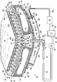
도 1은 예시적인 감압 복부 치료 시스템의 블럭도의 부분의 개략적인 단면;
도 2는 캡슐화된 레그 부재(encapsulated leg member)의 부분을 도시한 도 1의 예시적인 감압 복부 치료 시스템의 부분의 개략적인 단면도;
도 3은 캡슐화된 레그 부재의 부분을 도시한 도 1의 예시적인 감압 복부 치료 시스템의 부분의 개략적인 단면도;
도 4는 중심 연결 부재를 도시한 도 1의 예시적인 감압 복부 치료 시스템의 부분의 개략적인 단면도;
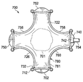
도 5는 도 1의 개방 공동 감압 치료 장치의 개략적인 사시도;
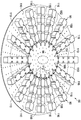
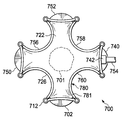
도 6은 또 다른 예시적인 실시예에 따른 개방 공동 감압 치료 장치의 개략적인 평면도;
도 7은 도 6의 상세한 치료 장치의 개략적인 평면도;
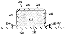
도 8은 도 7의 라인 8-8을 절개한 치료 장치의 부분의 개략적인 단면도;
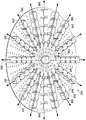
도 9는 개방 공동 감압 치료 장치의 또 다른 예시적인 실시예의 개략적인 사시도;
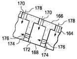
도 10은 도 1의 예시적인 상세한 깊은-조직 폐쇄 서브시스템의 개략적인 단면도;
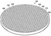
도 11은 일 예시적인 실시예에 따라서, 수축성 매트릭스(contractible matrix)의 제 1 측(상부)을 도시하는 개략적인 사시도;
도 12는 도 11의 수축성 매트릭스의 제 2 (내부-방향(inward-facing))측을 도시한 개략적인 사시도;
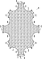
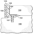
도 13은 수축성 매트릭스의 또 다른 예시적인 실시예의 개략적인 상부도;
도 14는 도 13의 수축성 매트릭스의 상세한 부분을 나타낸 도면;
도 15는 수축성 매트릭스의 예시적인 실시예의 부분의 개략적인 사시도;
도 16은 도 1의 예시적인 표면-상처 폐쇄 서브시스템의 부분의 개략적인 단면도;
도 17a는 감압 표면-상처 폐쇄 서브시스템의 예시적인 실시예의 개략적인 사시도;
도 17b 및 17c는, 비-수축 위치(도 17b) 및 수축 위치(도 17c)를 도시한 도 17a의 감압 표면-상처 폐쇄 시스템의 개략적인 평면도;
도 18은 표면-상처 폐쇄 서브시스템의 예시적인 실시예의 부분으로서 사용되는 부착-베이스 부재(attachment-base member)의 예시적인 실시예의 개략적인 사시도;
도 19는 표면-상처 폐쇄 서브시스템의 예시적인 실시예의 부분으로서 사용되는 연결 부재의 예시적인 실시예의 개략적인 사시도;
도 20은 표면-상처 폐쇄 서브시스템의 예시적인 실시예의 부분으로서 사용되는 감압 계면 부재의 예시적인 실시예의 개략적인 사시도;
도 21a 및 21b는 비-수축 위치(도 21a) 및 수축 위치(도 21b)에 도시된 감압 표면-상처 폐쇄 서브시스템의 예시적인 실시예의 개략적인 평면도;
도 22는 모듈 감압 표면-상처 폐쇄 서브시스템(modular, reduced-pressure, surface-wound closure subsystem)의 예시적인 실시예의 개략적인 사시도;
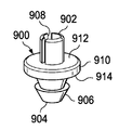
도 23a는 예시적인 감압 커넥터의 개략적인 사시도;
도 23b는 도 23a의 감압 커넥터의 정면도;
도 24a는 감압 상처-폐쇄 및 치료 시스템의 또 다른 예시적인 실시예의 부분의 개략적인 단면도;
도 24b는 감압 상처-폐쇄 및 치료 시스템의 또 다른 예시적인 실시예의 부분의 개략적인 단면도;
도 25는 다른 것들 중에서, 복수의 모듈 폐쇄 부재들의 예시적인 실시예를 제시한 감압 표면-상처 폐쇄 서브시스템의 부분의 예시적인 실시예의 개략적인 사시도;
도 26은 도 25의 모듈 폐쇄 부재의 부분의 개략적인 단면도;
도 27은 환자의 표면 상처에 걸쳐 가해진 도 25-26의 예시적인 상처-폐쇄 서브시스템의 개략적인 사시도;
도 28은 밀봉 수축 부재의 예시적인 실시예의 부분의 예시적인 실시예의 개략적인 단면도; 및
도 29는 부착 부재의 예시적인 실시예의 개략적인 단면도이다.1 is a schematic cross-sectional view of a portion of a block diagram of an exemplary decompression abdominal treatment system;
FIG. 2 is a schematic cross-sectional view of a portion of the exemplary decompression abdominal treatment system of FIG. 1 showing a portion of an encapsulated leg member. FIG.
3 is a schematic cross-sectional view of a portion of the exemplary reduced pressure abdominal treatment system of FIG. 1 showing a portion of an encapsulated leg member;
4 is a schematic cross-sectional view of a portion of the exemplary decompression abdominal treatment system of FIG. 1 showing a central connecting member;
5 is a schematic perspective view of the open cavity decompression treatment apparatus of FIG. 1;
6 is a schematic plan view of an open cavity decompression treatment device according to another exemplary embodiment;
7 is a schematic plan view of the detailed treatment device of FIG. 6;
FIG. 8 is a schematic cross-sectional view of a portion of the treatment device cut in line 8-8 of FIG. 7; FIG.
9 is a schematic perspective view of another exemplary embodiment of an open cavity decompression treatment device;
10 is a schematic cross-sectional view of the exemplary detailed deep-tissue closure subsystem of FIG. 1;
FIG. 11 is a schematic perspective view showing a first side (top) of a contractible matrix, in accordance with an exemplary embodiment; FIG.
FIG. 12 is a schematic perspective view showing a second (inward-facing) side of the shrinking matrix of FIG. 11;
13 is a schematic top view of another exemplary embodiment of a shrinking matrix;
FIG. 14 shows a detailed portion of the shrinking matrix of FIG. 13; FIG.
15 is a schematic perspective view of a portion of an exemplary embodiment of a shrinking matrix;
FIG. 16 is a schematic cross-sectional view of a portion of the exemplary surface-wound closure subsystem of FIG. 1;
17A is a schematic perspective view of an exemplary embodiment of a pressure reducing surface-wound closure subsystem;
17B and 17C are schematic plan views of the reduced pressure surface-wound closure system of FIG. 17A showing the non-retracted position (FIG. 17B) and the retracted position (FIG. 17C).
18 is a schematic perspective view of an exemplary embodiment of an attachment-base member used as part of an exemplary embodiment of a surface-wound closure subsystem.
19 is a schematic perspective view of an exemplary embodiment of a connecting member used as part of an exemplary embodiment of a surface-wound closure subsystem.
20 is a schematic perspective view of an exemplary embodiment of a pressure sensitive interface member used as part of an exemplary embodiment of a surface-wound closure subsystem.
21A and 21B are schematic plan views of an exemplary embodiment of the reduced pressure surface-wound closure subsystem shown in the non-retracted position (FIG. 21A) and the retracted position (FIG. 21B).
FIG. 22 is a schematic perspective view of an exemplary embodiment of a modular, reduced-pressure, surface-wound closure subsystem; FIG.
23A is a schematic perspective view of an exemplary pressure reducing connector;
FIG. 23B is a front view of the pressure reducing connector of FIG. 23A; FIG.
24A is a schematic cross-sectional view of a portion of another exemplary embodiment of a decompression wound-closure and treatment system;
24B is a schematic cross-sectional view of a portion of another exemplary embodiment of a decompression wound-closure and treatment system;
FIG. 25 is a schematic perspective view of an exemplary embodiment of a portion of a pressure sensitive surface-wound closure subsystem showing, among other things, an exemplary embodiment of a plurality of module closure members; FIG.
FIG. 26 is a schematic cross sectional view of a portion of the module closure member of FIG. 25; FIG.
27 is a schematic perspective view of the example wound-closure subsystem of FIGS. 25-26 applied across a surface wound of a patient.
28 is a schematic cross sectional view of an exemplary embodiment of a portion of an exemplary embodiment of a sealing shrink member; And
29 is a schematic cross-sectional view of an exemplary embodiment of the attachment member.
예시적인 실시예들의 다음의 상세한 설명에 있어서, 참조 부호는 그 부분을 형성하는 첨부된 도면에 따라 만들어진다. 이러한 실시예들은 기술 분야의 당업자가 본 발명을 실시할 수 있도록 충분히 상세하게 설명되고, 다른 실시예들은 이용될 수 있고, 논리상 구조적인, 기계적인, 전기적인, 및 화학적인 변화들은 본 발명의 사상 또는 권리 범위로부터 벗어남 없이 만들어질 수 있다. 기술 분야의 당업자가 본 발명을 실시하도록 하는데 필요하지 않은 상세한 설명을 피하기 위하여, 상기 상세한 설명은 기술 분야의 당업자에게 공지된 특정 정보를 생략할 수 있다. 그러므로, 이하의 설명된 상세한 설명은 한정된 의미로 나타나지 않고, 예시적인 실시예들의 권리 범위는 단지 부가된 청구항에 의해서만 규정된다.
In the following detailed description of exemplary embodiments, reference numerals are made in accordance with the accompanying drawings that form a part thereof. These embodiments are described in sufficient detail to enable those skilled in the art to practice the invention, and other embodiments may be utilized, and logical structural, mechanical, electrical, and chemical changes of the invention It can be made without departing from the spirit or scope of rights. In order to avoid detail that is not necessary for a person skilled in the art to practice the present invention, the above description may omit specific information known to those skilled in the art. The following detailed description, therefore, is not to be taken in a limiting sense, and the scope of the exemplary embodiments is defined only by the appended claims.
시스템 소개System introduction
도 1을 주로 참조하면, 감압 복부 치료 시스템(30)의 예시적인 실시예가 제시된다. 감압 복부 치료 시스템(30)은 환자의 복강(32) 및 개방된 복부에 연관된 조직 또는 상처를 치료, 또는 관리하기 위해 사용된다. 본원에서 사용되는 바와 같이, "상처"는 조직의 손상된 영역을 의미한다. 감압 복부 치료 시스템(30)은 일반적인 조직 부위(34); 깊은 조직, 예를 들면 근막(36), 근육(40), 지방 층(42)의 깊은-조직 상처; 및 표피(44)의 표면 상처(180)를 치료하기 위해 사용될 수 있다. 근막(36)의 상처는 근막 에지들(38)을 가진다. 표피(44)의 표면 상처(180)는 표면-상처 에지들(182)을 가진다. 조직 부위(34)는 복부 내용물(46) 상에 또는 복부 내용물(46)에 근접하여 도시된다. 조직 부위(34)는 인간, 동물, 또는 다른 기관의 몸체 조직일 수 있다. 이 실시예에서, 조직 부위(34)는 일반적으로 복강(32)의 조직 및 복부 내용물(46)에 근접한 보통의 조직을 포함한다.Referring primarily to FIG. 1, an exemplary embodiment of a decompression
감압 복부 치료 시스템(30)은, 개방 공동 치료 서브시스템(52)의 부분인 개방 공동 치료 장치(50)를 포함한다. 개방 공동 치료 서브시스템(52)은 환자의 복강(32)에 감압치료를 제공하는데 도움을 주고,복부 내용물(46)을 위한 비-접착성 커버를 구비한다. 감압 복부 치료 시스템(30)은 또한, 깊은-조직 폐쇄 서브시스템(56)의 부분인 깊은-조직 폐쇄 장치(54)를 포함한다. 깊은-조직 폐쇄 서브시스템(56)은 조직 상에 폐쇄력을 가하고, 특히 깊은 조직, 예를 들면, 근막(36) 상에 폐쇄력을 제공하기에 매우 적합하다. 깊은-조직 폐쇄 서브시스템(56)은 근막 에지들(38)에 인접하여 도움을 줄 수 있다. 감압 복부 치료 시스템(30)은 또한, 감압 치료 서브시스템(58)과 함께 일반적인 감압 치료를 제공한다. 표피(44) 상의 표면 상처(180), 특히, 표면-상처 에지들(182)은 중심 부분을 향하여, 또는 서로를 향해, 표면-상처 폐쇄 서브시스템(60)에서 일어난 폐쇄력에 의해, 자극을 받을 수 있다(urged). 최종적으로, 감압 복부 치료 시스템(30)은 감압 공급 서브시스템(62)을 포함할 수 있고, 상기 감압 공급 서브시스템(62)은 감압 복부 치료 시스템(30) 내의 다양한 장치들 및 서브시스템들에 감압을 제공한다. 각각의 장치들 및 서브시스템들은 이하에서 더 상세하게 기술된다.The decompression
감압 복부 치료 시스템(30)에 의해 전달된 감압은, 삼출물, 복수(ascites), 또는 다른 액체, 박테리아, 피부린(fibrin), 죽은 조직, 독소, 잔류 혈액 등의 제거를 촉진시키는데 도움을 주기 위해 복강(32) 및 조직 부위(34)에 가해질 수 있다. 일부 예들에서, 감압은 추가적인 조직의 성장을 자극시키기 위해 가해질 수 있고, 일부 예들에서, 단지 유체 제거만이 필요할 수 있다. 조직 부위(104)의 상처의 경우에서, 육아 조직(granulation tissue)의 성장, 및 삼출물 및 박테리아의 제거는 상처의 치료를 촉진시키는데 도움을 줄 수 있다. 본원에서 사용되는 바와 같이, "감압"은 일반적으로, 치료받는 조직 부위(34)의 대기압보다 낮은 압력을 일컫는다. 대부분 경우, 이러한 감압은 환자가 위치하는 곳의 대기압보다 낮을 것이다. 대안적으로, 감압은 조직 부위(34)에서 조직의 정수압(hydrostatic pressure)보다 낮을 수 있다. 별다른 지시가 없는 한, 본원에서 제시된 압력 값은 게이지 압력(gauge pressures)이다.
Decompression delivered by the abdominal
감압 치료 서브시스템Decompression Therapy Subsystem
감압 서브시스템, 예를 들면, 감압 서브시스템(58)의 예시적인 실시예가 이제 제시된다. 감압 치료 서브시스템(58)은 매니폴드(64), 밀봉 부재(66)(또는 오버-드레이프(over-drape)), 및 감압 계면(72)을 포함한다. 매니폴드(64)는 복강(32) 내에서 배치되는 것으로 도시된다. 밀봉 부재(66)는 복강(32) 상에 공기압 밀봉을 형성하기 위해 표피(44) 상의 표면 상처(180) 상에 위치된다.An exemplary embodiment of a decompression subsystem, eg,
매니폴드(64)는 많은 형태를 취할 수 있다. 본원에서 사용되는 바와 같이, 용어 "매니폴드"는 일반적으로, 조직 부위, 예를 들면, 조직 부위(34)에 유체를 전달하기 위해, 또는 상기 조직 부위로부터 유체를 제거하기 위해 감압을 가하는데 도움을 주도록 구비된 재질 또는 구조물을 일컫는다. 매니폴드(64)는 통상적으로 복수의 유동 채널들 또는 경로들을 포함하고, 상기 복수의 유동 채널들 또는 경로들은 매니폴드(64) 주위의 조직의 영역에 제공되는 유체 및 상기 조직의 영역으로부터 제거된 유체를 배분한다. 매니폴드(64)는 복수의 유동 채널들 또는 경로들을 포함할 수 있고, 상기 복수의 유동 채널들 또는 경로들은 유체의 분배를 향상시키기 위해 상호 연결된다. 매니폴드(64)는 생체적합성 물질일 수 있고, 상기 생체적합성 물질은 조직에 접착되어 위치될 수 있고, 감압을 분배시킬 수 있다. 매니폴드(64)의 예들은, 유동 채널들, 상기 유동 채널을 포함하거나 상기 유동 채널을 포함하여 치료할 수 있는 셀룰라 폼(cellular foam), 예를 들면 개방형 셀 폼(open-cell foam), 다공성 조직 집진부(porous tissue collections), 액체, 겔 및 폼을 형성하기 위해 배치된 구조적인 소자를 가지는 장치들을 포함할 수 있지만, 이에 한정되지 않는다. 매니폴드(64)는 다공성일 수 있고, 폼, 거즈, 펠트형 매트(felted mat) 또는 특히 생체 적용에 적합한 다른 물질로 구성될 수 있다. 일 실시예에서, 매니폴드(64)는 다공성 폼이고, 유동 채널들로 작용하는 복수의 상호연결된 셀들 또는 기공들을 포함한다. 다공성 폼은 폴리우레탄, 개방-셀, 망형 폼, 예를 들면 텍사스, 산 안토니오의 Kinetic Concepts, Incorporated에 의해 제조되는 Granufoam® 물질일 수 있다. 다른 실시예들은 유체가 매니폴드(64)로 흐르도록 하는 "폐쇄형 셀들"을 포함한다. 일부 상황들에서, 매니폴드(64)는 또한, 유체, 예를 들면, 약제, 항균성 치료제(antibacterials), 성장 인자 및 다양한 용액을 복강(32) 또는 조직 부위(34)로 분배하기 위해 사용될 수 있다. 다른 층들은 매니폴드(64), 예를 들면, 흡수성 물질, 위킹 물질(wicking material), 소수성 물질 및 친수성 물질에 포함될 수 있다.
밀봉 부재(66)는 밀봉 부재(66)와 환자의 표피(44) 사이에서 공기압 밀봉을 제공하기 위해 복강(32) 및 표면 상처(180) 상에 위치된다. 공기압 밀봉은 조직 부위(34)에서 감압을 유지시키기 위해 감압 복부 치료 시스템(30)에 적합하다. 밀봉 부재(66)는 도 1에 도시된 바와 같이, 중심 연결 부재(96) 상에 또는 깊은-조직 폐쇄 서브시스템(56)의 부분 상에 매니폴드(64)를 고정하기 위해 사용될 수 있다. 밀봉 부재(66)가 불투과성 또는 반투과성을 가질 수 있는 한편, 밀봉 부재(66)는, 밀봉 부재(66) 및 다른 시스템 구성요소들을 설치한 후에, 조직 부위(34)에서 감압을 유지시킬 수 있다. 밀봉 부재(66)는 실리콘계 합성물, 아크릴, 히드로겔(hydrogel) 또는 히드로겔-포밍 물질(hydrogel-forming material), 또는 다른 생체적합성 물질(조직 부위에 필요한 불투과성 또는 투과성 특성을 포함)로 형성된 가요성 오버-드레이프, 커버 또는 막일 수 있다.The sealing
밀봉 부재(66)는, 환자의 표피(44)에, 또는 표면-상처 에지들(182) 주위의 가스켓 부재(gasket member)에 밀봉 부재(66)를 고정하는 부착 장치(68)를 더 포함할 수 있다. 부착 장치(68)는 많은 형태들을 취할 수 있다; 예를 들면, 접착제(70)는 공기압 밀봉을 환자의 표피(44)에 직접 또는 간접적으로 제공하기 위해, 밀봉 부재(66)의 주변 또는 밀봉 부재(66)의 부분을 따라 위치될 수 있다. 접착제(70)는 또한, 해제가능한 백킹(releasable backing) 또는 적용시에 제거되는 부재로 미리 적용될 수 있고 덮일 수 있다.The sealing
감압 계면(72)은 매니폴드(64)에서 제 1 감압 전달 도관(76)으로, 또는 그 역으로 유체의 통행을 가능케 한다. 감압 계면(72)은, 예로서, 포트 또는 커넥터(74)일 수 있다. 이로써, 매니폴드(64)를 사용하여 복강(32)으로부터 집진된 유체는 제 1 감압 전달 도관(76)으로 감압 계면(72)을 통해 들어갈 수 있다. 또 다른 실시예에서, 감압 복부 치료 시스템(30)은 감압 계면(72)을 배제시킬 수 있고, 제 1 감압 전달 도관(76)은 밀봉 부재(66)로, 그리고 매니폴드(64)로 직접 삽입될 수 있다. 제 1 감압 전달 도관(76)은 감압을 이동시키는 의료용 도관 또는 관 또는 다른 수단일 수 있다. 제 1 감압 전달 도관(76)은 감압 전달 및 유체 제거를 손쉽게 하기 위한 다수-루멘 부재(multi-lumen member)일 수 있다. 일 실시예에서, 제 1 감압 전달 도관(76)은 2 개의 루멘 도관이고, 이때, 하나의 루멘은 유체를 이동시키는 것이고, 다른 하나는 압력 센서와 연통하여 유체의 압력을 감지하는 것이다. 또 다른 실시예에서, 제 1 감압 도관(76)은 2 개의 개별적인 도관들 또는 2 개 이상의 루멘들을 가진 단일 도관일 수 있다.The reduced
감압은, 감압원(77)을 포함하는 감압 공급 서브시스템(62)에 의해 제 1 감압 전달 도관(76)으로 공급될 수 있다. 넓은 범위의 감압은 -50 mm Hg 내지 -500 mm Hg, 더 바람직하게는 -100 mm Hg 내지 -300 mm Hg의 범위에서 발생될 수 있다. 발생된 감압은 시간에 대해 일정하거나 변화될 수 있다. 일 예시적인 실시예에서, 감압원(77)은 -100 mm Hg, -125 mm Hg 및 -150 mm Hg용 프리셋 선택기들(preset selectors)을 포함한다. 감압원(77)은 또한, 많은 알람들, 예를 들면 막혔다는 알람, 누출용 알람, 또는 캐니스터가 가득 찼다는 알람(canister full alarm) 또는 배터리가 적다는 알람도 포함할 수 있다. 감압원(77)은 휴대용 소스(portable source), 월 소스(wall source), 진공 펌프 또는 다른 유닛일 수 있다. 감압 공급 서브시스템(62)은 하루 당 5 리터 또는 그 이상만큼이나 제거된 유체를 수용하기 위해 필요할 수 있다.Decompression may be supplied to the first
서로 다른 많은 장치들, 예를 들면, 대표적인 장치(78)는 제 1 감압-전달 도관(76)의 중간 부분(80)에 추가될 수 있다. 예를 들면, 대표적인 장치(78)는 유체 저장부, 또는 캐니스터 집진 부재(canister collection member), 압력-피드백 장치, 부피 검출 시스템, 혈액 검출 시스템, 감염 검출 시스템, 필터, 필터를 가진 포트, 유동 모니터링 시스템, 온도 모니터링 시스템 등일 수 있다. 다수의 장치들, 예를 들면, 대표적인 장치(78)는 포함될 수 있다. 이러한 장치들 중 일부, 예를 들면, 유체 집진 부재는 감압원(77)에 일체형으로 형성될 수 있다. 예를 들면, 감압원(77) 상의 감압 포트(82)는 필터 부재(미도시)를 포함할 수 있고, 상기 필터 부재는 하나 이상의 필터들을 포함하고, 액체가 내부 공간으로 들어가지 못하도록 하는 소수성 필터를 포함할 수 있다.
Many different devices, for example
개방 공동 치료 서브시스템 및 치료 장치들Open Joint Therapy Subsystem and Treatment Devices
개방 공동 치료 서브시스템(52)은 복강(32) 또는 조직 부위(34)를 치료하기 위한 것이다. 개방 공동 치료 서브시스템(52)은 이제 더 상세하게 제시된다.The open
도 1-5를 참조하면, 개방 공동 치료 서브시스템(52)은, 복강(32) 내에 배치된 개방-공동 치료 장치(50)를 포함할 수 있다. 개방 공동 치료 장치(50)는, 비-접착성 드레이프(108)에 연결될 수 있는 복수의 캡슐화된 레그 부재들(90)을 포함한다. 비-접착성 드레이프 및 복수의 캡슐화된 레그 부재들(90)은 복부 내용물(46)에 의해 지지된다. 하나 이상의 복수의 캡슐화된 레그 부재들(90)은 제 1 대장측 홈(paracolic gutter)(92)에 또는 상기 제 1 대장측 홈에 근접하여 위치될 수 있고, 하나 이상의 복수의 캡슐화된 레그 부재들(90)은 제 2 대장측 홈(94)에 또는 상기 제 2 대장측 홈에 근접하여 위치될 수 있다. 대안적으로 또는 추가로, 복수의 캡슐화된 레그 부재들(90)은 원하는 다른 위치, 예를 들면, 간 뒤에 있는 골반 안(pelvic cavity) 등에 위치될 수 있다. 각각의 복수의 캡슐화된 레그 부재들(90)은 중심 연결 부재(96)에 연결된다. 복수의 캡슐화된 레그 부재들(90) 및 중심 연결 부재(96)는 유체를 전달한다. 복수의 캡슐화된 레그 부재들(90) 및 중심 연결 부재(96) 모두는, 복강(32)의 유체가 갈 수 있도록 하는 개창부들(fenestrations)(98, 100, 102, 104)로 형성된다. 개창부들(98, 100, 102, 104)은 임의의 형상, 예를 들면, 원형 개방부들, 직사각형 개방부들, 다각형 등을 취할 수 있지만, 그러나, 슬릿들(slits)(길게 형성된 개방부들)로서 이 예시적인 실시예에서 나타나게 된다.1-5, open
개방 공동 치료 장치(50)는 비-접착성 드레이프(108)를 포함하고, 상기 비-접착성 드레이프(108)는 비접착성 드레이프(108)에 조직이 접착되지 않도록 도움을 주는 비-접착성 막 물질로 형성될 수 있다. 일 실시예에서, 비-접착성 드레이프(108)는 통기성 폴리우레탄 막으로 형성된다. 비-접착성 드레이프(108)는 임의의 형상을 취할 수 있는 복수의 개창부들(110)로 형성된다. 개방 공동 치료 장치(50)는 중심 연결 부재(96)를 포함하고, 상기 중심 연결 부재(96)에는 복수의 캡슐화된 레그 부재들(90)이 연결된다. 중심 연결 부재(96)는, 유체가 캡슐화된 레그 부재들(90)에 전달되도록 하는 레그 연결 영역들(112)을 제외하고, 중심 연결 부재(96)의 에지들을 포함하여 캡슐화될 수 있다. 중심 연결 부재(96)는 개구부들 또는 개창부들, 예를 들면, 개구부들(104)을 가지고, 상기 개구부들(104)은 유체가 연결 매니폴드 부재(114)와 매니폴드(64) 사이에서 전달되도록 한다. 연결 매니폴드 부재(114)와 매니폴드(64) 사이의 유체 전달은 깊은-조직 폐쇄 장치(54)를 통해 이루어질 수 있다.The open
각각의 캡슐화된 레그 부재들(90)은 복수의 정의된 레그 모듈들, 예를 들면, 레그 모듈들(116)로 형성될 수 있다. 조작 영역(manipulation zone)(118)은 인접한 레그 모듈들(116) 사이에서 위치될 수 있다. 조작 영역들(118)은 개방-공동 치료 장치(50)의 이동을 용이하게 하고, 개방-공동 치료 장치(50)를 치수화시키기 위해 개방 공동 치료 장치(50)의 절단을 용이하게 한다.Each encapsulated
각각의 캡슐화된 레그 부재(90)는 레그 매니폴드 부재(120)를 가지고, 상기 레그 매니폴드 부재(120)는 레그 모듈들(116) 사이에서 진행되는 단일 매니폴드 부재일 수 있거나, 레그 매니폴드 부재(120)를 구성하는 개별적인 매니폴드 물질의 구성요소들로 형성될 수 있다. 레그 매니폴드 부재(120)는 캡슐화된 레그 부재(90)의 내부 부분(122) 내에 배치된다. 레그 매니폴드 부재(120)는 제 1 측(124) 및 제 2 내부-방향(환자-방향) 측(126)을 가진다. 개창부들(98)로 형성된 제 1 레그 캡슐형 부재(leg encapsulating member)(128)는 레그 매니폴드 부재(120)의 제 1 측(124) 상에 배치된다. 이와 유사하게, 개창부들(100)을 가진 제 2 레그 캡슐형 부재(130)는 레그 매니폴드 부재(120)의 제 2 내부-방향 측(126) 상에 배치된다. 제 2 레그 캡슐형 부재(130)는 비-접착성 드레이프(108)의 부분일 수 있다. 도 2의 길이방향 단면에서 도시된 바와 같이, 화살표들(132)에 의해, 유체는 인접한 레그 모듈들(116) 사이를 흐를 수 있다. 화살표들(134)에 의해, 유체는 개창부들(98 및 100)에 들어갈 수 있고, 레그 매니폴드 부재(120)로 흐를 수 있고, 그 후에, 유동 화살표들(132)로 나타난 바와 같이, 중심 연결 부재(96)를 향하여 흐를 수 있다.Each encapsulated
이제, 도 3을 주로 참조하면, 캡슐화된 레그 부재(90)의 측면 단면도가 도시된다. 이전과 같이 볼 수 있는 바와 같이, 레그 매니폴드 부재(120)의 제 1 측(124)은 제 1 레그 캡슐형 부재(128)로 덮이고, 레그 매니폴드 부재(120)의 제 2 내부-방향 측(126)은 제 2 레그 캡슐형 부재(130)로 덮인다. 주목되어야 하는 바와 같이, 제 1 레그 캡슐형 부재(128) 및 제 2 레그 캡슐형 부재(130)는 레그 매니폴드 부재(120) 상에 접혀진 그리고 밀봉된 단일 시트(sheet)일 수 있다. 예시적인 실시예에서, 제 2 레그 캡슐형 부재(130)는 비-접착성 드레이프(108)의 부분이다. 레그 매니폴드 부재(120)는 주변 에지들(136)을 가지고, 상기 주변 에지들(136)은 또한, 제 1 레그 캡슐형 부재(128)의 부분으로 덮이게 된다. 주변 에지들(136)은 제 1 측면 에지(137) 및 제 2 측면 에지(139)를 포함한다. 제 1 레그 캡슐형 부재(128)는 제 1 측(124) 및 주변 에지들(136)을 덮고, 비-접착성 드레이프(108)의 제 1 표면(138) 상에서 연장되어 연장부들(140)을 형성할 수 있다. 연장부들(140)은 부착 장치, 예를 들면, 용접(예를 들면, 초음파 또는 RF 용접), 결합제, 접착제, 시멘트 등에 의해, 이 예에서는 용접(142)에 의해 제 2 레그 캡슐형 부재(130)에 연결된다.Referring now primarily to FIG. 3, a side cross-sectional view of an encapsulated
이제, 도 4를 주로 참조하면, 중심 연결 부재(96)의 부분의 개략적인 단면도가 도시된다. 중심 연결 부재(96)는 연결 매니폴드 부재(114)로 형성되고, 상기 연결 매니폴드 부재(114)는, 개창부들(102)을 가진 제 1 연결 캡슐형 부재(146) 및 개창부들(104)을 가진 제 2 연결 캡슐형 부재(152)로 캡슐화가 된다. 제 1 연결 캡슐형 부재(146)는 연결 매니폴드 부재(114)의 제 1 측(148) 상에 배치된다. 연결 매니폴드 부재(114)의 제 2 내부-방향 측(150)은, 제 2 내부-방향 측(150)에 근접하게 배치된 제 2 연결 캡슐형 부재(152)를 가진다. 도 4 및 5를 주로 참조하면, 제 1 연결 캡슐형 부재(146)는 주변 에지(154)를 가진다. 이와 유사한 방식으로, 제 2 연결 캡슐형 부재(152)는 제 1 연결 캡슐형 부재(146)의 주변 에지(154)에 대응되는 주변 에지를 가진다. 제 1 연결 캡슐형 부재(146)의 주변 에지(154)는 레그 연결 영역들(112)을 제외하고, 제 2 연결 캡슐형 부재(152)의 주변 에지에 연결됨으로써, 캡슐화된 레그 부재들(90) 내의 유체가 참조 화살표들(156)로 제시된 바와 같이, 연결 매니폴드 부재(114)로 흐르는 유동 채널들을 구비할 수 있다. 유체는 또한, 화살표들(158)로 제시된 바와 같이, 개창부들(104)을 통하여 흐름으로써, 연결 매니폴드 부재(114)로 직접 들어갈 수 있다.Referring now primarily to FIG. 4, a schematic cross-sectional view of a portion of the
깊은-조직 폐쇄 장치(54)는 제 1 연결 캡슐형 부재(146)에 근접하여 배치된다. 감압이 매니폴드(64)에 가해지면, 감압은 깊은-조직 폐쇄 장치(54)를 통하여 전달되고, 유체가 연결 매니폴드 부재(114)로부터 개창부들(102) 및 깊은-조직 폐쇄 장치(54)를 통하여, 화살표들(160)로 제시된 바와 같이, 매니폴드(64)로 흐르도록 한다. 유체는 감압 계면(72)의 방향으로 연속적으로 흐를 수 있고, 상기 감압 계면으로부터 제 1 감압 전달 도관(76)으로 흐르게 된다.Deep-
이제, 주로 도 6-8을 참조하면, 도 1의 감압 복부 치료 시스템(30)으로 사용될 수 있는 개방-공동 치료 장치(202)의 또 다른 예시적인 실시예가 제시된다. 개방 공동 치료 장치(202)는 도 1-5의 개방 공동 치료 장치(50)와 가장 유사하다. 개방 공동 치료 장치(202)는 비-접착성 드레이프(204), 복수의 캡슐화된 레그 부재들(206) 및 중심 연결 부재(208)를 가진다. 이 예시적인 실시예에서, 비접착성 드레이프(204)는 타원형 또는 아치형 형상으로 형성되지만, 다양한 형상들도 가능하다. 비-접착성 드레이프(204)는 이를 통한 복수의 개창부들(205)로 형성된다. 비-접착성 드레이프(204)는 또한, 제 2 레그 캡슐형 부재(228) 및 제 2 연결 캡슐형 부재(미도시이지만, 도 4의 152와 유사함)을 형성하고, 비-접착성 드레이프(204)의 개창부들(205)은 제 2 내부-방향 측 상의 중심 연결 부재(208) 및 캡슐화된 레그 부재들(206)을 위한 유동 채널들을 역할한다.Referring now primarily to FIGS. 6-8, another exemplary embodiment of an open-
각각의 복수의 캡슐화된 레그 부재들(206)은 인접한 레그 모듈들(210) 사이에서 조작 영역들(212)을 구비한 복수의 레그 모듈들(210)로 형성될 수 있다. 조작 영역들(212)은 복강 내에서 복수의 캡슐화된 레그 부재들(206)의 조작을 용이하게 하고, 개방 공동 치료 장치(202)가 치수화될 시에 캡슐화된 레그 부재들(206)이 절단될 수 있는 보다 쉬운 위치를 제공한다. 이에 대해, 시각적 표시부(visual indicia)(214)는 비-접착성 드레이프(204)에 추가될 수 있어, 의료 제공자가 복강 내에 적용되는, 서로 다른 크기를 가진 비-접착성 드레이프(204)를 어디에서 절단할 지에 대한 도움을 준다. 시각적 표시부(214)는 생체적합성 잉크 또는 용접 또는 개창부 또는 다른 마킹(적어도 부분적으로 조작 영역들(212)을 통하여 진행됨)으로 형성된 절단 라인들을 포함할 수 있다. 시각적 표시부(214)는 또한 크기 눈금(size graduations)을 보여줄 수 있다.Each of the plurality of encapsulated
이제, 주로 도 8을 참조하면, 캡슐화된 레그 부재(206)의 측면 단면도가 제시된다. 캡슐화된 레그 부재들(206)은 제 1 측(220) 및 제 2 내부-방향 측(222)을 가진 레그 매니폴드 부재(218)로 형성된다. 제 1 레그 캡슐형 부재(224)는 레그 매니폴드 부재(218)의 제 1 측(220)을 덮고, 레그 매니폴드 부재(218)의 측면 에지들(226)을 덮는다. 레그 매니폴드 부재(218)의 제 2 내부-방향 측(222)은 제 2 레그 캡슐형 부재(228)로 덮이고, 상기 제 2 레그 캡슐형 부재(228)는 이 실시예에서 비-접착성 드레이프(204)의 부분이다. 제 1 레그 캡슐형 부재(224)는 기술 분야에서 공지된 수단, 예를 들면, 용접(예를 들면, 초음파 또는 RF 용접), 결합제, 접착제, 시멘트 등에 의해 제 2 레그 캡슐형 부재(228)에 연결된다. 이 예에서, 제 1 레그 캡슐형 부재(224)는 용접(230)에 의해 제 2 레그 캡슐형 부재(228)에 연결된다. 용접(230)은 각각의 레그 모듈(210)의 주변 부분 상에서 또는 다른 곳에서 형성될 수 있다.Referring now primarily to FIG. 8, a side cross-sectional view of an encapsulated
중심 연결 부재(208)는 도 4의 중심 연결 부재(96)와 유사하게 형성된다. 제 1 연결 캡슐형 부재(234) 및 제 2 연결 캡슐형 부재(미도시이지만, 도 4의 제 2 연결 캡슐형 부재(152)와 유사함)는 용접(233) 또는 다른 연결 수단, 예를 들면, 용접(예를 들면, 초음파 또는 RF 용접), 결합제, 접착제, 시멘트 등을 사용하여 주변 에지(232)를 따라 연결된다. 제 1 캡슐형 부재(234)의 주변 에지(232) 및 제 2 캡슐형 부재는 캡슐화된 레그 부재들(206)과 중심 연결 부재(208) 사이에서 유체 흐름을 막도록 연결될 수 없다; 즉, 캡슐화된 레그 부재들(206)에서 중심 연결 부재(208)로 유체가 흘러가는 유동 통로는 존재한다.The
개방 공동 치료 장치(202)를 구성하는 일 예시적인 접근법에 따라서, 개창부들(205)로 형성되고 시각적 표시부(214)를 가질 수 있는 비-접착성 드레이프(204)는 실질적으로 평평한 표면 상에 위치되고, 그렇지 않다면, 평면 상에서 나타나게 된다. 레그 매니폴드 부재들(218)은 비-접착성 드레이프(204) 상에 위치된다. 중심 연결 부재(208)는 비-접착성 드레이프(204) 상에 위치된다. 대안적으로, 중심 연결 부재(208)는 레그 매니폴드 부재들(218)를 구비한 일체형 부재로 형성될 수 있고, 이 경우에, 중심 연결 부재(208) 및 레그 매니폴드 부재들(218)은 동시에 위치될 수 있다. 제 1 연결 캡슐형 부재(234)는 중심 연결 부재(208) 상에 위치되고, 제 1 레그 캡슐형 부재(224)는 레그 매니폴드 부재들(218)의 제 1 측 또는 상부(도 6에서 나타난 배향) 상에서 위치된다. 그 후에, 용접(230 및 233)은 적용된다. 이로써, 개방 공동 치료 장치(202)는 형성된다.In accordance with one exemplary approach to configuring the open
대안적인 실시예에서, 개창부들(205)을 포함한 제 1 비-접착성 드레이프(204)는 제 1 비-접착성 드레이프(204) 상에 위치된 중심 연결 부재(208) 및 레그 매니폴드 부재들(218)을 가질 수 있다. 그 후에, 개창부들을 가진 제 2 비-접착성 드레이프는 제 1 비-접착성 드레이프(204), 레그 매니폴드 부재들(218) 및 중심 연결 부재(208) 상에서 위치된다. 그 후에, 복수의 용접들(예를 들면, 열 또는 RF)은 만들어지고, 2 개의 비-접착성 드레이프들의 주변을 용접될 수 있다. 추가로, 드레이프 상에 다른 지점들은 함께 용접될 수 있다. 또 다른 대안에 있어서, 2 개의 비-접착성 드레이프들은 초기에 개창부들을 가질 수 없고, 개창부들은, 개창부들이 한 줄로 되도록 조립된 후에, 비-접착성 드레이프들에 개별적으로 추가될 수 있다. 개창부들은 또한 전기 부재(electrical member)로 형성될 수 있고, 상기 전기 부재는, 레그 매니폴드 및 중심 연결 부재가 없는 위치에서 2 개의 비-접착성 드레이프들을 통하여 "버튼 홀(button hole)" 개창부들을 형성하기 위해 동시에 절단되고 밀봉된다.In an alternative embodiment, the first
이제, 도 9를 참조하면, 개방 공동 치료 장치(302)의 또 다른 예시적인 실시예가 제시된다. 개방 공동 치료 장치(302)는 도 6에도 도시된 개방 공동 치료 장치(202)와 가장 유사하다. 개방 공동 치료 장치(302)는 비-접착성 드레이프(348) 상에서 복수의 캡슐화된 레그 부재들(306) 및 중심 연결 부재(312)를 가진다. 개방 공동 치료 장치(302)는, 유체 전달 서브시스템(345)이 추가된다는 점에서 개방 공동 치료 장치(202)와는 크게 다르다. 유체 전달 서브시스템(345)은 다양한 유체, 예를 들면, 약제 또는 세척 유체(irrigation fluid)가 복강에 전달되도록 한다. 그 후에, 다양한 유체는 복수의 캡슐화된 레그 부재들(306) 및 개방 공동 치료 장치(302) 그 자체의 작용에 의해 제거될 수 있다. 유체 전달 서브시스템(345)은 중심 포트 부재(347)를 포함하고, 상기 중심 포트 부재(347)는 복강 외부의 부위에서 중심 포트 부재(347)로 유체를 전달하는 전달 도관(미도시)에 연결되는 중심 연결 부재(312) 상에서 또는 상기 중심 연결 부재(312)에서 위치될 수 있다. 중심 포트 부재(347)는 복수의 유체-전달 도관들(349)에 유체적으로 연결된다. 유체-전달 도관들(349)은 비접착성 드레이프(348)의 어느 곳에서든지 진행될 수 있다. 예를 들면, 유체-전달 도관들(349)은 캡슐화된 레그 부재들(306)의 측들을 따라, 또는 비-접착성 드레이프(348)의 반대 측을 따라 진행될 수 있다. 이 예시적인 실시예에서, 유체-전달 도관들(349)은 복수의 캡슐화된 레그 부재들(306)을 통하여 진행되는 것으로 도시된다. 유체-전달 도관들(349)은 이들의 원위단들(distal ends)(351) 상에서 개방됨으로써, 이를 통하여 유체가 전달되도록 한다. 그러나, 유체 전달 도관들(349)은 유체를 전달하는 다양한 위치에서 개구부들을 가질 수 있고, 원위단들(351)에서 닫힐 수 있거나, 원위단들(351)에서 개방될 수 있다. 유체-전달 도관들(349)의 원위단들(351)을 통한 유체의 유동은 화살표들(353)로 제시된다.Referring now to FIG. 9, another exemplary embodiment of an open
사용에 있어, 개방 공동 치료 장치(302)는 개방 공동 치료 장치들(50 및 202)과 유사한 방식으로 사용될 수 있지만, 그러나 여러 시간에 걸쳐, 유체 전달 서브시스템(345)을 통하여 유체를 전달하는 것이 바람직할 수 있다. 예를 들면, 세척 유체로 복강에 흐르게 하거나, 정기적인 약제 투약을 전달시키는 것이 바람직할 수 있다.
In use, the open
깊은-조직 폐쇄 서브시스템 및 장치들 Deep-Tissue Closure Subsystems and Devices
도 1을 참조하면, 감압 복부 치료 시스템(30)의 깊은-조직 폐쇄 서브시스템(56)은 깊은 조직들, 예를 들면, 특히, 근막 에지들(38)에 근접한 근막(36)을 폐쇄하기 위해 사용될 수 있다. 깊은-조직 폐쇄 장치(54)를 포함한 깊은-조직 폐쇄 서브시스템(56)은 도시된다. 깊은-조직 폐쇄 서브시스템(56)은 특히, 근막(36)에서와 같은 깊은 조직을 포함한 복강(32) 내에서 사용하기에 매우 적합하다. 근막(36)의 상처는 근막 에지들(38)로 도시되고, 상기 근막 에지들(38)은 통상적으로 깊은-조직 상처를 정의한다. 근막 에지들(38)을 근접시킴으로써, 깊은-조직 상처 상에 폐쇄력을 닫히게 하거나 가하는 것이 바람직할 수 있다. 더 상세하게 기술되는 바와 같이, 깊은-조직 폐쇄 장치(54)는 이 목적에 도움을 준다.Referring to FIG. 1, the deep-tissue closure subsystem 56 of the decompression
깊은-조직 폐쇄 장치(54)는 개방 공동 치료 장치(50)의 상부 상에, 그리고 근막(36)의 하부 상에 위치될 수 있다. 도 1 및 10을 주로 참조하면, 깊은-조직 폐쇄 장치(54)는 수축성 매트릭스(164)를 포함하고, 상기 수축성 매트릭스(164)는 제 1 측(166) 및 제 2 내부-방향 측(168)을 가진다. 수축성 매트릭스(164)는 수축성 매트릭스 물질 또는 구조물을 통해 제 1 복수의 개구부들(170)로 형성된다. 수축성 매트릭스(164)는 또한, 복수의 셀들, 예를 들면, 개방 셀들(172)이 제 2 내부-방향 측(168) 상에서 형성되도록 형성될 수 있다. 복수의 셀들(172)은, 제 2 복수의 개구부들(176)을 포함할 수 있는 셀 벽들(174)로 형성될 수 있다. 제 1 복수의 개구부들(170)은 셀들(172) 상에서 중심에 위치될 수 있다.Deep-
감압이 수축성 매트릭스(164)에 전달될 시에, 그립력(gripping force)은 발생되고, 내부로 힘이 가해지게 된다. 감압은 그립력을 근막(36) 상에 제공하기 위해 제 1 복수의 개구부들(170)을 통하여 작용된다. 그립력은 근막(36)을 유지시키거나, 움켜쥐게 된다. 감압은 개방 공동 치료 장치(50), 셀들(172) 및 제 1 복수의 개구부들(170)에 유체가 전달되는 것을 통하여 (도시된 배향의) 밑에서부터 근막(36)에 공급될 수 있다. 감압은 추가로 또는 대안적으로, 매니폴드(64) 및 제 2 복수의 개구부들(176)을 통해 공급될 수 있다. 근막(36) 상의 그립력은 화살표들(178)에 의해 나타나게 된다.When decompression is transmitted to the shrinking
개구부들(170)을 통하여 그립력 제공함과 더불어, 감압은 또한 수축성 매트릭스(164)를 내부 방향으로, 즉, 화살표들(29)로 도시된 방향으로 가하게 된다. 이 문맥 상의 "내부 방향(inward)"은 감압의 깊은-조직 폐쇄 장치(54)의 중심 부분을 향한다는 것을 의미한다. 대안적으로, "내부 방향"은 배치된 감압의 깊은-조직 폐쇄 장치(54)에 대한 조직 상처의 근막 에지들(38)을 향하여, 조직, 예를 들면, 근막(36)을 잡아당길 수 있는 방향으로 정의될 수 있다. 감압이 수축성 매트릭스(164) 상에서 작용됨에 따라서, 수축성 매트릭스(164)는 근막(36)을 움켜잡을 수 있고, 비-수축 위치에서 수축 위치로 가게 된다. 일 실시예에서, 수축성 매트릭스(164)는 셀들을 포함하고, 상기 셀들은 측면으로 무너져서 접촉하게 된다. 셀들의 가요성을 가진 측 벽들은 감압의 영향으로 서로 더 가깝게 이동된다. 제 1 복수의 개구부들(170) 상의 감압이 근막(36)을 움켜잡고, 감압으로 인해 수축성 매트릭스(164)가 접촉되기 때문에, 폐쇄력은 일어나게 되고 근막(36)에 가해지게 되고, 상기 근막(36)은 근막 에지들(38)이 보다 더 근접하도록 한다. 이로써, 근막(36)은 폐쇄력을 받고, 감압을 사용하여 폐쇄 위치로 가까이 가게 되거나 가해질 수 있다.In addition to providing a grip force through the
일 실시예에서, 수축성 매트릭스(164)은 복수의 셀들, 예를 들면, 셀들(172)을 포함하고, 상기 셀들(172)은, 감압이 적용되지 않을 시, 예를 들면, 대기압 시의 제 1 부피(V1)를 집합적으로 정의한다. 감압이 셀들에 가해질 시에, 셀들은 무너지게 되거나, 그렇지 않으면 이동하게 됨으로써, 제 2 부피(V2)가 정의된다. 제 2 부피는 제 1 부피(V1)보다 작고, 즉, V1>V2 이고, 부피의 이러한 변화는 수축에 연관된다.In one embodiment, the shrinking
깊은-조직 폐쇄 서브시스템(56)은 깊은 조직, 예를 들면, 근막(36) 상에 폐쇄력을 제공할 수 있고, 복강(32) 내에 감압 치료를 제공하는데 도움을 줄 수 있고, 특히, 조직 부위(34)에 근접한 감압 치료를 제공할 수 있다. 감압은 복수, 삼출물 또는 다른 액체의 제거를 촉진시키는데 도움을 주기 위해 조직 부위(34) 및 복강(32)에 가해질 수 있다. 감압은 또한 추가 조직의 성장을 자극시키기 위해 가해질 수 있다.Deep-tissue closure subsystem 56 may provide closing force on deep tissue, eg,
깊은-조직 폐쇄 서브시스템(56)을 사용하여, 깊은-조직 폐쇄 장치(54)의 수많은 서로 다른 실시예들은 사용될 수 있다. 기능적으로, 깊은-조직 폐쇄 장치(54)가 깊은 조직에 구멍을 뚫는 일 없이, 깊은 조직을 움켜쥐는 것, 그리고 중심을 향해, 예를 들면, 깊은-조직 상처(165)의 중심으로 향해 깊은 조직을 잡아당기는 것이 바람직할 수 있다. 근막(36)에 가해질 시에, 깊은-조직 폐쇄 장치(54)는 근막 에지들(38)에 근접하게 된다.Using the deep-tissue closure subsystem 56, numerous different embodiments of the deep-
이제, 주로 도 11 및 12를 참조하면, 감압의 깊은-조직 서브시스템의 부분으로서 사용되는 수축성 매트릭스(400)가 도시된다. 수축성 매트릭스(400)는 제 1 측(402) 및 제 2 내부-방향 측(404)을 가진다. 도 11은 제 1 측(402)을 도시하고, 도 12는 제 2 내부-방향 측(404)을 도시한다. 특히, 이 예시적인 실시예에서, 수축성 매트릭스(400)는 고체 원형 형상으로 형성되지만, 그러나 많은 다른 형상들, 예를 들면, 도 13에 도시된 타원형 형상, 아치형 형상, 직사각형 형상, 불규칙한 형상 등이 사용될 수 있다. 수축성 매트릭스(400)의 제 1 측(402)은 상기 제 1 측을 통해 형성되고, 제 2 내부-방향 측(404)으로 연장되는 제 1 복수의 개구부들(406)을 가진다. 도 12에 도시된 바와 같이, 복수의 셀들(408)은 제 2 내부-방향 측(404) 상에서 형성된다. 셀들(408) 각각은 개구부(406) 및 개방 셀 부분을 가진다. 각각의 개방 셀(408)은 셀 벽들(410)로 형성된다. 각각의 셀 벽(410)은 셀 벽(410)을 통하여 세포 사이의(intercellular) 개구부를 가질 수 있어서, 도 10의 제 2 복수의 개구부들(176)과 유사한 제 2 복수의 개구부들을 형성할 수 있게 된다. 이 특별한 예시적인 실시예에서, 복수의 셀들(408)은 각각의 제 1 복수의 개구부들(406) 주위에서 중심에 위치된 벌집 셀들(honeycomb cells)로서 형성될 수 있다. 셀들(408)에 대한 다른 형상들은 이하에서 더 언급될 수 있다.Referring now primarily to FIGS. 11 and 12, a shrinking
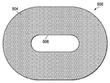
이제, 도 13-14를 참조하면, 수축성 매트릭스(500)의 또 다른 예시적인 실시예가 제시된다. 수축성 매트릭스(500)는 제 1 측 및 제 2 내부-방향 측(504)을 가진다. 이러한 특별한 예시적인 실시예의 수축성 매트릭스(500)는 중심 개방부(506)를 가진 타원형 형상으로 형성되지만, 도 11에서 도시된 바와 같이, 상기와 같은 개방부 없이도 형성될 수 있다. 도 14에 도시된 바와 같이, 수축성 매트릭스(500)의 제 2 내부-방향 측(504)은 제 1 복수의 개구부들(510) 상에 중심에 각각 위치된 복수의 셀들(508)로 형성될 수 있다. 복수의 셀들(508)은 복수의 상호 연결된 셀 벽들(512)로 형성될 수 있다. 셀 벽들은 도 10의 제 2 복수의 개구부들(176)과 유사한 셀 벽을 통하여 형성된 제 2 복수의 개구부들로 형성될 수 있다.Referring now to FIGS. 13-14, another exemplary embodiment of a shrinking
이제, 도 15를 참조하면, 수축성 매트릭스(520)의 또 다른 예시적인 실시예가 제시된다. 수축성 매트릭스(520)는 도 1의 감압의 깊은-조직 폐쇄 서브시스템(56)에서 사용될 수 있다. 이 예시적인 실시예에서, 수축성 매트릭스(520)는 직사각형 형상을 하고, 제 1 복수의 개구부들(522)을 가지고, 상기 제 1 복수의 개구부들(522)은 수축성 매트릭스(520)의 제 1 측(524)에서 제 2 내부-방향 측(526)으로 나아간다. 제 2 복수의 개구부들(528)은 제 1 복수의 개구부들(522) 또는 그의 일부 부분에 연결될 수 있다.Referring now to FIG. 15, another exemplary embodiment of a shrinking
대안적인 실시예에서, 수축성 매트릭스(520)는 제 1 측(524) 상에서 개구부들(522)을 가질 수 있지만, 그러나 제 2 내부-방향 측(526) 상에서 대응하는 개구부가 없을 수 있다. 이로써, 수축성 매트릭스(400)는 제 1 측(524)에만 개방된 셀들을 가지고, 감압을 셀들에 제공하는 개구부들(528)을 가질 수 있다. 감압이 개구부들(528)을 통하여 공급될 시에, 깊은 조직은 개구부들(522)에 의해 움켜 잡히게 되고, 셀들의 측 벽들은 수축성 매트릭스(520)가 접촉되도록 보다 근접하게 잡아 당겨진다.In an alternate embodiment, the
서로 다른 많은 재질들은 수축성 매트릭스들, 예를 들면, 도 1의 수축성 매트릭스(164), 도 11 및 12의 수축성 매트릭스(400), 도 13 및 14의 수축성 매트릭스(500) 및 도 15의 수축성 매트릭스(520)를 형성하기 위해 사용될 수 있다. 통상적으로, 가요성 수축성 물질은 매트릭스들에 사용된다. 예를 들면, 이러한 수축성 매트릭스들(164, 400, 500 및 520)은 가요성 TPE(thermal plastic elastomers); TPU(thermoplastic urethane); 실리콘 고무; 기타 그 외로 형성될 수 있다. 폼은 수축성 매트릭스들에 사용되지 않는다. 수축성 매트릭스들이 형성된 물질은 조직의 내성장(ingrowth)을 피하여 형성되는 것이 바람직하다. 게다가, 서로 다른 많은 셀의 기하학적인 형상들은 수축성 매트릭스들에서 이용될 수 있다. 예를 들면, 가능한 셀의 기하학적인 형상들은 벌집, 원형 형상, 다이아몬드 형상, 기어 형상(gear-shaped)을 가진 셀 등을 포함한다. 폼이 통상적으로 사용되지는 않지만, 일 실시예에서, 수축성 매트릭스는 조직을 움켜잡는 개구부들을 가진, 밀봉되거나 캡슐화된 폼 부재 및 감압 공급 계면으로 형성될 수 있다.Many different materials may be used for shrinking matrices such as the shrinking
일 예시적인 실시예에서, 수축성 매트릭스는 TPU 벌집 물질로 형성될 수 있고, 상기 TPU 벌집 물질은 통합 결합제(fusion bonding)로 형성된 벌집 셀들을 포함한다. 또 다른 예시적인 실시예에서, 수축성 매트릭스는 TPE(thermal plastic elastomer)로 형성될 수 있고, 상기 TPE는 xy 평면(도 13의 페이지 내의 평면)으로 팽창 및 수축을 가능케 하면서, z 방향(도 13의 페이지 외부를 향함(coming out of))으로는 상당히 일정한 크기를 유지시킬 수 있다. 이 실시예에서, 수축성 매트릭스는 xy 방향보다는 z 방향으로 집중된 보다 강한 물질(또는 그 이상의 물질)을 가질 수 있다. 대안적으로 또는 추가로, 보이드들(voids)은 무너짐(collapse)의 패턴을 규정하기 위해 추가될 수 있다. 대안적으로 또는 추가로, 강성 부재들, 예를 들면, 필라멘트들(filaments)은 z 방향으로 무너지는 것을 피하기 위해 상기 z 방향으로 추가될 수 있다. 또 다른 예시적인 실시예에서, 수축성 매트릭스는 TPU(thermoplastic urethane) 물질을 사용하여 형성될 수 있고, 상기 TPU 물질은 제 1 측 상의 수축성 매트릭스 상에서, 예를 들면, 도 11의 수축성 매트릭스(400)의 제 1 측(402) 상에서 추가적인 막을 가질 수 있다. 이러한 것들은 일부 예시적인 예들이다.
In one exemplary embodiment, the shrinkable matrix may be formed of a TPU honeycomb material, wherein the TPU honeycomb material comprises honeycomb cells formed of fusion bonding. In another exemplary embodiment, the shrinkable matrix may be formed of a thermal plastic elastomer (TPE), which allows the TPE to expand and contract in the xy plane (plane in the page of FIG. 13), while in the z direction (FIG. 13). Coming out of the page can maintain a fairly constant size. In this embodiment, the shrinkable matrix may have a stronger material (or more material) concentrated in the z direction rather than the xy direction. Alternatively or additionally, voids may be added to define the pattern of collapse. Alternatively or additionally, rigid members, for example filaments, may be added in the z direction to avoid collapsing in the z direction. In another exemplary embodiment, the shrinkable matrix may be formed using a thermoplastic urethane (TPU) material, the TPU material being formed on the shrinkable matrix on the first side, for example, of the
표면-상처 폐쇄 서브시스템Surface-Wound Closure Subsystem
도 1을 참조하면, 표면-상처 폐쇄 서브시스템(60)은 이제 제시된다. 표피(44) 상의 표면 상처(180)에, 특히 표면-상처 에지들(182) 사이에 폐쇄력을 제공하는데 도움을 주는 것이 바람직하다. 도 1 및 16에 도시된 바와 같이, 표면-상처 폐쇄 서브시스템(60)은 이 목적에 사용될 수 있다. 표면-상처 폐쇄 서브시스템(60)은 표피(44)에 전달되는, 화살표들(184)에 의해 나타난 폐쇄력을 일으키고, 표면-상처 에지들(182)을 서로 향해 가한다. 표면-상처 폐쇄 서브시스템(60)은 제 1 베이스 부재(177) 및 제 1 벽(188) 또는 벽 부재(도 16)를 가진 제 1 부착 부재(186)를 포함할 수 있다. 밀봉 수축 부재(196)는 고정 장치, 예를 들면, 접착제(189)에 의해 벽(188)에 고정될 수 있다. 제 1 베이스 부재(177)는 제 1 측(190) 및 제 2 내부-방향 측(191)을 가진다. 제 1 베이스 부재(177) 및 제 1 벽(188)은 수많은 물질로 구성될 수 있지만, 그러나 물질은 가요성을 일부 제공하는 것이 바람직하다. 예를 들면, 제 1 부착 부재(186)는 폴리프로필렌 또는 강성 실리콘 등으로 구성된 제 1 벽(188) 및 제 1 베이스 부재(177)로 형성될 수 있다.Referring to FIG. 1, the surface-
제 1 접착제(192)는 제 1 베이스 부재(177)의 제 2 내부-방향 측(191)에 적용되어, 제 1 베이스 부재(177)가 환자의 표피(44)의 부분에 직접 해제가능하게 부착되도록 하거나, 또는 먼저, 폴리우레탄 막 또는 다른 밀봉 부재(66)가 표피(44) 상에 위치될 시에 간접적으로 해제가능하게 부착되도록 할 수 있다. 제 1 접착제(192)와 더불어, 스테이플들, 또는 봉합사들, 또는 다른 침투성 접근물들은 제 1 베이스 부재(177)를 부착시키기 위해 사용될 수 있다. 제 1 부착 부재(186)는 표피(44)의 상부 상에, 또는 밀봉 부재(66)의 상부 상에 직접 적용될 수 있어서, 제 1 부착 부재(186) 상에 가해진 어떠한 힘도 직접적으로 또는 간접적으로 표피(44)에 전달된다. 표피(44)에 제 1 부착 부재(186)를 적용하는 언급은 마찬가지로 밀봉 부재(66)의 상부 상에서의 적용을 포함하는 것으로 간주되어야 한다.The
제 2 부착 부재(193)는 제 1 부착 부재(186)로부터 표면 상처(180)에 걸쳐 위치된다. 제 2 부착 부재(193)는 제 1 부착 부재(186)와 유사하다. 도 1의 표면-상처 폐쇄 서브시스템(60)이 단지 2 개의 부착 부재들(186, 193)만을 도시한 반면, 다른 부착 부재들은 이격된 방식으로(in a spaced fashion), 그리고 통상적으로 쌍들로 표면 상처(180) 주위에 퍼질 수 있다. 적어도 2 개의 부착 부재들, 예를 들면, 부착 부재들(186 및 193)의 구비는 폐쇄력이 일어나도록 한다.The
하나 이상의 부착 부재들, 예를 들면, 부착 부재(186)는 제 2 감압 전달 도관(195)으로부터 감압을 받는 감압 계면(194)을 가진다. 예를 들면, 도 16에 도시된 바와 같이, 제 1 부착 부재(186)는 감압 계면(194)을 포함할 수 있고, 상기 감압 계면(194)과 제 2 감압 전달 도관(195)은 유체적으로 연결된다.One or more attachment members, for
표면-상처 폐쇄 서브시스템(60)은 밀봉 수축 부재(196)를 포함한다. 밀봉 수축 부재(196)는 매니폴드(64)로서 동일한 유형의 물질들로 형성될 수 있지만, 물질을 통하여 약간의 개구부들 또는 구멍들을 가질 수 있는 물질을 포함하는 것이 바람직할 수 있다. 밀봉 수축 부재(196)는 수축성 매니폴드 물질로 형성될 수 있고, 상기 수축성 매니폴드 물질은 제 1 밀봉 부재(181) 및 제 2 밀봉 부재(183)에 의해 싸여진다. 추가로, 이는 일부 상황에서 수직으로 덜 접촉되고(도 1에 도시된 배향), 수평 평면으로는 더 접촉되는(도 1에 도시된 배향) 물질을 가지는 것이 바람직할 수 있다. 밀봉 수축 부재(196)는 제 1 측(197) 및 제 2 내부-방향 측(198)을 가진다. 밀봉 수축 부재(196)는 또한 주변 에지(199)를 가진다.Surface-
밀봉 수축 부재(196)는, 제 1 측(197)에 적용된 제 1 밀봉 부재(181)(도 16), 및 제 2 내부-방향 측(198)에 적용된 제 2 밀봉 부재(183)를 가짐으로써 밀봉될 수 있다. 주변 에지(199)는, 주변 에지(199)에 접촉하여 배치된 표면(200)을 가진 주변 밀봉 부재(185)에 의해 밀봉될 수 있다. 벽(188)은 또한 밀봉 주변 에지(199)에 사용될 수 있다. 이와 유사하게, 제 2 내부-방향 측(198)은 밀봉 부재(66) 또는 환자의 표피(44)에 접촉한 위치에 의해 밀봉될 수 있다. 밀봉 수축 부재(196)는 또한 기체-불침투성 물질로 코팅됨으로써, 밀봉될 수 있다. 밀봉 수축 부재(196)는 밀봉 부재들(181, 183)로서 폴리우레탄 막 또는 실리콘을 사용하여 밀봉될 수 있고, 그 후에 주변 에지(199)를 덮기 위해, 밀봉 부재들(181, 183)의 말단들을 초음파로 용접하거나 RF 용접을 한다. 감압이 밀봉 수축 부재(196)에 공급될 시에, 밀봉 수축 부재(196)는, 화살표들(184)로 나타난 폐쇄력을 일으키기 위해 접촉된다.The
밀봉 수축 부재(196)는 감압 계면(72)의 연장 부분(179)을 수용하는 밀봉 수축 부재(196)의 부분 상의 개방부(187)(도 1)로 형성될 수 있다. 연장 부분(179)은 밀봉 수축 부재(196)를 통하여 매니폴드(64)로 연장된다.The
표면-상처 폐쇄 서브시스템(60)으로 사용된 감압을 일으키는 많은 방식들이 있다. 제시된 예시적인 실시예에서, 감압 공급 서브시스템(62)(도 1)은 제 2 감압 전달 도관(195)으로 감압을 전달하는 제 2 감압원(84)을 가질 수 있고, 상기 제 2 감압 전달 도관(195)은 감압을 제 2 감압 계면(194)에 전달한다. 도관(86)(파선으로 도시)에 의해 제안된 바와 같이, 제 2 감압원(84)은 제 1 감압 전달 도관(76)(제 1 감압원(77)에 추가하거나 상기 제 1 감압원(77)을 대신함) 및 제 2 감압 전달 도관(195)으로 감압을 제공하기 위해 사용될 수 있다. 대안적으로, 제 1 감압원(77)은 제 2 감압원(84)을 추가하거나 상기 제 2 감압원(84)을 대신하여 제 2 감압 도관에 도관(86)을 통하여 감압을 공급할 수 있다.There are many ways of causing the decompression used with the surface-
도 17a를 이제 참조하면, 표면 상처, 예를 들면, 도 1의 표면 상처(180) 상에 폐쇄력을 제공하는 표면-상처 폐쇄 장치(600)가 제시된다. 표면-상처 폐쇄 장치(600)는 도 1의 표면-상처 폐쇄 서브시스템(60)으로서 사용될 수 있다. 표면-상처 폐쇄 장치(600)는 복수의 부착 부재들: 제 1 부착 부재(602), 제 2 부착 부재(604), 제 3 부착 부재(606) 및 제 4 부착 부재(608)를 가진다. 각각의 부착 부재(602, 604, 606, 608)는 환자의 표피(또는 밀봉 부재)에 부재를 해제가능하게 부착하는 부착 장치를 가진다. 예를 들면, 제 1 부착 부재(602)는 환자의 표피에 부착되는 접착제(610)인 부착 장치를 포함하고, 이와 유사하게, 제 3 부착 부재(606)는 접착제(612)를 가진다. 도시되지는 않았지만, 제 2 및 제 4 부착 부재들은 또한, 환자의 표피에 부재들을 고정시키는 부착 장치, 예를 들면, 접착제를 가진다. 비-침투성 수단이 일반적으로 바람직한 것으로 간주되지만, 이는 또한 부착 부재들(602, 604, 606, 608)이 봉합사들, 스테이플들, 또는 다른 침투성 기계 장치들을 사용하여 고정되도록 한다.Referring now to FIG. 17A, a surface-
복수의 부착 부재들에 연결된 벽(614)은 내부 공간을 가진 원주 벽을 형성하고, 상기 내부 공간에는 수축 부재(616) 또는 접촉 물질이 위치된다. 수축 부재(616)는 각각의 부착 부재(602, 604, 606, 608)에 근접한 지점들에서 적어도 원주 벽(614)에 부착된다. 원주 벽(614)은 폴리프로필렌, 강성 실리콘, 또는 다른 반-강성 물질로 구성될 수 있고, 상기 다른 반-강성 물질은 폐쇄 모드시, 즉, 감압이 적용될 시에 원주 벽(614)이 구부려지도록 한다. 수축 부재(616)는 도 1의 밀봉 수축 부재(196)로서 동일한 종류의 물질로 구성될 수 있다. 동작에 있어, 수축 부재(616)는 밀봉되어야 하고, 제 1 측(618), 또는 상부 측(도시된 배향)에 적용된 막들, 층들 또는 드레이프들에 의해 밀봉될 수 있다. 수축 부재(616)는 또한 주변 에지를 덮는 원주 벽(614)에 밀봉될 수 있고, 밀봉 부재는 하부 상에서 밀봉을 제공하고, 그 후에, 막 또는 드레이프는 상부 상에 위치하게 될 수 있다. 수축 부재(616)는 물질 주위에서 외피를 형성하기 위해 용접된 폴리우레탄 막에 간단하게 싸일 수 있다. 개방부(620)는 수축 부재(616)를 통하여 형성될 수 있다. 개방부(620)는, 표면-상처 폐쇄 장치(600) 아래로 매니폴드에 연장되는 감압 계면 또는 포트의 부분에 위치한다. 감압 도관(622)은 감압을 수축 부재(616)에 전달하고; 이는 수축 부재(616)의 부분에 감압 도관(622)을 직접 적용함으로써 이루어질 수 있지만, 원주 벽(614)의 부분 상에 형성된 감압 계면(624)을 사용하여 제시된다.A
동작시, 부착 부재들, 예를 들면, 제 1 부착 부재(602) 및 제 2 부착 부재(604)는 서로 맞은 편에서 표면 상처의 각 측 상에 위치되고, 해제가능하게 부착된다. 이로써, 예를 들면, 제 1 부착 부재(602) 및 제 4 부착 부재(608)는 서로 다른 이격된 부분들에서 표면 상처의 일 측에 해제가능하게 고정될 수 있고, 부착 부재들(604 및 606)은 표면 상처의 타 측 상에 위치될 수 있다. 표면-상처 폐쇄 장치(600)가 설치되면, 표면-상처 폐쇄 장치(600)는 비-수축 위치에 있게 된다. In operation, attachment members, eg,
표면-상처 폐쇄 장치(600)가 표면 상처 상에 설치되면, 감압은 감압 도관(622)에 공급된다. 수축 부재(616)는 원주 벽(614)의 적어도 부분들이 중심 부분을 향하여 당겨지도록, 그 다음에 서로 향해 당겨지는 부착 부재들에 전달된 힘을 발생시키도록 하는 공급된 감압 하에 접촉된다. 이로써, 순수(net) 폐쇄력은 발생되고, 부착 부재들(602, 604, 606, 및 608)을 통하여 표피에 전달된다. 도 17b는 상부도로서, 비-수축 위치의 표면-상처 폐쇄 장치(600)를 도시하고, 도 17c는 수축 위치의 표면-상처 폐쇄 장치(600)를 도시한다.Once the surface-
이제, 도 18 내지 21b를 참조하면, 표면-상처 폐쇄 서브시스템(60)의 또 다른 예시적인 실시예에 적합한 모듈 감압 상처-폐쇄 시스템(700)은 제시된다. 모듈 감압 상처-폐쇄 시스템(700)은 많은 모듈 구성요소들을 사용하고, 상기 구성요소들은 상처의 다양한 크기 및 형상을 수용하고 표면 상처의 중심 부분을 향한 폐쇄력을 제공하기 위해, 이동가능하게 연결될 수 있다. 도 18을 처음 참조하면, 복수의 부착-베이스 부재들, 예를 들면, 부착-베이스 부재(702)는 사용될 수 있다. 부착-베이스 부재(702)는, 제 1 측(706) 및 제 2 내부-방향 측(708)을 가진 베이스(704)를 가진다. 베이스(704)의 제 2 내부-방향 측(708)은 부착-베이스 부재(702)를 환자의 표피(또는 밀봉 부재)에 부착시키는 접착제(도시되지 않았지만, 도 17a의 610과 유사함)를 가질 수 있다. 제 2 내부-방향 측(708) 상의 접착제는 초기에 환자 상에 적용되기 전에, 제거될 수 있는 해제가능한 백킹 물질로 덮일 수 있다. 부착-베이스 부재(702)는 또한, 베이스(704)에 연결되거나 베이스(704)와 일체형으로 형성된 벽(710)을 포함한다. 벽(710)은 제 1 말단(712) 및 제 2 말단(714)을 가진다. 제 1 말단(712)은 일체형 부분으로 형성되거나, 제 1 말단(712)에 부착된 제 1 이동가능한 연결 부재(716)로 형성될 수 있다. 제 2 말단(714)은 제 2 이동가능한 연결 부재(718)로 형성될 수 있다. 벽(710) 또는 베이스(704)는 벽(710) 또는 베이스(704)에 부착된 후크 부재(hook member)(720)를 가질 수 있다. 후크 부재(720)는 움켜잡는데 도움을 주고 밀봉 수축 부재(722)을 유지시키도록 사용될 수 있다(도 21a를 참조).Referring now to FIGS. 18-21B, a modular decompression wound-
이제, 도 19를 참조하면, 복수의 연결 부재들, 예를 들면, 연결 부재(726)는 모듈 감압 상처-폐쇄 시스템(700)의 부분으로서 사용될 수 있다. 각각의 연결 부재(726)는 제 1 말단(730) 및 제 2 말단(732)을 구비한 제 2 벽(728)을 가진다. 제 2 벽(728)은 도시된 바와 같이 아치형 구성을 가지도록 형성될 수 있거나, 직선일 수도 있다. 제 1 말단(730)은 제 3 이동가능한 연결 부재(734)로 형성될 수 있거나, 상기 제 1 말단(730)에 연결된 제 3 이동가능한 연결 부재(734)로 형성될 수 있다. 이와 유사하게, 제 2 말단(732)은 제 4 이동가능한 연결 부재(736)를 가질 수 있다. 이동가능한 연결 부재들(734 및 736)은 이동가능한 연결 부재들, 예를 들면, 이동가능한 연결 부재들(716 및 718)과 공동 작용 방식으로(in a coordinated fashion) 연동하도록, 치수화되고 구성되고, 상기 이동가능한 연결 부재들(716 및 718)은각각의 부착-베이스 부재(702) 및 각각의 인접한 연결 연결 부재(726) 사이에서, 상대 이동, 예를 들면, 피봇가능한 이동(pivotable movement)을 가능케 한다. 이 특별한 예시적인 실시예에서, 이동가능한 연결 부재들(734 및 736)은 핀-형상 부재들로 도시된다. 제 1 및 제 2 이동가능한 연결 부재들(716 및 718)은 소켓들(sockets)이고, 상기 소켓들은 이동가능한 연결 부재들(734 및 736)의 핀 형상을 수용하도록, 치수화되고 구성된다.Referring now to FIG. 19, a plurality of connecting members, eg, connecting
감압 도관, 예를 들면, 도 17a의 도관(622)이 벽(710)을 통하여 부착-베이스 부재(702)에 직접 적용될 수 있는 반면에, 감압 계면은 부착-베이스 부재(702)의 벽(710) 상에서 사용될 수 있다. 이로써, 예를 들면, 부착-베이스 부재(702)는 도 20에 도시된 바와 같이, 감압 계면 부재(740)를 형성하기 위해 변형될 수 있다. 감압 계면 부재(740)는 감압 계면(742)이 포함된 것을 제외하고는 부착-베이스 부재(702)와 유사하다. 감압 계면(742)은 벽(746)을 통하여 연장된 포트(744)일 수 있다.The reduced pressure conduit, for example the
이전에 제시된 모듈 구성요소들, 부착-베이스 부재(702), 연결 부재(726) 및감압 계면 부재(740)는 다양한 형상들을 형성하기 위해 결합될 수 있다; 일 예는 도 21a 및 21b에서 도시되고, 이때 모듈 감압 상처-폐쇄 시스템(700)은 표면 상처(701) 주위에서 그리고 표면 상처(701) 상에서 도시된다. 도 21a를 주로 참조하면, 모듈 감압 상처-폐쇄 시스템(700)은 복수의 부착-베이스 부재들과 함께 도시된다. 이 예에서, 모듈 감압 상처-폐쇄 시스템(700)은 제 1 부착-베이스 부재(702), 제 2 부착-베이스 부재(750) 및 제 3 부착-베이스 부재(752)를 포함한다. 제 4 부착-베이스 부재는 도시되지만, 그러나 감압 계면(742)을 가진 감압 계면 부재(740)를 형성하기 위해 변형될 수 있다. 감압 도관(754)은 감압 계면(742)에 연결될 수 있다.The previously presented module components, the attachment-
복수의 이동가능한 연결 부재들은 각각의 복수의 부착-베이스 부재들(702, 750, 752, 740)(계면)을 연결시키기 위해 사용된다. 이로써, 이 예시적인 실시예에서, 부착-베이스 부재(702)는 제 1 말단(712)에서, 제 1 연결 부재(726)의 제 2 말단(732)에서, 제 1 연결 부재(726)에 이동가능하게 연결된다. 이와 유사하게, 제 2 부착-베이스 부재(750)는 제 2 연결 부재(756)에 이동가능하게 연결된다. 제 2 연결 부재(756)는 또한, 제 3 부착-베이스 부재(752)에 이동가능하게 연결된다. 동시에, 제 3 부착-베이스 부재(752)는 감압 계면 부재(740)에 이동가능하게 연결될 수도 있는 제 3 연결 부재(758)에 이동가능하게 연결된다. 감압 계면 부재(740)는 또한, 제 4 연결 부재(760)에 이동가능하게 연결된다. 이 방식으로, 복수의 부착-베이스 부재들 및 복수의 연결 부재들은 내부 공간(781)을 정의하는 원주 벽(780)을 형성하고, 상기 내부 공간(781)에는 밀봉 수축 부재(722)가 배치된다.A plurality of movable connecting members are used to connect each of the plurality of attachment-
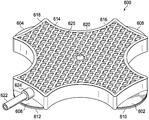
이해할 수 있는 바와 같이, 복수의 부착-베이스 부재들 및 복수의 연결 부재들의 대안적인 부재들은 이동하는 연결부를 제공하고, 이로써, 이동가능하게 연결된다. 이동가능하게 연결된 부재들은, 모듈 감압 상처-폐쇄 시스템(700)이 도 21a의 비-수축 위치에서 도 21b의 수축 위치로 나아가는데에 있어 도움을 줄 수 있다. 또한, 이해할 수 있는 바와 같이, 단지 4 개의 연결 부재들 및 4 개의 부착-베이스 부재들만이 이 도면에서 도시되었지만, 이러한 구성요소들의 수는 보다 크거나 작은 적용에 있어 사용될 수 있다. 예를 들면, 도 22의 모듈 감압 폐쇄 시스템(800)은 매우 보다 큰 시스템 구성을 도시한다.As can be appreciated, the plurality of attachment-base members and alternative members of the plurality of connecting members provide a moving connection, whereby they are movably connected. The movably connected members can help the module decompression wound-
이 예시적인 실시예에서, 모듈 감압 폐쇄 시스템(800)은, 7 개 부착-베이스 부재들(802), 및 감압 계면(804)을 형성하기 위해 변형된 또 다른 것을 가진 복수의 부착-베이스 부재들을 포함한다. 모듈 감압 폐쇄 시스템(800)은 또한, 복수의 연결 부재들을 포함하고, 상기 복수의 연결 부재들은 이 예시적인 실시예에서, 8 개의 연결 부재들(806)을 포함한다. 복수의 부착-베이스 부재들(802) 및 복수의 연결 부재들(806)은 내부 공간(810)을 정의하는 원주 벽(808)을 형성하기 위해 이동가능하게 연결된다. 밀봉 수축 부재(812)는 내부 공간(810) 내에 위치하고, 복수의 부착-베이스 부재들(802)에 적어도 연결된다. 감압이 감압 계면(804) 상의 감압 계면(814)을 통하여 공급될 시에, 감압은 밀봉 수축 부재(812)가 수축되도록 하고, 각각의 복수의 부착-베이스 부재들(802)을 중심 부분을 향해 잡아당긴다. 이로써, 폐쇄력이 제공된다.In this exemplary embodiment, the modular pressure reducing
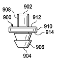
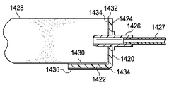
이제, 도 23a 및 23b를 참조하면, 감압 커넥터(900)의 일 예시적인 실시예가 제시된다. 감압 커넥터(900)는 2 개의 서로 다른 구획들 또는 영역들을 유체적으로 연결시키기 위해 동작가능하다. 도 23a 및 23b의 예시적인 실시예에서, 감압 커넥터(900)는 제 1 말단(902) 및 제 2 말단(904)을 가진다. 입구 부분(906)은 제 2 말단(904) 상에서 형성된다. 입구 부분(906)은 다양한 물질, 예를 들면, 밀봉 부재들 및 매니폴드들을 통해 삽입을 용이하게 하는 역 원뿔형 섹션으로서 형상화될 수 있다. 제 1 말단(902) 상에서, 복수의 풀루트들(flutes)(908)은 유체 유동을 용이하게 하기 위해 위치될 수 있다. 플랜지 부분(flange portion)(910)은 제 1 말단(902) 및 제 2 말단(904) 사이에서 형성될 수 있다. 플랜지 부분(910)은 제 1 표면(912) 및 제 2 표면(914)을 가진다. 대안적인 실시예에서, 제 1 말단(902)은 또한, 밀봉 부재 또는 다른 물질을 통하여 완만한 입구(easy entry)로 형상화되고, 구성될 수 있다. 2 개의 서로 다른 예시적인 감압 커넥터(900)의 적용은 도 24a 및 24b에 도시된다.Referring now to FIGS. 23A and 23B, one exemplary embodiment of a pressure
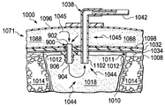
이제, 도 24a를 참조하면, 감압 상처-폐쇄 및 치료 시스템(1000)의 부분이 제시된다. 감압 상처-폐쇄 및 치료 시스템(1000)은 도 1의 표면-상처 폐쇄 서브시스템(60)에 대해 매우 유사하다. 매니폴드(1018)는 체강, 예를 들면, 복강(1010) 내에 위치되어, 감압 치료를 제공하는데 도움을 준다. 매니폴드(1018)는 피하 조직(1014) 및 표면 상처(1011)에 근접하게 위치된 것으로 도시된다.Referring now to FIG. 24A, a portion of a decompression wound-closure and
밀봉 부재(1032)는 복강(1010) 및 표면 상처(1011) 상의 환자의 표피(1008)에 위치된다. 표면 상처는 상처 에지들(1012)을 가진다. 밀봉 부재(1032)는 접착제(1034)를 가지고, 상기 접착제(1034)는 표피(1008)에 공기압 밀봉을 형성하는데 도움을 준다. 적용된 밀봉 부재(1032)는 복강(1010) 상에서 공기압 밀봉을 형성한다.The sealing
상처-폐쇄 장치 또는 서브시스템의 부분(1071) 또한 제시된다. 부분(1071)은 밀봉 수축 부재(1088)의 부분을 포함한다. 밀봉 수축 부재(1088)는 제 1 밀봉 부재(1096) 및 제 2 밀봉 부재(1098)에 의해 적어도 부분적으로 밀봉된다. 밀봉 수축 부재(1088)는 적어도 특정 부분에서, 환자의 표피(1008)에 부착된다. 감압이 밀봉 수축 부재(1088)의 내부에 공급될 시에, 밀봉 수축 부재(1088)는 수축되고, 이로 인해, 중심 부분을 향해 잡아 당겨질 수 있고, 표면 상처(1011)에 전달되는 폐쇄력을 일으킨다.Also shown is
도 24a 및 24b의 예시적인 실시예들에서, 감압은 감압원에 의해 감압 도관(1042)으로 공급된다. 감압 도관(1042)은 감압 계면(1038)에 유체적으로 연결되고, 상기 감압 계면은 연장 부분(1102)을 가진다. 도 24a의 실시예에서, 연장 부분(1102)은 밀봉 부재(1032)를 통하여 매니폴드(1018)로 연장된다. 이로써, 감압은 매니폴드(1018)로 전달되고, 화살표들(1044)로 제시된 바와 같이, 유체를 연장 부분(1102)을 향하여 잡아당긴다. 이 실시예에서, 감압 커넥터(900)는 추가된다. 감압 커넥터(900)는 밀봉 수축 부재(1088)의 내부 내의 제 1 말단(902) 및 매니폴드(1018) 내의 제 2 말단(904)으로 배치된다. 이로 인해, 감압 커넥터(900)는 밀봉 수축 부재(1088)의 내부를 매니폴드(1018)에 유체적으로 연결시킨다. 이로 인해, 감압은 감압 계면(1038)에서 매니폴드(1018)로, 그리고 밀봉 수축 부재(1088)의 내부로 전달된다. 감압 커넥터(900)를 통하여 전달된 감압은 화살표들(1045)로 제시된 바와 같이, 밀봉 수축 부재(1088) 내에서 유체를 잡아당긴다.In the exemplary embodiments of FIGS. 24A and 24B, the reduced pressure is supplied to the reduced
감압 커넥터(900)의 제 1 표면(912)은 밀봉 부재(1032)에 인접하고, 제 2 표면(914)은 매니폴드(1018)에 인접한다. 감압 커넥터(900)는 다수의 방식으로 배치될 수 있다. 예를 들면, 도 17a를 참조하면, 감압 커넥터(900)는 수축 부재(616)의 셀, 예를 들면, 셀(625) 상에 위치될 수 있고, 그 위에 있는 밀봉 부재를 통하여 밀릴 수 있다. 입구 부분(906)은 입구를 용이하게 하기 위해 형성된다. 그 위의 밀봉 부재는 삽입된 후에 자체-밀봉(self-seal)이 되어야 하지만, 그러나 물질을 밀봉하는 추가적인 부분은 또한 삽입점 상에서 추가될 수 있다. 삽입 동안에, 감압 커넥터(900)는, 제 2 표면(914)이 제 2(제시된 배향으로의 하부) 밀봉 부재(1098)에 인접하고, 입구 부분(906)이 수축 부재(616) 외부로 연장될 때까지 밀봉 수축 부재(616)로 밀리게 된다. 이제, 주로 도 24a를 참조하여, 유사한 방식으로, 이때 입구 부분(906)은 밀봉 부재(1032)를 통하여 매니폴드(1018)로 삽입될 수 있다. 앞서 명시된 바와 같이, 다수의 접근법들은 감압 커넥터(900)를 배치시키기 위해 취해질 수 있고, 감압 커넥터(900)는 서로 다른 많은 구성을 취할 수 있지만, 배치된 감압 커넥터(900)는 기능적으로, 밀봉 수축 부재(1088) 및 매니폴드(1018)의 유체 연결을 제공한다.The
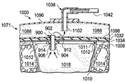
이제, 도 24b를 참조하면, 또 다른 대안물이 제시된다. 도 24b의 실시예에서, 감압 계면(1038)의 연장 부분(1102)은 밀봉 수축 부재(1088) 내에서 종결되고, 밀봉 수축 부재(1088) 내에서 감압을 전달한다. 감압 커넥터(900)는 이전에 제시된 바와 같이 동일한 방식으로 배치되지만, 그러나 이제 감압을 매니폴드(1018)에 전달한다. 즉, 유체는 매니폴드(1018)를 통하여, 감압 커넥터(900)를 통하여, 밀봉 수축 부재(1088)의 내부를 통하여, 감압 계면(1038)의 연장 부분(1102)으로, 그 후에 감압 도관(1042)을 통하여 끌리게 된다.Referring now to FIG. 24B, another alternative is presented. In the embodiment of FIG. 24B, the
이제, 도 25-27을 참조하면, 표면-상처 폐쇄 서브시스템(60)의 또 다른 예시적인 실시예에 적합한 모듈 감압 폐쇄 시스템(1200)의 또 다른 예시적인 실시예가 제시된다. 모듈 감압 폐쇄 시스템(1200)은 간격 부재, 예를 들면, 가요성 스트랩(strap)(1202)을 포함하고, 상기 가요성 스트랩은 도 25의 직선 위치에서 도시되고, 도 27의 폐쇄형 루프(1204)로 형성된다. 가요성 스트랩(1202)은, 환자의 복부 상에서 개방된 것과 같은 표면 상처(1206) 주위에서 폐쇄형 루프(1204)로 형성될 수 있다. 복수의 모듈 폐쇄 부재들(1208)은 가요성 스트랩(1202)에 선택적으로 연결된다. 가요성 스트랩(1202) 상의 복수의 모듈 폐쇄 부재들에 포함된 모듈 폐쇄 부재들(1208)의 수는 표면 상처(1206)를 둘러싸기에 필요한 폐쇄형 루프(1204)의 크기에 의해 판별된다. 이로써, 도 27의 표면 상처(1206)를 덮기 위해, 8 개의 모듈 폐쇄 부재들(1208)은 가요성 스트랩(1202) 상에서 포함된다. 가요성 스트랩(1202)이 참조되면서, 표면 상처(1206) 주위의 간격 관계로 모듈 폐쇄 부재들(1208)을 유지시키는 간격 부재는 사용될 수 있다. 예를 들면, 간격 부재는, 모듈 폐쇄 부재들(1208)을 간격 관계로 유지시키는 하나 이상의 타이 와이어들(tie wires) 또는 모듈 폐쇄 부재들(1208)을 간격 관계로 유지시키는 모듈 폐쇄 부재들(1208)의 상부 상에 위치된 가요성 접착제 막일 수 있다.Referring now to FIGS. 25-27, another exemplary embodiment of a modular pressure reducing
도 25를 다시 주로 참조하면, 각각의 모듈 폐쇄 부재들(1208)은 제 1 말단(1210) 및 제 2 말단(1212)을 가진다. 연결 부재(1214)는 각각의 모듈 폐쇄 부재(1208)의 제 1 말단(1210)에 연결된다. 도 25의 예시적인 실시예에서, 각각의 연결 부재(1214)는 부착 루프(attachment loop)(1216)를 포함하고, 상기 부착 루프를 통하여 가요성 스트랩(1202)이 위치될 수 있다. 부착 루프들(1216)은 각각의 모듈 폐쇄 부재(1208)가 가요성 스트랩(1202)을 따라 원하는 장소에서 위치되도록 한다. 각각의 부착 루프(1216)의 부분은 가요성 스트랩(1202) 상의 원하는 위치에서 연결 부재(1214)를 유지시키는데 도움을 주기 위해 복수의 스트랩 개방부들(1218) 중 하나와 연결될 수 있다.Referring back mainly to FIG. 25, each
이제, 주로 도 26을 참조하면, 제 2 감압 계면(1226)은 연결 부재(1214)에 연결되는 것으로 도시된다. 감압 도관(1227)은 감압을 제 2 감압 계면(1226)에 제공하기 위해 제 2 감압 계면(1226)에 유체적으로 연결된다. 제 2 감압 계면(1226)은 감압을 밀봉 수축 부재(1228)에 전달하고, 가요성 스트랩(1202)에 대해 연결 부재(1214)를 적당하게 유지시키기 위해 핀의 기능을 할 수 있다. 제 2 감압 계면(1226)은 연결 부재(1214)의 개방부를 통해, 부착 루프(1216)를 통해, 가요성 스트랩(1202)을 통해, 밀봉 수축 부재(1228)로 연장될 수 있다. 도 26에서, 도시된 바와 같이, 밀봉 수축 부재(1228)는 접착제 층(1229)에 의해 베이스(1231)에 유지될 수 있다. 이와 유사하게, 밀봉 수축 부재(1228)의 주변 에지(1233)는 접착제 층(1235)에 의해 연결 부재(1214)의 벽(1251)에 유지될 수 있다. 이 방식으로, 감압은 모듈 폐쇄 부재(1208)로 공급될 수 있고, 특히 밀봉 수축 부재(1228)로 공급될 수 있다. 도 28 및 29는 이하에 추가로 기술된 바와 같이, 감압을 밀봉 수축 부재(1228)에 제공하는 대안적인 방식을 제시한다.Referring now primarily to FIG. 26, the second reduced
밀봉 수축 부재(1228)는 수축 부재(196(도 1), 616(도 17a), 및 722(도 21a))와 동일한 물질 또는 유사한 물질로 구현된다. 밀봉 수축 부재(1228)는 밀봉 수축 부재(1228) 주위에서 공기압 밀봉을 형성하기 위해 밀봉된다. 접착제 층(1229)은 밀봉 수축 부재(1228)를 베이스(1231)에 유지시키기 위해 사용될 수 있다. 접착제 층(1235)은 또한, 밀봉 수축 부재(1228)의 주변 에지(1233)를 벽(1251)에 부착시키기 위해 사용될 수 있다.
모듈 폐쇄 부재(1208)의 다른 말단에서, 부착 부재들(1220)은 모듈 폐쇄 부재들(1208)의 제 2 말단들(1212) 각각에 연결될 수 있다. 도 25를 다시 주로 참조하면, 각각의 부착 부재들(1220)은 베이스(1222) 및 벽(1224)으로 형성될 수 있다. 접착제 층은 밀봉 수축 부재(1228)를 베이스(1222)에 유지시키기 위해 사용될 수 있다. 접착제 층은 또한, 밀봉 수축 부재를 벽(1224)에 유지시키기 위해 사용될 수 있다. 접착제는 베이스(1222)의 내부-방향 측(1236)을 환자의 표피에 유지시키기 위해 사용될 수 있다.At the other end of the
이제, 도 28을 주로 참조하면, 모듈 감압 폐쇄 시스템(1200)의 부분으로 사용될 수 있는 대안적인 감압 계면(1327)이 제시된다. 감압은 연결 부재를 통하여 밀봉 수축 부재(1308)로 제공될 수 있다. 예를 들면, 모듈 폐쇄 부재는 선택적으로 가요성 스트랩(1302)에 부착되는 연결 부재(1316)를 가질 수 있다. 접착제(1330)는 밀봉 수축 부재(1308)를 연결 부재(1316)에 유지시키기 위해 사용될 수 있다. 연결 부재(1316)는 벽(1324) 및 베이스(1322)를 가질 수 있다. 감압 계면(1327)은 베이스(1322) 상에서 형성될 수 있고, 밀봉 수축 부재(1308)에 들어가도록 구성된다. 감압 계면(1327)은 매니폴드(1380)와 맞물리도록 치수화되고 구성되고, 상기 매니폴드는 유체를 감압원으로 전달하거나, 감압원과 유체적으로 연결된다. 감압은 매니폴드(1380)로 전달된다.Referring now primarily to FIG. 28, an
이제, 도 29를 참조하면, 베이스 부분(1422) 및 벽(1424)을 가진 부착 부재(1420)는 대안적인 감압 계면(1426)과 함께 도시된다. 감압 계면(1426)은 벽(1424)을 통하여 형성된다. 감압 도관(1427)은 감압원에서 감압 계면(1426)으로 감압을 전달한다. 감압 계면(1426)은 감압을 밀봉 수축 부재(1428)로 전달한다. 밀봉 수축 부재(1428)는 부착 장치, 예를 들면, 접착제(1430)에 의해 베이스(1422)에 유지될 수 있다. 베이스(1422)는 부착 장치(1432), 예를 들면, 접착제(1436)에 의해 환자의 표피에 유지될 수 있다. 밀봉 수축 부재(1428)는 또한, 부착 장치(1432), 예를 들면, 접착제(1434)에 의해 벽(1424)에 유지될 수 있다.Referring now to FIG. 29, an
도 27을 다시 참조하면, 동작 시, 모듈 감압 폐쇄 시스템(1200)은 의료 제공자에 의해 사용될 수 있고, 상기 의료 제공자는 우선 표면 상처(1206)의 크기를 평가하고, 상처의 크기에 적당한 모듈 폐쇄 부재들(1208)의 수를 판별한다. 룩업 테이블(lookup table)은 표면 상처(1206)의 원주의 직선 계측(linear measurement)에 기초한 수를 제안하기 위해 제공될 수 있다. 그 후에, 원하는 복수의 모듈 폐쇄 부재들(1208)을 이루는 적당한 수는 가요성 스트랩(1202)에 선택적으로 연결된다. 가요성 스트랩(1202)은 표면 상처(1206) 주위에서 폐쇄형 루프(1204)로 형성되고, 표면 상처(1206)의 주변 에지들의 내측에 배치되는 것이 바람직하다. 폐쇄형 루프(1204)는 다수의 수단, 예를 들면, 래치트(ratchet), 스냅(snap), 파스터너(fastener)를 사용한 루프로서, 가요성 스트랩(1202), 래치트 타이들, 가요성 페그(peg) 및 슬롯(slot) 부재들 등 상에 고정된다. 그 후에, 각각의 복수의 부착 부재들(1220)은 표면 상처(1206)의 에지에 근접한 환자의 표피에 부착된다. 이전과 같이, 각각의 복수의 부착 부재들(1220)이 표피에 부착되는 설명은, 부착 부재(1220)가 감압 치료에 사용되는 밀봉 부재의 상부 상에 부착된다는 것을 포함할 수 있다. 감압이 감압 도관(1227)을 통하여 각각의 모듈 폐쇄 부재(1208)의 감압 계면(1226)에 공급될 시에, 폐쇄력은 화살표들(1240)로 제시된 바와 같이 일어난다.Referring back to FIG. 27, in operation, the modular
폐쇄형 루프(1204)는, 감압 치료 시스템의 부분에 감압을 공급하기 위해 사용될 수 있는 감압 계면(1242)을 손쉽게 수용하는 루프의 중간에 개방 영역을 제공한다(예를 들면, 도 1의 서브시스템(58)을 참조).
일반적인 동작Common behavior
도 1을 주로 참조하면, 개방된 복강(32)을 치료하는 하나의 예시적인 접근법에 따라서, 의료 제공자는 개방 공동 치료 서브시스템(52)의 부분으로서 개방 공동 치료 장치(50)를 놓을 수 있다. 개방 공동 치료 장치(50)는 특별한 적용에 맞추기 위해 초기에 치수화될 수 있다. 예를 들면, 도 6을 참조하면, 개방 공동 치료 장치(202)는 드레싱을 적당하게 치수화시키기 위해 조작 영역들(212)을 통하여 시각적 표시부(214)를 따라 절단될 수 있다. 도 1을 다시 참조하면, 개방 공동 치료 장치(50)가 적당하게 치수화되면, 개방 공동 치료 장치(50)는 복강(32) 내에, 그리고 복부 내용물(46)의 상부 상에 위치된다. 개방 공동 치료 장치(50)의 캡슐화된 레그 부재들(90)은 원하는 위치, 예를 들면, 환자의 간 등 뒤에 있는 대장측 홈들(92, 94), 골반 안에서 덮이고 작동될 수 있다.Referring primarily to FIG. 1, in accordance with one exemplary approach to treating an open
의료 제공자는 개방 공동 치료 장치(50)의 제 1 측(또는 제시된 배향의 상부) 상에 깊은-조직 폐쇄 장치(54)를 위치시킬 수 있다. 깊은-조직 폐쇄 서브시스템(56)의 부분인 깊은-조직 폐쇄 장치(54)는 깊은-조직 상처를 수용하기 위해, 원하는 크기로 깊은-조직 폐쇄 장치(54)를 절단함으로써, 치수화될 필요가 있다. 의료 제공자는 깊은-조직 폐쇄 장치(54)의 제 1 측(또는 제시된 배향의 상부) 상에 조직, 즉, 근막(36)의 층들을 위치시키는데 도움을 줄 수 있다. 매니폴드(64)는 복강(32) 내에, 그리고 깊은-조직 폐쇄 장치(54)의 부분의 상부 상에 삽입될 수 있다.The healthcare provider may position the deep-
그 후에, 밀봉 부재(66)는 복강(32)의 개방부 상에, 그리고 표피(44) 상에 위치될 수 있어서, 공기압 밀봉을 제공한다. 이는 해제가능한 백킹을 접착제(70)로부터 제거함으로써 행해질 수 있고, 접착제(70)를 표피(44)에 위치시킨다. 그 후에, 추가적인 폐쇄력 및 지지를 제공하는데 도움을 주기 위해, 표면-상처 폐쇄 서브시스템(60)은 적용될 수 있다. 표면-상처 폐쇄 서브시스템의 가능한 다수의 실시예들은 사용될 수 있다. 추가로, 다양한 다른 서브시스템들 및 대안물들은 감압 복부 치료 시스템(30)의 부분으로서 사용될 수 있다.Thereafter, the sealing
도 1을 여전히 참조하면, 제 1 부착 부재(186)는 표면-상처 에지들(182)의 일 측 상에 적용될 수 있고, 제 2 부착 부재(193)는 일반적으로 제 1 부착 부재(186)와 반대인 위치에서, 그리고 표면-상처 에지(182)의 타 측 상에서 적용될 수 있다. 부착 부재들(186 및 193)은 해제가능한 백킹을 접착제 층, 예를 들면, 제 1 부착 부재(186) 상의 제 1 접착제(192)로부터 해제가능한 백킹을 제거함으로써, 부착될 수 있고, 접착제를 밀봉 부재(66)에 적용시킬 수 있다.Still referring to FIG. 1, the
그 후에, 감압 계면(72)의 부분은 표면 표면-상처 폐쇄 서브시스템(60)의 개방부(187)에, 그리고 매니폴드(64)에 위치될 수 있다. 제 1 감압 전달 도관(76)은 감압 계면(72) 및 감압 공급 서브시스템(62)에 유체적으로 연결될 수 있고, 상기 감압 공급 서브시스템(62)은 감압을 제 1 감압 전달 도관(76)으로 전달한다. 표면 표면-상처 폐쇄 서브시스템(60)은, 제 2 감압 전달 도관(195)에 유체적으로 연결된 적어도 하나의 제 2 감압 계면(194)을 포함한다. 제 2 감압 전달 도관(195)은, 감압을 제 2 감압 전달 도관(195)에 전달하는 감압 공급 서브시스템(62)에 유체적으로 연결된다.Thereafter, a portion of the pressure
그 후에, 의료 제공자는 감압 공급 서브시스템(62)을 작동시킬 수 있고, 상기 감압 공급 서브시스템은 감압(제 1 감압 또는 치료-감압)을 감압 치료 서브시스템(58)에, 특히 매니폴드(64)에 전달한다. 이 감압은 또한, 개방 공동 치료 장치(50) 및 깊은-조직 폐쇄 장치(54)에 전달된다. 도 28의 실시예에 의해 제시된 바와 같이, 감압은 또한 매니폴드(64)에 의해 표면-상처 폐쇄 서브시스템(60)에 공급될 수 있지만, 그러나, 도 1의 예시적인 실시예에서, 감압(제 2 감압 또는 폐쇄 감압)은 제 2 감압 전달 도관(195)에 의해 밀봉 수축 부재(196)에 공급될 수 있으며, 밀봉 수축 부재(196)가 수축되도록 하고 표피(44)의 표면-상처 에지들(182)을 함께 잡아당기도록 한다.Thereafter, the healthcare provider can operate the
감압 복부 치료 시스템(30), 특히, 개방 공동 치료 장치(50)는, 복부 내용물(46)에 접착됨 없이 복강(32) 및 조직 부위(34)로부터 복수 및 다른 유체를 제거하는데 도움을 준다. 감압 복부 치료 시스템(30)은, 근막 "롤링(rolling)" 없이, 또는 다른 문제점을 일으킴 없이, 근막(36)에 상처의 구멍을 뚫을 필요 없이, 근막(36)을 폐쇄시키는데 도움을 주기 위해 깊은-조직 폐쇄 서브시스템(56)을 이용한다. 감압 복부 치료 시스템(30)은 매니폴드(64)를 포함한 감압 치료 서브시스템(58)으로 복강(32) 내에 감압 치료를 제공하는데 일반적으로 도움을 준다. 감압 복부 치료 시스템(30)은 또한, 표면-상처 폐쇄 서브시스템(60)을 사용함으로써, 표피(44)의 표면 상처(180)를 폐쇄시키는데 도움을 준다.The decompression
비록 본 발명 및 그 장점이 특정한 예시인 비제한적인 실시예에 대한 설명으로 개시되었으나, 첨부된 청구항에 의해 정의되는 본 발명의 범위로부터 벗어나지 않고, 다양한 변경, 대체, 치환 및 대안이 이루어질 수 있다는 것을 이해해야 한다. 일 실시예와 함께 기술되는 특징이 다른 실시예에 적용가능할 수도 있다는 것을 인식할 것이다.Although the invention and its advantages have been disclosed in the description of a non-limiting embodiment, which is a specific illustration, various changes, substitutions, substitutions and substitutions may be made without departing from the scope of the invention as defined by the appended claims. You have to understand. It will be appreciated that the features described with one embodiment may be applicable to other embodiments.
Claims (43)
환자의 근막 상의 깊은-조직 상처 상에 폐쇄력을 가하는 깊은-조직 폐쇄 장치(상기 깊은-조직 폐쇄 장치는 수축성 매트릭스를 가짐); 및
환자의 복강에 감압 치료를 제공하는 감압 치료 서브시스템을 포함하는 것을 특징으로 하는 복부 치료 시스템.An open cavity treatment device for providing decompression treatment in proximity to the abdominal contents of a patient, the open cavity treatment device having a plurality of encapsulated leg members;
A deep-tissue closure device that exerts a closing force on a deep-tissue wound on the patient's fascia, wherein the deep-tissue closure device has a contractile matrix; And
And a decompression therapy subsystem providing decompression therapy to the abdominal cavity of the patient.
환자의 표피 상의 표면 상처 상에 폐쇄력을 제공하는 표면-상처 폐쇄 서브시스템을 더 포함하는 것을 특징으로 하는 복부 치료 시스템.The method of claim 1,
And a surface-wound closure subsystem providing closure force on the surface wound on the epidermis of the patient.
환자의 표피 상의 표면 상처 상에 폐쇄력을 제공하는 표면-상처 폐쇄 서브시스템; 및
상기 개방 공동 치료 장치, 상기 깊은-조직 폐쇄 장치, 상기 감압 치료 서브시스템, 및 상기 표면-상처 폐쇄 서브시스템에 사용되는 감압을 일으키기 위해 동작가능한 감압 공급 서브시스템을 더 포함하는 것을 특징으로 하는 복부 치료 시스템.The method of claim 1,
A surface-wound closure subsystem that provides a closure force on the surface wound on the epidermis of the patient; And
And further comprising a decompression supply subsystem operable to effect decompression used in the open cavity treatment device, the deep-tissue closure device, the decompression treatment subsystem, and the surface-wound closure subsystem. system.
상기 수축성 매트릭스는 복수의 셀들을 포함하고,
상기 복수의 셀들은 감압을 받지 않을 시의 제 1 부피(V1), 감압을 받을 시의 제 2 부피(V2)를 가지고, V1>V2인 것을 특징으로 하는 복부 치료 시스템.The method of claim 1,
The shrinkable matrix comprises a plurality of cells,
Wherein said plurality of cells have a first volume (V 1 ) without decompression, a second volume (V 2 ) with decompression, and wherein V 1 > V 2 .
상기 수축성 매트릭스는 복수의 셀들을 포함하고,
상기 복수의 셀들은 가요성 측 벽들을 가지고,
상기 측 벽들은 감압을 받을 시에 서로 보다 가까이 이동하는 것을 특징으로 하는 복부 치료 시스템.The method of claim 1,
The shrinkable matrix comprises a plurality of cells,
The plurality of cells have flexible side walls,
And the side walls move closer to each other upon decompression.
상기 수축성 매트릭스는 복수의 셀들을 포함하고,
상기 복수의 셀들은 깊은 조직에 유체를 전달하는 제 1 개구부, 및 감압을 수용하는 제 2 복수의 개구부들을 가지는 것을 특징으로 하는 복부 치료 시스템.The method of claim 1,
The shrinkable matrix comprises a plurality of cells,
Wherein said plurality of cells has a first opening for delivering fluid to deep tissue and a second plurality of openings for receiving a reduced pressure.
환자의 표피 상의 표면 상처 상에 폐쇄력을 제공하는 표면-상처 폐쇄 서브시스템;
상기 개방 공동 치료 장치, 상기 깊은-조직 폐쇄 장치, 상기 감압 치료 서브시스템, 및 상기 표면-상처 폐쇄 서브시스템에 사용되는 감압을 일으키기 위해 동작가능한 감압 공급 서브시스템
을 더 포함하고,
상기 복수의 캡슐화된 레그 부재들은 비-접착성 드레이프에 연결되고, 각각의 복수의 캡슐화된 레그 부재들은 레그 매니폴드 부재를 구비한 내부 부분을 가지고, 상기 내부 부분으로 유체가 흐르기 위해 동작가능한 개창부들로 형성되고,
상기 비-접착성 드레이프 및 상기 복수의 캡슐화된 레그 부재들에 연결된 중심 연결 부재를 더 포함하고, 상기 중심 연결 부재는 연결 매니폴드 부재를 가지고, 각각의 레그 매니폴드 부재는 상기 연결 매니폴드 부재에 유체를 전달하는 것을 특징으로 하는 복부 치료 시스템.The method of claim 1,
A surface-wound closure subsystem that provides a closure force on the surface wound on the epidermis of the patient;
Decompression supply subsystem operable to cause decompression used in the open cavity treatment device, the deep-tissue closure device, the decompression treatment subsystem, and the surface-wound closure subsystem.
More,
The plurality of encapsulated leg members are connected to a non-adhesive drape, each of the plurality of encapsulated leg members having an inner portion with a leg manifold member, the openings operable for fluid to flow into the inner portion. Formed into,
Further comprising a center connecting member connected to the non-adhesive drape and the plurality of encapsulated leg members, wherein the center connecting member has a connecting manifold member, each leg manifold member is connected to the connecting manifold member. An abdominal treatment system, comprising delivering a fluid.
상기 깊은-조직 폐쇄 장치는, 제 1 측 및 제 2 내부-방향 측을 가진 수축성 매트릭스를 포함하고,
상기 제 1 측은 복수의 개구부들로 형성되고,
상기 제 2 내부-방향 측은 복수의 셀들로 형성되고,
상기 수축성 매트릭스는 환자의 근막에 근접하게 배치되어 감압을 받을 시에 수축되도록 동작가능한 것을 특징으로 하는 복부 치료 시스템.The method of claim 3, wherein
The deep-tissue closure device comprises a contractile matrix having a first side and a second inner-direction side,
The first side is formed of a plurality of openings,
The second inner-direction side is formed of a plurality of cells,
And the contractile matrix is placed proximal to the patient's fascia and operable to contract upon decompression.
상기 감압 치료 서브시스템은:
환자의 복강 내에 배치되고 환자의 복강 내에 감압을 집배시키기 위해(manifold) 동작가능한 매니폴드;
환자의 표피의 부분 상에 배치되고 환자의 복강 상에 공기압 밀봉을 형성하기 위해 동작가능한 밀봉 부재;
감압 전달 도관; 및
상기 밀봉 부재에 연결되고 상기 감압 전달 도관에 유체적으로 연결되는 감압 계면(상기 감압 계면은 상기 감압 전달 도관에서 상기 매니폴드로 감압을 전달하기 위해 동작가능함)을 포함하는 것을 특징으로 하는 복부 치료 시스템.The method of claim 3, wherein
The decompression treatment subsystem is:
A manifold disposed in the abdominal cavity of the patient and operable to collect decompression in the abdominal cavity of the patient;
A sealing member disposed on a portion of the epidermis of the patient and operable to form an air pressure seal on the abdominal cavity of the patient;
Reduced pressure delivery conduits; And
An abdominal therapy system connected to the sealing member and fluidly connected to the decompression delivery conduit, the decompression interface operable to deliver decompression from the decompression delivery conduit to the manifold. .
상기 표면-상처 폐쇄 서브시스템은:
표면 상처의 에지에 근접하여 환자의 표피의 제 1 부분에 해제가능하게 부착시키는 제 1 부착 부재;
표면 상처의 에지에 근접하여 환자의 표피의 제 2 부분에 해제가능하게 부착시키는 제 2 부착 부재(상기 제 1 부착 부재와 상기 제 2 부착 부재는 떨어져 있음);
상기 제 1 부착 부재 및 상기 제 2 부착 부재에 연결되고, 감압을 받는 위치에 놓일 시에 수축되도록 동작가능한 밀봉 수축 부재
를 포함하고,
상기 밀봉 수축 부재에 감압이 공급될 시에 상기 제 1 부착 부재와 상기 제 2 부착 부재 사이에는 폐쇄력이 일어나는 것을 특징으로 하는 복부 치료 시스템.The method of claim 3, wherein
The surface-wound closure subsystem is:
A first attachment member releasably attaching to a first portion of the epidermis of the patient proximate the edge of the surface wound;
A second attachment member releasably attaching to a second portion of the epidermis of the patient proximate the edge of the surface wound, wherein the first attachment member and the second attachment member are apart;
A sealing contraction member connected to the first attachment member and the second attachment member and operable to retract upon being placed in a position under reduced pressure
Including,
And a closing force occurs between the first attachment member and the second attachment member when a reduced pressure is supplied to the sealing contraction member.
상기 수축성 매트릭스는, 감압이 감압원에 의해 공급될 시에, 상기 수축성 매트릭스의 제 1 측에 인접하여 환자의 근막 상에 그립력을 일으키고 비수축 위치에서 수축 위치로 이동하기 위해 동작가능한 것을 특징으로 하는 복부 치료 시스템.The method of claim 8,
The contractile matrix is operable to cause a grip force on the patient's fascia adjacent to the first side of the contractile matrix and move from the non-constricted position to the retracted position when the decompression matrix is supplied by the decompression source. Abdominal therapy system.
상기 수축성 매트릭스는, 감압이 감압원에 의해 공급될 시에, 상기 수축성 매트릭스의 제 1 측에 인접하여 환자의 근막 상에 그립력을 일으키고 깊은-조직 상처 상에 폐쇄력을 발생시키기 위해 동작가능한 것을 특징으로 하는 복부 치료 시스템.The method of claim 8,
The contractive matrix is operable to cause a grip force on the patient's fascia and a closure force on a deep-tissue wound when the decompression matrix is supplied by the decompression source, adjacent to the first side of the contractile matrix. Abdominal therapy system.
수축성 매트릭스는 벌집 매트릭스로 형성된 것을 특징으로 하는 복부 치료 시스템.The method of claim 8,
The abdominal treatment system, characterized in that the contractile matrix is formed of a honeycomb matrix.
상기 깊은-조직 폐쇄 장치는, 제 1 측 및 제 2 내부-방향 측을 가진 수축성 매트릭스를 포함하고,
상기 제 2 내부-방향 측은 복수의 셀들 및 복수의 세포내 개구부들(inter-cellular apertures)로 형성되고,
상기 수축성 매트릭스는 깊은-조직 상처에 근접하여 배치되는 것을 특징으로 하는 복부 치료 시스템.The method of claim 8,
The deep-tissue closure device comprises a contractile matrix having a first side and a second inner-direction side,
The second inward-facing side is formed of a plurality of cells and a plurality of inter-cellular apertures,
Wherein the contractile matrix is disposed proximate to a deep-tissue wound.
상기 수축성 매트릭스는, 감압이 감압원에 의해 공급될 시에, 상기 수축성 매트릭스의 제 1 측에 인접하여 환자의 근막 상에 그립력을 일으키고 비수축 위치에서 수축 위치로 이동하기 위해 동작가능한 것을 특징으로 하는 복부 치료 시스템.The method of claim 14,
The contractile matrix is operable to cause a grip force on the patient's fascia adjacent to the first side of the contractile matrix and move from the non-constricted position to the retracted position when the decompression matrix is supplied by the decompression source. Abdominal therapy system.
상기 수축성 매트릭스는, 감압이 감압원에 의해 공급될 시에, 상기 수축성 매트릭스의 제 1 측에 인접하여 환자의 근막 상에 그립력을 일으키고 깊은-조직 상처 상에 폐쇄력을 발생시키기 위해 동작가능한 것을 특징으로 하는 복부 치료 시스템.The method of claim 15,
The contractive matrix is operable to cause a grip force on the patient's fascia and a closure force on a deep-tissue wound when the decompression matrix is supplied by the decompression source, adjacent to the first side of the contractile matrix. Abdominal therapy system.
상기 수축성 매트릭스는 벌집 매트릭스로 형성된 것을 특징으로 하는 복부 치료 시스템.The method of claim 11,
Wherein the contractile matrix is formed of a honeycomb matrix.
상기 복수의 캡슐화된 레그 부재들의 캡슐화된 레그 부재 각각은:
개창부들로 형성된 제 1 레그 캡슐형 부재;
개창부들로 형성된 제 2 레그 캡슐형 부재;
를 포함하고,
상기 레그 매니폴드 부재는 제 1 측, 제 2 내부-방향 측, 제 1 측면 에지, 및 제 2 측면 에지를 가지고,
상기 제 1 레그 캡슐형 부재는 상기 레그 매니폴드 부재의 제 1 측에 근접하여 배치되고,
상기 제 2 레그 캡슐형 부재는 상기 레그 매니폴드 부재의 제 2 내부-방향 측에 근접하여 배치되고, 그리고
상기 제 1 레그 캡슐형 부재 및 상기 제 2 레그 캡슐형 부재는 상기 레그 매니폴드 부재의 제 1 측면 에지 및 제 2 측면 에지에 근접하여 연결되는 것을 특징으로 하는 복부 치료 시스템.The method of claim 1,
Each of the encapsulated leg members of the plurality of encapsulated leg members is:
A first leg capsule member formed of openings;
A second leg capsule member formed of openings;
Including,
The leg manifold member has a first side, a second inner-direction side, a first side edge, and a second side edge,
The first leg capsule member is disposed proximate to a first side of the leg manifold member,
The second leg capsule member is disposed proximate a second inner-direction side of the leg manifold member, and
And the first leg capsule member and the second leg capsule member are connected in proximity to the first side edge and the second side edge of the leg manifold member.
상기 복수의 캡슐화된 레그 부재들의 캡슐화된 레그 부재 각각은 복수의 레그 모듈들로 형성된 캡슐화된 레그 부재를 포함하는 것을 특징으로 하는 복부 치료 시스템.The method of claim 1,
And wherein each of the encapsulated leg members of the plurality of encapsulated leg members comprises an encapsulated leg member formed of a plurality of leg modules.
상기 비-접착성 드레이프는 크기 눈금을 나타내는 시각적 표시부를 더 포함하는 것을 특징으로 하는 복부 치료 시스템.The method of claim 7, wherein
And said non-adhesive drape further comprises a visual indicator indicative of the size scale.
상기 중심 연결 부재는:
개창부들로 형성되고 주변 에지를 가진 제 1 연결 캡슐형 부재;
개창부들로 형성되고 주변 에지를 가진 제 2 연결 캡슐형 부재
를 포함하고,
상기 제 1 연결 캡슐형 부재의 주변 에지는 상기 제 2 연결 캡슐형 부재의 주변 에지에 연결되되, 상기 연결 매니폴드 부재를 싸기 위해 레그 연결 영역들을 제외시키고 연결되는 것을 특징으로 하는 복부 치료 시스템.The method of claim 7, wherein
The center connecting member is:
A first connecting encapsulated member formed of openings and having a peripheral edge;
Second connecting encapsulated member formed with openings and having a peripheral edge
Including,
A peripheral edge of the first connecting encapsulated member is connected to the peripheral edge of the second connecting encapsulated member, with the exception of leg connecting regions for enclosing the connecting manifold member.
상기 복수의 캡슐화된 레그 부재들의 캡슐화된 레그 부재 각각은:
개창부들로 형성된 제 1 레그 캡슐형 부재;
개창부들로 형성된 제 2 레그 캡슐형 부재;
를 포함하고,
상기 레그 매니폴드 부재는 제 1 측, 제 2 내부-방향 측, 제 1 측면 에지, 및 제 2 측면 에지를 가지고,
상기 제 1 레그 캡슐형 부재는 상기 레그 매니폴드 부재의 제 1 측에 근접하여 배치되고, 상기 제 2 레그 캡슐형 부재는 상기 레그 매니폴드 부재의 제 2 내부-방향 측에 근접하여 배치되고, 그리고 상기 제 1 레그 캡슐형 부재 및 상기 제 2 레그 캡슐형 부재는 상기 레그 매니폴드 부재의 제 1 측면 에지 및 제 2 측면 에지에 근접하여 연결되고,
상기 중심 연결 부재는:
개창부들로 형성되고 주변 에지를 가진 제 1 연결 캡슐형 부재;
개창부들로 형성되고 주변 에지를 가진 제 2 연결 캡슐형 부재
를 포함하고,
상기 제 1 연결 캡슐형 부재의 주변 에지는 상기 제 2 연결 캡슐형 부재의 주변 에지에 연결되되, 상기 연결 매니폴드 부재를 싸기 위해 레그 연결 영역들을 제외시키고 연결되는 것을 특징으로 하는 복부 치료 시스템.The method of claim 7, wherein
Each of the encapsulated leg members of the plurality of encapsulated leg members is:
A first leg capsule member formed of openings;
A second leg capsule member formed of openings;
Including,
The leg manifold member has a first side, a second inner-direction side, a first side edge, and a second side edge,
The first leg capsule member is disposed proximate to a first side of the leg manifold member, the second leg capsule member is disposed proximate a second inner-direction side of the leg manifold member, and The first leg capsule member and the second leg capsule member are connected in proximity to the first side edge and the second side edge of the leg manifold member,
The center connecting member is:
A first connecting encapsulated member formed of openings and having a peripheral edge;
Second connecting encapsulated member formed with openings and having a peripheral edge
Including,
A peripheral edge of the first connecting encapsulated member is connected to the peripheral edge of the second connecting encapsulated member, with the exception of leg connecting regions for enclosing the connecting manifold member.
표면 상처의 에지에 근접하여 환자의 표피의 제 3 부분에 해제가능하게 부착시키는 제 3 부착 부재를 더 포함하고,
상기 제 2 부착 부재는 상기 제 1 및 제 2 부착 부재들과는 떨어져 있고, 그리고
상기 제 3 부착 부재는 상기 밀봉 수축 부재에 연결되는 것을 특징으로 하는 복부 치료 시스템.The method of claim 10,
A third attachment member releasably attaching to a third portion of the epidermis of the patient proximate the edge of the surface wound,
The second attachment member is spaced apart from the first and second attachment members, and
And the third attachment member is connected to the sealing contraction member.
표면 상처의 에지에 근접하여 환자의 표피의 제 4 부분에 해제가능하게 부착시키는 제 4 부착 부재를 더 포함하고,
상기 제 4 부착 부재는 상기 제 1, 제 2, 및 제 3 부착 부재들과는 떨어져 있고, 그리고
상기 제 4 부착 부재는 상기 밀봉 수축 부재에 연결되는 것을 특징으로 하는 복부 치료 시스템.The method of claim 23,
Further comprising a fourth attachment member releasably attaching to a fourth portion of the epidermis of the patient proximate the edge of the surface wound,
The fourth attachment member is spaced apart from the first, second, and third attachment members, and
And the fourth attachment member is connected to the sealing contraction member.
상기 제 1 부착 부재는 제 1 베이스 부재 및 제 1 접착제를 포함하고,
상기 제 2 부착 부재는 제 2 베이스 부재 및 제 2 접착제를 포함하는 것을 특징으로 하는 복부 치료 시스템.The method of claim 10,
The first attachment member comprises a first base member and a first adhesive,
And said second attachment member comprises a second base member and a second adhesive.
상기 밀봉 수축 부재는:
제 1 측 및 제 2 내부-방향 측, 그리고 주변 에지를 가진 수축성 매니폴드 물질;
상기 수축성 매니폴드 물질의 제 1 측에 걸쳐 배치된 제 1 밀봉 부재;
상기 수축성 매니폴드 물질의 제 2 내부-방향 측에 걸쳐 배치된 제 2 밀봉 부재;
상기 수축성 매니폴드 물질의 주변 에지에 걸쳐 배치된 주변 밀봉 장치;
를 포함하고,
상기 제 1 밀봉 부재, 상기 제 2 밀봉 부재, 및 상기 주변 밀봉 장치는 상기 수축성 매니폴드 물질을 공기압으로 밀봉하기 위해 동작가능한 것을 특징으로 하는 복부 치료 시스템.The method of claim 10,
The sealing shrink member is:
Shrinkable manifold material having a first side and a second inner-direction side and a peripheral edge;
A first sealing member disposed over the first side of the shrinkable manifold material;
A second sealing member disposed over the second inner-direction side of the shrinkable manifold material;
A peripheral sealing device disposed over the peripheral edge of the shrinkable manifold material;
Including,
Wherein said first sealing member, said second sealing member, and said peripheral sealing device are operable to seal the contractile manifold material with air pressure.
상기 주변 밀봉 장치는 제 3 밀봉 층을 포함한 것을 특징으로 하는 복부 치료 시스템.The method of claim 26,
And the peripheral sealing device comprises a third sealing layer.
상기 주변 밀봉 장치는 외벽을 포함한 것을 특징으로 하는 복부 치료 시스템.The method of claim 26,
And the peripheral sealing device comprises an outer wall.
상기 제 1 부착 부재는:
제 1 측 및 제 2 내부-방향 측을 가진 제 1 베이스 부재;
상기 제 1 베이스 부재에 연결된 제 1 외벽; 및
상기 제 2 내부-방향 측에 연결된 제 1 접착제를 포함하는 것을 특징으로 하는 복부 치료 시스템.The method of claim 10,
The first attachment member is:
A first base member having a first side and a second inner-direction side;
A first outer wall connected to the first base member; And
And a first adhesive connected to the second inward-facing side.
상기 표면-상처 폐쇄 서브시스템은:
밀봉 수축 부재;
복수의 부착-베이스 부재들(각각의 부착-베이스 부재는 제 1 말단 및 제 2 말단을 가진 제 1 벽 및 베이스를 가지고, 상기 제 1 벽의 제 1 말단은 제 1 이동가능한 연결 부재를 가지고, 상기 제 2 말단은 제 2 이동가능한 연결 부재를 가지고, 각각의 부착-베이스 부재는 환자의 표피의 부분에 해제가능하게 부착되고 상기 밀봉 수축 부재에 연결됨);
복수의 연결 부재들(각각의 연결 부재는 제 1 말단 및 제 2 말단을 가진 제 2 벽을 가지고, 상기 제 2 벽의 제 1 말단은 제 3 이동가능한 연결 부재를 가지고, 상기 제 2 벽의 제 2 말단은 제 4 이동가능한 부재를 가지고, 각각의 연결 부재는 상기 밀봉 수축 부재와 연결되고 상기 복수의 부착-베이스 부재들 중 하나에 이동가능하게 연결됨);
상기 밀봉 수축 부재에 유체적으로 연결된 감압 계면(상기 감압 계면은 상기 밀봉 수축 부재에 감압을 전달하기 위해 동작가능함);
을 포함하고,
상기 복수의 부착-베이스 부재들 및 상기 복수의 연결 부재들은 내부 공간을 정의하는 원주 벽을 형성하도록 이동가능하게 연결되기 위해 동작가능하고,
상기 밀봉 수축 부재는 상기 내부 공간 내에 배치될 수 있고,
상기 감압 계면으로 감압이 전달될 시에, 표면 상처 상에 폐쇄력을 만들어 내도록 상기 부착-베이스 부재들을 내부로 잡아당기는 힘이 발생되는 것을 특징으로 하는 복부 치료 시스템.The method of claim 9,
The surface-wound closure subsystem is:
Sealing shrink member;
A plurality of attachment-base members, each attachment-base member having a first wall and a base having a first end and a second end, the first end of the first wall having a first movable connecting member, The second end has a second movable connecting member, each attach-base member releasably attached to a portion of the epidermis of the patient and connected to the sealing contractive member);
A plurality of connecting members, each connecting member having a second wall having a first end and a second end, the first end of the second wall having a third movable connecting member, Two ends having a fourth movable member, each connecting member being connected to the sealing contractive member and movably connected to one of the plurality of attachment-base members);
A pressure sensitive interface fluidly connected to the sealing shrink member, wherein the pressure sensitive interface is operable to deliver a reduced pressure to the seal shrink member;
Including,
The plurality of attachment-base members and the plurality of connecting members are operable to be movably connected to form a circumferential wall defining an interior space,
The sealing shrink member may be disposed in the inner space,
And when a decompression is delivered to the decompression interface, a force is generated that pulls the attachment-base members inward to create a closing force on the surface wound.
상기 복수의 부착-베이스 부재들은 상기 밀봉 수축 부재에 연결되는 것을 특징으로 하는 복부 치료 시스템.31. The method of claim 30,
And said plurality of attachment-base members are connected to said sealing contraction member.
상기 복수의 부착-베이스 부재들은 상기 밀봉 수축 부재에 연결되고,
상기 복수의 연결 부재들은 상기 밀봉 수축 부재에 연결되는 것을 특징으로 하는 복부 치료 시스템.31. The method of claim 30,
The plurality of attachment-base members is connected to the sealing contraction member,
And said plurality of connecting members are connected to said sealing contraction member.
상기 감압 계면은, 적어도 하나의 부착-베이스 부재에 연결된 적어도 하나의 감압 계면 부재들을 포함하는 것을 특징으로 하는 복부 치료 시스템.31. The method of claim 30,
And said pressure sensitive interface comprises at least one pressure sensitive interface member connected to at least one attachment-base member.
상기 표면-상처 폐쇄 서브시스템은:
폐쇄형 루프로 형성되기 위해 동작가능한 가요성 스트랩;
상기 가요성 스트랩에 연결된 복수의 모듈 폐쇄 부재들
을 포함하고,
상기 복수의 모듈 폐쇄 부재들 각각은:
표면 상처의 에지에 근접하여 환자의 표피의 부분에 해제가능하게 부착되는 부착 부재(상기 부착 부재는 베이스 및 벽을 가짐),
제 1 말단, 및 상기 부착 부재에 연결된 제 2 말단을 가진 밀봉 수축 부재(상기 밀봉 수축 부재는 감압을 받는 위치에 놓일 시에 수축되기 위해 동작가능함),
상기 밀봉 수축 부재의 제 1 말단에 연결된 연결 부재(상기 연결 부재는 상기 가요성 스트랩에 선택적으로 연결되기 위해 동작가능함), 및
상기 밀봉 수축 부재에 감압을 전달하기 위해 상기 밀봉 수축 부재에 유체적으로 연결된 감압 계면
을 포함하고,
상기 복수의 모듈 폐쇄 부재는, 상기 가요성 스트랩이 표면 상처 주위에 폐쇄형 루프로 형성될 시에 폐쇄력을 발생시키기 위해 동작가능하고, 상기 부착 부재는 표면 상처에 근접하여 환자의 표피에 해제가능하게 부착되며, 감압은 상기 밀봉 수축 부재로 전달되는 것을 특징으로 하는 복부 치료 시스템.The method according to claim 6,
The surface-wound closure subsystem is:
A flexible strap operable to form a closed loop;
A plurality of module closure members connected to the flexible strap
Including,
Each of the plurality of module closure members is:
An attachment member releasably attached to a portion of the epidermis of the patient proximate the edge of the surface wound (the attachment member having a base and a wall),
A sealing contraction member having a first end and a second end connected to the attachment member, the sealing contraction member being operable to contract when placed in a reduced pressure position,
A connecting member connected to the first end of the sealing shrink member (the connecting member is operable to selectively connect to the flexible strap), and
A pressure reducing interface fluidly connected to the sealing shrink member for delivering a reduced pressure to the sealing shrink member
Including,
The plurality of module closure members are operable to generate a closing force when the flexible strap is formed in a closed loop around the surface wound, wherein the attachment member is releasable to the epidermis of the patient in proximity to the surface wound. And decompression is transmitted to the sealing contractive member.
개방된 복강에 개방 공동 치료 장치를 배치하는 단계(상기 개방 공동 치료 장치는 제 1 측 및 제 2 내부-방향 측을 가지고, 이때 상기 개방 공동 치료 장치의 제 2 내부-방향 측은 환자의 복강에 근접하여 배치됨);
개방된 복강에 깊은-조직 폐쇄 장치를 배치하는 단계(상기 깊은-조직 폐쇄 장치는 제 1 측 및 제 2 내부-방향 측을 가지고, 이때 상기 깊은-조직 폐쇄 장치의 제 2 내부-방향 측은 상기 개방 공동 치료 장치의 제 1 측에 근접하고, 상기 깊은-조직 폐쇄 장치의 제 1 측은 환자의 근막에 근접함);
환자의 복강 내에 매니폴드를 배치하는 단계;
환자의 복강 상에 공기압 밀봉을 형성하는 단계;
상기 매니폴드에 제 1 감압 계면을 유체적으로 연결시키는 단계;
표면 상처의 에지에 근접하여 환자의 표피의 제 1 부분에 제 1 부착 부재를 해제가능하게 부착시키는 단계;
표면 상처의 에지에 근접하여 환자의 표피의 제 2 부분에 제 2 부착 부재를 해제가능하게 부착시키는 단계(상기 제 1 부착 부재는 상기 제 2 부착 부재와 떨어져 있음);
상기 제 1 부착 부재 및 상기 제 2 부착 부재에 연결되고, 감압을 받는 위치에 놓일 시에 수축되기 위해 동작가능한 밀봉 수축 부재를 제공하는 단계; 및
상기 개방 공동 치료 장치, 상기 깊은-조직 폐쇄 장치, 상기 매니폴드 및 상기 밀봉 수축 부재에 감압을 공급하는 단계를 포함하는 것을 특징으로 하는 개방된 복강을 치료하는 방법.In the method of treating an open abdominal cavity,
Placing an open cavity treatment device in the open abdominal cavity, wherein the open cavity treatment device has a first side and a second inner-direction side, wherein the second inner-direction side of the open cavity treatment device is proximate to the abdominal cavity of the patient Arranged);
Placing a deep-tissue closure device in the open abdominal cavity, wherein the deep-tissue closure device has a first side and a second inner-direction side, wherein the second inner-direction side of the deep-tissue closure device is the opening Proximal to the first side of the joint treatment device, the first side of the deep-tissue closure device proximate to the fascia of the patient);
Placing the manifold in the abdominal cavity of the patient;
Forming an air pressure seal on the abdominal cavity of the patient;
Fluidly connecting a first pressure sensitive interface to the manifold;
Releasably attaching the first attachment member to the first portion of the epidermis of the patient proximate the edge of the surface wound;
Releasably attaching a second attachment member to a second portion of the epidermis of the patient proximate the edge of the surface wound, wherein the first attachment member is spaced apart from the second attachment member;
Providing a sealing shrink member connected to the first attachment member and the second attachment member and operable to retract upon being placed in a reduced pressure position; And
Supplying a reduced pressure to the open cavity treatment device, the deep-tissue closure device, the manifold and the seal contractile member.
감압 치료를 환자의 복강에 제공하는 개방 공동 치료 장치를 형성하는 단계;
환자의 근막 상의 깊은-조직 상처 상에 폐쇄력을 가하는 깊은-조직 폐쇄 장치를 형성하는 단계; 및
환자의 표피 상의 표면 상처 상에 폐쇄력을 제공하는 표면-상처 폐쇄 서브시스템을 형성하는 단계를 포함하는 것을 특징으로 하는, 환자의 복강을 치료하는 시스템을 제조하는 방법.A method of making a system for treating the abdominal cavity of a patient,
Forming an open cavity treatment device for providing decompression treatment to the abdominal cavity of the patient;
Forming a deep-tissue closure device that exerts a closing force on the deep-tissue wound on the patient's fascia; And
Forming a surface-wound closure subsystem that provides a closing force on the surface wound on the epidermis of the patient.
감압 공급 서브시스템을 제공하고, 상기 감압 공급 서브시스템을 상기 개방 공동 치료 장치, 상기 깊은-조직 폐쇄 장치, 및 상기 표면-상처 폐쇄 서브시스템에 유체적으로 연결시키는 단계를 더 포함하는 것을 특징으로 하는, 환자의 복강을 치료하는 시스템을 제조하는 방법.The method of claim 36,
Providing a decompression supply subsystem, and fluidly connecting the decompression supply subsystem to the open cavity treatment device, the deep-tissue closure device, and the surface-wound closure subsystem. , A method of manufacturing a system for treating the abdominal cavity of a patient.
상기 개방 공동 치료 장치를 형성하는 단계는:
개창부들을 가진 비-접착성 드레이프를 형성하는 단계;
복수의 캡슐화된 레그 부재들을 형성하는 단계(각각의 복수의 캡슐화된 레그 부재들은 레그 매니폴드 부재를 구비한 내부 부분을 가지고, 상기 내부 부분으로 유체가 흐르기 위해 동작가능한 개창부들로 형성됨);
상기 복수의 캡슐화된 레그 부재들을 상기 비-접착성 드레이프에 연결시키는 단계;
연결 매니폴드 부재를 가진 중심 연결 부재를 형성하는 단계; 및
상기 비-접착성 드레이프 및 상기 복수의 캡슐화된 레그 부재들에 상기 중심 연결 부재를 연결시키는 단계(각각의 레그 매니폴드 부재는 상기 연결 매니폴드 부재에 유체를 전달함)를 포함하는 것을 특징으로 하는, 환자의 복강을 치료하는 시스템을 제조하는 방법.The method of claim 36,
Forming the open cavity treatment device includes:
Forming a non-adhesive drape with openings;
Forming a plurality of encapsulated leg members, each of the plurality of encapsulated leg members having an inner portion with a leg manifold member and formed with openings operable to flow fluid into the inner portion;
Connecting the plurality of encapsulated leg members to the non-adhesive drape;
Forming a central connecting member having a connecting manifold member; And
Connecting the central connecting member to the non-adhesive drape and the plurality of encapsulated leg members, each leg manifold member delivering fluid to the connecting manifold member. , A method of manufacturing a system for treating the abdominal cavity of a patient.
상기 비-접착성 드레이프를 형성하는 단계는 탄성 드레이프를 형성하는 단계, 상기 탄성 드레이프 상에 개창부들을 형성하는 단계, 절단될 수 있는 다양한 크기를 나타내는 탄성 드레이프 상의 시각적 표시부를 위치시키는 단계를 포함하는 것을 특징으로 하는, 환자의 복강을 치료하는 시스템을 제조하는 방법.The method of claim 36,
Forming the non-adhesive drape includes forming an elastic drape, forming the cutouts on the elastic drape, and positioning a visual indicator on the elastic drape representing various sizes that can be cut. A method of making a system for treating the abdominal cavity of a patient, characterized in that
상기 깊은-조직 폐쇄 장치를 형성하는 단계는:
제 1 측 및 제 2 내부-방향 측을 가진 수축성 매트릭스를 형성하는 단계(상기 제 1 측은 복수의 개구부들로 형성되고, 상기 제 2 내부-방향 측은 복수의 셀들로 형성되고 복수의 세포내 개구부들로 더 형성되고, 상기 수축성 매트릭스는 깊은-조직 상처에 근접하여 배치됨);
감압을 분배시키기 위해 동작가능한 매니폴드 부재를 제공하는 단계; 및
환자의 복강 상에 공기압 밀봉을 제공하기 위해 동작가능한 밀봉 부재를 제공하는 단계를 포함하는 것을 특징으로 하는, 환자의 복강을 치료하는 시스템을 제조하는 방법.The method of claim 36,
Forming the deep-tissue closure device includes:
Forming a contractile matrix having a first side and a second inner-direction side, wherein the first side is formed of a plurality of openings, the second inner-direction side is formed of a plurality of cells and the plurality of intracellular openings And the contractile matrix is disposed in proximity to the deep-tissue wound);
Providing a manifold member operable to dispense the reduced pressure; And
Providing a sealing member operable to provide an air pressure seal on the abdominal cavity of the patient.
상기 표면-상처 폐쇄 서브시스템을 형성하는 단계는:
표면 상처의 에지에 근접하여 환자의 표피의 제 1 부분에 해제가능하게 부착되는 제 1 부착 부재를 형성하는 단계;
표면 상처의 에지에 근접하여 환자의 표피의 제 2 부분에 해제가능하게 부착되는 제 2 부착 부재를 형성하는 단계; 및
감압을 받는 위치에 놓일 시에 수축되기 위해 동작가능한 밀봉 수축 부재를 형성하는 단계를 포함하는 것을 특징으로 하는, 환자의 복강을 치료하는 시스템을 제조하는 방법.The method of claim 36,
Forming the surface-wound closure subsystem includes:
Forming a first attachment member releasably attached to a first portion of the epidermis of the patient proximate the edge of the surface wound;
Forming a second attachment member releasably attached to a second portion of the epidermis of the patient proximate the edge of the surface wound; And
Forming a sealing contractile member operable to retract upon being placed in a position to receive a reduced pressure.
상기 표면-상처 폐쇄 서브시스템을 형성하는 단계는:
밀봉 수축 부재를 형성하는 단계;
복수의 부착-베이스 부재들을 형성하는 단계(각각의 부착-베이스 부재는 제 1 말단 및 제 2 말단을 가진 제 1 벽 및 베이스를 가지고, 상기 제 1 벽의 제 1 말단은 제 1 이동가능한 연결 부재를 가지고, 상기 제 1 벽의 제 2 말단은 제 2 이동가능한 연결 부재를 가지고, 각각의 부착-베이스 부재는 환자의 표피의 부분에 해제가능하게 부착되고 상기 밀봉 수축 부재에 연결됨);
복수의 연결 부재를 형성하는 단계(각각의 연결 부재는 제 1 말단 및 제 2 말단을 가진 제 2 벽을 가지고, 상기 제 2 벽의 제 1 말단은 제 3 이동가능한 연결 부재를 가지고, 상기 제 2 벽의 제 2 말단은 제 4 이동가능한 연결 부재를 가지고, 각각의 연결 부재는 상기 복수의 부착-베이스 부재들 중 하나와 이동가능하게 연결됨);
상기 밀봉 수축 부재에 감압 계면을 유체적으로 연결시키는 단계(상기 감압 계면은 상기 밀봉 수축 부재로 감압을 전달하기 위해 동작가능함)
를 포함하고,
상기 복수의 부착-베이스 부재들 및 상기 복수의 연결 부재들은 내부 공간을 정의하는 원주 벽을 형성하도록 이동가능하게 연결되기 위해 동작가능하고, 상기 밀봉 수축 부재는 상기 내부 공간 내에 배치되는 것을 특징으로 하는, 환자의 복강을 치료하는 시스템을 제조하는 방법.The method of claim 36,
Forming the surface-wound closure subsystem includes:
Forming a sealing shrink member;
Forming a plurality of attachment-base members, each attachment-base member having a first wall and a base having a first end and a second end, the first end of the first wall being a first movable connecting member Wherein the second end of the first wall has a second movable connecting member, each attach-base member releasably attached to a portion of the epidermis of the patient and connected to the sealing contractive member);
Forming a plurality of connecting members, each connecting member having a second wall having a first end and a second end, the first end of the second wall having a third movable connecting member, the second The second end of the wall has a fourth movable connecting member, each connecting member being movably connected with one of the plurality of attachment-base members);
Fluidly connecting a pressure reducing interface to the sealing shrink member (the pressure reducing interface is operable to deliver a reduced pressure to the sealing shrink member)
Including,
The plurality of attachment-base members and the plurality of connecting members are operable to be movably connected to form a circumferential wall defining an interior space, wherein the sealing contraction member is disposed within the interior space. , A method of manufacturing a system for treating the abdominal cavity of a patient.
상기 표면-상처 폐쇄 서브시스템을 형성하는 단계는:
폐쇄형 루프로 형성되기 위해 동작가능한 가요성 스트랩을 형성하는 단계; 및
복수의 모듈 폐쇄 부재들을 형성하는 단계
를 포함하고,
상기 복수의 모듈 폐쇄 부재들을 형성하는 단계는 상기 복수의 모듈 폐쇄 부재들 각각에 대해:
표면 상처의 에지에 근접하여 환자의 표피의 부분에 해제가능하게 부착된 부착 부재를 형성하는 단계(상기 부착 부재는 베이스 및 벽으로 형성됨),
제 1 말단 및 제 2 말단을 가진 밀봉 수축 부재를 형성하는 단계(상기 밀봉 수축 부재는 감압을 받는 위치에 놓일 시에 수축되기 위해 동작가능함),
상기 밀봉 수축 부재의 제 2 말단을 상기 부착 부재에 연결시키는 단계,
연결 부재를 형성하는 단계(상기 연결 부재는 상기 가요성 스트랩에 선택적으로 연결되기 위해 동작가능함),
상기 밀봉 수축 부재의 제 1 말단에 상기 연결 부재를 연결시키는 단계, 및
상기 밀봉 수축 부재에 감압을 전달하기 위해 상기 밀봉 수축 부재에 유체적으로 연결된 감압 계면을 형성하는 단계를 포함하는 것을 특징으로 하는, 환자의 복강을 치료하는 시스템을 제조하는 방법.The method of claim 36,
Forming the surface-wound closure subsystem includes:
Forming a flexible strap operable to form a closed loop; And
Forming a plurality of module closure members
Including,
Forming the plurality of module closure members may comprise for each of the plurality of module closure members:
Forming an attachment member releasably attached to a portion of the epidermis of the patient proximate the edge of the surface wound (the attachment member is formed of a base and a wall),
Forming a sealing shrink member having a first end and a second end, the sealing shrink member being operable to contract when placed in a reduced pressure position,
Connecting the second end of the sealing contraction member to the attachment member,
Forming a connecting member (the connecting member is operable to selectively connect to the flexible strap),
Connecting the connecting member to a first end of the sealing shrink member, and
Forming a reduced pressure interface fluidly connected to the sealed shrink member for delivering a reduced pressure to the sealed contractile member.
Applications Claiming Priority (8)
| Application Number | Priority Date | Filing Date | Title |
|---|---|---|---|
| US10944808P | 2008-10-29 | 2008-10-29 | |
| US10941008P | 2008-10-29 | 2008-10-29 | |
| US10948608P | 2008-10-29 | 2008-10-29 | |
| US10939008P | 2008-10-29 | 2008-10-29 | |
| US61/109,486 | 2008-10-29 | ||
| US61/109,390 | 2008-10-29 | ||
| US61/109,448 | 2008-10-29 | ||
| US61/109,410 | 2008-10-29 |
Publications (1)
| Publication Number | Publication Date |
|---|---|
| KR20110083694A true KR20110083694A (en) | 2011-07-20 |
Family
ID=40852212
Family Applications (7)
| Application Number | Title | Priority Date | Filing Date |
|---|---|---|---|
| KR1020117009577A KR20110087270A (en) | 2008-10-29 | 2009-05-15 | Modular, reduced-pressure, wound-closure systems and methods |
| KR1020167000974A KR101687519B1 (en) | 2008-10-29 | 2009-05-15 | Open-cavity, reduced-pressure treatment devices and systems |
| KR1020117012248A KR20110083693A (en) | 2008-10-29 | 2009-05-15 | Reduced-pressure wound-closure and treatment systems and methods |
| KR1020117012247A KR20110083692A (en) | 2008-10-29 | 2009-05-15 | Modular, reduced-pressure, wound-closure systems and methods |
| KR1020117012224A KR101587673B1 (en) | 2008-10-29 | 2009-05-15 | Open-cavity, reduced-pressure treatment devices and systems |
| KR1020117012252A KR20110083694A (en) | 2008-10-29 | 2009-05-15 | Reduced-pressure, abdominal treatment systems and methods |
| KR1020117012256A KR20110086125A (en) | 2008-10-29 | 2009-05-15 | Reduced-pressure, deep-tissue closure systems and methods |
Family Applications Before (5)
| Application Number | Title | Priority Date | Filing Date |
|---|---|---|---|
| KR1020117009577A KR20110087270A (en) | 2008-10-29 | 2009-05-15 | Modular, reduced-pressure, wound-closure systems and methods |
| KR1020167000974A KR101687519B1 (en) | 2008-10-29 | 2009-05-15 | Open-cavity, reduced-pressure treatment devices and systems |
| KR1020117012248A KR20110083693A (en) | 2008-10-29 | 2009-05-15 | Reduced-pressure wound-closure and treatment systems and methods |
| KR1020117012247A KR20110083692A (en) | 2008-10-29 | 2009-05-15 | Modular, reduced-pressure, wound-closure systems and methods |
| KR1020117012224A KR101587673B1 (en) | 2008-10-29 | 2009-05-15 | Open-cavity, reduced-pressure treatment devices and systems |
Family Applications After (1)
| Application Number | Title | Priority Date | Filing Date |
|---|---|---|---|
| KR1020117012256A KR20110086125A (en) | 2008-10-29 | 2009-05-15 | Reduced-pressure, deep-tissue closure systems and methods |
Country Status (13)
| Country | Link |
|---|---|
| US (17) | US8142419B2 (en) |
| EP (14) | EP2340061B1 (en) |
| JP (12) | JP5329672B2 (en) |
| KR (7) | KR20110087270A (en) |
| CN (10) | CN103877628B (en) |
| AU (6) | AU2009310391B2 (en) |
| BR (5) | BRPI0914387A2 (en) |
| CA (6) | CA2741742C (en) |
| HK (1) | HK1159003A1 (en) |
| MX (6) | MX2011004415A (en) |
| RU (6) | RU2011114221A (en) |
| TW (6) | TW201016254A (en) |
| WO (6) | WO2010051071A1 (en) |
Families Citing this family (204)
| Publication number | Priority date | Publication date | Assignee | Title |
|---|---|---|---|---|
| GB0011202D0 (en) * | 2000-05-09 | 2000-06-28 | Kci Licensing Inc | Abdominal wound dressing |
| GB0224986D0 (en) | 2002-10-28 | 2002-12-04 | Smith & Nephew | Apparatus |
| GB0325120D0 (en) * | 2003-10-28 | 2003-12-03 | Smith & Nephew | Apparatus with actives |
| US11298453B2 (en) | 2003-10-28 | 2022-04-12 | Smith & Nephew Plc | Apparatus and method for wound cleansing with actives |
| GB0325126D0 (en) | 2003-10-28 | 2003-12-03 | Smith & Nephew | Apparatus with heat |
| US7909805B2 (en) | 2004-04-05 | 2011-03-22 | Bluesky Medical Group Incorporated | Flexible reduced pressure treatment appliance |
| US10058642B2 (en) | 2004-04-05 | 2018-08-28 | Bluesky Medical Group Incorporated | Reduced pressure treatment system |
| GB0409446D0 (en) | 2004-04-28 | 2004-06-02 | Smith & Nephew | Apparatus |
| US10413644B2 (en) | 2004-04-27 | 2019-09-17 | Smith & Nephew Plc | Wound treatment apparatus and method |
| US8529548B2 (en) | 2004-04-27 | 2013-09-10 | Smith & Nephew Plc | Wound treatment apparatus and method |
| GB0508531D0 (en) * | 2005-04-27 | 2005-06-01 | Smith & Nephew | Sai with ultrasound |
| US9820888B2 (en) | 2006-09-26 | 2017-11-21 | Smith & Nephew, Inc. | Wound dressing |
| DE602007004546D1 (en) | 2006-09-28 | 2010-03-18 | Tyco Healthcare | Portable wound therapy system |
| US9408954B2 (en) | 2007-07-02 | 2016-08-09 | Smith & Nephew Plc | Systems and methods for controlling operation of negative pressure wound therapy apparatus |
| WO2009067711A2 (en) | 2007-11-21 | 2009-05-28 | T.J. Smith & Nephew, Limited | Suction device and dressing |
| HUE043133T2 (en) | 2007-11-21 | 2019-07-29 | Smith & Nephew | Wound dressing |
| CA2705896C (en) | 2007-11-21 | 2019-01-08 | Smith & Nephew Plc | Wound dressing |
| GB0722820D0 (en) | 2007-11-21 | 2008-01-02 | Smith & Nephew | Vacuum assisted wound dressing |
| US11253399B2 (en) | 2007-12-06 | 2022-02-22 | Smith & Nephew Plc | Wound filling apparatuses and methods |
| GB0723875D0 (en) | 2007-12-06 | 2008-01-16 | Smith & Nephew | Wound management |
| GB0723872D0 (en) | 2007-12-06 | 2008-01-16 | Smith & Nephew | Apparatus for topical negative pressure therapy |
| GB2455962A (en) | 2007-12-24 | 2009-07-01 | Ethicon Inc | Reinforced adhesive backing sheet, for plaster |
| ATE546174T1 (en) | 2008-01-08 | 2012-03-15 | Bluesky Medical Group Inc | CONTINUOUS VARIABLE NEGATIVE PRESSURE WOUND TREATMENT AND CONTROL METHOD THEREOF |
| SG174765A1 (en) | 2008-03-05 | 2011-10-28 | Kci Licensing Inc | Dressing and method for applying reduced pressure to and collecting andstoring fluid from a tissue site |
| US8298200B2 (en) | 2009-06-01 | 2012-10-30 | Tyco Healthcare Group Lp | System for providing continual drainage in negative pressure wound therapy |
| US9033942B2 (en) | 2008-03-07 | 2015-05-19 | Smith & Nephew, Inc. | Wound dressing port and associated wound dressing |
| US8021347B2 (en) | 2008-07-21 | 2011-09-20 | Tyco Healthcare Group Lp | Thin film wound dressing |
| EP2257320A2 (en) | 2008-03-12 | 2010-12-08 | Bluesky Medical Group Inc. | Negative pressure dressing and method of using same |
| GB0804654D0 (en) | 2008-03-13 | 2008-04-16 | Smith & Nephew | Vacuum closure device |
| WO2010017437A1 (en) | 2008-08-08 | 2010-02-11 | Tyco Healthcare Group Lp | Wound dressing of continuous fibers |
| RU2011107112A (en) | 2008-09-18 | 2012-10-27 | КейСиАй Лайсензинг, Инк. (US) | SYSTEMS AND METHODS FOR MANAGING AN INFLAMMATORY ANSWER |
| CA2741742C (en) * | 2008-10-29 | 2017-02-28 | Kci Licensing, Inc. | Modular, reduced-pressure, wound-closure systems and methods |
| EP3388093B1 (en) * | 2008-11-14 | 2020-05-20 | KCI Licensing, Inc. | Fluid pouch, system, and method for storing fluid from a tissue site |
| US8162907B2 (en) | 2009-01-20 | 2012-04-24 | Tyco Healthcare Group Lp | Method and apparatus for bridging from a dressing in negative pressure wound therapy |
| GB0902368D0 (en) | 2009-02-13 | 2009-04-01 | Smith & Nephew | Wound packing |
| US8663132B2 (en) * | 2009-04-14 | 2014-03-04 | Kci Licensing, Inc. | Reduced-pressure treatment systems and methods employing a variable cover |
| DE102009019646B4 (en) * | 2009-04-30 | 2015-04-30 | Lohmann & Rauscher Gmbh | Wound covering and method of manufacture |
| US20100324516A1 (en) | 2009-06-18 | 2010-12-23 | Tyco Healthcare Group Lp | Apparatus for Vacuum Bridging and/or Exudate Collection |
| US20110106058A1 (en) * | 2009-10-29 | 2011-05-05 | Pal Svedman | Adhesive Flange Attachment Reinforcer For Suction Port |
| US10682507B2 (en) | 2009-10-29 | 2020-06-16 | One Iv Solutions, Llc | Catheter extension with integrated circumferentially sealing securement dressing |
| EP2515961B1 (en) | 2009-12-22 | 2019-04-17 | Smith & Nephew, Inc. | Apparatuses for negative pressure wound therapy |
| JP6013921B2 (en) * | 2010-02-23 | 2016-10-25 | エル−ヴイエイディー テクノロジー インコーポレイティッドL−Vad Technology,Inc. | Vacuum-assisted transcutaneous device |
| US8791315B2 (en) * | 2010-02-26 | 2014-07-29 | Smith & Nephew, Inc. | Systems and methods for using negative pressure wound therapy to manage open abdominal wounds |
| US8721606B2 (en) * | 2010-03-11 | 2014-05-13 | Kci Licensing, Inc. | Dressings, systems, and methods for treating a tissue site |
| US8469935B2 (en) | 2010-03-11 | 2013-06-25 | Kci Licensing, Inc. | Abdominal treatment systems, delivery devices, and methods |
| US8814842B2 (en) | 2010-03-16 | 2014-08-26 | Kci Licensing, Inc. | Delivery-and-fluid-storage bridges for use with reduced-pressure systems |
| US8702665B2 (en) * | 2010-04-16 | 2014-04-22 | Kci Licensing, Inc. | Reduced-pressure sources, systems, and methods employing a polymeric, porous, hydrophobic material |
| US8623047B2 (en) * | 2010-04-30 | 2014-01-07 | Kci Licensing, Inc. | System and method for sealing an incisional wound |
| USRE48117E1 (en) | 2010-05-07 | 2020-07-28 | Smith & Nephew, Inc. | Apparatuses and methods for negative pressure wound therapy |
| USD692565S1 (en) | 2010-06-03 | 2013-10-29 | Smith & Nephew, Inc. | Organ protection layer |
| CA2808591C (en) * | 2010-08-18 | 2018-11-13 | Kci Licensing, Inc. | Reduced-pressure, multi-orientation, liquid-collection canister |
| GB201015656D0 (en) | 2010-09-20 | 2010-10-27 | Smith & Nephew | Pressure control apparatus |
| CA140189S (en) | 2010-10-15 | 2011-11-07 | Smith & Nephew | Medical dressing |
| CA140188S (en) | 2010-10-15 | 2011-11-07 | Smith & Nephew | Medical dressing |
| AU2011333538C1 (en) | 2010-11-25 | 2015-07-30 | Bluestar Silicones France Sas | Composition I-II and products and uses thereof |
| DE102010052336A1 (en) * | 2010-11-25 | 2012-05-31 | Paul Hartmann Ag | Wound dressing for the negative pressure therapy |
| GB201020005D0 (en) | 2010-11-25 | 2011-01-12 | Smith & Nephew | Composition 1-1 |
| US9050398B2 (en) * | 2010-12-22 | 2015-06-09 | Smith & Nephew, Inc. | Apparatuses and methods for negative pressure wound therapy |
| USD714433S1 (en) | 2010-12-22 | 2014-09-30 | Smith & Nephew, Inc. | Suction adapter |
| GB2488749A (en) | 2011-01-31 | 2012-09-12 | Systagenix Wound Man Ip Co Bv | Laminated silicone coated wound dressing |
| CN106974683B (en) * | 2011-02-04 | 2020-02-21 | 马萨诸塞州大学 | Negative pressure wound closure device |
| US9421132B2 (en) | 2011-02-04 | 2016-08-23 | University Of Massachusetts | Negative pressure wound closure device |
| WO2012142473A1 (en) | 2011-04-15 | 2012-10-18 | University Of Massachusetts | Surgical cavity drainage and closure system |
| GB201106491D0 (en) | 2011-04-15 | 2011-06-01 | Systagenix Wound Man Ip Co Bv | Patterened silicone coating |
| WO2012162098A2 (en) * | 2011-05-25 | 2012-11-29 | Kci Licensing, Inc. | Wound healing system using positive pressure to promote granulation at a tissue site |
| KR20140039024A (en) | 2011-06-07 | 2014-03-31 | 스미쓰 앤드 네퓨 피엘씨 | Wound contacting members and methods |
| WO2013066426A2 (en) * | 2011-06-24 | 2013-05-10 | Kci Licensing, Inc. | Reduced-pressure dressings employing tissue-fixation elements |
| DE102011108726A1 (en) * | 2011-07-26 | 2013-01-31 | Paul Hartmann Ag | Connection device for use in the vacuum treatment of wounds |
| EP2944337B1 (en) * | 2011-08-03 | 2021-03-24 | 3M Innovative Properties Company | Reduced-pressure wound dressings |
| US20130046223A1 (en) * | 2011-08-15 | 2013-02-21 | Stephen Schrammel | Long Term Wound Dressing |
| EP2567681B1 (en) * | 2011-09-09 | 2014-11-12 | Paul Hartmann AG | Wound dressing for the abdominal area |
| PL2567682T5 (en) | 2011-09-09 | 2018-06-29 | Paul Hartmann Ag | Abdominal wound dressing with application aid |
| US9084845B2 (en) | 2011-11-02 | 2015-07-21 | Smith & Nephew Plc | Reduced pressure therapy apparatuses and methods of using same |
| EP2773383B1 (en) * | 2011-11-02 | 2018-03-28 | Smith & Nephew PLC | Reduced pressure therapy apparatuses |
| US20150159066A1 (en) | 2011-11-25 | 2015-06-11 | Smith & Nephew Plc | Composition, apparatus, kit and method and uses thereof |
| US10940047B2 (en) | 2011-12-16 | 2021-03-09 | Kci Licensing, Inc. | Sealing systems and methods employing a hybrid switchable drape |
| EP3005997A1 (en) | 2011-12-16 | 2016-04-13 | KCI Licensing, Inc. | Releasable medical drapes |
| CN104066460B (en) * | 2012-01-18 | 2016-05-18 | 全球创新医疗保健公司 | Revisable skin closure dressing |
| WO2013136181A2 (en) | 2012-03-12 | 2013-09-19 | Smith & Nephew Plc | Reduced pressure apparatus and methods |
| US9901664B2 (en) | 2012-03-20 | 2018-02-27 | Smith & Nephew Plc | Controlling operation of a reduced pressure therapy system based on dynamic duty cycle threshold determination |
| US9427505B2 (en) | 2012-05-15 | 2016-08-30 | Smith & Nephew Plc | Negative pressure wound therapy apparatus |
| WO2013175310A2 (en) | 2012-05-22 | 2013-11-28 | Smith & Nephew Plc | Apparatuses and methods for wound therapy |
| CA2874396A1 (en) | 2012-05-22 | 2014-01-23 | Smith & Nephew Plc | Wound closure device |
| DK3354293T3 (en) | 2012-05-23 | 2020-02-17 | Smith & Nephew | Apparatus for wound treatment under negative pressure |
| CA2874581C (en) | 2012-05-24 | 2022-06-07 | Smith & Nephew Inc. | Devices and methods for treating and closing wounds with negative pressure |
| ES2806552T3 (en) * | 2012-07-16 | 2021-02-18 | Univ Massachusetts | Negative pressure wound closure device |
| AU2013290346B2 (en) | 2012-07-16 | 2018-06-07 | Smith & Nephew, Inc. | Negative pressure wound closure device |
| CN104661626B (en) | 2012-08-01 | 2018-04-06 | 史密夫及内修公开有限公司 | Wound dressing |
| US10667955B2 (en) | 2012-08-01 | 2020-06-02 | Smith & Nephew Plc | Wound dressing and method of treatment |
| CN104619360B (en) * | 2012-09-12 | 2019-08-16 | 凯希特许有限公司 | System and method for collecting exudate in decompression treatment |
| EP3964244A1 (en) * | 2012-10-25 | 2022-03-09 | 3M Innovative Properties Co. | Wound connection pad with pneumatic connection confirmation ability |
| KR20150085837A (en) | 2012-11-16 | 2015-07-24 | 케이씨아이 라이센싱 인코포레이티드 | Medical drafe with pattern adhesive layers and method of manufacturing same |
| GB201222770D0 (en) | 2012-12-18 | 2013-01-30 | Systagenix Wound Man Ip Co Bv | Wound dressing with adhesive margin |
| DE102013002521A1 (en) * | 2013-02-13 | 2014-08-14 | Paul Hartmann Ag | Abdominal wound pad with lanyard |
| DE102013002497A1 (en) * | 2013-02-13 | 2014-08-14 | Paul Hartmann Ag | Bandage kit for the treatment of wound cavities |
| EP2968016B1 (en) * | 2013-03-13 | 2018-07-11 | Smith&Nephew, Inc. | Negative pressure wound closure device and systems and methods of use in treating wounds with negative pressure |
| US10159771B2 (en) | 2013-03-14 | 2018-12-25 | Smith & Nephew Plc | Compressible wound fillers and systems and methods of use in treating wounds with negative pressure |
| CA2901882C (en) | 2013-03-14 | 2021-04-13 | Kci Licensing, Inc. | Micro-porous conduit |
| WO2014143487A1 (en) * | 2013-03-14 | 2014-09-18 | Kci Licensing, Inc. | Absorbent dressing and method of making the same |
| US20160120706A1 (en) | 2013-03-15 | 2016-05-05 | Smith & Nephew Plc | Wound dressing sealant and use thereof |
| US10695226B2 (en) | 2013-03-15 | 2020-06-30 | Smith & Nephew Plc | Wound dressing and method of treatment |
| US10493184B2 (en) | 2013-03-15 | 2019-12-03 | Smith & Nephew Plc | Wound dressing and method of treatment |
| CA2910854A1 (en) | 2013-05-10 | 2014-11-20 | Smith & Nephew Plc | Fluidic connector for irrigation and aspiration of wounds |
| AU2014291873B2 (en) | 2013-07-16 | 2019-01-24 | Smith & Nephew Plc | Apparatus for wound therapy |
| JP6723917B2 (en) | 2013-10-21 | 2020-07-15 | スミス アンド ネフュー インコーポレイテッド | Negative pressure wound closure device |
| EP3062753B1 (en) * | 2013-10-28 | 2018-11-21 | KCI Licensing, Inc. | Hybrid sealing tape |
| US9956120B2 (en) | 2013-10-30 | 2018-05-01 | Kci Licensing, Inc. | Dressing with sealing and retention interface |
| AU2014342903B2 (en) | 2013-10-30 | 2018-09-20 | Solventum Intellectual Properties Company | Dressing with differentially sized perforations |
| US9925092B2 (en) | 2013-10-30 | 2018-03-27 | Kci Licensing, Inc. | Absorbent conduit and system |
| EP3513773A1 (en) | 2013-10-30 | 2019-07-24 | KCI Licensing, Inc. | Condensate absorbing and dissipating system |
| CN103623496B (en) * | 2013-11-03 | 2015-09-09 | 宁波市鄞州青林医疗器械技术咨询有限公司 | Edge of wound cell is creeped promotion formula temperature control expansion and shrinkage type drainage tube |
| US10179073B2 (en) | 2014-01-21 | 2019-01-15 | Smith & Nephew Plc | Wound treatment apparatuses |
| JP6742908B2 (en) | 2014-01-21 | 2020-08-19 | スミス アンド ネフュー ピーエルシーSmith & Nephew Public Limited Company | Crushable negative pressure wound dressing |
| US10485707B2 (en) | 2014-02-14 | 2019-11-26 | Atomic Medical Innovations, Inc. | Systems and methods for tissue healing |
| EP3848009A1 (en) | 2014-02-28 | 2021-07-14 | 3M Innovative Properties Company | Hybrid drape having a gel-coated perforated mesh |
| US11026844B2 (en) | 2014-03-03 | 2021-06-08 | Kci Licensing, Inc. | Low profile flexible pressure transmission conduit |
| US10406266B2 (en) | 2014-05-02 | 2019-09-10 | Kci Licensing, Inc. | Fluid storage devices, systems, and methods |
| EP3354241B1 (en) | 2014-05-09 | 2020-12-30 | 3M Innovative Properties Company | Disruptive dressing for use with negative pressure and fluid instillation |
| JP6749248B2 (en) * | 2014-05-09 | 2020-09-02 | ケーシーアイ ライセンシング インコーポレイテッド | Dressing with shrink layer for linear tissue sites |
| US10898217B2 (en) | 2014-05-09 | 2021-01-26 | Kci Licensing, Inc. | Dressing providing apertures with multiple orifice sizes for negative-pressure therapy |
| EP3854361B8 (en) | 2014-06-05 | 2024-03-27 | Solventum Intellectual Properties Company | Dressing with fluid acquisition and distribution characteristics |
| WO2016006458A1 (en) * | 2014-07-08 | 2016-01-14 | 株式会社村田製作所 | Negative-pressure closure therapy device |
| AU2015292343B2 (en) * | 2014-07-24 | 2020-05-07 | Solventum Intellectual Properties Company | Combination fluid instillation and negative pressure dressing |
| US9770369B2 (en) | 2014-08-08 | 2017-09-26 | Neogenix, Llc | Wound care devices, apparatus, and treatment methods |
| CN106137296B (en) * | 2014-11-07 | 2019-08-20 | 王洛 | Penetrating wound plugging device with fixing belt |
| WO2016100098A1 (en) | 2014-12-17 | 2016-06-23 | Kci Licensing, Inc. | Dressing with offloading capability |
| JP6991067B2 (en) | 2014-12-22 | 2022-01-12 | スミス アンド ネフュー ピーエルシー | Negative pressure closure therapy equipment and methods |
| TWM506601U (en) * | 2015-01-08 | 2015-08-11 | Benq Materials Corp | Negative pressure wound dressing |
| WO2016126444A1 (en) * | 2015-02-02 | 2016-08-11 | Kci Licensing, Inc. | Customizable closed tissue site dressing for improved postoperative removal |
| KR101637976B1 (en) * | 2015-03-10 | 2016-07-08 | (주)시지바이오 | Method and apparatus for treating a wound |
| CN113367890B (en) | 2015-04-27 | 2023-02-21 | 史密夫及内修公开有限公司 | Pressure reducing device |
| EP3288509B1 (en) | 2015-04-29 | 2022-06-29 | Smith & Nephew, Inc | Negative pressure wound closure device |
| WO2016182977A1 (en) | 2015-05-08 | 2016-11-17 | Kci Licensing, Inc. | Low acuity dressing with integral pump |
| US10076594B2 (en) | 2015-05-18 | 2018-09-18 | Smith & Nephew Plc | Fluidic connector for negative pressure wound therapy |
| CN104888297B (en) * | 2015-05-25 | 2018-02-27 | 王洛 | Piercing enteral irrigation decompressor |
| SG10201912031SA (en) * | 2015-07-27 | 2020-02-27 | Noleus Tech Inc | Apparatuses and methods for improving post-operative recovery from surgery |
| WO2017019939A1 (en) | 2015-07-29 | 2017-02-02 | Innovative Therapies, Inc. | Wound therapy device pressure monitoring and control system |
| EP3741335B1 (en) * | 2015-09-01 | 2023-05-24 | KCI Licensing, Inc. | Dressing with increased apposition force |
| EP3349807B1 (en) | 2015-09-17 | 2021-02-24 | 3M Innovative Properties Company | Hybrid silicone and acrylic adhesive cover for use with wound treatment |
| US10575991B2 (en) | 2015-12-15 | 2020-03-03 | University Of Massachusetts | Negative pressure wound closure devices and methods |
| US10814049B2 (en) | 2015-12-15 | 2020-10-27 | University Of Massachusetts | Negative pressure wound closure devices and methods |
| US11471586B2 (en) | 2015-12-15 | 2022-10-18 | University Of Massachusetts | Negative pressure wound closure devices and methods |
| US11318243B2 (en) * | 2016-01-06 | 2022-05-03 | Kci Licensing, Inc. | System and methods for the treatment of wounds with dressing having closed cells |
| AU2017230775B2 (en) | 2016-03-07 | 2021-12-23 | Smith & Nephew Plc | Wound treatment apparatuses and methods with negative pressure source integrated into wound dressing |
| KR20190008199A (en) | 2016-03-30 | 2019-01-23 | 시노보 게엠베하 | Detection of microbial infection in wound |
| AU2017256692B2 (en) | 2016-04-26 | 2022-03-03 | Smith & Nephew Plc | Wound dressings and methods of use with integrated negative pressure source having a fluid ingress inhibition component |
| WO2017191149A1 (en) | 2016-05-03 | 2017-11-09 | Smith & Nephew Plc | Optimizing power transfer to negative pressure sources in negative pressure therapy systems |
| WO2017191154A1 (en) | 2016-05-03 | 2017-11-09 | Smith & Nephew Plc | Negative pressure wound therapy device activation and control |
| AU2017259003B2 (en) | 2016-05-03 | 2022-09-22 | Smith & Nephew Plc | Systems and methods for driving negative pressure sources in negative pressure therapy systems |
| ES2882336T3 (en) | 2016-07-08 | 2021-12-01 | Convatec Technologies Inc | Flexible negative pressure system |
| CN109561994B (en) | 2016-08-25 | 2022-03-15 | 史密夫及内修公开有限公司 | Absorbent negative pressure wound therapy dressing |
| US11135351B2 (en) | 2016-08-30 | 2021-10-05 | Smith & Nephew Plc | Systems and methods for applying reduced pressure therapy |
| EP3506867A1 (en) * | 2016-08-30 | 2019-07-10 | Smith&Nephew, Inc. | Negative pressure wound closure device |
| WO2018056060A1 (en) * | 2016-09-23 | 2018-03-29 | 株式会社村田製作所 | Negative pressure wound therapy instrument |
| EP3518847B1 (en) | 2016-09-27 | 2023-03-01 | Smith & Nephew plc | Wound closure devices with dissolvable portions |
| US11564847B2 (en) | 2016-09-30 | 2023-01-31 | Smith & Nephew Plc | Negative pressure wound treatment apparatuses and methods with integrated electronics |
| WO2018085457A1 (en) | 2016-11-02 | 2018-05-11 | Smith & Nephew Inc. | Wound closure devices |
| CA3049447A1 (en) * | 2017-01-27 | 2018-08-02 | Kci Licensing, Inc. | Multi-layer abdominal closure dressing with instillation capabilities |
| JP7361606B2 (en) | 2017-03-08 | 2023-10-16 | スミス アンド ネフュー ピーエルシー | Control of negative pressure wound therapy devices in the presence of fault conditions |
| US10046095B1 (en) * | 2017-04-04 | 2018-08-14 | Aatru Medical, LLC | Wound therapy device and method |
| JP7121050B2 (en) | 2017-05-09 | 2022-08-17 | スミス アンド ネフュー ピーエルシー | Redundant control of negative pressure wound therapy systems |
| US11844891B2 (en) * | 2017-05-14 | 2023-12-19 | Paragate Medical Ltd. | Implantable fluid extraction system |
| US11179512B2 (en) | 2017-06-07 | 2021-11-23 | Kci Licensing, Inc. | Multi-layer wound filler for extended wear time |
| US10695227B2 (en) | 2017-06-07 | 2020-06-30 | Kci Licensing, Inc. | Methods for manufacturing and assembling dual material tissue interface for negative-pressure therapy |
| EP3634337B1 (en) | 2017-06-07 | 2023-05-24 | 3M Innovative Properties Company | Methods for manufacturing and assembling dual material tissue interface for negative-pressure therapy |
| RU2019139911A (en) | 2017-06-07 | 2021-07-09 | Кейсиай ЛАЙСЕНСИНГ, ИНК. | Composite dressings for improved granulation and reduced maceration for negative pressure treatments |
| CN110799222B (en) | 2017-06-07 | 2023-03-07 | 3M创新知识产权公司 | Systems, devices, and methods for negative pressure therapy to reduce tissue ingrowth |
| US11819387B2 (en) | 2017-06-07 | 2023-11-21 | Kci Licensing, Inc. | Composite dressings for improved granulation and reduced maceration with negative-pressure treatment |
| BR112019025031A2 (en) | 2017-06-07 | 2020-08-18 | Kci Licensing, Inc | I think to treat a negative pressure tissue site and systems, devices and methods |
| AU2018282159A1 (en) * | 2017-06-07 | 2019-12-19 | 3M Innovative Properties Company | Composite dressings for improved granulation and reduced maceration with negative-pressure treatment |
| US11607342B2 (en) | 2017-06-07 | 2023-03-21 | Kci Licensing, Inc. | Peel and place dressing for negative-pressure therapy |
| US11324876B2 (en) | 2017-06-13 | 2022-05-10 | Smith & Nephew Plc | Collapsible structure and method of use |
| AU2018285236B2 (en) * | 2017-06-13 | 2024-02-29 | Smith & Nephew Plc | Wound closure device and method of use |
| JP7419072B2 (en) | 2017-06-14 | 2024-01-22 | スミス アンド ネフュー ピーエルシー | Foldable sheet for wound closure and method of use |
| EP3638173A1 (en) | 2017-06-14 | 2020-04-22 | Smith & Nephew, Inc | Control of wound closure and fluid removal management in wound therapy |
| US11583623B2 (en) | 2017-06-14 | 2023-02-21 | Smith & Nephew Plc | Collapsible structure for wound closure and method of use |
| JP2020523052A (en) | 2017-06-14 | 2020-08-06 | スミス アンド ネフュー インコーポレイテッド | Fluid removal management and control of wound closure in wound care |
| GB201804502D0 (en) * | 2018-03-21 | 2018-05-02 | Smith & Nephew | Biocompatible encapsulation and component stress relief for sensor enabled negative pressure wound therapy dressings |
| EP3658090B1 (en) | 2017-07-27 | 2021-11-10 | Smith & Nephew PLC | Customizable wound closure device |
| EP3664756B1 (en) | 2017-08-07 | 2024-01-24 | Smith & Nephew plc | Wound closure device with protective layer |
| WO2019042790A1 (en) | 2017-08-29 | 2019-03-07 | Smith & Nephew Plc | Systems and methods for monitoring wound closure |
| AU2018331954A1 (en) | 2017-09-13 | 2020-03-19 | Smith & Nephew Plc | Negative pressure wound treatment apparatuses and methods with integrated electronics |
| GB201718070D0 (en) | 2017-11-01 | 2017-12-13 | Smith & Nephew | Negative pressure wound treatment apparatuses and methods with integrated electronics |
| GB201718054D0 (en) | 2017-11-01 | 2017-12-13 | Smith & Nephew | Sterilization of integrated negative pressure wound treatment apparatuses and sterilization methods |
| GB201718014D0 (en) | 2017-11-01 | 2017-12-13 | Smith & Nephew | Dressing for negative pressure wound therapy with filter |
| US11497653B2 (en) | 2017-11-01 | 2022-11-15 | Smith & Nephew Plc | Negative pressure wound treatment apparatuses and methods with integrated electronics |
| GB201718072D0 (en) | 2017-11-01 | 2017-12-13 | Smith & Nephew | Negative pressure wound treatment apparatuses and methods with integrated electronics |
| US10624794B2 (en) | 2018-02-12 | 2020-04-21 | Healyx Labs, Inc. | Negative pressure wound therapy systems, devices, and methods |
| USD878609S1 (en) | 2018-04-09 | 2020-03-17 | Kci Licensing, Inc. | Compressive layer for abdominal wound dressing |
| US11040127B2 (en) | 2018-04-09 | 2021-06-22 | Kci Licensing, Inc. | Abdominal dressing with mechanism for fascial closure |
| GB201811449D0 (en) | 2018-07-12 | 2018-08-29 | Smith & Nephew | Apparatuses and methods for negative pressure wound therapy |
| EP4302790A3 (en) | 2018-08-21 | 2024-03-27 | Solventum Intellectual Properties Company | System for utilizing pressure decay to determine available fluid capacity in a negative pressure dressing |
| USD898925S1 (en) | 2018-09-13 | 2020-10-13 | Smith & Nephew Plc | Medical dressing |
| WO2020231360A1 (en) * | 2019-05-10 | 2020-11-19 | HOT, Semih | A two-way vacuum assisted closure system |
| US20220305192A1 (en) * | 2019-06-17 | 2022-09-29 | Kci Licensing, Inc. | Abdominal Negative-Pressure Therapy Dressing With Closed-Loop Force Management Control |
| WO2020263473A1 (en) * | 2019-06-26 | 2020-12-30 | Kci Licensing, Inc. | Dressing including differential lateral contraction capability |
| EP4226901A1 (en) * | 2019-09-05 | 2023-08-16 | KCI Licensing, Inc. | Long-term wear tissue interfaces for high-closure force negative-pressure therapy dressings |
| EP3804673A1 (en) | 2019-10-11 | 2021-04-14 | Andrew Thomas Obst | Open wound negative pressure wound therapy protection system |
| EP4178640B1 (en) * | 2020-07-09 | 2024-05-15 | KCI Manufacturing Unlimited Company | Foam manifold pad |
| WO2022023877A1 (en) * | 2020-07-30 | 2022-02-03 | Kci Manufacturing Unlimited Company | Unencapsulated open-cavity dressing for negative-pressure therapy |
| CN116547017A (en) * | 2020-08-21 | 2023-08-04 | 凯希制造无限公司 | Wound interface system with integral contact surface |
| EP4294342A1 (en) * | 2021-02-18 | 2023-12-27 | KCI Manufacturing Unlimited Company | Negative-pressure dressing with skinned channels |
| CN117693372A (en) * | 2021-07-23 | 2024-03-12 | 康沃特克有限公司 | Selectively configurable wound dressing |
| WO2023227973A1 (en) * | 2022-05-23 | 2023-11-30 | 3M Innovative Properties Company | An independent macrostrain device |
Family Cites Families (299)
| Publication number | Priority date | Publication date | Assignee | Title |
|---|---|---|---|---|
| GB144928A (en) * | 1919-08-27 | 1920-06-24 | Leonard Vincent Curtis | Improvements in pads or like devices to be applied in pressure contact with the human body, applicable to abdominal supports, trusses and the like |
| US1355846A (en) | 1920-02-06 | 1920-10-19 | David A Rannells | Medical appliance |
| GB641061A (en) * | 1947-09-06 | 1950-08-02 | James Donald Maclaurin | Improvements in method of treating wounds |
| US2547758A (en) * | 1949-01-05 | 1951-04-03 | Wilmer B Keeling | Instrument for treating the male urethra |
| US2632443A (en) | 1949-04-18 | 1953-03-24 | Eleanor P Lesher | Surgical dressing |
| GB692578A (en) | 1949-09-13 | 1953-06-10 | Minnesota Mining & Mfg | Improvements in or relating to drape sheets for surgical use |
| US2682873A (en) * | 1952-07-30 | 1954-07-06 | Johnson & Johnson | General purpose protective dressing |
| NL189176B (en) | 1956-07-13 | 1900-01-01 | Hisamitsu Pharmaceutical Co | PLASTER BASED ON A SYNTHETIC RUBBER. |
| US2969057A (en) | 1957-11-04 | 1961-01-24 | Brady Co W H | Nematodic swab |
| US3066672A (en) * | 1960-09-27 | 1962-12-04 | Jr William H Crosby | Method and apparatus for serial sampling of intestinal juice |
| US3367332A (en) | 1965-08-27 | 1968-02-06 | Gen Electric | Product and process for establishing a sterile area of skin |
| US3520300A (en) | 1967-03-15 | 1970-07-14 | Amp Inc | Surgical sponge and suction device |
| US3568675A (en) | 1968-08-30 | 1971-03-09 | Clyde B Harvey | Fistula and penetrating wound dressing |
| US3556101A (en) * | 1969-02-07 | 1971-01-19 | Hollister Inc | Surgical suction assembly |
| US3682180A (en) * | 1970-06-08 | 1972-08-08 | Coilform Co Inc | Drain clip for surgical drain |
| US3862254A (en) * | 1970-10-16 | 1975-01-21 | Air Prod & Chem | Production of aromatic hydrocarbons |
| BE789293Q (en) * | 1970-12-07 | 1973-01-15 | Parke Davis & Co | MEDICO-SURGICAL DRESSING FOR BURNS AND SIMILAR LESIONS |
| US3815601A (en) * | 1972-05-17 | 1974-06-11 | Procter & Gamble | Catamenial aggregate absorbent body |
| US3830238A (en) | 1972-11-07 | 1974-08-20 | Deknatel Inc | Surgical drainage system with pressure measuring device |
| US3826254A (en) | 1973-02-26 | 1974-07-30 | Verco Ind | Needle or catheter retaining appliance |
| US3970324A (en) * | 1973-03-05 | 1976-07-20 | American Marine Industries, Inc. | Foam-filled, cellular structural product |
| DE2527706A1 (en) * | 1975-06-21 | 1976-12-30 | Hanfried Dr Med Weigand | DEVICE FOR THE INTRODUCTION OF CONTRAST AGENTS INTO AN ARTIFICIAL INTESTINAL OUTLET |
| DE2640413C3 (en) | 1976-09-08 | 1980-03-27 | Richard Wolf Gmbh, 7134 Knittlingen | Catheter monitor |
| NL7710909A (en) * | 1976-10-08 | 1978-04-11 | Smith & Nephew | COMPOSITE STRAPS. |
| GB1562244A (en) | 1976-11-11 | 1980-03-05 | Lock P M | Wound dressing materials |
| US4080970A (en) * | 1976-11-17 | 1978-03-28 | Miller Thomas J | Post-operative combination dressing and internal drain tube with external shield and tube connector |
| US4139004A (en) | 1977-02-17 | 1979-02-13 | Gonzalez Jr Harry | Bandage apparatus for treating burns |
| US4184510A (en) | 1977-03-15 | 1980-01-22 | Fibra-Sonics, Inc. | Valued device for controlling vacuum in surgery |
| US4294240A (en) | 1977-07-14 | 1981-10-13 | Minnesota Mining And Manufacturing Company | Perforated closed cell padding material |
| US4165748A (en) | 1977-11-07 | 1979-08-28 | Johnson Melissa C | Catheter tube holder |
| DE2754775C3 (en) | 1977-12-08 | 1981-12-17 | Hilber, Contz, Dr.med., 8000 München | Abdominal cavity irrigation device |
| US4245637A (en) | 1978-07-10 | 1981-01-20 | Nichols Robert L | Shutoff valve sleeve |
| US4204240A (en) * | 1978-10-26 | 1980-05-20 | Fischer & Porter Co. | High-voltage impulse driver for electromagnetic flowmeter |
| SE414994B (en) * | 1978-11-28 | 1980-09-01 | Landstingens Inkopscentral | VENKATETERFORBAND |
| GB2047543B (en) | 1978-12-06 | 1983-04-20 | Svedman Paul | Device for treating tissues for example skin |
| US4250882A (en) * | 1979-01-26 | 1981-02-17 | Medical Dynamics, Inc. | Wound drainage device |
| US4266545A (en) | 1979-04-06 | 1981-05-12 | Moss James P | Portable suction device for collecting fluids from a closed wound |
| US4284079A (en) | 1979-06-28 | 1981-08-18 | Adair Edwin Lloyd | Method for applying a male incontinence device |
| GB2058227B (en) | 1979-07-19 | 1983-07-06 | Matburn Holdings Ltd | Bung assemblies for use with vacuum apparatus |
| EP0026572B1 (en) * | 1979-09-07 | 1983-10-19 | Kingsdown Medical Consultants Limited | Wound dressing |
| US4261363A (en) | 1979-11-09 | 1981-04-14 | C. R. Bard, Inc. | Retention clips for body fluid drains |
| US4430084A (en) | 1980-01-21 | 1984-02-07 | American Hospital Supply Corp. | Method for pre-use storage of a medical receptacle |
| US4569348A (en) | 1980-02-22 | 1986-02-11 | Velcro Usa Inc. | Catheter tube holder strap |
| US4480638A (en) | 1980-03-11 | 1984-11-06 | Eduard Schmid | Cushion for holding an element of grafted skin |
| US4297995A (en) | 1980-06-03 | 1981-11-03 | Key Pharmaceuticals, Inc. | Bandage containing attachment post |
| US4333468A (en) | 1980-08-18 | 1982-06-08 | Geist Robert W | Mesentery tube holder apparatus |
| US4346711A (en) | 1981-01-16 | 1982-08-31 | Sherwood Medical Industries Inc. | Body fluid collection device with disposable liner |
| US4465485A (en) | 1981-03-06 | 1984-08-14 | Becton, Dickinson And Company | Suction canister with unitary shut-off valve and filter features |
| US4392853A (en) | 1981-03-16 | 1983-07-12 | Rudolph Muto | Sterile assembly for protecting and fastening an indwelling device |
| US4373519A (en) | 1981-06-26 | 1983-02-15 | Minnesota Mining And Manufacturing Company | Composite wound dressing |
| US4392858A (en) | 1981-07-16 | 1983-07-12 | Sherwood Medical Company | Wound drainage device |
| US4419097A (en) | 1981-07-31 | 1983-12-06 | Rexar Industries, Inc. | Attachment for catheter tube |
| AU550575B2 (en) | 1981-08-07 | 1986-03-27 | Richard Christian Wright | Wound drainage device |
| SE429197B (en) | 1981-10-14 | 1983-08-22 | Frese Nielsen | SAR TREATMENT DEVICE |
| DE3146266A1 (en) | 1981-11-21 | 1983-06-01 | B. Braun Melsungen Ag, 3508 Melsungen | COMBINED DEVICE FOR A MEDICAL SUCTION DRAINAGE |
| US4551139A (en) | 1982-02-08 | 1985-11-05 | Marion Laboratories, Inc. | Method and apparatus for burn wound treatment |
| US4728642A (en) | 1982-04-22 | 1988-03-01 | E. R. Squibb & Sons, Inc. | Method of treating wounds with granules and dressing |
| US4475909A (en) | 1982-05-06 | 1984-10-09 | Eisenberg Melvin I | Male urinary device and method for applying the device |
| DE3361779D1 (en) | 1982-07-06 | 1986-02-20 | Dow Corning | Medical-surgical dressing and a process for the production thereof |
| NZ206837A (en) | 1983-01-27 | 1986-08-08 | Johnson & Johnson Prod Inc | Thin film adhesive dressing:backing material in three sections |
| US4795435A (en) | 1983-02-25 | 1989-01-03 | E. R. Squibb & Sons, Inc. | Device for protecting a wound |
| US4548202A (en) | 1983-06-20 | 1985-10-22 | Ethicon, Inc. | Mesh tissue fasteners |
| US4540412A (en) | 1983-07-14 | 1985-09-10 | The Kendall Company | Device for moist heat therapy |
| US4543100A (en) | 1983-11-01 | 1985-09-24 | Brodsky Stuart A | Catheter and drain tube retainer |
| US4525374A (en) * | 1984-02-27 | 1985-06-25 | Manresa, Inc. | Treating hydrophobic filters to render them hydrophilic |
| GB2157958A (en) | 1984-05-03 | 1985-11-06 | Ernest Edward Austen Bedding | Ball game net support |
| US4897081A (en) | 1984-05-25 | 1990-01-30 | Thermedics Inc. | Percutaneous access device |
| US4633865A (en) * | 1984-07-19 | 1987-01-06 | Rewoplan Medizin-Technische Einrichtungsgesellschaft Mbh | Device for performing examinations and interventions in the abdominal cavity of a patient |
| US5215522A (en) | 1984-07-23 | 1993-06-01 | Ballard Medical Products | Single use medical aspirating device and method |
| GB8419745D0 (en) | 1984-08-02 | 1984-09-05 | Smith & Nephew Ass | Wound dressing |
| US4872450A (en) | 1984-08-17 | 1989-10-10 | Austad Eric D | Wound dressing and method of forming same |
| US4826494A (en) | 1984-11-09 | 1989-05-02 | Stryker Corporation | Vacuum wound drainage system |
| US4655754A (en) | 1984-11-09 | 1987-04-07 | Stryker Corporation | Vacuum wound drainage system and lipids baffle therefor |
| US4605399A (en) | 1984-12-04 | 1986-08-12 | Complex, Inc. | Transdermal infusion device |
| US5037397A (en) | 1985-05-03 | 1991-08-06 | Medical Distributors, Inc. | Universal clamp |
| GB8520999D0 (en) | 1985-08-22 | 1985-09-25 | Clinical Product Dev Ltd | Wound closure device |
| US4640688A (en) * | 1985-08-23 | 1987-02-03 | Mentor Corporation | Urine collection catheter |
| US4710165A (en) | 1985-09-16 | 1987-12-01 | Mcneil Charles B | Wearable, variable rate suction/collection device |
| US4758220A (en) | 1985-09-26 | 1988-07-19 | Alcon Laboratories, Inc. | Surgical cassette proximity sensing and latching apparatus |
| US4908350A (en) | 1985-10-31 | 1990-03-13 | The Regents Of The University Of California | Hyperosmotic/hyperoncotic solutions for resuscitation of hypodynamic shock |
| US4844072A (en) | 1985-12-27 | 1989-07-04 | Seabrook Medical Systems, Inc. | Liquid-circulating thermal therapy system |
| US4733659A (en) | 1986-01-17 | 1988-03-29 | Seton Company | Foam bandage |
| WO1987004626A1 (en) | 1986-01-31 | 1987-08-13 | Osmond, Roger, L., W. | Suction system for wound and gastro-intestinal drainage |
| US4838883A (en) * | 1986-03-07 | 1989-06-13 | Nissho Corporation | Urine-collecting device |
| JPS62281965A (en) | 1986-05-29 | 1987-12-07 | テルモ株式会社 | Catheter and catheter fixing member |
| JPS62197334U (en) * | 1986-06-04 | 1987-12-15 | ||
| GB8621884D0 (en) | 1986-09-11 | 1986-10-15 | Bard Ltd | Catheter applicator |
| GB2195255B (en) | 1986-09-30 | 1991-05-01 | Vacutec Uk Limited | Apparatus for vacuum treatment of an epidermal surface |
| US4743232A (en) | 1986-10-06 | 1988-05-10 | The Clinipad Corporation | Package assembly for plastic film bandage |
| DE3634569A1 (en) | 1986-10-10 | 1988-04-21 | Sachse Hans E | CONDOM CATHETER, A URINE TUBE CATHETER FOR PREVENTING RISING INFECTIONS |
| JPS63135179A (en) | 1986-11-26 | 1988-06-07 | 立花 俊郎 | Subcataneous drug administration set |
| GB8628564D0 (en) | 1986-11-28 | 1987-01-07 | Smiths Industries Plc | Anti-foaming agent suction apparatus |
| US4815468A (en) | 1987-01-09 | 1989-03-28 | Annand David S | Sutureless closure |
| GB8706116D0 (en) | 1987-03-14 | 1987-04-15 | Smith & Nephew Ass | Adhesive dressings |
| US4787888A (en) | 1987-06-01 | 1988-11-29 | University Of Connecticut | Disposable piezoelectric polymer bandage for percutaneous delivery of drugs and method for such percutaneous delivery (a) |
| US4863449A (en) | 1987-07-06 | 1989-09-05 | Hollister Incorporated | Adhesive-lined elastic condom cathether |
| US4825866A (en) * | 1987-08-27 | 1989-05-02 | Robert Pierce | Wound closure device |
| US5176663A (en) | 1987-12-02 | 1993-01-05 | Pal Svedman | Dressing having pad with compressibility limiting elements |
| US5018515A (en) * | 1987-12-14 | 1991-05-28 | The Kendall Company | See through absorbent dressing |
| US4906240A (en) * | 1988-02-01 | 1990-03-06 | Matrix Medica, Inc. | Adhesive-faced porous absorbent sheet and method of making same |
| JPH0733021Y2 (en) | 1988-02-16 | 1995-07-31 | 臼井国際産業株式会社 | Centralized fixing structure for piping by clamp body |
| US4985019A (en) | 1988-03-11 | 1991-01-15 | Michelson Gary K | X-ray marker |
| GB8812803D0 (en) | 1988-05-28 | 1988-06-29 | Smiths Industries Plc | Medico-surgical containers |
| US4919654A (en) | 1988-08-03 | 1990-04-24 | Kalt Medical Corporation | IV clamp with membrane |
| US5000741A (en) | 1988-08-22 | 1991-03-19 | Kalt Medical Corporation | Transparent tracheostomy tube dressing |
| EP0379416B1 (en) | 1989-01-16 | 1995-03-08 | Roussel-Uclaf | Azabicycloheptene derivatives and their salts, process for their preparation, their use as medicaments and compositions containing them |
| GB8906100D0 (en) | 1989-03-16 | 1989-04-26 | Smith & Nephew | Laminates |
| US5261893A (en) | 1989-04-03 | 1993-11-16 | Zamierowski David S | Fastening system and method |
| US4969880A (en) | 1989-04-03 | 1990-11-13 | Zamierowski David S | Wound dressing and treatment method |
| US5527293A (en) | 1989-04-03 | 1996-06-18 | Kinetic Concepts, Inc. | Fastening system and method |
| US5100396A (en) | 1989-04-03 | 1992-03-31 | Zamierowski David S | Fluidic connection system and method |
| SE462516B (en) * | 1989-07-11 | 1990-07-09 | Paal Svedman | WOOL TAPE FOR DEEP SAAR |
| JP2719671B2 (en) | 1989-07-11 | 1998-02-25 | 日本ゼオン株式会社 | Wound dressing |
| US5358494A (en) | 1989-07-11 | 1994-10-25 | Svedman Paul | Irrigation dressing |
| US5232453A (en) | 1989-07-14 | 1993-08-03 | E. R. Squibb & Sons, Inc. | Catheter holder |
| US4916954A (en) * | 1989-08-21 | 1990-04-17 | The United States Of America As Represented By The United States National Aeronautics And Space Administration | Fatigue testing apparatus |
| GB2235877A (en) | 1989-09-18 | 1991-03-20 | Antonio Talluri | Closed wound suction apparatus |
| US5014389A (en) * | 1989-11-15 | 1991-05-14 | Concept Inc. | Foot manipulated suction head and method for employing same |
| US5134994A (en) | 1990-02-12 | 1992-08-04 | Say Sam L | Field aspirator in a soft pack with externally mounted container |
| US5051747A (en) | 1990-02-27 | 1991-09-24 | Contraves Goerz Corporation | Interface for cables |
| DD292373A (en) | 1990-03-07 | 1991-08-01 | ||
| US5092858A (en) | 1990-03-20 | 1992-03-03 | Becton, Dickinson And Company | Liquid gelling agent distributor device |
| JP2941918B2 (en) | 1990-09-19 | 1999-08-30 | テルモ株式会社 | Weighing device |
| DE4034705A1 (en) | 1990-10-31 | 1992-05-07 | Martin Neumann | WOUND CLOSURE |
| US5149331A (en) | 1991-05-03 | 1992-09-22 | Ariel Ferdman | Method and device for wound closure |
| US5248507A (en) | 1991-05-31 | 1993-09-28 | Board Of Regents, The University Of Texas System | Hypertonic isochloremic formulation for circulatory shock |
| US5278100A (en) | 1991-11-08 | 1994-01-11 | Micron Technology, Inc. | Chemical vapor deposition technique for depositing titanium silicide on semiconductor wafers |
| US7198046B1 (en) | 1991-11-14 | 2007-04-03 | Wake Forest University Health Sciences | Wound treatment employing reduced pressure |
| US5645081A (en) | 1991-11-14 | 1997-07-08 | Wake Forest University | Method of treating tissue damage and apparatus for same |
| US5636643A (en) | 1991-11-14 | 1997-06-10 | Wake Forest University | Wound treatment employing reduced pressure |
| US5279550A (en) * | 1991-12-19 | 1994-01-18 | Gish Biomedical, Inc. | Orthopedic autotransfusion system |
| EP0643777A4 (en) | 1992-01-22 | 1995-06-07 | Abbott Lab | Calibration reagents for semi-quantitative binding assays and devices. |
| US5192266A (en) | 1992-02-18 | 1993-03-09 | Wilk Peter J | Device and related method for reducing swelling of hemorrhoidal tissues |
| US5484399A (en) | 1992-02-27 | 1996-01-16 | Sloan-Kettering Institute For Cancer Research | Process and device to reduce interstitial fluid pressure in tissue |
| ES2131110T3 (en) | 1992-03-23 | 1999-07-16 | Bard Inc C R | FLUID COLLECTION CONTAINER. |
| US5167613A (en) | 1992-03-23 | 1992-12-01 | The Kendall Company | Composite vented wound dressing |
| FR2690617B1 (en) | 1992-04-29 | 1994-06-24 | Cbh Textile | TRANSPARENT ADHESIVE DRESSING. |
| DE4306478A1 (en) | 1993-03-02 | 1994-09-08 | Wolfgang Dr Wagner | Drainage device, in particular pleural drainage device, and drainage method |
| US5637103A (en) * | 1993-03-17 | 1997-06-10 | Kerwin; Michael J. | Fluid collection and disposal system |
| US5342376A (en) | 1993-05-03 | 1994-08-30 | Dermagraphics, Inc. | Inserting device for a barbed tissue connector |
| US6241747B1 (en) | 1993-05-03 | 2001-06-05 | Quill Medical, Inc. | Barbed Bodily tissue connector |
| US5344415A (en) | 1993-06-15 | 1994-09-06 | Deroyal Industries, Inc. | Sterile system for dressing vascular access site |
| US5437651A (en) | 1993-09-01 | 1995-08-01 | Research Medical, Inc. | Medical suction apparatus |
| US5466231A (en) | 1993-11-04 | 1995-11-14 | Merocel Corporation | Laminated sponge device |
| US5549584A (en) | 1994-02-14 | 1996-08-27 | The Kendall Company | Apparatus for removing fluid from a wound |
| US5701917A (en) | 1994-03-30 | 1997-12-30 | Khouri Biomedical Research, Inc. | Method and apparatus for promoting soft tissue enlargement and wound healing |
| GB9409281D0 (en) | 1994-05-10 | 1994-06-29 | Svedman Paul | Transdermal device |
| US5441481A (en) * | 1994-05-27 | 1995-08-15 | Mishra; Pravin | Microdialysis probes and methods of use |
| US5607388A (en) | 1994-06-16 | 1997-03-04 | Hercules Incorporated | Multi-purpose wound dressing |
| US5556375A (en) | 1994-06-16 | 1996-09-17 | Hercules Incorporated | Wound dressing having a fenestrated base layer |
| US5664270A (en) | 1994-07-19 | 1997-09-09 | Kinetic Concepts, Inc. | Patient interface system |
| WO1996005873A1 (en) | 1994-08-22 | 1996-02-29 | Kinetic Concepts Inc. | Wound drainage equipment |
| DE29504378U1 (en) | 1995-03-15 | 1995-09-14 | Mtg Medizinisch Tech Geraeteba | Electronically controlled low-vacuum pump for chest and wound drainage |
| AU5631896A (en) | 1995-05-04 | 1996-11-21 | Waterstone Medical, Inc. | Fluid collection canister for use in medical procedures |
| DE19517699C2 (en) | 1995-05-13 | 1999-11-04 | Wilhelm Fleischmann | Device for vacuum sealing a wound |
| US5792173A (en) | 1995-07-10 | 1998-08-11 | Stuart D. Edwards | Wound closure hemostasis device |
| CN1142880C (en) * | 1995-07-19 | 2004-03-24 | 株式会社村春制作所 | Bag type means for containing umbrella |
| US5721842A (en) * | 1995-08-25 | 1998-02-24 | Apex Pc Solutions, Inc. | Interconnection system for viewing and controlling remotely connected computers with on-screen video overlay for controlling of the interconnection switch |
| US8801681B2 (en) | 1995-09-05 | 2014-08-12 | Argentum Medical, Llc | Medical device |
| GB9523253D0 (en) | 1995-11-14 | 1996-01-17 | Mediscus Prod Ltd | Portable wound treatment apparatus |
| US5827246A (en) | 1996-02-28 | 1998-10-27 | Tecnol Medical Products, Inc. | Vacuum pad for collecting potentially hazardous fluids |
| SE505000C2 (en) * | 1996-05-14 | 1997-06-09 | Moelnlycke Ab | Wound dressing and manufacturing process therefore |
| US5893368A (en) | 1996-05-15 | 1999-04-13 | Virginia Commonwealth University | Method for lowering abdominal pressure |
| US5662598A (en) * | 1996-06-27 | 1997-09-02 | Tobin; Joshua M. | Silicone occlusive dressing for penetrating thoracic trauma |
| JP3056429B2 (en) | 1996-10-15 | 2000-06-26 | 東レ・ファインケミカル株式会社 | Emulsified oil wastewater treatment material and treatment method |
| US5902260A (en) | 1997-03-14 | 1999-05-11 | Hollister Incorporated | Thin film wound dressing with stretchable foraminous backing layer |
| ATE221360T1 (en) | 1997-05-02 | 2002-08-15 | Johnson & Johnson Medical | ABSORBENT WOUND DRESSINGS |
| US6052260A (en) * | 1997-06-20 | 2000-04-18 | Seagate Technology, Inc. | Head suspension mounting system with positive orthogonal alignment features |
| NL1006457C2 (en) | 1997-07-03 | 1999-01-05 | Polymedics N V | Drainage system to be used with an open wound, element used for applying a drainage pipe or hose and method for applying the drainage system. |
| US6135116A (en) | 1997-07-28 | 2000-10-24 | Kci Licensing, Inc. | Therapeutic method for treating ulcers |
| US6420622B1 (en) | 1997-08-01 | 2002-07-16 | 3M Innovative Properties Company | Medical article having fluid control film |
| US6030358A (en) | 1997-08-08 | 2000-02-29 | Odland; Rick Matthew | Microcatheter and method for site specific therapy |
| AU755496B2 (en) | 1997-09-12 | 2002-12-12 | Kci Licensing, Inc. | Surgical drape and suction head for wound treatment |
| GB9719520D0 (en) * | 1997-09-12 | 1997-11-19 | Kci Medical Ltd | Surgical drape and suction heads for wound treatment |
| US6071267A (en) | 1998-02-06 | 2000-06-06 | Kinetic Concepts, Inc. | Medical patient fluid management interface system and method |
| US5938626A (en) | 1998-07-24 | 1999-08-17 | Virginia Commonwealth University | Apparatus for lowering intra-abdominal pressure |
| JP3056429U (en) | 1998-08-03 | 1999-02-16 | 城北工業株式会社 | Roll-shaped moisture-proof film with an adhesive layer for walls |
| US6458109B1 (en) | 1998-08-07 | 2002-10-01 | Hill-Rom Services, Inc. | Wound treatment apparatus |
| US6488643B1 (en) | 1998-10-08 | 2002-12-03 | Kci Licensing, Inc. | Wound healing foot wrap |
| GB9822341D0 (en) | 1998-10-13 | 1998-12-09 | Kci Medical Ltd | Negative pressure therapy using wall suction |
| US6287316B1 (en) | 1999-03-26 | 2001-09-11 | Ethicon, Inc. | Knitted surgical mesh |
| US6042539A (en) | 1999-03-26 | 2000-03-28 | Ethicon Endo-Surgery, Inc. | Vacuum-actuated tissue-lifting device and method |
| DK1164986T3 (en) | 1999-04-02 | 2007-01-08 | Kci Licensing Inc | Vacuum-assisted closure system with heating and cooling measures |
| WO2000059424A1 (en) | 1999-04-02 | 2000-10-12 | Kinetic Concepts, Inc. | Vacuum assisted closure system with provision for introduction of agent |
| US7799004B2 (en) | 2001-03-05 | 2010-09-21 | Kci Licensing, Inc. | Negative pressure wound treatment apparatus and infection identification system and method |
| US6856821B2 (en) | 2000-05-26 | 2005-02-15 | Kci Licensing, Inc. | System for combined transcutaneous blood gas monitoring and vacuum assisted wound closure |
| US6695823B1 (en) | 1999-04-09 | 2004-02-24 | Kci Licensing, Inc. | Wound therapy device |
| DE19916877A1 (en) * | 1999-04-14 | 2000-10-19 | Patent Treuhand Ges Fuer Elektrische Gluehlampen Mbh | Discharge lamp with base |
| US6464955B2 (en) * | 1999-05-13 | 2002-10-15 | The Boc Group, Inc. | Production of hydrogen and carbon monoxide |
| US6991643B2 (en) | 2000-12-20 | 2006-01-31 | Usgi Medical Inc. | Multi-barbed device for retaining tissue in apposition and methods of use |
| WO2001032114A1 (en) | 1999-11-02 | 2001-05-10 | Wizcare Ltd. | Skin-gripper |
| GB9926538D0 (en) | 1999-11-09 | 2000-01-12 | Kci Medical Ltd | Multi-lumen connector |
| US6383162B1 (en) | 1999-11-12 | 2002-05-07 | Paul H. Sugarbaker | Apparatus and method for abdomino-pelvic chemotherapy perfusion and lavage |
| CA2390131C (en) | 1999-11-29 | 2009-06-23 | Hill-Rom Services, Inc. | Wound treatment apparatus |
| US6528697B1 (en) * | 2000-01-03 | 2003-03-04 | Augustine Medical, Inc. | Modular bandage |
| US6794554B2 (en) * | 2000-02-01 | 2004-09-21 | Ferris Pharmaceuticals, Inc. | Wound packing material |
| WO2001062328A1 (en) | 2000-02-24 | 2001-08-30 | Venetec International, Inc. | Universal catheter anchoring system |
| AU2001243291A1 (en) * | 2000-02-24 | 2001-09-03 | Loma Linda University Medical Center | Patch and glue delivery system for closing tissue openings during surgery |
| CN1263973C (en) | 2000-03-20 | 2006-07-12 | 尤尼科伊尔国际有限公司 | Hose bending clamp |
| GB0011202D0 (en) * | 2000-05-09 | 2000-06-28 | Kci Licensing Inc | Abdominal wound dressing |
| HUP0302301A2 (en) | 2000-05-22 | 2003-10-28 | Arthur C. Coffey | Combination sis and vacuum bandage and method |
| US6803495B2 (en) | 2000-06-28 | 2004-10-12 | World Properties, Inc. | Polyurethane foam composition and method of manufacture thereof |
| US6869412B2 (en) * | 2000-11-13 | 2005-03-22 | Edward Allan Ross | Method and device for intravascular plasma fluid removal |
| US6685681B2 (en) | 2000-11-29 | 2004-02-03 | Hill-Rom Services, Inc. | Vacuum therapy and cleansing dressing for wounds |
| US6855135B2 (en) * | 2000-11-29 | 2005-02-15 | Hill-Rom Services, Inc. | Vacuum therapy and cleansing dressing for wounds |
| JP3569223B2 (en) | 2000-12-08 | 2004-09-22 | アルケア株式会社 | Drainage management pad |
| US7763769B2 (en) * | 2001-02-16 | 2010-07-27 | Kci Licensing, Inc. | Biocompatible wound dressing |
| US7700819B2 (en) * | 2001-02-16 | 2010-04-20 | Kci Licensing, Inc. | Biocompatible wound dressing |
| US6540705B2 (en) | 2001-02-22 | 2003-04-01 | Core Products International, Inc. | Ankle brace providing upper and lower ankle adjustment |
| US6695824B2 (en) | 2001-04-16 | 2004-02-24 | The United States Of America As Represented By The Secretary Of The Army | Wound dressing system |
| GB0115054D0 (en) | 2001-06-20 | 2001-08-15 | Recuperatio Ltd | Fluid transfer device |
| US7658749B2 (en) | 2001-09-05 | 2010-02-09 | Wittmann Dietmar H | Method for creating a temporary hypobaric wound space in an intentionally left open surgical wound to diagnose substrate losses and prevent exogenous contamination with microorganisms |
| DE20115990U1 (en) | 2001-09-28 | 2001-12-13 | Atmos Medizintechnik Gmbh & Co | Suction device with medical suction pump |
| EP2623138B1 (en) | 2001-12-26 | 2020-08-05 | KCI Licensing, Inc. | Vented vacuum bandage with irrigation for wound healing and method |
| US7723560B2 (en) | 2001-12-26 | 2010-05-25 | Lockwood Jeffrey S | Wound vacuum therapy dressing kit |
| NL1020049C2 (en) * | 2002-02-22 | 2003-08-25 | Two Beats B V | Device and system for treating a wound in the skin of a patient. |
| US7338482B2 (en) * | 2002-02-28 | 2008-03-04 | Hill-Rom Services, Inc. | External catheter access to vacuum bandage |
| US6752974B2 (en) | 2002-04-10 | 2004-06-22 | Corning Incorporated | Halocarbon abatement system for a glass manufacturing facility |
| AU2002359824A1 (en) | 2002-04-10 | 2003-10-27 | Hill-Rom Services, Inc. | Access openings in vacuum bandage |
| JP2005536275A (en) | 2002-08-21 | 2005-12-02 | ヒル−ロム サービシズ,インコーポレイテッド | Wound packing to prevent wound closure |
| US7381211B2 (en) | 2002-08-21 | 2008-06-03 | Kci Licensing, Inc. | Medical closure screen device and method |
| US7846141B2 (en) | 2002-09-03 | 2010-12-07 | Bluesky Medical Group Incorporated | Reduced pressure treatment system |
| US6979324B2 (en) | 2002-09-13 | 2005-12-27 | Neogen Technologies, Inc. | Closed wound drainage system |
| GB0224986D0 (en) | 2002-10-28 | 2002-12-04 | Smith & Nephew | Apparatus |
| ES2537299T3 (en) | 2002-11-26 | 2015-06-05 | Coloplast A/S | Bandages |
| CA2512453C (en) * | 2002-12-31 | 2012-05-29 | Kci Licensing, Inc. | Tissue closure treatment system and method with externally-applied patient interface |
| US6951553B2 (en) | 2002-12-31 | 2005-10-04 | Kci Licensing, Inc | Tissue closure treatment system and method with externally-applied patient interface |
| US7976519B2 (en) * | 2002-12-31 | 2011-07-12 | Kci Licensing, Inc. | Externally-applied patient interface system and method |
| US7252659B2 (en) * | 2003-02-07 | 2007-08-07 | Alfred E. Mann Institute For Biomedical Engineering At The University Of Southern California | Implanted surgical drain with sensing and transmitting elements for monitoring internal tissue condition |
| US6838589B2 (en) | 2003-02-19 | 2005-01-04 | 3M Innovative Properties Company | Conformable wound dressing |
| US7284730B2 (en) | 2003-04-09 | 2007-10-23 | Dale Medical Products, Inc. | Transducer holder |
| US7105001B2 (en) | 2003-05-21 | 2006-09-12 | Mandelbaum Jon A | Surgical method and composition utilizing submucosal tissue to prevent incisional hernias |
| CN1822874B (en) | 2003-07-22 | 2010-10-13 | 凯希特许有限公司 | Negative pressure wound treatment dressing |
| GB0518825D0 (en) * | 2005-09-15 | 2005-10-26 | Smith & Nephew | Apparatus with actives from tissue - sai |
| GB0325130D0 (en) | 2003-10-28 | 2003-12-03 | Smith & Nephew | Apparatus with scaffold |
| GB0325120D0 (en) * | 2003-10-28 | 2003-12-03 | Smith & Nephew | Apparatus with actives |
| GB0325126D0 (en) | 2003-10-28 | 2003-12-03 | Smith & Nephew | Apparatus with heat |
| US20050101922A1 (en) | 2003-11-07 | 2005-05-12 | Bemis Manufacturing Company | Suction canister and drainage of same |
| RU2283000C2 (en) * | 2003-11-19 | 2006-09-10 | Центр "Биоинженерия" Ран | Method for protein production |
| US7128735B2 (en) | 2004-01-02 | 2006-10-31 | Richard Scott Weston | Reduced pressure wound treatment appliance |
| GB0403969D0 (en) | 2004-02-24 | 2004-03-31 | Huntleigh Technology Plc | Tissue treatment device |
| GB0407502D0 (en) * | 2004-04-02 | 2004-05-05 | Inotec Amd Ltd | Hyperbaric dressing |
| US7790945B1 (en) * | 2004-04-05 | 2010-09-07 | Kci Licensing, Inc. | Wound dressing with absorption and suction capabilities |
| US8062272B2 (en) | 2004-05-21 | 2011-11-22 | Bluesky Medical Group Incorporated | Flexible reduced pressure treatment appliance |
| US7909805B2 (en) | 2004-04-05 | 2011-03-22 | Bluesky Medical Group Incorporated | Flexible reduced pressure treatment appliance |
| GB0409446D0 (en) * | 2004-04-28 | 2004-06-02 | Smith & Nephew | Apparatus |
| US8529548B2 (en) | 2004-04-27 | 2013-09-10 | Smith & Nephew Plc | Wound treatment apparatus and method |
| GB0508528D0 (en) | 2005-04-27 | 2005-06-01 | Smith & Nephew | SAI with macrostress |
| GB0424046D0 (en) * | 2004-10-29 | 2004-12-01 | Smith & Nephew | Apparatus |
| US7455681B2 (en) | 2004-09-13 | 2008-11-25 | Wound Care Technologies, Llc | Wound closure product |
| DE202004017052U1 (en) | 2004-11-02 | 2005-06-09 | Riesinger, Birgit | Device for wound treatment using negative pressure |
| JP2006137011A (en) | 2004-11-10 | 2006-06-01 | Kuraray Co Ltd | Metal clad laminate and its manufacturing method |
| DE202004018245U1 (en) | 2004-11-24 | 2005-07-07 | Riesinger, Birgit | Drainage device for treating wounds using reduced pressure has absorption body with layer(s) of textile section enriched with super-absorbents enclosed by liquid transmissive sleeve; absorbed wound secretions remain in absorption body |
| DE102005007016A1 (en) | 2005-02-15 | 2006-08-24 | Fleischmann, Wilhelm, Dr.med. | Device for the treatment of wounds |
| DE102005015878A1 (en) | 2005-04-06 | 2006-10-12 | Inmeditec Medizintechnik Gmbh | Hose connection for vacuum therapy device |
| US20060253079A1 (en) * | 2005-04-25 | 2006-11-09 | Mcdonough Justin | Stratum corneum piercing device |
| CN101175438B (en) | 2005-05-20 | 2011-05-11 | 科洛普拉斯特公司 | A device for recording and transferring a contour |
| US20060282028A1 (en) * | 2005-06-10 | 2006-12-14 | Howard Pamela A | Wound Management System |
| DE102005026771B4 (en) | 2005-06-10 | 2007-04-19 | Erdmann, Alfons, Dr. med. | Device for treating patients suffering from skin lesions distributed on the skin surface as well as body coverage |
| FR2890718B1 (en) | 2005-09-13 | 2009-03-06 | Prodecfu Sarl | FLUID FLOW CONTROL VALVE. |
| US7622629B2 (en) * | 2005-12-15 | 2009-11-24 | Aalnex, Inc. | Wound shield for exudate management |
| CA2641485C (en) | 2006-02-07 | 2015-04-07 | Tyco Healthcare Group Lp | Surgical wound dressing |
| WO2007109209A2 (en) | 2006-03-17 | 2007-09-27 | Blue Band, Llc | Specimen handling device |
| US7779625B2 (en) | 2006-05-11 | 2010-08-24 | Kalypto Medical, Inc. | Device and method for wound therapy |
| US8715267B2 (en) * | 2006-06-02 | 2014-05-06 | Kci Medical Resources | Assemblies, systems, and methods for vacuum assisted internal drainage during wound healing |
| DE102006032870A1 (en) | 2006-07-14 | 2008-01-17 | Rehau Ag + Co. | Installation and attachment fitting for central heating plastic pipe has bent upper section and ratchet holder |
| GB0712735D0 (en) | 2006-07-26 | 2007-08-08 | Smith & Nephew | Dressing |
| US7858838B2 (en) | 2006-08-10 | 2010-12-28 | 3M Innovative Properties Company | Conformable wound dressing |
| CA2661963A1 (en) | 2006-08-30 | 2008-03-06 | Southeastern Medical Technologies | Methods, compositions and apparatuses to treat wounds with pressures altered from atmospheric |
| US8206279B2 (en) * | 2006-09-04 | 2012-06-26 | Shieldheart Medtech Ab | Surgical method |
| WO2008040020A2 (en) | 2006-09-28 | 2008-04-03 | Puricore, Inc. | Apparatus and method for wound, cavity, and bone treatment |
| SE0602064L (en) | 2006-10-03 | 2008-04-04 | Moelnlycke Health Care Ab | Wound dressing with pressure distributing hose inlet |
| US20080103489A1 (en) | 2006-10-26 | 2008-05-01 | The University Of North Carolina At Chapel Hill | Vacuum adherent dressings, systems and methods of use for same |
| US20080103462A1 (en) * | 2006-10-30 | 2008-05-01 | Stuart Wenzel | Wound healing patch with integral passive vacuum and electrostimulation |
| WO2008057600A2 (en) | 2006-11-09 | 2008-05-15 | Kci Licensing Inc. | Porous bioresorbable dressing conformable to a wound and methods of making same |
| AU2007327299A1 (en) * | 2006-11-30 | 2008-06-05 | Medela Holding Ag | Device for treating wounds |
| WO2008103625A2 (en) | 2007-02-21 | 2008-08-28 | C.R. Bard, Inc. | Acs therapy system |
| WO2008104609A1 (en) | 2007-03-01 | 2008-09-04 | Coloplast A/S | Pressure-distributing elements for use with negative pressure therapy |
| AU2008248261A1 (en) | 2007-05-01 | 2008-11-13 | The Brigham And Women's Hospital, Inc. | Wound healing device |
| EP2144643B8 (en) | 2007-05-10 | 2020-12-30 | 3M Innovative Properties Company | Reduced pressure wound dressing having a wound contact surface with protrusions |
| CN101112326A (en) * | 2007-09-05 | 2008-01-30 | 李旭辉 | Skin wound stitching instrument |
| US20090099519A1 (en) | 2007-09-07 | 2009-04-16 | Albert Einstein Healthcare Network | Advanced abdominal dressing for the treatment of the postoperative hypothermic patients with an open abdomen |
| BRPI0817544A2 (en) * | 2007-10-10 | 2017-05-02 | Univ Wake Forest Health Sciences | apparatus for treating damaged spinal cord tissue |
| US20090098519A1 (en) * | 2007-10-10 | 2009-04-16 | Jennifer Byerly | Device and method for employment of video games to provide physical and occupational therapy and measuring and monitoring motor movements and cognitive stimulation and rehabilitation |
| US20090216204A1 (en) * | 2008-02-27 | 2009-08-27 | Sai Bhavaraju | Auto-replenishing, wound-dressing apparatus and method |
| US8021347B2 (en) | 2008-07-21 | 2011-09-20 | Tyco Healthcare Group Lp | Thin film wound dressing |
| GB0804654D0 (en) | 2008-03-13 | 2008-04-16 | Smith & Nephew | Vacuum closure device |
| US20090234306A1 (en) * | 2008-03-13 | 2009-09-17 | Tyco Healthcare Group Lp | Vacuum wound therapy wound dressing with variable performance zones |
| EP2374486B1 (en) * | 2008-05-13 | 2018-11-07 | KCI Licensing, Inc. | Catheter/filament device for treatment of wounds beneath the surface of the skin |
| US8007481B2 (en) | 2008-07-17 | 2011-08-30 | Tyco Healthcare Group Lp | Subatmospheric pressure mechanism for wound therapy system |
| MX2010013068A (en) | 2008-05-30 | 2010-12-21 | Kci Licensing Inc | Reduced-pressure, linear wound closing bolsters and systems. |
| US8216198B2 (en) | 2009-01-09 | 2012-07-10 | Tyco Healthcare Group Lp | Canister for receiving wound exudate in a negative pressure therapy system |
| US8251979B2 (en) | 2009-05-11 | 2012-08-28 | Tyco Healthcare Group Lp | Orientation independent canister for a negative pressure wound therapy device |
| RU2011107112A (en) | 2008-09-18 | 2012-10-27 | КейСиАй Лайсензинг, Инк. (US) | SYSTEMS AND METHODS FOR MANAGING AN INFLAMMATORY ANSWER |
| US8158844B2 (en) * | 2008-10-08 | 2012-04-17 | Kci Licensing, Inc. | Limited-access, reduced-pressure systems and methods |
| CA2741742C (en) | 2008-10-29 | 2017-02-28 | Kci Licensing, Inc. | Modular, reduced-pressure, wound-closure systems and methods |
| DE102008062472A1 (en) * | 2008-12-16 | 2010-06-17 | Paul Hartmann Aktiengesellschaft | Wound dressing for negative pressure therapy |
| TWI577322B (en) * | 2010-04-27 | 2017-04-11 | 星瑟斯有限公司 | Forceps and bone fixation kit |
| JP2014085090A (en) * | 2012-10-26 | 2014-05-12 | Miura Co Ltd | Hot water storage tank |
-
2009
- 2009-05-15 CA CA2741742A patent/CA2741742C/en not_active Expired - Fee Related
- 2009-05-15 JP JP2011534541A patent/JP5329672B2/en active Active
- 2009-05-15 CA CA2741741A patent/CA2741741C/en active Active
- 2009-05-15 JP JP2011534546A patent/JP5390625B2/en active Active
- 2009-05-15 BR BRPI0914387A patent/BRPI0914387A2/en not_active IP Right Cessation
- 2009-05-15 EP EP09789694.8A patent/EP2340061B1/en not_active Not-in-force
- 2009-05-15 EP EP17157217.5A patent/EP3225261B1/en active Active
- 2009-05-15 BR BRPI0914485A patent/BRPI0914485A2/en not_active IP Right Cessation
- 2009-05-15 WO PCT/US2009/044264 patent/WO2010051071A1/en active Application Filing
- 2009-05-15 JP JP2011534540A patent/JP5582581B2/en active Active
- 2009-05-15 JP JP2011534545A patent/JP5016143B2/en not_active Expired - Fee Related
- 2009-05-15 US US12/467,203 patent/US8142419B2/en active Active
- 2009-05-15 AU AU2009310391A patent/AU2009310391B2/en not_active Ceased
- 2009-05-15 CN CN201410064778.9A patent/CN103877628B/en active Active
- 2009-05-15 CN CN201410054821.3A patent/CN103877627B/en active Active
- 2009-05-15 EP EP09789690.6A patent/EP2340066B1/en not_active Revoked
- 2009-05-15 EP EP09789697.1A patent/EP2340064B1/en active Active
- 2009-05-15 EP EP15154703.1A patent/EP2896414B8/en active Active
- 2009-05-15 US US12/467,168 patent/US8197467B2/en active Active
- 2009-05-15 KR KR1020117009577A patent/KR20110087270A/en not_active Application Discontinuation
- 2009-05-15 CN CN201410203186.0A patent/CN103948977B/en active Active
- 2009-05-15 MX MX2011004415A patent/MX2011004415A/en not_active Application Discontinuation
- 2009-05-15 EP EP13166492.2A patent/EP2623137B2/en active Active
- 2009-05-15 MX MX2011004464A patent/MX2011004464A/en not_active Application Discontinuation
- 2009-05-15 EP EP15180495.2A patent/EP2974755B1/en active Active
- 2009-05-15 WO PCT/US2009/044268 patent/WO2010051073A1/en active Application Filing
- 2009-05-15 MX MX2011004465A patent/MX2011004465A/en not_active Application Discontinuation
- 2009-05-15 RU RU2011114221/14A patent/RU2011114221A/en unknown
- 2009-05-15 CN CN200980142676.1A patent/CN102196828B/en active Active
- 2009-05-15 US US12/467,123 patent/US8936618B2/en active Active
- 2009-05-15 BR BRPI0914367A patent/BRPI0914367A2/en not_active IP Right Cessation
- 2009-05-15 WO PCT/US2009/044245 patent/WO2010051070A1/en active Application Filing
- 2009-05-15 CA CA2741271A patent/CA2741271C/en not_active Expired - Fee Related
- 2009-05-15 US US12/467,211 patent/US8608776B2/en active Active
- 2009-05-15 CN CN2009801414800A patent/CN102186511B/en not_active Expired - Fee Related
- 2009-05-15 JP JP2011534544A patent/JP5118255B2/en not_active Expired - Fee Related
- 2009-05-15 KR KR1020167000974A patent/KR101687519B1/en active IP Right Grant
- 2009-05-15 EP EP19177120.3A patent/EP3549622B1/en active Active
- 2009-05-15 RU RU2011114218/14A patent/RU2011114218A/en not_active Application Discontinuation
- 2009-05-15 RU RU2011114001/14A patent/RU2011114001A/en unknown
- 2009-05-15 US US12/467,064 patent/US8192409B2/en active Active
- 2009-05-15 EP EP09789689.8A patent/EP2340065B1/en not_active Revoked
- 2009-05-15 CA CA2740646A patent/CA2740646C/en not_active Expired - Fee Related
- 2009-05-15 EP EP13155537.7A patent/EP2594299B1/en active Active
- 2009-05-15 WO PCT/US2009/044230 patent/WO2010051068A1/en active Application Filing
- 2009-05-15 MX MX2011004416A patent/MX2011004416A/en not_active Application Discontinuation
- 2009-05-15 CN CN200980141174.7A patent/CN102186510B/en active Active
- 2009-05-15 US US12/467,199 patent/US8114126B2/en active Active
- 2009-05-15 AU AU2009310393A patent/AU2009310393B2/en not_active Ceased
- 2009-05-15 MX MX2011004524A patent/MX2011004524A/en not_active Application Discontinuation
- 2009-05-15 KR KR1020117012248A patent/KR20110083693A/en not_active Application Discontinuation
- 2009-05-15 AU AU2009310394A patent/AU2009310394B2/en not_active Ceased
- 2009-05-15 CN CN200980142679.5A patent/CN102196830B/en active Active
- 2009-05-15 EP EP09789696.3A patent/EP2341955B2/en active Active
- 2009-05-15 WO PCT/US2009/044266 patent/WO2010051072A1/en active Application Filing
- 2009-05-15 KR KR1020117012247A patent/KR20110083692A/en not_active Application Discontinuation
- 2009-05-15 EP EP20203954.1A patent/EP3799895A1/en active Pending
- 2009-05-15 WO PCT/US2009/044226 patent/WO2010051067A1/en active Application Filing
- 2009-05-15 BR BRPI0914377A patent/BRPI0914377A2/en not_active IP Right Cessation
- 2009-05-15 BR BRPI0914486A patent/BRPI0914486B8/en active IP Right Grant
- 2009-05-15 KR KR1020117012224A patent/KR101587673B1/en active Application Filing
- 2009-05-15 CN CN200980142677.6A patent/CN102196829B/en not_active Expired - Fee Related
- 2009-05-15 JP JP2011534543A patent/JP5138816B2/en not_active Expired - Fee Related
- 2009-05-15 EP EP13157837.9A patent/EP2601984B1/en active Active
- 2009-05-15 RU RU2011114219/14A patent/RU2011114219A/en not_active Application Discontinuation
- 2009-05-15 CA CA2741737A patent/CA2741737C/en not_active Expired - Fee Related
- 2009-05-15 CN CN200980142665.3A patent/CN102196827B/en active Active
- 2009-05-15 KR KR1020117012252A patent/KR20110083694A/en not_active Application Discontinuation
- 2009-05-15 KR KR1020117012256A patent/KR20110086125A/en not_active Application Discontinuation
- 2009-05-15 AU AU2009310389A patent/AU2009310389B2/en active Active
- 2009-05-15 RU RU2011114220/14A patent/RU2011114220A/en unknown
- 2009-05-15 RU RU2011114222/14A patent/RU2469745C1/en not_active IP Right Cessation
- 2009-05-15 EP EP09789695.5A patent/EP2340062B2/en active Active
- 2009-05-15 AU AU2009310392A patent/AU2009310392B2/en not_active Ceased
- 2009-05-15 CN CN201410123979.1A patent/CN103908705B/en not_active Expired - Fee Related
- 2009-05-15 MX MX2011004463A patent/MX2011004463A/en active IP Right Grant
- 2009-05-15 AU AU2009310388A patent/AU2009310388B2/en not_active Ceased
- 2009-05-15 CA CA2741745A patent/CA2741745C/en not_active Expired - Fee Related
- 2009-05-18 TW TW098116476A patent/TW201016254A/en unknown
- 2009-05-18 TW TW098116467A patent/TW201016251A/en unknown
- 2009-05-18 TW TW098116475A patent/TW201016253A/en unknown
- 2009-05-18 TW TW098116493A patent/TW201016201A/en unknown
- 2009-05-18 TW TW098116472A patent/TW201016252A/en unknown
- 2009-05-18 TW TW098116477A patent/TW201016256A/en unknown
-
2011
- 2011-12-20 HK HK11113726.1A patent/HK1159003A1/en not_active IP Right Cessation
-
2012
- 2012-02-21 US US13/401,502 patent/US9289326B2/en active Active
- 2012-04-27 US US13/458,006 patent/US9289327B2/en active Active
- 2012-05-09 US US13/467,176 patent/US9549856B2/en active Active
-
2013
- 2013-04-25 JP JP2013092011A patent/JP5529999B2/en active Active
- 2013-10-10 JP JP2013212694A patent/JP5800339B2/en active Active
- 2013-11-12 US US14/078,140 patent/US9895270B2/en active Active
-
2014
- 2014-04-17 JP JP2014085090A patent/JP5886357B2/en active Active
- 2014-07-10 JP JP2014141869A patent/JP5920898B2/en active Active
- 2014-10-30 US US14/528,786 patent/US9931249B2/en active Active
-
2016
- 2016-02-08 US US15/018,594 patent/US10350114B2/en active Active
- 2016-02-10 JP JP2016023221A patent/JP6202692B2/en active Active
- 2016-02-12 US US15/042,367 patent/US10016307B2/en active Active
-
2017
- 2017-08-25 JP JP2017161758A patent/JP6502439B2/en active Active
-
2018
- 2018-01-08 US US15/864,113 patent/US10905594B2/en active Active
- 2018-02-14 US US15/896,634 patent/US20180168867A1/en not_active Abandoned
- 2018-06-11 US US16/004,554 patent/US20180289558A1/en not_active Abandoned
-
2019
- 2019-06-04 US US16/431,430 patent/US11246758B2/en active Active
Also Published As
Similar Documents
| Publication | Publication Date | Title |
|---|---|---|
| US10905594B2 (en) | Reduced-pressure, abdominal treatment systems and methods |
Legal Events
| Date | Code | Title | Description |
|---|---|---|---|
| WITN | Application deemed withdrawn, e.g. because no request for examination was filed or no examination fee was paid |