KR101046802B1 - Control device of AC rotor and electric constant measurement method of AC rotor using this controller - Google Patents
Control device of AC rotor and electric constant measurement method of AC rotor using this controller Download PDFInfo
- Publication number
- KR101046802B1 KR101046802B1 KR1020070096346A KR20070096346A KR101046802B1 KR 101046802 B1 KR101046802 B1 KR 101046802B1 KR 1020070096346 A KR1020070096346 A KR 1020070096346A KR 20070096346 A KR20070096346 A KR 20070096346A KR 101046802 B1 KR101046802 B1 KR 101046802B1
- Authority
- KR
- South Korea
- Prior art keywords
- rotor
- voltage command
- axis
- current
- constant
- Prior art date
Links
Images


Classifications
-
- H—ELECTRICITY
- H02—GENERATION; CONVERSION OR DISTRIBUTION OF ELECTRIC POWER
- H02P—CONTROL OR REGULATION OF ELECTRIC MOTORS, ELECTRIC GENERATORS OR DYNAMO-ELECTRIC CONVERTERS; CONTROLLING TRANSFORMERS, REACTORS OR CHOKE COILS
- H02P21/00—Arrangements or methods for the control of electric machines by vector control, e.g. by control of field orientation
- H02P21/14—Estimation or adaptation of machine parameters, e.g. flux, current or voltage
- H02P21/16—Estimation of constants, e.g. the rotor time constant
Landscapes
- Engineering & Computer Science (AREA)
- Power Engineering (AREA)
- Control Of Ac Motors In General (AREA)
Abstract
본 발명은 전류 제어를 하면서 간편하고 또한 정밀하게 교류 회전기의 전기적 정수를 측정할 수 있는 교류 회전기의 제어 장치, 및 이 제어 장치를 사용한 교류 회전기의 전기적 정수 측정 방법을 얻는 것을 목적으로 하고 있다. 전류 지령 id*, iq*과 각주파수 ωr와 교류 회전기(1)의 정수 설정값 R0, L0로부터 제 1 전압 지령 vd1*, vq1*을 연산하는 제 1 전압 지령 연산 수단(7), id*, iq*과 전류 검출값 id, iq와의 차분 전류가 0으로 수렴하도록 상기 차분 전류에 근거하여 제 2 전압 지령 vd2*, vq2*을 연산하는 제 2 전압 지령 연산 수단(9), vd1*, vq1*과 vd2*, vq2*를 가산하여 제 3 전압 지령 vd3*, vq3*을 연산하는 제 3 전압 지령 연산 수단(10), vd3*, vq3*에 근거하여 교류 회전기(1)에 전압을 인가하는 전압 인가 수단(2), 및 정수 설정값 R0, L0을, vd2*, vq2*에 근거하여 연산하는 정수 측정 수단(8)을 구비하였다. An object of the present invention is to obtain a control device of an alternating current rotor capable of easily and precisely measuring the electrical constant of an alternating current motor while controlling current, and a method of measuring the electrical constant of an alternating current rotation machine using the control device. First voltage command calculation means (7), id * , which calculates the first voltage command vd1 * , vq1 * from the current command id * , iq * , the angular frequency ωr and the constant set values R0, L0 of the AC rotor 1. second voltage command calculating means 9, vd1 * , vq1 * for calculating second voltage commands vd2 * , vq2 * based on the difference current such that the difference current with iq * and current detection value id, iq converges to zero; And a voltage for applying a voltage to the AC rotor 1 based on the third voltage command calculating means 10, vd3 * , vq3 * that calculates the third voltage command vd3 * , vq3 * by adding vd2 * and vq2 * . The application means 2 and the integer measurement means 8 which compute the integer setting values R0, L0 based on vd2 * and vq2 * were provided.
Description
본 발명은 유도기나 동기기라고 한 교류 회전기의 전기적 정수를 측정할 수 있는 제어 장치 및 그 전기적 정수의 측정 방법에 관한 것이다. BACKGROUND OF THE
종래부터, 교류 회전기의 제어 장치를 사용하여, 교류 회전기의 전기적 정수로서, 예컨대, 전기자 인덕턴스나 자속 벡터를 측정하는 방법이 소개되고 있다. DESCRIPTION OF RELATED ART Conventionally, the method of measuring an armature inductance and a magnetic flux vector as an electrical constant of an alternating current rotor using the control apparatus of an alternating current rotor has been introduced.
예컨대, 특허 문헌 1의 제어 장치는, 먼저, V/f 일정한 제어 처리에서, 1차 각주파수 지령 ω1에 비례하여 1차 전압 지령 V1c를 출력한다. 또한, 상기 제어 장치는 상기 1차 각주파수 지령 ω1을 적분하여 1차 전압 벡터의 위상 지령 θv1을 구한다. 그리고, 상기 제어 장치는 상기 1차 전압의 크기 지령 V1c와, 1차 전압 벡터의 위상 지령 θv1에 대응하여 PWM 신호를 출력하여, 정격 주파수 근방에서, 정격 자속(정격 주파수와 정격 전압의 비)으로 정상 운전을 행한다. 다음에, 상기 제어 장치는 일반적인 3상 교류/2상 직류 변환 처리에 의해 소정의 연산을 행하여, 무효 파워분 전류 Id와 유효 파워분 전류 Iq를 구한다. 그리고, 상기 제어 장치는 상기 Iq, Iq, 1차 각주파수 지령값 ω1 및 1차 전압 지령값 V1c와, 미리 측정한 1차 저항 r1와 합성 누설 인덕턴스 Lx(Lx≒11+12)를 기초로 소정의 연산에 의해 자기 인덕턴스, 즉, 전기자 인덕턴스 L1을 구한다. For example, the control device of
또한, 특허 문헌 2는, 영구 자석형 동기 전동기에 전력을 공급하는 전력 변환기와 상기 동기 전동기의 영구 자석의 자속 벡터의 크기를 이용하여 전력 변환기의 출력 전압을 제어하는 제어 장치로 이루어지는 것이다. 그리고, 상기 제어 장치는 상기 동기 전동기에 소정 크기의 교류 전류를 흘려서 동기 전동기를 소정의 회전수까지 회전시키는 가속 모드와 동기 전동기의 1차 전류를 0 또는 미소한 값으로 하는 계측 모드를 갖는 자속 계측용 전류 제어기와, 이 자속 계측용 전류 제어기의 계측 모드시에, 검출 또는 추정된 동기 전동기의 1차 전압 벡터를 시간 적분하여 자속 벡터를 연산하는 자속 계측용 자속 벡터 연산기와, 이 자속 계측용 자속 벡터 연산기의 출력으로부터 자속 벡터의 크기를 구하는 자속 연산기와, 이 자속 연산기의 출력을 기억하는 자속 기억기로 이루어지는 자속 계측 수단을 구비하고 있다. 그리고, 상기 제어 장치는, 자속 기억기에 기억되어 있는 자속 벡터의 크기를 갱신할 필요가 있는 경우에, 상기 자속 계측 수단을 동작시키고 있었다. Further,
[특허 문헌 1] 일본 특허 제3019653호 공보[Patent Document 1] Japanese Patent No. 3019653
[특허 문헌 2] 일본 특허 공개 제2002-171797호 공보[Patent Document 2] Japanese Unexamined Patent Publication No. 2002-171797
특허 문헌 1과 같은 종래의 교류 회전기의 제어 장치에 있어서는, 1차 각주파수 지령값 ω1 및 1차 전압 지령값 V1c에 근거하여, 인버터를 구동하고, 교류 전동기를 정상 상태로 운전하며, 이 때의 1차 각주파수 지령을 적분한 위상과 교류 전동기의 전류 검출값으로부터, 전동기 전류 벡터 I1의 인버터 1차 전압 벡터 방향과 동일한 방향의 성분 Iq와, 인버터 1차 전압 벡터 방향과 동일한 방향으로부터 90° 느린 방향과 동일한 방향의 성분 Id를 연산한다. 그리고, 상기 제어 장치는, 1차 각주파수 지령값 ω1 및 1차 전압 지령값 V1c 또는 1차 전압 검출값 V1와, Iq 및 Id에 근거하여 교류 전동기의 1차 자기 인덕턴스 L1, 또는, 상호 인덕턴스 M을, 전압과 전류와 각주파수의 가감승제 연산만을 이용하여 산출하고 있었다. 이 때문에, 전압 검출값이나 전류 검출값에 존재하는 노이즈가 연산값에 직접 반영된다는 문제가 있었다. 또한, 측정한 정수도 노이즈의 영향을 받는다고 하는 문제가 있었다. 또한, 전기자 인덕턴스의 측정은 미리 측정한 1차 저항 r1과 합성 누설 인덕턴스 Lx(Lx≒11+12)를 기초로 한 소정의 연산에 의해 이루어지기 때문에, 미리 측정한 1차 저항 r1와 합성 누설 인덕턴스 Lx의 정밀도가 좋지 않으면, 전기자 인덕턴스의 측정 정밀도도 저하해 버리는 문제가 있었다. In the control apparatus of the conventional alternating current rotor such as
또한, 특허 문헌 2와 같은 교류 회전기의 제어 장치에 있어서는, 검출 또는 추정된 동기 전동기의 1차 전압 벡터를 시간 적분하여 자속 벡터를 연산하는 자속 계측용 자속 벡터 연산기를 이용하였다. 따라서, 상기 제어 장치는, 영구 자석의 자속 벡터의 크기를 측정하는 경우, 원 궤적을 그리는 자속 벡터의 자속 계측용 자속 벡터 연산기의 출력에 대하여, 반경의 길이로부터 영구 자석의 자속 벡터의 크기를 구하였다. 이 때문에, 자속의 진폭을 직류량으로서 측정할 수 없어, 자속 벡터의 반경의 길이를 구하기 위해서는, 매우 빠른 샘플링이 가능한 마이크로 컴퓨터 등의 연산 장치가 필요해지기 때문에, 저렴한 연산 장치에서는 실현할 수 없다고 하는 문제가 있었다. Moreover, in the control apparatus of an AC rotor like
본 발명은 상기한 바와 같은 문제점을 해결하기 위해서 이루어진 것으로서, 전류 제어를 하면서 간편하고 또한 정밀하게 교류 회전기의 전기적 정수를 측정할 수 있는 교류 회전기의 제어 장치, 및 이 제어 장치를 사용한 교류 회전기의 전기적 정수 측정 방법을 얻는 것을 목적으로 하고 있다. SUMMARY OF THE INVENTION The present invention has been made to solve the problems described above, and the control device of the AC rotor capable of measuring the electrical constant of the AC rotor easily and precisely while controlling the current, and the electrical control of the AC rotor using the control device. It aims at obtaining the integer measuring method.
본 발명에 따른 교류 회전기의 제어 장치는, 교류 회전기의 각주파수로 회전하는 회전 2축 좌표(이하, d-q축이라고 칭함) 상의 전류 지령에 근거하여 교류 회전기를 구동하는 교류 회전기의 제어 장치로서, 교류 회전기의 전류를 검출하는 전류 검출 수단과, 전류 검출 수단으로부터의 전류 검출값을 d-q축 상의 전류 검출값으로 변환하는 좌표 변환 수단과, d-q축 상의 전류 지령과 각주파수와 교류 회전기의 복수의 전기적 정수와의 관계식으로부터 d-q축 상의 제 1 전압 지령을 연산하는 제 1 전압 지령 연산 수단과, d-q축 상의 전류 지령과 d-q축 상의 전류 검출값과의 차분 전류가 0으로 수렴하도록 차분 전류에 근거하여 d-q축 상의 제 2 전압 지령을 연산하는 제 2 전압 지령 연산 수단과, d-q축 상의 제 1 전압 지령과 d-q축 상의 제 2 전압 지령을 가산하여 d-q축 상의 제 3 전압 지령을 연산하는 제 3 전압 지령 연산 수단과, d-q축 상의 제 3 전압 지령에 근거하여 교류 회전기에 전압을 인가하는 전압 인가 수단을 구비하되, 제 1 전압 지령 연산 수단은, 그 복수의 전기적 정수 중 적어도 하나를 외부로부터 입력되는 정수 설정값으로 설정하도록 하고, 정수 설정값을, 제 2 전압 지령 연산 수단으로부터의 제 2 전압 지령에 근거하여 연산하는 정수 측정 수단을 구비한 것이다. An apparatus for controlling an alternating current rotor according to the present invention is a control device for an alternating current rotor that drives an alternating current rotor based on a current command on a rotational two-axis coordinate (hereinafter referred to as dq axis) that rotates at an angular frequency of the alternating current rotor. Current detecting means for detecting a current of the rotor, coordinate converting means for converting a current detected value from the current detecting means into a current detected value on the dq axis, a current command on the dq axis, and a plurality of electrical constants of the AC rotor. The first voltage command calculating means for calculating the first voltage command on the dq axis from the relational expression with the dq axis on the basis of the differential current so that the difference current between the current command on the dq axis and the current detection value on the dq axis converges to zero. A second voltage command calculating means for calculating a second voltage command on the dq axis; and a first voltage command on the dq axis and a second voltage command on the dq axis. A third voltage command calculating means for calculating a third voltage command on the phase and a voltage applying means for applying a voltage to the AC rotor based on the third voltage command on the dq axis, wherein the first voltage command calculating means includes a plurality of At least one of the electrical constants is set to an integer set value input from the outside, and constant measuring means for calculating the constant set value based on the second voltage command from the second voltage command calculating means.
또한, 본 발명에 따른 교류 회전기의 전기적 정수 측정 방법은, 교류 회전기의 각주파수로 회전하는 회전 2축 좌표(이하, d-q축이라고 칭함) 상의 전류 지령에 근거하여 교류 회전기를 구동하는 교류 회전기의 제어 장치로서, 교류 회전기의 전류를 검출하는 전류 검출 수단과, 전류 검출 수단으로부터의 전류 검출값을 d-q축 상의 전류 검출값으로 변환하는 좌표 변환 수단과, d-q축 상의 전류 지령과 각주파수와 교류 회전기의 복수의 전기적 정수와의 관계식으로부터 d-q축 상의 제 1 전압 지령을 연산하는 제 1 전압 지령 연산 수단과, d-q축 상의 전류 지령과 d-q축 상의 전류 검출값과의 차분 전류가 0으로 수렴하도록 차분 전류에 근거하여 d-q축 상의 제 2 전압 지령을 연산하는 제 2 전압 지령 연산 수단과, d-q축 상의 제 1 전압 지령과 d-q축 상의 제 2 전압 지령을 가산하여 d-q축 상의 제 3 전압 지령을 연산하는 제 3 전압 지령 연산 수단과, d-q축 상의 제 3 전압 지령에 근거하여 교류 회전기에 전압을 인가하는 전압 인가 수단을 구비하되, 제 1 전압 지령 연산 수단은, 그 복수의 전기적 정수 중 적어도 하나를 외부로부터 입력되는 정수 설정값으로 설 정하도록 하고, 정수 설정값을, 제 2 전압 지령 연산 수단으로부터의 제 2 전압 지령에 근거하여 연산하는 정수 측정 수단을 구비한 교류 회전기의 제어 장치를 사용하여 측정하는 방법으로서, 전압 지령 및 각주파수를 소정의 값 또는 범위로 설정하여 제어 장치를 기동하여, 제 2 전압 지령이 소정의 범위 내로 된 시점에서의 정수 측정 수단으로부터의 정수 설정값을, 측정 대상인 교류 회전기의 전기적 정수로서 출력하는 것이다. Moreover, the electrical constant measuring method of the AC rotor which concerns on this invention controls the AC rotor which drives an AC rotor based on the electric current command on the two-axis coordinates (henceforth dq-axis) rotated by the angular frequency of an AC rotor. An apparatus comprising: current detecting means for detecting a current of an alternating current rotor, coordinate converting means for converting a current detected value from the current detecting means into a current detected value on the dq axis, a current command on the dq axis and an angular frequency and an alternating current of the alternator. The first voltage command calculating means for calculating the first voltage command on the dq axis from the relational expressions of the plurality of electrical constants, and the differential current so that the difference current between the current command on the dq axis and the current detection value on the dq axis converges to zero. Second voltage command calculating means for calculating a second voltage command on the dq axis based on the first voltage command on the dq axis and the second voltage command on the dq axis. And a third voltage command calculating means for calculating a third voltage command on the dq axis by adding, and a voltage applying means for applying a voltage to the AC rotor based on the third voltage command on the dq axis, wherein the first voltage command calculation is performed. The means is such that at least one of the plurality of electrical constants is set to an integer set value input from the outside, and the integer measuring means for calculating the integer set value based on the second voltage command from the second voltage command calculating means. A method of measuring by using a control device of an alternating current rotating machine, the method comprising: setting a voltage command and an angular frequency to a predetermined value or range, starting the control device, and a constant at the time when the second voltage command is within a predetermined range. The constant set value from the measuring means is output as an electrical constant of the AC rotor as the measurement target.
본 발명에 따른 교류 회전기의 제어 장치는, 이상과 같이, 제 1 전압 지령 연산 수단에서 교류 회전기의 전기적 정수로서 설정하는 정수 설정값을, 제 2 전압 지령 연산 수단으로부터의 제 2 전압 지령에 근거하여 연산하는 정수 측정 수단을 구비했기 때문에, 교류 회전기의 제어 장치의 제어 정밀도가 향상하고, 또한, 전압 검출값이나 전류 검출값의 노이즈가 직접 반영되는 것을 방지하여, 측정한 전기적 정수도 노이즈의 영향을 받지 않고 정확한 측정값을 얻을 수 있다. As described above, the control apparatus of the AC rotating machine according to the present invention sets the constant setting value which is set as the electrical constant of the AC rotating machine in the first voltage command calculating means based on the second voltage command from the second voltage command calculating means. Since the constant measuring means for calculating is provided, the control accuracy of the control device of the AC rotor is improved, and the noise of the voltage detection value and the current detection value is not directly reflected, and the measured electrical constant is also affected by the noise. Accurate measurement can be obtained without receiving.
또한, 본 발명에 따른 교류 회전기의 전기적 정수 측정 방법은, 이상과 같이, 전류 지령 및 각주파수를 소정의 값 또는 범위로 설정하여 제어 장치를 기동하고, 제 2 전압 지령이 소정의 범위 내로 된 시점에서의 정수 측정 수단으로부터의 정수 설정값을, 측정 대상인 교류 회전기의 전기적 정수로서 출력하는 것이기 때문에, 교류 회전기의 전기적 정수를 간편하게 측정할 수 있고, 전압 검출값이나 전류 검출값의 노이즈가 직접 반영되는 것을 방지하여, 측정한 전기적 정수도 노이즈의 영향을 받지 않고 정확한 측정값을 얻을 수 있다. In addition, in the electrical constant measuring method of the AC rotating machine according to the present invention, the control device is started by setting the current command and the angular frequency to a predetermined value or range as described above, and the second voltage command is within the predetermined range. Since the constant set value from the constant measuring means in E is output as the electrical constant of the AC rotor to be measured, the electrical constant of the AC rotor can be easily measured, and noise of the voltage detection value or the current detection value is directly reflected. This prevents the measured electrical constants from being influenced by noise so that accurate measured values can be obtained.
(실시예 1)(Example 1)
도 1은 본 발명의 실시예 1에 따른 교류 회전기의 제어 장치의 구성을 나타내는 블럭도이다. 교류 회전기(1)는 동기기이며, 여기서는 표면 자석형의 동기기이다. 교류 회전기(1)에는, 전압을 인가하고, 인버터 등의 전력 변환기에 상당하는 전압 인가 수단(2)과, 교류 회전기(1)의 전류를 검출하는 전류 검출 수단(3)과, 교류 회전기(1)의 회전 위치 θ를 검출하는 회전 위치 검출기(4)가 접속되어 있다. BRIEF DESCRIPTION OF THE DRAWINGS Fig. 1 is a block diagram showing the configuration of a control apparatus of an AC rotor according to a first embodiment of the present invention. The
전압 인가 수단(2)은 교류 회전기(1)에 3상 전압의 U상 전압 vu, V상 전압 vv, W상 전압 vw를 인가하고, 전류 검출 수단(3)은 교류 회전기(1)의 3상 전류 중 적어도 2상분의 전류를 검출한다. 본 실시예에 있어서의 전류 검출 수단(3)은 교류 회전기(1)와 전압 인가 수단(2)을 연결하는 전력선으로부터 U상 전류 iu와 V상 전류 iv를 검출한다. The voltage applying means 2 applies the U-phase voltage vu, the V-phase voltage vv, and the W-phase voltage vw of the three-phase voltage to the
또한, 전류 검출 수단(3)은 도 1에 나타내는 바와 같은 U상 전류 및 V상 전류를 직접 검출하는 방법 이외에, U상 전류 및 V상 전류에 부가하여 W상 전류도 직접 검출하는 방법이더라도 좋고, 공지 기술인 전압 인가 수단(2)의 DC 링크 전류로부터 U상 전류 및 V상 전류를 검출하는 방법(예를 들면, Y. Murai et al., "Three-Phase Current-Waveform-Detection on PWM Inverter from DC Link Current-Steps", Proceedings of IPEC-Yokohama 1995, pp.271-275, Yokohama, Japan, April 1995)을 이용해도 좋다. In addition to the method of directly detecting the U phase current and the V phase current as shown in FIG. 1, the current detecting means 3 may be a method of directly detecting the W phase current in addition to the U phase current and the V phase current, A method for detecting a U-phase current and a V-phase current from the DC link current of the
미분기(5)는 회전 위치 검출기(4)가 출력하는 회전 위치 θ의 변화율을 연산하여, 교류 회전기(1)의 회전 속도 ωr로서 출력한다. 좌표 변환 수단(6)은 전류 검출 수단(3)으로부터 얻은 전류를 각주파수 ωr에서 회전하는 회전 2축 좌표(d-q축) 상의 전류로 좌표 변환한다. 환언하면, 좌표 변환 수단(6)은 전류 검출 수단(3)이 출력하는 U상 전류 iu, V상 전류 iv로부터 얻어지는 3상 전류를, 각주파수 ω(=ωr)에서 회전하는 위상에도 있는 회전 위치 θ에 동기하여 회전하는 회전 2축 좌표(d-q축) 위로 좌표 변환하고, 회전 2축 좌표(d-q축) 상의 전류 id 및 iq를 출력한다. The
제 1 전압 지령 연산 수단(7)은 후술하는 (3), (4)식에 의해, 회전 2축 좌표(d-q축) 상의 전류 지령 id* 및 iq*과 각주파수 ωr에 근거하여 회전 2축 좌표(d-q축) 상의 제 1 전압 지령 vd1* 및 vq1*을 출력한다. 제 1 전압 지령 연산 수단(7)은 교류 회전기(1)의 전기적 정수 중 적어도 하나, 여기서는, 전기자 저항 설정값 R0와 전기자 인덕턴스 설정값 L0를 정수 측정 수단(8)으로부터 얻는다. The first voltage command calculation means 7 performs rotational biaxial coordinates based on the current command id * and iq * on the rotational biaxial coordinates (dq axis) and the angular frequency ωr by the following equations (3) and (4). The first voltage commands vd1 * and vq1 * on the (dq axis) are output. The first voltage command calculating means 7 obtains at least one of the electrical constants of the alternating
제 2 전압 지령 연산 수단(9)은 회전 2축 좌표(d-q축) 상의 전류 지령 id* 및 iq*과 회전 2축 좌표(d-q축) 상의 전류 id 및 iq와의 차분 전류를 각각 연산하고, 이 차분 전류가 0으로 수렴하도록 상기 차분 전류에 근거하여 회전 2축 좌표(d-q축) 상의 제 2 전압 지령 vd2* 및 vq2*을 출력한다. The second voltage command calculating means 9 calculates the difference current between the current command id * and iq * on the rotational biaxial coordinates (dq axis) and the current id and iq on the rotational biaxial coordinates (dq axis), respectively. The second voltage commands vd2 * and vq2 * on the rotational biaxial coordinate (dq axis) are output based on the difference current so that the current converges to zero.
정수 측정 수단(8)은, 제 2 전압 지령 연산 수단(9)이 출력하는 제 2 전압 지령 vd2* 및 vq2*에 근거하여 연산한 교류 회전기(1)의 전기자 저항 설정값 R0와 전기자 인덕턴스 설정값 L0을 제 1 전압 지령 연산 수단(7)에 출력한다. The constant measuring means 8 has an armature resistance set value R0 and an armature inductance set value of the
제 3 전압 지령 연산 수단(10)은, 제 1 전압 지령 vd1* 및 vq1*과 제 2 전압 지령 vd2* 및 vq2*과의 가산 전압을 연산하고, 이 가산 전압에 근거하여 회전 2축 좌표(d-q축) 상의 제 3 전압 지령 vd3* 및 vq3*을 출력한다. The third voltage command calculating means 10 calculates an added voltage between the first voltage command vd1 * and vq1 * and the second voltage command vd2 * and vq2 *, and based on the added voltage, rotates two-axis coordinates dq. Axis) outputs the third voltage commands vd3 * and vq3 * .
전압 인가 수단(2)은, 제 3 전압 지령 연산 수단(10)이 출력하는 제 3 전압 지령 vd3* 및 vq3*에 근거하여 교류 회전기(1)에 전압을 인가한다. The voltage application means 2 applies a voltage to the
제 2 전압 지령 연산 수단(9)은 회전 2축 좌표(d-q축) 상의 전류 지령의 d축 성분 id*으로부터 회전 2축 좌표(d-q축) 상의 전류의 d축 성분 id를 감산하여 차분 전류를 연산하는 감산기(11)와, 회전 2축 좌표(d-q축) 상의 전류 지령의 q축 성분 iq*으로부터 회전 2축 좌표(d-q축) 상의 전류의 q축 성분 iq을 감산하여 차분 전류를 연산하는 감산기(12)와, 감산기(11)의 출력을 비례 적분에 의해서 증폭하는 증폭기(13)와, 감산기(12)의 출력을 비례 적분에 의해서 증폭하는 증폭기(14)를 구비한다. The second voltage command calculating means 9 calculates the differential current by subtracting the d-axis component id of the current on the rotational 2-axis coordinate (dq-axis) from the d-axis component id * of the current command on the rotational 2-axis coordinate (dq axis). A
제 3 전압 지령 연산 수단(10)은 제 1 전압 지령의 d축 성분 vd1*과 제 2 전 압 지령의 d축 성분 vd2*을 가산한 가산 전압을 연산하는 가산기(15)와, 제 1 전압 지령의 q축 성분 vq1*과 제 2 전압 지령의 q축 성분 vq2*을 가산한 가산 전압을 연산하는 가산기(16)를 구비하고, 가산기(15)와 가산기(16)의 출력을 각각 제 3 전압 지령 vd3* 및 vq3*으로서 출력하고 있다. The third voltage command calculating means 10 includes an
다음에, 각 연산 수단의 구체적인 연산 내용에 대해서 설명한다. 이 실시예 1에서의 교류 회전기(1)는 표면 자석형 동기기이며, 회전 직교 좌표(d-q축)의 d축이 교류 회전기(1)의 회전자 자속과 일치하고 있는 경우, 다음식이 성립한다. Next, the specific calculation content of each calculation means is demonstrated. The alternating
![]()
![]()
단, only,
vd: 교류 회전기(1)의 전압의 d축 성분 vd: d-axis component of the voltage of the alternating
vq: 교류 회전기(1)의 전압의 q축 성분 vq: q-axis component of the voltage of the alternating
R: 교류 회전기(1)의 전기자 저항 R: armature resistance of alternating current rotor (1)
L: 교류 회전기(1)의 전기자 인덕턴스 L: armature inductance of the
φf:교류 회전기(1)의 회전자 자속 진폭φf: rotor magnetic flux amplitude of the alternating
한편, 제 1 전압 지령 연산 수단(7)에서는, 회전 2축 좌표(d-q축) 상의 전류 지령 id* 및 iq*과 각주파수 ωr에 근거한 (3), (4)식에 의해서 회전 2축 좌표(d-q축) 상의 제 1 전압 지령 vd1* 및 vq1*을 출력한다. On the other hand, in the first voltage command calculating means 7, the rotational two-axis coordinates (3) and (4) based on the current command id * and iq * on the rotational two-axis coordinate (dq axis) and the angular frequency ωr ( dq axis) outputs the first voltage commands vd1 * and vq1 * .
![]()
![]()
![]()
![]()
단, only,
φf0: 교류 회전기(1)의 회전자 자속 진폭 설정값φf0: rotor magnetic flux amplitude setting value of the alternating current rotor (1)
여기서는, 교류 회전기(1)의 회전자 자속 진폭은 기지(旣知)로 가정하여 설명한다. 이 가정이 성립하는 경우, φf0=φf가 성립한다. 또한, 교류 회전기(1)의 회전자 자속 진폭이 미지(未知)인 경우에 대해서는 후술하는 실시예 5에서 설명한다. Here, it is assumed that the rotor magnetic flux amplitude of the
이상의 제어 시스템이 기동한 후, 그 동작이 정상 상태, 여기서는, 각 전압, 전류가 거의 일정값, 예를 들면, 제 2 전압 지령 연산 수단(9)의 출력인 제 2 전압 지령 연산값 vd2* 및 vq2*의 절대값이 0에 가까운 소정의 범위 내로 된 시점에서는 이하의 동작을 확인할 수 있다. After the above-mentioned control system is started, its operation is in a steady state, where each voltage and current is of a substantially constant value, for example, the second voltage command calculation value vd2 * which is the output of the second voltage command calculation means 9 and When the absolute value of vq2 * falls within the predetermined range close to zero, the following operations can be confirmed.
즉, 제 2 전압 지령 연산 수단(9)에서는, 감산기(11)의 출력을 비례 적분에 의해서 증폭하는 증폭기(13)에 의해서 전류 지령의 d축 성분 id*와 전류의 d축 성분 id가 일치하고, 또한, 감산기(12)의 출력을 비례 적분에 의해서 증폭하는 증폭기(14)에 의해서 전류 지령의 q축 성분 iq*와 전류의 q축 성분 iq가 일치하고 있다. 또한, 전압 인가 수단(2)은 제 3 전압 지령 연산 수단(10)이 출력하는 제 3 전압 지령 vd3* 및 vq3*에 근거하여 교류 회전기(1)에 전압을 인가하고 있기 때문에, 교류 회전기(1)의 전압의 d축 성분 vd 및 q축 성분 vq은 제 3 전압 지령 vd3* 및 vq3* 에 일치한다. 이들 관계를 감안하면 (5)~(10)식이 성립한다. That is, in the second voltage command calculating means 9, the d-axis component id * of the current command and the d-axis component id of the current coincide by the

(1)~(10)식의 관계를 정리하면 (11), (12)식을 얻는다. Summarizing the relationship of equations (1) to (10), equations (11) and (12) are obtained.
![]()
![]()
이 (11), (12)식에 의하면, 저항 오차 (R0-R) 및 인덕턴스 오차 (L0-L)가 없는 경우, vd2* 및 vq2*는 0이고, 저항 오차나 인덕턴스 오차가 발생하는 경우, vd2* 및 vq2* 중 적어도 한쪽은 0이 아니다. (11), (12)식을 정리하면 (13), (14)식을 얻는다. According to the equations (11) and (12), when there is no resistance error (R0-R) and inductance error (L0-L), vd2 * and vq2 * are 0, and a resistance error or an inductance error occurs, At least one of vd2 * and vq2 * is not zero. Summarizing the equations (11) and (12), the equations (13) and (14) are obtained.

교류 회전기(1)의 전기적 정수로서의 전기자 저항 R와 전기자 인덕턴스 L을 구하기 위해, 본 실시예 1에서는, id*=0, iq*=(플러스의 일정값)의 조건을 부여하여, ωr>0인 경우에 대해서 생각한다. (13), (14)식에 id*=0을 대입하면, (15), (16)식으로 된다. In order to find the armature resistance R and the armature inductance L as the electrical constants of the alternating
![]()
![]()
iq*를 플러스의 일정값으로 하는 경우에 대해서 생각하고 있기 때문에, (15) 식의 우변은 「-vq2*」에 비례하는 값으로 되고, (16)식의 우변은 「vd2*÷ωr」에 비례하는 값으로 된다. Since we are thinking about a case where iq * is a positive constant value, the right side of the equation (15) becomes a value proportional to "-vq2 * ", and the right side of the equation (16) is represented by "vd2 * ÷ ωr". It is a proportional value.
(15)식으로부터 전기자 저항에 대해서 이하의 것을 알 수 있다. It is understood from the equation (15) that the armature resistance is as follows.
ㆍ (전기자 저항 설정값 R0)>(전기자 저항 R)의 경우, vq2*<0ㆍ (armature resistance setpoint R0)> (armature resistor R), vq2 * <0
ㆍ (전기자 저항 설정값 R0)<(전기자 저항 R)의 경우, vq2*>0ㆍ (q ) 2 >> 0 for (arm resistance set value R0) <(armature resistance R)
따라서, vq2*가 플러스인 경우, 전기자 저항 설정값 R0를 크게 하면 저항 오차 (R0-R)는 0에 가깝고, vq2*가 마이너스인 경우, 전기자 저항 설정값 R0를 작게 하면 저항 오차 (R0-R)는 0에 가깝다. Therefore, if vq2 * is positive, increasing the armature resistance set value R0 will bring the resistance error (R0-R) closer to zero. If vq2 * is negative, decreasing the armature resistance set value R0 will reduce the resistance error (R0-R). ) Is close to zero.
마찬가지로, (16)식으로부터 전기자 인덕턴스에 대해서 이하의 것을 알 수 있다.Similarly, the following can be seen about the armature inductance from equation (16).
ㆍ (전기자 인덕턴스 설정값 L0)>(전기자 인덕턴스 L)의 경우, vd2*>0ㆍ For (armature inductance set value L0)> (armature inductance L), vd2 * > 0
ㆍ (전기자 인덕턴스 설정값 L0)<(전기자 인덕턴스 L)의 경우, vd2*<0ㆍ For (armature inductance set value L0) <(armature inductance L), vd2 * <0
따라서, vd2*가 플러스인 경우, 인덕턴스 설정값 L0를 작게 하면 인덕턴스 오차 (L0-L)는 0에 가깝고, vd2*가 마이너스인 경우, 인덕턴스 설정값 L0를 크게 하면 인덕턴스 오차 (L0-L)는 0에 가깝다. Therefore, if vd2 * is positive, reducing the inductance set value L0 will be close to 0. If vd2 * is negative, increasing the inductance set value L0 will increase the inductance error (L0-L). Close to zero.
이상의 관계, 특히, vd2* 및 vq2*의 플러스 마이너스의 부호와 저항 오차 및 인덕턴스 오차의 증감과의 관계를 근거로 하여, 정수 측정 수단(8)은 (17), (18)식에 의해 제 2 전압 지령 vd2* 및 vq2*에 근거하여 연산한 교류 회전기(1)의 전기자 저항 설정값 R0와 전기자 인덕턴스 설정값 L0을 제 1 전압 지령 연산 수단(7)에 출력한다. On the basis of the above relationship, in particular, the relationship between the positive and negative signs of vd2 * and vq2 * and the increase and decrease of the resistance error and the inductance error, the integer measuring means 8 uses the equations (17) and (18) for the second time. The armature resistance set value R0 and the armature inductance set value L0 of the
![]()
![]()
단, kR. kL: 비례 정수With the proviso that k R. k L : proportional integer
본 실시예 1에 있어서의 동작 파형의 일례를 도 2에 나타낸다. 도면에서, 1단째는 전류 지령의 d축 성분 id*, 2단째는 전류 지령의 q축 성분 iq*, 3단째는 교류 회전기(1)의 각주파수 ωr, 4단째는 저항 오차 (R0-R), 5단째는 인덕턴스 오차 (L0-L)를 나타내고 있다. 2 shows an example of the operation waveform in the first embodiment. In the figure, the first stage is the d-axis component id * of the current command, the second stage is the q-axis component iq * of the current command, the third stage is the angular frequency ωr of the
시각 0~1초의 기간은 정지한 상태에서 전류 지령 id* 및 iq*은 0이다. 시각 1초 이후, iq*는 플러스의 일정값을 유지하는 동시에, 교류 회전기(1)의 각주파수 ωr은 가속되어 간다. 정수 측정 수단(8)은 시각 3초에 도달할 때까지는 동작을 정지하고 있으며, 시각 3초에 도달하고, 또한, (17)식에 의해 제 2 전압 지령 vq2*에 근거하여 전기자 저항 설정값 R0를 연산함으로써, R0는 전기자 저항 R에 가깝고 저항 오차 (R0-R)는 0으로 수속한다.In the period of
전기자 인덕턴스에 대해서도, 정수 측정 수단(8)은 시각 3초에 도달하고, 또 한, (18)식에 의해 제 2 전압 지령 vd2*에 근거하여 전기자 인덕턴스 설정값 L0을 연산함으로써, L0는 전기자 인덕턴스 L에 가깝고 인덕턴스 오차 (L0-L)는 0으로 수속한다. Also about the armature inductance, the constant measuring means 8 reaches
(11), (12)식으로부터 알 수 있는 바와 같이, 각주파수 ωr이 0에 가까운 소정값보다 작으면, 인덕턴스 오차 (L0-L)의 대소에 관계없이 양쪽식의 우변 제 2 항이 0에 가까워 양쪽 오차 (R0-R), (L0-L)가 구해지지 않게 된다. As can be seen from Eqs. (11) and (12), if the angular frequency ωr is smaller than a predetermined value close to zero, the right side term of both equations is close to zero regardless of the magnitude of the inductance error (L0-L). Both errors (R0-R) and (L0-L) cannot be obtained.
따라서, 정수 측정 수단(8)은 각주파수 ω의 크기가 소정값보다 커지는 시각 3초 이후에서 교류 회전기(1)의 전기적 정수를 연산하고, 임의의 각주파수 ω의 크기가 소정값보다 작은 시각 3초 이전에서는 전기적 정수의 연산을 정지하도록 하고 있다. 이에 따라, 각주파수 ω가 작아서 정밀하게 측정할 수 없는 경우, 정수 오차에 기인하는 제어 성능의 저하를 방지할 수 있다. Therefore, the constant measuring means 8 calculates the electrical constant of the
또한, 종래의 교류 회전기의 제어 장치에서는, 전압과 전류와 각주파수와의 가감승제만을 이용하여 산출하고 있었기 때문에, 전압이나 전류나 각주파수가 포함하고 있는 노이즈의 영향이 전기자 저항 설정값이나 전기자 인덕턴스 설정값에 나타나는 문제가 있었지만, 본 실시예 1의 (17), (18)식에 의한 연산은 전기자 저항이나 전기자 인덕턴스의 설정값을 제 2 전압 지령의 적분 연산으로 얻도록 했기 때문에, 전압 검출값이나 전류 검출값의 노이즈가 직접 반영되는 것을 방지하여, 측정한 정수도 노이즈의 영향을 받는 문제를 해결할 수 있다. In addition, in the conventional AC rotor control device, since the voltage, current, and angular frequency are calculated using only the acceleration / decrease, the influence of noise included in the voltage, current, or angular frequency is set to the armature resistance set value or armature inductance setting. Although there was a problem appearing in the value, the calculation according to the equations (17) and (18) of the first embodiment was to obtain the set value of the armature resistance and the armature inductance by the integral calculation of the second voltage command. It is possible to prevent the noise of the current detection value from being reflected directly, thereby solving the problem that the measured integer is also affected by the noise.
이상과 같이, 본 실시예 1의 구성에 의해, 회전 2축 좌표(d-q축) 상의 전류 지령에 회전 2축 좌표(d-q축) 상의 전류가 일치하도록 제어하면서 교류 회전기(1)의 정수를 정수 측정 수단(8)이 측정함으로써, 제 1 전압 지령 연산 수단(7)에서 이용하는 전기적 정수를 설정할 수 있다고 하는 효과가 있다. As described above, according to the configuration of the first embodiment, the constants of the
또한, 본 실시예 1에서는 정수 측정 수단(8)이, 회전 2축 좌표(d-q축) 상의 전류 지령의 d축 성분의 크기를 0으로 하고, q축 성분의 크기를 일정하게 유지했을 때의 제 2 전압 지령 연산 수단(9)이 출력하는 제 2 전압 지령에 근거하여 교류 회전기(1)의 전기적 정수를 연산하기 때문에, 전기자 저항과 전기자 인덕턴스라고 한 2종류의 전기적 정수를 측정할 수 있다고 하는 효과가 있다. In addition, in the present Example 1, when the integer measuring means 8 made the magnitude | size of the d-axis component of the electric current command on rotation biaxial coordinates (dq axis) 0, and kept the magnitude | size of a q-axis component constant, Since the electrical constant of the
또한, 제 2 전압 지령 연산 수단(9)이 출력하는 제 2 전압 지령에 근거하여 연산한 교류 회전기(1)의 전기자 인덕턴스 설정값 및 전기자 저항 설정값을 제 1 전압 지령 연산 수단(7)에 출력하기 때문에, 상기 교류 회전기(1)의 제어 장치의 제어 정밀도가 향상한다고 하는 효과가 있다. The armature inductance set value and armature resistance set value of the
또한, 전기자 저항이나 전기자 인덕턴스의 설정값을 제 2 전압 지령에 근거한 적분 연산으로부터 얻도록 했기 때문에, 전압 검출값이나 전류 검출값의 노이즈가 직접 반영되는 것을 방지하여, 측정한 정수도 노이즈의 영향을 받는 문제를 해결할 수 있다고 하는 효과가 있다. In addition, since the set value of the armature resistance and the armature inductance is obtained from the integral calculation based on the second voltage command, the noise of the voltage detection value or the current detection value is not directly reflected, and the measured integer is also affected by the noise. There is an effect that can solve the problem.
(실시예 2)(Example 2)
앞서의 실시예 1에서는, 정수 측정 수단(8)은, (17), (18)식에 따라, 제 2 전압 지령 vd2* 및 vq2*에 근거하여 교류 회전기(1)의 전기자 저항 설정값 R0와 전기자 인덕턴스 설정값 L0를 연산하고 있었지만, 이 실시예 2에서는, 제 2 전압 지령 vd2* 및 vq2*에 부가하여, 전류 지령의 q축 성분 iq* 및 각주파수 ωr을 이용하여 전기자 저항 설정값 R0와 전기자 인덕턴스 설정값 L0를 연산하고 있다. In Example 1 mentioned above, the integer measuring means 8 is based on the 2nd voltage command vd2 * and vq2 * according to Formula (17), (18), and the armature resistance set value R0 of the alternating
실시예 1과 비교하여 구성, 연산은 다소 복잡하게 되지만, iq* 및 ωr의 설정이 임의로 되기 때문에, 그 만큼, 설정값 R0, L0를 측정하기 위한 운전 조건의 자유도가 높아져 적용이 용이하게 된다고 하는 이점이 있다. Compared to the first embodiment, the configuration and operation are somewhat complicated, but since the setting of iq * and ωr is arbitrary, the degree of freedom of the operating conditions for measuring the set values R0 and L0 increases, thereby making application easier. There is an advantage.
도 3은 본 발명의 실시예 2에 따른 구성을 나타내는 블럭도이며, 정수 측정 수단(8a)은, 제 2 전압 지령 vd2* 및 vq2*에 부가하여, 전류 지령의 q축 성분 iq* 및 각주파수 ωr에 근거하여 전기자 저항 설정값 R0와 전기자 인덕턴스 설정값 L0를 연산하고, 제 1 전압 지령 연산 수단(7)에 R0 및 L0를 출력한다. 또한, 도 3에 있어서 도 1과 동일한 부호를 부여한 것은, 동일 또는 이것에 상당하는 것이며, 중복되는 부분의 각각의 설명은 생략한다. Fig. 3 is a block diagram showing the configuration according to the second embodiment of the present invention, wherein the constant measuring means 8a adds to the second voltage commands vd2 * and vq2 * , and the q-axis component iq * and the angular frequency of the current command. The armature resistance set value R0 and the armature inductance set value L0 are calculated based on ωr, and R0 and L0 are output to the first voltage
본 실시예 2에서는, id*=0의 조건을 부여하는 경우를 생각한다. 앞서의 (15), (16)식을 (19), (20)식으로서 재게(再揭)한다. In the second embodiment, a case where a condition of id * = 0 is given is considered. The above formulas (15) and (16) are recalculated as the formulas (19) and (20).
![]()
![]()
이 (19)식의 우변은 -vq2*의 크기에 비례하고, iq*의 크기에 반비례한다. 실시예 1에서는, iq*은 플러스의 일정값으로 했지만, 본 실시예 2에서는, 플러스의 일정값에 한정되지 않는다. 이 경우에도, (19)식의 우변은 「-(vq2*÷iq*)」에 비례한다고 하더라도 무방하다. The right side of this equation (19) is proportional to the size of -vq2 * and inversely proportional to the size of iq * . In Example 1, although iq * was made into the positive constant value, in Example 2, it is not limited to positive constant value. Also in this case, the right side of the expression (19) may be proportional to "-(vq2 * ÷ iq * )".
또한, (20)식의 우변은 vd2*의 크기에 비례하고, iq*의 크기에 반비례하고, 또한, ωr의 크기에 반비례한다. 환언하면, (20)식의 우변은 「vd2*÷(ωr×iq*)」에 비례한다고 하더라도 무방하다. The right side of the expression (20) is proportional to the magnitude of vd2 * , inversely proportional to the magnitude of iq * , and inversely proportional to the magnitude of ωr. In other words, the right side of the expression (20) may be proportional to "vd2 * ÷ (ωr x iq * )".
이것들을 감안하여, 본 실시예 2에 나타내는 정수 측정 수단(8a)은 (21), (22)식에 의해 제 2 전압 지령 vd2* 및 vq2*에 근거하여 연산한 교류 회전기(1)의 전기자 저항 설정값 R0와 전기자 인덕턴스 설정값 L0를 제 1 전압 지령 연산 수단(7)에 출력한다.In view of these considerations, the constant measuring means 8a according to the second embodiment has the armature resistance of the
![]()
![]()
단, kR, kL: 비례 정수Where k R and k L are proportional integers
실시예 1에서는, iq*은 플러스의 일정값이고, 또한 각주파수 ωr도 플러스라고 하는 제약이 수반되었다. 본 실시예 2에서는, 정수 측정 수단(8a)이 (21), (22)식을 이용하기 때문에, iq*의 부호나 ωr의 부호에 관계없이, 정확한 전기자 저항 설정값 R0와 전기자 인덕턴스 설정값 L0를 연산할 수 있다. In Example 1, iq * was a constant value of plus, and the constraint that angular frequency omega was also positive was accompanied. In the second embodiment, since the constant measuring means 8a uses the equations (21) and (22), regardless of the sign of iq * and the sign of ωr, the correct armature resistance set value R0 and armature inductance set value L0 Can be calculated.
도 4는 본 실시예 2에 있어서의 정수 측정 수단(8a)의 내부 구성을 도시하는 도면이다. 도면에서, 승산기(20)는 전류 지령의 q축 성분 iq*과 각주파수 ωr와의 곱을 연산하여 리미터(21)에 출력한다. 리미터(21)는 승산기(20)의 출력이 플러스인 경우에는 플러스의 소정값 이상으로 되도록 리미트 동작을 행하고, 또한, 승산기(20)의 출력이 마이너스인 경우에는 마이너스의 소정값 이하로 되도록 리미트 동작을 행함으로써, 제산기(22)가 영으로 제산하지 않도록 한다. 4 is a diagram showing the internal configuration of the constant measuring means 8a according to the second embodiment. In the figure, the
제산기(22)는 제 2 전압 지령의 d축 성분 vd2*을 리미터(21)의 출력으로 제산하고, 적분기(23)는 제산기(22)의 출력값을 적분하여 -kL배 하여, 전기자 인덕턴스 설정값 L0로서 출력한다. 승산기(20), 리미터(21), 제산기(22), 적분기(23)에 의한 일련의 연산에 의해서 상기 (22)식을 연산할 수 있다.The
마찬가지로, 리미터(24)는 iq*가 플러스인 경우에는 플러스의 소정값 이상으로 되도록 리미트 동작을 행하고, 또한, iq*가 마이너스인 경우에는 마이너스의 소정값 이하로 되도록 리미트 동작을 행함으로써, 제산기(25)가 0으로 제산되지 않도록 한다. Similarly, the
제산기(25)는 제 2 전압 지령의 q축 성분 vq2*을 리미터(24)의 출력으로 제산하고, 적분기(26)는 제산기(25)의 출력값을 적분하여 kR배 하여, 전기자 저항 설정값 R0로서 출력한다. The
본 실시예 2에 있어서의 동작 파형의 일례를 도 5에 나타낸다. 도면에서, 1 단째는 전류 지령의 d축 성분 id*, 2단째는 전류 지령의 q축 성분 iq*, 3단째는 교류 회전기(1)의 각주파수 ωr, 4단째는 저항 오차 (R0-R), 5단째는 인덕턴스 오차 (L0-L)를 나타내고 있다. 5 shows an example of the operation waveform in the second embodiment. In the figure, the first stage is the d-axis component id * of the current command, the second stage is the q-axis component iq * of the current command, the third stage is the angular frequency ωr of the
시각 0~1초의 기간은, 정지한 상태에서 전류 지령 id* 및 iq*은 0이다. 시각 1초 이후, iq*는 플러스의 일정값을 유지하는 동시에, 교류 회전기(1)의 각주파수 ωr는 가속되어 간다. 정수 측정 수단(8a)은 시각 3초에 도달할 때까지는 동작을 정지하고 있으며, 시각 3초에 도달하고, 또한, (21)식에 의해 제 2 전압 지령 vq2*에 근거하여 전기자 저항 설정값 R0를 연산함으로써, R0는 전기자 저항 R에 가깝고 저항 오차 (R0-R)는 0으로 수속한다. In the period of time 0-1 second, current command id * and iq * are 0 in the state which stopped. After 1 second of time, iq * is kept at a positive constant value, and the angular frequency ωr of the
전기자 인덕턴스에 대해서도, 정수 측정 수단(8a)은 시각 3초에 도달하고, 또한, (22)식에 의해 제 2 전압 지령 vd2*에 근거하여 전기자 인덕턴스 설정값 L0을 연산함으로써, L0은 전기자 인덕턴스 L에 가깝고 인덕턴스 오차 (L0-L)는 0으로 수속한다. Also about the armature inductance, the constant measuring means 8a reaches the
여기서, 도 5를 앞서의 실시예 1의 도 2와 비교하면, 인덕턴스 오차 (L0-L)의 수속성이 향상하고 있다. 실시예 1에서는, 인덕턴스 설정값의 연산은 (18)식에 근거하고 있었지만, vd2*은 각주파수 ωr의 크기에 비례하기 때문에, 각주파수 ωr이 작은 경우에는 인덕턴스 오차 (L0-L)가 있더라도 vd2*의 값도 작고, 인덕턴스 오차 (L0-L)의 수속성이 양호하지 못했다. Here, comparing FIG. 5 with FIG. 2 of Example 1, the convergence property of inductance error L0-L is improving. In Example 1, the calculation of the inductance set value was based on Eq. (18), but since vd2 * is proportional to the magnitude of the angular frequency ωr, if the angular frequency ωr is small, even if there is an inductance error (L0-L), vd2 The value of * was also small and the convergence property of inductance error (L0-L) was not good.
본 실시예 2에서는 (22)식에 근거하여 인덕턴스 설정값의 연산을 행하도록 했기 때문에, 인덕턴스 오차 (L0-L)의 수속성이 향상하였다. 마찬가지로, iq*의 크기가 변화되는 경우에도 본 실시예 2에 나타낸 정수 측정 수단(8a)을 이용하면 iq*의 크기에 관계없이 저항 오차 (R0-R) 및 인덕턴스 오차 (L0-L)의 수속성을 일정하게 유지할 수 있고, 적절한 비례 정수 kR, kL을 부여함으로써 각각의 수속성을 향상시킬 수 있다. In the second embodiment, the calculation of the inductance set value is performed based on the equation (22), so that the convergence of the inductance error (L0-L) is improved. Similarly, even when the magnitude of iq * is changed, the number of resistance errors R0-R and inductance error L0-L, regardless of the magnitude of iq * , is obtained by using the integer measuring means 8a shown in the second embodiment. The property can be kept constant, and each convergence can be improved by providing appropriate proportional constants k R and k L.
이상과 같이, 본 실시예 2에서는, 정수 측정 수단(8a)은 제 2 전압 지령 vd2*, vq2*, 전류 지령의 q축 성분 iq* 및 각주파수 ωr에 근거하여 전기자 저항 설정값 R0와 전기자 인덕턴스 설정값 L0를 연산하도록 했기 때문에, 전류 지령의 q축 성분 iq* 및 각주파수 ωr의 부호나 크기에 관계없이, 정확한 전기자 저항 설정값 및 전기자 인덕턴스 설정값을 얻을 수 있다고 하는 효과가 있다. As described above, in the second embodiment, the constant measuring means 8a uses the armature resistance set value R0 and the armature inductance based on the second voltage command vd2 * , vq2 * , the q-axis component iq * and the angular frequency ωr of the current command. Since the set value L0 is calculated, an accurate armature resistance set value and an armature inductance set value can be obtained regardless of the sign and magnitude of the q-axis component iq * of the current command and the angular frequency ωr.
또한, 전기자 저항 설정값 및 전기자 인덕턴스 설정값은 제 2 전압 지령을 전류 지령으로 제산하도록 했기 때문에, 전류 지령의 크기에 관계없이 저항 오차 (R0-R)의 수속성 및 인덕턴스 오차 (L0-L)의 수속성이 향상한다고 하는 효과가 있다. In addition, the armature resistance set value and the armature inductance set value divide the second voltage command by the current command, so the convergence and inductance error (L0-L) of the resistance error (R0-R) regardless of the magnitude of the current command. This has the effect of improving convergence.
또한, 전기자 인덕턴스 설정값에 대해서는, 제 2 전압 지령 vd2*을 각주파수 ωr로 제산한 값에 근거하여 연산하도록 했기 때문에, 각주파수 ωr에 관계없이 인 덕턴스 오차 (L0-L)의 수속성이 향상한다고 하는 효과가 있다. Since the armature inductance set value is calculated based on the value obtained by dividing the second voltage command vd2 * by the angular frequency ωr, the convergence of the inductance error (L0-L) is independent of the angular frequency ωr. There is an effect to improve.
(실시예 3)(Example 3)
앞서의 실시예 1, 2에 있어서의 교류 회전기(1)는 동기기이며, 특히, 표면 자석형의 동기기의 경우를 다루었다. 본 실시예 3에서는, 교류 회전기(1b)는 동기기이며, 특히, 매립 자석형의 동기기의 경우에 대해서 설명한다. 매립 자석형 동기기는 영구 자석을 매립하기 때문에 회전자의 자기 회로 형상이 축대칭이 아니라, 이른바 돌극성을 갖는 것으로 된다. The alternating
도 6은 본 발명의 실시예 3에 따른 구성을 나타내는 블럭도이며, 교류 회전기(1b)는 동기기로서, 매립 자석형의 동기기이다. 정수 측정 수단(8b)은 교류 회전기(1b)의 전기자 인덕턴스의 d축 성분 설정값 Ld0 및 교류 회전기(1b)의 전기자 인덕턴스의 q축 성분 설정값 Lq0을 연산하여, 제 1 전압 지령 연산 수단(7b)에 Ld0 및 Lq0을 출력한다. 또한, 도 6에서, 도 1과 동일한 부호를 부여한 것은 동일 또는 이에 상당하며, 중복되는 부분의 각각의 설명은 생략한다. Fig. 6 is a block diagram showing the configuration according to the third embodiment of the present invention, wherein the alternating current
교류 회전기(1b)는 매립 자석형 동기기이며, 회전 직교 좌표(d-q축)의 d축이 교류 회전기(1b)의 회전자 자속과 일치하고 있는 경우, 다음식이 성립한다. The alternating
![]()
![]()
단, only,
Ld: 교류 회전기(1b)의 전기자 인덕턴스의 d축 성분Ld: d-axis component of the armature inductance of the alternating
Lq: 교류 회전기(1b)의 전기자 인덕턴스의 q축 성분Lq: q-axis component of the armature inductance of the alternating
한편, 제 1 전압 지령 연산 수단(7b)에서는, 회전 2축 좌표(d-q축) 상의 전류 지령 id* 및 iq*과 각주파수 ωr에 근거한 (25), (26)식에 의해서 회전 2축 좌표(d-q축) 상의 제 1 전압 지령 vd1* 및 vq1*을 출력한다. On the other hand, in the first voltage command calculation means 7b, the rotational 2-axis coordinates (25) and (26) based on the current command id * and iq * on the rotational 2-axis coordinates (dq axis) and the angular frequency ωr ( dq axis) outputs the first voltage commands vd1 * and vq1 * .
![]()
![]()
여기서는, 교류 회전기(1b)의 회전자 자속 진폭 및 전기자 저항은 기지라고 하고, φf0=φf 및 R0=R이 성립하고 있는 경우에 대해서 설명한다. Here, the rotor magnetic flux amplitude and armature resistance of the alternating
앞서의 실시예 1의 경우와 마찬가지로, 동작이 정상 상태에서, 제 2 전압 지령 연산 수단(9)의 출력인 제 2 전압 지령 연산값 vd2* 및 vq2*의 절대값이 0에 가까운 소정의 범위 내로 된 시점에서는 이하의 동작을 확인할 수 있다. As in the case of the first embodiment, when the operation is in a normal state, the absolute values of the second voltage command calculation values vd2 * and vq2 * that are outputs of the second voltage command calculation means 9 are within a predetermined range close to zero. At this point, the following operations can be confirmed.
즉, 제 2 전압 지령 연산 수단(9)에서는, 전류 지령의 d축 성분 id*과 전류의 d축 성분 id가 일치하고, 또한, 전류 지령의 q축 성분 iq*과 전류의 q축 성분 iq가 일치하고 있다. 또한, 전압 인가 수단(2)은, 제 3 전압 지령 연산 수단(10)이 출력하는 제 3 전압 지령 vd3* 및 vq3*에 근거하여 교류 회전기(1b)에 전압을 인가하고 있기 때문에, 교류 회전기(1b)의 전압의 d축 성분 vd 및 q축 성분 vq는 제 3 전압 지령 vd3* 및 vq3*에 일치한다. 이들 관계를 감안하면 (27)~(32)식이 성립한다. That is, in the second voltage command calculation means 9, the d-axis component id * of the current command and the d-axis component id of the current coincide, and the q-axis component iq * of the current command and the q-axis component iq of the current Is in agreement. In addition, since the

이상의 관계식을 정리하면 (33), (34)식을 얻는다. Summarizing the relational expressions above, (33) and (34) are obtained.
![]()
![]()
이 (33), (34)식에 의하면, d축 인덕턴스 오차 (Ld0-Ld) 및 q축 인덕턴스 오차 (Lq0-Lq)가 없는 경우, vd2* 및 vq2*은 0이며, d축 인덕턴스 오차나 q축 인덕턴스 오차가 발생하는 경우, vd2* 및 vq2* 중 적어도 한쪽은 0이 아니다. (33), (34)식을 정리하면 (35), (36)식을 얻는다. According to Eqs. (33) and (34), when there is no d-axis inductance error (Ld0-Ld) and q-axis inductance error (Lq0-Lq), vd2 * and vq2 * are 0, and d-axis inductance error or q When an axis inductance error occurs, at least one of vd2 * and vq2 * is not zero. Summarizing the equations (33) and (34), we obtain (35) and (36).
![]()
![]()
본 실시예 3에서는, id*을 마이너스의 일정값, iq*=-id*의 조건을 각각 부여하고, ωr>0인 경우에 대해서 생각한다. In Example 3, the case where id * is given the negative constant value and the conditions of iq * =-id * , respectively, and it is considered about the case of ωr> 0.
(35)식으로부터, 전기자 인덕턴스의 d축 성분에 대해서 이하의 것을 알 수 있다. From the equation (35), the following can be seen about the d-axis component of the armature inductance.
ㆍ (Ld0)>(Ld)의 경우, vq2*>0For (Ld0)> (Ld), vq2 * > 0
ㆍ (Ld0)<(Ld)의 경우, vq2*<0For (Ld0) <(Ld), vq2 * <0
따라서, vq2*가 플러스인 경우, 전기자 인덕턴스의 d축 성분 설정값 Ld0을 작게 하면 d축 인덕턴스 오차 (Ld0-Ld)는 0에 가깝고, vq2*가 마이너스인 경우, 전기자 인덕턴스의 d축 성분 설정값 Ld0을 크게 하면 d축 인덕턴스 오차 (Ld0-Ld)는 0에 가깝다. Therefore, if vq2 * is positive, if the d-axis component set value Ld0 of the armature inductance is made small, the d-axis inductance error (Ld0-Ld) is close to 0, and if vq2 * is negative, the d-axis component set value of the armature inductance If Ld0 is made large, d-axis inductance error (Ld0-Ld) is close to zero.
마찬가지로, (36)식으로부터 전기자 인덕턴스의 q축 성분에 대해서 이하의 것을 알 수 있다. Similarly, the following things are understood about q-axis component of armature inductance from (36).
ㆍ (Lq0)>(Lq)의 경우, vd2*>0For (Lq0)> (Lq), vd2 * > 0
ㆍ (Lq0)<(Lq)의 경우, vd2*<0For (Lq0) <(Lq), vd2 * <0
따라서, vd2*가 플러스인 경우, Lq0를 작게 하면 q축 인덕턴스 오차 (Lq0-Lq)는 0에 가깝고, vd2*가 마이너스인 경우, Lq0를 크게 하면 q축 인덕턴스 오차 (Lq0-Lq)는 0에 가깝다. Therefore, if vd2 * is positive, decreasing Lq0 will bring the q-axis inductance error (Lq0-Lq) closer to zero. If vd2 * is negative, increasing vq2 * will cause the q-axis inductance error (Lq0-Lq) of zero. close.
이상의 관계를 이용하여 정수 측정 수단(8b)은 (37), (38)식에 근거하여 제 2 전압 지령 vd2* 및 vq2*에 근거하여 연산한 교류 회전기의 전기자 인덕턴스 설정값의 d축 성분 Ld0 및 q축 성분 Lq0을 제 1 전압 지령 연산 수단(7b)에 출력한다. Using the above relationship, the constant measuring means 8b uses the d-axis component Ld0 of the armature inductance set value of the AC rotor calculated based on the second voltage commands vd2 * and vq2 * based on the equations (37) and (38). The q-axis component Lq0 is output to the first voltage command calculating means 7b.
![]()
![]()
단, kLd, kLq: 비례 정수Where k Ld and k Lq are proportional integers
본 실시예 3에 있어서의 동작 파형의 일례를 도 7에 나타낸다. 도면에서, 1단째는 전류 지령의 d축 성분 id*, 2단째는 전류 지령의 q축 성분 iq*, 3단째는 교 류 회전기(1b)의 각주파수 ωr, 4단째는 d축 인덕턴스 오차 (Ld0-Ld), 5단째는 q축 인덕턴스 오차 (Lq0-Lq)를 나타내고 있다. An example of the operation waveform in Example 3 is shown in FIG. In the figure, the first stage is the d-axis component id * of the current command, the second stage is the q-axis component iq * of the current command, the third stage is the angular frequency ωr of the alternating
시각 0~1초의 기간은, 정지한 상태에서 전류 지령 id* 및 iq*은 0이다. 시각 1초 이후, id*는 마이너스의 일정값을 유지하는 동시에 iq*는 플러스의 일정값을 유지하고, 교류 회전기(1b)의 각주파수 ωr은 발생한 토크에 의해서 가속되어 간다. 정수 측정 수단(8b)은 시각 3초에 도달할 때까지는 동작을 정지하고 있고, 시각 3초에 도달하면, 제 2 전압 지령 vq2*에 근거하여 전기자 인덕턴스 설정값의 d축 성분 Ld0을 연산함으로써, Ld0는 전기자 인덕턴스의 d축 성분 Ld에 가깝고 인덕턴스 오차 (Ld0-L)는 0으로 수속한다. In the period of time 0-1 second, current command id * and iq * are 0 in the state which stopped. After 1 second of time, id * maintains a negative constant value, iq * maintains a positive constant value, and the angular frequency ωr of the
전기자 인덕턴스의 q축 성분에 대해서도, 정수 측정 수단(8b)은 시각 3초에 도달하면, 제 2 전압 지령 vd2*에 근거하여 전기자 인덕턴스 설정값의 q축 성분 Lq0을 연산함으로써, Lq0는 전기자 인덕턴스의 q축 성분 Lq에 가깝고 q축 인덕턴스 오차 (Lq0-Lq)는 0으로 수속한다. Also for the q-axis component of the armature inductance, when the constant measuring means 8b reaches
이상과 같이, 본 실시예 3에서는, 정수 측정 수단(8b)이 회전 2축 좌표(d-q축) 상의 전류 지령의 d축 성분을 마이너스의 일정값을 유지하고 또한 전류 지령의 q축 성분을 플러스의 일정값으로 유지하고, 제 2 전압 지령 연산 수단(9)이 출력하는 제 2 전압 지령에 근거하여 교류 회전기(1b)의 전기적 정수를 연산하기 때문에, 전기자 인덕턴스의 d축 성분 및 q축 성분이라고 한 2종류의 전기적 정수를 측정할 수 있다고 하는 효과가 있다. As described above, in the third embodiment, the constant measuring means 8b maintains the negative value of the d-axis component of the current command on the rotational two-axis coordinate (dq axis), and adds the q-axis component of the current command. Since the electrical constant of the
또한, 교류 회전기(1b)는 돌극성을 갖는 동기기이며, 제 2 전압 지령 연산 수단(9)이 출력하는 제 2 전압 지령의 d축 성분에 근거하여 연산한 교류 회전기(1b)의 q축 인덕턴스값 및 제 2 전압 지령의 q축 성분에 근거하여 연산한 교류 회전기(1b)의 d축 인덕턴스값을 제 1 전압 지령 연산 수단(7b)에 출력하기 때문에, 돌극성을 갖는 동기기의 d축 인덕턴스값 및 q축 인덕턴스값을 정수 측정 수단(8b)이 측정하여, 제 1 전압 지령 연산 수단(7b)의 전기적 정수로서 설정할 수 있다고 하는 효과를 얻는다. The alternating
(실시예 4)(Example 4)
앞서의 실시예 3에서는, 정수 측정 수단(8b)은 (37), (38)식에 따라, 제 2 전압 지령 vd2* 및 vq2*에 근거하여 교류 회전기(1b)의 전기자 인덕턴스 설정값의 d축 성분 Ld0 및 q축 성분 Lq0을 연산하고 있었지만, 제 2 전압 지령 vd2*, vq2*, 전류 지령의 d축 성분 id*, q축 성분 iq*, 및 각주파수 ωr에 근거하여 전기자 인덕턴스 설정값의 d축 성분 Ld0 및 q축 성분 Lq0을 연산해도 무방하다. In Example 3, the d-axis of the armature inductance set value of the
도 8은 본 발명의 실시예 4에 따른 구성을 나타내는 블럭도이며, 여기서는, 정수 측정 수단(8c)은 전기자 인덕턴스의 d축 성분 설정값 Ld0 및 전기자 인덕턴스의 q축 성분 설정값 Lq0을 연산하고 있고, 제 2 전압 지령 vd2*, vq2*, 전류 지령 id*, iq* 및 각주파수 ωr에 근거하여 전기자 인덕턴스의 d축 성분 설정값 Ld0 및 전기자 인덕턴스의 q축 성분 설정값 Lq0을 연산하여, 제 1 전압 지령 연산 수단(7b)에 Ld0 및 Lq0을 출력한다. 또한, 도 8에서, 도 6과 동일한 부호를 부여한 것은 동일 또는 이에 상당하는 것이며, 중복되는 부분의 각각의 설명은 생략한다. Fig. 8 is a block diagram showing the configuration according to the fourth embodiment of the present invention, where the constant measuring means 8c calculates the d-axis component set value Ld0 of the armature inductance and the q-axis component set value Lq0 of the armature inductance. Calculates the d-axis component set value Ld0 of the armature inductance and the q-axis component set value Lq0 of the armature inductance based on the second voltage command vd2 * , vq2 * , the current command id * , iq * and the angular frequency ωr. Ld0 and Lq0 are output to the voltage command calculating means 7b. In addition, in FIG. 8, the code | symbol same as FIG. 6 is the same or equivalent, and each description of the overlapping part is abbreviate | omitted.
앞서의 (35), (36)식을 (39), (40)식으로서 재게한다. The above equations (35) and (36) are rewritten as equations (39) and (40).
![]()
![]()
이 (39)식의 우변은 -vq2*의 크기에 비례하고, id*의 크기에 반비례하고, 또한, ωr의 크기에 반비례한다. 또한, (40)식의 우변은 vd2*의 크기에 비례하고, iq*의 크기에 반비례하고, 또한, ωr의 크기에 반비례한다. 이것들을 감안하여, 본 실시예 4에 나타내는 정수 측정 수단(8c)은 (41), (42)식을 이용하여, 제 2 전압 지령 vd2* 및 vq2*에 근거하여 연산한 전기자 인덕턴스의 d축 성분 설정값 Ld0 및 전기자 인덕턴스의 q축 성분 설정값 Lq0을 제 1 전압 지령 연산 수단(7b)에 출력한다. The right side of this equation (39) is proportional to the size of -vq2 * , inversely proportional to the size of id * , and inversely proportional to the magnitude of ωr. The right side of the equation (40) is proportional to the magnitude of vd2 * , inversely proportional to the magnitude of iq * , and inversely proportional to the magnitude of ωr. In view of these, the constant measurement means 8c shown in the fourth embodiment is the d-axis component of the armature inductance calculated based on the second voltage commands vd2 * and vq2 * using the equations (41) and (42). The q-axis component set value Lq0 of the set value Ld0 and the armature inductance is output to the first voltage command calculating means 7b.
![]()
![]()
단, kLd, kLq: 비례 정수Where k Ld and k Lq are proportional integers
앞서의 실시예 3에서는, id*을 마이너스의 일정값, iq*=-id*의 조건을 각각 부여하고, 또한, 각주파수 ωr도 플러스라고 하는 제약이 따랐다. 이에 반하여, 본 실시예 4에서는, 정수 측정 수단(8c)이 (41), (42)식을 이용하기 때문에, id*, iq*의 부호나 ωr의 부호에 관계없이, 정확한 전기자 인덕턴스의 d축 성분 설정값 Ld0 및 전기자 인덕턴스의 q축 성분 설정값 Lq0의 연산을 행할 수 있다. In Example 3 mentioned above, the constraint that id * was given the constant value of negative, iq * =-id * , respectively, and the angular frequency (omega) r was also positive was followed. In contrast, in the fourth embodiment, since the constant measuring means 8c uses equations (41) and (42), the d-axis of the exact armature inductance regardless of the sign of id * , iq * and the sign of ωr. The component set value Ld0 and the q-axis component set value Lq0 of the armature inductance can be calculated.
도 9는 본 실시예 4에 있어서의 정수 측정 수단(8c)의 내부 구성을 나타내는 도면이다. 도면에서, 승산기(30)는 전류 지령의 q축 성분 iq*과 각주파수 ωr의 곱을 연산하여 리미터(31)에 출력한다. 리미터(31)는 승산기(30)의 출력이 플러스인 경우에는 플러스의 소정값 이상으로 되도록 리미트 동작을 행하고, 또한, 승산기(30)의 출력이 마이너스인 경우에는 마이너스의 소정값 이하로 되도록 리미트 동작을 행함으로써, 제산기(32)가 0으로 제산하지 않도록 한다. 9 is a diagram showing the internal configuration of the constant measuring means 8c according to the fourth embodiment. In the figure, the
제산기(32)는 제 2 전압 지령의 d축 성분 vd2*을 리미터(31)의 출력으로 제산하고, 적분기(33)는 제산기(32)의 값을 적분하여 kLq배 하여, 전기자 인덕턴스 설정값의 q축 성분 Lq0으로서 출력한다. 승산기(30), 리미터(31), 제산기(32), 적분기(33)에 의한 일련의 연산에 의해서 (42)식을 연산할 수 있다. The
마찬가지로, 승산기(34)는 전류 지령의 d축 성분 id*과 각주파수 ωr의 곱을 연산하여 리미터(35)에 출력한다. 리미터(35)는 승산기(34)의 출력이 플러스인 경우에는 플러스의 소정값 이상으로 되도록 리미트 동작을 행하고, 또한, 승산기(34)의 출력이 마이너스인 경우에는 마이너스의 소정값 이하로 되도록 리미트 동작을 행함으로써, 제산기(36)가 0으로 제산하지 않도록 한다. Similarly, the
제산기(36)는 제 2 전압 지령의 q축 성분 Vq2*을 리미터(35)의 출력으로 제산하고, 적분기(37)는 제산기(36)의 값을 적분하여 kLd배 하여, 전기자 인덕턴스 설정값의 d축 성분 Ld0으로서 출력한다. 승산기(34), 리미터(35), 제산기(36), 적분기(37)에 의한 일련의 연산에 의해서 (41)식을 연산할 수 있다. The
이상과 같이, 본 실시예 4에서는, 정수 측정 수단(8c)은 제 2 전압 지령 vd2*, vq2*, 전류 지령의 id*, iq* 및 각주파수 ωr에 근거하여 전기자 인덕턴스의 d축 성분 설정값 Ld0 및 전기자 인덕턴스의 q축 성분 설정값 Lq0을 연산하도록 했기 때문에, 전류 지령 id*, iq* 및 각주파수 ωr의 부호나 크기에 관계없이, 정확한 전기자 인덕턴스 설정값을 얻는다고 하는 효과가 있다. As described above, in the fourth embodiment, the constant measuring means 8c sets the d-axis component set value of the armature inductance based on the second voltage command vd2 * , vq2 * , id * , iq *, and angular frequency ωr of the current command. Since the q-axis component set value Lq0 of Ld0 and the armature inductance are calculated, the armature inductance set value can be obtained accurately regardless of the sign and magnitude of the current command id * , iq * and the angular frequency ωr.
또한, 전기자 인덕턴스 설정값은 제 2 전압 지령을 전류 지령으로 제산하여 구하도록 했기 때문에, 전류 지령의 크기에 관계없이 d축 인덕턴스 오차 (Ld0-Ld) 및 q축 인덕턴스 오차 (Lq0-Lq)의 수속성이 향상한다고 하는 효과가 있다. Since the armature inductance set value is obtained by dividing the second voltage command by the current command, the number of d-axis inductance error (Ld0-Ld) and q-axis inductance error (Lq0-Lq) regardless of the magnitude of the current command. This has the effect of improving the attribute.
또한, 제 2 전압 지령 vd2*을 각주파수 ωr로 제산한 값에 근거하여 연산하도록 했기 때문에, 각주파수 ωr에 관계없이 d축 인덕턴스 오차 (Ld0-Ld) 및 q축 인덕턴스 오차 (Lq0-Lq)의 수속성이 향상한다고 하는 효과가 있다. In addition, since the second voltage command vd2 * is calculated based on the value divided by the angular frequency ωr, the d-axis inductance error Ld0-Ld and the q-axis inductance error Lq0-Lq are independent of the angular frequency ωr. There is an effect that the convergence is improved.
(실시예 5)(Example 5)
앞서의 실시예예서는, 회전자 자속의 진폭 및 위상은 기지인 경우에 대해서 설명하였다. In the above example, the case where the amplitude and phase of the rotor magnetic flux are known is described.
즉, 회전자 자속의 진폭이 기지인 경우란, 회전자 자속에 관해서, φf0=φf가 성립하고 있는 경우를 가리킨다. 교류 회전기 단체 시험 등으로 회전기의 유기 전압 정수를 미리 얻고 있는 경우 등이 해당한다. That is, the case where the amplitude of the rotor magnetic flux is known refers to the case where phi f0 = phi f holds for the rotor magnetic flux. The case where the induced voltage constant of the rotor is obtained in advance by an alternating current rotor rotor test or the like is applicable.
또한, 회전자 자속의 위상이 기지인 경우란, 위치 센서의 절대 위치와 회전자 자속과의 관계가 일의로 정해져 있는 경우를 가리킨다. 구체예로서는, 인코더 등의 위치 센서를 부착할 때에 회전자 자속의 위상을 고려하여 부착 작업을 행하거나, 인코더 부착 후에 회전기 단체 시험 등으로 유기 전압과 회전 위치의 관계를 미리 얻고 있는 경우 등이 해당한다. In addition, the case where the phase of a rotor magnetic flux is known means the case where the relationship between the absolute position of a position sensor and a rotor magnetic flux is uniquely determined. As a specific example, when attaching a position sensor, such as an encoder, the attachment operation | work is considered in consideration of the phase of a rotor flux, or the relationship between an induced voltage and a rotation position is obtained beforehand by the rotor single test etc. after attachment of an encoder. .
회전자 자속의 진폭이 기지가 아닌 경우로서, 기계에 내장된 기설(旣設) 회전기와 같은 회전기 단체 시험 등이 불가능한 경우가 있다. 또한, 회전자 자속의 위상이 기지가 아닌 경우로서는, 인코더 등의 위치 센서의 0°와 회전자 자속이 일치하지 않는 경우가 있다. 회전자 자속의 진폭이나 위상이 기지가 아닌 경우, 예컨대, 앞서의 실시예 1에서는, 회전자 자속의 진폭과 위상이 기지일 필요가 있으므로, 본 실시예 5에 의해서 이것들을 기지로 함으로써, 실시예 1로의 전개가 가능한 이점이 있다. If the amplitude of the rotor magnetic flux is not known, it may not be possible to test a single rotor such as an existing rotor built into the machine. If the phase of the rotor magnetic flux is not known, 0 ° of the position sensor such as an encoder and the rotor magnetic flux may not coincide. When the amplitude and phase of the rotor magnetic flux are not known, for example, in the first embodiment, since the amplitude and phase of the rotor magnetic flux need to be known, the embodiment is based on these examples according to the fifth embodiment. There is an advantage to deploy to 1.
본 실시예 5에서는, 교류 회전기(1b)는 동기기이며, 특히, 회전자 자속의 진폭 및 위상이 불명확한 경우에 대해서 설명한다. In the fifth embodiment, the alternating
도 10은 본 발명의 실시예 5에 따른 구성을 나타내는 블럭도이며, 정수 측정 수단(8d)은 교류 회전기(1b)의 자속 진폭 설정값 φf0 및 회전 직교 좌표(d-q축)의 d축과 교류 회전기(1b)의 회전자 자속과의 위상차 Δθ를 연산하여, 제 1 전압 지령 연산 수단(7b)에 φf0를 출력하고, 또한, 감산기(40)에 위상차 Δθ를 출력한다. 또한, 도 6과 동일한 부호를 부여한 것은 동일 또는 이것에 상당하는 것이며, 중복되는 부분의 각각의 설명은 생략한다. Fig. 10 is a block diagram showing the configuration according to the fifth embodiment of the present invention, wherein the constant measuring means 8d includes the d-axis and the alternating-current rotor of the magnetic flux amplitude set value φf0 of the
교류 회전기(1b)는 매립 자석형 동기기이며, 회전 직교 좌표(d-q축)의 d축과 교류 회전기(1b)의 회전자 자속 사이에 위상차 Δθ가 있는 경우, 다음식이 성립한다. The alternating
![]()
![]()
한편, 제 1 전압 지령 연산 수단(7b)에서는, 회전 2축 좌표(d-q축) 상의 전류 지령 id* 및 iq*과 각주파수 ωr에 근거한 (25), (26)식에 의해서 회전 2축 좌표(d-q축) 상의 제 1 전압 지령 vd1* 및 vq1*을 출력한다. (25), (26)식을 (45), (46)식으로서 재게한다. On the other hand, in the first voltage command calculation means 7b, the rotational 2-axis coordinates (25) and (26) based on the current command id * and iq * on the rotational 2-axis coordinates (dq axis) and the angular frequency ωr ( dq axis) outputs the first voltage commands vd1 * and vq1 * . The equations (25) and (26) are rewritten as equations (45) and (46).
![]()
![]()
앞서의 실시예 1의 경우와 마찬가지로, 동작이 정상 상태에서, 제 2 전압 지령 연산 수단(9)의 출력인 제 2 전압 지령 연산값 vd2* 및 vq2*의 절대값이 0에 가까운 소정의 범위 내로 된 시점에서는 이하의 동작을 확인할 수 있다. As in the case of the first embodiment, when the operation is in a normal state, the absolute values of the second voltage command calculation values vd2 * and vq2 * that are outputs of the second voltage command calculation means 9 are within a predetermined range close to zero. At this point, the following operations can be confirmed.
즉, 제 2 전압 지령 연산 수단(9)에서는, 전류 지령의 d축 성분 id*과 전류 의 d축 성분 id가 일치하고, 또한, 전류 지령의 q축 성분 iq*과 전류의 q축 성분 iq가 일치하고 있다. 또한, 전압 인가 수단(2)은, 제 3 전압 지령 연산 수단(10)이 출력하는 제 3 전압 지령 vd3* 및 vq3*에 근거하여 교류 회전기(1b)에 전압을 인가하고 있기 때문에, 교류 회전기(1b)의 전압의 d축 성분 vd 및 q축 성분 vq은, 제 3 전압 지령 vd3* 및 vq3*에 일치한다. 이것들의 관계를 감안하면 (47)~(52)식이 성립한다. That is, in the second voltage command calculation means 9, the d-axis component id * of the current command and the d-axis component id of the current coincide, and the q-axis component iq * of the current command and the q-axis component iq of the current Is in agreement. In addition, since the
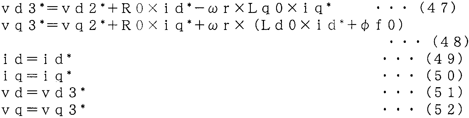
(43)~(52)식의 관계를 정리하면 (53), (54)식을 얻는다. Summarizing the relationship between equations (43) and (52), we obtain equations (53) and (54).

여기서는, 전류 지령을 id*=iq*=0으로 부여한다. 또한, 후단의 도 11에 따른 동작 설명에서 언급되지만, 구체적으로는, 교류 회전기(1b)를 어떤 방법으로 회전시킨 후에, id*=iq*=0으로 설정하여, 회전자 자속의 진폭과 위상을 측정하게 된다. Here, the current command is given by id * = iq * = 0. Further, although mentioned in the description of the operation according to FIG. 11 at a later stage, specifically, after rotating the alternating
이 경우, (53), (54)식은 (55), (56)식으로 된다. In this case, the formulas (53) and (54) are represented by the formulas (55) and (56).
![]()
![]()
이 (55), (56)식에 의하면, 위상차 Δθ 및 자속 오차 (φf0-φf)가 없는 경우, vd2* 및 vq2*은 0이며, 위상차 Δθ 또는 자속 오차 (φf0-φf)가 발생하는 경우, vd2* 또는 vq2* 중 적어도 한쪽은 0이 아니다. According to the equations (55) and (56), when there is no phase difference Δθ and magnetic flux error (φf0-φf), vd2 * and vq2 * are 0, and when phase difference Δθ or magnetic flux error (φf0-φf) occurs, At least one of vd2 * or vq2 * is not zero.
sinΔθ≒Δθ, cosΔθ≒1로 하여, (55), (56)식을 정리하면 (57), (58)식을 얻는다. By setting sinΔθ ≒ Δθ and cosΔθ ≒ 1, equations (55) and (56) are obtained (57) and (58).
![]()
![]()
(57)식으로부터 위상차 Δθ에 대해서 이하의 것을 알 수 있다. Equation (57) shows the following about the phase difference Δθ.
ㆍ (회전 직교 좌표의 d축 위상)>(회전자 자속의 위상)의 경우, vd2*<0Vd2 * <0 for (d-axis phase of rotational coordinates)> (phase of rotor magnetic flux)
ㆍ (회전 직교 좌표의 d축 위상)<(회전자 자속의 위상)의 경우, vd2*>0Vd2 * > 0 for (d-axis phase of rotational coordinates) <(phase of rotor magnetic flux)
따라서, vd2*가 플러스인 경우, 회전 직교 좌표의 d축 위상을 크게 하면 위상차 Δθ는 0에 가깝고, vd2*가 마이너스인 경우, 회전 직교 좌표의 d축 위상을 작게 하면 위상차 Δθ는 0에 가깝다. Therefore, when vd2 * is positive, when the d-axis phase of the rotational coordinate is increased, the phase difference Δθ is close to zero. When vd2 * is negative, when the d-axis phase of the rotational coordinate is reduced, the phase difference Δθ is close to zero.
마찬가지로, 상기 (58)식으로부터 회전자 자속의 진폭에 대해서 이하의 것을 알 수 있다. Similarly, from the above equation (58), the following can be seen about the amplitude of the rotor magnetic flux.
ㆍ (φf0)>(φf)의 경우, vq2*<0For (φf0)> (φf), vq2 * <0
ㆍ (φf0)<(φf)의 경우, vq2*>0Vq2 * > 0 for (φf0) <(φf)
따라서, vq2*가 플러스인 경우, φf0를 크게 하면 자속 진폭 오차 (φf0-φf)는 0에 가깝고, vq2*가 마이너스인 경우, φf0를 작게 하면 자속 진폭 오차 (φf0-φf)는 0에 가깝다. Therefore, when vq2 * is positive, increasing the phi f0 causes the magnetic flux amplitude error φf0-φf to be close to zero, and when vq2 * is negative, decreasing φf0 makes the magnetic flux amplitude error φf0-φf near to zero.
이상의 관계를 이용하여 정수 측정 수단(8d)은 (59), (60)식에 의해 제 2 전압 지령 vd2* 및 vq2*에 근거하여 연산한 위상차 Δθ를 회전 위치 검출기(4)가 출력하는 회전 위치 θ에 가산하고, 또한, 자속 진폭 설정값 φf0를 제 1 전압 지령 연산 수단(7b)에 출력한다. Using the above relationship, the constant measuring means 8d uses the (59) and (60) equations to determine the rotation position at which the
![]()
![]()
단, kθ, kφ: 비례 정수Where k θ and k φ are proportional constants
이상과 같이, 본 실시예 5에서는, 정수 측정 수단(8d)이 회전 2축 좌표(d-q축) 상의 전류 지령의 d축 성분 및 q축 성분을 일정값으로 유지하고, 제 2 전압 지령 연산 수단(9)이 출력하는 제 2 전압 지령에 근거하여 교류 회전기(1b)의 전기적 정수를 연산하기 때문에, 위상차 Δθ 및 자속 진폭 설정값 φf0라고 한 2종류의 전기적 정수를 측정할 수 있다고 하는 효과가 있다. As described above, in the fifth embodiment, the constant measuring means 8d maintains the d-axis component and the q-axis component of the current command on the rotational two-axis coordinate (dq axis) at a constant value, and the second voltage command calculation means ( Since the electrical constant of the
본 실시예 5에 있어서의 동작 파형의 일례를 도 11에 나타낸다. 도면에서, 1단째는 전류 지령의 d축 성분 id*, 2단째는 전류 지령의 q축 성분 iq*, 3단째는 교류 회전기(1b)의 각주파수 ωr, 4단째는 위상차 Δθ, 5단째는 자속 진폭 오차 (φf0-φf)를 나타내고 있다. An example of the operation waveform in Example 5 is shown in FIG. In the figure, the first stage is the d-axis component id * of the current command, the second stage is the q-axis component iq * of the current command, the third stage is the angular frequency ωr of the
시각 0~1초의 기간은 정지한 상태에서 전류 지령 id* 및 iq*은 0이다. 시각 1초 이후, id*는 0을 유지하는 동시에 iq*는 플러스의 일정값을 유지하고, 교류 회전기(1b)의 각주파수 ωr은 발생한 토크에 의해서 가속되어 간다. 정수 측정 수단(8d)은 시각 6초에 도달할 때까지는 동작을 정지해 놓는다. 시각 6초에 도달하면, id* 및 iq*는 0을 유지하고, 정수 측정 수단(8)은 제 2 전압 지령 vd2* 및 vq2*에 근거하여 위상차 Δθ 및 자속 진폭 설정값 φf0를 연산함으로써, 위상차 Δθ 및 자속 진폭 오차 (φf0-φf)는 0으로 수속한다. In the period of
id*=iq*=0의 조건을 만족시켜 놓으면, R이나 L에 기인하는 전압 강하가 발생하지 않기 때문에, R이나 L이 미지이더라도 φf0나 Δθ를 얻는 것이 가능해진다. If the condition of id * = iq * = 0 is satisfied, voltage drop due to R or L does not occur, so that phi f0 or Δθ can be obtained even if R or L is unknown.
이상과 같이, 본 실시예 5에서는, 정수 측정 수단(8d)이, 회전 2축 좌표(d-q축) 상의 전류 지령을 0으로 유지하고, 제 2 전압 지령 연산 수단(9)이 출력하는 제 2 전압 지령에 근거하여 교류 회전기(1b)의 전기적 정수를 연산하기 때문에, 위상차 Δθ 및 자속 진폭 설정값 φf0라고 한 2종류의 전기적 정수를 측정할 수 있다고 하는 효과가 있다. As described above, in the fifth embodiment, the constant measuring means 8d maintains the current command on the rotational two-axis coordinate (dq axis) at 0, and the second voltage outputted by the second voltage command calculating means 9 is output. Since the electrical constant of the
(실시예 6)(Example 6)
앞서의 각 실시예에 있어서의 교류 회전기는 동기기를 다루었다. 본 실시예 6에 있어서는, 교류 회전기(1e)가 유도기인 경우에 대해서 설명한다. The alternating current rotor in each of the above embodiments dealt with a synchronizer. In the sixth embodiment, the case where the
도 12는 본 발명의 실시예 6에 따른 구성을 나타내는 블럭도이며, 교류 회전기(1e)는 유도기이다. 또한, 도 12에서, 앞서의 실시예와 동일한 부호를 부여한 것은 동일 또는 이에 상당하는 것이며, 중복되는 부분의 각각의 설명은 생략한다. 12 is a block diagram showing the configuration according to the sixth embodiment of the present invention, wherein the alternating
제 1 전압 지령 연산 수단(7e)은 회전 2축 좌표(d-q축) 상의 전류 지령 id* 및 iq*과 각주파수 ω에 근거하여 회전 2축 좌표(d-q축) 상의 제 1 전압 지령 vd1* 및 vq1*을 출력하고, 또한, 슬립 각주파수 ωs를 출력한다. The first voltage command calculation means 7e performs the first voltage command vd1 * and vq1 on the rotation biaxial coordinate (dq axis) based on the current commands id * and iq * on the rotation biaxial coordinate (dq axis) and the angular frequency ω. * outputs, and further, it outputs the slip angular frequency ωs.
정수 측정 수단(8e)은 교류 회전기(1e)의 전기자 인덕턴스 설정값 Ls0 및 교류 회전기(1e)의 회전자 저항 설정값 Rr0을 연산하여, 제 1 전압 지령 연산 수단(7e)에 Ls0 및 Rr0을 출력한다. The constant measuring means 8e calculates the armature inductance set value Ls0 of the
속도 검출기(50)는 교류 회전기(1e)의 회전 각주파수 ωr을 검출하고, 가산기(51)는 회전 각주파수 ωr와 슬립 각주파수 ωs를 가산하여, 각주파수 ω를 출력한다. 적분기(52)는 가산기(51)로부터 얻은 각주파수 ω를 적분하여 위상 θ을 출력한다. The
교류 회전기(1e)는 유도기이며, 회전 직교 좌표(d-q축)가 임의의 각주파수 ω로 회전하고 있는 경우, 다음식이 성립한다. The alternating

단, only,
Rs: 교류 회전기(1e)의 전기자 저항Rs: armature resistance of alternating
Rr: 교류 회전기(1e)의 회전자 저항 Rr: rotor resistance of the alternating
Ls: 교류 회전기(1e)의 전기자 인덕턴스 Ls: armature inductance of alternating current rotor (1e)
M: 교류 회전기(1e)의 상호 인덕턴스 M: mutual inductance of the alternating
Lr: 교류 회전기(1e)의 회전자 인덕턴스Lr: rotor inductance of the alternating
σ: 교류 회전기(1e)의 누설 계수σ: leakage coefficient of the alternating
φdr: 교류 회전기(1e)의 회전자 자속의 d축 성분φdr: d-axis component of the rotor flux of the alternating
φqr: 교류 회전기(1e)의 회전자 자속의 q축 성분φqr: q-axis component of the rotor flux of the alternating
ωs: 교류 회전기(1e)의 슬립 각주파수ωs: Slip angular frequency of the alternating
한편, 제 1 전압 지령 연산 수단(7e)에서는, 회전 2축 좌표(d-q축) 상의 전류 지령 id* 및 iq*과 각주파수 ω에 근거하여 (65), (66)식에 의해서 회전 2축 좌표(d-q축) 상의 제 1 전압 지령 vd1* 및 vq1*을 출력하고, 또한, (67)식에 의해서 슬립 각주파수 ωs를 출력한다. On the other hand, in the first voltage command calculation means 7e, the rotational two-axis coordinates are expressed by the equations (65) and (66) based on the current commands id * and iq * on the rotational two-axis coordinates (dq axis) and the angular frequency ω. The first voltage commands vd1 * and vq1 * on the (dq axis) are output, and the slip angular frequency ωs is output by the equation (67).
![]()
![]()
단, only,
Rs0: 교류 회전기(1e)의 전기자 저항 설정값 Rs0: Armature resistance setting value of the
Rr0: 교류 회전기(1e)의 회전자 저항 설정값Rr0: Rotor resistance setting value of the
Ls0: 교류 회전기(1e)의 전기자 인덕턴스 설정값Ls0: Armature inductance set value of
Lr0: 교류 회전기(1e)의 회전자 인덕턴스 설정값Lr0: Rotor inductance setting value of the
σ0: 교류 회전기(1e)의 누설 계수 설정값sigma 0: Leakage coefficient setting value of the
여기서는, 교류 회전기(1e)의 누설 계수는 기지이고 또한 전기자 인덕턴스와 회전자 인덕턴스가 동등하며, 즉, σ0=σ 및 Ls0=Lr0, Ls=Lr이 성립하고 있는 경우에 대해서 설명한다. Here, the case where the leakage coefficient of the
앞서의 실시예 1의 경우와 마찬가지로, 동작이 정상 상태이고, 제 2 전압 지령 연산 수단(9)의 출력인 제 2 전압 지령 연산값 vd2* 및 vq2*의 절대값이 0에 가까운 소정의 범위 내로 된 시점에서는 이하의 동작을 확인할 수 있다. As in the case of the first embodiment, the operation is in a normal state, and the absolute values of the second voltage command arithmetic values vd2 * and vq2 * , which are outputs of the second voltage command calculating means 9, are within a predetermined range close to zero. At this point, the following operations can be confirmed.
즉, 제 2 전압 지령 연산 수단(9)에서는, 전류 지령의 d축 성분 id*과 전류의 d축 성분 id가 일치하고, 또한, 전류 지령의 q축 성분 iq*과 전류의 q축 성분 iq가 일치하고 있다. 또한, 전압 인가 수단(2)은, 제 3 전압 지령 연산 수단(10)이 출력하는 제 3 전압 지령 vd3* 및 vq3*에 근거하여 교류 회전기(1e)에 전압을 인가하고 있기 때문에, 교류 회전기(1e)의 전압의 d축 성분 vd 및 q축 성분 vq은 제 3 전압 지령 vd3* 및 vq3*에 일치한다. 이것들의 관계를 감안하면 (68)~(73)식이 성립한다. That is, in the second voltage command calculation means 9, the d-axis component id * of the current command and the d-axis component id of the current coincide, and the q-axis component iq * of the current command and the q-axis component iq of the current Is in agreement. In addition, since the

여기서, 전기자 저항 및 회전자 저항에 대해서 Rs0=Rs, Rr0=Rr이 성립하는 경우, (65)~(73)식에 대입하여 vd2*, vq2*에 관한 근사해를 구하면 (74), (75)식을 얻는다. Here, when Rs0 = Rs and Rr0 = Rr for the armature resistance and the rotor resistance, the approximate solutions for vd2 * and vq2 * are obtained by substituting equations (65) to (73) (74), (75) Get an expression.

이 (74), (75)식에 의하면, 전기자 인덕턴스 오차 (Ls0-Ls)가 없는 경우, vd2* 및 vq2*은 0이며, 전기자 인덕턴스 오차가 발생하는 경우, vd2* 및 vq2*은 0이 아니게 된다. According to the 74, 75, expression, when there is no armature inductance tolerance (Ls0-Ls), vd2 * and vq2 * is 0, if the armature inductance error occurs, vd2 * and vq2 * is no longer zero do.
한편, 전기자 저항 및 전기자 인덕턴스에 대해서 Rs0=Rs, Ls0=Ls가 성립하는 경우, (65)~(73)식에 대입하여 vd2*, vq2*에 관한 근사해를 구하면 (76), (77)식을 얻는다. On the other hand, when Rs0 = Rs and Ls0 = Ls hold for the armature resistance and the armature inductance, the equations (76) and (77) are obtained by substituting equations (65) to (73) for equations (vd2 * , vq2 * ). Get

상기 (74)~(77)식을 감안하면, 전기자 저항이 기지이며, 회전자 저항 및 전기자 인덕턴스가 미지인 경우, vd2*, vq2*에 관해서 (78), (79)의 근사식이 성립한다. In view of the above formulas (74) to (77), when the armature resistance is known and the rotor resistance and the armature inductance are unknown, the approximation equations of (78) and (79) are satisfied with respect to vd2 * and vq2 * .

Ls0=Lr0로 하여 (78), (79)식을 정리하면 (80), (81)식을 얻는다.If Ls0 = Lr0, the equations (78) and (79) are summarized to obtain the equations (80) and (81).

그리고, 본 실시예 6에서는, id*과 iq*를 플러스의 일정값 I1*로 부여하여, ω>0인 경우에 대해서 생각한다. 이때, (80), (81)식은 (82), (83)식으로 된다. In the sixth embodiment, id * and iq * are given as positive constant values I1 * , and the case where ω> 0 is considered. At this time, the formulas (80) and (81) become (82) and (83) formulas.

(82)식으로부터 전기자 인덕턴스에 대해서 이하의 것을 알 수 있다. From the equation (82), the following can be seen about the armature inductance.
ㆍ (Ls0)>(Ls)의 경우, (vd2*+vq2*)<0For (Ls0)> (Ls), (vd2 * + vq2 * ) <0
ㆍ (Ls0)<(Ls)의 경우, (vd2*+vq2*)>0(Vd2 * + vq2 * )> 0 for (Ls0) <(Ls)
따라서, (vd2*+vq2*)가 플러스인 경우, 전기자 인덕턴스 설정값 Ls0을 크게 하면 전기자 인덕턴스 오차 (Ls0-Ls)는 0에 가깝고, (vd2*+vq2*)가 마이너스인 경우, 전기자 인덕턴스 설정값 Ls0을 작게 하면 전기자 인덕턴스 오차 (Ls0-Ls)는 0에 가깝다. Therefore, if (vd2 * + vq2 * ) is positive, increasing the armature inductance set value Ls0 causes the armature inductance error (Ls0-Ls) to be close to zero, and if (vd2 * + vq2 * ) is negative, the armature inductance setting is If the value Ls0 is made small, the armature inductance error (Ls0-Ls) is close to zero.
마찬가지로, 상기 (83)식으로부터 회전자 저항에 대해서 이하의 것을 알 수 있다. Similarly, from the above equation (83), the following can be seen for the rotor resistance.
ㆍ (Rr0)>(Rr)의 경우, (vd2*-vq2*)>0When (Rr0)> (Rr), (vd2 * -vq2 * )> 0
ㆍ (Rr0)<(Rr)의 경우, (vd2*-vq2*)<0(Vd2 * -vq2 * ) <0 for (Rr0) <(Rr)
따라서, (vd2*-vq2*)가 플러스인 경우, Rr0를 작게 하면 회전자 저항 오차 (Rr0-Rr)는 0에 가깝고, (vd2*-vq2*)가 마이너스인 경우, Rr0를 크게 하면 회전자 저항 오차 (Rr0-Rr)는 0에 가깝다. Therefore, if (vd2 * -vq2 * ) is positive, if Rr0 is made small, the rotor resistance error (Rr0-Rr) is close to 0. If (vd2 * -vq2 * ) is negative, if Rvd is made large, the rotor is made larger. Resistance error (Rr0-Rr) is close to zero.
이상의 관계를 이용하여 정수 측정 수단(8e)은, (84), (85)식에 의해 제 2 전압 지령 vd2* 및 vq2*에 근거하여 연산한 교류 회전기(1e)의 전기자 인덕턴스 설정값 Ls0 및 회전자 저항 설정값 Rr0을 제 1 전압 지령 연산 수단(7e)에 출력한다. Using the above relationship, the constant measuring means 8e calculates the armature inductance set value Ls0 and the times of the alternating
![]()
![]()
단, kLs, kRr: 비례 정수Where k Ls and k Rr are proportional integers
본 실시예 6에 있어서의 동작 파형의 일례를 도 13에 나타낸다. 도면에서, 1단째는 전류 지령의 d축 성분 id*, 2단째는 전류 지령의 q축 성분 iq*, 3단째는 교류 회전기(1e)의 회전 각주파수 ωr, 4단째는 회전자 저항 오차 (Rr0-Rr), 5단째는 전기자 인덕턴스 오차 (Ls0-Ls)를 나타내고 있다. An example of the operation waveform in Example 6 is shown in FIG. In the figure, the first stage is the d-axis component id * of the current command, the second stage is the q-axis component iq * of the current command, the third stage is the rotational angular frequency ωr of the
시각 0~1초의 기간은, 정지한 상태에서 id*는 I1*, iq*는 0이다. 시각 1초 이후, id*와 iq*의 크기는 I1*를 유지하고, 교류 회전기(1e)의 회전 각주파수 ωr는 발생한 토크에 의해서 가속되어 간다. In the period of
정수 측정 수단(8e)은 시각 3초에 도달할 때까지는 동작을 정지하고 있고, 시각 3초에 도달하면, 제 2 전압 지령 vd2* 및 vq2*에 근거하여 전기자 인덕턴스 설정값 Ls0을 연산함으로써, Ls0는 전기자 인덕턴스 Ls에 가깝고 인덕턴스 오차 (Ls0-Ls)는 0으로 수속한다. The constant measuring means 8e stops operation until the
회전자 저항에 대해서도, 정수 측정 수단(8e)은 시각 3초에 도달하면, 제 2 전압 지령 vd2* 및 vq2*에 근거하여 회전자 저항 설정값 Rr0을 연산함으로써, Rr0는 회전자 저항 Rr에 가깝고 회전자 저항 오차 (Rr0-Rr)는 0으로 수속한다. Also for the rotor resistance, the constant measuring means 8e calculates the rotor resistance set value Rr0 based on the second voltage commands vd2 * and vq2 * when time constant 3 seconds, whereby Rr0 is close to the rotor resistance Rr. The rotor resistance error (Rr0-Rr) converges to zero.
또한, (84), (85)식은 회전자 저항이나 전기자 인덕턴스의 설정값을 제 2 전압 지령을 적분해서 얻도록 했기 때문에, 전압 검출값이나 전류 검출값의 노이즈가 직접 반영되는 것을 방지하여, 측정한 정수도 노이즈의 영향을 받는 문제를 해결할 수 있다. In addition, since formulas (84) and (85) are obtained by integrating the second voltage command with the set value of the rotor resistance and the armature inductance, the noise of the voltage detection value or the current detection value is directly reflected and measured. One integer solves the problem of noise.
또한, 본 실시예 6에 나타낸 정수 측정 수단(8e)은 전기자 인덕턴스 설정값 Ls0의 연산을 행했지만, 유도기인 교류 회전기(1e)에는 Ls≒Lr≒M의 관계가 있기 때문에, 정수 측정 수단(8e)은 Ls0 대신에 회전자 인덕턴스 또는 상호 인덕턴스의 설정값을 연산해도 좋다. The constant measuring means 8e shown in the sixth embodiment performed the armature inductance set value Ls0. However, since the alternating
이상과 같이, 본 실시예 6에서는, 교류 회전기(1e)는 유도기이며, 제 1 전압 지령 연산 수단(7e)은, 정수 측정 수단(8e)이 출력하는 전기적 정수를 이용하여 교류 회전기(1e)의 슬립 각주파수 ωs를 연산하고, 또한, 이 슬립 각주파수 ωs와 교류 회전기(1e)의 회전 각주파수 ωr와의 합을 임의의 각주파수 ω로서 출력하는 가산기(51)를 구비했기 때문에, 교류 회전기(1e)가 슬립이 발생하는 유도기이더라도, 상기 교류 회전기(1e)의 전기적 정수를 얻을 수 있다고 하는 효과가 있다. As described above, in the sixth embodiment, the
또한, 교류 회전기(1e)는 유도기이며, 정수 측정 수단(8e)은 상호 인덕턴스값, 전기자 인덕턴스값, 회전자 저항값을 제 2 전압 지령에 근거해서 연산하여 제 1 전압 지령 연산 수단(7e)에 출력하기 때문에, 유도기의, 전기자 인덕턴스값과 회전자 저항값을 정수 측정 수단(8e)이 측정하여, 제 1 전압 지령 연산 수단(7e)에서 이용하는 전기적 정수로서 설정할 수 있다. The alternating
또한, 정수 측정 수단(8e)은 제 2 전압 지령 연산 수단(9)이 출력하는 제 2 전압 지령의 d축 성분과 q축 성분의 합에 근거하여, 전기자 인덕턴스값을 연산하고, 그 연산 결과를 제 1 전압 지령 연산 수단(7e)에 출력하기 때문에, 유도기인 교류 회전기(1e)의 전기자 인덕턴스값을 보다 정확하게 측정하여, 제 1 전압 지령 연산 수단(7e)에서 이용하는 전기적 정수를 설정할 수 있다고 하는 효과가 있다. The constant measuring means 8e calculates the armature inductance value based on the sum of the d-axis component and the q-axis component of the second voltage command outputted by the second voltage command calculating means 9, and calculates the result of the calculation. Since it outputs to the 1st voltage command calculating means 7e, the effect that an electric constant used by the 1st voltage command calculating means 7e can be set by measuring the armature inductance value of the
또한, 정수 측정 수단(8e)은 제 2 전압 지령 연산 수단(9)이 출력하는 제 2 전압 지령의 d축 성분과 q축 성분의 차에 근거하여 회전자 저항값을 연산하고, 그 연산 결과를 제 1 전압 지령 연산 수단(7e)에 출력하기 때문에, 유도기인 교류 회전기(1e)의 회전자 저항을 정확하게 측정하여, 제 1 전압 지령 연산 수단(7e)에서 이용하는 전기적 정수를 설정할 수 있다고 하는 효과가 있다. Further, the constant measuring means 8e calculates the rotor resistance value based on the difference between the d-axis component and the q-axis component of the second voltage command calculated by the second voltage command calculating means 9, and calculates the result of the calculation. Since it outputs to the 1st voltage command calculating means 7e, the effect that an electric constant used by the 1st voltage command calculating means 7e can be set by measuring the rotor resistance of the
이상과 같이, 본 실시예 6에서는, 정수 측정 수단(8e)이 회전 2축 좌표(d-q축) 상의 전류 지령의 d축 성분과 q축 성분을 소정값 I1*으로 유지하고, 제 2 전압 지령 연산 수단(9)이 출력하는 제 2 전압 지령에 근거하여 교류 회전기(1e)의 전기 적 정수를 연산하기 때문에, 유도기의 전기자 인덕턴스 및 회전자 저항이라고 한 2종류의 전기적 정수를 측정할 수 있다고 하는 효과가 있다. 즉, 정수 측정 수단(8e)은, 회전 2축 좌표(d-q축) 상의 전류 지령의 d축 성분의 크기와 q축 성분의 크기가 동등할 때의 제 2 전압 지령 연산 수단(9)이 출력하는 제 2 전압 지령에 근거하여 교류 회전기(1e)의 전기적 정수를 연산하기 때문에, 전기자 인덕턴스와 회전자 저항이라고 한 교류 회전기의 전기적 정수를 측정하여, 제 1 전압 지령 연산 수단(7e)에서 이용하는 전기적 정수를 설정할 수 있다고 하는 효과가 있다. As described above, in the sixth embodiment, the constant measuring means 8e maintains the d-axis component and the q-axis component of the current command on the rotational two-axis coordinate (dq axis) at a predetermined value I1 * , and the second voltage command calculation is performed. Since the electrical constant of the alternating
(실시예 7)(Example 7)
앞서의 실시예 6에서는, 정수 측정 수단(8e)은 (84), (85)식에 따라, 제 2 전압 지령 vd2* 및 vq2*에 근거하여 교류 회전기(1e)의 전기자 인덕턴스 설정값 Ls0과 회전자 저항 설정값 Rr0을 연산하고 있었지만, 제 2 전압 지령 vd2*, vq2*, 전류 지령 id*, iq* 및 각주파수 ω에 근거하여 전기자 인덕턴스 설정값 Ls0와 회전자 저항 설정값 Rr0를 연산해도 좋다. In the sixth embodiment, the constant measuring means 8e times the armature inductance set value Ls0 of the alternating
도 14는 본 발명의 실시예 7에 따른 구성을 나타내는 블럭도이며, 정수 측정 수단(8f)은 전기자 인덕턴스 설정값 Ls0과 회전자 저항 설정값 Rr0을 제 2 전압 지령 vd2*, vq2*, 전류 지령 id*, iq* 및 각주파수 ω에 근거하여 연산하고, 제 1 전압 지령 연산 수단(7e)에 Ls0 및 Rr0를 출력한다. 또한, 도 14에서, 도 1과 동일한 부호를 부여한 것은 동일 또는 이에 상당하는 것이며, 중복되는 부분의 각각의 설명은 생략한다. Fig. 14 is a block diagram showing the construction according to the seventh embodiment of the present invention, wherein the constant measuring means 8f uses the armature inductance set value Ls0 and the rotor resistance set value Rr0 as the second voltage command vd2 * , vq2 * , current command. It calculates based on id * , iq *, and angular frequency (omega), and outputs Ls0 and Rr0 to the 1st voltage command calculating means 7e. In addition, in FIG. 14, the same code | symbol as FIG. 1 is the same or it corresponds, and each description of the overlapping part is abbreviate | omitted.
(80), (81)식을 (86), (87)식으로서 재게한다. The equations (80) and (81) are rewritten as equations (86) and (87).

이 (86)식의 우변은, -(vd2*×iq*+vq2*×id*)의 크기에 비례하고, id*2의 크기에 반비례하고, 또한, ω의 크기에 반비례한다. The right side of the 86 expression is-proportional to the magnitude of (vd2 + vq2 * iq * × × * id *), and inversely proportional to the magnitude of id * 2, and further inversely proportional to the size of ω.
또한, (87)식의 우변은, (vd2*×iq*-vq2*×id*)의 크기에 비례하고, (id*×iq*)의 크기에 반비례하고, 또한, ω의 크기에 반비례한다. In addition, the right side of the equation (87) is proportional to the size of (vd2 * × iq * −vq2 * × id * ), inversely proportional to the size of (id * × iq * ), and inversely proportional to the magnitude of ω. .
이를 감안하여, 본 실시예 7에 나타내는 정수 측정 수단(8f)은 (88), (89)식에 근거하여 교류 회전기(1e)의 전기자 인덕턴스 설정값 Ls0와 회전자 저항 설정값 Rr0를 제 1 전압 지령 연산 수단(7e)에 출력한다. In view of this, the constant measuring means 8f shown in the seventh embodiment uses the armature inductance set value Ls0 and the rotor resistance set value Rr0 of the alternating

단, kLs, kRr: 비례 정수Where k Ls and k Rr are proportional integers
앞서의 실시예 6에서는, id*과 iq*는 플러스의 일정값이고, 또한 각주파수 ω도 플러스라고 하는 제약이 수반되었다. 본 실시예 7에서는, 정수 측정 수단(8f)이 (88), (89)식을 이용하기 때문에, iq*의 부호나 크기, 및 ω의 부호나 크 기에 관계없이, 정확한 전기자 인덕턴스 설정값 Ls0과 회전자 저항 설정값 Rr0을 연산할 수 있다. In the sixth embodiment, id * and iq * are constant values of plus, and the angular frequency ω is also positive. In the seventh embodiment, since the constant measuring means 8f uses the equations (88) and (89), regardless of the sign and magnitude of iq * and the sign or magnitude of ω, the exact armature inductance set value Ls0 and Rotor resistance setting value Rr0 can be calculated.
도 15는 본 실시예 7에 있어서의 정수 측정 수단(8f)의 내부 구성을 나타내는 도면이다. 도면에서, 승산기(60)는 제 2 전압 지령의 d축 성분 vd2*와 전류 지령의 q축 성분 iq*와의 곱을 연산하고, 승산기(61)는 제 2 전압 지령의 q축 성분 vq2*와 전류 지령의 d축 성분 id*와의 곱을 연산한다. 가산기(62)는 승산기(60)의 출력과 승산기(61)의 출력을 가산한다. 승산기(63)는 전류 지령의 d축 성분 id*의 자승과 각주파수 ω의 곱을 연산하여 리미터(64)에 출력한다. 리미터(64)는 승산기(63)의 출력이 플러스인 경우에는 플러스의 소정값 이상으로 되도록 리미트 동작을 행하고, 또한, 승산기(63)의 출력이 마이너스인 경우에는 마이너스의 소정값 이하로 되도록 리미트 동작을 행함으로써, 제산기(65)가 0으로 제산하지 않도록 한다. 제산기(65)는 가산기(62)의 출력을 리미터(64)의 출력으로 제산하고, 적분기(66)는 제산기(65)의 값을 적분하여 kLs배 하여, 전기자 인덕턴스 설정값 Ls0로서 출력한다. 승산기(60), 승산기(61), 가산기(62), 승산기(63), 리미터(64), 제산기(65), 적분기(66)에 의한 일련의 연산에 의해서 (88)식을 연산할 수 있다. Fig. 15 is a diagram showing the internal configuration of the constant measuring means 8f in the seventh embodiment. In the figure, the
마찬가지로, 승산기(67)는 제 2 전압 지령의 d축 성분 vd2*과 전류 지령의 d축 성분 id*와의 곱을 연산하고, 승산기(68)는 제 2 전압 지령의 q축 성분 vq2*과 전류 지령의 q축 성분 iq*와의 곱을 연산한다. 감산기(69)는 승산기(67)의 출력으로부터 승산기(68)의 출력을 감산한다. 승산기(70)는 전류 지령 id*과 iq*와 각주파수 ω와의 곱을 연산하여 리미터(71)에 출력한다. 리미터(71)는 승산기(70)의 출력이 플러스인 경우에는 플러스의 소정값 이상으로 되도록 리미트 동작을 행하고, 또한, 승산기(70)의 출력이 마이너스인 경우에는 마이너스의 소정값 이하로 되도록 리미트 동작을 행함으로써, 제산기(72)가 영으로 제산하지 않도록 한다. 제산기(72)는 감산기(69)의 출력을 리미터(71)의 출력으로 제산하고, 적분기(73)는 제산기(72)의 값을 적분하여 -kRr배 하여, 회전자 저항 설정값 Rr0로서 출력한다. 승산기(67), 승산기(68), 감산기(69), 승산기(70), 리미터(71), 제산기(72), 적분기(73)에 의한 일련의 연산에 의해서 (89)식을 연산할 수 있다. Similarly, the
이상과 같이, 본 실시예 7에서는, 정수 측정 수단(8f)은 제 2 전압 지령 vd2*, vq2*, 전류 지령의 id*, iq* 및 각주파수 ω에 근거하여 회전자 저항 설정값 Rr0과 전기자 인덕턴스 설정값 Ls0을 연산하도록 했기 때문에, 전류 지령 id*, iq* 및 각주파수 ω의 부호나 크기에 관계없이, 정확한 회전자 저항 설정값 및 전기자 인덕턴스 설정값을 얻는 효과가 있다. As described above, in the seventh embodiment, the constant measuring means 8f uses the rotor resistance set value Rr0 and the armature based on the second voltage command vd2 * , vq2 * , the id * , iq * and the angular frequency ω of the current command. Since the inductance set value Ls0 is calculated, an accurate rotor resistance set value and an armature inductance set value can be obtained regardless of the sign or magnitude of the current command id * , iq * and the angular frequency ω.
(실시예 8)(Example 8)
앞서의 실시예 7에서는, 전류 지령의 d축 성분 id*을 소정값으로 부여하고 있었지만, 각주파수 ω가 기준 각주파수 ωBASE(전압 포화가 발생하지 않는 최대 각주파수)일 때 전압 인가 수단(2)이 출력 가능한 최대 전압 진폭으로 되도록 id*을 조정해도 좋다. In the seventh embodiment described above, the d-axis component id * of the current command is given to a predetermined value, but the
교류 회전기(1e)의 전압 진폭을 크게 할 수 있으면, 동일한 출력에 대하여 전류 진폭을 작게 할 수 있어, 동손(銅損) 등의 손실 저감에 의한 고효율 제어가 가능하게 된다. 그러나, 전압 인가 수단(2)이 출력할 수 없는 전압 진폭으로 제어하고자 하면 전압 포화가 발생하여, 소망하는 제어 특성을 얻을 수 없다. 그래서, 전압 인가 수단(2)이 출력하는 각주파수가 기준 각주파수 ωBASE일 때에 출력 가능한 최대 전압 진폭으로 되도록 id*을 조정함으로써, 각주파수 ω가 기준 각주파수 ωBASE 이하에서는 전압 포화가 발생하지 않는 범위에서 전압 진폭이 크게 되도록 한다. If the voltage amplitude of the
이상의 관점에서, 이 실시예 8은 전기적 정수의 개념을 넓게 파악하여, 전류 지령의 d축 성분 id*을 전기적 정수로서 취급하고, 이 id*를 구하는 자속 조정 수단(80)을 새롭게 마련한 것이다. In view of the above, the eighth embodiment broadly grasps the concept of the electrical constant, treats the d-axis component id * of the current command as the electrical constant, and newly provides a magnetic flux adjusting means 80 for obtaining this id * .
도 16은 본 발명의 실시예 8에 따른 구성을 나타내는 블럭도이며, 자속 조정 수단(80)은 전압 인가 수단(2)에 입력되는 제 3 전압 지령 vd3*, vq3* 및 각주파수 ω에 근거하여 전류 지령의 d축 성분 id*을 출력한다. 공지한 바와 같이, 교류 회 전기(1e)의 자속 진폭은 전류 지령의 d축 성분 id*에 비례하기 때문에, id*를 조정하는 것은 교류 회전기(1e)의 자속을 조정하는 것이기도 하다. 또한, 도 16에서 도 14와 동일한 부호를 부여한 것은 동일 또는 이에 상당하는 것이며, 중복 부분의 각각의 설명은 생략한다. Fig. 16 is a block diagram showing the arrangement according to the eighth embodiment of the present invention, wherein the magnetic flux adjusting means 80 is based on the third voltage command vd3 * , vq3 * and the angular frequency ω input to the
자속 조정 수단(80)의 동작을 설명하기 전에, 교류 회전기(1e)의 전압 진폭, 즉, 전압 인가 수단(2)에 입력되는 제 3 전압 지령의 진폭과, 전류 지령의 d축 성분 id*과의 관계에 대해서 설명한다. Before explaining the operation of the magnetic flux adjusting means 80, the voltage amplitude of the
도 17은 각주파수 50÷2π[rad/s] 및 60÷2π[rad/s]에 있어서 전류 지령 id*와 전압 지령의 진폭과의 관계를 나타내는 도면이며, 전압 지령의 진폭은 (90)식으로 정의된다. Fig. 17 is a graph showing the relationship between the current command id * and the voltage command amplitude at the
![]()
![]()
도 17을 보고서 알 수 있는 바와 같이, 전류 지령의 d축 성분 id*를 100%보다 크게 하면 전압 지령의 진폭은 커지는 동시에, id*를 20%보다 크게 하더라도 전압 지령의 진폭은 커지기 때문에, id*와 전압 지령의 진폭은 비례 관계는 아니다. 그러나, id*가 100% 근방인 범위에 한정되면, 도 17의 근사 직선과 같이, id*와 전압 지령의 진폭이 비례하는 관계라고 간주해도 좋다. Since also like 17 can be seen Report, increasing the d-axis component of the current command id * than 100% of the amplitude of the voltage command is at the same time increases, the amplitude of the larger, even if the voltage command for id * than 20% larger, id * The amplitude of and the voltage command is not proportional. However, if id * is limited to the range which is 100% vicinity, you may consider that it is a relationship in which id * and the amplitude of a voltage command are proportionately like the approximated straight line of FIG.
도 18은 각주파수 ω와 전압 지령의 진폭과의 관계를 나타내는 도면이고, id*가 50~20%의 범위이면, 각주파수 ω와 전압 지령의 진폭과의 관계는 대략 비례 관계라고 말해도 좋다. 특히, 기준 각주파수 ωBASE를 60×2π[rad/s]로 설정하는 경우, 전류 지령의 d축 성분 id*가 50~200%, 또한, 각주파수 ω가 기준 각주파수 ωBASE 근방에서는, 각주파수 ω와 전압 지령의 진폭은 비례 관계에 있고, 또한, id*와 전압 지령의 진폭도 비례 관계에 있다고 말해도 좋다. 환언하면, 다음의 관계가 성립한다. Fig. 18 is a diagram showing the relationship between the angular frequency ω and the amplitude of the voltage command. If id * is in the range of 50 to 20%, the relationship between the angular frequency ω and the amplitude of the voltage command may be said to be approximately proportional. In particular, when the reference angular frequency ω BASE is set to 60 × 2π [rad / s], the d-axis component id * of the current command is 50 to 200%, and the angular frequency ω is near the reference angular frequency ω BASE. It may be said that the frequency ω and the amplitude of the voltage command are in proportional relationship, and that id * and the amplitude of the voltage command are in proportional relationship. In other words, the following relationship holds.
전압 지령의 진폭 ∝ ω×id* Amplitude of Voltage Reference ∝ ω × id *
단, 전류 지령의 d축 성분 id*는 100% 근방이고, 또한, 각주파수 ω는 ωBASE 근방이라고 한다. However, the d-axis component id * of the current command is around 100%, and the angular frequency ω is called ω BASE .
이상의 관계를 감안하여, 자속 조정 수단(80)은 전압 인가 수단(2)에 입력되는 제 3 전압 지령 vd3*, vq3* 및 각주파수 ω에 근거하여, 각주파수 ω가 기준 각주파수 ωBASE일 때에 전압 인가 수단(2)이 출력 가능한 최대 전압 진폭으로 되도록 id*을 조정한다. In view of the above relationship, the magnetic flux adjusting means 80 is based on the third voltage command vd3 * , vq3 * and the angular frequency ω input to the
도 19는 본 실시예에서의 자속 조정 수단(80)의 내부 구성을 나타내는 도면이다. 도면에서, 절대값 연산기(90)는 각주파수 ω의 절대값을 연산하고, 이득 연산기(91)는 절대값 연산기(90)의 출력을 1/ωBASE배 한다. 승산기(92)는 제 3 전압 지령의 d축 성분 vd3*의 자승을 연산하고, 승산기(93)는 제 3 전압 지령의 q축 성분 vq3*의 자승을 연산한다. 19 is a diagram showing the internal configuration of the magnetic flux adjusting means 80 in this embodiment. In the figure, the
가산기(94)는 승산기(92)의 출력과 승산기(93)의 출력을 가산 연산하고, 평방 연산기(95)는 가산기(94)의 평방을 연산하고, 이득 연산기(96)는 평방 연산기(95)의 출력을 1/VBASE배 한다. 여기서, VBASE는 전압 인가 수단(2)이 출력 가능한 최대 전압 진폭이다. The
감산기(97)는 이득 연산기(91)의 출력으로부터 이득 연산기(96)의 출력을 감산하고, 증폭기(98)는 감산기(97)의 출력을 적분 또는 비례 적분에 의해서 증폭한다. 이 비례 적분에 의해서 「절대값 연산기(90)의 출력의 1/ωBASE배」와 「평방 연산기(95)의 출력의 1/VBASE배」를 일치시키는 것이 가능하고, 그 결과, 각주파수 ω가 ωBASE일 때에 전압 지령의 진폭이 VBASE로 되는 전류 지령의 d축 성분 id*를 출력할 수 있다. 리미터(99)는 증폭기(98)의 출력이 id*의 50~200%로 되도록 상한과 하한을 리미트한다. The
정수 측정 수단으로서 기능하는 자속 조정 수단(80)을 도 19의 구성으로 함으로써, 각주파수 ω가 ωBASE일 때에 전압 지령의 진폭이 VBASE로 되는 전류 지령의 d축 성분 id*를 출력할 수 있다. By setting the magnetic flux adjusting means 80 functioning as the constant measuring means to have the configuration shown in Fig. 19, when the angular frequency ω is ω BASE , the d-axis component id * of the current command whose amplitude of the voltage command is V BASE can be output. .
본 실시예 8에서의 동작 파형의 일례를 도 20에 나타낸다. 도면에서, 1단째 는 전류 지령의 d축 성분 id*, 2단째는 전류 지령의 q축 성분 iq*, 3단째는 교류 회전기(1e)의 회전 각주파수 ωr, 4단째는 회전자 저항 오차 (Rr0-Rr), 5단째는 전기자 인덕턴스 오차 (Ls0-Ls)를 나타내고 있다. 20 shows an example of the operation waveform in the eighth embodiment. In the figure, the first stage is the d-axis component id * of the current command, the second stage is the q-axis component iq * of the current command, the third stage is the rotational angular frequency ωr of the
시각 0~1초의 기간은, 정지한 상태에서 id*는 I1*, iq*는 0이다. 시각 1초 이후, id*와 iq*의 크기는 I1*를 유지하고, 교류 회전기(1e)의 회전 각주파수 ωr는 발생한 토크에 의해서 가속되어 간다. 정수 측정 수단(8f)은 시각 3초에 도달할 때까지는 동작을 정지하고 있고, 시각 3초에 도달하면, 제 2 전압 지령 vd2* 및 vq2*에 근거하여 전기자 인덕턴스 설정값 Ls0을 연산함으로써, Ls0는 전기자 인덕턴스 Ls에 가깝고 전기자 인덕턴스 오차 (Ls0-Ls)는 0으로 수속한다. In the period of
회전자 저항에 대해서도, 정수 측정 수단(8f)은 시각 3초에 도달하면, 제 2 전압 지령 vd2* 및 vq2*에 근거하여 회전자 저항 설정값 Rr0을 연산함으로써, Rr0는 회전자 저항 Rr에 가깝고 회전자 저항 오차 (Rr0-Rr)는 0으로 수속한다. Also for the rotor resistance, the constant measuring means 8f calculates the rotor resistance set value Rr0 based on the second voltage commands vd2 * and vq2 * when the
자속 조정 수단(80)은 시각 8초에 도달할 때까지는 동작을 정지하고 있다. I1*으로 유지되고 있는 전류 지령의 d축 성분 id*은 100% 근방이며, 또한, 시각 8초에 도달한 시점에서 각주파수 ω는 ωBASE 근방으로 되기 때문에, 시각 8초부터 자속 조정 수단(80)은 동작을 개시하고, 각주파수 ω가 ωBASE일 때에 전압 인가 수단(2) 이 출력 가능한 최대 전압 진폭 VBASE로 되는 id*를 조정할 수 있다. The magnetic flux adjusting means 80 stops the operation until it reaches
이상과 같이, 본 실시예 8에서는, 자속 조정 수단(80)이 소정 속도 근방으로 전압 지령의 진폭의 정수배가 각주파수 ω의 정수배에 일치하도록 전류 지령의 d축 성분 id*을 조정함으로써, 교류 회전기(1e)의 자속을 조정하도록 했기 때문에, 전압 인가 수단(2)이 기준 각주파수 ωBASE일 때에 출력 가능한 최대 전압 진폭으로 되는 id*를 얻고, 각주파수 ω가 기준 각주파수 ωBASE 이하에서는 전압 포화가 발생하지 않는 범위에서 전압 진폭이 커지도록 할 수 있기 때문에, 교류 회전기(1e)를 안정하고 또한 효율적으로 제어할 수 있다고 하는 효과가 있다. As described above, in the eighth embodiment, the magnetic flux adjusting means 80 adjusts the d-axis component id * of the current command such that the integer multiple of the amplitude of the voltage command coincides with the integer multiple of the angular frequency ω near the predetermined speed. Since the magnetic flux of (1e) is adjusted, id * is obtained as the maximum voltage amplitude that can be output when the
또한, 본 발명의 각 변형예에 있어서, 정수 측정 수단은 정수 설정값을, 제 2 전압 지령 연산 수단으로부터의 제 2 전압 지령, 전류 지령 및 각주파수에 근거하여 연산하기 때문에, 정수 설정값을 연산하는 조건이 완화되어, 정수 설정값을 구하는 연산의 수속성이 향상한다. Moreover, in each modified example of this invention, since the integer measuring means calculates a constant setting value based on the 2nd voltage command, the current command, and the angular frequency from a 2nd voltage command calculating means, it calculates a constant setting value. The condition to be relaxed is improved, and the convergence of the operation for calculating the integer set value is improved.
또한, 교류 회전기는 동기기이며, 정수 측정 수단은 제 2 전압 지령의 q축 성분에 근거하여, 정수 설정값으로서의 전기자 저항 설정값을 연산하기 때문에, 교류 회전기인 동기기의 전기자 저항이 간편하고 정밀하게 구해진다. In addition, since the alternator is a synchronous machine and the constant measuring unit calculates the armature resistance set value as an integer set value based on the q-axis component of the second voltage command, the armature resistance of the synchronous machine which is the alternator is easily and precisely determined. Become.
교류 회전기는 동기기이며, 정수 측정 수단은 제 2 전압 지령의 d축 성분에 근거하여, 정수 설정값으로서의 전기자 인덕턴스 설정값을 연산하기 때문에, 교류 회전기인 동기기의 전기자 인덕턴스가 간편하고 정밀하게 구해진다. The alternator is a synchronous machine, and since the constant measuring unit calculates the armature inductance set value as the constant set value based on the d-axis component of the second voltage command, the armature inductance of the synchronous machine which is the alternator is easily and precisely obtained.
또한, 교류 회전기는 동기기이며, 정수 측정 수단은 제 2 전압 지령의 q축 성분과 전류 지령의 q축 성분에 근거하여, 정수 설정값으로서의 전기자 저항 설정값을 연산하기 때문에, 교류 회전기인 동기기의 전기자 저항이 간편하고 정밀하게 구해진다. The alternator is a synchronous machine, and since the constant measuring unit calculates the armature resistance set value as an integer set value based on the q-axis component of the second voltage command and the q-axis component of the current command, the armature of the synchronous machine which is the AC rotor. Resistance is obtained simply and precisely.
또한, 교류 회전기는 동기기이며, 정수 측정 수단은 제 2 전압 지령의 d축 성분과 전류 지령의 q축 성분과 각주파수에 근거하여, 정수 설정값으로서의 전기자 인덕턴스 설정값을 연산하기 때문에, 교류 회전기인 동기기의 전기자 인덕턴스가 간편하고 정밀하게 구해진다. The AC rotor is a synchronous machine, and the constant measuring means calculates the armature inductance set value as an integer set value based on the d-axis component of the second voltage command, the q-axis component of the current command, and the angular frequency. The armature inductance of the synchronizer is obtained simply and precisely.
또한, 교류 회전기는 돌극성을 갖는 동기기이며, 정수 측정 수단은 제 2 전압 지령의 q축 성분에 근거하여, 정수 설정값으로서의 전기자 인덕턴스의 d축 성분 설정값을 연산하기 때문에, 교류 회전기인 돌극성을 갖는 동기기의 전기자 인덕턴스의 d축 성분이 간편하고 정밀하게 구해진다. In addition, the alternating current rotor is a synchronizer having a salient polarity, and since the constant measuring means calculates the d-axis component set value of the armature inductance as the constant setting value based on the q-axis component of the second voltage command, the alternating current polarity is the alternating current rotor. The d-axis component of the armature inductance of the synchronous machine having a constant is obtained simply and precisely.
또한, 교류 회전기는 돌극성을 갖는 동기기이며, 정수 측정 수단은 제 2 전압 지령의 d축 성분에 근거하여, 정수 설정값으로서의 전기자 인덕턴스의 q축 성분 설정값을 연산하기 때문에, 교류 회전기인 돌극성을 갖는 동기기의 전기자 인덕턴스의 q축 성분이 간편하고 정밀하게 구해진다. In addition, the alternating current rotor is a synchronizer having a salient polarity, and since the constant measuring means calculates the q-axis component set value of the armature inductance as the constant setting value based on the d-axis component of the second voltage command, The q-axis component of the armature inductance of the synchronous machine having a constant is obtained simply and accurately.
또한, 교류 회전기는 돌극성을 갖는 동기기이며, 정수 측정 수단은 제 2 전압 지령의 q축 성분과 전류 지령의 d축 성분과 각주파수에 근거하여, 정수 설정값으로서의 전기자 인덕턴스의 d축 성분 설정값을 연산하기 때문에, 교류 회전기인 돌극성을 갖는 동기기의 전기자 인덕턴스의 d축 성분이 간편 신속하고 정밀하게 구 해진다. The alternator is a synchronizer having a polarity, and the constant measuring means sets the d-axis component of the armature inductance as an integer set value based on the q-axis component of the second voltage command, the d-axis component of the current command, and the angular frequency. Since the d-axis component of the armature inductance of the synchronous motor having a pole polarity which is an alternating current rotor is calculated, it is obtained quickly and precisely.
또한, 교류 회전기는 돌극성을 갖는 동기기이며, 정수 측정 수단은, 제 2 전압 지령의 d축 성분과 전류 지령의 q축 성분과 각주파수에 근거하여, 정수 설정값으로서의 전기자 인덕턴스의 q축 성분 설정값을 연산하기 때문에, 교류 회전기인 돌극성을 갖는 동기기의 전기자 인덕턴스의 q축 성분이 간편 신속하고 정밀하게 구해진다. The alternating current rotor is a synchronizer having a polarity, and the constant measuring means sets the q-axis component of the armature inductance as an integer set value based on the d-axis component of the second voltage command, the q-axis component of the current command and the angular frequency. Since the value is calculated, the q-axis component of the armature inductance of the synchronizer having the pole polarity which is an alternating current rotor can be obtained quickly and precisely.
또한, 교류 회전기는 동기기이며, 정수 측정 수단은 제 2 전압 지령의 d축 성분에 근거하여, d-q축의 d축과 교류 회전기의 회전자 자속의 위상차를 연산하고, 또한, 위상차와 교류 회전기의 회전 위치 검출값에 근거하여, 정수 설정값으로서의 교류 회전기의 각주파수 설정값을 연산하기 때문에, 교류 회전기인 동기기의 각주파수가 간편하고 정밀하게 구해진다. The AC rotor is a synchronous machine, and the constant measuring means calculates the phase difference between the d axis of the dq axis and the rotor magnetic flux of the AC rotor based on the d axis component of the second voltage command, and the phase difference and the rotation position of the AC rotor. Based on the detected value, since the angular frequency set value of the AC rotor as the constant set value is calculated, the angular frequency of the synchronous machine which is the AC rotor is easily and precisely determined.
또한, 교류 회전기는 동기기이며, 정수 측정 수단은 제 2 전압 지령의 q축 성분에 근거하여, 정수 설정값으로서의 교류 회전기의 자속 진폭 설정값을 연산하기 때문에, 교류 회전기인 동기기의 자속 진폭이 간편하고 정밀하게 구해진다. In addition, since the AC rotor is a synchronous machine and the constant measuring means calculates the magnetic flux amplitude setting value of the AC rotor as an integer set value based on the q-axis component of the second voltage command, the magnetic flux amplitude of the synchronous machine which is the AC rotor is easy. It is precisely calculated.
또한, 교류 회전기는 유도기이며, 제 1 전압 지령 연산 수단은 d-q축 상의 전류 지령과 전기적 정수에 근거하여, 교류 회전기의 슬립 각주파수를 연산하고, 슬립 각주파수와 교류 회전기의 각주파수 검출값으로부터 교류 회전기의 각주파수를 연산하는 가산기를 구비했기 때문에, 교류 회전기인 유도기의 각주파수가 간편하고 정밀하게 구해진다. Further, the AC rotor is an induction machine, and the first voltage command calculating means calculates the slip angular frequency of the AC rotor based on the current command on the dq axis and the electrical constant, and alternates the slip angular frequency from the angular frequency detection value of the AC rotor. Since the adder which calculates the angular frequency of a rotating machine was provided, the angular frequency of the induction machine which is an AC rotating machine can be calculated | required simply and precisely.
또한, 정수 측정 수단은 제 2 전압 지령의 d축 성분과 q축 성분의 합에 근거 하여, 정수 설정값으로서의 전기자 인덕턴스 설정값, 회전자 인덕턴스 설정값 또는 상호 인덕턴스 설정값 중 어느 하나를 연산하기 때문에, 교류 회전기인 유도기의 전기자 인덕턴스, 회전자 인덕턴스 또는 상호 인덕턴스가 간편하고 정밀하게 구해진다. Further, since the constant measuring means calculates any one of the armature inductance set value, rotor inductance set value, or mutual inductance set value as an integer set value, based on the sum of the d-axis component and the q-axis component of the second voltage command. The armature inductance, rotor inductance, or mutual inductance of an induction machine, which is an AC rotor, can be obtained simply and precisely.
또한, 정수 측정 수단은 제 2 전압 지령의 d축 성분과 q축 성분의 차에 근거하여, 정수 설정값으로서의 회전자 저항 설정값을 연산하기 때문에, 교류 회전기인 유도기의 회전자 저항이 간편하고 정밀하게 구해진다. In addition, since the constant measuring means calculates the rotor resistance set value as an integer set value based on the difference between the d-axis component and the q-axis component of the second voltage command, the rotor resistance of the induction machine, which is an AC rotor, is simple and accurate. Is saved.
또한, 정수 측정 수단은 정수 설정값을, 제 2 전압 지령 연산 수단으로부터의 제 2 전압 지령, 전류 지령 및 각주파수에 근거하여 연산하기 때문에, 정수 설정값을 연산하는 조건이 완화되어, 정수 설정값을 구하는 연산의 수속성이 향상한다. In addition, since the constant measuring means calculates the constant set value based on the second voltage command, the current command and the angular frequency from the second voltage command calculating means, the condition for calculating the constant set value is relaxed, and the constant set value is This improves the convergence of the operation to find.
또한, 정수 측정 수단은 각주파수가 소정값 이상의 범위에 있는 경우에만 정수 설정값을 연산하고, 각주파수가 소정값 미만의 범위에서는 정수 설정값의 연산을 정지하도록 했기 때문에, 정수 오차에 기인하는 제어 성능의 저하를 방지할 수 있다. In addition, since the constant measuring means calculates the constant set value only when the angular frequency is in the range of the predetermined value or more, and stops the calculation of the constant set value when the angular frequency is less than the predetermined value, the control caused by the constant error. The degradation of performance can be prevented.
또한, 전압 포화가 발생하지 않는 최대 각주파수를 ωBASE, 전압 인가 수단이 출력 가능한 최대 전압 진폭을 VBASE로 했을 때, 제 3 전압 지령과 각주파수에 근거하여, (상기 교류 회전기의 각주파수)/상기 ωBASE=(제 3 전압 지령의 진폭)/VBASE가 성립하도록, 전류 지령의 d축 성분을 연산하는 자속 조정 수단을 구비했기 때문에, 전압 포화가 발생하지 않는 범위에서 전압 진폭이 커지도록 할 수 있기 때문에, 교류 회전기를 안정하고 또한 효율적으로 제어할 수 있다.When the maximum angular frequency at which voltage saturation does not occur is ω BASE and the maximum voltage amplitude that the voltage application means can output is V BASE , based on the third voltage command and the angular frequency (angular frequency of the AC rotating machine) Since the magnetic flux adjusting means for calculating the d-axis component of the current command is established so that the above ω BASE = (amplitude of the third voltage command) / V BASE is established, the voltage amplitude increases in a range where voltage saturation does not occur. Therefore, the alternating current rotor can be controlled stably and efficiently.
도 1은 본 발명의 실시예 1에 따른 교류 회전기의 제어 장치의 구성을 나타내는 블럭도, BRIEF DESCRIPTION OF THE DRAWINGS Fig. 1 is a block diagram showing the configuration of a control device of an AC rotor according to a first embodiment of the present invention.
도 2는 본 발명의 실시예 1에 있어서의 동작 파형의 일례를 도시하는 도면,2 is a diagram showing an example of operation waveforms in Example 1 of the present invention;
도 3은 본 발명의 실시예 2에 따른 교류 회전기의 제어 장치의 구성을 나타내는 블럭도, 3 is a block diagram showing a configuration of a control device of an AC rotor according to a second embodiment of the present invention;
도 4는 도 3의 정수 측정 수단(8a)의 내부 구성을 나타내는 도면,4 is a view showing the internal configuration of the constant measuring means 8a of FIG.
도 5는 본 발명의 실시예 2에 있어서의 동작 파형의 일례를 도시하는 도면,5 is a diagram showing an example of operation waveforms in Example 2 of the present invention;
도 6은 본 발명의 실시예 3에 따른 교류 회전기의 제어 장치의 구성을 나타내는 블럭도,6 is a block diagram showing a configuration of a control device of an AC rotor according to a third embodiment of the present invention;
도 7은 본 발명의 실시예 3에 있어서의 동작 파형의 일례를 도시하는 도면,7 is a diagram showing an example of an operation waveform in
도 8은 본 발명의 실시예 4에 따른 교류 회전기의 제어 장치의 구성을 나타내는 블럭도,8 is a block diagram showing a configuration of a control device of an AC rotor according to a fourth embodiment of the present invention;
도 9는 도 8의 정수 측정 수단(8c)의 내부 구성을 나타내는 도면,9 is a view showing an internal configuration of the constant measuring means 8c of FIG. 8;
도 10은 본 발명의 실시예 5에 따른 교류 회전기의 제어 장치의 구성을 나타내는 블럭도,10 is a block diagram showing a configuration of a control device of an AC rotor according to a fifth embodiment of the present invention;
도 11은 본 발명의 실시예 5에 있어서의 동작 파형의 일례를 도시하는 도면,11 is a diagram showing an example of operation waveforms in Example 5 of the present invention;
도 12는 본 발명의 실시예 6에 따른 교류 회전기의 제어 장치의 구성을 나타내는 블럭도,12 is a block diagram showing a configuration of a control device of an AC rotor according to a sixth embodiment of the present invention;
도 13은 본 발명의 실시예 6에 있어서의 동작 파형의 일례를 도시하는 도면,13 is a diagram showing an example of operation waveforms in a sixth embodiment of the present invention;
도 14는 본 발명의 실시예 7에 따른 교류 회전기의 제어 장치의 구성을 나타내는 블럭도,14 is a block diagram showing a configuration of a control device of an AC rotor according to a seventh embodiment of the present invention;
도 15는 도 14의 정수 측정 수단(8f)의 내부 구성을 나타내는 도면,FIG. 15 is a view showing an internal configuration of the constant measuring means 8f of FIG. 14;
도 16은 본 발명의 실시예 8에 따른 교류 회전기의 제어 장치의 구성을 나타내는 블럭도,16 is a block diagram showing a configuration of a control device of an AC rotor according to
도 17은 본 발명의 실시예 8에 있어서의 전류 지령 id*과 전압 지령의 진폭과의 관계를 나타내는 도면,Fig. 17 is a diagram showing the relationship between the current command id * and the amplitude of the voltage command in the eighth embodiment of the present invention;
도 18은 본 발명의 실시예 8에 있어서의 각주파수 ω와 전압 지령의 진폭과의 관계를 나타내는 도면,Fig. 18 is a diagram showing the relationship between the angular frequency ω and the amplitude of the voltage command in the eighth embodiment of the present invention;
도 19는 도 16의 자속 조정 수단(80)의 내부 구성을 나타내는 도면,19 is a view showing the internal configuration of the magnetic flux adjusting means 80 of FIG.
도 20은 본 발명의 실시예 8에 있어서의 동작 파형의 일례를 도시하는 도면. 20 is a diagram showing an example of operation waveforms in Example 8 of the present invention;
도면의 주요 부분에 대한 부호의 설명Explanation of symbols for the main parts of the drawings
1, 1b, 1c, 1e : 교류 회전기1, 1b, 1c, 1e: AC rotor
2 : 전압 인가 수단2: voltage application means
3 : 전류 검출 수단3: current detection means
4 : 회전 위치 검출기4: rotation position detector
6 : 좌표 변환 수단6: coordinate transformation means
7, 7b, 7c, 7e : 제 1 전압 지령 연산 수단7, 7b, 7c, 7e: first voltage command calculating means
8, 8a, 8b, 8c, 8d, 8e, 8f : 정수 측정 수단8, 8a, 8b, 8c, 8d, 8e, 8f: integer measuring means
9 : 제 2 전압 지령 연산 수단9: second voltage command calculation means
10 : 제 3 전압 지령 연산 수단10: third voltage command calculation means
80 : 자속 조정 수단80: flux adjustment means
Claims (19)
Applications Claiming Priority (2)
| Application Number | Priority Date | Filing Date | Title |
|---|---|---|---|
| JP2007017800A JP4519864B2 (en) | 2007-01-29 | 2007-01-29 | AC rotating machine electrical constant measuring method and AC rotating machine control apparatus used for carrying out this measuring method |
| JPJP-P-2007-00017800 | 2007-01-29 |
Publications (2)
| Publication Number | Publication Date |
|---|---|
| KR20080071055A KR20080071055A (en) | 2008-08-01 |
| KR101046802B1 true KR101046802B1 (en) | 2011-07-05 |
Family
ID=39667202
Family Applications (1)
| Application Number | Title | Priority Date | Filing Date |
|---|---|---|---|
| KR1020070096346A KR101046802B1 (en) | 2007-01-29 | 2007-09-21 | Control device of AC rotor and electric constant measurement method of AC rotor using this controller |
Country Status (4)
| Country | Link |
|---|---|
| US (1) | US7800337B2 (en) |
| JP (1) | JP4519864B2 (en) |
| KR (1) | KR101046802B1 (en) |
| CN (1) | CN101237213B (en) |
Families Citing this family (17)
| Publication number | Priority date | Publication date | Assignee | Title |
|---|---|---|---|---|
| US8022660B2 (en) * | 2006-06-29 | 2011-09-20 | Mitsubishi Electric Corporation | Control apparatus for AC rotary machine |
| JP4301336B2 (en) * | 2007-10-24 | 2009-07-22 | ダイキン工業株式会社 | Power converter |
| DE102008025408A1 (en) * | 2008-05-27 | 2009-12-03 | Sew-Eurodrive Gmbh & Co. Kg | Control or regulating method for a converter |
| JP5178768B2 (en) * | 2010-04-06 | 2013-04-10 | 三菱電機株式会社 | AC rotating machine control device and electric power steering control device |
| JP5656775B2 (en) * | 2011-08-31 | 2015-01-21 | 日立オートモティブシステムズ株式会社 | Power converter |
| KR101221748B1 (en) * | 2011-10-27 | 2013-01-11 | 엘에스산전 주식회사 | Apparatus for estimating rotor time constant of induction motor |
| EP2782242B1 (en) * | 2011-11-17 | 2022-02-23 | Mitsubishi Electric Corporation | Control device for alternating current rotating machine, and electric power steering device equipped with control device for alternating current rotating machine |
| CN103959642B (en) * | 2011-11-29 | 2016-08-17 | 三菱电机株式会社 | The control device of whirler and the inductance assay method of whirler |
| CN103852640B (en) * | 2012-12-04 | 2016-05-04 | 中国北车股份有限公司 | Electric network voltage phase computational methods, device and single phase pulsation width modulation rectification device |
| EP3068034B1 (en) * | 2013-11-08 | 2022-08-03 | Mitsubishi Electric Corporation | Alternating-current rotating machine controller |
| US9923505B2 (en) * | 2013-11-26 | 2018-03-20 | Regal Beloit America, Inc. | Methods and systems for controlling an electric motor |
| US10044310B2 (en) | 2015-03-16 | 2018-08-07 | Deere & Company | Methods of auto tuning machine parameters and systems thereof |
| CN105024613A (en) * | 2015-06-26 | 2015-11-04 | 广东美的制冷设备有限公司 | Obtaining method of motor off-line resistance value, controller and air conditioner |
| KR102036031B1 (en) * | 2017-03-06 | 2019-10-25 | 엘에스산전 주식회사 | Apparatus for controlling inverter |
| DE112018006842B4 (en) * | 2018-01-12 | 2024-05-16 | Mitsubishi Electric Corporation | Control device for a rotary machine |
| JP7029368B2 (en) * | 2018-09-06 | 2022-03-03 | 株式会社日立産機システム | Synchronous motor control device |
| KR102226076B1 (en) * | 2019-03-26 | 2021-03-09 | 엘에스일렉트릭(주) | Motor driving system |
Citations (3)
| Publication number | Priority date | Publication date | Assignee | Title |
|---|---|---|---|---|
| KR0123897B1 (en) * | 1992-12-25 | 1997-12-01 | 나까자또 요시히꼬 | Parameter identifier |
| KR20030004641A (en) * | 2001-07-06 | 2003-01-15 | 삼성전자 주식회사 | Method of speed speed and flux estimation for induction motor |
| JP2006262643A (en) * | 2005-03-17 | 2006-09-28 | Hitachi Ltd | Controller for synchronous motor, and regulation method thereof |
Family Cites Families (13)
| Publication number | Priority date | Publication date | Assignee | Title |
|---|---|---|---|---|
| JPH0319653A (en) | 1989-06-15 | 1991-01-28 | Matsushita Electric Ind Co Ltd | Apparatus for producing ice cream |
| JPH05103471A (en) * | 1991-10-03 | 1993-04-23 | Toshiba Corp | Control method for inverter |
| JP3019653B2 (en) | 1993-03-12 | 2000-03-13 | 株式会社日立製作所 | Control device for AC motor and method for measuring constants of AC motor |
| EP0588213B1 (en) * | 1992-09-16 | 1996-12-18 | Hitachi, Ltd. | Method for measuring characteristic constants of alternating current motor and controller thereof based on said method |
| JP3166525B2 (en) * | 1994-12-28 | 2001-05-14 | 三菱電機株式会社 | Induction motor vector control device |
| JP3468459B2 (en) | 1999-09-01 | 2003-11-17 | 東洋電機製造株式会社 | Control device for permanent magnet type synchronous motor |
| JP3520002B2 (en) * | 1999-12-08 | 2004-04-19 | 三菱電機株式会社 | Vector control device for induction motor |
| JP3411878B2 (en) * | 2000-03-06 | 2003-06-03 | 株式会社日立製作所 | Method for estimating rotor position of synchronous motor, control method without position sensor, and control device |
| JP2002171797A (en) | 2000-11-29 | 2002-06-14 | Toyo Electric Mfg Co Ltd | Control device for permanent magnet synchronous motor |
| JP3832443B2 (en) * | 2003-03-28 | 2006-10-11 | 株式会社日立製作所 | AC motor control device |
| US7408322B2 (en) | 2003-06-06 | 2008-08-05 | Mitsubishi Denki Kabushiki Kaisha | Device for determining constant of rotating machine |
| GB2413905B (en) * | 2004-05-05 | 2006-05-03 | Imra Europ S A S Uk Res Ct | Permanent magnet synchronous motor and controller therefor |
| JP4540674B2 (en) | 2004-07-21 | 2010-09-08 | 三菱電機株式会社 | AC rotating machine constant measurement device |
-
2007
- 2007-01-29 JP JP2007017800A patent/JP4519864B2/en not_active Expired - Fee Related
- 2007-09-07 US US11/851,797 patent/US7800337B2/en not_active Expired - Fee Related
- 2007-09-21 KR KR1020070096346A patent/KR101046802B1/en active IP Right Grant
- 2007-09-24 CN CN2007101618482A patent/CN101237213B/en not_active Expired - Fee Related
Patent Citations (3)
| Publication number | Priority date | Publication date | Assignee | Title |
|---|---|---|---|---|
| KR0123897B1 (en) * | 1992-12-25 | 1997-12-01 | 나까자또 요시히꼬 | Parameter identifier |
| KR20030004641A (en) * | 2001-07-06 | 2003-01-15 | 삼성전자 주식회사 | Method of speed speed and flux estimation for induction motor |
| JP2006262643A (en) * | 2005-03-17 | 2006-09-28 | Hitachi Ltd | Controller for synchronous motor, and regulation method thereof |
Also Published As
| Publication number | Publication date |
|---|---|
| CN101237213A (en) | 2008-08-06 |
| KR20080071055A (en) | 2008-08-01 |
| JP2008187797A (en) | 2008-08-14 |
| US20080180054A1 (en) | 2008-07-31 |
| US7800337B2 (en) | 2010-09-21 |
| CN101237213B (en) | 2010-11-03 |
| JP4519864B2 (en) | 2010-08-04 |
Similar Documents
| Publication | Publication Date | Title |
|---|---|---|
| KR101046802B1 (en) | Control device of AC rotor and electric constant measurement method of AC rotor using this controller | |
| JP4909797B2 (en) | Motor control device | |
| JP4674516B2 (en) | Method for estimating magnetic pole position of synchronous motor | |
| US7808203B2 (en) | Motor control device | |
| US8988027B2 (en) | Motor control apparatus and motor control method | |
| JP5324159B2 (en) | Motor control device | |
| JP3411878B2 (en) | Method for estimating rotor position of synchronous motor, control method without position sensor, and control device | |
| US20170264227A1 (en) | Inverter control device and motor drive system | |
| JP2008220096A (en) | Sensorless controller of synchronous electric motor | |
| JP3707528B2 (en) | AC motor control method and control apparatus therefor | |
| JP2012110215A (en) | Synchronous motor controller | |
| JP5648310B2 (en) | Synchronous motor control device and synchronous motor control method | |
| JP5473289B2 (en) | Control device and control method for permanent magnet type synchronous motor | |
| JP2010035352A (en) | Device for estimating rotor position of synchronous electric motor | |
| JP7304891B2 (en) | Rotating machine control device and electric vehicle control device | |
| JP4670162B2 (en) | Control device for synchronous motor | |
| JP2001095281A (en) | Method of controlling synchronous motor | |
| JP7251424B2 (en) | INVERTER DEVICE AND INVERTER DEVICE CONTROL METHOD | |
| KR102409792B1 (en) | Control device of permanent magnet synchronization electric motor, microcomputer, electric motor system, and driving method of permanent magnet synchronization electric motor | |
| JP5744151B2 (en) | Electric motor driving apparatus and electric motor driving method | |
| JP2010200498A (en) | Motor control apparatus | |
| JP5106295B2 (en) | Rotor position estimation device for synchronous motor | |
| JP6422796B2 (en) | Synchronous machine control device and drive system | |
| JP7226211B2 (en) | INVERTER DEVICE AND INVERTER DEVICE CONTROL METHOD | |
| JP2020178508A (en) | Inverter device and control method of inverter device |
Legal Events
| Date | Code | Title | Description |
|---|---|---|---|
| A201 | Request for examination | ||
| AMND | Amendment | ||
| E902 | Notification of reason for refusal | ||
| AMND | Amendment | ||
| E601 | Decision to refuse application | ||
| J201 | Request for trial against refusal decision | ||
| AMND | Amendment | ||
| B601 | Maintenance of original decision after re-examination before a trial | ||
| J301 | Trial decision |
Free format text: TRIAL DECISION FOR APPEAL AGAINST DECISION TO DECLINE REFUSAL REQUESTED 20091016 Effective date: 20110422 |
|
| S901 | Examination by remand of revocation | ||
| GRNO | Decision to grant (after opposition) | ||
| GRNT | Written decision to grant | ||
| FPAY | Annual fee payment |
Payment date: 20140603 Year of fee payment: 4 |
|
| FPAY | Annual fee payment |
Payment date: 20150529 Year of fee payment: 5 |
|
| FPAY | Annual fee payment |
Payment date: 20160527 Year of fee payment: 6 |
|
| FPAY | Annual fee payment |
Payment date: 20180619 Year of fee payment: 8 |
|
| FPAY | Annual fee payment |
Payment date: 20190619 Year of fee payment: 9 |