JP6851030B2 - Controllers, power storage systems and programs - Google Patents
Controllers, power storage systems and programs Download PDFInfo
- Publication number
- JP6851030B2 JP6851030B2 JP2017100304A JP2017100304A JP6851030B2 JP 6851030 B2 JP6851030 B2 JP 6851030B2 JP 2017100304 A JP2017100304 A JP 2017100304A JP 2017100304 A JP2017100304 A JP 2017100304A JP 6851030 B2 JP6851030 B2 JP 6851030B2
- Authority
- JP
- Japan
- Prior art keywords
- power
- converter
- state
- bidirectional inverter
- control circuit
- Prior art date
- Legal status (The legal status is an assumption and is not a legal conclusion. Google has not performed a legal analysis and makes no representation as to the accuracy of the status listed.)
- Active
Links
Images


Classifications
-
- Y—GENERAL TAGGING OF NEW TECHNOLOGICAL DEVELOPMENTS; GENERAL TAGGING OF CROSS-SECTIONAL TECHNOLOGIES SPANNING OVER SEVERAL SECTIONS OF THE IPC; TECHNICAL SUBJECTS COVERED BY FORMER USPC CROSS-REFERENCE ART COLLECTIONS [XRACs] AND DIGESTS
- Y02—TECHNOLOGIES OR APPLICATIONS FOR MITIGATION OR ADAPTATION AGAINST CLIMATE CHANGE
- Y02E—REDUCTION OF GREENHOUSE GAS [GHG] EMISSIONS, RELATED TO ENERGY GENERATION, TRANSMISSION OR DISTRIBUTION
- Y02E70/00—Other energy conversion or management systems reducing GHG emissions
- Y02E70/30—Systems combining energy storage with energy generation of non-fossil origin
Description
本発明は、蓄電システムを制御するためのコントローラ、当該コントローラを備える蓄電システムおよびプログラムに関する。 The present invention relates to a controller for controlling a power storage system, a power storage system including the controller, and a program.
従来、系統電源、太陽電池モジュールなどから供給される電力を充電する蓄電池ユニットがある。例えば、特許文献1には、太陽電池モジュールで発電されたエネルギーを蓄電池に充電させ、電気機器などの負荷(電力負荷)に電力を供給できるパワーコンディショナが開示されている。
Conventionally, there is a storage battery unit that charges electric power supplied from a system power supply, a solar cell module, or the like. For example,
ところで、太陽電池モジュールで発電された電力を蓄電池に充電させる方法として、主に2つの方法がある。1つの方法は、発電された電力を、太陽電池モジュール用のパワーコンディショナにおけるDC/ACインバータを介してAC電力に変換し、当該AC電力を蓄電池用の双方向DC/ACインバータを介して再度DC電力に変換して蓄電池に充電させる。別の方法は、発電された電力を、AC電力へ変換せずに、DC/DCコンバータを介して蓄電池に充電させる。 By the way, there are mainly two methods for charging the storage battery with the electric power generated by the solar cell module. One method is to convert the generated power into AC power via a DC / AC inverter in the power conditioner for the solar cell module, and then convert the AC power back through the bidirectional DC / AC inverter for the storage battery. It is converted to DC power and charged to the storage battery. Another method is to charge the storage battery via a DC / DC converter without converting the generated power into AC power.
本発明は、太陽電池モジュールで発電されたDC電力を、AC電力への変換を介して蓄電池に充電させる制御をできるコントローラ、当該コントローラを備える蓄電システムおよびプログラムを提供する。 The present invention provides a controller capable of controlling charging of a storage battery through conversion of DC power generated by a solar cell module into AC power, a power storage system and a program including the controller.
本発明の一態様に係るコントローラは、蓄電池に接続された第1のDC/DCコンバータ、及び、前記第1のDC/DCコンバータに接続された双方向インバータを備える蓄電システムにおけるコントローラであって、前記双方向インバータと通信可能に構成され、前記双方向インバータにACバスを介して第1の太陽電池モジュールが接続されている第1の状態であるか否かに応じて、前記双方向インバータにおける電力変換の向きを制御する制御回路を備える。 The controller according to one aspect of the present invention is a controller in a power storage system including a first DC / DC converter connected to a storage battery and a bidirectional inverter connected to the first DC / DC converter. The bidirectional inverter is configured to be communicable with the bidirectional inverter, and the bidirectional inverter has a first state in which the first solar cell module is connected to the bidirectional inverter via an AC bus. A control circuit for controlling the direction of power conversion is provided.
また、本発明の一態様に係る蓄電システムは、上記のコントローラと、前記第1のDC/DCコンバータと、前記双方向インバータと、前記第1の太陽電池モジュールに接続された第2のDC/DCコンバータと、を備える。 Further, the power storage system according to one aspect of the present invention includes the controller, the first DC / DC converter, the bidirectional inverter, and the second DC / DC connected to the first solar cell module. It includes a DC converter.
また、本発明の一態様に係るプログラムは、双方向インバータを備える蓄電システムを制御するためのプログラムであって、前記双方向インバータにACバスを介して第1の太陽電池モジュールが接続されている状態であるか否かに応じて、前記双方向インバータにおける電力変換の向きを制御する制御方法を含む。 Further, the program according to one aspect of the present invention is a program for controlling a power storage system including a bidirectional inverter, and a first solar cell module is connected to the bidirectional inverter via an AC bus. It includes a control method for controlling the direction of power conversion in the bidirectional inverter depending on whether or not it is in a state.
また、本発明は、本発明の一態様に係るプログラムを記録したコンピュータによって読み取り可能なCD−ROMなどの記録媒体として実現されてもよい。また、本発明は、そのプログラムを示す情報、データ又は信号として実現されてもよい。そして、それらプログラム、情報、データ及び信号は、インターネット等の通信ネットワークを介して配信されてもよい。 Further, the present invention may be realized as a recording medium such as a CD-ROM that can be read by a computer that records a program according to one aspect of the present invention. The present invention may also be realized as information, data or signals indicating the program. Then, those programs, information, data and signals may be distributed via a communication network such as the Internet.
本発明のコントローラなどによれば、太陽電池モジュールで発電されたDC電力を、AC電力への変換を介して蓄電池に充電させる制御をできる。 According to the controller and the like of the present invention, it is possible to control the storage battery to be charged by converting the DC power generated by the solar cell module into AC power.
以下、実施の形態に係るコントローラ、蓄電システムおよびプログラムについて、図面を参照しながら説明する。なお、以下で説明する実施の形態は、いずれも包括的又は具体的な例を示すものである。以下の実施の形態で示される数値、形状、材料、構成要素、構成要素の配置位置及び接続形態、ステップ、ステップの順序等は、一例であり、本発明を限定する主旨ではない。また、以下の実施の形態における構成要素のうち、最上位概念を示す独立請求項に記載されていない構成要素については、任意の構成要素として説明される。 Hereinafter, the controller, the power storage system, and the program according to the embodiment will be described with reference to the drawings. It should be noted that all of the embodiments described below show comprehensive or specific examples. The numerical values, shapes, materials, components, arrangement positions and connection forms of the components, steps, the order of steps, etc. shown in the following embodiments are examples, and are not intended to limit the present invention. Further, among the components in the following embodiments, the components not described in the independent claims indicating the highest level concept are described as arbitrary components.
なお、各図は模式図であり、必ずしも厳密に図示されたものではない。また、各図において、実質的に同一の構成に対しては同一の符号を付しており、重複する説明は省略又は簡略化される場合がある。 It should be noted that each figure is a schematic view and is not necessarily exactly shown. Further, in each figure, substantially the same configuration is designated by the same reference numerals, and duplicate description may be omitted or simplified.
(実施の形態)
[コントローラおよび蓄電システムの構成]
図1および図2を参照して、実施の形態に係るコントローラおよび蓄電システムについて説明する。
(Embodiment)
[Controller and power storage system configuration]
The controller and the power storage system according to the embodiment will be described with reference to FIGS. 1 and 2.
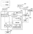
図1は、実施の形態に係るコントローラおよび蓄電システムを含むシステムを説明するためのブロック図である。 FIG. 1 is a block diagram for explaining a system including a controller and a power storage system according to an embodiment.
コントローラ100は、蓄電システム200を制御する制御装置である。具体的には、コントローラ100は、蓄電システム200が備える第1のDC/DCコンバータ210、双方向インバータ220、及び、第2のDC/DCコンバータ230を制御する。コントローラ100と、蓄電システム200が備える第1のDC/DCコンバータ210、双方向インバータ220、および、第2のDC/DCコンバータ230とは、通信可能に接続されている。例えば、コントローラ100と、蓄電システム200が備える第1のDC/DCコンバータ210、双方向インバータ220、及び、第2のDC/DCコンバータ230とは、制御線(配線)によって通信可能に接続されている。また、例えば、コントローラ100と、蓄電システム200が備える第1のDC/DCコンバータ210、双方向インバータ220、および、第2のDC/DCコンバータ230とは、無線によって通信可能に接続されていてもよい。つまり、コントローラ100と、蓄電システム200が備える他の構成要素とは、1つの筐体に一体的に構成されてもよいし、別体で構成されてもよい。つまり、コントローラ100は、いわゆるリモートコントローラでもよい。
The
蓄電システム200は、第1のDC/DCコンバータ210とDC(Direct Current)バスである電力線で接続される、リチウムイオン電池、鉛蓄電池などの蓄電池300の充放電を制御するための装置である。例えば、コントローラ100は、双方向インバータ220とAC(Alternated Current)バスである電力線で接続される分電盤500を介して、外部商用電源である系統電源600からの電力を充電する場合には、双方向インバータ220の電力変換の向きを制御する。具体的には、コントローラ100は、系統電源600から供給される交流(AC)電力を直流(DC)電力に変換し、第1のDC/DCコンバータ210へ出力する。コントローラ100は、第1のDC/DCコンバータ210で当該DC電力の電圧を制御して蓄電池300を充電させる。また、コントローラ100は、蓄電池300に充電された電力を分電盤500と接続された電化製品などの負荷520に供給する場合、双方向インバータ220を制御して蓄電池300から供給されるDC電力をAC電力に変換して系統電源600側へ出力する。
The
また、蓄電システム200では、PV(Photovoltaics:太陽電池モジュール)である第1のPV(第1の太陽電池モジュール)400と双方向インバータ220とが、PCS(パワーコンディショナ)510、分電盤500を介してACバスで接続される場合がある。また、蓄電システム200では、PVである第2のPV(第2の太陽電池モジュール)410と第2のDC/DCコンバータ230とが直接接続される場合がある。つまり、蓄電システム200は、蓄電池300及び第2のPV410と接続可能なハイブリットパワーコンディショナである。コントローラ100は、第1のPV400および/または第2のPV410が蓄電システム200と接続されているか否かに応じて、第1のPV400および/または第2のPV410で発電される電力の蓄電池300への充電を制御する。
Further, in the
コントローラ100は、制御回路110と、操作部120と、表示部130とを備える。
The
制御回路110は、蓄電システム200と接続される蓄電池300の充放電を制御する。制御回路110は、例えば、CPU(Central Processing Unit)、とCPUが実行する制御プログラムが格納された記憶装置(不図示)によって実現される。記憶装置としては、ROM(Read Only Memory)、RAM(Random Access Memory)、HDD(Hard Disk Drive)、フラッシュメモリなどが例示される。なお、制御回路110は、ゲートアレイ等を用いた専用の電子回路によってハードウェア的に実現されてもよい。
The
制御回路110は、双方向インバータ220にACバスを介して第1のPV400が接続されている第1の状態であるか否かに応じて、双方向インバータ220における電力変換の向きを制御する。具体的には、制御回路110は、第1の状態であるか否かを判定し、第1の状態であるか否かの判定結果に応じて、双方向インバータ220における電力変換の向きを制御する。図1においては、双方向インバータ220は、分電盤500、PCS510を介して、第1のPV400と接続されている。つまり、図1に示される蓄電システム200の状態は、第1の状態を満たしている。
The
また、制御回路110は、蓄電システム200が第1の状態である場合であって、双方向インバータ220と系統電源600との間の経路における電流の流れが逆潮流方向であるか否かを判定する。ここで、逆潮流方向とは、蓄電システム200から系統電源600側へ流れる電流の向きである(図4に示す逆潮流方向R)。より具体的には、蓄電システム200と接続される分電盤500から系統電源600に向かう電流の方向である。制御回路110は、逆潮流方向に電流が流れていることを検出した場合に、双方向インバータ220がAC電力をDC電力に変換して出力できるように制御する。つまり、この場合に、制御回路110は、双方向インバータ220に入力されるAC電力を蓄電池300側へDC電力に変換して出力させる。
Further, the
また、制御回路110は、双方向インバータ220にDCバスを介して第2のPV410が接続されている第2の状態であるか否かを判定する。図1に示される蓄電システム200の状態は、第2の状態もまた満たしている。制御回路110は、蓄電システム200が第1の状態ではなく、かつ、第2の状態である場合であって、双方向インバータ220と系統電源600との間の経路における電流の流れが逆潮流方向の場合に、双方向インバータ220がAC電力をDC電力に変換して出力しないように制御する。つまり、この場合に、制御回路110は、分電盤500側から双方向インバータ220に入力され得るAC電力を蓄電池300側へDC電力に変換して出力しない。制御回路110は、例えば、系統電源600と分電盤500とを接続するACバスに流れる電流の向きを検出するCT(Current Trasformer)センサ530から逆潮流方向に電流が流れているか否かを示す信号を取得する。制御回路110は、当該信号から逆潮流方向に電流が流れているか否かを判定する。
Further, the
操作部120は、コントローラ100を操作するユーザからの指示を取得するための入力機構である。操作部120は、ユーザが操作可能に構成されていればよく、例えば、ボタン、タッチパネルなどにより実現される。制御回路110は、例えば、操作部120のユーザによる操作によって、第1の状態であるか否か、および、第2の状態であるか否かを判定する。
The
表示部130は、蓄電システム200と接続される蓄電池300の充電状態などを表示する表示装置である。表示部130は、例えば、ディスプレイである。
The
なお、操作部120の機能と表示部130の機能とは、例えば、タッチパネルディスプレイ等を用いて、一体的に形成されてもよい。つまり、当該タッチパネルディスプレイが、操作部120の機能と表示部130の機能とを有してもよい。
The function of the
図2は、実施の形態に係るコントローラ100が、ユーザから蓄電システム200と太陽電池モジュール(第1のPV400および第2のPV410)との接続状態を示す指示を取得する場合に、表示部130に表示させる画像の一例を示す図である。
FIG. 2 shows the
図2に示されるように、制御回路110は、ユーザから蓄電システム200に第1のPV400および/または第2のPV410が接続されているか否かを取得するために、表示部130に画像131を表示させる。ユーザは、操作部120を操作して、蓄電システム200が太陽電池モジュールと接続されているか否かを入力する。制御回路110は、ユーザに入力された第1のPV400および第2のPV410と蓄電システム200との接続状態に関する情報に基づいて、第1の状態であるか否か、および、第2の状態であるか否かを判定する。
As shown in FIG. 2, the
蓄電システム200は、コントローラ100と、第1のDC/DCコンバータ210と、双方向インバータと、第2のDC/DCコンバータ230とを備える。
The
第1のDC/DCコンバータ210は、蓄電池300とDCバスで接続され、蓄電池300に充放電される電力の電圧を制御するためのDC/DCコンバータである。
The first DC /
双方向インバータ220は、分電盤500を介して系統電源600、PCS510、負荷520などとACバスで接続される双方向DC/ACインバータである。また、双方向インバータ220は、第1のDC/DCコンバータ210を介して蓄電池300とDCバスで接続され、第2のDC/DCコンバータ230を介して第2のPV410とDCバスで接続される。例えば、双方向インバータ220は、系統電源600側から入力されるAC電力をDC電力に変換して蓄電池300側へ出力する。また、例えば、双方向インバータ220は、蓄電池300側から入力されるDC電力をAC電力に変換して負荷520へ出力する。
The
第2のDC/DCコンバータ230は、第2のPV410と接続され、第2のPV410で発電された電力の電圧を制御するためのDC/DCコンバータである。
The second DC /
[蓄電システムの制御]
続いて、制御回路110による蓄電システム200の各構成要素の制御の詳細について説明する。
[Control of power storage system]
Subsequently, the details of the control of each component of the
<充電制御の設定>
蓄電システム200が負荷520に電力を供給する状態となっている場合に、蓄電システム200に、第2のPV410、および、第1のPV400が電気的に接続されているとき、第2のPV410で発電された電力は、第2のDC/DCコンバータ230、双方向インバータ220、および、分電盤500を介して負荷520へ送電される。また、第1のPV400で発電された電力は、PCS510、分電盤500を介して負荷520へ送電される。この際に、第1のPV400および/または第2のPV410で発電された電力量が、負荷520が消費する電力量を上回る場合がある。制御回路110は、このように第1のPV400および/または第2のPV410で余剰に電力が発電された場合には、双方向インバータ220を制御して、発電された余剰の電力を蓄電池300に充電させる。言い換えると、制御回路110は、第1のPV400および/または第2のPV410で余剰に電力が発電された場合には、双方向インバータ220を制御して、発電された余剰の電力を蓄電池300に充電させる充電モードを有する。
<Charge control settings>
When the
なお、制御回路110が、第1のPV400および/または第2のPV410で余剰に電力が発電されたと判定する方法は、特に限定されない。例えば、制御回路110は、第1のPV400および/または第2のPV410が予め定められた電力量よりも発電した場合に、余剰に電力が発電されたと判定してもよい。また、例えば、制御回路110は、逆潮流方向に流れる電流を検出した場合に、余剰に電力が発電されたと判定してもよい。この場合の詳細については、後述する。
The method by which the
図3は、実施の形態に係るコントローラ100における、蓄電システム200の制御方法を決定する処理手順を示すフローチャートである。
FIG. 3 is a flowchart showing a processing procedure for determining a control method of the
制御回路110は、双方向インバータ220が第1のPV400に接続されているか否かを判定する(ステップS101)。言い換えると、制御回路110は、蓄電システム200が第1の状態であるか否かを判定する。
The
制御回路110は、双方向インバータ220が第1のPV400に接続されていると判定した場合(ステップS101でYes)、双方向インバータ220によるAC電力からDC電力への電力変換を可能とする(ステップS102)。つまり、制御回路110は、第1のPV400が発電した電力が、負荷520が消費する電力量を超えて余剰電力が発生した場合、双方向インバータ220に送電されてきたAC電力を、双方向インバータ220によってDC電力へ変換させることを可能とする。制御回路110は、このように双方向インバータ220で変換させたDC電力を、蓄電池300を充電させることを可能とする。
When the
一方、制御回路110は、双方向インバータ220が第1のPV400に接続されていないと判定した場合(ステップS101でNo)、双方向インバータ220によるAC電力からDC電力への電力変換を不可とする(ステップS102)。蓄電システム200が第1の状態ではない場合に、余剰電力が発生している場合は、蓄電システム200からの送電によるものと想定される。そのために、制御回路110は、蓄電システム200が第1の状態でないと判定した場合には、双方向インバータ220によるAC電力からDC電力への電力変換をしない。この場合には、制御回路110は、双方向インバータ220における、DC側からAC側への電力の供給の制御、および、双方向インバータ220の電力の供給の停止の制御のみを行う。前者により余剰電力の系統電源600への逆潮流による売電が実施され、後者により余剰電力の蓄電池300への充電が実施される。
On the other hand, when the
なお、蓄電システム200が第1の状態および第2の状態を満たす場合には、ユーザが操作部120を操作することによって、制御回路110が制御する双方向インバータ220の電力の変換方法が設定されてもよい。具体的には、蓄電システム200が第1の状態および第2の状態を満たす場合には、第2のPV410で発電された電力のみを蓄電池300へ充電することをユーザが任意に設定できてもよい。この場合、第1のPV400で発電された電力は蓄電池300へ充電されないことを設定することと同じである。例えば、制御回路110は、このように第2のPV410で発電された電力のみを蓄電池300に充電することをユーザに選択させるための表示を表示部130に表示させてもよい。或いは、蓄電システム200が第1の状態および第2の状態を満たす場合には、第2のPV410で発電された電力のみを充電するか、第1のPV400および第2のPV410で発電された電力を充電するかのいずれかの制御方法が予め定められていてもよい。この場合には、制御回路110は、予め定められた制御方法にしたがって、蓄電池300への充電を行う。
When the
図4は、実施の形態に係るコントローラ100が、ユーザから蓄電池300の充電方法を示す指示を取得する場合に、表示部130に表示させる画像の一例を示す図である。
FIG. 4 is a diagram showing an example of an image to be displayed on the
図4に示されるように、制御回路110は、例えば、図2に示す画像131を表示部130に表示させ、ユーザから指示を取得した後に、蓄電池300の充電方法をユーザに選択させるための画像132を表示部130に表示させる。
As shown in FIG. 4, the
例えば、ユーザが「環境優先モード」を選択した場合、制御回路110は、第1のPV400および/または第2のPV410で発電された電力量が、負荷520が消費する電力量に対して過剰となったときに、蓄電池300を第1のPV400および/または第2のPV410からの電力で充電させる。
For example, when the user selects the "environmental priority mode", the
なお、制御回路110は、蓄電システム200と第1のPV400および第2のPV410の双方とが接続されていない場合、「環境優先モード」の表示をしないように表示部130を制御してもよい。
The
また、制御回路110は、上述した「環境優先モード」の他に、蓄電池300を充電させるモードを有していてもよい。例えば、ユーザが、図4に示す「蓄電優先モード」を選択した場合には、蓄電池300が常に満充電となるように、第1のDC/DCコンバータ210、第2のDC/DCコンバータ230、および、双方向インバータ220を制御してもよい。この場合には、制御回路110は、第1のPV400、第2のPV410、および、系統電源600から供給される電力で蓄電池300を充電させてもよい。
Further, the
<逆潮流検出時の充電制御>
続いて、制御回路110が逆潮流を検出した場合における、双方向インバータ220の制御の詳細について説明する。
<Charging control when reverse power flow is detected>
Subsequently, the details of the control of the
図5は、実施の形態に係る蓄電システム200が、第1のPV400および第2のPV410と接続されている場合の電力の流れの一例を示すブロック図である。つまり、図5に示す蓄電システム200は、第1の状態および第2の状態を満たす。なお、図5に示す太線の矢印の方向に第1のPV400および第2のPV410で発電された電力が送電されているものとする。
FIG. 5 is a block diagram showing an example of the flow of electric power when the
図5に示すように、蓄電システム200が負荷520に電力を供給する状態となっている場合、第1のPV400で発電された電力は、分電盤500を介して負荷520へ送電される。また、第2のPV410で発電された電力は、第2のDC/DCコンバータ230、双方向インバータ220、および、分電盤500を介して負荷520へ送電される。この際に、第1のPV400および第2のPV410で発電された電力量が、負荷520が消費する電力量を上回る場合、売電する設定ではないにもかかわらず、逆潮流方向R(図5に示す点線矢印の方向)である系統電源600側へ送電されてしまう場合がある。制御回路110は、このように第1のPV400および/または第2のPV410で余剰に電力が発電された場合には、双方向インバータ220を制御して、発電された余剰の電力を蓄電池300に充電させる。つまり、制御回路110は、蓄電システム200が負荷520に電力を供給する状態となっている場合に、逆潮流方向Rへの送電が検出されたときに、第1のPV400および/または第2のPV410で余剰に電力が発電されたと判定する。
As shown in FIG. 5, when the
図6は、実施の形態に係る蓄電システム200が第1の状態を満たす場合における、逆潮流を検出したときの電力の流れの一例を示すブロック図である。
FIG. 6 is a block diagram showing an example of a power flow when reverse power flow is detected when the
図6に示されるように、制御回路110は、逆潮流方向Rへの送電を検出した場合、双方向インバータ220をACバス側からDCバス側へと電力が流れるように制御する。つまり、この場合には、制御回路110は、双方向インバータ220がAC電力をDC電力に変換して出力するように制御する。こうすることで、逆潮流方向Rに流れる余剰の電力を、蓄電池300へ充電させる。
As shown in FIG. 6, when the
図7は、実施の形態に係る蓄電システム200が第1の状態を満たさず、かつ、第2の状態を満たす場合における、逆潮流を検出したときの電力の流れの一例を示すブロック図である。
FIG. 7 is a block diagram showing an example of the power flow when reverse power flow is detected when the
図7に示されるように、図6とは異なり、蓄電システム200は、第1のPV400とは、接続されていない。つまり、図7に示される蓄電システム200は、第1の状態を満たさず、かつ、第2の状態を満たす。この場合には、制御回路110は、逆潮流方向Rへの送電を検出した場合においても、第1のPV400が余剰に電力を発電しているわけではないため、双方向インバータ220をACバス側からDCバス側(図6に示す1点鎖線の矢印方向)へと電力が流れるように制御しない。つまり、この場合には、制御回路110は、双方向インバータ220がAC電力をDC電力に変換して出力しないように制御する。
As shown in FIG. 7, unlike FIG. 6, the
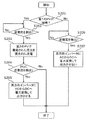
図8は、実施の形態に係る蓄電システム200が、第2の状態を満たす場合における、逆潮流を検出した場合におけるコントローラ100が実行する双方向インバータ220の制御の処理手順の一例を示すフローチャートである。
FIG. 8 is a flowchart showing an example of a processing procedure for controlling the
制御回路110は、双方向インバータ220にACバスを介して第1のPV400が接続されている状態である第1の状態であるか否かを判定する(ステップS201)。
The
制御回路110は、第1の状態であると判定した場合に(ステップS201でYes)、逆潮流を検出したか否かを判定する(ステップS202)。
When the
制御回路110は、逆潮流を検出していないと判定した場合(ステップS202でNo)、ステップS202の判定を繰り返す。
When the
一方、制御回路110は、逆潮流を検出したと判定した場合(ステップS202でYes)、第2のPV410で発電された電力を優先的に充電させる。具体的には、制御回路110は、ステップS203において、双方向インバータ220にAC電力からDC電力への変換はさせず、第2のDC/DCコンバータ230を制御して、第2のPV410で発電された余剰電力を蓄電池300に充電させる。
On the other hand, when the
次に、制御回路110は、さらに逆潮流を検出したか否かを判定する(ステップS204)。つまり、ステップS204では、制御回路110は、第2のPV410で発電された余剰電力を蓄電池300に充電させているにもかかわらず、まだ逆潮流が検出されるか否かを判定する。
Next, the
制御回路110は、さらに逆潮流を検出した場合(ステップS204でYes)、双方向インバータ220に入力されるAC電力をDC電力に電力変換して出力させる(ステップS205)。こうすることで、制御回路110は、第1のPV400で発生した余剰な電力を蓄電池300に送電して充電させる。
When the
また、制御回路110は、第1の状態ではないと判定した場合に(ステップS201でNo)、逆潮流を検出したか否かを判定する(ステップS206)。
Further, the
制御回路110は、逆潮流を検出していないと判定した場合(ステップS206でNo)、ステップS205の判定を繰り返す。
When the
一方、制御回路110は、逆潮流を検出したと判定した場合(ステップS206でYes)、双方向インバータ220に入力されるAC電力をDC電力に電力変換をさせない(ステップS207)。つまり、制御回路110は、第1の状態ではない場合に、逆潮流を検出したとき、双方向インバータ220を介して蓄電池300を充電させる制御をしない。このような場合には、例えば、制御回路110は、第1のDC/DCコンバータ210、および/または第2のDC/DCコンバータ230を制御して、第2のPV410で発生した余剰な電力を蓄電池300へ充電させてもよい。また、制御回路110は、双方向インバータ220を制御して、双方向インバータ220におけるDC側からAC側へ流れる電力量を制限してもよい。
On the other hand, when the
なお、ステップS203において、蓄電システム200が第2の状態も満たす場合には、ユーザが操作部120を操作することによって、制御回路110が制御する双方向インバータ220の電力の変換方法が設定されてもよい。具体的には、蓄電システム200が第1の状態および第2の状態を満たす場合には、第2のPV410で発電された余剰な電力のみか、もしくは第1のPV400および第2のPV410の両方で発電された余剰な電力を蓄電池300へ充電させるかをユーザが任意に設定できてもよい。
In step S203, when the
図9は、実施の形態に係る蓄電システム200が第1の状態を満たし、かつ、第2の状態を満たさない場合における、逆潮流を検出したときの電力の流れの一例を示すブロック図である。
FIG. 9 is a block diagram showing an example of the power flow when reverse power flow is detected when the
図9に示されるように、例えば図6とは異なり、蓄電システム200は、第1のPV400とは接続されているが、第2のPV410とは接続されていない。つまり、図9に示される蓄電システム200は、第1の状態を満たし、かつ、第2の状態を満たさない。この場合には、制御回路110は、逆潮流方向Rへの送電を検出した場合においては、第2のPV410が接続されていないために、第1のPV400が余剰に電力を発電していると想定される。そのために、この場合は、双方向インバータ220をACバス側からDCバス側へと電力が流れるように制御する。こうすることで、制御回路110は、第1のPV400で発生した余剰な電力を蓄電池300に送電して充電させる。
As shown in FIG. 9, unlike FIG. 6, for example, the
図10は、実施の形態に係る蓄電システムが、第2の状態を満たさない場合における、逆潮流を検出した場合におけるコントローラが実行する双方向インバータ制御の処理手順の一例を示すフローチャートである。 FIG. 10 is a flowchart showing an example of a bidirectional inverter control processing procedure executed by the controller when reverse power flow is detected when the power storage system according to the embodiment does not satisfy the second state.
制御回路110は、双方向インバータ220にACバスを介して第1のPV400が接続されている状態である第1の状態であるか否かを判定する(ステップS301)。
The
制御回路110は、第1の状態であると判定した場合に(ステップS301でYes)、逆潮流を検出したか否かを判定する(ステップS302)。
When the
制御回路110は、逆潮流を検出していないと判定した場合(ステップS302でNo)、ステップS302の判定を繰り返す。
When the
一方、制御回路110は、逆潮流を検出したと判定した場合(ステップS302でYes)、双方向インバータ220に入力されるAC電力をDC電力に電力変換して出力させる(ステップS303)。
On the other hand, when the
また、制御回路110は、第1の状態ではないと判定した場合に(ステップS301でNo)、蓄電システム200に第1のPV400および第2のPV410が接続されていないと判定し、動作を終了する。
Further, when the
[効果等]
以上のように、実施の形態に係るコントローラ100は、蓄電池300に接続された第1のDC/DCコンバータ210、及び、第1のDC/DCコンバータ210に接続された双方向インバータ220を備える蓄電システム200におけるコントローラである。コントローラ100は、双方向インバータ220と通信可能に構成され、双方向インバータ220にACバスを介して第1のPV400が接続されている第1の状態であるか否かに応じて、双方向インバータ220における電力変換の向きを制御する制御回路110を備える。
[Effects, etc.]
As described above, the
このような構成によれば、コントローラ100は、蓄電システム200と第1のPV400との接続状態に応じて、双方向インバータ220の制御方法を決定することができる。具体的には、コントローラ100は、第1のPV400で発電されたDC電力を、PCS510等によるAC電力への変換を介して、蓄電池300に充電させる制御をすることができる。
According to such a configuration, the
また、制御回路110は、第1の状態である場合であって、双方向インバータ220と系統電源600との間の経路における電流の流れが逆潮流方向Rの場合に、双方向インバータ220が交流電力を直流電力に変換して出力できるように制御してもよい。
Further, the
このような構成によれば、制御回路110は、逆潮流方向に電流が流れている場合に、第1のPV400で余剰の電力が発電されていると判定できる。そのために、制御回路110は、逆潮流を検出したか否かの判定結果に応じて、双方向インバータ220および第1のDC/DCコンバータ210を制御することで、第1のPV400で余剰に発電された電力を蓄電池300に充電させることができる。つまり、このような構成によれば、コントローラ100は、簡便な構成で、第1のPV400で余剰に発電された電力を蓄電池300に充電可能に制御できる。
According to such a configuration, the
また、制御回路110は、第1の状態ではなく、かつ、双方向インバータ220に、DCバスを介して第2のPV410が接続されている第2の状態である場合であって、双方向インバータ220と系統電源600との間の経路における電流の流れが逆潮流方向Rの場合に、双方向インバータ220がAC電力をDC電力に変換して出力しないように制御してもよい。
Further, the
このような構成によれば、制御回路110は、逆潮流方向に電流が流れている場合に、第2のPV410で余剰の電力が発電されていると判定できる。そのために、制御回路110は、逆潮流を検出したか否かの判定結果に応じて、第2のDC/DCコンバータ230および第1のDC/DCコンバータ210を制御することで、蓄電池300に当該余剰の電力を充電させることができる。さらに、制御回路110は、双方向インバータ220のAC電力からDC電力へ電力を変換して出力しないように制御することで、系統電源600から蓄電池300へ電力が供給されることを抑制することができる。
According to such a configuration, the
つまり、このような構成によれば、コントローラ100は、太陽電池モジュールで発電されたDC電力を、AC電力へ変換せずに蓄電池300に充電させる方法を選択できる。具体的には、コントローラ100は、簡便な構成で、第2のPV410で余剰に発電された電力を蓄電池300へ充電可能に制御できる。
That is, according to such a configuration, the
また、コントローラ100は、ユーザが操作可能に構成された操作部120をさらに備えてもよい。この場合に、制御回路110は、操作部120のユーザによる操作によって、第1の状態であるか否か、及び、第2の状態であるか否かを判定してもよい。
Further, the
このような構成によれば、制御回路110は、簡便な構成で、操作部120が取得した指示に応じて、蓄電システム200と第1のPV400および第2のPV410との接続状態を判定することができる。
According to such a configuration, the
また、本発明の一態様に係る蓄電システム200は、コントローラ100と、第1のDC/DCコンバータ210と、双方向インバータ220と、第1のPV400に接続された第2のDC/DCコンバータ230とを備える。
Further, the
このような構成によれば、蓄電システム200は、蓄電システム200と第1のPV400との接続状態に応じて、双方向インバータ220および第1のDC/DCコンバータ210を制御することができる。そのため、蓄電システム200は、第1のPV400で発電されたDCがPCS510などに変換されたAC電力を、蓄電システム200に接続された蓄電池300へ充電可能に制御できる。
According to such a configuration, the
また、本発明の一態様に係るプログラムは、双方向インバータ220を備える蓄電システム200を制御するための制御方法をコンピュータに実行させるためのプログラムである。本発明の一態様に係るプログラムは、双方向インバータ220にACバスを介して第1のPV400が接続されている状態であるか否かに応じて、双方向インバータ220における電力変換の向きを制御する制御方法を含む。
Further, the program according to one aspect of the present invention is a program for causing a computer to execute a control method for controlling a
このような構成によれば、蓄電システム200と第1のPV400との接続状態に応じて、双方向インバータ220を制御することができるプログラムが実現される。そのため、当該プログラムを実行するコントローラ100などのコンピュータによれば、第1のPV400と接続されたPCS510によってDC電力が変換されたAC電力を蓄電池300に充電可能に制御できる。
According to such a configuration, a program capable of controlling the
(他の実施の形態)
以上、実施の形態に係るコントローラ、蓄電システムおよびプログラムについて説明したが、本発明は、上記実施の形態に限定されるものではない。
(Other embodiments)
Although the controller, the power storage system, and the program according to the embodiment have been described above, the present invention is not limited to the above embodiment.
例えば、蓄電システム200は、第2のDC/DCコンバータ230を備えていなくてもよい。この場合、制御回路110が、第2の状態であることを判定することは、蓄電システム200に、第2のDC/DCコンバータ230及び第2のPV410が接続されていることを判定することを意味する。
For example, the
各実施の形態に対して当業者が思いつく各種変形を施して得られる形態、または、本発明の趣旨を逸脱しない範囲で各実施の形態における構成要素及び機能を任意に組み合わせることで実現される形態も本発明に含まれる。 A form obtained by applying various modifications to each embodiment that can be conceived by those skilled in the art, or a form realized by arbitrarily combining the components and functions of each embodiment without departing from the spirit of the present invention. Is also included in the present invention.
100 コントローラ
110 制御回路
120 操作部
200 蓄電システム
210 第1のDC/DCコンバータ
220 双方向インバータ
230 第2のDC/DCコンバータ
300 蓄電池
400 第1のPV(第1の太陽電池モジュール)
410 第2のPV(第2の太陽電池モジュール)
600 系統電源
R 逆潮流方向
100
410 Second PV (second solar cell module)
600 system power supply R Reverse power flow direction
Claims (5)
前記双方向インバータと通信可能に構成される制御回路を備え、
前記制御回路は、
前記双方向インバータにACバスを介して第1の太陽電池モジュールが接続されている第1の状態であるか否かを示す情報に基づいて前記第1の状態であるか否かを判定し、且つ、前記双方向インバータと系統電源との間の経路における電流の流れを検出する電流センサの検出結果に基づいて前記経路における電流の流れが逆潮流方向であるか否かを判定し、
前記第1の状態ではないと判定した場合、前記双方向インバータにDCバス及び前記第2のDC/DCコンバータを介して第2の太陽電池モジュールが接続されている第2の状態であるか否かを示す情報に基づいて前記第2の状態であるか否かを判定し、
前記第2の状態であると判定し、且つ、前記経路における電流の流れが逆潮流方向であると判定した場合、前記双方向インバータが交流電力を直流電力に変換して前記双方向インバータから前記第1のDC/DCコンバータに向けて電流を出力しないように前記双方向インバータを制御し、且つ、前記第1のDC/DCコンバータ及び前記第2のDC/DCコンバータから前記蓄電池に向けて電流を出力できるように、前記第1のDC/DCコンバータと前記第2のDC/DCコンバータを制御する、
コントローラ。 A first DC / DC converter connected to a storage battery, a second DC / DC converter connected to the first DC / DC converter, and a bidirectional inverter connected to the first DC / DC converter. A controller in a power storage system equipped with
A control circuit that will be configured to communicate with the bidirectional inverter,
The control circuit
Based on the information indicating whether or not the first solar cell module is connected to the bidirectional inverter via the AC bus in the first state, it is determined whether or not the first state is in the first state. Further, based on the detection result of the current sensor that detects the current flow in the path between the bidirectional inverter and the system power supply, it is determined whether or not the current flow in the path is in the reverse power flow direction.
If it is determined that the first state is not present, whether or not the second state is in which the second solar cell module is connected to the bidirectional inverter via the DC bus and the second DC / DC converter. Based on the information indicating whether or not it is in the second state, it is determined whether or not it is in the second state.
When it is determined that the second state is present and the current flow in the path is in the reverse power flow direction, the bidirectional inverter converts AC power into DC power and the bidirectional inverter converts the current to DC power. The bidirectional inverter is controlled so as not to output a current toward the first DC / DC converter, and the current from the first DC / DC converter and the second DC / DC converter toward the storage battery. The first DC / DC converter and the second DC / DC converter are controlled so that
controller.
請求項1に記載のコントローラ。 Wherein the control circuit determines that the in a first state, and pre-conversion when the current flow in Kikei path determined to be the reverse flow direction, the bidirectional inverter AC power into DC power Then, the bidirectional inverter is controlled so that the bidirectional inverter can output power to the first DC / DC converter.
The controller according to claim 1.
前記制御回路は、前記操作部のユーザによる操作によって、前記第1の状態であるか否か、及び、前記第2の状態であるか否かを判定する、
請求項1又は2に記載のコントローラ。 The controller further includes an operation unit configured to be operable by the user.
The control circuit determines whether or not it is in the first state and whether or not it is in the second state by an operation by the user of the operation unit.
The controller according to claim 1 or 2.
前記第1のDC/DCコンバータと、
前記双方向インバータと、
前記第2の太陽電池モジュールに接続された前記第2のDC/DCコンバータと、を備える、
蓄電システム。 The controller according to any one of claims 1 to 3.
With the first DC / DC converter
With the bidirectional inverter
And a second DC / DC converter connected to said second solar cell module,
Power storage system.
前記双方向インバータにACバスを介して第1の太陽電池モジュールが接続されている第1の状態であるか否かを示す情報に基づいて前記第1の状態であるか否かを判定し、且つ、前記双方向インバータと系統電源との間の経路における電流の流れを検出する電流センサの検出結果に基づいて前記経路における電流の流れが逆潮流方向であるか否かを判定し、
前記第1の状態ではないと判定した場合、前記双方向インバータにDCバス及び前記第2のDC/DCコンバータを介して第2の太陽電池モジュールが接続されている第2の状態であるか否かを示す情報に基づいて前記第2の状態であるか否かを判定し、
前記第2の状態であると判定し、且つ、前記経路における電流の流れが逆潮流方向であると判定した場合、前記双方向インバータが交流電力を直流電力に変換して前記双方向インバータから前記第1のDC/DCコンバータに向けて電流を出力しないように前記双方向インバータを制御し、且つ、前記第1のDC/DCコンバータ及び前記第2のDC/DCコンバータから前記蓄電池に向けて電流を出力できるように、前記第1のDC/DCコンバータと前記第2のDC/DCコンバータとを制御する制御方法をコンピュータに実行させるための
プログラム。 A first DC / DC converter connected to a storage battery, a second DC / DC converter connected to the first DC / DC converter, and a bidirectional inverter connected to the first DC / DC converter. It is a program for controlling a power storage system equipped with
Based on the information indicating whether or not the first solar cell module is connected to the bidirectional inverter via the AC bus in the first state, it is determined whether or not the first state is in the first state. Further, based on the detection result of the current sensor that detects the current flow in the path between the bidirectional inverter and the system power supply, it is determined whether or not the current flow in the path is in the reverse power flow direction.
If it is determined that the first state is not present, whether or not the second state is in which the second solar cell module is connected to the bidirectional inverter via the DC bus and the second DC / DC converter. Based on the information indicating whether or not it is in the second state, it is determined whether or not it is in the second state.
When it is determined that the second state is present and the current flow in the path is in the reverse power flow direction, the bidirectional inverter converts AC power into DC power and the bidirectional inverter converts the current to DC power. The bidirectional inverter is controlled so as not to output a current toward the first DC / DC converter, and the current from the first DC / DC converter and the second DC / DC converter toward the storage battery. A program for causing a computer to execute a control method for controlling the first DC / DC converter and the second DC / DC converter so that the current can be output.
Priority Applications (1)
| Application Number | Priority Date | Filing Date | Title |
|---|---|---|---|
| JP2017100304A JP6851030B2 (en) | 2017-05-19 | 2017-05-19 | Controllers, power storage systems and programs |
Applications Claiming Priority (1)
| Application Number | Priority Date | Filing Date | Title |
|---|---|---|---|
| JP2017100304A JP6851030B2 (en) | 2017-05-19 | 2017-05-19 | Controllers, power storage systems and programs |
Publications (2)
| Publication Number | Publication Date |
|---|---|
| JP2018196295A JP2018196295A (en) | 2018-12-06 |
| JP6851030B2 true JP6851030B2 (en) | 2021-03-31 |
Family
ID=64571915
Family Applications (1)
| Application Number | Title | Priority Date | Filing Date |
|---|---|---|---|
| JP2017100304A Active JP6851030B2 (en) | 2017-05-19 | 2017-05-19 | Controllers, power storage systems and programs |
Country Status (1)
| Country | Link |
|---|---|
| JP (1) | JP6851030B2 (en) |
Families Citing this family (1)
| Publication number | Priority date | Publication date | Assignee | Title |
|---|---|---|---|---|
| JP7415406B2 (en) * | 2019-10-01 | 2024-01-17 | 株式会社Gsユアサ | Charging device, operating method, charging system, and charge/discharge control method |
Family Cites Families (5)
| Publication number | Priority date | Publication date | Assignee | Title |
|---|---|---|---|---|
| JP5546832B2 (en) * | 2009-11-16 | 2014-07-09 | パナソニック株式会社 | Power distribution system |
| JP5473141B2 (en) * | 2010-08-31 | 2014-04-16 | ニチコン株式会社 | Storage power conditioner system |
| JP6138449B2 (en) * | 2012-10-09 | 2017-05-31 | シャープ株式会社 | Power supply system, terminal device, and control method of power supply system |
| JP2015198555A (en) * | 2014-04-03 | 2015-11-09 | シャープ株式会社 | Power control method, power control unit, and power control system |
| JP6363412B2 (en) * | 2014-07-03 | 2018-07-25 | シャープ株式会社 | Power conditioner and power control method |
-
2017
- 2017-05-19 JP JP2017100304A patent/JP6851030B2/en active Active
Also Published As
| Publication number | Publication date |
|---|---|
| JP2018196295A (en) | 2018-12-06 |
Similar Documents
| Publication | Publication Date | Title |
|---|---|---|
| JP5655167B2 (en) | Power management apparatus and program | |
| JP6956384B2 (en) | Charge control system, power supply system, charge control method, program | |
| JP5520256B2 (en) | MICROGRID, ITS CONTROL DEVICE, AND ITS CONTROL METHOD | |
| JP6648614B2 (en) | Power storage device | |
| JPWO2014208561A1 (en) | CHARGE STATE MANAGEMENT METHOD, CHARGE STATE MANAGEMENT DEVICE, AND PROGRAM | |
| JP6803537B2 (en) | Voltage control device and voltage control method | |
| JP2017085781A (en) | Power supply system | |
| CN103246336A (en) | Electronic apparatus and driving control method thereof | |
| JP2014023276A (en) | Storage battery control system | |
| JP6851030B2 (en) | Controllers, power storage systems and programs | |
| JP7042435B2 (en) | Controllers, power storage systems and programs | |
| KR102029030B1 (en) | Apparatus and method for controlling drive of energy storage system considering both long term and short term characteristics | |
| JP2017028969A (en) | Power management device | |
| JP6459811B2 (en) | Power supply system, charge / discharge control device, and charge / discharge control method | |
| WO2017163747A1 (en) | Power storage system, charge/discharge control device, control method therefor, and program | |
| JP2011083059A (en) | Storage battery operation controller of power supply system | |
| JP2018160950A (en) | Power supply system | |
| CN110352531B (en) | Energy level conversion circuit for portable energy storage device | |
| JP6677665B2 (en) | Power supply system and power supply system control method | |
| JP5862750B2 (en) | Power control system, power control method, control device, program, and server device | |
| JP6016719B2 (en) | Charge control system | |
| JP2018125974A (en) | Storage battery control device | |
| JP2006180660A (en) | Photovoltaic power generating system | |
| JP6969391B2 (en) | Energy storage control device | |
| JP2023165442A (en) | Power supply system and power conversion device |
Legal Events
| Date | Code | Title | Description |
|---|---|---|---|
| A621 | Written request for application examination |
Free format text: JAPANESE INTERMEDIATE CODE: A621 Effective date: 20200120 |
|
| A977 | Report on retrieval |
Free format text: JAPANESE INTERMEDIATE CODE: A971007 Effective date: 20201015 |
|
| A131 | Notification of reasons for refusal |
Free format text: JAPANESE INTERMEDIATE CODE: A131 Effective date: 20201027 |
|
| A521 | Written amendment |
Free format text: JAPANESE INTERMEDIATE CODE: A523 Effective date: 20201221 |
|
| TRDD | Decision of grant or rejection written | ||
| A01 | Written decision to grant a patent or to grant a registration (utility model) |
Free format text: JAPANESE INTERMEDIATE CODE: A01 Effective date: 20210209 |
|
| A61 | First payment of annual fees (during grant procedure) |
Free format text: JAPANESE INTERMEDIATE CODE: A61 Effective date: 20210222 |
|
| R151 | Written notification of patent or utility model registration |
Ref document number: 6851030 Country of ref document: JP Free format text: JAPANESE INTERMEDIATE CODE: R151 |