JP6719604B2 - Power distribution equipment and power distribution method - Google Patents
Power distribution equipment and power distribution method Download PDFInfo
- Publication number
- JP6719604B2 JP6719604B2 JP2019004009A JP2019004009A JP6719604B2 JP 6719604 B2 JP6719604 B2 JP 6719604B2 JP 2019004009 A JP2019004009 A JP 2019004009A JP 2019004009 A JP2019004009 A JP 2019004009A JP 6719604 B2 JP6719604 B2 JP 6719604B2
- Authority
- JP
- Japan
- Prior art keywords
- power
- grid
- power distribution
- load
- fixed end
- Prior art date
- Legal status (The legal status is an assumption and is not a legal conclusion. Google has not performed a legal analysis and makes no representation as to the accuracy of the status listed.)
- Active
Links
- 238000009826 distribution Methods 0.000 title claims description 167
- 238000000034 method Methods 0.000 title claims description 39
- 238000010248 power generation Methods 0.000 claims description 52
- 238000004146 energy storage Methods 0.000 claims description 38
- 230000007935 neutral effect Effects 0.000 claims description 36
- 230000002159 abnormal effect Effects 0.000 claims description 30
- 230000003750 conditioning effect Effects 0.000 claims description 17
- 238000005520 cutting process Methods 0.000 claims description 7
- 238000007599 discharging Methods 0.000 claims description 2
- 238000010586 diagram Methods 0.000 description 15
- 238000006243 chemical reaction Methods 0.000 description 14
- 230000005611 electricity Effects 0.000 description 4
- 230000004048 modification Effects 0.000 description 3
- 238000012986 modification Methods 0.000 description 3
- 230000003044 adaptive effect Effects 0.000 description 2
- 238000005034 decoration Methods 0.000 description 1
- 230000007812 deficiency Effects 0.000 description 1
- 238000005516 engineering process Methods 0.000 description 1
- 230000007613 environmental effect Effects 0.000 description 1
- 239000000446 fuel Substances 0.000 description 1
- 238000003892 spreading Methods 0.000 description 1
- 230000000007 visual effect Effects 0.000 description 1
- 238000005303 weighing Methods 0.000 description 1
Images


Classifications
-
- H—ELECTRICITY
- H02—GENERATION; CONVERSION OR DISTRIBUTION OF ELECTRIC POWER
- H02J—CIRCUIT ARRANGEMENTS OR SYSTEMS FOR SUPPLYING OR DISTRIBUTING ELECTRIC POWER; SYSTEMS FOR STORING ELECTRIC ENERGY
- H02J9/00—Circuit arrangements for emergency or stand-by power supply, e.g. for emergency lighting
- H02J9/04—Circuit arrangements for emergency or stand-by power supply, e.g. for emergency lighting in which the distribution system is disconnected from the normal source and connected to a standby source
- H02J9/06—Circuit arrangements for emergency or stand-by power supply, e.g. for emergency lighting in which the distribution system is disconnected from the normal source and connected to a standby source with automatic change-over, e.g. UPS systems
- H02J9/062—Circuit arrangements for emergency or stand-by power supply, e.g. for emergency lighting in which the distribution system is disconnected from the normal source and connected to a standby source with automatic change-over, e.g. UPS systems for AC powered loads
-
- H—ELECTRICITY
- H02—GENERATION; CONVERSION OR DISTRIBUTION OF ELECTRIC POWER
- H02J—CIRCUIT ARRANGEMENTS OR SYSTEMS FOR SUPPLYING OR DISTRIBUTING ELECTRIC POWER; SYSTEMS FOR STORING ELECTRIC ENERGY
- H02J3/00—Circuit arrangements for ac mains or ac distribution networks
-
- H—ELECTRICITY
- H02—GENERATION; CONVERSION OR DISTRIBUTION OF ELECTRIC POWER
- H02J—CIRCUIT ARRANGEMENTS OR SYSTEMS FOR SUPPLYING OR DISTRIBUTING ELECTRIC POWER; SYSTEMS FOR STORING ELECTRIC ENERGY
- H02J3/00—Circuit arrangements for ac mains or ac distribution networks
- H02J3/28—Arrangements for balancing of the load in a network by storage of energy
-
- H—ELECTRICITY
- H02—GENERATION; CONVERSION OR DISTRIBUTION OF ELECTRIC POWER
- H02J—CIRCUIT ARRANGEMENTS OR SYSTEMS FOR SUPPLYING OR DISTRIBUTING ELECTRIC POWER; SYSTEMS FOR STORING ELECTRIC ENERGY
- H02J3/00—Circuit arrangements for ac mains or ac distribution networks
- H02J3/38—Arrangements for parallely feeding a single network by two or more generators, converters or transformers
- H02J3/381—Dispersed generators
-
- H02J3/382—
-
- H—ELECTRICITY
- H02—GENERATION; CONVERSION OR DISTRIBUTION OF ELECTRIC POWER
- H02J—CIRCUIT ARRANGEMENTS OR SYSTEMS FOR SUPPLYING OR DISTRIBUTING ELECTRIC POWER; SYSTEMS FOR STORING ELECTRIC ENERGY
- H02J9/00—Circuit arrangements for emergency or stand-by power supply, e.g. for emergency lighting
- H02J9/04—Circuit arrangements for emergency or stand-by power supply, e.g. for emergency lighting in which the distribution system is disconnected from the normal source and connected to a standby source
- H02J9/06—Circuit arrangements for emergency or stand-by power supply, e.g. for emergency lighting in which the distribution system is disconnected from the normal source and connected to a standby source with automatic change-over, e.g. UPS systems
-
- H—ELECTRICITY
- H02—GENERATION; CONVERSION OR DISTRIBUTION OF ELECTRIC POWER
- H02J—CIRCUIT ARRANGEMENTS OR SYSTEMS FOR SUPPLYING OR DISTRIBUTING ELECTRIC POWER; SYSTEMS FOR STORING ELECTRIC ENERGY
- H02J2300/00—Systems for supplying or distributing electric power characterised by decentralized, dispersed, or local generation
- H02J2300/20—The dispersed energy generation being of renewable origin
- H02J2300/22—The renewable source being solar energy
- H02J2300/24—The renewable source being solar energy of photovoltaic origin
-
- H—ELECTRICITY
- H02—GENERATION; CONVERSION OR DISTRIBUTION OF ELECTRIC POWER
- H02J—CIRCUIT ARRANGEMENTS OR SYSTEMS FOR SUPPLYING OR DISTRIBUTING ELECTRIC POWER; SYSTEMS FOR STORING ELECTRIC ENERGY
- H02J2310/00—The network for supplying or distributing electric power characterised by its spatial reach or by the load
- H02J2310/10—The network having a local or delimited stationary reach
- H02J2310/12—The local stationary network supplying a household or a building
-
- Y—GENERAL TAGGING OF NEW TECHNOLOGICAL DEVELOPMENTS; GENERAL TAGGING OF CROSS-SECTIONAL TECHNOLOGIES SPANNING OVER SEVERAL SECTIONS OF THE IPC; TECHNICAL SUBJECTS COVERED BY FORMER USPC CROSS-REFERENCE ART COLLECTIONS [XRACs] AND DIGESTS
- Y02—TECHNOLOGIES OR APPLICATIONS FOR MITIGATION OR ADAPTATION AGAINST CLIMATE CHANGE
- Y02E—REDUCTION OF GREENHOUSE GAS [GHG] EMISSIONS, RELATED TO ENERGY GENERATION, TRANSMISSION OR DISTRIBUTION
- Y02E10/00—Energy generation through renewable energy sources
- Y02E10/50—Photovoltaic [PV] energy
- Y02E10/56—Power conversion systems, e.g. maximum power point trackers
Landscapes
- Engineering & Computer Science (AREA)
- Power Engineering (AREA)
- Business, Economics & Management (AREA)
- Emergency Management (AREA)
- Supply And Distribution Of Alternating Current (AREA)
- Stand-By Power Supply Arrangements (AREA)
Description
本開示は、電力電子技術分野に関し、特に、配電機器及び配電方法に関する。 The present disclosure relates to the field of electric power electronics, and particularly to a power distribution device and a power distribution method.
ますます顕著な環境問題に伴って、新エネルギーの応用が広まりつつある。新エネルギー発電をどのようにグリッド(電力網)に接続するかに、重大な関心を寄せている。 With the increasingly prominent environmental problems, the application of new energy is spreading. There is a great deal of interest in how to connect new energy generation to the grid.
新エネルギー発電をグリッドに接続するには、グリッド接続稼動の場合の要求を満足するだけでなく、グリッド切断稼動の場合に負荷に電力を安全に供給できる要求も満足する必要がある。しかしながら、現在の配電装置は、ユーザの元配電構造を変更することなく、新エネルギー発電のグリッド接続稼動及びグリッド切断稼動の要求を満足することが困難である。 In order to connect the new energy power generation to the grid, it is necessary to satisfy not only the requirements for the grid connection operation but also the requirement for supplying the power safely to the load in the grid disconnection operation. However, it is difficult for the current power distribution device to satisfy the demands of the grid connection operation and the grid disconnection operation of the new energy power generation without changing the user's original power distribution structure.
なお、上記の背景技術の部分に開示されている情報は、本開示の背景に対する理解を深めるためのものに過ぎないため、当業者に知られている従来技術を構成しない情報を含むことができる。 It should be noted that the information disclosed in the background art section above is only for deepening the understanding of the background of the present disclosure, and thus may include information that does not constitute conventional technology known to those skilled in the art. ..
本開示の目的は、少なくともある程度で関連技術の制限及び欠陥による1つ又は複数の課題を解決するために、配電機器及び配電方法を提供することにある。 An object of the present disclosure is to provide a power distribution device and a power distribution method in order to solve one or more problems caused by limitations and deficiencies of related arts at least in part.
本開示の第1の態様によれば、配電機器を提供し、前記配電機器は、
第1の出力端と第2の出力端とを有し、前記第1の出力端が交流グリッドに電気的に接続される電力調節装置と、
第1の可動端と第1の固定端と第2の固定端とを有し、前記第1の可動端が負荷に電気的に接続され、前記第1の固定端が前記交流グリッドに電気的に接続され、前記第2の固定端が前記第2の出力端に電気的に接続され、且つ、前記第2の固定端の接地線が接地される第1の補助配電ユニットとを備え、
ここで、前記交流グリッドが正常である場合、前記第1の可動端は前記第1の固定端に接続され、前記交流グリッドは前記負荷に電力を供給し、前記交流グリッドが異常である場合、前記第1の可動端は前記第2の固定端に接続され、前記電力調節装置は前記第2の出力端を介して前記負荷に電力を供給する。
According to a first aspect of the present disclosure, there is provided a power distribution device, the power distribution device comprising:
A power conditioner having a first output end and a second output end, the first output end electrically connected to an AC grid;
A first movable end, a first fixed end, and a second fixed end, the first movable end is electrically connected to a load, and the first fixed end is electrically connected to the AC grid. A second auxiliary end electrically connected to the second output end, and a ground wire of the second fixed end is grounded,
Here, when the alternating current grid is normal, the first movable end is connected to the first fixed end, the alternating current grid supplies power to the load, and when the alternating current grid is abnormal, The first movable end is connected to the second fixed end, and the power adjustment device supplies power to the load via the second output end.
本開示のいくつかの実施例では、前記負荷の中性線が前記第2の出力端の中性線に電気的に接続され、前記第1の可動端が前記第2の固定端に接続される場合、前記負荷の中性線と前記第2の出力端の中性線とは前記第2の固定端の接地線に電気的に接続され、且つ、前記第2の固定端の接地線を介して接地される。 In some embodiments of the present disclosure, the load neutral line is electrically connected to the second output neutral line and the first movable end is connected to the second fixed end. In this case, the neutral wire of the load and the neutral wire of the second output end are electrically connected to the ground wire of the second fixed end, and the ground wire of the second fixed end is connected to the ground wire of the second fixed end. Grounded through.
本開示のいくつかの実施例では、前記電力調節装置は第1の入力端を有し、ここで、前記第1の入力端は発電装置に電気的に接続され、前記電力調節装置は前記発電装置の電気エネルギーを変換する。 In some embodiments of the present disclosure, the power conditioning device has a first input end, wherein the first input end is electrically connected to a power generating device, and the power conditioning device is the power generating device. Converts the electrical energy of the device.
本開示のいくつかの実施例では、前記電力調節装置は第2の入力端をさらに有し、前記第2の入力端はエネルギー蓄積装置に電気的に接続され、前記電力調節装置は前記エネルギー蓄積装置の充電/放電の電気エネルギーを変換する。 In some embodiments of the present disclosure, the power conditioning device further comprises a second input end, the second input end electrically connected to an energy storage device, the power conditioning device comprising the energy storage device. Converts electrical energy for charging/discharging the device.
本開示のいくつかの実施例では、前記第1の入力端は直流入力端であり、前記交流グリッドが正常である場合、前記電力調節装置は前記発電装置の電気エネルギーを第1の交流に変換し、且つ前記第1の出力端を介して前記交流グリッドに伝送し、前記発電装置はグリッド接続発電モードで動作し、前記交流グリッドが異常である場合、前記電力調節装置は前記発電装置の電気エネルギーを第2の交流に変換し、且つ前記第2の出力端を介して前記負荷に電力を供給し、前記発電装置はグリッド切断発電モードで動作する。 In some embodiments of the present disclosure, the first input terminal is a DC input terminal, and when the AC grid is normal, the power conditioning apparatus converts the electrical energy of the generator into a first AC. And transmitting to the AC grid via the first output, the generator operates in a grid-connected power generation mode, and if the AC grid is abnormal, the power conditioner causes the generator to generate electricity. Converting energy into a second alternating current and supplying power to the load via the second output, the generator operates in a grid disconnect mode.
本開示のいくつかの実施例では、前記交流グリッドが正常である場合、前記電力調節装置は前記エネルギー蓄積装置の電気エネルギーを第1の交流に変換し、且つ前記第1の出力端を介して前記交流グリッドに伝送し、前記交流グリッドが異常である場合、前記電力調節装置は前記エネルギー蓄積装置の電気エネルギーを第2の交流に変換し、且つ前記第2の出力端を介して前記負荷に電力を供給する。 In some embodiments of the present disclosure, when the alternating current grid is normal, the power conditioning device converts electrical energy of the energy storage device into a first alternating current and via the first output end. When transmitted to the alternating current grid, and the alternating current grid is abnormal, the power conditioning device converts the electrical energy of the energy storage device into a second alternating current and to the load via the second output end. Supply power.
本開示のいくつかの実施例では、前記配電機器は第2の補助配電ユニットをさらに備え、前記第2の補助配電ユニットが第2の可動端と第3の固定端と第4の固定端とを有し、前記第2の可動端は前記発電装置に電気的に接続され、前記第3の固定端は前記第1の入力端に電気的に接続され、前記第4の固定端は前記交流グリッドに電気的に接続され、且つ前記第3の固定端の接地線は接地される。 In some embodiments of the present disclosure, the power distribution device further comprises a second auxiliary power distribution unit, wherein the second auxiliary power distribution unit has a second movable end, a third fixed end, and a fourth fixed end. The second movable end is electrically connected to the power generator, the third fixed end is electrically connected to the first input end, and the fourth fixed end is the alternating current. The ground line at the third fixed end is electrically connected to the grid and is grounded.
本開示のいくつかの実施例では、前記第1の入力端は交流入力端であり、前記交流グリッドが正常である場合、前記第2の可動端は前記第4の固定端に接続され、前記発電装置は前記第2の補助配電ユニットを介して電気エネルギーを前記交流グリッドに出力し、前記発電装置はグリッド接続発電モードで動作し、前記交流グリッドが異常である場合、前記第2の可動端は前記第3の固定端に接続され、前記発電装置は前記第2の補助配電ユニットを介して電気エネルギーを前記第1の入力端に出力し、前記発電装置はグリッド切断発電モードで動作する。 In some embodiments of the present disclosure, the first input end is an AC input end, and when the AC grid is normal, the second movable end is connected to the fourth fixed end, The power generator outputs electric energy to the AC grid via the second auxiliary power distribution unit, the power generator operates in a grid-connected power generation mode, and if the AC grid is abnormal, the second movable end. Is connected to the third fixed end, the power generator outputs electrical energy to the first input end via the second auxiliary power distribution unit, and the power generator operates in a grid cutting power mode.
本開示のいくつかの実施例では、前記交流グリッドが異常である場合、前記第3の固定端を介して接地されるように、前記発電装置における出力端の中性線は前記第3の固定端の接地線に接続される。 In some embodiments of the present disclosure, the neutral wire at the output end of the generator is the third fixed terminal so that when the alternating current grid is abnormal, the neutral terminal of the output terminal is grounded via the third fixed terminal. Connected to the ground wire at the end.
本開示のいくつかの実施例では、前記配電機器は家庭用配電に適用し、前記第1の補助配電ユニットは家庭用負荷のメインスイッチの前に設けられる。 In some embodiments of the present disclosure, the power distribution device is applied to household power distribution, and the first auxiliary power distribution unit is provided in front of a main switch of a household load.
本開示の第2の態様によれば、上記の配電機器に適用する配電方法を提供し、前記配電方法は、
前記交流グリッドが正常である場合、前記交流グリッドが前記負荷に電力を供給するように、前記第1の補助配電ユニットの前記第1の可動端は前記第1の固定端に接続されるステップと、
前記交流グリッドが異常である場合、前記電力調節装置が前記第2の出力端を介して前記負荷に電力を供給するように、前記第1の補助配電ユニットの前記第1の可動端は前記第2の固定端に接続されるステップと、を含む。
According to a second aspect of the present disclosure, there is provided a power distribution method applied to the above power distribution device, the power distribution method comprising:
Connecting the first movable end of the first auxiliary power distribution unit to the first fixed end so that the alternating current grid supplies power to the load when the alternating current grid is normal; ,
If the alternating current grid is abnormal, the first movable end of the first auxiliary power distribution unit may be configured to supply the power to the load via the second output end. Connecting to two fixed ends.
本開示の第3の態様によれば、上記の配電機器に適用する配電方法を提供し、前記配電方法は、
前記交流グリッドが正常である場合、前記交流グリッドが前記負荷に電力を供給するように、前記第1の補助配電ユニットの前記第1の可動端は前記第1の固定端に接続され、且つ、前記発電装置が電気エネルギーを前記交流グリッドに出力するように、前記第2の補助配電ユニットの前記第2の可動端は前記第4の固定端に接続されるステップと、
前記交流グリッドが異常である場合、前記電力調節装置が前記第2の出力端を介して前記負荷に電力を供給するように、前記第1の補助配電ユニットの前記第1の可動端は前記第2の固定端に接続され、且つ、前記発電装置が電気エネルギーを前記電力調節装置に出力するように、前記第2の補助配電ユニットの前記第2の可動端は前記第3の固定端に接続されるステップと、含む。
According to a third aspect of the present disclosure, there is provided a power distribution method applied to the above power distribution device, the power distribution method comprising:
When the AC grid is normal, the first movable end of the first auxiliary power distribution unit is connected to the first fixed end so that the AC grid supplies power to the load, and Connecting the second movable end of the second auxiliary power distribution unit to the fourth fixed end so that the power generator outputs electrical energy to the AC grid;
If the alternating current grid is abnormal, the first movable end of the first auxiliary power distribution unit may be configured to supply the power to the load via the second output end. The second movable end of the second auxiliary power distribution unit is connected to the third fixed end so that the power generation device outputs electric energy to the power adjustment device. Included steps.
本発明に係る配電機器は、安全な給電を実現できるばかりでなく、既存の配電線路を変えずに様々な配電方式を実現することもできる。例えば、グリッドが正常である場合に実現可能な配電方式は、グリッドが負荷に電力を供給する方式と、グリッドと新エネルギーとが同時に負荷に電力を供給する方式と、グリッドと新エネルギーとエネルギー蓄積装置とが共通に負荷に電力を供給する方式とを含む。グリッドが異常である場合に実現可能な配電方式は、新エネルギーが負荷に電力を供給する方式と、新エネルギーとエネルギー蓄積装置とが共通に負荷に電力を供給する方式とを含む。補助配電ユニットの端子の接続方式を変えることだけでも、上記の様々な配電方式の間で柔軟に切り替わることができ、非常に便利である。 The power distribution device according to the present invention can realize not only safe power feeding but also various power distribution methods without changing existing power distribution lines. For example, power distribution methods that can be realized when the grid is normal include a method in which the grid supplies power to the load, a method in which the grid and new energy simultaneously supply power to the load, and a grid, new energy, and energy storage. And a device that supplies power to a load in common. Power distribution methods that can be implemented when the grid is abnormal include a method in which new energy supplies power to the load and a method in which new energy and the energy storage device commonly supply power to the load. It is very convenient because it is possible to flexibly switch between the above various power distribution systems by simply changing the connection system of the terminals of the auxiliary power distribution unit.
本開示の例示的な実施例における配電機器及び配電方法によれば、交流グリッドが異常である場合、第1の補助配電ユニットの第1の可動端が第2の固定端及び負荷に接続され、且つ該第2の固定端の接地線が接地されることによって、グリッド切断稼動の場合に負荷側の中性線が接地されて、負荷に電力を安全に供給できる。一方で、本開示の例示的な実施例における配電機器により、ユーザの元配電構造を調整する必要がなく、グリッド切断稼動及びグリッド接続稼動の要求を満足でき、人力及び物力のコストを節約できる。 According to the power distribution device and the power distribution method in the exemplary embodiment of the present disclosure, when the AC grid is abnormal, the first movable end of the first auxiliary power distribution unit is connected to the second fixed end and the load, Further, by grounding the ground wire at the second fixed end, the neutral wire on the load side is grounded in the grid cutting operation, so that power can be safely supplied to the load. On the other hand, the power distribution device according to the exemplary embodiment of the present disclosure does not need to adjust the original power distribution structure of the user, can satisfy the requirements of grid disconnection operation and grid connection operation, and save human and physical cost.
なお、前記一般的な記載及び後述の詳細な記載は、単なる例示的で解釈的な記載であり、本発明を限定するものではない。 It should be noted that the above general description and the following detailed description are merely illustrative and interpretive descriptions, and do not limit the present invention.
以下の図面は、明細書に組み入れて本明細書の一部分を構成し、本発明に該当する実施例を例示するとともに、明細書とともに本発明の原理を説明するように構成される。なお、以下の記載における図面はただ本発明の一部の実施例に過ぎず、当業者の場合、創造的な労働を付与しない前提で、これらの図面によって他の図面を得ることができる。 The following drawings are incorporated into the specification, constitute a part of the specification, illustrate embodiments corresponding to the present invention, and are configured to explain the principle of the present invention together with the specification. It should be noted that the drawings in the following description are merely some embodiments of the present invention, and those skilled in the art can obtain other drawings on the assumption that creative labor is not given.
次に、図面を参照しながら、例示的な実施例をより全面的に説明する。ただし、例示的な実施例は複数種類の形態で実施することができ、ここに記述する実施例に限定されない。逆に、これら実施例の提供によれば、本開示を全面で完全に、且つ、例示的な実施例の思想を全面で当業者に伝達する。記載されている特徴、構造又は特性を、何れの適切な様態で1つ又はより多くの実施例に組み合わせても良い。以下の記述では、本開示の実施例を充分に理解するために、多くの詳細を提供する。ただし、当業者であれば、特定の詳細の1つまたは複数を省略してもよく、または他の方法、部材、装置、ステップなどを本開示の技術案を実施する際に使用してもよいことは理解されるべきである。他の場合に、本開示の各様態を不明瞭にすることを避けるために、公知の技術案を詳しく示し又は説明しない。 Exemplary embodiments will now be described more fully with reference to the drawings. However, the exemplary embodiments may be implemented in a plurality of forms and are not limited to the embodiments described herein. On the contrary, the provision of these embodiments will fully convey the present disclosure to those skilled in the art and the full idea of the exemplary embodiments. The described features, structures or characteristics may be combined in any suitable manner in one or more embodiments. In the following description, numerous details are provided in order to provide a thorough understanding of the embodiments of the present disclosure. However, one or more of the specific details may be omitted by one of ordinary skill in the art, or other methods, members, devices, steps, etc. may be used in implementing the technical solution of the present disclosure. It should be understood. In other cases, well-known technical solutions have not been shown or described in detail to avoid obscuring aspects of the present disclosure.
なお、図面は本開示の模式的な図示に過ぎず、必ずしも縮尺通りに描かれてはいない。図面における同じ図面符号は、同じ又は類似する要素を示すため、それらの重複する記述が省略される。図面に示すいくつかのブロック図は機能的実体であり、必ずしも物理的又は論理的に独立する実体に対応する必要はない。これらの機能的実体は、ソフトウェア形式で実現され、又は、1つ又は複数のハードウェアモジュール或いは集積回路で実現され、又は、異なるネットワーク及び/又はプロセッサ装置及び/又はマイクロコントローラ装置で実現される。 It should be noted that the drawings are merely schematic illustrations of the present disclosure and are not necessarily drawn to scale. The same reference numerals in the drawings denote the same or similar elements, and thus their duplicate description is omitted. Some block diagrams shown in the drawings are functional entities and do not necessarily correspond to physically or logically independent entities. These functional entities may be implemented in software form, in one or more hardware modules or integrated circuits, or in different networks and/or processor units and/or microcontroller units.
なお、本開示で使用される「接続」は、2つ又は複数の素子を互いに直接に実体でもしくは電気的に接触/結合すること、又は、互いに間接に実体でもしくは電気的に接触/結合することを指してもよい。 It should be noted that the term “connection” used in the present disclosure means to physically or electrically contact/couple two or a plurality of elements with each other, or indirectly or physically contact/couple with each other. You may point to that.
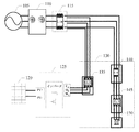
図1は一技術案における新エネルギーをグリッドに接続する配電方式を示す模式図である。図1に示すように、この配電システムは、計量メータ110と、容量限定ブレーカ115と、家庭配電側130と、エネルギー変換モジュール125とを有してもよい。家庭配電側130はリーク保護ブレーカ135と、容量限定ブレーカ140と、リーク保護ブレーカ145と、負荷150とを有してもよい。
FIG. 1 is a schematic diagram showing a power distribution system for connecting new energy to a grid in one technical proposal. As shown in FIG. 1, the distribution system may include a
ここで、計量メータ110は、グリッド105に電気的に接続され、出力グリッド又は入力グリッドの電量を計測するために用いられる。容量限定ブレーカ115は家庭配電側130におけるリーク保護ブレーカ135及び容量限定ブレーカ140に電気的に接続される。エネルギー変換モジュール125は、第1の入力端と第1の出力端とを備え、第1の入力端は太陽光発電装置120に接続され、第1の出力端はリーク保護ブレーカ135に電気的に接続され、発電装置120から出力された電気エネルギーを変換するために用いられる。
Here, the weighing
しかしながら、図1に示す配電システムは、太陽光発電装置120をグリッドに接続して電気を販売する稼動モードしか満足できなく、グリッドに故障がある場合に太陽光発電装置120により負荷に給電できない。
However, the power distribution system shown in FIG. 1 can satisfy only the operation mode in which the photovoltaic
図2は他の技術案における新エネルギーをグリッドに接続する配電方式を示す模式図である。図2における配電システムが図1における配電システムと相違するのは、エネルギー変換モジュール125が、グリッド105に故障がある場合に負荷に給電するためのグリッド切断給電ソケット205をさらに備えることである。グリッド接続稼動の場合に、図2における配電システムの接続方式は図1における配電システムと一致し、ここで詳細な説明を省略する。
FIG. 2 is a schematic diagram showing a power distribution method for connecting new energy to a grid in another technical solution. The power distribution system in FIG. 2 differs from the power distribution system in FIG. 1 in that the
しかしながら、図2に示す配電システムにおいて、グリッド105に故障がある場合、家庭用負荷は、屋外のグリッド切断給電ソケット205によって給電される必要があり、不便であり、且つ、同様に天気等によって給電が不安定になるという問題がある。
However, in the power distribution system shown in FIG. 2, when the
図3は別の技術案における新エネルギーをグリッドに接続する配電方式を示す模式図である。図3における配電システムが図1における配電システムと相違するのは、エネルギー変換モジュール125が第2の出力端をさらに備え、家庭配電側130が優先負荷305をさらに備え、優先負荷305はエネルギー変換モジュール125の第2の出力端に電気的に接続されることである。
FIG. 3 is a schematic diagram showing a power distribution method for connecting new energy to a grid according to another technical proposal. The power distribution system in FIG. 3 differs from the power distribution system in FIG. 1 in that the
図3に示す配電システムは、給電が不安定であるという問題はあるが、グリッドに故障がある場合に重要な負荷が容易に電力を得ることができる。ただし、図3における配電システムは新築住宅に適しており、既に配電装飾を完成した住宅に対しては既存の配電方式を改良する必要があり、高価である。 The power distribution system shown in FIG. 3 has a problem that the power supply is unstable, but an important load can easily obtain power when the grid has a failure. However, the power distribution system in FIG. 3 is suitable for a new house, and for a house whose distribution decoration has already been completed, it is necessary to improve the existing power distribution system, which is expensive.
さらに、発電装置のグリッド切断給電は安全な給電の要求を満足する必要もあり、図4及び図5に示されているのは従来の給電方式である。図4は一技術案におけるTN−S給電システムを示す模式図である。図5は他の技術案におけるTN−C−S給電システムを示す模式図である。 Further, the grid disconnection power supply of the power generator is required to satisfy the requirement of safe power supply, and the conventional power supply system is shown in FIGS. 4 and 5. FIG. 4 is a schematic diagram showing a TN-S power feeding system in one technical solution. FIG. 5 is a schematic diagram showing a TN-C-S power feeding system in another technical solution.
図4に示すように、TN−S給電システムにおいて、作業ニュートラルライン(中性線)Nは専用保護線PEから離間し、給電システムが正常に稼動している場合、専用保護線PEには電流が流れなく、負荷のニュートラルライン接続保護線は専用保護線PEに接続されることによって、給電システムの安全性と信頼性を向上させる。 As shown in FIG. 4, in the TN-S power feeding system, the work neutral line (neutral wire) N is separated from the dedicated protection line PE, and when the power feeding system is operating normally, the dedicated protection line PE is supplied with current. Does not flow and the neutral line connection protection line of the load is connected to the dedicated protection line PE, thereby improving the safety and reliability of the power supply system.
図5に示すように、TN−C−S給電システムにおいて、作業ニュートラルラインNが専用保護線PEに接続されている部分、即ちN線が接地されている部分では、PE線である作業ニュートラルラインNを繰り返して接地する必要があり、そうでなければ電力を安全に供給することは困難になる。 As shown in FIG. 5, in the TN-C-S power feeding system, the working neutral line N is a PE line at a portion where the working neutral line N is connected to the dedicated protection line PE, that is, a portion where the N line is grounded. N must be repeatedly grounded or it will be difficult to safely supply power.
このため、現在の給電システムにおいて、発電装置は負荷端に作業ニュートラルラインNが接地される方式と接地されていない方式との2種類の方式があり、グリッド接続稼動の場合に、単相2線でグリッドと交互にエネルギーを供給できるため、作業ニュートラルラインNを2回接地されることを許可しなく、グリッド切断稼動の場合に、ユーザに対して、元配電案のグリッドからの給電出力と一致する単相3線式電圧源出力を提供し、このため、作業ニュートラルラインNがローカルに接地される必要がある。 Therefore, in the current power supply system, there are two types of power generators, a system in which the work neutral line N is grounded at the load end and a system in which the work neutral line N is not grounded. Since it is possible to supply energy alternately with the grid, the work neutral line N is not allowed to be grounded twice, and in the case of grid cutting operation, it matches the power supply output from the grid of the original power distribution plan to the user. To provide a single-phase three-wire voltage source output, which requires the working neutral line N to be locally grounded.
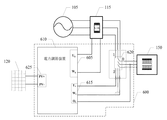
上記の記載に基づき、本開示の1つの例示的な実施例では、まず配電機器を提供する。図6に示すように、この配電機器600は電力調節装置610と第1の補助配電ユニット620とを有してもよい。
Based on the above description, one exemplary embodiment of the present disclosure first provides a power distribution device. As shown in FIG. 6, the
電力調節装置610は第1の出力端605と第2の出力端615とを有し、ここで、第1の出力端605は交流グリッド105に電気的に接続され、第1の補助配電ユニット620は第1の可動端0と第1の固定端1と第2の固定端2とを有し、第1の可動端0は負荷150に電気的に接続され、第1の固定端1は交流グリッド105に電気的に接続され、第2の固定端2は第2の出力端615に電気的に接続され、且つ、第2の固定端2の接地線は接地され、交流グリッド105が正常である場合、第1の可動端0は第1の固定端1に接続され、交流グリッド105は負荷150に電力を供給し、交流グリッド105が異常である場合、第1の可動端0は第2の固定端2に接続され、電力調節装置610は第2の出力端615を介して負荷150に電力を供給する。
The
さらに、例示的な本実施例では、負荷150の中性線は電力調節装置610における第2の出力端615の中性線に電気的に接続され、第1の補助配電ユニット620の第1の可動端0が第2の固定端2に接続される場合、負荷150の中性線と電力調節装置610における第2の出力端615の中性線はともに第2の固定端2の接地線に電気的に接続され、且つ、第2の固定端2の接地線を介して接地される。
Further, in this exemplary embodiment, the neutral wire of the
図6に示す配電機器によれば、交流グリッドが異常である場合、第1の補助配電ユニット620の第1の可動端0は第2の固定端2に接続され、且つこの第2の固定端2の接地線は接地されることによって、グリッド切断稼動の場合、電力調節装置から出力された三相交流が負荷に直接に電力を供給し、且つ負荷及び電力調節装置から出力された三相交流はともに接地されることができ、これにより、負荷150に電力を安全に供給する。一方で、本開示の例示的な実施例における配電機器により、ユーザの元(既存の)配電構造を調整する必要がなく、グリッド切断稼動及びグリッド接続稼動の要求を満足でき、人力及び物力のコストを節約できる。
According to the power distribution device shown in FIG. 6, when the AC grid is abnormal, the first
また、例示的な本実施例では、電力調節装置610が第1の入力端625を有してもよく、第1の入力端625は発電装置120に電気的に接続され、電力調節装置610は発電装置120から出力される電気エネルギーを変換するために用いられることができる。大グリッドが正常に動作する場合、電力調節装置610は発電装置120から出力される電気エネルギーを適切な交流(本開示では、第1の交流と呼ばれる)に変換し、且つ、第1の出力端605を介して大グリッドに供給し、これによりグリッド接続発電が図られる。大グリッドが異常(例えば、グリッド故障による停電)である場合、電力調節装置610は発電装置120から出力される電気エネルギーを適切な交流(本開示でば、第2の交流と呼ばれる)に変換し、且つ、第2の出力端615を介して負荷に供給し、これによりグリッド切断発電が図られる。
Also, in the exemplary embodiment,
なお、例示的な本実施例では、発電装置120は太陽光発電装置であるが、本開示の例示的な実施例はこれに限定されなく、例えば発電装置は風力発電装置又は燃料電池発電装置などであってもよく、本開示では、これを特に限定しない。同様に、電力調節装置610は複数の第1の入力端625をさらに有してもよく、第1の入力端625のそれぞれは対応する1つの発電装置120に接続され、且つ、複数の発電装置120は異なる種類であってもよい。
In addition, in the exemplary embodiment, the
さらに、例示的な本実施例では、第1の入力端625は直流入力端であり、交流グリッド105が正常である場合、電力調節装置610は発電装置120から出力される電気エネルギーを第1の交流に変換し、且つ、第1の出力端605を介して交流グリッド105に伝送し、発電装置120はグリッド接続発電モードで動作し、交流グリッド105が異常である場合、電力調節装置610は発電装置120から出力される電気エネルギーを第2の交流に変換し、且つ、第2の出力端615を介して負荷150に電力を供給し、発電装置120はグリッド切断発電モードで動作する。
Further, in the present exemplary embodiment, the
新エネルギー発電は主に断続的に発電し、給電が不安定である。太陽光発電を例として、グリッドは、夜間などの消費電力のピーク時に太陽光発電を利用できないが、昼間などの給電のアイドル時に大量の太陽光電力を吸収する必要がある。このため、グリッドの給電のアイドル時に新エネルギー発電を吸收して蓄積する必要があり、消費電力のピーク時に蓄積された新エネルギー発電によって給電できる。従って、エネルギー蓄積システムは、新エネルギー発電が不安定であるという問題を解決する焦点となっている。エネルギー蓄積システムの接続はグリッドが新エネルギー発電のピークと消費電力のピークとの時差のマッチングを改善することに寄与する。図7は本発明の他の例示的な実施例による配電機器を示す模式図である。 New energy power generation mainly generates power intermittently, and power supply is unstable. Taking solar power generation as an example, the grid cannot utilize solar power during peak power consumption, such as at night, but needs to absorb a large amount of solar power during idle power feeds, such as during the day. Therefore, it is necessary to absorb and store the new energy power generation when the grid power supply is idle, and the power can be fed by the new energy power generation accumulated at the peak of power consumption. Therefore, energy storage systems have been the focus of solving the problem of unstable new energy generation. The connection of the energy storage system helps the grid improve the time difference matching between the new energy generation peak and the power consumption peak. FIG. 7 is a schematic view showing a power distribution device according to another exemplary embodiment of the present invention.
図7に示すように、この配電機器700は電力調節装置710と第1の補助配電ユニット720とを有してもよい。発電装置120は直流側から配電機器700に接続される。
As shown in FIG. 7, the
例示的な本実施例では、電力調節装置710は第1の出力端705と、第2の出力端715と、第1の入力端725と、第2の入力端740とを有し、ここで、第1の出力端705は交流グリッド105に電気的に接続され、第1の入力端725は発電装置120に電気的に接続され、第2の入力端740はエネルギー蓄積装置745に電気的に接続される。
In the exemplary embodiment,
さらに、電力調節装置710は、発電装置120又はエネルギー蓄積装置745の電気エネルギーを変換するための電力変換回路735をさらに有してもよい。
Further, the
第1の補助配電ユニット720は第1の可動端0と、第1の固定端1と、第2の固定端2とを有し、第1の可動端0は負荷150に電気的に接続され、第1の固定端1は交流グリッド105に電気的に接続され、第2の固定端2は第2の出力端715に電気的に接続され、且つ、第2の固定端2の接地線は接地され、交流グリッド105が正常である場合、第1の可動端0は第1の固定端1に接続され、交流グリッド105は負荷150に電力を供給し、交流グリッド105が異常である場合、第1の可動端0は第2の固定端2に接続され、電力調節装置710は第2の出力端715を介して負荷150に電力を供給する。
The first auxiliary
さらに、例示的な本実施例では、負荷150の中性線は電力調節装置710における第2の出力端715の中性線に電気的に接続され、第1の補助配電ユニット720の第1の可動端0が第2の固定端2に接続される場合、負荷150の中性線と電力調節装置710における第2の出力端715の中性線はともに第2の固定端2の接地線に電気的に接続され、且つ、第2の固定端2の接地線を介して接地される。
Further, in this exemplary embodiment, the neutral wire of the
さらに、交流グリッド105が正常である場合、電力調節装置710はエネルギー蓄積装置745の電気エネルギーを第1の交流に変換し、且つ、第1の出力端705を介して交流グリッド105に伝送し、交流グリッド105が異常である場合、電力調節装置710はエネルギー蓄積装置745の電気エネルギーを第2の交流に変換し、且つ、第2の出力端715を介して負荷150に電力を供給する。
Further, when the
例示的な本実施例では、電力変換回路735はエネルギー蓄積装置から出力される電気エネルギーを変換してもよく、入力された電気エネルギーを変換してエネルギー蓄積装置に蓄積してもよい。エネルギー蓄積装置の接続のため、交流グリッド105に故障がある場合、負荷150に安定な電力を供給でき、発電装置120は、グリッド切断の場合に、負荷150に電力を供給したり、エネルギー蓄積システムを充電したりできる。発電装置120は、グリッドに故障がある場合に負荷に電力を供給したり、消費電力のピーク時にグリッドに電気エネルギーを伝送したりできるように、グリッド接続の場合に余分な電気エネルギー(例えば、給電のアイドル時に)をエネルギー蓄積システムに蓄積することができる。
In the present exemplary embodiment, the power conversion circuit 735 may convert electric energy output from the energy storage device or may convert input electric energy to be stored in the energy storage device. Due to the connection of the energy storage device, when the
なお、例示的な本実施例では、交流グリッド105が異常である場合、発電装置120及びエネルギー蓄積装置745の少なくとも1つは電力変換回路735と第2の出力端715を介して負荷150に電力を供給することができる。
Note that in the present exemplary embodiment, when the
なお、図7に示す電力調節装置710はエネルギー蓄積装置745を有しないが、本開示の例示的な実施例では、電力調節装置710はエネルギー蓄積装置745をさらに有してもよく、同様に本開示の保護範囲にある。同様に、電力調節装置710は複数の第2の入力端740をさらに有してもよく、且つ、第2の入力端740のそれぞれが対応する1つのエネルギー蓄積装置745に接続される。
It should be noted that while the
図8は本発明の別の例示的な実施例による配電機器を示す模式図である。 FIG. 8 is a schematic diagram showing a power distribution device according to another exemplary embodiment of the present invention.
図8に示すように、この配電機器800は、電力調節装置810と、第1の補助配電ユニット820と、第2の補助配電ユニット840とを有してもよい。発電装置120は交流側から配電機器800に接続される。
As shown in FIG. 8, the
例示的な本実施例では、電力調節装置810は第1の出力端805と、第2の出力端815と、第1の入力端825と、第2の入力端870とを有し、ここで、第1の出力端805は交流グリッド105に電気的に接続され、第1の入力端825は発電装置120に電気的に接続され、第2の入力端870はエネルギー蓄積装置845に電気的に接続される。
In the exemplary embodiment,
例示的な本実施例では、第1の補助配電ユニット820は第1の可動端01と、第1の固定端1と、第2の固定端2とを有し、第1の可動端01は負荷150に電気的に接続され、第1の固定端1は交流グリッド105に電気的に接続され、第2の固定端2は第2の出力端815に電気的に接続され、且つ、第2の固定端2の接地線は接地され、交流グリッド105が正常である場合、第1の可動端01は第1の固定端1に接続され、交流グリッド105は負荷150に電力を供給し、交流グリッド105が異常である場合、第1の可動端01は第2の固定端2に接続され、電力調節装置810は第2の出力端815を介して負荷150に電力を供給する。
In the present exemplary embodiment, the first auxiliary
なお、例示的な本実施例では、第2の補助配電ユニット840は第2の可動端02と、第3の固定端3と、第4の固定端4とを有し、第2の可動端02は発電装置120に電気的に接続され、第3の固定端3は第1の入力端825に電気的に接続され、第4の固定端4は交流グリッド105に電気的に接続され、且つ、第3の固定端3の接地線は接地される。
In the exemplary embodiment, the second auxiliary
さらに、例示的な本実施例では、第1の入力端825は交流入力端であり、交流グリッド105が正常である場合、第2の可動端02は第4の固定端4に接続され、発電装置120は第2の補助配電ユニット840を介して電気エネルギーを交流グリッド105に出力し、発電装置120はグリッド接続発電モードで動作し、交流グリッド105が異常である場合、第2の可動端02は第3の固定端3に接続され、発電装置120は第2の補助配電ユニット840を介して電気エネルギーを第1の入力端825に出力し、発電装置120はグリッド切断発電モードで動作する。
Further, in the present exemplary embodiment, the
なお、例示的な本実施例では、電力調節装置810は発電装置120又はエネルギー蓄積装置845の電気エネルギーを変換するための電力変換回路835をさらに有してもよい。交流グリッド105が異常である場合、発電装置120及び/又はエネルギー蓄積装置845は電力変換回路835及び第2の出力端815を介して負荷150に電力を供給する。交流グリッド105が異常である場合、発電装置120から出力される交流は第2の補助配電ユニット840を介して電力変換装置810における第1の入力端825に伝送され、ここで、第2の可動端02が第3の固定端3に接続されると、発電装置120における出力端121の中性線は第3の固定端3の接地線に接続され、即ち、発電装置120における出力端121は第3の固定端3によって接地される。電力変換回路は発電装置120により提供される電気エネルギーを適切な交流(本開示では、第2の交流と呼ばれる)に変換し、且つ、第1の補助配電ユニット820及び第2の出力端815を介して負荷150に供給して負荷150に電力を供給する。発電装置120が発電のピーク時にある場合、余分な電気エネルギーが電力変換回路835を介して変換されて、第2の入力端870を介してエネルギー蓄積装置845を充電でき、発電装置120が発電のアイドル時にある場合、不十分な電気エネルギーはエネルギー蓄積装置845により提供されてもよく、即ち、エネルギー蓄積装置845と発電装置120とは共通に負荷150に電力を供給する。ここで、第1の可動端01は第2の固定端2に接続され、負荷150の中性線は第2の出力端815の中性線に電気的に接続され、且つ、第2の固定端2の接地線に接続され、これにより、安全性の要求を満足する。
It should be noted that in the present exemplary embodiment, the
交流グリッド105が正常である場合、発電装置120は電気エネルギーを交流グリッド105に出力し、グリッド接続モードで動作する。消費電力のピーク時にある場合、エネルギー蓄積装置845は電力変換回路835及び第1の出力端805を介して電気エネルギーを交流グリッド105に出力できる。消費電力のアイドル時にある場合、交流グリッド105は第1の出力端805及び電力変換回路835を介してエネルギー蓄積装置を充電できる。
When the
なお、本開示の例示的な実施例では、第1の補助配電ユニットと第2の補助配電ユニットとは3方向スイッチであってもよく、他の好適なユニットであってもよく、本開示はこれを特に限定しない。補助配電ユニットは手動切替方式を採用してもよく、スマート切替方式を採用してもよい。手動切替方式を採用すると、電力調節装置におけるマスタ制御システムがグリッドの故障を検出した場合、取得しやすい方式によりユーザに通知し、例えば警報を発信したり、故障情報を製品の視覚インタフェースに表示したり、故障情報をアプリケーションソフトウェア(例えば、携帯電話APPなど)へ送信したりして、ユーザが故障情報を取得してから、手動で補助配電ユニットを切り替え、これにより発電装置及び/又はエネルギー蓄積装置を採用して負荷に電力を供給する。スマート切替方式を採用すると、各補助配電ユニットにはコントローラが集積され、電力調節装置におけるマスタ制御システムがグリッドの故障を検出した場合、コントローラと通信を行い、故障情報をコントローラに伝達し、コントローラは補助配電ユニットが切り替えを行うように制御し、これにより発電装置及び/又はエネルギー蓄積装置を採用して負荷に電力を供給する。 It should be noted that in the exemplary embodiment of the present disclosure, the first auxiliary power distribution unit and the second auxiliary power distribution unit may be three-way switches or other suitable units. This is not particularly limited. The auxiliary power distribution unit may employ a manual switching system or a smart switching system. When the manual switching method is adopted, when the master control system in the power regulator detects a grid failure, it notifies the user by a method that is easy to obtain, for example, issues an alarm or displays the failure information on the visual interface of the product. Alternatively, the failure information is transmitted to application software (for example, mobile phone APP, etc.), and after the user obtains the failure information, the auxiliary power distribution unit is manually switched, whereby the power generation device and/or the energy storage device. To supply power to the load. When the smart switching method is adopted, a controller is integrated in each auxiliary power distribution unit, and when the master control system in the power adjustment device detects a grid failure, it communicates with the controller and transmits failure information to the controller, which then The auxiliary power distribution unit controls the switching so that the power generator and/or the energy storage device is employed to supply power to the load.
さらに、本開示の例示的な実施例における配電機器は家庭用配電に適用でき、家庭用配電に適用する場合、第1の補助配電ユニット及び/又は第2の補助配電ユニットは家庭用負荷のメインスイッチの前に設けられてもよい。 Further, the power distribution device in the exemplary embodiment of the present disclosure can be applied to household power distribution, and when applied to household power distribution, the first auxiliary power distribution unit and/or the second auxiliary power distribution unit can be a main load of a household load. It may be provided before the switch.
なお、本開示の例示的な実施例では、上記の図6及び図7に示す配電機器に適用可能な配電方法をさらに提供する。この配電方法は、前記交流グリッドが正常である場合、前記交流グリッドが前記負荷に電力を供給するように、前記第1の補助配電ユニットの前記第1の可動端は前記第1の固定端に接続されるステップと、前記交流グリッドが異常である場合、前記電力調節装置が前記第2の出力端を介して前記負荷に電力を供給するように、前記第1の補助配電ユニットの前記第1の可動端は前記第2の固定端に接続されるステップと、含むことができる。 It should be noted that the exemplary embodiment of the present disclosure further provides a power distribution method applicable to the power distribution devices shown in FIGS. 6 and 7 above. In the power distribution method, when the AC grid is normal, the first movable end of the first auxiliary power distribution unit is connected to the first fixed end so that the AC grid supplies power to the load. Connecting, and if the AC grid is abnormal, the first of the first auxiliary power distribution unit so that the power conditioner supplies power to the load via the second output. A movable end of the second fixed end may be connected to the second fixed end.
なお、本開示の例示的な実施例では、上記の図8に示す配電機器に適用可能な他の配電方法をさらに提供する。この配電方法は、前記交流グリッドが正常である場合、前記交流グリッドが前記負荷に電力を供給するように、前記第1の補助配電ユニットの前記第1の可動端は前記第1の固定端に接続され、且つ、前記発電装置が電気エネルギーを前記交流グリッドに出力するように、前記第2の補助配電ユニットの前記第2の可動端は前記第4の固定端に接続されるステップと、前記交流グリッドが異常である場合、前記電力調節装置が前記第2の出力端を介して前記負荷に電力を供給するように、前記第1の補助配電ユニットの前記第1の可動端は前記第2の固定端に接続され、且つ、前記発電装置が電気エネルギーを前記電力調節装置に出力するように、前記第2の補助配電ユニットの前記第2の可動端は前記第3の固定端に接続されるステップと、含むことができる。 Note that the exemplary embodiment of the present disclosure further provides another power distribution method applicable to the power distribution device shown in FIG. 8 described above. In the power distribution method, when the AC grid is normal, the first movable end of the first auxiliary power distribution unit is connected to the first fixed end so that the AC grid supplies power to the load. Said second movable end of said second auxiliary power distribution unit being connected to said fourth fixed end so that said power generator outputs electrical energy to said alternating current grid. If the alternating current grid is abnormal, the first movable end of the first auxiliary power distribution unit may be connected to the second movable end of the first auxiliary power distribution unit so that the power adjusting device supplies electric power to the load via the second output end. The second movable end of the second auxiliary power distribution unit is connected to the third fixed end so that the power generation device outputs electric energy to the power adjustment device. Can be included.
本開示は、実際のニーズに応じて、新エネルギー投入モードや負荷給電モードを柔軟に切り替える。システムがグリッドが正常であることを検出した場合、自動又は手動でグリッド接続稼動モードに切り替わって、負荷がグリッド及び発電装置によって直接給電され、負荷に給電するためのN線はグリッドN線であり、負荷側は2回接地されない。システムがグリッドの故障を検出した場合、自動又は手動でグリッド切断稼動モードに切り替わって、電力調節装置が発電装置及び/又はエネルギー蓄積装置の電気エネルギーを利用して負荷に電力を供給し、同時に負荷N線と給電機器N線とが接地の要求を満足する。 The present disclosure flexibly switches between the new energy input mode and the load power supply mode according to actual needs. When the system detects that the grid is normal, it automatically or manually switches to the grid connection operation mode, the load is directly supplied by the grid and the generator, and the N line for supplying the load is the grid N line. , The load side is not grounded twice. When the system detects a grid failure, it automatically or manually switches to the grid disconnection operating mode, and the power regulator uses the electrical energy of the generator and/or energy storage device to power the load and at the same time load the load. The N line and the power feeding device N line satisfy the grounding requirement.
本発明に係る配電機器は、安全な給電を実現できるばかりでなく、既存の配電線路を変えずに様々な配電方式を実現することもできる。例えば、グリッドが正常である場合に実現可能な配電方式は、グリッドが負荷に電力を供給する方式と、グリッドと新エネルギーとが同時に負荷に電力を供給する方式と、グリッド、新エネルギー及びエネルギー蓄積装置が共通に負荷に電力を供給する方式と、を含む。グリッドが異常である場合に実現可能な配電方式は、新エネルギーが負荷に電力を供給する方式と、新エネルギーとエネルギー蓄積装置とが共通に負荷に電力を供給する方式と、を含む。補助配電ユニットの端子の接続方式を変えることだけでも、上記の様々な配電方式の間で柔軟に切り替わることができ、非常に便利である。 The power distribution device according to the present invention can realize not only safe power feeding but also various power distribution methods without changing existing power distribution lines. For example, power distribution methods that can be realized when the grid is normal include a method in which the grid supplies power to the load, a method in which the grid and new energy simultaneously supply power to the load, and the grid, new energy, and energy storage. The devices commonly supply power to the load. Power distribution methods that can be implemented when the grid is abnormal include a method in which new energy supplies power to the load and a method in which new energy and the energy storage device commonly supply power to the load. It is very convenient because it is possible to flexibly switch between the above various power distribution systems by simply changing the connection system of the terminals of the auxiliary power distribution unit.
本発明に係る配電機器に補助配電ユニットを追加することで、グリッド切断稼動の場合、補助配電ユニットによってN線が負荷のローカルに接地されることが図られ、グリッド接続の場合の発電モードを模擬し、異なるユーザのニーズに合わせて製品を別々に開発する必要がなくなり、発電機器が接続される配電方式を調整するだけでも安全な給電及び異なる動作モードを実現できる。補助配電ユニットが負荷のメインスイッチの前に設けられるため、配電線路に補助配電ユニットを容易に追加及び除去でき、既存の配電線路に影響を与えない。本発明に係る配電機器及び配電方法は、ユーザの既存の配電を再構築する必要がなく、異なるユーザ及び安全な給電の要求を満足できる。 By adding the auxiliary power distribution unit to the power distribution device according to the present invention, the N line can be grounded locally to the load by the auxiliary power distribution unit in the grid disconnection operation, and the power generation mode in the grid connection is simulated. However, it is not necessary to separately develop products according to the needs of different users, and it is possible to realize safe power supply and different operation modes simply by adjusting the power distribution system to which the power generation device is connected. Since the auxiliary power distribution unit is provided in front of the main switch of the load, the auxiliary power distribution unit can be easily added to and removed from the power distribution line without affecting the existing power distribution line. INDUSTRIAL APPLICABILITY The power distribution device and the power distribution method according to the present invention do not need to rebuild existing power distribution of users, and can satisfy different users and demands for safe power supply.
当業者は、明細書に対する理解、及び明細書に記載された発明に対する実施を介して、本発明の他の実施例を容易に取得することができる。本発明は、本発明に対する任意の変形、応用、又は適応的な変化を含み、このような変形、応用、又は適応的な変化は、本発明の一般的な原理に従い、本発明では開示していない本技術分野の公知技術、又は通常の技術手段を含む。明細書及び実施例は、単に例示的なものであって、本発明の本当の範囲と主旨は、以下の特許請求の範囲によって示される。 Those skilled in the art can easily obtain other embodiments of the present invention through understanding of the specification and practice of the invention described in the specification. The present invention includes any modification, application, or adaptive change to the present invention, and such modification, application, or adaptive change is disclosed in the present invention in accordance with the general principle of the present invention. It does not include a known technique in this technical field, or an ordinary technical means. The specification and examples are merely illustrative and the true scope and spirit of the invention is indicated by the following claims.
本開示は、上記で記述され、図面で図示した特定の構成に限定されず、その範囲を離脱しない状況で、様々な修正や変更を実施してもよい。本発明の範囲は、添付される特許請求の範囲のみにより限定される。 The present disclosure is not limited to the particular configurations described above and illustrated in the drawings, and various modifications and changes may be made without departing from the scope thereof. The scope of the invention is limited only by the appended claims.
Claims (11)
第1の可動端と第1の固定端と第2の固定端とを有し、前記第1の可動端が負荷に電気的に接続され、前記第1の固定端が前記交流グリッドに電気的に接続され、前記第2の固定端が前記第2の出力端に電気的に接続され、且つ、前記第2の固定端の接地線が接地される第1の補助配電ユニットとを備え、
ここで、前記交流グリッドが正常である場合、前記第1の可動端は前記第1の固定端に接続され、前記交流グリッドは前記負荷に電力を供給し、前記交流グリッドが異常である場合、前記第1の可動端は前記第2の固定端に接続され、前記電力調節装置は前記第2の出力端を介して前記負荷に電力を供給し、
前記負荷の中性線が前記第2の出力端の中性線に電気的に接続され、前記第1の可動端が前記第2の固定端に接続される場合、前記負荷の中性線と前記第2の出力端の中性線とは前記第2の固定端の接地線に電気的に接続され、且つ、前記第2の固定端の接地線を介して接地されることを特徴とする配電機器。 A power conditioner having a first output end and a second output end, the first output end electrically connected to an AC grid;
A first movable end, a first fixed end, and a second fixed end, the first movable end is electrically connected to a load, and the first fixed end is electrically connected to the AC grid. A second auxiliary end electrically connected to the second output end, and a ground wire of the second fixed end is grounded,
Here, when the alternating current grid is normal, the first movable end is connected to the first fixed end, the alternating current grid supplies power to the load, and when the alternating current grid is abnormal, The first movable end is connected to the second fixed end, the power adjusting device supplies electric power to the load via the second output end ,
When the neutral wire of the load is electrically connected to the neutral wire of the second output end and the first movable end is connected to the second fixed end, the neutral wire of the load is The neutral wire of the second output end is electrically connected to the ground wire of the second fixed end, and is grounded via the ground wire of the second fixed end. Power distribution equipment.
前記交流グリッドが正常である場合、前記交流グリッドが前記負荷に電力を供給するように、前記第1の補助配電ユニットの前記第1の可動端は前記第1の固定端に接続されるステップと、
前記交流グリッドが異常である場合、前記電力調節装置が前記第2の出力端を介して前記負荷に電力を供給するように、前記第1の補助配電ユニットの前記第1の可動端は前記第2の固定端に接続されるステップと、
前記負荷の中性線が前記第2の出力端の中性線に電気的に接続され、前記第1の可動端が前記第2の固定端に接続される場合、前記負荷の中性線と前記第2の出力端の中性線とは前記第2の固定端の接地線に電気的に接続され、且つ、前記第2の固定端の接地線を介して接地されるステップと、を含むことを特徴とする配電方法。 A power distribution method applied to the power distribution device according to any one of claims 1 to 5 ,
Connecting the first movable end of the first auxiliary power distribution unit to the first fixed end so that the alternating current grid supplies power to the load when the alternating current grid is normal; ,
If the alternating current grid is abnormal, the first movable end of the first auxiliary power distribution unit is configured to supply the electric power to the load via the second output end. A step connected to the fixed end of 2,
When the neutral wire of the load is electrically connected to the neutral wire of the second output end and the first movable end is connected to the second fixed end, the neutral wire of the load is A step of electrically connecting the neutral wire of the second output terminal to the ground wire of the second fixed terminal, and grounding via the ground wire of the second fixed terminal. A power distribution method characterized by the above.
前記交流グリッドが正常である場合、前記交流グリッドが前記負荷に電力を供給するように、前記第1の補助配電ユニットの前記第1の可動端は前記第1の固定端に接続され、且つ、前記発電装置が電気エネルギーを前記交流グリッドに出力するように、前記第2の補助配電ユニットの前記第2の可動端は前記第4の固定端に接続されるステップと、
前記交流グリッドが異常である場合、前記電力調節装置が前記第2の出力端を介して前記負荷に電力を供給するように、前記第1の補助配電ユニットの前記第1の可動端は前記第2の固定端に接続され、且つ、前記発電装置が電気エネルギーを前記電力調節装置に出力するように、前記第2の補助配電ユニットの前記第2の可動端は前記第3の固定端に接続されるステップと、含むことを特徴とする配電方法。 A power distribution method applied to the power distribution device according to any one of claims 6 to 8 ,
When the AC grid is normal, the first movable end of the first auxiliary power distribution unit is connected to the first fixed end so that the AC grid supplies power to the load, and Connecting the second movable end of the second auxiliary power distribution unit to the fourth fixed end so that the power generator outputs electrical energy to the AC grid;
If the alternating current grid is abnormal, the first movable end of the first auxiliary power distribution unit may be configured to supply the power to the load via the second output end. The second movable end of the second auxiliary power distribution unit is connected to the third fixed end so that the power generation device outputs electric energy to the power adjustment device. And a power distribution method including the following steps.
Applications Claiming Priority (2)
| Application Number | Priority Date | Filing Date | Title |
|---|---|---|---|
| CN201810062799.5A CN110071521B (en) | 2018-01-23 | 2018-01-23 | Power distribution equipment and power distribution method |
| CN201810062799.5 | 2018-01-23 |
Publications (2)
| Publication Number | Publication Date |
|---|---|
| JP2019129700A JP2019129700A (en) | 2019-08-01 |
| JP6719604B2 true JP6719604B2 (en) | 2020-07-08 |
Family
ID=67300296
Family Applications (1)
| Application Number | Title | Priority Date | Filing Date |
|---|---|---|---|
| JP2019004009A Active JP6719604B2 (en) | 2018-01-23 | 2019-01-15 | Power distribution equipment and power distribution method |
Country Status (3)
| Country | Link |
|---|---|
| US (1) | US10992168B2 (en) |
| JP (1) | JP6719604B2 (en) |
| CN (1) | CN110071521B (en) |
Family Cites Families (29)
| Publication number | Priority date | Publication date | Assignee | Title |
|---|---|---|---|---|
| US6111767A (en) * | 1998-06-22 | 2000-08-29 | Heliotronics, Inc. | Inverter integrated instrumentation having a current-voltage curve tracer |
| US7042376B1 (en) * | 2005-05-20 | 2006-05-09 | National Instruments Corporation | Scanning front end using single-pole, double-throw switches to reduce settling time |
| US8148851B2 (en) * | 2009-05-27 | 2012-04-03 | Litecontrol Corporation | Simplified lighting control system |
| US8896157B2 (en) * | 2009-11-24 | 2014-11-25 | Delta Electronics, Inc. | Power supply and power supplying system with remote power management function |
| CN102214994A (en) * | 2010-04-07 | 2011-10-12 | 上海航锐电源科技有限公司 | Input-series and output-series boost converter, voltage-equalizing and current-equalizing control circuit and voltage-equalizing and current-equalizing control method |
| EP2485356A1 (en) | 2011-02-02 | 2012-08-08 | Arista Power, Inc. | Energy storage and power management system |
| US9583942B2 (en) * | 2011-04-20 | 2017-02-28 | Reliance Controls Corporation | Transfer switch for automatically switching between alternative energy source and utility grid |
| US8937822B2 (en) * | 2011-05-08 | 2015-01-20 | Paul Wilkinson Dent | Solar energy conversion and utilization system |
| CN202405863U (en) * | 2011-12-30 | 2012-08-29 | 上海追日电气有限公司 | Hybrid inverter |
| US9337690B2 (en) * | 2012-10-26 | 2016-05-10 | Eaton Corporation | UPS systems and methods using mode-dependent grounding |
| US9711967B1 (en) * | 2012-11-06 | 2017-07-18 | Reliance Conrtols Corporation | Off grid backup inverter automatic transfer switch |
| CN103825474B (en) * | 2012-11-16 | 2016-08-31 | 台达电子工业股份有限公司 | The electric power conversion apparatus of low common-mode noise and application system thereof |
| JP6095407B2 (en) | 2013-02-20 | 2017-03-15 | 三菱電機株式会社 | Power supply system |
| JP6174410B2 (en) | 2013-07-29 | 2017-08-02 | 京セラ株式会社 | Power control apparatus, power control method, and power control system |
| CN103457514B (en) | 2013-08-31 | 2015-05-20 | 深圳先进储能材料国家工程研究中心有限公司 | Dual-mode solar photovoltaic power generation system |
| US9774190B2 (en) * | 2013-09-09 | 2017-09-26 | Inertech Ip Llc | Multi-level medium voltage data center static synchronous compensator (DCSTATCOM) for active and reactive power control of data centers connected with grid energy storage and smart green distributed energy sources |
| CN103812115A (en) * | 2014-02-26 | 2014-05-21 | 上海交通大学 | Feedforward voltage series compensation device based on wind-solar-electricity complementation |
| CN104901410A (en) * | 2014-03-04 | 2015-09-09 | 伊顿公司 | UPS circuit |
| DE102014104216B3 (en) * | 2014-03-26 | 2015-06-11 | Sma Solar Technology Ag | Single-phase emergency operation of a three-phase inverter and corresponding inverter |
| CN104505849B (en) | 2015-01-05 | 2017-06-06 | 国家电网公司 | Access way and its method for operation of the energy storage device in 0.4KV distribution net sides |
| CN106160176A (en) * | 2015-04-28 | 2016-11-23 | 台达电子企业管理(上海)有限公司 | Distribution system and electrical system |
| CN106159992B (en) * | 2015-04-28 | 2019-02-12 | 台达电子企业管理(上海)有限公司 | Electric power supply system and power-converting device |
| EP3142222B1 (en) * | 2015-09-11 | 2018-08-01 | ABB Schweiz AG | Uninterrupted power supply with switchable reference |
| WO2017073079A1 (en) | 2015-10-28 | 2017-05-04 | 京セラ株式会社 | Power control device, control method for power control device, power control system and control method for power control system |
| WO2017076687A1 (en) * | 2015-11-05 | 2017-05-11 | Philips Lighting Holding B.V. | A driving circuit driving arrangement and driving method, suitable for grid feeding |
| CN105720602B (en) * | 2016-01-21 | 2019-02-05 | 易事特集团股份有限公司 | Parallel network power generation energy storage inverter is grid-connected-off-grid system and its running gear |
| US20170236648A1 (en) * | 2016-02-12 | 2017-08-17 | Capacitor Sciences Incorporated | Grid capacitive power storage system |
| CA3052242A1 (en) * | 2016-02-12 | 2017-08-17 | Capacitor Sciences Incorporated | Capacitive energy storage cell, capacitive energy storage module, and capacitive energy storage system |
| JP6620937B2 (en) * | 2016-03-31 | 2019-12-18 | パナソニックIpマネジメント株式会社 | Power storage system, operation method |
-
2018
- 2018-01-23 CN CN201810062799.5A patent/CN110071521B/en active Active
-
2019
- 2019-01-09 US US16/243,371 patent/US10992168B2/en active Active
- 2019-01-15 JP JP2019004009A patent/JP6719604B2/en active Active
Also Published As
| Publication number | Publication date |
|---|---|
| US10992168B2 (en) | 2021-04-27 |
| US20190229551A1 (en) | 2019-07-25 |
| JP2019129700A (en) | 2019-08-01 |
| CN110071521A (en) | 2019-07-30 |
| CN110071521B (en) | 2021-09-03 |
Similar Documents
| Publication | Publication Date | Title |
|---|---|---|
| CN103178553B (en) | A kind of family expenses mixed power supply system | |
| TWI565175B (en) | Electricity distribution system and electrical system | |
| US20120126623A1 (en) | Portal for harvesting energy from distributed electrical power sources | |
| US9772347B2 (en) | Interconnection meter socket adapters | |
| US9711967B1 (en) | Off grid backup inverter automatic transfer switch | |
| US11241975B2 (en) | Electric vehicle home microgrid power system | |
| JP2013123355A (en) | Power management apparatus and method of controlling the same | |
| US11415598B2 (en) | Methods and systems for connecting and metering distributed energy resource devices | |
| CN103733465A (en) | Charging device | |
| CN103296696B (en) | Inverter and control method thereof | |
| US10284115B2 (en) | Inverter system | |
| CN203491708U (en) | AC-DC intelligent allocating energy-storage current commutation apparatus | |
| US10523117B2 (en) | Dead band direct current converter | |
| CN104052084A (en) | 110 kilovolt substation micro-grid system used for large electricity consumption places | |
| US20220166219A1 (en) | Systems and methods for modular power conversion units in power supply systems | |
| JP6719604B2 (en) | Power distribution equipment and power distribution method | |
| CN202586401U (en) | Mixing DC system shared by hydropower station and photovoltaic power station | |
| CN112491089A (en) | Micro-grid on-grid and off-grid hybrid switching system and method | |
| TW201403989A (en) | Cable system with phase switch apparatuses | |
| CN204046192U (en) | For the 110 kv substation micro-grid systems in large-scale electricity consumption place | |
| CN210429002U (en) | Real device of instructing of distributing type scene storage power supply system | |
| KR102281206B1 (en) | Electricity supply device for blackout electric consumer and method thereof | |
| CN211579928U (en) | Multifunctional plug-and-play device for household photovoltaic | |
| CN209748263U (en) | Intelligent safe standby power supply system | |
| CN207442517U (en) | Multiple output DC conversion equipment |
Legal Events
| Date | Code | Title | Description |
|---|---|---|---|
| A621 | Written request for application examination |
Free format text: JAPANESE INTERMEDIATE CODE: A621 Effective date: 20190115 |
|
| A977 | Report on retrieval |
Free format text: JAPANESE INTERMEDIATE CODE: A971007 Effective date: 20200207 |
|
| A131 | Notification of reasons for refusal |
Free format text: JAPANESE INTERMEDIATE CODE: A131 Effective date: 20200218 |
|
| A521 | Request for written amendment filed |
Free format text: JAPANESE INTERMEDIATE CODE: A523 Effective date: 20200514 |
|
| TRDD | Decision of grant or rejection written | ||
| A01 | Written decision to grant a patent or to grant a registration (utility model) |
Free format text: JAPANESE INTERMEDIATE CODE: A01 Effective date: 20200526 |
|
| A61 | First payment of annual fees (during grant procedure) |
Free format text: JAPANESE INTERMEDIATE CODE: A61 Effective date: 20200616 |
|
| R150 | Certificate of patent or registration of utility model |
Ref document number: 6719604 Country of ref document: JP Free format text: JAPANESE INTERMEDIATE CODE: R150 |
|
| R250 | Receipt of annual fees |
Free format text: JAPANESE INTERMEDIATE CODE: R250 |