JP6637552B2 - Device for charging energy storage - Google Patents
Device for charging energy storage Download PDFInfo
- Publication number
- JP6637552B2 JP6637552B2 JP2018135450A JP2018135450A JP6637552B2 JP 6637552 B2 JP6637552 B2 JP 6637552B2 JP 2018135450 A JP2018135450 A JP 2018135450A JP 2018135450 A JP2018135450 A JP 2018135450A JP 6637552 B2 JP6637552 B2 JP 6637552B2
- Authority
- JP
- Japan
- Prior art keywords
- transducer
- charging
- circuit
- terminal
- switch
- Prior art date
- Legal status (The legal status is an assumption and is not a legal conclusion. Google has not performed a legal analysis and makes no representation as to the accuracy of the status listed.)
- Active
Links
- 238000004146 energy storage Methods 0.000 title claims description 23
- 238000004804 winding Methods 0.000 claims description 7
- 238000012545 processing Methods 0.000 claims description 3
- 239000004065 semiconductor Substances 0.000 description 16
- 238000010586 diagram Methods 0.000 description 14
- 238000000034 method Methods 0.000 description 13
- 239000003990 capacitor Substances 0.000 description 12
- 230000007935 neutral effect Effects 0.000 description 5
- 230000006978 adaptation Effects 0.000 description 4
- 238000006243 chemical reaction Methods 0.000 description 3
- 238000012546 transfer Methods 0.000 description 3
- 230000002457 bidirectional effect Effects 0.000 description 2
- 239000004020 conductor Substances 0.000 description 2
- 230000001419 dependent effect Effects 0.000 description 2
- 239000002131 composite material Substances 0.000 description 1
- 238000011982 device technology Methods 0.000 description 1
- 230000009977 dual effect Effects 0.000 description 1
- 238000012986 modification Methods 0.000 description 1
- 230000004048 modification Effects 0.000 description 1
- 238000012544 monitoring process Methods 0.000 description 1
- 239000007787 solid Substances 0.000 description 1
Images


Classifications
-
- B—PERFORMING OPERATIONS; TRANSPORTING
- B60—VEHICLES IN GENERAL
- B60L—PROPULSION OF ELECTRICALLY-PROPELLED VEHICLES; SUPPLYING ELECTRIC POWER FOR AUXILIARY EQUIPMENT OF ELECTRICALLY-PROPELLED VEHICLES; ELECTRODYNAMIC BRAKE SYSTEMS FOR VEHICLES IN GENERAL; MAGNETIC SUSPENSION OR LEVITATION FOR VEHICLES; MONITORING OPERATING VARIABLES OF ELECTRICALLY-PROPELLED VEHICLES; ELECTRIC SAFETY DEVICES FOR ELECTRICALLY-PROPELLED VEHICLES
- B60L53/00—Methods of charging batteries, specially adapted for electric vehicles; Charging stations or on-board charging equipment therefor; Exchange of energy storage elements in electric vehicles
- B60L53/10—Methods of charging batteries, specially adapted for electric vehicles; Charging stations or on-board charging equipment therefor; Exchange of energy storage elements in electric vehicles characterised by the energy transfer between the charging station and the vehicle
- B60L53/11—DC charging controlled by the charging station, e.g. mode 4
-
- B—PERFORMING OPERATIONS; TRANSPORTING
- B60—VEHICLES IN GENERAL
- B60L—PROPULSION OF ELECTRICALLY-PROPELLED VEHICLES; SUPPLYING ELECTRIC POWER FOR AUXILIARY EQUIPMENT OF ELECTRICALLY-PROPELLED VEHICLES; ELECTRODYNAMIC BRAKE SYSTEMS FOR VEHICLES IN GENERAL; MAGNETIC SUSPENSION OR LEVITATION FOR VEHICLES; MONITORING OPERATING VARIABLES OF ELECTRICALLY-PROPELLED VEHICLES; ELECTRIC SAFETY DEVICES FOR ELECTRICALLY-PROPELLED VEHICLES
- B60L53/00—Methods of charging batteries, specially adapted for electric vehicles; Charging stations or on-board charging equipment therefor; Exchange of energy storage elements in electric vehicles
- B60L53/10—Methods of charging batteries, specially adapted for electric vehicles; Charging stations or on-board charging equipment therefor; Exchange of energy storage elements in electric vehicles characterised by the energy transfer between the charging station and the vehicle
- B60L53/14—Conductive energy transfer
-
- B—PERFORMING OPERATIONS; TRANSPORTING
- B60—VEHICLES IN GENERAL
- B60L—PROPULSION OF ELECTRICALLY-PROPELLED VEHICLES; SUPPLYING ELECTRIC POWER FOR AUXILIARY EQUIPMENT OF ELECTRICALLY-PROPELLED VEHICLES; ELECTRODYNAMIC BRAKE SYSTEMS FOR VEHICLES IN GENERAL; MAGNETIC SUSPENSION OR LEVITATION FOR VEHICLES; MONITORING OPERATING VARIABLES OF ELECTRICALLY-PROPELLED VEHICLES; ELECTRIC SAFETY DEVICES FOR ELECTRICALLY-PROPELLED VEHICLES
- B60L53/00—Methods of charging batteries, specially adapted for electric vehicles; Charging stations or on-board charging equipment therefor; Exchange of energy storage elements in electric vehicles
- B60L53/20—Methods of charging batteries, specially adapted for electric vehicles; Charging stations or on-board charging equipment therefor; Exchange of energy storage elements in electric vehicles characterised by converters located in the vehicle
- B60L53/22—Constructional details or arrangements of charging converters specially adapted for charging electric vehicles
-
- B—PERFORMING OPERATIONS; TRANSPORTING
- B60—VEHICLES IN GENERAL
- B60L—PROPULSION OF ELECTRICALLY-PROPELLED VEHICLES; SUPPLYING ELECTRIC POWER FOR AUXILIARY EQUIPMENT OF ELECTRICALLY-PROPELLED VEHICLES; ELECTRODYNAMIC BRAKE SYSTEMS FOR VEHICLES IN GENERAL; MAGNETIC SUSPENSION OR LEVITATION FOR VEHICLES; MONITORING OPERATING VARIABLES OF ELECTRICALLY-PROPELLED VEHICLES; ELECTRIC SAFETY DEVICES FOR ELECTRICALLY-PROPELLED VEHICLES
- B60L53/00—Methods of charging batteries, specially adapted for electric vehicles; Charging stations or on-board charging equipment therefor; Exchange of energy storage elements in electric vehicles
- B60L53/20—Methods of charging batteries, specially adapted for electric vehicles; Charging stations or on-board charging equipment therefor; Exchange of energy storage elements in electric vehicles characterised by converters located in the vehicle
- B60L53/24—Using the vehicle's propulsion converter for charging
-
- H—ELECTRICITY
- H02—GENERATION; CONVERSION OR DISTRIBUTION OF ELECTRIC POWER
- H02J—CIRCUIT ARRANGEMENTS OR SYSTEMS FOR SUPPLYING OR DISTRIBUTING ELECTRIC POWER; SYSTEMS FOR STORING ELECTRIC ENERGY
- H02J7/00—Circuit arrangements for charging or depolarising batteries or for supplying loads from batteries
- H02J7/02—Circuit arrangements for charging or depolarising batteries or for supplying loads from batteries for charging batteries from ac mains by converters
-
- B—PERFORMING OPERATIONS; TRANSPORTING
- B60—VEHICLES IN GENERAL
- B60L—PROPULSION OF ELECTRICALLY-PROPELLED VEHICLES; SUPPLYING ELECTRIC POWER FOR AUXILIARY EQUIPMENT OF ELECTRICALLY-PROPELLED VEHICLES; ELECTRODYNAMIC BRAKE SYSTEMS FOR VEHICLES IN GENERAL; MAGNETIC SUSPENSION OR LEVITATION FOR VEHICLES; MONITORING OPERATING VARIABLES OF ELECTRICALLY-PROPELLED VEHICLES; ELECTRIC SAFETY DEVICES FOR ELECTRICALLY-PROPELLED VEHICLES
- B60L2210/00—Converter types
- B60L2210/10—DC to DC converters
-
- B—PERFORMING OPERATIONS; TRANSPORTING
- B60—VEHICLES IN GENERAL
- B60L—PROPULSION OF ELECTRICALLY-PROPELLED VEHICLES; SUPPLYING ELECTRIC POWER FOR AUXILIARY EQUIPMENT OF ELECTRICALLY-PROPELLED VEHICLES; ELECTRODYNAMIC BRAKE SYSTEMS FOR VEHICLES IN GENERAL; MAGNETIC SUSPENSION OR LEVITATION FOR VEHICLES; MONITORING OPERATING VARIABLES OF ELECTRICALLY-PROPELLED VEHICLES; ELECTRIC SAFETY DEVICES FOR ELECTRICALLY-PROPELLED VEHICLES
- B60L2210/00—Converter types
- B60L2210/30—AC to DC converters
-
- B—PERFORMING OPERATIONS; TRANSPORTING
- B60—VEHICLES IN GENERAL
- B60L—PROPULSION OF ELECTRICALLY-PROPELLED VEHICLES; SUPPLYING ELECTRIC POWER FOR AUXILIARY EQUIPMENT OF ELECTRICALLY-PROPELLED VEHICLES; ELECTRODYNAMIC BRAKE SYSTEMS FOR VEHICLES IN GENERAL; MAGNETIC SUSPENSION OR LEVITATION FOR VEHICLES; MONITORING OPERATING VARIABLES OF ELECTRICALLY-PROPELLED VEHICLES; ELECTRIC SAFETY DEVICES FOR ELECTRICALLY-PROPELLED VEHICLES
- B60L2210/00—Converter types
- B60L2210/40—DC to AC converters
-
- B—PERFORMING OPERATIONS; TRANSPORTING
- B60—VEHICLES IN GENERAL
- B60L—PROPULSION OF ELECTRICALLY-PROPELLED VEHICLES; SUPPLYING ELECTRIC POWER FOR AUXILIARY EQUIPMENT OF ELECTRICALLY-PROPELLED VEHICLES; ELECTRODYNAMIC BRAKE SYSTEMS FOR VEHICLES IN GENERAL; MAGNETIC SUSPENSION OR LEVITATION FOR VEHICLES; MONITORING OPERATING VARIABLES OF ELECTRICALLY-PROPELLED VEHICLES; ELECTRIC SAFETY DEVICES FOR ELECTRICALLY-PROPELLED VEHICLES
- B60L2220/00—Electrical machine types; Structures or applications thereof
- B60L2220/50—Structural details of electrical machines
- B60L2220/54—Windings for different functions
-
- H—ELECTRICITY
- H02—GENERATION; CONVERSION OR DISTRIBUTION OF ELECTRIC POWER
- H02J—CIRCUIT ARRANGEMENTS OR SYSTEMS FOR SUPPLYING OR DISTRIBUTING ELECTRIC POWER; SYSTEMS FOR STORING ELECTRIC ENERGY
- H02J2207/00—Indexing scheme relating to details of circuit arrangements for charging or depolarising batteries or for supplying loads from batteries
- H02J2207/20—Charging or discharging characterised by the power electronics converter
-
- H—ELECTRICITY
- H02—GENERATION; CONVERSION OR DISTRIBUTION OF ELECTRIC POWER
- H02J—CIRCUIT ARRANGEMENTS OR SYSTEMS FOR SUPPLYING OR DISTRIBUTING ELECTRIC POWER; SYSTEMS FOR STORING ELECTRIC ENERGY
- H02J2207/00—Indexing scheme relating to details of circuit arrangements for charging or depolarising batteries or for supplying loads from batteries
- H02J2207/40—Indexing scheme relating to details of circuit arrangements for charging or depolarising batteries or for supplying loads from batteries adapted for charging from various sources, e.g. AC, DC or multivoltage
-
- Y—GENERAL TAGGING OF NEW TECHNOLOGICAL DEVELOPMENTS; GENERAL TAGGING OF CROSS-SECTIONAL TECHNOLOGIES SPANNING OVER SEVERAL SECTIONS OF THE IPC; TECHNICAL SUBJECTS COVERED BY FORMER USPC CROSS-REFERENCE ART COLLECTIONS [XRACs] AND DIGESTS
- Y02—TECHNOLOGIES OR APPLICATIONS FOR MITIGATION OR ADAPTATION AGAINST CLIMATE CHANGE
- Y02T—CLIMATE CHANGE MITIGATION TECHNOLOGIES RELATED TO TRANSPORTATION
- Y02T10/00—Road transport of goods or passengers
- Y02T10/60—Other road transportation technologies with climate change mitigation effect
- Y02T10/64—Electric machine technologies in electromobility
-
- Y—GENERAL TAGGING OF NEW TECHNOLOGICAL DEVELOPMENTS; GENERAL TAGGING OF CROSS-SECTIONAL TECHNOLOGIES SPANNING OVER SEVERAL SECTIONS OF THE IPC; TECHNICAL SUBJECTS COVERED BY FORMER USPC CROSS-REFERENCE ART COLLECTIONS [XRACs] AND DIGESTS
- Y02—TECHNOLOGIES OR APPLICATIONS FOR MITIGATION OR ADAPTATION AGAINST CLIMATE CHANGE
- Y02T—CLIMATE CHANGE MITIGATION TECHNOLOGIES RELATED TO TRANSPORTATION
- Y02T10/00—Road transport of goods or passengers
- Y02T10/60—Other road transportation technologies with climate change mitigation effect
- Y02T10/70—Energy storage systems for electromobility, e.g. batteries
-
- Y—GENERAL TAGGING OF NEW TECHNOLOGICAL DEVELOPMENTS; GENERAL TAGGING OF CROSS-SECTIONAL TECHNOLOGIES SPANNING OVER SEVERAL SECTIONS OF THE IPC; TECHNICAL SUBJECTS COVERED BY FORMER USPC CROSS-REFERENCE ART COLLECTIONS [XRACs] AND DIGESTS
- Y02—TECHNOLOGIES OR APPLICATIONS FOR MITIGATION OR ADAPTATION AGAINST CLIMATE CHANGE
- Y02T—CLIMATE CHANGE MITIGATION TECHNOLOGIES RELATED TO TRANSPORTATION
- Y02T10/00—Road transport of goods or passengers
- Y02T10/60—Other road transportation technologies with climate change mitigation effect
- Y02T10/7072—Electromobility specific charging systems or methods for batteries, ultracapacitors, supercapacitors or double-layer capacitors
-
- Y—GENERAL TAGGING OF NEW TECHNOLOGICAL DEVELOPMENTS; GENERAL TAGGING OF CROSS-SECTIONAL TECHNOLOGIES SPANNING OVER SEVERAL SECTIONS OF THE IPC; TECHNICAL SUBJECTS COVERED BY FORMER USPC CROSS-REFERENCE ART COLLECTIONS [XRACs] AND DIGESTS
- Y02—TECHNOLOGIES OR APPLICATIONS FOR MITIGATION OR ADAPTATION AGAINST CLIMATE CHANGE
- Y02T—CLIMATE CHANGE MITIGATION TECHNOLOGIES RELATED TO TRANSPORTATION
- Y02T10/00—Road transport of goods or passengers
- Y02T10/60—Other road transportation technologies with climate change mitigation effect
- Y02T10/72—Electric energy management in electromobility
-
- Y—GENERAL TAGGING OF NEW TECHNOLOGICAL DEVELOPMENTS; GENERAL TAGGING OF CROSS-SECTIONAL TECHNOLOGIES SPANNING OVER SEVERAL SECTIONS OF THE IPC; TECHNICAL SUBJECTS COVERED BY FORMER USPC CROSS-REFERENCE ART COLLECTIONS [XRACs] AND DIGESTS
- Y02—TECHNOLOGIES OR APPLICATIONS FOR MITIGATION OR ADAPTATION AGAINST CLIMATE CHANGE
- Y02T—CLIMATE CHANGE MITIGATION TECHNOLOGIES RELATED TO TRANSPORTATION
- Y02T90/00—Enabling technologies or technologies with a potential or indirect contribution to GHG emissions mitigation
- Y02T90/10—Technologies relating to charging of electric vehicles
- Y02T90/12—Electric charging stations
-
- Y—GENERAL TAGGING OF NEW TECHNOLOGICAL DEVELOPMENTS; GENERAL TAGGING OF CROSS-SECTIONAL TECHNOLOGIES SPANNING OVER SEVERAL SECTIONS OF THE IPC; TECHNICAL SUBJECTS COVERED BY FORMER USPC CROSS-REFERENCE ART COLLECTIONS [XRACs] AND DIGESTS
- Y02—TECHNOLOGIES OR APPLICATIONS FOR MITIGATION OR ADAPTATION AGAINST CLIMATE CHANGE
- Y02T—CLIMATE CHANGE MITIGATION TECHNOLOGIES RELATED TO TRANSPORTATION
- Y02T90/00—Enabling technologies or technologies with a potential or indirect contribution to GHG emissions mitigation
- Y02T90/10—Technologies relating to charging of electric vehicles
- Y02T90/14—Plug-in electric vehicles
Landscapes
- Engineering & Computer Science (AREA)
- Power Engineering (AREA)
- Transportation (AREA)
- Mechanical Engineering (AREA)
- Charge And Discharge Circuits For Batteries Or The Like (AREA)
- Electric Propulsion And Braking For Vehicles (AREA)
- Secondary Cells (AREA)
Description
本発明はエネルギー貯蔵器を充電する装置に関するものであり、実施形態は、AC−DC混合の急速充電システムを示す。 The present invention relates to an apparatus for charging an energy storage, and an embodiment shows an AC-DC mixed rapid charging system.
車両において、両方の充電方式、すなわちAC充電とDC充電、が選択式に使用可能な場合、AC充電とDC充電の両方を可能にする複合車両プラグ装置を用いて実現されるのが望ましい。(単相または三相の)AC充電器は通常、車両内に取り付けられており、選択肢としてさらにDC充電があれば、DC充電器は車両のバッテリに直接接続される。バッテリ電圧と、今日利用可能な充電プラグ装置の限られた通電容量のため、バッテリに直接結合する充電プロセスが電力において制限されるというのがここでは欠点である。この欠点は、車両内においてDC/DCトランスデューサを使用することによって排除することができるが、追加コストと要素の複雑さが生じる。周知の充電装置は、DE 10 2011 075 927 A1およびDE 10 2012 206 801 A1に記載されている。 If both charging schemes, AC charging and DC charging, are available in a vehicle in a selective manner, it is desirable to realize this using a composite vehicle plug device that allows both AC charging and DC charging. The AC charger (single-phase or three-phase) is usually installed in the vehicle, and if there is an additional DC charging option, the DC charger is connected directly to the vehicle's battery. A disadvantage here is that the charging process directly coupled to the battery is limited in power due to the battery voltage and the limited current carrying capacity of the charging plug devices available today. This drawback can be eliminated by using a DC / DC transducer in the vehicle, but adds additional cost and complexity of the element. Known charging devices are described in DE 10 2011 075 927 A1 and DE 10 2012 206 801 A1.
さらなる充電装置は[1]、[2]、及び[3]に示されている。[1]は固定の高出力DC/DCトランスデューサを示す。さらに、車両内には充電中に未使用のままであるDC/DCトランスデューサおよびDC/ACコンバータが配置されている。[2]はDC/DCトランスデューサがバッテリ電圧に対するDCバスの電圧の降圧コンバータとしても使用されるブーストコンバータを含むモータコンバータを示す。[3]は、三相モータコンバータとモータのインダクタンスが、DC/DCトランスデューサ、モータコンバータまたは二相交流チャージャとして使用できるコンセプトを示す。それぞれ異なる動作モードは、複数のスイッチおよびスイッチ位置の組み合わせを使用して選択することができる。 Further charging devices are shown in [1], [2], and [3]. [1] shows a fixed high power DC / DC transducer. In addition, DC / DC transducers and DC / AC converters that remain unused during charging are located in the vehicle. [2] shows a motor converter including a boost converter in which the DC / DC transducer is also used as a step-down converter of the voltage of the DC bus with respect to the battery voltage. [3] shows a concept in which a three-phase motor converter and a motor inductance can be used as a DC / DC transducer, a motor converter or a two-phase AC charger. Different operating modes can be selected using a plurality of switch and switch position combinations.
EP 2114714 B1は、モータと、車両にエネルギーを供給する電動モータとを備えるハイブリッド車両の駆動システムを示す。加えて、駆動システムは、エネルギーを貯蔵するための第1の装置と、エネルギーを貯蔵するための第2の装置とを含み、各々が電気エネルギーを貯蔵する。電力トランスデューサは、エネルギー貯蔵用の第1の装置とエネルギー貯蔵用の第2の装置との間の電力交換に影響を与える。さらに、電力トランスデューサは、エネルギーを貯蔵するための第1の装置および第2の装置の充電状態を監視する電子制御ユニットを備える。さらに、エネルギー貯蔵用の第2の装置は、直流電圧または交流電圧によって動作することができ、(直流電圧動作と比較して)交流電圧動作のためにはブリッジ回路用の追加の電力スイッチが必要となる。 EP 2114714 B1 shows a drive system for a hybrid vehicle comprising a motor and an electric motor for supplying energy to the vehicle. In addition, the drive system includes a first device for storing energy and a second device for storing energy, each storing electrical energy. The power transducer affects the power exchange between the first device for storing energy and the second device for storing energy. In addition, the power transducer comprises an electronic control unit for monitoring the state of charge of the first device and the second device for storing energy. Furthermore, the second device for energy storage can be operated by DC voltage or AC voltage, requiring an additional power switch for the bridge circuit for AC voltage operation (compared to DC voltage operation) Becomes
本発明の根底にある目的は、DC充電のプロセスにおける改善された概念を提供することである。 The object underlying the present invention is to provide an improved concept in the process of DC charging.
この目的は、各請求項の主題によって達成される。本発明の実施形態は、従属請求項に規定されている。 This object is achieved by the subject matter of each claim. Embodiments of the invention are defined in the dependent claims.
実施形態は、直流電源に接続するための第1の端子と、エネルギー貯蔵器に接続するための第2の端子と、第1の端子と第2の端子との間の並列接続とを含むエネルギー貯蔵器を充電するための装置を提供し、並列接続は中間接続回路と、第1および第2のトランスデューサ回路を含む。 An embodiment includes an energy including a first terminal for connecting to a DC power supply, a second terminal for connecting to an energy storage, and a parallel connection between the first and second terminals. An apparatus is provided for charging a reservoir, wherein the parallel connection includes an intermediate connection circuit and first and second transducer circuits.
本発明は、並列に接続された2つのトランスデューサ回路に直流電圧源を接続する際、トランスデューサ回路の出力に接続されたエネルギー貯蔵器の充電電力を増加させることができるという知見に基づく。例えば、より高い充電電力は自動車用バッテリをより迅速に充電することができるという利点があり得る。 The invention is based on the finding that when connecting a DC voltage source to two transducer circuits connected in parallel, the charging power of an energy storage connected to the output of the transducer circuit can be increased. For example, higher charging power may have the advantage that a vehicle battery can be charged more quickly.
別の実施形態において、装置は、交流電源に接続するための第3の端子を備えることができる。第1のトランスデューサ回路は、AC/DCトランスデューサのメインチョークとグリッドチョークとの間に接続されたスイッチを有するAC/DCトランスデューサを備え、AC/DCトランスデューサは第3の端子に接続され、さらにスイッチは直流チョークからグリッドチョークを分離し、直流充電モードにおいてメインチョークを第2の端子に接続する。さらに、装置は、グリッドチョークとメインチョークとを接続し、メインチョークを第2の端子から分離するようにスイッチが構成されている交流充電モードを備えることができる。これは、例えば電気自動車に存在するAC充電システムが、ほとんど仕様変更されることなくDC充電にも利用され得るという点で有利である In another embodiment, the device can include a third terminal for connecting to an AC power source. The first transducer circuit comprises an AC / DC transducer having a switch connected between a main choke and a grid choke of the AC / DC transducer, wherein the AC / DC transducer is connected to a third terminal, and the switch is The grid choke is separated from the DC choke, and the main choke is connected to the second terminal in the DC charging mode. Further, the device can include an AC charging mode in which the switch is configured to connect the grid choke and the main choke and to separate the main choke from the second terminal. This is advantageous in that, for example, the AC charging system present in electric vehicles can also be used for DC charging with little modification.
別の実施形態において、第1のDC/DCトランスデューサは、巻線が第1のDC/DCトランスデューサのメインチョークを形成するモータを備え、さらに、メインチョークを直流充電モードで第2の端子に接続するように構成されたスイッチを備える。スイッチは、モータ動作のプロセスにおいて、モータを第2の端子から分離するように構成されていてもよい。さらに、第1のDC/DCトランスデューサは、中間接続回路とメインチョークとの間のブリッジ回路を備えることができ、これは、例えばドライブコンバータとしても機能することができる。一実施形態では、モータは、電気自動車の駆動モータであってもよい。 In another embodiment, the first DC / DC transducer comprises a motor whose windings form the main choke of the first DC / DC transducer, and further connects the main choke to the second terminal in a DC charging mode. And a switch configured to The switch may be configured to disconnect the motor from the second terminal in a process of motor operation. Furthermore, the first DC / DC transducer can comprise a bridge circuit between the intermediate connection circuit and the main choke, which can also function as, for example, a drive converter. In one embodiment, the motor may be a drive motor of an electric vehicle.
ACまたはDC充電用の充電器を二重に使用することは、わずかな追加費用で、AC充電器をDC充電用としても使用することができ、同様に、DC充電器をAC充電器としても使用することができるため、2つの別々のACおよびDC充電システムとを比較した場合のコストとデバイスの大幅な節約を実現することができる利点がある。さらに、DC充電の場合、大幅な追加支出なしに、通電容量、ひいては転送される電力を大幅に増加させることができる。また、DC充電においてDC/DCトランスデューサを含むモータコンバータを使用する場合、車両に追加の充電器を組み込むことなく、非常に高い電力量を転送することができる。 The dual use of a charger for AC or DC charging can be used for DC charging at a small additional cost, as well as a DC charger for AC charging. The advantage of being able to use is that significant cost and device savings can be realized when compared to two separate AC and DC charging systems. Furthermore, in the case of DC charging, the current carrying capacity and thus the transferred power can be significantly increased without significant additional expenditure. Also, when using a motor converter including a DC / DC transducer for DC charging, a very high amount of power can be transferred without incorporating an additional charger in the vehicle.
別の実施形態において、第1および第2のトランスデューサ回路は、直流電源の充電電流の多相処理を実行するように構成されていてもよい。 In another embodiment, the first and second transducer circuits may be configured to perform multi-phase processing of the charging current of the DC power supply.
以下に添付図面を参照して本発明の望ましい実施形態について詳細に説明する。 Hereinafter, exemplary embodiments of the present invention will be described in detail with reference to the accompanying drawings.
以下の図面説明において、同一の要素、または同等の要素、には同一の参照符号を付して、異なる実施形態における説明が相互に入れ替え可能であるようにする。 In the following description of the drawings, the same elements or the same elements will be denoted by the same reference symbols, so that the description in the different embodiments can be interchanged.
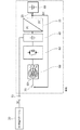
図1は、本発明の一実施形態におけるエネルギー貯蔵器(10)を充電するための充電器(5)の概略ブロック図を示す。直流電源(20)は、DC充電ステーションと同様に、装置(5)の第1の端子(15)に接続される。さらに、装置(5)は、エネルギー貯蔵器(10)が接続される第2の端子(25)を備える。またさらに、充電器(5)は、供給される入力電圧と、出力直流電圧および出力直流電流に供給される入力電流とを変換する2つのトランスデューサ回路(30)(35)と、中間接続回路(40)とを備える。実施形態において、トランスデューサ回路(30)(35)は、直流電圧と回路の入力における直流電流から、回路の出力におけるより低い直流電圧およびより高い直流電流を得るように構成されたDC/DCトランスデューサである。トランスデューサ回路(30)(35)および中間接続回路(40)は、第1の端子(15)および第2の端子(25)との間で互いに並列に接続されている。 FIG. 1 shows a schematic block diagram of a charger (5) for charging an energy storage (10) in one embodiment of the present invention. The DC power supply (20) is connected to the first terminal (15) of the device (5), similar to a DC charging station. Furthermore, the device (5) comprises a second terminal (25) to which the energy storage (10) is connected. Still further, the charger (5) includes two transducer circuits (30) and (35) for converting the supplied input voltage and the input current supplied to the output DC voltage and the output DC current, and the intermediate connection circuit ( 40). In an embodiment, the transducer circuits (30) (35) are DC / DC transducers configured to obtain a lower DC voltage and a higher DC current at the output of the circuit from the DC voltage and the DC current at the input of the circuit. is there. The transducer circuits (30) (35) and the intermediate connection circuit (40) are connected in parallel with each other between the first terminal (15) and the second terminal (25).
並列に接続された2つのトランスデューサ回路(30)(35)を使用することにより、利用可能な入力電力の最適な使用方法は、トランスデューサ回路(30)(35)によってエネルギー貯蔵器(10)の充電電圧に入力電圧を変換し、電圧変換比の逆数による入力電流の強度を変換することである。入力電力は、(要素と線に対応する構成で)制限される必要はない。これは、エネルギー貯蔵器(10)の充電電圧が直流電源(20)の電圧よりも小さく、トランスデューサ回路なしのエネルギー貯蔵器(10)に接続される場合に必要である。この実施形態においては、エネルギー貯蔵器(10)の加速された充電プロセスが有利である。 By using two transducer circuits (30) (35) connected in parallel, the best use of available input power is to charge the energy storage (10) by the transducer circuits (30) (35). Converting the input voltage into a voltage and converting the intensity of the input current by the reciprocal of the voltage conversion ratio. The input power need not be limited (in the configuration corresponding to the elements and lines). This is necessary if the charging voltage of the energy store (10) is smaller than the voltage of the DC power supply (20) and is connected to an energy store (10) without a transducer circuit. In this embodiment, an accelerated charging process of the energy store (10) is advantageous.
充電器(5)は、例えばバッテリまたはコンデンサなどのエネルギー貯蔵器(10)とともに、電気自動車などの車両(42)に設置されてもよく、第1の端子(15)は、直流電源(20)に接続するために車両の外部に取り付けられていてもよい。しかし、充電器(5)は、車両(42)に使用されることに限定されず、むしろあらゆるエネルギー貯蔵器を充電するために使用することができる。特に大きな利点は、大容量のエネルギー貯蔵器における使用であり、その充電プロセスは、DC充電ステーションを使用することによって加速されることである。 The charger (5) may be installed in a vehicle (42) such as an electric vehicle, together with an energy storage (10) such as a battery or a capacitor, and the first terminal (15) may be connected to a DC power supply (20). To be connected to the outside of the vehicle. However, the charger (5) is not limited to being used in the vehicle (42), but rather can be used to charge any energy storage. A particularly great advantage is the use in large energy stores, the charging process of which is accelerated by using a DC charging station.
充電装置が、例えば電気自動車、のようなエネルギー貯蔵器のAC充電およびDC充電の両方に使用され得る、本発明のさらなる実施形態を以下に説明する。 A further embodiment of the invention is described below in which the charging device can be used for both AC and DC charging of an energy storage, such as an electric vehicle, for example.
電気自動車のバッテリの充電は、(単相または三相の)AC充電またはDC充電によってケーブルを使用して行うことができる。ドイツにおける電力インフラ(家庭接続)は、一般に3相(3L+N)のものであり、最大43kW(400V/63A)の電力に達する。DC充電システムは、固定の外部充電システムを必要とし、通常、より高い充電電力において、通電量の面で適切なポイントで使用される。既存の車両用プラグ装置を用いた急速充電ステーションでは、最大107kW(850V/200)の充電電力は理論的には可能である。これにより、充電時間が大幅に短縮される。両方の電荷変動に対応するために、いわゆる「複合AC/DC充電システム」(CCS)が導入されている。これは、充電プラグ、充電ソケット、およびAC接続とDC充電の両方に使用できるケーブル接続を標準化する。 Charging of the battery of an electric vehicle can be performed using a cable by AC charging (single-phase or three-phase) or DC charging. The power infrastructure (home connection) in Germany is generally of three phases (3L + N) and reaches a maximum power of 43 kW (400V / 63A). DC charging systems require a fixed external charging system and are typically used at higher charging powers at the appropriate point in terms of power delivery. In a rapid charging station using an existing vehicle plug device, a maximum charging power of 107 kW (850 V / 200) is theoretically possible. Thereby, the charging time is significantly reduced. To accommodate both charge variations, a so-called "combined AC / DC charging system" (CCS) has been introduced. This standardizes charging plugs, charging sockets and cable connections that can be used for both AC and DC charging.
市場で入手可能な標準化されたDCプラグ接続(IEC レイヤー 62196−3)は、200Aの通電能力に制限されており、これは直接接続の従来の車両バッテリ(200−400V)の電圧では、最大約40〜80kWの電力転送に留まる。対応範囲、ひいては車両バッテリの容量の増加が将来恐らく必要になるため、充電時間を制限範囲内に保つためには充電電力を等しく増加させなければならない。電流が200Aに制限されているため、より高いDC充電電力を転送するためには、充電ケーブルの電圧を増加させる必要が生じる。低バッテリ電圧に適合させるには、車両内に、例えば降圧コンバータのような適合手段(DC/DCトランスデューサ)が必要となる。 The standardized DC plug connection available on the market (IEC layer 62196-3) is limited to a current carrying capacity of 200 A, which is up to about a voltage of a directly connected conventional vehicle battery (200-400 V). Stay at 40-80 kW power transfer. In order to possibly increase the capacity and thus the capacity of the vehicle battery in the future, the charging power must be increased equally to keep the charging time within the limit. Since the current is limited to 200 A, it is necessary to increase the voltage of the charging cable to transfer higher DC charging power. Adaptation to low battery voltages requires adaptation means (DC / DC transducers) in the vehicle, such as, for example, a buck converter.
実施形態において、充電器は電気自動車のAC充電およびDC充電の両方に使用される。図2は、電気自動車用の公知のAC充電器、例えば三相交流充電器、を示す。さらに、AC充電器は単相、二相または多相の充電器として実施されてもよい。 In embodiments, the charger is used for both AC and DC charging of electric vehicles. FIG. 2 shows a known AC charger for an electric vehicle, for example, a three-phase AC charger. Further, the AC charger may be implemented as a single-phase, two-phase or multi-phase charger.
図2は、エネルギー貯蔵器(10)を含む車両(42)と、電源網またはグリッド(55)(AC電源)に接続するための第3の端子(50)と、充電器(6)を概略的に示す。充電器(6)は、出力における直接電力への電力変換を行うため、2つのトランスデューサ回路(30)(35)を備える。図示の充電器(6)では、第1のトランスデューサ回路(30)はインバータ/整流器(AC/DCトランスデューサ)を、第2のトランスデューサ回路(35)はDC/DCトランスデューサを備える。さらに、中間接続回路(40)が示されている。第1および第2トランスデューサ回路(30)(35)および中間接続回路(40)は、第2の端子(25)および第3の端子(50)の間に直列に接続されている。実施形態において、既知の充電器ではDC中間回路(40)に接続された直流電圧は降下され、貯蔵ユニット、例えばエネルギー貯蔵器(10)(図1)、のDC充電に使用されるように以下でより詳細に示される方法で修正される。したがって、少なくとも2つの並列のブーストコンバータまたは降圧コンバータが形成されるように、AC/DCトランスデューサおよび第2のDC/DCトランスデューサからなる少なくとも1つのハーフブリッジおよび1つのチョークが並列に接続される。DC充電のための転送可能な電力を最大化するために、全ての電力電子ブリッジおよびこれらに接続されたチョークは、実施形態において使用される。 FIG. 2 schematically shows a vehicle (42) including an energy storage (10), a third terminal (50) for connection to a power grid or grid (55) (AC power supply), and a charger (6). Is shown. The charger (6) comprises two transducer circuits (30) (35) for performing power conversion to direct power at the output. In the illustrated charger (6), the first transducer circuit (30) comprises an inverter / rectifier (AC / DC transducer) and the second transducer circuit (35) comprises a DC / DC transducer. Furthermore, an intermediate connection circuit (40) is shown. The first and second transducer circuits (30) (35) and the intermediate connection circuit (40) are connected in series between the second terminal (25) and the third terminal (50). In an embodiment, in known chargers, the DC voltage connected to the DC intermediate circuit (40) is reduced and used as follows for the DC charging of a storage unit, for example an energy store (10) (FIG. 1). In a more detailed manner. Thus, at least one half-bridge and one choke of an AC / DC transducer and a second DC / DC transducer are connected in parallel so that at least two parallel boost or buck converters are formed. To maximize the transferable power for DC charging, all power electronic bridges and the chokes connected to them are used in embodiments.
実施形態によれば、DC充電では、AC充電器の中間接続回路(40)は外部のDC電圧と、既に存在する第2のDC/DCトランスデューサ(35)と並列に動作する図1のDC/DCトランスデューサ(30)の機能を有するように入力フィルタで切り替えられて貯蔵器(10)に接続されたAC/DCトランスデューサに接続される。したがって、すべてのハーフブリッジおよびチョークを使用することにより、DC充電では、AC充電に比べて少なくとも2倍の電力が転送される。 According to an embodiment, for DC charging, the intermediate connection circuit (40) of the AC charger operates in parallel with the external DC voltage and the already existing second DC / DC transducer (35) of FIG. It is switched by an input filter to have the function of a DC transducer (30) and is connected to an AC / DC transducer connected to the reservoir (10). Thus, by using all half bridges and chokes, DC charging transfers at least twice as much power as AC charging.
このようなDC充電動作では、結果は図1の強調矢印で示されるような電力の流れとなる。或いは、DC充電動作では、例えば、図3において強調矢印で示される電力の流れが、トランスデューサ回路(30)を介してのみ生じるように変換されたAC/DCトランスデューサ(DC/DCトランスデューサとして有効)のみが使用されてもよい。 In such a DC charging operation, the result is a power flow as indicated by the emphasized arrow in FIG. Alternatively, in the DC charging operation, for example, only the AC / DC transducer (effective as a DC / DC transducer) converted so that the power flow indicated by the emphasized arrow in FIG. 3 is generated only through the transducer circuit (30). May be used.
図3はさらに、充電器(5)がAC端子(50)とは別に、中間接続回路(40)にDC電力を印加するためにDC端子(15)をも備えることを示している。第1のトランスデューサ回路(30)は、AC動作においてはAC/DCトランスデューサとして使用され、DC動作においてはDC/DCトランスデューサ(降圧コンバータ)として使用される。 FIG. 3 further shows that the charger (5) also comprises, apart from the AC terminal (50), a DC terminal (15) for applying DC power to the intermediate connection circuit (40). The first transducer circuit (30) is used as an AC / DC transducer in AC operation and as a DC / DC transducer (step-down converter) in DC operation.
実施形態において、車両内に既に存在するAC充電システムの半導体および他の構成要素は、複合充電システムの複雑な要素およびコストが低くなるように特別に使用される。準同程度の複雑さをもつこのシステムは、非常に高い電力および高い非効率性を有するACおよびDC充電の両方に使用される。 In embodiments, the semiconductor and other components of the AC charging system already present in the vehicle are specifically used to reduce the complexity and cost of the combined charging system. This system of similar complexity is used for both AC and DC charging with very high power and high inefficiency.
複合のAC/DC充電システムの実施形態は、図4および図5に示す。 An embodiment of a combined AC / DC charging system is shown in FIGS.
図4は、複合のAC/DC充電器として構成された充電器(5)の概略ブロック回路図を示す。この実施形態では、充電器(5)の電力は、交流電源(55)、例えば電流供給網、または電流供給網によって供給される直流電源(20)によって供給されてもよい。先に示されているように、直流電源(20)は第1の端子(15)に接続されている、或いは、交流電源(55)は第3の端子(50)に接続されている。 FIG. 4 shows a schematic block circuit diagram of the charger (5) configured as a combined AC / DC charger. In this embodiment, the power of the charger (5) may be supplied by an AC power supply (55), for example a current supply network or a DC power supply (20) supplied by the current supply network. As indicated earlier, the DC power supply (20) is connected to the first terminal (15), or the AC power supply (55) is connected to the third terminal (50).
直流充電モード、すなわち直流電源(20)が第1の端子(15)に接続されている場合、第1のトランスデューサ回路(30)(第1のDC/DCトランスデューサ)と、第2のトランスデューサ回路(35)(第2のDC/DCトランスデューサ)と、中間接続回路(40)は、エネルギー貯蔵器(10)が接続される第1の端子(15)と第2の端子(25)との間に並列接続を形成する。第1のトランスデューサ回路(30)は、半導体スイッチ(60)、例えばブリッジ回路、およびそれに接続されたメインチョーク(65)を備える。メインチョーク(65)と第2の端子(25)とを電気的に接続するスイッチ(70)はメインチョーク(65)に接続されている。 In the DC charging mode, that is, when the DC power supply (20) is connected to the first terminal (15), the first transducer circuit (30) (the first DC / DC transducer) and the second transducer circuit ( 35) (second DC / DC transducer) and an intermediate connection circuit (40) between the first terminal (15) and the second terminal (25) to which the energy storage (10) is connected. Form a parallel connection. The first transducer circuit (30) comprises a semiconductor switch (60), for example a bridge circuit, and a main choke (65) connected thereto. A switch (70) for electrically connecting the main choke (65) and the second terminal (25) is connected to the main choke (65).
交流充電モードでは、直流電源(55)は、第3の端子(50)に接続されている。第1のトランスデューサ回路(30)(AC/DCトランスデューサ)と、中間接続回路と、第2のトランスデューサ回路(35)(DC/DCトランスデューサ)は、エネルギー貯蔵器(10)が接続されている第3の端子(50)と第2の端子(25)の間に直列に接続されている。AC/DCトランスデューサは、グリッドチョーク(75)と、スイッチ(70)と、メインチョーク(65)と、半導体スイッチ(60)からなる直列接続を備える。ここに示す交流充電モードでは、先に示されている直流充電モードでメインチョーク(65)を第2の出力(25)に接続したスイッチ(70)は、グリッドチョーク(75)とメインチョーク(65)が互いに接続されるように切り替えらことできる。 In the AC charging mode, the DC power supply (55) is connected to the third terminal (50). The first transducer circuit (30) (AC / DC transducer), the intermediate connection circuit and the second transducer circuit (35) (DC / DC transducer) are connected to the third energy storage (10). Are connected in series between the terminal (50) and the second terminal (25). The AC / DC transducer comprises a series connection consisting of a grid choke (75), a switch (70), a main choke (65) and a semiconductor switch (60). In the AC charging mode shown here, the switch (70) that connects the main choke (65) to the second output (25) in the DC charging mode shown earlier turns the grid choke (75) and the main choke (65). ) Can be switched to be connected to each other.
すなわち、提案された複合充電器は、貯蔵ユニット、例えばエネルギー貯蔵器(10)と、DC/DCトランスデューサ、例えば第2のトランスデューサ回路(35)と、中間回路、例えば中間接続回路(40)と、有効電力電子スイッチ、例えばB6ブリッジ(3レベルトポロジー)のような半導体スイッチ(60)と、メインチョーク(65)およびグリッドチョーク(75)とスイッチ(70)のような1つまたは複数の切換スイッチを含むネットワーク側スイッチとを備える。スイッチ(70)は、フィルタ素子(65)(75)の間に配置される。メインチョーク(65)および/またはグリッドチョーク(75)がない、さらなる実施形態も実現可能である。 That is, the proposed combined charger comprises a storage unit, for example, an energy storage (10), a DC / DC transducer, for example, a second transducer circuit (35), and an intermediate circuit, for example, an intermediate connection circuit (40); An active power electronic switch, for example a semiconductor switch (60) such as a B6 bridge (three-level topology) and one or more changeover switches such as a main choke (65) and a grid choke (75) and a switch (70). And a network-side switch. The switch (70) is arranged between the filter elements (65) and (75). Further embodiments without the main choke (65) and / or the grid choke (75) are also feasible.
フィルタのグリッドチョーク(75)は、チョークと、この実施形態では、コンデンサとを含む。交流充電モードでは、スイッチ(70)は、グリッドチョーク(75)(またはスイッチ(70)の前のフィルタ素子)をメインチョーク(65)(またはスイッチ(70)の背後のフィルタ素子)に接続する。したがって、システム全体は、入力フィルタ(メインチョーク(65)およびグリッドチョーク(75))、インバータ、例えば半導体スイッチ(60)、中間接続回路(40)および第2のトランスデューサ回路(35)(DC/DCトランスデューサ)を含むAC充電システムを含むことができる。DC充電ステーション、例えば直流電源(20)、がエネルギー貯蔵器(10)の電圧より高い電圧を含むDC充電の場合、スイッチ(70)はメインチョーク(65)をエネルギー貯蔵器(10)に接続する。システム全体はここで(直流充電モードで)1つまたは複数の並列降圧コンバータの機能を有する。 The filter grid choke (75) includes a choke and, in this embodiment, a capacitor. In the AC charging mode, the switch (70) connects the grid choke (75) (or the filter element before the switch (70)) to the main choke (65) (or the filter element behind the switch (70)). Thus, the entire system consists of input filters (main choke (65) and grid choke (75)), inverters such as semiconductor switches (60), intermediate connection circuits (40) and second transducer circuits (35) (DC / DC). (Transducer). In the case of a DC charging station, for example a DC power supply (20), for DC charging including a voltage higher than the voltage of the energy store (10), the switch (70) connects the main choke (65) to the energy store (10). . The entire system now has the function of one or more parallel buck converters (in DC charging mode).
図5は、複合のAC/DC充電器として構成された装置(5)の概略回路図を示す。この実施形態では、装置(5)の三相構成を示す。さらなる実施形態は1相、2相、または任意の数の位相の使用を実現可能にする。 FIG. 5 shows a schematic circuit diagram of a device (5) configured as a combined AC / DC charger. In this embodiment, a three-phase configuration of the device (5) is shown. Further embodiments allow for the use of one phase, two phases, or any number of phases.
交流充電モードでは、装置(5)のエネルギー供給は、交流源(55)、この実施形態では第3の端子(50)の極50a、50b、50c、50dに接続された三相交流源、を用いて行われる。また、充電器(5)を直流充電モードで動作させる場合には、直流電源(20)を第1の端子(15)の極15a、15bに接続してもよい。このように、第1の端子(15)と第2の端子(25)との間に並列に接続された第1及び第2のトランスデューサ回路(30)(35)と中間接続回路(40)との並列接続を用いて直流充電モードが実現される。第1のトランスデューサ回路(30)(DC/DCトランスデューサ)は、例えばB6ブリッジのような半導体スイッチS1〜S6のブリッジ、によって構成される半導体スイッチ(60)を備える。半導体スイッチS1〜S6は、例えば、トランジスタ、サイリスタ、絶縁ゲートバイポーラトランジスタ(IGBT)などで構成される。3つのインダクタンス、LB1、LB2、LB3からなるメインチョーク(65)はB6ブリッジの中央接点に接続されている。3つのインダクタンスは、コイルによって導入することができる。また、三相スイッチ(70)は、メインチョーク(65)の出力を装置(5)の第2の端子(25)に接続する。
In the AC charging mode, the energy supply of the device (5) is powered by an AC source (55), in this embodiment a three-phase AC source connected to the
第2のトランスデューサ回路(35)(第2のDC/DCトランスデューサ)は、半導体スイッチS7〜S12を備え、半導体スイッチS7〜S12はさらにB6ブリッジを形成する。第1のトランスデューサ回路に類似して、半導体スイッチはトランジスタ、サイリスタ、またはIGBTとして導入することができる。第2の端子(25)に出力が接続されたインダクタンスLC1、LC2、LC3を有する3つのコイルは、B6ブリッジ回路の中央接点に接続される。さらに、第2の端子(25)のコンデンサC4は、エネルギー貯蔵器(10)に並列に接続されている。コンデンサC4は、第1および第2のトランスデューサ回路(30)(35)および中間接続回路(40)の並列接続の信号、または信号の流れを平滑化することができる。中間接続回路(40)は、コンデンサC5とコンデンサC6によって構成される。さらなる実施形態では、中間接続回路(40)、第1のDC/DCトランスデューサ(30)および第2のDC/DCトランスデューサ(35)の他の実現化も可能である。 The second transducer circuit (35) (second DC / DC transducer) comprises semiconductor switches S7 to S12, which also form a B6 bridge. Similar to the first transducer circuit, the semiconductor switch can be implemented as a transistor, thyristor, or IGBT. Three coils with inductances LC1, LC2, LC3 whose outputs are connected to the second terminal (25) are connected to the center contact of the B6 bridge circuit. Furthermore, the capacitor C4 of the second terminal (25) is connected in parallel to the energy storage (10). The capacitor C4 can smooth the signal or the signal flow of the parallel connection of the first and second transducer circuits (30) (35) and the intermediate connection circuit (40). The intermediate connection circuit (40) includes a capacitor C5 and a capacitor C6. In further embodiments, other realizations of the intermediate connection circuit (40), the first DC / DC transducer (30) and the second DC / DC transducer (35) are also possible.
交流充電モードでは、グリッドチョーク(75)、スイッチ(70)、メインチョーク(65)からなる第1のトランスデューサ回路(30)(AC/DCトランスデューサ)は、半導体回路(60)、中間接続回路(40)、第2のDC/DCトランスデューサ(35)に、装置(5)の端子(50)と(25)との間に直列に接続されている。第3の端子(50)の極50a、50b、50cは交流電圧源の位相L1、L2、L3を誘導する。また、第3の端子(50)の極50dは、中性導体(中性線)を誘導する。グリッドチョーク(75)は、3つのラインインダクタ(75a)LA1、LA2、LA3、例えば3つのコイルまたはインダクタンス、および3つのキャパシタンス(75b)C1、C2、C3、例えば3つのコンデンサ、を備える。各コンデンサC1、C2、C3は、三相L1、L2、L3のそれぞれを中性導体(中性線)Nに結合する。三相スイッチ(70)は、コイルとコンデンサとの間のノードをメインチョーク(65)に接続する。メインチョーク(65)、半導体スイッチ(60)、中間接続回路(40)および第2のDC/DCトランスデューサ(35)の設定は、既に直流充電モードにて示し済みである。なお、メインチョーク(65)と半導体スイッチ(60)は、交流充電モードと直流充電モードとでは異なる方向に動作する。さらなる実施形態において、半導体スイッチS1〜S6およびS7〜S12は、別個の制御ユニットまたは共通の制御ユニットによって制御されていてもよい。
In the AC charging mode, the first transducer circuit (30) (AC / DC transducer) including the grid choke (75), the switch (70), and the main choke (65) includes the semiconductor circuit (60) and the intermediate connection circuit (40). ), Connected to the second DC / DC transducer (35) in series between the terminals (50) and (25) of the device (5). The poles 50a, 50b, 50c of the third terminal (50) induce the phases L1, L2, L3 of the AC voltage source. The
すなわち、LCLフィルタは三相スイッチ(70)によって分割されていてもよい。LCLフィルタは、LCLフィルタのグリッドチョーク(75)を構成するグリッドチョーク(75a)LA1、LA2、LA3とコンデンサ(75b)C1、C2、C3、さらにはメインチョーク(65)を構成するメインチョークLB1、LB2、LB3とを備える。スイッチ(70)は、グリッドチョーク(75a)とメインチョーク(65)との間でLCLフィルタを分割してもよい。コンデンサ(75b)は、スイッチ(70)の前後に配置されていてもよい。コンデンサ(75b)がスイッチ(70)の背後に配置される際、直流充電モードでは、エネルギー貯蔵器(10)に並列に印加される。さらに、回路は、半導体スイッチ(60)に形成された3つのハーフブリッジと、中間接続回路(40)と、並列に接続された3つの降圧コンバータ(第2のトランスデューサ回路(35))と、エネルギー貯蔵器(10)を備える。図7に示すように、DC充電のプロセス中、6つの並列降圧コンバータと、AC充電のプロセス中、3つの並列降圧コンバータを備える3相AC充電器が存在する。DCプラスおよびDCマイナスの入力(15a)(15b)は、DC充電のプロセス中に中間回路に直接接続されてもよい。 That is, the LCL filter may be divided by the three-phase switch (70). The LCL filter includes a grid choke (75a) LA1, LA2, LA3 forming a grid choke (75) of the LCL filter and capacitors (75b) C1, C2, C3, and a main choke LB1, forming a main choke (65). LB2 and LB3. The switch (70) may divide the LCL filter between the grid choke (75a) and the main choke (65). The capacitor (75b) may be arranged before and after the switch (70). When the capacitor (75b) is placed behind the switch (70), it is applied in parallel to the energy store (10) in DC charging mode. Further, the circuit includes three half bridges formed in the semiconductor switch (60), an intermediate connection circuit (40), three buck converters (second transducer circuit (35)) connected in parallel, and energy A reservoir (10) is provided. As shown in FIG. 7, during the process of DC charging, there are six parallel buck converters, and during the process of AC charging, there is a three-phase AC charger with three parallel buck converters. The DC plus and DC minus inputs (15a) (15b) may be connected directly to the intermediate circuit during the DC charging process.
寸法 Size
43kWのAC公称電力を備える、変圧器を備えない三相AC充電器が想定される。設定を単純化するためには、同一のB6ブリッジモジュールを2つ、コンバータ(S1〜S6)用に1つと、マルチフェーズDC/DCアダプテーションステージ(S7からS12)用に1つを、使用することが実用的である。 A transformerless three-phase AC charger with 43 kW AC nominal power is envisioned. To simplify the configuration, use two identical B6 bridge modules, one for the converters (S1 to S6) and one for the multiphase DC / DC adaptation stage (S7 to S12). Is practical.
43kWのAC充電では、コンバータの各ブリッジ枝路は63Aの通電能力を要する。実施形態に示されるDC/DCアダプテーションステージ(S7〜S12)の3つのブリッジ枝路を最適に使用するには、230VDCの最小バッテリ電圧(エネルギー貯蔵器(10)の電圧)が考えられる(IDC、max=3x63A=189A)。3つの降圧コンバータは、電流リップルを最小限に抑えるために、位相をずらしてクロックすることができる。 For 43 kW AC charging, each bridge branch of the converter requires a current carrying capacity of 63 A. For optimal use of the three bridge branches of the DC / DC adaptation stages (S7-S12) shown in the embodiment, a minimum battery voltage of 230 VDC (voltage of the energy storage (10)) is conceivable (IDC, max = 3 x 63A = 189A). The three buck converters can be clocked out of phase to minimize current ripple.
DC充電動作に切り替え後は、6つの並列降圧コンバータがある。転送可能なDC充電電力は、86kW(IDC、max=6x63A=378A)より以上になり、バッテリ電圧は、可能なAC充電電力の少なくとも2倍に相当する230Vになる。 After switching to DC charging operation, there are six parallel buck converters. The transferable DC charging power is more than 86 kW (IDC , max = 6 × 63A = 378 A) and the battery voltage is 230 V, which is at least twice as much as possible AC charging power.
DC充電ステーションへの直接的なバッテリ接続と比較すると、図示の実施形態における転送可能な電力は、バッテリ充電電流がもはや充電プラグ装置の電流搬送能力(200A)に直接依存しないため、約378A/200A=1.9倍に増加する。半導体スイッチの全てがアクティブスイッチであるため、回路も双方向である。 Compared to a direct battery connection to a DC charging station, the transferable power in the illustrated embodiment is about 378A / 200A because the battery charging current is no longer directly dependent on the current carrying capacity (200A) of the charging plug device. = 1.9 times increase. Since all of the semiconductor switches are active switches, the circuit is also bidirectional.
[他の実施形態] [Other embodiments]
さらなる実施形態が図5及び図6に示されている。この実施形態における第1のトランスデューサ回路の機能は、モータコンバータが取り付けられた電気モータによって実行される。一実施形態においてば、電気モータは電気自動車の駆動モータである。 Further embodiments are shown in FIGS. The function of the first transducer circuit in this embodiment is performed by an electric motor with a motor converter attached. In one embodiment, the electric motor is a drive motor of an electric vehicle.
図6は、実施形態の概略的なブロック回路図を示し、ここでは、図4および図5のメインチョーク(65)は、電気モータ(80)の巻線/コイルによって実現される。電気モータ(80)は、第1のトランスデューサ回路(30)の分岐部における充電電流の3相処理(変換)を可能にする3つのインダクタンスLB1、LB2、LB3を備える。モータ動作モードにおいて、電気モータ(80)は、エネルギー貯蔵器(10)によって作動させることができるように、スイッチ(70)は開いている。さらに、電気モータ(80)のスターまたは中性点(85)が第2の端子(25)に電気的に接続されるようにスイッチ(70)を閉じることができる。 FIG. 6 shows a schematic block circuit diagram of an embodiment, wherein the main choke (65) of FIGS. 4 and 5 is realized by windings / coils of an electric motor (80). The electric motor (80) comprises three inductances LB1, LB2, LB3 that enable three-phase processing (conversion) of the charging current in the branch of the first transducer circuit (30). In the motor operating mode, the switch (70) is open so that the electric motor (80) can be operated by the energy store (10). Further, the switch (70) can be closed such that the star or neutral point (85) of the electric motor (80) is electrically connected to the second terminal (25).
図7は、図6に示されるブロック回路図の概略回路図を示す。図5に示される回路と比較すると、図7の回路にはグリッドチョーク(75)が存在しない点で異なる。メインチョーク(65)は、電動モータ(80)の巻線に置換されている。さらに、巻線LB1、LB2、LB3の入力を有する電動モータ(80)は、3つのブリッジ枝路(60)のそれぞれの中心接点に接続されている。スイッチ(70)が閉じられた状態で、巻線LB1、LB2、LB3の出力部に形成されたスターポイント(85)は第2の出力部(25)に接続されている。スイッチ(70)が開いていると、スターポイント(85)は第2の出力部(25)から分離されている。 FIG. 7 shows a schematic circuit diagram of the block circuit diagram shown in FIG. Compared to the circuit shown in FIG. 5, the circuit of FIG. 7 is different in that the grid choke (75) does not exist. The main choke (65) is replaced by a winding of the electric motor (80). Furthermore, an electric motor (80) having inputs of the windings LB1, LB2, LB3 is connected to the respective center contacts of the three bridge branches (60). With the switch (70) closed, the star point (85) formed at the output of the windings LB1, LB2, LB3 is connected to the second output (25). When the switch (70) is open, the star point (85) is disconnected from the second output (25).
すなわち、図7の実施形態は、AC充電器の代わりに駆動コンバータ、例えば半導体スイッチ(60)、を使用するという以前の実施形態の変化形を示し、それは、DC充電のために少なくとも1つの三相ブリッジ(B6、3レベルトポロジー)およびDC/DCトランスデューサ、またはエネルギー貯蔵器(10)と中間接続回路(40)との間の複数の並列DC/DCトランスデューサを含む。スイッチ(70)が開いている場合、回路はモータ(80)を駆動するモータコンバータを形成する。スイッチ(70)が閉じられており、直流である中間接続回路(40)が直流電源(20)に接続されている場合、回路はDC充電に使用できるいくつかの並列降圧コンバータを含むことができる。したがって、DC充電で転送可能な電力は、パワーエレクトロニクスの過大な寸法を必要とせずに、電気駆動電力の倍数に達することがあり得る。[3]とは対照的に、中間接続回路とエネルギー貯蔵器(10)との間のブーストコンバータを使用して、エネルギー貯蔵機器(10)を中間接続回路からさらに分離することなく、モータからDC充電動作への切り替えが可能である。 That is, the embodiment of FIG. 7 shows a variation of the previous embodiment that uses a driving converter, for example, a solid state switch (60), instead of an AC charger, which includes at least one triode for DC charging. Includes a phase bridge (B6, three level topology) and a DC / DC transducer, or a plurality of parallel DC / DC transducers between the energy storage (10) and the intermediate connection circuit (40). When the switch (70) is open, the circuit forms a motor converter that drives the motor (80). If the switch (70) is closed and the DC connection (40) is connected to the DC power supply (20), the circuit can include several parallel buck converters that can be used for DC charging. . Thus, the power transferable by DC charging can reach multiples of the electrical drive power without requiring the oversized dimensions of the power electronics. In contrast to [3], the boost converter between the intermediate connection circuit and the energy storage (10) is used to remove the DC from the motor without further separating the energy storage device (10) from the intermediate connection circuit. Switching to the charging operation is possible.
いくつかの態様は装置に関連して説明されているが、これらの態様は対応する方法の説明も表しているので、装置のブロックまたは要素は、対応する方法ステップまたは特徴であると理解されたい。類似して、方法ステップに関連して、または方法ステップとして記載された態様は、対応するブロックまたは対応するデバイスの詳細または特徴の記述も表す。方法ステップの一部または全部は、例えば、マイクロプロセッサ、プログラム可能なコンピュータまたは電子回路のようなハードウェア装置(またはハードウェア装置の使用)によって実行されてもよい。いくつかの実施形態では、最も重要な方法ステップのいくつかはそのような装置によって実行されてもよい。 Although some aspects are described with reference to the apparatus, these aspects also represent the description of the corresponding method, so it is to be understood that the blocks or elements of the apparatus are the corresponding method steps or features. . Similarly, aspects described in connection with or as a method step also represent a description of the details or characteristics of the corresponding block or the corresponding device. Some or all of the method steps may be performed by a hardware device (or use of a hardware device) such as, for example, a microprocessor, a programmable computer or an electronic circuit. In some embodiments, some of the most important method steps may be performed by such a device.
Claims (2)
直流電源(20)に接続するための第1の端子(15)と、
前記エネルギー貯蔵器(10)に接続するための第2の端子(25)と、
前記第2の端子(25)に直列に接続された第1のトランスデューサ回路(30)、中間回路(40)及び第2のトランスデューサ回路(35)と、を備え、
前記第1の端子(15)は前記中間回路(40)に接続されており、
前記第1のトランスデューサ回路は、前記第2の端子(25)に接続された第1の接続及び前記中間回路(40)に接続された第2の接続を備え、前記第1のトランスデューサ回路は、前記第1の接続と前記第2の接続との間で直列に接続されたスイッチ(70)、モータ(80)及びブリッジ回路(60)をさらに備えており、
前記スイッチ(70)は、第1の設定と第2の設定との間で切り替えるように構成されており、
前記直流電源(20)を用いた充電が行われる第1のモードでは、前記スイッチ(70)を、前記モータ(80)の巻線を前記第1の接続に接続するように前記第1の設定に切り替え、それによって前記第1のトランスデューサ回路をDC/DCトランスデューサとして動作させ、DC/DCトランスデューサとして動作する前記第1のトランスデューサ回路とDC/DCトランスデューサとして動作する前記第2のトランスデューサ回路(35)を前記第1の端子(15)と前記第2の端子(25)との間に並列に接続し、
前記モータ(80)の動作が行われる第2のモードでは、前記スイッチ(70)を、前記モータ(80)の巻線を前記第1の接続から分離するように前記第2の設定に切り替え、それによって前記第1のトランスデューサ回路を電気モータとして動作させ、電気モータとして動作する前記第1のトランスデューサ回路とDC/DCトランスデューサとして動作する前記第2のトランスデューサ回路(35)を前記第2の端子(25)に直列に接続するように構成されている装置(5)。 An apparatus (5) for charging an energy storage (10), comprising:
A first terminal (15) for connection to a DC power supply (20);
A second terminal (25) for connecting to the energy storage (10);
A first transducer circuit (30), an intermediate circuit (40) and a second transducer circuit (35) connected in series to the second terminal (25);
The first terminal (15) is connected to the intermediate circuit (40);
The first transducer circuit comprises a first connection connected to the second terminal (25) and a second connection connected to the intermediate circuit (40), wherein the first transducer circuit comprises: A switch (70), a motor (80), and a bridge circuit (60) connected in series between the first connection and the second connection;
The switch (70) is configured to switch between a first setting and a second setting;
In a first mode in which charging using the DC power supply (20) is performed, the first setting is performed such that the switch (70) connects the winding of the motor (80) to the first connection. , Thereby causing the first transducer circuit to operate as a DC / DC transducer, the first transducer circuit operating as a DC / DC transducer and the second transducer circuit operating as a DC / DC transducer (35) Are connected in parallel between the first terminal (15) and the second terminal (25),
In a second mode in which the operation of the motor (80) is performed, the switch (70) is switched to the second setting so as to disconnect the winding of the motor (80) from the first connection; Thereby, the first transducer circuit operates as an electric motor, and the first transducer circuit operating as an electric motor and the second transducer circuit (35) operating as a DC / DC transducer are connected to the second terminal ( An apparatus (5) configured to be connected in series to 25).
Applications Claiming Priority (2)
| Application Number | Priority Date | Filing Date | Title |
|---|---|---|---|
| DE102014217703.0 | 2014-09-04 | ||
| DE102014217703.0A DE102014217703A1 (en) | 2014-09-04 | 2014-09-04 | DEVICE FOR LOADING AN ENERGY STORAGE |
Related Parent Applications (1)
| Application Number | Title | Priority Date | Filing Date |
|---|---|---|---|
| JP2017512766A Division JP6374600B2 (en) | 2014-09-04 | 2015-09-03 | Device for charging energy storage |
Publications (2)
| Publication Number | Publication Date |
|---|---|
| JP2018201328A JP2018201328A (en) | 2018-12-20 |
| JP6637552B2 true JP6637552B2 (en) | 2020-01-29 |
Family
ID=54035255
Family Applications (2)
| Application Number | Title | Priority Date | Filing Date |
|---|---|---|---|
| JP2017512766A Active JP6374600B2 (en) | 2014-09-04 | 2015-09-03 | Device for charging energy storage |
| JP2018135450A Active JP6637552B2 (en) | 2014-09-04 | 2018-07-19 | Device for charging energy storage |
Family Applications Before (1)
| Application Number | Title | Priority Date | Filing Date |
|---|---|---|---|
| JP2017512766A Active JP6374600B2 (en) | 2014-09-04 | 2015-09-03 | Device for charging energy storage |
Country Status (6)
| Country | Link |
|---|---|
| US (1) | US10367363B2 (en) |
| EP (1) | EP3189575B1 (en) |
| JP (2) | JP6374600B2 (en) |
| CN (1) | CN106716765B (en) |
| DE (1) | DE102014217703A1 (en) |
| WO (1) | WO2016034669A1 (en) |
Cited By (1)
| Publication number | Priority date | Publication date | Assignee | Title |
|---|---|---|---|---|
| US11502596B2 (en) | 2020-01-30 | 2022-11-15 | The Board Of Trustees Of The University Of Illinois | Three-phase differential mode converter |
Families Citing this family (33)
| Publication number | Priority date | Publication date | Assignee | Title |
|---|---|---|---|---|
| DE102015004119A1 (en) * | 2015-03-31 | 2016-10-06 | Audi Ag | Motor vehicle with an electrical energy storage and two charging interfaces, charging system and method |
| DE102016203150A1 (en) * | 2016-02-29 | 2017-08-31 | Robert Bosch Gmbh | Voltage transformer and electric drive system with a voltage converter |
| DE102016122008A1 (en) * | 2016-11-16 | 2018-05-17 | Dr. Ing. H.C. F. Porsche Aktiengesellschaft | All-mains charger |
| CN116788073A (en) * | 2017-01-05 | 2023-09-22 | 通用电气公司 | DC charging circuit and DC charging station for electric vehicle |
| KR20200014830A (en) | 2017-06-12 | 2020-02-11 | 티에이이 테크놀로지스, 인크. | Multilevel Multiquadrant Hysteresis Current Controller and Its Control Method |
| WO2018232403A1 (en) | 2017-06-16 | 2018-12-20 | Tae Technologies, Inc. | Multi-level hysteresis voltage controllers for voltage modulators and methods for control thereof |
| DE102017006199A1 (en) * | 2017-06-30 | 2019-01-03 | Daimler Ag | Charging device for charging an energy storage device of a vehicle, and vehicle with such a charging device |
| DE102017213682A1 (en) | 2017-08-07 | 2019-02-07 | Continental Automotive Gmbh | A battery charging device for a motor vehicle, a method for operating a motor vehicle-side battery charging device, high-voltage vehicle electrical system and use of a battery charging device |
| FR3070910B1 (en) * | 2017-09-12 | 2021-05-07 | Valeo Systemes De Controle Moteur | VEHICLE CHARGER INCLUDING A DC / DC CONVERTER |
| MA50769A (en) * | 2017-10-13 | 2020-08-19 | Ossiaco Inc | ELECTRIC VEHICLE BATTERY CHARGER |
| DE102017221184A1 (en) | 2017-11-27 | 2019-05-29 | Volkswagen Aktiengesellschaft | Power converter component and semiconductor module of such a power converter component |
| DE102018104914A1 (en) * | 2018-03-05 | 2019-09-05 | Dr. Ing. H.C. F. Porsche Aktiengesellschaft | Integrated power box |
| JP2021518733A (en) | 2018-03-22 | 2021-08-02 | ティーエーイー テクノロジーズ, インコーポレイテッド | Systems and methods for power management and control |
| US11511638B2 (en) * | 2018-07-25 | 2022-11-29 | Volvo Truck Corporation | Electrical power converter unit, an electrical power conversion device and an industrial vehicle including this electrical power converter unit |
| DE102018212523B4 (en) * | 2018-07-26 | 2021-07-08 | Vitesco Technologies GmbH | Vehicle-side charging circuit |
| CN109861357A (en) * | 2018-09-07 | 2019-06-07 | 台达电子工业股份有限公司 | Charging/discharging thereof and device |
| DE102018215769A1 (en) * | 2018-09-17 | 2020-03-19 | Continental Automotive Gmbh | Vehicle electrical system with an energy storage and charging connections |
| DE102018124789A1 (en) * | 2018-10-08 | 2020-04-09 | Thyssenkrupp Ag | Fast charging device and electric drive system with such a quick charging device |
| WO2020205574A1 (en) | 2019-03-29 | 2020-10-08 | Tae Technologies, Inc. | Module-based energy systems capable of cascaded and interconnected configurations, and methods related thereto |
| CN112186820A (en) * | 2019-07-02 | 2021-01-05 | 台达电子工业股份有限公司 | Charger and charging method |
| US11458802B2 (en) * | 2019-09-09 | 2022-10-04 | Thermo King Corporation | Optimized power management for a transport climate control energy source |
| DE102020104736A1 (en) | 2020-02-24 | 2021-08-26 | Audi Aktiengesellschaft | Motor vehicle comprising a charging device |
| AU2021256967A1 (en) | 2020-04-14 | 2023-07-20 | Tae Technologies, Inc. | Systems, devices, and methods for charging and discharging module-based cascaded energy systems |
| IL298081A (en) | 2020-05-14 | 2023-01-01 | Tae Tech Inc | Systems, devices, and methods for rail-based and other electric vehicles with modular cascaded energy systems |
| JP7302558B2 (en) * | 2020-09-07 | 2023-07-04 | トヨタ自動車株式会社 | Charging device and method for controlling charging device |
| MX2023003586A (en) | 2020-09-28 | 2023-06-20 | Tae Tech Inc | Multi-phase module-based energy system frameworks and methods related thereto. |
| WO2022072330A1 (en) | 2020-09-30 | 2022-04-07 | Tae Technologies, Inc. | Systems, devices, and methods for intraphase and interphase balancing in module-based cascaded energy systems |
| DE102020213227B3 (en) * | 2020-10-20 | 2021-12-30 | Vitesco Technologies GmbH | Charging circuit with a direct current connection and an alternating current connection as well as an on-board network with a charging circuit |
| DE102021201400A1 (en) | 2021-02-15 | 2022-08-18 | Mahle International Gmbh | Electronic circuit arrangement for a fuel cell arrangement and fuel cell arrangement |
| EP4367770A1 (en) | 2021-07-07 | 2024-05-15 | TAE Technologies, Inc. | Systems, devices, and methods for module-based cascaded energy systems configured to interface with renewable energy sources |
| US11955908B2 (en) * | 2021-07-28 | 2024-04-09 | Apple Inc. | Auto-configurable energy storage system |
| DE102021213518A1 (en) | 2021-11-30 | 2023-06-01 | Lenze Se | frequency converter |
| FR3137620A1 (en) * | 2022-07-08 | 2024-01-12 | Psa Automobiles Sa | ON-BOARD CHARGER SYSTEM FOR CHARGING AT DIFFERENT TERMINAL VOLTAGES, VEHICLE AND METHOD BASED ON SUCH A SYSTEM |
Family Cites Families (19)
| Publication number | Priority date | Publication date | Assignee | Title |
|---|---|---|---|---|
| JPH08256405A (en) | 1995-03-17 | 1996-10-01 | Nippondenso Co Ltd | Battery charger |
| JP3444316B2 (en) | 1995-03-31 | 2003-09-08 | 株式会社デンソー | Charging device |
| JP2000324857A (en) | 1999-03-11 | 2000-11-24 | Toyota Motor Corp | Variety of power units, and equipment, motor driver, and hybrid vehicle provided with the same |
| DE10119985A1 (en) * | 2001-04-24 | 2002-10-31 | Bosch Gmbh Robert | Device for feeding energy into a multi-voltage electrical system of a motor vehicle |
| CN101674948B (en) * | 2007-02-09 | 2013-09-04 | A123系统公司 | Control system of hybrid vehicles with reconfigurable multi-function power converter |
| JP2010051092A (en) | 2008-08-21 | 2010-03-04 | Toyota Motor Corp | Charge system and vehicle including the same |
| FR2943188B1 (en) | 2009-03-11 | 2013-04-12 | Renault Sas | FAST CHARGING DEVICE FOR AN ELECTRIC VEHICLE. |
| DK2363947T3 (en) * | 2010-03-03 | 2012-08-06 | Sma Solar Technology Ag | Inverters with multi-power electrical system |
| WO2012014324A1 (en) * | 2010-07-30 | 2012-02-02 | 三菱電機株式会社 | Electric vehicle propulsion control device, and railway vehicle system |
| JP5383614B2 (en) * | 2010-09-15 | 2014-01-08 | 株式会社東芝 | Vehicle drive system |
| JP2012135141A (en) | 2010-12-22 | 2012-07-12 | Toyota Central R&D Labs Inc | Motor drive system |
| JP5660317B2 (en) | 2011-03-18 | 2015-01-28 | 富士電機株式会社 | Inter-vehicle charger |
| DE102011075927A1 (en) | 2011-05-16 | 2012-11-22 | Fraunhofer-Gesellschaft zur Förderung der angewandten Forschung e.V. | Multifunctional power converter circuit for switching switching-network into different switching states during e.g. charging high-volt battery in electric car, has inductor connected to terminal for providing voltage to another terminal |
| DE102011081725A1 (en) | 2011-08-29 | 2013-02-28 | Robert Bosch Gmbh | Method and device for charging a battery of an electric drive using components of the electric drive |
| JP5726046B2 (en) * | 2011-11-08 | 2015-05-27 | 三菱電機株式会社 | Vehicle power supply system |
| KR101629997B1 (en) * | 2012-01-30 | 2016-06-13 | 엘에스산전 주식회사 | An apparatus for discharhing dc-link capacitor for electric vehicle charger |
| TWI463290B (en) | 2012-03-22 | 2014-12-01 | 中原大學 | Photovoltaic system having power-increment-aided incremental-conductance maximum power point tracking controller using variable-frequency constant-duty control and method thereof |
| DE102012206801A1 (en) | 2012-04-25 | 2013-10-31 | Fraunhofer-Gesellschaft zur Förderung der angewandten Forschung e.V. | Circuit for direct current charging station for charging battery of e.g. electric car, has power converter circuitry that performs voltage switching between direct voltages that rest against respective voltage terminals |
| DE102014101610A1 (en) * | 2013-02-21 | 2014-08-21 | Sma Solar Technology Ag | Inverter e.g. photovoltaic inverter for supplying electrical energy in alternating current power device, has charging circuit to charge capacitive energy storage device to voltage which is specific peak voltage of alternating voltage |
-
2014
- 2014-09-04 DE DE102014217703.0A patent/DE102014217703A1/en not_active Ceased
-
2015
- 2015-09-03 JP JP2017512766A patent/JP6374600B2/en active Active
- 2015-09-03 CN CN201580047848.2A patent/CN106716765B/en active Active
- 2015-09-03 WO PCT/EP2015/070139 patent/WO2016034669A1/en active Application Filing
- 2015-09-03 EP EP15757291.8A patent/EP3189575B1/en active Active
-
2017
- 2017-03-03 US US15/448,820 patent/US10367363B2/en active Active
-
2018
- 2018-07-19 JP JP2018135450A patent/JP6637552B2/en active Active
Cited By (1)
| Publication number | Priority date | Publication date | Assignee | Title |
|---|---|---|---|---|
| US11502596B2 (en) | 2020-01-30 | 2022-11-15 | The Board Of Trustees Of The University Of Illinois | Three-phase differential mode converter |
Also Published As
| Publication number | Publication date |
|---|---|
| US10367363B2 (en) | 2019-07-30 |
| DE102014217703A1 (en) | 2016-03-10 |
| CN106716765B (en) | 2019-10-01 |
| US20170179745A1 (en) | 2017-06-22 |
| EP3189575A1 (en) | 2017-07-12 |
| WO2016034669A1 (en) | 2016-03-10 |
| JP2017528105A (en) | 2017-09-21 |
| CN106716765A (en) | 2017-05-24 |
| JP2018201328A (en) | 2018-12-20 |
| EP3189575B1 (en) | 2020-01-01 |
| JP6374600B2 (en) | 2018-08-15 |
Similar Documents
| Publication | Publication Date | Title |
|---|---|---|
| JP6637552B2 (en) | Device for charging energy storage | |
| US11970067B2 (en) | Constant current fast charging of electric vehicles via DC grid using dual inverter drive | |
| CA2983328C (en) | Constant current fast charging of electric vehicles via dc grid using dual inverter drive | |
| CN109789805B (en) | Device for voltage conversion, traction network and method for charging a battery | |
| EP3628109B1 (en) | Systems and methods for an on-board fast charger | |
| CN109195831B (en) | Vehicle electrical system having an inverter, an energy store, an electric machine and an ac current transmission terminal | |
| CN109311409B (en) | Vehicle electrical system having an inverter, an energy store, an electric machine and a direct current transmission terminal | |
| EP2605396B1 (en) | A track-bound vehicle inverter | |
| JP2020529823A (en) | Battery charging device for automobiles, method for operating storage battery charging device on the automobile side, use of high voltage power supply network and storage battery charging device | |
| EP3928411B1 (en) | Integrated charger and motor control system isolated by motor | |
| CN107921880B (en) | Vehicle-side power circuit for supplying power in an electric vehicle | |
| US11332028B2 (en) | Alternating voltage charging device and method for the single- or multi-phase alternating current charging of a vehicle | |
| JP2020005389A (en) | Power supply system | |
| JP5358309B2 (en) | Multifunctional converter for vehicles | |
| KR20210062670A (en) | Charging circuit for vehicle-side stored electric energy source | |
| KR20210062671A (en) | Charging circuit for vehicle-side electrical energy storage | |
| US20140265971A1 (en) | Battery Charger/Export Power | |
| KR102601772B1 (en) | Vehicle-side charging device | |
| JP2008312283A (en) | Control system for vehicle, and terminal block for dynamo-electric machine |
Legal Events
| Date | Code | Title | Description |
|---|---|---|---|
| A621 | Written request for application examination |
Free format text: JAPANESE INTERMEDIATE CODE: A621 Effective date: 20180719 |
|
| A977 | Report on retrieval |
Free format text: JAPANESE INTERMEDIATE CODE: A971007 Effective date: 20190411 |
|
| A131 | Notification of reasons for refusal |
Free format text: JAPANESE INTERMEDIATE CODE: A131 Effective date: 20190423 |
|
| TRDD | Decision of grant or rejection written | ||
| A01 | Written decision to grant a patent or to grant a registration (utility model) |
Free format text: JAPANESE INTERMEDIATE CODE: A01 Effective date: 20191126 |
|
| A61 | First payment of annual fees (during grant procedure) |
Free format text: JAPANESE INTERMEDIATE CODE: A61 Effective date: 20191220 |
|
| R150 | Certificate of patent or registration of utility model |
Ref document number: 6637552 Country of ref document: JP Free format text: JAPANESE INTERMEDIATE CODE: R150 |
|
| R250 | Receipt of annual fees |
Free format text: JAPANESE INTERMEDIATE CODE: R250 |
|
| R250 | Receipt of annual fees |
Free format text: JAPANESE INTERMEDIATE CODE: R250 |