JP6479810B2 - Carbon conductive substrates for electronic smoking articles - Google Patents
Carbon conductive substrates for electronic smoking articles Download PDFInfo
- Publication number
- JP6479810B2 JP6479810B2 JP2016537761A JP2016537761A JP6479810B2 JP 6479810 B2 JP6479810 B2 JP 6479810B2 JP 2016537761 A JP2016537761 A JP 2016537761A JP 2016537761 A JP2016537761 A JP 2016537761A JP 6479810 B2 JP6479810 B2 JP 6479810B2
- Authority
- JP
- Japan
- Prior art keywords
- smoking article
- heating element
- electronic smoking
- porous carbon
- aerosol precursor
- Prior art date
- Legal status (The legal status is an assumption and is not a legal conclusion. Google has not performed a legal analysis and makes no representation as to the accuracy of the status listed.)
- Active
Links
- OKTJSMMVPCPJKN-UHFFFAOYSA-N Carbon Chemical compound [C] OKTJSMMVPCPJKN-UHFFFAOYSA-N 0.000 title claims description 327
- 229910052799 carbon Inorganic materials 0.000 title claims description 311
- 230000000391 smoking effect Effects 0.000 title claims description 156
- 239000000758 substrate Substances 0.000 title description 9
- 238000010438 heat treatment Methods 0.000 claims description 269
- 239000000443 aerosol Substances 0.000 claims description 246
- 239000002243 precursor Substances 0.000 claims description 206
- 239000000463 material Substances 0.000 claims description 84
- 239000004744 fabric Substances 0.000 claims description 58
- 239000006199 nebulizer Substances 0.000 claims description 38
- 229920000049 Carbon (fiber) Polymers 0.000 claims description 36
- 239000011148 porous material Substances 0.000 claims description 29
- 239000007788 liquid Substances 0.000 claims description 27
- 239000004917 carbon fiber Substances 0.000 claims description 24
- 239000000796 flavoring agent Substances 0.000 claims description 18
- 235000019634 flavors Nutrition 0.000 claims description 18
- 239000003575 carbonaceous material Substances 0.000 claims description 17
- 229910002804 graphite Inorganic materials 0.000 claims description 16
- 239000010439 graphite Substances 0.000 claims description 16
- 239000002657 fibrous material Substances 0.000 claims description 14
- 239000002775 capsule Substances 0.000 claims description 13
- 239000012530 fluid Substances 0.000 claims description 10
- 238000004891 communication Methods 0.000 claims description 6
- 125000004432 carbon atom Chemical group C* 0.000 claims 1
- VNWKTOKETHGBQD-UHFFFAOYSA-N methane Chemical compound C VNWKTOKETHGBQD-UHFFFAOYSA-N 0.000 description 26
- 239000000203 mixture Substances 0.000 description 17
- 210000004027 cell Anatomy 0.000 description 16
- 239000006260 foam Substances 0.000 description 15
- 235000019504 cigarettes Nutrition 0.000 description 13
- 241000208125 Nicotiana Species 0.000 description 10
- 235000002637 Nicotiana tabacum Nutrition 0.000 description 10
- 238000010586 diagram Methods 0.000 description 9
- 230000006870 function Effects 0.000 description 9
- 238000000034 method Methods 0.000 description 9
- 239000000047 product Substances 0.000 description 9
- 239000003570 air Substances 0.000 description 8
- 235000019506 cigar Nutrition 0.000 description 8
- 239000000126 substance Substances 0.000 description 7
- 230000008016 vaporization Effects 0.000 description 7
- DNIAPMSPPWPWGF-UHFFFAOYSA-N Propylene glycol Chemical compound CC(O)CO DNIAPMSPPWPWGF-UHFFFAOYSA-N 0.000 description 6
- 239000000835 fiber Substances 0.000 description 6
- -1 foam carbon Chemical compound 0.000 description 6
- 239000011521 glass Substances 0.000 description 6
- 229910052751 metal Inorganic materials 0.000 description 6
- 239000002184 metal Substances 0.000 description 6
- 238000004806 packaging method and process Methods 0.000 description 6
- 238000001878 scanning electron micrograph Methods 0.000 description 6
- PEDCQBHIVMGVHV-UHFFFAOYSA-N Glycerine Chemical compound OCC(O)CO PEDCQBHIVMGVHV-UHFFFAOYSA-N 0.000 description 5
- YXTPWUNVHCYOSP-UHFFFAOYSA-N bis($l^{2}-silanylidene)molybdenum Chemical compound [Si]=[Mo]=[Si] YXTPWUNVHCYOSP-UHFFFAOYSA-N 0.000 description 5
- 239000004020 conductor Substances 0.000 description 5
- 239000000779 smoke Substances 0.000 description 5
- 238000009834 vaporization Methods 0.000 description 5
- 230000015572 biosynthetic process Effects 0.000 description 4
- 230000001276 controlling effect Effects 0.000 description 4
- 239000003571 electronic cigarette Substances 0.000 description 4
- 230000014759 maintenance of location Effects 0.000 description 4
- 229920000742 Cotton Polymers 0.000 description 3
- 229920002301 cellulose acetate Polymers 0.000 description 3
- 239000000919 ceramic Substances 0.000 description 3
- 238000002485 combustion reaction Methods 0.000 description 3
- 239000007789 gas Substances 0.000 description 3
- 230000020169 heat generation Effects 0.000 description 3
- 239000008263 liquid aerosol Substances 0.000 description 3
- 229910021344 molybdenum silicide Inorganic materials 0.000 description 3
- 230000008447 perception Effects 0.000 description 3
- 238000003860 storage Methods 0.000 description 3
- 244000025254 Cannabis sativa Species 0.000 description 2
- 235000012766 Cannabis sativa ssp. sativa var. sativa Nutrition 0.000 description 2
- 235000012765 Cannabis sativa ssp. sativa var. spontanea Nutrition 0.000 description 2
- 239000004696 Poly ether ether ketone Substances 0.000 description 2
- 229910052782 aluminium Inorganic materials 0.000 description 2
- 235000009120 camo Nutrition 0.000 description 2
- OKTJSMMVPCPJKN-YPZZEJLDSA-N carbon-10 atom Chemical compound [10C] OKTJSMMVPCPJKN-YPZZEJLDSA-N 0.000 description 2
- 230000008859 change Effects 0.000 description 2
- 235000005607 chanvre indien Nutrition 0.000 description 2
- 238000005516 engineering process Methods 0.000 description 2
- 239000011152 fibreglass Substances 0.000 description 2
- 235000011187 glycerol Nutrition 0.000 description 2
- 239000011487 hemp Substances 0.000 description 2
- 238000012986 modification Methods 0.000 description 2
- 230000004048 modification Effects 0.000 description 2
- 229910021343 molybdenum disilicide Inorganic materials 0.000 description 2
- 239000004745 nonwoven fabric Substances 0.000 description 2
- 229920002530 polyetherether ketone Polymers 0.000 description 2
- 238000000197 pyrolysis Methods 0.000 description 2
- 230000004044 response Effects 0.000 description 2
- 229910052710 silicon Inorganic materials 0.000 description 2
- 239000007787 solid Substances 0.000 description 2
- 235000019505 tobacco product Nutrition 0.000 description 2
- 238000012546 transfer Methods 0.000 description 2
- 239000002759 woven fabric Substances 0.000 description 2
- XQMVBICWFFHDNN-UHFFFAOYSA-N 5-amino-4-chloro-2-phenylpyridazin-3-one;(2-ethoxy-3,3-dimethyl-2h-1-benzofuran-5-yl) methanesulfonate Chemical compound O=C1C(Cl)=C(N)C=NN1C1=CC=CC=C1.C1=C(OS(C)(=O)=O)C=C2C(C)(C)C(OCC)OC2=C1 XQMVBICWFFHDNN-UHFFFAOYSA-N 0.000 description 1
- 229920003043 Cellulose fiber Polymers 0.000 description 1
- 241001583810 Colibri Species 0.000 description 1
- 240000001624 Espostoa lanata Species 0.000 description 1
- 235000009161 Espostoa lanata Nutrition 0.000 description 1
- 101100042848 Rattus norvegicus Smok gene Proteins 0.000 description 1
- 101100425901 Rattus norvegicus Tpm1 gene Proteins 0.000 description 1
- XUIMIQQOPSSXEZ-UHFFFAOYSA-N Silicon Chemical compound [Si] XUIMIQQOPSSXEZ-UHFFFAOYSA-N 0.000 description 1
- 238000010521 absorption reaction Methods 0.000 description 1
- 230000009471 action Effects 0.000 description 1
- 239000004480 active ingredient Substances 0.000 description 1
- 238000012387 aerosolization Methods 0.000 description 1
- XAGFODPZIPBFFR-UHFFFAOYSA-N aluminium Chemical compound [Al] XAGFODPZIPBFFR-UHFFFAOYSA-N 0.000 description 1
- 239000012080 ambient air Substances 0.000 description 1
- 230000009286 beneficial effect Effects 0.000 description 1
- 239000011230 binding agent Substances 0.000 description 1
- 230000033228 biological regulation Effects 0.000 description 1
- 230000005540 biological transmission Effects 0.000 description 1
- 239000006227 byproduct Substances 0.000 description 1
- 210000002421 cell wall Anatomy 0.000 description 1
- 239000003795 chemical substances by application Substances 0.000 description 1
- 239000011248 coating agent Substances 0.000 description 1
- 238000000576 coating method Methods 0.000 description 1
- 239000004035 construction material Substances 0.000 description 1
- 239000007799 cork Substances 0.000 description 1
- 230000000593 degrading effect Effects 0.000 description 1
- 238000013461 design Methods 0.000 description 1
- 238000001514 detection method Methods 0.000 description 1
- 238000012377 drug delivery Methods 0.000 description 1
- 238000001035 drying Methods 0.000 description 1
- 238000010828 elution Methods 0.000 description 1
- 238000001704 evaporation Methods 0.000 description 1
- 238000011049 filling Methods 0.000 description 1
- 235000011389 fruit/vegetable juice Nutrition 0.000 description 1
- ZZUFCTLCJUWOSV-UHFFFAOYSA-N furosemide Chemical compound C1=C(Cl)C(S(=O)(=O)N)=CC(C(O)=O)=C1NCC1=CC=CO1 ZZUFCTLCJUWOSV-UHFFFAOYSA-N 0.000 description 1
- 229910021397 glassy carbon Inorganic materials 0.000 description 1
- 239000004615 ingredient Substances 0.000 description 1
- 239000012212 insulator Substances 0.000 description 1
- 229910000953 kanthal Inorganic materials 0.000 description 1
- 239000011344 liquid material Substances 0.000 description 1
- 238000004519 manufacturing process Methods 0.000 description 1
- 230000013011 mating Effects 0.000 description 1
- 230000007246 mechanism Effects 0.000 description 1
- 150000002739 metals Chemical class 0.000 description 1
- 229910001120 nichrome Inorganic materials 0.000 description 1
- 229910052755 nonmetal Inorganic materials 0.000 description 1
- 239000002245 particle Substances 0.000 description 1
- 239000013618 particulate matter Substances 0.000 description 1
- 230000035699 permeability Effects 0.000 description 1
- 230000010363 phase shift Effects 0.000 description 1
- 230000000704 physical effect Effects 0.000 description 1
- 229920000747 poly(lactic acid) Polymers 0.000 description 1
- 239000004626 polylactic acid Substances 0.000 description 1
- 239000011819 refractory material Substances 0.000 description 1
- 239000004627 regenerated cellulose Substances 0.000 description 1
- 230000001105 regulatory effect Effects 0.000 description 1
- 230000000717 retained effect Effects 0.000 description 1
- 230000035807 sensation Effects 0.000 description 1
- 235000019615 sensations Nutrition 0.000 description 1
- 230000001953 sensory effect Effects 0.000 description 1
- 239000010703 silicon Substances 0.000 description 1
- 238000001179 sorption measurement Methods 0.000 description 1
- 150000005846 sugar alcohols Polymers 0.000 description 1
- 229920002994 synthetic fiber Polymers 0.000 description 1
- 239000012209 synthetic fiber Substances 0.000 description 1
- 229920001059 synthetic polymer Polymers 0.000 description 1
- 238000012360 testing method Methods 0.000 description 1
- 230000000007 visual effect Effects 0.000 description 1
- 239000011800 void material Substances 0.000 description 1
- XLYOFNOQVPJJNP-UHFFFAOYSA-N water Substances O XLYOFNOQVPJJNP-UHFFFAOYSA-N 0.000 description 1
- 239000002023 wood Substances 0.000 description 1
Images


Classifications
-
- A—HUMAN NECESSITIES
- A24—TOBACCO; CIGARS; CIGARETTES; SIMULATED SMOKING DEVICES; SMOKERS' REQUISITES
- A24F—SMOKERS' REQUISITES; MATCH BOXES; SIMULATED SMOKING DEVICES
- A24F40/00—Electrically operated smoking devices; Component parts thereof; Manufacture thereof; Maintenance or testing thereof; Charging means specially adapted therefor
- A24F40/40—Constructional details, e.g. connection of cartridges and battery parts
- A24F40/46—Shape or structure of electric heating means
-
- A—HUMAN NECESSITIES
- A24—TOBACCO; CIGARS; CIGARETTES; SIMULATED SMOKING DEVICES; SMOKERS' REQUISITES
- A24F—SMOKERS' REQUISITES; MATCH BOXES; SIMULATED SMOKING DEVICES
- A24F40/00—Electrically operated smoking devices; Component parts thereof; Manufacture thereof; Maintenance or testing thereof; Charging means specially adapted therefor
- A24F40/40—Constructional details, e.g. connection of cartridges and battery parts
- A24F40/42—Cartridges or containers for inhalable precursors
-
- A—HUMAN NECESSITIES
- A24—TOBACCO; CIGARS; CIGARETTES; SIMULATED SMOKING DEVICES; SMOKERS' REQUISITES
- A24F—SMOKERS' REQUISITES; MATCH BOXES; SIMULATED SMOKING DEVICES
- A24F40/00—Electrically operated smoking devices; Component parts thereof; Manufacture thereof; Maintenance or testing thereof; Charging means specially adapted therefor
- A24F40/40—Constructional details, e.g. connection of cartridges and battery parts
- A24F40/44—Wicks
-
- A—HUMAN NECESSITIES
- A24—TOBACCO; CIGARS; CIGARETTES; SIMULATED SMOKING DEVICES; SMOKERS' REQUISITES
- A24F—SMOKERS' REQUISITES; MATCH BOXES; SIMULATED SMOKING DEVICES
- A24F40/00—Electrically operated smoking devices; Component parts thereof; Manufacture thereof; Maintenance or testing thereof; Charging means specially adapted therefor
- A24F40/10—Devices using liquid inhalable precursors
Description
本開示は、喫煙物品などのエアロゾル送達デバイス、より具体的には、かかるデバイスに有用な電気抵抗発熱体に関する。電気抵抗発熱体は、タバコから作製され得るかまたはタバコに由来し得る、あるいはタバコを組み込み得る材料を加熱して、人間が消費するための吸入可能な物質を形成するように構成され得る。 The present disclosure relates to aerosol delivery devices, such as smoking articles, and more specifically to electrical resistance heating elements useful in such devices. The electrical resistance heating element can be made from tobacco or derived from tobacco, or can be configured to heat a material that can incorporate tobacco to form an inhalable substance for human consumption.
多くの喫煙デバイスが、タバコを燃やすことを必要とする喫煙製品の改良または代替として、長年の間提案されてきた。これらのデバイスの多くは、紙巻きタバコ、葉巻、またはパイプ喫煙と関連付けられる知覚を、タバコの燃焼から生じる不完全燃焼及び熱分解による相当量の生成物を送達することなく、提供するように意図的に設計されてきた。そのために、数多くの喫煙製品、風味生成器、及び薬用吸入器の提案がなされているが、これらは、電気エネルギーを利用して揮発性材料を気化または加熱するか、または、紙巻きタバコ、葉巻、またはパイプ喫煙の知覚を、タバコをかなりの程度燃焼させることなく、提供することを試みるものである。例えば、参照により本明細書に組み込まれる、Robinsonらの米国特許第7,726,320号、2012年3月28日出願の米国特許出願第13/432,406号、2012年6月28日出願の米国特許出願第13/536,438号、2012年9月4日出願の米国特許出願第13/602,871号、及び2012年10月8日出願の米国特許出願第13/647,000号に記載されている背景技術に示されている、種々の代替的な喫煙物品、エアロゾル送達デバイス、及び発熱源を参照されたい。 Many smoking devices have been proposed for many years as improvements or alternatives to smoking products that require burning tobacco. Many of these devices are intended to provide the perception associated with cigarettes, cigars, or pipe smoking without delivering significant amounts of products from incomplete combustion and pyrolysis resulting from tobacco combustion. Has been designed. To that end, a number of smoking products, flavor generators, and medicinal inhalers have been proposed that use electrical energy to vaporize or heat volatile materials, or to produce cigarettes, cigars, Or it attempts to provide the perception of pipe smoking without burning tobacco to a significant extent. For example, Robinson et al., US Pat. No. 7,726,320, filed Mar. 28, 2012, US Patent Application No. 13 / 432,406, filed Jun. 28, 2012, which is incorporated herein by reference. US Patent Application No. 13 / 536,438, US Patent Application No. 13 / 602,871 filed on September 4, 2012, and US Patent Application No. 13 / 647,000 filed on October 8, 2012. See the various alternative smoking articles, aerosol delivery devices, and heat sources shown in the background art described in.
電気エネルギーを用いて煙またはエアロゾル形成のための熱を生み出すある特定のタバコ製品、具体的には、電子タバコ製品と称されているある特定の製品は、世界中で市販されている。伝統的な種類の紙巻きタバコ、葉巻、またはパイプの属性の多くと類似している代表的な製品は、Philip Morris Incorporated製のACCORD(登録商標);InnoVapor LLC製のALPHA(商標)、JOYE 510(商標)、及びM4(商標);White Cloud Cigarettes製のCIRRUS(商標)及びFLING(商標);Epuffer(登録商標) International Inc.製のCOHITA(商標)、COLIBRI(商標)、ELITE CLASSIC(商標)、MAGNUM(商標)、PHANTOM(商標)、及びSENSE(商標);Electronic Cigarettes,Inc.製のDUOPRO(商標)、STORM(商標)、及びVAPORKING(登録商標);Egar Australia製のEGAR(商標);Joyetech製のeGo−C(商標)及びeGo−T(商標);Elusion UK Ltd製のELUSION(商標);Eonsmoke LLC製のEONSMOKE(登録商標);Green Smoke Inc.USA製のGREEN SMOKE(登録商標)Greenarette LLC製のGREENARETTE(商標);Smoke Stik(登録商標)製のHALLIGAN(商標)、HENDU(商標)、JET(商標)、MAXXQ(商標)、PINK(商標)、及びPITBULL(商標);Philip Morris International,Inc.製のHEATBAR(商標);Crown7製のHYDRO IMPERIAL(商標)及びLXE(商標);LOGIC Technology製のLOGIC(商標)及びTHE CUBAN(商標);Luciano Smokes Inc.製のLUCI(登録商標);Nicotek,LLC製のMETRO(登録商標);Sottera,Inc.製のNJOY(登録商標)及びONEJOY(商標);SS Choice LLC製のNO.7(商標);PremiumEstore LLC製のPREMIUM ELECTRONIC CIGARETTE(商標);Ruyan America,Inc.製のRAPP E−MYSTICK(商標);Red Dragon Products,LLC製のRED DRAGON(商標);Ruyan Group(Holdings)Ltd.製のRUYAN(登録商標);The Smart Smoking Electronic Cigarette Company Ltd.製のSMART SMOKER(登録商標);Coastline Products LLC製のSMOKE ASSIST(登録商標);Smoking Everywhere,Inc.製のSMOKING EVERYWHERE(登録商標);VMR Products LLC製のV2CIGS(商標);VaporNine LLC製のVAPOR NINE(商標);Vapor 4 Life,Inc.製のVAPOR4LIFE(登録商標);E−CigaretteDirect,LLC製のVEPPO(商標)、ならびにR.J.Reynolds Vapor Company製のVUSE(登録商標)として販売されている。また他の電動のエアロゾル送達デバイス、具体的には、いわゆる電子タバコとして特徴付けられるデバイスは、BLU(商標)、COOLER VISIONS(商標)、DIRECT E−CIG(商標)、DRAGONFLY(商標)、EMIST(商標)、EVERSMOKE(商標)、GAMUCCI(登録商標)、HYBRID FLAME(商標)、KNIGHT STICKS(商標)、ROYAL BLUES(商標)、SMOKETIP(登録商標)、及びSOUTH BEACH SMOKE(商標)という商品名で販売されている。更に、電子喫煙物品の製造に関する進歩も望ましい。 Certain tobacco products that use electrical energy to generate heat for smoke or aerosol formation are commercially available worldwide, specifically referred to as electronic tobacco products. Representative products that are similar to many of the attributes of traditional types of cigarettes, cigars, or pipes are ACCORD® from Philip Morris Incorporated; ALPHA ™, JOYE 510 from InnoVapor LLC. (Trademark), and M4 (trademark); CIRRUS (trademark) and FLING (trademark) made by White Cloud Cigarettes; Epffer (trademark) International Inc. Manufactured by COHITA ™, COLIBRI ™, ELITE CLASSIC ™, MAGNUM ™, PHANTOM ™, and SENSE ™; Electronic Cigarettes, Inc. DUOPRO (TM), STORM (TM), and VAPORKING (R) manufactured by Egar Australia; EGAR (TM) manufactured by Joyetech; eGo-C (TM) and eGo-T (TM) manufactured by Joyetech; manufactured by Elution UK Ltd ELUSION ™; EONSMOKE ™ manufactured by Eonsmoke LLC; Green Smoke Inc. GREEN SMTE (registered trademark) Greenarette manufactured by USA GREENARETE (trademark) manufactured by LLC; HALLIGAN (trademark), HENDU (trademark), JET (trademark), MAXXQ (trademark), PINK (trademark) manufactured by Smoke Stik (registered trademark) , And PITBULL ™; Philip Morris International, Inc. HEATBAR (TM) manufactured by Crown7; HYDRO IMPERIAL (TM) and LXE (TM) manufactured by Crown7; LOGIC (TM) and THE CUBANTM (TM) manufactured by LOGIC Technology; Luciano Smokes Inc. LUCI (registered trademark) manufactured by Nicotek, LLC; METRO (registered trademark) manufactured by Nicotek, LLC; NJOY (registered trademark) and ONEJOY (trademark) manufactured by SS Choice No. manufactured by SS Choice LLC. 7 (TM); PREMIUM ELECTRONIC CIGARTE (TM) manufactured by PremiumEstry LLC; Ruyan America, Inc. RAPP E-MYSTICK ™ manufactured by Red Dragon Products, LLC RED DRAGON ™ manufactured by LLC; Ruyan Group (Holdings) Ltd. RUYAN (registered trademark); The Smart Smoke Electronic Cigarette Company Ltd. SMART SMOKER (registered trademark) manufactured by Coastline Products LLC; SMOK ASSIST (registered trademark) manufactured by Coastline Products LLC; Smoking Everywhere, Inc. SMOKING EVERYWHERE (R) manufactured by VMR Products LLC; VAPOR NINE (TM) manufactured by VaporNine LLC; Vapor 4 Life, Inc. VAPOR4LIFE® from E-CigaretteDirect, LLC, VEPPO ™ from R. J. et al. It is sold as VUSE (registered trademark) manufactured by Reynolds Vapor Company. Still other powered aerosol delivery devices, specifically those characterized as so-called electronic cigarettes, are BLU ™, COOLER VISIONS ™, DIRECT E-CIG ™, DRAGONFLY ™, EMIIST ( Trademark), EVERSMOKE ™, GAMUCCI ™, HYBRID FLAME ™, KIGHT STICKS ™, ROYAL BLUES ™, SMOKETIP ™, and SOUTH BEACH SMOKE ™ Has been. In addition, advances in the manufacture of electronic smoking articles are also desirable.
本開示は、特に電子喫煙物品または同様の蒸気形成デバイスにおけるエアロゾル形成に有用な材料及びその組み合わせに関する。種々の実施形態では、エアロゾル形成に有用な材料は、大部分が炭素材料から構成され得る。特にかかる材料は、電子喫煙物品のカートリッジにおいて使用され得、いくつかの実施形態では、カートリッジの乾燥構成要素は、主にまたは完全に炭素から形成され得る。かかる構造化は、カートリッジの使い捨てという性質を有益に向上させることができる。特に、電子喫煙物品のためのカートリッジ中に典型的に存在する、金属及び合成ポリマー構成要素などの分解の遅い材料を避けることができる。 The present disclosure relates to materials and combinations thereof useful for aerosol formation, particularly in electronic smoking articles or similar vapor forming devices. In various embodiments, materials useful for aerosol formation can be composed largely of carbon materials. In particular, such materials can be used in cartridges for electronic smoking articles, and in some embodiments, the drying component of the cartridge can be formed primarily or entirely from carbon. Such structuring can beneficially improve the disposable nature of the cartridge. In particular, slow degrading materials such as metal and synthetic polymer components that are typically present in cartridges for electronic smoking articles can be avoided.
一態様では、本開示は、泡状炭素などの多孔質炭素材料で形成される電気抵抗発熱体を提供する。多孔質炭素発熱体は、電子喫煙物品またはその構成要素中での使用に適合させることができる。例えば、ある特定の実施形態では、本開示は、電子喫煙物品の噴霧器を提供する。具体的には、この噴霧器は、多孔質炭素で形成される電気抵抗発熱体を備えることができる。好ましくは、多孔質炭素は、電気抵抗発熱体の乾燥質量の約90%以上を構成し得る。いくつかの実施形態では、電気抵抗発熱体は本質的に多孔質炭素からなる。他の実施形態では、電気抵抗発熱体は多孔質炭素からなる。更なる実施形態では、電気抵抗発熱体は、金属及び黒鉛などの多孔質炭素ではない導電性材料を明白に排除し得る。 In one aspect, the present disclosure provides an electrical resistance heating element formed of a porous carbon material such as foam carbon. The porous carbon heating element can be adapted for use in an electronic smoking article or component thereof. For example, in certain embodiments, the present disclosure provides a nebulizer for electronic smoking articles. Specifically, the nebulizer can include an electrical resistance heating element formed of porous carbon. Preferably, the porous carbon may constitute about 90% or more of the dry mass of the electrical resistance heating element. In some embodiments, the electrical resistance heating element consists essentially of porous carbon. In other embodiments, the electrical resistance heating element comprises porous carbon. In further embodiments, the electrical resistance heating element can explicitly exclude metals and conductive materials that are not porous carbon, such as graphite.
電気抵抗発熱要素として使用される多孔質炭素は、特定の特性を特徴とし得る。例えば、多孔質炭素の乾燥質量は、約90%以上炭素であり得る。多孔質炭素は、複数の気孔を備えることを特徴とし得る。好ましくは、気孔の大部分は閉気孔である。より具体的には、気孔の約80容積%以上が閉気孔であり得る。更なる実施形態では、多孔質炭素発熱体は、約0.1g/cm3〜約0.5g/cm3の密度を有することができる。多孔質炭素発熱体は、多孔質炭素発熱体の乾燥質量の約100%以下の水性液体保持容量を有することができる。 Porous carbon used as an electrical resistance heating element can be characterized by specific properties. For example, the dry mass of porous carbon can be about 90% or more carbon. The porous carbon may be characterized by comprising a plurality of pores. Preferably, the majority of the pores are closed pores. More specifically, about 80% by volume or more of the pores may be closed pores. In a further embodiment, the porous carbon heating element can have a density from about 0.1 g / cm 3 to about 0.5 g / cm 3 . The porous carbon heating element can have an aqueous liquid holding capacity of about 100% or less of the dry mass of the porous carbon heating element.
更なる実施形態では、多孔質炭素発熱体は、その抵抗性、及び電流適用時の効果的な発熱を特徴とし得る。例えば、多孔質炭素発熱体は、約1.0×10⁻³Ω・m〜約1.0×10⁻⁴Ω・mの抵抗性を呈し得る。多孔質炭素発熱体は、約1秒〜約3秒の時間、約0.2アンペア〜約12アンペアの電流に供されるときに、約150℃〜約550℃の温度を達成し得る。 In a further embodiment, the porous carbon heating element may be characterized by its resistance and effective heat generation upon application of current. For example, the porous carbon heating element can exhibit a resistance of about 1.0 × 10 −3 Ω · m to about 1.0 × 10 −4 Ω · m. The porous carbon heating element can achieve a temperature of about 150 ° C. to about 550 ° C. when subjected to a current of about 0.2 amperes to about 12 amperes for a time of about 1 second to about 3 seconds.
いくつかの実施形態では、多孔質炭素発熱体はまた、エアロゾル前駆体材料のための貯蔵部として機能してもよい。具体的には、エアロゾル前駆体材料は、泡状炭素発熱体によって含有されるか、その上にコーティングされるか、それによって吸収されるか、またはその上に吸着し得る。 In some embodiments, the porous carbon heating element may also function as a reservoir for the aerosol precursor material. Specifically, the aerosol precursor material may be contained by, coated on, absorbed by, or adsorbed onto the foam carbon heating element.
他の実施形態では、噴霧器は、多孔質炭素発熱体に加えて、エアロゾル前駆体輸送要素を含んでもよい。具体的には、エアロゾル前駆体輸送要素は、多孔質炭素発熱体と直接接触するように配列することができる。いくつかの実施形態では、エアロゾル前駆体輸送要素は、多孔質炭素発熱体を取り囲むことができる。他の実施形態では、エアロゾル前駆体輸送要素は繊維状材料であり得る。更なる実施形態では、エアロゾル前駆体輸送要素は毛細管を備えることができる。更なる実施形態では、エアロゾル前駆体輸送要素は、泡状炭素発熱体の中に少なくとも部分的に埋め込むことができる。 In other embodiments, the nebulizer may include an aerosol precursor transport element in addition to the porous carbon heating element. Specifically, the aerosol precursor transport element can be arranged in direct contact with the porous carbon heating element. In some embodiments, the aerosol precursor transport element can surround the porous carbon heating element. In other embodiments, the aerosol precursor transport element can be a fibrous material. In a further embodiment, the aerosol precursor transport element can comprise a capillary tube. In a further embodiment, the aerosol precursor transport element can be at least partially embedded in the foam carbon heating element.
特定の実施形態では、エアロゾル前駆体輸送要素は炭素繊維で形成することができる。炭素繊維エアロゾル前駆体輸送要素は、約85%以上の炭素の乾燥質量を有し得る。より具体的には、炭素繊維エアロゾル前駆体輸送要素は、炭素化布帛を含むことができる。エアロゾル前駆体輸送要素は更に、エアロゾル前駆体材料を含むことができる。 In certain embodiments, the aerosol precursor transport element can be formed of carbon fibers. The carbon fiber aerosol precursor transport element can have a dry mass of about 85% or more carbon. More specifically, the carbon fiber aerosol precursor transport element can comprise a carbonized fabric. The aerosol precursor transport element can further include an aerosol precursor material.
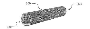
いくつかの実施形態では、多孔質炭素発熱体は、細長く、第1の端部を有し、第2の反対の端部を有し得る。片方の端部または両方の端部は、電力源との電気接続に適合させることができる。 In some embodiments, the porous carbon heating element is elongated, has a first end, and may have a second opposite end. One end or both ends can be adapted for electrical connection with a power source.
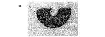
エアロゾル前駆体輸送要素は、多孔質炭素発熱体へのエアロゾル前駆体材料の伝達を促進するのに有用な種々の構造をとることができる。一実施形態では、エアロゾル前駆体輸送要素は、多孔質炭素発熱体を部分的にのみ取り囲むように、実質的に弧状であり得る。例えば、弧状のエアロゾル前駆体輸送要素は、多孔質炭素発熱体と少なくとも部分的に接触している内側弧面、及び内側弧面から離間された外側弧面とを有し得る。このように形作られた構成要素は、部分円板として説明されてもよく、内側弧面から外側弧面までで測定された規定幅、及び第1の面から反対の第2の面までで測定された厚さを有し得る。エアロゾル前駆体輸送要素は、多孔質炭素発熱体の第1の端部に近接して位置付けることができる。上記は、いくつかの実施形態におけるエアロゾル前駆体輸送要素の性質の例にすぎず、構成要素の形状を限定するものとして見るべきではない。 The aerosol precursor transport element can take a variety of structures useful for facilitating the transfer of the aerosol precursor material to the porous carbon heating element. In one embodiment, the aerosol precursor transport element can be substantially arcuate so as to only partially surround the porous carbon heating element. For example, the arcuate aerosol precursor transport element can have an inner arc surface that is at least partially in contact with the porous carbon heating element and an outer arc surface spaced from the inner arc surface. A component shaped in this way may be described as a partial disk, measuring a defined width measured from the inner arc surface to the outer arc surface, and from the first surface to the opposite second surface. May have a reduced thickness. The aerosol precursor transport element can be positioned proximate to the first end of the porous carbon heating element. The above is merely an example of the nature of the aerosol precursor transport element in some embodiments and should not be viewed as limiting the shape of the component.
更なる実施形態では、電気接続器を利用することができ、これは、多孔質炭素発熱体の第2の端部と電気接続している第1の端部を有し得、電力源との電気接続に適合された第2の反対の端部を有し得る。特定の実施形態では、電気接続器は非金属製であり得る。例えば、電気接続器は、黒鉛で形成することができる。しかしながら、他の導電性材料を使用してもよい。本明細書で更に考察されるように、更なる要素を含めることで、電池、電気接続器、及び多孔質炭素発熱体を持つ電気回路を完成させることができる。 In a further embodiment, an electrical connector can be utilized, which can have a first end that is in electrical connection with the second end of the porous carbon heating element and is connected to a power source. It may have a second opposite end adapted to the electrical connection. In certain embodiments, the electrical connector can be non-metallic. For example, the electrical connector can be formed of graphite. However, other conductive materials may be used. As further discussed herein, the inclusion of additional elements can complete an electrical circuit having a battery, an electrical connector, and a porous carbon heating element.
別の態様では、本開示は、電子喫煙物品のカートリッジにも関する。カートリッジは、外側筐体またはシェルを備えることができ、制御体への取り付けに適合され得る。カートリッジは、発熱体、液体貯蔵要素、液体輸送要素、電気接続、絶縁体、及びフィルター材料(別々または種々の組み合わせ)などの種々の構成要素含んでもよい。 In another aspect, the present disclosure also relates to a cartridge for an electronic smoking article. The cartridge can comprise an outer housing or shell and can be adapted for attachment to a control body. The cartridge may include various components such as heating elements, liquid storage elements, liquid transport elements, electrical connections, insulators, and filter materials (separate or various combinations).
ある特定の実施形態では、本開示に従う電子喫煙物品のカートリッジは、泡状炭素などの多孔質炭素で形成される細長い電気抵抗発熱体を備えることができ、この多孔質炭素発熱体は、第1の端部と、電力源との電気接続に適合された第2の反対の端部とを有する。カートリッジはまた、多孔質炭素発熱体と直接接続するように配列されたエアロゾル前駆体輸送要素を含み得る。カートリッジは更に、多孔質炭素発熱体の第2の端部と電気接続している第1の端部を有し、電力源との電気接続に適合された第2の反対の端部を有する、電気接続器を備えることができる。カートリッジはまた、多孔質炭素発熱体の第1の端部に近接する第1の端部と、電気接続器の第2の端部に近接する第2の端部とを有する筐体を備えることができる。カートリッジは更に、カートリッジの少なくとも一部分を取り囲む繊維状材料を含み得る。繊維状材料はフィルターであり得、このフィルターは、筐体の第1の端部を越えて延出するフィルター延出部を含み得る。フィルター及び/またはフィルター延出部は、1つ以上の風味カプセルを含むことができる。カートリッジはまた、エアロゾル前駆体材料を含み得る。 In certain embodiments, a cartridge of an electronic smoking article according to the present disclosure can include an elongated electrical resistance heating element formed of porous carbon, such as foam carbon, wherein the porous carbon heating element includes a first And a second opposite end adapted for electrical connection with the power source. The cartridge may also include an aerosol precursor transport element arranged to connect directly with the porous carbon heating element. The cartridge further has a first end in electrical connection with the second end of the porous carbon heating element and a second opposite end adapted for electrical connection with the power source. An electrical connector can be provided. The cartridge also includes a housing having a first end proximate to the first end of the porous carbon heating element and a second end proximate to the second end of the electrical connector. Can do. The cartridge can further include a fibrous material surrounding at least a portion of the cartridge. The fibrous material can be a filter, and the filter can include a filter extension that extends beyond the first end of the housing. The filter and / or filter extension may include one or more flavor capsules. The cartridge can also include an aerosol precursor material.
更なる実施形態では、本開示に従うカートリッジは、単独でまたはいくつかの組み合わせで具現化され得る種々の特徴によって定義することができる。例えば、カートリッジは、以下のうちの1つ以上によって定義してもよい。
・多孔質炭素は、多孔質炭素発熱体の約90質量%以上を構成し得る。
・多孔質炭素の乾燥質量は、約90%以上炭素であり得る。
・多孔質炭素発熱体は、約0.1g/cm3〜約0.5g/cm3の密度を有し得る。
・エアロゾル前駆体輸送要素は、多孔質炭素発熱体を少なくとも部分的に取り囲み得る。
・エアロゾル前駆体輸送要素は、炭素繊維で形成し得る。
・炭素繊維エアロゾル前駆体輸送要素の乾燥質量は、約85%以上炭素であり得る。
・炭素繊維エアロゾル前駆体輸送要素は、炭素化布帛を含み得る。
・炭素化布帛は織布または不織布であり得る。
・炭素繊維エアロゾル前駆体輸送要素は、炭素化ベール、糸、または粗麻を含み得る。
・エアロゾル前駆体輸送要素は、多孔質炭素発熱体と少なくとも部分的に接触している内側弧面と、内側弧面から離間されている外側弧面とを有して、弧状であり得る。
・エアロゾル前駆体輸送要素は、円形、三角形、四角形、星形などの種々の断面形状を有し得る。
・エアロゾル前駆体輸送要素は、多孔質炭素発熱体の第1の端部に近接して位置付けることができる。
・電気接続器は非金属製であり得る。
・電気接続器は黒鉛で形成し得る。
In further embodiments, a cartridge according to the present disclosure can be defined by various features that can be implemented alone or in several combinations. For example, a cartridge may be defined by one or more of the following.
-The porous carbon may constitute about 90% by mass or more of the porous carbon heating element.
The dry mass of the porous carbon can be about 90% or more carbon.
The porous carbon heating element can have a density of about 0.1 g / cm 3 to about 0.5 g / cm 3 .
The aerosol precursor transport element may at least partially surround the porous carbon heating element;
The aerosol precursor transport element can be formed of carbon fibers.
The dry mass of the carbon fiber aerosol precursor transport element can be about 85% or more carbon.
The carbon fiber aerosol precursor transport element can comprise a carbonized fabric.
The carbonized fabric can be a woven fabric or a non-woven fabric.
The carbon fiber aerosol precursor transport element may comprise a carbonized veil, yarn, or coarse hemp.
The aerosol precursor transport element may be arcuate with an inner arc surface in at least partial contact with the porous carbon heating element and an outer arc surface spaced from the inner arc surface.
The aerosol precursor transport element can have various cross-sectional shapes such as circular, triangular, quadrangular, star-shaped, etc.
The aerosol precursor transport element can be positioned proximate to the first end of the porous carbon heating element;
The electrical connector can be non-metallic.
The electrical connector can be made of graphite.
更なる実施形態では、筐体の第2の端部は、電力源を含む動力装置の第1の端部との構造的接続を形成するように適合させることができる。具体的には、構造的接続は螺合接続であり得る。あるいは、構造的接続は、圧入接続またはスナップ接続であり得る。 In a further embodiment, the second end of the housing can be adapted to form a structural connection with the first end of the power plant that includes the power source. In particular, the structural connection can be a screw connection. Alternatively, the structural connection can be a press-fit connection or a snap connection.
ある特定の実施形態では、筐体の第1の端部は、多孔質炭素発熱体の第1の端部に係合するように適合された位置合わせ凹部を含む壁を備えることができる。係合は、多孔質炭素発熱体と筐体との間の電気接続を形成し得る。第1の端部での筐体壁は、エアロゾルの通過に適合された1つ以上の貫通孔を含むことができる。 In certain embodiments, the first end of the housing can comprise a wall that includes an alignment recess adapted to engage the first end of the porous carbon heating element. The engagement may form an electrical connection between the porous carbon heating element and the housing. The housing wall at the first end can include one or more through holes adapted for passage of the aerosol.
他の実施形態では、筐体の第2の端部はフランジを含み得る。具体的には、フランジは、筐体の残りの部分の直径を上回る直径を有することができる。筐体は炭素材料で形成することができる。例えば、炭素材料は黒鉛であり得る。 In other embodiments, the second end of the housing may include a flange. Specifically, the flange can have a diameter that exceeds the diameter of the remaining portion of the housing. The housing can be formed of a carbon material. For example, the carbon material can be graphite.
いくつかの実施形態では、カートリッジは更に、カートリッジの少なくとも一部分を取り囲む繊維状材料を含み得る。繊維状材料はフィルター材料を含み得る。 In some embodiments, the cartridge can further include a fibrous material surrounding at least a portion of the cartridge. The fibrous material can include a filter material.
ある特定の実施形態では、電気接続器、多孔質炭素発熱体、及び筐体は、電気回路を形成することができ、この電気回路はまた、電源及び1つ以上の制御要素(例えば、マイクロコントローラ)を含んでもよい。 In certain embodiments, the electrical connector, the porous carbon heating element, and the housing can form an electrical circuit that also includes a power source and one or more control elements (eg, a microcontroller). ) May be included.
本開示に従うカートリッジは、また更なる様態で定義することができる。例えば、カートリッジは無金属であってもよい。カートリッジの全構成要素の総乾燥質量の大部分は、炭素であり得る。より具体的には、カートリッジの全構成要素の総乾燥質量は、約75%以上炭素であり得る。例示的な実施形態では、本開示に従う電子喫煙物品のカートリッジは、電気抵抗発熱体、エアロゾル前駆体輸送要素、及び筐体で構成され得、これにおいては、カートリッジの総乾燥質量全構成要素の大部分が炭素である。より具体的には、かかるカートリッジは無金属であってもよい。 A cartridge according to the present disclosure can also be defined in a further manner. For example, the cartridge may be metal free. The majority of the total dry mass of all cartridge components can be carbon. More specifically, the total dry mass of all cartridge components can be about 75% or more carbon. In an exemplary embodiment, a cartridge of an electronic smoking article according to the present disclosure may be comprised of an electrical resistance heating element, an aerosol precursor transport element, and a housing, wherein a large total dry mass total component of the cartridge The part is carbon. More specifically, such a cartridge may be metal free.
別の態様では、本開示は、電子喫煙物品に関係し得る。かかる喫煙物品は、筐体またはシェルを備えることができる。具体的には、喫煙物品は、外側筐体を有するカートリッジと、外側筐体を有する別個の制御体とを備えることができ、カートリッジ及び制御体は取り外し可能に接続される。ある特定の実施形態では、本開示に従う電子喫煙物品は、電力源と、泡状炭素などの多孔質炭素で形成される細長い電子抵抗発熱体とを備え、この多孔質炭素発熱体は、第1の端部と、電力源との電気接続に適合された第2の反対の端部とを有する。喫煙物品は更に、多孔質炭素発熱体と直接接続するように配列されたエアロゾル前駆体輸送要素を備えることができる。更なる実施形態では、喫煙物品は、多孔質炭素発熱体の第2の端部と電気接続している第1の端部を有し、電力源との電気接続に適合された第2の反対の端部を有する、電気接続器を更に備えることができる。多孔質炭素発熱体は特に、カートリッジ筐体中に配され、電力源は特に、別個の制御体の筐体中に配列され得る。カートリッジ筐体は、多孔質炭素発熱体の第1の端部に近接する第1の端部と、電気接続器の第2の端部に近接する第2の端部とを有し得る。更に、筐体の第2の端部は、制御体の筐体の第1の端部と構造的接続を形成するように適合させることができる。いくつかの実施形態では、カートリッジ筐体の第1の端部は、多孔質炭素発熱体の第1の端部に係合するように適合された位置合わせ凹部を含む壁を備え、この係合は、多孔質炭素発熱体と筐体との間の電気接続を形成し得る。具体的には、電気接続器、多孔質炭素発熱体、及び筐体が、電気回路を形成し得る。 In another aspect, the present disclosure may relate to an electronic smoking article. Such smoking articles can comprise a housing or shell. Specifically, the smoking article can comprise a cartridge having an outer housing and a separate control body having an outer housing, the cartridge and the control body being detachably connected. In certain embodiments, an electronic smoking article according to the present disclosure comprises a power source and an elongated electronic resistance heating element formed of porous carbon, such as foam carbon, wherein the porous carbon heating element comprises a first And a second opposite end adapted for electrical connection with the power source. The smoking article can further comprise an aerosol precursor transport element arranged to connect directly with the porous carbon heating element. In a further embodiment, the smoking article has a first end that is in electrical connection with the second end of the porous carbon heating element, and a second counter adapted for electrical connection with the power source. An electrical connector having a plurality of ends can be further provided. The porous carbon heating element is in particular arranged in a cartridge housing and the power source can in particular be arranged in a housing of a separate control body. The cartridge housing may have a first end proximate to the first end of the porous carbon heating element and a second end proximate to the second end of the electrical connector. Further, the second end of the housing can be adapted to form a structural connection with the first end of the housing of the control body. In some embodiments, the first end of the cartridge housing comprises a wall including an alignment recess adapted to engage the first end of the porous carbon heating element, the engagement Can form an electrical connection between the porous carbon heating element and the housing. Specifically, the electrical connector, the porous carbon heating element, and the housing can form an electrical circuit.
更なる実施形態では、本開示に従う電子喫煙物品は、エアロゾル前駆体材料を備えることができる。また、電子喫煙物品は、本明細書で別途提供する電子喫煙物の構成要素の特定の説明に関連して定義することができる。故に、噴霧器及びその構成要素の説明、カートリッジ及びその構成要素の説明、ならびに制御体及びその構成要素の説明は全て、種々の組み合わせでの電子喫煙物品に適用することができる。一実施形態では、電子喫煙物品は、電力源と、泡状炭素などの多孔質炭素で形成される電子抵抗発熱体とを備えることができ、この多孔質炭素発熱体は、電力源と無金属で(例えば、無配線で)電気接続している。 In a further embodiment, an electronic smoking article according to the present disclosure can comprise an aerosol precursor material. Also, an electronic smoking article can be defined in connection with a specific description of components of an electronic smoking article provided separately herein. Thus, the description of the nebulizer and its components, the description of the cartridge and its components, and the description of the controller and its components can all be applied to the electronic smoking article in various combinations. In one embodiment, the electronic smoking article can comprise a power source and an electronic resistance heating element formed of porous carbon, such as foamy carbon, the porous carbon heating element comprising the power source and the metal-free (For example, without wiring).
また別の態様では、本開示は、エアロゾル前駆体材料を加熱し、電子喫煙物品などにおいてエアロゾルを形成する方法にも関し得る。一実施形態では、かかる方法は、電子喫煙物品のカートリッジを電子喫煙物品の制御体に接続するステップを含み得る。特に、制御体は、電力源、圧力センサ、電子制御器、及び制御体の筐体で構成され得る。カートリッジは、泡状炭素などの多孔質炭素で形成される細長い電気抵抗発熱体であって、第1の端部及び第2の反対の端部を有する多孔質炭素発熱体;多孔質炭素発熱体と直接接触するように配列されたエアロゾル前駆体輸送要素;多孔質炭素発熱体の第2の端部と電気接続している第1の端部を有し、電力源との電気接続に適合された第2の反対の端部を有する電気接続器;ならびに、多孔質炭素発熱体の第1の端部に係合するように適合された位置合わせ凹部を持つ端壁を含む第1の端部、及び電気接続器の第2の端部に近接する第2の端部を有し、筐体の第2の端部が、制御体の筐体の第1の端部と構造的接続を形成するように適合され、電気接続器、多孔質炭素発熱体、及びカートリッジ筐体が、電気回路を形成する、カートリッジ筐体、を備えることができる。本方法は更に、電子喫煙物品中で圧力変化を引き起こすことによって、圧力センサが電子制御器に信号を送り、電力源からカートリッジへの電流の流れを引き起こすステップと、多孔質炭素発熱体の発熱を引き起こすように、電流を、カートリッジの電気回路を通して流すステップと、エアロゾル前駆体輸送要素中のエアロゾル前駆体材料が、蒸発し、空気と混合され、エアロゾルを形成するようにするステップと、を含み得る。 In yet another aspect, the present disclosure may also relate to a method of heating an aerosol precursor material to form an aerosol in an electronic smoking article or the like. In one embodiment, such a method may include connecting a cartridge of electronic smoking article to a control body of the electronic smoking article. In particular, the control body may be composed of a power source, a pressure sensor, an electronic controller, and a housing of the control body. The cartridge is an elongated electrical resistance heating element formed of porous carbon, such as foam carbon, having a first end and a second opposite end; a porous carbon heating element; An aerosol precursor transport element arranged to be in direct contact with the first end; having a first end in electrical connection with the second end of the porous carbon heating element and adapted for electrical connection with a power source An electrical connector having a second opposite end; and a first end including an end wall having an alignment recess adapted to engage the first end of the porous carbon heating element , And a second end proximate to the second end of the electrical connector, the second end of the housing forming a structural connection with the first end of the housing of the control body The cartridge, the electrical connector, the porous carbon heating element, and the cartridge housing form an electrical circuit. Housing may comprise. The method further includes causing a pressure change in the electronic smoking article to cause the pressure sensor to send a signal to the electronic controller to cause a current flow from the power source to the cartridge, and to generate heat from the porous carbon heating element. Causing current to flow through the electrical circuitry of the cartridge and causing the aerosol precursor material in the aerosol precursor transport element to evaporate and mix with air to form an aerosol. .
種々の実施形態では、本開示に従う電子喫煙物品は、いずれの組み合わせでも、以下のうちの1つ以上によって定義することができる。 In various embodiments, an electronic smoking article according to the present disclosure can be defined in any combination by one or more of the following.
本電子喫煙物品は、多孔質炭素で形成される電気抵抗発熱体を含む噴霧器を備えることができ、この多孔質炭素発熱体は、第1の端部と、電力源との電気接続に適合された第2の反対の端部とを有する。 The electronic smoking article can include a nebulizer including an electrical resistance heating element formed of porous carbon, the porous carbon heating element being adapted for electrical connection between a first end and a power source. And a second opposite end.
多孔質炭素は、電気抵抗発熱体の乾燥質量の約90%以上を構成し得る。 Porous carbon can constitute about 90% or more of the dry mass of the electrical resistance heating element.
多孔質炭素の乾燥質量は、約90%以上炭素であり得る。 The dry mass of the porous carbon can be about 90% or more carbon.
多孔質炭素中の気孔の大部分が閉気孔であり得る。 Most of the pores in the porous carbon can be closed pores.
気孔の約80容積%以上が閉気孔であり得る。 About 80% by volume or more of the pores can be closed pores.
多孔質炭素発熱体は、約1秒〜約3秒の時間、約0.2アンペア〜約12アンペアの電流に供されるときに、約150℃〜約550℃の温度に発熱するように適合させることができる。 The porous carbon heating element is adapted to generate heat to a temperature of about 150 ° C. to about 550 ° C. when subjected to a current of about 0.2 amperes to about 12 amperes for a time of about 1 second to about 3 seconds. Can be made.
多孔質炭素発熱体は、約0.1g/cm3〜約0.75g/cm3の密度を有し得る。 The porous carbon heating element can have a density of about 0.1 g / cm 3 to about 0.75 g / cm 3 .
多孔質炭素発熱体は、泡状炭素発熱体の乾燥質量の約100%以下の水性液体保持容量を有することができる。 The porous carbon heating element can have an aqueous liquid holding capacity of about 100% or less of the dry mass of the foam carbon heating element.
電子喫煙物品は、多孔質炭素発熱体の上にコーティングされた、それによって吸収された、またはその上に吸着した、エアロゾル前駆体材料を更に含み得る。 The electronic smoking article may further include an aerosol precursor material coated on, absorbed by, or adsorbed onto the porous carbon heating element.
電子喫煙物品は、多孔質炭素発熱体と流体連結するように配列されたエアロゾル前駆体輸送要素を更に備えることができる。 The electronic smoking article can further comprise an aerosol precursor transport element arranged in fluid communication with the porous carbon heating element.
エアロゾル前駆体輸送要素は、多孔質炭素発熱体を実質的に取り囲み得る。 The aerosol precursor transport element can substantially surround the porous carbon heating element.
エアロゾル前駆体輸送要素は毛細管を備えることができる。 The aerosol precursor transport element can comprise a capillary tube.
エアロゾル前駆体輸送要素は、多孔質炭素発熱体の中に少なくとも部分的に埋め込むことができる。 The aerosol precursor transport element can be at least partially embedded in the porous carbon heating element.
エアロゾル前駆体輸送要素は、炭素繊維で形成し得る。 The aerosol precursor transport element can be formed of carbon fibers.
炭素繊維エアロゾル前駆体輸送要素の乾燥質量の約85%以上が炭素であり得る。 About 85% or more of the dry mass of the carbon fiber aerosol precursor transport element can be carbon.
炭素繊維エアロゾル前駆体輸送要素は、炭素化布帛を含み得る。 The carbon fiber aerosol precursor transport element can comprise a carbonized fabric.
エアロゾル前駆体輸送要素は、エアロゾル前駆体材料を含むことができる。 The aerosol precursor transport element can include an aerosol precursor material.
エアロゾル前駆体輸送要素は、多孔質炭素発熱体の第1の端部に近接して位置付けることができる。 The aerosol precursor transport element can be positioned proximate to the first end of the porous carbon heating element.
電子喫煙物品は、多孔質炭素発熱体の第2の端部と電気接続している第1の端部を有し、電力源との電気接続に適合された第2の反対の端部を有する、電気接続器を更に備えることができる。 The electronic smoking article has a first end in electrical connection with the second end of the porous carbon heating element and has a second opposite end adapted for electrical connection with a power source. An electrical connector can be further provided.
電気接続器は非金属製であり得る。 The electrical connector can be non-metallic.
電気接続器は黒鉛で形成し得る。 The electrical connector can be formed of graphite.
電子喫煙物品は筐体を備えることができる。 The electronic smoking article can include a housing.
筐体は、多孔質炭素発熱体の第1の端部に近接する第1の端部と、電力源を含む制御体の筐体の第1の端部と接続を形成するように適合された第2の端部とを有する、カートリッジ筐体であり得る。 The housing is adapted to form a connection with a first end proximate to the first end of the porous carbon heating element and a first end of the housing of the control body including a power source. And a cartridge housing having a second end.
カートリッジ筐体の第1の端部は、多孔質炭素発熱体の第1の端部に係合するように適合された位置合わせ凹部を含む壁を備えることができる。 The first end of the cartridge housing can comprise a wall that includes an alignment recess adapted to engage the first end of the porous carbon heating element.
係合は、多孔質炭素発熱体とカートリッジ筐体との間に電気接続を形成し得る。 The engagement can form an electrical connection between the porous carbon heating element and the cartridge housing.
第1の端部でのカートリッジ筐体壁は、エアロゾルの通過に適合された1つ以上の貫通孔を含むことができる。 The cartridge housing wall at the first end can include one or more through holes adapted for passage of aerosol.
カートリッジ筐体は炭素材料で形成することができる。 The cartridge housing can be formed of a carbon material.
電子喫煙物品は、カートリッジ筐体の少なくとも一部分を実質的に取り囲む繊維状材料を含む。 The electronic smoking article includes a fibrous material that substantially surrounds at least a portion of the cartridge housing.
繊維状材料はフィルター材料であり得る。 The fibrous material can be a filter material.
電子喫煙物品は、筐体の第1の端部を越えて延出し得るフィルター延出部を備えることができる。 The electronic smoking article can include a filter extension that can extend beyond the first end of the housing.
フィルター延出部は、1つ以上の風味カプセルを含むことができる。 The filter extension can include one or more flavor capsules.
多孔質炭素発熱体及びカートリッジ筐体は、電気回路を形成することができる。 The porous carbon heating element and the cartridge housing can form an electric circuit.
カートリッジ筐体は、無金属のカートリッジを定義し得る。 A cartridge housing may define a metal-free cartridge.
カートリッジ筐体はカートリッジを定義し得、カートリッジの総乾燥質量全構成要素の大部分は炭素である。 A cartridge housing may define a cartridge, with the majority of the total dry mass total component of the cartridge being carbon.
電子喫煙物品は、制御筐体と接続しているカートリッジ筐体を備えることができ、カートリッジ筐体は噴霧器を含み、制御筐体は、電力源、圧力センサ、及びマイクロコントローラを含む。 The electronic smoking article can include a cartridge housing connected to the control housing, the cartridge housing including a nebulizer, the control housing including a power source, a pressure sensor, and a microcontroller.
電子喫煙物品は、多孔質炭素発熱体と無配線で電気接続している電力源を備えることができる。
本発明は、以下の実施形態を含むが、これらに限定はされない。
The electronic smoking article can include a power source that is electrically connected to the porous carbon heating element without wiring.
The present invention includes the following embodiments, but is not limited thereto.
実施形態1:電子喫煙物品の噴霧器であって、多孔質炭素で形成される電気抵抗発熱体を備える、該噴霧器。 Embodiment 1: A nebulizer for an electronic smoking article, comprising an electrical resistance heating element formed of porous carbon.
実施形態2:該多孔質炭素が、該電気抵抗加熱器の乾燥質量の約90%以上を構成する、前出または後出のいずれかの実施形態に記載の該噴霧器。 Embodiment 2: The nebulizer according to any of the preceding or following embodiments, wherein the porous carbon comprises about 90% or more of the dry mass of the electrical resistance heater.
実施形態3:該多孔質炭素の該乾燥質量が、約90%以上炭素である、前出または後出のいずれかの実施形態に記載の該噴霧器。 Embodiment 3: The nebulizer according to any of the preceding or following embodiments, wherein the dry mass of the porous carbon is about 90% or more carbon.
実施形態4:該多孔質炭素中の気孔の大部分が閉気孔である、前出または後出のいずれかの実施形態に記載の該噴霧器。 Embodiment 4: The nebulizer according to any of the preceding or following embodiments, wherein the majority of the pores in the porous carbon are closed pores.
実施形態5:該気孔の約80容積%以上が閉気孔である、前出または後出のいずれかの実施形態に記載の該噴霧器。 Embodiment 5: The nebulizer according to any of the preceding or following embodiments, wherein about 80% by volume or more of the pores are closed pores.
実施形態6:該多孔質炭素発熱体が、約1秒〜約3秒の時間、約0.2アンペア〜約12アンペアの電流に供されるときに、約150℃〜約550℃の温度に発熱するように適合される、前出または後出のいずれかの実施形態に記載の該噴霧器。 Embodiment 6: When the porous carbon heating element is subjected to a current of about 0.2 amperes to about 12 amperes for a time of about 1 second to about 3 seconds, the temperature is about 150 ° C. to about 550 ° C. The nebulizer according to any of the preceding or following embodiments, adapted to generate heat.
実施形態7:該多孔質炭素発熱体が、約0.1g/cm3〜約0.75g/cm3の密度を有する、前出または後出のいずれかの実施形態に記載の該噴霧器。 Embodiment 7: The nebulizer according to any of the preceding or following embodiments, wherein the porous carbon heating element has a density of about 0.1 g / cm 3 to about 0.75 g / cm 3 .
実施形態8:該多孔質炭素発熱体が、該泡状炭素発熱体の乾燥質量の約100%以下の水性液体保持容量を有する、前出または後出のいずれかの実施形態に記載の該噴霧器。 Embodiment 8: The nebulizer according to any of the preceding or following embodiments, wherein the porous carbon heating element has an aqueous liquid retention capacity of about 100% or less of the dry mass of the foamed carbon heating element. .
実施形態9:該多孔質炭素発熱体の上にコーティングされた、それによって吸収された、またはその上に吸着した、エアロゾル前駆体材料を更に含む、前出または後出のいずれかの実施形態に記載の該噴霧器。 Embodiment 9: In any of the preceding or following embodiments, further comprising an aerosol precursor material coated on, absorbed by, or adsorbed thereon the porous carbon heating element The nebulizer as described.
実施形態10:該多孔質炭素発熱体と流体連結するように配列されたエアロゾル前駆体輸送要素を更に備える、前出または後出のいずれかの実施形態に記載の該噴霧器。 Embodiment 10: The nebulizer according to any of the preceding or following embodiments, further comprising an aerosol precursor transport element arranged in fluid communication with the porous carbon heating element.
実施形態11:該エアロゾル前駆体輸送要素が、該多孔質炭素発熱体を実質的に取り囲む、前出または後出のいずれかの実施形態に記載の該噴霧器。 Embodiment 11 The nebulizer according to any of the preceding or following embodiments, wherein the aerosol precursor transport element substantially surrounds the porous carbon heating element.
実施形態12:該エアロゾル前駆体輸送要素が繊維状材料である、前出または後出のいずれかの実施形態に記載の該噴霧器。 Embodiment 12: The nebulizer according to any of the preceding or following embodiments, wherein the aerosol precursor transport element is a fibrous material.
実施形態13:該エアロゾル前駆体輸送要素が毛細管を備える、前出または後出のいずれかの実施形態に記載の該噴霧器。 Embodiment 13: The nebulizer according to any of the preceding or following embodiments, wherein the aerosol precursor transport element comprises a capillary.
実施形態14:該エアロゾル前駆体輸送要素が、該多孔質炭素発熱体の中に少なくとも部分的に埋め込まれる、前出または後出のいずれかの実施形態に記載の該噴霧器。 Embodiment 14: The nebulizer according to any of the preceding or following embodiments, wherein the aerosol precursor transport element is at least partially embedded in the porous carbon heating element.
実施形態15:該エアロゾル前駆体輸送要素が炭素繊維で形成される、前出または後出のいずれかの実施形態に記載の該噴霧器。 Embodiment 15: The nebulizer according to any of the preceding or following embodiments, wherein the aerosol precursor transport element is formed of carbon fibers.
実施形態16:該炭素繊維エアロゾル前駆体輸送要素の乾燥質量の約85%以上が炭素である、前出または後出のいずれかの実施形態に記載の該噴霧器。 Embodiment 16: The nebulizer of any of the preceding or following embodiments, wherein about 85% or more of the dry mass of the carbon fiber aerosol precursor transport element is carbon.
実施形態17:該炭素繊維エアロゾル前駆体輸送要素が炭素化布帛を含む、前出または後出のいずれかの実施形態に記載の該噴霧器。 Embodiment 17: The nebulizer of any of the preceding or following embodiments, wherein the carbon fiber aerosol precursor transport element comprises a carbonized fabric.
実施形態18:該エアロゾル前駆体輸送要素が、エアロゾル前駆体材料を更に含む、前出または後出のいずれかの実施形態に記載の該噴霧器。 Embodiment 18: The nebulizer of any of the preceding or following embodiments, wherein the aerosol precursor transport element further comprises an aerosol precursor material.
実施形態19:該多孔質炭素発熱体が、細長く、第1の端部を有し、電力源との電気接続に適合された第2の反対の端部を有する、前出または後出のいずれかの実施形態に記載の該噴霧器。 Embodiment 19: Either above or below, the porous carbon heating element is elongated, has a first end, and has a second opposite end adapted for electrical connection with a power source The nebulizer according to any of the embodiments.
実施形態20:該エアロゾル前駆体輸送要素が、該多孔質炭素発熱体の該第1の端部に近接して位置付けられる、前出または後出のいずれかの実施形態に記載の該噴霧器。 Embodiment 20: The nebulizer according to any of the preceding or following embodiments, wherein the aerosol precursor transport element is positioned proximate to the first end of the porous carbon heating element.
実施形態21:該多孔質炭素発熱体の該第2の端部と電気的に接続している第1の端部を有し、該電力源との電気接続に適合された第2の反対の端部を有する、電気接続器を更に備える、前出または後出のいずれかの実施形態に記載の該噴霧器。 Embodiment 21: A second opposite end having a first end in electrical connection with the second end of the porous carbon heating element and adapted for electrical connection with the power source The nebulizer of any of the preceding or following embodiments, further comprising an electrical connector having an end.
実施形態22:該電気接続器が非金属製である、前出または後出のいずれかの実施形態に記載の該噴霧器。 Embodiment 22: The nebulizer according to any of the preceding or following embodiments, wherein the electrical connector is non-metallic.
実施形態23:電子喫煙物品のカートリッジであって、該カートリッジが、多孔質炭素で形成される細長い電気抵抗発熱体を備え、該多孔質炭素発熱体が、第1の端部と、電力源との電気接続に適合された第2の反対の端部と、を有する、該カートリッジ。 Embodiment 23: A cartridge of an electronic smoking article comprising an elongated electrical resistance heating element formed of porous carbon, the porous carbon heating element comprising a first end, a power source, and A second opposite end adapted to the electrical connection of the cartridge.
実施形態24:該多孔質炭素が、該多孔質炭素発熱体の約90質量%以上を構成する、前出または後出のいずれかの実施形態に記載の該カートリッジ。 Embodiment 24: The cartridge according to any of the preceding or following embodiments, wherein the porous carbon comprises about 90% by weight or more of the porous carbon heating element.
実施形態25:該多孔質炭素の該乾燥質量が約90%以上炭素である、前出または後出のいずれかの実施形態に記載の該カートリッジ。 Embodiment 25: The cartridge of any of the preceding or following embodiments, wherein the dry mass of the porous carbon is about 90% or more carbon.
実施形態26:該多孔質炭素発熱体が、約0.1g/cm3〜約0.5g/cm3の密度を有する、前出または後出のいずれかの実施形態に記載の該カートリッジ。 Embodiment 26: The cartridge of any one of the preceding or following embodiments, wherein the porous carbon heating element has a density of about 0.1 g / cm 3 to about 0.5 g / cm 3 .
実施形態27:該多孔質炭素発熱体と流体連結するように配列されたエアロゾル前駆体輸送要素を更に備える、前出または後出のいずれかの実施形態に記載の該カートリッジ。 Embodiment 27 The cartridge according to any of the preceding or following embodiments, further comprising an aerosol precursor transport element arranged in fluid communication with the porous carbon heating element.
実施形態28:該エアロゾル前駆体輸送要素が、該多孔質炭素発熱体を少なくとも部分的に取り囲む、前出または後出のいずれかの実施形態に記載の該カートリッジ。 Embodiment 28 The cartridge according to any of the preceding or following embodiments, wherein the aerosol precursor transport element at least partially surrounds the porous carbon heating element.
実施形態29:該エアロゾル前駆体輸送要素が炭素繊維で形成される、前出または後出のいずれかの実施形態に記載の該カートリッジ。 Embodiment 29: The cartridge of any of the preceding or following embodiments, wherein the aerosol precursor transport element is formed of carbon fibers.
実施形態30:該炭素繊維エアロゾル前駆体輸送要素の該乾燥質量が約85%以上炭素である、前出または後出のいずれかの実施形態に記載の該カートリッジ。 Embodiment 30: The cartridge of any of the preceding or following embodiments, wherein the dry mass of the carbon fiber aerosol precursor transport element is about 85% or more carbon.
実施形態31:該炭素繊維エアロゾル前駆体輸送要素が炭素化布帛を含む、前出または後出のいずれかの実施形態に記載の該カートリッジ。 Embodiment 31 The cartridge according to any of the preceding or following embodiments, wherein the carbon fiber aerosol precursor transport element comprises a carbonized fabric.
実施形態32:該エアロゾル前駆体輸送要素が、該多孔質炭素発熱体の該第1の端部に近接して位置付けられる、前出または後出のいずれかの実施形態に記載の該カートリッジ。 Embodiment 32: The cartridge of any of the preceding or following embodiments, wherein the aerosol precursor transport element is positioned proximate to the first end of the porous carbon heating element.
実施形態33:該多孔質炭素発熱体の該第2の端部と電気的に接続している第1の端部を有し、該電力源との電気接続に適合された第2の反対の端部を有する、電気接続器を更に備える、前出または後出のいずれかの実施形態に記載の該カートリッジ。 Embodiment 33: a second opposite end having a first end in electrical connection with the second end of the porous carbon heating element and adapted for electrical connection with the power source The cartridge of any of the preceding or following embodiments, further comprising an electrical connector having an end.
実施形態34:該電気接続器が非金属製である、前出または後出のいずれかの実施形態に記載の該カートリッジ。 Embodiment 34: The cartridge of any of the preceding or following embodiments, wherein the electrical connector is non-metallic.
実施形態35:該多孔質炭素発熱体の該第1の端部に近接する第1の端部と、該電気接続器の該第2の端部に近接する第2の端部と、を有する、筐体を更に備える、前出または後出のいずれかの実施形態に記載の該カートリッジ。 Embodiment 35: having a first end proximate to the first end of the porous carbon heating element and a second end proximate to the second end of the electrical connector The cartridge according to any one of the preceding and following embodiments, further comprising a housing.
実施形態36:該筐体の該第2の端部が、該電力源を含む制御体の第1の端部と構造的接続を形成するように適合される、前出または後出のいずれかの実施形態に記載の該カートリッジ。 Embodiment 36: Either above or below, wherein the second end of the housing is adapted to form a structural connection with the first end of the control body that includes the power source The cartridge according to the embodiment.
実施形態37:該構造的接続が、螺合接続または圧入接続である、前出または後出のいずれかの実施形態に記載の該カートリッジ。 Embodiment 37: The cartridge according to any of the preceding or following embodiments, wherein the structural connection is a threaded connection or a press-fit connection.
実施形態38:該筐体の該第1の端部が、該多孔質炭素発熱体の前記第1の端部に係合するように適合された位置合わせ凹部を含む壁を備える、前出または後出のいずれかの実施形態に記載の該カートリッジ。 Embodiment 38: The foregoing or the preceding, wherein the first end of the housing comprises a wall including an alignment recess adapted to engage the first end of the porous carbon heating element The cartridge according to any of the embodiments described later.
実施形態39:該係合が、該多孔質炭素発熱体と該筐体との間の電気接続を形成する、前出または後出のいずれかの実施形態に記載の該カートリッジ。 Embodiment 39 The cartridge according to any of the preceding or following embodiments, wherein the engagement forms an electrical connection between the porous carbon heating element and the housing.
実施形態40:該第1の端部での前記筐体壁が、エアロゾルの通過に適合された1つ以上の貫通孔を含む、前出または後出のいずれかの実施形態に記載の該カートリッジ。 Embodiment 40: The cartridge according to any of the preceding or following embodiments, wherein the housing wall at the first end includes one or more through holes adapted for passage of aerosol. .
実施形態41:該筐体の該第2の端部がフランジを含む、前出または後出のいずれかの実施形態に記載の該カートリッジ。 Embodiment 41 The cartridge of any one of the preceding or following embodiments, wherein the second end of the housing includes a flange.
実施形態42:該筐体が炭素材料で形成される、前出または後出のいずれかの実施形態に記載の該カートリッジ。 Embodiment 42: The cartridge of any one of the preceding or following embodiments, wherein the housing is formed of a carbon material.
実施形態43:該カートリッジの少なくとも一部分を取り囲む繊維状材料を更に含む、前出または後出のいずれかの実施形態に記載の該カートリッジ。 Embodiment 43: The cartridge of any preceding or following embodiment, further comprising a fibrous material surrounding at least a portion of the cartridge.
実施形態44:該繊維状材料がフィルター材料である、前出または後出のいずれかの実施形態に記載の該カートリッジ。 Embodiment 44: The cartridge of any of the preceding or following embodiments, wherein the fibrous material is a filter material.
実施形態45:該フィルターが、該筐体の該第1の端部を越えて延出するフィルター延出部を含む、前出または後出のいずれかの実施形態に記載の該カートリッジ。 Embodiment 45: The cartridge of any one of the preceding or following embodiments, wherein the filter includes a filter extension that extends beyond the first end of the housing.
実施形態46:フィルター延出部が、1つ以上の風味カプセルを含む、前出または後出のいずれかの実施形態に記載の該カートリッジ。 Embodiment 46: The cartridge according to any of the preceding or following embodiments, wherein the filter extension comprises one or more flavor capsules.
実施形態47:該フィルター及び該フィルター延出部のうちの片方または両方を取り囲む包装紙またはチッピング紙を更に備える、前出または後出のいずれかの実施形態に記載の該カートリッジ。 Embodiment 47: The cartridge according to any of the preceding or following embodiments, further comprising a wrapping paper or tipping paper surrounding one or both of the filter and the filter extension.
実施形態48:該電気接続器、該多孔質炭素発熱体、及び該筐体が、電気回路を形成する、前出または後出のいずれかの実施形態に記載の該カートリッジ。 Embodiment 48: The cartridge according to any of the preceding or following embodiments, wherein the electrical connector, the porous carbon heating element, and the housing form an electrical circuit.
実施形態49:該電気接続器が非金属製である、前出または後出のいずれかの実施形態に記載の該カートリッジ。 Embodiment 49: The cartridge of any one of the preceding or following embodiments, wherein the electrical connector is non-metallic.
実施形態50:該カートリッジの総乾燥質量全構成要素の大部分が炭素である、前出または後出のいずれかの実施形態に記載の該カートリッジ。 Embodiment 50: The cartridge of any of the preceding or following embodiments, wherein a majority of the total dry mass of all components of the cartridge is carbon.
実施形態51:エアロゾル前駆体材料を更に備える、前出または後出のいずれかの実施形態に記載の該カートリッジ。 Embodiment 51: The cartridge of any of the preceding or following embodiments, further comprising an aerosol precursor material.
実施形態52:電子喫煙物品であって、電力源と、多孔質炭素で形成される細長い電子抵抗発熱体とを備え、該多孔質炭素発熱体が、第1の端部と、該電力源との電気接続に適合された第2の反対の端部と、を有する、該電子喫煙物品。 Embodiment 52: An electronic smoking article comprising a power source and an elongated electronic resistance heating element formed of porous carbon, the porous carbon heating element having a first end, the power source, and A second opposite end adapted to the electrical connection of the electronic smoking article.
実施形態53:該多孔質炭素の該乾燥質量が、約90%以上炭素である、前出または後出のいずれかの実施形態に記載の該電子喫煙物品。 Embodiment 53: The electronic smoking article of any of the preceding or following embodiments, wherein the dry mass of the porous carbon is about 90% or more carbon.
実施形態54:該多孔質炭素発熱体と流体連結するように配列されたエアロゾル前駆体輸送要素を更に備える、前出または後出のいずれかの実施形態に記載の該電子喫煙物品。 Embodiment 54: The electronic smoking article of any of the preceding or following embodiments, further comprising an aerosol precursor transport element arranged in fluid communication with the porous carbon heating element.
実施形態55:該エアロゾル前駆体輸送要素が炭素繊維で形成される、前出または後出のいずれかの実施形態に記載の該電子喫煙物品。 Embodiment 55: The electronic smoking article of any of the preceding or following embodiments, wherein the aerosol precursor transport element is formed of carbon fibers.
実施形態56:該炭素繊維エアロゾル前駆体輸送要素の該乾燥質量が約85%以上炭素である、前出または後出のいずれかの実施形態に記載の該電子喫煙物品。 Embodiment 56: The electronic smoking article of any of the preceding or following embodiments, wherein the dry mass of the carbon fiber aerosol precursor transport element is about 85% or more carbon.
実施形態57:該多孔質炭素発熱体の該第2の端部と電気的に接続している第1の端部を有し、該電力源との電気接続に適合された第2の反対の端部を有する、電気接続器を更に備える、前出または後出のいずれかの実施形態に記載の該電子喫煙物品。 Embodiment 57: A second opposite end having a first end in electrical connection with the second end of the porous carbon heating element and adapted for electrical connection with the power source The electronic smoking article of any of the preceding or following embodiments, further comprising an electrical connector having an end.
実施形態58:該電気接続器が黒鉛で形成される、前出または後出のいずれかの実施形態に記載の該電子喫煙物品。 Embodiment 58: The electronic smoking article of any of the preceding or following embodiments, wherein the electrical connector is formed of graphite.
実施形態59:該多孔質炭素発熱体がカートリッジ筐体中に配列され、該電力源が別個の制御体の筐体中に配列される、前出または後出のいずれかの実施形態に記載の該電子喫煙物品。 Embodiment 59: According to any of the preceding or following embodiments, wherein the porous carbon heating element is arranged in a cartridge housing and the power source is arranged in a housing of a separate control body. The electronic smoking article.
実施形態60:該筐体が炭素材料で形成される、前出または後出のいずれかの実施形態に記載の該電子喫煙物品。 Embodiment 60: The electronic smoking article of any of the preceding or following embodiments, wherein the housing is formed of a carbon material.
実施形態61:該カートリッジ筐体が、該多孔質炭素発熱体の該第1の端部に近接する第1の端部と、該電気接続器の該第2の端部に近接する第2の端部と、を有し、該筐体の該第2の端部が、該制御体の筐体の第1の端部との構造的接続を形成するために適合される、前出または後出のいずれかの実施形態に記載の該電子喫煙物品。 Embodiment 61: The cartridge housing has a first end proximate to the first end of the porous carbon heating element and a second end proximate to the second end of the electrical connector. And wherein the second end of the housing is adapted to form a structural connection with the first end of the housing of the control body. The electronic smoking article according to any of the preceding embodiments.
実施形態62:該カートリッジ筐体の該第1の端部が、該多孔質炭素発熱体の該第1の端部に係合するように適合された位置合わせ凹部を含む壁を備え、該係合が、該多孔質炭素発熱体と該筐体との間の電気接続を形成する、前出または後出のいずれかの実施形態に記載の該電子喫煙物品。 Embodiment 62: The first end of the cartridge housing comprises a wall including an alignment recess adapted to engage the first end of the porous carbon heating element; The electronic smoking article of any of the preceding or following embodiments, wherein a combination forms an electrical connection between the porous carbon heating element and the housing.
実施形態63:該電気接続器、該多孔質炭素発熱体、及び該筐体が、電気回路を形成する、前出または後出のいずれかの実施形態に記載の該電子喫煙物品。 Embodiment 63: The electronic smoking article according to any of the preceding or following embodiments, wherein the electrical connector, the porous carbon heating element, and the housing form an electrical circuit.
実施形態64:エアロゾル前駆体材料を更に備える、前出または後出のいずれかの実施形態に記載の該電子喫煙物品。 Embodiment 64: The electronic smoking article of any of the preceding or following embodiments, further comprising an aerosol precursor material.
実施形態65:電子喫煙物品であって、電力源と、多孔質炭素で形成される電子抵抗発熱体とを備え、該多孔質炭素発熱体が、該電力源と無配線で電気接続している、該電子喫煙物品。 Embodiment 65: An electronic smoking article comprising an electric power source and an electronic resistance heating element formed of porous carbon, and the porous carbon heating element is electrically connected to the electric power source without wiring The electronic smoking article.
実施形態66:エアロゾル前駆体材料を加熱し、電子喫煙物品においてエアロゾルを形成する方法であって、該電子喫煙物品のカートリッジを該電子喫煙物品の制御体に接続することであって、該制御体が、電力源、圧力センサ、電子制御器、及び制御体の筐体を備え、該カートリッジが、多孔質炭素で形成される細長い電気抵抗発熱体であって、第1の端部及び第2の反対の端部を有する該多孔質炭素発熱体、該多孔質炭素発熱体と直接接触するように配列されたエアロゾル前駆体輸送要素、該多孔質炭素発熱体の該第2の端部と電気接続している第1の端部を有し、該電力源との電気接続に適合された第2の反対の端部を有する電気接続器、ならびに、カートリッジ筐体であって、該多孔質炭素発熱体の該第1の端部に係合するように適合された位置合わせ凹部を持つ端壁を含む第1の端部、及び該電気接続器の該第2の端部に近接する第2の端部を有し、該筐体の該第2の端部が、該制御体の筐体の第1の端部と構造的接続を形成するように適合され、該電気接続器、該多孔質炭素発熱体、及び該カートリッジ筐体が、電気回路を形成する、該カートリッジ筐体、を備える、接続すること;該電子喫煙物品中で圧力変化を引き起こすことによって、該圧力センサが該電子制御器に信号を送り、該電力源から該カートリッジへの電流の流れを引き起こすこと;該多孔質炭素発熱体の発熱を引き起こすように、電流を、該カートリッジの該電気回路を通して流すこと;ならびに、該エアロゾル前駆体輸送要素中の該エアロゾル前駆体材料が、蒸発し、空気と混合され、エアロゾルを形成するようにすること、を含む、該方法。 Embodiment 66: A method of heating an aerosol precursor material to form an aerosol in an electronic smoking article comprising connecting a cartridge of the electronic smoking article to a control body of the electronic smoking article, the control body Comprises a power source, a pressure sensor, an electronic controller, and a housing of the control body, wherein the cartridge is an elongated electrical resistance heating element formed of porous carbon, the first end and the second The porous carbon heating element having opposite ends, an aerosol precursor transport element arranged to be in direct contact with the porous carbon heating element, and an electrical connection with the second end of the porous carbon heating element And an electrical connector having a second opposite end adapted to an electrical connection with the power source, and a cartridge housing comprising the porous carbon heating Suitable to engage the first end of the body A first end including an end wall having an aligned alignment recess, and a second end proximate to the second end of the electrical connector, the second end of the housing Is adapted to form a structural connection with a first end of the housing of the control body, the electrical connector, the porous carbon heating element, and the cartridge housing forming an electrical circuit Providing the cartridge housing; connecting; causing a pressure change in the electronic smoking article, the pressure sensor sends a signal to the electronic controller to measure the current from the power source to the cartridge Causing current to flow through the electrical circuit of the cartridge to cause heat generation of the porous carbon heating element; and the aerosol precursor material in the aerosol precursor transport element evaporates. Mixed with air, aerosol It is adapted to form, including the method.
本開示のこれら及び他の特徴、態様、及び利点は、以下の発明を実施するための形態を、下で簡潔に説明する添付の図面と併せて読むことで明らかとなるであろう。本発明は、上述の実施形態のうちの2つ、3つ、4つ、またはそれよりも多くの任意の組み合わせ、及び本開示に記載する任意の2つ、3つ、4つ、またはそれよりも多くの特徴または要素の組み合わせを、かかる特徴または要素が本明細書の特定の実施形態の説明において明白に組み合わされているか否かに関わらず、含む。本開示は、総合的に読まれることにより、開示される発明のいずれの分離可能な特徴または要素も、その種々の態様及び実施形態のうちのいずれにおいても、文脈上そうでないとする明確な指示がない限り、組み合わせ可能であると意図されるように見られるべきであることが意図される。 These and other features, aspects and advantages of the present disclosure will become apparent from the following detailed description when read in conjunction with the accompanying drawings, which are briefly described below. The present invention is directed to any combination of two, three, four, or more of the embodiments described above, and any two, three, four, or more described in this disclosure. Any combination of features or elements, whether or not such features or elements are expressly combined in the description of specific embodiments herein. The present disclosure, when read comprehensively, is a clear indication that no detachable feature or element of the disclosed invention is in any context in any of its various aspects and embodiments. Unless otherwise, it is intended to be viewed as intended to be combinable.
本開示をこのように以上の一般用語で説明したので、ここで添付の図面を参照するが、これらは必ずしも正確な縮尺ではない。 Having thus described the present disclosure in these general terms, reference is now made to the accompanying drawings, which are not necessarily to scale.
これより、本開示を、その例示的実施形態を参照してより十分に以下に説明する。これらの例示的実施形態は、本開示が、徹底的かつ完全であり、本開示の範囲を当業者に十分に伝えることとなるように、記載される。確かに、本開示は、多くの異なる形態で具体化され得るが、本明細書に記載する実施形態に限定されるように解釈されるべきではなく、むしろ、これらの実施形態は、本開示が適用可能な法的要件を満たすことになるように、提供されている。本明細書、及び添付の特許請求の範囲において使用する場合、単数形「a」、「an」、「the」は、文脈上明らかにそれ以外を指定するのでなければ、複数の対象も含む。 The present disclosure will now be described more fully below with reference to exemplary embodiments thereof. These exemplary embodiments are described so that this disclosure will be thorough and complete, and will fully convey the scope of the disclosure to those skilled in the art. Indeed, while this disclosure may be embodied in many different forms, it should not be construed as limited to the embodiments set forth herein, rather, these embodiments are Provided to meet applicable legal requirements. As used herein and in the appended claims, the singular forms “a”, “an”, “the” include plural referents unless the context clearly dictates otherwise.
本開示は、材料を加熱する(材料をかなりの程度に燃焼させないことが好ましい)ために電気エネルギーを使用して、吸入可能な物質を形成するエアロゾル送達デバイスの説明を提供するが、かかる物品は、「手持ち」デバイスと見なすのに十分に小型であることが最も好ましい。ある特定の極めて好ましい実施形態では、エアロゾル送達デバイスは、喫煙物品であることを特徴とし得る。本明細書で使用する場合、用語「喫煙物品」は、本物品またはデバイスのいかなる成分をかなりの程度燃焼させることなく、紙巻きタバコ、葉巻、またはパイプの喫煙の知覚(例えば、吸入及び発散の慣行、味または風味の種類、官能効果、身体的感覚、使用慣行、可視のエアロゾルによって提供されるものなどの視覚的刺激など)のいくつかまたは全てを提供する物品またはデバイスを意味するように意図されている。本明細書で使用する場合、用語「喫煙物品」は、作動中に、物品またはデバイスが、タバコの燃焼または熱分解の副生成物から得られるエアロゾルという意味での煙を産出することを必ずしも意味するわけではなく、むしろ、物品またはデバイスが、物品またはデバイスのある特定の成分の発揮または気化から得られる蒸気(例えば、煙様として説明し得る可視のエアロゾルと見なすことができるエアロゾル中の蒸気を含む)を生むことを意味する。極めて好ましい実施形態では、喫煙物品であることを特徴とする物品またはデバイスは、タバコ及び/またはタバコ由来の成分を組み込む。 While the present disclosure provides a description of an aerosol delivery device that uses electrical energy to heat the material (preferably not cause the material to burn to a significant extent) to form an inhalable substance, such articles Most preferably, it is small enough to be considered a “handheld” device. In certain highly preferred embodiments, the aerosol delivery device may be characterized as a smoking article. As used herein, the term “smoking article” refers to the perception of cigarette, cigar, or pipe smoking (eg, inhalation and divergence practices) without significantly burning any component of the article or device. Intended to mean an article or device that provides some or all of the types of taste or flavor, sensory effects, physical sensations, usage practices, visual stimuli such as those provided by visible aerosols, etc. ing. As used herein, the term “smoking article” does not necessarily mean that during operation, the article or device produces smoke in the sense of an aerosol derived from the combustion or pyrolysis byproducts of tobacco. Rather, the article or device is a vapor obtained from the exertion or vaporization of certain components of the article or device (e.g., a vapor in an aerosol that can be considered a visible aerosol that can be described as smoke-like). )). In a highly preferred embodiment, an article or device characterized as a smoking article incorporates tobacco and / or tobacco-derived components.
本開示の物品またはデバイスはまた、蒸気産出物品、エアロゾル送達物品、または薬剤送達物品であることを特徴とし得る。故に、かかる物品またはデバイスは、1つ以上の物質(例えば、風味及び/または薬学的活性成分)を、吸入可能な形態または状態で提供するように適合させることができる。吸入可能な物質は、実質的に蒸気の形態(すなわち、その臨界点を下回る温度にて気相である物質)であり得る。吸入可能な物質は、エアロゾルの形態(すなわち、ガス中の細かい固形粒子または液滴)であり得る。簡潔性を目的として、用語「エアロゾル」は、本明細書で使用する場合、可視であるか否か、及び煙様であると見なし得る形態であるか否かに関わらず、ヒトの吸引に好適な形態または種類の蒸気、ガス、及びエアロゾルを含むことを意味する。 An article or device of the present disclosure may also be characterized as a vapor producing article, an aerosol delivery article, or a drug delivery article. Thus, such an article or device can be adapted to provide one or more substances (eg, flavor and / or pharmaceutically active ingredient) in an inhalable form or state. An inhalable substance can be substantially in the form of a vapor (ie, a substance that is in the gas phase at a temperature below its critical point). The inhalable substance can be in the form of an aerosol (ie fine solid particles or droplets in a gas). For the sake of brevity, the term “aerosol” as used herein is suitable for human inhalation, whether visible or in a form that can be considered smoke-like. Is meant to include various forms or types of vapors, gases, and aerosols.
使用では、本開示の喫煙物品は、伝統的な種類の喫煙物品(例えば、タバコの着火及び吸入によって用いられる、紙巻きタバコ、葉巻、またはパイプ)を使用することにおいて個人によって用いられる物理的動作の多くに供され得る。例えば、本開示の喫煙物品の使用者は、伝統的な種類の喫煙物品に酷似したその物品を持つこと、その物品によって産出されるエアロゾルを吸引するためにその物品の一端を吸うこと、選択された間隔で吹かすことなどが可能である。 In use, the smoking articles of the present disclosure are those of physical movement used by individuals in using traditional types of smoking articles (eg, cigarettes, cigars, or pipes used by tobacco ignition and inhalation). It can be offered to many. For example, a user of a smoking article of the present disclosure is selected to have the article closely resembling a traditional type of smoking article, and to suck one end of the article to aspirate the aerosol produced by the article. It is possible to blow at regular intervals.
本開示の喫煙物品は、概して、外側シェルまたは本体内に提供されたある数の構成要素を含む。外側シェルまたは本体の全体的設計は様々であり得、喫煙物品の全体的なサイズ及び形状を画定している外側本体の形式または構成は様々であり得る。典型的には、紙巻タバコまたは葉巻の形状に似た細長い本体は、単一の一体型シェルから形成することができるか、あるいは、細長い本体は、2つ以上の分離可能な部品で形成してもよい。例えば、喫煙物品は、実質的に管形状であるために従来の紙巻タバコまたは葉巻の形状に似ている場合がある、細長いシェルまたは本体を備えることができる。一実施形態では、喫煙物品の構成要素の全てが1つの外側本体またはシェル内に含まれ得る。あるいは、喫煙物品は、接合され分離可能である2つ以上のシェルで構成され得る。例えば、喫煙物品は、1つ以上の再利用可能な構成要素(例えば、充電式電池、及びその物品の動作を制御するための種々の電子機器)を含むシェルを備える制御体を一端に保有し、もう一端では、使い捨ての部分(例えば、使い捨ての風味含有カートリッジ)を含むシェルが、それに取り外し可能に取り付けられ得る。単一シェル型の装置内または多部品の分離可能なシェル型の装置内における、構成要素のより具体的な形式、構成、及び配列は、本明細書で提供する更なる開示を踏まえれば明確となる。 Smoking articles of the present disclosure generally include a number of components provided within the outer shell or body. The overall design of the outer shell or body can vary, and the type or configuration of the outer body defining the overall size and shape of the smoking article can vary. Typically, an elongated body resembling the shape of a cigarette or cigar can be formed from a single integral shell, or the elongated body can be formed of two or more separable parts. Also good. For example, a smoking article can comprise an elongated shell or body that may be similar to a conventional cigarette or cigar shape because it is substantially tubular. In one embodiment, all of the components of the smoking article can be contained within one outer body or shell. Alternatively, the smoking article can be composed of two or more shells that are joined and separable. For example, a smoking article has at one end a control body with a shell that includes one or more reusable components (eg, a rechargeable battery and various electronic devices for controlling the operation of the article). At the other end, a shell including a disposable part (eg, a disposable flavor-containing cartridge) can be removably attached thereto. More specific types, configurations and arrangements of components within a single shell device or within a multi-part separable shell device will be clear in light of the further disclosure provided herein. Become.
本開示の喫煙物品は、電源(すなわち、電力源)、少なくとも1つの制御構成要素(例えば、電源から物品の他の構成要素への電流を制御することなどによる、熱生成のための始動、制御、調節、及び停止電力のための手段)、発熱体または熱生成構成要素(例えば、「噴霧器」として一般に言及される電気抵抗発熱要素または構成要素)、及びエアロゾル前駆体組成物(例えば、「スモークジュース(smoke juice)」、「Eリキッド(e−liquid)」、及び「Eジュース(e−juice)」として一般に言及される成分などの、十分な熱が適用されるとエアロゾルを生む能力のある液体)、及びエアロゾル吸入のために喫煙物品を吸うことを可能にする吸い口領域または先端(例えば、画定された気流が、吸う際に、生成されたエアロゾルがそこから引き出されるように物品を通過する)のある組み合わせを備えることが最も好ましい。 A smoking article of the present disclosure includes a power source (ie, a power source), at least one control component (eg, controlling current from the power source to other components of the article, and the like, starting and controlling for heat generation) , Means for regulating and stopping power), heating elements or heat generating components (eg, electrical resistance heating elements or components commonly referred to as “atomizers”), and aerosol precursor compositions (eg, “smoked” Capable of producing aerosols when sufficient heat is applied, such as ingredients commonly referred to as “smoke juice”, “e-liquid”, and “e-juice” Liquid), and the mouth area or tip that allows the smoking article to be sucked for aerosol inhalation (e.g., when a defined airflow sucks, It is most preferred that made aerosol comprises a combination of passing through the article) so as to be drawn therefrom.
物品内の構成要素の整列は様々であり得る。特定の実施形態では、エアロゾル前駆体組成物は、使用者へのエアロゾルの送達を最大化するように使用者の口元に近接し得る物品の端部の近傍に(例えば、ある特定の状況では、交換可能及び使い捨てであり得るカートリッジ内に)位置することができる。しかしながら、他の構成例が排除されるわけではない。概して、発熱要素は、発熱要素からの熱がエアロゾル前駆体(ならびに使用者に送達するために同様に提供され得る1つ以上の風味剤、薬剤など)を発揮させて、使用者に送達するためのエアロゾルを形成し得るように、エアロゾル前駆体組成物の十分に近傍に位置付け得る。発熱要素がエアロゾル前駆体組成物を加熱すると、消費者による吸入に好適な物理的形態でエアロゾルが形成、放出、または生成される。前述の用語は、放出する(release)、放出している(releasing)、放出する(releases)、または放出された(released)への言及が、形成する(form)または生成する(generate)、形成している(forming)または生成している(generating)、及び放出された(formed)または生成された(generated)を含むように、置き換え可能であることを意味することに留意すべきである。具体的には、吸収可能な物質は、蒸気もしくはエアロゾルまたはこれらの混合物の形態で放出される。加えて、種々の喫煙物品構成要素の選択は、本開示の背景技術の節に列挙した代表的な製品などの市販されている電子喫煙物品を考慮した上で理解することができる。 The alignment of the components within the article can vary. In certain embodiments, the aerosol precursor composition is in the vicinity of the end of an article that may be proximate to the user's mouth so as to maximize delivery of the aerosol to the user (e.g., in certain circumstances, Can be located in a cartridge that can be replaceable and disposable. However, other configuration examples are not excluded. Generally, the exothermic element causes the heat from the exothermic element to deliver to the user by exerting an aerosol precursor (as well as one or more flavors, agents, etc. that can also be provided for delivery to the user). Can be positioned sufficiently close to the aerosol precursor composition so as to form an aerosol. As the exothermic element heats the aerosol precursor composition, an aerosol is formed, released or generated in a physical form suitable for inhalation by the consumer. The terminology refers to a release, a releasing, a release, a release, or a released reference that is formed or generated. It should be noted that it is meant to be replaceable to include forming or generating, and formed or generated. Specifically, the absorbable material is released in the form of a vapor or an aerosol or a mixture thereof. In addition, the selection of the various smoking article components can be understood in view of commercially available electronic smoking articles such as the representative products listed in the background section of this disclosure.
喫煙物品は、電池または他の電力源を組み込んで、例えば、抵抗発熱、制御システムへの電力供給、インジケータへの電力供給など、物品に種々の機能性を提供するのに十分な電流を提供する。電源は種々の実施形態を呈し得る。好ましくは、電源は、抵抗ヒータを迅速に加熱してエアロゾル形成を提供し、所望の期間の使用を通して物品に電力供給するのに十分な電力を送達し得る。電源は、物品を容易に取り扱うことができるように、物品内に簡便に納まるようにサイズ決定されることが好ましく、また、好ましい電源は、望ましい喫煙体験を損なうことがないように、十分に軽量なものである。 The smoking article incorporates a battery or other power source to provide sufficient current to provide various functionality to the article, for example, resistive heating, powering the control system, powering the indicator, etc. . The power source can take on various embodiments. Preferably, the power source can quickly heat the resistive heater to provide aerosol formation and deliver enough power to power the article through the desired period of use. The power source is preferably sized to fit conveniently within the article so that the article can be easily handled, and the preferred power source is sufficiently lightweight so as not to detract from the desired smoking experience. It is a thing.
本開示の喫煙物品は、炭素系の発熱要素を特に組み込む。炭素系の発熱体は主に炭素(すなわち、発熱体の乾燥重量を基準として50%超炭素)で形成され得る。特定の実施形態では、炭素は、発熱体の乾燥質量の約75%以上、約80%以上、約90%以上、約95%以上、または約99%以上を構成し得る。発熱体は、故に、実質的に完全に炭素で構成されることによって定義されてもよい。発熱体は、発熱体がいずれの更なる導電性材料も含まないという点において、本質的に炭素からなるとして定義されてもよい。いくつかの実施形態では、炭素系発熱体は、発熱体の構造を形成するのに有用な1つ以上の材料を少量で含んでもよいが、それは発熱体導電性に実質的に寄与しない。例えば、結合剤材料を炭素材料に含めて、発熱体の構造の維持を補助してもよい。好ましくは、炭素系発熱体の乾燥質量は、約75%以上、約80%以上、約90%以上、約95%以上、または約99%以上炭素である。 The smoking article of the present disclosure specifically incorporates a carbon-based heating element. Carbon-based heating elements can be formed primarily of carbon (ie, greater than 50% carbon based on the dry weight of the heating element). In certain embodiments, the carbon may comprise about 75% or more, about 80% or more, about 90% or more, about 95% or more, or about 99% or more of the dry mass of the heating element. A heating element may thus be defined by being substantially entirely composed of carbon. A heating element may be defined as consisting essentially of carbon in that the heating element does not contain any further conductive material. In some embodiments, the carbon-based heating element may include small amounts of one or more materials useful for forming the heating element structure, which does not substantially contribute to heating element conductivity. For example, a binder material may be included in the carbon material to help maintain the structure of the heating element. Preferably, the dry weight of the carbon-based heating element is about 75% or more, about 80% or more, about 90% or more, about 95% or more, or about 99% or more carbon.
炭素系発熱体は導電性であり、エアロゾル前駆体材料の気化に有効な温度に発熱するように、十分な抵抗を呈する。いくつかの実施形態では、抵抗は、約0.1オーム〜約20オーム、約0.25オーム〜約15オーム、または約0.5オーム〜約10オームであり得る。発熱体の抵抗は、材料、断面積、及び長さの抵抗の関数である。いくつかの実施形態では、多孔質炭素発熱体材料は、約1.0×10⁻³Ω・m〜約1.0×10⁻⁴Ω・mの抵抗を呈し得る。炭素系発熱器はまた、約0.1アンペア〜約15アンペア、約0.2アンペア〜約12アンペア、または約0.25アンペア〜約10アンペアの電流の適用下での発熱に好適である。電圧は、約2V〜約6V、約2.25V〜約5.5V、または約2.5V〜約5Vであり得る。炭素系発熱体は、約100℃〜約600℃、約150℃〜約550℃、または約175℃〜約500℃の範囲の温度での加熱に適合させることができる。 The carbon-based heating element is electrically conductive and exhibits sufficient resistance to generate heat to a temperature effective for vaporizing the aerosol precursor material. In some embodiments, the resistance can be about 0.1 ohm to about 20 ohm, about 0.25 ohm to about 15 ohm, or about 0.5 ohm to about 10 ohm. The resistance of the heating element is a function of material, cross-sectional area, and length resistance. In some embodiments, the porous carbon heating element material may exhibit a resistance of about 1.0 × 10 −3 Ω · m to about 1.0 × 10 −4 Ω · m. Carbon based heaters are also suitable for heating under application of currents of about 0.1 amps to about 15 amps, about 0.2 amps to about 12 amps, or about 0.25 amps to about 10 amps. The voltage can be about 2V to about 6V, about 2.25V to about 5.5V, or about 2.5V to about 5V. The carbon-based heating element can be adapted for heating at a temperature in the range of about 100 ° C to about 600 ° C, about 150 ° C to about 550 ° C, or about 175 ° C to about 500 ° C.
本開示の種々の実施形態に従う有用な炭素発熱器は、特に材料の物理的性質によって特徴付けられてもよい。以下で更に詳述するように、炭素系発熱体は、特に多孔質炭素材料であり得る。種々の実施形態では、多孔質炭素材料は、液体組成物の加熱を通した蒸気放出において特に有用であり得る。多孔質炭素材料は、特に、その中に吸収されたまたはその上に吸着した液体材料を効率的に放出しながら、同時に、オンデマンド型のエアロゾル化デバイスにおける使用に有利な温度範囲及び応答時間で抵抗発熱を提供することができる。いくつかの実施形態では、多孔質炭素材料は、特に泡状炭素であってもよい。本明細書におけるいくつかの例示的な実施形態では、泡状炭素を具体的に説明する。しかしながら、多孔質炭素材料の範囲は泡状炭素に限定されず、実際は本明細書に記載の特性及び機能を呈する多孔質炭素材料をいくつでも包含することができることを理解されたい。 Useful carbon heating devices according to various embodiments of the present disclosure may be characterized in particular by the physical properties of the material. As will be described in more detail below, the carbon-based heating element can be a porous carbon material in particular. In various embodiments, the porous carbon material can be particularly useful in vapor release through heating of the liquid composition. Porous carbon materials, in particular, efficiently discharge the liquid material absorbed therein or adsorbed thereon, while at the same time in a temperature range and response time advantageous for use in on-demand aerosolization devices. Resistance heating can be provided. In some embodiments, the porous carbon material may be foamy carbon in particular. In some exemplary embodiments herein, foamy carbon is specifically described. However, it should be understood that the scope of the porous carbon material is not limited to foam carbon, and in fact can include any number of porous carbon materials that exhibit the properties and functions described herein.
本開示に従う発熱体として有用であり得る多孔質炭素ロッド10の図を図1に示す。示している多孔質炭素発熱体は実質的にロッド形状であるが、発熱体は、種々のサイズ及び形状をとり得る。好ましくは、多孔質炭素発熱体は、電子喫煙物品における使用に対してサイズ決定及び成型することができる。例示的な実施形態では、多孔質炭素発熱体は、細長く、第1の端部及び第2の反対の端部を有するとして定義することができる。細長い泡状炭素発熱体は、約5mm〜約30mm、約6mm〜約20mm、または約7mm〜約15mmの長さを有してもよい。断面形状に応じて、細長い多孔質炭素発熱体は、約0.5mm〜約7.5mm、約0.75mm〜約7mm、または約1mm〜約5mmの幅または直径を有し得る。例示的な実施形態では、約10mmの長さ及び約2mmの直径を有する円筒形多孔質炭素ロッドは、最大約4〜8mgのエアロゾル前駆体溶液(例えば、85:15:5のグリセロール:プロピレングリコール:水)を保持することができる。以下で更に考察するように、多孔質炭素の保持容量を所望のように増加させて、貯蔵されるエアロゾル前駆体溶液の量、及び形成され得るエアロゾル吸入の数を増加させることができる。
A diagram of a
多孔質炭素発熱体は、約0.005g/cm3〜約0.8g/cm3、約0.01g/cm3〜約0.6g/cm3、または約0.05g/cm3〜約0.4g/cm3の密度を有し得る。多孔質炭素発熱体は、容積を基準として、約50%〜約95%、約60%〜約90%、または約70%〜約88%の多孔率を有し得る。例えば、一実施形態では、炭素発熱器は、約13容積%炭素、及び87容積%空気で構成され得る。多孔質炭素発熱体は特に、その閉鎖セル性質によって定義することができる。換言すると、多孔質炭素中の気孔またはセルは、主に閉気孔(例えば、含気気孔)である。理想的な閉気孔システムの部分の図を図2に示す。ここで見られるように、多孔質炭素10の個々の気孔またはセル15は、その内容物を周囲の気孔またはセルから隔離する相互接続した壁17によって画定される。例示的な多孔質炭素10の断面のSEM画像を図3に示す。個々の気孔またはセル15の壁17は淡灰色で見られ、暗い部分は、気孔またはセル間の開いた(炭素充填されていない)空間を示す。セル壁の一部は孔12を含み、これは、例示的な多孔質炭素の気孔またはセル15が100%未満閉鎖していることを示す。本開示では、多孔質炭素は、約60%以上、約75%以上、約80%以上、約90%以上、または約95%以上の閉鎖セル多孔率(すなわち、閉鎖している気孔またはセルの総容積の百分率)を有することが好ましい。この閉鎖セル構造により、多孔質炭素は、高い多孔率と低い液体保持容量とを同時に有することができる。エアロゾル前駆体組成物などの極性液体に関しては、多孔質炭素発熱体は、多孔質炭素発熱体の乾燥質量の100%以下の液体保持容量を有することができる。所望の場合、多孔質炭素発熱体中の閉鎖セルの百分率を減少させて、その保持容量を増加させてもよい。閉鎖セル多孔率は、製造業者の仕様によって定義することができ、ASTM C577などを使用して液体透過性に関して評価してもよい。
The porous carbon heating element is about 0.005 g / cm 3 to about 0.8 g / cm 3 , about 0.01 g / cm 3 to about 0.6 g / cm 3 , or about 0.05 g / cm 3 to about 0. It may have a density of .4 g / cm 3 . The porous carbon heating element can have a porosity of about 50% to about 95%, about 60% to about 90%, or about 70% to about 88%, based on volume. For example, in one embodiment, the carbon heater may be composed of about 13% carbon by volume and 87% air by volume. A porous carbon heating element can be defined in particular by its closed cell properties. In other words, the pores or cells in the porous carbon are mainly closed pores (eg, air-containing pores). A diagram of a portion of an ideal closed pore system is shown in FIG. As can be seen, individual pores or
本開示に従う発熱体として有用な多孔質炭素は、任意の有用な方法に従って調製してよい。泡状炭素などの多孔質炭素材料を調製する例示的な方法、及びそれによって産出される(本明細書に開示されるデバイスにおいて有用であり得る)材料は、Klettの米国特許第6,033,506号、Klettらの米国特許第6,037,032号、Ottらの米国特許第6,729,269号、及びMillerらの米国特許第8,372,510号に記載されており、これらの開示は、その全体が参照により本明細書に組み込まれる。 Porous carbon useful as a heating element according to the present disclosure may be prepared according to any useful method. Exemplary methods of preparing porous carbon materials, such as foam carbon, and materials produced thereby (which may be useful in the devices disclosed herein) are described in Klett US Pat. No. 6,033, No. 506, Klett et al. US Pat. No. 6,037,032, Ott et al. US Pat. No. 6,729,269, and Miller et al. US Pat. No. 8,372,510. The disclosure is incorporated herein by reference in its entirety.
多孔質炭素が特に優れた導電体であり、故に噴霧器などにおける発熱要素として有用であることを、本開示のある特定の実施形態に従って見出した。いくつかの実施形態では、本明細書で別途説明するようなエアロゾル前駆体材料などの気化用材料は、例えば、コーティング、吸収、吸着などによって、多孔質炭素発熱体に直接適用してもよい。他の実施形態では、別個のエアロゾル前駆体輸送要素が提供され得る。所望の場合、エアロゾル前駆体輸送要素は、発熱体と二次的液体貯蔵要素(すなわち、液体貯蔵部)との間の流体連結を形成してもよい。好ましい実施形態では、エアロゾル前駆体輸送要素は、貯蔵部及びウィックとして同時に機能することができる。例えば、エアロゾル前駆体輸送要素は、それに適用された液体エアロゾル前駆体組成物の初期分量を有することができ、液体組成物を二次的液体貯蔵要素から輸送することもできる。これは、多孔質炭素発熱体を組み込む電子喫煙物品または他の物品における必要な要素の数を削減するのに特に有益であり得る。好ましくは、エアロゾル前駆体輸送要素は、多孔質炭素発熱体と直接接触するように配列する。直接接触は様々であり得る。例えば、エアロゾル前駆体輸送要素は、1つまたは複数の離散点でのみ多孔質炭素発熱体に接触するように配列してもよい。エアロゾル前駆体輸送要素は、軸方向に、縦軸に垂直に、縦軸に対してある角度をなして、またはこれらの任意の組み合わせで、多孔質炭素発熱体を少なくとも部分的に通過するように配列してもよい。いくつかの実施形態では、エアロゾル前駆体輸送要素は、多孔質炭素発熱体の全てまたは部分を実質的に取り囲み得る。泡状炭素発熱体に対するエアロゾル前駆体輸送要素の3つの例示的な配列を図4〜図6に示す。 It has been found in accordance with certain embodiments of the present disclosure that porous carbon is a particularly good electrical conductor and is therefore useful as a heating element in atomizers and the like. In some embodiments, a vaporizing material such as an aerosol precursor material as described elsewhere herein may be applied directly to the porous carbon heating element, for example, by coating, absorption, adsorption, and the like. In other embodiments, a separate aerosol precursor transport element can be provided. If desired, the aerosol precursor transport element may form a fluid connection between the heating element and the secondary liquid storage element (ie, liquid reservoir). In a preferred embodiment, the aerosol precursor transport element can function simultaneously as a reservoir and wick. For example, the aerosol precursor transport element can have an initial quantity of liquid aerosol precursor composition applied to it, and the liquid composition can also be transported from a secondary liquid storage element. This can be particularly beneficial in reducing the number of required elements in an electronic smoking article or other article that incorporates a porous carbon heating element. Preferably, the aerosol precursor transport element is arranged in direct contact with the porous carbon heating element. Direct contact can vary. For example, the aerosol precursor transport element may be arranged to contact the porous carbon heating element only at one or more discrete points. The aerosol precursor transport element is at least partially passed through the porous carbon heating element in the axial direction, perpendicular to the longitudinal axis, at an angle to the longitudinal axis, or any combination thereof. You may arrange. In some embodiments, the aerosol precursor transport element can substantially surround all or a portion of the porous carbon heating element. Three exemplary arrangements of aerosol precursor transport elements for a foamy carbon heating element are shown in FIGS.
図4の実施形態では、多孔質炭素発熱体10は、エアロゾル前駆体材料を用いて浸漬した繊維状糸状ウィック22の形態にあるエアロゾル前駆体輸送要素20と組み合わせられる泡状炭素である。糸状ウィック22は、多孔質炭素発熱体10中に形成された孔に通し、1回または複数回、多孔質炭素発熱体の周囲に巻き付けてもよい。
In the embodiment of FIG. 4, the porous
図5の実施形態では、多孔質炭素発熱体10は、多孔質炭素発熱体10中に形成された溝の中に部分的に埋め込まれた繊維塊23の形態にあるエアロゾル前駆体輸送要素20と組み合わされる泡状炭素であり、この繊維塊はエアロゾル前駆体材料を用いて浸漬されている。
In the embodiment of FIG. 5, the porous
図6の実施形態では、多孔質炭素発熱体10は、毛細管の形態にあるエアロゾル前駆体輸送要素20と組み合わされる泡状炭素である。具体的には、毛細管24は、エアロゾル前駆体材料30で満たされ、多孔質炭素発熱体10の表面と流体連結している開放端部を有する。例えば、毛細管24の開放端部は、多孔質炭素発熱体10と直接接触することができるか、あるいは、毛細管から発熱体への液体の移動を可能にする距離だけ多孔質炭素発熱体から離間されていてもよい。他の実施形態では、毛細管24の開放端部は、多孔質炭素発熱体10中に少なくとも部分的に埋め込まれていてもよい。例示的な実施形態としては、ガラスまたは任意の他の耐熱性材料で作製される毛細管を使用することができ、毛細管はエアロゾル前駆体溶液を部分的に充填することができる。毛細管の一端は閉鎖しており、この毛細管の閉鎖端部はエアポケットを含む。毛細管の開放端部は、上記のように多孔質炭素発熱体と流体連結している。毛細管は、基板の内側に埋没しているか、あるいは外側に、例えば、多孔質炭素基板と並列して配置することができる。最初の吸入は、多孔質炭素中に存在するエアロゾル前駆体溶液の内容物を使用して生成することができる。多孔質炭素基板からの熱は、毛細管の閉鎖端部に含まれている空気を膨張させ、こうして生成された圧力が、毛細管中に含まれているエアロゾル前駆体溶液を多孔質炭素上へと押し進めるのに有効である。後続の吸入は、この追加の前駆体溶液によって産出されることになる。
In the embodiment of FIG. 6, the porous
更なる実施形態では、エアロゾル前駆体輸送要素は、なお更なる構造で、多孔質炭素発熱体に対して位置付けることができる。例えば、エアロゾル前駆体輸送要素は、多孔質炭素発熱体の全てまたは一部分を実質的に取り囲み得る。あるいは、エアロゾル前駆体輸送要素は、細長く、多孔質炭素発熱体の長さに沿って位置付けることができる。更に、本明細書で別途説明するような形状を有し、そのような材料で形成された複数の個々のエアロゾル前駆体輸送要素は、多孔質炭素発熱体に対して位置付けてもよい。 In a further embodiment, the aerosol precursor transport element can be positioned relative to the porous carbon heating element with a still further structure. For example, the aerosol precursor transport element can substantially surround all or a portion of the porous carbon heating element. Alternatively, the aerosol precursor transport element can be elongated and positioned along the length of the porous carbon heating element. Further, a plurality of individual aerosol precursor transport elements having a shape as described elsewhere herein and formed of such materials may be positioned relative to the porous carbon heating element.
本開示に従う有用なエアロゾル前駆体輸送要素は、ウィック及び液体貯蔵部に関してなど、本明細書で別途説明する種々の材料で形成することができる。好ましい実施形態では、多孔質炭素発熱体と組み合わせたエアロゾル前駆体輸送要素は、主に炭素で(すなわち、炭素を含むエアロゾル前駆体輸送要素の乾燥質量の50%超)で形成してもよい。特定の実施形態では、エアロゾル前駆体輸送要素の乾燥質量の約75%以上、約85%以上、約90%以上、または約95%以上が、炭素である。例示的な実施形態では、エアロゾル前駆体輸送要素は、炭素繊維で形成することができる。 Useful aerosol precursor transport elements in accordance with the present disclosure can be formed from a variety of materials described elsewhere herein, such as with respect to wicks and liquid reservoirs. In a preferred embodiment, the aerosol precursor transport element in combination with the porous carbon heating element may be formed primarily with carbon (ie, greater than 50% of the dry mass of the aerosol precursor transport element comprising carbon). In certain embodiments, about 75% or more, about 85% or more, about 90% or more, or about 95% or more of the dry mass of the aerosol precursor transport element is carbon. In an exemplary embodiment, the aerosol precursor transport element can be formed of carbon fibers.
炭素繊維エアロゾル前駆体輸送要素は特に、炭素化布帛で形成することができる。例えば、天然及び/または合成繊維で形成された、繊維状粗麻、糸、または織布もしくは不織布は、材料の非炭素構成要素全てを実質的に取り払うように高熱を適用することによって炭素化してもよい。特にセルロース繊維は、炭素化布帛の形成に有用であり得る。炭素化布帛を形成するための1つの方法は、Huangらの米国公開第2009/0011673号に記載されており、この開示は、その全体が参照によって本明細書に組み込まれる。本開示に従って使用することができる炭素化布帛は、Morgan AM&T(Greenville,South Carolina)から市販されている。 The carbon fiber aerosol precursor transport element can in particular be formed from a carbonized fabric. For example, fibrous coarse hemp, yarn, or woven or non-woven fabric formed from natural and / or synthetic fibers can be carbonized by applying high heat to substantially remove all non-carbon components of the material. Also good. In particular, cellulose fibers can be useful in forming carbonized fabrics. One method for forming carbonized fabrics is described in Huang et al., US Publication No. 2009/0011673, the disclosure of which is hereby incorporated by reference in its entirety. Carbonized fabrics that can be used in accordance with the present disclosure are commercially available from Morgan AM & T (Greenville, South Carolina).
炭素化布帛は、その開放セル多孔率を踏まえて、本開示に従い、エアロゾル前駆体輸送要素、貯蔵部、またはその両方として特に有用であり得る。好ましい炭素化布帛は、約80%以上、約85%以上、または約90%以上の開放セル多孔率を有することができる。有用な炭素化布帛はまた、優れた液体保持容量を呈し得る。本明細書に記載のエアロゾル前駆体材料などの極性液体に関しては、炭素化布帛エアロゾル前駆体輸送要素は、炭素化布帛エアロゾル前駆体輸送要素の乾燥質量の200%以上、400%以上、または600%以上の液体保持容量を呈し得る。このように、炭素化布帛エアロゾル前駆体輸送要素は、エアロゾル前駆体材料を貯蔵し、エアロゾル前駆体材料を選択的に蒸発させることができる多孔質炭素発熱体へと急速に伝達することができる。上で考察したいくつかの実施形態における多孔質炭素の性質により、多孔質炭素発熱体は、炭素化布帛からエアロゾル前駆体材料を著しく吸収しない。このように、選択的にエアロゾル前駆体材料のみが、加熱された多孔質炭素がエアロゾル前駆体材料を蒸発させるときに、多孔質炭素発熱体との接触または他の流体連結点にて、炭素化布帛エアロゾル前駆体輸送要素から引き出される。 Carbonized fabrics may be particularly useful as aerosol precursor transport elements, reservoirs, or both in accordance with the present disclosure in light of their open cell porosity. Preferred carbonized fabrics can have an open cell porosity of about 80% or more, about 85% or more, or about 90% or more. Useful carbonized fabrics can also exhibit excellent liquid retention capacity. For polar liquids such as the aerosol precursor materials described herein, the carbonized fabric aerosol precursor transport element is 200% or more, 400% or more, or 600% of the dry mass of the carbonized fabric aerosol precursor transport element. The above liquid holding capacity can be exhibited. In this manner, the carbonized fabric aerosol precursor transport element can rapidly transfer to a porous carbon heating element that can store the aerosol precursor material and selectively evaporate the aerosol precursor material. Due to the nature of the porous carbon in some embodiments discussed above, the porous carbon heating element does not significantly absorb the aerosol precursor material from the carbonized fabric. Thus, only the aerosol precursor material is selectively carbonized at the contact with the porous carbon heating element or other fluid connection point when the heated porous carbon evaporates the aerosol precursor material. Withdrawn from the fabric aerosol precursor transport element.
炭素化布帛100の形態にあるエアロゾル前駆体輸送要素20の例示的な実施形態を図7に示す。ここで見られるように、炭素化布帛100は、以下で更に説明するように、多孔質炭素発熱体と少なくとも部分的に接触し得る内側弧面105を有して、実質的に弧状である。炭素化布帛100はまた、内側弧面105から離間され、炭素化布帛の幅、及び反対の第2の面125から離間されている第1の面120を定義し、炭素化布帛の厚さを定義している、外側弧面110を有し得る。
An exemplary embodiment of an aerosol
例示的な実施形態では、本開示に従う有用な炭素化布帛は、約0.5mm〜約4mm、約1mm〜約3.75mm、または約1.5mm〜約3.5mmの幅を有し得る。炭素化布帛は、約0.25mm〜約15mm、約0.5mm〜約12mm、または約1mm〜約10mmの厚さを有し得る。炭素化布帛は、約0.1g/cm3〜約0.4g/cm3、約0.15g/cm3〜約0.35g/cm3、または約0.17g/cm3〜約0.3g/cm3の密度を有し得る。 In exemplary embodiments, carbonized fabrics useful according to the present disclosure may have a width of about 0.5 mm to about 4 mm, about 1 mm to about 3.75 mm, or about 1.5 mm to about 3.5 mm. The carbonized fabric can have a thickness of about 0.25 mm to about 15 mm, about 0.5 mm to about 12 mm, or about 1 mm to about 10 mm. The carbonized fabric can be from about 0.1 g / cm 3 to about 0.4 g / cm 3 , from about 0.15 g / cm 3 to about 0.35 g / cm 3 , or from about 0.17 g / cm 3 to about 0.3 g. / Cm 3 density.
本開示に従うエアロゾル前駆体輸送要素として有用な炭素化布帛100の例示的な実施形態の画像を図8に示す。ここで見られるように、炭素化布帛は、部分円板として形成することができる。かかる形状は本開示を限定するように見なされるべきではないが、かかる形状が、炭素化布帛の大幅な液体保持容量、及び多孔質炭素による貯蔵されたエアロゾル前駆体材料の気化に求められる比較的小さい接触面を利用するのに特に効果的であることを見出した。エアロゾル前駆体輸送要素の形状は、エアロゾル前駆体輸送要素の総質量を最小化することにより、そこからのエアロゾル前駆体材料の蒸発に必要とされる電力を削減するように適合させることが好ましい。更なる実施形態では、炭素化布帛は、円形、三角形、四角形、星形などの異なる断面形状を有してもよい。更に、炭素化布帛は、実質的に細長い要素であってもよい。いくつかの実施形態では、炭素化布帛エアロゾル前駆体輸送要素は、例えば、実質的にロッド型であってもよく、あるいは円形以外の断面形状を伴って同様に細長くてもよい。
An image of an exemplary embodiment of a
本開示のある特定の実施形態に有用な炭素化布帛の繊維状の性質は、図9に提供するSEM画像中に示されている。例示的な炭素化布帛エアロゾル前駆体輸送要素の更なる画像を、図10(乾燥状態の炭素化布帛を示す)、図11(液体エアロゾル前駆体材料を中に吸収した炭素化布帛を示す)、及び図12(3秒の吸入20回の期間、例示的な喫煙物品中で加熱して、そこからエアロゾル前駆体材料の一部分を蒸発させた後の炭素化布帛を示す)に提供する。 The fibrous nature of carbonized fabrics useful for certain embodiments of the present disclosure is shown in the SEM image provided in FIG. Further images of exemplary carbonized fabric aerosol precursor transport elements are shown in FIG. 10 (showing the carbonized fabric in the dry state), FIG. 11 (showing the carbonized fabric having the liquid aerosol precursor material absorbed therein), And FIG. 12 (showing carbonized fabric after heating in an exemplary smoking article and evaporating a portion of the aerosol precursor material from it for a period of 20 inhalations of 3 seconds).
ある特定の実施形態では、炭素化布帛100は、図13に示すように、多孔質炭素発熱体10に対して位置付けることができる。具体的には、多孔質炭素発熱体10は、第1の端部1020、及び反対の第2の端部1025を有することができ、炭素化布帛エアロゾル前駆体輸送要素100は、多孔質炭素発熱体の第1の端部に近接して位置付けることができる。多孔質炭素発熱体の実用に応じて、組み合わせた炭素化布帛エアロゾル前駆体輸送要素は、異なる位置で提供されてもよく、異なるサイズを有してもよく、複数の要素として存在してもよい。いくつかの実施形態では、組み合わせた多孔質炭素発熱体及び炭素化布帛エアロゾル前駆体輸送要素は、噴霧器として言及することができる。かかる噴霧器は、電気接続器を更に備えてもよく、これは、好ましくは、非金属製であり、例えば、黒鉛で形成し得る。電気接続器は、多孔質炭素発熱体の第2の端部と電気接続している第1の端部を有し、電力源との電気接続に適合された第2の反対の端部を有し得る。かかる配列を以下で更に考察する。
In certain embodiments, the
導電性基板として有用な更なる材料も、本開示に従って利用し得る。例えば、2012年3月28日出願の米国特許出願第13/432,406号に記載されているような導電性基板を使用してもよく、該特許出願の開示は、その全体が参照により本明細書に組み込まれる。 Additional materials useful as conductive substrates can also be utilized in accordance with the present disclosure. For example, conductive substrates such as those described in US patent application Ser. No. 13 / 432,406 filed Mar. 28, 2012 may be used, the disclosure of which is hereby incorporated by reference in its entirety. Incorporated in the description.
上で実質的に説明した発熱体及びエアロゾル前駆体輸送要素は、例えば電子喫煙物品の構成要素として有用であるカートリッジ中に組み込んでもよい。有益にも、本開示に従うカートリッジは、実質的に完全に炭素で形成し得る。 The heating element and aerosol precursor transport element substantially described above may be incorporated into a cartridge that is useful, for example, as a component of an electronic smoking article. Beneficially, the cartridge according to the present disclosure may be formed substantially entirely of carbon.
例示的な実施形態では、カートリッジは、第1の端部と、電力源との電気接続に適合された第2の反対の端部とを有する、細長い電気抵抗性多孔質炭素発熱体を備えることができる。多孔質炭素発熱体は、本明細書で別途説明するように実質的に定義することができる。カートリッジはまた、多孔質炭素発熱体と直接接続または他の流体連結にあるように配列されたエアロゾル前駆体輸送要素を備えることができる。いくつかの実施形態では、エアロゾル前駆体輸送要素は、多孔質炭素発熱体を少なくとも部分的に取り囲み得る。あるいは、エアロゾル前駆体輸送要素は、多孔質炭素発熱体との異なる空間配列にあり得、本明細書で別途説明するいずれの構造をもとることができる。好ましい実施形態では、エアロゾル前駆体輸送要素は、炭素化布帛などの炭素繊維で形成することができる。 In an exemplary embodiment, the cartridge comprises an elongate electrically resistive porous carbon heating element having a first end and a second opposite end adapted for electrical connection with a power source. Can do. The porous carbon heating element can be substantially defined as described elsewhere herein. The cartridge may also comprise an aerosol precursor transport element arranged to be in direct connection or other fluid connection with the porous carbon heating element. In some embodiments, the aerosol precursor transport element can at least partially surround the porous carbon heating element. Alternatively, the aerosol precursor transport element can be in a different spatial arrangement from the porous carbon heating element and can take on any structure described elsewhere herein. In a preferred embodiment, the aerosol precursor transport element can be formed of carbon fibers such as carbonized fabric.
カートリッジは、図14に示すような電気接続器300を更に備えることができる。電気接続器300は、多孔質炭素発熱体10の第2の端部1025と電気接続している第1の端部320を有し得、電力源との電気接続に適合された第2の反対の端部325を有し得る。例えば、電気接続器300の第2の端部325にはネジ加工することができ、故に、電子喫煙物品の制御体のネジ付き端部上に螺合するように適合させることができる。更なる実施形態では、電気接続器300の第2の端部325は、電子喫煙物品の制御体の嵌合する端部上に圧入するように適合させてもよい。かかる圧入接続のための配列は、2013年3月15日出願の同時継続米国特許出願第13/840,264号に記載されおり、この開示は、その全体が参照により本明細書に組み込まれる。更なる実施形態では、電気接続器の第2の端部は、別個の接続器要素との電気接続に適合させてもよく、これは、上で参照した開示におけるものなどの螺合型接続器または圧入式接続器であり得る。電気接続器は、非金属製であり得、例えば、黒鉛で形成することができる。
The cartridge can further include an
本開示に従うカートリッジは、筐体を更に備えることができる。筐体の一実施形態を図15に示す。筐体400は、発熱体、エアロゾル前駆体輸送要素、及び電気接続器を含む、カートリッジの更なる内部構成要素を実質的に取り囲み得る。故に、筐体400は、多孔質炭素発熱体の第1の端部に近接する第1の端部420と、電気接続器の第2の端部に近接する第2の端部425とを有すると説明することができる。筐体400の第1の端部420は、多孔質炭素発熱体の加熱、ならびにエアロゾル前駆体輸送要素によって貯蔵及び/または輸送されるエアロゾル前駆体材料の関連する気化によって形成された筐体内部からの蒸気またはエアロゾルの通過に適合させた、1つ以上の開口部440を含み得る。筐体は導電性材料で形成することができる。好ましくは、筐体は非金属で形成する。例えば、筐体は黒鉛で形成することができる。
The cartridge according to the present disclosure may further comprise a housing. An embodiment of the housing is shown in FIG. The
いくつかの実施形態では、筐体の第2の端部は、電力源を含む制御体の第1の端部との構造的接続を形成するように適合させることができる。このため、筐体400は、隆起フランジ450を含んでもよく、その内部は、制御体との螺合接続または圧入接続を形成する適合された形態であり得る。電気接続器が制御体との構造的接続を促進する実施形態では、筐体400のフランジ450は、存在しない場合があり、あるいは、接続を実質的に被覆し、電気接続器及び制御体によって形成されるように機能してもよい。いくつかの実施形態では、筐体フランジ及び電気接続器の第2の端部は共に機能して、制御体との構造的接続及び/または電気接続を形成し得る。例示的な実施形態では、筐体は、約15mm〜約35mm、約18mm〜約32mm、または約20mm〜約30mmの全長、約5mm〜約15mm、約6mm〜約13mm、または約7mm〜約12mmの直径、及び約0.1mm〜約2mm、約0.25mm〜約1.75mm、または約0.5mm〜約1.5mmの壁厚を有することができる。フランジは、約1mm〜約8mm、約1.5mm〜約7mm、または約2mm〜約6mmの幅を有してもよい。
In some embodiments, the second end of the housing can be adapted to form a structural connection with the first end of the control body that includes a power source. Thus, the
いくつかの実施形態では、筐体400は、フィルター、及び任意選択により包装要素で被覆することができる。例えば、中空管フィルター800(例えば、酢酸セルロースまたは同様の材料で形成される)は、図16aに示すように隆起フランジ450にフラッシュジャンクションを創出する様態で、外部筐体400の周囲にぴったりと合わせることができる。例示的な実施形態では、管フィルターは、筐体の長さと一致する全長を有し得る。中空管フィルターは、例えば、約0.5mm〜約4mm、約0.75mm〜約3.0mm、または約1.5mm〜約2.5mmの壁厚を有し得る。いくつかの実施形態では、身の詰まった効率性の低い(すなわち、非中空)フィルター延出部820は、筐体の第1の端部を越えて(例えば、約5mm〜約20mm)延出してもよく、それにより、筐体及びフィルター要素(フィルター延出部820と組み合わせた管フィルター800)の全長が約20mm〜約55mmであるようになる。かかる実施形態を図16bに示す。かかるフィルターを形成するのに有用な例示的な材料としては、酢酸セルロース、再生セルロース、ポリ乳酸、綿、紙、これらの組み合わせなどが挙げられる。特定の実施形態では、図16cに示すように、従来の紙巻きタバコに使用されるものなどの包装紙またはチッピング紙を、フィルター要素及び外側筐体を取り囲む外部包装層840として使用することができる。
In some embodiments, the
更なる実施形態では、図17aに見られるように、筐体400は、例えば、図15に示す実施形態と比較して短縮することができる。かかる実施形態では、筐体400は、上記と実質的に同じ直径を維持しながら、破砕性風味カプセルを含有する充填材料、及び任意選択で包装要素と組み合わせることができる。短縮した筐体は、例えば、約5mm〜約15mm、約7mm〜約13mm、または約9mm〜約11mmの長さを有し、約1mm〜約8mm、約1.5mm〜約7mm、または約2mm〜約6mmの幅のフランジを含み得る。ある特定の実施形態では、図17bに示すように、中空管フィルター800を外部筐体400の周囲にぴったりと合わせることによって、フラッシュジャンクションが隆起フランジ450によって創出されるようにする。管フィルターは、筐体の長さと一致する全長を有し得る。身の詰まった(非中空)フィルター延出部830は、筐体の第1の端部420を越えて(例えば、約15mm〜約30mm)延出することができ、それにより、約14mm〜約41mmの筐体及びフィルター要素(フィルター延出部830と組み合わせた管フィルター800)の全長が可能となる。フィルター延出部830は、図17cの図においては部分的に透明である。フィルターの非中空部分は、破砕性風味カプセル835を含有してもよい。図17cに示すように、風味カプセル835は、フィルター延出部830の直径及び長さにおいて実質的に中心であってもよいが、更なる実施形態では、カプセルは、フィルター延出部の直径及び/または長さに対して中心から外れていてもよく、複数の風味カプセルを含んでもよい。カプセルは、使用前、使用中、または使用後に粉砕されて、更なる風味要素をフィルター材料中に放出するように適合させることができる。本発明における使用に適合させることができる例示的な風味カプセル構築の材料及び風味カプセルペイロードの構成要素は、例えば、Irby,Jr.らの米国特許第3,390,686号、Tatenoらの同第4,889,144号、Dubeらの同第7,810,507号、Dubeらの同第7,836,895号、及びClarkらの同第8,066,011号、Hartmannらの米国特許出願公開第2009/0050163号、Carpenterらの同第2011/0271968号、及びNovak,IIIらの同第2013/0085052号に記載されており、これらの開示は、その全体が参照により本明細書に組み込まれる。本開示に従うデバイスと組み合わせてもよい他の例示的な風味付与要素は、2013年3月13日出願の米国特許出願第13/796,725号に記載されており、この開示は、その全体が参照により本明細書に組み込まれる。
In a further embodiment, as seen in FIG. 17a, the
特定の実施形態では、図17dに示すように、従来の紙巻きタバコにおいて使用されるような包装紙またはチッピング紙を、フィルター要素及び外側筐体を取り囲む外部包装層840として使用することができる。外部包装層840は、下にある要素を示すために図17d中では部分的に透明である。
In certain embodiments, as shown in FIG. 17d, wrapping paper or chipping paper as used in conventional cigarettes can be used as the
更なる実施形態では、短縮した筐体は、図17bに示す実施形態と同じ直径を維持しながら、筐体の端部を越えて延出し得る中空管フィルター800で被覆することができる。特定の実施形態では、図18aに示すように、管フィルター800を外部筐体の周囲にぴったりと合わせることによって、フラッシュジャンクションが隆起フランジ450によって創出されるようにし得る。中空管フィルターは、約10mm〜約25mm、約13mm〜約22mm、または約15mm〜約19mmの長さを有し得る。加えて、身の詰まった効率性の低い(すなわち、非中空)フィルター延出部820は、中空管フィルターの端部を越えて(例えば、約5mm〜約20mm)延出することができ、それにより、筐体400の第1の端部420と図18b(図15及び図17aも参照)における非中空フィルター延出部820との間の空所を封入し得る(図18aの860)。筐体400及びフィルター要素(フィルター延出部820と組み合わせた管フィルター800)の全長は、約14mm〜41mmであり得る。包装紙またはチッピング紙は、中空及び非中空フィルター要素を共に単一装置として筐体400の周囲に巻き付ける外層として使用することができる。包装紙またはチッピング紙は、20mm〜55mm、25〜50mm、または約30mm〜45mmの長さを有し、17mm〜60mm、23mm〜55mm、または約28mm〜50mmの円周を被覆することができる。特定の実施形態では、図18cに示すように、従来の紙巻タバコに使用されるものなどの包装紙またはチッピング紙は、フィルター要素及び外側筐体を取り囲む外部包装層840として使用することができる。
In a further embodiment, the shortened housing can be covered with a
筐体の第1の端部420は、壁410(蒸気またはエアロゾルの通過のための1つ以上の開口部を含んでもよい)を備えることができる。壁は、発熱体の筐体への構造的接続及び/または電気接続を提供するように機能し得る。例えば、図19の断面図に示されるカートリッジ600の実施形態では、位置合わせ凹部445が存在し、これは、多孔質炭素発熱体10の第1の端部1020に係合するように適合させることができる。
The housing
本開示の実施形態に従うカートリッジの更なる構成要素も図19に示す。具体的には、筐体400は、多孔質炭素発熱体10及びエアロゾル前駆体輸送要素100、ならびに電気接続器300を封入し得る。特定の実施形態では、シース500を、筐体400と、発熱体、エアロゾル前駆体輸送要素、及び電気接続器のうちの1つ以上との間に提供してもよい。シースは電気絶縁性であり得る。シースを形成するのに有用な例示的な材料としては、コルク、木材、ガラス、セラミック、ポリエーテルエーテルケトン(PEEK)などのポリマー材料などが挙げられる。カートリッジ600はまた、筐体400を実質的に取り囲むことができる包装要素550を含み得る。図19に示すように、包装要素550は、筐体400を、その第1の端部420を含んで取り囲むが、包装要素はフランジ450で停止する。包装要素は繊維状材料であり得る。一実施形態では、包装要素は、酢酸セルロースなどのフィルター材料であり得る。例えば、図16a〜図18Cに関して上で考察した実施形態を参照されたい。いくつかの実施形態では、従来の紙巻きタバコに使用されるものなどの包装紙またはチッピング紙を使用してもよく、それをフィルター材料の周囲または筐体自体の周囲に巻き付けてもよい。風味含有繊維状材料などの、カートリッジに含めることができる更なる材料は、2013年3月12日出願の米国特許出願第13/796,725号に記載されており、この開示は、その全体が参照により本明細書に組み込まれる。
Additional components of a cartridge according to an embodiment of the present disclosure are also shown in FIG. Specifically, the
本明細書に記載のカートリッジは、カートリッジの基材が完全な電気回路を形成することができるという点において、特に有利であり得る。例えば、電気接続器、多孔質炭素発熱体、及びカートリッジ筐体が、電気回路を形成することができる。これを図20に更に示す。具体的には、電源からの電流は、多孔質炭素発熱体10に向かって電気接続器300を通過し、この多孔質炭素発熱体10は、炭素布帛エアロゾル前駆体輸送要素100においてエアロゾル前駆体材料を蒸発させる温度まで急速に発熱する。電流は、炭素発熱器10から筐体の前壁410へと通る。電流は、次に、筐体400の外壁415を通過し、フランジ450を通ってカートリッジ600を出る。シース500は、部分的に切り取って示すが、種々の形状及びサイズをとり得る。この実施形態に見られるように、本開示に従うカートリッジは、無金属のものとして定義することができる。より具体的には、カートリッジは、カートリッジの総乾燥質量全構成要素の大部分が炭素であるという点において定義することができ、乾燥質量とは、全ての非液体構成要素(例えば、液体エアロゾル前駆体組成物を除外する)を指す。好ましくは、カートリッジの全構成要素の総乾燥質量は、約75%以上、80%以上、85%以上、90%以上、または95%以上炭素であり得る。本明細書で別途説明するエアロゾル前駆体材料は、カートリッジに含めることができる。特定の実施形態では、エアロゾル前駆体材料は、炭素布帛エアロゾル前駆体輸送要素中に貯蔵され、気化のために炭素布帛から多孔質炭素発熱体へと直接送達することができる。代替的な実施形態では、繊維塊または壁付き容器などの更なる貯蔵部を含んでもよく、炭素布帛は、貯蔵部から多孔質炭素発熱体へとエアロゾル前駆体材料を輸送するように機能してもよい。本開示に従って利用し得る例示的貯蔵部及びウィッキング材料は、2012年6月28日出願の米国特許出願第13/536,438号、2013年1月30日出願の米国特許出願第13/754,324号、及び2013年3月14日出願の米国特許出願第13/802,950号に記載されており、これら開示は、それらの全体が参照により本明細書に組み込まれる。また更なる実施形態では、EガラスまたはCガラスなどの異なる材料を、炭素布帛と組み合わせてまたはそれの代わりに、エアロゾル前駆体輸送要素(例えば、ウィック)として使用して、エアロゾル前駆体材料を貯蔵部から多孔質炭素発熱体へと輸送してもよい。また別の実施形態では、EガラスまたはCガラスなどの代替的なエアロゾル前駆体輸送要素は、貯蔵部と輸送要素との両方として機能し得る。一実施形態では、電子喫煙物品のカートリッジは、電気抵抗発熱体、エアロゾル前駆体輸送要素、及び筐体を備えることができ、ここでは、カートリッジの総乾燥質量全構成要素の大部分は炭素である。
The cartridge described herein can be particularly advantageous in that the substrate of the cartridge can form a complete electrical circuit. For example, an electrical connector, a porous carbon heating element, and a cartridge housing can form an electrical circuit. This is further illustrated in FIG. Specifically, the current from the power source passes through the
いくつかの実施形態では、本開示に従うカートリッジは、マイクロチップ、マイクロコントローラ、または同様の電子要素を含んでもよい。例えば、有用であり得る電子構成要素は、2012年10月8日出願の米国特許出願第13/647,000号、及び2013年3月14日出願の米国特許出願第13/826,929号に記載されており、これらの開示は、それらの全体が参照により本明細書に組み込まれる。 In some embodiments, a cartridge according to the present disclosure may include a microchip, a microcontroller, or similar electronic element. For example, electronic components that may be useful are described in U.S. Patent Application No. 13 / 647,000, filed October 8, 2012, and U.S. Patent Application No. 13 / 826,929, filed March 14, 2013. The disclosures of which are hereby incorporated by reference in their entirety.
本開示は特に電子喫煙物品に関し得る。特にかかる喫煙物品は、本明細書で別途説明する炭素発熱器を含むことができる。特にかかる喫煙物品は、本明細書で別途説明するカートリッジを備えることができる。ある特定の実施形態では、電子喫煙物品は、電力源と、泡状炭素などの多孔質炭素で形成される細長い電気抵抗発熱体とを備えることができ、この多孔質炭素発熱体は、第1の端部と、電力源との電気接続に適合された第2の反対の端部とを有する。電子喫煙物品はまた、本明細書で別途説明する炭素布帛などのエアロゾル前駆体輸送要素を備えることができる。電子喫煙物品は、本明細書で別途説明する黒鉛接続器などの電気接続器を更に備えることができる。電子喫煙物品は、加えて、本明細書で別途説明する黒鉛筐体などの筐体を備えることができる。また更に、電子喫煙物品は、本明細書で別途説明するシース及び/または筐体包装物を含むことができる。 The present disclosure may particularly relate to electronic smoking articles. In particular, such smoking articles can include a carbon heater as described elsewhere herein. In particular, such a smoking article can comprise a cartridge as described elsewhere herein. In certain embodiments, the electronic smoking article can comprise a power source and an elongated electrical resistance heating element formed of porous carbon, such as foam carbon, wherein the porous carbon heating element comprises a first And a second opposite end adapted for electrical connection with the power source. The electronic smoking article can also include an aerosol precursor transport element, such as a carbon fabric, described elsewhere herein. The electronic smoking article can further comprise an electrical connector, such as a graphite connector, which is described elsewhere herein. In addition, the electronic smoking article can include a housing such as a graphite housing, which is described separately herein. Still further, the electronic smoking article can include a sheath and / or housing package as described elsewhere herein.
本開示に従う電子喫煙物品では、デバイスの全構成要素が単一の筐体中に存在することができる。ある特定の実施形態では、多孔質炭素発熱体は、カートリッジ筐体中に配列することができ、電力源は、別個の制御体の筐体中に配列することができる。 In an electronic smoking article according to the present disclosure, all components of the device can be present in a single housing. In certain embodiments, the porous carbon heating element can be arranged in a cartridge housing and the power source can be arranged in a separate control body housing.
喫煙物品1000の1つの例示的な実施形態を図21に提供する。ここで示す断面図に見られるように、喫煙物品1000は、機能する関係で永久的にまたは取り外し可能に整列させることができる、制御体700及びカートリッジ600を備えることができる。制御体及びカートリッジは、圧入係合、締まり嵌め、磁気係合、螺合係合などの種々の手法による係合に適合させ得る。本開示に従って特に有用であり得る圧入係合を促進するのに有用な構成要素は、2013年3月15日出願の米国特許出願第13/840,264号に記載されており、この開示は、その全体が参照により本明細書に組み込まれる。
One exemplary embodiment of a
特定の実施形態では、制御体700及びカートリッジ600の片方または両方は、使い捨てであるとして、または再利用可能であるとして言及され得る。例えば、制御体は、交換可能な電池を有するか、または再充電可能であってもよく、故に、典型的な電気コンセントへの接続、車の充電器(すなわち、シガーソケットレセプタクル)への接続、及びUSBケーブルなどを通したコンピュータへの接続を含む、任意の種類の再充電技術と組み合わせてもよい。
In certain embodiments, one or both of the
例示する実施形態では、制御体700は、可変的に整列させることができる、制御構成要素706、流量センサ708、及び電池710を含み、外部シェル716の遠位端部714にて回路基板712を含むことができ、この回路基板は、デバイスの機能の1つ以上のインジケータを含むことに有用である。インジケータは、様々な数で提供することができ、また異なる形状をとることができ、更には本体中の開口部であってもよい(かかるインジケータが存在する場合に音を放つためなど)。
In the illustrated embodiment, the
制御体700の近位取付端部722は、カートリッジの第2の端部425への取り付けのために配列することで、それとの構造的接続及び/または電気接続を形成するようにすることができる。第1の電気的取付点701は、電気接続器300との電気接続を形成するように適合させ、第2の電気的取付点702は、フランジ内の空洞中へと押し込まれるときに筐体400のフランジ450との電気接続を形成するように適合させる。カートリッジ600は、本明細書で別途説明するように配列する。具体的には、カートリッジ600は、筐体400の前壁410中に配列される開口部410を含むことで、喫煙物品1000を吸う間に、空気及び同伴蒸気(すなわち、吸入可能な形態にあるエアロゾル前駆体組成物の成分)がカートリッジから消費者へと通ることを可能にする。喫煙物品1000は、いくつかの実施形態では、実質的にロッド様であるか、または実質的に管形状であるか、または実質的に円筒形状であってもよい。カートリッジ600の筐体400は、多孔質炭素発熱体10の第1の端部1020に近接する第1の端部420と、電気接続器300の第2の端部325に近接する第2の端部425とを有し、筐体の第2の端部は、制御体の筐体の近位取付端部722との構造的接続を形成するように適合させる。
The
カートリッジ600は、多孔質炭素発熱体10及び炭素布帛エアロゾル前駆体輸送要素100を備える噴霧器を含む。多孔質炭素が好ましい発熱体材料ではあるが、発熱体として使用し得る更なる材料の非限定的な例としては、Kanthal(FeCrAl)、Nichrome、二珪化モリブデン(MoSi2)、珪化モリブデン(MoSi)、アルミニウムでドープした二珪化モリブデン(Mo(Si,Al)2)、及びセラミック(例えば、正の温度係数を有するセラミック)などの、他の調節可能な導電/抵抗材料が挙げられる。液体輸送要素も、液体を輸送するように構成された種々の材料から形成し得る。例えば、液体輸送要素は、いくつかの実施形態において、綿及び/または繊維ガラスを含んでもよい。制御体700は、適当な配線または回路(図示せず)を含んで、カートリッジ600が制御体700と接続するときに電池710の多孔質炭素発熱体10との電気接続を形成し得る。カートリッジ600が制御体70と接続するとき、フランジ450及び電気接続器350は、制御体700上の電気的取付点701、702に係合して電気接続を形成することで、電流が、電池710から、第1の電気接触点701を通り、電気接続器300へと、多孔質炭素発熱体10を通り、筐体400を通り、第2の電気接続器702へと、制御可能に流れて、完全な電気回路を形成するようにする。
The
使用では、使用者が物品1000を吸うと、発熱要素10が作動し(例えば、吸入センサを介してなど)、エアロゾル前駆体組成物の構成要素が、多孔質炭素発熱体10と炭素布帛エアロゾル前駆体輸送要素100との間のジャンクションにて気化する。物品1000を吸うことで、周囲空気がカートリッジ600と制御体700との間のジャンクションの周囲に進入し、制御体及びカートリッジに進入する。カートリッジ600では、吸い込まれた空気は、形成された蒸気と組み合わされて、エアロゾルを形成する。エアロゾルは持ち去られて、カートリッジ筐体400の前壁410中の開口部440を通過し得る。示すように、カートリッジ600はまた、例えばフィルター材料であり得る外側包装物550を含み、開口部440を出るエアロゾルは、使用者による吸入のために包装物を通過する。
In use, when the user inhales the
本開示に従って製造することができる喫煙物品は電子喫煙物品を形成するのに有用な構成要素の種々の組み合わせを包含し得ることが理解される。例えば、本開示に従う有用であり得る代替的な発熱器は、2012年9月4日出願の米国特許出願第13/602,871号に記載されており、この開示は、その全体が参照により本明細書に組み込まれる。上記に加えて、代表的な発熱要素、及びその中で使用するための材料は、Countsらの米国特許第5,060,671号、Deeviらの米国特許第5,093,894号、Deeviらの米国特許第5,224,498号、Sprinkel Jr.らの米国特許第5,228,460号、Deeviらの米国特許第5,322,075号、Deeviらの米国特許第5,353,813号、Deeviらの米国特許第5,468,936号、Dasの米国特許第5,498,850号、Dasの米国特許第5,659,656号、Deeviらの米国特許第5,498,855号、Hajaligolの米国特許第5,530,225号、Hajaligolの米国特許第5,665,262号、Dasらの米国特許第5,573,692号、及びFleischhauerらの米国特許第5,591,368号に記載されており、これらの開示は、その全体が参照により本明細書に組み込まれる。本開示に従う有用であり得る可変ピッチ発熱器は、米国特許出願第13/827,994号に提供されており、この開示は、その全体が参照により本明細書に組み込まれる。更に、電子喫煙物品と共に使用するための使い捨てカートリッジは、全体が参照により本明細書に組み込まれる、2012年9月5日出願の米国特許出願第13/603,612号に開示されている。 It is understood that a smoking article that can be manufactured according to the present disclosure can include various combinations of components useful for forming an electronic smoking article. For example, an alternative heater that may be useful according to the present disclosure is described in US patent application Ser. No. 13 / 602,871, filed Sep. 4, 2012, the disclosure of which is hereby incorporated by reference in its entirety. Incorporated in the description. In addition to the above, representative exothermic elements and materials for use therein are described in Counts et al. US Pat. No. 5,060,671, Devi et al. US Pat. No. 5,093,894, Devi et al. U.S. Pat. No. 5,224,498, Srinkel Jr. US Pat. No. 5,228,460 to Devi et al. US Pat. No. 5,322,075, US Pat. No. 5,353,813 to Devi et al., US Pat. No. 5,468,936 to Devi et al. Das U.S. Pat. No. 5,498,850, Das U.S. Pat. No. 5,659,656, Devi et al. U.S. Pat. No. 5,498,855, Hajarigol U.S. Pat. No. 5,530,225, Hajarigol, US Pat. No. 5,665,262, Das et al., US Pat. No. 5,573,692, and Fleischhauer et al., US Pat. No. 5,591,368, the disclosures of which The entirety of which is incorporated herein by reference. A variable pitch heater that may be useful according to the present disclosure is provided in US patent application Ser. No. 13 / 827,994, the disclosure of which is hereby incorporated by reference in its entirety. Further, a disposable cartridge for use with an electronic smoking article is disclosed in US patent application Ser. No. 13 / 603,612 filed Sep. 5, 2012, which is incorporated herein by reference in its entirety.
本開示に従う喫煙物品の種々の構成要素は、当該技術分野で説明されている構成要素及び市販されている構成要素から選択することができる。本開示に従って使用することができる電池の例は、米国特許出願公開第2010/0028766号に記載されており、この開示は、その全体が参照により本明細書に組み込まれる。 The various components of the smoking article according to the present disclosure can be selected from components described in the art and commercially available components. Examples of batteries that can be used in accordance with the present disclosure are described in US Patent Application Publication No. 2010/0028766, the disclosure of which is hereby incorporated by reference in its entirety.
吸入作動能力を提供することができる例示的な機構としては、MicroSwitch division of Honeywell,Inc.,Freeport,Ill製造のModel 163PC01D36のシリコンセンサが挙げられる。本開示に従う発熱回路に使用され得るデマンド作動式電気スイッチの更なる例は、全体が参照により本明細書に組み込まれる、Gerthらの米国特許第4,735,217号に記載されている。本喫煙物品において有用であり得るマイクロコントローラを含む電流調整回路及び他の制御構成要素の更なる説明は、全てBrooksらの米国特許第4,922,901号、同第4,947,874号、及び同第4,947,875号、McCaffertyらの米国特許第5,372,148号、Fleischhauerらの米国特許第6,040,560号、Nguyenらの米国特許第7,040,314号、2013年3月7日出願の米国特許出願第13/788,455号、ならびに2013年3月15日出願の米国特許出願第13/837,542号に提供されており、これらの全ては、それらの全体が参照により本明細書に組み込まれる。 Exemplary mechanisms that can provide inhalation actuation capabilities include MicroSwitch division of Honeywell, Inc. Model 163PC01D36 silicon sensor manufactured by Freeport, Ill. A further example of a demand-actuated electrical switch that can be used in a heating circuit according to the present disclosure is described in Gerth et al., US Pat. No. 4,735,217, which is hereby incorporated by reference in its entirety. For further description of current regulation circuits and other control components including a microcontroller that may be useful in the present smoking article, see Brooks et al., U.S. Pat. Nos. 4,922,901, 4,947,874, And 4,947,875, McCafferty et al., US Pat. No. 5,372,148, Freischerhauer et al., US Pat. No. 6,040,560, Nguyen et al., US Pat. No. 7,040,314, 2013. US Patent Application No. 13 / 788,455, filed March 7, 2013, and US Patent Application No. 13 / 837,542, filed March 15, 2013, all of which The entirety of which is incorporated herein by reference.
エアロゾル前駆体組成物または蒸気前駆体組成物としても言及され得るエアロゾル前駆体材料は、1つ以上の異なる構成要素を備えることができる。例えば、エアロゾル前駆体材料は、多価アルコール(例えば、グリセリン、プロピレングリコール、またはこれらの混合物)を含み得る。更なるエアロゾル前駆体組成物の代表的な種類は、Sensabaugh,Jr.らの米国特許第4,793,365号、Jakobらの米国特許第5,101,839号、BiggsらのPCT国際公開第98/57556号、及びChemical and Biological Studies on New Cigarette Prototypes that Heat Instead of Burn Tobacco,R.J.Reynolds Tobacco Company Monograph(1988)に記載されており、これらの開示は参照により本明細書に組み込まれる。 The aerosol precursor material, which can also be referred to as an aerosol precursor composition or a vapor precursor composition, can comprise one or more different components. For example, the aerosol precursor material can include a polyhydric alcohol (eg, glycerin, propylene glycol, or a mixture thereof). Additional types of aerosol precursor compositions are described in Sensabaugh, Jr. U.S. Pat. No. 4,793,365, Jakob et al. U.S. Pat. No. 5,101,839, Biggs et al. PCT International Publication No. 98/57556, and Chemical and Biological Studios on New Cigarette Protocols Heat Heat Institute. Burn Tobacco, R.A. J. et al. Reynolds Tobacco Company Monograph (1988), the disclosures of which are incorporated herein by reference.
また更なる構成要素を本開示の喫煙物品中で利用することができる。例えば、Sprinkel,Jr.の米国特許第5,261,424号は、デバイスの吸い口と関連付けられ、一吸いすることと関連付けられた使用者の唇の働きを検出し、次いで加熱を誘発し得る圧電センサを開示し、McCaffertyらの米国特許第5,372,148号は、吸い口を介した圧力降下に応答して加熱負荷アレイへのエネルギー流を制御するための吸入センサを開示し、Harrisらの米国特許第5,967,148号は、挿入された構成要素の赤外線透過率の非均一性を検出する識別装置、及び構成要素がリセプタクルに挿入されると検出ルーチンを実行する制御器を含む喫煙デバイス内のリセプタクルを開示し、Fleischhauerらの米国特許第6,040,560号は、複数の差動移相を持つ規定の実行可能な電力サイクルを説明し、Watkinsらの米国特許第5,934,289号は、フォトニック−オプトロニック構成要素を開示し、Countsらの米国特許第5,954,979号は、喫煙デバイスを通る吸引抵抗を改変するための手段を開示し、Blakeらの米国特許第6,803,545号は、喫煙デバイス内で使用するための特定の電池構成を開示し、Griffenらの米国特許第7,293,565号は、喫煙デバイスと共に使用するための種々の充電システムを開示し、Fernandoらの米国特許出願公開第2009/0320863号は、充電を促進し、デバイスのコンピュータ制御を可能にする喫煙デバイスのためのコンピュータインターフェーシング手段を開示し、Fernandoらの米国特許出願公開第2010/0163063号は、喫煙デバイスのための識別システムを開示し、Flickによる国際公開第2010/003480号は、エアロゾル生成システム内での吸入を表示する流体流感知システムを開示し、以上の開示の全ては、その全体が参照により本明細書に組み込まれる。電子エアロゾル送達物品に関連し、本物品に使用され得る材料または構成要素を開示する構成要素の更なる例としては、Gerthらの米国特許第4,735,217号、Morganらの米国特許第5,249,586号、Higginsらの米国特許第5,666,977号、Adamsらの米国特許第6,053,176号、Whiteの米国第6,164,287号、Vogesの米国特許第6,196,218号、Felterらの米国特許第6,810,883号、Nicholsの米国特許第6,854,461号、Honの米国特許第7,832,410号、Kobayashiの米国特許第7,513,253号、Hamanoの米国特許第7,896,006号、Shayanの米国特許第6,772,756号、Honの米国特許第8,156,944号、Honの米国特許出願公開第2006/0196518号、同第2009/0126745号、及び同第2009/0188490号、Thorensらの米国特許出願公開第2009/0272379号、Monseesらの米国特許公開第2009/0260641号及び同第2009/0260642号、Oglesbyらの米国特許公開第2008/0149118号及び同第2010/0024834号、Wangの米国特許公開第2010/0307518号、ならびにHonの国際公開第2010/091593号が挙げられる。上述のものにより開示されている種々の材料は、種々の実施形態において本デバイスに組み込まれ、上述の開示の全ては、その全体が参照により本明細書に組み込まれる。 Still further components can be utilized in the smoking articles of the present disclosure. For example, Springel, Jr. U.S. Pat.No. 5,261,424 discloses a piezoelectric sensor that is associated with a mouthpiece of a device and that can detect the action of the user's lips associated with sucking and then triggering heating; McCafferty et al., US Pat. No. 5,372,148, discloses an inhalation sensor for controlling energy flow to a heated load array in response to a pressure drop through a mouthpiece, and US Pat. No. 5, Harris et al. 967,148, a receptacle in a smoking device that includes an identification device that detects non-uniformities in the infrared transmission of the inserted component, and a controller that executes a detection routine when the component is inserted into the receptacle US Pat. No. 6,040,560 to Fleischhauer et al. Describes a prescribed feasible power cycle with multiple differential phase shifts, US Pat. No. 5,934,289 to Atkins et al. discloses a photonic-optronic component, and US Pat. No. 5,954,979 to Counts et al. for modifying suction resistance through a smoking device. US Pat. No. 6,803,545 to Blake et al. Discloses a specific battery configuration for use in a smoking device, and US Pat. No. 7,293,565 to Griffen et al. Various charging systems for use with devices are disclosed, and Fernando et al. US Patent Application Publication No. 2009/0320863 promotes charging and allows computer interfacing means for smoking devices to allow computer control of the device. US Patent Application Publication No. 2010/0163063 to Fernando et al. Discloses an identification system for smoking devices, and WO 2010/003480 by Flick discloses a fluid flow sensing system that indicates inhalation within an aerosol generation system, all of which is The entirety of which is incorporated herein by reference. Additional examples of components relating to electronic aerosol delivery articles and disclosing materials or components that can be used in the articles include Gerth et al., US Pat. No. 4,735,217, Morgan et al., US Pat. , 249,586, US Pat. No. 5,666,977 to Higgins et al., US Pat. No. 6,053,176 to Adams et al., US Pat. No. 6,164,287 to White, US Pat. US Pat. No. 196,218, Felter et al. US Pat. No. 6,810,883, Nichols US Pat. No. 6,854,461, Hon US Pat. No. 7,832,410, Kobayashi US Pat. No. 7,513. 253, Hamano US Pat. No. 7,896,006, Shayan US Pat. No. 6,772,756, Ho U.S. Patent No. 8,156,944, Hon U.S. Patent Application Publication Nos. 2006/0196518, 2009/0126745, and 2009/0188490, Thorens et al., U.S. Patent Application Publication No. 2009/0272379. Monsees et al., US Patent Publication Nos. 2009/0260641 and 2009/0260642, Oglesby et al., US Patent Publication Nos. 2008/0149118 and 2010/0024834, Wang, US Patent Publication No. 2010/0307518, And International Publication No. 2010/091593 of Hon. The various materials disclosed by the above are incorporated into the device in various embodiments, and all of the above disclosure is incorporated herein by reference in its entirety.
本発明は、以下の実施例によってより十分に例示され、これらの実施例は、本発明を例示するために示されるのであって、限定的に解釈されるべきではない。 The present invention is more fully illustrated by the following examples, which are presented to illustrate the present invention and should not be construed as limiting.
実施例1:
直径3mm及び長さ10mmの円筒形ロッドを、0.17g/cm3の泡状炭素から作製した。3つの等間隔の直径約1mmの穴を炭素にドリル穿孔した。孔は発泡体の全幅を貫通した。綿繊維を、図4に示すように孔に通した。エアロゾル前駆体溶液を泡状繊維組立体に適用した。繊維は、前駆体溶液のための貯蔵部として機能した。4.2ボルト及び0.9アンペアの電流を基板に通した。30回超のエアロゾルの吸入が生成された。
Example 1:
A cylindrical rod with a diameter of 3 mm and a length of 10 mm was made from 0.17 g / cm 3 of foamy carbon. Three equally spaced holes about 1 mm in diameter were drilled in carbon. The holes penetrated the entire width of the foam. Cotton fibers were passed through the holes as shown in FIG. The aerosol precursor solution was applied to the foam fiber assembly. The fiber served as a reservoir for the precursor solution. A current of 4.2 volts and 0.9 amperes was passed through the substrate. More than 30 aerosol inhalations were generated.
実施例2:
直径3mm及び長さ10mmの円筒形ロッドを、0.17g/ccの泡状炭素から作製した。直径約1.5mm及び深さ1.5mmの孔を、泡状炭素の中心にドリル穿孔した。エアロゾル前駆体溶液を浸み込ませた綿ボールを、図5に示すように孔に挿入した。4.2ボルト及び0.9アンペアの電流を基板に通した。30回超のエアロゾルの吸入が生成された。
Example 2:
A cylindrical rod 3 mm in diameter and 10 mm long was made from 0.17 g / cc of foamy carbon. A hole approximately 1.5 mm in diameter and 1.5 mm deep was drilled in the center of the foamy carbon. A cotton ball soaked with the aerosol precursor solution was inserted into the hole as shown in FIG. A current of 4.2 volts and 0.9 amperes was passed through the substrate. More than 30 aerosol inhalations were generated.
実施例3:
直径3mm及び長さ10mmの円筒形ロッドを、0.17g/cm3の泡状炭素から作製した。約2mmの厚さ及び約4mmの直径を有する炭素布帛で形成した円板の中心に炭素布を挿入した。組立体に適用された約0.6mLのエアロゾル前駆体溶液。4.2ボルト及び0.7アンペアの電流を泡状炭素発熱体に適用すると、120回超のエアロゾルの吸入が生成された。泡状炭素発熱体2010で形成した例示的な噴霧器組立体2000の図、及び炭素布帛エアロゾル前駆体輸送要素2100を、図22に示す。更なる例示的な噴霧器組立体を図23〜図25に示す。図23において、炭素布帛エアロゾル前駆体輸送要素2100は、多孔質炭素発熱体2010の脇に、その長さに沿って配列する。図24において、2つの炭素布帛エアロゾル前駆体輸送要素2100a及び2100bは、多孔質炭素発熱体2010の2つの面の脇に、その長さに沿って配列する。図25において、3つの炭素布帛エアロゾル前駆体輸送要素2100c、2100d、及び2100eは、多孔質炭素発熱体2010を取り囲む円板として提供する。
Example 3:
A cylindrical rod with a diameter of 3 mm and a length of 10 mm was made from 0.17 g / cm 3 of foamy carbon. A carbon cloth was inserted into the center of a disk formed of carbon cloth having a thickness of about 2 mm and a diameter of about 4 mm. Approximately 0.6 mL of aerosol precursor solution applied to the assembly. When a current of 4.2 volts and 0.7 amperes was applied to the foam carbon heating element, more than 120 aerosol inhalations were produced. A diagram of an
実施例4:
実質的に図13に示す本開示の実施形態に従う噴霧器を、約8.4mmの長さ、約1.4mmの直径、2.5アンペアの抵抗、及び0.3g/cm3の密度を有する泡状炭素で形成した多孔質炭素発熱体を使用して調製した。約2mmの厚さ及び約4mmの幅を有する炭素布帛エアロゾル前駆体輸送要素を使用した。約3.7Vの電池からの電流を泡状炭素発熱体に適用して、各々20回の約3秒間の吸入をシミュレーションし、記録された値を20回の吸入にわたって平均した。例示的な噴霧器を、エアロゾル溶液伝達のために繊維ガラス製ウィックの周囲に巻き付けた金属線抵抗発熱体を利用する3つの市販の電子タバコと比較した。以下の表は、各試験事例における測定した全粒子状物質(TPM)、電流、及び出力を示す。本炭素/炭素噴霧器は、従来の噴霧器を利用するデバイスと少なくとも同じように動作した。
Example 4:
A nebulizer according to an embodiment of the present disclosure substantially as shown in FIG. 13 is a foam having a length of about 8.4 mm, a diameter of about 1.4 mm, a resistance of 2.5 amps, and a density of 0.3 g / cm 3. It was prepared using a porous carbon heating element formed of glassy carbon. A carbon fabric aerosol precursor transport element having a thickness of about 2 mm and a width of about 4 mm was used. A current from a battery of about 3.7 V was applied to the foam carbon heating element to simulate 20 inhalations of about 3 seconds each, and the recorded values were averaged over 20 inhalations. An exemplary nebulizer was compared to three commercially available electronic cigarettes that utilize a metal wire resistance heating element wrapped around a fiberglass wick for aerosol solution delivery. The following table shows the measured total particulate matter (TPM), current, and power in each test case. The carbon / carbon atomizer operated at least in the same manner as devices utilizing conventional atomizers.

本開示が関連する当業者であれば、これまでの説明及び関連する図面に提示された教示の助けを借りて、本開示の多数の改変及び他の実施形態を思いつくことになるであろう。したがって、本開示は、本明細書に開示した特定の実施形態に限定されず、改変及び他の実施形態が添付の特許請求の範囲の適用範囲内に含まれるように意図される。特定の用語を本明細書に用いたが、それらは一般的かつ説明的な意味でのみ使用され、限定を目的とするものではない。 One of ordinary skill in the art to which this disclosure relates will be able to conceive of numerous modifications and other embodiments of the present disclosure with the help of the teachings presented in the foregoing description and related drawings. Accordingly, the present disclosure is not limited to the specific embodiments disclosed herein, and modifications and other embodiments are intended to be included within the scope of the appended claims. Although specific terms are used herein, they are used in a general and descriptive sense only and are not intended to be limiting.
Claims (34)
前記電気抵抗発熱体が、第1の端部と、電力源との電気接続に適合された第2の反対の端部と、を有し、
前記多孔質炭素中の前記気孔の大部分が閉気孔である、前記電子喫煙物品。 An electronic smoking article comprising a nebulizer comprising an electrical resistance heating element formed of porous carbon having a plurality of pores,
The electrical resistance heating element has a first end and a second opposite end adapted for electrical connection with a power source;
The electronic smoking article, wherein most of the pores in the porous carbon are closed pores.
Applications Claiming Priority (3)
| Application Number | Priority Date | Filing Date | Title |
|---|---|---|---|
| US14/011,992 US10172387B2 (en) | 2013-08-28 | 2013-08-28 | Carbon conductive substrate for electronic smoking article |
| US14/011,992 | 2013-08-28 | ||
| PCT/US2014/052669 WO2015031336A1 (en) | 2013-08-28 | 2014-08-26 | Carbon conductive substrate for electronic smoking article |
Publications (3)
| Publication Number | Publication Date |
|---|---|
| JP2016528912A JP2016528912A (en) | 2016-09-23 |
| JP2016528912A5 JP2016528912A5 (en) | 2018-11-01 |
| JP6479810B2 true JP6479810B2 (en) | 2019-03-06 |
Family
ID=51539343
Family Applications (1)
| Application Number | Title | Priority Date | Filing Date |
|---|---|---|---|
| JP2016537761A Active JP6479810B2 (en) | 2013-08-28 | 2014-08-26 | Carbon conductive substrates for electronic smoking articles |
Country Status (6)
| Country | Link |
|---|---|
| US (3) | US10172387B2 (en) |
| EP (1) | EP3038481B1 (en) |
| JP (1) | JP6479810B2 (en) |
| CN (1) | CN105636467B (en) |
| PL (1) | PL3038481T3 (en) |
| WO (1) | WO2015031336A1 (en) |
Families Citing this family (155)
| Publication number | Priority date | Publication date | Assignee | Title |
|---|---|---|---|---|
| US20160345631A1 (en) | 2005-07-19 | 2016-12-01 | James Monsees | Portable devices for generating an inhalable vapor |
| AT509046B1 (en) | 2010-03-10 | 2011-06-15 | Helmut Dr Buchberger | FLAT EVAPORATOR |
| US10279934B2 (en) | 2013-03-15 | 2019-05-07 | Juul Labs, Inc. | Fillable vaporizer cartridge and method of filling |
| USD825102S1 (en) | 2016-07-28 | 2018-08-07 | Juul Labs, Inc. | Vaporizer device with cartridge |
| US20160366947A1 (en) | 2013-12-23 | 2016-12-22 | James Monsees | Vaporizer apparatus |
| USD842536S1 (en) | 2016-07-28 | 2019-03-05 | Juul Labs, Inc. | Vaporizer cartridge |
| US10058129B2 (en) | 2013-12-23 | 2018-08-28 | Juul Labs, Inc. | Vaporization device systems and methods |
| FI3491948T4 (en) | 2013-12-23 | 2024-05-06 | Juul Labs International Inc | Vaporization device systems |
| US10159282B2 (en) | 2013-12-23 | 2018-12-25 | Juul Labs, Inc. | Cartridge for use with a vaporizer device |
| US10076139B2 (en) | 2013-12-23 | 2018-09-18 | Juul Labs, Inc. | Vaporizer apparatus |
| US9833019B2 (en) * | 2014-02-13 | 2017-12-05 | Rai Strategic Holdings, Inc. | Method for assembling a cartridge for a smoking article |
| US10401403B2 (en) * | 2014-03-31 | 2019-09-03 | Nec Corporation | Monitoring device, monitoring system, monitoring method, and non-transitory storage medium |
| US20150335070A1 (en) | 2014-05-20 | 2015-11-26 | R.J. Reynolds Tobacco Company | Electrically-powered aerosol delivery system |
| CN113816940A (en) | 2014-05-27 | 2021-12-21 | R.J.雷诺兹烟草公司 | Nicotine salts, co-crystals and salt co-crystal complexes |
| GB201411483D0 (en) * | 2014-06-27 | 2014-08-13 | Batmark Ltd | Vaporizer Assembly |
| GB2546934B (en) * | 2014-11-11 | 2018-04-11 | Jt Int Sa | Electronic vapour inhalers |
| EP3821735A1 (en) | 2014-12-05 | 2021-05-19 | Juul Labs, Inc. | Calibrated dose control |
| USD754919S1 (en) | 2014-12-19 | 2016-04-26 | Fontem Holdings 4 B.V. | Mouthpiece |
| GB201423318D0 (en) * | 2014-12-29 | 2015-02-11 | British American Tobacco Co | Cartridge for use with apparatus for heating smokable material |
| GB201423317D0 (en) | 2014-12-29 | 2015-02-11 | British American Tobacco Co | Apparatus for heating smokable material |
| PL229757B1 (en) * | 2015-02-06 | 2018-08-31 | Esmoking Inst Spolka Z Ograniczona Odpowiedzialnoscia | Electronic device for producing aerosol and the method for producing aerosol |
| US10228398B2 (en) * | 2015-04-02 | 2019-03-12 | Rosemount Aerospace Inc. | System and method for minimizing magnetic field effect on an isolated magnetometer |
| US10881133B2 (en) | 2015-04-16 | 2021-01-05 | R.J. Reynolds Tobacco Company | Tobacco-derived cellulosic sugar |
| CN104824853B (en) * | 2015-04-22 | 2018-12-04 | 卓尔悦欧洲控股有限公司 | Atomizer and its aerosol generating device |
| WO2017001351A2 (en) * | 2015-06-29 | 2017-01-05 | Philip Morris Products S.A. | Cartridge and device for an aerosol-generating system |
| US20170059554A1 (en) | 2015-09-02 | 2017-03-02 | R. J. Reynolds Tobacco Company | Method for monitoring use of a tobacco product |
| US10034494B2 (en) | 2015-09-15 | 2018-07-31 | Rai Strategic Holdings, Inc. | Reservoir for aerosol delivery devices |
| US10058125B2 (en) | 2015-10-13 | 2018-08-28 | Rai Strategic Holdings, Inc. | Method for assembling an aerosol delivery device |
| US20170112194A1 (en) | 2015-10-21 | 2017-04-27 | Rai Strategic Holdings, Inc. | Rechargeable lithium-ion capacitor for an aerosol delivery device |
| US10201187B2 (en) | 2015-11-02 | 2019-02-12 | Rai Strategic Holdings, Inc. | User interface for an aerosol delivery device |
| CN105342012A (en) * | 2015-11-06 | 2016-02-24 | 浙江中烟工业有限责任公司 | Novel electronic cigarette utilizing solid smoke cartridge |
| US10820630B2 (en) | 2015-11-06 | 2020-11-03 | Rai Strategic Holdings, Inc. | Aerosol delivery device including a wirelessly-heated atomizer and related method |
| AU2016358470B2 (en) | 2015-11-24 | 2020-04-30 | R. J. Reynolds Tobacco Company | Electrically-powered aerosol delivery system |
| EP3379952B1 (en) | 2015-11-25 | 2023-12-06 | R. J. Reynolds Tobacco Company | Nicotine salts, co-crystals, and salt co-crystal complexes |
| US9955733B2 (en) | 2015-12-07 | 2018-05-01 | Rai Strategic Holdings, Inc. | Camera for an aerosol delivery device |
| US10194694B2 (en) | 2016-01-05 | 2019-02-05 | Rai Strategic Holdings, Inc. | Aerosol delivery device with improved fluid transport |
| US10104912B2 (en) | 2016-01-20 | 2018-10-23 | Rai Strategic Holdings, Inc. | Control for an induction-based aerosol delivery device |
| US10285433B2 (en) | 2016-01-21 | 2019-05-14 | R.J. Reynolds Tobacco Company | Capsule object rupture testing system and associated method |
| US10499684B2 (en) | 2016-01-28 | 2019-12-10 | R.J. Reynolds Tobacco Company | Tobacco-derived flavorants |
| US20170215478A1 (en) | 2016-01-28 | 2017-08-03 | Stratos Product Development Llc | Vapor delivery systems and methods |
| US11154087B2 (en) | 2016-02-02 | 2021-10-26 | R.J. Reynolds Tobacco Company | Method for preparing flavorful compounds isolated from black liquor and products incorporating the flavorful compounds |
| EP3413960B1 (en) | 2016-02-11 | 2021-03-31 | Juul Labs, Inc. | Fillable vaporizer cartridge and method of filling |
| SG11201806801VA (en) | 2016-02-11 | 2018-09-27 | Juul Labs Inc | Securely attaching cartridges for vaporizer devices |
| US20190046743A1 (en) | 2016-02-29 | 2019-02-14 | Emplicure Ab | Devices for evaporation and inhalation of nicotine |
| US10405582B2 (en) | 2016-03-10 | 2019-09-10 | Pax Labs, Inc. | Vaporization device with lip sensing |
| GB201605102D0 (en) | 2016-03-24 | 2016-05-11 | Nicoventures Holdings Ltd | Mechanical connector for electronic vapour provision system |
| US11207478B2 (en) | 2016-03-25 | 2021-12-28 | Rai Strategic Holdings, Inc. | Aerosol production assembly including surface with micro-pattern |
| US10334880B2 (en) | 2016-03-25 | 2019-07-02 | Rai Strategic Holdings, Inc. | Aerosol delivery device including connector comprising extension and receptacle |
| US10945462B2 (en) | 2016-04-12 | 2021-03-16 | Rai Strategic Holdings, Inc. | Detachable power source for an aerosol delivery device |
| US10334882B2 (en) * | 2016-04-13 | 2019-07-02 | Md&C Creative Masion Sa | Electronic cigarette |
| US10028534B2 (en) | 2016-04-20 | 2018-07-24 | Rai Strategic Holdings, Inc. | Aerosol delivery device, and associated apparatus and method of formation thereof |
| US10405579B2 (en) | 2016-04-29 | 2019-09-10 | Rai Strategic Holdings, Inc. | Methods for assembling a cartridge for an aerosol delivery device, and associated systems and apparatuses |
| RU2765425C2 (en) * | 2016-05-31 | 2022-01-31 | Филип Моррис Продактс С.А. | Electrically controlled aerosol-generating system with a tubular aerosol-generating article, having an improved air flow |
| USD849996S1 (en) | 2016-06-16 | 2019-05-28 | Pax Labs, Inc. | Vaporizer cartridge |
| USD836541S1 (en) | 2016-06-23 | 2018-12-25 | Pax Labs, Inc. | Charging device |
| USD848057S1 (en) | 2016-06-23 | 2019-05-07 | Pax Labs, Inc. | Lid for a vaporizer |
| USD851830S1 (en) | 2016-06-23 | 2019-06-18 | Pax Labs, Inc. | Combined vaporizer tamp and pick tool |
| WO2018002994A1 (en) * | 2016-06-27 | 2018-01-04 | 日本たばこ産業株式会社 | Cartridge for aerosol inhaler, aerosol inhaler provided with same, and heat-generating sheet for aerosol inhaler |
| CN109414062A (en) * | 2016-06-27 | 2019-03-01 | 日本烟草产业株式会社 | Fragrance inhalator smoke grenade and fragrance inhalator with the fragrance inhalator smoke grenade |
| US11019847B2 (en) | 2016-07-28 | 2021-06-01 | Rai Strategic Holdings, Inc. | Aerosol delivery devices including a selector and related methods |
| US10765146B2 (en) | 2016-08-08 | 2020-09-08 | Rai Strategic Holdings, Inc. | Boost converter for an aerosol delivery device |
| CN106388002B (en) * | 2016-09-13 | 2019-12-27 | 卓尔悦欧洲控股有限公司 | Electronic cigarette and cigarette liquid control method |
| US10080387B2 (en) | 2016-09-23 | 2018-09-25 | Rai Strategic Holdings, Inc. | Aerosol delivery device with replaceable wick and heater assembly |
| US10477896B2 (en) | 2016-10-12 | 2019-11-19 | Rai Strategic Holdings, Inc. | Photodetector for measuring aerosol precursor composition in an aerosol delivery device |
| DE102016120803A1 (en) * | 2016-11-01 | 2018-05-03 | Hauni Maschinenbau Gmbh | An evaporator unit for an inhaler and method for controlling an evaporator unit |
| US20180132526A1 (en) | 2016-11-11 | 2018-05-17 | Rai Strategic Holdings, Inc. | Real-time temperature control for an aerosol delivery device |
| US20180132528A1 (en) | 2016-11-14 | 2018-05-17 | Rai Strategic Holdings, Inc. | Photoelectric proximity sensor for gesture-based control of an aerosol delivery device |
| US20180132529A1 (en) | 2016-11-14 | 2018-05-17 | Rai Strategic Holdings, Inc. | Aerosol delivery device with integrated wireless connectivity for temperature monitoring |
| US10492530B2 (en) | 2016-11-15 | 2019-12-03 | Rai Strategic Holdings, Inc. | Two-wire authentication system for an aerosol delivery device |
| US9864947B1 (en) | 2016-11-15 | 2018-01-09 | Rai Strategic Holdings, Inc. | Near field communication for a tobacco-based article or package therefor |
| US10524508B2 (en) | 2016-11-15 | 2020-01-07 | Rai Strategic Holdings, Inc. | Induction-based aerosol delivery device |
| US11103012B2 (en) | 2016-11-17 | 2021-08-31 | Rai Strategic Holdings, Inc. | Satellite navigation for an aerosol delivery device |
| US10172392B2 (en) | 2016-11-18 | 2019-01-08 | Rai Strategic Holdings, Inc. | Humidity sensing for an aerosol delivery device |
| US10524509B2 (en) | 2016-11-18 | 2020-01-07 | Rai Strategic Holdings, Inc. | Pressure sensing for an aerosol delivery device |
| US10206431B2 (en) | 2016-11-18 | 2019-02-19 | Rai Strategic Holdings, Inc. | Charger for an aerosol delivery device |
| US10537137B2 (en) | 2016-11-22 | 2020-01-21 | Rai Strategic Holdings, Inc. | Rechargeable lithium-ion battery for an aerosol delivery device |
| JP7110194B2 (en) | 2016-12-01 | 2022-08-01 | アール・エイ・アイ・ストラテジック・ホールディングス・インコーポレイテッド | Rechargeable lithium-ion capacitors for aerosol delivery devices |
| CA3045081A1 (en) | 2016-12-02 | 2018-06-07 | Rai Strategic Holdings, Inc. | Induction charging for an aerosol delivery device |
| US11013266B2 (en) | 2016-12-09 | 2021-05-25 | Rai Strategic Holdings, Inc. | Aerosol delivery device sensory system including an infrared sensor and related method |
| US10090143B2 (en) * | 2016-12-13 | 2018-10-02 | R.J. Reynolds Tobacco Company | Real time measurement techniques combining light sources and mass spectrometer |
| MX2019007751A (en) * | 2017-01-03 | 2019-09-09 | Philip Morris Products Sa | An in-vehicle charging station for an electrically heated aerosol-generating device. |
| US10080388B2 (en) * | 2017-01-25 | 2018-09-25 | Rai Strategic Holdings, Inc. | Aerosol delivery device including a shape-memory alloy and a related method |
| US10517326B2 (en) | 2017-01-27 | 2019-12-31 | Rai Strategic Holdings, Inc. | Secondary battery for an aerosol delivery device |
| GB2560299B (en) * | 2017-02-01 | 2021-07-07 | Nicoventures Trading Ltd | Heating element and method of analysing |
| GB201701633D0 (en) * | 2017-02-01 | 2017-03-15 | Nicoventures Holdings Ltd | Heating element selection method |
| US10827783B2 (en) | 2017-02-27 | 2020-11-10 | Rai Strategic Holdings, Inc. | Digital compass for an aerosol delivery device |
| PL3595467T3 (en) * | 2017-03-16 | 2021-11-22 | Ventus Medical Limited | A mouthpiece and heater assembly for an inhalation device |
| US11091446B2 (en) | 2017-03-24 | 2021-08-17 | R.J. Reynolds Tobacco Company | Methods of selectively forming substituted pyrazines |
| US10314340B2 (en) | 2017-04-21 | 2019-06-11 | Rai Strategic Holdings, Inc. | Refillable aerosol delivery device and related method |
| GB2561867B (en) * | 2017-04-25 | 2021-04-07 | Nerudia Ltd | Aerosol delivery system |
| US11297876B2 (en) | 2017-05-17 | 2022-04-12 | Rai Strategic Holdings, Inc. | Aerosol delivery device |
| US10517330B2 (en) | 2017-05-23 | 2019-12-31 | RAI Stategic Holdings, Inc. | Heart rate monitor for an aerosol delivery device |
| WO2018230002A1 (en) * | 2017-06-16 | 2018-12-20 | 株式会社 東亜産業 | Method for manufacturing filler for electronic cigarette cartridge in which non-tobacco plant is used, and filler for electronic cigarette cartridge in which non-tobacco plant is used |
| US10842197B2 (en) | 2017-07-12 | 2020-11-24 | Rai Strategic Holdings, Inc. | Detachable container for aerosol delivery having pierceable membrane |
| US10349674B2 (en) | 2017-07-17 | 2019-07-16 | Rai Strategic Holdings, Inc. | No-heat, no-burn smoking article |
| US11337456B2 (en) | 2017-07-17 | 2022-05-24 | Rai Strategic Holdings, Inc. | Video analytics camera system for an aerosol delivery device |
| US10791761B2 (en) | 2017-08-17 | 2020-10-06 | Rai Strategic Holdings, Inc. | Microtextured liquid transport element for aerosol delivery device |
| WO2019046315A1 (en) | 2017-08-28 | 2019-03-07 | Juul Labs, Inc. | Wick for vaporizer device |
| EP3681865A1 (en) | 2017-09-05 | 2020-07-22 | R. J. Reynolds Tobacco Company | Nicotine salts, co-crystals, and salt co-crystal complexes |
| USD887632S1 (en) | 2017-09-14 | 2020-06-16 | Pax Labs, Inc. | Vaporizer cartridge |
| US10505383B2 (en) | 2017-09-19 | 2019-12-10 | Rai Strategic Holdings, Inc. | Intelligent charger for an aerosol delivery device |
| US11039645B2 (en) | 2017-09-19 | 2021-06-22 | Rai Strategic Holdings, Inc. | Differential pressure sensor for an aerosol delivery device |
| US10856577B2 (en) | 2017-09-20 | 2020-12-08 | Rai Strategic Holdings, Inc. | Product use and behavior monitoring instrument |
| US20190087302A1 (en) | 2017-09-20 | 2019-03-21 | R.J. Reynolds Tobacco Products | Product use and behavior monitoring instrument |
| US11092498B2 (en) | 2017-10-02 | 2021-08-17 | R. J. Reynolds Tobacco Company | Thermal profiling system and method |
| US10660370B2 (en) | 2017-10-12 | 2020-05-26 | Rai Strategic Holdings, Inc. | Aerosol delivery device including a control body, an atomizer body, and a cartridge and related methods |
| DE102017123870B4 (en) | 2017-10-13 | 2019-05-09 | Hauni Maschinenbau Gmbh | Evaporator unit for an inhaler, in particular for an electronic cigarette product |
| DE102017123868B4 (en) * | 2017-10-13 | 2019-05-09 | Hauni Maschinenbau Gmbh | Evaporator unit for an inhaler, in particular for an electronic cigarette product |
| US10786010B2 (en) | 2017-12-15 | 2020-09-29 | Rai Strategic Holdings, Inc. | Aerosol delivery device with multiple aerosol delivery pathways |
| US10555558B2 (en) | 2017-12-29 | 2020-02-11 | Rai Strategic Holdings, Inc. | Aerosol delivery device providing flavor control |
| US20190274354A1 (en) * | 2018-03-09 | 2019-09-12 | Rai Strategic Holdings, Inc. | Electronically heated heat-not-burn smoking article |
| US10813385B2 (en) | 2018-03-09 | 2020-10-27 | Rai Strategic Holdings, Inc. | Buck regulator with operational amplifier feedback for an aerosol delivery device |
| US10945465B2 (en) | 2018-03-15 | 2021-03-16 | Rai Strategic Holdings, Inc. | Induction heated susceptor and aerosol delivery device |
| US20190307082A1 (en) | 2018-04-05 | 2019-10-10 | R.J. Reynolds Tobacco Company | Oriental tobacco production methods |
| US10959459B2 (en) | 2018-05-16 | 2021-03-30 | Rai Strategic Holdings, Inc. | Voltage regulator for an aerosol delivery device |
| US10932490B2 (en) | 2018-05-16 | 2021-03-02 | Rai Strategic Holdings, Inc. | Atomizer and aerosol delivery device |
| US11730199B2 (en) | 2018-06-07 | 2023-08-22 | Juul Labs, Inc. | Cartridges for vaporizer devices |
| CN112384504A (en) | 2018-06-15 | 2021-02-19 | R.J.雷诺兹烟草公司 | Purification of nicotine |
| GB201812062D0 (en) * | 2018-07-24 | 2018-09-05 | Nicoventures Trading Ltd | A power module for a modular aerosol generating device, a module for a modular aerosole generating device and a modular aerosol generating device |
| US11094993B2 (en) | 2018-08-10 | 2021-08-17 | Rai Strategic Holdings, Inc. | Charge circuitry for an aerosol delivery device |
| DE102018119565A1 (en) * | 2018-08-11 | 2020-02-13 | electric vape components UG (haftungsbeschränkt) | Electric cigarette and capsule and vaporizer for an electric cigarette |
| DE102018119566A1 (en) * | 2018-08-11 | 2020-02-13 | electric vape components UG (haftungsbeschränkt) | Vaporizing element for an electric cigarette and method for producing the vaporizing element |
| US20200093181A1 (en) | 2018-09-20 | 2020-03-26 | Rai Strategic Holdings, Inc. | Flavorants |
| US10755554B2 (en) * | 2018-09-28 | 2020-08-25 | Nortek Security & Control Llc | Vector magnetic tamper detection for sensors |
| WO2020097080A1 (en) | 2018-11-05 | 2020-05-14 | Juul Labs, Inc. | Cartridges for vaporizer devices |
| EP3876765A1 (en) | 2018-11-05 | 2021-09-15 | Juul Labs, Inc. | Cartridges for vaporizer devices |
| US11592793B2 (en) | 2018-11-19 | 2023-02-28 | Rai Strategic Holdings, Inc. | Power control for an aerosol delivery device |
| US11614720B2 (en) | 2018-11-19 | 2023-03-28 | Rai Strategic Holdings, Inc. | Temperature control in an aerosol delivery device |
| US11753750B2 (en) | 2018-11-20 | 2023-09-12 | R.J. Reynolds Tobacco Company | Conductive aerosol generating composite substrate for aerosol source member |
| US11547816B2 (en) | 2018-11-28 | 2023-01-10 | Rai Strategic Holdings, Inc. | Micropump for an aerosol delivery device |
| US11760056B2 (en) | 2018-12-05 | 2023-09-19 | Battelle Memorial Institute | Flexible foam resistive heaters and methods of making flexible resistive heaters |
| KR20210110320A (en) * | 2018-12-31 | 2021-09-07 | 필립모리스 프로덕츠 에스.에이. | Case for aerosol-generating device with holder for power supply |
| US10859459B2 (en) | 2019-01-24 | 2020-12-08 | R.J. Reynolds Tobacco Company | System and method for pressure sensor testing and verification |
| US11096419B2 (en) | 2019-01-29 | 2021-08-24 | Rai Strategic Holdings, Inc. | Air pressure sensor for an aerosol delivery device |
| US20200245696A1 (en) | 2019-02-06 | 2020-08-06 | Rai Strategic Holdings, Inc. | Buck-boost regulator circuit for an aerosol delivery device |
| US11456480B2 (en) | 2019-02-07 | 2022-09-27 | Rai Strategic Holdings, Inc. | Non-inverting amplifier circuit for an aerosol delivery device |
| US20200278707A1 (en) | 2019-03-01 | 2020-09-03 | Rai Strategic Holdings, Inc. | Temperature control circuitry for an aerosol delivery device |
| CA3132789A1 (en) | 2019-03-08 | 2020-09-17 | Rai Strategic Holdings, Inc. | Method for hydrolysis of lactic acid for aerosol delivery device |
| US11676438B2 (en) | 2019-04-02 | 2023-06-13 | Rai Strategic Holdings, Inc. | Authentication and age verification for an aerosol delivery device |
| US11783395B2 (en) | 2019-04-24 | 2023-10-10 | Rai Strategic Holdings, Inc. | Decentralized identity storage for tobacco products |
| US11690405B2 (en) | 2019-04-25 | 2023-07-04 | Rai Strategic Holdings, Inc. | Artificial intelligence in an aerosol delivery device |
| CN210203316U (en) * | 2019-05-07 | 2020-03-31 | 深圳市合元科技有限公司 | Cigarette bullet and electron cigarette |
| US11119083B2 (en) | 2019-05-09 | 2021-09-14 | Rai Strategic Holdings, Inc. | Adaptor for use with non-cylindrical vapor products |
| US11191306B2 (en) | 2019-05-09 | 2021-12-07 | Rai Strategic Holdings, Inc. | Adaptor for use with non-cylindrical vapor products |
| US20200359703A1 (en) | 2019-05-17 | 2020-11-19 | Rai Strategic Holdings, Inc. | Age verification with registered cartridges for an aerosol delivery device |
| US11754635B2 (en) | 2019-07-12 | 2023-09-12 | Rai Strategic Holdings, Inc. | Power unit test system and method |
| CN110447962A (en) * | 2019-07-25 | 2019-11-15 | 深圳麦克韦尔科技有限公司 | Nebulising element and electronic cigarette |
| US11785991B2 (en) | 2019-10-04 | 2023-10-17 | Rai Strategic Holdings, Inc. | Use of infrared temperature detection in an aerosol delivery device |
| US11470689B2 (en) | 2019-10-25 | 2022-10-11 | Rai Strategic Holdings, Inc. | Soft switching in an aerosol delivery device |
| KR20220133203A (en) | 2019-12-30 | 2022-10-04 | 레이 스트라티직 홀딩스, 인크. | Heart rate monitor for aerosol delivery devices |
| KR102408180B1 (en) * | 2020-02-25 | 2022-06-13 | 주식회사 케이티앤지 | Cartridge and Aerosol generating device comprising the same |
| US20210321674A1 (en) | 2020-04-21 | 2021-10-21 | Rai Strategic Holdings, Inc. | Pressure-sensing user interface for an aerosol delivery device |
| US11839240B2 (en) | 2020-04-29 | 2023-12-12 | Rai Strategic Holdings, Inc. | Piezo sensor for a power source |
| KR102533744B1 (en) * | 2020-06-04 | 2023-05-18 | 주식회사 케이티앤지 | Airflow path structure and aerosol generating device comprising same |
| CN113261706A (en) * | 2021-06-02 | 2021-08-17 | 佛山天为环保科技有限公司 | Electronic atomizer |
Family Cites Families (305)
| Publication number | Priority date | Publication date | Assignee | Title |
|---|---|---|---|---|
| US2057353A (en) | 1936-10-13 | Vaporizing unit fob therapeutic | ||
| US1771366A (en) | 1926-10-30 | 1930-07-22 | R W Cramer & Company Inc | Medicating apparatus |
| US2104266A (en) | 1935-09-23 | 1938-01-04 | William J Mccormick | Means for the production and inhalation of tobacco fumes |
| US2805669A (en) | 1955-02-07 | 1957-09-10 | Papel Para Cigarros S A | Refluxed tobacco extract and method of making the same |
| US3200819A (en) | 1963-04-17 | 1965-08-17 | Herbert A Gilbert | Smokeless non-tobacco cigarette |
| GB989703A (en) | 1963-04-29 | 1965-04-22 | British American Tobacco Co | Improvements relating to the processing of smoking tobacco |
| DE1532058C3 (en) | 1966-01-14 | 1975-01-23 | Hauni-Werke Koerber & Co Kg, 2050 Hamburg | Method for supplying an admixture to tobacco and tobacco sorting device and device for carrying out the method |
| DE1692938A1 (en) | 1966-03-05 | 1972-03-16 | Reemtsma H F & Ph | Process for influencing the taste properties of tobacco smoke |
| US3398754A (en) | 1966-06-27 | 1968-08-27 | Gallaher Ltd | Method for producing a reconstituted tobacco web |
| US3424171A (en) | 1966-08-15 | 1969-01-28 | William A Rooker | Tobacco aromatics enriched nontobacco smokable product and method of making same |
| DE2135637C3 (en) | 1971-07-16 | 1980-05-29 | Hauni-Werke Koerber & Co Kg, 2050 Hamburg | Method and device for adding an admixture to tobacco |
| GB1444461A (en) | 1973-02-02 | 1976-07-28 | Sigri Elektrographit Gmbh | Porous heating devices |
| US4106891A (en) * | 1974-12-19 | 1978-08-15 | Schladitz Hermann J | Electrical heating device |
| US4131117A (en) | 1976-12-21 | 1978-12-26 | Philip Morris Incorporated | Method for removal of potassium nitrate from tobacco extracts |
| US4150677A (en) | 1977-01-24 | 1979-04-24 | Philip Morris Incorporated | Treatment of tobacco |
| US4219032A (en) | 1977-11-30 | 1980-08-26 | Reiner Steven H | Smoking device |
| US4190046A (en) | 1978-03-10 | 1980-02-26 | Baxter Travenol Laboratories, Inc. | Nebulizer cap system having heating means |
| US4284089A (en) | 1978-10-02 | 1981-08-18 | Ray Jon P | Simulated smoking device |
| US4259970A (en) | 1979-12-17 | 1981-04-07 | Green Jr William D | Smoke generating and dispensing apparatus and method |
| US4635651A (en) | 1980-08-29 | 1987-01-13 | Jacobs Allen W | Process for the inclusion of a solid particulate component into aerosol formulations of inhalable nicotine |
| US4303083A (en) | 1980-10-10 | 1981-12-01 | Burruss Jr Robert P | Device for evaporation and inhalation of volatile compounds and medications |
| US4449541A (en) | 1981-06-02 | 1984-05-22 | R. J. Reynolds Tobacco Company | Tobacco treatment process |
| IN158943B (en) | 1981-12-07 | 1987-02-21 | Mueller Adam | |
| US4874000A (en) | 1982-12-30 | 1989-10-17 | Philip Morris Incorporated | Method and apparatus for drying and cooling extruded tobacco-containing material |
| US4674519A (en) | 1984-05-25 | 1987-06-23 | Philip Morris Incorporated | Cohesive tobacco composition |
| US4793365A (en) | 1984-09-14 | 1988-12-27 | R. J. Reynolds Tobacco Company | Smoking article |
| SE8405479D0 (en) | 1984-11-01 | 1984-11-01 | Nilsson Sven Erik | WANT TO ADMINISTER VOCABULARY, PHYSIOLOGY, ACTIVE SUBJECTS AND DEVICE FOR THIS |
| US4928714A (en) | 1985-04-15 | 1990-05-29 | R. J. Reynolds Tobacco Company | Smoking article with embedded substrate |
| US4800903A (en) | 1985-05-24 | 1989-01-31 | Ray Jon P | Nicotine dispenser with polymeric reservoir of nicotine |
| US4917128A (en) | 1985-10-28 | 1990-04-17 | R. J. Reynolds Tobacco Co. | Cigarette |
| US4756318A (en) | 1985-10-28 | 1988-07-12 | R. J. Reynolds Tobacco Company | Smoking article with tobacco jacket |
| US4880018A (en) | 1986-02-05 | 1989-11-14 | R. J. Reynolds Tobacco Company | Extruded tobacco materials |
| US4708151A (en) | 1986-03-14 | 1987-11-24 | R. J. Reynolds Tobacco Company | Pipe with replaceable cartridge |
| US4771795A (en) | 1986-05-15 | 1988-09-20 | R. J. Reynolds Tobacco Company | Smoking article with dual burn rate fuel element |
| US4735217A (en) | 1986-08-21 | 1988-04-05 | The Procter & Gamble Company | Dosing device to provide vaporized medicament to the lungs as a fine aerosol |
| US4887619A (en) | 1986-11-28 | 1989-12-19 | R. J. Reynolds Tobacco Company | Method and apparatus for treating particulate material |
| EP0270738B1 (en) | 1986-12-11 | 1994-11-23 | Kowa Display Co., Inc. | Cigarette-like snuff |
| US4819665A (en) | 1987-01-23 | 1989-04-11 | R. J. Reynolds Tobacco Company | Aerosol delivery article |
| US4830028A (en) | 1987-02-10 | 1989-05-16 | R. J. Reynolds Tobacco Company | Salts provided from nicotine and organic acid as cigarette additives |
| US4924888A (en) | 1987-05-15 | 1990-05-15 | R. J. Reynolds Tobacco Company | Smoking article |
| GB8713645D0 (en) | 1987-06-11 | 1987-07-15 | Imp Tobacco Ltd | Smoking device |
| US5019122A (en) | 1987-08-21 | 1991-05-28 | R. J. Reynolds Tobacco Company | Smoking article with an enclosed heat conductive capsule containing an aerosol forming substance |
| JP2660516B2 (en) * | 1987-08-25 | 1997-10-08 | 東芝セラミックス株式会社 | Graphite crucible for pulling silicon single crystal |
| US4821749A (en) | 1988-01-22 | 1989-04-18 | R. J. Reynolds Tobacco Company | Extruded tobacco materials |
| US5005593A (en) | 1988-01-27 | 1991-04-09 | R. J. Reynolds Tobacco Company | Process for providing tobacco extracts |
| US5435325A (en) | 1988-04-21 | 1995-07-25 | R. J. Reynolds Tobacco Company | Process for providing tobacco extracts using a solvent in a supercritical state |
| JPH069497B2 (en) | 1988-04-28 | 1994-02-09 | 大日精化工業株式会社 | Cigarette molding, manufacturing method thereof, and cigarette |
| US5360023A (en) | 1988-05-16 | 1994-11-01 | R. J. Reynolds Tobacco Company | Cigarette filter |
| US5345951A (en) | 1988-07-22 | 1994-09-13 | Philip Morris Incorporated | Smoking article |
| US5159940A (en) | 1988-07-22 | 1992-11-03 | Philip Morris Incorporated | Smoking article |
| US5076296A (en) | 1988-07-22 | 1991-12-31 | Philip Morris Incorporated | Carbon heat source |
| US4947874A (en) | 1988-09-08 | 1990-08-14 | R. J. Reynolds Tobacco Company | Smoking articles utilizing electrical energy |
| EP0358114A3 (en) * | 1988-09-08 | 1990-11-14 | R.J. Reynolds Tobacco Company | Aerosol delivery articles utilizing electrical energy |
| US4947875A (en) | 1988-09-08 | 1990-08-14 | R. J. Reynolds Tobacco Company | Flavor delivery articles utilizing electrical energy |
| US4922901A (en) * | 1988-09-08 | 1990-05-08 | R. J. Reynolds Tobacco Company | Drug delivery articles utilizing electrical energy |
| US4917119A (en) | 1988-11-30 | 1990-04-17 | R. J. Reynolds Tobacco Company | Drug delivery article |
| US4913168A (en) | 1988-11-30 | 1990-04-03 | R. J. Reynolds Tobacco Company | Flavor delivery article |
| US5211684A (en) | 1989-01-10 | 1993-05-18 | R. J. Reynolds Tobacco Company | Catalyst containing smoking articles for reducing carbon monoxide |
| US4986286A (en) | 1989-05-02 | 1991-01-22 | R. J. Reynolds Tobacco Company | Tobacco treatment process |
| EP0399252A3 (en) | 1989-05-22 | 1992-04-15 | R.J. Reynolds Tobacco Company | Smoking article with improved insulating material |
| US4972854A (en) | 1989-05-24 | 1990-11-27 | Philip Morris Incorporated | Apparatus and method for manufacturing tobacco sheet material |
| US4941484A (en) | 1989-05-30 | 1990-07-17 | R. J. Reynolds Tobacco Company | Tobacco processing |
| GB8914508D0 (en) | 1989-06-23 | 1989-08-09 | British American Tobacco Co | Improvements relating to the making of smoking articles |
| US5129409A (en) | 1989-06-29 | 1992-07-14 | R. J. Reynolds Tobacco Company | Extruded cigarette |
| US4945931A (en) | 1989-07-14 | 1990-08-07 | Brown & Williamson Tobacco Corporation | Simulated smoking device |
| US4987906A (en) | 1989-09-13 | 1991-01-29 | R. J. Reynolds Tobacco Company | Tobacco reconstitution process |
| US4938236A (en) | 1989-09-18 | 1990-07-03 | R. J. Reynolds Tobacco Company | Tobacco smoking article |
| US4941483A (en) | 1989-09-18 | 1990-07-17 | R. J. Reynolds Tobacco Company | Aerosol delivery article |
| US5056537A (en) | 1989-09-29 | 1991-10-15 | R. J. Reynolds Tobacco Company | Cigarette |
| US5060671A (en) * | 1989-12-01 | 1991-10-29 | Philip Morris Incorporated | Flavor generating article |
| US5144962A (en) | 1989-12-01 | 1992-09-08 | Philip Morris Incorporated | Flavor-delivery article |
| US5408574A (en) | 1989-12-01 | 1995-04-18 | Philip Morris Incorporated | Flat ceramic heater having discrete heating zones |
| US5269327A (en) | 1989-12-01 | 1993-12-14 | Philip Morris Incorporated | Electrical smoking article |
| US5224498A (en) | 1989-12-01 | 1993-07-06 | Philip Morris Incorporated | Electrically-powered heating element |
| US5093894A (en) | 1989-12-01 | 1992-03-03 | Philip Morris Incorporated | Electrically-powered linear heating element |
| US5060669A (en) | 1989-12-18 | 1991-10-29 | R. J. Reynolds Tobacco Company | Tobacco treatment process |
| US5121757A (en) | 1989-12-18 | 1992-06-16 | R. J. Reynolds Tobacco Company | Tobacco treatment process |
| US5099864A (en) | 1990-01-05 | 1992-03-31 | R. J. Reynolds Tobacco Company | Tobacco reconstitution process |
| US5042510A (en) | 1990-01-08 | 1991-08-27 | Curtiss Philip F | Simulated cigarette |
| US5022416A (en) | 1990-02-20 | 1991-06-11 | Philip Morris Incorporated | Spray cylinder with retractable pins |
| US5065775A (en) | 1990-02-23 | 1991-11-19 | R. J. Reynolds Tobacco Company | Tobacco processing |
| US5307481A (en) | 1990-02-28 | 1994-04-26 | Hitachi, Ltd. | Highly reliable online system |
| US5099862A (en) | 1990-04-05 | 1992-03-31 | R. J. Reynolds Tobacco Company | Tobacco extraction process |
| US5074319A (en) | 1990-04-19 | 1991-12-24 | R. J. Reynolds Tobacco Company | Tobacco extraction process |
| US5103842A (en) | 1990-08-14 | 1992-04-14 | Philip Morris Incorporated | Conditioning cylinder with flights, backmixing baffles, conditioning nozzles and air recirculation |
| US5097850A (en) | 1990-10-17 | 1992-03-24 | Philip Morris Incorporated | Reflector sleeve for flavor generating article |
| US5095921A (en) | 1990-11-19 | 1992-03-17 | Philip Morris Incorporated | Flavor generating article |
| US5179966A (en) | 1990-11-19 | 1993-01-19 | Philip Morris Incorporated | Flavor generating article |
| US5143097A (en) | 1991-01-28 | 1992-09-01 | R. J. Reynolds Tobacco Company | Tobacco reconstitution process |
| US5591368A (en) | 1991-03-11 | 1997-01-07 | Philip Morris Incorporated | Heater for use in an electrical smoking system |
| US5249586A (en) | 1991-03-11 | 1993-10-05 | Philip Morris Incorporated | Electrical smoking |
| US5479948A (en) | 1993-08-10 | 1996-01-02 | Philip Morris Incorporated | Electrical smoking article having continuous tobacco flavor web and flavor cassette therefor |
| US5665262A (en) | 1991-03-11 | 1997-09-09 | Philip Morris Incorporated | Tubular heater for use in an electrical smoking article |
| US5505214A (en) | 1991-03-11 | 1996-04-09 | Philip Morris Incorporated | Electrical smoking article and method for making same |
| US5530225A (en) | 1991-03-11 | 1996-06-25 | Philip Morris Incorporated | Interdigitated cylindrical heater for use in an electrical smoking article |
| US5388594A (en) | 1991-03-11 | 1995-02-14 | Philip Morris Incorporated | Electrical smoking system for delivering flavors and method for making same |
| US5726421A (en) | 1991-03-11 | 1998-03-10 | Philip Morris Incorporated | Protective and cigarette ejection system for an electrical smoking system |
| US5573692A (en) | 1991-03-11 | 1996-11-12 | Philip Morris Incorporated | Platinum heater for electrical smoking article having ohmic contact |
| US5131415A (en) | 1991-04-04 | 1992-07-21 | R. J. Reynolds Tobacco Company | Tobacco extraction process |
| US5146934A (en) | 1991-05-13 | 1992-09-15 | Philip Morris Incorporated | Composite heat source comprising metal carbide, metal nitride and metal |
| US5261424A (en) | 1991-05-31 | 1993-11-16 | Philip Morris Incorporated | Control device for flavor-generating article |
| US5318050A (en) | 1991-06-04 | 1994-06-07 | R. J. Reynolds Tobacco Company | Tobacco treatment process |
| US5159942A (en) | 1991-06-04 | 1992-11-03 | R. J. Reynolds Tobacco Company | Process for providing smokable material for a cigarette |
| US5235992A (en) | 1991-06-28 | 1993-08-17 | R. J. Reynolds Tobacco Company | Processes for producing flavor substances from tobacco and smoking articles made therewith |
| CA2069687A1 (en) | 1991-06-28 | 1992-12-29 | Chandra Kumar Banerjee | Tobacco smoking article with electrochemical heat source |
| US5285798A (en) | 1991-06-28 | 1994-02-15 | R. J. Reynolds Tobacco Company | Tobacco smoking article with electrochemical heat source |
| US5246018A (en) | 1991-07-19 | 1993-09-21 | Philip Morris Incorporated | Manufacturing of composite heat sources containing carbon and metal species |
| US5243999A (en) | 1991-09-03 | 1993-09-14 | R. J. Reynolds Tobacco Company | Tobacco processing |
| US5230354A (en) | 1991-09-03 | 1993-07-27 | R. J. Reynolds Tobacco Company | Tobacco processing |
| US5501237A (en) | 1991-09-30 | 1996-03-26 | R. J. Reynolds Tobacco Company | Tobacco reconstitution process |
| US5301694A (en) | 1991-11-12 | 1994-04-12 | Philip Morris Incorporated | Process for isolating plant extract fractions |
| US5228460A (en) | 1991-12-12 | 1993-07-20 | Philip Morris Incorporated | Low mass radial array heater for electrical smoking article |
| GB9126828D0 (en) | 1991-12-18 | 1992-02-19 | British American Tobacco Co | Improvements relating to smoking articles |
| US5322076A (en) | 1992-02-06 | 1994-06-21 | R. J. Reynolds Tobacco Company | Process for providing tobacco-containing papers for cigarettes |
| US5220930A (en) | 1992-02-26 | 1993-06-22 | R. J. Reynolds Tobacco Company | Cigarette with wrapper having additive package |
| CA2090918C (en) | 1992-03-25 | 2006-01-17 | Robert Leonard Meiring | Components for smoking articles and process for making same |
| US5293883A (en) | 1992-05-04 | 1994-03-15 | Edwards Patrica T | Non-combustible anti-smoking device with nicotine impregnated mouthpiece |
| US5339838A (en) | 1992-08-17 | 1994-08-23 | R. J. Reynolds Tobacco Company | Method for providing a reconstituted tobacco material |
| US5445169A (en) | 1992-08-17 | 1995-08-29 | R. J. Reynolds Tobacco Company | Process for providing a tobacco extract |
| US5353813A (en) | 1992-08-19 | 1994-10-11 | Philip Morris Incorporated | Reinforced carbon heater with discrete heating zones |
| US5322075A (en) | 1992-09-10 | 1994-06-21 | Philip Morris Incorporated | Heater for an electric flavor-generating article |
| US5692525A (en) | 1992-09-11 | 1997-12-02 | Philip Morris Incorporated | Cigarette for electrical smoking system |
| US5498850A (en) | 1992-09-11 | 1996-03-12 | Philip Morris Incorporated | Semiconductor electrical heater and method for making same |
| TW245766B (en) | 1992-09-11 | 1995-04-21 | Philip Morris Prod | |
| US5692526A (en) | 1992-09-11 | 1997-12-02 | Philip Morris Incorporated | Cigarette for electrical smoking system |
| US5613505A (en) | 1992-09-11 | 1997-03-25 | Philip Morris Incorporated | Inductive heating systems for smoking articles |
| US5499636A (en) | 1992-09-11 | 1996-03-19 | Philip Morris Incorporated | Cigarette for electrical smoking system |
| US5369723A (en) | 1992-09-11 | 1994-11-29 | Philip Morris Incorporated | Tobacco flavor unit for electrical smoking article comprising fibrous mat |
| US5498855A (en) | 1992-09-11 | 1996-03-12 | Philip Morris Incorporated | Electrically powered ceramic composite heater |
| US5666976A (en) | 1992-09-11 | 1997-09-16 | Philip Morris Incorporated | Cigarette and method of manufacturing cigarette for electrical smoking system |
| SK139993A3 (en) | 1992-12-17 | 1994-09-07 | Philip Morris Prod | Method of impregnation and expanding of tobacco and device for its performing |
| US5372148A (en) | 1993-02-24 | 1994-12-13 | Philip Morris Incorporated | Method and apparatus for controlling the supply of energy to a heating load in a smoking article |
| US5468936A (en) | 1993-03-23 | 1995-11-21 | Philip Morris Incorporated | Heater having a multiple-layer ceramic substrate and method of fabrication |
| PH30299A (en) | 1993-04-07 | 1997-02-20 | Reynolds Tobacco Co R | Fuel element composition |
| IT1265998B1 (en) | 1993-04-20 | 1996-12-16 | Comas Costruzioni Macchine Spe | PROCEDURE FOR PERFUMING THE CHOPPED TOBACCO AND EQUIPMENT TO PERFORM THE PROCEDURE |
| US5377698A (en) | 1993-04-30 | 1995-01-03 | Brown & Williamson Tobacco Corporation | Reconstituted tobacco product |
| BR9406571A (en) | 1993-05-28 | 1996-02-06 | Brown & Williamson Tobacco | Smoking article |
| US5468266A (en) | 1993-06-02 | 1995-11-21 | Philip Morris Incorporated | Method for making a carbonaceous heat source containing metal oxide |
| US5666977A (en) | 1993-06-10 | 1997-09-16 | Philip Morris Incorporated | Electrical smoking article using liquid tobacco flavor medium delivery system |
| US5388574A (en) | 1993-07-29 | 1995-02-14 | Ingebrethsen; Bradley J. | Aerosol delivery article |
| DE4328243C1 (en) | 1993-08-19 | 1995-03-09 | Sven Mielordt | Smoke or inhalation device |
| IE72523B1 (en) | 1994-03-10 | 1997-04-23 | Elan Med Tech | Nicotine oral delivery device |
| US5829453A (en) | 1995-06-09 | 1998-11-03 | R. J. Reynolds Tobacco Company | Low-density tobacco filler and a method of making low-density tobacco filler and smoking articles therefrom |
| US5649554A (en) | 1995-10-16 | 1997-07-22 | Philip Morris Incorporated | Electrical lighter with a rotatable tobacco supply |
| US5564442A (en) | 1995-11-22 | 1996-10-15 | Angus Collingwood MacDonald | Battery powered nicotine vaporizer |
| GB9602575D0 (en) | 1996-02-08 | 1996-04-10 | Imp Tobacco Co Ltd | A process for treatment of tobacco |
| US5880439A (en) | 1996-03-12 | 1999-03-09 | Philip Morris Incorporated | Functionally stepped, resistive ceramic |
| JP3325028B2 (en) | 1996-06-17 | 2002-09-17 | 日本たばこ産業株式会社 | Flavor producing products |
| EP0857431B1 (en) | 1996-06-17 | 2003-03-12 | Japan Tobacco Inc. | Flavor generating product and flavor generating tool |
| US6089857A (en) | 1996-06-21 | 2000-07-18 | Japan Tobacco, Inc. | Heater for generating flavor and flavor generation appliance |
| US6033623A (en) | 1996-07-11 | 2000-03-07 | Philip Morris Incorporated | Method of manufacturing iron aluminide by thermomechanical processing of elemental powders |
| US5934289A (en) | 1996-10-22 | 1999-08-10 | Philip Morris Incorporated | Electronic smoking system |
| US6040560A (en) | 1996-10-22 | 2000-03-21 | Philip Morris Incorporated | Power controller and method of operating an electrical smoking system |
| US5878752A (en) | 1996-11-25 | 1999-03-09 | Philip Morris Incorporated | Method and apparatus for using, cleaning, and maintaining electrical heat sources and lighters useful in smoking systems and other apparatuses |
| US5865186A (en) | 1997-05-21 | 1999-02-02 | Volsey, Ii; Jack J | Simulated heated cigarette |
| KR100289448B1 (en) | 1997-07-23 | 2001-05-02 | 미즈노 마사루 | Flavor generator |
| TW452826B (en) * | 1997-07-31 | 2001-09-01 | Toshiba Ceramics Co | Carbon heater |
| US6729269B2 (en) | 1997-09-02 | 2004-05-04 | Ut-Battelle, Llc | Carbon or graphite foam as a heating element and system thereof |
| US6033506A (en) | 1997-09-02 | 2000-03-07 | Lockheed Martin Engery Research Corporation | Process for making carbon foam |
| US6037032A (en) | 1997-09-02 | 2000-03-14 | Lockheed Martin Energy Research Corp. | Pitch-based carbon foam heat sink with phase change material |
| US5967148A (en) | 1997-10-16 | 1999-10-19 | Philip Morris Incorporated | Lighter actuation system |
| US5954979A (en) | 1997-10-16 | 1999-09-21 | Philip Morris Incorporated | Heater fixture of an electrical smoking system |
| CN1044314C (en) | 1997-12-01 | 1999-07-28 | 蒲邯名 | Healthy cigarette |
| JPH11339933A (en) * | 1998-05-25 | 1999-12-10 | E Tec:Kk | Expansion graphite flat heating element and its manufacture |
| US6164287A (en) | 1998-06-10 | 2000-12-26 | R. J. Reynolds Tobacco Company | Smoking method |
| US6095153A (en) | 1998-06-19 | 2000-08-01 | Kessler; Stephen B. | Vaporization of volatile materials |
| US6234167B1 (en) | 1998-10-14 | 2001-05-22 | Chrysalis Technologies, Incorporated | Aerosol generator and methods of making and using an aerosol generator |
| US6116247A (en) | 1998-10-21 | 2000-09-12 | Philip Morris Incorporated | Cleaning unit for the heater fixture of a smoking device |
| WO2000027232A1 (en) | 1998-11-10 | 2000-05-18 | Philip Morris Products Inc. | Brush cleaning unit for the heater fixture of a smoking device |
| US6119700A (en) | 1998-11-10 | 2000-09-19 | Philip Morris Incorporated | Brush cleaning unit for the heater fixture of a smoking device |
| US6125866A (en) | 1998-11-10 | 2000-10-03 | Philip Morris Incorporated | Pump cleaning unit for the heater fixture of a smoking device |
| SE9900369D0 (en) | 1999-02-04 | 1999-02-04 | Siemens Elema Ab | Ultrasonic nebuliser |
| US6053176A (en) | 1999-02-23 | 2000-04-25 | Philip Morris Incorporated | Heater and method for efficiently generating an aerosol from an indexing substrate |
| US6196218B1 (en) | 1999-02-24 | 2001-03-06 | Ponwell Enterprises Ltd | Piezo inhaler |
| US6349729B1 (en) | 1999-05-17 | 2002-02-26 | Pop Up Nails, Inc. | Portable nail polish table |
| US6216706B1 (en) | 1999-05-27 | 2001-04-17 | Philip Morris Incorporated | Method and apparatus for producing reconstituted tobacco sheets |
| US6289898B1 (en) | 1999-07-28 | 2001-09-18 | Philip Morris Incorporated | Smoking article wrapper with improved filler |
| US6354301B2 (en) | 1999-08-02 | 2002-03-12 | Mccoy Mark Scott | Two-piece smoking pipe vaporization chamber with directed heat intake |
| AU777249B2 (en) | 1999-09-22 | 2004-10-07 | Microcoating Technologies, Inc. | Liquid atomization methods and devices |
| US20030098299A1 (en) * | 2000-03-06 | 2003-05-29 | Ibiden Co., Ltd. | Ceramic heater |
| PT1265504E (en) | 2000-03-23 | 2009-09-04 | Pmpi Llc | Electrical smoking system and method |
| US6446426B1 (en) | 2000-05-03 | 2002-09-10 | Philip Morris Incorporated | Miniature pulsed heat source |
| US6701936B2 (en) | 2000-05-11 | 2004-03-09 | Philip Morris Incorporated | Cigarette with smoke constituent attenuator |
| AU2002228901A1 (en) | 2000-11-10 | 2002-05-21 | Vector Tobacco (Bermuda) Ltd. | Method and product for removing carcinogens from tobacco smoke |
| US6767807B2 (en) | 2001-03-02 | 2004-07-27 | Fuji Photo Film Co., Ltd. | Method for producing organic thin film device and transfer material used therein |
| ES2230196T3 (en) | 2001-04-05 | 2005-05-01 | C.T.R., Consultoria, Tecnica E Representacoies Lda | DEVICE FOR VAPORZATION OF VOLATILE SUBSTANCES, ESPECIALLY INSECTICIDES AND / OR AROMATIC SUBSTANCES. |
| US7011096B2 (en) | 2001-08-31 | 2006-03-14 | Philip Morris Usa Inc. | Oxidant/catalyst nanoparticles to reduce carbon monoxide in the mainstream smoke of a cigarette |
| US6730832B1 (en) | 2001-09-10 | 2004-05-04 | Luis Mayan Dominguez | High threonine producing lines of Nicotiana tobacum and methods for producing |
| US6598607B2 (en) | 2001-10-24 | 2003-07-29 | Brown & Williamson Tobacco Corporation | Non-combustible smoking device and fuel element |
| US6532965B1 (en) | 2001-10-24 | 2003-03-18 | Brown & Williamson Tobacco Corporation | Smoking article using steam as an aerosol-generating source |
| CA2471732C (en) | 2001-12-28 | 2008-11-18 | Japan Tobacco Inc. | Smoking article |
| US6772756B2 (en) | 2002-02-09 | 2004-08-10 | Advanced Inhalation Revolutions Inc. | Method and system for vaporization of a substance |
| US6615840B1 (en) | 2002-02-15 | 2003-09-09 | Philip Morris Incorporated | Electrical smoking system and method |
| US7173322B2 (en) | 2002-03-13 | 2007-02-06 | Mitsui Mining & Smelting Co., Ltd. | COF flexible printed wiring board and method of producing the wiring board |
| WO2003095005A1 (en) | 2002-05-10 | 2003-11-20 | Chrysalis Technologies Incorporated | Aerosol generator for drug formulation and methods of generating aerosol |
| US6803545B2 (en) | 2002-06-05 | 2004-10-12 | Philip Morris Incorporated | Electrically heated smoking system and methods for supplying electrical power from a lithium ion power source |
| US6722756B2 (en) | 2002-07-01 | 2004-04-20 | Hewlett-Packard Development Company, L.P. | Capping shroud for fluid ejection device |
| JP4889218B2 (en) | 2002-10-31 | 2012-03-07 | フィリップ・モーリス・プロダクツ・ソシエテ・アノニム | Electrically heated cigarettes with controlled release flavors |
| US20050172976A1 (en) | 2002-10-31 | 2005-08-11 | Newman Deborah J. | Electrically heated cigarette including controlled-release flavoring |
| US7025066B2 (en) | 2002-10-31 | 2006-04-11 | Jerry Wayne Lawson | Method of reducing the sucrose ester concentration of a tobacco mixture |
| US6810883B2 (en) | 2002-11-08 | 2004-11-02 | Philip Morris Usa Inc. | Electrically heated cigarette smoking system with internal manifolding for puff detection |
| US6803550B2 (en) | 2003-01-30 | 2004-10-12 | Philip Morris Usa Inc. | Inductive cleaning system for removing condensates from electronic smoking systems |
| US6994096B2 (en) | 2003-01-30 | 2006-02-07 | Philip Morris Usa Inc. | Flow distributor of an electrically heated cigarette smoking system |
| US7163015B2 (en) | 2003-01-30 | 2007-01-16 | Philip Morris Usa Inc. | Opposed seam electrically heated cigarette smoking system |
| US7185659B2 (en) | 2003-01-31 | 2007-03-06 | Philip Morris Usa Inc. | Inductive heating magnetic structure for removing condensates from electrical smoking device |
| CN100381083C (en) | 2003-04-29 | 2008-04-16 | 韩力 | Electronic nonflammable spraying cigarette |
| US20040255965A1 (en) | 2003-06-17 | 2004-12-23 | R. J. Reynolds Tobacco Company | Reconstituted tobaccos containing additive materials |
| US7293565B2 (en) | 2003-06-30 | 2007-11-13 | Philip Morris Usa Inc. | Electrically heated cigarette smoking system |
| JP2005034021A (en) | 2003-07-17 | 2005-02-10 | Seiko Epson Corp | Electronic cigarette |
| US7290549B2 (en) | 2003-07-22 | 2007-11-06 | R. J. Reynolds Tobacco Company | Chemical heat source for use in smoking articles |
| US7234470B2 (en) | 2003-08-28 | 2007-06-26 | Philip Morris Usa Inc. | Electromagnetic mechanism for positioning heater blades of an electrically heated cigarette smoking system |
| US7392809B2 (en) | 2003-08-28 | 2008-07-01 | Philip Morris Usa Inc. | Electrically heated cigarette smoking system lighter cartridge dryer |
| US20050066986A1 (en) | 2003-09-30 | 2005-03-31 | Nestor Timothy Brian | Smokable rod for a cigarette |
| JP2007521453A (en) | 2003-10-21 | 2007-08-02 | ヴェイポア インコーポレイテッド | Capillary pump for liquid vaporization |
| US20050151126A1 (en) | 2003-12-31 | 2005-07-14 | Intel Corporation | Methods of producing carbon nanotubes using peptide or nucleic acid micropatterning |
| CN2719043Y (en) | 2004-04-14 | 2005-08-24 | 韩力 | Atomized electronic cigarette |
| US20050274390A1 (en) | 2004-06-15 | 2005-12-15 | Banerjee Chandra K | Ultra-fine particle catalysts for carbonaceous fuel elements |
| US20060016453A1 (en) | 2004-07-22 | 2006-01-26 | Kim In Y | Cigarette substitute device |
| WO2006013952A1 (en) | 2004-08-02 | 2006-02-09 | Canon Kabushiki Kaisha | Inhaling apparatus |
| EP1781360A1 (en) | 2004-08-12 | 2007-05-09 | Alexza Pharmaceuticals, Inc. | Aerosol drug delivery device incorporating percussively activated heat packages |
| US7527855B2 (en) | 2004-10-21 | 2009-05-05 | Graftech International Holdings Inc. | High strength monolithic carbon foam |
| WO2006046422A1 (en) | 2004-10-25 | 2006-05-04 | Japan Tobacco Inc. | Heat source rod production machine and its production method |
| US7879128B2 (en) | 2004-10-25 | 2011-02-01 | Philip Morris Usa Inc. | Palladium-containing nanoscale catalysts |
| US20060162733A1 (en) | 2004-12-01 | 2006-07-27 | Philip Morris Usa Inc. | Process of reducing generation of benzo[a]pyrene during smoking |
| DE102004061883A1 (en) | 2004-12-22 | 2006-07-06 | Vishay Electronic Gmbh | Heating device for inhalation device, inhaler and heating method |
| US20060185687A1 (en) | 2004-12-22 | 2006-08-24 | Philip Morris Usa Inc. | Filter cigarette and method of making filter cigarette for an electrical smoking system |
| CA2595831C (en) | 2005-02-02 | 2013-08-06 | Oglesby & Butler Research & Development Limited | A device for vaporising vaporisable matter |
| US7878211B2 (en) | 2005-02-04 | 2011-02-01 | Philip Morris Usa Inc. | Tobacco powder supported catalyst particles |
| US7878209B2 (en) | 2005-04-13 | 2011-02-01 | Philip Morris Usa Inc. | Thermally insulative smoking article filter components |
| US9675109B2 (en) | 2005-07-19 | 2017-06-13 | J. T. International Sa | Method and system for vaporization of a substance |
| DE102005034169B4 (en) | 2005-07-21 | 2008-05-29 | NjoyNic Ltd., Glen Parva | Smoke-free cigarette |
| US20070215167A1 (en) | 2006-03-16 | 2007-09-20 | Evon Llewellyn Crooks | Smoking article |
| US7647932B2 (en) | 2005-08-01 | 2010-01-19 | R.J. Reynolds Tobacco Company | Smoking article |
| US20070102013A1 (en) | 2005-09-30 | 2007-05-10 | Philip Morris Usa Inc. | Electrical smoking system |
| US20070074734A1 (en) | 2005-09-30 | 2007-04-05 | Philip Morris Usa Inc. | Smokeless cigarette system |
| US8881738B2 (en) | 2005-10-26 | 2014-11-11 | Gary Bryman | Integrated smoking device |
| FR2895644B1 (en) | 2006-01-03 | 2008-05-16 | Didier Gerard Martzel | SUBSTITUTE OF CIGARETTE |
| DE102006004484A1 (en) | 2006-01-29 | 2007-08-09 | Karsten Schmidt | Re-usable part for smoke-free cigarette, has filament preheated by attaching filter, where filament is brought to operating temperature, when pulling on entire construction of cigarette |
| CN201067079Y (en) | 2006-05-16 | 2008-06-04 | 韩力 | Simulation aerosol inhaler |
| JP4895388B2 (en) | 2006-07-25 | 2012-03-14 | キヤノン株式会社 | Drug delivery device |
| JP2008035742A (en) | 2006-08-03 | 2008-02-21 | British American Tobacco Pacific Corporation | Evaporating apparatus |
| US20100024834A1 (en) | 2006-09-05 | 2010-02-04 | Oglesby & Butler Research & Development Limited | Container comprising vaporisable matter for use in a vaporising device for vaporising a vaporisable constituent thereof |
| DE102007026979A1 (en) | 2006-10-06 | 2008-04-10 | Friedrich Siller | inhalator |
| US7726320B2 (en) | 2006-10-18 | 2010-06-01 | R. J. Reynolds Tobacco Company | Tobacco-containing smoking article |
| US8042550B2 (en) | 2006-11-02 | 2011-10-25 | Vladimir Nikolaevich Urtsev | Smoke-simulating pipe |
| US8291918B2 (en) | 2006-11-06 | 2012-10-23 | Michael Magnon | Mechanically regulated vaporization pipe |
| CN200966824Y (en) | 2006-11-10 | 2007-10-31 | 韩力 | Absorbing atomization device |
| CN100536951C (en) | 2006-11-11 | 2009-09-09 | 达福堡国际有限公司 | Device for feeding drug into pulmones |
| CN200997909Y (en) | 2006-12-15 | 2008-01-02 | 王玉民 | Disposable electric purified cigarette |
| ATE530075T1 (en) | 2007-03-16 | 2011-11-15 | Hans-Juergen Hoffmann | SMOKELESS CIGARETTE AND METHOD FOR PRODUCING THE SAME |
| US8186360B2 (en) | 2007-04-04 | 2012-05-29 | R.J. Reynolds Tobacco Company | Cigarette comprising dark air-cured tobacco |
| US20080257367A1 (en) | 2007-04-23 | 2008-10-23 | Greg Paterno | Electronic evaporable substance delivery device and method |
| EP1989946A1 (en) | 2007-05-11 | 2008-11-12 | Rauchless Inc. | Smoking device, charging means and method of using it |
| WO2009001082A1 (en) | 2007-06-25 | 2008-12-31 | Kind Consumer Limited | A simulated cigarette device |
| TWI352755B (en) | 2007-07-03 | 2011-11-21 | Univ Feng Chia | Porous carbonized fabric with high efficiency and |
| CN100593982C (en) | 2007-09-07 | 2010-03-17 | 中国科学院理化技术研究所 | Electronic cigarette having nanometer sized hyperfine space warming atomizing functions |
| US20090065010A1 (en) | 2007-09-11 | 2009-03-12 | Shands Charles W | Power operated smoking device |
| CN101883833B (en) | 2007-11-30 | 2014-02-26 | 日本烟草产业株式会社 | Aerosol-generating solution for aerosol aspirator |
| JP5015269B2 (en) | 2007-12-27 | 2012-08-29 | 日本たばこ産業株式会社 | Non-combustible smoking article with carbonaceous heating source |
| FI121361B (en) | 2008-01-22 | 2010-10-29 | Stagemode Oy | Tobacco product and process for its manufacture |
| US8123082B2 (en) | 2008-01-22 | 2012-02-28 | McNeil-AB | Hand-held dispensing device |
| WO2009105919A1 (en) | 2008-02-29 | 2009-09-03 | Xiu Yunqiang | Electronic simulated cigarette and atomizing liquid thereof, smoking set for electronic simulated cigarette and smoking liquid capsule thereof |
| EP2100525A1 (en) | 2008-03-14 | 2009-09-16 | Philip Morris Products S.A. | Electrically heated aerosol generating system and method |
| EP2110034A1 (en) | 2008-04-17 | 2009-10-21 | Philip Morris Products S.A. | An electrically heated smoking system |
| RU2360583C1 (en) | 2008-04-28 | 2009-07-10 | Владимир Николаевич Урцев | Tobacco pipe for smokeless smoking |
| EP2113178A1 (en) | 2008-04-30 | 2009-11-04 | Philip Morris Products S.A. | An electrically heated smoking system having a liquid storage portion |
| US20090283103A1 (en) | 2008-05-13 | 2009-11-19 | Nielsen Michael D | Electronic vaporizing devices and docking stations |
| US20090293892A1 (en) | 2008-05-30 | 2009-12-03 | Vapor For Life | Portable vaporizer for plant material |
| WO2009155734A1 (en) | 2008-06-27 | 2009-12-30 | Maas Bernard | A substitute cigarette |
| EP2143346A1 (en) | 2008-07-08 | 2010-01-13 | Philip Morris Products S.A. | A flow sensor system |
| US8469035B2 (en) | 2008-09-18 | 2013-06-25 | R. J. Reynolds Tobacco Company | Method for preparing fuel element for smoking article |
| US8617263B2 (en) | 2008-09-18 | 2013-12-31 | R. J. Reynolds Tobacco Company | Method for preparing fuel element for smoking article |
| AT507187B1 (en) | 2008-10-23 | 2010-03-15 | Helmut Dr Buchberger | INHALER |
| CA2641869A1 (en) | 2008-11-06 | 2010-05-06 | Hao Ran Xia | Environmental friendly, non-combustible, atomizing electronic cigarette having the function of a cigarette substitute |
| EP2201850A1 (en) | 2008-12-24 | 2010-06-30 | Philip Morris Products S.A. | An article including identification information for use in an electrically heated smoking system |
| CN201379072Y (en) | 2009-02-11 | 2010-01-13 | 韩力 | Improved atomizing electronic cigarette |
| CN101518361B (en) | 2009-03-24 | 2010-10-06 | 北京格林世界科技发展有限公司 | High-simulation electronic cigarette |
| WO2010118644A1 (en) | 2009-04-15 | 2010-10-21 | 中国科学院理化技术研究所 | Heating atomization electronic-cigarette adopting capacitor for power supply |
| EP2253233A1 (en) | 2009-05-21 | 2010-11-24 | Philip Morris Products S.A. | An electrically heated smoking system |
| CN101606758B (en) | 2009-07-14 | 2011-04-13 | 方晓林 | Electronic cigarette |
| ITNA20090023U1 (en) | 2009-07-21 | 2011-01-22 | Rml S R L | ELECTRONIC CIGARETTE WITH ATOMISER INCORPORATED IN THE FAILED FILTER. |
| DE202009010400U1 (en) | 2009-07-31 | 2009-11-12 | Asch, Werner, Dipl.-Biol. | Control and control of electronic inhalation smoke machines |
| US20110036365A1 (en) | 2009-08-17 | 2011-02-17 | Chong Alexander Chinhak | Vaporized tobacco product and methods of use |
| WO2011081558A1 (en) | 2009-08-21 | 2011-07-07 | Komissarov Jury Vladimirovich | Smoking device for giving up tobacco smoking |
| US8490627B2 (en) | 2009-09-29 | 2013-07-23 | Steven Elliot Levin | Vaporizer with foil heat exchanger |
| MY183676A (en) | 2009-10-09 | 2021-03-08 | Philip Morris Products Sa | Aerosol generator including multi-component wick |
| US8528567B2 (en) | 2009-10-15 | 2013-09-10 | Philip Morris Usa Inc. | Smoking article having exothermal catalyst downstream of fuel element |
| EP2319334A1 (en) | 2009-10-27 | 2011-05-11 | Philip Morris Products S.A. | A smoking system having a liquid storage portion |
| EP2316286A1 (en) | 2009-10-29 | 2011-05-04 | Philip Morris Products S.A. | An electrically heated smoking system with improved heater |
| EP2327318A1 (en) | 2009-11-27 | 2011-06-01 | Philip Morris Products S.A. | An electrically heated smoking system with internal or external heater |
| EP2340730A1 (en) | 2009-12-30 | 2011-07-06 | Philip Morris Products S.A. | A shaped heater for an aerosol generating system |
| EP2340729A1 (en) | 2009-12-30 | 2011-07-06 | Philip Morris Products S.A. | An improved heater for an electrically heated aerosol generating system |
| CN104839892B (en) | 2010-04-30 | 2020-01-21 | 富特姆 4 有限公司 | Electronic smoking device |
| US20120042885A1 (en) | 2010-08-19 | 2012-02-23 | James Richard Stone | Segmented smoking article with monolithic substrate |
| US20110271968A1 (en) * | 2010-05-07 | 2011-11-10 | Carolyn Rierson Carpenter | Filtered Cigarette With Modifiable Sensory Characteristics |
| KR20120058138A (en) | 2010-11-29 | 2012-06-07 | 삼성전자주식회사 | Micro heater and micro heater array |
| EP2468118A1 (en) | 2010-12-24 | 2012-06-27 | Philip Morris Products S.A. | An aerosol generating system with means for disabling a consumable |
| EP2468116A1 (en) | 2010-12-24 | 2012-06-27 | Philip Morris Products S.A. | An aerosol generating system having means for handling consumption of a liquid substrate |
| US20120231464A1 (en) | 2011-03-10 | 2012-09-13 | Instrument Technology Research Center, National Applied Research Laboratories | Heatable Droplet Device |
| US20120318882A1 (en) | 2011-06-16 | 2012-12-20 | Vapor Corp. | Vapor delivery devices |
| US9351522B2 (en) | 2011-09-29 | 2016-05-31 | Robert Safari | Cartomizer e-cigarette |
| UA113744C2 (en) * | 2011-12-08 | 2017-03-10 | DEVICE FOR FORMATION OF AEROSOL WITH INTERNAL HEATER | |
| US9282772B2 (en) | 2012-01-31 | 2016-03-15 | Altria Client Services Llc | Electronic vaping device |
| US20130340775A1 (en) | 2012-04-25 | 2013-12-26 | Bernard Juster | Application development for a network with an electronic cigarette |
| MA38434A1 (en) * | 2013-02-22 | 2016-01-29 | Altria Client Services Llc | Electronic smoking article |
-
2013
- 2013-08-28 US US14/011,992 patent/US10172387B2/en active Active
-
2014
- 2014-08-26 CN CN201480057045.0A patent/CN105636467B/en active Active
- 2014-08-26 EP EP14766042.7A patent/EP3038481B1/en active Active
- 2014-08-26 PL PL14766042T patent/PL3038481T3/en unknown
- 2014-08-26 JP JP2016537761A patent/JP6479810B2/en active Active
- 2014-08-26 WO PCT/US2014/052669 patent/WO2015031336A1/en active Application Filing
-
2018
- 2018-11-30 US US16/205,541 patent/US10667562B2/en active Active
- 2018-11-30 US US16/205,524 patent/US10701979B2/en active Active
Also Published As
| Publication number | Publication date |
|---|---|
| US10172387B2 (en) | 2019-01-08 |
| PL3038481T3 (en) | 2018-10-31 |
| JP2016528912A (en) | 2016-09-23 |
| WO2015031336A1 (en) | 2015-03-05 |
| US20150059780A1 (en) | 2015-03-05 |
| US20190090548A1 (en) | 2019-03-28 |
| EP3038481B1 (en) | 2018-05-02 |
| US20190090549A1 (en) | 2019-03-28 |
| EP3038481A1 (en) | 2016-07-06 |
| CN105636467B (en) | 2019-02-19 |
| US10667562B2 (en) | 2020-06-02 |
| CN105636467A (en) | 2016-06-01 |
| US10701979B2 (en) | 2020-07-07 |
Similar Documents
| Publication | Publication Date | Title |
|---|---|---|
| JP6479810B2 (en) | Carbon conductive substrates for electronic smoking articles | |
| US11140921B2 (en) | Reservoir and heater system for controllable delivery of multiple aerosolizable materials in an electronic smoking article | |
| US10258089B2 (en) | Wick suitable for use in an electronic smoking article | |
| JP2023113801A (en) | Electronic smoking article with improved storage means | |
| JP2021184726A (en) | Aerosol delivery device with improved transfer of fluid | |
| CN111787819A (en) | Aerosol delivery device with multiple aerosol delivery channels | |
| JP2020511989A (en) | Aerosol delivery device with improved nebulizer | |
| JP2022531935A (en) | Flavored goods for aerosol delivery equipment |
Legal Events
| Date | Code | Title | Description |
|---|---|---|---|
| A621 | Written request for application examination |
Free format text: JAPANESE INTERMEDIATE CODE: A621 Effective date: 20170808 |
|
| A977 | Report on retrieval |
Free format text: JAPANESE INTERMEDIATE CODE: A971007 Effective date: 20180614 |
|
| A131 | Notification of reasons for refusal |
Free format text: JAPANESE INTERMEDIATE CODE: A131 Effective date: 20180710 |
|
| A524 | Written submission of copy of amendment under article 19 pct |
Free format text: JAPANESE INTERMEDIATE CODE: A524 Effective date: 20180920 |
|
| TRDD | Decision of grant or rejection written | ||
| A01 | Written decision to grant a patent or to grant a registration (utility model) |
Free format text: JAPANESE INTERMEDIATE CODE: A01 Effective date: 20190108 |
|
| A61 | First payment of annual fees (during grant procedure) |
Free format text: JAPANESE INTERMEDIATE CODE: A61 Effective date: 20190206 |
|
| R150 | Certificate of patent or registration of utility model |
Ref document number: 6479810 Country of ref document: JP Free format text: JAPANESE INTERMEDIATE CODE: R150 |
|
| S111 | Request for change of ownership or part of ownership |
Free format text: JAPANESE INTERMEDIATE CODE: R313113 |
|
| R350 | Written notification of registration of transfer |
Free format text: JAPANESE INTERMEDIATE CODE: R350 |
|
| R250 | Receipt of annual fees |
Free format text: JAPANESE INTERMEDIATE CODE: R250 |
|
| R250 | Receipt of annual fees |
Free format text: JAPANESE INTERMEDIATE CODE: R250 |
|
| R250 | Receipt of annual fees |
Free format text: JAPANESE INTERMEDIATE CODE: R250 |