JP5830802B2 - Method and photovoltaic installation for limiting the generator voltage of photovoltaic installations in hazardous situations - Google Patents
Method and photovoltaic installation for limiting the generator voltage of photovoltaic installations in hazardous situations Download PDFInfo
- Publication number
- JP5830802B2 JP5830802B2 JP2013508471A JP2013508471A JP5830802B2 JP 5830802 B2 JP5830802 B2 JP 5830802B2 JP 2013508471 A JP2013508471 A JP 2013508471A JP 2013508471 A JP2013508471 A JP 2013508471A JP 5830802 B2 JP5830802 B2 JP 5830802B2
- Authority
- JP
- Japan
- Prior art keywords
- photovoltaic
- generator
- inverter
- voltage
- series
- Prior art date
- Legal status (The legal status is an assumption and is not a legal conclusion. Google has not performed a legal analysis and makes no representation as to the accuracy of the status listed.)
- Active
Links
- 238000009434 installation Methods 0.000 title claims description 31
- 231100001261 hazardous Toxicity 0.000 title claims description 25
- 238000000034 method Methods 0.000 title claims description 23
- 230000000670 limiting effect Effects 0.000 title claims description 5
- 230000036961 partial effect Effects 0.000 claims description 58
- 238000001514 detection method Methods 0.000 claims description 7
- 230000004044 response Effects 0.000 claims description 5
- 239000004065 semiconductor Substances 0.000 claims description 3
- 238000002955 isolation Methods 0.000 claims 1
- 230000002829 reductive effect Effects 0.000 description 8
- 230000006378 damage Effects 0.000 description 4
- 230000000694 effects Effects 0.000 description 4
- 238000012423 maintenance Methods 0.000 description 3
- 239000000779 smoke Substances 0.000 description 3
- 230000005540 biological transmission Effects 0.000 description 2
- 230000008859 change Effects 0.000 description 2
- 230000001010 compromised effect Effects 0.000 description 2
- 230000001419 dependent effect Effects 0.000 description 2
- 238000007689 inspection Methods 0.000 description 2
- 230000001681 protective effect Effects 0.000 description 2
- 208000027418 Wounds and injury Diseases 0.000 description 1
- 230000003213 activating effect Effects 0.000 description 1
- 238000004891 communication Methods 0.000 description 1
- 230000005611 electricity Effects 0.000 description 1
- 230000001771 impaired effect Effects 0.000 description 1
- 208000014674 injury Diseases 0.000 description 1
- 230000007774 longterm Effects 0.000 description 1
- 239000000463 material Substances 0.000 description 1
- 230000007246 mechanism Effects 0.000 description 1
- 238000012544 monitoring process Methods 0.000 description 1
- 238000010248 power generation Methods 0.000 description 1
- 230000008054 signal transmission Effects 0.000 description 1
- 230000007704 transition Effects 0.000 description 1
Images


Classifications
-
- H—ELECTRICITY
- H01—ELECTRIC ELEMENTS
- H01L—SEMICONDUCTOR DEVICES NOT COVERED BY CLASS H10
- H01L31/00—Semiconductor devices sensitive to infrared radiation, light, electromagnetic radiation of shorter wavelength or corpuscular radiation and specially adapted either for the conversion of the energy of such radiation into electrical energy or for the control of electrical energy by such radiation; Processes or apparatus specially adapted for the manufacture or treatment thereof or of parts thereof; Details thereof
- H01L31/02—Details
- H01L31/02016—Circuit arrangements of general character for the devices
- H01L31/02019—Circuit arrangements of general character for the devices for devices characterised by at least one potential jump barrier or surface barrier
- H01L31/02021—Circuit arrangements of general character for the devices for devices characterised by at least one potential jump barrier or surface barrier for solar cells
-
- H—ELECTRICITY
- H02—GENERATION; CONVERSION OR DISTRIBUTION OF ELECTRIC POWER
- H02J—CIRCUIT ARRANGEMENTS OR SYSTEMS FOR SUPPLYING OR DISTRIBUTING ELECTRIC POWER; SYSTEMS FOR STORING ELECTRIC ENERGY
- H02J3/00—Circuit arrangements for ac mains or ac distribution networks
- H02J3/38—Arrangements for parallely feeding a single network by two or more generators, converters or transformers
- H02J3/381—Dispersed generators
-
- H—ELECTRICITY
- H02—GENERATION; CONVERSION OR DISTRIBUTION OF ELECTRIC POWER
- H02J—CIRCUIT ARRANGEMENTS OR SYSTEMS FOR SUPPLYING OR DISTRIBUTING ELECTRIC POWER; SYSTEMS FOR STORING ELECTRIC ENERGY
- H02J3/00—Circuit arrangements for ac mains or ac distribution networks
- H02J3/38—Arrangements for parallely feeding a single network by two or more generators, converters or transformers
- H02J3/388—Islanding, i.e. disconnection of local power supply from the network
-
- H—ELECTRICITY
- H02—GENERATION; CONVERSION OR DISTRIBUTION OF ELECTRIC POWER
- H02J—CIRCUIT ARRANGEMENTS OR SYSTEMS FOR SUPPLYING OR DISTRIBUTING ELECTRIC POWER; SYSTEMS FOR STORING ELECTRIC ENERGY
- H02J3/00—Circuit arrangements for ac mains or ac distribution networks
- H02J3/38—Arrangements for parallely feeding a single network by two or more generators, converters or transformers
- H02J3/46—Controlling of the sharing of output between the generators, converters, or transformers
-
- H—ELECTRICITY
- H02—GENERATION; CONVERSION OR DISTRIBUTION OF ELECTRIC POWER
- H02H—EMERGENCY PROTECTIVE CIRCUIT ARRANGEMENTS
- H02H7/00—Emergency protective circuit arrangements specially adapted for specific types of electric machines or apparatus or for sectionalised protection of cable or line systems, and effecting automatic switching in the event of an undesired change from normal working conditions
- H02H7/20—Emergency protective circuit arrangements specially adapted for specific types of electric machines or apparatus or for sectionalised protection of cable or line systems, and effecting automatic switching in the event of an undesired change from normal working conditions for electronic equipment
-
- H—ELECTRICITY
- H02—GENERATION; CONVERSION OR DISTRIBUTION OF ELECTRIC POWER
- H02J—CIRCUIT ARRANGEMENTS OR SYSTEMS FOR SUPPLYING OR DISTRIBUTING ELECTRIC POWER; SYSTEMS FOR STORING ELECTRIC ENERGY
- H02J2300/00—Systems for supplying or distributing electric power characterised by decentralized, dispersed, or local generation
- H02J2300/20—The dispersed energy generation being of renewable origin
- H02J2300/22—The renewable source being solar energy
- H02J2300/24—The renewable source being solar energy of photovoltaic origin
-
- Y—GENERAL TAGGING OF NEW TECHNOLOGICAL DEVELOPMENTS; GENERAL TAGGING OF CROSS-SECTIONAL TECHNOLOGIES SPANNING OVER SEVERAL SECTIONS OF THE IPC; TECHNICAL SUBJECTS COVERED BY FORMER USPC CROSS-REFERENCE ART COLLECTIONS [XRACs] AND DIGESTS
- Y02—TECHNOLOGIES OR APPLICATIONS FOR MITIGATION OR ADAPTATION AGAINST CLIMATE CHANGE
- Y02E—REDUCTION OF GREENHOUSE GAS [GHG] EMISSIONS, RELATED TO ENERGY GENERATION, TRANSMISSION OR DISTRIBUTION
- Y02E10/00—Energy generation through renewable energy sources
- Y02E10/50—Photovoltaic [PV] energy
- Y02E10/56—Power conversion systems, e.g. maximum power point trackers
Description
本発明は、危険状態において電圧を制限するための装置を有する光起電力設備に関するものである。特に、本発明は、このようなタイプの設備における電圧又は電圧差が、身体又は資産に対する危険状態又は潜在的危険状態において、所定の危険限界値を超えないようにする装置に関するものである。本発明は、また、危険状態において発電機電圧を制限するための方法に関するものである。 The present invention relates to a photovoltaic installation having a device for limiting the voltage in hazardous situations. In particular, the present invention relates to a device that prevents the voltage or voltage difference in such types of equipment from exceeding a predetermined danger limit value in a dangerous or potential hazardous condition for the body or property. The invention also relates to a method for limiting the generator voltage in hazardous situations.
分散設置されるエネルギー供給施設、特に、家屋の屋根の上、商業用ビルの上、又は空き地に設置されるような太陽光電力設備がだんだんと普及してくるにつれて、火災又は嵐の如き危険状態において、又は保守点検作業の遂行のため、これらの設備の導電性部分が常に安全なものとされるようにするための信頼性のある施設が利用できるものとなっていなければならないという認識が次第に強まってきている。切断装置の接近容易性又は有効性は、危険状態においては損なわれる可能性があり、例えば、熱及び煙の影響に関連した前損傷のため、安全手段の信頼性があり且つ持続可能性のある動作が不可能とされ、又は、引外し(トリッピング)機構へ近づくことができなくなってしまうことがある。この結果として、例えば、焼けている家屋の屋根枠にある消火手段は、依然として作動状態にあるかもしれない光起電力設備に関連した高DC(直流)電圧により消防士が負傷してしまうかもしれないような危険がある時には、作動させることができない。 Hazardous conditions such as fires or storms as energy installations spread out, especially solar power installations on the roofs of houses, on commercial buildings, or in open spaces In order to carry out maintenance and inspection work, it is increasingly recognized that reliable facilities must be available to ensure that the conductive parts of these facilities are always safe. It is getting stronger. The accessibility or effectiveness of the cutting device can be compromised in hazardous situations, for example, due to pre-damage related to the effects of heat and smoke, the safety measures are reliable and sustainable Operation may be impossible, or it may become impossible to access the tripping mechanism. As a result of this, for example, fire extinguishing means on the roof frame of a burning house may be injured by firefighters due to the high DC (direct current) voltage associated with photovoltaic equipment that may still be in operation. It cannot be activated when there is no danger.
光起電力設備における高DC電圧による物質的損傷を防止するため及び人身の保護のため、DE102005018173には、そのような設備の発電機がその発電機の近くに配置された保護装置により短絡させられるようにする装置が提案されている。このような形態の欠点は、火災の場合において、その保護装置が直ぐに損傷させられてしまい、最早作動させられないようになってしまうということである。更にまた、時間の経過につれて、この装置は、厳しい天候条件及び温度変動による相当のストレスに曝され、その機能性が損なわれてしまうかもしれないのである。この態様の更に別の欠点は、ビルへのエネルギーの分配、従って、発電機に接続されるインバータを介して電気グリッドへのエネルギーの分配が最早不可能となってしまうということである。 In order to prevent material damage due to high DC voltages in photovoltaic equipment and to protect humans, DE 102005018173 discloses that the generator of such equipment is short-circuited by a protective device located near the generator. An apparatus has been proposed. The disadvantage of such a form is that in the case of a fire, the protective device is quickly damaged and can no longer be activated. Furthermore, over time, the device may be exposed to considerable stress due to severe weather conditions and temperature fluctuations, and its functionality may be compromised. Yet another disadvantage of this embodiment is that it is no longer possible to distribute energy to the building and thus to the electrical grid via an inverter connected to the generator.
公報DE102006060815には、各光起電力モジュールに関連付けられるスイッチング素子が開示されており、このスイッチング素子は、このスイッチング素子が作動させられるときには、それに関連したモジュールが消勢されるというように構成されているものである。このスイッチング素子は、DCラインにおいて変調された高周波信号を用いて作動させられる。この場合においても、時間が経過するにつれて、そのスイッチング素子は、厳しい天候条件及び温度変動による相当のストレスに曝され、その機能性が損なわれてしまい、又、火災の場合において、直ぐに損傷を受けてしまい、最早作動させられないようになってしまう可能性があるという欠点がある。更にまた、DE102006060815に記載された解決法では、そこに開示された全ての態様においては、発電機が消勢されてしまうとすると、インバータを介しての電気グリッドへのエネルギーの配分は、同様に行われなくなってしまう。その上、ストリングの数が多数となることが考えられ、これら多数のストリングにおける各モジュールにスイッチング素子を配置するのでは、回路費用のレベルが相当なものとなってしまう。 Publication DE102006060815 discloses a switching element associated with each photovoltaic module, the switching element being configured such that when the switching element is activated, the associated module is deactivated. It is what. This switching element is actuated using a high-frequency signal modulated in the DC line. Even in this case, over time, the switching element is exposed to considerable stress due to severe weather conditions and temperature fluctuations and its functionality is impaired, and in the event of a fire it is immediately damaged. As a result, there is a drawback that it may become impossible to operate anymore. Furthermore, in the solution described in DE 102006060815, in all aspects disclosed there, if the generator is de-energized, the distribution of energy to the electrical grid via the inverter is similarly It will not be done. In addition, it is conceivable that the number of strings becomes large, and if a switching element is arranged in each module in the large number of strings, the level of circuit cost becomes considerable.
従って、本発明の目的は、潜在的危険状態において、問題の危険を抑制するための対策を、この目的で配置された緊急事態サービス要員が負傷してしまうような危険がないようにして、取ることができる範囲で、光起電力設備の発電機によりこの設備の電力ラインに発生される電圧又は電圧差を、信頼性をもって且つ恒久的に制限できるようにする装置/方法を提供することである。同時に、その発電機に接続されているインバータを介してある減少された電圧で電気グリッドへ電力を供給することを、なおも可能とするのが好ましい。 Accordingly, it is an object of the present invention to take measures to control the risk of a problem in a potentially dangerous situation, without the risk of injury to emergency service personnel assigned for this purpose. To the extent possible, it is to provide an apparatus / method that can reliably and permanently limit the voltage or voltage difference generated by the generator of a photovoltaic facility to the power line of this facility. . At the same time, it is still preferable to be able to supply power to the electrical grid at a reduced voltage via an inverter connected to the generator.
この目的は、特許請求の範囲の請求項1に記載した特徴を有する光起電力設備及び請求項12に記載された特徴を有する方法により達成される。本発明の更に別の実施形態は、前述の請求項に従属する従属請求項に記載されている。
This object is achieved by a photovoltaic installation having the features set forth in
本発明による光起電力設備は、前記設備の発電機によって発生された電気エネルギーを電気グリッド、特に、AC(交流)グリッドへと供給するためのインバータを備える。前記発電機は、前記インバータに一体化され且つ制御装置により制御される直列接続スイッチング装置を用いて直列に接続される多数の部分ストリングへと分割されている。前記部分ストリングの各々は、各部分ストリングでの開路電圧の値が、例えば、法定当局により定められる危険限界値を超えないように構成された多数のモジュール又は個々の太陽電池を有する。危険状態において、前記直列接続スイッチング装置は、前記部分ストリングの間の電気接続が開とされ、前記インバータと前記部分ストリングとの間の電気ラインでの電圧又は電圧差が前記危険限界値を最早超えないようにする。 The photovoltaic installation according to the invention comprises an inverter for supplying the electrical energy generated by the generator of the installation to an electrical grid, in particular an AC (alternating current) grid. The generator is divided into a number of partial strings connected in series using a series connected switching device integrated into the inverter and controlled by a control device. Each of the partial strings comprises a number of modules or individual solar cells that are configured such that the value of the open circuit voltage in each partial string does not exceed, for example, a critical limit value determined by legal authorities. In a hazardous condition, the series-connected switching device is such that the electrical connection between the partial strings is opened, and the voltage or voltage difference on the electrical line between the inverter and the partial strings is no longer greater than the critical limit value. Do not.
部分ストリングは、一般的には、直列接続モジュールからなり、これら直列接続モジュールは、直列接続太陽電池を備える。使用されるモジュールのタイプに依存して、前記モジュールの電圧定格は、2つのモジュールが直列に接続される場合に、前記危険限界値が超えられるようなものであることができる。この場合において、部分ストリングは、単一モジュールからなるようにすることもできる。部分ストリングは、電圧定格が前記危険限界値を超えない多数の並列接続ストリングからなるようにすることもできる。 The partial strings are generally composed of series connection modules, which comprise series connection solar cells. Depending on the type of module used, the voltage rating of the module can be such that the critical value is exceeded when two modules are connected in series. In this case, the partial string may consist of a single module. The partial string can also consist of a number of parallel connected strings whose voltage rating does not exceed the critical value.
法定危険限界値は、地域によって変わるものであり、例えば、120Vの電圧がありうるが、他の限界値として、60Vと150Vとの範囲内、例えば、100Vと規定することもありうる。 The legal risk limit value varies depending on the region. For example, a voltage of 120V can be used, but another limit value can be defined within a range of 60V and 150V, for example, 100V.
本発明の好ましい実施形態では、前記インバータに接続される前記発電機は、前記直列接続スイッチング装置により直列に切り換えられる少なくとも3つの部分ストリングを有する。このような構成では、全発電機電圧の値は、前記発電機の最適動作点での電気グリッドのピーク電圧(例えば、350V)を越えることができ、前記電気グリッドへの電力の供給は、前記インバータにおいて逓昇変換器を使用せずに可能となる。同時に、前記個々の部分ストリングの開路電圧は、上記で特定された前記危険限界値より下のままとすることができる。しかしながら、3つの部分ストリングが使用される場合には、前記発電機は、前記電気グリッドの前記ピーク電圧を超えることができるようにするため、問題の発電機の最大電力出力に関連付けられた電圧よりも高い電圧で動作することが、しばしば必要とされる。従って、最少で4つの部分ストリングを直列に接続して、前記発電機が最大電力出力のための動作点で動作できるようにして、前記個々の部分ストリングの開路電圧が120Vの危険限界値より下のままとされるようにするのが、効果的である。異なる危険限界値が適用される時には、このような効果を達成するために必要とされる部分ストリングの数は、それに準じて定められる。 In a preferred embodiment of the present invention, the generator connected to the inverter has at least three partial strings that are switched in series by the series-connected switching device. In such a configuration, the value of the total generator voltage can exceed the peak voltage (eg, 350V) of the electric grid at the optimum operating point of the generator, and the supply of power to the electric grid This is possible without using a step-up converter in the inverter. At the same time, the open circuit voltage of the individual partial strings can remain below the critical limit value specified above. However, if three substrings are used, the generator will be able to exceed the peak voltage of the electrical grid so that the voltage associated with the maximum power output of the generator in question It is often necessary to operate at higher voltages. Therefore, a minimum of four partial strings are connected in series so that the generator can operate at the operating point for maximum power output, so that the open circuit voltage of the individual partial strings is below the 120V critical limit. It is effective to be left as it is. When different risk limits are applied, the number of substrings required to achieve such an effect is determined accordingly.
前記直列接続スイッチング装置は、前記光起電力設備が動作状態にある時、隣接する部分ストリングの間の電気接続が閉じられ、そして、この接続が潜在的危険状態の下で開かれるように、制御装置により制御できる多数のスイッチを有することができる。前記スイッチは、リレー(継電器)の如き機械的スイッチ、又はMOSFET、IGBT又はサイリスタの如き半導体、特に、電力半導体であってよい。 The series-connected switching device controls the electrical connection between adjacent substrings when the photovoltaic installation is in operation, and the connection is opened under potential danger conditions. There can be multiple switches that can be controlled by the device. The switch may be a mechanical switch such as a relay or a semiconductor such as a MOSFET, IGBT or thyristor, in particular a power semiconductor.
前記直列接続スイッチング装置をインバータハウジングに一体化することにより、安全システムの設置を非常に簡単なものとすることができる。同時に、特に、全ての関連構成部分をインバータハウジング内に配置する場合には、インバータハウジングにおいては、少なくとも相当の時間の間、これらの構成部分が、典型的には、発電機の付近にて直面するような、煙及び熱の影響に関連した損傷から保護されるだけでなく、風化による影響からも保護されるので、危険状態における前記安全システムの引き外しの信頼性を相当に高めることができる。言うまでもなく、前記直列接続スイッチング装置は、前記インバータの近くに配置された別のボックスに収容することもできる。従って、用語「インバータ」は、例えば、既存の設備の改造、改良又は交換のため、前記インバータの下位構成分が、例えば、共通開閉装置キャビネット又はビルの同じ部屋に、その時に互いに近接して配置される別のハウジングに収容されているようなインバータ装置をもカバーするものである。 By integrating the series connection switching device into the inverter housing, the installation of the safety system can be made very simple. At the same time, especially when all relevant components are arranged in the inverter housing, these components are typically faced in the vicinity of the generator for at least a considerable amount of time. In addition to being protected from damage related to the effects of smoke and heat, it is also protected from the effects of weathering, so that the reliability of tripping of the safety system in hazardous situations can be significantly increased. . Needless to say, the series-connected switching device can also be housed in a separate box located near the inverter. Thus, the term “inverter” means that subordinate components of the inverter are placed close to each other, for example in the same room of a common switchgear cabinet or building, for example, to modify, improve or replace existing equipment. This also covers an inverter device housed in a separate housing.
任意的に、前記インバータは、付加的に、直列接続スイッチング装置のように、閉状態において個々の部分ストリングを互いに並列に接続するように構成された多数のスイッチを有する並列接続スイッチング装置を備えることができる。可能なスイッチのタイプは、直列接続スイッチング装置のタイプに対応する。 Optionally, the inverter additionally comprises a parallel connected switching device having a number of switches configured to connect individual substrings in parallel to each other in the closed state, such as a series connected switching device. Can do. The possible switch types correspond to the types of series connected switching devices.
前記並列接続スイッチング装置は、典型的には、前記直列接続スイッチング装置が隣接する部分ストリングの間の電気接続を開いた時に、作動される。また、この状態において、前記設備において起こる電圧又は電圧差が、前記危険限界値を越えないことが保証されている。付加的に、この状態において、前記発電機は、前記インバータを介して減少した電圧にて前記電気グリッドへ電力を供給し続けることも可能である。この場合において、前記電気グリッドへ電力を供給するためには、先ず、前記発電機電圧が逓昇変換器を用いて充分に高いDC電圧へと変換される必要がある。このようにして、例えば、前記電力の供給は、前記発電機の付近での長期に亘る保守点検作業の実行中も続けることができる。何故ならば、前記保守点検を行う人に対する危険は、前記発電機電圧の減少により充分に限定することができるからである。疑似警報の発生の場合において、前記電力供給の継続は、問題の光起電力設備のエネルギー出力の不必要な喪失を避けるのにも役立つ。火災の場合でも、本発明による光起電力設備からの継続した電力供給は、緊急事態サービス要員に対する危険を引き起こすことはない。 The parallel connection switching device is typically activated when the series connection switching device opens an electrical connection between adjacent partial strings. In this state, it is guaranteed that the voltage or voltage difference occurring in the facility does not exceed the critical limit value. In addition, in this state, the generator can continue to supply power to the electrical grid at a reduced voltage via the inverter. In this case, in order to supply power to the electrical grid, first the generator voltage needs to be converted to a sufficiently high DC voltage using a step-up converter. In this way, for example, the supply of electric power can be continued during a long-term maintenance inspection operation in the vicinity of the generator. This is because the danger to the person performing the maintenance check can be sufficiently limited by the decrease in the generator voltage. In the event of a false alarm, the continuation of the power supply also helps to avoid unnecessary loss of the energy output of the photovoltaic facility in question. Even in the event of a fire, the continued power supply from the photovoltaic installation according to the present invention does not pose a danger to emergency service personnel.
前記直列接続スイッチング装置及び前記並列接続スイッチング装置のスイッチは、同時に閉じられ、これらの状態中には、前記接続部分ストリングが短絡され、それにより、前記発電機電圧に関連したどのような危険をも排除することも可能である。 The switches of the series-connected switching device and the parallel-connected switching device are closed at the same time, and during these states the connection string is short-circuited, so that any danger associated with the generator voltage is posed. It is also possible to eliminate it.
別の仕方として、前記短絡機能は、前記発電機及びインバータを接続する電気ラインの間に配置される前記インバータにおける付加的な短絡装置を用いても達成することができる。 Alternatively, the short-circuit function can be achieved using an additional short-circuit device in the inverter arranged between the electrical line connecting the generator and the inverter.
前記インバータのインバータブリッジ及び前記発電機を互いに切り離すことができるようなDC切断装置を付加的に設けることができる。前記短絡装置及び前記DC切断装置には、前記直列接続スイッチング装置に関して列挙したタイプのスイッチを設けることもできる。 A DC disconnection device that can disconnect the inverter bridge of the inverter and the generator from each other can be additionally provided. The short-circuit device and the DC disconnect device can also be provided with switches of the type listed for the series-connected switching device.
オプションとして、前記光起電力設備は、付加的に、前記直列接続スイッチング装置及び前記並列接続スイッチング装置と丁度同じように、閉位置にあるときに、前記部分ストリングのうちの少なくとも1つの部分ストリングの端子のうちの少なくとも1つの端子が接地に接続されるように構成された多数のスイッチを有する接地装置を備えることもできる。前記接地装置は、前記直列接続スイッチング装置に関して列挙したようなタイプのスイッチを備えることができる。 Optionally, the photovoltaic installation is additionally in the same position as the series-connected switching device and the parallel-connected switching device when in the closed position of at least one partial string of the partial strings. There can also be a grounding device having a number of switches configured such that at least one of the terminals is connected to ground. The grounding device may comprise a type of switch as listed for the series connected switching device.
典型的には、前記接地装置は、前記直列接続スイッチング装置が隣接する部分ストリングの間の電気接続を開いた時に作動される。この状態においては、前記光起電力設備の構成部分に対する接地接続が存在しているか存在していないかに依存して、前記部分ストリングの接地に対する電圧は、前記危険限界値を超える場合がある。これは、前記接地装置を用いて前記部分ストリングの1つの端子に特定の電位を確立させることにより防止される。前記接地装置は、前記並列接続スイッチング装置に関連して作動させることもできる。 Typically, the grounding device is activated when the series-connected switching device opens an electrical connection between adjacent partial strings. In this state, depending on whether a ground connection to a component of the photovoltaic facility is present or absent, the voltage to ground of the partial string may exceed the critical limit value. This is prevented by establishing a specific potential at one terminal of the partial string using the grounding device. The grounding device can also be operated in connection with the parallel-connected switching device.
前記接地装置のスイッチを使用して、前記部分ストリングの両方の端子を同時に接地に接続して、このような状態において、前記接続された部分ストリングが接地を介して短絡させられ、それにより、前記発電機電圧に関連したどのような危険をも排除するようにすることもできる。安全状態は、前記部分ストリングの全ての間で接地への接続を確立することによっても達成することができる。 Using the switch of the grounding device, both terminals of the partial string are connected to ground at the same time, and in this state, the connected partial string is short-circuited through ground, thereby Any danger associated with the generator voltage can be eliminated. A safe state can also be achieved by establishing a connection to ground between all of the partial strings.
前記直列接続スイッチング装置、前記並列接続スイッチング装置、前記接地装置、前記絡装置及び前記DC切断装置は、所定の危険状態に関連付けられた動作状態又は信号の存在に依存して、中央制御装置により制御される。このようにするため、前記制御装置は、典型的には、危険を示す前記光起電力設備の電気的パラメータの変動の如き危険状態に関連付けられた前記光起電力設備の動作状態を認識するように構成される。前記制御装置は、また、所定の危険状態に関連付けられ且つ、例えば、前記インバータが孤立(アイランディング)状態を検出する時に、前記インバータ自身により発生されるような信号を受信するように構成することもできる。しかしながら、前記信号は、前記インバータの外で、例えば、別個のセンサ装置又は手動緊急停止装置によって発生され、前記インバータへ送信することもできる。前記信号の前記制御装置への送信は、電気制御ケーブルを用いて、又はワイヤレス接続により実施することができ、又は、前記制御装置へ経路接続された既存のDC又はACラインを介して実施することができる。ワイヤレス接続は、無線リンクの形にて与えることができるが、ワイヤレス信号送信の他のオプションとして、赤外線、音響又は超音波送信、機械的アクチュエータ、水圧アクチュエータ又は空気アクチュエータのようなものも可能である。 The series-connected switching device, the parallel-connected switching device, the grounding device, the tethering device and the DC disconnect device are controlled by a central control device depending on the operating state or presence of a signal associated with a predetermined dangerous state Is done. To do so, the control device typically recognizes the operational state of the photovoltaic facility associated with a hazardous state, such as a change in electrical parameters of the photovoltaic facility indicative of danger. Configured. The controller is also configured to receive a signal associated with a predetermined hazardous condition and generated, for example, by the inverter itself when the inverter detects an isolated (islanding) condition. You can also. However, the signal can also be generated outside the inverter, for example by a separate sensor device or a manual emergency stop device, and transmitted to the inverter. Transmission of the signal to the control device can be performed using an electrical control cable, by wireless connection, or via an existing DC or AC line routed to the control device. Can do. The wireless connection can be provided in the form of a radio link, but other options for wireless signal transmission, such as infrared, acoustic or ultrasonic transmission, mechanical actuators, hydraulic actuators or pneumatic actuators are possible .
本発明による方法では、前記設備は、初期的には、前記危険限界値を超える発電機電圧で作動させられる。このような動作状態では、前記設備は、典型的には、特有の効率で動作している。ある危険状態が検出されると直ぐに、前記設備は、前記危険限界値より下にある発電機電圧へと制限される。 In the method according to the invention, the installation is initially operated with a generator voltage that exceeds the risk limit value. In such operating conditions, the equipment is typically operating with specific efficiencies. As soon as a certain dangerous state is detected, the facility is limited to a generator voltage below the critical value.
危険状態又は危険条件は、孤立状態の場合に存在し、即ち、前記インバータが前記電気グリッドから切り離される時、又は、前記電気グリッドが停止される時、又は、前記光起電力設備の電気ラインにおいて電気アーク又は接地故障が検出される時、又は、発電機切断装置、例えば、いわゆる「電子式太陽スイッチ」が前記インバータに関して引き外される時、に存在する。危険状態又は危険条件は、手動緊急停止装置が作動される時、又は、典型的には、危険を示すような前記光起電力設備の電気的パラメータの変動が検出された時、又は、温度センサ、煙検出器又は赤外線検出器の如き外部センサの応答の場合において、も起きる。もし、前記光起電力設備が、隣接する他の光起電力設備又はインバータ、又は他の通信ユニットと共にデータネットワークの部分を構成している場合には、危険状態に関連付けられた信号は、1つの設備から次の設備へと送信され、それら設備がその問題の危険状態に対して一緒になって応答することができる。 A dangerous state or condition exists in the case of an isolated state, i.e. when the inverter is disconnected from the electrical grid, or when the electrical grid is shut down, or in the electrical line of the photovoltaic installation Present when an electrical arc or ground fault is detected or when a generator disconnect device, eg, a so-called “electronic solar switch” is tripped with respect to the inverter. Hazardous conditions or conditions are typically detected when a manual emergency stop device is activated, or when a change in the electrical parameters of the photovoltaic facility is detected that is indicative of a danger, or a temperature sensor. It also occurs in the case of the response of external sensors such as smoke detectors or infrared detectors. If the photovoltaic equipment forms part of a data network with other neighboring photovoltaic equipment or inverters or other communication units, the signal associated with the hazardous condition is one From one facility to the next, they can respond together to the critical state of the problem.
インバータブリッジが前記電気グリッドへ供給することができるAC電圧を発生するに充分に高いDC値へと、前記危険限界値より下に減少させられた発電機電圧が、先ず、逓昇変換器を用いて上昇させられるのであれば、前記発電機電圧の減少にも拘わらず、前記光起電力設備が接続されている電気グリッドへの電力の供給を継続することができる。例えば、前記逓昇変換器は、120Vより低い発電機電圧を325Vを越えた中間回路電圧へと上昇させることができ、それにより、公衆電気グリッドへの電力の直接供給が可能とされる。 The generator voltage, which is reduced below the critical value, to a DC value that is high enough to generate an AC voltage that the inverter bridge can supply to the electrical grid, first uses a step-up converter. The power supply to the electric grid to which the photovoltaic equipment is connected can be continued despite the decrease in the generator voltage. For example, the step-up converter can raise the generator voltage below 120V to an intermediate circuit voltage above 325V, thereby allowing direct supply of power to the public electricity grid.
本発明による方法の好ましい実施形態では、前記光起電力設備が前記危険限界値を超えて動作する場合において、前記発電機の個々の部分ストリングは、例えば、前述した直列接続スイッチング装置により与えられるような直列接続にて動作し、一方、前記減少した発電機電圧は、例えば、前述した前記並列接続スイッチング装置により与えられるような並列回路構成における前記部分ストリングの動作により達成される。従って、危険状態の検出時に、前記部分ストリングは、直列接続から並列接続へと切り換えられるのである。 In a preferred embodiment of the method according to the invention, when the photovoltaic installation operates above the critical limit value, the individual partial strings of the generator are provided, for example, by a series-connected switching device as described above. The reduced generator voltage is achieved, for example, by the operation of the partial string in a parallel circuit configuration as provided by the parallel-connected switching device described above. Therefore, when a dangerous state is detected, the partial string is switched from a series connection to a parallel connection.
オプションとして、前記方法は、危険状態の検出に応答して、前記部分ストリングのうちの少なくとも1つの部分ストリングの端子のうちの少なくとも1つの端子と接地との間に電気接続を確立して、それにより、この端子に接地に関して特定の電位を確立させるようにする更に別のステップを含むように拡張することができる。このようなタイプの接地接続は、例えば、前述した接地装置により確立させることができる。 Optionally, the method establishes an electrical connection between at least one terminal of at least one partial string of the partial strings and ground in response to detection of a hazardous condition; Can be expanded to include further steps that cause this terminal to establish a particular potential with respect to ground. Such a type of ground connection can be established, for example, by the grounding device described above.
前記方法の更に別の実施形態によれば、前記発電機電圧は、インバータの電流又は電圧制御システムによって前記危険限界値より下にある電圧へと設定される。 According to yet another embodiment of the method, the generator voltage is set to a voltage below the critical value by an inverter current or voltage control system.
本発明による方法の一緒に考えられる変形態様では、前記発電機電圧の前記危険限界値より下の値への設定は、接地を介しての短絡を含む、前記発電機の少なくとも1つの部分ストリングの短絡により達成される。前記発電機の少なくとも部分のこのような短絡は、前記発電機電圧が前記危険限界値より下にあるレベルへと減ぜられた後、例えば、電気グリッドへの電力の更なる供給が最早不可能である時の付加的手段としても適用することができる。この場合において、短絡無しでは、前記発電機電圧は、前記危険限界値を超えた値へと上昇してしまうであろう。このような短絡機能は、例えば、前記インバータによる孤立状態の検出の場合に作動される。 In a conceivable variant of the method according to the invention, the setting of the generator voltage to a value below the critical value comprises a short circuit via ground of at least one partial string of the generator Achieved by short circuit. Such a short circuit of at least a part of the generator is no longer possible after the generator voltage has been reduced to a level below the critical value, for example no further supply of power to the electrical grid is possible. It can also be applied as an additional means at that time. In this case, without a short circuit, the generator voltage will rise to a value beyond the critical limit value. Such a short-circuit function is activated, for example, when an isolated state is detected by the inverter.
本発明の更なる特性、特徴及び効果は、添付図面に関してなされる本発明の実施形態についての以下の詳細な説明から明らかとなろう。 Further features, features and advantages of the present invention will become apparent from the following detailed description of embodiments of the invention that is provided with reference to the accompanying drawings.
図1は、AC側において電気グリッド30、例えば、公衆ACグリッドに接続されるインバータ150を有する、本発明による光起電力設備1の構成を示している。インバータ150のDC側では、このインバータは、接続ライン120、130を用いて発電機70に接続される。発電機70は、インバータに割り当てられたスイッチ50を用いて互いに直列に接続される2つの部分ストリング70a、70bへと分割されている。スイッチ50は、制御装置40により制御され、インバータの通常動作の場合においては、発電機70の部分ストリング70a、70bが直列接続にてインバータブリッジ20へと接続されるようになっている。危険状態においては、制御装置40は、スイッチ50を制御して、そのスイッチが2つの部分ストリング70a、70bの間の電気接続を開くようにする。このような構成により、発電機70へのラインにおける電圧又は電圧差は、実質的に減少させられ、特に、2つの部分ストリング70a、70bの構成を適当なものとすることにより、発電機70への電気ラインにおける危険な電圧又は電圧差に人が触れてしまうようなことがない程度まで減少させられる。
FIG. 1 shows the configuration of a
オプションとして、接続ライン120、130の間に、短絡装置110が配置され、この短絡装置110は、制御装置40により制御され、危険状態において、接続ライン120を接続ライン130に接続するのに使用される。この光起電力設備には、接続ライン120、130にDC切断装置80も設けられており、このDC切断装置80もまた、制御装置40により制御され、発電機70がインバータブリッジ20から分離されることが可能となっている。
As an option, a short-
スイッチ50、短絡装置110、DC切断装置80及び制御装置40は、インバータ150のハウジングの内部に配置されており、この結果として、危険状態におけるこれら構成部分の機能の信頼性は、相当に増大されている。
The
制御装置40は、光起電力設備の動作状態を分析するように構成されており、又は、光起電力設備の内側又は外側からこの制御装置へ送信される信号を受信するように構成されている。詳述するに、これら信号は、例えば、緊急引外し装置又は光起電力設備の監視構成部分により発生される。危険状態に関連付けられた動作状態の制御装置40による検出時に、又は危険状態に関連付けられた信号の制御装置40による受信時に、この制御装置40は、直列接続スイッチング装置、短絡装置及びDC切断装置におけるスイッチの対応する制御機能を作動させる。
The
図2は、本発明による装置の実施形態の更に別の変形例を示している。この場合において、発電機70は、直列接続スイッチング装置50を用いて直列に一緒に接続されることのできる3つの部分ストリング70a、70b、70cからなっている。個々の部分ストリング70a、70b、70cは、別の仕方として、任意的な並列接続スイッチング装置60を用いて互いに並列に接続されることもできる。任意的な接地装置140を用いて、部分ストリングの端子は、接地に接続されることもできる。直列接続スイッチング装置50、並列接続スイッチング装置60及び接地装置140は、制御装置40により制御される。このような構成により、インバータ150の通常動作の場合には、部分ストリング70a、70b、70cの動作電圧が組み合わされて、インバータブリッジ20に接続される電気グリッド30のピーク電圧を超える値となるようにされている。危険状態において、部分ストリング70a、70b、70cの直列接続が直列接続スイッチング装置50により開かれ且つ並列接続スイッチング装置60により部分ストリング70a、70b、70cが並列配置とされる結果として、インバータ150と発電機70との間の電気ラインに発生する電圧差は、人に対して危険を及ぼさないようなものでしかなく、同時に、光起電力設備が電気グリッドへ電力を供給し続けることができるようにすることができる。このような目的のため、インバータ150は、典型的には、電気グリッド30へ電力を供給することができるようにするに充分に高い電圧へと、並列接続された部分ストリングの動作電圧を変換できる逓昇変換器(図示せず)を有している。このようにして、光起電力設備は、この設備の動作を完全に停止する必要なく、接触安全状態へと移行させられる。接地装置140を用いて、部分ストリングの端子が接地に対して定められた電位を示すようにすることもできる。これは、図2に示された接地装置140のスイッチのサブセットとして対応するスイッチを作動させることにより達成することができる。所定の部分ストリングの両方の端子を接地に接続することにより、その部分ストリングが実効的に短絡させられることは、明らかである。図2による実施形態では、接地装置のスイッチの全ては、共通ラインを介して接地に接続される。別の仕方として、接地装置のスイッチの各々を、個々に接地へ接続するようにしてもよい。
FIG. 2 shows a further variant of the embodiment of the device according to the invention. In this case, the
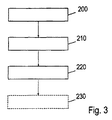
図3は、本発明による方法に対応するフローチャートを示している。第1のステップ200において、光起電力設備は、危険限界値を超える発電機70での電圧にて動作している。危険状態が検出される(ステップ210)とすぐに、発電機70での電圧は、危険限界値より下の値へと制御される(ステップ220)。この発電機電圧の制御は、発電機70の部分ストリング70a、70b、70cの直列構成を、例えば、直列接続スイッチング装置50及び並列接続スイッチング装置60を用いて、並列構成へと切り換えることにより達成される。別の仕方として、このような発電機電圧の制御は、発電機70により発生されたエネルギーを電気グリッド30へと供給するために設けられているインバータの部分である逓昇変換器の適当な制御により達成することもできる。オプションとして、この方法の更なるステップ230において、部分ストリング70a、70b、70cのうちの少なくとも1つの部分ストリングの端子のうちの少なくとも1つの端子の接地への電気接続が実施される。
FIG. 3 shows a flow chart corresponding to the method according to the invention. In the
図4は、光起電力設備についての電力曲線の軌跡を、発電機電圧Uの関数として示している。第1の曲線340は、部分ストリングの直列接続の場合における発電機についての電力Pの特性を示している。最大電力出力は、動作点300で達成され、この動作点では、発電機電圧の値UMPPは、危険限界値UGGを越えている。もし、危険状態の検出時に、発電機電圧を危険限界値UGGより下の値へと制御する必要があるならば、発電機の動作点は、例えば、危険限界値UGGの直ぐ下にある動作点330へとシフトされ、この動作点330で供給される電力は、動作点300での潜在的最大電力出力に比べて減少されている。
FIG. 4 shows the locus of the power curve for the photovoltaic installation as a function of the generator voltage U. The
もし、危険状態の検出時に、部分ストリングが直列接続から並列接続へと再構成されるならば、この結果として、第2の電力曲線350となり、この第2の電力曲線350では、ここで考察している実施例において、発電機電圧は、その軌跡の全体を通して、危険限界値UGGより下のままである。このようにして、発電機は、最大電力出力310の点で動作し続けることができ、電気エネルギーの供給が、直列接続に比較して実質的に変化しないようにすることができる。
If a partial string is reconfigured from a series connection to a parallel connection upon detection of a hazardous condition, this results in a
もし、発電機が直列接続のままであり、即ち、発電機が危険状態において動作点330で動作しているならば、インバータの電気グリッドからの分離時に、又は、電力の電気グリッドへの供給が最早可能でないような他の場合において、発電機の電力出力が零であり且つ同時に発電機電圧が危険限界値UGGより下であるような動作点を達成する必要がある。このような動作点は、発電機を短絡させることにより達成されるような短絡点320である。
If the generator is still connected in series, i.e., the generator is operating at
1・・・光起電力設備、20・・・インバータブリッジ、30・・・電気グリッド、40・・・制御装置、50・・・直列接続スイッチング装置、60・・・並列接続スイッチング装置、70・・・発電機、70a、70b、70c・・・部分ストリング、80・・・DC切断装置、110・・・短絡装置、120・・・接続ライン、130・・・接続ライン、140・・・接地装置、150・・・インバータ、200、210、220・・・方法ステップ、230・・・方法ステップ、300・・・最大電力出力に対する第1の動作点、310・・・最大電力出力に対する第2の動作点、320・・・短絡点、330・・・第3の動作点、340・・・第1の電力曲線、350・・・第2の電力曲線
DESCRIPTION OF
Claims (19)
前記インバータ(150)には、
制御装置(40)と、
前記部分ストリングを直列に接続するための直列接続スイッチング装置(50)と、
が設けられ、
前記直列接続スイッチング装置(50)は、前記インバータ(150)のハウジングまたは、前記インバータ(150)の近くに配置された別のボックスに配置され、
前記制御装置(40)は、前記直列接続スイッチング装置(50)を作動し、
前記直列接続スイッチング装置(50)は、危険状態において前記部分ストリングの直列接続を遮断することを特徴とする、光起電力設備。 In a photovoltaic facility (1) having a generator (70) having a number of partial strings (70a, 70b, 70c) and having a generator (70) connected to an inverter (150),
The inverter (150) includes
A control device (40);
A serial connection switching device (50) for connecting the partial strings in series;
Is provided ,
The series-connected switching device (50) is arranged in a housing of the inverter (150) or another box arranged near the inverter (150),
The control device (40) operates the series connection switching device (50),
The series connection switching unit (50) is characterized that you cut off the series connection of the partial strings in hazardous situations, photovoltaic facilities.
直列構成にある前記発電機(70)の部分ストリング(70a、70b、70c)を用いて、危険限界値を超える発電機電圧にて前記光起電力設備を動作させるステップと、
危険状態を検出するステップと、
前記危険状態の検出に応答して、前記直列構成を遮断することによって、前記発電機電圧を前記危険限界値より下の値へと制御するステップと、
を含むことを特徴とする方法。 In a method for limiting the voltage of a generator (70) of a photovoltaic installation in a hazardous situation using a device arranged in an inverter housing or in a separate box located near the inverter ,
Using the partial strings (70a, 70b, 70c) of the generator (70) in series configuration to operate the photovoltaic installation at a generator voltage exceeding a critical limit value;
Detecting a dangerous state;
Controlling the generator voltage to a value below the critical limit value by interrupting the series configuration in response to detection of the hazardous condition;
A method comprising the steps of:
孤立状態の発生、
前記光起電力設備(1)の電気ラインにおけるアークの検出、
前記光起電力設備(1)の電気ラインにおける接地故障の検出、
発電機切断装置の引外し、
手動緊急停止装置の引外し、
外部センサ装置の応答、
典型的には、危険状態を示す前記光起電力設備(1)に関する電気的パラメータの変動の検出、及び
データネットワークに接続されている別の光起電力設備又は別のインバータ(150)からの危険状態に関連付けられた別の信号の受信、
のうちの少なくとも1つが検出される、請求項12〜15のいずれか1項に記載の方法。 The following hazardous conditions:
The occurrence of isolation,
Arc detection in the electrical line of the photovoltaic facility (1),
Detection of a ground fault in the electrical line of the photovoltaic facility (1);
Tripping the generator cutting device,
Trip of manual emergency stop device,
Response of the external sensor device,
Typically, detection of fluctuations in electrical parameters relating to the photovoltaic installation (1) indicating a hazardous condition, and a danger from another photovoltaic installation or another inverter (150) connected to the data network. Receiving another signal associated with the condition,
16. A method according to any one of claims 12 to 15, wherein at least one of is detected.
Applications Claiming Priority (5)
| Application Number | Priority Date | Filing Date | Title |
|---|---|---|---|
| DE102010016753 | 2010-05-03 | ||
| DEDE102010016753.3 | 2010-05-03 | ||
| DE102010017746A DE102010017746A1 (en) | 2010-05-03 | 2010-07-05 | Method for limiting the generator voltage of a photovoltaic system in case of danger and photovoltaic system |
| DEDE102010017746.6 | 2010-07-05 | ||
| PCT/EP2011/057035 WO2011138314A1 (en) | 2010-05-03 | 2011-05-03 | Method for limiting the generator voltage of a photovoltaic installation in case of danger and photovoltaic installation |
Publications (2)
| Publication Number | Publication Date |
|---|---|
| JP2013530664A JP2013530664A (en) | 2013-07-25 |
| JP5830802B2 true JP5830802B2 (en) | 2015-12-09 |
Family
ID=44786290
Family Applications (2)
| Application Number | Title | Priority Date | Filing Date |
|---|---|---|---|
| JP2013508474A Pending JP2013534125A (en) | 2010-05-03 | 2011-05-03 | Method and photovoltaic installation for limiting the generator voltage of photovoltaic installations in hazardous situations |
| JP2013508471A Active JP5830802B2 (en) | 2010-05-03 | 2011-05-03 | Method and photovoltaic installation for limiting the generator voltage of photovoltaic installations in hazardous situations |
Family Applications Before (1)
| Application Number | Title | Priority Date | Filing Date |
|---|---|---|---|
| JP2013508474A Pending JP2013534125A (en) | 2010-05-03 | 2011-05-03 | Method and photovoltaic installation for limiting the generator voltage of photovoltaic installations in hazardous situations |
Country Status (6)
| Country | Link |
|---|---|
| US (2) | US20130058140A1 (en) |
| EP (2) | EP2567405B1 (en) |
| JP (2) | JP2013534125A (en) |
| CN (2) | CN102939661B (en) |
| DE (2) | DE102010017746A1 (en) |
| WO (2) | WO2011138314A1 (en) |
Families Citing this family (42)
| Publication number | Priority date | Publication date | Assignee | Title |
|---|---|---|---|---|
| DE102010017746A1 (en) * | 2010-05-03 | 2011-11-03 | Sma Solar Technology Ag | Method for limiting the generator voltage of a photovoltaic system in case of danger and photovoltaic system |
| DE102011109615A1 (en) * | 2010-12-02 | 2012-06-06 | Würth Solar Gmbh & Co. Kg | Photovoltaic module Combination of several photovoltaic modules |
| DE102011015392A1 (en) * | 2011-03-29 | 2012-10-04 | Adensis Gmbh | Photovoltaic system for electric power generation, has control apparatus for triggering control signals for simultaneous or staggered closing of switching elements, if voltage across one element exceeds first prescribed limit value |
| DE102011017362A1 (en) * | 2011-04-16 | 2012-10-18 | Adensis Gmbh | Three-switch surge protection |
| US9184594B2 (en) | 2011-06-03 | 2015-11-10 | Schneider Electric Solar Inverters Usa, Inc. | Photovoltaic voltage regulation |
| EP2587334A1 (en) * | 2011-10-24 | 2013-05-01 | Imec | Reconfigurable PV configuration |
| DE202011109688U1 (en) | 2011-12-31 | 2012-03-01 | Raik Stiebert | Safety-related design and activation of photovoltaic systems and safety-related grounding of extinguishing equipment |
| DE102012101340B4 (en) * | 2012-02-20 | 2015-11-19 | Sma Solar Technology Ag | Protection of photovoltaic modules of a photovoltaic generator against overvoltages to earth |
| US20130271888A1 (en) * | 2012-04-16 | 2013-10-17 | Sma Solar Technology Ag | Photovoltaic System and Apparatus for Operating a Photovoltaic System |
| DE102012104383B4 (en) | 2012-05-22 | 2014-03-13 | Solarworld Innovations Gmbh | Control for a photovoltaic module arrangement, photovoltaic module arrangement and inverter for a photovoltaic module arrangement |
| DE102012104384B4 (en) | 2012-05-22 | 2014-03-13 | Solarworld Innovations Gmbh | Single-pole switching unit for limiting the flow of energy in a series connection of photovoltaic modules, photovoltaic module arrangement and photovoltaic module |
| DE102012110110B4 (en) * | 2012-10-23 | 2016-12-08 | Sma Solar Technology Ag | Inverter, method for operating an inverter and power supply system with an inverter |
| EP2770539A1 (en) * | 2013-02-20 | 2014-08-27 | Total Marketing Services | Electronic management system for electricity generating cells, electricity generating system and method for electronically managing energy flow |
| US9680305B2 (en) * | 2013-03-14 | 2017-06-13 | Hiq Solar, Inc. | Implementation of fire safety shutdown for solar panels with high reliability |
| US9697961B2 (en) * | 2013-03-15 | 2017-07-04 | Solantro Semiconductor Corp. | Photovoltaic bypass switching |
| US9524832B2 (en) | 2013-03-15 | 2016-12-20 | Solantro Semiconductor Corp | Intelligent safety disconnect switching |
| US9780234B2 (en) | 2013-06-14 | 2017-10-03 | Solantro Semiconductor Corp. | Photovoltaic bypass and output switching |
| DE102013110240B4 (en) | 2013-09-17 | 2017-09-07 | Sma Solar Technology Ag | Circuit arrangement for a photovoltaic inverter for off-load relief with short-circuit switches and uses of the circuit arrangement |
| DE102013221446A1 (en) * | 2013-10-22 | 2015-04-23 | Kaco New Energy Gmbh | Inverter system and PV system |
| DE102013221444B4 (en) * | 2013-10-22 | 2019-02-07 | Kaco New Energy Gmbh | Inverter system and power supply device |
| US9799779B2 (en) * | 2013-11-08 | 2017-10-24 | The Board Of Trustees Of The University Of Illinois | Systems and methods for photovoltaic string protection |
| JP3189106U (en) | 2013-12-12 | 2014-02-20 | ティー・エス・ビー株式会社 | Solar power system |
| US9843193B2 (en) | 2014-07-30 | 2017-12-12 | Robert Getsla | Safety shutdown system for photovoltaic power generators |
| US10992255B2 (en) | 2014-10-28 | 2021-04-27 | Sunpower Corporation | Photovoltaic module or array shutdown |
| EP3248263B1 (en) | 2014-12-16 | 2019-02-20 | ABB Schweiz AG | Energy panel arrangement power dissipation |
| CN107431097B (en) | 2015-01-28 | 2020-02-14 | Abb瑞士股份有限公司 | Energy panel arrangement closure |
| US10404060B2 (en) | 2015-02-22 | 2019-09-03 | Abb Schweiz Ag | Photovoltaic string reverse polarity detection |
| US9812869B2 (en) * | 2016-03-21 | 2017-11-07 | Solarcity Corporation | Rapid shutdown and safety disconnect for hybrid PV systems |
| DE102016115295A1 (en) | 2016-08-17 | 2018-02-22 | Sma Solar Technology Ag | Separator for a photovoltaic string |
| KR101712823B1 (en) * | 2016-08-18 | 2017-03-22 | 주식회사 광명전기 | Photovoltaic solar connection board having bypass function for fire prevention |
| CN106330090B (en) * | 2016-10-17 | 2018-05-22 | 中国葛洲坝集团电力有限责任公司 | A kind of intelligent temperature control photovoltaic array system |
| DE102016125219B4 (en) * | 2016-12-21 | 2019-01-17 | Sma Solar Technology Ag | Circuit for limiting voltage in a photovoltaic field, photovoltaic field and voltage limiting method |
| DE102017102771A1 (en) * | 2017-02-13 | 2018-08-16 | Sma Solar Technology Ag | Method for determining the maximum possible power of a PV system and PV system |
| US10672918B2 (en) * | 2017-07-19 | 2020-06-02 | Solantro Semiconductor Corp. | Photovoltaic panel rapid shutdown and recovery |
| DE102017007024A1 (en) * | 2017-07-25 | 2019-01-31 | Kostal Industrie Elektrik Gmbh | Photovoltaic inverter assembly and method of operating such |
| CN107505877A (en) * | 2017-09-25 | 2017-12-22 | 国网山东省电力公司莱阳市供电公司 | A kind of intelligent photovoltaic electricity generation system protector |
| DE102018108472A1 (en) * | 2018-04-10 | 2019-10-10 | Sma Solar Technology Ag | Photovoltaic power generation plant, supply line for a power plant, mating plug and inverter |
| DE102018219293A1 (en) * | 2018-11-12 | 2020-05-14 | Kaco New Energy Gmbh | Inverter |
| CN109245711B (en) * | 2018-11-26 | 2020-02-28 | 海宁昱能电子有限公司 | Photovoltaic system safety protection equipment |
| DE102020102399A1 (en) * | 2020-01-31 | 2021-08-05 | Eaton Intelligent Power Limited | CIRCUIT PROTECTION DEVICE AND SYSTEM WITH POWER SUPPLY CONVERSION AND CONTROL FOR DC LOADS |
| DE102020129918A1 (en) | 2020-11-12 | 2022-05-12 | Sma Solar Technology Ag | Device and method for grounding a DC voltage network |
| CN114006416A (en) * | 2021-12-28 | 2022-02-01 | 北京思凌科半导体技术有限公司 | Power supply output power configuration system |
Family Cites Families (48)
| Publication number | Priority date | Publication date | Assignee | Title |
|---|---|---|---|---|
| US4333136A (en) * | 1979-11-26 | 1982-06-01 | Baker Richard H | Solar powered automatic turn-on control (SPA-TOC) unit and method |
| JPH07177652A (en) * | 1993-12-17 | 1995-07-14 | Canon Inc | Solar beam power generation system and protective system therefor |
| JP3271730B2 (en) * | 1994-04-28 | 2002-04-08 | キヤノン株式会社 | Power generation system charge control device |
| JPH09182279A (en) * | 1995-10-26 | 1997-07-11 | Nitto Kogyo Kk | Short circuit detector for photovoltaic power generation system |
| JP3700809B2 (en) * | 1997-09-29 | 2005-09-28 | 積水樹脂株式会社 | Solar cell device |
| JP2000269531A (en) * | 1999-01-14 | 2000-09-29 | Canon Inc | Solar battery module, building material therewith envelope thereof and photovoltaic power generation device |
| JP3469807B2 (en) * | 1999-03-24 | 2003-11-25 | 鐘淵化学工業株式会社 | Solar cell power generation device, wiring device for the device, and wiring structure |
| JP2001068706A (en) * | 1999-08-25 | 2001-03-16 | Sanyo Electric Co Ltd | Solar cell device |
| US6593520B2 (en) * | 2000-02-29 | 2003-07-15 | Canon Kabushiki Kaisha | Solar power generation apparatus and control method therefor |
| JP2004334704A (en) * | 2003-05-09 | 2004-11-25 | Canon Inc | Power converter, its control method, and photovoltaic generator |
| US7016793B2 (en) * | 2003-10-01 | 2006-03-21 | General Electric Company | Method and apparatus for anti-islanding protection of distributed generations |
| WO2005094230A2 (en) * | 2004-03-22 | 2005-10-13 | The Regents Of The University Of California | Hollow nanocrystals and method of making |
| JP4101212B2 (en) * | 2004-06-29 | 2008-06-18 | シャープ株式会社 | Power circuit |
| US8204709B2 (en) * | 2005-01-18 | 2012-06-19 | Solar Sentry Corporation | System and method for monitoring photovoltaic power generation systems |
| DE102005018173B4 (en) | 2005-04-19 | 2009-05-14 | Swiontek, Karl, Dipl.-Ing. | Switching device for safe interruption of operation of photovoltaic systems |
| DE102006023563B4 (en) * | 2006-05-19 | 2020-09-10 | Kostal Industrie Elektrik Gmbh | Photovoltaic system |
| DE102006060815B4 (en) | 2006-09-21 | 2013-05-29 | Solarworld Innovations Gmbh | Solar power generation plant |
| JP2008228558A (en) * | 2006-11-30 | 2008-09-25 | Beijing Hi-Tech Wealth Investment & Development Co Ltd | Method, arrangement, and system of power supply using photoelectric cell |
| US8816535B2 (en) * | 2007-10-10 | 2014-08-26 | Solaredge Technologies, Ltd. | System and method for protection during inverter shutdown in distributed power installations |
| US7772716B2 (en) * | 2007-03-27 | 2010-08-10 | Newdoll Enterprises Llc | Distributed maximum power point tracking system, structure and process |
| DE102007032605A1 (en) | 2007-07-11 | 2009-02-05 | Robert Maier | Fotovoltaikanlage |
| US7768751B2 (en) * | 2008-01-29 | 2010-08-03 | Advanced Energy Industries, Inc. | System and method for ground fault detection and interruption |
| FR2923653B1 (en) * | 2007-11-08 | 2009-11-27 | Harald Hauf | OPERATING METHOD AND DEVICE FOR CONTROLLING AN ENERGY PLANT WITH PHOTOVOLTAIC MODULES. |
| US8018748B2 (en) * | 2007-11-14 | 2011-09-13 | General Electric Company | Method and system to convert direct current (DC) to alternating current (AC) using a photovoltaic inverter |
| CN101933209B (en) * | 2007-12-05 | 2015-10-21 | 太阳能安吉有限公司 | Release mechanism in distributed electrical power apparatus, to wake up and method for closing |
| DE102008014129B4 (en) * | 2008-03-13 | 2009-12-31 | Moeller Gmbh | Protection device for solar panels |
| EP2104200B1 (en) * | 2008-03-22 | 2019-02-27 | SMA Solar Technology AG | Method for controlling a multi-string inverter for photovoltaic systems |
| DE102008021654B3 (en) * | 2008-04-30 | 2009-12-10 | Insta Elektro Gmbh | Photovoltaic system operating method, involves analyzing temporal lapse of voltage value to determine operational voltage fluctuations and voltage modulations for data transfer from internal control unit to central control unit |
| US9048353B2 (en) * | 2008-07-01 | 2015-06-02 | Perfect Galaxy International Limited | Photovoltaic DC/DC micro-converter |
| WO2010002960A1 (en) * | 2008-07-01 | 2010-01-07 | Satcon Technology Corporation | Photovoltaic dc/dc micro-converter |
| DE102008039205A1 (en) | 2008-08-22 | 2010-04-22 | EPROTECH Reimann e.K. Jürgen Reimann | Device and method for monitoring individual photovoltaic modules of a photovoltaic system |
| DE102008050402A1 (en) * | 2008-10-04 | 2010-04-08 | Diehl Ako Stiftung & Co. Kg | Circuit arrangement with a boost converter and inverter circuit with such a circuit arrangement |
| ES2338088B8 (en) * | 2008-10-30 | 2011-08-04 | Asea Brown Boveri, S.A | SYSTEM AND METHOD OF OPTIMIZATION OF ENERGY IN PHOTOVOLTAIC GENERATORS. |
| WO2010078303A2 (en) * | 2008-12-29 | 2010-07-08 | Atonometrics, Inc. | Electrical safety shutoff system and devices for photovoltaic modules |
| DE102009019831A1 (en) * | 2009-05-04 | 2010-11-11 | Voltwerk Electronics Gmbh | circuitry |
| DE102009032288A1 (en) * | 2009-07-09 | 2011-01-13 | Kostal Industrie Elektrik Gmbh | photovoltaic system |
| EP2296244B1 (en) * | 2009-08-06 | 2015-02-18 | SMA Solar Technology AG | Method and device for connecting at least one string of a photovoltaic assembly with an inverter |
| US20110090607A1 (en) * | 2009-10-20 | 2011-04-21 | Luebke Charles J | String and system employing direct current electrical generating modules and a number of string protectors |
| JP2011120449A (en) * | 2009-10-29 | 2011-06-16 | Sanyo Electric Co Ltd | Power generation system, control device, and switching circuit |
| KR101097260B1 (en) * | 2009-12-15 | 2011-12-22 | 삼성에스디아이 주식회사 | Grid-connected energy storage system and method for controlling grid-connected energy storage system |
| US9042145B2 (en) * | 2010-01-29 | 2015-05-26 | Platinum Gmbh | Circuit configuration with a step-up converter, and inverter circuit having such a circuit configuration |
| DE102010006124B4 (en) * | 2010-01-29 | 2015-04-09 | Platinum Gmbh | Circuit arrangement with a boost converter and inverter circuit with such a circuit arrangement |
| DE102010012294B4 (en) * | 2010-03-23 | 2012-04-26 | Adensis Gmbh | Photovoltaic system with potential reduction |
| DE102010017746A1 (en) * | 2010-05-03 | 2011-11-03 | Sma Solar Technology Ag | Method for limiting the generator voltage of a photovoltaic system in case of danger and photovoltaic system |
| US20120050924A1 (en) * | 2010-08-24 | 2012-03-01 | Sanyo Electric Co., Ltd. | Current collecting box for photovoltaic power generation |
| DE102010055550A1 (en) * | 2010-12-22 | 2012-06-28 | Sma Solar Technology Ag | Inverter, power plant and method of operating a power plant |
| US8547669B2 (en) * | 2011-01-12 | 2013-10-01 | Schneider Electric USA, Inc. | Arc fault mitigation for photovoltaic systems |
| US9373964B2 (en) * | 2012-05-16 | 2016-06-21 | General Electric Company | Optimized control of a power converter in response to load conditions |
-
2010
- 2010-07-05 DE DE102010017746A patent/DE102010017746A1/en not_active Ceased
- 2010-07-05 DE DE102010017747A patent/DE102010017747A1/en not_active Ceased
-
2011
- 2011-05-03 CN CN201180029268.2A patent/CN102939661B/en active Active
- 2011-05-03 EP EP11717637.0A patent/EP2567405B1/en active Active
- 2011-05-03 WO PCT/EP2011/057035 patent/WO2011138314A1/en active Application Filing
- 2011-05-03 JP JP2013508474A patent/JP2013534125A/en active Pending
- 2011-05-03 JP JP2013508471A patent/JP5830802B2/en active Active
- 2011-05-03 EP EP11718706.2A patent/EP2567406B1/en active Active
- 2011-05-03 CN CN201180029266.3A patent/CN102939660B/en active Active
- 2011-05-03 WO PCT/EP2011/057043 patent/WO2011138319A1/en active Application Filing
-
2012
- 2012-11-02 US US13/667,532 patent/US20130058140A1/en not_active Abandoned
- 2012-11-02 US US13/667,607 patent/US8837098B2/en active Active
Also Published As
| Publication number | Publication date |
|---|---|
| DE102010017746A1 (en) | 2011-11-03 |
| CN102939661B (en) | 2016-03-16 |
| JP2013534125A (en) | 2013-08-29 |
| EP2567405A1 (en) | 2013-03-13 |
| WO2011138314A1 (en) | 2011-11-10 |
| JP2013530664A (en) | 2013-07-25 |
| US8837098B2 (en) | 2014-09-16 |
| WO2011138319A1 (en) | 2011-11-10 |
| US20130058140A1 (en) | 2013-03-07 |
| CN102939660B (en) | 2016-10-05 |
| EP2567406B1 (en) | 2015-07-29 |
| CN102939660A (en) | 2013-02-20 |
| EP2567405B1 (en) | 2015-09-16 |
| CN102939661A (en) | 2013-02-20 |
| US20130057989A1 (en) | 2013-03-07 |
| DE102010017747A1 (en) | 2011-11-03 |
| EP2567406A1 (en) | 2013-03-13 |
Similar Documents
| Publication | Publication Date | Title |
|---|---|---|
| JP5830802B2 (en) | Method and photovoltaic installation for limiting the generator voltage of photovoltaic installations in hazardous situations | |
| KR101496199B1 (en) | Solar cell module having function for breaking of power and control method therefor | |
| US9620956B2 (en) | Socket for a solar panel with a protective circuit | |
| US9070797B2 (en) | Photovoltaic installation | |
| WO2015087638A1 (en) | Solar photovoltaic system | |
| EP2756525B1 (en) | Safety device for a photovoltaic system | |
| JP5590475B2 (en) | Reverse current sensor | |
| EP2721711B1 (en) | Inverter with monitoring of the moisture state and method for operating an inverter | |
| WO2010078303A2 (en) | Electrical safety shutoff system and devices for photovoltaic modules | |
| EP2752881B1 (en) | Shutdown method for photovoltaic system | |
| WO2011028457A2 (en) | Systems and methods for an enhanced watchdog in solar module installations | |
| JP6042682B2 (en) | Solar power system | |
| JP2014509176A (en) | Protection device for photovoltaic system | |
| JP6486115B2 (en) | Solar power system | |
| US9735777B2 (en) | Disconnection of solar modules | |
| US10388802B2 (en) | System and method for synchronized rapid shutdown of electrical devices | |
| CN204835513U (en) | Voltage type arc light protection device | |
| JP7176611B2 (en) | Solar power system | |
| JP2017079568A (en) | Photovoltaic power generation system | |
| CN217741960U (en) | Fire-fighting emergency lighting system | |
| CN116435966A (en) | Photovoltaic protection device, inverter and photovoltaic power generation system | |
| CN104115281B (en) | The cut-out of solar energy module | |
| KR20180046337A (en) | Power distributor, control board and distribution board having function of cut-off and recovery by stages against earthquake and optimal operation | |
| ITTV20130015A1 (en) | METHOD AND AUTOMATIC SYSTEM OF CURRENT INTERRUPTION CONFIGURED TO ISOLATE ELECTRICALLY, IN A SELECTIVE WAY, OF PHOTOVOLTAIC PANELS IN A STRING OF PHOTOVOLTAIC PANELS |
Legal Events
| Date | Code | Title | Description |
|---|---|---|---|
| A621 | Written request for application examination |
Free format text: JAPANESE INTERMEDIATE CODE: A621 Effective date: 20140430 |
|
| A977 | Report on retrieval |
Free format text: JAPANESE INTERMEDIATE CODE: A971007 Effective date: 20141226 |
|
| A131 | Notification of reasons for refusal |
Free format text: JAPANESE INTERMEDIATE CODE: A131 Effective date: 20150106 |
|
| A521 | Request for written amendment filed |
Free format text: JAPANESE INTERMEDIATE CODE: A523 Effective date: 20150402 |
|
| TRDD | Decision of grant or rejection written | ||
| A01 | Written decision to grant a patent or to grant a registration (utility model) |
Free format text: JAPANESE INTERMEDIATE CODE: A01 Effective date: 20150929 |
|
| A61 | First payment of annual fees (during grant procedure) |
Free format text: JAPANESE INTERMEDIATE CODE: A61 Effective date: 20151006 |
|
| R150 | Certificate of patent or registration of utility model |
Ref document number: 5830802 Country of ref document: JP Free format text: JAPANESE INTERMEDIATE CODE: R150 |
|
| R250 | Receipt of annual fees |
Free format text: JAPANESE INTERMEDIATE CODE: R250 |
|
| R250 | Receipt of annual fees |
Free format text: JAPANESE INTERMEDIATE CODE: R250 |
|
| R250 | Receipt of annual fees |
Free format text: JAPANESE INTERMEDIATE CODE: R250 |
|
| R250 | Receipt of annual fees |
Free format text: JAPANESE INTERMEDIATE CODE: R250 |
|
| R250 | Receipt of annual fees |
Free format text: JAPANESE INTERMEDIATE CODE: R250 |
|
| R250 | Receipt of annual fees |
Free format text: JAPANESE INTERMEDIATE CODE: R250 |