JP5806937B2 - System and method for mechanical closure of a wound - Google Patents
System and method for mechanical closure of a wound Download PDFInfo
- Publication number
- JP5806937B2 JP5806937B2 JP2011538707A JP2011538707A JP5806937B2 JP 5806937 B2 JP5806937 B2 JP 5806937B2 JP 2011538707 A JP2011538707 A JP 2011538707A JP 2011538707 A JP2011538707 A JP 2011538707A JP 5806937 B2 JP5806937 B2 JP 5806937B2
- Authority
- JP
- Japan
- Prior art keywords
- instrument
- wound
- elongated
- connector
- attached
- Prior art date
- Legal status (The legal status is an assumption and is not a legal conclusion. Google has not performed a legal analysis and makes no representation as to the accuracy of the status listed.)
- Expired - Fee Related
Links
Images


Classifications
-
- A—HUMAN NECESSITIES
- A61—MEDICAL OR VETERINARY SCIENCE; HYGIENE
- A61B—DIAGNOSIS; SURGERY; IDENTIFICATION
- A61B17/00—Surgical instruments, devices or methods, e.g. tourniquets
- A61B17/08—Wound clamps or clips, i.e. not or only partly penetrating the tissue ; Devices for bringing together the edges of a wound
- A61B17/085—Wound clamps or clips, i.e. not or only partly penetrating the tissue ; Devices for bringing together the edges of a wound with adhesive layer
-
- A—HUMAN NECESSITIES
- A61—MEDICAL OR VETERINARY SCIENCE; HYGIENE
- A61B—DIAGNOSIS; SURGERY; IDENTIFICATION
- A61B17/00—Surgical instruments, devices or methods, e.g. tourniquets
-
- A—HUMAN NECESSITIES
- A61—MEDICAL OR VETERINARY SCIENCE; HYGIENE
- A61M—DEVICES FOR INTRODUCING MEDIA INTO, OR ONTO, THE BODY; DEVICES FOR TRANSDUCING BODY MEDIA OR FOR TAKING MEDIA FROM THE BODY; DEVICES FOR PRODUCING OR ENDING SLEEP OR STUPOR
- A61M1/00—Suction or pumping devices for medical purposes; Devices for carrying-off, for treatment of, or for carrying-over, body-liquids; Drainage systems
- A61M1/90—Negative pressure wound therapy devices, i.e. devices for applying suction to a wound to promote healing, e.g. including a vacuum dressing
- A61M1/91—Suction aspects of the dressing
- A61M1/912—Connectors between dressing and drainage tube
-
- A—HUMAN NECESSITIES
- A61—MEDICAL OR VETERINARY SCIENCE; HYGIENE
- A61M—DEVICES FOR INTRODUCING MEDIA INTO, OR ONTO, THE BODY; DEVICES FOR TRANSDUCING BODY MEDIA OR FOR TAKING MEDIA FROM THE BODY; DEVICES FOR PRODUCING OR ENDING SLEEP OR STUPOR
- A61M27/00—Drainage appliance for wounds or the like, i.e. wound drains, implanted drains
-
- A—HUMAN NECESSITIES
- A61—MEDICAL OR VETERINARY SCIENCE; HYGIENE
- A61B—DIAGNOSIS; SURGERY; IDENTIFICATION
- A61B17/00—Surgical instruments, devices or methods, e.g. tourniquets
- A61B2017/00535—Surgical instruments, devices or methods, e.g. tourniquets pneumatically or hydraulically operated
- A61B2017/00561—Surgical instruments, devices or methods, e.g. tourniquets pneumatically or hydraulically operated creating a vacuum
-
- A—HUMAN NECESSITIES
- A61—MEDICAL OR VETERINARY SCIENCE; HYGIENE
- A61B—DIAGNOSIS; SURGERY; IDENTIFICATION
- A61B17/00—Surgical instruments, devices or methods, e.g. tourniquets
- A61B17/08—Wound clamps or clips, i.e. not or only partly penetrating the tissue ; Devices for bringing together the edges of a wound
- A61B2017/081—Tissue approximator
-
- A—HUMAN NECESSITIES
- A61—MEDICAL OR VETERINARY SCIENCE; HYGIENE
- A61B—DIAGNOSIS; SURGERY; IDENTIFICATION
- A61B17/00—Surgical instruments, devices or methods, e.g. tourniquets
- A61B17/08—Wound clamps or clips, i.e. not or only partly penetrating the tissue ; Devices for bringing together the edges of a wound
- A61B17/085—Wound clamps or clips, i.e. not or only partly penetrating the tissue ; Devices for bringing together the edges of a wound with adhesive layer
- A61B2017/086—Wound clamps or clips, i.e. not or only partly penetrating the tissue ; Devices for bringing together the edges of a wound with adhesive layer having flexible threads, filaments, laces or wires, e.g. parallel threads, extending laterally from a strip, e.g. for tying to opposing threads extending from a similar strip
-
- A—HUMAN NECESSITIES
- A61—MEDICAL OR VETERINARY SCIENCE; HYGIENE
- A61B—DIAGNOSIS; SURGERY; IDENTIFICATION
- A61B17/00—Surgical instruments, devices or methods, e.g. tourniquets
- A61B17/30—Surgical pincettes without pivotal connections
- A61B2017/306—Surgical pincettes without pivotal connections holding by means of suction
- A61B2017/308—Surgical pincettes without pivotal connections holding by means of suction with suction cups
-
- A—HUMAN NECESSITIES
- A61—MEDICAL OR VETERINARY SCIENCE; HYGIENE
- A61M—DEVICES FOR INTRODUCING MEDIA INTO, OR ONTO, THE BODY; DEVICES FOR TRANSDUCING BODY MEDIA OR FOR TAKING MEDIA FROM THE BODY; DEVICES FOR PRODUCING OR ENDING SLEEP OR STUPOR
- A61M1/00—Suction or pumping devices for medical purposes; Devices for carrying-off, for treatment of, or for carrying-over, body-liquids; Drainage systems
- A61M1/90—Negative pressure wound therapy devices, i.e. devices for applying suction to a wound to promote healing, e.g. including a vacuum dressing
- A61M1/91—Suction aspects of the dressing
- A61M1/916—Suction aspects of the dressing specially adapted for deep wounds
-
- A—HUMAN NECESSITIES
- A61—MEDICAL OR VETERINARY SCIENCE; HYGIENE
- A61M—DEVICES FOR INTRODUCING MEDIA INTO, OR ONTO, THE BODY; DEVICES FOR TRANSDUCING BODY MEDIA OR FOR TAKING MEDIA FROM THE BODY; DEVICES FOR PRODUCING OR ENDING SLEEP OR STUPOR
- A61M1/00—Suction or pumping devices for medical purposes; Devices for carrying-off, for treatment of, or for carrying-over, body-liquids; Drainage systems
- A61M1/90—Negative pressure wound therapy devices, i.e. devices for applying suction to a wound to promote healing, e.g. including a vacuum dressing
- A61M1/91—Suction aspects of the dressing
- A61M1/918—Suction aspects of the dressing for multiple suction locations
Description
本発明は、2008年12月2日に出願され、参照することにより全てここで引用された米国特許出願番号第12/326,589号の優先権の利益を主張する。 The present invention claims the benefit of priority of US patent application Ser. No. 12 / 326,589, filed Dec. 2, 2008, all hereby incorporated by reference.
本開示は、創傷の治療のための器具及び方法、特に、機械的な力及び減圧治療を可能にする器具及び方法に関する。 The present disclosure relates to devices and methods for the treatment of wounds, and more particularly to devices and methods that allow mechanical force and reduced pressure treatments.
減圧、又は真空アシスト治療が、様々な要因により、多くの様々な解剖学的な部位で創傷の回復を改善するために効果的である。一般に、減圧治療は、創傷部位に配置された多孔質材料を有する。メンブレン又はドレープが、多孔質材料の上方に配置され、創傷領域に空圧シールを与え、多孔質材料に負圧が適用されて、創傷部位に減圧を与える。 Depressurization, or vacuum assisted therapy, is effective to improve wound healing at many different anatomical sites due to various factors. Generally, reduced pressure treatment has a porous material placed at the wound site. A membrane or drape is placed over the porous material to provide a pneumatic seal in the wound area and a negative pressure is applied to the porous material to provide a reduced pressure at the wound site.
組織伸長システムは、創傷の閉合を補助する。このような伸長システムは、創傷の周囲の組織に機械的な力を与え、時間をかけて創傷の周縁を近置し得る。 The tissue extension system assists in wound closure. Such an extension system can provide mechanical force to the tissue surrounding the wound and bring the wound periphery closer over time.
特定の実施例によれば、減圧源に取り付けられるよう構成された少なくとも1の第1の開口部及び第1の本体を通って少なくとも部分的に延びて少なくとも1の開口部と液通する少なくとも1の流路を具える第1の本体を具える創傷治療器具が提供される。さらに、この器具は、2又はそれ以上の細長部を具えるており、それぞれが第1の本体に取り付けられ、第1の本体から様々な方向に延びており、第1の本体に対して調節可能な長さを有する。 According to certain embodiments, at least one first opening configured to be attached to a reduced pressure source and at least one extending at least partially through the first body and in fluid communication with the at least one opening. There is provided a wound treatment device comprising a first body comprising a plurality of channels. In addition, the device includes two or more elongate portions, each attached to the first body and extending from the first body in various directions, adjusted relative to the first body. Have a possible length.
特定の実施例によれば、創傷を治療するための方法が提供されており、創傷の周囲の2又はそれ以上の場所の組織に2又はそれ以上の細長部を機械的に結合するステップであって、2又はそれ以上の細長部が、減圧源に取り付けるよう構成した少なくとも1の第1の開口部及び第1の本体を通して少なくとも部分的に延びて少なくとも1の開口部する少なくとも1の流路を具える第1の本体に取り付けられるステップを具える。さらに、この方法は、2又はそれ以上の細長部に張力を発生させて、創傷の周囲の2又はそれ以上の場所の組織を一緒に引き寄せるステップを有する。 According to certain embodiments, a method for treating a wound is provided, comprising mechanically coupling two or more elongated portions to tissue at two or more locations surrounding the wound. And at least one first opening configured to attach to the reduced pressure source and at least one flow path extending at least partially through the first body and having at least one opening. Comprising a step attached to a first body comprising. In addition, the method includes the step of creating tension in two or more elongates to draw the tissue in two or more locations around the wound together.
特定の実施例によれば、実質的に硬質の材料の本体を有する第1の本体を具える創傷治療器具が提供される。さらに、この器具は、2又はそれ以上の細長部であって、それぞれが、第1の本体に取り付けられ、異なる方向に第1の本体から延びており、第1の本体に対して調整可能な長さを有する細長部を具える。また、この器具は、2又はそれ以上のコネクタを機械的に結合させるための接着剤であって、それぞれが、2又はそれ以上の細長部の1つ、及び創傷を囲む組織に付けられた接着剤を具える。 According to certain embodiments, a wound care device is provided that includes a first body having a body of substantially rigid material. Further, the instrument is two or more elongate sections, each attached to the first body and extending from the first body in a different direction and adjustable relative to the first body. It has an elongated portion having a length. The device is also an adhesive for mechanically joining two or more connectors, each of which is attached to one of the two or more elongated portions and the tissue surrounding the wound. Contains medicine.
特定の実施例によれば、創傷を治療するための方法が提供されており、接着剤を用いて創傷の周囲の2又はそれ以上の場所の組織に2又はそれ以上の細長部を機械的に結合するステップであって、2又はそれ以上の細長部が第1の材料本体に取り付けられるステップを具える。さらに、この方法は、2又はそれ以上の細長部に張力を発生させて、創傷の周囲の2又はそれ以上の場所の組織を一緒に引き寄せるステップを具える。 According to certain embodiments, a method for treating a wound is provided, wherein an adhesive is used to mechanically place two or more elongated portions in tissue at two or more locations around the wound. Joining, comprising the step of attaching two or more elongate portions to the first material body. In addition, the method includes the step of creating tension in the two or more elongated portions to draw the tissue in two or more locations around the wound together.
ここで、添付図面に特定の例が示された本開示に係る特定の典型的な実施例を詳細に説明することとする。可能な限り、同一又は類似するパーツを参照するのに、図面を通して同じ符号を使用することとする。 Reference will now be made in detail to certain exemplary embodiments according to the present disclosure, examples of which are illustrated in the accompanying drawings. Wherever possible, the same reference numbers will be used throughout the drawings to refer to the same or like parts.
本開示は、機械的な力を与えて、創傷の閉合、又は少なくとも部分的な閉合を補助するよう使用され得る創傷治療器具に関する。ある実施例では、周囲の皮膚又は他の組織を損傷させることなしに、近置する創傷の周縁に向く機械的な力を与えるよう本開示の器具を構成し得る。ある実施例では、皮膚又は他の組織を貫通させることなしに、機械的な力をかける。特定の実施例では、器具が、減圧治療とともに、近置する創傷の周縁に向く機械的な力を与える。様々な実施例では、器具を使用して、様々な創傷の形状及び様々な解剖学的部位を治療し得る。 The present disclosure relates to a wound treatment device that can be used to provide mechanical force to assist in the closure or at least partial closure of a wound. In certain embodiments, the device of the present disclosure may be configured to provide a mechanical force toward the perimeter of an adjacent wound without damaging surrounding skin or other tissue. In some embodiments, mechanical force is applied without penetrating the skin or other tissue. In certain embodiments, the instrument, along with reduced pressure treatment, provides a mechanical force toward the peripheral edge of the adjacent wound. In various embodiments, the instrument can be used to treat various wound shapes and various anatomical sites.
本出願では、単数形の使用は、特に断らない限り複数を含んでいる。本出願では、「又は」の使用は、特に断らない限り「及び/又は」を意味する。さらに、「含んでいる」という用語の使用は、「含む」及び「含まれている」といった他の形式とともに、限定されるものではない。さらに、「構成要素」又は「部品」といった用語は、特に断らない限り、1つのユニットを具える構成要素及び部品及び2以上のサブユニットを具える構成要素及び部品の双方を含むものである。また、「部分」という用語の使用は、半分又は一部を含んでいる。 In this application, the use of the singular includes the plural unless specifically stated otherwise. In this application, the use of “or” means “and / or” unless stated otherwise. Further, use of the term “including” is not limited to other forms such as “included” and “included”. Further, the terms “component” or “part” are intended to include both components and parts comprising one unit and components and parts comprising two or more subunits, unless otherwise specified. Also, the use of the term “part” includes half or part.
ここで使用される節の見出しは、単に構成上の目的とするものであり、開示された発明を限定するものとして解釈すべきではない。本出願で引用される、特許、特許出願、論説、書籍、及び、論文を含むがこれらに限定されない全ての文献、又は文献の部分は、いかなる目的に対しても、参照することにより全てここで明示的に引用されている。 The section headings used herein are for organizational purposes only and are not to be construed as limiting the disclosed invention. All references, or parts of references, including but not limited to patents, patent applications, editorials, books, and articles cited in this application are hereby incorporated by reference for all purposes. It is explicitly quoted.
ここで使用する「減圧」という用語は、一般に、治療を受ける組織部位の周囲圧力よりも低い圧力に関する。大部分のケースにおいて、このような減圧は、患者が居る大気圧よりも低いであろう。代替的に、減圧を組織部位の組織に関する静水圧よりも低くし得る。減圧は、管の中及び組織部位の領域での流体の流れを最初に発生する。組織部位の周りの静水圧が所望の減圧に近づくと、流れが低下し、その後減圧が維持される。他のものを示さない限り、ここで言及する圧力の値は、ゲージ圧である。 As used herein, the term “reduced pressure” generally relates to a pressure that is lower than the ambient pressure at the tissue site being treated. In most cases, such reduced pressure will be lower than the atmospheric pressure at which the patient is. Alternatively, the reduced pressure can be lower than the hydrostatic pressure for the tissue at the tissue site. Depressurization initially generates fluid flow in the tube and in the region of the tissue site. As the hydrostatic pressure around the tissue site approaches the desired reduced pressure, the flow decreases and then the reduced pressure is maintained. Unless otherwise indicated, the pressure values referred to herein are gauge pressures.
ここで使用する「流体」という用語は、一般に、気体又は液体に関するが、ゲル、コロイド、及び発泡体といったこれらに限定されない他の流動的な材料も含む。 The term “fluid” as used herein generally relates to gases or liquids, but also includes other fluid materials such as but not limited to gels, colloids, and foams.
多くのタイプの創傷において、回復時間を改善し合併症を減らすのに、減圧治療が効果的であるが、いくつかのケースでは、付加的な治療が結果を改善するのに役立つ。例えば、より大きな創傷では、創傷全体を覆う不十分な上方の真皮、表皮、及び/又は皮下組織を有する場合がある。このようなケースでは、植皮又は他の再建処置を使用して創傷を覆う。特定の実施例では、ここで説明する器具を使用して、機械的な力及び減圧を与え、創傷の閉合を補助することができ、植皮又は他の再建処置なしに創傷を閉合し回復する。特定の実施例では、ここで説明された器具を使用して、機械的な力及び減圧治療を与え、創傷の閉合を補助し、植皮又は他の処置又は治療の前に、これらと同時に、及び/又はこれらの後に、器具を使用し得る。 In many types of wounds, reduced pressure treatment is effective in improving recovery time and reducing complications, but in some cases, additional treatments can help improve results. For example, larger wounds may have insufficient upper dermis, epidermis, and / or subcutaneous tissue covering the entire wound. In such cases, a skin graft or other reconstruction procedure is used to cover the wound. In certain embodiments, the devices described herein can be used to provide mechanical force and reduced pressure to assist in the closure of the wound and to close and recover the wound without skin grafting or other reconstruction procedures. In certain examples, the devices described herein are used to provide mechanical force and reduced pressure therapy, assist in wound closure, prior to, or prior to, skin grafting or other treatment or therapy, and An instrument may be used after / or after these.
ある実施例では、ここで説明される器具を使用して、負傷及び/又は手術による外傷によって引き起こされる創傷の治療を補助し得る。さらに、一次的閉合遅延又は二次的な近置による閉合を用いて、外科的な創傷が閉合される。特定の実施例では、ここで説明される器具を使用して、機械的な力及び減圧治療を与え、一次的閉合遅延又は二次的な近置による創傷の閉合を補助し得る。さらに、特定の創傷が、手術又は外傷ではなく、糖尿病又は血管系の病気によって引き起こされる。特定の実施例では、ここで説明される器具を使用して、疾病によって引き起こされる創傷の回復を補助する。 In certain embodiments, the devices described herein may be used to assist in the treatment of wounds caused by injury and / or surgical trauma. In addition, surgical wounds are closed using primary closure delays or secondary proximity closures. In certain embodiments, the devices described herein can be used to provide mechanical force and reduced pressure therapy to assist in wound closure due to primary closure delay or secondary proximity. In addition, certain wounds are caused by diabetes or vascular disease, not surgery or trauma. In certain embodiments, the devices described herein are used to assist in healing wounds caused by disease.
多くの機械的な閉合システムが、創傷に近接する組織を把持するための鋭いフック又は返しを有する。これらのフック又は返しは、周囲の組織への機械的な力の短期的な適用に有効であるが、より長期間にわたって使用する場合、近接する組織が損傷する可能性がある。 Many mechanical closure systems have sharp hooks or barbs for grasping tissue proximate the wound. These hooks or barbs are effective for short-term application of mechanical force to the surrounding tissue, but when used over longer periods, adjacent tissue can be damaged.
さらに、従来の機械的創傷閉合器具は、減圧治療器具との使用に適合しない。ここで説明される器具は、減圧治療に適合する。特定の実施例では、ここで説明される器具により、多孔質材料の周期的な交換又は減圧治療で使用される他の処置が可能となる。 Furthermore, conventional mechanical wound closure devices are not suitable for use with reduced pressure treatment devices. The devices described herein are compatible with reduced pressure therapy. In certain embodiments, the devices described herein allow for periodic replacement of porous material or other procedures used in reduced pressure therapy.
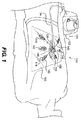
図1は、特定の典型的な実施例に係る機械的治療器具110及び減圧治療器具120を含む創傷治療器具100を示しており、図2は、図1の器具110の拡大図を示しており、特定の実施例において、患者への構成要素の適用方法を示す。以下により詳細に図示し説明するように、機械的治療器具110は、第1の本体130及び第1の本体130に取り付けられそこから延びる2又はそれ以上の細長部140を有する。細長部140は、創傷の周囲の組織又は創傷の上方の柔軟性のあるシート160に取り付けられ、創傷の周囲の組織に取り付けられるよう構成されている。細長部140を位置決めして、創傷の縁部を一緒に引っ張るような力を与えることができ、第1の本体130の締め付け機構を用いて、細長部140の長さを調節することによって、このような力を制御し得る。
FIG. 1 illustrates a
さらに、ある実施例では、器具100が減圧治療器具120を有する。図示するように、減圧治療器具120は、例えば、流路又は管124を通して機械的治療器具110に流体結合するポンプ122を有する。ある実施例では、機械的治療器具110の第1の本体130が、流体通路又は管124に結合するよう構成された流体又は吸引コネクタ126を有する。コネクタ126は、第1の本体130の下方のスペースに流体結合することができ、これにより、創傷に吸引又は減圧を与える。したがって、第1の本体130が、第1の通路124と創傷部位との間の流体結合を与え得る。上述のように、ある実施例では、創傷の周りの組織に調節可能な機械的な力を適用できる一方、減圧治療を管理し得るように、機械的治療器具110を構成し得る。
Further, in certain embodiments, the
機械的治療器具110は、様々な異なる形状及び様々な解剖学的部位の創傷の周縁に張力を与え得る。例えば、図1及び2に示すように、器具110が、細長い又は(図2に示す)略直線の創傷部位150のほぼ反対の側に延びる6つの細長部140を有する。図1及び2に示すように、細長部140は、ワイヤ、コード、又は糸といった遠位のコネクタ142に取り付けられる柔軟性のある材料で形成することができ、創傷部位150の上方の組織(例えば、皮膚)又は柔軟性のあるシート160に係合するよう構成される。ある実施例では、細長部を弾性のある又は柔軟性のある高分子材料で形成し得る。
The
上述のように、図1は、6つの細長部140を有する機械的治療器具110を示すが、細長部140の数を変えることができる。特定の実施例では、細長部140の数が、使用意図、治療される創傷の形状又は大きさ、及び/又は創傷の解剖学的部位に関連する。ある実施例では、機械的治療器具110が、少なくとも2の細長部、少なくとも3の細長部、少なくとも4の細長部、少なくとも5の細長部、少なくとも6の細長部、少なくとも7の細長部、少なくとも8の細長部を有する。様々な実施例では、治療される特定の創傷に基づいて、適切な数の細長部を選択し得る。
As described above, FIG. 1 shows a
さらに、様々な実施例では、細長部140の向き及び/又は長さを変えることができる。特定の実施例では、向き及び/又は長さが、治療される特定の創傷に基づいている。例えば、図1に示すように、3つの細長部が、細長い創傷のそれぞれの側に設けられていることで、創傷の端部を互いに引っ張り得る。しかしながら、2つのみの細長部140を使用できる場合、それぞれが創傷の反対側に配置されており、互いに創傷の周縁を引っ張る。
Further, in various embodiments, the orientation and / or length of the
特定の実施例では、より丸く及び/又は不規則な創傷について、第1の本体130に対する各細長部140の向きを選択して、周囲の組織にかかる力の方向及び大きさを制御し得る。さらに、特定の実施例では、細長部140の柔軟性により、外科医又は他の医療従事者が広範囲の大きさ及び形状を有する創傷を治療し得るように、高度の制御が可能となる。さらに、様々な実施例では、以下に詳細に示すように、より不規則又はより大きな創傷について、より細長い部分140を使用し得る。
In certain embodiments, for more round and / or irregular wounds, the orientation of each elongate 140 relative to the
様々な実施例では、第1の本体130及び細長部140が、様々な異なる構造及び/又は材料を有する。例えば、図示するように、細長部140が、細長い、柔軟性のあるワイヤ又はコードを有する。これらのワイヤ又はコードを、金属及び/又は合成又は天然高分子を含むがこれらに限定されない様々な適切な材料で形成し得る。様々な実施例では、細長部140を、編状とし、層状とし、又は一体構造とし得る。様々な実施例では、細長部140に適用される力の大きさ及び/又は選択される解剖学的部位の柔軟性の程度に基づいて、特定の材質及び寸法を選択し得る。ある実施例では、第1の本体130を、(以下の第1の本体230、830、930とともに)細長部140によって加わる張力に抗し得る硬質プラスチック又は金属といった硬質材料で作製し得る。特定の実施例では、第1の本体130の部分又は全部をより軟らかく又はより柔軟にし得る。
In various embodiments, the
上述のように、機械力を与えて創傷の閉塞を補助する一方、減圧治療を与えるよう機械的治療器具110を構成し得る。様々な実施例では、様々な減圧治療器具を使用し得る。例えば、適切な減圧治療器具が、テキサス州サンアントニオ所在のKinetic Concepts,lnc製のV.A.C.(登録商標)治療器具を有する。このような減圧治療器具は、機械的治療器具110の第1の本体130に流体結合される図1に示すポンプ122と同じような真空ポンプを有し得る。また、このような器具は、柔軟性のあるシート160を有しており、創傷部位150をカバーし、創傷を少なくとも部分的に密閉して、創傷部位に減圧治療を与えることができる。さらに、このようなシステムは、創傷部位に置かれて創傷の閉合、回復、組織の再生又は修復を促し、感染を防止又は治療し、他の利点を有する多孔質材料又は包帯剤180を有する。
As described above, the
ある実施例では、柔軟性のあるシート160が柔軟性のある高分子材料を有する。様々な実施例では、適切な高分子材料を選択し得る。様々な実施例では、材料は、顕著な刺激、免疫反応、感染リスクの増大を引き起こさない。様々な実施例では、特定の材料は、概して十分な厚さ及び不透過性を有しており、シート160の下方の創傷部位の減圧治療が可能となる。ある実施例では、コネクタ142を柔軟性のあるシート160に取り付けることができる一方、柔軟性のあるシート160が下にある皮膚又は他の組織に付けられる。したがって、様々な実施例では、機械的治療器具110によって発生する機械的な力が、少なくとも部分的にシート160を通して伝わり、これにより、特定の材料の厚さ及び物理的性質を選択してこのような物理的要求に抗する。
In some embodiments, the
ある実施例では、器具100が接着剤を有する。ここで使用し、本開示を通して使用するように、接着剤は、2つの物体の表面を互いに付着させ得る物質に関する。様々な実施例では、適切な接着剤が、組織又は器具100の他の構成要素への柔軟性のあるシート160の付着を促進し得る様々なセメント、のり、樹脂、又は他の材料を有する。ある実施例では、接着剤が感圧アクリル系接着剤を有する。様々な実施例では、結合される構造に直接的に接着剤を適用でき、又は接着剤をテープ又は他の支持基板材料に適用し得る。
In certain embodiments, the
ある実施例では、接着剤を柔軟性のあるシート160の表面に適用して、皮膚又は他の組織にシートを付着させ得る。ある実施例では、接着剤をシートの表面に適用し、シート160で包み及び/又はこれを塗布する。ある実施例では、接着剤をシート160の表面に適用して、使用のために接着剤を露出させるよう取り外し得る非接着性材料によってカバーする。特定の実施例では、接着剤を、組織にシート160を付着させるようシート160に適用される(例えば、容器内又はテープ上の)別々の構成要素として与え得る。
In some embodiments, an adhesive may be applied to the surface of the
様々な実施例では、多孔質材料180が様々な適切な材料を有する。例えば、多くの様々な包帯剤材料が、上述のV.A.C(登録商標)治療システムとともに使用するために利用し得る。このような包帯剤は、オープンセルのポリウレタンといった多孔質のオープンセルの発泡体構造を有するがこれに限定されない。様々な実施例では、様々な治療剤を含む他の材料を、本開示の器具とともに使用するために選択でき、様々な実施例では、治療される特定の創傷に基づいて特定の包帯剤を選択し得る。
In various embodiments, the
上述のように、ある実施例では、細長部140に取り付けられたコネクタ142を皮膚又は他の組織、又は創傷部位150及び包帯剤180を覆う柔軟性のあるシート160に取り付けることができる。コネクタ142についてのある典型的な構成を以下に詳細に説明する。ある実施例では、コネクタ142を、シート、皮膚、又は他の組織に貫通させずに、柔軟性のあるシート、皮膚、又は他の組織に付けるよう構成し得る。例えば、ある実施例では、コネクタ142の下面516に接着剤を配置して、皮膚に貫通させずに、コネクタ142をシート、皮膚、又は他の組織に付けることができる。ある実施例では、接着剤が、患者に柔軟性のあるシート160を付けるよう選択されるのと同じ接着剤を有する。ある実施例では、接着剤が感圧アクリル系接着剤を有し得る。ある実施例では、接着剤がシアノアクリレート系接着剤である。
As described above, in some embodiments, the
ある実施例では、コネクタ142が、細長部140と比較して拡がった少なくとも1つの大きさを有する。ある実施例では、コネクタ142が、それが付けられる細長部140よりも幅が広い。ある実施例では、コネクタ142が、その長さよりも広い表面を有し、取り付けのための大きな面を与える。
In some embodiments, the
様々な実施例では、細長部140へのコネクタ142の取り付け方法を変えることができる。ある実施例では、コネクタ142を細長部140に取り外し可能に取り付けることができる。他の実施例では、コネクタ142を取り外せないように細長部140に付けることができる。ある実施例では、コネクタ142を、細長部140を形成する材料と同じ部品で形成し得る。特定の実施例では、コネクタ142を、別の材料片で形成し得るが、溶接、化学結合、又は接着剤で取り外せないよう付けることができる。
In various embodiments, the manner in which the
ある実施例では、図2に示すように、機械的治療器具110の少なくとも部分が柔軟性のあるシート160の上面に付けられた状態で、柔軟性のあるシート160を創傷部位150の上方に付けることができる。特定の実施例では、創傷が初めに洗浄され、他の準備プロセスが実施される。次に、創傷を処理した後に、多孔質材料180又は包帯剤が選択され、創傷部位150に置かれる前に適切な大きさにカットされる。そして、包帯剤を創傷に置いた後に、創傷の周縁の上方にあるシート160の端部が十分に離れて減圧治療を実施し得るよう密閉を形成するように、柔軟性のあるシート160を創傷部位150の上方に付ける。
In one embodiment, as shown in FIG. 2, the
包帯剤及びシートを創傷の上方に置いた後に、機械的治療器具110の第1の本体130をシート160に付ける。ある実施例では、シート160が予め形成された開口又は流路を有しており、機械的治療器具を取り付けることができる。ある実施例では、第1の本体130及びシート160を、すでに組み立てられた1つのユニットとして作製及び/又は割り当て得る。ある実施例では、外科医は、開口が無い又は第1の本体130用の予め形成されたアタッチメント有するシートを使用し得るが、開口を作製し、コネクタ142及び/又はシート160に付けるよう使用されるような接着剤を用いて第1の本体130を付ける。ある実施例では、シート160が、予め形成された通路を通してシート160に付けられる管状部材を有しており、このような管状部材に付けて下方の創傷との第1の液通を与えるよう構成し得る。
After the dressing and sheet are placed over the wound, the
第1の本体130をシート160に付けた後に、コネクタ142をシート160上に配置し得る。上述のように、接着剤を用いてコネクタ142をシート160に付けることができ、コネクタ142の下面516をシートに付ける。したがって、シート160が患者の皮膚又は他の組織に接着された状態で、及び機械的治療器具110がシート160に付いた状態で、細長部140に発生する力が患者の組織に伝わることで、器具110が創傷を囲む領域に機械的に結合し、創傷の周縁を引き寄せて接近させる。
After attaching the
ある実施例では、機械的治療器具110を皮膚又は創傷部位の周囲の他の組織に直接的に付けて、器具110を創傷の周囲の組織に機械的に結合し、創傷の周縁を引き寄せて接近させる。例えば、図3は、図1の創傷治療器具100の特定の実施例を示す。図示するように、器具100は、第1の本体130から様々な方向に延びる多くの細長部140を有する機械的治療器具110を含んでいる。さらに、前に詳しく説明したように、第1の本体130は、減圧治療器具120に係合するよう構成されたコネクタ126を有する。しかしながら、このような実施例では、機械的治療器具110は、柔軟性のあるシート160が創傷を密閉するよう適用される前に、創傷部位を囲む組織に付けられる。このため、コネクタ142の下面が、皮膚又は他の組織に直接的に接着される。さらに、減圧治療器具120の流路又はチューブ124が、シート160の下方を通過する。代替的に、様々な実施例では、機械的治療器具110の流路124及び/又は第1の本体130が、シート160に形成された開口部(図示せず)を通って突出することで、シートを適用したときにこれらの構成要素にアクセスし得る。
In some embodiments, the
図3に示すように、ある実施例では、シート160を機械的治療器具110の上方に設置したときに、シートが第1の本体130、細長部140、及び各コネクタ142を覆うような大きさとし得る。ある実施例では、シート160が第1の本体130及び創傷を覆う一方、コネクタ142がシート160に覆われず、組織に付いたままである。ある実施例では、シート160が、1又はそれ以上のコネクタ142が覆われずに、コネクタ142を簡単に操作できないような大きさである。
As shown in FIG. 3, in one embodiment, the
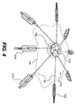
上述のように、様々な実施例では、本開示の創傷治療器具を使用して、様々なタイプ、形状、大きさ、及び場所を有する創傷を治療し得る。例えば、図4は、より不規則な形状の創傷155を治療するよう使用される、図1の創傷治療器具100の特定の実施例を示す。図4に示さない図1の様々な構成要素を図4の実施例に使用できる。
As described above, in various embodiments, wounds of various types, shapes, sizes, and locations may be treated using the wound treatment device of the present disclosure. For example, FIG. 4 shows a particular embodiment of the
図4に示すように、機械的治療器具110は、様々な方向に延びる8つの細長部140を有する。さらに、創傷155の周縁に対するコネクタ142の位置を調整して、創傷155の凹凸に適合させた。このため、様々な実施例では、機械的治療器具が、張力を発生させて組織の伸長及び/又は創傷の閉合を助ける細長部の数、長さ、及び位置を制御できることによって、様々な形状及び大きさの創傷を治療する際に柔軟性を与える。
As shown in FIG. 4, the
細長部140を移動させることによるコネクタ142の位置の調整に加えて、細長部140及び/又はコネクタ142の長さ及び位置を多くの他の方法で制御して、創傷の周りにコネクタ142を適切に配置させ得る。例えば、ある実施例では、コネクタ142の長さを調整し得る。他の実施例では、コネクタ142が細長部140に付く位置を調整して、第1の本体130からコネクタ142までの距離を制御し得る。
In addition to adjusting the position of the
ある実施例では、コネクタ142が調整可能な長さを有することで、第1の本体130から患者の組織又はシートへのコネクタ142の取り付け位置までの距離を制御し得る。図5A−5Bは、調整可能なコネクタ142の特定の実施例を示す。図5Aは、より伸長した構成の調整可能なコネクタを示しており、図5Bは、短い構成の図5Aの調整可能なコネクタを示す。
In some embodiments, the
図示するように、コネクタ142は、その長さに沿った一連のノッチ又は頂部508を有するタブ部504を有する。さらに、タブ部504の近位端505が、細長部140に取り付けられる。さらに、コネクタ142は、上述のように、患者の組織又は柔軟性のあるシート160に接着するよう付けることができる下面516を有するタブ受容部500を有する。図示するように、タブ受容部500は、タブ部504を受容するよう構成された開口部及び通路510を有する。さらに、タブ部504が通路510の中に前進すると、頂部又はノッチ508が、固定機構512の内側に突出する部分514に係合することで、タブ受容部500の中でタブ部504を固定する。ある実施例では、固定機構512が、ある方向へのタブ受容部500の中でのタブ部504の摺動移動を防止する一方、反対方向への摺動移動を可能にする。ある実施例では、固定機構512により、タブ部504が、タブ受容部500の中に摺動できることで、タブ部504に取り付けられたタブ受容部500から細長部140の端部までの距離を短くし、タブ部504がタブ受容部500の外に移動しないようにすることで、タブ受容部500及びタブ部504に取り付けられた細長部140の端部からの距離の増加を抑える。
As shown, the
図示するように、タブ受容部500の中で所望の距離だけタブ部504を前進させ得ることで、タブ受容部500とタブ部504に取り付けられた細長部140の端部との間の距離を調整し、コネクタ142全体の長さを制御する。例えば、図5Bに示すように、タブ部504をほぼ完全に前進させて、タブ受容部500とタブ部504に取り付けられた細長部140の端部との間の距離を短くし得る。代替的に、タブ受容部500の中に短い距離だけタブ部504を前進させることによって、タブ受容部500とタブ部504に取り付けられた細長部140の端部との間の距離を長くすることができる。
As shown, the
コネクタ142を患者の組織又はシート160に付ける前に又はコネクタ142を患者の組織又はシート160に付けた後に、コネクタ142の長さを調整できる。ある実施例では、タブ受容部500を組織又はシート160に取り付け、その後で、タブ部504をタブ受容部500の中に挿入又はその中で調整して、タブ部504に取り付けられた細長部140の張力を増やす。ある実施例では、タブ部504をタブ受容部500の中の選択位置に調整し、その後でタブ受容部500を組織又はシート160に付ける。
The length of the
様々な実施例では、細長部140に沿ったコネクタの位置を調整することによって、第1の本体130からのコネクタの距離を制御できる。図6A−6Bは、特定の典型的な実施例に係る調整可能なコネクタ600及び創傷治療器具の細長部140を示す。これらの実施例では、コネクタ600が、細長部140の長さに沿って調整可能に位置決めされる。図示するように、コネクタ600は、コネクタ本体604及び固定本体608を有する。ある実施例では、固定本体608が、細長部140を受容するための開口部612を有する一方、コネクタ本体604が、細長部140を受容するための溝部620を有する。ある実施例では、カバー630が、本体604の上部に取り付けられており、溝部620を覆う。
In various embodiments, by adjusting the position of the connector along the
図6Aに示すように、細長部140の長さに沿ってコネクタ600を調整できる。そして、コネクタ600を所定の位置でロックするために、固定本体608が、細長部140が溝部620及び開口部612を通る状態で、コネクタ本体610の長穴610の中に押し込まれることで、細長部140に力を加えて細長部140を押し付け、細長部140に沿った所定の位置にコネクタ600を固定する。
As shown in FIG. 6A, the
様々な実施例では、固定本体608及び長穴610を、長穴610の中に固定本体608を挿入すると細長部140とともに圧入結合を形成するような大きさにできる。ある実施例では、このような結合によって形成される圧力が、細長部140の所定の位置にコネクタ600を保持するのに十分である。ある実施例では、接着剤又は他の結合機構を使用して、長穴610の中で固定本体608を固定し得る。
In various embodiments, the fixed
コネクタ142と同じ方法で、接着剤を用いて患者の組織又はシート160にコネクタ600を取り付け得る。特定の実施例では、コネクタ600を細長部140に配置して所定の位置に固定した後に、上述のように、接着剤を、コネクタ600が取り付けられるコネクタ600の下面616又は組織又はシート面(例えば、両面テープ)に適用又は露出し得る。さらに、上述のように、特定の実施例では、各コネクタ600を患者の組織又はシート160に付けた後に、機械的治療器具を締め付けて、創傷の周囲の組織に所望の大きさの張力を発生させることができる。
In the same manner as
様々な実施例では、第1の本体130が、細長部140を締め付けて周囲の組織に所望の大きさの張力を発生させ易くするための多くの機構を有する。ある実施例では、第1の本体130が、細長部140を短くすることで、張力を増やし及び/又は周囲の組織を伸ばすための回転部を有する。
In various embodiments, the
図7Aは、特定の実施例に係る第1の本体130の拡大図を示しており、図7Bは、図7Aの第1の本体130の部分的に切り取った図を示す。図示するように、細長部140は、様々な方向に第1の本体130から延びている。さらに、上述のように、様々な実施例では、治療される特定の創傷に基づいて、各細長部140の数及び位置を変更又は調整し得る。
7A shows an enlarged view of the
図7A及び7Bに示すように、第1の本体130は回転部700を有する。様々な実施例では、回転部700は、(図7Bに示すように)細長部140が取り付けられる内壁720に動作可能に係合する。ある実施例では、内壁720が略円筒形を有しており、細長部140が内壁720の面に取り付けられる。このため、回転部700が回転すると、内壁720が回転する。内壁720が回転すると、内壁720に取り付けられた細長部140が、内壁720に少なくとも部分的に包まれる。ある実施例では、内壁720の周囲に細長部140が包まれることで、細長部140が第1の本体130から延びる距離が減少して、上述のように、コネクタ142又はシート160に取り付けた組織に所望の張力を発生させる。ある実施例では、ある方向への回転部700の回転が、細長部140が第1の本体130から延びている距離を減少させる。特定の実施例では、第1の方向とは反対の第2の方向への回転部700の回転により、細長部140が第1の本体130から延びる距離を増加させる。
As shown in FIGS. 7A and 7B, the first
様々な実施例では、回転部700を固定することで、所望の程度に締め付けた後に細長部140が第1の本体130から延びる長さを固定するのが望ましい。このため、ある実施例では、第1の本体130が、さらに、内壁720及び/又は回転部700に動作可能に係合する固定機構730を有する。ある実施例では、ある方向に回転又は締め付けできるが、他の方向には回転又は締め付けできないよう固定機構730を構成することで、回転部700を捻ることによって締め付け、反対方向の回転を防止することによって緩みを防止する。ある実施例では、固定機構730が、当技術分野で周知のように、ラチェット機構又はラチェット及び歯止めを有する。さらに、特定の実施例では、ラチェット機構が、必要に応じて締め付けたり緩めたりし得るようリバーシブルである。様々な実施例では、第1の本体130が解放機構735を有する。ある実施例では、解放機構735が、係脱又は固定機構730の方向を反転させるよう固定機構730の動作を制御し得るボタン又はスイッチを有する。ある実施例では、解放機構735が、固定機構730の動作方向を反転させることができ、第1の方向に回転できるが第2の方向に回転できず、又は第2の方向に回転できるが第1の方向に回転できない。ある実施例では、解放機構735が、固定機構730を解放していずれの方向にも回転し得る。
In various embodiments, it may be desirable to fix the length of the
図示するように、図7A及び7Bの特定の実施例では、第1の本体130が、さらに、内壁720に取り付ける前に細長部140が通過し得る開口部710を有する外壁708を有する。ある実施例では、これらの開口部は、第1の本体130の周縁に固定位置を有する。ある実施例では、開口部700が移動するときに、開口部が移動しないことで、細長部140が締め付けられたときでも、細長部140が周囲の組織に力をかける方向を制御する。
As shown, in the particular embodiment of FIGS. 7A and 7B, the
さらに、上述のように、ある実施例では、創傷治療器具100が、減圧治療とともに機械的な治療を可能にする。したがって、図7Bに示すように、第1の本体130が、さらに、減圧治療システムのポンプ122の流路124に係合するよう構成されたコネクタ126を有する。図示するように、コネクタ126は流路124に流体結合する開口部128を有する。開口部128は第1の本体130を通過し、創傷及び包帯剤に液通する流路129に液通しており、減圧治療を与える。
Further, as described above, in certain embodiments, the
図8Aは、特定の典型的な実施例に係る創傷治療器具200を示す。図示するように、器具200は機械的治療器具210を有しており、さらに第1の本体130と同じような第1の本体230を有する。さらに、器具210は、下方の治療される創傷を密閉するシート160に取り付けられ様々な方向に延びる多くの細長部140を有する。図示すように、細長部140は、図6A及び6Bを参照して説明したコネクタ600を用いてシートに取り付けられる。様々な実施例では、ここで説明した任意のコネクタを使用し得る。
FIG. 8A shows a
図8Bは、図8Aの器具を部分的に切り取った図を示しており、器具の内部の構成要素を示す。図示するように、第1の本体230は、スプール又は締め付け機構240に取り付けられる回転部250を有する。各細長部140は、このスプール又は締め付け機構に取り付けられ、回転部250が回転すると、締め付け機構が細長部140の張力を増加させるよう係合することで、コネクタ600に機械的に結合した創傷の周縁を接近するよう引っ張る。
FIG. 8B shows a partially cut away view of the device of FIG. 8A, showing the internal components of the device. As shown in the figure, the first
さらに、第1の本体130を参照して上述したように、特定の実施例では、器具200が、ある方向に回転できるが逆方向の回転を防止するラチェットシステムといった内部の固定機構を有する。ある実施例では、スプール又は締め付け機構240が、一連のギヤを有しており、機械的な利点を与え、回転部250を回転させる過度な労力無しに、細長部140に発生する張力が増加できる。
Furthermore, as described above with reference to the
特定の実施例では、上述のように、創傷の機械的な閉合をし易くするよう第1の本体230を構成し得る一方、減圧治療を可能とする。したがって、特定の実施例では、第1の本体230が、流路124を介してポンプ122に流体結合し得る流体コネクタ226を有する。流体コネクタ226は開口部228を有しており、第1の本体230を横断する流路229と連通し、創傷との液通を防止する。
In certain embodiments, as described above, the
図9は、創傷治療器具900の特定の典型的な実施例を示す。上述した特定の器具のように、器具900が、第1の本体930から延びて患者の組織又は面916を用いて柔軟性のあるシート160(図示せず)に接着するよう構成されたコネクタ942を有する2又はそれ以上の細長部940を有する第1の本体930を有する。さらに、器具900は、上述のように、減圧治療器具120に係合するよう構成されたコネクタ926を有する。
FIG. 9 shows a specific exemplary embodiment of a
しかしながら、これらの実施例では、各細長部940が、細長部受容部946で第1の本体930に調整可能に結合されている。ここで、細長部940の近位端部950が、ある実施例では細長部940の雄コネクタ部を形成する対応する近位端部950を受容するよう構成された雌コネクタ開口部を有する細長部受容部946を通過する。さらに、端部950を取り付け領域946を通してさらに引っ張って、第1の本体930から延びる各細長部940の長さを短くすることができ、各細長部940に所望の張力を発生させる。ある実施例では、細長部940の長さを調整した後に、端部950を除去又は切り離して器具の大きさを小さくし所望に応じて上方のシートの配置が可能となる。ある実施例では、細長部940が、小さな頂部又はノッチ908を有しており、細長部受容部946を通して細長部940を引くことができ、締め付けた後に細長部940が開口部の外に引き戻されるのを防止する固定機構を与える。様々な実施例では、発生する所望の張力の程度に基づいて、特定の固定機構を選択できるが、1つの適切な機構は、プラスチックのハンドカフ又はタイといった従来説明される器具に使用されるのと同じである。
However, in these embodiments, each
上述のように、様々な実施例では、まっすぐな又は不規則な形状を有する創傷について創傷治療器具を使用できる。図10は、特定の実施例に係るほぼまっすぐな創傷で使用する機械的創傷治療器具810を示しており、図11は、減圧治療器具とともに図10の創傷治療器具を示す。図示すように、器具810は第1の本体830を有する。2対の細長部840,840’が、第1の本体830から延びている。特定の実施例では、各細長部840,840’が、1対の略平行な細長いアームを有する。さらに、コネクタ842,842’が、細長部840,840’の各対の第1の端部領域841,841’間を延びており、患者の皮膚又は他の組織、又は創傷の上方のシート160に取り付け得る平らな又は拡大された領域を形成する。細長部840,840’の各アームが、第1の本体830の開口部812を通過でき、コネクタ842,842’から第1の本体830の反対側の細長いアームの第2の端部882,882’に延びている。特定の実施例では、操作領域880,880’が、細長いアームの各対の第2の領域882,882’間を延びている。
As described above, in various embodiments, a wound treatment device can be used for wounds having a straight or irregular shape. FIG. 10 shows a mechanical
上述のように、コネクタ842,842’を、組織又は創傷部位の周囲のシートに取り付け得る。ある実施例では、コネクタ842,842’を、上述のように接着剤を用いて付けることができることで、皮膚又は他の組織を貫通させずに、創傷の周囲の組織に力をかけることができる。
As described above, the
ある実施例では、創傷を囲む組織、又は創傷の上方のシート160にコネクタ842,842’を取り付けた後に、コネクタ842,842’を一緒に引っ張って、創傷の閉合又は創傷の端部の接近を助ける力をかけることができる。図10に示す方向860,860’に操作領域880,880’を引っ張ることによって、この力を発生させることができ、これにより、図10に示す方向864,864’にコネクタ842,842’を一緒に引く。
In one embodiment, after attaching the
特定の実施例では、所定の位置にコネクタ842,842’を保持することで、創傷の周縁に持続的な力をかけることができ、第1の本体830及び細長部840,840’が固定機構を有する。例えば、特定の実施例では、細長部840,840’が、その少なくとも1の面に沿った頂部又は切欠部808を有しており、第1の本体830が、一方又は双方への細長部842,842’の移動を防止する内部機構を有する。
In certain embodiments, holding the
ある実施例では、第1の本体830が、細長部を受容するためのさらなる開口部828を有する。ある実施例では、細長部840,840’を第1の本体830の長さに沿った様々な位置に配置できるよう、さらなる開口部828を配置させ得る。ある実施例では、開口部812及びさらなる開口部828を、他の構成を有する細長部を受容するよう構成し得る。例えば、特定の実施例では、(図9に示すような)細長部940を図10の第1の本体830とともに使用できる。ある実施例では、2又はそれ以上の細長部940が、細長部940が第1の本体830から反対方向に延びるように、第1の本体830に取り付けられる。ある実施例では、多数の細長部940が第1の本体830から延びており、まっすぐな創傷の長さに沿って機械的な力を与える。
In some embodiments, the
上述のように、本開示の機械的治療器具を、機械的な治療を容易にして創傷の閉合を補助する一方、減圧治療を可能にするよう構成し得る。したがって、器具810は、図11に示すように、減圧治療器具の流路124に結合するよう構成された流体コネクタ826を有する。上述のように、特定の実施例では、第1の本体830を横断する流路に流体コネクタ826を流体結合でき、器具810の下方の創傷部位との液通を与える。ある実施例では、流体コネクタ826を第1の本体830の下面に向けて下方に延びる流路に結合できる。ある実施例では、側面に沿って又は第1の本体830に沿った他の場所に流路を配置し得る。例えば、ある実施例では、1又はそれ以上の開口部828が、流体コネクタ826と液通する流路を形成できる。
As described above, the mechanical treatment device of the present disclosure may be configured to facilitate reduced pressure treatment while facilitating mechanical treatment to assist in wound closure. Accordingly, the
特定の実施例では、器具800を創傷に取り付け減圧治療ポンプ122を係合した後に、シート160を器具800の上方に配置して創傷を密閉でき、機械的な治療及び減圧治療の双方が可能となる。ある実施例では、シートが、開口部162を有しており、流体コネクタ826がシートを通過できる。さらに、上述の特定の器具と同様に、特定の実施例では、機械的治療器具800の下方にシート160を配置でき、シート160に器具を接着してシート160の下方に位置する組織に機械的な力を伝えることができる。
In certain embodiments, after the device 800 is attached to the wound and the reduced
特定の実施例では、様々な解剖学的部位との柔軟性のある結合を可能にするために、細長部840,840’及びコネクタ842,842’を、図示するように、柔軟性の有る材料で形成できる。しかしながら、特定の実施例では、特定の解剖学的部位及び治療される創傷に基づいて、より硬い構成を選択できる。
In certain embodiments, the
様々な実施例では、本開示の器具を使用して、多くの様々な解剖学的部位の創傷を治療できる。さらに、本器具をある大きさで示したが、様々な実施例では、特定の患者及び治療される解剖学的部位に基づいて、器具の大きさを決めることができる。さらに、減圧治療とともに使用するための器具を説明したが、様々な実施例では、特に皮膚又は他の組織を貫通させずに創傷を閉合するために機械的な補助を与えるのが望ましい場合に、本開示の機械的治療器具を単独で、又は減圧治療システム無しで使用できる。 In various embodiments, the devices of the present disclosure can be used to treat many different anatomical wounds. Further, although the instrument is shown in a certain size, in various embodiments, the instrument can be sized based on the particular patient and the anatomical site being treated. In addition, although an instrument for use with reduced pressure treatment has been described, in various embodiments it may be desirable to provide mechanical assistance, particularly to close the wound without penetrating the skin or other tissue. The mechanical treatment device of the present disclosure can be used alone or without a reduced pressure treatment system.
他の実施例が、本明細書及びここで開示された器具及び方法の実施例を考慮することで、当業者にとって明らかであろう。
Other embodiments will be apparent to those skilled in the art from consideration of the specification and embodiments of the devices and methods disclosed herein.
Claims (20)
減圧源(120)に取り付けるよう構成された少なくとも1の第1の開口部(128)及び第1の本体を通して少なくとも部分的に延びて前記少なくとも1の開口部に液通する少なくとも1の流路(129)を具える第1の本体(130)と、
それぞれが前記第1の本体に取り付けられ、異なる方向に前記第1の本体から延びて、前記第1の本体に対して調製可能な長さを有する4又はそれ以上の細長部(140)と、
4又はそれ以上のコネクタ(142)とを具えており、
前記コネクタのそれぞれが、前記細長部の1つに取り付けられており、
前記コネクタが、それぞれ、タブ部(504)及び前記タブ部に摺動可能に係合するよう構成されたタブ受容部(500)を具えており、
前記タブ受容部と前記タブ部に取り付けられた前記細長部の一方の端との間の長さが、調節可能であることを特徴とする器具。 A wound care device (100) comprising:
At least one first opening (128) configured to attach to a reduced pressure source (120) and at least one flow path (at least partially extending through the first body and fluidly passing through the at least one opening); 129) a first body (130),
Four or more elongate portions (140) each attached to the first body and extending from the first body in different directions and having a length adjustable with respect to the first body;
4 or more connectors (142),
Each of the connectors is attached to one of the elongated portions;
The connectors each comprise a tab portion (504) and a tab receiving portion (500) configured to slidably engage the tab portion;
A device wherein the length between the tab receiving portion and one end of the elongated portion attached to the tab portion is adjustable.
前記第1の本体の前記第1の開口部に係合するよう構成された端部を有する管状部材(124)と、A tubular member (124) having an end configured to engage the first opening of the first body;
前記管状部材の中に減圧を発生させるよう構成されたポンプシステム(122)と、A pump system (122) configured to generate a reduced pressure in the tubular member;
を具えることを特徴とする請求項18に記載の器具。The instrument of claim 18, comprising:
実質的に硬質の材料の本体を有する第1の本体(130)と;A first body (130) having a body of substantially rigid material;
4又はそれ以上の細長部(140)であって、それぞれが、前記第1の本体に取り付けられ、異なる方向に前記第1の本体から延びており、前記第1の本体に対して調整可能な長さを有する細長部と;4 or more elongate portions (140), each attached to the first body and extending from the first body in different directions and adjustable relative to the first body An elongated portion having a length;
前記4又はそれ以上の細長部の一方にそれぞれ取り付けられる4又はそれ以上のコネクタ(142)を創傷(150)を囲む組織に機械的に結合させるための接着剤と;An adhesive for mechanically coupling four or more connectors (142), each attached to one of the four or more elongated portions, to the tissue surrounding the wound (150);
を具えており、With
前記コネクタが、それぞれ、タブ部(504)及び前記タブ部に摺動可能に係合するよう構成されたタブ受容部(500)を具えており、The connectors each comprise a tab portion (504) and a tab receiving portion (500) configured to slidably engage the tab portion;
前記タブ受容部と前記タブ部に取り付けられた前記細長部の一方の端との間の長さが、調節可能であることを特徴とする器具。A device wherein the length between the tab receiving portion and one end of the elongated portion attached to the tab portion is adjustable.
Applications Claiming Priority (3)
| Application Number | Priority Date | Filing Date | Title |
|---|---|---|---|
| US12/326,589 US8721629B2 (en) | 2008-12-02 | 2008-12-02 | System and method for mechanical closure of wounds |
| US12/326,589 | 2008-12-02 | ||
| PCT/US2009/066049 WO2010065435A2 (en) | 2008-12-02 | 2009-11-30 | System and method for mechanical closure of wounds |
Publications (3)
| Publication Number | Publication Date |
|---|---|
| JP2012510318A JP2012510318A (en) | 2012-05-10 |
| JP2012510318A5 JP2012510318A5 (en) | 2012-11-15 |
| JP5806937B2 true JP5806937B2 (en) | 2015-11-10 |
Family
ID=42223477
Family Applications (1)
| Application Number | Title | Priority Date | Filing Date |
|---|---|---|---|
| JP2011538707A Expired - Fee Related JP5806937B2 (en) | 2008-12-02 | 2009-11-30 | System and method for mechanical closure of a wound |
Country Status (11)
| Country | Link |
|---|---|
| US (2) | US8721629B2 (en) |
| EP (1) | EP2352441B1 (en) |
| JP (1) | JP5806937B2 (en) |
| KR (1) | KR20110101171A (en) |
| CN (1) | CN102231966B (en) |
| AU (1) | AU2009322616B2 (en) |
| BR (1) | BRPI0916472A2 (en) |
| CA (1) | CA2744186A1 (en) |
| MX (1) | MX2011005709A (en) |
| RU (1) | RU2011122551A (en) |
| WO (1) | WO2010065435A2 (en) |
Cited By (1)
| Publication number | Priority date | Publication date | Assignee | Title |
|---|---|---|---|---|
| JP2015522352A (en) * | 2012-07-06 | 2015-08-06 | ザ ジェネラル ホスピタル コーポレイション | Method and apparatus for skin treatment |
Families Citing this family (61)
| Publication number | Priority date | Publication date | Assignee | Title |
|---|---|---|---|---|
| AU2008310622B2 (en) | 2007-10-11 | 2014-01-09 | Solventum Intellectual Properties Company | Closed incision negative pressure wound therapy device and methods of use |
| GB0804654D0 (en) | 2008-03-13 | 2008-04-16 | Smith & Nephew | Vacuum closure device |
| EP2416816B1 (en) * | 2009-04-10 | 2014-10-15 | Spiracur Inc. | Methods and devices for applying closed incision negative pressure wound therapy |
| US8444614B2 (en) | 2009-04-10 | 2013-05-21 | Spiracur, Inc. | Methods and devices for applying closed incision negative pressure wound therapy |
| DE102009036165A1 (en) * | 2009-07-28 | 2011-02-03 | Karl Storz Gmbh & Co. Kg | Device for stretching tissue areas |
| US9649408B1 (en) | 2009-11-05 | 2017-05-16 | Lifecell Corporation | Systems and methods for sterilization of bone or bone components |
| EP2515961B1 (en) | 2009-12-22 | 2019-04-17 | Smith & Nephew, Inc. | Apparatuses for negative pressure wound therapy |
| US8424532B2 (en) | 2010-07-26 | 2013-04-23 | Medline Industries, Inc. | Cranial surgical drape |
| US9050398B2 (en) * | 2010-12-22 | 2015-06-09 | Smith & Nephew, Inc. | Apparatuses and methods for negative pressure wound therapy |
| US9421132B2 (en) | 2011-02-04 | 2016-08-23 | University Of Massachusetts | Negative pressure wound closure device |
| CN106974683B (en) | 2011-02-04 | 2020-02-21 | 马萨诸塞州大学 | Negative pressure wound closure device |
| US9278166B2 (en) | 2011-03-02 | 2016-03-08 | Medline Industries, Inc. | Method and apparatus pertaining to a medical drape having a suction port |
| EP2567681B1 (en) * | 2011-09-09 | 2014-11-12 | Paul Hartmann AG | Wound dressing for the abdominal area |
| USD733896S1 (en) * | 2012-05-04 | 2015-07-07 | Genadyne Biotechnologies, Inc. | Abdominal dressing |
| WO2013175310A2 (en) | 2012-05-22 | 2013-11-28 | Smith & Nephew Plc | Apparatuses and methods for wound therapy |
| CA2874396A1 (en) | 2012-05-22 | 2014-01-23 | Smith & Nephew Plc | Wound closure device |
| CA2874581C (en) | 2012-05-24 | 2022-06-07 | Smith & Nephew Inc. | Devices and methods for treating and closing wounds with negative pressure |
| US10888375B2 (en) | 2012-07-06 | 2021-01-12 | The General Hospital Corporation | Method and apparatus for dermatological treatment |
| AU2013290346B2 (en) | 2012-07-16 | 2018-06-07 | Smith & Nephew, Inc. | Negative pressure wound closure device |
| US9655623B2 (en) * | 2013-02-15 | 2017-05-23 | Alan E. Nash | System for closing a wound |
| EP2968016B1 (en) | 2013-03-13 | 2018-07-11 | Smith&Nephew, Inc. | Negative pressure wound closure device and systems and methods of use in treating wounds with negative pressure |
| US10159771B2 (en) | 2013-03-14 | 2018-12-25 | Smith & Nephew Plc | Compressible wound fillers and systems and methods of use in treating wounds with negative pressure |
| AU2014291873B2 (en) | 2013-07-16 | 2019-01-24 | Smith & Nephew Plc | Apparatus for wound therapy |
| US20150112227A1 (en) * | 2013-10-18 | 2015-04-23 | Leonard DiGiovanna | Phlebotomy aid device |
| JP6723917B2 (en) | 2013-10-21 | 2020-07-15 | スミス アンド ネフュー インコーポレイテッド | Negative pressure wound closure device |
| US10179073B2 (en) | 2014-01-21 | 2019-01-15 | Smith & Nephew Plc | Wound treatment apparatuses |
| JP6742908B2 (en) | 2014-01-21 | 2020-08-19 | スミス アンド ネフュー ピーエルシーSmith & Nephew Public Limited Company | Crushable negative pressure wound dressing |
| US9770369B2 (en) | 2014-08-08 | 2017-09-26 | Neogenix, Llc | Wound care devices, apparatus, and treatment methods |
| US10524793B2 (en) * | 2015-02-13 | 2020-01-07 | St. Michael's Hospital | Device for management of an open abdomen |
| EP3288509B1 (en) | 2015-04-29 | 2022-06-29 | Smith & Nephew, Inc | Negative pressure wound closure device |
| WO2017019939A1 (en) | 2015-07-29 | 2017-02-02 | Innovative Therapies, Inc. | Wound therapy device pressure monitoring and control system |
| EP3123947A1 (en) * | 2015-07-31 | 2017-02-01 | Kantonsspital Basselland | Stretching device for stretching an abdominal wall |
| CN105147344B (en) * | 2015-10-19 | 2018-12-21 | 张新平 | Skin wound assists device for healing |
| US11471586B2 (en) | 2015-12-15 | 2022-10-18 | University Of Massachusetts | Negative pressure wound closure devices and methods |
| US10575991B2 (en) | 2015-12-15 | 2020-03-03 | University Of Massachusetts | Negative pressure wound closure devices and methods |
| US10814049B2 (en) | 2015-12-15 | 2020-10-27 | University Of Massachusetts | Negative pressure wound closure devices and methods |
| USD798461S1 (en) * | 2016-01-15 | 2017-09-26 | Genadyne Biotechnologies, Inc. | Abdominal dressing |
| US11020199B2 (en) | 2016-03-14 | 2021-06-01 | Medline Industries, Inc. | Surgical drape |
| US11135351B2 (en) | 2016-08-30 | 2021-10-05 | Smith & Nephew Plc | Systems and methods for applying reduced pressure therapy |
| EP3518847B1 (en) | 2016-09-27 | 2023-03-01 | Smith & Nephew plc | Wound closure devices with dissolvable portions |
| WO2018085457A1 (en) | 2016-11-02 | 2018-05-11 | Smith & Nephew Inc. | Wound closure devices |
| US11596405B2 (en) * | 2017-01-27 | 2023-03-07 | Black Diamond Creations, Llc | Sutureless device and method for closing a tissue opening |
| KR101993288B1 (en) * | 2017-05-11 | 2019-09-30 | 한문석 | Drain Tube Fixation and Surgical Skin Closure |
| WO2018230402A2 (en) * | 2017-06-12 | 2018-12-20 | Terumo Kabushiki Kaisha | Subcutaneous tissue device |
| US11324876B2 (en) | 2017-06-13 | 2022-05-10 | Smith & Nephew Plc | Collapsible structure and method of use |
| AU2018285236B2 (en) | 2017-06-13 | 2024-02-29 | Smith & Nephew Plc | Wound closure device and method of use |
| JP7419072B2 (en) | 2017-06-14 | 2024-01-22 | スミス アンド ネフュー ピーエルシー | Foldable sheet for wound closure and method of use |
| EP3638173A1 (en) | 2017-06-14 | 2020-04-22 | Smith & Nephew, Inc | Control of wound closure and fluid removal management in wound therapy |
| JP2020523052A (en) | 2017-06-14 | 2020-08-06 | スミス アンド ネフュー インコーポレイテッド | Fluid removal management and control of wound closure in wound care |
| US11583623B2 (en) | 2017-06-14 | 2023-02-21 | Smith & Nephew Plc | Collapsible structure for wound closure and method of use |
| EP3658090B1 (en) | 2017-07-27 | 2021-11-10 | Smith & Nephew PLC | Customizable wound closure device |
| EP3664756B1 (en) | 2017-08-07 | 2024-01-24 | Smith & Nephew plc | Wound closure device with protective layer |
| WO2019042790A1 (en) | 2017-08-29 | 2019-03-07 | Smith & Nephew Plc | Systems and methods for monitoring wound closure |
| USD884905S1 (en) | 2018-01-18 | 2020-05-19 | Medline Industries, Inc. | Surgical C-section drape with tunnel |
| US11246675B2 (en) | 2018-01-18 | 2022-02-15 | Medline Industries, Lp | Surgical C-section drape with tunnel |
| GB201811449D0 (en) | 2018-07-12 | 2018-08-29 | Smith & Nephew | Apparatuses and methods for negative pressure wound therapy |
| KR102165073B1 (en) * | 2018-08-30 | 2020-10-13 | 주식회사 제이앤킴 | Suture retention device |
| WO2020186730A1 (en) * | 2019-03-19 | 2020-09-24 | 景润(上海)医疗器械有限公司 | Surgical assistance device for sutureless wound closure of skin wounds in deep fascia of limbs |
| CN111714171B (en) * | 2019-03-19 | 2023-11-24 | 景润(上海)医疗器械有限公司 | Surgical auxiliary device for closing skin wound without suture in skin superficial fascia |
| CN212756131U (en) * | 2019-06-20 | 2021-03-23 | 杨国煌 | Fluid-carrying applicator |
| CN113729824B (en) * | 2021-08-24 | 2023-01-03 | 温州医科大学附属第一医院 | Healing device is assisted to sinus |
Family Cites Families (48)
| Publication number | Priority date | Publication date | Assignee | Title |
|---|---|---|---|---|
| US352356A (en) | 1886-11-09 | Ors to william wharton | ||
| US360463A (en) | 1887-04-05 | Joseph e | ||
| US2971510A (en) * | 1960-03-18 | 1961-02-14 | Atlantic Surgical Company Inc | Surgical drainage device |
| US3874387A (en) | 1972-07-05 | 1975-04-01 | Pasquale P Barbieri | Valved hemostatic pressure cap |
| GB1562244A (en) | 1976-11-11 | 1980-03-05 | Lock P M | Wound dressing materials |
| US4569348A (en) | 1980-02-22 | 1986-02-11 | Velcro Usa Inc. | Catheter tube holder strap |
| US4373519A (en) | 1981-06-26 | 1983-02-15 | Minnesota Mining And Manufacturing Company | Composite wound dressing |
| JPH0332364Y2 (en) * | 1986-11-25 | 1991-07-09 | ||
| JP2719671B2 (en) | 1989-07-11 | 1998-02-25 | 日本ゼオン株式会社 | Wound dressing |
| US5263971A (en) | 1991-02-13 | 1993-11-23 | Life Medical Sciences, Inc. | Apparatus for the closure of wide skin defects by stretching of skin |
| US5149331A (en) | 1991-05-03 | 1992-09-22 | Ariel Ferdman | Method and device for wound closure |
| US7198046B1 (en) | 1991-11-14 | 2007-04-03 | Wake Forest University Health Sciences | Wound treatment employing reduced pressure |
| US5636643A (en) | 1991-11-14 | 1997-06-10 | Wake Forest University | Wound treatment employing reduced pressure |
| US5645081A (en) | 1991-11-14 | 1997-07-08 | Wake Forest University | Method of treating tissue damage and apparatus for same |
| USD352356S (en) | 1992-12-03 | 1994-11-08 | Life Medical Sciences, Inc. | Surgical contractor for the closure of wide skin defects |
| FR2690840B1 (en) | 1992-05-07 | 1994-08-19 | Patrick Frechet | Living tissue extension device. |
| USD360463S (en) | 1993-08-13 | 1995-07-18 | Steiner Mark T | Surgical contractor for the closure of skin defects |
| US5437651A (en) | 1993-09-01 | 1995-08-01 | Research Medical, Inc. | Medical suction apparatus |
| US5441540A (en) | 1993-09-20 | 1995-08-15 | Kim; Paul S. | Method and apparatus for skin tissue expansion |
| DE4342457C2 (en) | 1993-12-13 | 1997-04-17 | Wim Dr Med Fleischmann | Device for stimulating tissue regeneration in large and deep tissue defects |
| US5507775A (en) | 1994-01-21 | 1996-04-16 | Progressive Surgical Products Inc. | Tissue expansion and approximation device |
| US5662714A (en) | 1994-01-21 | 1997-09-02 | M.X.M. | Device for extending living tissues |
| US5549584A (en) | 1994-02-14 | 1996-08-27 | The Kendall Company | Apparatus for removing fluid from a wound |
| JPH08196538A (en) * | 1994-09-26 | 1996-08-06 | Ethicon Inc | Tissue sticking apparatus for surgery with elastomer component and method of attaching mesh for surgery to said tissue |
| CN1149958C (en) | 1994-12-12 | 2004-05-19 | 维姆·弗莱施曼 | Skin traction device |
| US5649960A (en) * | 1995-02-03 | 1997-07-22 | Pavletic; Michael M. | Apparatus and method for accelerating the stretching of skin |
| DE19513961C2 (en) | 1995-04-13 | 1997-03-06 | Wim Dr Med Fleischmann | Device for stimulating tissue regeneration in the case of tissue defects |
| FI107124B (en) | 1996-03-01 | 2001-06-15 | Rolf E A Nordstroem | Surgical suture |
| FR2757371B1 (en) | 1996-12-20 | 1999-03-26 | Mxm | ELASTIC DEVICE WITH LARGE ELONGATION CAPACITY FOR LIVE TISSUE EXTENSION |
| NL1006457C2 (en) * | 1997-07-03 | 1999-01-05 | Polymedics N V | Drainage system to be used with an open wound, element used for applying a drainage pipe or hose and method for applying the drainage system. |
| US6135116A (en) | 1997-07-28 | 2000-10-24 | Kci Licensing, Inc. | Therapeutic method for treating ulcers |
| GB9719520D0 (en) | 1997-09-12 | 1997-11-19 | Kci Medical Ltd | Surgical drape and suction heads for wound treatment |
| JP3112874B2 (en) * | 1997-11-10 | 2000-11-27 | 富士システムズ株式会社 | Medical tubing |
| US6071267A (en) | 1998-02-06 | 2000-06-06 | Kinetic Concepts, Inc. | Medical patient fluid management interface system and method |
| US6856821B2 (en) | 2000-05-26 | 2005-02-15 | Kci Licensing, Inc. | System for combined transcutaneous blood gas monitoring and vacuum assisted wound closure |
| US6494896B1 (en) | 1999-11-30 | 2002-12-17 | Closure Medical Corporation | Applicator for laparoscopic or endoscopic surgery |
| US7361185B2 (en) * | 2001-05-09 | 2008-04-22 | Canica Design, Inc. | Clinical and surgical system and method for moving and stretching plastic tissue |
| US6471685B1 (en) * | 2000-05-18 | 2002-10-29 | David James Johnson | Medical dressing assembly and associated method of using the same |
| DE10209122B4 (en) | 2002-03-01 | 2006-04-13 | Fleischmann, Wilhelm, Dr.med. | Instrument for tissue dilation of the skin |
| US20040122434A1 (en) | 2002-08-23 | 2004-06-24 | Argenta Louis C. | Bone treatment employing reduced pressure |
| US7846141B2 (en) | 2002-09-03 | 2010-12-07 | Bluesky Medical Group Incorporated | Reduced pressure treatment system |
| US20040267309A1 (en) | 2003-06-27 | 2004-12-30 | Garvin Dennis D. | Device for sutureless wound closure |
| US7455681B2 (en) | 2004-09-13 | 2008-11-25 | Wound Care Technologies, Llc | Wound closure product |
| US7485112B2 (en) * | 2004-11-08 | 2009-02-03 | Boehringer Technologies, L.P. | Tube attachment device for wound treatment |
| MX2008009755A (en) | 2006-02-06 | 2009-03-05 | Kci Licensing Inc | Systems and methods for improved connection to wound dressings in conjunction with reduced pressure wound treatment systems. |
| US20070219585A1 (en) | 2006-03-14 | 2007-09-20 | Cornet Douglas A | System for administering reduced pressure treatment having a manifold with a primary flow passage and a blockage prevention member |
| RU2417110C2 (en) | 2006-10-13 | 2011-04-27 | КейСиАй Лайсензинг Инк. | Low pressure feed system having manually activated pump for mild wound healing |
| DE102007011570A1 (en) * | 2007-03-08 | 2008-09-11 | Fleischmann, Wilhelm, Dr.med. | Device for stretching the skin |
-
2008
- 2008-12-02 US US12/326,589 patent/US8721629B2/en active Active
-
2009
- 2009-11-30 CA CA2744186A patent/CA2744186A1/en not_active Abandoned
- 2009-11-30 MX MX2011005709A patent/MX2011005709A/en not_active Application Discontinuation
- 2009-11-30 KR KR1020117014972A patent/KR20110101171A/en not_active Application Discontinuation
- 2009-11-30 JP JP2011538707A patent/JP5806937B2/en not_active Expired - Fee Related
- 2009-11-30 RU RU2011122551/14A patent/RU2011122551A/en unknown
- 2009-11-30 CN CN200980148230.XA patent/CN102231966B/en not_active Expired - Fee Related
- 2009-11-30 BR BRPI0916472A patent/BRPI0916472A2/en not_active IP Right Cessation
- 2009-11-30 EP EP09830917.2A patent/EP2352441B1/en active Active
- 2009-11-30 AU AU2009322616A patent/AU2009322616B2/en not_active Ceased
- 2009-11-30 WO PCT/US2009/066049 patent/WO2010065435A2/en active Application Filing
-
2014
- 2014-03-28 US US14/229,508 patent/US9186146B2/en not_active Expired - Fee Related
Cited By (1)
| Publication number | Priority date | Publication date | Assignee | Title |
|---|---|---|---|---|
| JP2015522352A (en) * | 2012-07-06 | 2015-08-06 | ザ ジェネラル ホスピタル コーポレイション | Method and apparatus for skin treatment |
Also Published As
| Publication number | Publication date |
|---|---|
| US9186146B2 (en) | 2015-11-17 |
| WO2010065435A2 (en) | 2010-06-10 |
| CN102231966A (en) | 2011-11-02 |
| EP2352441B1 (en) | 2019-03-06 |
| RU2011122551A (en) | 2013-01-10 |
| US20140213994A1 (en) | 2014-07-31 |
| JP2012510318A (en) | 2012-05-10 |
| AU2009322616B2 (en) | 2015-04-30 |
| CA2744186A1 (en) | 2010-06-10 |
| BRPI0916472A2 (en) | 2019-09-24 |
| AU2009322616A1 (en) | 2010-06-10 |
| EP2352441A4 (en) | 2013-01-09 |
| WO2010065435A3 (en) | 2010-09-02 |
| MX2011005709A (en) | 2011-06-17 |
| EP2352441A2 (en) | 2011-08-10 |
| KR20110101171A (en) | 2011-09-15 |
| CN102231966B (en) | 2015-07-01 |
| US8721629B2 (en) | 2014-05-13 |
| US20100137817A1 (en) | 2010-06-03 |
Similar Documents
| Publication | Publication Date | Title |
|---|---|---|
| JP5806937B2 (en) | System and method for mechanical closure of a wound | |
| JP6336501B2 (en) | Method and apparatus for attaching a negative pressure closure therapy system for a closed incision | |
| JP6037408B2 (en) | Decompression, compression system and device used for joints | |
| JP6272625B2 (en) | Device and method for skin tightening | |
| US8585737B2 (en) | Device for stretching regions of tissue | |
| US8197506B2 (en) | Wound closing device | |
| JP4295214B2 (en) | System and method for moving and stretching a forming tissue | |
| US20210204953A1 (en) | Compression device and compression method | |
| US20170042541A1 (en) | Methods and apparatus for inhibiting scar formation | |
| CA2885610C (en) | Wound therapy device | |
| JP2005521464A (en) | Apparatus and method for compressing wounds | |
| JP2005512678A5 (en) | ||
| JP2009533136A (en) | Medical occlusion screen mounting system and method | |
| KR20210025674A (en) | Suction closure device and method | |
| CN111989050A (en) | Surgical wound suture plaster | |
| CN216167634U (en) | Wound healing plaster | |
| JP2012050840A (en) | Medical closure clip system |
Legal Events
| Date | Code | Title | Description |
|---|---|---|---|
| A521 | Request for written amendment filed |
Free format text: JAPANESE INTERMEDIATE CODE: A523 Effective date: 20120927 |
|
| A621 | Written request for application examination |
Free format text: JAPANESE INTERMEDIATE CODE: A621 Effective date: 20120927 |
|
| A131 | Notification of reasons for refusal |
Free format text: JAPANESE INTERMEDIATE CODE: A131 Effective date: 20131112 |
|
| A521 | Request for written amendment filed |
Free format text: JAPANESE INTERMEDIATE CODE: A523 Effective date: 20140212 |
|
| A131 | Notification of reasons for refusal |
Free format text: JAPANESE INTERMEDIATE CODE: A131 Effective date: 20140610 |
|
| A521 | Request for written amendment filed |
Free format text: JAPANESE INTERMEDIATE CODE: A523 Effective date: 20140901 |
|
| A131 | Notification of reasons for refusal |
Free format text: JAPANESE INTERMEDIATE CODE: A131 Effective date: 20150120 |
|
| A521 | Request for written amendment filed |
Free format text: JAPANESE INTERMEDIATE CODE: A523 Effective date: 20150403 |
|
| TRDD | Decision of grant or rejection written | ||
| A01 | Written decision to grant a patent or to grant a registration (utility model) |
Free format text: JAPANESE INTERMEDIATE CODE: A01 Effective date: 20150818 |
|
| A61 | First payment of annual fees (during grant procedure) |
Free format text: JAPANESE INTERMEDIATE CODE: A61 Effective date: 20150907 |
|
| R150 | Certificate of patent or registration of utility model |
Ref document number: 5806937 Country of ref document: JP Free format text: JAPANESE INTERMEDIATE CODE: R150 |
|
| LAPS | Cancellation because of no payment of annual fees |