JP5775603B2 - Graphene derivative-carbon nanotube composite material and manufacturing method thereof - Google Patents
Graphene derivative-carbon nanotube composite material and manufacturing method thereof Download PDFInfo
- Publication number
- JP5775603B2 JP5775603B2 JP2013546556A JP2013546556A JP5775603B2 JP 5775603 B2 JP5775603 B2 JP 5775603B2 JP 2013546556 A JP2013546556 A JP 2013546556A JP 2013546556 A JP2013546556 A JP 2013546556A JP 5775603 B2 JP5775603 B2 JP 5775603B2
- Authority
- JP
- Japan
- Prior art keywords
- graphene
- carbon nanotube
- composite material
- derivative
- graphene derivative
- Prior art date
- Legal status (The legal status is an assumption and is not a legal conclusion. Google has not performed a legal analysis and makes no representation as to the accuracy of the status listed.)
- Active
Links
Images


Classifications
-
- H—ELECTRICITY
- H01—ELECTRIC ELEMENTS
- H01G—CAPACITORS; CAPACITORS, RECTIFIERS, DETECTORS, SWITCHING DEVICES OR LIGHT-SENSITIVE DEVICES, OF THE ELECTROLYTIC TYPE
- H01G11/00—Hybrid capacitors, i.e. capacitors having different positive and negative electrodes; Electric double-layer [EDL] capacitors; Processes for the manufacture thereof or of parts thereof
- H01G11/22—Electrodes
- H01G11/30—Electrodes characterised by their material
- H01G11/32—Carbon-based
- H01G11/36—Nanostructures, e.g. nanofibres, nanotubes or fullerenes
-
- B—PERFORMING OPERATIONS; TRANSPORTING
- B82—NANOTECHNOLOGY
- B82Y—SPECIFIC USES OR APPLICATIONS OF NANOSTRUCTURES; MEASUREMENT OR ANALYSIS OF NANOSTRUCTURES; MANUFACTURE OR TREATMENT OF NANOSTRUCTURES
- B82Y30/00—Nanotechnology for materials or surface science, e.g. nanocomposites
-
- B—PERFORMING OPERATIONS; TRANSPORTING
- B82—NANOTECHNOLOGY
- B82Y—SPECIFIC USES OR APPLICATIONS OF NANOSTRUCTURES; MEASUREMENT OR ANALYSIS OF NANOSTRUCTURES; MANUFACTURE OR TREATMENT OF NANOSTRUCTURES
- B82Y40/00—Manufacture or treatment of nanostructures
-
- C—CHEMISTRY; METALLURGY
- C01—INORGANIC CHEMISTRY
- C01B—NON-METALLIC ELEMENTS; COMPOUNDS THEREOF; METALLOIDS OR COMPOUNDS THEREOF NOT COVERED BY SUBCLASS C01C
- C01B32/00—Carbon; Compounds thereof
- C01B32/15—Nano-sized carbon materials
- C01B32/158—Carbon nanotubes
- C01B32/168—After-treatment
-
- C—CHEMISTRY; METALLURGY
- C01—INORGANIC CHEMISTRY
- C01B—NON-METALLIC ELEMENTS; COMPOUNDS THEREOF; METALLOIDS OR COMPOUNDS THEREOF NOT COVERED BY SUBCLASS C01C
- C01B32/00—Carbon; Compounds thereof
- C01B32/15—Nano-sized carbon materials
- C01B32/182—Graphene
- C01B32/194—After-treatment
-
- D—TEXTILES; PAPER
- D04—BRAIDING; LACE-MAKING; KNITTING; TRIMMINGS; NON-WOVEN FABRICS
- D04H—MAKING TEXTILE FABRICS, e.g. FROM FIBRES OR FILAMENTARY MATERIAL; FABRICS MADE BY SUCH PROCESSES OR APPARATUS, e.g. FELTS, NON-WOVEN FABRICS; COTTON-WOOL; WADDING ; NON-WOVEN FABRICS FROM STAPLE FIBRES, FILAMENTS OR YARNS, BONDED WITH AT LEAST ONE WEB-LIKE MATERIAL DURING THEIR CONSOLIDATION
- D04H1/00—Non-woven fabrics formed wholly or mainly of staple fibres or like relatively short fibres
-
- Y—GENERAL TAGGING OF NEW TECHNOLOGICAL DEVELOPMENTS; GENERAL TAGGING OF CROSS-SECTIONAL TECHNOLOGIES SPANNING OVER SEVERAL SECTIONS OF THE IPC; TECHNICAL SUBJECTS COVERED BY FORMER USPC CROSS-REFERENCE ART COLLECTIONS [XRACs] AND DIGESTS
- Y02—TECHNOLOGIES OR APPLICATIONS FOR MITIGATION OR ADAPTATION AGAINST CLIMATE CHANGE
- Y02E—REDUCTION OF GREENHOUSE GAS [GHG] EMISSIONS, RELATED TO ENERGY GENERATION, TRANSMISSION OR DISTRIBUTION
- Y02E60/00—Enabling technologies; Technologies with a potential or indirect contribution to GHG emissions mitigation
- Y02E60/13—Energy storage using capacitors
-
- Y—GENERAL TAGGING OF NEW TECHNOLOGICAL DEVELOPMENTS; GENERAL TAGGING OF CROSS-SECTIONAL TECHNOLOGIES SPANNING OVER SEVERAL SECTIONS OF THE IPC; TECHNICAL SUBJECTS COVERED BY FORMER USPC CROSS-REFERENCE ART COLLECTIONS [XRACs] AND DIGESTS
- Y10—TECHNICAL SUBJECTS COVERED BY FORMER USPC
- Y10T—TECHNICAL SUBJECTS COVERED BY FORMER US CLASSIFICATION
- Y10T442/00—Fabric [woven, knitted, or nonwoven textile or cloth, etc.]
- Y10T442/60—Nonwoven fabric [i.e., nonwoven strand or fiber material]
Description
本発明は、ナノカーボン複合材料の分野に関連し、特に、グラフェン誘導体−カーボンナノチューブ複合材料とその作製方法に関する。 The present invention relates to the field of nanocarbon composite materials, and in particular, relates to a graphene derivative-carbon nanotube composite material and a manufacturing method thereof.
2004年にイギリスのマンチェスター大学において、アンドレ・K・ゲイム(Andre K. Geim)等により、グラフェン材料が作製され、グラフェン材料は、その特異な構造と、オプトエレクトロニクス特性により、人々の広い注目を集めた。単層グラファイトは、大きな比表面積、優れた電導性、優れた熱伝導率、低熱膨張係数、といったことから、理想的な材料であると考えられている。例えば、以下のようなものがある。1:高強度、ヤング率(1,100GPa)、破壊強さ(125GPa)。2:高熱伝導性 (5,000W/mK)。3:高伝導性、キャリヤー輸送率 (200,000cm2/V*s)。4:高比表面積(理論上計算値:2,630m2/g)。単層グラファイトは、高電導特性、比表面積が大きいという性質、二次元ナノスケール構造の単一分子層であるという性質、から、スーパーコンデンサやリチウムイオン蓄電池において、電極材料として使用することができる。 In 2004, at the University of Manchester, England, Andre K. Geim and others produced graphene materials that attracted widespread public attention due to their unique structure and optoelectronic properties. It was. Single layer graphite is considered to be an ideal material because of its large specific surface area, excellent electrical conductivity, excellent thermal conductivity, and low thermal expansion coefficient. For example, there are the following. 1: High strength, Young's modulus (1,100 GPa), breaking strength (125 GPa). 2: High thermal conductivity (5,000 W / mK). 3: High conductivity, carrier transport rate (200,000 cm 2 / V * s). 4: High specific surface area (theoretical calculation value: 2,630 m 2 / g). Single-layer graphite can be used as an electrode material in supercapacitors and lithium ion batteries because of its high electrical conductivity, large specific surface area, and single molecular layer with a two-dimensional nanoscale structure.
カーボンナノチューブは、1991年に、アーク放電法で生産されたカーボンファイバーの中で発見された(S.Iijima,Nature354,56(1991))。カーボンナノチューブは一種の管状の炭素分子であり、チューブの中の各炭素原子は、Sp2混成をとり、相互に炭素−炭素結合により結合され、六角形のハニカム構造はカーボンナノチューブの骨格を形成する。カーボンナノチューブの長さ対直径比は1000:1以上であり、強度比は同じ体積の鉄と比較して100倍以上であるが、重さは鉄の1/6〜1/7である。硬度はダイヤモンド相当であるが、良好な柔軟性があり、高強度を有する理想的な繊維材料であり、「スーパー繊維」と呼ばれている。 Carbon nanotubes were discovered in 1991 in carbon fibers produced by the arc discharge method (S. Iijima, Nature 354, 56 (1991)). A carbon nanotube is a kind of tubular carbon molecule, and each carbon atom in the tube is Sp 2 hybridized and bonded to each other by a carbon-carbon bond, and the hexagonal honeycomb structure forms the skeleton of the carbon nanotube. . The length-to-diameter ratio of the carbon nanotube is 1000: 1 or more, and the strength ratio is 100 times or more compared with iron of the same volume, but the weight is 1/6 to 1/7 of iron. Hardness is equivalent to diamond, but it is an ideal fiber material with good flexibility and high strength, and is called “super fiber”.
ナノ炭素複合材構造の分野で、ほとんどの研究は、金属粒子、有機分子とカーボンナノチューブ或いはグラフェンのコンビネーションに集中されている。これは、一次元、零次元のカーボン材の添加の研究に相当する。炭素系材料の間により形成される複合体は、カーボンナノチューブを成長する過程中に同時に生産される他の炭素同素体に主に集中して存在する。比較的広範な研究として、1998年に、零次元と1次元の複合構造体:ナノピーポッド(Nano Peapods)が、発見された(Smith,g.W.etal.Nature396, 323(1998))が含まれる。富士通研究所は、2008年3月の第34回フラーレンナノチューブシンポジュームにおいて、自己組織化によって形成されるカーボンナノチューブとグラフェンの新型のナノカーボン複合構造の合成に成功したと発表した。富士通研究所は、化学蒸着法を使い、510度の温度下で、底板を基準として、垂直方向に整然と形成された多壁カーボンナノチューブの上に、数〜数十層のグラファイトによって自己組織化された複合構造体を形成した。それは、カーボンナノチューブの1次元構造と、グラフェンの2次元構造の、垂直接合の非原子構造の接合構造体を最初に実現したものである。 In the field of nanocarbon composite structures, most research is focused on the combination of metal particles, organic molecules and carbon nanotubes or graphene. This corresponds to the study of the addition of one-dimensional and zero-dimensional carbon materials. The composite formed between the carbon-based materials is mainly concentrated in other carbon allotropes that are simultaneously produced during the process of growing the carbon nanotubes. As a relatively extensive study, in 1998, a zero-dimensional and one-dimensional composite structure: Nano Peapods was discovered (Smith, g. W. et al. Nature 396, 323 (1998)). It is. Fujitsu Laboratories announced at the 34th Fullerene Nanotube Symposium in March 2008 that it succeeded in synthesizing a new nanocarbon composite structure of carbon nanotubes and graphene formed by self-assembly. Fujitsu Laboratories uses chemical vapor deposition and is self-organized by several to several tens of layers of graphite on top of multi-walled carbon nanotubes that are regularly formed in the vertical direction at a temperature of 510 degrees with reference to the bottom plate. A composite structure was formed. It is the first realization of a non-atomic structure with a one-dimensional structure of carbon nanotubes and a two-dimensional structure of graphene.
しかしながら、従来のグラフェン−カーボンナノチューブの複合材料の導電性は、いまだより高める必要がある。 However, the conductivity of the conventional graphene-carbon nanotube composite material still needs to be increased.
以上の問題に鑑み、本発明の目的の一つは、よい導電性を有するグラフェン誘導体−カーボンナノチューブ複合材料と、その作製方法を供給することにある。 In view of the above problems, one of the objects of the present invention is to supply a graphene derivative-carbon nanotube composite material having good conductivity and a manufacturing method thereof.
グラフェン誘導体と、カーボンナノチューブを1〜5:1の質量比で含むグラフェン誘導体−カーボンナノチューブ複合材料であり、グラフェン誘導体−カーボンナノチューブ複合材料中のグラフェン誘導体とカーボンナノチューブは互いに浸透し、絡み合って、連続ネットワーク構造を構成する。 Graphene derivative and a graphene derivative-carbon nanotube composite material containing carbon nanotubes in a mass ratio of 1 to 5: 1. Configure the network structure.
好適な実施例は、グラフェン誘導体は、フッ化酸化グラフェン、または、窒化酸化グラフェンである。 In a preferred embodiment, the graphene derivative is graphene fluoride oxide or graphene nitride oxide.
好適な実施例は、カーボンナノチューブは、5nmから200nmの直径と、0.1μmから100μmの長さを有する中空の管状の炭素材料である。 In a preferred embodiment, the carbon nanotube is a hollow tubular carbon material having a diameter of 5 nm to 200 nm and a length of 0.1 μm to 100 μm.
グラフェン誘導体−カーボンナノチューブ複合材料の作製方法は、以下のステップを含む。 The manufacturing method of a graphene derivative-carbon nanotube composite material includes the following steps.
ステップ1:グラフェン誘導体とカーボンナノチューブをアルコール分散剤に加え、120〜150分間、超音波分散を行い、安定した懸濁液を得る。 Step 1: Graphene derivative and carbon nanotube are added to an alcohol dispersant, and ultrasonic dispersion is performed for 120 to 150 minutes to obtain a stable suspension.
ステップ2:懸濁液を濾過して固形物を得て、固形物を乾燥し室温まで冷却し、グラフェン誘導体−カーボンナノチューブ複合材料を得る。 Step 2: The suspension is filtered to obtain a solid, and the solid is dried and cooled to room temperature to obtain a graphene derivative-carbon nanotube composite material.
好適な実施例では、ステップ1におけるグラフェン誘導体とカーボンナノチューブの質量比は1〜5:1とする。 In a preferred embodiment, the mass ratio of the graphene derivative and the carbon nanotube in Step 1 is 1 to 5: 1.
好適な実施例では、ステップ1におけるアルコール分散剤は、エタノール、エチレングリコール、およびイソプロパノールから成るグループの内、一つが選択される。 In a preferred embodiment, the alcohol dispersant in step 1 is selected from the group consisting of ethanol, ethylene glycol, and isopropanol.
好適な実施例では、ステップ2における乾燥温度は50℃から80℃であり、乾燥時間は、48時間から56時間である。 In a preferred embodiment, the drying temperature in step 2 is 50 ° C. to 80 ° C. and the drying time is 48 hours to 56 hours.
好適な実施例では、ステップ1におけるグラフェン誘導体は、フッ化酸化グラフェン、または、窒化酸化グラフェンである。 In a preferred embodiment, the graphene derivative in Step 1 is graphene fluoride oxide or graphene oxide nitride.
好適な実施例では、フッ化酸化グラフェンは以下の方法で作製される。 In a preferred embodiment, graphene fluoride oxide is made by the following method.
グラファイトを使用して、酸化グラフェンを作製する。 Graphene oxide is prepared using graphite.
酸化グラフェンと、N2とF2の混成ガスを、20℃から200℃までの温度において、0.5時間から24時間反応させ、フッ化酸化グラフェンを得る。 Graphene oxide and a mixed gas of N 2 and F 2 are reacted at a temperature from 20 ° C. to 200 ° C. for 0.5 to 24 hours to obtain fluorinated graphene oxide.
好適な実施例では、窒化酸化グラフェンは以下の方法で作製される。 In a preferred embodiment, graphene nitride oxide is made by the following method.
グラファイトを使用して、酸化グラフェンを作製する。 Graphene oxide is prepared using graphite.
酸化グラフェンをアンモニア雰囲気において、10℃/分の昇温速度にて500℃〜800℃に至らせ、2時間保温し、室温に冷却し、窒化酸化グラフェンを得る。 The graphene oxide is brought to 500 ° C. to 800 ° C. at a temperature rising rate of 10 ° C./min in an ammonia atmosphere, kept warm for 2 hours, and cooled to room temperature to obtain graphene nitride oxide.
複合材料中では、グラフェン誘導体とカーボンナノチューブ複合体は、混成し、浸透した構造を構成し、グラフェン誘導体の凝集と積層形成を同時に防ぎ、これによりさらによいことに、グラフェン誘導体とカーボンナノチューブの構造と機能における相補性が可能となり、複合材料の導電性を高める。 In the composite material, the graphene derivative and the carbon nanotube composite are mixed to form a permeated structure, which prevents the aggregation and lamination of the graphene derivative at the same time. Complementarity in function is possible, increasing the conductivity of the composite material.
本発明の好適な実施例は、図面によりより具体的に説明され、本発明の目的、特徴、利点、その他がより明確にされる。全ての図面において、同一の符号は、同一の部分を示す。図面は故意に実際寸法に比例する縮尺を書いているものではなく、本発明の要旨を示すことに重点を置いている。 Preferred embodiments of the present invention will be described more specifically with reference to the drawings, and the objects, features, advantages, and the like of the present invention will be made clearer. In all the drawings, the same reference numerals denote the same parts. The drawings are not intentionally drawn to scale relative to actual dimensions, but are focused on showing the subject matter of the present invention.
図1は、本発明の1つの実施例による、グラフェン誘導体−カーボンナノチューブ複合材料の作製方法のフローチャートである。 FIG. 1 is a flowchart of a method for producing a graphene derivative-carbon nanotube composite material according to one embodiment of the present invention.
図2は、本発明の1つの実施例によるカーボンナノチューブの走査型電子顕微鏡画像を示す。 FIG. 2 shows a scanning electron microscope image of carbon nanotubes according to one embodiment of the present invention.
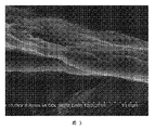
図3は、本発明の1つの実施例によるフッ化酸化グラフェンの走査型電子顕微鏡画像を示す。 FIG. 3 shows a scanning electron microscope image of fluorinated graphene oxide according to one embodiment of the present invention.
図4は、本発明の1つの実施例によるフッ化酸化グラフェン−カーボンナノチューブ複合材料の走査型電子顕微鏡画像を示す。 FIG. 4 shows a scanning electron microscope image of a graphene fluoride oxide-carbon nanotube composite material according to one embodiment of the present invention.
図5は、本発明の1つの実施例による窒化酸化グラフェンの走査型電子顕微鏡画像を示す。 FIG. 5 shows a scanning electron microscope image of graphene nitride oxide according to one embodiment of the present invention.
図6は、本発明の1つの実施例による窒化酸化グラフェン−カーボンナノチューブ複合材料の走査型電子顕微鏡画像を示す。 FIG. 6 shows a scanning electron microscope image of a graphene nitride oxide-carbon nanotube composite material according to one embodiment of the present invention.
本発明の目的、特徴、利点をより理解し易くするために、以下では本発明の具体的な実施方法が図面とともに詳細に説明される。以下の説明中においては、多くの具体的な詳細説明が、本発明を完全に理解するために記載される。本発明について他の多くの方法が実施可能であり、当業者は本発明の範囲を超えない限りにおいて、変形や変更を実施することができるため、本発明は、以下に記載される具体的実施例に限定されるものではない。 In order to make the objects, features and advantages of the present invention more comprehensible, specific embodiments of the present invention will be described in detail below with reference to the drawings. In the following description, numerous specific details are set forth in order to provide a thorough understanding of the present invention. Many other methods are possible for the present invention, and those skilled in the art can implement variations and modifications without departing from the scope of the present invention. It is not limited to examples.
一実施例としてのグラフェン誘導体−カーボンナノチューブ複合材料は、グラフェン誘導体と、カーボンナノチューブを1〜5:1の質量比で含む。グラフェン誘導体−カーボンナノチューブ複合材料中のグラフェン誘導体とカーボンナノチューブは互いに浸透し、絡み合い、連続ネットワーク構造を構成する。 The graphene derivative-carbon nanotube composite material as an example includes the graphene derivative and the carbon nanotube in a mass ratio of 1 to 5: 1. The graphene derivative and the carbon nanotube in the graphene derivative-carbon nanotube composite material penetrate each other and entangle with each other to form a continuous network structure.
グラフェン誘導体の単一分子層の2次元構造は、層間水を除去する乾燥工程において、容易に凝集され、積層され、巻くように曲げられる、或いは、高度に皺寄せされ、最終的に、比表面積の利用率は大いに低下することになる。カーボンナノチューブとグラフェン誘導体では、構造と性能において多くの類似性があるので、グラフェン誘導体のレイヤにカーボンナノチューブを挿入することができ、或いは、カーボンナノチューブとグラフェン誘導体の官能基を互いに反応させることができ、グラフェン誘導体の表面にカーボンナノチューブをグラフト化することができ、これにより、グラフェンの層を互いに分離させ、これをもって乾燥後のグラフェン誘導体の比表面積を高めることができ、グラフェン誘導体の凝集と積層を避けることができ、これにより、スーパーコンデンサのキャパシタンスを一層増加させることが図られる。 The two-dimensional structure of a single molecular layer of graphene derivative is easily agglomerated, laminated, bent into a roll, or highly gathered in the drying process to remove interlaminar water, and finally the specific surface area The utilization rate will be greatly reduced. Since carbon nanotubes and graphene derivatives have many similarities in structure and performance, carbon nanotubes can be inserted into the graphene derivative layer, or the functional groups of carbon nanotubes and graphene derivatives can react with each other The carbon nanotubes can be grafted onto the surface of the graphene derivative, thereby separating the graphene layers from each other, thereby increasing the specific surface area of the graphene derivative after drying, and agglomeration and lamination of the graphene derivative Which can be avoided, thereby further increasing the capacitance of the supercapacitor.
グラフェン誘導体は、フッ化酸化グラフェン、または、窒化酸化グラフェンとすることができる。カーボンナノチューブは、5nmから200nmの直径と、0.1μmから100μmの長さを有する中空の管状の炭素材料とすることができる。電極材料とした場合、フッ化酸化グラフェンの放電容量は、酸化グラファイトと比較して、大いに高いものとなる。放電電流密度が0.5mA/cm2(1M LiClO4−PC)であるときの放電容量は675mAh/gであり、エネルギ密度は1420Wh/kgである。酸化グラフェンに窒素をドープして窒素ドープ酸化グラフェンが生成されることで、安定性が向上するだけでなく、伝導性能をも高めることができ、また、明らかな生物n型効果(a clear biological n−type effect)が出現する。 The graphene derivative can be fluorinated graphene oxide or nitrided graphene oxide. The carbon nanotube can be a hollow tubular carbon material having a diameter of 5 nm to 200 nm and a length of 0.1 μm to 100 μm. When an electrode material is used, the discharge capacity of graphene fluoride oxide is much higher than that of graphite oxide. When the discharge current density is 0.5 mA / cm 2 (1M LiClO 4 —PC), the discharge capacity is 675 mAh / g, and the energy density is 1420 Wh / kg. Nitrogen is doped into graphene oxide to generate nitrogen-doped graphene oxide, so that not only the stability is improved, but also the conduction performance can be improved, and an obvious biological n-type effect (a clear biological n -Type effect) appears.
図1に示すように、グラフェン誘導体−カーボンナノチューブ複合材料の作製方法は、以下のステップを含む。 As shown in FIG. 1, the manufacturing method of a graphene derivative-carbon nanotube composite material includes the following steps.
ステップS110:グラフェン誘導体とカーボンナノチューブを提供、又は、作製する。 Step S110: Providing or producing a graphene derivative and a carbon nanotube.
グラフェン誘導体は、フッ化酸化グラフェン、または、窒化酸化グラフェンとすることができる。 The graphene derivative can be fluorinated graphene oxide or nitrided graphene oxide.
フッ化酸化グラフェンは、従来の方法により作製することができる。好ましくは、以下の方法で作製できる。 Fluorinated graphene oxide can be manufactured by a conventional method. Preferably, it can be produced by the following method.
ステップS111:酸化グラフェンを、グラファイトを使用して作製する。 Step S111: Graphene oxide is produced using graphite.
(a)グラファイト、過硫酸カリウム、及び、リン五酸化物を、質量比2〜10:1:1として、80℃〜120℃の温度の濃硫酸に加え、一様に攪拌した後に自然冷却し、混合物が中性になるまで洗浄し、乾燥し、混合物を得る。グラファイトは、好ましくは、フレーク状のグラファイトとする。 (A) Graphite, potassium persulfate, and phosphorus pentoxide are added to concentrated sulfuric acid at a temperature of 80 ° C. to 120 ° C. in a mass ratio of 2 to 10: 1: 1, and are naturally cooled after stirring uniformly. Wash until the mixture is neutral and dry to obtain a mixture. The graphite is preferably flaky graphite.
(b)混合物とカリウム過マンガン酸塩が濃硫酸に加えられ、混合溶液の温度は、15℃〜20℃の温度に保持され、その後、25℃〜35℃の温度のオイルバスに1時間から3時間おかれ、脱イオン水と過酸化水素溶液が加えられて反応が行われ、濾過がされ、固形物が収集される。 (B) The mixture and potassium permanganate are added to concentrated sulfuric acid, and the temperature of the mixed solution is maintained at a temperature of 15 ° C. to 20 ° C., and then placed in an oil bath at a temperature of 25 ° C. to 35 ° C. for 1 hour. After 3 hours, deionized water and hydrogen peroxide solution are added to react, filtered, and solids collected.
(c)固形物は、希塩酸で洗浄され、乾燥され、酸化グラファイトが得られる。 (C) The solid is washed with dilute hydrochloric acid and dried to obtain graphite oxide.
(d)酸化グラファイトは、脱イオン水に加えられ、1時間超音波振動がなされ、均一に分散された酸化グラフェンコロイド溶液が得られ、濾過され、固形物が収集され、真空乾燥され、酸化グラフェンを得る。 (D) Graphite oxide is added to deionized water and subjected to ultrasonic vibration for 1 hour to obtain a uniformly dispersed graphene oxide colloidal solution, filtered, solids collected, vacuum dried, and graphene oxide Get.
ステップS112:酸化グラフェンと、N2とF2の混成ガスを、20℃から200℃までの温度において、0.5時間から24時間反応させ、フッ化酸化グラフェンを得る。 Step S112: Graphene oxide and a mixed gas of N 2 and F 2 are reacted at a temperature from 20 ° C. to 200 ° C. for 0.5 to 24 hours to obtain fluorinated graphene oxide.
好ましくは、S111にて得られた酸化グラフェンは反応器に置かれ、N2とF2を含む混合ガス(F2の体積分率は5%から30%である)が導入され、加熱して温度を20℃〜200℃に維持し、0.5時間から24時間の反応により、酸化グラフェンとF2を反応させ、F部分がOにより置換され、フッ化酸化グラフェンが得られる。 Preferably, the graphene oxide obtained in S111 is placed in a reactor, and a mixed gas containing N 2 and F 2 (the volume fraction of F 2 is 5% to 30%) is introduced and heated. The temperature is maintained at 20 ° C. to 200 ° C., and the graphene oxide and F 2 are reacted by a reaction for 0.5 to 24 hours, and the F portion is replaced with O, whereby fluorinated graphene oxide is obtained.
より好適な実施例では、混合ガス中のF2の体積分率は10%とし、反応温度は100℃とし、反応時間は1時間とする。 In a more preferred embodiment, the volume fraction of F 2 in the mixed gas is 10%, the reaction temperature is 100 ° C., and the reaction time is 1 hour.
窒化酸化グラフェンは、従来の方法により作製することができる。好ましくは、以下の方法により作製することができる。 The graphene nitride oxide can be manufactured by a conventional method. Preferably, it can be produced by the following method.
ステップS111’:グラファイトを使用して、酸化グラフェンが作製される。 Step S111 ': Graphene oxide is produced using graphite.
このステップの過程は、ステップS111と実質的に同じである。 The process of this step is substantially the same as step S111.
ステップS112’:ステップS111’で得られた酸化グラフェンをアンモニア雰囲気において、10℃/分の昇温速度にて500℃〜800℃に至らせ、2時間保温し、室温に冷却し、窒化酸化グラフェンを得る。 Step S112 ′: The graphene oxide obtained in step S111 ′ is brought to 500 ° C. to 800 ° C. at a temperature rising rate of 10 ° C./min in an ammonia atmosphere, kept for 2 hours, cooled to room temperature, and graphene nitride oxide oxide Get.
好ましくは、酸化グラフェンのサンプルを加熱炉におき、高純度のアンモニアを導入し、アンモニアの導入流量を80mL/分とし、5〜10分間アンモニアを導入し、管式炉中の空気を排出し、その後、加熱炉に対して加熱を行い、温度を500℃〜800℃の反応温度になるまで10℃/分の速度で加熱し、2時間保持する。反応が終わった後、アンモニア雰囲気の下で室温に至るまで冷却され、窒素がドープされた窒化酸化グラフェンを得る。 Preferably, a graphene oxide sample is placed in a heating furnace, high-purity ammonia is introduced, the flow rate of ammonia is 80 mL / min, ammonia is introduced for 5 to 10 minutes, and the air in the tube furnace is discharged, Thereafter, the heating furnace is heated and heated at a rate of 10 ° C./min until the temperature reaches a reaction temperature of 500 ° C. to 800 ° C. and held for 2 hours. After the reaction is completed, the resultant is cooled to room temperature under an ammonia atmosphere to obtain nitrogen-doped graphene oxide doped with nitrogen.
カーボンナノチューブは、従来の方法により作製することができる。好ましくは、カーボンナノチューブは、5nmから200nmの直径と、0.1μmから100μmの長さを有する中空の管状の炭素材料とする。 Carbon nanotubes can be produced by conventional methods. Preferably, the carbon nanotube is a hollow tubular carbon material having a diameter of 5 nm to 200 nm and a length of 0.1 μm to 100 μm.
ステップS120:ステップS110にて得られたグラフェン誘導体とカーボンナノチューブが、アルコール分散剤に加えられ、超音波分散を行い、安定した懸濁液を得る。 Step S120: The graphene derivative and the carbon nanotube obtained in step S110 are added to the alcohol dispersant, and ultrasonic dispersion is performed to obtain a stable suspension.
好ましくは、グラフェン誘導体とカーボンナノチューブが1〜5:1の質量比でアルコール分散剤に加えられ、120〜150分間、超音波分散を行い、両者を均一に分散させ、安定した懸濁液を得る。 Preferably, the graphene derivative and the carbon nanotube are added to the alcohol dispersant in a mass ratio of 1 to 5: 1, and ultrasonic dispersion is performed for 120 to 150 minutes to uniformly disperse both to obtain a stable suspension. .
好ましくは、アルコール分散剤は、エタノール、エチレングリコール、およびイソプロパノールのいずれか一つである。 Preferably, the alcohol dispersant is any one of ethanol, ethylene glycol, and isopropanol.
ステップS130:懸濁液は濾過され、固形物が乾燥され、室温に冷却され、グラフェン誘導体−カーボンナノチューブ複合材料を得る。 Step S130: The suspension is filtered and the solid is dried and cooled to room temperature to obtain a graphene derivative-carbon nanotube composite material.
好ましくは、固形物は、真空乾燥箱中において、50℃〜80℃の温度で48時間〜56時間放置され、室温に冷却され、グラフェン誘導体−カーボンナノチューブ複合材料を得る。 Preferably, the solid is left in a vacuum drying box at a temperature of 50 ° C. to 80 ° C. for 48 hours to 56 hours and cooled to room temperature to obtain a graphene derivative-carbon nanotube composite material.
上述の作製方法には、以下の利点がある。 The above manufacturing method has the following advantages.
(1)フッ素または窒素がドープされた酸化グラフェンは、酸化グラフェンを通じて容易に作製することができ、酸化グラフェンの安定性を高めることができる。 (1) Graphene oxide doped with fluorine or nitrogen can be easily manufactured through graphene oxide, and the stability of graphene oxide can be improved.
(2)酸素原子が置換され、フッ素または窒素でドープすることで、電極材料の容量を顕著に高めることができる。このグラフェン誘導体−カーボンナノチューブ複合材料により作製されたスーパーコンデンサの充電比容量は、99F/g〜112F/gであり、放電比容量は96F/g〜110F/gであり、充放電効率は、97%〜99.5%である。 (2) The capacity of the electrode material can be significantly increased by replacing oxygen atoms and doping with fluorine or nitrogen. The supercapacitor made of this graphene derivative-carbon nanotube composite material has a charge specific capacity of 99 F / g to 112 F / g, a discharge specific capacity of 96 F / g to 110 F / g, and a charge / discharge efficiency of 97 % To 99.5%.
(3)グラフェン誘導体とカーボンナノチューブ複合体は、混成し、浸透した構造を構成し、グラフェン誘導体の凝集と積層形成を同時に防ぎ、これによりさらによいことに、グラフェン誘導体とカーボンナノチューブの構造と機能における相補性が可能となり、複合材料の導電性を高める。 (3) Graphene derivatives and carbon nanotube composites form a hybridized and permeated structure, preventing aggregation and stacking of graphene derivatives at the same time, and even better, in the structure and function of graphene derivatives and carbon nanotubes Complementarity is possible, increasing the conductivity of the composite material.
以下では具体的な実施例を用いて説明する。以下のすべての試薬は、分析グレードのものである。 In the following, description will be made using specific examples. All reagents below are analytical grade.
実施例1 Example 1
(1)純度99.5%の、天然のフレーク状のグラファイトが提供される。 (1) Natural flaky graphite having a purity of 99.5% is provided.
(2)修正ハマー法(modified−Hummers method)により、酸化グラファイトが作製される。具体的なステップとして、20gの50メッシュグラファイト粉、10gの過硫酸カリウム、および10gのリン五酸化物が、80℃の温度で濃硫酸に加えられ、混合物を均一に攪拌して、6時間以上冷却し、中性になるまで洗浄し、乾燥し、サンプルを得る。乾燥されたサンプルは、230mLの濃硫酸に温度0度において加えられ、60gの過マンガン酸カリウムが加えられ、混合物の温度は20℃以下で維持され、その後、2時間、オイルバスにおいて35℃の温度で保持され、920mLの脱イオン水がゆっくりと加えられる。15分後に、2.8Lの脱イオン水(濃度30%の50mLの過酸化水素を含む)が加えられ、混合物の色が明るい黄色に変化した際に、熱濾過を行い、濃度10%の5Lの塩酸で洗浄し、濾過を行い、60℃で48時間真空乾燥を行い、酸化グラファイトを得る。 (2) Graphite oxide is produced by a modified-Hummers method. As a specific step, 20 g of 50 mesh graphite powder, 10 g of potassium persulfate, and 10 g of phosphorus pentoxide are added to concentrated sulfuric acid at a temperature of 80 ° C., and the mixture is stirred uniformly for over 6 hours. Cool, wash until neutral, and dry to obtain a sample. The dried sample is added to 230 mL of concentrated sulfuric acid at a temperature of 0 ° C., 60 g of potassium permanganate is added, and the temperature of the mixture is maintained below 20 ° C., then 2 hours at 35 ° C. in an oil bath. Hold at temperature and 920 mL of deionized water is added slowly. After 15 minutes, 2.8 L of deionized water (containing 50 mL of hydrogen peroxide at a concentration of 30%) was added, and when the color of the mixture changed to light yellow, hot filtration was performed and 5 L of a concentration of 10% was obtained. Washed with hydrochloric acid, filtered, and vacuum dried at 60 ° C. for 48 hours to obtain graphite oxide.
(3)20gの酸化グラファイトと200mLの脱イオン水がビーカーに加えられ、1時間超音波分散され、黄褐色の均一な透明溶液を得て、均一に分散された酸化グラフェンを含むコロイド溶液を形成し、濾過し、60℃で48時間真空乾燥を行い、酸化グラフェンを得る。 (3) 20 g of graphite oxide and 200 mL of deionized water are added to a beaker and ultrasonically dispersed for 1 hour to obtain a tan-colored uniform transparent solution to form a colloidal solution containing uniformly dispersed graphene oxide Filtered and vacuum dried at 60 ° C. for 48 hours to obtain graphene oxide.
(4)乾燥した酸化グラフェンを反応器に置き、4時間乾燥窒素を導入し、その後、フッ素を導入して酸化グラフェンと100℃下で1時間反応させ、フッ化酸化グラフェンを得る。混成ガスの中のフッ素の体積分率は10%である。 (4) Place the dried graphene oxide in a reactor, introduce dry nitrogen for 4 hours, and then introduce fluorine and react with graphene oxide at 100 ° C. for 1 hour to obtain fluorinated graphene oxide. The volume fraction of fluorine in the hybrid gas is 10%.
(5)100mgのフッ化酸化グラフェンと100mgのカーボンナノチューブが500mLのエタノールに加えられ、カーボンナノチューブの直径を5nmとし、長さは0.1μmとし、混合液が120分間超音波分散され、両者が均一に分散された安定した懸濁液を得る。懸濁液は濾過され、50℃で48時間真空乾燥され、フッ化酸化グラフェン−カーボンナノチューブ複合材料を得る。 (5) 100 mg of graphene fluoride oxide and 100 mg of carbon nanotubes are added to 500 mL of ethanol, the diameter of the carbon nanotubes is 5 nm, the length is 0.1 μm, and the mixture is ultrasonically dispersed for 120 minutes. A uniformly dispersed stable suspension is obtained. The suspension is filtered and vacuum dried at 50 ° C. for 48 hours to obtain a graphene oxide fluoride-carbon nanotube composite.
図2は、実施例1のカーボンナノチューブの走査型電子顕微鏡(SEM)画像を示す。図3は、実施例1のフッ化酸化グラフェンの走査型電子顕微鏡(SEM)画像を示す。図4は、実施例1のフッ化酸化グラフェン−カーボンナノチューブ複合材料の走査型電子顕微鏡(SEM)画像を示す。図2〜図4により明らかなように、単一のカーボンナノチューブ、或いは、単一のフッ化酸化グラフェンにおける凝集の現象が見られるが、酸化グラフェン−カーボンナノチューブ複合材料においてはフッ化酸化グラフェンがカーボンナノチューブにより均一に分離され、積層化や凝集化の現象は発生していない。 FIG. 2 shows a scanning electron microscope (SEM) image of the carbon nanotube of Example 1. FIG. 3 shows a scanning electron microscope (SEM) image of graphene fluoride oxide of Example 1. 4 shows a scanning electron microscope (SEM) image of the graphene oxide fluoride-carbon nanotube composite material of Example 1. FIG. As apparent from FIGS. 2 to 4, a phenomenon of aggregation is observed in a single carbon nanotube or a single graphene oxide oxide, but in the graphene oxide-carbon nanotube composite material, the graphene oxide oxide is carbon. They are uniformly separated by the nanotubes, and no layering or aggregation phenomenon occurs.
実施例2 Example 2
(1)純度99.5%の、天然のフレーク状のグラファイトが提供される。 (1) Natural flaky graphite having a purity of 99.5% is provided.
(2)修正ハマー法(modified−Hummers method)により、酸化グラファイトが作製される。具体的なステップとして、20gの50メッシュグラファイト粉、10gの過硫酸カリウム、および10gのリン五酸化物が、80℃の温度で濃硫酸に加えられ、混合物を均一に攪拌して、6時間以上冷却し、中性になるまで洗浄し、乾燥し、サンプルを得る。乾燥されたサンプルは、230mLの濃硫酸に温度0度において加えられ、60gの過マンガン酸カリウムが加えられ、混合物の温度は20℃以下で維持され、その後、2時間、オイルバスにおいて35℃の温度で保持され、920mLの脱イオン水がゆっくりと加えられる。15分後に、2.8Lの脱イオン水(濃度30%の50mLの過酸化水素を含む)が加えられ、混合物の色が明るい黄色に変化した際に、熱濾過を行い、濃度10%の5Lの塩酸で洗浄し、濾過し、60℃で48時間真空乾燥を行い、酸化グラファイトを得る。 (2) Graphite oxide is produced by a modified-Hummers method. As a specific step, 20 g of 50 mesh graphite powder, 10 g of potassium persulfate, and 10 g of phosphorus pentoxide are added to concentrated sulfuric acid at a temperature of 80 ° C., and the mixture is stirred uniformly for over 6 hours. Cool, wash until neutral, and dry to obtain a sample. The dried sample is added to 230 mL of concentrated sulfuric acid at a temperature of 0 ° C., 60 g of potassium permanganate is added, and the temperature of the mixture is maintained below 20 ° C., then 2 hours at 35 ° C. in an oil bath. Hold at temperature and 920 mL of deionized water is added slowly. After 15 minutes, 2.8 L of deionized water (containing 50 mL of hydrogen peroxide at a concentration of 30%) was added, and when the color of the mixture changed to light yellow, hot filtration was performed and 5 L of a concentration of 10% was obtained. After washing with hydrochloric acid, filtering and vacuum drying at 60 ° C. for 48 hours, graphite oxide is obtained.
(3)20gの酸化グラファイトと200mLの脱イオン水がビーカーに加えられ、1時間超音波分散され、黄褐色の均一な透明溶液を得て、均一に分散された酸化グラフェンを含むコロイド溶液を形成し、濾過し、60℃で48時間真空乾燥を行い、酸化グラフェンを得る。 (3) 20 g of graphite oxide and 200 mL of deionized water are added to a beaker and ultrasonically dispersed for 1 hour to obtain a tan-colored uniform transparent solution to form a colloidal solution containing uniformly dispersed graphene oxide Filtered and vacuum dried at 60 ° C. for 48 hours to obtain graphene oxide.
(4)酸化グラフェンを加熱炉の管の中におき、高純度のアンモニアを導入し、アンモニアの流量はガス流量計で制御され、アンモニアの導入流量を80mL/分とし、10分間アンモニアを導入し、管式炉中の空気を排出し、その後、加熱炉に対して加熱を行い、温度を800℃の反応温度になるまで10℃/分の速度で加熱し、2時間保持する。反応が終わった後、アンモニア雰囲気の下で室温に至るまで冷却され、窒素がドープされた窒化酸化グラフェンを炉から取り出す。 (4) Graphene oxide is placed in the furnace tube, high-purity ammonia is introduced, the ammonia flow rate is controlled by a gas flow meter, the ammonia introduction flow rate is 80 mL / min, and ammonia is introduced for 10 minutes. Then, the air in the tube furnace is exhausted, and then the heating furnace is heated, and the temperature is heated at a rate of 10 ° C./min until the reaction temperature reaches 800 ° C., and held for 2 hours. After the reaction is completed, the graphene nitride oxide that is cooled to room temperature under an ammonia atmosphere and doped with nitrogen is taken out of the furnace.
(5)200mgの窒素がドープされた酸化グラフェンと100mgのカーボンナノチューブが500mLのエチレングリコールに加えられ、カーボンナノチューブの直径を200nmとし、長さを100μmとし、混合液が150分間超音波分散され、両者が均一に分散された安定した懸濁液を得る。懸濁液は濾過され、50℃で48時間真空乾燥され、窒素がドープされた酸化グラフェン−カーボンナノチューブ複合材を得る。 (5) 200 mg of nitrogen-doped graphene oxide and 100 mg of carbon nanotubes are added to 500 mL of ethylene glycol, the diameter of the carbon nanotubes is 200 nm, the length is 100 μm, and the mixture is ultrasonically dispersed for 150 minutes, A stable suspension in which both are uniformly dispersed is obtained. The suspension is filtered and vacuum dried at 50 ° C. for 48 hours to obtain a graphene oxide-carbon nanotube composite doped with nitrogen.
図5は、実施例2の窒素がドープされた酸化グラフェン−カーボンナノチューブ複合材料の走査型電子顕微(SEM)鏡画像を示す。図5により明らかなように、窒素がドープされた酸化グラフェンは凝集し、皺模様が現れた。図6は、実施例2の窒素がドープされた酸化グラフェン−カーボンナノチューブ複合材料の走査型電子顕微(SEM)鏡画像を示す。図6により明らかなように、窒素ドープ酸化グラフェン−カーボンナノチューブ複合材料において、窒素ドープ酸化グラフェンはカーボンナノチューブにより均一に分離され、積層化や凝集化の現象は発生しない。 FIG. 5 shows a scanning electron microscopic (SEM) mirror image of the nitrogen-doped graphene oxide-carbon nanotube composite material of Example 2. As apparent from FIG. 5, the graphene oxide doped with nitrogen aggregates and a wrinkle pattern appears. 6 shows a scanning electron microscopic (SEM) mirror image of the nitrogen-doped graphene oxide-carbon nanotube composite material of Example 2. FIG. As is apparent from FIG. 6, in the nitrogen-doped graphene oxide-carbon nanotube composite material, the nitrogen-doped graphene oxide is uniformly separated by the carbon nanotubes, and the phenomenon of lamination or aggregation does not occur.
実施例3 Example 3
実施例1に従い、フッ化酸化グラフェンが準備される。 According to Example 1, fluorinated graphene oxide is prepared.
300mgのフッ化酸化グラフェンと100mgのカーボンナノチューブが500mLのエタノールに加えられ、カーボンナノチューブの直径を50nmとし、長さは30μmとし、混合液が120分間超音波分散され、両者が均一に分散された安定した懸濁液を得る。懸濁液は濾過され、80℃で56時間真空乾燥され、グラフェン誘導体−カーボンナノチューブ複合材料を得る。 300 mg of graphene fluoride oxide and 100 mg of carbon nanotubes were added to 500 mL of ethanol, the diameter of the carbon nanotubes was 50 nm, the length was 30 μm, the mixture was ultrasonically dispersed for 120 minutes, and both were uniformly dispersed A stable suspension is obtained. The suspension is filtered and vacuum dried at 80 ° C. for 56 hours to obtain a graphene derivative-carbon nanotube composite material.
実施例4 Example 4
実施例2に従い、窒素がドープされた酸化グラフェンが準備される。 According to Example 2, graphene oxide doped with nitrogen is prepared.
500mgの窒素がドープされた酸化グラフェンと100mgのカーボンナノチューブが500mLのエチレングリコールに加えられ、カーボンナノチューブの直径を100nmとし、長さを50μmとし、混合液が150分間超音波分散され、両者が均一に分散された安定した懸濁液を得る。懸濁液は濾過され、60℃で50時間真空乾燥され、窒素がドープされた酸化グラフェン−カーボンナノチューブ複合材料を得る。 Graphene oxide doped with 500 mg of nitrogen and 100 mg of carbon nanotubes are added to 500 mL of ethylene glycol, the diameter of the carbon nanotubes is 100 nm, the length is 50 μm, and the mixture is ultrasonically dispersed for 150 minutes. A stable suspension dispersed in is obtained. The suspension is filtered and vacuum dried at 60 ° C. for 50 hours to obtain a graphene oxide-carbon nanotube composite material doped with nitrogen.
実施例1乃至実施例4に従い、得られたグラフェン誘導体−カーボンナノチューブ複合材料は、それぞれスーパーコンデンサの電極材料として使用され、得られたスーパーコンデンサの充放電比容量及び充放電効率は表1に示される。
表1:スーパーコンデンサの充放電比容量及び充放電効率

Table 1: Charge / discharge specific capacity and charge / discharge efficiency of super capacitor
表1からわかるように、上述した実施例のグラフェン誘導体−カーボンナノチューブ複合材料で作製されたスーパーコンデンサの充放電比容量は、比較的大きく、充放電効率は比較的高い。 As can be seen from Table 1, the charge / discharge specific capacity of the supercapacitor made of the graphene derivative-carbon nanotube composite material of the above-described embodiment is relatively large and the charge / discharge efficiency is relatively high.
上記のように、各実施例は本発明のいくつかの実施形態について具体的且つ詳しく説明されているが、本発明の開示を制限するものと理解されるものではない。指摘されるべきことは、本発明は、この技術分野に精通した者により本発明の主旨を逸脱しない範囲での若干の変更や修正をすることができるということである。従って、本発明の特許の保護範囲は、添付の特許請求の記載に基づくべきである。
As described above, each example has been described with particularity and detail for some embodiments of the present invention, but is not to be construed as limiting the disclosure of the present invention. It should be pointed out that the present invention can be slightly changed or modified by those skilled in the art without departing from the spirit of the present invention. Therefore, the protection scope of the patent of the present invention should be based on the appended claims.
Claims (6)
グラフェン誘導体とカーボンナノチューブを1〜5:1の質量比で含み、前記グラフェン誘導体−カーボンナノチューブ複合材料中のグラフェン誘導体とカーボンナノチューブは互いに浸透し、絡み合い、連続ネットワーク構造を構成しており、
前記グラフェン誘導体は、窒化酸化グラフェンであり、
前記グラフェン誘導体の表面に前記カーボンナノチューブがグラフト化されることで、前記グラフェンの層が互いに分離され、
前記カーボンナノチューブは、5nmから200nmの直径を有し、0.1μmから100μmの長さを有する、中空の管状の炭素材料である、
グラフェン誘導体−カーボンナノチューブ複合材料。 A graphene derivative-carbon nanotube composite material,
The graphene derivative and the carbon nanotube are included in a mass ratio of 1 to 5: 1, and the graphene derivative and the carbon nanotube in the graphene derivative-carbon nanotube composite material penetrate each other and are entangled to form a continuous network structure .
The graphene derivative, Ri oxynitride graphene der,
By grafting the carbon nanotubes on the surface of the graphene derivative, the graphene layers are separated from each other,
The carbon nanotubes have a diameter of 200nm from 5 nm, has a length of 100μm from 0.1 [mu] m, Ru carbon material der hollow tubular,
Graphene derivative-carbon nanotube composite material.
前記グラフェン誘導体は、前記カーボンナノチューブとの混合前に準備されたフッ化酸化グラフェン、又は、窒化酸化グラフェンであり、
前記グラフェン誘導体の表面に前記カーボンナノチューブがグラフト化されることで、前記グラフェンの層が互いに分離され、
前記カーボンナノチューブは、5nmから200nmの直径を有し、0.1μmから100μmの長さを有する、中空の管状の炭素材料である、
グラフェン誘導体−カーボンナノチューブ複合材料の作製方法であって、
前記グラフェン誘導体と前記カーボンナノチューブをアルコール分散剤に加え、120〜150分間、超音波分散を行い、安定した懸濁液を得るステップ1と、
懸濁液を濾過して固形物を得て、固形物を乾燥し室温まで冷却し、グラフェン誘導体−カーボンナノチューブ複合材料を得るステップ2を含む、
グラフェン誘導体−カーボンナノチューブ複合材料の作製方法。 The graphene derivative and the carbon nanotube are included at a mass ratio of 1 to 5: 1, and the graphene derivative and the carbon nanotube in the graphene derivative-carbon nanotube composite material penetrate each other and are entangled to form a continuous network structure.
The graphene derivative is fluorinated graphene oxide prepared before mixing with the carbon nanotubes, or oxynitride graphene,
By grafting the carbon nanotubes on the surface of the graphene derivative, the graphene layers are separated from each other,
The carbon nanotube is a hollow tubular carbon material having a diameter of 5 nm to 200 nm and a length of 0.1 μm to 100 μm.
A method for producing a graphene derivative-carbon nanotube composite material,
Step 1 of adding the graphene derivative and the carbon nanotube to an alcohol dispersant and performing ultrasonic dispersion for 120 to 150 minutes to obtain a stable suspension;
Filtering the suspension to obtain a solid, comprising drying the solid and cooling to room temperature to obtain a graphene derivative-carbon nanotube composite material, step 2;
A method for manufacturing a graphene derivative-carbon nanotube composite material.
グラファイトを使用して、酸化グラフェンを作製し、
酸化グラフェンと、N2とF2の混成ガスを、20℃から200℃までの温度において、0.5時間から24時間反応させ、フッ化酸化グラフェンを得る、ことにより作製される、
ことを特徴とする請求項2乃至4のいずれか一項に記載のグラフェン誘導体−カーボンナノチューブ複合材料の作製方法。 The graphene fluoride oxide is
Using graphite, make graphene oxide,
It is produced by reacting graphene oxide and a mixed gas of N2 and F2 at a temperature from 20 ° C. to 200 ° C. for 0.5 to 24 hours to obtain fluorinated graphene oxide.
The method for producing a graphene derivative-carbon nanotube composite material according to any one of claims 2 to 4, wherein:
グラファイトを使用して、酸化グラフェンを調合し、
酸化グラフェンをアンモニア雰囲気において、10℃/分の昇温速度にて500℃〜800℃に至らせ、2時間保温し、室温に冷却し、窒化酸化グラフェンを得る、ことにより作製される、
ことを特徴とする請求項2乃至4のいずれか一項に記載のグラフェン誘導体−カーボンナノチューブ複合材料の作製方法。 The graphene nitride oxide is
Graphite oxide is prepared using graphite,
It is produced by bringing graphene oxide in an ammonia atmosphere to a temperature of 500 ° C. to 800 ° C. at a temperature rising rate of 10 ° C./min, keeping it warm for 2 hours, and cooling to room temperature to obtain graphene nitride oxide.
The method for producing a graphene derivative-carbon nanotube composite material according to any one of claims 2 to 4, wherein:
Applications Claiming Priority (1)
| Application Number | Priority Date | Filing Date | Title |
|---|---|---|---|
| PCT/CN2010/080531 WO2012088697A1 (en) | 2010-12-30 | 2010-12-30 | Graphene ramification-carbon nanotube composite material and preparation method thereof |
Publications (3)
| Publication Number | Publication Date |
|---|---|
| JP2014505650A JP2014505650A (en) | 2014-03-06 |
| JP2014505650A5 JP2014505650A5 (en) | 2015-04-30 |
| JP5775603B2 true JP5775603B2 (en) | 2015-09-09 |
Family
ID=46382214
Family Applications (1)
| Application Number | Title | Priority Date | Filing Date |
|---|---|---|---|
| JP2013546556A Active JP5775603B2 (en) | 2010-12-30 | 2010-12-30 | Graphene derivative-carbon nanotube composite material and manufacturing method thereof |
Country Status (5)
| Country | Link |
|---|---|
| US (1) | US20130252499A1 (en) |
| EP (1) | EP2660192B1 (en) |
| JP (1) | JP5775603B2 (en) |
| CN (1) | CN103153843B (en) |
| WO (1) | WO2012088697A1 (en) |
Families Citing this family (41)
| Publication number | Priority date | Publication date | Assignee | Title |
|---|---|---|---|---|
| CN102926272B (en) * | 2012-10-09 | 2015-02-11 | 重庆大学 | Process for preparing biomedical graphene oxide paper |
| JP2014114205A (en) * | 2012-11-14 | 2014-06-26 | Toshiba Corp | Carbon material, method for producing the same, and electrochemical cell, oxygen reduction device and refrigerator using the same |
| JP2014225508A (en) * | 2013-05-15 | 2014-12-04 | 住友電気工業株式会社 | Electrode for electricity storage device, electricity storage device, and method for manufacturing electrode for electricity storage device |
| CA2911440C (en) * | 2013-05-23 | 2021-08-24 | Toray Industries, Inc. | Method for producing polyanionic positive electrode active material composite particles, and polyanionic positive electrode active material precursor-graphite oxide composite granulated bodies |
| WO2015126464A2 (en) * | 2013-10-11 | 2015-08-27 | The Regents Of The University Of California | Stacked multilayers of alternating reduced graphene oxide and carbon nanotubes for ultrathin planar supercapacitors |
| KR102139118B1 (en) * | 2013-11-05 | 2020-07-29 | 더 리전트 오브 더 유니버시티 오브 캘리포니아 | Graphene oxide and carbon nanotube ink and methods for producing the same |
| CN104627977B (en) * | 2013-11-07 | 2017-02-08 | 中国科学院苏州纳米技术与纳米仿生研究所 | Graphene oxide reinforced composite carbon nanopaper and production method thereof |
| JP6077134B2 (en) * | 2013-11-13 | 2017-02-08 | 本田技研工業株式会社 | Carbon fiber membrane |
| EP3116003B1 (en) * | 2014-02-28 | 2018-10-17 | National Institute for Materials Science | Lithium-ion supercapacitor using graphene-cnt hybrid electrode and method for manufacturing said lithium-ion supercapacitor |
| JP6289995B2 (en) | 2014-05-13 | 2018-03-07 | 株式会社東芝 | Negative electrode, negative electrode manufacturing method, and nonaqueous electrolyte battery |
| CN105244476A (en) * | 2014-06-11 | 2016-01-13 | 中国科学院苏州纳米技术与纳米仿生研究所 | Nitrogen-doped graphene-coated nanometer sulfur cathode composite material, and preparation method and applications thereof |
| WO2016141414A1 (en) * | 2015-03-11 | 2016-09-15 | The University Of Sydney | Electrocatalysts and electrochemical cells |
| CN104826581B (en) * | 2015-03-17 | 2017-12-19 | 北京大学 | A kind of ammonia processing porous carbon materials and its formaldehyde absorbing application |
| TWI594796B (en) * | 2015-05-08 | 2017-08-11 | Taiwan Carbon Nano Tech Corp | A method for manufacturing a three-dimensional mesh material with a catalyst function |
| JP7050667B2 (en) * | 2015-09-23 | 2022-04-08 | ナノテク インスツルメンツ インク | Monolith membrane of integrated highly oriented halogenated graphene |
| WO2017110295A1 (en) * | 2015-12-24 | 2017-06-29 | 国立研究開発法人物質・材料研究機構 | Manufacturing method for composite material of two-dimensional substance and fibrous substance |
| CN105551823A (en) * | 2016-02-02 | 2016-05-04 | 深圳市贝特瑞新能源材料股份有限公司 | Carbon-carbon composite electrode material, preparation method and application |
| KR102024897B1 (en) * | 2016-06-08 | 2019-09-24 | 주식회사 엘지화학 | Self-assembled composite with Carbon Nitride and Graphene Oxide, Manufacturing Method Thereof, Cathode Applying the same, And Lithium-Sulfur Battery Comprising The Same |
| CN106602012B (en) * | 2016-12-13 | 2020-05-26 | 上海交通大学 | Flexible thin film electrode and preparation method and application thereof |
| CN106783217B (en) * | 2017-01-16 | 2018-07-13 | 天津大学 | Method for efficiently preparing nitrogen-doped graphene carbon nanotube film |
| CN106970116B (en) * | 2017-03-20 | 2019-09-10 | 中国石油大学(华东) | The sensitive polyhedral cobaltosic oxide of a kind of pair of acetone-three-dimensional porous Graphene gel composite material film |
| CN107311659A (en) * | 2017-06-22 | 2017-11-03 | 李若明 | A kind of preparation method of graphite film/graphene composite film |
| CN109686897B (en) * | 2017-10-18 | 2020-08-11 | 清华大学 | Lithium-sulfur battery diaphragm |
| CN109686906B (en) * | 2017-10-18 | 2020-08-11 | 清华大学 | Lithium-sulfur battery |
| CN109686898B (en) * | 2017-10-18 | 2020-08-11 | 清华大学 | Lithium-sulfur battery diaphragm |
| JP7139627B2 (en) * | 2018-03-07 | 2022-09-21 | 日本ゼオン株式会社 | Nonwoven fabric and its manufacturing method |
| JP2019157283A (en) * | 2018-03-07 | 2019-09-19 | 日本ゼオン株式会社 | Non-woven fabric and manufacturing method thereof |
| CN110247028A (en) * | 2018-03-09 | 2019-09-17 | 广州墨羲科技有限公司 | A kind of nano wire/three-dimensional graphene composite material |
| CN108421082A (en) * | 2018-04-23 | 2018-08-21 | 闫金银 | The preparation method of graphene oxide wound dressing with antibacterial anti-scar double action |
| CN110713177A (en) * | 2018-07-11 | 2020-01-21 | 南开大学 | Carbon nano tube/graphene bulk phase composite material, preparation method and application thereof |
| CN109082329B (en) * | 2018-07-23 | 2021-04-20 | 江苏大学 | Ternary nano self-lubricating composite material and preparation method thereof |
| US11264228B2 (en) | 2018-10-09 | 2022-03-01 | Savannah River Nuclear Solutions, Llc | Method of making a carbon filament for thermal ionization |
| CN109370227B (en) * | 2018-10-24 | 2021-03-09 | 明朔(北京)电子科技有限公司 | Heat-conducting silicone grease |
| CN110699038B (en) * | 2019-09-17 | 2022-06-10 | 沈阳航空航天大学 | Preparation method of magnetic porous composite material with wide glass-transition temperature range |
| CN111659401B (en) * | 2020-06-30 | 2022-11-29 | 齐鲁工业大学 | Three-dimensional porous carbon nanotube graphene composite membrane and preparation method thereof |
| CN114621621A (en) * | 2020-12-14 | 2022-06-14 | 清华大学 | Light absorber prefabricated liquid and preparation method thereof |
| CN114624798B (en) * | 2020-12-14 | 2023-05-16 | 清华大学 | Light absorber and method for producing the same |
| CN113594404B (en) * | 2021-07-29 | 2022-06-24 | 贵州梅岭电源有限公司 | Preparation method of integrated carbon fluoride anode |
| KR102438675B1 (en) * | 2022-03-08 | 2022-09-01 | 한국지질자원연구원 | Raw material in the form of dough using two-dimensional material, manufacturing method thereof, and electronic material manufactured using the same |
| CN114836645B (en) * | 2022-04-06 | 2022-11-01 | 西北工业大学 | Preparation method of carbon nanotube-graphene hybrid porous preform with designable configuration |
| CN114927354B (en) * | 2022-05-25 | 2023-08-22 | 南京航空航天大学 | Nitrogen-doped manganese dioxide/graphene carbon nanotube electrode material and preparation method thereof |
Family Cites Families (13)
| Publication number | Priority date | Publication date | Assignee | Title |
|---|---|---|---|---|
| JPS62296877A (en) * | 1986-06-16 | 1987-12-24 | Ibiden Co Ltd | Immobilization carrier for cell or microorganism composed of carbon or graphite having modified surface |
| JPH06212110A (en) * | 1993-01-20 | 1994-08-02 | Mitsubishi Pencil Co Ltd | Recording material containing modified carbon |
| JPH08250117A (en) * | 1995-03-09 | 1996-09-27 | Shin Kobe Electric Mach Co Ltd | Carbon material for lithium secondary battery negative electrode, and manufacture thereof |
| JP4380282B2 (en) * | 2003-09-26 | 2009-12-09 | 富士ゼロックス株式会社 | Method for producing carbon nanotube composite structure |
| US7449133B2 (en) * | 2006-06-13 | 2008-11-11 | Unidym, Inc. | Graphene film as transparent and electrically conducting material |
| JP4062346B2 (en) * | 2006-08-17 | 2008-03-19 | 富士ゼロックス株式会社 | Carbon nanotube film, manufacturing method thereof, and capacitor using the same |
| US7892514B2 (en) * | 2007-02-22 | 2011-02-22 | Nanotek Instruments, Inc. | Method of producing nano-scaled graphene and inorganic platelets and their nanocomposites |
| WO2008113023A1 (en) * | 2007-03-14 | 2008-09-18 | California Institute Of Technology | High discharge rate batteries |
| US7875219B2 (en) * | 2007-10-04 | 2011-01-25 | Nanotek Instruments, Inc. | Process for producing nano-scaled graphene platelet nanocomposite electrodes for supercapacitors |
| CN101811690B (en) * | 2009-02-24 | 2012-02-29 | 国家纳米科学中心 | Method for forming carbon composite structure by using carbon nano tube and graphene |
| CN101575095B (en) * | 2009-05-26 | 2012-12-12 | 北京大学 | Method for preparing graphene |
| CN101712452B (en) * | 2009-11-20 | 2012-07-11 | 哈尔滨工程大学 | Composite material of nano graphite flakes, carbon nano tubes and transition metal oxides and preparation method |
| CN101734650B (en) * | 2009-12-23 | 2012-06-20 | 沈阳建筑大学 | Method for preparing graphene-carbon nano tube hybrid composite |
-
2010
- 2010-12-30 JP JP2013546556A patent/JP5775603B2/en active Active
- 2010-12-30 WO PCT/CN2010/080531 patent/WO2012088697A1/en active Application Filing
- 2010-12-30 CN CN201080069677.0A patent/CN103153843B/en active Active
- 2010-12-30 EP EP10861263.1A patent/EP2660192B1/en active Active
- 2010-12-30 US US13/990,113 patent/US20130252499A1/en not_active Abandoned
Also Published As
| Publication number | Publication date |
|---|---|
| EP2660192B1 (en) | 2017-12-20 |
| JP2014505650A (en) | 2014-03-06 |
| WO2012088697A1 (en) | 2012-07-05 |
| CN103153843B (en) | 2014-04-02 |
| EP2660192A1 (en) | 2013-11-06 |
| CN103153843A (en) | 2013-06-12 |
| EP2660192A4 (en) | 2016-12-07 |
| US20130252499A1 (en) | 2013-09-26 |
Similar Documents
| Publication | Publication Date | Title |
|---|---|---|
| JP5775603B2 (en) | Graphene derivative-carbon nanotube composite material and manufacturing method thereof | |
| Xu et al. | 3D hierarchical carbon-rich micro-/nanomaterials for energy storage and catalysis | |
| Lin et al. | Carbon nanotube sponges, aerogels, and hierarchical composites: synthesis, properties, and energy applications | |
| Janas et al. | Carbon nanotube fibers and films: synthesis, applications and perspectives of the direct-spinning method | |
| Meng et al. | Polymer composites of boron nitride nanotubes and nanosheets | |
| Xu et al. | Fullerene micro/nanostructures: controlled synthesis and energy applications | |
| Inagaki et al. | Nanocarbons––recent research in Japan | |
| Wan et al. | Low-temperature aluminum reduction of graphene oxide, electrical properties, surface wettability, and energy storage applications | |
| US9359675B2 (en) | Producing two-dimensional sandwich nanomaterials based on graphene | |
| Liu et al. | Macroscopic carbon nanotube assemblies: preparation, properties, and potential applications | |
| KR101999866B1 (en) | Nanoplate-nanotube composites, methods for production thereof and products obtained therefrom | |
| JP5747421B2 (en) | Graphene sheet film connected with carbon nanotube, method for producing the same, and graphene sheet capacitor using the same | |
| KR100912807B1 (en) | Method of fabrication for carbon nanotubes uniformly coated with Titanium dioxide | |
| Meng et al. | 2d crystal–based fibers: Status and challenges | |
| WO2014021257A1 (en) | Method for producing composite film comprising graphene and carbon nanotubes | |
| JP4900376B2 (en) | Method for treating carbon nanotubes | |
| US8070988B2 (en) | Nano-carbon hybrid structures | |
| US20060165988A1 (en) | Carbon nanoparticles and composite particles and process of manufacture | |
| KR20130097640A (en) | Method for producing two-dimensional sandwich nanomaterials based on graphene | |
| CN1747218A (en) | The lithium ion battery of incorporating carbon nanostructure materials | |
| Zhang et al. | Carbon nanotube: Controlled synthesis determines its future | |
| Li et al. | Facile one-step synthesis of N-doped carbon nanotubes/N-doped carbon nanofibers hierarchical composites by chemical vapor deposition | |
| Badawi et al. | A review of wearable supercapacitors fabricated from highly flexible conductive fiber materials | |
| KR102265375B1 (en) | Graphene powder doped with nitrogen with high concentration obtained using arc discharge, method for manufacturing the same and method for manufacturing graphene film | |
| Akbar et al. | Functionalization of carbon nanotubes: Manufacturing techniques and properties of customized nanocomponents for molecular-level technology |
Legal Events
| Date | Code | Title | Description |
|---|---|---|---|
| A977 | Report on retrieval |
Free format text: JAPANESE INTERMEDIATE CODE: A971007 Effective date: 20140624 |
|
| A131 | Notification of reasons for refusal |
Free format text: JAPANESE INTERMEDIATE CODE: A131 Effective date: 20140804 |
|
| A521 | Request for written amendment filed |
Free format text: JAPANESE INTERMEDIATE CODE: A523 Effective date: 20141030 |
|
| A131 | Notification of reasons for refusal |
Free format text: JAPANESE INTERMEDIATE CODE: A131 Effective date: 20150306 |
|
| A524 | Written submission of copy of amendment under article 19 pct |
Free format text: JAPANESE INTERMEDIATE CODE: A524 Effective date: 20150311 |
|
| TRDD | Decision of grant or rejection written | ||
| A01 | Written decision to grant a patent or to grant a registration (utility model) |
Free format text: JAPANESE INTERMEDIATE CODE: A01 Effective date: 20150622 |
|
| A61 | First payment of annual fees (during grant procedure) |
Free format text: JAPANESE INTERMEDIATE CODE: A61 Effective date: 20150703 |
|
| R150 | Certificate of patent or registration of utility model |
Ref document number: 5775603 Country of ref document: JP Free format text: JAPANESE INTERMEDIATE CODE: R150 |
|
| R250 | Receipt of annual fees |
Free format text: JAPANESE INTERMEDIATE CODE: R250 |
|
| R250 | Receipt of annual fees |
Free format text: JAPANESE INTERMEDIATE CODE: R250 |
|
| R250 | Receipt of annual fees |
Free format text: JAPANESE INTERMEDIATE CODE: R250 |
|
| R250 | Receipt of annual fees |
Free format text: JAPANESE INTERMEDIATE CODE: R250 |
|
| R250 | Receipt of annual fees |
Free format text: JAPANESE INTERMEDIATE CODE: R250 |