JP5641083B2 - Power control apparatus, power control method, program, and power control system - Google Patents
Power control apparatus, power control method, program, and power control system Download PDFInfo
- Publication number
- JP5641083B2 JP5641083B2 JP2013052439A JP2013052439A JP5641083B2 JP 5641083 B2 JP5641083 B2 JP 5641083B2 JP 2013052439 A JP2013052439 A JP 2013052439A JP 2013052439 A JP2013052439 A JP 2013052439A JP 5641083 B2 JP5641083 B2 JP 5641083B2
- Authority
- JP
- Japan
- Prior art keywords
- power
- power control
- amount
- target
- reception
- Prior art date
- Legal status (The legal status is an assumption and is not a legal conclusion. Google has not performed a legal analysis and makes no representation as to the accuracy of the status listed.)
- Active
Links
- 238000000034 method Methods 0.000 title claims description 20
- 230000005540 biological transmission Effects 0.000 claims description 78
- 238000010248 power generation Methods 0.000 claims description 34
- 238000012545 processing Methods 0.000 claims description 21
- 230000008569 process Effects 0.000 claims description 10
- 238000005259 measurement Methods 0.000 claims description 8
- 238000004891 communication Methods 0.000 description 12
- 230000008859 change Effects 0.000 description 6
- 238000010586 diagram Methods 0.000 description 6
- 238000007599 discharging Methods 0.000 description 6
- 238000005516 engineering process Methods 0.000 description 3
- 238000012935 Averaging Methods 0.000 description 2
- 239000000284 extract Substances 0.000 description 2
- 230000036651 mood Effects 0.000 description 2
- 230000003287 optical effect Effects 0.000 description 2
- 239000004065 semiconductor Substances 0.000 description 2
- 230000001629 suppression Effects 0.000 description 2
- 238000009825 accumulation Methods 0.000 description 1
- 230000003247 decreasing effect Effects 0.000 description 1
- 230000000694 effects Effects 0.000 description 1
- 238000005265 energy consumption Methods 0.000 description 1
- 230000007613 environmental effect Effects 0.000 description 1
- 230000003203 everyday effect Effects 0.000 description 1
- 230000006870 function Effects 0.000 description 1
- 230000010365 information processing Effects 0.000 description 1
- 239000000203 mixture Substances 0.000 description 1
- 238000012986 modification Methods 0.000 description 1
- 230000004048 modification Effects 0.000 description 1
- 238000003672 processing method Methods 0.000 description 1
- 230000008685 targeting Effects 0.000 description 1
- 238000012546 transfer Methods 0.000 description 1
Images


Classifications
-
- H—ELECTRICITY
- H02—GENERATION; CONVERSION OR DISTRIBUTION OF ELECTRIC POWER
- H02J—CIRCUIT ARRANGEMENTS OR SYSTEMS FOR SUPPLYING OR DISTRIBUTING ELECTRIC POWER; SYSTEMS FOR STORING ELECTRIC ENERGY
- H02J3/00—Circuit arrangements for ac mains or ac distribution networks
- H02J3/28—Arrangements for balancing of the load in a network by storage of energy
- H02J3/32—Arrangements for balancing of the load in a network by storage of energy using batteries with converting means
-
- H—ELECTRICITY
- H02—GENERATION; CONVERSION OR DISTRIBUTION OF ELECTRIC POWER
- H02J—CIRCUIT ARRANGEMENTS OR SYSTEMS FOR SUPPLYING OR DISTRIBUTING ELECTRIC POWER; SYSTEMS FOR STORING ELECTRIC ENERGY
- H02J3/00—Circuit arrangements for ac mains or ac distribution networks
- H02J3/003—Load forecast, e.g. methods or systems for forecasting future load demand
-
- H—ELECTRICITY
- H02—GENERATION; CONVERSION OR DISTRIBUTION OF ELECTRIC POWER
- H02J—CIRCUIT ARRANGEMENTS OR SYSTEMS FOR SUPPLYING OR DISTRIBUTING ELECTRIC POWER; SYSTEMS FOR STORING ELECTRIC ENERGY
- H02J3/00—Circuit arrangements for ac mains or ac distribution networks
- H02J3/004—Generation forecast, e.g. methods or systems for forecasting future energy generation
-
- H—ELECTRICITY
- H02—GENERATION; CONVERSION OR DISTRIBUTION OF ELECTRIC POWER
- H02J—CIRCUIT ARRANGEMENTS OR SYSTEMS FOR SUPPLYING OR DISTRIBUTING ELECTRIC POWER; SYSTEMS FOR STORING ELECTRIC ENERGY
- H02J3/00—Circuit arrangements for ac mains or ac distribution networks
- H02J3/38—Arrangements for parallely feeding a single network by two or more generators, converters or transformers
- H02J3/381—Dispersed generators
-
- G—PHYSICS
- G06—COMPUTING; CALCULATING OR COUNTING
- G06Q—INFORMATION AND COMMUNICATION TECHNOLOGY [ICT] SPECIALLY ADAPTED FOR ADMINISTRATIVE, COMMERCIAL, FINANCIAL, MANAGERIAL OR SUPERVISORY PURPOSES; SYSTEMS OR METHODS SPECIALLY ADAPTED FOR ADMINISTRATIVE, COMMERCIAL, FINANCIAL, MANAGERIAL OR SUPERVISORY PURPOSES, NOT OTHERWISE PROVIDED FOR
- G06Q50/00—Information and communication technology [ICT] specially adapted for implementation of business processes of specific business sectors, e.g. utilities or tourism
- G06Q50/06—Energy or water supply
-
- H—ELECTRICITY
- H02—GENERATION; CONVERSION OR DISTRIBUTION OF ELECTRIC POWER
- H02J—CIRCUIT ARRANGEMENTS OR SYSTEMS FOR SUPPLYING OR DISTRIBUTING ELECTRIC POWER; SYSTEMS FOR STORING ELECTRIC ENERGY
- H02J13/00—Circuit arrangements for providing remote indication of network conditions, e.g. an instantaneous record of the open or closed condition of each circuitbreaker in the network; Circuit arrangements for providing remote control of switching means in a power distribution network, e.g. switching in and out of current consumers by using a pulse code signal carried by the network
- H02J13/00006—Circuit arrangements for providing remote indication of network conditions, e.g. an instantaneous record of the open or closed condition of each circuitbreaker in the network; Circuit arrangements for providing remote control of switching means in a power distribution network, e.g. switching in and out of current consumers by using a pulse code signal carried by the network characterised by information or instructions transport means between the monitoring, controlling or managing units and monitored, controlled or operated power network element or electrical equipment
- H02J13/00016—Circuit arrangements for providing remote indication of network conditions, e.g. an instantaneous record of the open or closed condition of each circuitbreaker in the network; Circuit arrangements for providing remote control of switching means in a power distribution network, e.g. switching in and out of current consumers by using a pulse code signal carried by the network characterised by information or instructions transport means between the monitoring, controlling or managing units and monitored, controlled or operated power network element or electrical equipment using a wired telecommunication network or a data transmission bus
-
- H—ELECTRICITY
- H02—GENERATION; CONVERSION OR DISTRIBUTION OF ELECTRIC POWER
- H02J—CIRCUIT ARRANGEMENTS OR SYSTEMS FOR SUPPLYING OR DISTRIBUTING ELECTRIC POWER; SYSTEMS FOR STORING ELECTRIC ENERGY
- H02J2300/00—Systems for supplying or distributing electric power characterised by decentralized, dispersed, or local generation
- H02J2300/20—The dispersed energy generation being of renewable origin
- H02J2300/22—The renewable source being solar energy
- H02J2300/24—The renewable source being solar energy of photovoltaic origin
-
- Y—GENERAL TAGGING OF NEW TECHNOLOGICAL DEVELOPMENTS; GENERAL TAGGING OF CROSS-SECTIONAL TECHNOLOGIES SPANNING OVER SEVERAL SECTIONS OF THE IPC; TECHNICAL SUBJECTS COVERED BY FORMER USPC CROSS-REFERENCE ART COLLECTIONS [XRACs] AND DIGESTS
- Y02—TECHNOLOGIES OR APPLICATIONS FOR MITIGATION OR ADAPTATION AGAINST CLIMATE CHANGE
- Y02B—CLIMATE CHANGE MITIGATION TECHNOLOGIES RELATED TO BUILDINGS, e.g. HOUSING, HOUSE APPLIANCES OR RELATED END-USER APPLICATIONS
- Y02B70/00—Technologies for an efficient end-user side electric power management and consumption
- Y02B70/30—Systems integrating technologies related to power network operation and communication or information technologies for improving the carbon footprint of the management of residential or tertiary loads, i.e. smart grids as climate change mitigation technology in the buildings sector, including also the last stages of power distribution and the control, monitoring or operating management systems at local level
- Y02B70/3225—Demand response systems, e.g. load shedding, peak shaving
-
- Y—GENERAL TAGGING OF NEW TECHNOLOGICAL DEVELOPMENTS; GENERAL TAGGING OF CROSS-SECTIONAL TECHNOLOGIES SPANNING OVER SEVERAL SECTIONS OF THE IPC; TECHNICAL SUBJECTS COVERED BY FORMER USPC CROSS-REFERENCE ART COLLECTIONS [XRACs] AND DIGESTS
- Y02—TECHNOLOGIES OR APPLICATIONS FOR MITIGATION OR ADAPTATION AGAINST CLIMATE CHANGE
- Y02E—REDUCTION OF GREENHOUSE GAS [GHG] EMISSIONS, RELATED TO ENERGY GENERATION, TRANSMISSION OR DISTRIBUTION
- Y02E10/00—Energy generation through renewable energy sources
- Y02E10/50—Photovoltaic [PV] energy
- Y02E10/56—Power conversion systems, e.g. maximum power point trackers
-
- Y—GENERAL TAGGING OF NEW TECHNOLOGICAL DEVELOPMENTS; GENERAL TAGGING OF CROSS-SECTIONAL TECHNOLOGIES SPANNING OVER SEVERAL SECTIONS OF THE IPC; TECHNICAL SUBJECTS COVERED BY FORMER USPC CROSS-REFERENCE ART COLLECTIONS [XRACs] AND DIGESTS
- Y02—TECHNOLOGIES OR APPLICATIONS FOR MITIGATION OR ADAPTATION AGAINST CLIMATE CHANGE
- Y02E—REDUCTION OF GREENHOUSE GAS [GHG] EMISSIONS, RELATED TO ENERGY GENERATION, TRANSMISSION OR DISTRIBUTION
- Y02E40/00—Technologies for an efficient electrical power generation, transmission or distribution
- Y02E40/70—Smart grids as climate change mitigation technology in the energy generation sector
-
- Y—GENERAL TAGGING OF NEW TECHNOLOGICAL DEVELOPMENTS; GENERAL TAGGING OF CROSS-SECTIONAL TECHNOLOGIES SPANNING OVER SEVERAL SECTIONS OF THE IPC; TECHNICAL SUBJECTS COVERED BY FORMER USPC CROSS-REFERENCE ART COLLECTIONS [XRACs] AND DIGESTS
- Y02—TECHNOLOGIES OR APPLICATIONS FOR MITIGATION OR ADAPTATION AGAINST CLIMATE CHANGE
- Y02E—REDUCTION OF GREENHOUSE GAS [GHG] EMISSIONS, RELATED TO ENERGY GENERATION, TRANSMISSION OR DISTRIBUTION
- Y02E60/00—Enabling technologies; Technologies with a potential or indirect contribution to GHG emissions mitigation
-
- Y—GENERAL TAGGING OF NEW TECHNOLOGICAL DEVELOPMENTS; GENERAL TAGGING OF CROSS-SECTIONAL TECHNOLOGIES SPANNING OVER SEVERAL SECTIONS OF THE IPC; TECHNICAL SUBJECTS COVERED BY FORMER USPC CROSS-REFERENCE ART COLLECTIONS [XRACs] AND DIGESTS
- Y02—TECHNOLOGIES OR APPLICATIONS FOR MITIGATION OR ADAPTATION AGAINST CLIMATE CHANGE
- Y02E—REDUCTION OF GREENHOUSE GAS [GHG] EMISSIONS, RELATED TO ENERGY GENERATION, TRANSMISSION OR DISTRIBUTION
- Y02E70/00—Other energy conversion or management systems reducing GHG emissions
- Y02E70/30—Systems combining energy storage with energy generation of non-fossil origin
-
- Y—GENERAL TAGGING OF NEW TECHNOLOGICAL DEVELOPMENTS; GENERAL TAGGING OF CROSS-SECTIONAL TECHNOLOGIES SPANNING OVER SEVERAL SECTIONS OF THE IPC; TECHNICAL SUBJECTS COVERED BY FORMER USPC CROSS-REFERENCE ART COLLECTIONS [XRACs] AND DIGESTS
- Y04—INFORMATION OR COMMUNICATION TECHNOLOGIES HAVING AN IMPACT ON OTHER TECHNOLOGY AREAS
- Y04S—SYSTEMS INTEGRATING TECHNOLOGIES RELATED TO POWER NETWORK OPERATION, COMMUNICATION OR INFORMATION TECHNOLOGIES FOR IMPROVING THE ELECTRICAL POWER GENERATION, TRANSMISSION, DISTRIBUTION, MANAGEMENT OR USAGE, i.e. SMART GRIDS
- Y04S10/00—Systems supporting electrical power generation, transmission or distribution
- Y04S10/12—Monitoring or controlling equipment for energy generation units, e.g. distributed energy generation [DER] or load-side generation
- Y04S10/123—Monitoring or controlling equipment for energy generation units, e.g. distributed energy generation [DER] or load-side generation the energy generation units being or involving renewable energy sources
-
- Y—GENERAL TAGGING OF NEW TECHNOLOGICAL DEVELOPMENTS; GENERAL TAGGING OF CROSS-SECTIONAL TECHNOLOGIES SPANNING OVER SEVERAL SECTIONS OF THE IPC; TECHNICAL SUBJECTS COVERED BY FORMER USPC CROSS-REFERENCE ART COLLECTIONS [XRACs] AND DIGESTS
- Y04—INFORMATION OR COMMUNICATION TECHNOLOGIES HAVING AN IMPACT ON OTHER TECHNOLOGY AREAS
- Y04S—SYSTEMS INTEGRATING TECHNOLOGIES RELATED TO POWER NETWORK OPERATION, COMMUNICATION OR INFORMATION TECHNOLOGIES FOR IMPROVING THE ELECTRICAL POWER GENERATION, TRANSMISSION, DISTRIBUTION, MANAGEMENT OR USAGE, i.e. SMART GRIDS
- Y04S10/00—Systems supporting electrical power generation, transmission or distribution
- Y04S10/14—Energy storage units
-
- Y—GENERAL TAGGING OF NEW TECHNOLOGICAL DEVELOPMENTS; GENERAL TAGGING OF CROSS-SECTIONAL TECHNOLOGIES SPANNING OVER SEVERAL SECTIONS OF THE IPC; TECHNICAL SUBJECTS COVERED BY FORMER USPC CROSS-REFERENCE ART COLLECTIONS [XRACs] AND DIGESTS
- Y04—INFORMATION OR COMMUNICATION TECHNOLOGIES HAVING AN IMPACT ON OTHER TECHNOLOGY AREAS
- Y04S—SYSTEMS INTEGRATING TECHNOLOGIES RELATED TO POWER NETWORK OPERATION, COMMUNICATION OR INFORMATION TECHNOLOGIES FOR IMPROVING THE ELECTRICAL POWER GENERATION, TRANSMISSION, DISTRIBUTION, MANAGEMENT OR USAGE, i.e. SMART GRIDS
- Y04S10/00—Systems supporting electrical power generation, transmission or distribution
- Y04S10/50—Systems or methods supporting the power network operation or management, involving a certain degree of interaction with the load-side end user applications
-
- Y—GENERAL TAGGING OF NEW TECHNOLOGICAL DEVELOPMENTS; GENERAL TAGGING OF CROSS-SECTIONAL TECHNOLOGIES SPANNING OVER SEVERAL SECTIONS OF THE IPC; TECHNICAL SUBJECTS COVERED BY FORMER USPC CROSS-REFERENCE ART COLLECTIONS [XRACs] AND DIGESTS
- Y04—INFORMATION OR COMMUNICATION TECHNOLOGIES HAVING AN IMPACT ON OTHER TECHNOLOGY AREAS
- Y04S—SYSTEMS INTEGRATING TECHNOLOGIES RELATED TO POWER NETWORK OPERATION, COMMUNICATION OR INFORMATION TECHNOLOGIES FOR IMPROVING THE ELECTRICAL POWER GENERATION, TRANSMISSION, DISTRIBUTION, MANAGEMENT OR USAGE, i.e. SMART GRIDS
- Y04S20/00—Management or operation of end-user stationary applications or the last stages of power distribution; Controlling, monitoring or operating thereof
- Y04S20/20—End-user application control systems
- Y04S20/221—General power management systems
-
- Y—GENERAL TAGGING OF NEW TECHNOLOGICAL DEVELOPMENTS; GENERAL TAGGING OF CROSS-SECTIONAL TECHNOLOGIES SPANNING OVER SEVERAL SECTIONS OF THE IPC; TECHNICAL SUBJECTS COVERED BY FORMER USPC CROSS-REFERENCE ART COLLECTIONS [XRACs] AND DIGESTS
- Y04—INFORMATION OR COMMUNICATION TECHNOLOGIES HAVING AN IMPACT ON OTHER TECHNOLOGY AREAS
- Y04S—SYSTEMS INTEGRATING TECHNOLOGIES RELATED TO POWER NETWORK OPERATION, COMMUNICATION OR INFORMATION TECHNOLOGIES FOR IMPROVING THE ELECTRICAL POWER GENERATION, TRANSMISSION, DISTRIBUTION, MANAGEMENT OR USAGE, i.e. SMART GRIDS
- Y04S20/00—Management or operation of end-user stationary applications or the last stages of power distribution; Controlling, monitoring or operating thereof
- Y04S20/20—End-user application control systems
- Y04S20/222—Demand response systems, e.g. load shedding, peak shaving
-
- Y—GENERAL TAGGING OF NEW TECHNOLOGICAL DEVELOPMENTS; GENERAL TAGGING OF CROSS-SECTIONAL TECHNOLOGIES SPANNING OVER SEVERAL SECTIONS OF THE IPC; TECHNICAL SUBJECTS COVERED BY FORMER USPC CROSS-REFERENCE ART COLLECTIONS [XRACs] AND DIGESTS
- Y04—INFORMATION OR COMMUNICATION TECHNOLOGIES HAVING AN IMPACT ON OTHER TECHNOLOGY AREAS
- Y04S—SYSTEMS INTEGRATING TECHNOLOGIES RELATED TO POWER NETWORK OPERATION, COMMUNICATION OR INFORMATION TECHNOLOGIES FOR IMPROVING THE ELECTRICAL POWER GENERATION, TRANSMISSION, DISTRIBUTION, MANAGEMENT OR USAGE, i.e. SMART GRIDS
- Y04S40/00—Systems for electrical power generation, transmission, distribution or end-user application management characterised by the use of communication or information technologies, or communication or information technology specific aspects supporting them
- Y04S40/12—Systems for electrical power generation, transmission, distribution or end-user application management characterised by the use of communication or information technologies, or communication or information technology specific aspects supporting them characterised by data transport means between the monitoring, controlling or managing units and monitored, controlled or operated electrical equipment
- Y04S40/124—Systems for electrical power generation, transmission, distribution or end-user application management characterised by the use of communication or information technologies, or communication or information technology specific aspects supporting them characterised by data transport means between the monitoring, controlling or managing units and monitored, controlled or operated electrical equipment using wired telecommunication networks or data transmission busses
Landscapes
- Engineering & Computer Science (AREA)
- Power Engineering (AREA)
- Supply And Distribution Of Alternating Current (AREA)
Description
本開示は、電力制御装置、電力制御方法、プログラム、および電力制御システムに関し、特に、ユーザの要望に、より柔軟に対応した電力制御を実行することができるようにした電力制御装置、電力制御方法、プログラム、および電力制御システムに関する。 The present disclosure relates to a power control apparatus, a power control method, a program, and a power control system, and in particular, a power control apparatus and a power control method that can execute power control more flexibly corresponding to a user's request. , Program, and power control system.
近年、太陽光発電装置や、蓄電池システム、電力消費機器などを、通信ネットワークを介して相互に接続し、エネルギーの消費を管理して省エネルギー化を図るエネルギーマネジメントシステムの導入が促進されている。 In recent years, introduction of an energy management system that promotes energy saving by managing energy consumption by mutually connecting solar power generation devices, storage battery systems, power consumption devices, and the like via a communication network has been promoted.
このようなエネルギーマネジメントシステムにおいては、例えば、快適性を優先する電力制御モードや、省エネルギー性を優先する電力制御モード、省コスト性を優先する電力制御モードなど、複数の電力制御モードが実装されている。そして、それらの複数の電力制御モードの中から、ユーザにより選択された1つの電力制御モードに従って、ネルギーマネジメントシステム内における電力制御が行われる。 In such an energy management system, for example, a plurality of power control modes such as a power control mode that prioritizes comfort, a power control mode that prioritizes energy saving, and a power control mode that prioritizes cost saving are implemented. Yes. Then, power control in the energy management system is performed according to one power control mode selected by the user from among the plurality of power control modes.
また、特許文献1には、空調機器や照明機器などの機器ごとに電力制御モードを設定して、1つの運転プログラムで、複数の電力制御モードに従った電力制御を行うことができる配電システムが開示されている。
ところで、近年、環境性と経済性を両立させたいなどのユーザの要望があり、複数の電力消費モードを組み合わせて使用することが求められている。しかしながら、上述の特許文献1で開示されている方法では、機器ごとに設定することが手間となり、ユーザの要望に、より柔軟に対応することは困難であった。
By the way, in recent years, there has been a user's request to achieve both environmental performance and economic efficiency, and it is required to use a plurality of power consumption modes in combination. However, in the method disclosed in
本開示は、このような状況に鑑みてなされたものであり、ユーザの要望に、より柔軟に対応した電力制御を実行することができるようにするものである。 This indication is made in view of such a situation, and enables it to perform power control corresponding to a user's demand more flexibly.
本開示の一側面の電力制御装置は、複数の電力制御モードそれぞれに対して割合を設定する設定部と、複数の前記電力制御モードそれぞれにおいて目標となり日によって異なる送受電電力量から、前記割合に従って、実際に電力制御を実行する際の目標となる目標送受電電力量を算出する目標算出部と、前記目標送受電電力量に沿って電力制御を行う電力制御処理部とを備える。 The power control apparatus according to an embodiment of the present disclosure includes a setting unit for setting a percentage by to each plurality of power control modes, from different transmitting and receiving electric energy by the target and become date in the plurality of power control mode, respectively, according to the ratio A target calculation unit that calculates a target transmission / reception power amount that is a target for actually executing power control, and a power control processing unit that performs power control along the target transmission / reception power amount are provided.
本開示の一側面の電力制御方法またはプログラムは、複数の電力制御モードそれぞれに対して割合を設定し、複数の前記電力制御モードそれぞれにおいて目標となり日によって異なる送受電電力量から、前記割合に従って、実際に電力制御を実行する際の目標となる目標送受電電力量を算出し、前記目標送受電電力に沿って電力制御を行うステップを含む。 Power control method or program according to an embodiment of the present disclosure sets percentage by to each plurality of power control modes, from different transmitting and receiving electric energy by the target and become date in the plurality of power control mode, respectively, according to said ratio, It includes a step of calculating a target transmission / reception power amount that is a target for actually executing power control and performing power control along the target transmission / reception power.
本開示の一側面の電力制御システムは、再生可能エネルギーを利用して発電を行う発電部、および、電力を消費する負荷が接続される電力制御システムにおいて、複数の電力制御モードそれぞれに対して割合を設定する設定部と、複数の前記電力制御モードそれぞれにおいて目標となり日によって異なる送受電電力量から、前記割合に従って、実際に電力制御を実行する際の目標となる目標送受電電力量を算出する目標算出部と、前記目標送受電電力量に沿って電力制御を行う電力制御処理部とを備える。 One aspect the power control system of the present disclosure, the power generation unit for generating electric power by renewable energy, and, in the power control system load that consumes power is connected, with respect to each of the plurality of power control modes split A target for setting a power transmission / reception power amount that is a target in each of the plurality of power control modes, and a target power transmission / reception power amount that is a target for actually executing power control in accordance with the ratio, from a transmission / reception power amount that varies depending on the day. A calculation unit; and a power control processing unit that performs power control along the target transmission / reception power amount.
本開示の一側面においては、複数の電力制御モードそれぞれに対して割合が設定され、複数の電力制御モードそれぞれにおいて目標となり日によって異なる送受電電力量から、設定された割合に従って、実際に電力制御を実行する際の目標となる目標送受電電力量が算出され、目標送受電電力量に沿って電力制御が行われる。 In one aspect of the present disclosure, for each plurality of power control mode is set percentage, from different transmitting and receiving electric energy by becomes date and target in each of the plurality of power control modes in accordance with the ratio that has been set, actually the power control The target transmission / reception power amount that is a target when executing the above is calculated, and power control is performed along the target transmission / reception power amount.
本開示の一側面によれば、ユーザの要望に、より柔軟に対応した電力制御を実行することができる。 According to one aspect of the present disclosure, it is possible to execute power control that more flexibly corresponds to a user's request.
以下、本技術を適用した具体的な実施の形態について、図面を参照しながら詳細に説明する。 Hereinafter, specific embodiments to which the present technology is applied will be described in detail with reference to the drawings.
図1は、本技術を適用した電力制御システムの一実施の形態の構成例を示すブロック図である。 FIG. 1 is a block diagram illustrating a configuration example of an embodiment of a power control system to which the present technology is applied.
図1に示すように、電力制御システム11には、電力系統12、太陽光発電モジュール13、および負荷14が接続されており、ネットワーク15を介して、上位EMS(Energy Management System)16およびEMSデータベース17と通信可能とされている。
As shown in FIG. 1, an
即ち、電力制御システム11は、商用電力を供給する電力系統12、および、太陽光を受光して発電を行う太陽光発電モジュール13から電力の供給を受けることができる。そして、電力制御システム11では、電力需要に応じて、交流電力または直流電力を消費する機器からなる負荷14に電力を供給したり、太陽光発電モジュール13で発電された電力を電力系統12に逆潮流させたりする電力制御が行われる。また、電力制御システム11では、複数の電力制御システム11に対して上位的な電力制御を行うことができる上位EMS16からの指示に従った電力制御や、過去の発電電力量や需要電力量などの実績が蓄積された蓄積データを格納しているEMSデータベース17から取得した蓄積データに基づいた電力制御が行われる。
That is, the
また、電力制御システム11は、電力計測部21−1乃至21−4、パワーコンデショナ22、蓄電池システム23、操作端末24、およびEMSコントローラ25を備えて構成される。
The
電力計測部21−1乃至21−4は、それぞれ配置される電力線を介して供給される電力を計測する。例えば、電力計測部21−1は、電力系統12との間で送電および受電される電力である送受電電力を計測し、電力計測部21−2は、太陽光発電モジュール13で発電されて出力される電力である発電電力を計測する。また、電力計測部21−3は、負荷14に供給される電力である需要電力を計測し、電力計測部21−4は、蓄電池システム23に充電され、または蓄電池システム23から放電される電力である充放電電力を計測する。
The power measuring units 21-1 to 21-4 measure the power supplied via the power lines arranged respectively. For example, the power measurement unit 21-1 measures transmission / reception power that is power transmitted to and received from the
パワーコンデショナ22は、最適な発電効率で発電を行うことが可能な電圧で太陽光発電モジュール13が電力を出力することができるように、太陽光発電モジュール13から出力される電力を調整する。
The
蓄電池システム23は、電力を蓄積する蓄電池と、蓄電池の充放電を制御する制御部とを有して構成され、蓄電池の充電量をEMSコントローラ25に通知し、EMSコントローラ25による指示に基づいた蓄電池の充放電を制御する。
The storage battery system 23 includes a storage battery that stores electric power and a control unit that controls charging / discharging of the storage battery, notifies the
操作端末24は、ユーザの操作入力を受け付けるユーザインタフェースを表示するタッチパネルディスプレイを備えており、その操作入力に応じたユーザの指定をEMSコントローラ25に通知する。
The
EMSコントローラ25は、操作端末24を介して入力されるユーザの指定や、EMSデータベース17に格納されている蓄積データなどに基づいて、電力制御システム11の電力制御を行う。
The EMS
まず、EMSコントローラ25は、所定の時間単位(例えば、30分単位)で、太陽光発電モジュール13により翌日に発電されると予測される予測発電電力量、および、負荷14により翌日に需要が発生すると予測される予測需要電力量を求める。そして、EMSコントローラ25は、予測発電電力量および予測需要電力量に基づいて、電力系統12との間で翌日に送受電されると予測される予測送受電電力量を所定の時間単位で求める。
First, the
図2Aには、予測発電電力量が示されており、図2Bには、予測需要電力量が示されており、図2Cには、予測送受電電力量が示されている。図2において、横軸は、翌日の時刻を示し、縦軸は、それぞれの電力量を示している。 2A shows the predicted power generation amount, FIG. 2B shows the predicted demand power amount, and FIG. 2C shows the predicted transmission / reception power amount. In FIG. 2, the horizontal axis indicates the time of the next day, and the vertical axis indicates the amount of power.
例えば、EMSコントローラ25は、太陽光発電モジュール13による過去の発電電力量の蓄積データから、翌日の天気予報および日照予報に類似する複数の類似日における発電電力量を抽出し、それらの発電電力量を平均化する。これにより、EMSコントローラ25は、図2Aに示すように、時間単位で変化する予測発電電力量を算出する。
For example, the EMS
また、EMSコントローラ25は、負荷14による過去の需要電力量の蓄積データから、過去の所定期間(例えば、3か月間や同一季節など)における曜日および気温を条件として複数の需要電力量を抽出し、それらの需要電力量を平均化する。これにより、EMSコントローラ25は、図2Bに示すように、時間単位で変化する予測需要電力量を算出する。
Further, the
なお、EMSコントローラ25は、予測発電電力量を算出する際に、上述したように抽出した発電電力量から、最大および最小の発電電力量を排除し、さらに、複数のゼロデータがある場合には、それらのゼロデータを排除する。これにより、発電電力量を予測するのに適切でないデータや特異データなどの影響を排除して予測発電電力量を求めることができる。同様に、EMSコントローラ25は、需要電力量を予測するのに適切でないデータや特異データなどの影響を排除して予測需要電力量を求めることができる。
Note that the
そして、EMSコントローラ25は、例えば、予測発電電力量および予測需要電力量を加算することで、図2Cに示すように、時間単位で変化する予測送受電電力量を求める。例えば、ユーザが、ある程度決まったライフスタイルで生活すれば、予測送受電電力量と略一致した送受電電力量で生活することができる。
Then, for example, the
例えば、電力制御システム11の電力制御モードとして、いずれの電力制御モードが選択されたとしても、太陽光発電モジュール13による発電電力量の実績に影響を与えることはなく、また、ユーザのライフスタイルが変化しなければ、負荷14による需要電力量が変化することはないと想定される。従って、EMSデータベース17には、電力制御システム11の電力制御モードに関係なく、発電電力量および需要電力量の蓄積データを格納することができる。また、ユーザのライフスタイルが変化した場合には、その変化に応じた需要電力量が蓄積データに格納され、その後の予測にライフスタイルの変化が反映される。
For example, no matter which power control mode is selected as the power control mode of the
さらに、EMSコントローラ25は、このようにして求めた予測送受電電力量を、ユーザにより指定された電力制御モードに応じて調整して、翌日に電力制御を実行する際に目標とする目標予測送受電電力量(運転計画)を算出する。
Further, the
例えば、電力制御システム11には、複数の電力制御モードが用意されており、ユーザは、図1の操作端末24を操作して、それらの電力制御モードに対する割合を指定することができる。そして、EMSコントローラ25は、ユーザにより指定された割合で、それぞれの電力制御モードにおいて電力制御を実行する際の目標とする目標送受電電力量を加重平均することにより、実際に電力制御を実行する際に目標とする目標予測送受電電力量を算出する。
For example, the
ここで、予測発電電力量は、翌日の天気予報や日照予報などによって異なるものであり、予測需要電力量は、翌日の曜日や気温などの条件によって異なるものであるため、予測発電電力量および予測需要電力量は日によって異なったものとなる。従って、複数の電力制御モードそれぞれの目標予測送受電電力量は日によって異なるものとなり、それらの目標予測送受電電力量を加重平均することで、翌日に電力制御を実行する際に目標とする目標予測送受電電力量は、日ごとに求められる。 Here, the predicted power generation amount varies depending on the weather forecast and sunshine forecast on the next day, and the predicted demand power amount varies depending on the conditions such as the day of the week and the temperature on the next day. The amount of power demand varies from day to day. Accordingly, the target predicted transmission / reception power amount of each of the plurality of power control modes differs depending on the day, and the target predicted transmission / reception target when performing power control on the next day by performing weighted averaging of these target predicted transmission / reception power amounts. The amount of electric power is obtained every day.
また、例えば、電力制御モードとして、図3に示すような目標送受電電力量のモード1、モード2、およびモード3が用意されているとき、ユーザはモード1、モード2、およびモード3に対する割合を指定することができる。そして、EMSコントローラ25は、予測発電電力量および予測需要電力量から予測送受電電力量を算出して、その予測送受電電力量に従ってモード1、モード2、およびモード3それぞれの目標送受電電力を設定し、それらの目標送受電電力量をユーザに指定された割合で加重平均することにより、実際に電力制御を実行する際の目標予測送受電電力量を算出する。
Also, for example, when the power transmission /
具体的には、電力制御システム11には、電力制御モードとして、例えば、エコロジーモード、エコノミーモード、および、ピークアシストモードが用意される。
Specifically, for example, an ecology mode, an economy mode, and a peak assist mode are prepared in the
図4には、エコロジーモード、エコノミーモード、およびピークアシストモードにおける目標送受電電力量が示されている。図4において、横軸は、翌日の時刻を示し、縦軸は、それぞれのモードにおける目標送受電電力量を示している。 FIG. 4 shows target power transmission / reception amounts in the ecology mode, economy mode, and peak assist mode. In FIG. 4, the horizontal axis indicates the time of the next day, and the vertical axis indicates the target transmission / reception power amount in each mode.
図4Aには、エコロジーモードにおける目標送受電電力量が示されている。エコロジーモードは、疑似的に電力系統12から切り離されたように電力制御を行う電力制御モードである。即ち、昼間の電力をできるだけ蓄電池システム23に蓄積し、夜間は、蓄電池システム23に蓄積された電力を放電して負荷14で使用するような電力制御が行われる。つまり、蓄電池システム23は、可能な限り充電および放電を行う。従って、電力会社からの買電を抑制することができるので、CO2排出量は最小限となる。
FIG. 4A shows the target power transmission / reception amount in the ecology mode. The ecology mode is a power control mode in which power control is performed so as to be artificially disconnected from the
図4Bには、エコノミーモードにおける目標送受電電力量が示されている。エコノミーモードは、昼間に太陽光発電モジュール13で発電された余剰の電力を最大限に売電することで、売電収入を増やすように電力制御を行う電力制御モードである。つまり、蓄電池システム23は、充電および放電をできるだけ抑制する。
FIG. 4B shows the target power transmission / reception amount in the economy mode. The economy mode is a power control mode in which power control is performed so that the surplus power generated by the solar
図4Cには、ピークアシストモードにおける目標送受電電力量が示されている。ピークアシストモードは、社会的な電力消費に基づいて、電力消費がピークとなる時間帯において売電や消費抑制が要求されると、その要請に応じた電力制御を行う電力制御モードである。即ち、電力消費がピークとなる時間帯に売電や消費抑制の要求があれば、太陽光発電モジュール13で発電された余剰の電力だけでなく、太陽光発電モジュール13により発電された全ての電力を売電することができるように、蓄電池システム23から負荷14に供給される。つまり、蓄電池システム23に通常充電するタイミングで、蓄電池システム23から放電を行う。
FIG. 4C shows the target power transmission / reception amount in the peak assist mode. The peak assist mode is a power control mode that performs power control according to a request when power selling or consumption suppression is requested based on social power consumption when the power consumption is at a peak time. In other words, if there is a demand for power sale or consumption suppression during a period of peak power consumption, not only the surplus power generated by the solar
ユーザは、エコロジーモード、エコノミーモード、およびピークアシストモードのいずれかの電力制御モードを選択する他、それぞれの電力制御モードの割合を指定することができる。そして、EMSコントローラ25は、ユーザにより指定された割合で、エコロジーモード、エコノミーモード、およびピークアシストモードそれぞれにおける目標送受電電力量を加重平均することで、実際に電力制御を実行する際の目標予測送受電電力量を算出する。
The user can select the power control mode of any one of the ecology mode, economy mode, and peak assist mode, and can specify the ratio of each power control mode. Then, the
図5には、ユーザにより指定された割合に従って加重平均により求められた目標送受電電力量(運転計画)が示されている。 FIG. 5 shows a target transmission / reception power amount (operation plan) obtained by a weighted average according to a ratio designated by the user.
例えば、図5Aには、エコロジーモードが80%と指定され、エコノミーモードが10%と指定され、ピークアシストモードが10%と指定された場合に、加重平均により求められた目標送受電電力量が示されている。また、図5Bには、エコロジーモードが10%と指定され、エコノミーモードが10%と指定され、ピークアシストモードが80%と指定された場合に、加重平均により求められた目標送受電電力量が示されている。 For example, FIG. 5A shows the target power transmission / reception energy obtained by the weighted average when the ecology mode is designated as 80%, the economy mode is designated as 10%, and the peak assist mode is designated as 10%. Has been. FIG. 5B shows the target power transmission / reception energy obtained by the weighted average when the ecology mode is designated as 10%, the economy mode is designated as 10%, and the peak assist mode is designated as 80%. Has been.
同様に、図5Cには、エコロジーモードが10%と指定され、エコノミーモードが80%と指定され、ピークアシストモードが10%と指定された場合に、加重平均により求められた目標送受電電力量が示されている。また、図5Dには、エコロジーモードが50%と指定され、エコノミーモードが0%と指定され、ピークアシストモードが50%と指定された場合に、加重平均により求められた目標送受電電力量が示されている。 Similarly, in FIG. 5C, when the ecology mode is designated as 10%, the economy mode is designated as 80%, and the peak assist mode is designated as 10%, the target transmission / reception electric energy obtained by the weighted average is shown. It is shown. FIG. 5D shows the target power transmission / reception energy obtained by weighted average when the ecology mode is designated as 50%, the economy mode is designated as 0%, and the peak assist mode is designated as 50%. Has been.
そして、EMSコントローラ25は、このようにして求められた目標送受電電力に追従して、電力系統12との間で送電または受電が行われるように電力制御システム11の電力制御を行う。
Then, the
次に、図6は、EMSコントローラ25の構成例を示すブロック図である。
Next, FIG. 6 is a block diagram illustrating a configuration example of the
図6に示すように、EMSコントローラ25は、通信部31、電力予測部32、電力制御モード設定部33、目標算出部34、電力データ取得部35、および電力制御処理部36を備えて構成される。
As shown in FIG. 6, the
通信部31は、図1のネットワーク15を介してEMSデータベース17と通信を行って、EMSデータベース17に格納されている過去の発電電力量の蓄積データ、および、負荷14による過去の需要電力量の蓄積データを取得する。また、通信部31は、図示しないサーバと通信を行って、翌日の天気予報および日照予報を取得する。
The
電力予測部32は、通信部31が取得した発電電力量および需要電力量の蓄積データ、並びに、翌日の天気予報および日照予報に基づいて、図2を参照して上述したように、予測発電電力量および予測需要電力量を算出する。そして、電力予測部32は、予測発電電力量および予測需要電力量を加算することで予測送受電電力量を算出する。そして、電力予測部32は、算出した予測送受電電力量に従って、エコロジーモード、エコノミーモード、およびピークアシストモードごとに、目標予測送受電電力量を所定の時間単位(例えば、30分単位)で設定する。
As described above with reference to FIG. 2, the
電力制御モード設定部33は、図1の操作端末24のタッチパネルディスプレイに、ユーザの操作入力を受け付けるユーザインタフェース(例えば、後述する図8または図9)を表示させる。そして、例えば、ユーザが、エコロジーモード、エコノミーモード、およびピークアシストモードそれぞれの割合を指定すると、電力制御モード設定部33は、ユーザにより指定された割合を取得して目標算出部34に通知する。
The power control
目標算出部34は、図5を参照して上述したように、ユーザにより指定された割合に従って、エコロジーモード、エコノミーモード、およびピークアシストモードそれぞれの目標予測送受電電力量を加重平均して、実際に電力制御を実行する際の目標予測送受電電力を算出する。
As described above with reference to FIG. 5, the
電力データ取得部35は、図1の電力計測部21−1により計測される電力を取得して、時間単位で積算することにより送受電電力量を求め、電力計測部21−2により計測される電力を取得して、時間単位で積算することにより発電電力量を求め、電力計測部21−3により計測される電力を取得して、時間単位で積算することにより需要電力量を求める。そして、電力データ取得部35は、送受電電力量、発電電力量、および需要電力量を電力制御処理部36に供給する。そして、電力データ取得部35は、例えば、1日分の電力データ(送受電電力量、発電電力量、および需要電力量)が記録されると、通信部31を介してEMSデータベース17に送信し、蓄積データを更新させる。
The power
電力制御処理部36は、目標算出部34により算出された目標予測送受電電力量に沿った送受電電力となるように、電力データ取得部35により取得される送受電電力量、発電電力量、および需要電力量を参照し、目標予測送受電電力量を目標にして時間単位で電力調整を行って、電力制御システム11の電力制御を行う。例えば、電力制御処理部36は、蓄電池システム23に対する充放電を制御することにより、太陽光発電モジュール13の発電電力に余剰が発生すると蓄電池システム23を充電させたり、負荷14による需要電力が増加すると蓄電池システム23から放電させたりする電力制御を行う。
The power
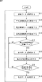
次に、図7は、EMSコントローラ25が実行する処理を説明するフローチャートである。
Next, FIG. 7 is a flowchart for explaining processing executed by the
ステップS11において、通信部31は、図1のネットワーク15を介してEMSデータベース17と通信を行って、発電電力量および需要電力量の蓄積データを取得し、電力予測部32に供給する。
In step S <b> 11, the
ステップS12において、電力予測部32は、ステップS11で通信部31から取得した発電電力量および需要電力量の蓄積データから予測発電電力量および予測需要電力量を算出し、さらに予測送受電電力量を算出する。そして、電力予測部32は、算出した予測発電電力量および予測需要電力量から、エコロジーモード、エコノミーモード、およびピークアシストモードそれぞれの目標送受電電力量を設定する。
In step S12, the
ステップS13において、ユーザが操作端末24に対する操作を行って、エコロジーモード、エコノミーモード、およびピークアシストモードそれぞれに対する割合を指定すると、電力制御モード設定部33は、その割合を取得する。
In step S <b> 13, when the user performs an operation on the
ステップS14において、目標算出部34は、ステップS13で電力制御モード設定部33が取得した割合に従って、エコロジーモード、エコノミーモード、およびピークアシストモードそれぞれの目標予測送受電電力量を加重平均し、目標予測送受電電力量を算出する。
In step S14, the
ステップS15において、電力データ取得部35は、所定の時間単位(例えば、30分)が経過したか否かを判定し、所定の時間単位が経過したと判定されるまで処理を待機する。
In step S15, the power
ステップS15において、所定の時間単位が経過したと判定されると、処理はステップS16に進み、電力データ取得部35は、その所定の時間単位で計測された電力を積算して、送受電電力量、発電電力量、および需要電力量を取得する。
If it is determined in step S15 that the predetermined time unit has elapsed, the process proceeds to step S16, and the power
ステップS17において、電力制御処理部36は、ステップS14で算出された目標予測送受電電力に沿った送受電電力となるように、電力データ取得部35が取得した送受電電力量、発電電力量、および需要電力量を参照し、電力制御システム11の電力制御を実行する。
In step S <b> 17, the power
ステップS18において、電力データ取得部35は1日分の処理が行われたか否かを判定し、1日分の処理が行われていないと判定された場合、処理はステップS15に戻り、以下、同様の処理が繰り返される。
In step S18, the power
一方、ステップS18において、1日分の処理が行われたと判定された場合、処理はステップS19に進む。電力データ取得部35は、1日分の電力データ(送受電電力量、発電電力量、および需要電力量)を、通信部31を介してEMSデータベース17に送信し、蓄積データを更新させる。そして、ステップS19の処理後、処理はステップS11に戻り、以下同様に、翌日の処理が繰り返して行われる。
On the other hand, if it is determined in step S18 that the process for one day has been performed, the process proceeds to step S19. The power
以上のように、電力制御システム11では、ユーザが、エコロジーモード、エコノミーモード、およびピークアシストモードの割合を指定し、その割合に従った目標予測送受電電力量を目標とした電力制御を時間単位で実行することができる。これにより、ユーザの要望に、より柔軟に対応した電力制御を実行することができる。例えば、ユーザの日の気分に合わせて、エコロジーモード、エコノミーモード、およびピークアシストモードそれぞれの効果(省CO2、高経済性、社会貢献)を得ることができる。
As described above, in the
また、例えば、ユーザは、翌日に電力不足が予測される場合には、ピークアシストモードの割合を高めるなど、翌日以降の動作を予約して、電力制御モードの設定を変更することができる。 In addition, for example, when power shortage is predicted on the next day, the user can change the setting of the power control mode by reserving the operation after the next day, such as increasing the ratio of the peak assist mode.
なお、例えば、電力制御システム11では、ユーザにより指定された割合で求めた目標予測送受電電力量に沿って電力制御を行った場合における、CO2排出量および売電金額などを自動的に計算して、操作端末24に表示することができる。これにより、ユーザは、CO2排出量および売電金額などを確認しながら、容易に、電力制御モードの割合を変更することができる。
For example, the
次に、図8および図9には、電力制御モード設定部33が、図1の操作端末24のタッチパネルディスプレイに表示させるユーザインタフェースの例が示されている。
Next, FIG. 8 and FIG. 9 show examples of user interfaces that the power control
例えば、電力制御システム11の電力制御モードとして、モード1、モード2、およびモード3が用意されているとき、操作端末24のタッチパネルディスプレイには、図8または図9に示すようなユーザインタフェースが表示される。図8には、レーダーチャートに類似したユーザインタフェースが示されており、図9には、棒グラフに類似したユーザインタフェースが示されている。
For example, when
ここで、モード1、モード2、およびモード3としては、上述したようなエコロジーモード、エコノミーモード、および、ピークアシストモードを用いることができる。この場合、それぞれ背反するモードであるため、例えば、電力制御モード設定部33は、時間帯ごとに相対状態を計算して、ユーザインタフェースに反映させる。
Here, as
即ち、図8および図9の上側に示すように、ユーザが、モード1の割合を増加させた場合、電力制御モード設定部33は、相対状態を計算し、図8および図9の下側に示すように、モード2およびモード3の割合を減少させる。同様に、ユーザがモード2の割合を変更した場合、電力制御モード設定部33は、モード1およびモード3の割合を計算し、ユーザがモード3の割合を変更した場合、電力制御モード設定部33は、モード1およびモード2の割合を計算して、それぞれの割合を変化させる。
That is, as shown in the upper side of FIGS. 8 and 9, when the user increases the ratio of
このように、電力制御システム11では、図8および図9に示すようなユーザインタフェースを採用することで、ユーザは、電力制御モードの割合を視覚的に確認することができ、より直観的に、電力制御システム11の電力制御モードを設定することができる。
Thus, in the
なお、ユーザが電力制御モードの割合を指定する方式としては、他にも例えば、ユーザの音声を認識することにより入力する音声入力方式や、別の端末で作成されたデータを操作端末24に転送するデータ転送方式など、様々な方式を採用することができる。
In addition, other methods for the user to specify the ratio of the power control mode include, for example, a voice input method for inputting by recognizing the user's voice, or transferring data created by another terminal to the
次に、図10には、電力制御システム11の電力制御モードの設定に利用される質問内容の例が示されている。
Next, FIG. 10 shows an example of question contents used for setting the power control mode of the
例えば、電力制御モード設定部33は、ユーザインタフェースを利用する他、図1の操作端末24のタッチパネルディスプレイに所定数の質問を表示させ、それらの質問に対する回答(YES/NO)に基づいて、電力制御システム11の電力制御モードの割合を設定することができる。
For example, in addition to using the user interface, the power control
図10には、10個の質問内容が例示されており、それぞれの質問内容に対して経済性、省CO2,ピークカットにかかる係数が設定されている。例えば、質問内容「明日は不在ですか?」に対して、経済性の係数10、省CO2の係数2、ピークカットの係数10が設定されており、質問内容「明日は休みですか?」に対して、経済性の係数5、省CO2の係数10、ピークカットの係数2が設定されている。
In FIG. 10, ten question contents are illustrated, and economic efficiency, CO2 saving, and a coefficient for peak cut are set for each question content. For example, an economic factor of 10, a CO2 saving factor of 2, and a peak cut factor of 10 are set for the question content “Is there no tomorrow?” And the question content “Is tomorrow off?” On the other hand, an
ユーザが、これらの質問内容にYESまたはNOで回答すると、電力制御モード設定部33は、YESと回答された質問内容の係数を加算し、加算した合計値の比率を、エコロジーモード、エコノミーモード、および、ピークアシストモードを加重平均する際の割合として決定する。
When the user answers YES or NO to these question contents, the power control
このように、電力制御システム11では、図10に示すような質問内容によって電力制御モードの割合を決定することで、よりユーザの気分に合わせて、電力制御システム11の電力制御モードを設定することができる。なお、質問内容は、タッチパネルディスプレイに表示する他、例えば、合成音声によってユーザに提示してもよく、ユーザの声による回答を音声認識により取得してもよい。
As described above, in the
なお、上述のフローチャートを参照して説明した各処理は、必ずしもフローチャートとして記載された順序に沿って時系列に処理する必要はなく、並列的あるいは個別に実行される処理(例えば、並列処理あるいはオブジェクトによる処理)も含むものである。また、プログラムは、1のCPUにより処理されるものであっても良いし、複数のCPUによって分散処理されるものであっても良い。 Note that the processes described with reference to the flowcharts described above do not necessarily have to be processed in chronological order in the order described in the flowcharts, but are performed in parallel or individually (for example, parallel processes or objects). Processing). The program may be processed by one CPU, or may be distributedly processed by a plurality of CPUs.
また、上述した一連の処理(情報処理方法)は、ハードウエアにより実行することもできるし、ソフトウエアにより実行することもできる。一連の処理をソフトウエアにより実行する場合には、そのソフトウエアを構成するプログラムが、専用のハードウエアに組み込まれているコンピュータ、または、各種のプログラムをインストールすることで、各種の機能を実行することが可能な、例えば汎用のパーソナルコンピュータなどに、プログラムが記録されたプログラム記録媒体からインストールされる。 Further, the above-described series of processing (information processing method) can be executed by hardware or can be executed by software. When a series of processing is executed by software, a program constituting the software executes various functions by installing a computer incorporated in dedicated hardware or various programs. For example, the program is installed in a general-purpose personal computer from a program recording medium on which the program is recorded.
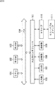
図11は、上述した一連の処理をプログラムにより実行するコンピュータのハードウエアの構成例を示すブロック図である。 FIG. 11 is a block diagram illustrating a hardware configuration example of a computer that executes the above-described series of processing by a program.
コンピュータにおいて、CPU(Central Processing Unit)101,ROM(Read Only Memory)102,RAM(Random Access Memory)103は、バス104により相互に接続されている。
In a computer, a CPU (Central Processing Unit) 101, a ROM (Read Only Memory) 102, and a RAM (Random Access Memory) 103 are connected to each other via a
バス104には、さらに、入出力インタフェース105が接続されている。入出力インタフェース105には、キーボード、マウス、マイクロホンなどよりなる入力部106、ディスプレイ、スピーカなどよりなる出力部107、ハードディスクや不揮発性のメモリなどよりなる記憶部108、ネットワークインタフェースなどよりなる通信部109、磁気ディスク、光ディスク、光磁気ディスク、或いは半導体メモリなどのリムーバブルメディア111を駆動するドライブ110が接続されている。
An input /
以上のように構成されるコンピュータでは、CPU101が、例えば、記憶部108に記憶されているプログラムを、入出力インタフェース105及びバス104を介して、RAM103にロードして実行することにより、上述した一連の処理が行われる。
In the computer configured as described above, the
コンピュータ(CPU101)が実行するプログラムは、例えば、磁気ディスク(フレキシブルディスクを含む)、光ディスク(CD-ROM(Compact Disc-Read Only Memory),DVD(Digital Versatile Disc)等)、光磁気ディスク、もしくは半導体メモリなどよりなるパッケージメディアであるリムーバブルメディア111に記録して、あるいは、ローカルエリアネットワーク、インターネット、デジタル衛星放送といった、有線または無線の伝送媒体を介して提供される。
The program executed by the computer (CPU 101) is, for example, a magnetic disk (including a flexible disk), an optical disk (CD-ROM (Compact Disc-Read Only Memory), DVD (Digital Versatile Disc), etc.), a magneto-optical disk, or a semiconductor. The program is recorded on a
そして、プログラムは、リムーバブルメディア111をドライブ110に装着することにより、入出力インタフェース105を介して、記憶部108にインストールすることができる。また、プログラムは、有線または無線の伝送媒体を介して、通信部109で受信し、記憶部108にインストールすることができる。その他、プログラムは、ROM102や記憶部108に、あらかじめインストールしておくことができる。また、本明細書において、システムとは、複数の装置により構成される装置全体を表すものである。
The program can be installed in the
なお、本実施の形態は、上述した実施の形態に限定されるものではなく、本開示の要旨を逸脱しない範囲において種々の変更が可能である。 Note that the present embodiment is not limited to the above-described embodiment, and various modifications can be made without departing from the scope of the present disclosure.
11 電力制御システム, 12 電力系統, 13 太陽光発電モジュール, 14 負荷, 15 ネットワーク, 16 上位EMS, 17 EMSデータベース, 21−1乃至21−4 電力計測部, 22 パワーコンデショナ, 23 蓄電池システム, 24 操作端末, 25 EMSコントローラ, 31 通信部, 32 電力予測部, 33 電力制御モード設定部, 34 目標算出部, 35 電力データ取得部, 36 電力制御処理部
DESCRIPTION OF
Claims (8)
複数の前記電力制御モードそれぞれにおいて目標となり日によって異なる送受電電力量から、前記割合に従って、実際に電力制御を実行する際の目標となる目標送受電電力量を算出する目標算出部と、
前記目標送受電電力量に沿って電力制御を行う電力制御処理部と
を備える電力制御装置。 A setting unit for setting a percentage by for each plurality of power control mode,
A target calculation unit that calculates a target transmission / reception power amount that is a target for actually executing power control according to the ratio from a transmission / reception power amount that is a target in each of the plurality of power control modes and varies depending on a day;
A power control apparatus comprising: a power control processing unit that performs power control along the target transmission / reception power amount.
請求項1に記載の電力制御装置。 The target calculation unit calculates the target transmission / reception power amount by performing a weighted average of a target transmission / reception power amount in each of the plurality of power control modes at the ratio set by the setting unit. The power control apparatus described.
過去の前記発電電力量および前記需要電力量の実績が蓄積された蓄積データに基づいて、前記発電部により発電されると予測される予測発電電力量、および、前記負荷による需要が発生すると予測される予測需要電力量を求める電力予測部と
をさらに備え、
前記電力予測部は、予測した前記予測発電電力量および前記予測需要電力量から予測送受電電力量を算出し、前記予測送受電電力量に従って、複数の前記電力制御モードそれぞれにおいて目標となる送受電電力量を設定する
請求項1に記載の電力制御装置。 A power measurement unit that measures generated power generated in a power generation unit that generates power using renewable energy, and demand power supplied to a load that consumes power; and
Based on the accumulated data in which the past power generation amount and the actual amount of demand power are accumulated, the predicted power generation amount predicted to be generated by the power generation unit and the demand due to the load are predicted to occur. And a power forecasting unit for obtaining a predicted demand power amount.
The power prediction unit calculates a predicted transmission / reception power amount from the predicted predicted generation power amount and the predicted demand power amount, and sets a target transmission / reception power amount in each of the plurality of power control modes according to the predicted transmission / reception power amount. The power control apparatus according to claim 1 to be set.
前記設定部は、前記操作端末が有する表示部に、複数の前記電力制御モードそれぞれに指定される割合を表示し、ユーザにより、所定の前記電力制御モードに対する前記割合の増加または減少が指定されたとき、他の前記電力制御モードに対する前記割合を変化させる
請求項1に記載の電力制御装置。 It further includes an operation terminal operated by the user,
The setting unit displays a ratio designated for each of the plurality of power control modes on a display unit included in the operation terminal, and an increase or decrease of the ratio with respect to a predetermined power control mode is designated by a user. The power control apparatus according to claim 1, wherein the ratio with respect to the other power control mode is changed.
請求項1に記載の電力制御装置。 The power control apparatus according to claim 1, wherein the setting unit presents a predetermined number of question contents set in advance to a user, and sets a ratio for a plurality of power control modes according to answers to the question contents.
複数の前記電力制御モードそれぞれにおいて目標となり日によって異なる送受電電力量から、前記割合に従って、実際に電力制御を実行する際の目標となる目標送受電電力量を算出し、
前記目標送受電電力に沿って電力制御を行う
ステップを含む電力制御方法。 Set the percentage by for each plurality of power control mode,
From the transmission / reception power amount that is a target in each of the plurality of power control modes and varies depending on the day, according to the ratio, a target transmission / reception power amount that is a target when actually executing power control is calculated,
A power control method including a step of performing power control along the target transmission / reception power.
複数の前記電力制御モードそれぞれにおいて目標となり日によって異なる送受電電力量から、前記割合に従って、実際に電力制御を実行する際の目標となる目標送受電電力量を算出し、
前記目標送受電電力に沿って電力制御を行う
ステップを含む電力制御処理をコンピュータに実行させるプログラム。 Set the percentage by for each plurality of power control mode,
From the transmission / reception power amount that is a target in each of the plurality of power control modes and varies depending on the day, according to the ratio, a target transmission / reception power amount that is a target when actually executing power control is calculated,
A program for causing a computer to execute a power control process including a step of performing power control along the target transmission / reception power.
複数の電力制御モードそれぞれに対して割合を設定する設定部と、
複数の前記電力制御モードそれぞれにおいて目標となり日によって異なる送受電電力量から、前記割合に従って、実際に電力制御を実行する際の目標となる目標送受電電力量を算出する目標算出部と、
前記目標送受電電力量に沿って電力制御を行う電力制御処理部と
を備える電力制御システム。 In a power generation system that generates power using renewable energy and a power control system to which a load that consumes power is connected,
A setting unit for setting a percentage by for each plurality of power control mode,
A target calculation unit that calculates a target transmission / reception power amount that is a target for actually executing power control according to the ratio from a transmission / reception power amount that is a target in each of the plurality of power control modes and varies depending on a day;
A power control system comprising: a power control processing unit that performs power control along the target transmission / reception power amount.
Priority Applications (2)
| Application Number | Priority Date | Filing Date | Title |
|---|---|---|---|
| JP2013052439A JP5641083B2 (en) | 2013-03-14 | 2013-03-14 | Power control apparatus, power control method, program, and power control system |
| PCT/JP2013/072003 WO2014141499A1 (en) | 2013-03-14 | 2013-08-16 | Power control device, power control method, program, and power control system |
Applications Claiming Priority (1)
| Application Number | Priority Date | Filing Date | Title |
|---|---|---|---|
| JP2013052439A JP5641083B2 (en) | 2013-03-14 | 2013-03-14 | Power control apparatus, power control method, program, and power control system |
Publications (3)
| Publication Number | Publication Date |
|---|---|
| JP2014180130A JP2014180130A (en) | 2014-09-25 |
| JP2014180130A5 JP2014180130A5 (en) | 2014-11-06 |
| JP5641083B2 true JP5641083B2 (en) | 2014-12-17 |
Family
ID=51536189
Family Applications (1)
| Application Number | Title | Priority Date | Filing Date |
|---|---|---|---|
| JP2013052439A Active JP5641083B2 (en) | 2013-03-14 | 2013-03-14 | Power control apparatus, power control method, program, and power control system |
Country Status (2)
| Country | Link |
|---|---|
| JP (1) | JP5641083B2 (en) |
| WO (1) | WO2014141499A1 (en) |
Cited By (1)
| Publication number | Priority date | Publication date | Assignee | Title |
|---|---|---|---|---|
| EP3141916A1 (en) * | 2015-09-03 | 2017-03-15 | LSIS Co., Ltd. | Power monitoring system and associated method |
Families Citing this family (11)
| Publication number | Priority date | Publication date | Assignee | Title |
|---|---|---|---|---|
| JP6189092B2 (en) * | 2013-06-03 | 2017-08-30 | 東北電力株式会社 | Multi-purpose control device for grid storage battery |
| KR101963445B1 (en) * | 2015-04-02 | 2019-07-31 | 엘에스산전 주식회사 | Power metering system and method, and system for load power monitoring |
| JP6615500B2 (en) * | 2015-06-10 | 2019-12-04 | 株式会社東芝 | Contract power determination support device, contract power determination support method, and contract power determination support program |
| KR101717849B1 (en) * | 2015-07-28 | 2017-03-17 | 엘에스산전 주식회사 | Power metering system and method, and system for load power monitoring |
| KR101717853B1 (en) | 2015-09-02 | 2017-03-27 | 엘에스산전 주식회사 | Power monitoring system and mhthod for monitoring power thereof |
| CN105186511B (en) * | 2015-10-14 | 2017-06-06 | 南京工程学院 | Battery energy storage system participates in electric grid secondary frequency modulation control method |
| CN106329568B (en) * | 2016-08-31 | 2018-10-02 | 湖北大学 | Family quotient's type photovoltaic generation economic dispatch control system |
| CN106451418B (en) * | 2016-09-13 | 2019-02-05 | 清华大学 | Photovoltaic plant divides group's equivalent modeling method online |
| JP7245625B2 (en) * | 2018-09-25 | 2023-03-24 | シャープ株式会社 | Receiving point power prediction device, receiving point power prediction method, and program |
| US11929621B2 (en) | 2019-04-26 | 2024-03-12 | Gs Yuasa International Ltd. | Power control apparatus, control method for power control apparatus, and distributed power generating system |
| US11233404B1 (en) * | 2021-01-20 | 2022-01-25 | Baidu Usa Llc | System and methods for integrating multiple photovoltaic systems |
Family Cites Families (2)
| Publication number | Priority date | Publication date | Assignee | Title |
|---|---|---|---|---|
| JP2011091985A (en) * | 2009-10-26 | 2011-05-06 | Panasonic Electric Works Co Ltd | Dc power feeding apparatus and dc power feeding system |
| JP5773768B2 (en) * | 2011-06-09 | 2015-09-02 | 大和ハウス工業株式会社 | Building power supply system and building power supply method |
-
2013
- 2013-03-14 JP JP2013052439A patent/JP5641083B2/en active Active
- 2013-08-16 WO PCT/JP2013/072003 patent/WO2014141499A1/en active Application Filing
Cited By (4)
| Publication number | Priority date | Publication date | Assignee | Title |
|---|---|---|---|---|
| EP3141916A1 (en) * | 2015-09-03 | 2017-03-15 | LSIS Co., Ltd. | Power monitoring system and associated method |
| CN106501596A (en) * | 2015-09-03 | 2017-03-15 | Ls 产电株式会社 | Power monitor system and its method for monitoring power |
| US10527658B2 (en) | 2015-09-03 | 2020-01-07 | Lsis Co., Ltd. | Power monitoring system and method for monitoring power thereof |
| CN106501596B (en) * | 2015-09-03 | 2020-04-14 | Ls 产电株式会社 | Power monitoring system and method for monitoring power thereof |
Also Published As
| Publication number | Publication date |
|---|---|
| JP2014180130A (en) | 2014-09-25 |
| WO2014141499A1 (en) | 2014-09-18 |
Similar Documents
| Publication | Publication Date | Title |
|---|---|---|
| JP5641083B2 (en) | Power control apparatus, power control method, program, and power control system | |
| Sachan et al. | Stochastic charging of electric vehicles in smart power distribution grids | |
| EP3455913B1 (en) | Systems and methods for regulating a microgrid | |
| US20160055507A1 (en) | Forecasting market prices for management of grid-scale energy storage systems | |
| JP6402550B2 (en) | Power control apparatus, power control method, program, and power control system | |
| KR20180046174A (en) | Operating System and Method for Optimal Operation of a Renewable Energy based Islanded Micro-grid | |
| KR20120112155A (en) | Systems and methods for forecasting electrical load | |
| WO2015037307A1 (en) | Power storage control device, management system, power storage control method, power storage control program, and memory medium | |
| US20160042369A1 (en) | Dynamic co-optimization management for grid scale energy storage system (gsess) market participation | |
| WO2017170018A1 (en) | Power control device, power control method, and program | |
| Fattaheian-Dehkordi et al. | Electric vehicles and electric storage systems participation in provision of flexible ramp service | |
| US20180137580A1 (en) | Power station system, and server for power station system | |
| JP6069738B2 (en) | Charge / discharge control system, charge / discharge control method, and charge / discharge control program | |
| JPWO2015019584A1 (en) | Power adjustment apparatus, power adjustment method, and program | |
| JP6394211B2 (en) | Power control apparatus, power control method, program, and power control system | |
| JP6458415B2 (en) | Power control apparatus, power control method, program, and power control system | |
| JP6237447B2 (en) | Power control apparatus, power control method, program, and power control system | |
| JP6698371B2 (en) | Electric charge management device, electric charge management method and program | |
| JP2019054647A (en) | Distributed power supply control device, distributed power supply control system, and distributed power supply control method | |
| KR102018875B1 (en) | Apparatus for managing Battery Energy Storage System and method for the same | |
| Lebedev et al. | Simulation of real time electricity price based Energy Management System | |
| JP5912055B2 (en) | Control apparatus and control method | |
| JP6626359B2 (en) | Power related information presenting apparatus, electric related information presenting method and program | |
| WO2017163934A1 (en) | Power control system, control device, control method, and computer program | |
| Kontani et al. | Integrating variable renewable energy and diverse flexibilities: Supplying carbon-free energy from a wind turbine to a data center |
Legal Events
| Date | Code | Title | Description |
|---|---|---|---|
| A521 | Request for written amendment filed |
Free format text: JAPANESE INTERMEDIATE CODE: A523 Effective date: 20140801 |
|
| A621 | Written request for application examination |
Free format text: JAPANESE INTERMEDIATE CODE: A621 Effective date: 20140801 |
|
| A871 | Explanation of circumstances concerning accelerated examination |
Free format text: JAPANESE INTERMEDIATE CODE: A871 Effective date: 20140801 |
|
| A975 | Report on accelerated examination |
Free format text: JAPANESE INTERMEDIATE CODE: A971005 Effective date: 20140819 |
|
| A131 | Notification of reasons for refusal |
Free format text: JAPANESE INTERMEDIATE CODE: A131 Effective date: 20140904 |
|
| A521 | Request for written amendment filed |
Free format text: JAPANESE INTERMEDIATE CODE: A523 Effective date: 20140911 |
|
| TRDD | Decision of grant or rejection written | ||
| A01 | Written decision to grant a patent or to grant a registration (utility model) |
Free format text: JAPANESE INTERMEDIATE CODE: A01 Effective date: 20140930 |
|
| A61 | First payment of annual fees (during grant procedure) |
Free format text: JAPANESE INTERMEDIATE CODE: A61 Effective date: 20141013 |
|
| R150 | Certificate of patent or registration of utility model |
Ref document number: 5641083 Country of ref document: JP Free format text: JAPANESE INTERMEDIATE CODE: R150 |
|
| R250 | Receipt of annual fees |
Free format text: JAPANESE INTERMEDIATE CODE: R250 |