JP3932425B2 - Heating element with less generation of magnetic field in electromagnetic wave and manufacturing method thereof - Google Patents
Heating element with less generation of magnetic field in electromagnetic wave and manufacturing method thereof Download PDFInfo
- Publication number
- JP3932425B2 JP3932425B2 JP2002230784A JP2002230784A JP3932425B2 JP 3932425 B2 JP3932425 B2 JP 3932425B2 JP 2002230784 A JP2002230784 A JP 2002230784A JP 2002230784 A JP2002230784 A JP 2002230784A JP 3932425 B2 JP3932425 B2 JP 3932425B2
- Authority
- JP
- Japan
- Prior art keywords
- heating
- heating element
- graphite
- sheet
- weight
- Prior art date
- Legal status (The legal status is an assumption and is not a legal conclusion. Google has not performed a legal analysis and makes no representation as to the accuracy of the status listed.)
- Expired - Fee Related
Links
Images

Description
【0001】
【発明の属する技術分野】
本発明は、暖房器具から発生する電磁波中の磁界の発生を低減化する電気抵抗体及びその製造方法、該電気抵抗体を備えた発熱体、並びに該発熱体を備えた暖房器具等に関する。
【0002】
【従来の技術】
発熱体として従来よりニクロム線が広く用いられているが、ニクロム線を使用する場合には、電圧及び流れる電流により電界及び磁界が発生する。この電界と磁界が相互作用して生じる電磁波は、携帯電話による医療機器の誤作動等の電磁波障害を引き起こすのみならず、人体にも悪影響をもたらす恐れがあることが指摘されている。特に、スウェーデンのカロリンスカ研究所の調査結果によれば、高圧電線の下では通常の環境下に比べて著しく白血病の発生が多いという結果が報告されており、欧米では電磁波中の磁界による生体への影響を懸念して、電気毛布等の販売数が減少しているという事実がある。そのため、電磁波中の磁界の発生が少ない器具が強く望まれている。
【0003】
しかし、ニクロム線を使う限りは電流の強さに応じて電磁波が発生し、これを低減化するためには電磁波シールド法程度しか使用されてこなかった。しかも、かかる方法では発熱体部分を金属等の導電性素材で覆うため発熱効率が低下し、かつ、低周波磁場を抑制する方法が非常に大掛かりになり、暖房器具に用いるにはほとんど不可能という欠点を有していた。
【0004】
【発明が解決しようとする課題】
従って、本発明は、従来技術の問題点を解決乃至大幅に軽減することにより、電磁波中の磁界の発生が少ない電気抵抗体及び発熱体を得る技術を提供することを主な目的とする。
【0005】
また、本発明は、2つの発熱体に位相を反転した同じ値の電流を流すことにより、電磁波中の磁界を低減化する技術を提供することをも目的とする。
【0006】
さらに、本発明は、直流電源を用いて発熱体に通電することにより電磁波中の磁界を低減化する技術を提供することをも目的とする。
【0007】
【課題を解決するための手段】
本発明者は、加硫前のゴム原料に対し、所望の電気抵抗率を得るように態様の異なる炭素材料を配合して混合した後、加硫して成形した電気抵抗体を製造し、この電気抵抗体を使用した発熱体は、同一の電力でも電磁波中の磁界の発生が少なくなることを見出した。
【0008】
また、2枚のシート状発熱体を、電流の方向性が逆になるように、すなわち位相が反転するように配置すると、更に電磁波中の磁界の発生が少なくなることも見出した。
さらに、発熱体に使用する電源を直流にすると電磁波中の磁界の発生が抑制できることもまた見出した。
【0009】
本発明者によるこのような知見は、従来技術のニッケルとクロムの合金を主体とする電気抵抗体からなる発熱体からは、到底予測し難いところである。
【0010】
すなわち、本発明は、下記の電磁波中の磁界の発生が少ない電気抵抗体及びその製造方法、該電気抵抗体を備えた発熱体、並びに該発熱体を備えた暖房器具等を提供するものである。
【0011】
項1. ゴム原料に、膨張黒鉛、カーボンブラック、並びに土壌黒鉛及び/又は鱗状黒鉛を配合して混合した後、加硫して成形することを特徴とする電気抵抗体の製造方法。
【0012】
項2. 電気抵抗率が10〜10-2 Ω・cmである電気抵抗体である項1に記載の製造方法。
【0013】
項3. ゴム原料100重量部に対し、膨張黒鉛25〜70重量部、カーボンブラック30〜80重量部、並びに土壌黒鉛10〜45重量部及び/又は鱗状黒鉛25〜100重量部を配合することを特徴とする項1又は2に記載の製造方法。
【0014】
項4. ゴム原料が、天然ゴム、イソプレンゴム、ブタジエンゴム、スチレンゴム、ブチルゴム、エチレン・プロピレンゴム、EPDM、スチレン・ブタジエンゴム、エチレン・酢ビゴム、クロロプレンゴム、ハイパロン、塩素化ポリエチレンゴム、エピクロルヒドリンゴム、ニトリルゴム、アクリルゴム、ウレタンゴム、チオコール、シリコーンゴム、及びフッ素ゴムからなる群から選ばれる少なくとも1つである項1〜3のいずれかに記載の製造方法。
【0015】
項5. 膨張黒鉛、カーボンブラック、並びに土壌黒鉛及び/又は鱗状黒鉛が、それぞれ粉末状又は繊維状であることを特徴とする項1〜4のいずれかに記載の製造方法。
【0016】
項6. 膨張黒鉛の平均粒子径が、カーボンブラックの平均粒子径、並びに土壌黒鉛及び/又は鱗状黒鉛の平均粒子径よりも大きいことを特徴とする項1〜5のいずれかに記載の製造方法。
【0017】
項7. 項1〜6のいずれかに記載の製造方法で得られる電気抵抗体。
【0018】
項8. 項7に記載の電気抵抗体及び電極からなる発熱体。
【0019】
項9. 発熱体の形状が、線状、シート状、ブロック状、らせん状、棒状、及び管状からなる群から選ばれる少なくとも1つである項8に記載の発熱体。
【0020】
項10. 項9に記載のシート状発熱体2枚の間に絶縁体を介在させてなる発熱部材及び電源からなる発熱装置であり、各シート状発熱体に流れる電流の位相が反転するように各シート状発熱体を配置したことを特徴とする発熱装置。
【0021】
項11. 電源が直流電源である項10に記載の発熱装置。
【0022】
項12. 項10又は11に記載の発熱装置及びその温度調整器を備えてなる暖房器具。
【0023】
項13. 暖房器具が寝具用暖房器具である項12に記載の暖房器具。
【0024】
【発明の実施の形態】
以下、本発明について詳細に説明する。
A.電気抵抗体
本発明の電気抵抗体の製造に用いられるゴム原料は、電気抵抗体のマトリクスとして好適に用いられる加硫前のゴム原料であればよい。該ゴム原料としては、炭素材料を含浸又は練りこむことができるものであれば特に限定はない。例えば、天然ゴム、イソプレンゴム、ブタジエンゴム、スチレンゴム、ブチルゴム、エチレン・プロピレンゴム、スチレン・ブタジエンゴム、エチレン・酢ビゴム、クロロプレンゴム、ハイパロン、塩素化ポリエチレンゴム、エピクロルヒドリンゴム、ニトリルゴム、アクリルゴム、ウレタンゴム、チオコール、シリコーンゴム、フッ素ゴム等のゴムを挙げることができる。
【0025】
これらのゴム原料は、加硫性を高めるために非共役ジエンを少量加えて共重合したものであってもよい。例えば、エチレン・プロピレンゴム・ジエンモノマー(EPDM)等が例示される。
【0026】
また、ゴム原料としては、上記に例示したゴム原料からなる群から選ばれる少なくとも1つを選択することができる。これらのゴム原料は、いずれも公知の方法によって製造することができる。
【0027】
本発明の電気抵抗体の製造に用いられる炭素材料は、膨張黒鉛、カーボンブラック、並びに土壌黒鉛及び/又は鱗状黒鉛である。
【0028】
一般に、樹脂等のマトリクスにカーボンブラック等の炭素材料を配合した発熱体は、長期間使用することにより、炭素材料の粒子がマトリクス中で移動するマイグレーション現象を引き起こしショートしやすいという問題がある。しかし、本発明者らは、マトリクス中に膨張黒鉛を配合すると、長期間の使用によっても膨張黒鉛はマイグレーション現象をほとんど起こさないことを見出した。しかも、カーボンブラック等のマイグレーションを起こしやすい他の炭素材料を膨張黒鉛と併用した場合には、マトリクスを移動してきたカーボンブラック等の炭素材料が膨張黒鉛と衝突して止まり、該炭素材料のマイグレーション現象が抑制されることをも見出した。すなわち、本発明の電気抵抗体は、この膨張黒鉛を必須成分として配合することを特徴としている。
【0029】
また、マトリクスとして用いる原料ゴムの引張り強度を大きくするために、通常カーボンブラックが配合される。
【0030】
これらの炭素材料の形状は特に限定はなく、例えば、粉末状、繊維状等いずれの形状も使用できる。炭素材料が粉末状の場合、その平均粒子径が0.1μm〜3mm程度が好ましく、繊維状の場合、その平均粒子径が50μm〜5mm程度のものが望ましい。
【0031】
さらに、本発明者らは、膨張黒鉛の平均粒子径を他の炭素材料の平均粒子径よりも大きくすると、マイグレーション現象をより抑制できることも見出した。これは、膨張黒鉛の平均粒子径が大きくなると、マイグレーション現象に対する膨張黒鉛の抵抗性が増大するためであると考えられる。例えば、膨張黒鉛の平均粒子径は5〜3000μm程度のものが使用でき、望ましくは、50〜2000μm程度、より望ましくは100〜1000μm程度のものが良い。また、カーボンブラックの平均粒子径は、市販品として0.1〜2μm程度、土壌黒鉛又は鱗状黒鉛の平均粒子径は、4〜1000μm程度が使用できる。膨張黒鉛の平均粒子径が大き過ぎると、上述したマイグレーション現象への抵抗性が高いがマトリクス中での均一分散が困難になり、逆に、平均粒子径が小さ過ぎると、均一分散が容易になるがマイグレーション現象への抵抗性が低くなる。
【0032】
なお、上記の炭素材料の平均粒子径は、顕微鏡観察や粒度分布測定装置等を用いた公知の方法を用いて測定される。
【0033】
本発明で用いられる各炭素材料の配合量は、マトリクスである原料ゴム100重量部に対し、膨張黒鉛は25〜70重量部程度(好ましくは30〜50重量部程度)、カーボンブラック30〜80重量部程度(好ましくは30〜50重量部程度)、並びに土壌黒鉛10〜45重量部程度(好ましくは20〜40重量部程度)及び/又は鱗状黒鉛25〜100重量部程度(好ましくは30〜70重量部程度)を好適に配合することができ、所望の電気抵抗率になるように適宜調製すればよい。
【0034】
本発明の電気抵抗体の電気抵抗率は、10〜10-2 Ω・cm程度であり、好ましくは10〜10-1 Ω・cm程度である。発熱体の電気抵抗率を上記範囲内とすることにより、熱拡散効率が向上し、電波吸収体として望ましい性質の1つである誘電損失が増大し、シールド効果、電磁波の乱反射等が増大することにより磁界の発生が抑制される。
【0035】
本発明の電気抵抗体は、ゴム原料に上記の炭素材料を配合して混合し、炭素材料がマトリクスであるゴム原料に均一に分散した混合物を得た後、該混合物を加硫し成形して製造される。ゴム原料と炭素材料の混合は、撹拌混合、含浸、練り込み等の公知の方法を用いることができる。得られる混合物の加硫も公知の方法を用いることができる。原料ゴム分子内に2重結合を含まないときには、過酸化物や反応性フェノール樹脂などの促進剤を用いて加硫してもよい。加硫後、電気抵抗体は、その使用目的に応じローラー成形、圧縮成形等の公知の方法を用いて成型される。例えば、線状;シート状;フィルム状;ブロック状;棒状;管状;被覆層、型物成形品等の形状等の種々の形状に成形することができる。
【0036】
本発明の電気抵抗体の発熱時における使用可能な温度範囲は、通常室温〜120℃程度、好ましくは室温〜70℃程度である。但し、ゴム原料として耐熱性のシリコーンゴム、フッ素ゴム等を用いた電気抵抗体の場合は、通常室温〜220℃程度、好ましくは室温〜150℃程度の高温まで使用可能となる。
B.発熱体
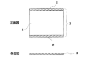
本発明の発熱体は、上記の電気抵抗体の両端に電極を備えたものである。具体的には、図1に示すような電気抵抗体1と電極2からなるシート状発熱体3を例示できる。シート状発熱体3のシート部分の厚さは、その使用目的に応じて適宜選択しうるが、例えば、電機毛布や電気カーペット等の用途であれば、通常0.5μm〜5mm程度であればよい。シート状発熱体3のシート部分の大きさ(面積)についても、使用目的に応じて適宜選択が可能である。電極2の材質としては、例えば、スティンレス、銅、金、銀、アルミニウム等の導電性金属が挙げられ、その形状としては網状、平板状、棒状、箔状等のものが挙げられる。耐久性、コスト面等から、スティンレス金網が好ましい。
【0037】
本発明の発熱体の製造方法は、本発明の効果が奏される方法であれば特に限定されない。例えば、上述の電気抵抗体を成形した後に両電極を取り付けてもよいし、電気抵抗体の成形前のゴム原料と炭素原料の混合物中に電極を埋め込んでおきその後加硫成形してもよい。
【0038】
本発明の発熱体は、同一電力を通したニクロム系発熱体に比べて約1/100程度に電磁波中の磁界を低減化できる。
C.発熱装置
また、本発明の発熱装置は、上記のシート状発熱体2枚の間に絶縁体を介在させてなる発熱部材及び電源からなり、各シート状発熱体に流れる電流の位相が反転するように各シート状発熱体を配置したものである。
【0039】
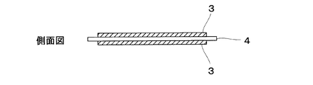
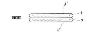
発熱部材としては、具体的には図2又は図3に示されるような層状構造からなるものが例示される。図2は、2枚のシート状発熱体3の間に、発熱体間の絶縁状態を維持できる充分な大きさのシート状絶縁体4を挟んでなる発熱部材の側面図である。図3は、2枚のシート状発熱体3を各々2つの袋状絶縁体4’に入れて絶縁し、それらを重ね合わせてなる発熱部材の側面図である。
【0040】
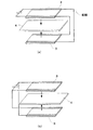
本発明の発熱装置は、上記発熱部材と電源とを導線により接続することにより製造される。具体的には図4又は図5のような構成を有する発熱装置が例示される。図4(a)又は図4(b)の発熱装置は、図2の発熱部材を構成する二つの発熱体3の配線状態を変えたものである。また、図5(a)又は図5(b)の発熱装置は、図3の発熱部材を構成する二つの発熱体3の配線状態を変えたものである。図4及び図5では、2つのシート状発熱体3の各電極が電源(ここでは直流電源を使用)に接続され、2つのシート状発熱体3に流れる電流の向きが逆になるように、すなわち電流の位相が反転するよう2つのシート状発熱体3が配置されている。図4及び図5では、電源として直流電源を用いているが、交流、直流のいずれを用いてもよい。
【0041】
絶縁体の材質としては、例えば、電気抵抗率が1012 Ω・cm程度以上のもので、耐熱性があり、容易に破壊されないものである必要がある。具体的には、シェラック、ポリエステル樹脂、ポリエチレン(PE)、エポキシ樹脂、フェノール樹脂、テフロン(登録商標)、ポリビニルクロライド(PVC)、ポリビニリデンクロライド(PVDC)等の有機高分子化合物、シリコーン、セラミックペーパー等の無機材料等が例示される。
【0042】
絶縁体の形状としては、図2の様な2枚のシート状発熱体3の間に介在させて絶縁状態を維持することができるシート状、フィルム状のものが挙げられる。その厚さは、通常1〜100μm程度であればよい。また、図3の様な各シート状発熱体3を被覆できる袋状のものであってもよい。
【0043】
上記の積層構造を有する発熱部材において、2枚のシート状発熱体3と絶縁体4又は4’の各層間は特に接着させる必要はないが、必要に応じ公知の接着性物質(例えば、エポキシ樹脂、フェノール樹脂、ポリビニルアルコール、ポリウレタン樹脂、尿素樹脂、シリコーン樹脂等の樹脂類、クロロプレン、SBR等のゴム類、その他無機系接着性物質等)を介在させてもよい。
【0044】
本発明の発熱装置によれば、通電時に2枚のシート状発熱体から生じる磁界の向きが逆になり電磁波が互いに打ち消し合うため、1枚のシート状発熱体から生じる磁界に比して約半分に減少させることができる。さらに、電源を直流にすると交流に比べ電磁波の発生をほぼ半減させることが可能となる。これは、直流電流は電磁波の発生が一方向であるため、交流電流に対し制御が容易であり、電磁波の飛散が少ないためと考えられる。
D.用途
本発明は、上記の発熱装置及び温度調整器を備えた暖房器具をも提供する。その暖房器具としては、例えば、電気ストーブ、電気こたつ、電気毛布、電気カーペット、床暖房、トイレ暖房(便座暖房等)、遠赤外線暖房器具等が挙げられる。本発明の暖房器具は、電磁波中の磁界の発生が少なく人体に対しほとんど影響を与えないため、長時間にわたり使用する可能性の高い電気毛布、電気カーペット、床暖房等の寝具用暖房器具として好適に用いられる。
【0045】
さらに、本発明は、上記の発熱装置及び温度調整器を備えた生ゴミ処理器、孵卵器、土壌暖房(温室用等)等の広範な用途にも適用可能である。
【0046】
【実施例】
以下に実施例を示し、本発明の特徴とするところをより一層明らかにするが、本発明がこれらに限定されるものではない。
【0047】
実施例1
加硫前のEPDMゴム原料100重量部に対し、粒径0.5〜2μmの粒度分布をもつカーボンブラック30重量部、16メッシュパスの膨張黒鉛粉末42重量部、及び200メッシュパスの土壌黒鉛19重量部を配合して混合した後、硫黄0.5重量部、促進剤(EM-9-80E又はS-80E、三新化学工業(株)社製)1重量部、ポリエチレングリコール0.33重量部を加えて加硫して縦27cm,横27cm,厚さ1mmに成形した。この電気抵抗体の電気抵抗率は、56Ω・cmであった。
【0048】
このゴム状電気抵抗体の横方向の端に幅1.0cm、厚み0.1mm、のスティンレス金網を埋め込み電極とした。このときの見掛けの電気抵抗値は、88Ωであった。
【0049】
電極間に交流100Vの電圧をかけ、温度調整器にて表面温度を40℃にしたときの表面部分の磁界は、1.0mGであった。
【0050】
なお、磁界は磁気シールドルーム内において、交流及び直流のいずれも測定可能なトリフィールドメーターを用いて測定した。
【0051】
実施例2
加硫前のEPDMゴム原料100重量部に対し、粒径0.5〜2μmの粒度分布をもつカーボンブラック30重量部、16メッシュパスの膨張黒鉛粉末57重量部、及び200メッシュパスの鱗状黒鉛29重量部を配合する他は、実施例1と同様にして発熱体を作製した。電極間に交流24Vの電圧をかけ、表面温度を40℃にしたときの表面部分の磁界は、0.251mGであった。
【0052】
評価は実施例1と同様にして行った。
【0053】
実施例3
加硫前のEPDMゴム原料100重量部に対し、粒径0.5〜2μmの粒度分布をもつカーボンブラック30重量部、16メッシュの膨張黒鉛粉末83重量部、及び200メッシュの鱗状黒鉛43重量部を配合する他は、実施例1と同様にして発熱体を作製した。電極間に交流12Vの電圧をかけ、表面温度を40℃にしたときの磁界は、0.13mGであった。
【0054】
評価は実施例1と同様にして行った。
【0055】
実施例4
実施例1に記載の発熱体2枚の間にポリエステルフィルム(厚さ:約10〜50μm)を介在させ、2枚の発熱体に流れる電流の位相を反転させるように配置した。それぞれの発熱体に100Vとなるように並列に結線して、磁界を実施例1と同様に測定したところ、0.5mGであった。
【0056】
実施例5
電源に直流100Vを用いる以外は、実施例1と同様に行ったところ、磁界は、0.5mGであった。
【0057】
比較例1
市販のニクロム線(BS-T32型(可変式)、電子回路敷毛布「長さん」サンヨー電気(株)社製)からなる電気毛布に100Vの電圧時における実施例1と同一電力となるよう通電したときの発熱体の表面における磁界は、100mG以上であった。
【0058】
比較例2
電圧を交流24Vとする他は、比較例1と同様に行ったところ、発熱体の表面における磁界は、53mGであった。
【0059】
比較例3
電圧を交流12Vとする他は、比較例1と同様に行った発熱体の表面における磁界は、27mGであった。
【0060】
【発明の効果】
本発明の電気抵抗体は、ゴム原料に膨張黒鉛等の炭素材料を配合し加硫成形したものである。この電気抵抗体は、従来のニクロム発熱体に比べて通電時に発生する電磁波中の磁界強度が1/100以下に低減化される。これは、膨張黒鉛を配合することによる誘電損失の増大(電波吸収体として望ましい性質の1つである)、シールド効果、電磁波の乱反射等により磁界の発生が低減されたためと考えられる。
【0061】
上記電気抵抗体と電極からなる本発明の発熱体2枚を、位相が反転するようにして配置した本発明の発熱装置においては、全体として2倍電力を消費するにもかかわらず、磁界強度が発熱体1枚の時より半減する。
【0062】
本発明の発熱装置に直流電源を用いた場合、交流電源を用いた場合より発生する磁界強度が半減する。
【0063】
線状の発熱体であるニクロム線は局部加熱方式を採用せざるを得ないため温度むらが生じ、使用に際しその上に絶縁体及びアルミ板等を敷いて温度の均一化を図る必要がある。一方で、本発明の発熱体はその形状を任意に成形することができ、例えば、シート状の形状に成形すれば温度むらなくシート全体を均一な温度で発熱させることができる。
【0064】
また、ニクロム線は局部加熱方式であるため温度むらが生じ、ニクロム線上は設定温度よりも高くなるため局部過熱により発火の危険性があるが、本発明の発熱体は、発熱体全体で均一な温度で発熱するため温度むらがなく安全性の点からも好ましい。
【0065】
本発明の発熱体は、通電時電磁波中の磁界強度が小さく人体、動物への影響がほとんどないと考えられるため、広く暖房器具、孵卵器、生ゴミ処理機等の発熱体として用いることができる。特に、寝具用暖房器具として好適に用いることができる。
【図面の簡単な説明】
【図1】本発明の発熱体の一例を示す図である。
【図2】本発明の発熱部材の一例を示す図である。
【図3】本発明の発熱部材の一例を示す図である。
【図4】図2の発熱部材及び電源からなる発熱装置の構成を示す図である。
【図5】図3の発熱部材及び電源からな発熱装置の構成を示す図である。
【符号の説明】
1 電気抵抗体
2 電極
3 シート状発熱体
4 シート状絶縁体
4’袋状絶縁体[0001]
BACKGROUND OF THE INVENTION
The present invention relates to an electric resistor that reduces the generation of a magnetic field in electromagnetic waves generated from a heating appliance, a method for manufacturing the same, a heating element including the electric resistor, a heating appliance including the heating element, and the like.
[0002]
[Prior art]
Conventionally, nichrome wire has been widely used as a heating element, but when a nichrome wire is used, an electric field and a magnetic field are generated by voltage and flowing current. It has been pointed out that the electromagnetic wave generated by the interaction between the electric field and the magnetic field not only causes an electromagnetic interference such as a malfunction of a medical device by a mobile phone, but may also have an adverse effect on the human body. In particular, according to the results of a survey by the Karolinska Institute in Sweden, it has been reported that leukemia is significantly more common under high-voltage power lines than in normal environments. There is a fact that sales of electric blankets etc. are decreasing due to concern about the impact. Therefore, an instrument that generates less magnetic field in electromagnetic waves is strongly desired.
[0003]
However, as long as nichrome wire is used, electromagnetic waves are generated according to the strength of the current, and only the electromagnetic shielding method has been used to reduce this. In addition, in such a method, the heating element portion is covered with a conductive material such as metal, so that the heat generation efficiency is reduced, and the method of suppressing the low frequency magnetic field is very large and almost impossible to use for heating appliances. Had drawbacks.
[0004]
[Problems to be solved by the invention]
Accordingly, it is a main object of the present invention to provide a technique for obtaining an electric resistor and a heating element that generate less magnetic field in electromagnetic waves by solving or greatly reducing the problems of the prior art.
[0005]
Another object of the present invention is to provide a technique for reducing a magnetic field in an electromagnetic wave by flowing currents having the same value with reversed phases to two heating elements.
[0006]
Another object of the present invention is to provide a technique for reducing a magnetic field in an electromagnetic wave by energizing a heating element using a DC power source.
[0007]
[Means for Solving the Problems]
The inventor manufactures an electric resistor formed by vulcanization and molding after blending and mixing carbon materials having different modes with a rubber raw material before vulcanization so as to obtain a desired electric resistivity. It has been found that a heating element using an electrical resistor generates less magnetic field in electromagnetic waves even with the same power.
[0008]
It has also been found that when two sheet-like heating elements are arranged so that the direction of current is reversed, that is, the phase is reversed, the generation of a magnetic field in electromagnetic waves is further reduced.
Furthermore, it has also been found that the generation of a magnetic field in electromagnetic waves can be suppressed when the power source used for the heating element is a direct current.
[0009]
Such knowledge by the present inventor is hard to predict from a heating element made of an electric resistor mainly composed of an alloy of nickel and chromium according to the prior art.
[0010]
That is, the present invention provides an electrical resistor with less generation of a magnetic field in the following electromagnetic wave, a method for producing the same, a heating element including the electrical resistor, a heating appliance including the heating element, and the like. .
[0011]
[0012]
[0013]
[0014]
[0015]
Item 5. Item 5. The production method according to any one of
[0016]
Item 6. Item 6. The production method according to any one of
[0017]
Item 7. Item 7. An electrical resistor obtained by the production method according to any one of
[0018]
Item 8. Item 8. A heating element comprising the electrical resistor and the electrode according to Item 7.
[0019]
Item 9. Item 9. The heating element according to Item 8, wherein the shape of the heating element is at least one selected from the group consisting of a linear shape, a sheet shape, a block shape, a spiral shape, a rod shape, and a tubular shape.
[0020]
Item 10. Item 10. A heating device comprising a heating member and a power source with an insulator interposed between two sheet-like heating elements according to Item 9, wherein each sheet-like shape is reversed so that the phase of the current flowing through each sheet-like heating element is reversed. A heating device characterized by arranging a heating element.
[0021]
Item 11. Item 11. The heating device according to Item 10, wherein the power source is a DC power source.
[0022]
Item 12. Item 12. A heating appliance comprising the heating device according to Item 10 or 11 and a temperature regulator thereof.
[0023]
Item 13. Item 13. The heating device according to Item 12, wherein the heating device is a bedding heating device.
[0024]
DETAILED DESCRIPTION OF THE INVENTION
Hereinafter, the present invention will be described in detail.
A. Electric resistor The rubber raw material used in the production of the electric resistor of the present invention may be a rubber raw material before vulcanization that is preferably used as a matrix of the electric resistor. The rubber material is not particularly limited as long as it can be impregnated or kneaded with a carbon material. For example, natural rubber, isoprene rubber, butadiene rubber, styrene rubber, butyl rubber, ethylene / propylene rubber, styrene / butadiene rubber, ethylene / vinyl acetate rubber, chloroprene rubber, hyperon, chlorinated polyethylene rubber, epichlorohydrin rubber, nitrile rubber, acrylic rubber, Mention may be made of rubbers such as urethane rubber, thiocol, silicone rubber and fluorine rubber.
[0025]
These rubber materials may be copolymerized by adding a small amount of non-conjugated diene in order to improve vulcanizability. Examples thereof include ethylene / propylene rubber / diene monomer (EPDM).
[0026]
Moreover, as a rubber raw material, at least 1 chosen from the group which consists of the rubber raw material illustrated above can be selected. Any of these rubber raw materials can be produced by a known method.
[0027]
The carbon material used for manufacturing the electric resistor of the present invention is expanded graphite, carbon black, and soil graphite and / or scaly graphite.
[0028]
In general, a heating element in which a carbon material such as carbon black is blended in a matrix such as a resin has a problem that, when used for a long period of time, a migration phenomenon in which particles of the carbon material move in the matrix is caused and short-circuiting easily occurs. However, the present inventors have found that when expanded graphite is blended in a matrix, expanded graphite hardly causes a migration phenomenon even after long-term use. In addition, when other carbon materials such as carbon black that are prone to migration are used together with expanded graphite, the carbon material such as carbon black that has moved through the matrix stops colliding with the expanded graphite, and the migration phenomenon of the carbon material Has also been found to be suppressed. That is, the electrical resistor of the present invention is characterized by blending this expanded graphite as an essential component.
[0029]
Carbon black is usually blended in order to increase the tensile strength of the raw rubber used as the matrix.
[0030]
The shape of these carbon materials is not particularly limited, and for example, any shape such as powder or fiber can be used. When the carbon material is in powder form, the average particle diameter is preferably about 0.1 μm to 3 mm, and when the carbon material is fibrous, the average particle diameter is preferably about 50 μm to 5 mm.
[0031]
Furthermore, the present inventors have also found that the migration phenomenon can be further suppressed by making the average particle diameter of expanded graphite larger than the average particle diameter of other carbon materials. This is considered to be because the expanded graphite's resistance to the migration phenomenon increases as the average particle size of the expanded graphite increases. For example, an expanded graphite having an average particle size of about 5 to 3000 μm can be used, preferably about 50 to 2000 μm, more preferably about 100 to 1000 μm. Moreover, the average particle diameter of carbon black can be about 0.1 to 2 μm as a commercial product, and the average particle diameter of soil graphite or scaly graphite can be about 4 to 1000 μm. If the average particle size of the expanded graphite is too large, the resistance to the migration phenomenon described above is high, but uniform dispersion in the matrix becomes difficult. Conversely, if the average particle size is too small, uniform dispersion becomes easy. However, the resistance to the migration phenomenon is lowered.
[0032]
In addition, the average particle diameter of said carbon material is measured using the well-known method using microscope observation, a particle size distribution measuring apparatus, etc.
[0033]
The compounding amount of each carbon material used in the present invention is about 25 to 70 parts by weight (preferably about 30 to 50 parts by weight) of expanded graphite and 30 to 80 parts by weight of carbon black with respect to 100 parts by weight of raw rubber as a matrix. Part (preferably about 30 to 50 parts by weight), soil graphite about 10 to 45 parts by weight (preferably about 20 to 40 parts by weight) and / or scale-like graphite about 25 to 100 parts by weight (preferably 30 to 70 parts by weight) About a part) can be suitably blended, and it may be appropriately prepared so as to have a desired electrical resistivity.
[0034]
The electrical resistivity of the electrical resistor of the present invention is about 10 to 10 −2 Ω · cm, and preferably about 10 to 10 −1 Ω · cm. By making the electric resistivity of the heating element within the above range, the thermal diffusion efficiency is improved, the dielectric loss which is one of desirable properties as a radio wave absorber is increased, and the shielding effect, the electromagnetic wave irregular reflection, etc. are increased. This suppresses the generation of a magnetic field.
[0035]
The electrical resistor of the present invention is obtained by mixing and mixing the above carbon material with a rubber raw material to obtain a mixture in which the carbon material is uniformly dispersed in the rubber raw material as a matrix, and then vulcanizing and molding the mixture. Manufactured. For mixing the rubber raw material and the carbon material, known methods such as stirring and mixing, impregnation and kneading can be used. Known methods can also be used for vulcanization of the resulting mixture. When the raw rubber molecule does not contain a double bond, it may be vulcanized using an accelerator such as a peroxide or a reactive phenol resin. After vulcanization, the electrical resistor is molded using a known method such as roller molding or compression molding according to the purpose of use. For example, it can be formed into various shapes such as a linear shape, a sheet shape, a film shape, a block shape, a rod shape, a tubular shape, a shape of a coating layer, a molded article, and the like.
[0036]
The usable temperature range of the electric resistor of the present invention during heat generation is usually about room temperature to 120 ° C, preferably about room temperature to 70 ° C. However, in the case of an electrical resistor using heat-resistant silicone rubber, fluororubber or the like as a rubber raw material, it can be used usually at a room temperature to about 220 ° C., preferably a room temperature to about 150 ° C.
B. Heating element The heating element of the present invention is provided with electrodes on both ends of the electric resistor. Specifically, a sheet-
[0037]
The method for producing the heating element of the present invention is not particularly limited as long as the effect of the present invention is achieved. For example, both electrodes may be attached after the above-described electric resistor is molded, or the electrode may be embedded in a mixture of a rubber raw material and a carbon raw material before forming the electric resistor and then vulcanized.
[0038]
The heating element of the present invention can reduce the magnetic field in electromagnetic waves to about 1/100 compared to a nichrome heating element that passes the same power.
C. Heat generating device The heat generating device of the present invention includes a heat generating member and a power source in which an insulator is interposed between the two sheet-shaped heat generating elements, and a phase of a current flowing through each sheet-shaped heat generating element. Each sheet-like heating element is disposed so as to be reversed.
[0039]
Specific examples of the heat generating member include those having a layered structure as shown in FIG. 2 or FIG. FIG. 2 is a side view of a heat generating member in which a sheet-shaped
[0040]
The heat generating device of the present invention is manufactured by connecting the heat generating member and a power source with a conducting wire. Specifically, a heat generating device having a configuration as shown in FIG. 4 or 5 is exemplified. 4 (a) or 4 (b) is obtained by changing the wiring state of the two
[0041]
As the material of the insulator, for example, it is necessary that it has an electric resistivity of about 10 12 Ω · cm or more, has heat resistance, and cannot be easily broken. Specifically, organic polymer compounds such as shellac, polyester resin, polyethylene (PE), epoxy resin, phenol resin, Teflon (registered trademark), polyvinyl chloride (PVC), polyvinylidene chloride (PVDC), silicone, ceramic paper Examples thereof include inorganic materials.
[0042]
Examples of the shape of the insulator include a sheet and a film that can be maintained between two sheet-
[0043]
In the heat generating member having the above-described laminated structure, it is not necessary to particularly bond the respective layers of the two sheet-like
[0044]
According to the heat generating device of the present invention, the directions of the magnetic fields generated from the two sheet-shaped heating elements are reversed when energized, and the electromagnetic waves cancel each other. Can be reduced. Furthermore, when the power source is a direct current, the generation of electromagnetic waves can be reduced by half compared to the alternating current. This is thought to be because direct current is generated in one direction, and direct current is easy to control with respect to alternating current, and there is little scattering of electromagnetic waves.
D. Use The present invention also provides a heating appliance provided with the heat generating device and the temperature regulator. Examples of the heater include an electric heater, electric kotatsu, electric blanket, electric carpet, floor heating, toilet heating (toilet seat heating, etc.), far-infrared heater, and the like. The heating appliance of the present invention is suitable as a heating appliance for bedding such as an electric blanket, an electric carpet, and a floor heating that has a high possibility of being used for a long time because it hardly generates a magnetic field in electromagnetic waves and hardly affects the human body. Used for.
[0045]
Furthermore, the present invention can also be applied to a wide range of uses such as a garbage disposal device, an incubator, and soil heating (for a greenhouse, etc.) provided with the heat generating device and the temperature controller.
[0046]
【Example】
EXAMPLES Examples will be shown below to further clarify the features of the present invention, but the present invention is not limited to these.
[0047]
Example 1
30 parts by weight of carbon black having a particle size distribution of 0.5 to 2 μm, 42 parts by weight of expanded graphite powder of 16 mesh pass, and 19 parts by weight of soil graphite of 200 mesh pass with respect to 100 parts by weight of the raw material of EPDM rubber before vulcanization After mixing and mixing, 0.5 parts by weight of sulfur, 1 part by weight of accelerator (EM-9-80E or S-80E, manufactured by Sanshin Chemical Industry Co., Ltd.) and 0.33 parts by weight of polyethylene glycol are added to vulcanize. Then, it was formed into a length of 27 cm, a width of 27 cm and a thickness of 1 mm. The electrical resistivity of this electrical resistor was 56 Ω · cm.
[0048]
A stainless steel mesh having a width of 1.0 cm and a thickness of 0.1 mm was used as a buried electrode at the lateral end of the rubber-like electric resistor. The apparent electrical resistance value at this time was 88Ω.
[0049]
When a voltage of AC 100V was applied between the electrodes and the surface temperature was adjusted to 40 ° C. with a temperature controller, the magnetic field at the surface portion was 1.0 mG.
[0050]
The magnetic field was measured in a magnetic shield room using a trifield meter capable of measuring both alternating current and direct current.
[0051]
Example 2
30 parts by weight of carbon black having a particle size distribution of 0.5 to 2 μm, 57 parts by weight of expanded graphite powder of 16 mesh pass, and 29 parts by weight of scaly graphite of 200 mesh pass with respect to 100 parts by weight of EPDM rubber raw material before vulcanization A heating element was produced in the same manner as in Example 1 except for blending. When a voltage of 24V AC was applied between the electrodes and the surface temperature was 40 ° C., the magnetic field at the surface portion was 0.251 mG.
[0052]
Evaluation was performed in the same manner as in Example 1.
[0053]
Example 3
30 parts by weight of carbon black having a particle size distribution of 0.5-2 μm, 83 parts by weight of 16-mesh expanded graphite powder, and 43 parts by weight of 200-mesh scale graphite are blended with 100 parts by weight of EPDM rubber raw material before vulcanization. Except for this, a heating element was produced in the same manner as in Example 1. The magnetic field was 0.13 mG when an AC voltage of 12 V was applied between the electrodes and the surface temperature was 40 ° C.
[0054]
Evaluation was performed in the same manner as in Example 1.
[0055]
Example 4
A polyester film (thickness: about 10 to 50 μm) was interposed between the two heating elements described in Example 1 so as to reverse the phase of the current flowing through the two heating elements. Each of the heating elements was connected in parallel so as to be 100 V, and the magnetic field was measured in the same manner as in Example 1. As a result, it was 0.5 mG.
[0056]
Example 5
A magnetic field of 0.5 mG was obtained in the same manner as in Example 1 except that DC 100 V was used for the power source.
[0057]
Comparative Example 1
An electric blanket made of a commercially available nichrome wire (BS-T32 type (variable), electronic circuit blanket “Nagasan” manufactured by Sanyo Electric Co., Ltd.)) is energized to have the same power as in Example 1 at a voltage of 100V. The magnetic field on the surface of the heating element was 100 mG or more.
[0058]
Comparative Example 2
The magnetic field on the surface of the heating element was 53 mG when the same procedure as in Comparative Example 1 was performed except that the voltage was 24 V AC.
[0059]
Comparative Example 3
The magnetic field on the surface of the heating element, which was performed in the same manner as in Comparative Example 1, except that the voltage was 12 V AC, was 27 mG.
[0060]
【The invention's effect】
The electrical resistor of the present invention is obtained by blending a rubber material with a carbon material such as expanded graphite and vulcanizing and molding it. This electric resistor has a magnetic field intensity in an electromagnetic wave generated during energization reduced to 1/100 or less as compared with a conventional nichrome heating element. This is presumably because the generation of a magnetic field was reduced by the increase in dielectric loss (which is one of desirable properties as a radio wave absorber), the shielding effect, the irregular reflection of electromagnetic waves, and the like by adding expanded graphite.
[0061]
In the heating device of the present invention in which the two heating elements of the present invention comprising the electric resistor and the electrode are arranged so that the phase is reversed, the magnetic field strength is low even though the power consumption is twice as a whole. It is halved from the case of one heating element.
[0062]
When a DC power source is used for the heat generating device of the present invention, the magnetic field strength generated by using an AC power source is halved.
[0063]
Nichrome wire, which is a linear heating element, has to adopt a local heating method, resulting in uneven temperature. In use, it is necessary to lay an insulator, an aluminum plate, etc. on it to make the temperature uniform. On the other hand, the shape of the heating element of the present invention can be arbitrarily formed. For example, if it is formed into a sheet-like shape, the entire sheet can be heated at a uniform temperature without temperature unevenness.
[0064]
Nichrome wire is a local heating method, resulting in temperature unevenness, and the nichrome wire is higher than the set temperature, so there is a risk of ignition due to local overheating, but the heating element of the present invention is uniform throughout the heating element. Since heat is generated at temperature, there is no temperature unevenness, which is preferable from the viewpoint of safety.
[0065]
Since the heating element of the present invention is considered to have a small magnetic field intensity in electromagnetic waves when energized and hardly affects humans and animals, it can be widely used as a heating element for heating appliances, incubators, garbage processing machines, etc. . In particular, it can be suitably used as a heating device for bedding.
[Brief description of the drawings]
FIG. 1 is a diagram showing an example of a heating element of the present invention.
FIG. 2 is a view showing an example of a heat generating member of the present invention.
FIG. 3 is a view showing an example of a heat generating member of the present invention.
4 is a diagram showing a configuration of a heat generating device including a heat generating member and a power source in FIG. 2;
5 is a diagram illustrating a configuration of a heat generating device including a heat generating member and a power source in FIG. 3;
[Explanation of symbols]
DESCRIPTION OF
Claims (13)
Priority Applications (1)
| Application Number | Priority Date | Filing Date | Title |
|---|---|---|---|
| JP2002230784A JP3932425B2 (en) | 2002-08-08 | 2002-08-08 | Heating element with less generation of magnetic field in electromagnetic wave and manufacturing method thereof |
Applications Claiming Priority (1)
| Application Number | Priority Date | Filing Date | Title |
|---|---|---|---|
| JP2002230784A JP3932425B2 (en) | 2002-08-08 | 2002-08-08 | Heating element with less generation of magnetic field in electromagnetic wave and manufacturing method thereof |
Publications (2)
| Publication Number | Publication Date |
|---|---|
| JP2004071424A JP2004071424A (en) | 2004-03-04 |
| JP3932425B2 true JP3932425B2 (en) | 2007-06-20 |
Family
ID=32016738
Family Applications (1)
| Application Number | Title | Priority Date | Filing Date |
|---|---|---|---|
| JP2002230784A Expired - Fee Related JP3932425B2 (en) | 2002-08-08 | 2002-08-08 | Heating element with less generation of magnetic field in electromagnetic wave and manufacturing method thereof |
Country Status (1)
| Country | Link |
|---|---|
| JP (1) | JP3932425B2 (en) |
Cited By (1)
| Publication number | Priority date | Publication date | Assignee | Title |
|---|---|---|---|---|
| CN102798169A (en) * | 2012-07-26 | 2012-11-28 | 金银 | Non-electromagnetic-wave heating composite floor |
Families Citing this family (8)
| Publication number | Priority date | Publication date | Assignee | Title |
|---|---|---|---|---|
| CN100575407C (en) * | 2007-06-18 | 2009-12-30 | 刘明荣 | Product of scale graphite and manufacture method thereof |
| CN101945508B (en) * | 2010-09-20 | 2012-04-18 | 肖仲强 | Low-electromagnetic wave electric heating panel |
| JP5639864B2 (en) * | 2010-11-30 | 2014-12-10 | 株式会社アステア | Direct current heating method |
| JP2013030513A (en) * | 2011-07-26 | 2013-02-07 | Seiko Epson Corp | Gas cell unit and atomic oscillator |
| WO2017136806A1 (en) | 2016-02-04 | 2017-08-10 | General Nano Llc | Carbon nanotube sheet structure and method for its making |
| JP6843738B2 (en) | 2014-07-30 | 2021-03-17 | ジェネラル ナノ エルエルシー | Carbon nanotube sheet structure and its manufacturing method |
| CN108282911A (en) * | 2018-01-23 | 2018-07-13 | 深圳力士智造科技有限公司 | The even temperature heating board of one kind and production method |
| CN115787919A (en) * | 2021-06-09 | 2023-03-14 | 重庆大学 | Phase-change material particle applied to phase-change heat storage plate for building |
-
2002
- 2002-08-08 JP JP2002230784A patent/JP3932425B2/en not_active Expired - Fee Related
Cited By (1)
| Publication number | Priority date | Publication date | Assignee | Title |
|---|---|---|---|---|
| CN102798169A (en) * | 2012-07-26 | 2012-11-28 | 金银 | Non-electromagnetic-wave heating composite floor |
Also Published As
| Publication number | Publication date |
|---|---|
| JP2004071424A (en) | 2004-03-04 |
Similar Documents
| Publication | Publication Date | Title |
|---|---|---|
| JP3932425B2 (en) | Heating element with less generation of magnetic field in electromagnetic wave and manufacturing method thereof | |
| CA1147787A (en) | Heated floor mat | |
| CN102083246B (en) | Far-infrared electric heating film | |
| EP2400814A2 (en) | Carbon nanotube sheet heater | |
| US20040188418A1 (en) | Low cost heating devices manufactured from conductive loaded resin-based materials | |
| KR20020005166A (en) | Carbonite fiber heating Paper and board | |
| US7196288B2 (en) | Flexible heating element | |
| KR101813685B1 (en) | Manufacturing Method of Sheet Type Heating Element | |
| US10827566B2 (en) | Susceptor wire array | |
| WO2016017765A1 (en) | Elastomer heater | |
| EP3654736B1 (en) | Hybrid nanoreinforced liner for microwave oven | |
| CN216217599U (en) | Amorphous alloy heating assembly and heating equipment | |
| US20230043071A1 (en) | Electrode Assembly for Applying Tumor Treating Fields (TTFields) that Include a Sheet of Graphite | |
| JP2008198407A (en) | Sheet heater | |
| US3238355A (en) | Particle filled conductor | |
| EP1467598A2 (en) | Low cost heating devices manufactured from conductive resin-based materials | |
| JP3882622B2 (en) | PTC resistor | |
| IL48165A (en) | Flexible electric area heating elements and their manufacture | |
| JP2004055219A (en) | Seat heater | |
| KR101813134B1 (en) | Thermally variable conductive carbon ink coating liquid and conductive plane film using the same | |
| KR20190016533A (en) | Composite material heating element containing Carbon nanotube and the method thereof | |
| US3595720A (en) | Heating elements | |
| JP7265238B2 (en) | Flexible sheet heating element | |
| JPH01213978A (en) | Surface-shaped heat emitting body | |
| DE102020100226A1 (en) | Electric heating mat |
Legal Events
| Date | Code | Title | Description |
|---|---|---|---|
| A621 | Written request for application examination |
Free format text: JAPANESE INTERMEDIATE CODE: A621 Effective date: 20040610 |
|
| A977 | Report on retrieval |
Free format text: JAPANESE INTERMEDIATE CODE: A971007 Effective date: 20060911 |
|
| A131 | Notification of reasons for refusal |
Free format text: JAPANESE INTERMEDIATE CODE: A131 Effective date: 20061115 |
|
| A521 | Written amendment |
Free format text: JAPANESE INTERMEDIATE CODE: A523 Effective date: 20070112 |
|
| TRDD | Decision of grant or rejection written | ||
| A01 | Written decision to grant a patent or to grant a registration (utility model) |
Free format text: JAPANESE INTERMEDIATE CODE: A01 Effective date: 20070221 |
|
| A61 | First payment of annual fees (during grant procedure) |
Free format text: JAPANESE INTERMEDIATE CODE: A61 Effective date: 20070302 |
|
| R150 | Certificate of patent or registration of utility model |
Free format text: JAPANESE INTERMEDIATE CODE: R150 |
|
| FPAY | Renewal fee payment (event date is renewal date of database) |
Free format text: PAYMENT UNTIL: 20100330 Year of fee payment: 3 |
|
| FPAY | Renewal fee payment (event date is renewal date of database) |
Free format text: PAYMENT UNTIL: 20110330 Year of fee payment: 4 |
|
| LAPS | Cancellation because of no payment of annual fees |