JP3772096B2 - Power conditioner for photovoltaic system - Google Patents
Power conditioner for photovoltaic system Download PDFInfo
- Publication number
- JP3772096B2 JP3772096B2 JP2001114966A JP2001114966A JP3772096B2 JP 3772096 B2 JP3772096 B2 JP 3772096B2 JP 2001114966 A JP2001114966 A JP 2001114966A JP 2001114966 A JP2001114966 A JP 2001114966A JP 3772096 B2 JP3772096 B2 JP 3772096B2
- Authority
- JP
- Japan
- Prior art keywords
- power
- inverter
- remote controller
- data
- power supply
- Prior art date
- Legal status (The legal status is an assumption and is not a legal conclusion. Google has not performed a legal analysis and makes no representation as to the accuracy of the status listed.)
- Expired - Fee Related
Links
Images


Classifications
-
- H—ELECTRICITY
- H02—GENERATION; CONVERSION OR DISTRIBUTION OF ELECTRIC POWER
- H02M—APPARATUS FOR CONVERSION BETWEEN AC AND AC, BETWEEN AC AND DC, OR BETWEEN DC AND DC, AND FOR USE WITH MAINS OR SIMILAR POWER SUPPLY SYSTEMS; CONVERSION OF DC OR AC INPUT POWER INTO SURGE OUTPUT POWER; CONTROL OR REGULATION THEREOF
- H02M5/00—Conversion of ac power input into ac power output, e.g. for change of voltage, for change of frequency, for change of number of phases
- H02M5/40—Conversion of ac power input into ac power output, e.g. for change of voltage, for change of frequency, for change of number of phases with intermediate conversion into dc
- H02M5/42—Conversion of ac power input into ac power output, e.g. for change of voltage, for change of frequency, for change of number of phases with intermediate conversion into dc by static converters
- H02M5/44—Conversion of ac power input into ac power output, e.g. for change of voltage, for change of frequency, for change of number of phases with intermediate conversion into dc by static converters using discharge tubes or semiconductor devices to convert the intermediate dc into ac
- H02M5/443—Conversion of ac power input into ac power output, e.g. for change of voltage, for change of frequency, for change of number of phases with intermediate conversion into dc by static converters using discharge tubes or semiconductor devices to convert the intermediate dc into ac using devices of a thyratron or thyristor type requiring extinguishing means
- H02M5/45—Conversion of ac power input into ac power output, e.g. for change of voltage, for change of frequency, for change of number of phases with intermediate conversion into dc by static converters using discharge tubes or semiconductor devices to convert the intermediate dc into ac using devices of a thyratron or thyristor type requiring extinguishing means using semiconductor devices only
-
- H—ELECTRICITY
- H02—GENERATION; CONVERSION OR DISTRIBUTION OF ELECTRIC POWER
- H02J—CIRCUIT ARRANGEMENTS OR SYSTEMS FOR SUPPLYING OR DISTRIBUTING ELECTRIC POWER; SYSTEMS FOR STORING ELECTRIC ENERGY
- H02J3/00—Circuit arrangements for ac mains or ac distribution networks
- H02J3/38—Arrangements for parallely feeding a single network by two or more generators, converters or transformers
- H02J3/381—Dispersed generators
-
- H—ELECTRICITY
- H02—GENERATION; CONVERSION OR DISTRIBUTION OF ELECTRIC POWER
- H02M—APPARATUS FOR CONVERSION BETWEEN AC AND AC, BETWEEN AC AND DC, OR BETWEEN DC AND DC, AND FOR USE WITH MAINS OR SIMILAR POWER SUPPLY SYSTEMS; CONVERSION OF DC OR AC INPUT POWER INTO SURGE OUTPUT POWER; CONTROL OR REGULATION THEREOF
- H02M7/00—Conversion of ac power input into dc power output; Conversion of dc power input into ac power output
- H02M7/42—Conversion of dc power input into ac power output without possibility of reversal
- H02M7/44—Conversion of dc power input into ac power output without possibility of reversal by static converters
- H02M7/48—Conversion of dc power input into ac power output without possibility of reversal by static converters using discharge tubes with control electrode or semiconductor devices with control electrode
- H02M7/4807—Conversion of dc power input into ac power output without possibility of reversal by static converters using discharge tubes with control electrode or semiconductor devices with control electrode having a high frequency intermediate AC stage
-
- H—ELECTRICITY
- H02—GENERATION; CONVERSION OR DISTRIBUTION OF ELECTRIC POWER
- H02J—CIRCUIT ARRANGEMENTS OR SYSTEMS FOR SUPPLYING OR DISTRIBUTING ELECTRIC POWER; SYSTEMS FOR STORING ELECTRIC ENERGY
- H02J2300/00—Systems for supplying or distributing electric power characterised by decentralized, dispersed, or local generation
- H02J2300/20—The dispersed energy generation being of renewable origin
- H02J2300/22—The renewable source being solar energy
- H02J2300/24—The renewable source being solar energy of photovoltaic origin
-
- Y—GENERAL TAGGING OF NEW TECHNOLOGICAL DEVELOPMENTS; GENERAL TAGGING OF CROSS-SECTIONAL TECHNOLOGIES SPANNING OVER SEVERAL SECTIONS OF THE IPC; TECHNICAL SUBJECTS COVERED BY FORMER USPC CROSS-REFERENCE ART COLLECTIONS [XRACs] AND DIGESTS
- Y02—TECHNOLOGIES OR APPLICATIONS FOR MITIGATION OR ADAPTATION AGAINST CLIMATE CHANGE
- Y02E—REDUCTION OF GREENHOUSE GAS [GHG] EMISSIONS, RELATED TO ENERGY GENERATION, TRANSMISSION OR DISTRIBUTION
- Y02E10/00—Energy generation through renewable energy sources
- Y02E10/50—Photovoltaic [PV] energy
- Y02E10/56—Power conversion systems, e.g. maximum power point trackers
Landscapes
- Engineering & Computer Science (AREA)
- Power Engineering (AREA)
- Inverter Devices (AREA)
- Supply And Distribution Of Alternating Current (AREA)
- Control Of Electrical Variables (AREA)
Description
【0001】
【発明の属する技術分野】
この発明は太陽光発電システム用パワーコンディショナに関し、特に、太陽電池により得られた直流電力を交流電力に変換して商用系統電源に連系する太陽光発電システム用パワーコンディショナに関する。
【0002】
【従来の技術】
一般に、太陽光発電システム用パワーコンディショナは、主回路としてのインバータ部と、インバータ駆動回路部と、制御回路部と、表示部と、操作部と、これら各部に必要な電力を供給する電源回路部とから構成されている。表示部は制御回路部で検出および演算されたパワーコンディショナの瞬時出力電力および積算電力あるいはユーザが任意で初期化できる期間電力量を表示する。また、1日間あるいは1ヶ月間などの決まった時間の電力量を表示するものについては、時計およびカレンダー機能を有し、内蔵されているタイマにより時刻,時間を判断するものであり、電源回路が太陽電池からの電力を変換し、各回路に供給するものであれば、タイマ用の夜間バックアップ電源あるいは商用系統電源から供給する電源回路を有している。
【0003】
また、別の従来の方法では、特開2000−304779号に記載されているように、時計機能を持たず、タイマで1日の電力量を演算および表示するものがある。また、夜間操作においては、夜間バックアップ電源あるいは商用系統電源から供給する電源回路を用い、記憶している表示内容を操作に合わせて表示するのみであり、データの更新などの操作を行なわない。
【0004】
【発明が解決しようとする課題】
太陽光発電システムは、太陽電池の発電電力を優先的に利用し、商用系統電源の消費電力を低減することを目的とし、また発電電力が家庭内で消費される電力を上回る場合には逆潮流し、電力会社に電力を売ることが可能である。したがって、その発電電力量は需要家にとって重要な情報である。
【0005】
太陽電池は日射量によりその発電電力は変化し、一定出力が得られるわけではないことから、時間からその電力量を予想することは困難である。このため、需要家にとって発電電力量およびその推移を確認することは機能上有意義である。
【0006】
しかしながら、時計機能を持たない従来の方法では、毎日の電力量を知る場合、積算電力量表示を毎日読取り減算する、あるいは期間電力量を毎日初期化するなど、手間がかかる。
【0007】
また、時計機能を内蔵している従来の方法では、1日の電力量を演算して表示することは自動的にできるが、時刻が正確でないと正しい情報を得ることはできず、設置時に時刻設定が必要となる。また、内部の電源として商用系統電源を用いる場合は停電が発生した場合、停電後改めて設定をする必要がある。タイマの電源として電池を用いる場合についても、電池の消耗により電池交換および時刻設定をする必要があり、いずれも手間がかかるという問題がある。
【0008】
また、時計機能ではなくタイマにより時間を計測し、電力量演算,表示を行なう従来の方法では、1日は24時間前から現在までのことであり、その電力量は当日の発電開始からの電力量ではなく、24時間分の電力量となる。すなわち、たとえば正午に1日の電力量を確認したとすれば、昨日の正午から現在までの電力量であり、当日の発電開始から正午までの電力量を知ることができない。
【0009】
また、太陽電池が発電しない夜間などにおいては、電源回路が太陽電池からの電力を変換し、各回路に供給するものであれば、リモートコントローラを操作した場合にパワーコンディショナの制御回路部が動作していないため操作を受付けない、あるいは操作内容が反映されず、無効になるという問題がある。
【0010】
それゆえに、この発明の主たる目的は、時計機能を持たず、時刻設定などを要することなく、太陽光発電の1日の電力量などの発電の情報を表示できる太陽光発電システム用パワーコンディショナを提供することである。
【0011】
【課題を解決するための手段】
この発明は、太陽電池で発生された電力をインバータで交流電力に変換し、商用系統電源に連係する太陽光発電システム用パワーコンディショナにおいて、1日分のデータを記憶するメモリを含み、インバータが停止している時間を管理して既定時間以上であれば1日を経過したものと判断し、メモリをクリアして新たなデータをメモリに記憶する制御手段を含むことを特徴とする。
【0012】
さらに、インバータが動作中、既定時間ごとの電力量を一定数グラフで表示する表示部を含み、制御手段は時間の経過に伴って表示部に表示されるデータを更新し、グラフ上で過去のデータを順次移動させ、インバータが停止中はデータを更新せず表示を固定することを特徴とする。
【0013】
さらに、制御手段から離れて遠隔的に制御指令を与えるためのリモートコントローラを含むことを特徴とする。
【0014】
また、リモートコントローラは、インバータが停止している時間管理を行い、その時間管理は商用系統電源からの電力によって動作することを特徴とする。
【0015】
また、リモートコントローラは、インバータの運転中は太陽電池からの電力で動作し、インバータ停止中の操作内容をインバータ起動時に制御手段に転送することを特徴とする。
【0016】
【発明の実施の形態】
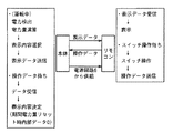
図1はこの発明の一実施形態の太陽光発電システム用パワーコンディショナの構成を示すブロック図である。図1において、太陽光発電システム用パワーコンディショナは、太陽電池1と、太陽電池1から得られた直流電力を交流電力に変換し、商用系統電源3に連系するインバータ部2と、インバータ部2を駆動するための駆動回路4および5と、太陽電池1からの直流電力を用いてインバータ部2に駆動電力を供給する主要電源部としての電源回路6と、商用系統電源3からの交流電力を直流電力に変換して用いる補助電源部としての電源回路7と、電源回路6から制御電源が供給され、インバータ部2に駆動信号を出力する制御回路8と、制御回路8と通信信号をやり取りし、インバータ部2の動作を遠隔制御する有線式リモートコントローラ9とから構成される。
【0017】
制御回路8はインバータ部2の電力制御を始め、パワーコンディショナ全体の制御を行なう回路であり、出力電力の演算および積算電力量,期間電力量,1日電力量,CO2削減量の演算を行ない、内蔵されている不揮発性のメモリにそれらの値を保存する。また、リモートコントローラ9には通常電源回路6から逆流防止用ダイオードD1を介して電力が制御電源として供給され、夜間など電源回路6からの電力供給が不可能な場合に限り、電源回路7から逆流防止用ダイオードD2を介してリモートコントローラ9に制御電源が供給される。
【0018】
インバータ部2は高周波絶縁回路を用いており、以下簡単にその構成と動作について説明する。太陽電池1から得られた直流電圧はインバータ部2内の高周波インバータ部10に与えられ、スイッチング素子により直流電圧が高周波交流電圧に変換される。変換された高周波交流電圧はトランス11に与えられて昇圧され、ダイオードブリッジ12によって全波整流されてDCフィルタ回路13に与えられる。
【0019】
DCフィルタ回路13は高周波成分を除去するリアクトルとコンデンサとで構成されており、このDCフィルタ回路13で高周波成分が除去された直流電圧は商用系統電源3の周期と同期した交流電圧に変換するスイッチング素子で構成された低周波インバータ部14に入力される。低周波インバータ部14からは交流電圧が発生され、その交流電圧はACフィルタ回路15に与えられ、高周波成分が除去される。ACフィルタ回路15で高周波成分が除去された交流電圧は系統リレー16を介して商用系統電源3に供給される。
【0020】
上述にごとく構成されたインバータ部2において、太陽電池1から入力された直流電圧は制御回路8で生成されたPWM制御信号によりスイッチング動作する高周波インバータ部10により高周波交流電圧に変換された後、トランス11によって絶縁および昇圧される。トランス11により昇圧された高周波交流電圧はダイオードブリッジ12により全波整流されて直流電圧となった後、DCフィルタ回路13により高周波成分が除去される。ここで、商用系統電源3の波形を全波整流した波形となり、さらに制御回路8で生成される商用系統電源3の周期と同期した折返し制御信号によりスイッチング動作する低周波インバータ部14により交流電圧に変換され、ACフィルタ回路15と連系リレー16とを介して商用系統電源3と連系する交流電圧が出力される。
【0021】
電源回路6は太陽電池1からの電力をインバータ部2と制御回路8とリモートコントローラ9に供給する。一方、電源回路7は電源回路6からの電源供給が不可能となった場合に、商用系統電源3からの電力をリモートコントローラ9に供給する。電源回路6,7としては、スイッチングレギュレータなどの方式が用いられる。
【0022】
図2は図1に示したリモートコントローラの構成を示すブロック図であり、図3はリモートコントローラの外観図である。
【0023】
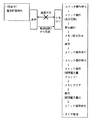
リモートコントローラ9は図2に示すように、記憶部としての内部メモリとタイマを内蔵する制御用マイクロコンピュータ(以下、制御用マイコンと称す)20と、その制御用マイコン20により制御される液晶モジュールとしての表示部17とを備えている。さらに、リモートコントローラ9は本体と接続するためのコネクタ19を有しており、このコネクタ19を介して本体から制御電源および通信信号がリモートコントローラ9に与えられる。コネクタ19の受信側通信信号用端子は、抵抗R1を介してフォトカプラ25の発光部の入力端子に接続され、発光部の他方の入力端子には制御電源が供給される。フォトカプラ25の受光素子の出力端子には、抵抗R2を介して制御電源が供給されるとともに、そのフォトカプラ25の出力端子が制御用マイコン20の入力端子に接続されている。
【0024】
一方、制御用マイコン20の出力端子には、抵抗R4を介してトランジスタTr1のベースが接続され、トランジスタTr1のコレクタは抵抗R3を介してコネクタ19の送信側通信信号用端子に接続されている。これらの抵抗R1〜R4とフォトカプラ25とトランジスタTr1によって通信回路が構成されている。本体の制御回路も同様の通信回路が内蔵されており、リモートコントローラ9との間で双方向で送受信が可能となっている。
【0025】
制御用マイコン20には操作スイッチ18が接続されている。操作スイッチ18は図3に示すように、「運転・停止切換」用の操作スイッチと、「連系/自立の運転モード切換」用の操作スイッチと、「環境貢献モニタ」用の操作スイッチと、「表示切換」用の操作スイッチと、「期間電力量リセット」用の操作スイッチが内蔵されている。
【0026】
また、液晶モジュールとしての表示部17の表示内容は、運転状態(運転・停止・待機・停電・日射不足・点検),運転モード(連系・自立),1日の1時間ごとの電力量の推移を表わすグラフ,運転時出力電力,設置からの積算電力量,ある期間内の期間電力量,1日の電力量,二酸化炭素削減量換算値,異常停止した場合のエラーコードの表示を含む。
【0027】
上述のごとく構成された太陽光発電システム用パワーコンディショナにおいて、運転時に表示部17に表示される内容は、本体の制御回路8で演算され、制御回路8から出力される情報は、その都度リモートコントローラ9によって受信されて表示部17に表示される。また、リモートコントローラ9で操作した内容は、その都度本体の制御回路8に送信される。これらの処理はリモートコントローラ9に内蔵されたマイコンにより制御され、それぞれのデータ通信は本体の制御回路8と2線でシリアルデータとして相互に行なわれる。
【0028】
図4はこの発明の一実施形態の太陽電池発電時の動作を示す図であり、図5は太陽電池出力低下時の動作を示す図であり、図6は太陽電池が発電しないとき(夜間)の動作を示す図であり、図7は太陽電池発電開始時の動作を示す図であり、図8は夜間に停電および復電したときの動作を示す図であり、図9は通信データフォーマットを示す図であり、図10は電力量推移を表わすグラフ表示である。
【0029】
次に、図1〜図10を参照して、この発明の一実施形態の具体的な動作について説明する。
【0030】
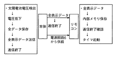
運転中は図4に示すように、本体が出力される電力を検出して電力量を演算する。そして、常時検出した出力電力データがリモートコントローラ9に送信され、リモートコントローラ9はその出力データを受信して表示部17に表示する。また、リモートコントローラ17は操作スイッチ18が操作されるまで待機しており、操作スイッチ18が操作されるとその操作情報を本体に送信する。リモートコントローラ9の表示部17の表示内容の選択は本体で決定され、電力量データがリモートコントローラ9に送信され、リモートコントローラ9はデータを受信し、表示を切換える。また、操作スイッチ18は期間電力量リセットスイッチが操作されると、本体に送信し、本体は期間電力量を0にするとともに、表示データとして0を送信する。リモートコントローラ9はデータを受信し、期間電力量を0と表示する。
【0031】
日射量が減少し、太陽電池1の出力が低下すると、制御回路8は太陽電池1の出力電圧の低下を検出し、太陽電池1の出力電圧が第1の所定電圧以下となったときに、インバータ部2にスイッチング素子をオフする信号を出力してインバータ部2を停止させる。
【0032】
このとき、図5に示すように、制御回路8は積算電力量,期間電力量,1日の電力量,二酸化炭素削減量の換算値,エラーコードなどのデータをリモートコントローラ9に記憶用として送信するとともに、制御回路8の内部不揮発性メモリに保存する。この時点で、リモートコントローラ9は制御回路8から送信された記憶用のデータを内部メモリに記憶する。その後、制御回路8はリモートコントローラ9との通信を終了し、リモートコントローラ9は制御回路8との通信が切れたことをトリガとしてタイマを起動させる。
【0033】
電源回路6は第1の所定電圧よりさらに低い第2の所定電圧を設けており、さらに、日射量が減少して太陽電池1の出力がさらに低下し、太陽電池1の出力電圧が第2の所定電圧以下になったとき、電源回路6は駆動電源および制御電源の出力を停止する。これにより、電源回路6はインバータ駆動回路4,5と制御回路8とリモートコントローラ9に電力を供給しなくなり、制御回路8が停止する。ただし、電源回路7からリモートコントローラ9に電力が供給されることにより、リモートコントローラ9は電源回路7からの電力により動作する。
【0034】
電源回路7からリモートコントローラ9に電力が供給される場合、図6に示すように、表示は操作スイッチ18を操作した場合のみ、第2メモリ内のデータを読出して表示する。電源回路6は第1の所定電圧よりさらに高い第3の所定電圧を設けており、翌朝などに日射量が回復し、太陽電池1の出力が復帰して太陽電池1の出力電圧が第3の所定電圧以上になったとき、図7に示すように電源回路6が動作を始め、インバータ部2と制御回路8とリモートコントローラ9に電源供給を再開し、運転を開始する。
【0035】
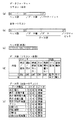
次に、通信データについて説明する。通信データは前述したようにシリアルで表わされ、リモートコントローラ9から本体に送られるデータフォーマットは図9(a)に示すように構成され、本体からリモートコントローラ9に送られるデータフォーマットは図9(b)に示すように構成されており、いずれもヘッダ部とデータ部とパリティビットとを含む。図9(c)はヘッダ部を示し、図9(d)はリモートコントローラ9から本体への通信データを示し、図9(e)は本体からリモートコントローラ9への通信データを示している。また、通信データにはデータ異常などを判別するために、決まった間隔(たとえば8ビットごと)で区切り信号(たとえば<“1”,“0”>)を挿入することにしている。
【0036】
前述のごとく、本体からリモートコントローラ9へ送信されるデータは表示内容を表わしている。ただしデータの中には電力を表わすものと積算電力量を表わすものなど種類があるため、本体からリモートコントローラ9へ送信されるデータ部は、データの種類と表示データにより構成され、データ種類別コードで後段のデータの種類を指定している。
【0037】
また、リモートコントローラ9から本体へ送信されるデータは操作内容を表わしている。これは、運転時(電源回路6から供給時)のスイッチ操作以外に、夜間(電源回路7から供給時)の動作状態を表わすものも含む。
【0038】
次に、上述の通信フォーマットに従って通信を行なう場合の通信回路の動作について説明する。通信回路において、図9(c)で“1”で表している信号は送信側のトランジスタをオンする信号である。このとき、受信側のフォトカプラの出力はオンすることになり、受信側では信号は「L」レベルとなる。“0”で表わしている信号はこの逆となる。したがって、通信データを送信していない場合は、表中“0”で表わしている信号であり、受信側では信号は「H」となっており、ヘッダ部の“1”(受信側「L」)により、データの始まりを確認する。
【0039】
次に、制御回路8の通信終了再開をリモートコントローラ9が判別する方法について説明する。制御回路8が通信を断つ場合、本体の制御回路8の通信回路の送信用トランジスタをオフ状態(データで表わすと“0”)にして継続する。このとき、受信側であるリモートコントローラ9は「H」レベル信号を受信し続ける。前述のごとく、データには決まった間隔で区切り信号が入ることから、正常な通信であればリモートコントローラ9が「H」レベル信号を受信し続けることはなく、これによりリモートコントローラ9は通信が終了したことを判別する。リモートコントローラ9は通信が終了したことを判別すると、リモートコントローラ9の送信用トランジスタをオフ状態(データで表わすと“0”)にして継続する。これは電源回路6が停止した場合、あるいは通信ケーブルが断絶した場合と同じ状況である。
【0040】
また、通信再開は、本体の制御回路8の通信回路の送信用トランジスタをオン状態(データで表わすと“1”)を一定時間継続させることにより判別し、運転再開時に行なう。
【0041】
また、通信ケーブルが断線した場合の処理について説明する。制御回路8からリモートコントローラ9への送信信号ケーブルが断線した場合、たとえばインバータが運転中であったとしても、リモートコントローラ9は前述のごとく制御回路8がインバータ2を停止させ、通信を終了したと判別する。
【0042】
一方、制御回路8は表示データを送信しているものとしてインバータ部2の運転を継続してしまう。ここで、前述したように、リモートコントローラ9は制御回路8が通信を終了したと判別すると、リモートコントローラ9側も同様の状態にすることにより、制御回路8側がケーブル断線としてインバータ部2を停止させる。逆に、リモートコントローラ9または御回路8の送信信号ケーブルが断線した場合、制御回路8側が直接ケーブル断線を判別し、インバータ部2を停止させる。これにより、ケーブル断線時にはインバータ部2を完全に停止させることができる。
【0043】
次に、リモートコントローラ9のタイマについて説明する。リモートコントローラ9のタイマはインバータ部2が停止している時間(本体終了時間=夜間)を管理しており、図5で説明したように、制御回路8との通信が切れたことをトリガとしてタイマが起動する。
【0044】
次に、図7に示すように、本体制御回路8との通信が再開した時点でタイマが動作しているかあるいはタイマが停止しているかを、通信側再開時に本体制御回路8へ送信する。
【0045】
タイマ時間は夜間の時間を意味するから、タイマ時間を6時間とすると6時間経過後にタイマが停止する。6時間以上経過後に運転が再開し、本体との通信が再開すれば1日経過したこととする。制御回路8は通信再開時にタイマ停止のデータを受ければ、制御回路8の内部メモリに保存している1日の電力量をクリアし、タイマ動作中のデータを受ければ、1日経過していないものとし、1日の電力量はクリアせず、継続して積算する。
【0046】
前述のごとく、太陽電池1の出力電圧が第1の所定電圧以下になった通信を終了した時点から、前述の第3の所定電圧以上で1通信が再開するまでの時間をタイマで管理するのは、前述の太陽電池1の出力電圧が第1の所定電圧以下になっても太陽電池1の特性上日射量がすぐに復帰し、太陽電池1の出力電圧が運転を開始する前日の第3の所定電圧以上になってしまう場合があるからである。特に、日没付近は太陽電池1の出力電流は極少となり、太陽電池1の出力電圧が第2の所定電圧以下になって、電源回路6が停止した時点で太陽電池1は開放電圧をとり、開放電圧が第3の所定電圧以上となっていれば再起動してしまう。再起動してもまた太陽電池1の出力電流はとることができず停止し、これを繰返すことになる。このたびに1日のデータをクリアしてしまうとほとんどの場合、終了時に1日のデータがクリアされてしまい、当日の電流量データが残らない(夜間に確認できない)ことになる。したがって、この現象を防ぐためにタイマで時間を管理している。
【0047】
次に、電流量の推移を表わすグラフ表示について説明する。
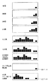
図10に示すように、この表示は1時間ごとの積算電流量をインジケータで表示し、一定時間分表示するものであり、時間経過に伴い右側からインジケータ表示が移動する。したがって、一定時間以上運転している場合、最新の時間分を表示できる。この実施形態では、5段階,12時間分表示する。
【0048】
運転時に本体制御回路8で1時間の電力量の演算を行ない、1時間ごとにリモートコントローラ9へグラフデータ(0〜5)を送信する。リモートコントローラ9はデータを受信すると最新データを内部メモリに保存するとともに表示部17の右端に表示する。リモートコントローラ9は12時間分のデータを保存することができ、内部メモリは受信ごとにデータを更新し、表示するグラフは本体の受信ごとに更新される。
【0049】
インバータ部2の停止後は、リモートコントローラ9が次のデータを受信するまで内部メモリのデータが保持され、表示も固定される。前述のごとく停止後のタイマ状態により、1日経過したことを判別するためにタイマ停止後に本体が起動し、次のグラフデータを受信した場合、表示をクリアし、初めから表示する。タイマ完了前に本体が起動し、グラフデータを受信した場合、タイマ時間分のインジケータ0(表示なし)とし、その続きから表示する。
【0050】
次に、夜間におけるリモートコントローラの操作について説明する。図6に示すように、「環境貢献モニタ」用の操作スイッチと、「表示切換」用の操作スイッチといった表示に関するスイッチを操作した場合、前述のごとく内部メモリに記憶されたデータを表示する。
【0051】
表示以外のスイッチが操作された場合、「期間電力量リセット」用の操作スイッチを操作した場合、まず記憶していた内部データを0とし、かつスイッチ操作されたことを保存する。翌朝、本体を起動した時の初期通信時に、期間電流量リセット信号を本体へ送信し、制御回路8が通信再開時に夜間操作内容を送信し、本体側データをクリアする。「運転モード切換」用の操作スイッチを操作したときも同様である。
【0052】
次に、夜間停電し、電源回路7が停止した場合の動作について説明する。図8に示すように、電源回路7が停止するためにリモートコントローラ9は動作しなくなり、復電した場合、リモートコントローラ9は動作可能となるが、本体から受信して内部メモリに記憶していたデータは消去されてしまう。また、期間電流量リセット操作が行なわれていても無効となる。内部メモリに夜間表示するデータがない場合、表示はバーとする。また、この場合、タイマが復電しても起動させず、翌朝本体起動時に初期通信時タイマ停止のデータを送信し、1日経過したものとする。
【0053】
図11はこの発明の第2の実施形態の太陽光発電システム用パワーコンディショナを示すブロック図である。この図11に示した第2実施形態の太陽光発電システム用パワーコンディショナは、図1に示した商用電源3からの電力に基づいてリモートコントローラ9に直流電力を供給する電源回路7を省略したものであり、それ以外の構成は図1と同じである。
【0054】
図12はリモートコントローラの他の例を示すブロック図である。この図12に示したリモートコントローラは、補助電源22としての電池とダイオードとを設けたものであり、電池の正極にダイオードのアノードが接続され、ダイオードのカソードはコネクタの電源端子から同じくダイオードを介したカソードと接続され、リモートコントローラ9の制御電源を供給している。インバータ部2が停止した場合、リモートコントローラ9は内部の補助電源部22からの電源により動作する。その動作内容については図2に示したリモートコントローラと同じである。
【0055】
上述のごとく、停止している時間をタイマで管理することで、時計機能を用いずに、簡単に1日のデータを管理でき、また1日の発電開始からの電力量を演算および表示することができる。
【0056】
今回開示された実施の形態はすべての点で例示であって制限的なものではないと考えられるべきである。本発明の範囲は上記した説明ではなくて特許請求の範囲によって示され、特許請求の範囲と均等の意味および範囲内でのすべての変更が含まれることが意図される。
【0057】
【発明の効果】
以上のように、この発明によれば、太陽電池の電力をインバータで交流電力に変換し、商用系統電源に連系する太陽光発電システム用パワーコンディショナにおいて、インバータが停止している時間を管理し、指定時間以上であれば1日経過したと判断し、1日分のデータをクリアし、新たにデータを記憶することにより時計機能を内蔵させることなく、時刻を設定する手間を省くことができ、パワーコンディショナの日ごとの情報を確認することができる。
【0058】
また、インバータが運転中、規定時間ごとの電力量を一定数グラフ表示する表示部を設け、時間経過に伴い表示の最新データを更新し、過去のデータを順次移動させ、インバータが停止中はデータを更新せず表示を固定することにより、1日の発電開始から発電終了までの電力量の推移について確認することができる。
【0059】
時間を管理するタイマは、太陽電池以外の電源により動作することにより、夜間時間を管理することができ、太陽光発電システム用パワーコンディショナの日ごとの情報を確認することができる。また、停電や電池交換の場合も改めて時刻設定をする手間がかからない。
【0060】
さらに、リモートコントローラを設けたことによって、インバータ運転中は太陽電池により動作し、インバータ停止中の操作内容をインバータ起動時に転送することにより、太陽光発電システム用パワーコンディショナから離れた位置で操作および表示を確認することが可能となり、太陽電池が発電していない状態でのリモートコントローラの操作を太陽電池が発電を再開し、インバータ運転時に反映することができる。
【図面の簡単な説明】
【図1】 この発明の一実施形態の構成を示すブロック図である。
【図2】 図1に示したリモートコントローラの構成を示すブロック図である。
【図3】 リモートコントローラの外観図である。
【図4】 太陽電池発電時の動作を示す図である。
【図5】 太陽電池出力低下時の動作を示す図である。
【図6】 太陽電池が発電していないとき(夜間)の動作を示す図である。
【図7】 太陽電池発電開始時の動作を示す図である。
【図8】 夜間に停電および復電したときの動作を示す図である。
【図9】 通信データのフォーマットを示す図である。
【図10】 電力量の推移を表わすグラフ表示の一例を示す図である。
【図11】 この発明の第2の実施形態の構成を示すブロック図である。
【図12】 図11に示したリモートコントローラの構成を示すブロック図である。
【符号の説明】
1 太陽電池、2 インバータ部、3 商用系統電源、4,5 インバータ駆動回路、6,7 電源回路、8 制御回路、9 リモートコントローラ、10 高周波インバータ、11 トランス、12 ダイオードブリッジ、13 DCフィルタ回路、14 低周波インバータ、15 ACフィルタ回路、16 連系リレー、17 表示部、18 操作スイッチ、19 コネクタ、20 制御用マイコン、21 通信回路。[0001]
BACKGROUND OF THE INVENTION
The present invention relates to a power conditioner for a solar power generation system, and more particularly to a power conditioner for a solar power generation system that converts direct current power obtained by a solar cell into alternating current power and is linked to a commercial power source.
[0002]
[Prior art]
In general, a power conditioner for a photovoltaic power generation system includes an inverter section as a main circuit, an inverter drive circuit section, a control circuit section, a display section, an operation section, and a power supply circuit that supplies necessary power to these sections. It consists of a part. The display unit displays the instantaneous output power and integrated power of the power conditioner detected and calculated by the control circuit unit, or the amount of power that can be initialized arbitrarily by the user. In addition, for those that display the amount of power for a fixed time such as one day or one month, they have a clock and calendar function, and the built-in timer determines the time and time. If the power from the solar cell is converted and supplied to each circuit, the power supply circuit is supplied from a nighttime backup power supply for a timer or a commercial power supply.
[0003]
As another conventional method, as described in Japanese Patent Application Laid-Open No. 2000-304779, there is a method that does not have a clock function and calculates and displays the amount of power per day using a timer. In the night operation, a power supply circuit supplied from a night backup power source or a commercial power source is used, and the stored display contents are merely displayed in accordance with the operation, and operations such as data update are not performed.
[0004]
[Problems to be solved by the invention]
The photovoltaic power generation system aims to reduce the power consumption of commercial power sources by preferentially using the power generated by solar cells, and when the generated power exceeds the power consumed in the home, the reverse power flow And it is possible to sell power to the power company. Therefore, the amount of generated power is important information for consumers.
[0005]
Since the generated power of a solar cell changes depending on the amount of solar radiation and a constant output is not obtained, it is difficult to predict the amount of power from time. For this reason, it is functionally significant to confirm the amount of generated power and its transition for consumers.
[0006]
However, in the conventional method having no clock function, when the daily power amount is known, it takes time and effort to read and subtract the integrated power amount display every day or initialize the period power amount every day.
[0007]
In addition, the conventional method with a built-in clock function can automatically calculate and display the amount of power per day, but it cannot obtain correct information unless the time is accurate. Setting is required. When a commercial power supply is used as the internal power supply, if a power failure occurs, it is necessary to make a new setting after the power failure. Even when a battery is used as the power source of the timer, it is necessary to change the battery and set the time due to battery consumption, and there is a problem that it takes time and effort.
[0008]
Moreover, in the conventional method of measuring time by using a timer instead of the clock function and calculating and displaying the electric energy, one day is from 24 hours before to the present, and the electric energy is the electric power from the start of power generation on the day. It is not the amount, but the amount of power for 24 hours. That is, for example, if the daily power amount is confirmed at noon, it is the power amount from noon yesterday to the present day, and the power amount from the start of power generation on that day to noon cannot be known.
[0009]
In addition, at night when the solar battery does not generate power, if the power supply circuit converts the power from the solar battery and supplies it to each circuit, the control circuit of the power conditioner operates when the remote controller is operated. In this case, there is a problem that the operation is not accepted, or the operation content is not reflected and becomes invalid.
[0010]
Therefore, a main object of the present invention is to provide a power conditioner for a photovoltaic power generation system that does not have a clock function and does not require time setting, and that can display power generation information such as the amount of power of solar power generation per day. Is to provide.
[0011]
[Means for Solving the Problems]
The present invention includes a memory for storing data for one day in a power conditioner for a photovoltaic power generation system that converts electric power generated by a solar cell into AC power by an inverter and is linked to a commercial power supply. It is characterized by including control means for managing the time of stoppage and determining that one day has passed if it is equal to or more than a predetermined time, and clearing the memory and storing new data in the memory.
[0012]
Further, the inverter includes a display unit that displays a predetermined number of graphs of electric energy for each predetermined time while the inverter is in operation, and the control unit updates data displayed on the display unit as time passes, The data is sequentially moved, and the display is fixed without updating the data while the inverter is stopped.
[0013]
Furthermore, it is characterized by including a remote controller for remotely giving a control command away from the control means.
[0014]
In addition, the remote controller performs time management when the inverter is stopped, and the time management is operated by electric power from a commercial power supply.
[0015]
Further, the remote controller operates with power from the solar battery during operation of the inverter, and transfers the operation content while the inverter is stopped to the control means when the inverter is activated.
[0016]
DETAILED DESCRIPTION OF THE INVENTION
FIG. 1 is a block diagram showing a configuration of a power conditioner for a photovoltaic power generation system according to an embodiment of the present invention. In FIG. 1, a power conditioner for a photovoltaic power generation system includes a
[0017]
The
[0018]
The
[0019]
The
[0020]
In the
[0021]
The
[0022]
2 is a block diagram showing the configuration of the remote controller shown in FIG. 1, and FIG. 3 is an external view of the remote controller.
[0023]
As shown in FIG. 2, the
[0024]
On the other hand, the base of the transistor Tr1 is connected to the output terminal of the
[0025]
An
[0026]
In addition, the display contents of the
[0027]
In the power conditioner for the photovoltaic power generation system configured as described above, the content displayed on the
[0028]
FIG. 4 is a diagram showing the operation at the time of solar cell power generation according to one embodiment of the present invention, FIG. 5 is a diagram showing the operation at the time of solar cell output reduction, and FIG. 6 is when the solar cell does not generate power (at night). FIG. 7 is a diagram showing the operation at the start of solar cell power generation, FIG. 8 is a diagram showing the operation when a power failure and power recovery occur at night, and FIG. 9 shows the communication data format. FIG. 10 is a graph showing the transition of electric energy.
[0029]
Next, with reference to FIGS. 1-10, the specific operation | movement of one Embodiment of this invention is demonstrated.
[0030]
As shown in FIG. 4, during operation, the power output from the main body is detected and the amount of power is calculated. Then, the constantly detected output power data is transmitted to the
[0031]
When the amount of solar radiation decreases and the output of the
[0032]
At this time, as shown in FIG. 5, the
[0033]
The
[0034]
When power is supplied from the power supply circuit 7 to the
[0035]
Next, communication data will be described. The communication data is expressed serially as described above, the data format sent from the
[0036]
As described above, data transmitted from the main body to the
[0037]
The data transmitted from the
[0038]
Next, the operation of the communication circuit when performing communication according to the communication format described above will be described. In the communication circuit, the signal represented by “1” in FIG. 9C is a signal for turning on the transmission side transistor. At this time, the output of the photocoupler on the receiving side is turned on, and the signal is at the “L” level on the receiving side. The signal represented by “0” is the opposite. Therefore, when communication data is not transmitted, the signal is represented by “0” in the table, the signal is “H” on the reception side, and “1” (reception side “L” in the header portion). ) To confirm the start of the data.
[0039]
Next, a method for the
[0040]
The communication is restarted by determining that the transmission transistor of the communication circuit of the
[0041]
A process when the communication cable is disconnected will be described. When the transmission signal cable from the
[0042]
On the other hand, the
[0043]
Next, the timer of the
[0044]
Next, as shown in FIG. 7, whether the timer is operating or the timer is stopped when communication with the main
[0045]
Since the timer time means night time, if the timer time is 6 hours, the timer stops after 6 hours. If the operation resumes after the elapse of 6 hours or more and communication with the main body resumes, one day has passed. If the
[0046]
As described above, the time from when the communication when the output voltage of the
[0047]
Next, the graph display showing the transition of the current amount will be described.
As shown in FIG. 10, this display displays an accumulated current amount for every hour with an indicator and displays it for a certain time, and the indicator display moves from the right side as time elapses. Therefore, when operating for a certain time or more, the latest time can be displayed. In this embodiment, 5 levels and 12 hours are displayed.
[0048]
During operation, the main
[0049]
After the
[0050]
Next, the operation of the remote controller at night will be described. As shown in FIG. 6, when an operation switch for "environmental contribution monitor" and an operation switch for "display switching" are operated, the data stored in the internal memory is displayed as described above.
[0051]
When a switch other than the display is operated, when an operation switch for “period power consumption reset” is operated, the stored internal data is first set to 0, and the switch operation is saved. The next morning, during the initial communication when the main body is activated, a period current amount reset signal is transmitted to the main body, and the
[0052]
Next, the operation when a power failure occurs at night and the power supply circuit 7 stops will be described. As shown in FIG. 8, since the power supply circuit 7 is stopped, the
[0053]
FIG. 11: is a block diagram which shows the power conditioner for solar power generation systems of 2nd Embodiment of this invention. The power conditioner for a photovoltaic power generation system according to the second embodiment shown in FIG. 11 omits the power supply circuit 7 for supplying DC power to the
[0054]
FIG. 12 is a block diagram showing another example of the remote controller. The remote controller shown in FIG. 12 is provided with a battery and a diode as the
[0055]
As described above, by managing the time of stoppage with a timer, it is possible to easily manage the data for one day without using the clock function, and to calculate and display the amount of power from the start of power generation on the first day. Can do.
[0056]
The embodiment disclosed this time should be considered as illustrative in all points and not restrictive. The scope of the present invention is defined by the terms of the claims, rather than the description above, and is intended to include any modifications within the scope and meaning equivalent to the terms of the claims.
[0057]
【The invention's effect】
As described above, according to the present invention, the power of the solar cell is converted into AC power by the inverter, and the inverter is stopped in the power conditioner for the photovoltaic power generation system linked to the commercial power supply. If it is longer than the specified time, it is determined that one day has passed, and data for one day is cleared, and new data is stored to save time and effort for setting the time. Yes, you can check the information of the inverter every day.
[0058]
In addition, a display unit that displays a fixed number of graphs of the amount of power per specified time while the inverter is in operation is provided, the latest data displayed is updated as time passes, and past data is moved sequentially. By fixing the display without updating, it is possible to check the transition of the electric energy from the start of power generation to the end of power generation on the 1st.
[0059]
The timer for managing the time can manage the night time by operating with a power source other than the solar battery, and can confirm the information for each day of the power conditioner for the solar power generation system. Also, there is no need to set the time again in the event of a power failure or battery replacement.
[0060]
Furthermore, by providing a remote controller, the inverter operates with solar cells, and when the inverter is stopped, the operation details are transferred when the inverter is started. The display can be confirmed, and the operation of the remote controller in a state where the solar cell is not generating power can be reflected in the inverter operation by the solar cell restarting power generation.
[Brief description of the drawings]
FIG. 1 is a block diagram showing a configuration of an embodiment of the present invention.
FIG. 2 is a block diagram showing a configuration of a remote controller shown in FIG.
FIG. 3 is an external view of a remote controller.
FIG. 4 is a diagram showing an operation during solar cell power generation.
FIG. 5 is a diagram showing an operation when the output of a solar cell is lowered.
FIG. 6 is a diagram showing an operation when the solar cell is not generating power (at night).
FIG. 7 is a diagram showing an operation at the start of solar cell power generation.
FIG. 8 is a diagram illustrating an operation when a power failure and power recovery occur at night.
FIG. 9 is a diagram showing a format of communication data.
FIG. 10 is a diagram showing an example of a graph display showing transition of electric energy.
FIG. 11 is a block diagram showing a configuration of a second embodiment of the present invention.
12 is a block diagram showing a configuration of the remote controller shown in FIG. 11. FIG.
[Explanation of symbols]
DESCRIPTION OF
Claims (4)
1日分のデータを記憶するメモリを含み、前記インバータが停止している時間を管理し、既定時間以上であれば1日を経過したものと判断して前記メモリをクリアし、新たなデータを前記メモリに記憶させる制御手段を備えたことを特徴とする、太陽光発電システム用パワーコンディショナ。In a power conditioner for a photovoltaic power generation system that converts electric power generated by a solar cell into AC power by an inverter and links to a commercial power supply.
It includes a memory for storing data for one day, manages the time when the inverter is stopped, and if it is longer than a predetermined time, it is judged that one day has passed, the memory is cleared, and new data is stored. A power conditioner for a photovoltaic power generation system, comprising control means for storing in the memory.
前記制御手段は、時間の経過に伴って前記表示部に表示されるデータを更新し、前記グラフ上で過去のデータを順次移動させ、前記インバータが停止中はデータを更新せず表示を固定することを特徴とする、請求項1に記載の太陽光発電システム用パワーコンディショナ。In addition, the inverter includes a display unit that displays a predetermined number of graphs of electric energy per predetermined time during operation,
The control unit updates data displayed on the display unit as time passes, sequentially moves past data on the graph, and fixes the display without updating data while the inverter is stopped. The power conditioner for a photovoltaic power generation system according to claim 1, wherein
前記リモートコントローラは、前記インバータの運転中は前記太陽電池からの電力で動作し、前記インバータ停止中の操作内容を前記インバータ起動時に前記制御手段に転送することを特徴とする、請求項1または2に記載の太陽光発電システム用パワーコンディショナ。Furthermore, look including a remote controller for providing remotely control command away from said control means,
The remote controller operates with power from the solar cell during operation of the inverter, and transfers the operation content while the inverter is stopped to the control means when the inverter is activated. The power conditioner for photovoltaic power generation systems described in 1.
Priority Applications (2)
| Application Number | Priority Date | Filing Date | Title |
|---|---|---|---|
| JP2001114966A JP3772096B2 (en) | 2001-04-13 | 2001-04-13 | Power conditioner for photovoltaic system |
| US10/120,831 US6570270B2 (en) | 2001-04-13 | 2002-04-12 | Power conditioner for solar power generation system |
Applications Claiming Priority (1)
| Application Number | Priority Date | Filing Date | Title |
|---|---|---|---|
| JP2001114966A JP3772096B2 (en) | 2001-04-13 | 2001-04-13 | Power conditioner for photovoltaic system |
Publications (2)
| Publication Number | Publication Date |
|---|---|
| JP2002315194A JP2002315194A (en) | 2002-10-25 |
| JP3772096B2 true JP3772096B2 (en) | 2006-05-10 |
Family
ID=18965940
Family Applications (1)
| Application Number | Title | Priority Date | Filing Date |
|---|---|---|---|
| JP2001114966A Expired - Fee Related JP3772096B2 (en) | 2001-04-13 | 2001-04-13 | Power conditioner for photovoltaic system |
Country Status (2)
| Country | Link |
|---|---|
| US (1) | US6570270B2 (en) |
| JP (1) | JP3772096B2 (en) |
Families Citing this family (78)
| Publication number | Priority date | Publication date | Assignee | Title |
|---|---|---|---|---|
| JP3855914B2 (en) * | 2002-11-12 | 2006-12-13 | 株式会社日立製作所 | Linear drive |
| JP4508659B2 (en) * | 2004-01-13 | 2010-07-21 | 三洋電機株式会社 | Inverter for grid connection |
| GB2415841B (en) | 2004-11-08 | 2006-05-10 | Enecsys Ltd | Power conditioning unit |
| JP4794189B2 (en) * | 2005-03-30 | 2011-10-19 | 三洋電機株式会社 | Solar power plant |
| US7511451B2 (en) * | 2005-07-07 | 2009-03-31 | Gerald Pierce | Electrical energy source |
| US10693415B2 (en) | 2007-12-05 | 2020-06-23 | Solaredge Technologies Ltd. | Testing of a photovoltaic panel |
| US11881814B2 (en) | 2005-12-05 | 2024-01-23 | Solaredge Technologies Ltd. | Testing of a photovoltaic panel |
| JP4678340B2 (en) * | 2006-06-19 | 2011-04-27 | パナソニック電工株式会社 | Charged particle supply device |
| JP2008059084A (en) * | 2006-08-29 | 2008-03-13 | Toshiba Kyaria Kk | System interconnection inverter |
| US8384243B2 (en) | 2007-12-04 | 2013-02-26 | Solaredge Technologies Ltd. | Distributed power harvesting systems using DC power sources |
| US11855231B2 (en) | 2006-12-06 | 2023-12-26 | Solaredge Technologies Ltd. | Distributed power harvesting systems using DC power sources |
| US9088178B2 (en) | 2006-12-06 | 2015-07-21 | Solaredge Technologies Ltd | Distributed power harvesting systems using DC power sources |
| US8963369B2 (en) | 2007-12-04 | 2015-02-24 | Solaredge Technologies Ltd. | Distributed power harvesting systems using DC power sources |
| US8816535B2 (en) | 2007-10-10 | 2014-08-26 | Solaredge Technologies, Ltd. | System and method for protection during inverter shutdown in distributed power installations |
| US8473250B2 (en) | 2006-12-06 | 2013-06-25 | Solaredge, Ltd. | Monitoring of distributed power harvesting systems using DC power sources |
| US8319483B2 (en) | 2007-08-06 | 2012-11-27 | Solaredge Technologies Ltd. | Digital average input current control in power converter |
| US11296650B2 (en) | 2006-12-06 | 2022-04-05 | Solaredge Technologies Ltd. | System and method for protection during inverter shutdown in distributed power installations |
| US8947194B2 (en) | 2009-05-26 | 2015-02-03 | Solaredge Technologies Ltd. | Theft detection and prevention in a power generation system |
| US8013472B2 (en) | 2006-12-06 | 2011-09-06 | Solaredge, Ltd. | Method for distributed power harvesting using DC power sources |
| US11888387B2 (en) | 2006-12-06 | 2024-01-30 | Solaredge Technologies Ltd. | Safety mechanisms, wake up and shutdown methods in distributed power installations |
| US9130401B2 (en) | 2006-12-06 | 2015-09-08 | Solaredge Technologies Ltd. | Distributed power harvesting systems using DC power sources |
| US8319471B2 (en) | 2006-12-06 | 2012-11-27 | Solaredge, Ltd. | Battery power delivery module |
| US11728768B2 (en) | 2006-12-06 | 2023-08-15 | Solaredge Technologies Ltd. | Pairing of components in a direct current distributed power generation system |
| US11309832B2 (en) | 2006-12-06 | 2022-04-19 | Solaredge Technologies Ltd. | Distributed power harvesting systems using DC power sources |
| US8618692B2 (en) | 2007-12-04 | 2013-12-31 | Solaredge Technologies Ltd. | Distributed power system using direct current power sources |
| US9112379B2 (en) | 2006-12-06 | 2015-08-18 | Solaredge Technologies Ltd. | Pairing of components in a direct current distributed power generation system |
| US11687112B2 (en) | 2006-12-06 | 2023-06-27 | Solaredge Technologies Ltd. | Distributed power harvesting systems using DC power sources |
| US11735910B2 (en) | 2006-12-06 | 2023-08-22 | Solaredge Technologies Ltd. | Distributed power system using direct current power sources |
| US11569659B2 (en) | 2006-12-06 | 2023-01-31 | Solaredge Technologies Ltd. | Distributed power harvesting systems using DC power sources |
| US8300439B2 (en) * | 2007-03-07 | 2012-10-30 | Greenray Inc. | Data acquisition apparatus and methodology for self-diagnosing of AC modules |
| US9291696B2 (en) | 2007-12-05 | 2016-03-22 | Solaredge Technologies Ltd. | Photovoltaic system power tracking method |
| EP2232690B1 (en) | 2007-12-05 | 2016-08-31 | Solaredge Technologies Ltd. | Parallel connected inverters |
| US11264947B2 (en) | 2007-12-05 | 2022-03-01 | Solaredge Technologies Ltd. | Testing of a photovoltaic panel |
| CN101933209B (en) | 2007-12-05 | 2015-10-21 | 太阳能安吉有限公司 | Release mechanism in distributed electrical power apparatus, to wake up and method for closing |
| US8049523B2 (en) | 2007-12-05 | 2011-11-01 | Solaredge Technologies Ltd. | Current sensing on a MOSFET |
| WO2009118682A2 (en) | 2008-03-24 | 2009-10-01 | Solaredge Technolgies Ltd. | Zero current switching |
| WO2009136358A1 (en) | 2008-05-05 | 2009-11-12 | Solaredge Technologies Ltd. | Direct current power combiner |
| JP5077958B2 (en) * | 2008-06-16 | 2012-11-21 | シャープ株式会社 | Power generation system |
| JP5202159B2 (en) * | 2008-07-28 | 2013-06-05 | 三菱電機株式会社 | Data display device and data display method |
| JP5270681B2 (en) * | 2008-09-18 | 2013-08-21 | 株式会社三社電機製作所 | Inverter for grid connection |
| JP5412856B2 (en) * | 2009-01-30 | 2014-02-12 | Tdk株式会社 | Bidirectional converter |
| AT508106B1 (en) * | 2009-02-12 | 2012-09-15 | Fronius Int Gmbh | INVERTER FOR A PHOTOVOLTAIC SYSTEM WITH STRUCTURE MONITORING AND STRUCTURE MONITORING METHOD |
| CN201378812Y (en) * | 2009-02-23 | 2010-01-06 | 中山大洋电机股份有限公司 | Power-supply control device and ventilation and air-exchange device employing same |
| CN101777775A (en) * | 2010-02-26 | 2010-07-14 | 东南大学 | High-frequency isolation single-phase photovoltaic grid-connected system and control method thereof |
| GB2485335B (en) | 2010-10-25 | 2012-10-03 | Enecsys Ltd | Renewable energy monitoring system |
| US10230310B2 (en) | 2016-04-05 | 2019-03-12 | Solaredge Technologies Ltd | Safety switch for photovoltaic systems |
| US10673229B2 (en) | 2010-11-09 | 2020-06-02 | Solaredge Technologies Ltd. | Arc detection and prevention in a power generation system |
| US10673222B2 (en) | 2010-11-09 | 2020-06-02 | Solaredge Technologies Ltd. | Arc detection and prevention in a power generation system |
| GB2485527B (en) | 2010-11-09 | 2012-12-19 | Solaredge Technologies Ltd | Arc detection and prevention in a power generation system |
| JP5677823B2 (en) * | 2010-12-08 | 2015-02-25 | 京セラ株式会社 | Monitoring device and monitoring method |
| GB2486408A (en) | 2010-12-09 | 2012-06-20 | Solaredge Technologies Ltd | Disconnection of a string carrying direct current |
| GB2483317B (en) | 2011-01-12 | 2012-08-22 | Solaredge Technologies Ltd | Serially connected inverters |
| BR112013006740A2 (en) * | 2011-07-15 | 2019-09-24 | Nec Corp | battery system operable in conjunction with a mains and method of controlling a battery system |
| US8570005B2 (en) | 2011-09-12 | 2013-10-29 | Solaredge Technologies Ltd. | Direct current link circuit |
| GB2498365A (en) | 2012-01-11 | 2013-07-17 | Solaredge Technologies Ltd | Photovoltaic module |
| US9853565B2 (en) | 2012-01-30 | 2017-12-26 | Solaredge Technologies Ltd. | Maximized power in a photovoltaic distributed power system |
| GB2498791A (en) | 2012-01-30 | 2013-07-31 | Solaredge Technologies Ltd | Photovoltaic panel circuitry |
| GB2498790A (en) | 2012-01-30 | 2013-07-31 | Solaredge Technologies Ltd | Maximising power in a photovoltaic distributed power system |
| JP6017150B2 (en) * | 2012-02-28 | 2016-10-26 | シャープ株式会社 | Power supply switching device, remote control device, and photovoltaic power generation system |
| GB2499991A (en) | 2012-03-05 | 2013-09-11 | Solaredge Technologies Ltd | DC link circuit for photovoltaic array |
| JP2013187917A (en) * | 2012-03-05 | 2013-09-19 | Sharp Corp | Remote controller, solar power generation system, energy system, control method of remote controller, control program, and computer readable recording medium |
| US10115841B2 (en) | 2012-06-04 | 2018-10-30 | Solaredge Technologies Ltd. | Integrated photovoltaic panel circuitry |
| US9502902B2 (en) | 2012-06-26 | 2016-11-22 | Solarcity Corporation | System, method and apparatus for generating layout of devices in solar installations |
| JP6157126B2 (en) * | 2013-01-23 | 2017-07-05 | 京セラ株式会社 | Power control apparatus, power control system, remote unit, and power control method |
| JP6082886B2 (en) * | 2013-02-22 | 2017-02-22 | 株式会社高砂製作所 | Power adjustment apparatus and power adjustment method |
| US9548619B2 (en) | 2013-03-14 | 2017-01-17 | Solaredge Technologies Ltd. | Method and apparatus for storing and depleting energy |
| US9941813B2 (en) | 2013-03-14 | 2018-04-10 | Solaredge Technologies Ltd. | High frequency multi-level inverter |
| EP3506370B1 (en) | 2013-03-15 | 2023-12-20 | Solaredge Technologies Ltd. | Bypass mechanism |
| JP6287109B2 (en) * | 2013-11-26 | 2018-03-07 | 株式会社ノーリツ | Inverter |
| US9318974B2 (en) | 2014-03-26 | 2016-04-19 | Solaredge Technologies Ltd. | Multi-level inverter with flying capacitor topology |
| JP2016005408A (en) * | 2014-06-18 | 2016-01-12 | 三菱電機株式会社 | Power converter and power conversion system |
| JP6341783B2 (en) * | 2014-07-17 | 2018-06-13 | 三菱電機株式会社 | Inverter for photovoltaic power generation |
| JP6320240B2 (en) * | 2014-08-21 | 2018-05-09 | 三菱電機株式会社 | Solar power system |
| EP3264557B1 (en) * | 2015-02-25 | 2020-11-04 | KYOCERA Corporation | Power conditioning system and power conditioning method |
| JP6153663B1 (en) * | 2015-11-20 | 2017-06-28 | 田淵電機株式会社 | Relay abnormality detection device and power conditioner |
| US11018623B2 (en) | 2016-04-05 | 2021-05-25 | Solaredge Technologies Ltd. | Safety switch for photovoltaic systems |
| US11177663B2 (en) | 2016-04-05 | 2021-11-16 | Solaredge Technologies Ltd. | Chain of power devices |
| CN111031647B (en) * | 2019-12-30 | 2022-04-15 | 国网北京市电力公司 | Street lamp on-site decentralized monitoring control method and storage medium |
Family Cites Families (4)
| Publication number | Priority date | Publication date | Assignee | Title |
|---|---|---|---|---|
| US4253764A (en) * | 1978-02-10 | 1981-03-03 | Morrill Ralph A | Solar energy metering and recording system |
| US4678330A (en) * | 1985-04-30 | 1987-07-07 | The United States Of America As Represented By The United States Department Of Energy | Method and apparatus for measuring solar radiation in a vegetative canopy |
| US5555927A (en) * | 1995-06-07 | 1996-09-17 | Honeywell Inc. | Thermostat system having an optimized temperature recovery ramp rate |
| JP2000304779A (en) | 1999-04-23 | 2000-11-02 | Matsushita Electric Ind Co Ltd | Power converter |
-
2001
- 2001-04-13 JP JP2001114966A patent/JP3772096B2/en not_active Expired - Fee Related
-
2002
- 2002-04-12 US US10/120,831 patent/US6570270B2/en not_active Expired - Fee Related
Also Published As
| Publication number | Publication date |
|---|---|
| JP2002315194A (en) | 2002-10-25 |
| US20020149950A1 (en) | 2002-10-17 |
| US6570270B2 (en) | 2003-05-27 |
Similar Documents
| Publication | Publication Date | Title |
|---|---|---|
| JP3772096B2 (en) | Power conditioner for photovoltaic system | |
| US6847130B1 (en) | Uninterruptible power system | |
| KR100253636B1 (en) | Electronic apparatus having multiple loads, driver by plural batteries | |
| JP6790071B2 (en) | Power generation system, power conditioner, power control device, power control method and power control program | |
| US20130093242A1 (en) | Smart power supply system for minimizing power consumption during device standby | |
| JP6024929B2 (en) | Control device and power distribution system | |
| CN101452264A (en) | Power control device for zero power consumption standby and safety operation | |
| JP2002084673A (en) | Power management system | |
| JP2009064809A (en) | Photovoltaic generation system | |
| US20160111880A1 (en) | Power controller, power control method, and power control system | |
| JP2006020390A (en) | Power conditioner | |
| JP3581093B2 (en) | Power conditioner for photovoltaic power generation system | |
| WO2013179358A1 (en) | Controller, battery control unit, and power distribution system | |
| JP3945169B2 (en) | Power conditioner and solar power generation system using this power conditioner | |
| JP3552586B2 (en) | Uninterruptible power system | |
| JP7230257B1 (en) | Management system | |
| JP2003319561A (en) | Power generation system | |
| JP6109528B2 (en) | Power control apparatus and power control method | |
| JP7120366B2 (en) | Monitoring system | |
| JP2022143246A (en) | power control system | |
| JP2001037241A (en) | Power supply unit | |
| JP6902710B2 (en) | Management device | |
| CN215528691U (en) | High-reliability power network module for RSU | |
| JP2003134693A (en) | Uninterruptible power supply system | |
| KR100434446B1 (en) | Uninterruptible power supply for Elevator |
Legal Events
| Date | Code | Title | Description |
|---|---|---|---|
| A977 | Report on retrieval |
Free format text: JAPANESE INTERMEDIATE CODE: A971007 Effective date: 20050324 |
|
| A131 | Notification of reasons for refusal |
Free format text: JAPANESE INTERMEDIATE CODE: A131 Effective date: 20050405 |
|
| A521 | Request for written amendment filed |
Free format text: JAPANESE INTERMEDIATE CODE: A523 Effective date: 20050603 |
|
| TRDD | Decision of grant or rejection written | ||
| A01 | Written decision to grant a patent or to grant a registration (utility model) |
Free format text: JAPANESE INTERMEDIATE CODE: A01 Effective date: 20060207 |
|
| A61 | First payment of annual fees (during grant procedure) |
Free format text: JAPANESE INTERMEDIATE CODE: A61 Effective date: 20060213 |
|
| R150 | Certificate of patent or registration of utility model |
Free format text: JAPANESE INTERMEDIATE CODE: R150 |
|
| FPAY | Renewal fee payment (event date is renewal date of database) |
Free format text: PAYMENT UNTIL: 20100217 Year of fee payment: 4 |
|
| FPAY | Renewal fee payment (event date is renewal date of database) |
Free format text: PAYMENT UNTIL: 20100217 Year of fee payment: 4 |
|
| FPAY | Renewal fee payment (event date is renewal date of database) |
Free format text: PAYMENT UNTIL: 20110217 Year of fee payment: 5 |
|
| FPAY | Renewal fee payment (event date is renewal date of database) |
Free format text: PAYMENT UNTIL: 20120217 Year of fee payment: 6 |
|
| FPAY | Renewal fee payment (event date is renewal date of database) |
Free format text: PAYMENT UNTIL: 20120217 Year of fee payment: 6 |
|
| FPAY | Renewal fee payment (event date is renewal date of database) |
Free format text: PAYMENT UNTIL: 20130217 Year of fee payment: 7 |
|
| FPAY | Renewal fee payment (event date is renewal date of database) |
Free format text: PAYMENT UNTIL: 20130217 Year of fee payment: 7 |
|
| FPAY | Renewal fee payment (event date is renewal date of database) |
Free format text: PAYMENT UNTIL: 20140217 Year of fee payment: 8 |
|
| LAPS | Cancellation because of no payment of annual fees |