JP2005507169A - AC Photovoltaic Building Block - Google Patents
AC Photovoltaic Building Block Download PDFInfo
- Publication number
- JP2005507169A JP2005507169A JP2003539079A JP2003539079A JP2005507169A JP 2005507169 A JP2005507169 A JP 2005507169A JP 2003539079 A JP2003539079 A JP 2003539079A JP 2003539079 A JP2003539079 A JP 2003539079A JP 2005507169 A JP2005507169 A JP 2005507169A
- Authority
- JP
- Japan
- Prior art keywords
- photovoltaic
- power
- module
- bus
- direct current
- Prior art date
- Legal status (The legal status is an assumption and is not a legal conclusion. Google has not performed a legal analysis and makes no representation as to the accuracy of the status listed.)
- Pending
Links
- 238000000034 method Methods 0.000 claims abstract description 24
- 238000006243 chemical reaction Methods 0.000 claims abstract description 20
- 238000012546 transfer Methods 0.000 claims abstract description 15
- 238000010248 power generation Methods 0.000 claims abstract description 6
- 238000004891 communication Methods 0.000 claims description 33
- 238000009432 framing Methods 0.000 claims description 3
- 230000001012 protector Effects 0.000 claims description 3
- 238000007789 sealing Methods 0.000 claims description 3
- 230000015572 biosynthetic process Effects 0.000 claims 2
- 238000013461 design Methods 0.000 description 14
- 238000010586 diagram Methods 0.000 description 12
- 238000005516 engineering process Methods 0.000 description 10
- 238000009826 distribution Methods 0.000 description 9
- 230000008901 benefit Effects 0.000 description 8
- 238000011161 development Methods 0.000 description 7
- 230000018109 developmental process Effects 0.000 description 7
- 229910052751 metal Inorganic materials 0.000 description 7
- 239000002184 metal Substances 0.000 description 7
- 238000005253 cladding Methods 0.000 description 6
- 239000000463 material Substances 0.000 description 6
- 239000010409 thin film Substances 0.000 description 6
- 230000005611 electricity Effects 0.000 description 5
- 238000009434 installation Methods 0.000 description 5
- 238000002955 isolation Methods 0.000 description 5
- 230000008439 repair process Effects 0.000 description 5
- 239000004020 conductor Substances 0.000 description 4
- 238000003780 insertion Methods 0.000 description 4
- 230000037431 insertion Effects 0.000 description 4
- 238000009413 insulation Methods 0.000 description 4
- 230000008602 contraction Effects 0.000 description 3
- 229910021419 crystalline silicon Inorganic materials 0.000 description 3
- 230000010354 integration Effects 0.000 description 3
- XLYOFNOQVPJJNP-UHFFFAOYSA-N water Substances O XLYOFNOQVPJJNP-UHFFFAOYSA-N 0.000 description 3
- 230000032683 aging Effects 0.000 description 2
- 229910021417 amorphous silicon Inorganic materials 0.000 description 2
- 238000004458 analytical method Methods 0.000 description 2
- 238000003491 array Methods 0.000 description 2
- 230000000712 assembly Effects 0.000 description 2
- 238000000429 assembly Methods 0.000 description 2
- 230000004888 barrier function Effects 0.000 description 2
- 230000009286 beneficial effect Effects 0.000 description 2
- LTPBRCUWZOMYOC-UHFFFAOYSA-N beryllium oxide Inorganic materials O=[Be] LTPBRCUWZOMYOC-UHFFFAOYSA-N 0.000 description 2
- 230000000903 blocking effect Effects 0.000 description 2
- 239000003990 capacitor Substances 0.000 description 2
- 230000007797 corrosion Effects 0.000 description 2
- 238000005260 corrosion Methods 0.000 description 2
- 230000008878 coupling Effects 0.000 description 2
- 238000010168 coupling process Methods 0.000 description 2
- 238000005859 coupling reaction Methods 0.000 description 2
- 238000001514 detection method Methods 0.000 description 2
- 238000004146 energy storage Methods 0.000 description 2
- 239000011521 glass Substances 0.000 description 2
- 239000011810 insulating material Substances 0.000 description 2
- 230000007935 neutral effect Effects 0.000 description 2
- 239000012811 non-conductive material Substances 0.000 description 2
- 238000011160 research Methods 0.000 description 2
- 238000005476 soldering Methods 0.000 description 2
- 238000012360 testing method Methods 0.000 description 2
- 238000003466 welding Methods 0.000 description 2
- FRWYFWZENXDZMU-UHFFFAOYSA-N 2-iodoquinoline Chemical group C1=CC=CC2=NC(I)=CC=C21 FRWYFWZENXDZMU-UHFFFAOYSA-N 0.000 description 1
- MARUHZGHZWCEQU-UHFFFAOYSA-N 5-phenyl-2h-tetrazole Chemical compound C1=CC=CC=C1C1=NNN=N1 MARUHZGHZWCEQU-UHFFFAOYSA-N 0.000 description 1
- JBRZTFJDHDCESZ-UHFFFAOYSA-N AsGa Chemical compound [As]#[Ga] JBRZTFJDHDCESZ-UHFFFAOYSA-N 0.000 description 1
- 229910001218 Gallium arsenide Inorganic materials 0.000 description 1
- 101000635799 Homo sapiens Run domain Beclin-1-interacting and cysteine-rich domain-containing protein Proteins 0.000 description 1
- 241000321453 Paranthias colonus Species 0.000 description 1
- 102100030852 Run domain Beclin-1-interacting and cysteine-rich domain-containing protein Human genes 0.000 description 1
- NINIDFKCEFEMDL-UHFFFAOYSA-N Sulfur Chemical compound [S] NINIDFKCEFEMDL-UHFFFAOYSA-N 0.000 description 1
- KTSFMFGEAAANTF-UHFFFAOYSA-N [Cu].[Se].[Se].[In] Chemical compound [Cu].[Se].[Se].[In] KTSFMFGEAAANTF-UHFFFAOYSA-N 0.000 description 1
- 239000000853 adhesive Substances 0.000 description 1
- 230000001070 adhesive effect Effects 0.000 description 1
- 238000013459 approach Methods 0.000 description 1
- 230000005540 biological transmission Effects 0.000 description 1
- 238000007664 blowing Methods 0.000 description 1
- 230000015556 catabolic process Effects 0.000 description 1
- 230000000295 complement effect Effects 0.000 description 1
- 238000010276 construction Methods 0.000 description 1
- 239000000356 contaminant Substances 0.000 description 1
- 238000006731 degradation reaction Methods 0.000 description 1
- 238000005868 electrolysis reaction Methods 0.000 description 1
- 238000005538 encapsulation Methods 0.000 description 1
- 230000007613 environmental effect Effects 0.000 description 1
- 239000000835 fiber Substances 0.000 description 1
- 239000005357 flat glass Substances 0.000 description 1
- 239000006261 foam material Substances 0.000 description 1
- 230000001939 inductive effect Effects 0.000 description 1
- 230000000977 initiatory effect Effects 0.000 description 1
- 239000012212 insulator Substances 0.000 description 1
- 230000002452 interceptive effect Effects 0.000 description 1
- 238000005304 joining Methods 0.000 description 1
- WABPQHHGFIMREM-UHFFFAOYSA-N lead(0) Chemical compound [Pb] WABPQHHGFIMREM-UHFFFAOYSA-N 0.000 description 1
- 238000004519 manufacturing process Methods 0.000 description 1
- 230000007246 mechanism Effects 0.000 description 1
- 238000012986 modification Methods 0.000 description 1
- 230000004048 modification Effects 0.000 description 1
- 239000000615 nonconductor Substances 0.000 description 1
- 230000003287 optical effect Effects 0.000 description 1
- 239000013307 optical fiber Substances 0.000 description 1
- 238000012856 packing Methods 0.000 description 1
- 238000013082 photovoltaic technology Methods 0.000 description 1
- 229910021420 polycrystalline silicon Inorganic materials 0.000 description 1
- 230000004044 response Effects 0.000 description 1
- 150000003839 salts Chemical class 0.000 description 1
- 239000003566 sealing material Substances 0.000 description 1
- 230000035939 shock Effects 0.000 description 1
- 239000000779 smoke Substances 0.000 description 1
- 239000007921 spray Substances 0.000 description 1
- 230000035882 stress Effects 0.000 description 1
- 229910052717 sulfur Inorganic materials 0.000 description 1
- 239000011593 sulfur Substances 0.000 description 1
- 230000036561 sun exposure Effects 0.000 description 1
- 230000001360 synchronised effect Effects 0.000 description 1
Images


Classifications
-
- H—ELECTRICITY
- H02—GENERATION; CONVERSION OR DISTRIBUTION OF ELECTRIC POWER
- H02S—GENERATION OF ELECTRIC POWER BY CONVERSION OF INFRARED RADIATION, VISIBLE LIGHT OR ULTRAVIOLET LIGHT, e.g. USING PHOTOVOLTAIC [PV] MODULES
- H02S40/00—Components or accessories in combination with PV modules, not provided for in groups H02S10/00 - H02S30/00
- H02S40/30—Electrical components
- H02S40/32—Electrical components comprising DC/AC inverter means associated with the PV module itself, e.g. AC modules
-
- H—ELECTRICITY
- H02—GENERATION; CONVERSION OR DISTRIBUTION OF ELECTRIC POWER
- H02J—CIRCUIT ARRANGEMENTS OR SYSTEMS FOR SUPPLYING OR DISTRIBUTING ELECTRIC POWER; SYSTEMS FOR STORING ELECTRIC ENERGY
- H02J3/00—Circuit arrangements for ac mains or ac distribution networks
- H02J3/38—Arrangements for parallely feeding a single network by two or more generators, converters or transformers
- H02J3/381—Dispersed generators
-
- H—ELECTRICITY
- H02—GENERATION; CONVERSION OR DISTRIBUTION OF ELECTRIC POWER
- H02S—GENERATION OF ELECTRIC POWER BY CONVERSION OF INFRARED RADIATION, VISIBLE LIGHT OR ULTRAVIOLET LIGHT, e.g. USING PHOTOVOLTAIC [PV] MODULES
- H02S20/00—Supporting structures for PV modules
- H02S20/20—Supporting structures directly fixed to an immovable object
- H02S20/22—Supporting structures directly fixed to an immovable object specially adapted for buildings
- H02S20/23—Supporting structures directly fixed to an immovable object specially adapted for buildings specially adapted for roof structures
-
- H—ELECTRICITY
- H02—GENERATION; CONVERSION OR DISTRIBUTION OF ELECTRIC POWER
- H02J—CIRCUIT ARRANGEMENTS OR SYSTEMS FOR SUPPLYING OR DISTRIBUTING ELECTRIC POWER; SYSTEMS FOR STORING ELECTRIC ENERGY
- H02J2300/00—Systems for supplying or distributing electric power characterised by decentralized, dispersed, or local generation
- H02J2300/20—The dispersed energy generation being of renewable origin
- H02J2300/22—The renewable source being solar energy
- H02J2300/24—The renewable source being solar energy of photovoltaic origin
-
- Y—GENERAL TAGGING OF NEW TECHNOLOGICAL DEVELOPMENTS; GENERAL TAGGING OF CROSS-SECTIONAL TECHNOLOGIES SPANNING OVER SEVERAL SECTIONS OF THE IPC; TECHNICAL SUBJECTS COVERED BY FORMER USPC CROSS-REFERENCE ART COLLECTIONS [XRACs] AND DIGESTS
- Y02—TECHNOLOGIES OR APPLICATIONS FOR MITIGATION OR ADAPTATION AGAINST CLIMATE CHANGE
- Y02B—CLIMATE CHANGE MITIGATION TECHNOLOGIES RELATED TO BUILDINGS, e.g. HOUSING, HOUSE APPLIANCES OR RELATED END-USER APPLICATIONS
- Y02B10/00—Integration of renewable energy sources in buildings
- Y02B10/10—Photovoltaic [PV]
-
- Y—GENERAL TAGGING OF NEW TECHNOLOGICAL DEVELOPMENTS; GENERAL TAGGING OF CROSS-SECTIONAL TECHNOLOGIES SPANNING OVER SEVERAL SECTIONS OF THE IPC; TECHNICAL SUBJECTS COVERED BY FORMER USPC CROSS-REFERENCE ART COLLECTIONS [XRACs] AND DIGESTS
- Y02—TECHNOLOGIES OR APPLICATIONS FOR MITIGATION OR ADAPTATION AGAINST CLIMATE CHANGE
- Y02E—REDUCTION OF GREENHOUSE GAS [GHG] EMISSIONS, RELATED TO ENERGY GENERATION, TRANSMISSION OR DISTRIBUTION
- Y02E10/00—Energy generation through renewable energy sources
- Y02E10/50—Photovoltaic [PV] energy
- Y02E10/56—Power conversion systems, e.g. maximum power point trackers
-
- Y—GENERAL TAGGING OF NEW TECHNOLOGICAL DEVELOPMENTS; GENERAL TAGGING OF CROSS-SECTIONAL TECHNOLOGIES SPANNING OVER SEVERAL SECTIONS OF THE IPC; TECHNICAL SUBJECTS COVERED BY FORMER USPC CROSS-REFERENCE ART COLLECTIONS [XRACs] AND DIGESTS
- Y10—TECHNICAL SUBJECTS COVERED BY FORMER USPC
- Y10S—TECHNICAL SUBJECTS COVERED BY FORMER USPC CROSS-REFERENCE ART COLLECTIONS [XRACs] AND DIGESTS
- Y10S136/00—Batteries: thermoelectric and photoelectric
- Y10S136/291—Applications
- Y10S136/293—Circuits
-
- Y—GENERAL TAGGING OF NEW TECHNOLOGICAL DEVELOPMENTS; GENERAL TAGGING OF CROSS-SECTIONAL TECHNOLOGIES SPANNING OVER SEVERAL SECTIONS OF THE IPC; TECHNICAL SUBJECTS COVERED BY FORMER USPC CROSS-REFERENCE ART COLLECTIONS [XRACs] AND DIGESTS
- Y10—TECHNICAL SUBJECTS COVERED BY FORMER USPC
- Y10S—TECHNICAL SUBJECTS COVERED BY FORMER USPC CROSS-REFERENCE ART COLLECTIONS [XRACs] AND DIGESTS
- Y10S323/00—Electricity: power supply or regulation systems
- Y10S323/906—Solar cell systems
Abstract
光起電モジュールを介して、直流の形態で電力を発生させるステップと、モジュールに取り付けられた一つ以上の電力変換及び転送ユニットを介して、直流を交流に変換して電力を輸送するステップとを含み、各ユニットがモジュールの長さ又は幅に亘って延びる単一のハウジングを備え、このハウジングがモジュールから直流を受領するための接点手段と、一つ以上の直流交流インバータと、交流バスと、一つ以上のインバータから交流を受領するための接点手段とを備える、交流光起電力生成のためのモジュラ式装置及び方法。Generating power in the form of a direct current through the photovoltaic module; converting the direct current to alternating current and transporting the power through one or more power conversion and transfer units attached to the module; Each unit comprises a single housing extending the length or width of the module, the housing having contact means for receiving direct current from the module, one or more direct current inverters, an alternating current bus, And a modular apparatus and method for AC photovoltaic power generation comprising contact means for receiving AC from one or more inverters.
Description
【技術分野】
【0001】
本発明は、光起電システムのモジュール化に関する。(関連出願の説明)本願は、2001年10月25日提出の米国仮出願第60/335,668号「新規なAC光起電ビルディングブロックの開発」の出願の利益を主張するものであり、その明細書は出典を明記することにより本願明細書の一部とする。(政府の権利) 政府は、米国エネルギ省が与えた契約第DE−AC04−94AL85000号に従って、本発明の権利を有する。本発明は、完全統合された自己内蔵型の交流(「AC」)光起電(「PV」)ビルディングブロックデバイスと、光起電の応用により真のプラグアンドプレイデバイスを形成する方法とを提供する。
【背景技術】
【0002】
以下の説明では、多数の刊行物を(複数の)著者及び刊行年別に参照しており、特定の刊行物は、最近の刊行日であるため、本発明に対する従来技術とはみなされ得ないことに留意されたい。本明細書において、こうした刊行物の説明は、より完全な背景として提示されるものであり、こうした刊行物が従来技術であることの、特許性の決定を目的とした承認として解釈されるべきではない。
【0003】
今日の光起電力システムは、一般に、単一の光起電モジュールか、或いは光起電アレイとして直列回路又は並列回路の組み合わせによって接続された多数のモジュールを備える。AC出力を生成する単一モジュールシステムの場合、光起電モジュールは、他のソース(例えば、公共の電気又は電池)からの逆給電が可能な場合に光起電モジュールを保護するためにヒューズを組み込んだジャンクションボックスを通じて、インバータ又は負荷に接続される。こうしたシステムで使用される光起電モジュールは、フレームを伴って、或いはフレームを伴わずに、構成される。フレームレスの光起電モジュールは、一般に、ラミネートと呼ばれる。多数のラミネート又はモジュールを利用する従来型システムでは、ラミネート又はモジュールは、ジャンクションボックス又はフライングリードと、耐日光性として評価され、定格電流を伝達するサイズにする必要のある外部配線とを介して相互接続される。一部の従来型光起電システム設備では、適切なサイズの固定されたコンジット内に直流(「DC」)及びAC配線が設置される必要がある。
【0004】
従来型光起電システムにおいてDC回路を相互接続する代表的な方法では、ターミナルブロックを提供する、各光起電モジュール最上部のJ−ボックスにより、モジュール回路をフライングリード導線に接続し、その後、フライングリード導線をコネクタに取り付ける。J−ボックスは、特に、コンバイナボックス又はインバータにおいて二列のモジュールを並列にする場合に、モジュールを保護するための規則及び規格で求められる場合が多い直列又は「ブロッキング」ダイオードを更に収容する。モジュールは、従来の光起電の応用で通常必要とされる(複数の)バイパスダイオードにより構築される場合が多い。
【0005】
この仕組みは、モジュールを直列で接続するのに使用される。モジュールは、合計の動作電圧が中央又はストリングインバータの最適なDC電圧ウィンドウ内に入るまで、直列で接続される。この接続は、通常、コネクタを共につなげること、或いは分散したジャンクションボックスにつなげることで、モジュールに基づいて行われる。一部の設備では、設置者が確実な接続を行う上で不十分なスペースしか残らない。中央インバータは、通常、光起電モジュールの多数の列を扱うことが可能であり、光起電モジュールの多数の列は、その後、DC電力がインバータに供給される前に、ストリングコンバイナ又はボックスにおいて並列で配線される。
【0006】
図1は、代表的な従来のグリッド接続光起電システムを例示している。太陽電池12のモジュール又はラミネート11(それぞれバイパスダイオードを含む)のアレイ10が利用され、モジュール又はラミネートは、直列及び並列の組み合わせとなっている。このアレイは、通常、接地する必要がある。モジュール相互接続配線13(コンジットを必要とする場合がある)は、ヒューズ14(通常はモジュールのJ−ボックス内)を通じて、通常はコンバイナボックス17(更にサージ保護を収容してもよい)内のブロッキング又は直列ダイオード16に対する光起電ソース回路15(配線、及び場合によってはコンジットを必要とする)に電力を提供する。光起電出力回路18(コンジットを伴う配線)は、その後、PV出力過電流保護を伴うDC切断ボックス19に電力を伝える。
【0007】
次に、配線9(コンジットを伴う場合がある)が、関連するハウジング(接地事故保護を含む場合が多い)を伴うインバータ8に電力を伝え、その後、インバータ8は、AC切断、ヒューズ、及びサージ保護6にAC電力を伝え、その後、サービスパネルを起源とするAC専用分岐回路5に伝える。
【0008】
本発明のAC PVビルディングブロックは、全てのDC配線と、ヒューズの要件と、バイパスダイオード又は直列ダイオード、J−ボックス、及び接続の必要性とを排除する。最終的なAC接続を除く全ての接続は、本発明の統合パッケージの一部となる。
【0009】
図2は、本発明による代表的なグリッド接続光起電システムを例示している。AC PVビルディングブロックアレイ22は、モジュール又はラミネート24を備え、モジュール又はラミネート24のそれぞれが太陽電池26を備える。モジュールに取り付けられたパワーバー又はレール20は、それぞれ、インバータ及びACバスと、通常の通信及び保護用ハードウェアとを備える。複数の相互接続バー又はレール28は、アレイの一部に取り付けられ、複数のAC PVビルディングブロックを並列で接続するためにリンクされ、同時に、接続の中心点を介して電力及び通信を転送する。
【0010】
電力は、配線25(コンジットを伴う場合がある)上でAC切断、ヒューズ、及びサージ保護23に提供され、その後、サービスパネルを起源とするAC専用分岐回路21に伝達される。本発明のAC PVビルディングブロックは、全ての外部DCハードウェアと、従来型システムに関連する問題とを排除し、集合的なACバスを収容し、電気技術者及び電気工事請負業者によく知られているAC側の切断、配線、及び相互接続に関する要件のみを残す。更に、モジュールが直列ではなく並列で接続されるため、PVパネル/セルで見られる電圧は、決して高くならない。これにより、PVパネルの接点の信頼性と、全体的な信頼性とが向上する。
【0011】
本発明のAC PVビルディングブロックは、(1)公共電気グリッド、(2)ハイブリッドシステムと呼ばれる場合が多いAC発電の他のソースを利用するミニグリッド、或いは(3)遠隔地の住居、通信局、非常照明、及びAC電力を必要とする多数のリモートエネルギシステムといったオフグリッドの負荷にAC電力を供給する電気エネルギ蓄積及びインバータを通常使用するスタンドアロンの電力システム、に対してAC電力を提供する任意のサイズ及び又は形状の光起電システムにより利用することができる。
【0012】
また、本発明を組み合わせ、単一又は複数の光起電モジュールを使用する完全な光起電エネルギシステムを形成することが可能であり、この場合、電力の相互接続、変換、保護、及び結合は、光起電モジュールの実装、取り付け、及び接合にも使用されるリストアップ済み又は承認済みの構造の内部で発生させることができる。
【0013】
以下の米国特許は、一般に、光起電システムにおける最新技術に関するものである:ウィリスに対する米国特許第6,219,623号、オニズカに対する米国特許第6,285,572号、メイヤに対する米国特許第6,201,180号、ブに対する米国特許第6,143,582号、ガービソンに対するに対する米国特許第6,111,189号、ドラマに対する米国特許第6,046,400号、バロンに対する米国特許第5,742,495号、及びブに対する米国特許第5,702,963号。
【0014】
Pacific Solarでは、マイクロインバータを利用したPlug and Power及びSunEmpower Systemを製造している。しかしながら、マイクロインバータは、光起電パネルに物理的に取り付けられていない別個の構成要素である。正確には、マイクロインバータは、別個のケーブルを介して、光起電パネルに電気的に相互接続される。更に、全ての相互接続は、DC側でも、AC側においても、ケーブルを介したものとなる。米国の電気規程(National Electrical Code(登録商標))及び関連する規則及び規格では、依然として、Pacific SolarのPlug and Power/SunEmpowerの設計において、DCヒューズ、接地事故検出/遮断、DC切断、及びDC側での接地が国際的に必要となる。更に、Plug and Power/SunEmpowerの設計の設置コストは、必要な相互接続デバイスと、別個のインバータハウジングの必要性と、J−ボックス及び又はコンバイナに必要なハウジングとによって増加する。
【0015】
Applied Power CorporationのSunSine(登録商標)300製品も、マイクロインバータを利用している。しかしながら、各パネルのマイクロインバータを隣接するパネルのマイクロインバータに接続するために、露出したケーブル配線を利用している。
【0016】
以下の参考文献もまた、光起電システムにおける最新技術に関するものである:Stevens, J., et al., 「公共事業に組み込んだ光起電システムでの非孤立化に対するアプローチの開発及び試験」, SAND2000-1939, Sandia National Laboratories, Albuquerque, NM (Aug. 2000)、光起電(PV)システムの公共事業インタフェースに関するIEEE推奨案, IEEE Standards Coordinating Committee 21 on Photovoltaics, IEEE Std. 929-2000, IEEE, New York, NY (Apr. 2000)、光起電力システムにおいて使用する静電変換器及び充電コントローラに関する安全のためのUL規格, UL1741, Underwriters Laboratories, First Edition (May 1999)、Ropp, M., et al., 「グリッド接続光起電システムにおける孤立化の防止」, 光起電の研究及び応用の進歩, John Wiley & Sons, Volume 7. Number 1 (Jan.-Feb. 1999)、Bower, W., et al., 「光起電力システム用途に関する接地事故保護デバイスの調査」, 第28回IEEE光起電専門家会議議事録, Anchorage, AK (Sep. 15-22, 2000)、Kern, G., SunSine(登録商標)300:AC光起電モジュールの製造, Ascension TechnologyによるPVMaT請負業者の最終報告, Phases I & II, NREL/SR-520-26085, Golden, CO (Mar. 1999)、Begovic, M., et al., 「グリッド接続PVシステムにおける孤立化防止のための標準保護継電の十分性の決定」, 光起電太陽エネルギ変換に関する第二回世界会議及び展示会議事録, Vienna, Austria (Jul. 6-10, 1998)、Kleinkauf, W., et al., 「PV電源に関するシステム技術の標準化――直列生成構成要素を伴うモジュラ構造」, 光起電太陽エネルギ変換に関する第二回世界会議及び展示会議事録, Hofburg Congress Center, Vienna Austria (Jul. 6-10, 1998)、Stern, M., et al., グリッド接続PV電力システム用途に関する低コスト統合20kW AC太陽追跡サブアレイの開発, 公共電気グループによるPVMaT最終技術報告, NREL/SR-520-24759 (Jun. 1998)、Kern, G. A., 「米国におけるAC PVモジュールの相互接続のガイドライン及び状態」, PVシステムの公共事業相互接続に関するIEA PVPSタスクVワークショップ, Zurich, Switzerland (Sep. 15-16, 1997)、Russell, M., et al., Sunsine300 ACモジュール, Ascension TechnologyによるPVMaT年次報告, NREL/SR-520-23432, Golden, CO (Aug. 1997)、Strong, S., et al., 標準化された低コストAC PVシステムの開発:Phase I年次報告, Solar Design AssociatesによるPVMaT請負業者の報告, Solarex and Advanced Energy Systems, NREL/SR-520-23002, Golden, CO (Jul. 1997)、Odenkamp, H., et al., 「ACモジュール実装OKE4インバータの信頼性及び加速寿命試験」, 第25回IEEE光起電専門家会議議事録, Washington, DC (May 13-17, 1996)、Bower, W., 「光起電用途での「スマートパワー」及び電力集積回路デバイスに関するサンディアのPVプログラムの見通し」, スマートパワー/電力集積回路技術及び応用に関する第二回ワークショップ議事録, Pasadena, CA (Dec. 8-9, 1994)、Bower, W., et al., 「接地及び非接地光起電システムの分析」, 光起電エネルギ変換に関する第一回世界会議議事録, Waikoloa, HI (Dec. 5-9, 1994)、Bower, W., et al., 「光起電インバータの認証」, 光起電システムシンポジウム議事録, Albuquerque, NM (Jul. 18-20, 2001)、Martin, B., 「PV実務者認証プログラムの策定」, 2001ワークショップ研究論文, Sacramento, CA (Sep. 30, 2001)、Bower, W., et al., 「光起電インバータの認証:PVシステム認証に向けた初期ステップ」,IEEE第29回PV専門家会議記事録, New Orleans, LA (May 21-24, 2002)、太陽光起電システム設置者の目標及びタスクの分析, アメリカ認証エネルギ実務者会技術委員会文書, www.nabcep.orgにて入手可能。
【発明の開示】
【0017】
本発明は、交流光起電力生成のためのモジュラ式装置及び方法に関するものであり、光起電モジュールを介して、直流の形態で発電するステップと、モジュールに取り付けられた一つ以上の電力変換及び転送ユニットを介して直流を交流に変換し、電力を輸送するステップとを含み、各ユニットはモジュールの長さ又は幅で延びる単一のハウジングを備え、このハウジングは、モジュールから直流を受領するための接点手段と、一つ以上の直流交流インバータと、交流バスとを備える。バスに取り付けられた交流バスリンクにより、本発明による他の装置と並列に相互接続し、AC光起電アレイを形成することが可能となる。
【0018】
ハウジングに含まれるデータ通信リンクを介して、データを通信してもよい。一つ以上の相互接続ユニットをモジュールに取り付け、電気サービスパネルへの交流電力のための外部接続ポイントへと続く交流バスに電気的に接続してもよい。ハウジングは、I形梁形状、チャネル形状、又はT形梁形状を利用することで、物理的なモジュール性を提供する。ハウジングは、以下のいずれか又は全てを更に備えてもよい:一つ以上のインバータ及び光起電モジュール用のサージ保護器、ステータス情報を報告する通信ネットワーク、ディスパッチ又はその他の選択基準に関する通信ネットワーク、耐候性を提供するシール、及び熱管理手段。モジュールは、フレーム式、屋根マウント式、オープン構造マウント式、ポールマウント式、或いは窓壁マウント式にしてよい。外部の直流ヒューズ又は直流切断は、必要としない。
【0019】
本発明は、更に、先ほど説明した一つ又は複数のモジュラ式交流光起電力生成装置を備える交流光起電力生成システムに関するものである。
【0020】
本発明は、更には、交流光起電力を生成するモジュラ式装置及び方法に関するものであり、光起電モジュールを介して、直流の形態で発電するステップと、直流を受領するステップ及び一つ以上の直流交流インバータを介して交流に変換するステップと、モジュールに取り付けられた一つ以上の電力転送ユニットを介して交流電流を輸送するステップとを含み、各ユニットはモジュールの長さ又は幅で延びる単一のハウジングを備え、このハウジングは、一つ以上のインバータへ直流を伝達する接点手段と、一つ以上のインバータから交流を受領するための接点手段と、交流バスとを備える。
【0021】
本発明は、更に、エッジを備える光起電パネルと、パネルのエッジに取り付けられた中空構造部材と、構造部材に取り付けられた直流交流インバータモジュールとを備えるモジュラ式交流光起電力生成装置に関するものである。この装置は、中空構造部材の内部に配置された交流バスと、光起電パネルからインバータモジュールへ直流を転送する、中空構造部材の内部に配置された、相互接続手段とを更に備えてもよい。
【0022】
本発明の目的、利点、及び新規の特徴と、利用可能性の更なる範囲は、添付図面と併せて以下の詳細な説明において一部記載され、また、一部は以下を検討することにより当業者には明らかとなり、或いは、本発明の実施によって学習され得よう。本発明の目的及び利点は、付記した特許請求の範囲において特に指摘した手段及び組み合わせを用いて実現且つ達成し得る。
【発明を実施するための最良の形態】
【0023】
本明細書に組み込まれてその一部を形成する添付図面は、本発明の一つ以上の実施形態を例示すると共に、説明と併せて、本発明の原理を明らかにするためのものである。この図面は、本発明の一つ以上の好適な実施形態を例示する目的のみを有し、本発明を限定するものと解釈されるべきではない。
【0024】
本発明は、完全に統合された光起電構成要素(付随する発電方法)であり、光起電性の電源として使用可能であり、AC出力のみを有する、統合型交流(「AC」)光起電(「PV」)ビルディングブロック(以降「AC PVビルディングブロック」)に関するものである。本発明は、光起電システムのほぼ全ての電気的及び機械的要素を組み合わせ、包含し、統合する。
【0025】
本発明は、DC要素をAC PVビルディングブロック構造の内部に配置することで、今日の光起電システムのDC電圧に関するあらゆる考慮事項を排除する。同じ構造内において、本発明は、光起電モジュールにより生成されたDC電力を、用途の要件に応じて、AC公共電気グリッド、ミニグリッド、或いは小さなスタンドアロン及びハイブリッド電力システムに完全に適合するAC電力へ変換し、相補的なインバータ又は発電機は、適合する基準電圧を維持することができる。
【0026】
AC PVビルディングブロックは、AC電気出力のみを供給し、適合する電源及び負荷に接続された時のみ供給を行う。本発明は、結晶シリコンと、多結晶シリコンと、薄膜結晶シリコンと、結晶シリコン上のアモルファスシリコンと、薄膜アモルファスシリコンと、薄膜カドミウムテルル化物と、薄膜銅インジウム二セレン化物及び他の元素を使用した変異物と、結晶ガリウムヒ化物とのモジュールを含む技術を使用する既知のあらゆる光起電モジュール技術及び光起電モジュール設計に適合する。一般的に低い濃度を使用する特定のコンセントレータモジュールにも適合する。
【0027】
本発明は、内部DC−AC変換デバイスの設計における僅かな変化により、多数の構成に応用できる。こうした構成は、相互接続の要件に応じて、接地すること又は非接地にすることができる。出力は、相互接続の要件に応じて、単相又は三相電力にすることができる。電圧及び周波数に関する動作の範囲は、DC−AC変換デバイスの設計により選択可能となる。
【0028】
AC PVビルディングブロックは、ディスパッチ用、データロギング用、或いはAC PVビルディングブロックの動作状態又は履歴を伝達する、一方向又は双方向の通信を含む。通信は、別個の通信ケーブル(同じく構造内に含まれる)上で実行可能であり、或いは、様々な電力線搬送通信方法を利用することができる。通信は、従来型の通信ライン(例えば、電話回線)の近くに位置するユニットに対する、或いは光起電力を利用する建物又はその他の構造の内部にあるAC回路/配電パネルの近くに位置するユニットに対する、Bluetooth、GHz帯域、超広帯域、無線周波数、又はその他の手段といったワイヤレス手段により実行することもできる。
【0029】
AC PVビルディングブロックは、設置、方向性、モジュール技術、老化、破損、及び故障に関連して、無数の利点を提供する多数のモジュールの出力を並列化(合計)する性質は、内蔵された冗長性を提供し、単一のモジュールの故障又は破損は、合計出力において、一つのAC PVビルディングブロックと同等のものを減少させるのみである。同様に、樹木、煙突、通気管による影も、影響されるAC PVビルディングブロックの数のみ、出力を減少させる。出力の性質から、多数のモジュール技術を使用することが可能となり、一モジュールの老化又は劣化は、その出力のみに影響を与え、システム全体の最大出力点の追跡に関する問題を生成せず、或いは、特定のインバータが機能できなくなるレベルまでシステムの動作ウィンドウを低減させない。
【0030】
AC PVビルディングブロックの概念は、世界中の従来型光起電力システムを相互接続することに関連する以下の要素又は問題を排除する完全統合設計又はパッケージである。この設計により排除される外部又は追加構成要素及び要素には、その一部として以下が含まれる:
1.DC配線及び関連するホルダ、ケーブルトレイ、コンジット、及びその他、
2.DC切断及び関連するハウジング、
3.DCヒューズ及び関連するホルダ及びハウジング、
4.あらゆる商業タイプのDCコネクタ及びDC過電流保護、
5.DC接地事故検出及び保護回路及びデバイス、
6.DCサージ保護、
7.DCコンバイナボックス、
8.個別のDCジャンクションボックス及びコネクタブロック、
9.光起電モジュール又はアレイに関連する「直列又はブロッキングダイオード」、
10.全てではないとしても、殆どの光起電モジュールバイパスダイオード、
11.従来型光起電力システムのインバータにおいて必要となるようなインバータハウジング
12.AC公共電気グリッド又はハイブリッドマイクログリッドとの相互接続のための専用又は転用分岐回路との接続の一部として必要なものを除くAC配線、及び
13.DC配線用コンジット。
【0031】
本発明及びその構成要素により置き換えられる、或いは、これらの内部に含まれる、今日の光起電システム設計において使用される従来のハードウェアの一部には、以下が含まれる:
1.光起電モジュール同士の配線及びコネクタ、
2.DC−AC変換(インバータ)
3.インバータのハウジング
4.光起電モジュールマウント用のハードウェア及びフレーム
5.光起電モジュールのAC回路上でのサージ保護、
6.DC配線及び一部のAC配線用コンジット、
7.フレーム又はレールといった機械式マウント用ハードウェア、及び
8.多数のAC J−ボックス。
【0032】
AC PVビルディングブロックの一部として含まれる縮小化されたDC−AC変換デバイス(インバータ)は、好ましくは、以降「パワーバー」又は「パワーレール」と呼ばれる交換可能な要素の一体部分であり、「パワーバー」又は「パワーレール」は、多数のビルディングブロックを追加することが可能なACバスバーとの統合的接続も有する。「パワーバー」−「相互接続バー」及び「パワーレール」−「相互接続レール」機械的組立体は、必要な電気的結合を維持し、二重絶縁特性を提供し、耐候性を提供する。DC−AC変換デバイスも、部分的に、或いは全体的に、交換可能である。したがって、本発明のAC PVビルディングブロックは、あらゆるタイプの光起電システムを構築可能な、基盤となるユニットにすることができる。本発明は、機械的組立体、光起電モジュールに対するDC接続、電子DC−AC変換、サージ保護、通信バス、及び配電要素としての役割を果たす完全統合マウント構造を使用する。
【0033】
代替実施形態では、マイクロインバータを、パワーバー又はパワーレールの外部に取り付けることができる。この実施形態は、インバータモジュールが容易に交換可能となり、容易に冷却できる点において、特定の利点を有する。インバータモジュールは、120Vプラグを(例えば、プロングを使用して)コンセントに差し込むのと全く同じように、パワーバー又はパワーレールに差し込むことができる。インバータモジュールは、パワーバー又はパワーレールのオプションの一体式雨よけフィンにより、パワーバー又はパワーレールの底部に取り付け、雨水がインバータに損傷を与える可能性を少なくすることもできる。
【0034】
AC PVビルディングブロックで利用されるマイクロインバータは、以下の機械的特徴を有することができる:
1.完全に封入すること、部分的に封入すること、或いは封入されない回路基盤及び構成要素で構成することができる。
【0035】
2.ACバスに直接取り付け可能な接点タブを包含ができる。
【0036】
3.光起電モジュールとの電気的接続を完成させるジャンパ及び接点を包含できる。
【0037】
4.一体化ユニットにすること、或いは、通常は、電力切り替えセクション、制御セクション、通信セクション、相互接続セクション、及びその他に区分される多数の要素で構成することができる。
【0038】
5.熱パイプ、フィン、三次元熱伝達、放射デバイス、及び近隣のハウジングへの熱伝導といった、様々な熱管理手段を使用できる。インバータとフレームとの間での良好な絶縁体は、酸化ベリリウムであり、これはBeOが比較的良好な熱伝導体及び電気絶縁体となるためである。
【0039】
6.ハウジング内を起源とする、或いはハウジングを通じて延びる、通信デバイス又はケーブルとの電気的接点を提供できる。
【0040】
7.パワーバー又はパワーレールの恒久的部品となるように設計できる。
【0041】
8.パワーバー又はパワーレールの交換可能部品となるように設計できる。
【0042】
9.耐水性となるように設計できる。
【0043】
10.耐食性となるように設計できる。
【0044】
11.耐候性となるように設計できる。
【0045】
マイクロインバータは、更に、以下の電気的又は電気制御的特徴を有することができる。
【0046】
1.電界キャパシタのような寿命の短い構成要素の使用を最小化できる。
【0047】
2.誘導性エネルギ蓄積を静電エネルギ蓄積に置き換えることができる。
【0048】
3.光起電モジュール全体又は光起電モジュールの一部の電力を変換するように設計できる。
【0049】
4.部品を排除するために、光起電モジュールとの高い近接性等の特徴を使用するように設計できる。
【0050】
5.最大出力点追跡を提供するために、温度アルゴリズム等の方法の代用として光起電モジュールとの高い近接性等の特徴を使用するように設計できる。
【0051】
6.サージ保護を含むように設計できる。
【0052】
7.過電流保護又は切断といった機能の代用となるように設計できる。
【0053】
8.データロギング、要求側管理、ステータス報告、及びその他の通信をインタフェースする、或いは提供するように設計できる。
【0054】
9.AC接続点が、電圧、周波数、及びその他の必要な特徴を示した時のみ、AC出力を提供するように設計できる。
【0055】
10.モジュール利用率及びインバータ効率といった性能パラメータをトレードオフするように設計できる。
【0056】
11.既存の相互接続ガイドライン及び要件に適合するように設計できる。
【0057】
12.並列接続又はサービスパネルに接続された同様のインバータ又は他のインバータと、並列で動作するように設計できる。
【0058】
13.温度が事前に設定された限界に達した時に、電力の転送を制限するように、或いは折り返すように設計できる。本発明のフレーム内部での温度上昇の可能性から、高い信頼性及び長い寿命を伴う電解を使用しないキャパシタが選択される。
【0059】
AC PVビルディングブロック組立体は、あらゆるタイプ及び形状の光起電モジュールが利用可能となるような形で構築できる。本発明のその他の利点には、インバータハウジング、ジャンクションブロック、ジャンクションボックス、個別のコネクタ、サージ保護、通信回路及びケーブル、コンジット、光起電モジュールマウントオプション、光起電モジュール応用オプション、及び光起電アレイ内の殆どの配線を一部として含む、個別の光起電システムにおけるシステムのバランスに関する要素の交換、代用、又は統合が含まれる。
【0060】
最終的な組立体は、共に嵌め込むこと、或いは、ネジ、ボルト、ナット、及びその他を使用して機械的に構築することが可能であり、結果として、屋上、建物統合式、ポールマウント式、又はオープン構造の光起電用途に適した環境保全型(耐候、耐湿、耐熱、耐日光性)の組立体となる。最終的な組立体は、機械的に堅牢であり、広範なマウント又は締め付けオプションにより取り付け、その後、必要なネジ及び留め具により取り付けて、機械及び電気的な規則又は規格に準拠させる。
【0061】
このAC PVビルディングブロックは、容易な実務者、設計者、及び設置者認証要件への道を開き、光起電技術の規則に準拠した設置及び建物との統合を優れた形で保証する。最終的な組立体は、いくつかの欧州の国々で使用される、或いは今日の多くの電気製品において行われているような、二重絶縁要件を満たすように構築できる。AC PVビルディングブロックのDCシステムは、今日の従来型光起電システムのように、接地しないこと又は接地すること(但し、接地構成ではDC側の利点の一部が失われる場合がある)が可能である。非接地構成の利点として、比較的敏感なインバータ電子機器を、近隣の落雷により発生する迷走電流から保護できる。
【0062】
図3乃至図11は、本発明のAC PVビルディングブロックを応用できる最も一般的な電気的構成のブロック図を示している。AC PVビルディングブロックの出力電圧及び周波数は、国の規格と、それぞれにおいて説明される接続とに応じて、異なるものにしてよい。
【0063】
図3は、AC PVビルディングブロック30を使用し得る住宅用途での相互接続に関する最も一般的な応用を示している。米国において、大部分の住居施設では、単相240V、60Hzの電力が配線されている。この240Vは、二相電力と呼ばれるものを提供するために、更にセンタータップされる。殆どの家庭用回路は、米国において120V(国ごとに異なる)であり、センタータップの両側に接続され、可能な限り負荷のバランスを取る。電気衣服乾燥機又は電気オーブンといった高出力回路は、240Vを受領するように配線される。このAC PVビルディングブロックは、家屋内の中性線に接続されることになる一端子が接地された状態において、120V又は他の任意の単相電圧で電力を提供する。
【0064】
「パワーバー」、「相互接続バー」、「パワーレール」、又は「相互接続レール」上で使用される時、全ての露出金属部52は、米国の電気規程及び該当する国際設置規則の要件に応じて、機器接地回路50に接続される。専用分岐回路32は、通常、この用途でAC PVビルディングブロック又は多数のAC PVビルディングブロックを接続できる場所である。これも、米国の電気規程の要件となる。他の国でも、通常は、同様の分岐回路が必要だが、一部の国では、相互接続されるAC PVビルディングブロックの総数の出力が回路に指定された限界を超えない場合、既存の回路との接続が可能である。追加的な構成要素は、メインバス36、分岐38、及び本線40を備えるサービスエントランスパネル34と、負荷又はその他のAC PVビルディングブロックへの出力42と、メータ44と、配電トランス46と、AC公共電気グリッド48とである。
【0065】
図4は、AC PVビルディングブロック30を使用し得る住宅用途での相互接続に関する別の一般的な応用を示している。このAC PVビルディングブロックは、両方の端子が非接地の状態において、240V又は他の任意の単相電圧で電力を提供する。
【0066】
図5は、他のスタンドアロン電源と共にAC PVビルディングブロックを使用し得る住宅用途での代表的な応用を示している。この構成(通常は小さなキャビンで使用される)は、AC PVビルディングブロックによって補足し得る接地ソースからの単相電力を引き込む。電気衣服乾燥機又は電気オーブンといった高出力回路は、通常240Vを受領するように配線されるが、このオプションは、この構成では利用できない。このAC PVビルディングブロックは、一端子が非接地の状態において、120V又は他の任意の供給単相電圧で電力を提供する。この構成は、他の負荷への出力54と、スタンドアロンインバータ又はその他のAC電源56の回転ソースと、従来型PVモジュール又はPVアレイ58と、コントローラ60と、蓄電池62とを含む。
【0067】
図6は、他のスタンドアロン電源(通常はインバータ)と共にAC PVビルディングブロックを使用し得る住宅用途での代表的な応用を示している。この構成(通常は小さなキャビンで使用される)は、AC PVビルディングブロックによって補足し得る接地ソースからの単相電力を引き込む。このAC PVビルディングブロックは、両端子が非接地の状態において、120V又は他の任意の供給単相接地電圧、或いは二相電圧で、電力を提供する。同期インバータ66、68は、この構成で求められる配電及び不平衡電流を提供する。この構成は、専用の220V分岐回路64を提供する。
【0068】
図7は、公共電気系統がミニグリッド又はハイブリッドシステム72として分類される住宅用途での最も一般的な応用と、AC PVビルディングブロックを使用し得る相互接続とを示している。このAC PVビルディングブロックは、家屋内の中性線に接続されることになる一端子が接地された状態において、120V又は他の任意の単相電圧で電力を提供する。メータ70は、オプションである。
【0069】
図8は、AC PVビルディングブロックを使用し得る住宅及び商業システムでの一般的な応用での相互接続を示している。世界中で、大部分の商業及び工業施設は、三相電力により配線されている。電圧は、電力要件及び国に応じて変化する。殆どの三相家庭用回路は、米国外のものである(国によって異なる)。このAC PVビルディングブロックは、任意のライン・中性線間又はライン間電圧(電圧一致のために適切なトランスを使用する場合が多い)を提供する。AC PVビルディングブロックの出力は、接地しても、接地しなくてもよい。
【0070】
図8は、ライン・中性線間電圧が十分に低く、直接接続が可能となるケースを示している。更に高い電圧では、表示のように整合トランス74、74’、74’’が必要となる(プライム符号又は二重プライム符号を伴う他の参照符号は、その他の点において、プライム符号のない対応する参照符号のものと同一である構成要素を示す)。この構成は、以下の構成要素を含む:三相AC公共電気グリッド76、三相「Y」配電78、三相サービスエントランスパネル80、及び三相メータ88。
【0071】
図9は、三相AC PVビルディングブロックを使用し得る住宅及び商業システムでの一般的な応用に関する相互接続を示している。このAC PVビルディングブロックは、任意のライン・中性線間又はライン間電圧で(電圧一致のための適切なトランスを使用して)三相電力を提供する。AC PVビルディングブロックの出力は、接地しても、接地しなくてもよい。図9は、ライン・中性線間電圧が十分に低く、直接接続が可能となるケースを示している。更に高い電圧では、専用分岐回路上の整合トランスが必要となる。追加的な構成要素は、三相AC PVビルディングブロック82、専用又は転用三相分岐回路84、三相分岐86、三相配電トランス90、及び「Y字」又は「デルタ」トランス92である。
【0072】
図10は、AC PVビルディングブロックの相互接続が小さなステップダウントランスを介して電柱において行われる公共電気用途での一般的な応用を示している。有益な応用は、負荷プロフィールにほぼ一致する分散発電が長距離又はストレス送電線上でのラインのサポートを提供する場合に発生する。このAC PVビルディングブロックは、両方の端子が非接地の状態又は一端子が接地された状態において、単相又は三相電圧で電力を提供する。図10は、非接地の構成を示している。追加的な構成要素は、ポールマウント式分岐回路94、ヒューズ及びコントロール96、ステップダウントランス98、L1バス100、L2バス102、及び切断104である。
【0073】
図11は、広告板を夜間に点灯するが、光起電力を収集するのに便利な構造を提供する応用を例示している。既にグリッドに接続されている広告板は、日中の時間帯にはAC PVビルディングブロックを介して光起電力を公共電気に方向付け、夜間には広告板を公共電気グリッドにより供給される電力によって点灯し得る場合の接続方法となる。追加的構成要素は、広告板照明106及び配電盤108である。
【0074】
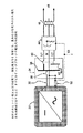
図12を参照すると、本発明のフレーム式AC PVビルディングブロック200は、好ましくは、完全に封入された、完全統合型光起電力システムである。全てのDC回路及び構成要素は、パッケージに封入される。追加として、エネルギを収集し、相互接続分岐回路へのルートを定めることに関連するAC回路、アレイ相互接続、及びサージ保護も、封入され、AC PVビルディングブロックからの出力を開始させる基準として機能する適合AC電源にシステムが接続されるまで、消費者及び設置者にとって全く安全なものとなる。
【0075】
同じ構造は、ディスパッチ、データ取得、及びAC PVビルディングブロック状態に関する通信も収容する。「パワーバー」又は「パワーレール」の「相互接続バー」又は「相互接続レール」のフレーム部材又はレール部材のいずれかは、仕上げアタッチメント又は相互接続アタッチメントにより、終点として終端処理することができる。この組立体は、トラック照明に類似しており、設置及び保守が同様に簡単である。「パワーバー」又は「相互接続バー」のフレーム部材は、多数のAC PVビルディングブロックを完全な組立体にする相互接続を提供するために、同様の封入構造(表示なし)を介して相互接続することができる。フレーム式の実施形態は、光起電モジュール12と、相互接続バー202と、シール204と、ACバスリンク/接続/ジャンパ206と、接地ネジ208(必要な場合)と、接合ネジ210(必要な場合)と、サージ保護付きACバス212と、通信ケーブル又は光ファイバリンク214と、インバータ216(様々なサイズにしてよい)と、パワーバー218と、クラッディング220(耐日光性)と、オプションの絶縁材料222とを備える。
【0076】
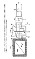
図13は、AC PVビルディングブロックの屋根マウント式実施形態300を例示している。「パワーバー」の本体は、構造的な全体性を維持し、全ての必須要素を収容すると同時に、対応に対する最大の露出が可能となるように準備される。「インバータ」は、「パワーバー」内部に収容され、「光起電モジュール」によって生成された電力のDC−AC変換と、光起電システムの相互接続を規定する様々な規格で求められる電圧範囲、出力電流制限、及び非孤立化といった必要な相互接続保護及び動作制限とを提供する。
【0077】
ACバスは、「パワーバー」が全体として交換可能要素であるか、或いはインバータを交換可能構成要素にすることが意図されているかに応じて、様々な取り付け方法でインバータに取り付けられる。いくつかのバージョンが開発中である「挿入接点」は、熱膨張/収縮の柔軟性を提供するように設計された「モジュール/インバータジャンパ」を介して、光起電モジュールとの電気的接続を形成する。「光起電モジュール」を「パワーバー」に接続する形態は、半田付け、ボルト締め、及び溶接によって全ての接続を恒久的にするためのものとなる。
【0078】
これにより、「パワーバー」の現場での交換は、実行可能な修復方法となる。「パワーバー」及び「相互接続バー」は、耐候性金属、或いは耐候性及び耐日光性の非伝導体材料により構成されるクラッド材料を使用して構築してもよい。いずれの設計においても、二重絶縁設計が提供され、この場合、危険な電圧が人間に接触可能となる前に、二つの障壁を突破する必要がある状態となる。金属又は伝導性クラッディングが使用される時、「パワーバー」及び「相互接続バー」は、図13において接地ネジ及び又は接合ネジによって表示するように、安全のための接地及び接合維持の方法を提供する必要がある。追加的な構成要素は、モジュール接点302(挿入接点及び又はインバータジャンパを備えてもよい)と、オプションのモジュールマウント304とである。
【0079】
「ACバスリンク」は、電気的接続及びジャンパを提供し、好ましくは30年以上の電気的連続性を維持し、熱膨張及び収縮を補う十分な柔軟性を有する。「ACバスリンク」は、光起電設備の特色である様々な屋外環境に関連する腐食に対する耐性を有する必要がある。「ACバスリンク」は、更に、通信リンクを含んでもよい。「通信ケーブル」は、伝導体又は光ファイバ材料にしてよい。次のAC PVビルディングブロック、或いは建物の相互接続とのリンクは、「ACバスリンク」の一部にしてもよく、或いは別個のリンクにしてもよい。
【0080】
「相互接続バー」は、システムのレイアウトに応じて、使用してもよく、使用しなくてもよい。使用する時、その主要な目的は、AC PVビルディングブロックの列の一方の側からの電力及び通信を、他方の側に転送すること、或いは、全てのAC電力を接続の中心点に運ぶヘッダを提供することである。「パワーバー」又は「パワーレール」の「相互接続バー」又は「相互接続レール」のフレーム部材又はレール部材のいずれかは、仕上げアタッチメント又は相互接続アタッチメントにより、終点として終端処理することができる。「パワーバー」又は「相互接続バー」のフレーム部材は、多数のAC PVビルディングブロックを完全な組立体にする相互接続を提供するために、同様の封入構造を介して相互接続することができる。
【0081】
図14は、光起電モジュールが窓ガラス又はその他の壁の構造及び材料に置き換わる窓壁用途400での代表的な仕組みを例示している。光起電モジュールは、不透明又は半透明にしてよい。AC PVビルディングブロックは、家屋及び高層建築物の従来のムリオンに置き換わる建物一体化部材を提供する。AC PVビルディングブロックによって提供されるムリオンは、光起電システムのAC伝導体のルートを定めるコンジットの役割を果たすことについてリストアップ及び承認されることになる。リストアップされたムリオンは、システムの配線及び機器の接地に関するリストアップ済み又は承認済みの方法を使用するための規則及び規格の要件を保証する。
【0082】
「パワーバー」の本体は、建物の規則で求められる構造部材を提供しつつ、電力の変換と安全性とに関する全ての必須要素を収容すると同時に、太陽への露出を最大にするように準備される。「インバータ」は、「パワーバー」内部に収容され、「光起電モジュール」によって生成された電力のDC−AC変換と、光起電システムの相互接続を規定する様々な規格で求められる電圧範囲、出力電流制限、及び非孤立化といった必要な相互接続保護及び動作制限とを提供する。ACバスは、「パワーバー」が全体として交換可能要素であるか、或いはインバータを交換可能構成要素にすることが意図されているかに応じて、様々な取り付け方法でインバータに取り付けられる。
【0083】
いくつかのバージョンが開発中である「挿入接点」は、熱膨張/収縮の柔軟性を提供するように設計された「モジュール/インバータジャンパ」を介して、光起電モジュールとの電気的接続を形成する。「光起電モジュール」を「パワーバー」に接続する形態は、半田付け、ボルト締め、及び溶接によって全ての接続を恒久的にするためのものとなる。これにより、「パワーバー」の現場での交換は、実行可能な修復方法となる。「パワーバー」及び「相互接続バー」は、耐候性金属、或いは耐候性及び耐日光性の非伝導体材料により構成されるクラッド材料を使用して構築してもよい。いずれの設計においても、二重絶縁設計が提供され、この場合、危険な電圧が人間に接触可能となる前に、二つの障壁を突破する必要がある状態となる。金属又は伝導性クラッディングが使用される時、「パワーバー」及び「相互接続バー」は、図15において接地ネジ及び又は接合ネジによって表示するように、安全のための接地及び接合維持の方法を提供する必要がある。
【0084】
「相互接続バー」は、システムのレイアウトに応じて、使用してもよく、使用しなくてもよい。使用する時、その主要な目的は、AC PVビルディングブロックの列の一方の側からの電力及び通信を、他方の側に転送すること、或いは、全てのAC電力を接続の中心点に運ぶヘッダを提供することである。「パワーバー」又は「相互接続バー」のフレーム部材のいずれかは、仕上げアタッチメント又は相互接続アタッチメントにより、終点として終端処理することができる。「パワーバー」又は「相互接続バー」のフレーム部材は、多数のAC PVビルディングブロックを完全な組立体にする相互接続を提供するために、同様の封入構造を介して相互接続することができる。
【0085】
図15は、別のマウントのオプションに関するAC PVビルディングブロックの「レールマウント」バージョン500を例示している。「パワーレール」502及び「相互接続レール」504の全ての要素は、「パワーバー」及び「相互接続バー」と同様である。主要な違いは、レールが光起電モジュール又はラミネートの裏面に取り付けられることであり、これにより、小さな屋根面積又は効率の低い光起電モジュール技術に関して、光起電モジュールの優れたパッキングが可能となる。「レールマウント」バージョンは、電柱での直接的な接地又は広告板での接地及びその他、或いは、駐車場の日よけ構造、会議場、及びその他に関して、屋根マウントが実用的でないために使用し得るような自立式「地面マウント接地」に適合化し得るラック上でのAC PVビルディングブロックのマウントに関するオプションを提供する。
【0086】
「パワーレール」又は「相互接続レール」のレール部材のいずれかは、仕上げアタッチメント又は相互接続アタッチメントにより、終点として終端処理することができる。「パワーレール」又は「相互接続レール」のレール部材は、多数のAC PVビルディングブロックを完全な組立体にする相互接続を提供するために、同様の封入構造を介して相互接続することができる。
【0087】
図16は、上面破断図において、この構造をパワーバー218及び相互接続バー202と共に表示しており、この構造はAC PVビルディングブロック又は負荷への最終接続に接続する開口部203を伴っている。
【0088】
フレーム部材の一実施形態は、特に薄膜アモルファスPVシートに関して、PVパネル接合部でガラス間接合を随意的に作り出すガラスのハウジングを形成することである。フレーム部材には、内部に収容する物品の移動を防止するために、発泡体材料を充填してもよい。現在市販される標準的なPVパネルでは、電気接点の位置の修正のみが必要となる。現在のパネルにおいて、こうした接点は、パネルのエッジから遠く離れて配置されているが、本発明において、こうした接点は、好ましくは、パネルのエッジ近く、或いはパネルのエッジ上に存在する。
【0089】
まとめると、本発明は、以下を含む形式において有益である:
1.フレーム式又は非フレーム式にできる結晶又は薄膜光−電気エネルギ変換技術及び構築方法のいずれかを利用し、部材又はレール部材及び関連電気接続及びリンクの相互接続に対するアクセスを提供し、適合する相互接続回路にAC電力のみを提供する任意の形状である、完全統合型光起電のモジュール。
【0090】
2.全ての内部DC接続と、AC変換(インバータ)と、AC電力バスと、通信リンクと、サージ保護と、オプションの過電流保護と、次のモジュールフレーム又はレール或いはAC負荷及び回路への接続に関する最終ジャンクションボックスに対する必要な全てのリンクとを収容及び包含することにも使用される部材を形成するために、伝導性、絶縁性、又は積層部材のいずれかにより構築された、「パワーバー」又は「パワーレール」のフレーム部材又はレール部材。
【0091】
3.インバータが封入されるかどうかに関係なく、DC−ACインバータの全ての集合的な電気回路と、プリント基板と、構成要素とを収容するように設計された、「パワーバー」又は「パワーレール」のフレーム部材又はレール部材。
【0092】
4.ACエネルギのみを、適合するAC電源に接続された時のみ生成する完全な光起電アレイに、光起電モジュールを電気的及び機械的に相互接続する形で、「相互接続バー」又は「相互接続レール」及び又は「パワーバー」又は「パワーレール」に結合された、「パワーバー」又は「パワーレール」のフレーム部材又はレール部材。
【0093】
5.DC−ACインバータに関連する電力電子機器に関する必要なヒートシンク及び熱管理を提供するように設計された、「パワーバー」又は「パワーレール」のフレーム部材又はレール部材。
【0094】
6.インバータ又はサージ保護の故障の際に、非破壊的に光起電モジュールから取り外される、或いは開放して修復が可能となるように設計された、「パワーバー」又は「パワーレール」のフレーム部材又はレール部材。
【0095】
7.インバータ又はサージ保護の故障の際に、修復のための選択肢として、非破壊的に光起電モジュールから取り外されるように設計された、「パワーバー」又は「パワーレール」のフレーム部材又はレール部材。
【0096】
8.光起電モジュールのエッジに取り付けることが可能で、同時に、挿入接点、ジャンパ、又は専用リンクを通じた、モジュールからインバータへのDC電気接続を提供する、「パワーバー」又は「パワーレール」の「相互接続バー」又は「相互接続レール」。
【0097】
9.光起電モジュール又は光起電アレイを備えるモジュールの集合のための機械的マウント部材として使用され得るオプションのクランプ、フィッティング、マウンティング、スナップ、及びその他を伴う、「パワーバー」又は「パワーレール」の「相互接続バー」又は「相互接続レール」のフレーム部材又はレール部材。
【0098】
10.「パワーバー」又は「パワーレール」のフレーム部材又はレール部材を光起電モジュールの両側で接着又はシーリングするオプションの接着剤及び又はシーリング材料を包含又は使用し得る、「パワーバー」又は「パワーレール」の「相互接続バー」又は「相互接続レール」のフレーム部材又はレール部材。
【0099】
11.電気AC電力バス、通信ケーブル又は光学リンク、ACサージ保護デバイス、及びDC−ACを共に収容し、同時に、専用ACバスリンクを介して、安価かつ堅牢なACバス相互接続を提供する電気コンジットとしてリストアップ、認証、又は承認され得る形で構築される、「パワーバー」又は「パワーレール」の「相互接続バー」又は「相互接続レール」のフレーム部材又はレール部材。
【0100】
12.積層金属部を使用して構築する時、障害のある条件又は電圧を加えられた条件の下で、接触し得る人間への電気ショックのリスクを排除するために必要な接地及び接合を提供する、「パワーバー」又は「パワーレール」の「相互接続バー」又は「相互接続レール」のフレーム部材又はレール部材。
【0101】
13.金属クラッディングが構造に使用されている場合でも「二重絶縁」電気デバイスとしての資格を有し、更に非接地光起電システムを運用するための要件を満たす様な形で、適切な絶縁材料を使用して構築されるように設計された、「パワーバー」又は「パワーレール」の「相互接続バー」又は「相互接続レール」のフレーム部材又はレール部材。
【0102】
14.傾斜屋根及び平屋根用の屋根上マウントシステム、建物正面マウントシステム、建物一体化システム、窓壁システム、天窓、建築システム、及びポールマウントシステムを一部として含む、あらゆるタイプの光起電設備に対応する、「パワーバー」又は「パワーレール」のフレーム部材又はレール部材、及び様々な設計、構造、及び形状の適合する「相互接続バー」。
【0103】
15.光起電モジュールに取り付けられ、雨又は吹き付ける水による水分の侵入から光起電モジュールのエッジを保護するシールを容易にするように設計された、「パワーバー」又は「パワーレール」の「相互接続バー」又は「相互接続レール」のフレーム部材又はレール部材。
【0104】
16.光起電モジュールに取り付けられ、雨と、吹き付ける水と、海岸の空気によって運ばれる塩或いは工場用地近くで見られる硫黄又は腐食性の煙といった汚染物のような腐食性材料とからDC相互接続点及び材料を保護するシールを容易にするように設計された、「パワーバー」又は「パワーレール」の「相互接続バー」又は「相互接続レール」のフレーム部材又はレール部材。
【0105】
17.光起電モジュールのフレーム化を完成させるように設計され、「パワーバー」又は「パワーレール」と同様の形で構築された、「相互接続バー」又は「相互接続レール」のフレーム部材又はレール部材。ACビルディングブロックの再構成のため、或いは屋根の修復を容易にするために、非破壊的に取り外すことも可能である。
【0106】
18.AC PVビルディングブロックの列の間で、必要なAC電力及び通信の相互接続を提供する、「相互接続バー」又は「相互接続レール」のフレーム部材又はレール部材。
【0107】
19.モジュール全体で、モジュールの次の列に対する電力及び通信リンクを提供する、或いは最終相互接続部材又はボックスの配置に関するAC電力の集合を可能にする、「相互接続バー」又は「相互接続レール」のフレーム部材又はレール部材。
【0108】
20.「パワーバー」又は「パワーレール」の「相互接続バー」又は「相互接続レール」のフレーム部材又はレール部材のいずれかは、仕上げアタッチメント又は相互接続アタッチメントにより、終点として終端処理することができる。
【0109】
21.「パワーバー」又は「パワーレール」の「相互接続バー」又は「相互接続レール」のフレーム部材又はレール部材は、多数のAC PVビルディングブロックを完全な組立体にする相互接続を提供するために、同様の封入構造を介して相互接続することができる。
【0110】
以上、好適な実施形態を特に参照して本発明を詳細に説明してきたが、他の実施形態も同様の結果を達成し得る。本発明の変更及び変形は、当業者にとって自明であり、付記した特許請求の範囲にはこうした全ての変形及び等価物が包含される。上で参照した全ての参考文献、出願、特許、及び刊行物の開示内容全体は、出典を明記することにより本願明細書の一部とする。
【図面の簡単な説明】
【0111】
【図1】代表的な従来のグリッド接続光起電システムのブロック図
【図2】本発明による、代表的なグリッド接続光起電システムのブロック図
【図3】一相接地出力が使用される住宅用途での本発明の使用に関する相互接続図
【図4】一相非接地出力が使用される住宅用途での本発明の使用に関する相互接続図
【図5】スタンドアロンインバータからの単相が、一相接地サービスを介して、住宅に全ての電力を提供する、住宅用途での本発明の使用に関する相互接続図
【図6】一対のスタンドアロンインバータからの二相が、センタータップサービスを介して、住宅に電力を提供する、住宅用途での本発明の使用に関する相互接続図
【図7】スタンドアロンインバータからの電力が、一相接地サービスを介して、住宅に電力を提供する、住宅ハイブリッド用途での本発明の使用に関する相互接続図
【図8】多数のインバータが、三相配電の単一相にそれぞれ接続される、商業又は住宅用途での本発明の使用に関する相互接続図
【図9】単一の三相インバータが三相配電に接続される、商業又は住宅用途での本発明の使用に関する相互接続図
【図10】本発明のAC PVビルディングブロックが、小さなステップダウントランスを介して、配電線に直接結合される、ポールマウント式公共電気用途での本発明の使用に関する相互接続図
【図11】本発明のAC PVビルディングブロックが、広告板サービスに直接結合される、広告板マウント式公共電気双方向用途での本発明の使用に関する相互接続図
【図12】本発明のフレーム式AC PVビルディングブロックの斜視図
【図13】本発明の屋根マウント式AC PVビルディングブロックの側面破断図
【図14】本発明の窓壁式AC PVビルディングブロックの側面破断図
【図15】屋上、地面マウント式、又はポールマウント式用途のための本発明のレールマウント式AC PVビルディングブロックの斜視図
【図16】「パワーバー」及び「相互接続バー」を利用した代表的なAC PVビルディングブロックレイアウトの上面破断図【Technical field】
[0001]
The present invention relates to modularization of photovoltaic systems. Description of Related Application This application claims the benefit of the application of US Provisional Application No. 60 / 335,668 “Development of New AC Photovoltaic Building Blocks” filed October 25, 2001, The specification is made a part of this specification by specifying the source. Government Rights The government has rights to the invention in accordance with Contract No. DE-AC04-94AL85000 awarded by the US Department of Energy. The present invention provides a fully integrated self-contained alternating current ("AC") photovoltaic ("PV") building block device and a method of forming a true plug and play device through photovoltaic applications. To do.
[Background]
[0002]
The following description refers to a large number of publications by author (s) and year of publication, and the particular publication is the most recent publication date and therefore cannot be considered prior art to the present invention. Please note that. In this specification, the descriptions of these publications are presented as a more complete background and should not be construed as an approval for the purpose of determining patentability that such publications are prior art. Absent.
[0003]
Today's photovoltaic systems typically comprise a single photovoltaic module or multiple modules connected by a combination of series or parallel circuits as a photovoltaic array. In the case of a single module system that generates AC output, the photovoltaic module is equipped with a fuse to protect the photovoltaic module when it can be back-fed from other sources (eg, public electricity or batteries). It is connected to an inverter or load through an integrated junction box. The photovoltaic modules used in such systems are configured with or without a frame. Frameless photovoltaic modules are commonly referred to as laminates. In conventional systems that utilize a large number of laminates or modules, the laminates or modules are interconnected via junction boxes or flying leads and external wiring that is rated for sun resistance and must be sized to carry the rated current. Connected. Some conventional photovoltaic system installations require that direct current (“DC”) and AC wiring be installed in a suitably sized fixed conduit.
[0004]
A typical method of interconnecting DC circuits in a conventional photovoltaic system is to connect the module circuit to a flying lead conductor by a J-box at the top of each photovoltaic module that provides a terminal block, and then Attach the flying lead wire to the connector. The J-box further accommodates series or “blocking” diodes that are often required by rules and standards for protecting modules, particularly when two modules are paralleled in a combiner box or inverter. Modules are often constructed with bypass diode (s) normally required in conventional photovoltaic applications.
[0005]
This mechanism is used to connect modules in series. The modules are connected in series until the total operating voltage falls within the optimal DC voltage window of the center or string inverter. This connection is usually made on a modular basis by connecting the connectors together or by connecting them to a distributed junction box. Some facilities leave insufficient space for the installer to make a reliable connection. A central inverter can typically handle multiple columns of photovoltaic modules, and multiple columns of photovoltaic modules are then placed in a string combiner or box before DC power is supplied to the inverter. Wired in parallel.
[0006]
FIG. 1 illustrates a typical conventional grid-connected photovoltaic system. An
[0007]
Next, the wiring 9 (which may be accompanied by a conduit) transfers power to the
[0008]
The AC PV building block of the present invention eliminates all DC wiring, fuse requirements, and the need for bypass or series diodes, J-boxes, and connections. All connections except the final AC connection become part of the integrated package of the present invention.
[0009]
FIG. 2 illustrates an exemplary grid-connected photovoltaic system according to the present invention. The AC PV
[0010]
Power is provided to AC disconnect, fuse, and
[0011]
The AC PV building block of the present invention can be (1) a public electricity grid, (2) a mini-grid that utilizes other sources of AC power, often referred to as hybrid systems, or (3) a remote residence, communications station, Any that provides AC power for emergency lighting and stand-alone power systems that typically use inverters to store AC power to off-grid loads such as multiple remote energy systems that require AC power It can be utilized by photovoltaic systems of size and / or shape.
[0012]
It is also possible to combine the present invention to form a complete photovoltaic energy system using single or multiple photovoltaic modules, where the power interconnection, conversion, protection and coupling is Can be generated within a listed or approved structure that is also used for mounting, mounting, and bonding of photovoltaic modules.
[0013]
The following US patents generally relate to the state of the art in photovoltaic systems: US Pat. No. 6,219,623 to Willis, US Pat. No. 6,285,572 to Onizuka, US Pat. No. 6 to Meyer. , 201,180, U.S. Patent No. 6,143,582 to Bu, U.S. Patent No. 6,111,189 to Garbison, U.S. Patent No. 6,046,400 to Drama, U.S. Patent No. 5, to Baron. 742,495, and US Pat. No. 5,702,963 to Bu.
[0014]
Pacific Solar manufactures Plug and Power and SunEmpower System using micro inverters. However, microinverters are separate components that are not physically attached to the photovoltaic panel. To be precise, the microinverter is electrically interconnected to the photovoltaic panel via a separate cable. Furthermore, all interconnections are via cables on both the DC and AC sides. The US Electrical Code (National Electrical Code®) and related regulations and standards still remain in the Pacific Solar Plug and Power / SunEmper design, with DC fuses, ground fault detection / breaking, DC disconnection, and DC side International grounding is required. In addition, the installation cost of the Plug and Power / SunEmpower design is increased by the required interconnection devices, the need for a separate inverter housing, and the housing required for the J-box and / or combiner.
[0015]
The Applied Power Corporation's SunSine (registered trademark) 300 product also uses microinverters. However, exposed cable wiring is utilized to connect each panel microinverter to the adjacent panel microinverter.
[0016]
The following references also relate to the latest technology in photovoltaic systems: Stevens, J., et al., “Development and testing of approaches to non-isolation in photovoltaic systems incorporated into public works” , SAND2000-1939, Sandia National Laboratories, Albuquerque, NM (Aug. 2000), IEEE Recommendations on Public Works Interfaces for Photovoltaic (PV) Systems, IEEE
DISCLOSURE OF THE INVENTION
[0017]
The present invention relates to a modular apparatus and method for AC photovoltaic power generation, comprising generating power in the form of a DC via a photovoltaic module and one or more power conversions attached to the module. And converting the direct current to alternating current and transporting power via a transfer unit, each unit comprising a single housing extending the length or width of the module, the housing receiving direct current from the module Contact means, one or more DC / AC inverters, and an AC bus. An AC bus link attached to the bus allows interconnection in parallel with other devices according to the present invention to form an AC photovoltaic array.
[0018]
Data may be communicated via a data communication link included in the housing. One or more interconnection units may be attached to the module and electrically connected to an AC bus leading to an external connection point for AC power to the electrical service panel. The housing provides physical modularity by utilizing an I-beam shape, a channel shape, or a T-beam shape. The housing may further comprise any or all of the following: a surge protector for one or more inverters and photovoltaic modules, a communication network for reporting status information, a communication network for dispatch or other selection criteria, Seals that provide weather resistance and thermal management means. The module may be frame-type, roof-mount-type, open-structure-mount-type, pole-mount-type, or window-wall-type. No external DC fuse or DC disconnect is required.
[0019]
The present invention further relates to an AC photovoltaic generation system comprising one or more modular AC photovoltaic generation devices as described above.
[0020]
The present invention further relates to a modular apparatus and method for generating an alternating photovoltaic voltage, comprising generating in the form of direct current, receiving direct current and one or more via a photovoltaic module. Converting to alternating current through a direct current alternating current inverter and transporting alternating current through one or more power transfer units attached to the module, each unit extending the length or width of the module A single housing is provided, the housing comprising contact means for transmitting direct current to one or more inverters, contact means for receiving alternating current from the one or more inverters, and an alternating current bus.
[0021]
The present invention further relates to a modular AC photovoltaic generator comprising a photovoltaic panel with an edge, a hollow structural member attached to the edge of the panel, and a DC / AC inverter module attached to the structural member. It is. The apparatus may further comprise an alternating current bus disposed within the hollow structural member and an interconnect means disposed within the hollow structural member for transferring direct current from the photovoltaic panel to the inverter module. .
[0022]
Objects, advantages, and novel features and further scope of applicability of the present invention will be set forth in part in the following detailed description, in conjunction with the accompanying drawings, and in part by considering the following: It will be apparent to those skilled in the art or may be learned by practice of the present invention. The objects and advantages of the invention may be realized and attained by means of the instrumentalities and combinations particularly pointed out in the appended claims.
BEST MODE FOR CARRYING OUT THE INVENTION
[0023]
The accompanying drawings, which are incorporated in and constitute a part of this specification, illustrate one or more embodiments of the invention and together with the description, serve to clarify the principles of the invention. This drawing is only for the purpose of illustrating one or more preferred embodiments of the invention and should not be construed as limiting the invention.
[0024]
The present invention is an integrated alternating current (“AC”) light that is a fully integrated photovoltaic component (accompanying power generation method), can be used as a photovoltaic power source, and has only an AC output. It relates to electromotive (“PV”) building blocks (hereinafter “AC PV building blocks”). The present invention combines, includes and integrates almost all electrical and mechanical elements of a photovoltaic system.
[0025]
The present invention eliminates any considerations regarding the DC voltage of today's photovoltaic systems by placing the DC element inside the AC PV building block structure. Within the same structure, the present invention allows the DC power generated by the photovoltaic module to be fully compatible with AC public electrical grids, minigrids, or small stand-alone and hybrid power systems, depending on application requirements. And a complementary inverter or generator can maintain a compatible reference voltage.
[0026]
AC PV building blocks provide AC electrical output only and supply only when connected to a compatible power source and load. The present invention uses crystalline silicon, polycrystalline silicon, thin film crystalline silicon, amorphous silicon on crystalline silicon, thin film amorphous silicon, thin film cadmium telluride, thin film copper indium diselenide and other elements. It is compatible with all known photovoltaic module technologies and photovoltaic module designs that use technology including variants and modules of crystalline gallium arsenide. Also suitable for certain concentrator modules that generally use lower concentrations.
[0027]
The present invention can be applied to numerous configurations with slight changes in the design of the internal DC-AC conversion device. Such a configuration can be grounded or ungrounded, depending on the requirements of the interconnection. The output can be single phase or three phase power depending on the requirements of the interconnection. The range of operation regarding voltage and frequency can be selected by the design of the DC-AC conversion device.
[0028]
The AC PV building block includes one-way or two-way communication for dispatching, data logging, or conveying the operating state or history of the AC PV building block. The communication can be performed on a separate communication cable (also included in the structure) or various power line carrier communication methods can be utilized. Communication is to units located near conventional communication lines (eg, telephone lines) or to units located near AC circuits / distribution panels inside buildings or other structures that utilize photovoltaic power. It can also be performed by wireless means such as Bluetooth, GHz band, ultra-wideband, radio frequency, or other means.
[0029]
AC PV building blocks have the ability to parallel (total) the output of multiple modules that provide countless benefits in relation to installation, orientation, modular technology, aging, breakage, and failure. A single module failure or breakage only reduces the equivalent of one AC PV building block in total output. Similarly, shadows from trees, chimneys, and vents will reduce output by the number of AC PV building blocks affected. Due to the nature of the output, it is possible to use a number of modular technologies, and aging or degradation of one module only affects its output, does not create problems with tracking the maximum output point of the entire system, or Does not reduce the operating window of the system to a level where a specific inverter can no longer function.
[0030]
The concept of AC PV building blocks is a fully integrated design or package that eliminates the following elements or problems associated with interconnecting conventional photovoltaic systems around the world. External or additional components and elements that are excluded by this design include, as part of:
1. DC wiring and related holders, cable trays, conduits, and others,
2. DC disconnect and associated housing,
3. DC fuse and associated holder and housing,
4). Any commercial type DC connector and DC overcurrent protection,
5. DC ground fault detection and protection circuit and device,
6). DC surge protection,
7). DC combiner box,
8). Individual DC junction box and connector block,
9. “Series or blocking diodes” associated with photovoltaic modules or arrays,
10. Most if not all photovoltaic module bypass diodes,
11. Inverter housing as required for inverters in conventional photovoltaic systems
12 AC wiring, except as required as part of a connection with a dedicated or diverted branch circuit for interconnection with an AC public electrical grid or hybrid microgrid, and
13. Conduit for DC wiring.
[0031]
Some of the conventional hardware used in today's photovoltaic system designs that are replaced by, or contained within, the present invention and its components include:
1. Wiring and connectors between photovoltaic modules,
2. DC-AC conversion (inverter)
3. Inverter housing
4). Hardware and frame for photovoltaic module mounting
5. Surge protection on AC circuit of photovoltaic module,
6). Conduit for DC wiring and some AC wiring,
7). Mechanical mounting hardware such as frames or rails, and
8). Numerous AC J-boxes.
[0032]
The reduced DC-AC conversion device (inverter) included as part of the AC PV building block is preferably an integral part of a replaceable element, hereinafter referred to as “power bar” or “power rail” The “power bar” or “power rail” also has an integrated connection with an AC bus bar to which multiple building blocks can be added. The “power bar” — “interconnect bar” and “power rail” — “interconnect rail” mechanical assemblies maintain the necessary electrical coupling, provide double insulation properties, and provide weather resistance. The DC-AC conversion device can also be replaced partially or entirely. Thus, the AC PV building block of the present invention can be a base unit on which any type of photovoltaic system can be built. The present invention uses a fully integrated mounting structure that serves as a mechanical assembly, DC connection to the photovoltaic module, electronic DC-AC conversion, surge protection, communication bus, and power distribution element.
[0033]
In an alternative embodiment, the microinverter can be mounted outside the power bar or power rail. This embodiment has certain advantages in that the inverter module can be easily replaced and can be easily cooled. The inverter module can be plugged into a power bar or power rail just as a 120V plug is plugged into an outlet (eg, using a prong). The inverter module can also be attached to the bottom of the power bar or power rail with an optional integrated rain guard fin for the power bar or power rail to reduce the possibility of rainwater damaging the inverter.
[0034]
Microinverters utilized in AC PV building blocks can have the following mechanical characteristics:
1. It can be completely encapsulated, partially encapsulated, or comprised of circuit boards and components that are not encapsulated.
[0035]
2. Contact tabs that can be directly attached to the AC bus can be included.
[0036]
3. Jumpers and contacts that complete the electrical connection with the photovoltaic module can be included.
[0037]
4). It can be an integrated unit, or it can be composed of a number of elements that are usually divided into a power switching section, a control section, a communication section, an interconnection section, and others.
[0038]
5. Various thermal management means can be used, such as heat pipes, fins, three-dimensional heat transfer, radiating devices, and heat conduction to nearby housings. A good insulator between the inverter and the frame is beryllium oxide because BeO becomes a relatively good heat conductor and electrical insulator.
[0039]
6). An electrical contact with a communication device or cable that originates in or extends through the housing can be provided.
[0040]
7). Can be designed to be a permanent part of a power bar or power rail.
[0041]
8). It can be designed to be a replaceable part of a power bar or power rail.
[0042]
9. Can be designed to be water resistant.
[0043]
10. Can be designed to be corrosion resistant.
[0044]
11. Can be designed to be weather resistant.
[0045]
The microinverter can further have the following electrical or electrical control characteristics.
[0046]
1. The use of short-lived components such as field capacitors can be minimized.
[0047]
2. Inductive energy storage can be replaced by electrostatic energy storage.
[0048]
3. It can be designed to convert the power of the entire photovoltaic module or a portion of the photovoltaic module.
[0049]
4). To eliminate components, it can be designed to use features such as high proximity to the photovoltaic module.
[0050]
5. It can be designed to use features such as high proximity to the photovoltaic module as an alternative to methods such as temperature algorithms to provide maximum power point tracking.
[0051]
6). Can be designed to include surge protection.
[0052]
7). It can be designed to substitute for functions such as overcurrent protection or disconnection.
[0053]
8). It can be designed to interface or provide data logging, request side management, status reporting, and other communications.
[0054]
9. It can be designed to provide an AC output only when the AC node exhibits voltage, frequency, and other necessary characteristics.
[0055]
10. It can be designed to trade off performance parameters such as module utilization and inverter efficiency.
[0056]
11. Can be designed to meet existing interconnection guidelines and requirements.
[0057]
12 It can be designed to operate in parallel with a similar inverter or other inverters connected in parallel or in the service panel.
[0058]
13. It can be designed to limit or wrap around power transfer when the temperature reaches a preset limit. Capacitors that do not use electrolysis with high reliability and long life are selected because of the potential temperature rise within the frame of the present invention.
[0059]
AC PV building block assemblies can be constructed in such a way that all types and shapes of photovoltaic modules are available. Other advantages of the present invention include inverter housing, junction block, junction box, individual connectors, surge protection, communication circuits and cables, conduits, photovoltaic module mounting options, photovoltaic module application options, and photovoltaic This includes replacing, substituting, or integrating elements related to the balance of the system in a separate photovoltaic system, including most wiring in the array as part.
[0060]
The final assembly can be fitted together or mechanically constructed using screws, bolts, nuts, and others, resulting in rooftop, building-integrated, pole-mounted, Or, it is an assembly of environmental conservation type (weather resistance, moisture resistance, heat resistance, sunlight resistance) suitable for photovoltaic applications with an open structure. The final assembly is mechanically robust and attaches with a wide range of mounting or tightening options and then attaches with the necessary screws and fasteners to comply with mechanical and electrical rules or standards.
[0061]
This AC PV building block paves the way for easy practitioner, designer, and installer certification requirements, and excellently guarantees installation and building integration in accordance with photovoltaic technology regulations. The final assembly can be constructed to meet double insulation requirements, as used in some European countries, or as is done in many appliances today. AC PV building block DC systems can be ungrounded or grounded (though some of the advantages on the DC side may be lost in a grounded configuration) like today's conventional photovoltaic systems It is. As an advantage of the non-grounded configuration, relatively sensitive inverter electronics can be protected from stray currents caused by nearby lightning strikes.
[0062]
3 through 11 show block diagrams of the most common electrical configurations to which the AC PV building block of the present invention can be applied. The output voltage and frequency of the AC PV building block may vary depending on national standards and the connections described in each.
[0063]
FIG. 3 shows the most common application for interconnection in residential applications that may use the AC
[0064]
When used on a "power bar", "interconnect bar", "power rail", or "interconnect rail", all exposed
[0065]
FIG. 4 illustrates another general application for interconnection in residential applications that may use the AC
[0066]
FIG. 5 illustrates a typical application in residential applications that may use AC PV building blocks with other stand-alone power sources. This configuration (usually used in small cabins) draws single phase power from a grounded source that can be supplemented by AC PV building blocks. High power circuits such as electric clothes dryers or electric ovens are usually wired to receive 240V, but this option is not available in this configuration. The AC PV building block provides power at 120V or any other supply single phase voltage with one terminal ungrounded. This configuration includes an
[0067]
FIG. 6 illustrates a typical application in a residential application that may use an AC PV building block with other stand-alone power supplies (usually inverters). This configuration (usually used in small cabins) draws single phase power from a grounded source that can be supplemented by AC PV building blocks. This AC PV building block provides power at 120V or any other supply single phase ground voltage or two phase voltage with both terminals ungrounded.
[0068]
FIG. 7 illustrates the most common application in residential applications where the public electrical system is classified as a minigrid or
[0069]
FIG. 8 illustrates interconnections in a typical application in residential and commercial systems that can use AC PV building blocks. Worldwide, most commercial and industrial facilities are wired with three-phase power. The voltage varies depending on power requirements and country. Most three-phase household circuits are outside the United States (varies by country). This AC PV building block provides any line-to-neutral or line-to-line voltage (often using a suitable transformer for voltage matching). The output of the AC PV building block may or may not be grounded.
[0070]
FIG. 8 shows a case where the line-neutral line voltage is sufficiently low and direct connection is possible. At higher voltages, matching
[0071]
FIG. 9 illustrates the interconnections for general applications in residential and commercial systems that can use three-phase AC PV building blocks. This AC PV building block provides three-phase power at any line-to-neutral or line-to-line voltage (using a suitable transformer for voltage matching). The output of the AC PV building block may or may not be grounded. FIG. 9 shows a case where the line-neutral line voltage is sufficiently low and direct connection is possible. At higher voltages, a matching transformer on a dedicated branch circuit is required. Additional components are a three-phase AC
[0072]
FIG. 10 shows a typical application in public electrical applications where AC PV building block interconnections are made in utility poles via small step-down transformers. A beneficial application occurs when distributed generation that roughly matches the load profile provides line support over long distance or stress transmission lines. This AC PV building block provides power at a single phase or three phase voltage with both terminals ungrounded or one terminal grounded. FIG. 10 shows an ungrounded configuration. Additional components are a pole mounted
[0073]
FIG. 11 illustrates an application that lights the billboard at night but provides a convenient structure for collecting photovoltaic power. Billboards already connected to the grid direct photovoltaic power to public electricity through the AC PV building block during the daytime, and at night, the billboard is powered by the power supplied by the public electricity grid. This is the connection method when it can be lit. Additional components are
[0074]
Referring to FIG. 12, the framed AC
[0075]
The same structure also accommodates communications regarding dispatch, data acquisition, and AC PV building block status. Either the “power bar” or “power rail” “interconnect bar” or “interconnect rail” frame member or rail member can be terminated as an end point by a finish attachment or interconnect attachment. This assembly is similar to track lighting and is equally simple to install and maintain. The “power bar” or “interconnect bar” frame members interconnect through similar encapsulating structures (not shown) to provide an interconnect that completes multiple AC PV building blocks. be able to. The framed embodiment includes a
[0076]
FIG. 13 illustrates an AC PV building block
[0077]
The AC bus is attached to the inverter in various ways depending on whether the "power bar" is a replaceable element as a whole or the inverter is intended to be a replaceable component. Several versions of the “insertion contacts” in development provide electrical connections to photovoltaic modules via “module / inverter jumpers” designed to provide thermal expansion / contraction flexibility. Form. The form of connecting the “photovoltaic module” to the “power bar” is to make all connections permanent by soldering, bolting and welding.
[0078]
This makes the “power bar” on-site replacement a viable repair method. “Power bars” and “interconnect bars” may be constructed using a weathering metal or a cladding material composed of a weathering and sunlight resistant non-conductive material. In either design, a double insulation design is provided, in which case the two barriers need to be broken before dangerous voltages can be contacted by humans. When metal or conductive cladding is used, the “power bar” and “interconnect bar” indicate how to ground and bond for safety, as indicated by the ground screw and / or bonding screw in FIG. Need to provide. Additional components are a module contact 302 (which may include an insertion contact and / or an inverter jumper) and an
[0079]
The “AC bus link” provides electrical connections and jumpers, preferably has sufficient flexibility to maintain electrical continuity for over 30 years and compensate for thermal expansion and contraction. The “AC bus link” needs to be resistant to corrosion associated with various outdoor environments that are characteristic of photovoltaic facilities. The “AC bus link” may further include a communication link. The “communication cable” may be a conductor or an optical fiber material. The next AC PV building block or link to the building interconnect may be part of an “AC bus link” or may be a separate link.
[0080]
The “interconnect bar” may or may not be used depending on the layout of the system. In use, its primary purpose is to transfer power and communication from one side of the AC PV building block row to the other side, or a header that carries all AC power to the central point of the connection. Is to provide. Either the “power bar” or “power rail” “interconnect bar” or “interconnect rail” frame member or rail member can be terminated as an end point by a finish attachment or interconnect attachment. The “power bar” or “interconnect bar” frame members can be interconnected through similar enclosing structures to provide an interconnect that completes multiple AC PV building blocks.
[0081]
FIG. 14 illustrates an exemplary arrangement in a
[0082]
The body of the “power bar” is prepared to maximize the sun exposure while accommodating all the essential elements of power conversion and safety while providing the structural members required by building regulations. The The “inverter” is housed inside the “power bar” and is a voltage range required by various standards that define the DC-AC conversion of the power generated by the “photovoltaic module” and the interconnection of the photovoltaic system. Provide necessary interconnect protection and operational limitations such as output current limiting and non-isolation. The AC bus is attached to the inverter in various ways depending on whether the "power bar" is a replaceable element as a whole or the inverter is intended to be a replaceable component.
[0083]
Several versions of the “insertion contacts” in development provide electrical connections to photovoltaic modules via “module / inverter jumpers” designed to provide thermal expansion / contraction flexibility. Form. The form of connecting the “photovoltaic module” to the “power bar” is to make all connections permanent by soldering, bolting and welding. This makes the “power bar” on-site replacement a viable repair method. “Power bars” and “interconnect bars” may be constructed using a weathering metal or a cladding material composed of a weathering and sunlight resistant non-conductive material. In either design, a double insulation design is provided, in which case the two barriers need to be broken before dangerous voltages can be contacted by humans. When metal or conductive cladding is used, the “power bar” and “interconnect bar” indicate how to ground and bond for safety, as indicated by the ground screw and / or bonding screw in FIG. Need to provide.
[0084]
The “interconnect bar” may or may not be used depending on the layout of the system. In use, its primary purpose is to transfer power and communication from one side of the AC PV building block row to the other, or a header that carries all AC power to the central point of the connection. Is to provide. Either the “power bar” or “interconnect bar” frame members can be terminated as end points by finishing attachments or interconnect attachments. The “power bar” or “interconnect bar” frame members can be interconnected through similar enclosing structures to provide an interconnect that completes multiple AC PV building blocks.
[0085]
FIG. 15 illustrates a “rail mount”
[0086]
Either the "power rail" or "interconnect rail" rail members can be terminated as an end point by a finish attachment or an interconnect attachment. Rail members of a “power rail” or “interconnect rail” can be interconnected through similar enclosing structures to provide an interconnect that completes multiple AC PV building blocks.
[0087]
FIG. 16 shows this structure with a
[0088]
One embodiment of the frame member is to form a glass housing that optionally creates a glass-to-glass bond at the PV panel joint, particularly for thin film amorphous PV sheets. The frame member may be filled with a foam material in order to prevent movement of an article accommodated therein. With standard PV panels currently on the market, it is only necessary to correct the position of the electrical contacts. In current panels, such contacts are located far away from the edge of the panel, but in the present invention such contacts are preferably present near or on the edge of the panel.
[0089]
In summary, the present invention is beneficial in a form that includes:
1. Utilizing either crystalline or thin-film photo-electric energy conversion techniques and construction methods, which can be framed or unframed, provide access to and compatible with member or rail members and associated electrical and link interconnections A fully integrated photovoltaic module in any shape that provides only AC power to the circuit.
[0090]
2. Final on all internal DC connections, AC conversion (inverter), AC power bus, communication link, surge protection, optional overcurrent protection and connection to the next module frame or rail or AC load and circuit A “power bar” or “built by either conductive, insulative, or laminated members to form a member that is also used to house and contain all the necessary links to the junction box Power rail "frame member or rail member.
[0091]
3. A “power bar” or “power rail” designed to accommodate all collective electrical circuits, printed circuit boards, and components of a DC-AC inverter, regardless of whether the inverter is encapsulated Frame member or rail member.
[0092]
4). An “interconnect bar” or “interconnect” in which the photovoltaic modules are electrically and mechanically interconnected into a complete photovoltaic array that only generates AC energy when connected to a suitable AC power source. A frame member or rail member of a “power bar” or “power rail” coupled to a “connection rail” and / or “power bar” or “power rail”.
[0093]
5. A “power bar” or “power rail” frame member or rail member designed to provide the necessary heat sink and thermal management for the power electronics associated with the DC-AC inverter.
[0094]
6). "Power bar" or "power rail" frame members designed to be removed non-destructively from the photovoltaic module or opened for repair in the event of an inverter or surge protection failure Rail member.
[0095]
7). A “power bar” or “power rail” frame member or rail member designed to be non-destructively removed from the photovoltaic module as a repair option in the event of an inverter or surge protection failure.
[0096]
8). A "power bar" or "power rail""mutual" that can be attached to the edge of a photovoltaic module and at the same time provides a DC electrical connection from the module to the inverter through an insertion contact, jumper or dedicated link "Connection bar" or "interconnection rail".
[0097]
9. A “power bar” or “power rail” with optional clamps, fittings, mountings, snaps, and others that can be used as mechanical mounting members for a collection of photovoltaic modules or modules with photovoltaic arrays Frame member or rail member of “interconnect bar” or “interconnect rail”.
[0098]
10. A “power bar” or “power rail” that may include or use an optional adhesive and / or sealing material to bond or seal the frame member or rail member of the “power bar” or “power rail” on both sides of the photovoltaic module "Interconnect bar" or "interconnect rail" frame member or rail member.
[0099]
11. Listed as an electrical conduit that houses an electrical AC power bus, communication cable or optical link, AC surge protection device, and DC-AC at the same time and provides an inexpensive and robust AC bus interconnect via a dedicated AC bus link A “power bar” or “power rail” “interconnect bar” or “interconnect rail” frame or rail member constructed in a manner that can be up, certified, or approved.
[0100]
12 When constructed using laminated metal parts, it provides the grounding and bonding necessary to eliminate the risk of electrical shock to humans that may be touched under faulty or voltage-enforced conditions; Frame member or rail member of “interconnect bar” or “interconnect rail” of “power bar” or “power rail”.
[0101]
13. Appropriate insulating materials that qualify as “double-insulated” electrical devices, even when metal cladding is used in the structure, and that meet the requirements for operating ungrounded photovoltaic systems A “power bar” or “power rail” “interconnect bar” or “interconnect rail” frame member or rail member designed to be constructed using
[0102]
14 Compatible with all types of photovoltaic equipment, including on-roof mounting systems for sloped and flat roofs, building front mounting systems, building integration systems, window wall systems, skylights, building systems, and pole mounting systems The “power bar” or “power rail” frame member or rail member, and the “interconnect bar” of various designs, structures, and shapes.
[0103]
15. "Power bar" or "power rail""interconnect" designed to facilitate sealing that is attached to the photovoltaic module and protects the edges of the photovoltaic module from the ingress of moisture by rain or blowing water Frame member or rail member of "bar" or "interconnect rail".
[0104]
16. DC interconnection points from rain, spray water, and corrosive materials such as salt carried by coastal air or contaminants such as sulfur or corrosive smoke found near the factory site, attached to photovoltaic modules And a “power bar” or “power rail” “interconnect bar” or “interconnect rail” frame member or rail member designed to facilitate sealing to protect the material.
[0105]
17. Frame member or rail member of "interconnect bar" or "interconnect rail" designed to complete the framing of photovoltaic modules and constructed in the same manner as "power bar" or "power rail" . It can also be removed non-destructively for the reconstruction of AC building blocks or to facilitate the repair of the roof.
[0106]
18. A frame member or rail member of an “interconnect bar” or “interconnect rail” that provides the necessary AC power and communication interconnection between rows of AC PV building blocks.
[0107]
19. An "interconnect bar" or "interconnect rail" frame that provides power and communication links for the next row of modules throughout the module, or allows collection of AC power for final interconnect member or box placement Member or rail member.
[0108]
20. Either the “power bar” or “power rail” “interconnect bar” or “interconnect rail” frame member or rail member can be terminated as an end point by a finish attachment or interconnect attachment.
[0109]
21. The “power bar” or “power rail” “interconnect bar” or “interconnect rail” frame member or rail member provides a complete assembly of a number of AC PV building blocks. Interconnects can be made through similar encapsulation structures.
[0110]
Although the present invention has been described in detail above with particular reference to preferred embodiments, other embodiments may achieve similar results. Modifications and variations of the present invention will be apparent to those skilled in the art, and the appended claims encompass all such variations and equivalents. The entire disclosure of all references, applications, patents, and publications referred to above are hereby incorporated by reference.
[Brief description of the drawings]
[0111]
FIG. 1 is a block diagram of a typical conventional grid-connected photovoltaic system.
FIG. 2 is a block diagram of an exemplary grid-connected photovoltaic system according to the present invention.
FIG. 3 is an interconnection diagram for use of the present invention in residential applications where a single phase ground output is used
FIG. 4 is an interconnection diagram for use of the present invention in residential applications where a single phase ungrounded output is used.
FIG. 5 is an interconnection diagram for the use of the present invention in a residential application, where a single phase from a stand-alone inverter provides all power to the home via a single phase ground service.
FIG. 6 is an interconnection diagram for the use of the present invention in residential applications where two phases from a pair of standalone inverters provide power to the home via a center tap service.
FIG. 7 is an interconnection diagram for the use of the present invention in a residential hybrid application where power from a stand-alone inverter provides power to the home via a single phase ground service.
FIG. 8 is an interconnection diagram for the use of the present invention in commercial or residential applications, where multiple inverters are each connected to a single phase of a three-phase power distribution.
FIG. 9 is an interconnection diagram for the use of the present invention in commercial or residential applications, where a single three-phase inverter is connected to a three-phase power distribution.
FIG. 10 is an interconnection diagram for use of the present invention in a pole mounted utility utility where the AC PV building block of the present invention is coupled directly to a distribution line via a small step-down transformer.
FIG. 11 is an interconnection diagram for the use of the present invention in billboard mounted public electricity interactive applications where the AC PV building block of the present invention is directly coupled to billboard services.
FIG. 12 is a perspective view of the frame AC PV building block of the present invention.
FIG. 13 is a side cutaway view of the roof mounted AC PV building block of the present invention.
FIG. 14 is a side cutaway view of the window wall AC PV building block of the present invention.
FIG. 15 is a perspective view of a rail mounted AC PV building block of the present invention for rooftop, ground mounted or pole mounted applications.
FIG. 16 is a top cutaway view of a typical AC PV building block layout utilizing “power bars” and “interconnect bars”.
Claims (22)
直流の形態で電力を発生させる光起電モジュールと
前記モジュールに取り付けられた一つ以上の電力変換及び転送ユニットと、
を備え、
各前記ユニットが、前記モジュールの長さ又は幅に亘って延びる単一のハウジングを備え、
前記ハウジングが、
前記モジュールから直流を受領するための接点手段と、
一つ以上の直流交流インバータと、
交流バスと、
を備える装置。A modular AC photovoltaic generator,
A photovoltaic module for generating power in the form of a direct current and one or more power conversion and transfer units attached to the module;
With
Each unit comprises a single housing extending over the length or width of the module;
The housing comprises:
Contact means for receiving direct current from the module;
One or more DC-AC inverters;
AC bus and
A device comprising:
光起電モジュールを介して、直流の形態で電力を発生させるステップと、
モジュールに取り付けられた一つ以上の電力変換及び転送ユニットを介して、直流を交流に変換して電力を輸送するステップと、を備え、
各ユニットが、モジュールの長さ又は幅に亘って延びる単一のハウジングを備え、
前記ハウジングが、
モジュールから直流を受領するための接点手段と、
一つ以上の直流交流インバータと、
交流バスと、を備える
方法。An AC photovoltaic power generation method,
Generating power in the form of direct current via the photovoltaic module;
Transporting power by converting direct current to alternating current via one or more power conversion and transfer units attached to the module, and
Each unit comprises a single housing that extends the length or width of the module;
The housing comprises:
Contact means for receiving direct current from the module;
One or more DC-AC inverters;
An AC bus.
直流の形態で電力を発生させる光起電モジュールと、
前記光起電モジュールから直流を受領する一つ以上の直流交流インバータと、
前記モジュールに取り付けられた一つ以上の電力転送ユニットと、
を備え、
各前記ユニットが、前記モジュールの長さ又は幅に亘って延びる単一のハウジングを備え、
前記ハウジングが、
前記一つ以上のインバータから交流を受領するための接点手段と、
交流バスと、を備える、
装置。A modular AC photovoltaic generator,
A photovoltaic module that generates power in the form of direct current;
One or more DC AC inverters receiving DC from the photovoltaic module;
One or more power transfer units attached to the module;
With
Each unit comprises a single housing extending over the length or width of the module;
The housing comprises:
Contact means for receiving alternating current from the one or more inverters;
An AC bus,
apparatus.
光起電モジュールを介して、直流の形態で電力を発生させるステップと、
直流を受領し、一つ以上の直流交流インバータを介して交流に変換するステップと、
モジュールに取り付けられた一つ以上の電力転送ユニットを介して交流電流を輸送するステップと、
を備え、
各ユニットが、モジュールの長さ又は幅に亘って延びる単一のハウジングを備え、
前記ハウジングが、
一つ以上のインバータへ直流を送給する接点手段、及び一つ以上のインバータから交流を受領するための接点手段と、
交流バスと、
を備える、
方法。A method for generating an alternating photovoltaic power, comprising:
Generating power in the form of direct current via the photovoltaic module;
Receiving direct current and converting it to alternating current through one or more direct current alternating current inverters;
Transporting alternating current through one or more power transfer units attached to the module;
With
Each unit comprises a single housing that extends the length or width of the module,
The housing
Contact means for delivering direct current to one or more inverters, and contact means for receiving alternating current from one or more inverters;
AC bus,
Comprising
Method.
エッジを有する光起電パネルと、
前記パネルの前記エッジに取り付けられた中空構造部材と、
前記構造部材に取り付けられた直流交流インバータモジュールと、
を備える装置。A modular AC photovoltaic generator,
A photovoltaic panel having an edge;
A hollow structural member attached to the edge of the panel;
A DC / AC inverter module attached to the structural member;
A device comprising:
前記中空構造部材の内部に配置され、前記光起電パネルから前記インバータモジュールへ直流を転送する相互接続手段と、
を更に備える、請求項21記載の装置。An AC bus disposed inside the hollow structural member;
An interconnection means disposed within the hollow structural member for transferring direct current from the photovoltaic panel to the inverter module;
The apparatus of claim 21, further comprising:
Applications Claiming Priority (2)
| Application Number | Priority Date | Filing Date | Title |
|---|---|---|---|
| US33566801P | 2001-10-25 | 2001-10-25 | |
| PCT/US2002/034368 WO2003036688A2 (en) | 2001-10-25 | 2002-10-25 | Alternating current photovoltaic building block |
Publications (2)
| Publication Number | Publication Date |
|---|---|
| JP2005507169A true JP2005507169A (en) | 2005-03-10 |
| JP2005507169A5 JP2005507169A5 (en) | 2005-12-22 |
Family
ID=23312763
Family Applications (1)
| Application Number | Title | Priority Date | Filing Date |
|---|---|---|---|
| JP2003539079A Pending JP2005507169A (en) | 2001-10-25 | 2002-10-25 | AC Photovoltaic Building Block |
Country Status (5)
| Country | Link |
|---|---|
| US (1) | US6750391B2 (en) |
| EP (1) | EP1442473A4 (en) |
| JP (1) | JP2005507169A (en) |
| AU (1) | AU2002348084A1 (en) |
| WO (1) | WO2003036688A2 (en) |
Cited By (7)
| Publication number | Priority date | Publication date | Assignee | Title |
|---|---|---|---|---|
| JP2009538110A (en) * | 2006-05-18 | 2009-10-29 | グリッドポイント,インコーポレーテッド | Modular energy control system |
| KR101086467B1 (en) | 2010-11-19 | 2011-11-25 | (주)하나정밀 | Solar-cell moudle integrated a building outer frame |
| WO2012106003A1 (en) * | 2011-02-01 | 2012-08-09 | Solaria Corporation | Solar module window shade apparatus and method |
| JP2013078256A (en) * | 2011-09-29 | 2013-04-25 | Taida Electronic Ind Co Ltd | Renewable energy power generation system and power generation method |
| JP2013537025A (en) * | 2010-08-31 | 2013-09-26 | エスエムエー ソーラー テクノロジー アーゲー | Inverter with AC interface for AC module connection |
| JP2015522235A (en) * | 2012-07-03 | 2015-08-03 | サンレゴ エネルジ システムレリ サナイ ヴェ ティジャーレット アノニム シルケティ | AC solar panel system |
| KR102641715B1 (en) * | 2023-06-23 | 2024-02-28 | (주)그린파워 | Rail Integrated Induction Power Supply System |
Families Citing this family (246)
| Publication number | Priority date | Publication date | Assignee | Title |
|---|---|---|---|---|
| US20170212399A1 (en) * | 2013-06-16 | 2017-07-27 | Tang System | W5RS: Anlinx & Milinx & Zilinx for Green Energy Smart Window |
| JP2003052185A (en) * | 2001-05-30 | 2003-02-21 | Canon Inc | Power converter, and photovoltaic element module using the same and power generator |
| JP2003158282A (en) * | 2001-08-30 | 2003-05-30 | Canon Inc | Solar photovoltaic power-generation system |
| US7297866B2 (en) * | 2004-03-15 | 2007-11-20 | Sunpower Corporation | Ventilated photovoltaic module frame |
| DE102004053942A1 (en) * | 2004-11-09 | 2006-05-11 | Solarwatt Solar-Systeme Gmbh | Connection unit for photovoltaic solar modules |
| DE102004057042A1 (en) * | 2004-11-25 | 2006-06-08 | Bbg Gmbh & Co. Kg | Wall cladding panel for a building exterior wall with a solar generator |
| US20060124167A1 (en) * | 2004-12-15 | 2006-06-15 | Xuejun Fan | Thermal-efficient power converter enclosure for solar panels |
| AT501542B1 (en) * | 2004-12-16 | 2009-03-15 | Fronius Int Gmbh | METHOD FOR DETECTING THE LOAD OF AN ISLE CHANGE AND ISOLATOR INVERTER |
| WO2006094128A2 (en) * | 2005-03-01 | 2006-09-08 | Beacon Power Corporation | Methods and systems for intentionally isolating distributed power generation sources |
| CN100347928C (en) * | 2005-03-15 | 2007-11-07 | 清华大学 | Photovoltaic parallel network device having reactive and harmonic compensation function |
| US7738228B2 (en) * | 2005-04-07 | 2010-06-15 | Pv Powered, Inc. | Inverter thermal protection |
| US20060250828A1 (en) * | 2005-04-07 | 2006-11-09 | Bill Taylor | Inverter power electronics design |
| US20060250783A1 (en) * | 2005-04-07 | 2006-11-09 | Taylor Bill W F | Inverter operation modes |
| US7397653B2 (en) * | 2005-04-07 | 2008-07-08 | Pv Powered, Inc. | Inverter design |
| US20070086215A1 (en) * | 2005-04-07 | 2007-04-19 | Bill Taylor | Inverter operation modes |
| US7502241B2 (en) * | 2005-04-07 | 2009-03-10 | Pv Powered, Inc. | Inverter startup algorithm |
| US20060227472A1 (en) * | 2005-04-07 | 2006-10-12 | William Taylor | Inverter ground fault circuit |
| US7432618B2 (en) * | 2005-04-07 | 2008-10-07 | Pv Powered, Inc. | Inverter anti-islanding method |
| US7274975B2 (en) | 2005-06-06 | 2007-09-25 | Gridpoint, Inc. | Optimized energy management system |
| US20070102038A1 (en) * | 2005-11-11 | 2007-05-10 | Christian Kirschning | Holding Element For Photovoltaic Modules |
| US20070119496A1 (en) * | 2005-11-30 | 2007-05-31 | Massachusetts Institute Of Technology | Photovoltaic cell |
| US10693415B2 (en) | 2007-12-05 | 2020-06-23 | Solaredge Technologies Ltd. | Testing of a photovoltaic panel |
| US11881814B2 (en) | 2005-12-05 | 2024-01-23 | Solaredge Technologies Ltd. | Testing of a photovoltaic panel |
| ITRM20050635A1 (en) * | 2005-12-19 | 2007-06-20 | Eric S R L | PHOTOVOLTAIC DEVICE AND PLANT WITH SELECTIVE CONCENTRATION. |
| US20070171888A1 (en) * | 2006-01-20 | 2007-07-26 | Benjamin Joseph Adams | Method and apparatus for establishing a wireless communications network solar powered access points |
| EP2008343B1 (en) * | 2006-03-09 | 2017-08-09 | SunPower Corporation, Systems | Photovoltaic module mounting clip with integral grounding |
| US20080137327A1 (en) * | 2006-09-22 | 2008-06-12 | Michael Gerard Hodulik | Grid-tied solar™ streetlighting |
| US7906870B2 (en) * | 2006-10-13 | 2011-03-15 | Pv Powered, Inc. | System and method for anti-islanding, such as anti-islanding for a grid-connected photovoltaic inverter |
| GB2442994A (en) * | 2006-10-20 | 2008-04-23 | Wind Save Ltd | Solar panel with AC power converter |
| US20080115911A1 (en) * | 2006-11-22 | 2008-05-22 | Tyco Electronics Corporation | Heat dissipation system for solarlok photovoltaic interconnection system |
| US9431828B2 (en) * | 2006-11-27 | 2016-08-30 | Xslent Energy Technologies | Multi-source, multi-load systems with a power extractor |
| US8963369B2 (en) | 2007-12-04 | 2015-02-24 | Solaredge Technologies Ltd. | Distributed power harvesting systems using DC power sources |
| US9130401B2 (en) | 2006-12-06 | 2015-09-08 | Solaredge Technologies Ltd. | Distributed power harvesting systems using DC power sources |
| US11309832B2 (en) | 2006-12-06 | 2022-04-19 | Solaredge Technologies Ltd. | Distributed power harvesting systems using DC power sources |
| US11569659B2 (en) | 2006-12-06 | 2023-01-31 | Solaredge Technologies Ltd. | Distributed power harvesting systems using DC power sources |
| US9088178B2 (en) | 2006-12-06 | 2015-07-21 | Solaredge Technologies Ltd | Distributed power harvesting systems using DC power sources |
| US8013472B2 (en) | 2006-12-06 | 2011-09-06 | Solaredge, Ltd. | Method for distributed power harvesting using DC power sources |
| US8319471B2 (en) | 2006-12-06 | 2012-11-27 | Solaredge, Ltd. | Battery power delivery module |
| US11735910B2 (en) | 2006-12-06 | 2023-08-22 | Solaredge Technologies Ltd. | Distributed power system using direct current power sources |
| US11687112B2 (en) | 2006-12-06 | 2023-06-27 | Solaredge Technologies Ltd. | Distributed power harvesting systems using DC power sources |
| US8384243B2 (en) | 2007-12-04 | 2013-02-26 | Solaredge Technologies Ltd. | Distributed power harvesting systems using DC power sources |
| US11296650B2 (en) | 2006-12-06 | 2022-04-05 | Solaredge Technologies Ltd. | System and method for protection during inverter shutdown in distributed power installations |
| US8947194B2 (en) | 2009-05-26 | 2015-02-03 | Solaredge Technologies Ltd. | Theft detection and prevention in a power generation system |
| US8473250B2 (en) | 2006-12-06 | 2013-06-25 | Solaredge, Ltd. | Monitoring of distributed power harvesting systems using DC power sources |
| US9112379B2 (en) | 2006-12-06 | 2015-08-18 | Solaredge Technologies Ltd. | Pairing of components in a direct current distributed power generation system |
| US8816535B2 (en) | 2007-10-10 | 2014-08-26 | Solaredge Technologies, Ltd. | System and method for protection during inverter shutdown in distributed power installations |
| US8618692B2 (en) | 2007-12-04 | 2013-12-31 | Solaredge Technologies Ltd. | Distributed power system using direct current power sources |
| US11888387B2 (en) | 2006-12-06 | 2024-01-30 | Solaredge Technologies Ltd. | Safety mechanisms, wake up and shutdown methods in distributed power installations |
| US11855231B2 (en) | 2006-12-06 | 2023-12-26 | Solaredge Technologies Ltd. | Distributed power harvesting systems using DC power sources |
| US8319483B2 (en) | 2007-08-06 | 2012-11-27 | Solaredge Technologies Ltd. | Digital average input current control in power converter |
| US11728768B2 (en) | 2006-12-06 | 2023-08-15 | Solaredge Technologies Ltd. | Pairing of components in a direct current distributed power generation system |
| US7994657B2 (en) * | 2006-12-22 | 2011-08-09 | Solarbridge Technologies, Inc. | Modular system for unattended energy generation and storage |
| WO2008086114A2 (en) | 2007-01-03 | 2008-07-17 | Gridpoint, Inc. | Utility console for controlling energy resources |
| EP1965483B1 (en) * | 2007-02-27 | 2015-07-08 | SMA Solar Technology AG | Circuit for connecting an energy generation unit to the power grid |
| WO2008108909A1 (en) * | 2007-03-07 | 2008-09-12 | Greenrey, Inc. | Multi-function frame and integrated mounting system for photovoltaic power generating laminates |
| US8300439B2 (en) * | 2007-03-07 | 2012-10-30 | Greenray Inc. | Data acquisition apparatus and methodology for self-diagnosing of AC modules |
| US7772716B2 (en) * | 2007-03-27 | 2010-08-10 | Newdoll Enterprises Llc | Distributed maximum power point tracking system, structure and process |
| US9196770B2 (en) | 2007-03-27 | 2015-11-24 | Newdoll Enterprises Llc | Pole-mounted power generation systems, structures and processes |
| WO2011019936A1 (en) | 2009-08-14 | 2011-02-17 | Newdoll Enterprises Llc | Enhanced solar panels, liquid delivery systems and associated processes for solar energy systems |
| US20090000654A1 (en) | 2007-05-17 | 2009-01-01 | Larankelo, Inc. | Distributed inverter and intelligent gateway |
| US20080283118A1 (en) * | 2007-05-17 | 2008-11-20 | Larankelo, Inc. | Photovoltaic ac inverter mount and interconnect |
| US20080309217A1 (en) * | 2007-05-18 | 2008-12-18 | Mulder Carlijn L | Organic light emitting devices |
| US9172296B2 (en) * | 2007-05-23 | 2015-10-27 | Advanced Energy Industries, Inc. | Common mode filter system and method for a solar power inverter |
| US8203069B2 (en) * | 2007-08-03 | 2012-06-19 | Advanced Energy Industries, Inc | System, method, and apparatus for coupling photovoltaic arrays |
| US8294296B2 (en) * | 2007-08-03 | 2012-10-23 | Advanced Energy Industries, Inc. | System, method, and apparatus for remotely coupling photovoltaic arrays |
| US8097980B2 (en) * | 2007-09-24 | 2012-01-17 | Sunlight Photonics Inc. | Distributed solar power plant and a method of its connection to the existing power grid |
| JP2009099971A (en) * | 2007-09-28 | 2009-05-07 | Enphase Energy Inc | General interface for photovoltaic module |
| US7755916B2 (en) | 2007-10-11 | 2010-07-13 | Solarbridge Technologies, Inc. | Methods for minimizing double-frequency ripple power in single-phase power conditioners |
| EP3324505B1 (en) | 2007-10-15 | 2023-06-07 | Ampt, Llc | Systems for highly efficient solar power |
| US7919953B2 (en) | 2007-10-23 | 2011-04-05 | Ampt, Llc | Solar power capacitor alternative switch circuitry system for enhanced capacitor life |
| FR2923653B1 (en) * | 2007-11-08 | 2009-11-27 | Harald Hauf | OPERATING METHOD AND DEVICE FOR CONTROLLING AN ENERGY PLANT WITH PHOTOVOLTAIC MODULES. |
| US8294451B2 (en) * | 2007-12-03 | 2012-10-23 | Texas Instruments Incorporated | Smart sensors for solar panels |
| US9291696B2 (en) | 2007-12-05 | 2016-03-22 | Solaredge Technologies Ltd. | Photovoltaic system power tracking method |
| US11264947B2 (en) | 2007-12-05 | 2022-03-01 | Solaredge Technologies Ltd. | Testing of a photovoltaic panel |
| CN101933209B (en) | 2007-12-05 | 2015-10-21 | 太阳能安吉有限公司 | Release mechanism in distributed electrical power apparatus, to wake up and method for closing |
| EP2232690B1 (en) | 2007-12-05 | 2016-08-31 | Solaredge Technologies Ltd. | Parallel connected inverters |
| US8049523B2 (en) | 2007-12-05 | 2011-11-01 | Solaredge Technologies Ltd. | Current sensing on a MOSFET |
| WO2009086238A2 (en) * | 2007-12-21 | 2009-07-09 | E. I. Du Pont De Nemours And Company | Photovoltaic array and methods |
| US20100269891A1 (en) * | 2007-12-21 | 2010-10-28 | E.I. Du Pont De Nemours And Company | Modular structural members for assembly of photovoltaic arrays |
| US20110048504A1 (en) * | 2007-12-21 | 2011-03-03 | E.I. Du Pont De Nemours And Company | Photovoltaic array, framework, and methods of installation and use |
| BRPI0906511A2 (en) * | 2008-01-09 | 2017-06-13 | Petra Solar Inc | photovoltaic, power conversion and connector mounts, and docking station. |
| WO2009108408A2 (en) * | 2008-01-14 | 2009-09-03 | Massachusetts Institute Of Technology | Hybrid solar concentrator |
| US8933320B2 (en) * | 2008-01-18 | 2015-01-13 | Tenksolar, Inc. | Redundant electrical architecture for photovoltaic modules |
| US8212139B2 (en) | 2008-01-18 | 2012-07-03 | Tenksolar, Inc. | Thin-film photovoltaic module |
| US8748727B2 (en) * | 2008-01-18 | 2014-06-10 | Tenksolar, Inc. | Flat-plate photovoltaic module |
| US8418688B2 (en) * | 2008-02-08 | 2013-04-16 | Greenray Inc. | Assembly and method for mounting solar panels to structural surfaces |
| US20090302680A1 (en) * | 2008-02-15 | 2009-12-10 | Kent Kernahan | Distributed photovoltaic power generation system |
| WO2009118682A2 (en) | 2008-03-24 | 2009-10-01 | Solaredge Technolgies Ltd. | Zero current switching |
| US8383943B2 (en) * | 2008-03-28 | 2013-02-26 | Greenray, Inc. | Electrical cable harness and assembly for transmitting AC electrical power |
| US7719864B2 (en) * | 2008-04-02 | 2010-05-18 | Array Converter, Inc. | Pulse amplitude modulated current converter |
| WO2009132158A1 (en) | 2008-04-22 | 2009-10-29 | Array Converter, Inc. | High voltage array converter |
| US8289183B1 (en) | 2008-04-25 | 2012-10-16 | Texas Instruments Incorporated | System and method for solar panel array analysis |
| WO2009136358A1 (en) | 2008-05-05 | 2009-11-12 | Solaredge Technologies Ltd. | Direct current power combiner |
| US8053662B2 (en) * | 2008-05-09 | 2011-11-08 | Kasra Khazeni | Solar energy collection devices |
| US20090277495A1 (en) * | 2008-05-11 | 2009-11-12 | Mihai Talaba | Concentrated pv solar power stack system |
| ES2345750R (en) * | 2008-05-12 | 2010-10-13 | Ingeteam Energy, S.A. | ELECTRICAL CIRCUIT FOR PROTECTION OF PHOTOVOLTAIC SYSTEMS. |
| US20090283129A1 (en) * | 2008-05-14 | 2009-11-19 | National Semiconductor Corporation | System and method for an array of intelligent inverters |
| US9077206B2 (en) | 2008-05-14 | 2015-07-07 | National Semiconductor Corporation | Method and system for activating and deactivating an energy generating system |
| US7991511B2 (en) * | 2008-05-14 | 2011-08-02 | National Semiconductor Corporation | Method and system for selecting between centralized and distributed maximum power point tracking in an energy generating system |
| US8279644B2 (en) * | 2008-05-14 | 2012-10-02 | National Semiconductor Corporation | Method and system for providing maximum power point tracking in an energy generating system |
| US7969133B2 (en) * | 2008-05-14 | 2011-06-28 | National Semiconductor Corporation | Method and system for providing local converters to provide maximum power point tracking in an energy generating system |
| US8139382B2 (en) * | 2008-05-14 | 2012-03-20 | National Semiconductor Corporation | System and method for integrating local maximum power point tracking into an energy generating system having centralized maximum power point tracking |
| US7962249B1 (en) * | 2008-05-14 | 2011-06-14 | National Semiconductor Corporation | Method and system for providing central control in an energy generating system |
| US8023266B2 (en) * | 2008-05-20 | 2011-09-20 | Greenray Inc. | AC photovoltaic module and inverter assembly |
| GB0809235D0 (en) * | 2008-05-21 | 2008-06-25 | Poweroasis Ltd | Supervisory system controller for use with a renewable energy powered radio telecommunications site |
| US20090308426A1 (en) * | 2008-06-11 | 2009-12-17 | Kent Kernahan | Method and apparatus for installing, testing, monitoring and activating power generation equipment |
| US20090314335A1 (en) * | 2008-06-20 | 2009-12-24 | Mcclintock Meredith | Integral photovoltaic unit |
| US20090315336A1 (en) * | 2008-06-23 | 2009-12-24 | Hudson Worthington Harr | Renewable energy generation system |
| DE202008010312U1 (en) * | 2008-07-31 | 2008-10-02 | Phoenix Solar Ag | Photovoltaic system and generator junction box in a photovoltaic system |
| AU2008359997A1 (en) * | 2008-08-01 | 2010-02-04 | Petra Solar Inc. | System and method for utility pole distributed solar power generation |
| US20100043868A1 (en) * | 2008-08-06 | 2010-02-25 | David Sun | System and method for integrated solar power generator |
| US7619200B1 (en) * | 2008-08-10 | 2009-11-17 | Advanced Energy Industries, Inc. | Device system and method for coupling multiple photovoltaic arrays |
| US8461508B2 (en) | 2008-08-10 | 2013-06-11 | Advanced Energy Industries, Inc. | Device, system, and method for sectioning and coupling multiple photovoltaic strings |
| US8184372B1 (en) | 2008-09-04 | 2012-05-22 | Bingwu Gu | Low numerical aperture (low-NA) solar lighting system |
| US8378656B2 (en) * | 2008-09-19 | 2013-02-19 | General Electric Company | Quasi-AC, photovoltaic module for unfolder photovoltaic inverter |
| US20100071747A1 (en) * | 2008-09-23 | 2010-03-25 | Joe Brescia | Method of Operating Building Integrated Photovoltaic Conversion System |
| WO2010036811A1 (en) * | 2008-09-24 | 2010-04-01 | Jason Allen Oliver | Device, system and method for directly generating alternating current electricity from photovoltaic cells |
| US20110210611A1 (en) * | 2008-10-10 | 2011-09-01 | Ampt, Llc | Novel Solar Power Circuits |
| US20100126087A1 (en) * | 2008-11-13 | 2010-05-27 | Joe Brescia | Plank Based Photovoltaic Conversion System |
| US20100122723A1 (en) * | 2008-11-14 | 2010-05-20 | Arkadiusz Rudy Sadkowski | Photovoltaic Power for Communications Networks |
| US10153383B2 (en) * | 2008-11-21 | 2018-12-11 | National Semiconductor Corporation | Solar string power point optimization |
| KR101020730B1 (en) * | 2008-11-24 | 2011-03-09 | 엘지이노텍 주식회사 | Module Apparatus of Solar cell |
| US8362644B2 (en) * | 2008-12-02 | 2013-01-29 | Advanced Energy Industries, Inc. | Device, system, and method for managing an application of power from photovoltaic arrays |
| US9059603B2 (en) * | 2008-12-11 | 2015-06-16 | Sunline Jamaica Limited | Solar powered electrical energy generating device |
| WO2010078303A2 (en) * | 2008-12-29 | 2010-07-08 | Atonometrics, Inc. | Electrical safety shutoff system and devices for photovoltaic modules |
| US20100139749A1 (en) * | 2009-01-22 | 2010-06-10 | Covalent Solar, Inc. | Solar concentrators and materials for use therein |
| US20100191489A1 (en) * | 2009-01-28 | 2010-07-29 | Uqm Technologies, Inc. | Distributed Generation Power System |
| EP2219276B1 (en) * | 2009-02-11 | 2015-12-02 | SMA Solar Technology AG | Photovoltaic assembly for three-phase feeding into an electric energy supply network |
| CA2655007C (en) | 2009-02-20 | 2017-06-27 | Queen's University At Kingston | Photovoltaic cell inverter |
| WO2010114995A1 (en) * | 2009-04-01 | 2010-10-07 | Nextronex Energy Systems, Llc | A grid tie solar system and a method |
| US8435056B2 (en) * | 2009-04-16 | 2013-05-07 | Enphase Energy, Inc. | Apparatus for coupling power generated by a photovoltaic module to an output |
| WO2010121211A2 (en) * | 2009-04-17 | 2010-10-21 | National Semiconductor Corporation | System and method for over-voltage protection of a photovoltaic system with distributed maximum power point tracking |
| WO2010120315A1 (en) | 2009-04-17 | 2010-10-21 | Ampt, Llc | Methods and apparatus for adaptive operation of solar power systems |
| WO2010121181A2 (en) * | 2009-04-17 | 2010-10-21 | National Semiconductor Corporation | System and method for over-voltage protection in a photovoltaic system |
| US20100288327A1 (en) * | 2009-05-13 | 2010-11-18 | National Semiconductor Corporation | System and method for over-Voltage protection of a photovoltaic string with distributed maximum power point tracking |
| US8217534B2 (en) * | 2009-05-20 | 2012-07-10 | General Electric Company | Power generator distributed inverter |
| EP2911263A3 (en) | 2009-06-15 | 2015-10-14 | Tenksolar, Inc. | Illumination agnostic solar panel |
| KR20120038965A (en) * | 2009-06-15 | 2012-04-24 | 여호수아 피슐러 | Electrical grid solar energy harvesting system |
| US10873186B2 (en) | 2009-06-15 | 2020-12-22 | Yehoshua Fishler | Electrical grid solar energy harvesting system |
| FR2947099B1 (en) * | 2009-06-17 | 2013-11-15 | Cynegy Holdings France | PHOTOVOLTAIC TILE FOR ROOF |
| US8919053B2 (en) | 2009-07-02 | 2014-12-30 | Zep Solar, Llc | Leveling foot apparatus, system, and method for photovoltaic arrays |
| CN102549873B (en) * | 2009-07-16 | 2015-11-11 | 美国通控集团公司 | Intelligence expandable type power converter |
| US20110017256A1 (en) * | 2009-07-22 | 2011-01-27 | Osiris Isis Kether Stevens | Mountable thin film solar array system |
| US8279642B2 (en) | 2009-07-31 | 2012-10-02 | Solarbridge Technologies, Inc. | Apparatus for converting direct current to alternating current using an active filter to reduce double-frequency ripple power of bus waveform |
| US20160065127A1 (en) | 2009-08-14 | 2016-03-03 | Newdoll Enterprises Llc | Enhanced solar panels, liquid delivery systems and associated processes for solar energy systems |
| US9200818B2 (en) | 2009-08-14 | 2015-12-01 | Newdoll Enterprises Llc | Enhanced solar panels, liquid delivery systems and associated processes for solar energy systems |
| US20110050218A1 (en) * | 2009-08-28 | 2011-03-03 | Lohss Kurt L | non-contact magnetic current sensing and distribution system for determining individual power readings from a plurality of power sources |
| US8482156B2 (en) * | 2009-09-09 | 2013-07-09 | Array Power, Inc. | Three phase power generation from a plurality of direct current sources |
| US8207637B2 (en) * | 2009-10-09 | 2012-06-26 | Solarbridge Technologies, Inc. | System and apparatus for interconnecting an array of power generating assemblies |
| US8462518B2 (en) * | 2009-10-12 | 2013-06-11 | Solarbridge Technologies, Inc. | Power inverter docking system for photovoltaic modules |
| US20100139742A1 (en) * | 2009-10-12 | 2010-06-10 | Wayman Elizabeth N | Photovoltaic Module Assembly With Integrated Junctions |
| US20110084646A1 (en) * | 2009-10-14 | 2011-04-14 | National Semiconductor Corporation | Off-grid led street lighting system with multiple panel-storage matching |
| US20110088743A1 (en) * | 2009-10-15 | 2011-04-21 | Yuhao Luo | Method to manage a photovoltaic system |
| WO2011049985A1 (en) | 2009-10-19 | 2011-04-28 | Ampt, Llc | Novel solar panel string converter topology |
| US7990743B2 (en) * | 2009-10-20 | 2011-08-02 | General Electric Company | System and method for decreasing solar collector system losses |
| US8421400B1 (en) | 2009-10-30 | 2013-04-16 | National Semiconductor Corporation | Solar-powered battery charger and related system and method |
| US20110139213A1 (en) * | 2009-12-11 | 2011-06-16 | Du Pont Apollo Limited | Photovoltaic system and boost converter thereof |
| US8824178B1 (en) | 2009-12-31 | 2014-09-02 | Solarbridge Technologies, Inc. | Parallel power converter topology |
| ITRM20100008A1 (en) * | 2010-01-13 | 2011-07-14 | Solsonica S P A | PHOTOVOLTAIC MODULE WITH FIRE PROTECTION. |
| US9806445B2 (en) | 2010-01-25 | 2017-10-31 | Enphase Energy, Inc. | Method and apparatus for interconnecting distributed power sources |
| JP5737660B2 (en) | 2010-01-25 | 2015-06-17 | エンフェイズ エナジー インコーポレイテッド | Method and apparatus for interconnecting distributed power sources |
| US8502129B2 (en) * | 2010-02-16 | 2013-08-06 | Western Gas And Electric, Inc. | Integrated remotely controlled photovoltaic system |
| US8829330B2 (en) | 2010-02-23 | 2014-09-09 | Tenksolar, Inc. | Highly efficient solar arrays |
| US9773933B2 (en) | 2010-02-23 | 2017-09-26 | Tenksolar, Inc. | Space and energy efficient photovoltaic array |
| US8390977B2 (en) * | 2010-02-26 | 2013-03-05 | Advanced Energy Industries, Inc | Solar power inverters, including solar power inverters having surge protective devices, and associated methods |
| CN103119728A (en) * | 2010-04-26 | 2013-05-22 | 托徳·罗伯茨 | Solar array configurations |
| DE102010023084A1 (en) * | 2010-06-08 | 2011-08-11 | Yamaichi Electronics Deutschland GmbH, 81829 | Junction box, solar panel and method of generating a three-phase current |
| DE102010023212A1 (en) * | 2010-06-09 | 2011-12-15 | Schletter Gmbh | Support profile of a series of PV modules |
| US9299861B2 (en) | 2010-06-15 | 2016-03-29 | Tenksolar, Inc. | Cell-to-grid redundandt photovoltaic system |
| US20110314751A1 (en) * | 2010-06-29 | 2011-12-29 | Roger Jette | Solar panel mounting rack system |
| US8717720B2 (en) | 2010-07-20 | 2014-05-06 | Siemens Industry, Inc. | Systems and methods for providing arc fault and/or ground fault protection for distributed generation sources |
| KR101642152B1 (en) * | 2010-08-20 | 2016-07-22 | 엘지전자 주식회사 | Solar cell module |
| USD666974S1 (en) | 2010-09-24 | 2012-09-11 | Solarbridge Technologies, Inc. | Y-junction interconnect module |
| WO2012043155A1 (en) * | 2010-09-27 | 2012-04-05 | 三洋電機株式会社 | Outer frame of solar cell module and solar cell module |
| US8279649B2 (en) | 2010-10-11 | 2012-10-02 | Solarbridge Technologies, Inc. | Apparatus and method for controlling a power inverter |
| US8503200B2 (en) | 2010-10-11 | 2013-08-06 | Solarbridge Technologies, Inc. | Quadrature-corrected feedforward control apparatus and method for DC-AC power conversion |
| US9160408B2 (en) | 2010-10-11 | 2015-10-13 | Sunpower Corporation | System and method for establishing communication with an array of inverters |
| DE202010014775U1 (en) * | 2010-10-29 | 2011-02-10 | Sma Solar Technology Ag | Window or door of a building with integrated electronics |
| US10673229B2 (en) | 2010-11-09 | 2020-06-02 | Solaredge Technologies Ltd. | Arc detection and prevention in a power generation system |
| US10230310B2 (en) | 2016-04-05 | 2019-03-12 | Solaredge Technologies Ltd | Safety switch for photovoltaic systems |
| GB2485527B (en) | 2010-11-09 | 2012-12-19 | Solaredge Technologies Ltd | Arc detection and prevention in a power generation system |
| US10673222B2 (en) | 2010-11-09 | 2020-06-02 | Solaredge Technologies Ltd. | Arc detection and prevention in a power generation system |
| US9118213B2 (en) | 2010-11-24 | 2015-08-25 | Kohler Co. | Portal for harvesting energy from distributed electrical power sources |
| US8842454B2 (en) | 2010-11-29 | 2014-09-23 | Solarbridge Technologies, Inc. | Inverter array with localized inverter control |
| US9467063B2 (en) | 2010-11-29 | 2016-10-11 | Sunpower Corporation | Technologies for interleaved control of an inverter array |
| GB2486408A (en) | 2010-12-09 | 2012-06-20 | Solaredge Technologies Ltd | Disconnection of a string carrying direct current |
| US8614525B2 (en) * | 2010-12-21 | 2013-12-24 | General Electric Company | Methods and systems for operating a power generation system |
| JP5601206B2 (en) * | 2011-01-07 | 2014-10-08 | ソニー株式会社 | Solar power generation module and solar power generation system |
| GB2483317B (en) | 2011-01-12 | 2012-08-22 | Solaredge Technologies Ltd | Serially connected inverters |
| WO2012099705A2 (en) | 2011-01-17 | 2012-07-26 | Kent Kernahan | Idealized solar panel |
| US9093902B2 (en) | 2011-02-15 | 2015-07-28 | Cyboenergy, Inc. | Scalable and redundant mini-inverters |
| US8686332B2 (en) | 2011-03-07 | 2014-04-01 | National Semiconductor Corporation | Optically-controlled shunt circuit for maximizing photovoltaic panel efficiency |
| US8193788B2 (en) | 2011-04-27 | 2012-06-05 | Solarbridge Technologies, Inc. | Method and device for controlling a configurable power supply to provide AC and/or DC power output |
| US9065354B2 (en) | 2011-04-27 | 2015-06-23 | Sunpower Corporation | Multi-stage power inverter for power bus communication |
| US8611107B2 (en) | 2011-04-27 | 2013-12-17 | Solarbridge Technologies, Inc. | Method and system for controlling a multi-stage power inverter |
| US11901810B2 (en) | 2011-05-08 | 2024-02-13 | Koolbridge Solar, Inc. | Adaptive electrical power distribution panel |
| US8937822B2 (en) | 2011-05-08 | 2015-01-20 | Paul Wilkinson Dent | Solar energy conversion and utilization system |
| CN102185533B (en) * | 2011-05-23 | 2013-05-15 | 北京交通大学 | Stored energy type standard-Z source photovoltaic power generation control system and method |
| AU2012267441B2 (en) | 2011-06-10 | 2017-01-19 | Cyboenergy, Inc. | Smart and scalable off-grid mini-inverters |
| FR2976745B1 (en) * | 2011-06-15 | 2015-07-17 | Schneider Electric Ind Sas | SECURE CONTROL MECHANISM FOR DISTRIBUTED PHOTOVOLTAIC SYSTEM |
| US9331488B2 (en) | 2011-06-30 | 2016-05-03 | Cyboenergy, Inc. | Enclosure and message system of smart and scalable power inverters |
| US8922185B2 (en) | 2011-07-11 | 2014-12-30 | Solarbridge Technologies, Inc. | Device and method for global maximum power point tracking |
| KR20140062039A (en) | 2011-07-18 | 2014-05-22 | 엔페이즈 에너지, 인코포레이티드 | Resilient mounting assembly for photovoltaic modules |
| JP5802076B2 (en) * | 2011-08-01 | 2015-10-28 | Jx日鉱日石エネルギー株式会社 | Ground fault detection device, ground fault detection method, solar power generation system, and ground fault detection program |
| US8922972B2 (en) * | 2011-08-12 | 2014-12-30 | General Electric Company | Integral module power conditioning system |
| US8570005B2 (en) | 2011-09-12 | 2013-10-29 | Solaredge Technologies Ltd. | Direct current link circuit |
| US8284574B2 (en) | 2011-10-17 | 2012-10-09 | Solarbridge Technologies, Inc. | Method and apparatus for controlling an inverter using pulse mode control |
| WO2013067429A1 (en) | 2011-11-03 | 2013-05-10 | Arraypower, Inc. | Direct current to alternating current conversion utilizing intermediate phase modulation |
| US9397235B2 (en) * | 2011-12-02 | 2016-07-19 | Schneider Elelctric Usa, Inc. | Photovoltaic string combiner with disconnect having provision for converting between grounded and ungrounded systems |
| GB2498365A (en) | 2012-01-11 | 2013-07-17 | Solaredge Technologies Ltd | Photovoltaic module |
| GB2498790A (en) | 2012-01-30 | 2013-07-31 | Solaredge Technologies Ltd | Maximising power in a photovoltaic distributed power system |
| GB2498791A (en) | 2012-01-30 | 2013-07-31 | Solaredge Technologies Ltd | Photovoltaic panel circuitry |
| US9853565B2 (en) | 2012-01-30 | 2017-12-26 | Solaredge Technologies Ltd. | Maximized power in a photovoltaic distributed power system |
| GB2499991A (en) | 2012-03-05 | 2013-09-11 | Solaredge Technologies Ltd | DC link circuit for photovoltaic array |
| US20130250561A1 (en) * | 2012-03-23 | 2013-09-26 | Jeremy Walter Knodel | Solar and Fuel Powered Portable Light Tower |
| US10115841B2 (en) | 2012-06-04 | 2018-10-30 | Solaredge Technologies Ltd. | Integrated photovoltaic panel circuitry |
| USD708143S1 (en) | 2012-06-07 | 2014-07-01 | Enphase Energy, Inc. | Drop cable connector |
| USD707632S1 (en) | 2012-06-07 | 2014-06-24 | Enphase Energy, Inc. | Trunk connector |
| US9276635B2 (en) | 2012-06-29 | 2016-03-01 | Sunpower Corporation | Device, system, and method for communicating with a power inverter using power line communications |
| US20140009104A1 (en) * | 2012-07-03 | 2014-01-09 | Sunglego Enerji Sistemleri Sanayi Ve Ticaret Anonim Sirketi | AC Solar Panel System |
| US20140021903A1 (en) * | 2012-07-18 | 2014-01-23 | Veka Inc. | Windows and doors having integrated solar powered charging devices |
| US10135386B2 (en) | 2012-10-12 | 2018-11-20 | Smash Solar, Inc. | Sensing, interlocking solar module system and installation method |
| USD734653S1 (en) | 2012-11-09 | 2015-07-21 | Enphase Energy, Inc. | AC module mounting bracket |
| US8648498B1 (en) * | 2012-11-19 | 2014-02-11 | Renewable Power Conversion, Inc | Photovoltaic power system with distributed photovoltaic string to polyphase AC power converters |
| ITMI20130152A1 (en) * | 2013-02-04 | 2014-08-05 | Fabio Giuseppe Pellegrino | WINDOW AND PHOTOVOLTAIC KIT FOR INFRASTRUCTURE |
| US9331489B2 (en) * | 2013-03-07 | 2016-05-03 | Cyboenergy, Inc. | Maximizing power production at low sunlight by solar power mini-inverters |
| US9548619B2 (en) | 2013-03-14 | 2017-01-17 | Solaredge Technologies Ltd. | Method and apparatus for storing and depleting energy |
| US9941813B2 (en) | 2013-03-14 | 2018-04-10 | Solaredge Technologies Ltd. | High frequency multi-level inverter |
| US9564835B2 (en) | 2013-03-15 | 2017-02-07 | Sunpower Corporation | Inverter communications using output signal |
| EP3506370B1 (en) | 2013-03-15 | 2023-12-20 | Solaredge Technologies Ltd. | Bypass mechanism |
| US20150068587A1 (en) * | 2013-03-15 | 2015-03-12 | Sandia Solar Technologies Llc | Solar Power Panels, Arrays and Connection Systems |
| US9584044B2 (en) | 2013-03-15 | 2017-02-28 | Sunpower Corporation | Technologies for converter topologies |
| US9397497B2 (en) | 2013-03-15 | 2016-07-19 | Ampt, Llc | High efficiency interleaved solar power supply system |
| CN104426157B (en) * | 2013-09-10 | 2017-04-19 | 台达电子企业管理(上海)有限公司 | Energy storage module and energy storage device |
| US10008979B2 (en) * | 2013-11-27 | 2018-06-26 | Sunpower Corporation | Integration of microinverter with photovoltaic module |
| US9318974B2 (en) | 2014-03-26 | 2016-04-19 | Solaredge Technologies Ltd. | Multi-level inverter with flying capacitor topology |
| US9728972B2 (en) | 2014-08-20 | 2017-08-08 | Qfe 002 Llc | Alternative energy bus bar by pass breaker, methods of use and installation |
| US10211610B2 (en) | 2014-11-13 | 2019-02-19 | Solarcity Corporation | Systems for backfeeding photovoltaic arrays through main breaker boxes |
| US10599113B2 (en) | 2016-03-03 | 2020-03-24 | Solaredge Technologies Ltd. | Apparatus and method for determining an order of power devices in power generation systems |
| CN107153212B (en) | 2016-03-03 | 2023-07-28 | 太阳能安吉科技有限公司 | Method for mapping a power generation facility |
| US11081608B2 (en) | 2016-03-03 | 2021-08-03 | Solaredge Technologies Ltd. | Apparatus and method for determining an order of power devices in power generation systems |
| US11177663B2 (en) | 2016-04-05 | 2021-11-16 | Solaredge Technologies Ltd. | Chain of power devices |
| US11018623B2 (en) | 2016-04-05 | 2021-05-25 | Solaredge Technologies Ltd. | Safety switch for photovoltaic systems |
| US10554149B2 (en) * | 2017-11-20 | 2020-02-04 | Solaredge Technologies Ltd. | Providing positional awareness information and increasing power quality of parallel connected inverters |
| US10490682B2 (en) | 2018-03-14 | 2019-11-26 | National Mechanical Group Corp. | Frame-less encapsulated photo-voltaic solar panel supporting solar cell modules encapsulated within multiple layers of optically-transparent epoxy-resin materials |
| DE102018108472A1 (en) * | 2018-04-10 | 2019-10-10 | Sma Solar Technology Ag | Photovoltaic power generation plant, supply line for a power plant, mating plug and inverter |
Citations (7)
| Publication number | Priority date | Publication date | Assignee | Title |
|---|---|---|---|---|
| JPH0669527A (en) * | 1992-08-18 | 1994-03-11 | Sharp Corp | Solar battery module |
| JPH09271179A (en) * | 1996-01-29 | 1997-10-14 | Sanyo Electric Co Ltd | Solar battery equipment |
| JP2000058899A (en) * | 1998-07-28 | 2000-02-25 | Bp Solarex | Photovoltaic module framing system equipped integrally with electric raceway |
| JP2000068537A (en) * | 1998-06-12 | 2000-03-03 | Canon Inc | Solar cell module, string, system, and management method |
| JP2000188875A (en) * | 1998-10-15 | 2000-07-04 | Canon Inc | Photovoltaic power generation device and method for controlling the same |
| JP2001090274A (en) * | 1999-09-27 | 2001-04-03 | Misawa Homes Co Ltd | Mounting structure of solar-cell module |
| JP2002354678A (en) * | 2001-05-29 | 2002-12-06 | Canon Inc | Power generating device, and its control method |
Family Cites Families (18)
| Publication number | Priority date | Publication date | Assignee | Title |
|---|---|---|---|---|
| US5376561A (en) | 1990-12-31 | 1994-12-27 | Kopin Corporation | High density electronic circuit modules |
| US6143582A (en) | 1990-12-31 | 2000-11-07 | Kopin Corporation | High density electronic circuit modules |
| US5180442A (en) | 1992-04-06 | 1993-01-19 | Eric Elias | Integration system for solar modules |
| AUPM364394A0 (en) | 1994-02-01 | 1994-02-24 | Unisearch Limited | Improved power converter with soft switching |
| EP1057234A4 (en) | 1997-11-24 | 2007-10-31 | Robert H Wills | Anti-islanding method and apparatus for distributed power generation |
| AUPP558698A0 (en) * | 1998-08-31 | 1998-09-24 | Pacific Solar Pty Limited | Frame for mounting a panel or the like to a roof |
| US6046400A (en) | 1999-01-28 | 2000-04-04 | Drummer; Lennier | Solar power supply system |
| US6201180B1 (en) | 1999-04-16 | 2001-03-13 | Omnion Power Engineering Corp. | Integrated photovoltaic system |
| US6285572B1 (en) | 1999-04-20 | 2001-09-04 | Sanyo Electric Co., Ltd. | Method of operating a power supply system having parallel-connected inverters, and power converting system |
| US6326764B1 (en) * | 2000-06-05 | 2001-12-04 | Clement Virtudes | Portable solar-powered CD player and electrical generator |
| DE20012131U1 (en) * | 2000-07-13 | 2001-02-22 | Paetz Werner | Solar generator |
| JP2002112459A (en) * | 2000-09-29 | 2002-04-12 | Canon Inc | Solar battery module and power generation device |
| JP2002111038A (en) * | 2000-09-29 | 2002-04-12 | Canon Inc | Solar battery module and its manufacturing method, and generation device |
| JP2002141540A (en) | 2000-10-31 | 2002-05-17 | Canon Inc | Solar cell module integrated with power converter |
| JP2002330556A (en) * | 2001-03-01 | 2002-11-15 | Matsushita Electric Ind Co Ltd | Power supply device |
| JP2003052185A (en) | 2001-05-30 | 2003-02-21 | Canon Inc | Power converter, and photovoltaic element module using the same and power generator |
| JP3928397B2 (en) * | 2001-10-04 | 2007-06-13 | 松下電器産業株式会社 | Power supply |
| US6646196B2 (en) * | 2001-11-26 | 2003-11-11 | Apogee Enterprises, Inc. | Window structure with photovoltaic panel |
-
2002
- 2002-10-25 EP EP02784301A patent/EP1442473A4/en not_active Withdrawn
- 2002-10-25 JP JP2003539079A patent/JP2005507169A/en active Pending
- 2002-10-25 AU AU2002348084A patent/AU2002348084A1/en not_active Abandoned
- 2002-10-25 US US10/280,530 patent/US6750391B2/en not_active Expired - Lifetime
- 2002-10-25 WO PCT/US2002/034368 patent/WO2003036688A2/en active Application Filing
Patent Citations (7)
| Publication number | Priority date | Publication date | Assignee | Title |
|---|---|---|---|---|
| JPH0669527A (en) * | 1992-08-18 | 1994-03-11 | Sharp Corp | Solar battery module |
| JPH09271179A (en) * | 1996-01-29 | 1997-10-14 | Sanyo Electric Co Ltd | Solar battery equipment |
| JP2000068537A (en) * | 1998-06-12 | 2000-03-03 | Canon Inc | Solar cell module, string, system, and management method |
| JP2000058899A (en) * | 1998-07-28 | 2000-02-25 | Bp Solarex | Photovoltaic module framing system equipped integrally with electric raceway |
| JP2000188875A (en) * | 1998-10-15 | 2000-07-04 | Canon Inc | Photovoltaic power generation device and method for controlling the same |
| JP2001090274A (en) * | 1999-09-27 | 2001-04-03 | Misawa Homes Co Ltd | Mounting structure of solar-cell module |
| JP2002354678A (en) * | 2001-05-29 | 2002-12-06 | Canon Inc | Power generating device, and its control method |
Non-Patent Citations (4)
| Title |
|---|
| 14TH ANNUAL APPLIED POWER ELECTRONICS CONFERENCE AND EXPOSITION, vol. 1, JPNX006024323, 1999, pages 305 - 311, ISSN: 0000744425 * |
| 14TH ANNUAL APPLIED POWER ELECTRONICS CONFERENCE AND EXPOSITION, vol. 1, JPNX007015447, 1999, pages 305 - 311, ISSN: 0000834666 * |
| 32ND ANNUAL POWER ELECTRONICS SPECIALISTS CONFERENCE, vol. 4, JPNX006024322, 2001, pages 2191 - 2196, ISSN: 0000744424 * |
| 32ND ANNUAL POWER ELECTRONICS SPECIALISTS CONFERENCE, vol. 4, JPNX007015446, 2001, pages 2191 - 2196, ISSN: 0000834665 * |
Cited By (7)
| Publication number | Priority date | Publication date | Assignee | Title |
|---|---|---|---|---|
| JP2009538110A (en) * | 2006-05-18 | 2009-10-29 | グリッドポイント,インコーポレーテッド | Modular energy control system |
| JP2013537025A (en) * | 2010-08-31 | 2013-09-26 | エスエムエー ソーラー テクノロジー アーゲー | Inverter with AC interface for AC module connection |
| KR101086467B1 (en) | 2010-11-19 | 2011-11-25 | (주)하나정밀 | Solar-cell moudle integrated a building outer frame |
| WO2012106003A1 (en) * | 2011-02-01 | 2012-08-09 | Solaria Corporation | Solar module window shade apparatus and method |
| JP2013078256A (en) * | 2011-09-29 | 2013-04-25 | Taida Electronic Ind Co Ltd | Renewable energy power generation system and power generation method |
| JP2015522235A (en) * | 2012-07-03 | 2015-08-03 | サンレゴ エネルジ システムレリ サナイ ヴェ ティジャーレット アノニム シルケティ | AC solar panel system |
| KR102641715B1 (en) * | 2023-06-23 | 2024-02-28 | (주)그린파워 | Rail Integrated Induction Power Supply System |
Also Published As
| Publication number | Publication date |
|---|---|
| EP1442473A2 (en) | 2004-08-04 |
| WO2003036688A3 (en) | 2003-10-16 |
| WO2003036688A2 (en) | 2003-05-01 |
| US20030111103A1 (en) | 2003-06-19 |
| US6750391B2 (en) | 2004-06-15 |
| EP1442473A4 (en) | 2006-08-30 |
| AU2002348084A1 (en) | 2003-05-06 |
Similar Documents
| Publication | Publication Date | Title |
|---|---|---|
| US6750391B2 (en) | Aternating current photovoltaic building block | |
| US10193346B2 (en) | Interface for renewable energy system | |
| US20110036386A1 (en) | Solar panel with inverter | |
| US10833629B2 (en) | Interface for renewable energy system | |
| US7824191B1 (en) | Connector with conductor piercing prongs for a solar panel | |
| US6914182B2 (en) | Method of installing solar cell modules, and solar cell module | |
| US8222533B2 (en) | Low profile photovoltaic (LPPV) box | |
| CA2846535C (en) | Low profile solar roof shingle system with integrated nano-inverters | |
| US20110048504A1 (en) | Photovoltaic array, framework, and methods of installation and use | |
| AU2012211436A1 (en) | Integral module power conditioning system | |
| US20100275977A1 (en) | Photovoltaic array and methods | |
| US20120222718A1 (en) | Photovoltaic grounding & bonding connector | |
| Wills et al. | The AC photovoltaic module concept | |
| JP2002091586A (en) | Solar light power generating device and its controlling method | |
| Vasanthkumar et al. | Design and development of 5MW solar PV grid connected power plant using PVsyst | |
| JP3725254B2 (en) | Solar power system | |
| JPH11252803A (en) | Photovoltaic power generator | |
| CN217087577U (en) | Outdoor looped netowrk cabinet of complementary energy supply of scene | |
| Woyte et al. | Grid-connected photovoltaics in the urban environment-an experimental approach to system optimisation | |
| Hazza | Proposed PV Systems for Albaha University at Al-Baha Region, Saudi Arabia | |
| Center | Installing Photovoltaic Systems: A Question And Answer Guide For Solar Electric Systems | |
| Ball | Grid‐Connected PV Systems | |
| Venezia | Feasibility study and project of a multimegawatt Photovoltaic plant connected to the Spanish national grid | |
| KR20240030996A (en) | Juntion box and solar power system including the same | |
| CN111384887A (en) | Photovoltaic system |
Legal Events
| Date | Code | Title | Description |
|---|---|---|---|
| A131 | Notification of reasons for refusal |
Free format text: JAPANESE INTERMEDIATE CODE: A131 Effective date: 20060605 |
|
| A601 | Written request for extension of time |
Free format text: JAPANESE INTERMEDIATE CODE: A601 Effective date: 20060831 |
|
| A602 | Written permission of extension of time |
Free format text: JAPANESE INTERMEDIATE CODE: A602 Effective date: 20060907 |
|
| A02 | Decision of refusal |
Free format text: JAPANESE INTERMEDIATE CODE: A02 Effective date: 20070326 |